Propeller Display - jogy.ch · PDF filePropeller Display 1.2 Functional Specification 1.2.2...
62
Propeller Display Renesas H8 Design Contest 2003 Entry H3210
Transcript of Propeller Display - jogy.ch · PDF filePropeller Display 1.2 Functional Specification 1.2.2...

Propeller Display
Renesas H8 Design Contest 2003
Entry H3210

Propeller Display
Contents
1 Planning
1.1 Short Description.........................................................................................................................4 1.1.1 Abstract..................................................................................................................................4
1.2 Functional Specification...............................................................................................................5 1.2.2 Requirements..........................................................................................................................5 1.2.3 Functions and Properties.........................................................................................................5
1.3 Additives.......................................................................................................................................6 1.3.1 Required tools.........................................................................................................................6
1.4 Calculations..................................................................................................................................7 1.4.1 Speed of the LED's (Framerate)..............................................................................................7 1.4.2 Required reaction time of the microcontroller.........................................................................8
2 Analysis
2.1 Microcontrollerboard...................................................................................................................9 2.1.1 Requirements..........................................................................................................................9 2.1.2 Choice of the Microcontrollers................................................................................................9
2.2 LED PCB....................................................................................................................................11 2.2.1 Requirements........................................................................................................................11 2.2.2 Evaluation of the LED's........................................................................................................12 2.2.3 Driver...................................................................................................................................12
2.3 Wireless Data Transfer...............................................................................................................13
2.4 Propeller Supply.........................................................................................................................14 2.4.1 Requirements........................................................................................................................14 2.4.2 Variants................................................................................................................................14
2.5 Terminal......................................................................................................................................15 2.5.1 Requirements........................................................................................................................15 2.5.2 Variants for entering text......................................................................................................15
3 Realization
3.1 Microcontrollerboard.................................................................................................................16 3.1.1 Important pages in the Hardwaremanual (H8S/2633)............................................................16 3.1.2 Top View..............................................................................................................................17 3.1.3 Bottom View........................................................................................................................17 3.1.4 5V Regulator........................................................................................................................18 3.1.5 3.3V Regulator.....................................................................................................................18 3.1.6 Reset.....................................................................................................................................19 3.1.7 Quarz / PLL..........................................................................................................................19 3.1.8 Serial Transceiver..................................................................................................................20 3.1.9 LCD Interface.......................................................................................................................21
3.2 Photo Interrupter.......................................................................................................................22 3.2.1 Description...........................................................................................................................22 3.2.2 Electronics & Dimensioning..................................................................................................22 3.2.3 Measurement........................................................................................................................24
Page 2

Propeller Display
3.3 Supply transfer...........................................................................................................................25
3.4 LED Driver.................................................................................................................................26 3.4.1 Scheme.................................................................................................................................26 3.4.2 Description...........................................................................................................................26 3.4.3 Dimensioning........................................................................................................................26 3.4.4 Photo of the LED-PCB.........................................................................................................27 3.4.5 Remarks................................................................................................................................27
3.5 Terminal......................................................................................................................................28 3.5.1 Constituents..........................................................................................................................28 3.5.2 Front.....................................................................................................................................28 3.5.3 Connectors............................................................................................................................28 3.5.4 Backside...............................................................................................................................29 3.5.5 Electrical Connections...........................................................................................................29
3.6 Propeller......................................................................................................................................30 3.6.1 Constituents..........................................................................................................................30 3.6.2 Photo of the second prototype..............................................................................................30 3.6.3 Modification..........................................................................................................................30 3.6.4 Electrical Connections...........................................................................................................31
3.7 Software......................................................................................................................................32 3.7.1 Different Files.......................................................................................................................32 3.7.2 Build and flash the software..................................................................................................32 3.7.3 Rotation Switch....................................................................................................................33 3.7.4 LCD Driver...........................................................................................................................37 3.7.5 Serial Interface......................................................................................................................42 3.7.6 Wireless data transfer............................................................................................................46 3.7.7 Moving Message Display......................................................................................................49 3.7.8 Software for the Terminal.....................................................................................................57 3.7.9 Font Editor...........................................................................................................................59
4 Tests
4.1 Checklist coarse..........................................................................................................................60
4.2 Microcontroller PCB..................................................................................................................60
4.3 Photo Interrupter.......................................................................................................................60
5 Finish
5.1 Checklist.....................................................................................................................................61
5.2 Things that can be done better..................................................................................................62 5.2.1 Propeller (Mechanics)...........................................................................................................62 5.2.2 Terminal................................................................................................................................62 5.2.3 Wireless data transfer............................................................................................................62 5.2.4 Display..................................................................................................................................62
Page 3

Propeller Display
1 Planning
1.1 Short Description
1.1.1 AbstractThe following drawing shows the basic components of the project.
Page 4
Motor
Microcontrollerboard
Power Supply
Bring power to rotatingpropeller LED's
Propeller Display
Terminal
Microcontrollerboard
LCD Display
Switches
Propeller

Propeller Display
1.2 Functional Specification
1.2.2 Requirements
Description Must Nice Priority
Display Text 1
Display Pictures 1
Show predefined strings 1
Wireless text and power transfer to the propeller 1
Terminal to enter a user defineable text 2
Integrated power supply (230V) 2
Display of a real time clock and the date 2
Receiving of a sms and show it 3
Display of the current temperature 3
Adjustable LED-Current 3
1.2.3 Functions and Properties
1.2.3.1 Power Up
After the power up, a little demo is started and shows all graphical features of the propellerdisplay. The demo is repeated until the user enters a text or the display is powered down.
1.2.3.2 Enter a text
It should be easy without reading a thick manual to enter a text on the terminal. If the text isentered it should be fast and safe transferred to the display. It would be nice if this happenswireless.
After the receiption of the text, it is displayed immediately on the propeller display until a newtext is received.
1.2.3.3 Display
Texts and pictures should be easy readable with as less flickering as possible.
Page 5

Propeller Display
1.3 Additives
1.3.1 Required tools GNU-Tools for programming/Software
Power Supplies
Multimeter
KO
PC/Laptop
Handy
Signal generator
Soldering Iron / Solder
PCB prototyping machine
PCB and schematics drawing tool
OpenOffice.org for documentation
Consumable Material (LED's, resistors, condensators, microcontroller...)
Page 6

Propeller Display
1.4 Calculations
1.4.1 Speed of the LED's (Framerate)The rotational speed of the LED's affects directly how many pictures can be displayed in asecond. This corresponds to the framerate.
On a modern TV, the framerate is 100Hz. The more framerate, the less flickering of thepicture.
Because on the Propeller Display the picture is scanned mechanically, it is not easy to achievehigh framerates. For me it isn't possible to mechanics that can rotate the LED's 100 times asecond.
The propeller has to be very well balanced to keep vibrations as low as possible and keep thespeed of the rorateing LED's as high as possible.
How fast are the LED's when a picture is displayed with a framerate of 25Hz?
Here is the Calculation.
Acceptance: f = 25Hz (Framerate)
r = 20cm (Radius from centre of rotation to the LED's)
u=2⋅ r⋅=2⋅0.2m⋅3.141=1.256m
v= f ⋅u⋅3600=25⋅1.256m⋅3600=113'040mh=113.04
kmh
Acceptance: f = 25Hz (Framerate)
r = 15cm (Radius from centre of rotation to the LED's)
u=2⋅r⋅=2⋅0.15m⋅3.141=0.942m
v= f ⋅u⋅3600=25⋅0.942m⋅3600=84'807mh=84.807
kmh
We see that already a slow framerate of 25Hz generates very high speeds on the LED's. Thebigger the radius of the display, the bigger is the speed and more vibrations accure.
Page 7

Propeller Display
1.4.2 Required reaction time of the microcontrollerDepending of the rotational speed of the LED's and the resolution of the display themicrocontroller has to be quick enough to switch the LED's on and off in an acceptable time.
Here is a calculation of the minimum the, the microcontroller has to react.
Acceptance: f = 25Hz (25 frames in a second)
r = 15cm => u = 0.942m
lLED = 5mm (Vertical distance between the LED's)
In order that a nice clean picture is originated, the horizontal and vertical distance from pixel topixel or LED to LED should be the same.
We calculate the number of displayable pixels on the horizontal axis.
PixelCountHorizontal=u
lLED
= 0.942m0.005m
=188.4=188
The most speed of the microcontroller is needed when a LED is toggled every time. Thiscorresponds to a bit pattern of 101010101... When this bit pattern can be displayed, everyother bit pattern/picture can be displayed without problems.
The microcontroller must be fast enough to toggle the LED's 188 times in a second. Whit 25frames in a second:
PixelClock= f ⋅PixelCountHorizontal=25Hz⋅188=4.7kHz
ReactionTime= 1PixelClock
= 14.7kHz
=212.766 s
When a bright area is displayed and the LED's remain ON the whole time, we see a lot ofhorizontal lines and not a picture with single dot's.
To avoid this, the LED's only flashes shortly on a position and then moves a bit to the nextpixel position and flashes shortly again.
For this better display method a shorter reaction time of the microcontroller to switch theLED's is necessary.
In the hardwaremanual of the microcontroller is the maximal number of cycles which a IRQ-Routine needs to execute the first instruction.
This time is specified on page 113 in the hardwaremanual and is max 33 clock cycles.
With a clock (microcontroller) of 18.432MHz we get the following time:
IRQDelay Max=1
f Clock
⋅33Cycles= 118.432MHz
⋅33Cycles=1.79 s
We see that the delay time to enter the IRQ-Routine is fast enough for the needs of thepropeller display. (To leave the irq routine we also need max. 1.79s)
Page 8

Propeller Display
2 Analysis
2.1 MicrocontrollerboardThe microcontrollerboard should be designed universally that the Terminal and Propeller Display canbe realized with the same board.
2.1.1 Requirements
Propeller Display
Per LED a digital output
A digital input for synchronization of the displayed picture and the propeller position
Interface to the Terminal (wireless, serial)
Terminal
Interface to the Propeller Display (wireless, serial)
Interface to a LCD-Display
Combined (plus reserve and „nice to have“)
20 I/O's on a connector plus 8 I/O's to connect a LCD-Display
2 async serial interfaces
3 PWM-Outputs to control the brightness of the LED's
4 Analog Inputs to measure voltages
External IRQ-Input
2.1.2 Choice of the MicrocontrollersBecause the price and electrical requirement isn't critical in this project i take a controller withmany IO's, much Flash and RAM and many peripherals.
My choice was the H8S/2633 in single chip mode.
Page 9

Propeller Display
H8S/2633 Overview
Features
What How many
Flashsmemory 256kB
RAM 16kB
Clock 25MHz
Timer 6ch 16-Bit Timer with 16 IC/OC plus 8-Bit Timer
DMAC (Direct Memory Access Con.) Yes
DTC (Data Transfer Controller) Yes
SCI (serial Interface) 5 (One of them with IrDA)
ADC (AD-Converter) 16ch 10-Bit
DAC (DA-Converter) 4ch 8-Bit
Various PPG (16ch Pulse Pattern Generator), 32kHz Subclock
Page 10

Propeller Display
2.2 LED PCBOn the LED PCB the LED's are located, which converts the electrical signals from themicrocontroller to optical signals for the human eyes and the necessary electrical drivers.
2.2.1 Requirements Min.7 LED's in vertically direction (to display a 7x5 standart font)
Very bright LED's
LED's with large angle
Light mechanical assembly to reduce vibrations
Nice to have
To show pictures it's nicer to have more LED's so i take 16 LED's instead of only 7.
LED Current
On the LED PBC has to be drivers to drive the LED's because the microcontroller cannot provideenough current.
From Hardware Manual Page 890:
Ilow per Pin: 10mA
Ihigh per Pin: 2mA
Ilow all Pins: 120mA
Ihigh all Pins: 40mA
I drive the LED's with the highest possible current to achieve brightest possible picture. Aminimum of 20mA is necessary.
Page 11

Propeller Display
2.2.2 Evaluation of the LED'sOn the market there are various LED's. Very nice ones have a Red, Green and Blue chip. Withthis RGB-LED's the colors can be mixed together and it's possible to create many many differentcolors.
I found only one type wich was available in small quantities.
RGB-LED from Conrad Elektronics
As you can see on the picture this LED is very bad. It's impossible to obtain a homogene whitecolor by mixing red, green and blue together. The green chip is nearly not visible though thecurrent was bigger than on the other colors.
Better RGB-LED's like the ones used for big screens are only available in quantities above 1000pieces, so i looked for single LED's.
The brightest ones that were avaylable for me were these:
Sloan
Type Color Brightness [mcd] Angle [°]
G01N Green 150 120
B01N Blue 45 120
Stanley
Type Color Brightness [mcd] Angle [°]
HBR1105W Red 52 40
HPG1105W Green 38 40
HEB1105W Blue 30 40
Brightness and a big angle are the importantest properties for the Propeller Display, so i tookedthe LED's from Sloan. Unfortunately there exist no red LED's from the series 01N, so i take a redone from another supplyer with similar datas.
2.2.3 DriverTo drive the LED's there are two simple possibilities. It can be done with discrete transistors orwith an integrated circuit like the ULN2803 darlington driver.
Because it's easier with the darlington driver and costs are not important in this project, i take theULN2803 driver.
Page 12

Propeller Display
2.3 Wireless Data TransferTo bring text to the propeller it's necessary to have a wireless communication between the terminaland the propeller.
I evaluated 3 possibilities.
Variant Description
IrDA Data is transferred optically like in Laptops, Palm, Handy...
Inductively The text can be transferred from a stationary coil to the rotating coil which ismounted on the propeller and rotateing with it.
Radio Text is transferred by a redio channel.
Decisionmatrix Points 0 (bad) to 10 (good)
IrDA Inductively Radio
Criteria Points Points Points
Safe transmission 3 8 10
Long range 4 1 10
Low power 5 8 3
High speed 8 5 10
Buyable ready to use with an easy interface 10 0 10
Price 10 0 5
Sum 40 22 48
Rank 2 3 1
Data transfer by radio is the best for this project, so i buy a radio module to do the communicationbetween terminal and propeller.
Page 13

Propeller Display
2.4 Propeller SupplyBecause the propeller rotates it's not to easy to bring power to it for driving themicrocontrollerboard, LED's and radio module.
2.4.1 Requirements VOut min. 7V, therewith for the 5V regulator
IOut min. 500mA (16 LED's à 20mA = 320mA plus Microcontroller...)
2.4.2 Variants
Variant Description
Sliding Contact Sliding contact like in motors.
Generator A generator on the propeller generates power from the rotation.
Transformer The primary coil of the transformer is mounted fix and the secondary coil onthe propeller wich is rotateing.
Decisionmatrix Points 0 (bad) to 10 (good)
Sliding C. Generator Transf.
Criteria Points Points Points
Operates on rotation 10 10 10
Operates without rotation (e.g. softwareupdate) 10 0 10
Little weight 10 2 4
For high current (>300mA) 7 5 10
Non sensitive for dirt 3 10 10
High rotation speed possible 8 10 10
Little outlay 10 4 5
Sum 58 41 59
Rank 2 3 1
The best variant is the transformer. But i think that it's not too easy to realize it, so i take thevariant with the sliding contact.
Page 14

Propeller Display
2.5 TerminalThe terminal is the interface between a human or computer and the propeller display. Text is enteredand editted on the terminal and then transferred to the propeller display.
2.5.1 Requirements Easy and efficient enterint of the text (e.g. Keyboard)
Display for a preview of the entered text
Interface to the Propeller Display
Option: Interface to PC (serial)
2.5.2 Variants for entering text
Variant Description
Keyboard Entering text like on a PC.
Rotary switch Rotate a switch to select a character.
Touch Screen A fingerdip on the display selects a character.
Decisionmatrix Points 0 (bad) to 10 (good)
Keyboard Rotary switch Touch Screen
Criteria Points Points Points
Fast entering of text 10 5 8
Not sensitive to dust 5 7 10
Easy to realize 5 10 3
Not sensitive for a slap 7 6 2
Lifetime 8 6 10
Cheap 8 10 0
Sum 43 44 33
Rank 2 1 3
Winner of the ranking is the rotary switch.
Page 15

Propeller Display
3 Realization
3.1 Microcontrollerboard
3.1.1 Important pages in the Hardwaremanual (H8S/2633)
What Page Description
Quarz 848 Clock
Supply 887 Electric requirements
Mode 74 Different modes
On Board Programming 802 Flash Memory
Memory 76 Memory and addresses
PWM Outputs 547 14-Bit PWM Outputs
SCI 583 Serial Interfaces
TMR 521 8-Bit Timer
Electrical requirements 883 Voltages, Currents, Frequncies...
IRQ 91 Interrupt Controller
I/O Ports 327 Ports (Digital in- and outputs)
Page 16

Propeller Display
3.1.2 Top View
3.1.3 Bottom View
Page 17
SCI2Serial Interface
SCI3Serial Interface
I/ODigital In- and
Outputs
PWRSupply
(DC > 7V)AN
4 Analog Inp.(0 - 5V)
PWM3 PWM Outputs
IRQExternal Interrupt
DispLCD-Display
Interface
5VRegulator
Choose supplyfor displayMode
(Flash)
Interface
Elektronics
Legend
+
1
1
1
11
1
3.3VRegulator
MicrocontrollerHitachi
HD64F2633F25RS232 Transceiver
Operation
Elektronics
Legend
Quarz / PLLReset
Flash
1
1
11

Propeller Display
3.1.4 5V RegulatorFor the 5V supply i took a LM7805 fixed 5V regulator. Beside the regulator itself somecapacitors at the input and output are required. The values of the capacitors are taken from thedatasheet.
Maximal output current is 1A.
3.1.5 3.3V RegulatorThe 3.3V are made with a LP2951 voltage regulator. It's output voltage can be set with anexternal potention divider. For stabilization there are required also capacitors like with theLM7805 regulator.
Maximal output current is 100mA.
UOut=U Ref⋅1R7
R6
The reference voltage is given by the datasheet. For R6 a value of 100kΩ isn't too bad.
URef = 1.235V
R6 = 100kΩ
The required voltage Uout is 3.3V. Now we can calculate the value of R7:
R7=R6⋅U Out
U Ref
−1=100k⋅ 3.3V1.235V
−1=167k
For R7 we take the calculated 167kΩ resistor.
Page 18

Propeller Display
3.1.6 ResetThe microcontroller needs a reset device to start up reliable after powering it on.
On the LP2951 voltage regulator a reset device is integratet. It has an open drain output, so the5V can be switched with it. This is required because the ports of the microcontroller are poweredwith 5V.
Have a look at the scheme on item 3.1.5.
3.1.7 Quarz / PLLA clock frequency between 2MHz and 25MHz is requered by the CPU. This can be generatedwith a quarz/resonator. It's possible to double or qudruplicate the frequency of the quarz by usingthe integrated PLL of the microcontroller. The ratio can be set in a register of the microcontroller.
After a power on reset the PLL is working with a ratio of 1:1.
For easy generatig of frequencies requered bye the UART (serial interface) it's best to use a quarzwith a frequency which is a multiple of the baudrate. 18.432MHz is such a frequency.
A disadvange of such a high frequency is the high current consumption of the microcontroller, butfor this project this isn't relevant.
In the hardwaremanual page 848 is described that at frequencies above 12MHz no serial resistorRd is required. For the capacitors CL1 and CL2 we take values of 10pF. They can be between 10pFand 22pF.
On the PLL there are connected the recommended components (hardwaremanual page 850).
Page 19

Propeller Display
3.1.8 Serial TransceiverA standart RS232 interface is working with voltages of about 24V. Because the microcontrolleronly works with 5V on the ports, a serial transceiver chip is required which converts the 5V signalto a signal with 24V.
On the other side it converts the 24V from the RS232 side to 5V for the microcontroller.
The DS14C232 from National Semiconductor is such a serial transceiver. Only some capacitorsare required by the chip. It generates the higher voltages by itself.
Recommendet values for the capacitors in the datasheet are 1µF.
One transceiver chip is required for two serial interfaces with Rx and Tx.
Page 20

Propeller Display
3.1.9 LCD InterfaceA standart textdisplay requires following connections to the microcontroller:
Designator Description
VSS Ground
VDD 5V Supply
VLCD Supply for the LCD-Driver 0-5V (Contrast)
RS Register Select
R/W Read (1) or Write (0)
E Enable
DB0 * Databit 0 (I/O)
DB1 * Databit 1 (I/O)
DB2 * Databit 2 (I/O)
DB3 * Databit 3 (I/O)
DB4 Databit 4 (I/O)
DB5 Databit 5 (I/O)
DB6 Databit 6 (I/O)
DB7 Databit 7 (I/O)
E2 Enable for 2nd controller (only on large displays) *Optional; not connected on 4-Bit Mode
Beside the supply, 8 digital outputs of the microcontroller are required to connect a standart LCDdisplay.
Because one port with it's 8 bits is sufficient to drive a LCD in 4-Bit mode, i connect only theserequired signals together.
To adjust the contrast by software, for the signal VLCD a PWM-Signal is taken, wich is filtered bya RC. By vary the PWM signal, different contrasts can be set. A potentiometer isn't longerrequered.
Page 21

Propeller Display
3.2 Photo Interrupter
3.2.1 DescriptionOn the rotating part of the propeller there is mounted a photo interrupter. It is required by thesoftware for synchronize the picture with the propeller position.
The photo interrupter is connected to an IRQ-Input of the microcontroller. IRQ-Inputs can beconfigured to fire up at rising or falling edge of a signal.
3.2.2 Electronics & Dimensioning
Connections
D_25 = 5V, D_24 = GND, D_20 = Output signal (low on interruption)
R25
R25 is dimensioned that on the sender a current of about 15mA flows.
R 25=5V −U LED
I LED
=5V −1.6V
15mA=227
An available value is 220Ω.
Page 22

Propeller Display
R24
By testing different values i discovered an optimal value of 1kΩ.
R23, R26
R26 limits the basis current of the transistors. R23 sets the output current which this circuit candeliver. On the microcontroller the input resistance of a pin is very high, i take a value of 10kΩ.
Now we can calculate the collector current.
I C=5VR23
= 5V10k
=500 A
The gain of the transistor BC846 with a collector current of 500µA is about 200.
We can calculate the required basis current now..
I B=I C
V=
500 A200
=2.5 A
Basis resistor R26:
RB=5VI B
= 5V2.5 A
=2M
To bring the transistor to saturaion for R26 i take a value of 200kΩ.
R22
To protect the transistor, the current can be limited with resistor R22.
Max output current of the circuit
Max output current against 5V:
I maxLo=5V
10k=500 A
Against ground we have the additional R23:
I maxHi=5V
10k10k=250 A
Page 23

Propeller Display
3.2.3 MeasurementNow i test the circuit.
Channel 1 Output signal D_20
Channel 2 Knot R24, R26, Phototransistor
For a short time a cardboard is pushed in the photo interrupter.
Without the cardboard, the voltage over the phototransistor (CH2) is 0.95V. The output signal ofthe circuit (CH1) is low.
At the same time the cardboard is between the LED and the phototransistor, the voltage over thephototransistor drops to 0.6V. This inhibits the transistor and the output voltage rises to 5V.
Conclusion
The circuit is working properly.
Page 24
Propeller Display
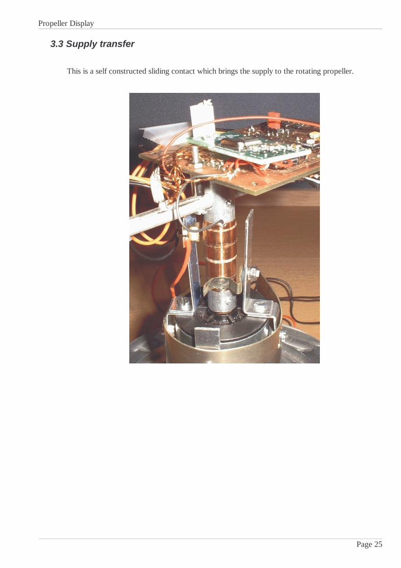
3.3 Supply transfer
This is a self constructed sliding contact which brings the supply to the rotating propeller.
Page 25

Propeller Display
3.4 LED DriverI realize a High-End variant with 16 pixel in the height. Every pixel can be red green or blue, so 16x3LED's are required.
3.4.1 Scheme
3.4.2 DescriptionA pixel can be switched completely on or off by a switch of the darlington driver. The color canbe selected when a single FET is switched on. It's possible to mix the colors when more than oneFET is switched on or when they're driven with PWM-Signals.
3.4.3 DimensioningKnown Values
FET RDS(on) = 0.8ΩULN2803 VCE(Sat) @ 20mA = ca. 0.6VLED Green VAK = 3.5VLED Blue VAK = 3.6VLED Red VAK = 1.75VAll LED's ILED(Max) = 20mA
Calculation of LED series resistor
RGre=V Supply−V AK−V CE Sat
I LED
−RDS on =5V −3.5V −0.6V
20mA−0.8= 44.2
RBlu =V Supply−V AK−V CE Sat
I LED
−RDS on =5V −3.6V −0.6V
20mA−0.8=39.2
RRd =V Supply−V AK−V CE Sat
I LED
−RDS on =5V −1.75V −0.6V
20mA−0.8=124
Page 26
Red Green Blue
5V
0 1 2 15
P-ChannelFET's
2 x ULN2803Darlington Driver

Propeller Display
3.4.4 Photo of the LED-PCB
3.4.5 Remarks
FET's
Normally the gate of a FET has a very high resistance to the other connections. But it has aparasitary capacitance (BSP315, CiSS_max = 400pF). When the gate is switched with a fast PWM
signal, very high currents may appear. Because the microcontroller can deliver only 2mA i protectit's output with a resistor.
RSeriesRestistance=UI= 5V
2mA=2.5k
Now even with a short circuit the current in or out to a port can't exceed 2mA.
Photo Interrupter
The photo interrupter is also located on the LED-PCB.
Page 27

Propeller Display
3.5 Terminal
3.5.1 ConstituentsThe terminal consists of the following parts:
Component Self made
Microcontroller PCB
LCD-Display
Radio PCB
Housing
Software
Expendable items (switches, battery, connectors, screws...)
3.5.2 Front
3.5.3 Connectors
Page 28
On/OFF Switch
CharacterSelector
Off On
Shift
Delete
Ext. PWR(External DC-Supply, >7V)
SCI2(Serial Interface)
Flash(Softwareupdate)
Normal Flash
GND +
Propeller Display
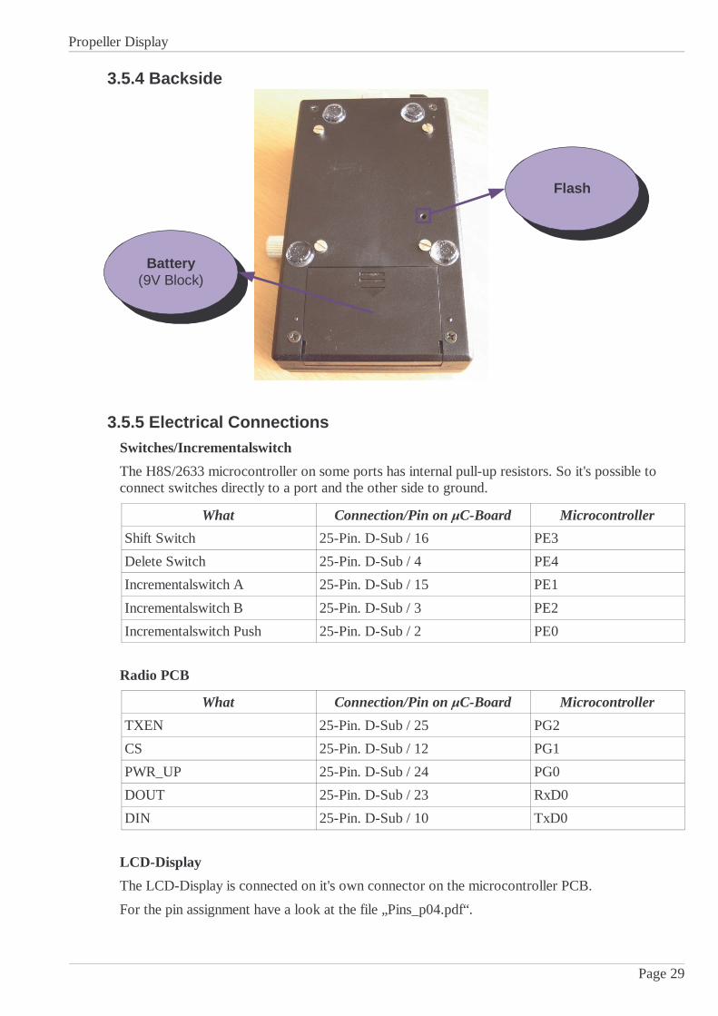
3.5.4 Backside
3.5.5 Electrical ConnectionsSwitches/Incrementalswitch
The H8S/2633 microcontroller on some ports has internal pull-up resistors. So it's possible toconnect switches directly to a port and the other side to ground.
What Connection/Pin on µC-Board Microcontroller
Shift Switch 25-Pin. D-Sub / 16 PE3
Delete Switch 25-Pin. D-Sub / 4 PE4
Incrementalswitch A 25-Pin. D-Sub / 15 PE1
Incrementalswitch B 25-Pin. D-Sub / 3 PE2
Incrementalswitch Push 25-Pin. D-Sub / 2 PE0
Radio PCB
What Connection/Pin on µC-Board Microcontroller
TXEN 25-Pin. D-Sub / 25 PG2
CS 25-Pin. D-Sub / 12 PG1
PWR_UP 25-Pin. D-Sub / 24 PG0
DOUT 25-Pin. D-Sub / 23 RxD0
DIN 25-Pin. D-Sub / 10 TxD0
LCD-Display
The LCD-Display is connected on it's own connector on the microcontroller PCB.
For the pin assignment have a look at the file „Pins_p04.pdf“.
Page 29
Flash
Battery(9V Block)

Propeller Display
3.6 Propeller
3.6.1 ConstituentsThe propeller consists of the following parts:
Component Self made
Microcontroller PCB
LED-PCB
Radio PCB
Motor
Supply transfer to the propeller
Mechanicals
Software
Expendable items (photo interrupter, connectors...)
3.6.2 Photo of the second prototype
3.6.3 ModificationThe photo interrupter on the LED-PCB didn't worked well, so i mountet it on the propeller arm.
For high speed's the LED-PCB was too flexible.
Page 30
LED-PCB
MicrocontrollerPCB
Photo Interrupter
Motor
Socket
Sliding Contact
Synchronization-Point
Radio PCB

Propeller Display
3.6.4 Electrical ConnectionsRadio PCB
What Connection/Pin on µC-Board Microcontroller
TXEN (Pin 1) 25-Pin. D-Sub / 25 PG2
CS (Pin 4) 25-Pin. D-Sub / 12 PG1
PWR_UP (Pin 2) 25-Pin. D-Sub / 24 PG0
DOUT (Pin 8) 25-Pin. D-Sub / 23 RxD0
DIN (Pin 6) 25-Pin. D-Sub / 10 TxD0
LED-PCB
What Connection/Pin on µC-Board Microcontroller
ROW1 (Pin 17) Blue JP4 / 3 PWM3
ROW2 (Pin 18) Green JP4 / 2 PWM2
ROW3 (Pin 19) Red JP4 / 1 PWM1
Photo interrupter (Pin 20) JP3 / 2 IRQ0
5V (Pin 25) 25-Pin. D-Sub / 14 -
GND (Pin 24) 25-Pin. D-Sub / 1 -
LED D1 (Pin 1) 25-Pin. D-Sub / 22 PD7
LED D2 (Pin 2) 25-Pin. D-Sub / 9 PD6
LED D3 (Pin 3) 25-Pin. D-Sub / 21 PD5
LED D4 (Pin 4) 25-Pin. D-Sub / 8 PD4
LED D5 (Pin 5) 25-Pin. D-Sub / 20 PD3
LED D6 (Pin 6) 25-Pin. D-Sub / 7 PD2
LED D7 (Pin 7) 25-Pin. D-Sub / 19 PD1
LED D8 (Pin 8) 25-Pin. D-Sub / 6 PD0
LED D9 (Pin 9) 25-Pin. D-Sub / 18 PE7
LED D10 (Pin 10) 25-Pin. D-Sub / 5 PE6
LED D11 (Pin 11) 25-Pin. D-Sub / 17 PE5
LED D12 (Pin 12) 25-Pin. D-Sub / 4 PE4
LED D13 (Pin 13) 25-Pin. D-Sub / 16 PE3
LED D14 (Pin 14) 25-Pin. D-Sub / 3 PE2
LED D15 (Pin 15) 25-Pin. D-Sub / 15 PE1
LED D16 (Pin 16) 25-Pin. D-Sub / 2 PE0
Page 31

Propeller Display
3.7 Software
3.7.1 Different Files
3.7.2 Build and flash the softwareAfter programming the software, the batchfile „compile.bat“ can be startet. This run's the GNU-Compiler which compiles the C-Files. After that the assembler assembles the assembler files.Compiler and assembler creates objectfiles which are compound to a single file by the linker. Withspecial commands the linker can create directly a flashable .mot file.
Page 32
makefile
Instructions to build thesoftware and create aflashable main.mot file.
ioh82633.h
Address and registerdefinitions of themicrocontroller.
startup.s
Startup code which initializesthe stack, variables etc. andstarts the main() function.
vectors.s
Vector table; defines whichfunction is associated withwhich interrupt.
isrhdl.s
IRQ-Handler; IRQ-Functionswhich are programmed inassembler.
main.c
File with the main software
LCD.c
Routines to drive a LCD-Display
LCD.h
This file is included when aLCD-Display is attached.
SCI.c
Routines for the serialinterface.
SCI.h
To use a serial interface, thisfile must be included.
main.mot
Flashable file for themicrocontroller.
linkcmd.x
Commands for the linker withaddress definitions (RAM,ROM, etc.).
LinkerCompiler
Assembler

Propeller Display
3.7.3 Rotation Switch
3.7.3.1 Introduction
This switch outputs three signals. One signal represents the push function. The other twosignals show the steps and direction of the rotation.
Following signals appear when the switch is rotated clockwise:
In resting state the signals A and B are both either low or high. Only if a step happens, firstsignal A changes it's state and after a short time also signal B.
Following signals appear when the switch is rotated counterclockwise:
Here firstly signal B changes on a step and then signal A.
Page 33
A
B
Clockwise
t
10 11 01 00 10 11 01 00 10Bit Pattern
Position 1 1 2 2 3 3 4 4 5
A
B
Counterclockwise
t
01 11 10 00 01 11 10 00 01Bit Pattern
Position -1 -1 -2 -2 -3 -3 -4 -4 -5
Propeller Display
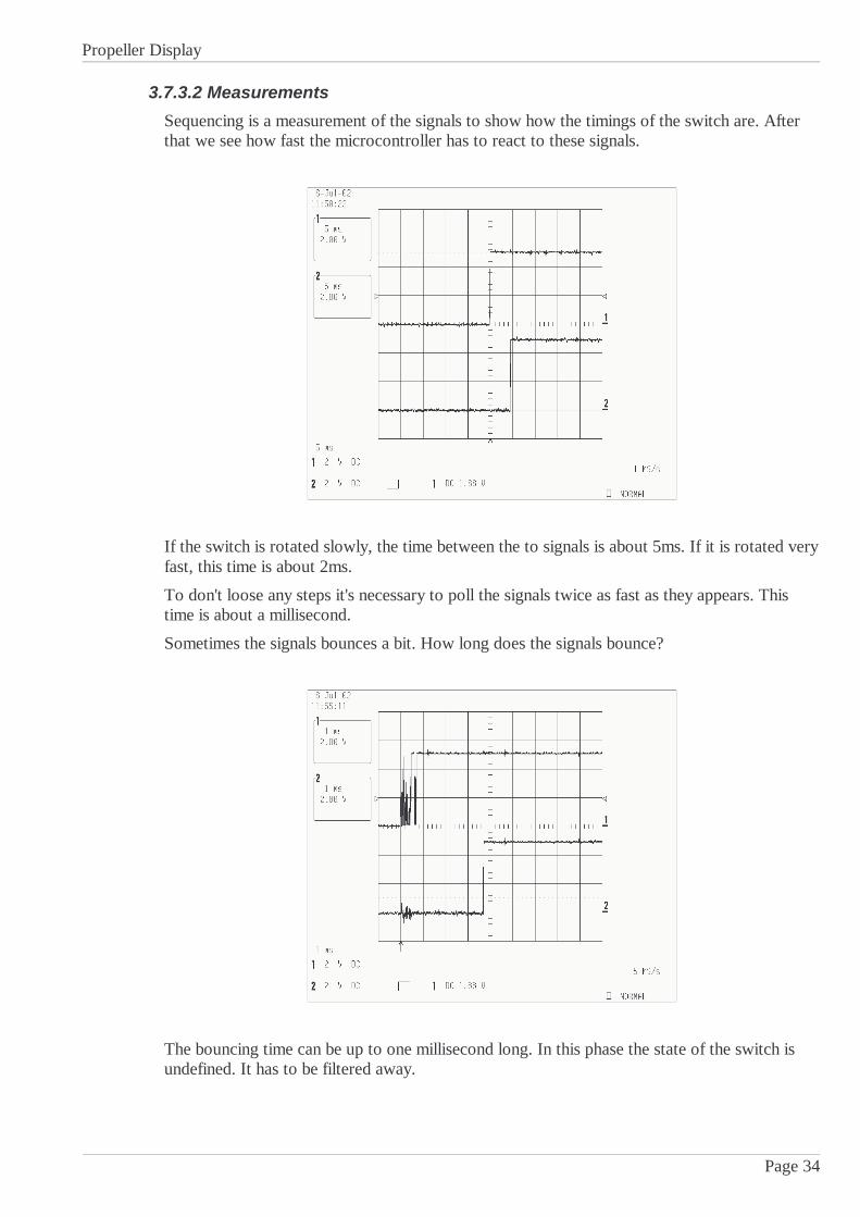
3.7.3.2 Measurements
Sequencing is a measurement of the signals to show how the timings of the switch are. Afterthat we see how fast the microcontroller has to react to these signals.
If the switch is rotated slowly, the time between the to signals is about 5ms. If it is rotated veryfast, this time is about 2ms.
To don't loose any steps it's necessary to poll the signals twice as fast as they appears. Thistime is about a millisecond.
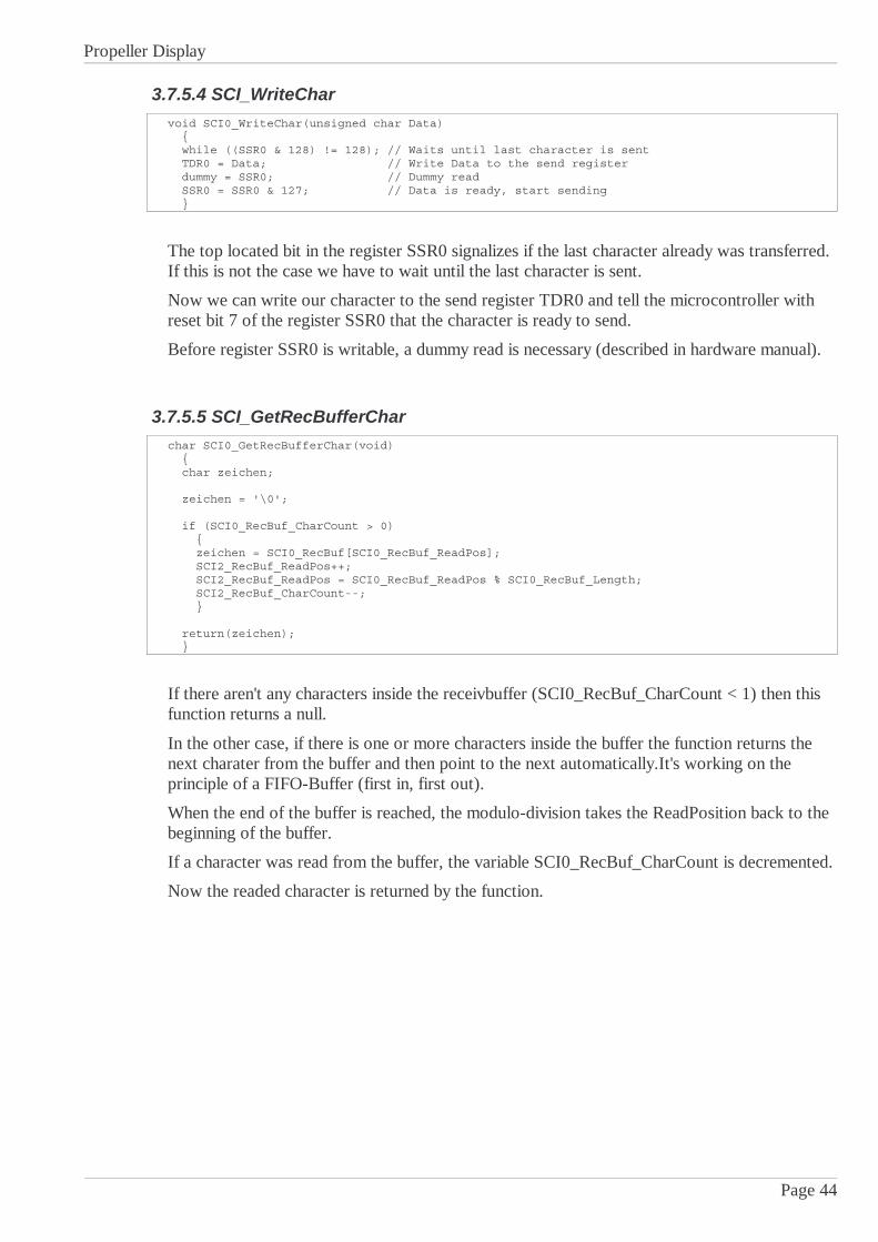
Sometimes the signals bounces a bit. How long does the signals bounce?
The bouncing time can be up to one millisecond long. In this phase the state of the switch isundefined. It has to be filtered away.
Page 34

Propeller Display
3.7.3.3 Solution with Interrupts
An elegantly way to react to the signals of the rotation switch is to fire an interrupt when astep appears. It's necessary to setup the IRQ's that these are reacting to the rising and fallingflanks of the signals.
If a step appears let's say interrupt A is fired firstly and when a step to the other side appears,interrupt B is fired firstly and after some time also the other interrupt.
Because of the bouncing of the signals when they change it's necessary to disable the interruptsin this time – about one millisecond.
I implemented this variant, but it has some problems:
Problem 1 (slow rotation)
If the rotation switch is rotated very slowly, the first interrupt appears and the software opinesthat one step has happened. After that (the interrupts are enabled after the bouncing time), theother interrupt appears and the software opines that a step on the other side appeared. But thisisn't true.
Problem 2 (fast rotation)
If the switch is rotated very fast it seems that the software is generating random numbers. Thisappears because after the bouncing time is over and the interrupts are enabled, it's not definedwhich interrupt is fired next time.
Conclusion
This solutions with the interrupts isn't a good solution. It works only if the user rotates theswitch with an average speed. Not too fast and not too slow.
3.7.3.4 Solution with a State Machine
My second solution is one with a state machine. The signals A and B of the rotation switch arepolled periodically and then given to a state machine.
Page 35
Pos+1Pos-1
= Resting State
A B A B
A B
A B A B
A B A B
A B
A B
A B

Propeller Display
This state machine was quite easy to implement:
void RotationSwitch_Read(void) unsigned char SwitchState; static unsigned int SwitchState_before = 0; SwitchState = PORTE & 6; // Take bits 1 and 2 from port E SwitchState = SwitchState >> 1; if (SwitchState != SwitchState_before) // If state changed switch (SwitchState) // On a step case 1: if (SwitchState_before == 3) // If switch was idle (11) RotationSwitch_counter++; // One step to the right UserInput = 1; // Signalisation for main-program else RotationSwitch_counter--; // One step to the left UserInput = 1; // Signalisation for main-program break; // On a step case 2: if (SwitchState_before == 0) // If switch was idle (00) RotationSwitch_counter++; // One step to the right UserInput = 1; // Signalisation for main-program else RotationSwitch_counter--; // One step to the left UserInput = 1; // Signalisation for main-program break; SwitchState_before = SwitchState;
Description of the code
The function „RotationSwitch_Read“ is called periodically by a timer interrupt everymillisecond.
In the variable „SwitchState“ is the current position of the switch. Only if something changedto the last poll, the next instructions are executed.
Only if the signals are different (case 1 or case 2) a step happend.
If the current SwitchState is 01 (dez 1) and before it was 11 (dez 3), then a step to the rightappeared.
If the current SwitchState is 01 (dez 1) and before it was 00 (dez 0), then a step to the leftappeared.
Test / Result
In contrast with the interrupt driven variant described before, this variant with the statemachine is working very well. Even if the switch is rotated very fast or very slow the resultsare great.
It is working best when the polling interval is about 2ms.
Page 36

Propeller Display
3.7.4 LCD Driver
3.7.4.1 Introduction
Standart character based LCD-Dispays use a HD44780 or compatible controller by Hitachi. Ithas a built in font and drives the LCD itself with the necessary voltages.
It's simple to use such a display; firstly it has to be initialized and after that the text can betransferred to the RAM of the display controller. The controller then shows this text on thelcd.
To save some pins on the microcontroller, i drive the display in the 4-Bit mode. Data istransferred in a high- and low-nibble.
All LCD related functions i put in a seperately C-File (lcd.c, lcd.h).
3.7.4.2 Function Overview
Name Description
LCD_Wait_Time The display controller is very slow, so this function waits untilthe display controller is ready for the next command.
LCD_Wait * Reads the busy-flag of the display controller and returns if thedisplay is ready for the next commands (only works afterinitialization of the display).
LCD_Init * Initializes the display.
Sets 4 or 8-Bit mode, cursor on/off, blinking of the cursor ect.
LCD_WriteInstr * Sends an instruction to the display
LCD_Clear Clears the display
LCD_Control Sets display avtive/passive, cursor on/off/blinking
LCD_SetCursor Puts the cursor to a specific line and character position
LCD_WriteChar * Puts a single character to the actual cursor position
LCD_WriteStr Writes a string (array of unsigned char) to the display until thezero character is reached (ASCII-Character 0).
LCD_WriteInt * Writes an integer value (signed 16-Bit) as text to the display.*These functions are explained below
Page 37

Propeller Display
3.7.4.3 LCD_Wait
void LCD_Wait(unsigned char Enable) unsigned char busy; PBDDR = 8 | 4 | 2 | 1; // Set all pins on port B as outputs, except D4 to D7 do PBDR = 4; // Read from Display PBDR = Enable | 4; // Read and Enable (High Nibble) busy = PORTB & 128; // Read Busy Flag PBDR = 4; // Enable low PBDR = Enable | 4; // Read and Enable (Low Nibble) PBDR = 4; // Enable low while (busy); // Repeat until Busy-Flag is reset PBDR = 0; // Disable / Write PBDDR = 255; // All pins as outputs
Firstly, all pins which are connected to the display except the data-bus (D4...D7) are defined asoutputs.
Then the signal R/W (Read/Write) is set to high, now we can read from the display.
If the enable signal is given to the display, it puts it's data on the bus and the microcontrollercan read it. First the high nibble of the data (upper 4 Bits) and on the next time the enablesignal is given, it outputs the low nibble (lower 4 Bits).
On large displays with 4 lines and 40 characters there are 2 controller chips. One is controllingthe upper 2 lines and the other the lower 2 lines. The controller is selected by give the right bitas parameter to the function.
Reading of the busy flag is repeated until it is reset and the display is ready to receive newcommand or data.
When the display is ready, all pins of port B are set to outputs.
Page 38

Propeller Display
3.7.4.4 LCD_Init
void LCD_Init(unsigned char DisplayType) unsigned char enable; enable = 9; // Init both display controllers (bit 0 and bit 3) PBDDR = 255; // Pord B as output LCD_Wait_Time(15); // Wait min. 15ms PBDR = enable; // Enable1, Enable2 PBDR = enable | 48; // Enable1, Enable2, Data (3), Init PBDR = 48; // Data (3) LCD_Wait_Time(5); // Wait min. 5ms PBDR = enable; // Enable1, Enable2 PBDR = enable | 48; // Enable1, Enable2, Data (3), Init PBDR = 48; // Data (3) LCD_Wait_Time(1); // Wait min. 160us PBDR = enable; // Enable1, Enable2 PBDR = enable | 48; // Enable1, Enable2, Data (3), Init PBDR = 48; // Data (3) LCD_Wait_Time(1); // Wait min. 160us PBDR = enable; // Enable1, Enable2 PBDR = enable | 32; // Enable1, Enable2, Data (2), 4-Bit Mode PBDR = 32; // Data (2) LCD_Wait_Time(1); // Wait min. 160us // From now, 2 Nibbles required LCD_WriteInstr(3, 40); // DataLength 4-Bit, 2 Lines, 5x8Dots Font LCD_Clear(); // Clear Display LCD_Control(3, 1, 0, 0); // Display On, Cursor Off, Blink Off LCD_WriteInstr(3, 128 | 0); // Set DDRAM Addr. 0
LCD_Wait_Time(1); // Wait // Set variables for different display types switch (DisplayType) // Display with 4 lines and 40 chracters case 0: DDRAM_Offset_Line_1 = 0; DDRAM_Offset_Line_2 = 64; DDRAM_Offset_Line_3 = 0; DDRAM_Offset_Line_4 = 64; ControllerCount = 2; break; // Display with 4 lines and 20 chracters case 1: DDRAM_Offset_Line_1 = 0; DDRAM_Offset_Line_2 = 64; DDRAM_Offset_Line_3 = 20; DDRAM_Offset_Line_4 = 84; ControllerCount = 1;
The initializing of the display is done according to the description in the datasheet of theHD44780 page 46.
After the initialization the DDRAM-Offset's are set equal to the display type which isconnected.
Possible values for the parameter DisplayType:
DisplayType Description
0 For display with 4 lines and 40 characters per line
1For display with 4 lines and 20 characters per line
For display with 2 lines and 20 characters per line
Page 39

Propeller Display
3.7.4.5 LCD_WriteInstr
void LCD_WriteInstr(unsigned char LCD_Controller, unsigned char Instr) unsigned char enable; switch (LCD_Controller) case 1: enable = 8; // Activates first LCD_Controller on the display break; case 2: enable = 1; // Activates second LCD_Controller on the display (on large displays) break; case 3: enable = 9; // Activates both LCD_Controller break; default: enable = 8; // Send High Nibble PBDR = enable; // Enable1, Enable2 PBDR = enable | (240 & Instr); // Enable and HighNibble from Instr PBDR = 240 & Instr; // HighNibble from Instr LCD_Wait(enable); // wait 37us (?) // Send Low Nibble Instr = Instr << 4; PBDR = enable; // Enable1, Enable2 PBDR = enable | Instr; // Enable and LowNibble from Instr PBDR = Instr; // LowNibble from Instr LCD_Wait(enable); // wait 37us (?)
Possible values for the parameter LCD_Controller:
LCD_Controller Description
1 Selects first controller
2 Selects second controller
3 Sends the command to both controllers simultaneous
Firstly the HighNibble of the instruction is sent to the display; The enable signal is going tohigh, after that additionally the upper 4 bits of the instructions are put on the bus. When theenable is going to low and the data is still on the bus, the displays inputs this data.
Now the busy flag is read and when the display is ready, the same happens to the lower 4 bitsof the instruction.
When the busy flag is low, the instruction has been executed by the display and it is ready forthe next instruction.
Page 40

Propeller Display
3.7.4.6 LCD_WriteChar
Example
LCD_WriteChar(8, ' C');
Enables display controller 1 and writes a C to the current cursor position.
3.7.4.7 LCD_WriteInt
Example
LCD_WriteInt(1, 5, -232);
Writes -232 on line 1 of the display on cursor position 5.
Page 41

Propeller Display
3.7.5 Serial Interface
3.7.5.1 Introduction
The H8S/2633 microcontroller has 5 serial interfaces built in. Other microcontrollers can beconnected to it, a PC or other peripherals.
Every serial interface (SCI) can be synchronous, asynchronous, has it's own baudrate and dataformat ( or 8 databits, parity, number of stoppbits).
One SCI has the possibility to drive an IrDA transceiver chip directly.
All SCI based functions are collected together in the files sci.c and sci.h. In a project simply thesci.h can be included and then a serial interface can be used.
3.7.5.2 Function Overview
Name Function
SCI_Init * Initializes the serial interface. Sets the baudrate, activates theinterface, enables the required interrupts etc.
SCI_WriteChar * Writes a character to the send-buffer. If the interface is ready, itsends out this character and deletes it from the buffer.
SCI_WriteStr Sends a whole string to the serial interface until the zero-character is reached. (Uses SCI_WriteChar)
SCI_WriteLn Same as SCI_WriteStr, but adds a CR (Carriage Return) and LF(Line Feed) to the string.
SCI_WriteCRLF Sends a Carriage Return and Line Feed
SCI_WriteInt Converts a 16-bit integer value to a string and sends it to theserial interface.
SCI_GetRecBufferCount Returns the number of characters in the receivebuffer.
SCI_GetSenBufferCount Returns the number of characters in the sendbuffer.
SCI_GetRecBufferChar * Gets a character from the receivebuffer and deletes it from thebuffer.
SCI_IRQRecChar * Interrupt funktion which receives a character and puts it on thereceivebuffer.
*These functions are explained below
Page 42

Propeller Display
3.7.5.3 SCI_Init
void SCI0_Init(void) // Like example in hardware manual page 621 unsigned int index; unsigned int wait; unsigned char Clock; SCI0_RecBuf_CharCount = 0; SCI0_SenBuf_CharCount = 0; // Initialize receivebuffer for (index=0; index<SCI0_RecBuf_Length; index++) SCI0_RecBuf[index] = '\0'; // Initialize sendbuffer for (index=0; index<SCI0_SenBuf_Length; index++) SCI0_SenBuf[index] = '\0'; Clock = 0; // SCI Clock = Internal (Asynchronous Mode) MSTPCRB = MSTPCRB & 127; // SCI0 Start (Bit 7 => 0) SCR0 = SCR0 & 207; // Reset TE- and RE-Bits SCR0 = (SCR0 & 207) | Clock; // Set Clock SMR0 = 0; // Asynch, 8-Bit, No Parity, Even Parity, 1 Stop Bit, NoMultiproc., Clock = Phi SCMR0 = 0; // Normal SCI Operation (No Smart Card) BRR0 = 29; // 19200 Baud => n = 0, N = 29 for (wait=0; wait<2000; wait++); // Wait min. a 1-Bit-Interval SCR0 = 64 | 32 | 16; // Receive IRQ, Rx/Tx Enabled, Asynch. Clock
We take a look at the initializing of SCI0, the first serial interface of the H8S/2633microcontroller.
Firstly the variables SCI_RecBuf_CharCount and SCI_SenBuf_CharCount are set to 0. In thisvariables is stored, how many characters are in the buffers. These buffers are realized insoftware.
Now both buffers are initialized, therefore they are filled with null characters in a for-loop.
The Variable Clock defines if the clock for the serial interface is generated internally or isconnected externally. In synchronous mode, the clock is coming from outside when data isreceived.
In the „Module Stop Control Register B“ the serial interface can be started.
Now the parameters for the dataformat can be set. I take a european quasi standart; 8-Bit data,no parity, one stoppbit and a baudrate of 19200.
The value for the baudrateregister „BRR2“ has to be calculated.
NBRR2
=
64⋅22n −1⋅B⋅106−1= 18.432
64⋅22⋅ 0− 1⋅19200106−1=29
Φ = Main-Clock in MHz, n = Baudratengenerator Clock, B = Baudrate
After waiting a bit and setting SCR0 again, the interface is ready to communicate.
Page 43
Propeller Display
3.7.5.4 SCI_WriteChar
void SCI0_WriteChar(unsigned char Data) while ((SSR0 & 128) != 128); // Waits until last character is sent TDR0 = Data; // Write Data to the send register dummy = SSR0; // Dummy read SSR0 = SSR0 & 127; // Data is ready, start sending
The top located bit in the register SSR0 signalizes if the last character already was transferred.If this is not the case we have to wait until the last character is sent.
Now we can write our character to the send register TDR0 and tell the microcontroller withreset bit 7 of the register SSR0 that the character is ready to send.
Before register SSR0 is writable, a dummy read is necessary (described in hardware manual).
3.7.5.5 SCI_GetRecBufferCharchar SCI0_GetRecBufferChar(void) char zeichen; zeichen = '\0'; if (SCI0_RecBuf_CharCount > 0) zeichen = SCI0_RecBuf[SCI0_RecBuf_ReadPos]; SCI2_RecBuf_ReadPos++; SCI2_RecBuf_ReadPos = SCI0_RecBuf_ReadPos % SCI0_RecBuf_Length; SCI2_RecBuf_CharCount--; return(zeichen);
If there aren't any characters inside the receivbuffer (SCI0_RecBuf_CharCount < 1) then thisfunction returns a null.
In the other case, if there is one or more characters inside the buffer the function returns thenext charater from the buffer and then point to the next automatically.It's working on theprinciple of a FIFO-Buffer (first in, first out).
When the end of the buffer is reached, the modulo-division takes the ReadPosition back to thebeginning of the buffer.
If a character was read from the buffer, the variable SCI0_RecBuf_CharCount is decremented.
Now the readed character is returned by the function.
Page 44

Propeller Display
3.7.5.6 SCI_IRQRecChar
#pragma interruptvoid SCI0_IRQRecChar(void) // Write a character to the buffy when it isn't full if (SCI0_RecBuf_CharCount < SCI0_RecBuf_Length) SCI0_RecBuf[SCI0_RecBuf_WritePos] = RDR0; SCI0_RecBuf_WritePos++; SCI0_RecBuf_WritePos = SCI0_RecBuf_WritePos % SCI0_RecBuf_Length; // Go back to thebeginning of the buffer SCI0_RecBuf_CharCount++; dummy = SSR0; SSR0 = SSR0 & 191; // RDRF (Receive Data Register Full) reset flag
This function cannot be used directly.
If the microcontroller received a character, it fires an interrupt and then this function is called.
It stores the received character in the receive buffer and increments the variableSCI0_RecBuf_CharCount which shows the main program how many characters are currentlyin the buffer.
When the end of the buffer is reached and it isn't full, the modulo division takes theSCI0_RecBuf_WritePos variable to the beginning of the buffer.
If the buffer is full and no more characters can be received because the main program doesn'tempties the buffer, the received characters are deleted.
Last but not least the interrupt flag has to be reset. If not, the interrupt is fired again but nonew character was received and we get an endless loop.
Page 45

Propeller Display
3.7.6 Wireless data transfer
3.7.6.1 Introduction
For the wireless data transfer between terminal and propeller display i take a „ nRF401 LoopModule“ from Nordic. It can be connected to a serial interface of the microcontroller.
Beside the serial interface, three signals which controls the radio module has to be connected:
Signal Description
TXEN Transmit enable (0 = Receive, 1 = Send)
PWR_UP Power On/Off (0 = Standby, 1 = On)
CS Channel Selection (0 = CH1 433.92MHz, 1 = CH2 434.33MHz)
These signals are connected to port G of the microcontroller and can be controlled bysoftware.
For the data transfer between the radio module and the microcontroller i take SCI0. Both serialinterfaces are working with 5V, so they can be connected directly together. The receive andtransmit signals has to be crossed out between these two devices.
The receiver on the radio module has a built in PLL which synchronizes the clock with theclock of the sender. To give the receiver a chance to do this synchronization it's necessary tosend this bitpattern some times: „10101010“. This correspondents to the decimal value 170.
After this, to synchronize der UART's it's recommended to send this bitpattern: „11111111“.
Now the UART of the receiver can receive the startbit of the following byte correctly.
When there is no sender near the receiver, the receiver is receiving only noise. So themicrocontroller has to filter out the data of the noise. For this a simple protocoll is introduced.The microcontroller scans the data stream and looks for a predefined start-sequency. After thisit receives all characters until the final-sequency appears.
Page 46
Propeller Display
3.7.6.2 Protocol
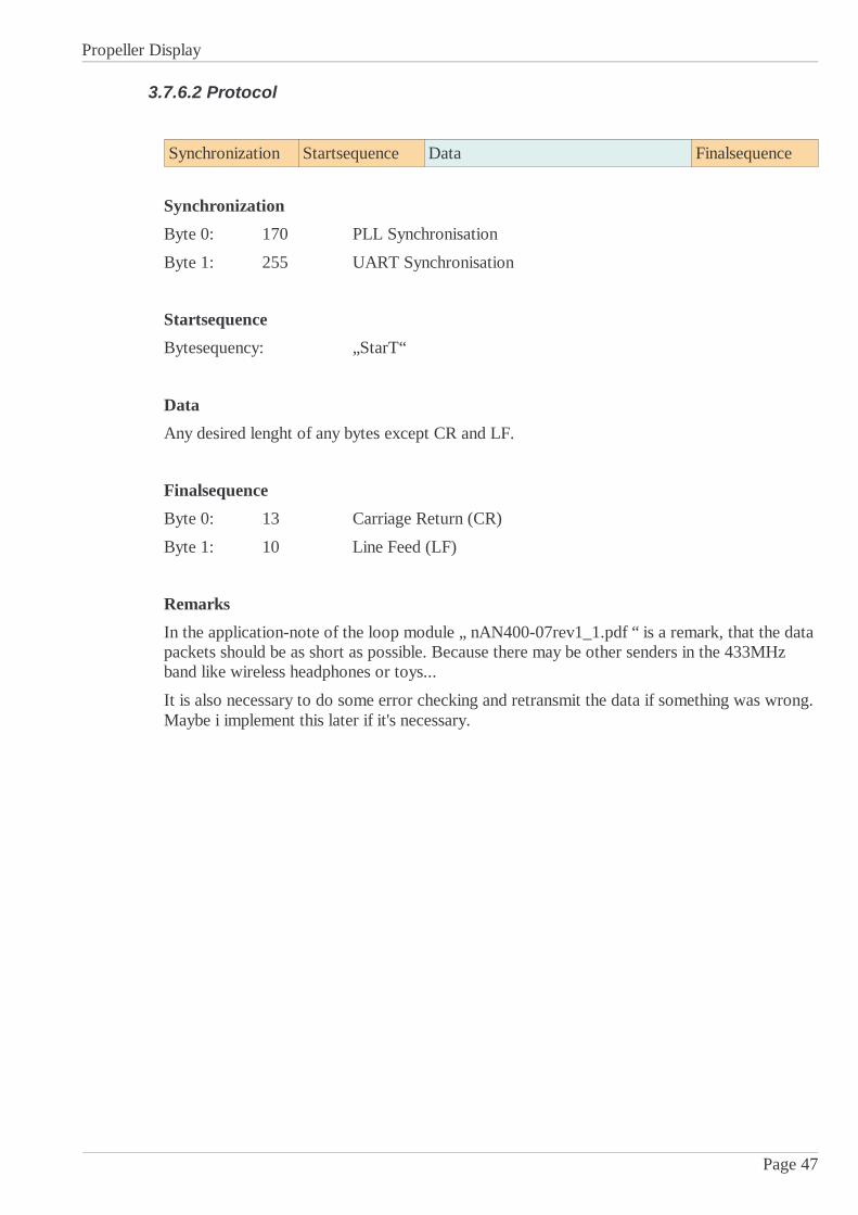
Synchronization Startsequence Data Finalsequence
Synchronization
Byte 0: 170 PLL Synchronisation
Byte 1: 255 UART Synchronisation
Startsequence
Bytesequency: „StarT“
Data
Any desired lenght of any bytes except CR and LF.
Finalsequence
Byte 0: 13 Carriage Return (CR)
Byte 1: 10 Line Feed (LF)
Remarks
In the application-note of the loop module „ nAN400-07rev1_1.pdf “ is a remark, that the datapackets should be as short as possible. Because there may be other senders in the 433MHzband like wireless headphones or toys...
It is also necessary to do some error checking and retransmit the data if something was wrong.Maybe i implement this later if it's necessary.
Page 47
Propeller Display
3.7.6.3 RF_SendStr
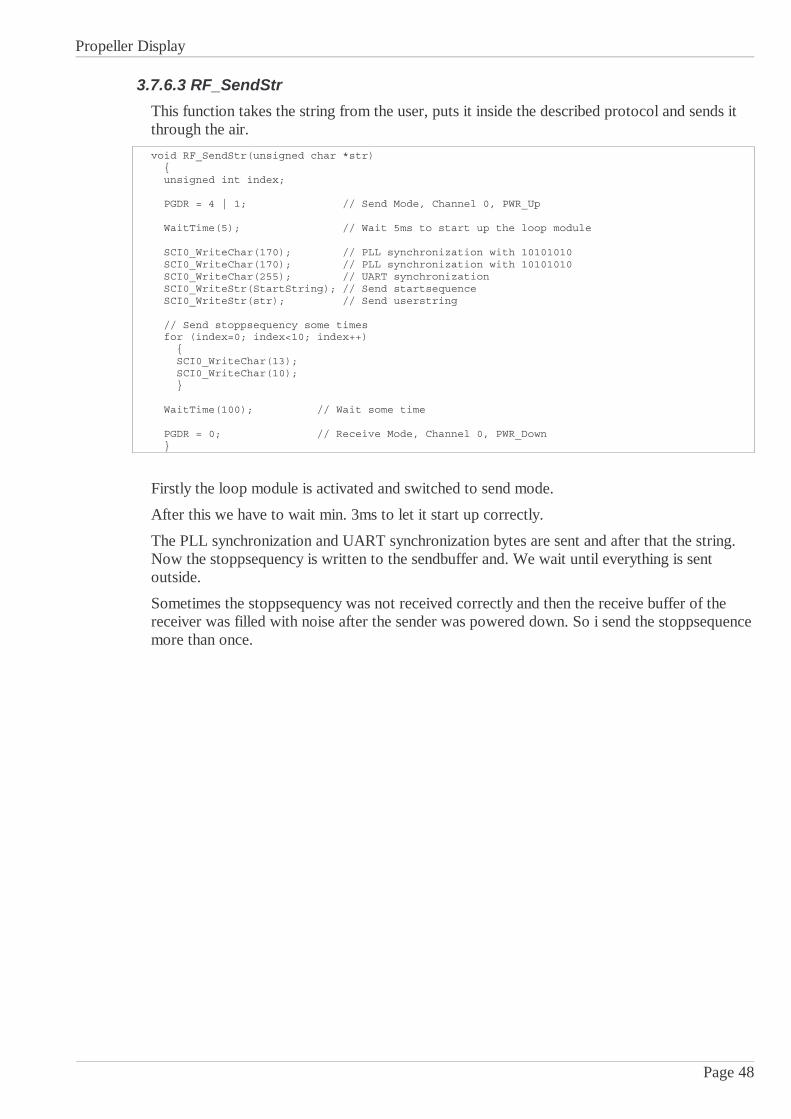
This function takes the string from the user, puts it inside the described protocol and sends itthrough the air.
void RF_SendStr(unsigned char *str) unsigned int index; PGDR = 4 | 1; // Send Mode, Channel 0, PWR_Up
WaitTime(5); // Wait 5ms to start up the loop module SCI0_WriteChar(170); // PLL synchronization with 10101010 SCI0_WriteChar(170); // PLL synchronization with 10101010 SCI0_WriteChar(255); // UART synchronization SCI0_WriteStr(StartString); // Send startsequence SCI0_WriteStr(str); // Send userstring // Send stoppsequency some times for (index=0; index<10; index++) SCI0_WriteChar(13); SCI0_WriteChar(10); WaitTime(100); // Wait some time PGDR = 0; // Receive Mode, Channel 0, PWR_Down
Firstly the loop module is activated and switched to send mode.
After this we have to wait min. 3ms to let it start up correctly.
The PLL synchronization and UART synchronization bytes are sent and after that the string.Now the stoppsequency is written to the sendbuffer and. We wait until everything is sentoutside.
Sometimes the stoppsequency was not received correctly and then the receive buffer of thereceiver was filled with noise after the sender was powered down. So i send the stoppsequencemore than once.
Page 48

Propeller Display
3.7.7 Moving Message Display
3.7.7.1 Introduction & Principle
Before the text can be displayed, it has to be converted to a bitmap and stored in an array.Because the H8S/2633 has a lot of RAM, i store the whole text as a bitmap in it.
After the conversion, the bitmap can simply transferred periodically to the LED's whichdisplays the picture column by column.
The eye of the visitor puts these colums together to the complete picture.
To convert a string to a bitmap it's necessary to have a font. Every possible character is storedin the flash. A little routine copies the single characters together to obtain a whole string.
Have a look to this principle:
Because the motor of the propeller turns clockwise, the microcontroller has to output thepicture from the right side to the left. If the direction would be wrong, the text appearsmirrored.
3.7.7.2 Scrolling
Scrolling is relatively easy to implement too. A window which complies to the pixelcount ofone round of the propeller is moved over the picture.
Only the pixels in this window are putted out bye the LED's.
When this window moves, also the displayed text moves and it looks like scrolling.
Page 49
Font
Picture
...whole alphabet
LED's
Bytewise scanning of the picture
Display-Window
Window is moving across the whole picture
Picture (array)
Bytewise scanning of the picturefrom the display-window

Propeller Display
3.7.7.3 Creating the bitmap (function: InsertText)
This sequence copies the characters of the font to the bitmap (picture) until the end of thestring is reached.
Start
Copy column (index) fromcharacter to the picture
(PixelX)
End of string?
PixelX++Picturelength++
index++
No
YesEnd
Picturelength = 0PixelX = 0
String* = 0 (Pointer to String)
index > 4
No
index = 0
Copy a 0 to the picture toobtain a little space of one
pixel.PixelX++
Picturelength++String*++
Yes
Afte the process of create the bitmap in the variable „PictureLength“ the horizontal pixelcountis available. The function to scroll the picture needs this information.
Page 50

Propeller Display
Here is the implementation of the picture creation:
void InsertText(unsigned char *str) char NoPicture; int index; int color; while (*str != '\0') // If it is a picture and not a character insert it NoPicture = 1; switch (*str) case 177: InsertPicture(0); // TSU-Logo NoPicture = 0; break; case 178: InsertPicture(1); // Colortest NoPicture = 0; break; case 179: InsertPicture(2); // Smiley NoPicture = 0; break;...<snip> case 186: for (index=0; index<32; index++) InsertPicture(9); // Animation: Running man ScrollSteps = 16; NoPicture = 0; break; case 187: for (index=0; index<9; index++) InsertPicture(10); // Animation: Coin ScrollSteps = 16; NoPicture = 0; break; // If it isn't a picture, it's a character if (NoPicture) for (index=0; index<5; index++) for (color=0; color<3; color++) Picture[PictureLength][color] = font[*str][index]; // Update Picture-Length if (PictureLength < PictureLengthMax) PictureLength++; for (color=0; color<3; color++) Picture[PictureLength][color] = 0; // Space between the characters // Update Picture-Length if (PictureLength < PictureLengthMax) PictureLength++; str++; // Next character DisplayPosition = 0 - DisplayLength;
Page 51

Propeller Display
When this function is called and given a pointer to it which points to a string (character array),it converts the string into a bitmap.
It copies all characters to the bitmap until the end of the string (zero) is reached.
At the end the variable „PictureLength“ shows the length of the created picture.
I used some unused characters as placeholders for pictures. The pictures are also stored in theflash and simply copied to the displayed bitmap.
Remarks
Because the color cannot been chosen the font is copied to the red, blue and green picturearray. So the text appears as white.
Page 52
Propeller Display
3.7.7.4 Implementation of the scrolling
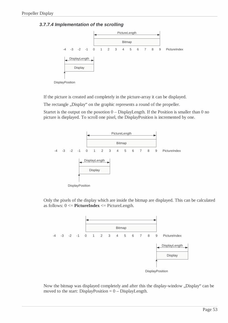
If the picture is created and completely in the picture-array it can be displayed.
The rectangle „Display“ on the graphic represents a round of the propeller.
Startet is the output on the posotion 0 – DisplayLength. If the Position is smaller than 0 nopicture is dieplayed. To scroll one pixel, the DisplayPosition is incremented by one.
Only the pixels of the display which are inside the bitmap are displayed. This can be calculatedas follows: 0 <= PictureIndex <= PictureLength.
Now the bitmap was displayed completely and after this the display-window „Display“ can bemoved to the start: DisplayPosition = 0 – DisplayLength.
Page 53
Bitmap
PictureLength
Display
DisplayLength
PictureIndex
DisplayPosition
0 1 2 3 4 5 6 7 8 9-4 -3 -2 -1
Bitmap
PictureLength
Display
DisplayLength
PictureIndex
DisplayPosition
0 1 2 3 4 5 6 7 8 9-4 -3 -2 -1
Bitmap
Display
DisplayLength
PictureIndex
DisplayPosition
0 1 2 3 4 5 6 7 8 9-4 -3 -2 -1

Propeller Display
3.7.7.5 Picture synchronization (IRQ0)
Every time the light beam of the photo interrupter is interrupted, IRQ0 is fired.
The function synchronizes the timer which drives the LED's by resetting it to 0. Also thescrolling is issued in this moment.
Code for IRQ0 (called by the photo interrupter)
void IRQ0(void) TCNT0 = 0; // Reset Timer
PictureIndex = DisplayPosition + DisplayLength; // Scroll DisplayPosition = DisplayPosition + ScrollSteps; if (DisplayPosition > PictureLength) DisplayPosition = 0 - DisplayLength; dummy = ISR; ISR = ISR & 254; // Interrupt 0 rücksetzen
After every time a round from the propeller is complete, the photo interrupter creates thisinterrupt and calls the IRQ-Function IRQ0.
To synchronize the timer with the propeller, the timer value is set to 0. Now the scrollingappears with actualize the variable „DisplayPosition“. If the scrolling has to be pixelwise, 1 isadded to „DisplayPosition“.
When a higher value than 1 is added after a round, the text scrolls faster.
Page 54
Start(IRQ0 from photo
interrupter)
No
YesSet DisplayPosition) to the
beginning
Reset timer(TCNT0 = 0),
Scroll (calculate newPictureIndex
End
Showed whole picture?
Propeller Display
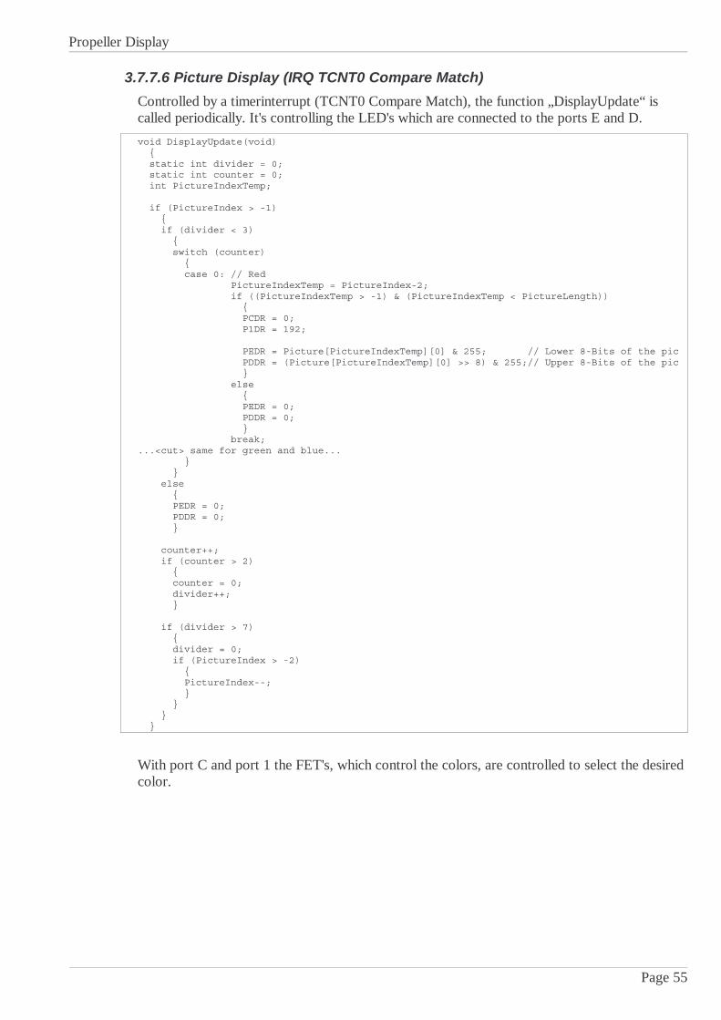
3.7.7.6 Picture Display (IRQ TCNT0 Compare Match)
Controlled by a timerinterrupt (TCNT0 Compare Match), the function „DisplayUpdate“ iscalled periodically. It's controlling the LED's which are connected to the ports E and D.
void DisplayUpdate(void) static int divider = 0; static int counter = 0; int PictureIndexTemp; if (PictureIndex > -1) if (divider < 3) switch (counter) case 0: // Red PictureIndexTemp = PictureIndex-2; if ((PictureIndexTemp > -1) & (PictureIndexTemp < PictureLength)) PCDR = 0; P1DR = 192; PEDR = Picture[PictureIndexTemp][0] & 255; // Lower 8-Bits of the pic PDDR = (Picture[PictureIndexTemp][0] >> 8) & 255;// Upper 8-Bits of the pic else PEDR = 0; PDDR = 0; break;...<cut> same for green and blue... else PEDR = 0; PDDR = 0; counter++; if (counter > 2) counter = 0; divider++; if (divider > 7) divider = 0; if (PictureIndex > -2) PictureIndex--;
With port C and port 1 the FET's, which control the colors, are controlled to select the desiredcolor.
Page 55

Propeller Display
Remarks
For a nicer picture the LED's only flashes a short time when the propeller is on a position.Then they are darkly while the propeller move the LED's to the next pixel position and theyflash again. This is done with the divider.
Page 56
Improved Display
Normal Display

Propeller Display
3.7.8 Software for the Terminal
3.7.8.1 Sequency
Page 57
Power Up
Character entered?No
Yes
Wait 2 seconds
Welcome screen
Send string wireless to thePropeller Display
Final character?
Show "sending succesful"message
Yes
No
Add character to the string
Display actual string on theLCD-Display
Wait 2 seconds
Propeller Display
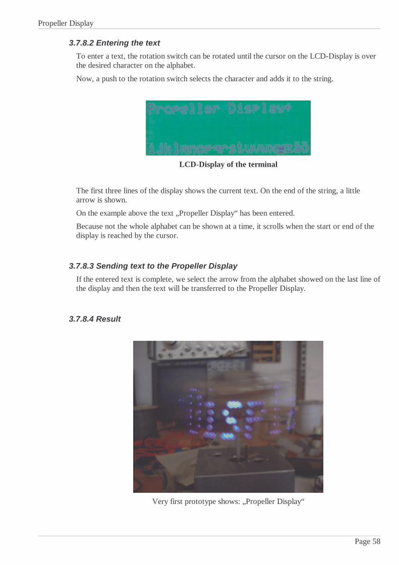
3.7.8.2 Entering the text
To enter a text, the rotation switch can be rotated until the cursor on the LCD-Display is overthe desired character on the alphabet.
Now, a push to the rotation switch selects the character and adds it to the string.
LCD-Display of the terminal
The first three lines of the display shows the current text. On the end of the string, a littlearrow is shown.
On the example above the text „Propeller Display“ has been entered.
Because not the whole alphabet can be shown at a time, it scrolls when the start or end of thedisplay is reached by the cursor.
3.7.8.3 Sending text to the Propeller Display
If the entered text is complete, we select the arrow from the alphabet showed on the last line ofthe display and then the text will be transferred to the Propeller Display.
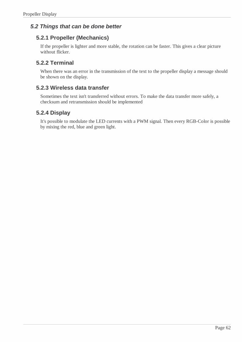
3.7.8.4 Result
Very first prototype shows: „Propeller Display“
Page 58

Propeller Display
3.7.9 Font EditorIn Delphi i programmed a little font editor.
On top of the program a ASCII code can be selected.
After that, by clicking on the virtually LED's the character can be designed.
When the program will be closed, it generates a C-File with an array with the bitmappedcharacters in it. The organization is as follows: font[ASCII-Code][index]. Each bit represents apixel.
This generated C-File can be included in the project.
Automatically generated code with the font
const unsigned char font[256][5] = 218,140,220,148,218, 228,138,68,42,196, 236,130,78,42,204, 196,42,202,42,196, 194,34,194,38,194, 0,0,0,0,0, 0,0,242,0,0, 0,224,0,224,0, 40,254,40,254,40, 36,84,254,84,72, 196,200,16,38,70,... 48,138,10,138,60;
Page 59
Show/Editcharacter
Select ASCII-Code
Close Program
Propeller Display
4 Tests
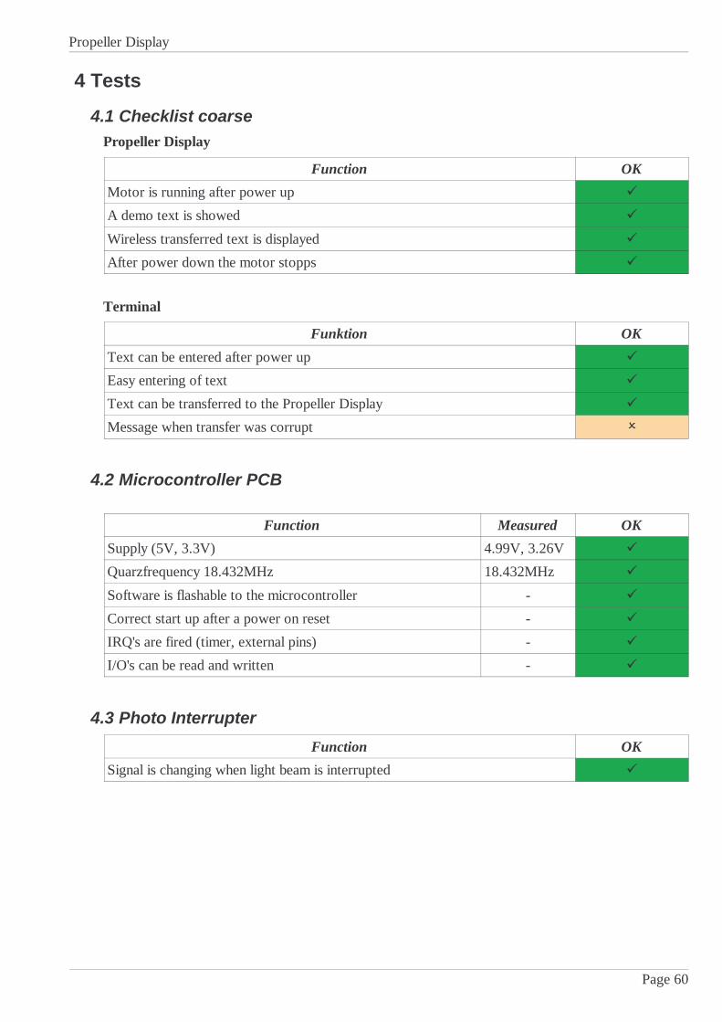
4.1 Checklist coarsePropeller Display
Function OK
Motor is running after power up
A demo text is showed
Wireless transferred text is displayed
After power down the motor stopps
Terminal
Funktion OK
Text can be entered after power up
Easy entering of text
Text can be transferred to the Propeller Display
Message when transfer was corrupt
4.2 Microcontroller PCB
Function Measured OK
Supply (5V, 3.3V) 4.99V, 3.26V
Quarzfrequency 18.432MHz 18.432MHz
Software is flashable to the microcontroller -
Correct start up after a power on reset -
IRQ's are fired (timer, external pins) -
I/O's can be read and written -
4.3 Photo Interrupter
Function OK
Signal is changing when light beam is interrupted
Page 60

Propeller Display
5 Finish
5.1 ChecklistAre the postulated parts of the project ok?
Project part OK
Basics elaborated
Priorities elaborated
Realizing of the mechanics
Bring power to the propeller (without battery)
Wireless data transfer to the propeller
Drive the LED's correctly
Tests
Optional: Receive a SMS from a handy and show the text
Photo of the second prototype
Page 61
Propeller Display
5.2 Things that can be done better
5.2.1 Propeller (Mechanics)If the propeller is lighter and more stable, the rotation can be faster. This gives a clear picturewithout flicker.
5.2.2 TerminalWhen there was an error in the transmission of the text to the propeller display a message shouldbe shown on the display.
5.2.3 Wireless data transferSometimes the text isn't transferred without errors. To make the data transfer more safely, achecksum and retransmission should be implemented
5.2.4 DisplayIt's possible to modulate the LED currents with a PWM signal. Then every RGB-Color is possibleby mixing the red, blue and green light.
Page 62