ProLINE-RoadRunner XLF Service...
85
ProLINE-RoadRunner™ XLF Service Manual for Siemens 80F4; 80F5, F, S, HF, and (limited) HS Series, D Series, X3 PN 096-0261-001 Service For installation, operation, maintenance, and troubleshooting, see the ProLINE- RoadRunner Owner’s Manual
Transcript of ProLINE-RoadRunner XLF Service...

ProLINE-RoadRunner™ XLF Service Manual for Siemens 80F4; 80F5, F, S, HF, and (limited) HS Series, D Series, X3
PN 096-0261-001
Service
For
installation,
operation,
maintenance,
and
troubleshooting,
see the ProLINE-RoadRunner Owner’s Manual

Data I/O has made a conscientious effort to ensure that the information in this document is accurate and complete. Data I/O assumes no liability for errors, or for any incidental, consequential, indirect, or special damages, including, without limitation, loss of use, loss or alteration of data, delays, or lost profits or savings, arising from the use of this document or the product which it accompanies.
No part of this document may be reproduced or transmitted in any form or by any means, electronic or mechanical, for any purpose, without written permission from Data I/O Corporation. Data I/O order forms may be reproduced for internal use only.
Data I/O is a registered trademark of Data I/O Corporation. TaskLink and ProLINE-RoadRunner are trademarks of Data I/O Corporation.
Data I/O Corporation acknowledges the trademarks of other organizations for their respective products or services mentioned in this document.
Technical Documentation Dept. also acknowledges the RoadRunner team members for supporting the flow of information into this manual.
We are interested in your comments— e-mail: [email protected]
© 2004–2008 Data I/O CorporationAll rights reserved

Data I/O • ProLINE-RoadRunner Service Manual • 096-0261 i
Contents096-0261-001
For non-service information see the Owner’s Manual, 096-0240.
Precautions for Safe Operation iii
RoadRunner Models Covered in this Manual SX–1
Replaceable Modules SX–2Tools Required SX–2
Components Overview SX–4Component List SX–5
Covers SX–6Removing the Robotics Cover SX–7Removing the Electronic Covers SX–7Removing the Conveyor Module Cover SX–8Removing the Control Panel Cover SX–8
Tape-In Module SX–10Removing the 32/44 mm Tape-In Module SX–11
Pneumatic Module SX–14Replacing the Vacuum Filters SX–15Removing the Pneumatic Module SX–16Reinstalling the Pneumatic Module SX–19Adjusting the Low Air Pressure Sensor SX–19
Cover Tape Module and Tensioner SX–22Removing the Cover Tape Module SX–23Removing the Tape Tension Sensor SX–23Removing the Tape Tension Assembly SX–24
Conveyor Module SX–26Removing the Conveyor Module SX–27Adjusting the End-of-Belt Sensor SX–28
Reject Bin SX–32Removing the Reject Bin Sensors SX–33

ii Data I/O • ProLINE-RoadRunner Service Manual • 096-0261
Control Panel Module SX–36Removing the Control Panel Module SX–37
PC Card Drive SX–40Removing the PC Card Drive SX–41
Pick and Place Head SX–42Aligning Pick and Place Points SX–42Adjusting and Balancing Probe Speed SX–42Adjusting Probe-Raising Speed SX–44Resetting the Pick Delay and Travel Delay Times SX–46Adjusting Probe Vacuum Sensors SX–47Removing the PNP Head SX–50
Programmer Module SX–52Removing the Programmer Module SX–53
NVRAM Battery SX–58Removing the NVRAM Battery SX–59Installing a new NVRAM Battery SX–61Reinstalling Components SX–61Reteaching the NVRAM SX–61
Linear Stage Module SX–64Removing the Linear Stage Module SX–65
Spare Parts Kits SX–68
Basic Spares Kit, RoadRunner XLF SX–70Replacing the Probe Tips SX–71Replacing the Air Inlet Tube Assembly SX–71
Self-Service Spares Kit, RoadRunner XLF SX–72
Socket Adapter and Actuator SX–74
Alphabetical Index Index–1

Data I/O • ProLINE-RoadRunner Service Manual • 096-0261 iii
Precautions for Safe OperationThe RoadRunner System has been designed for safe and efficient operation. The system can be dangerous if the RoadRunner safety features and precautions in this manual are ignored.
To avoid possible personal injury or damage to the equipment, please observe the following practices:
• Only trained personnel should install, maintain, repair, or troubleshoot this system.
• Do not operate the ProLINE-RoadRunner unless you have been thor-oughly trained, and have read and understand the instructions in this manual, particularly those that describe the system’s safety features.
• Do not use ProLINE-RoadRunner for any application other than its intended use.
• Do not operate the system if the guards or safety devices are not in their normal operating positions.
• Do not operate RoadRunner with any of the outer sheet metal panels removed.
• Do not operate RoadRunner while servicing, replacing, or adjusting any component unless directed to do so in this manual. Make sure that the RoadRunner is properly shut down before performing any of these operations.
• Do not place any part of your body near or in the direct path of moving parts.
• Do not disable or attempt to defeat any of the protective safety features of this system. Personal injury or equipment damage can occur if any safety systems on RoadRunner are disabled. If you suspect that a safety feature of the RoadRunner is damaged or malfunctioning, stop using the RoadRunner immediately and contact Data I/O Customer Service or a local Data I/O approved service representative.
• Use extra caution when working around the RoadRunner’s Output Belt. RoadRunner’s safety shields do not cover or fully enclose the output conveyor. It is possible that an operator’s hands, other body parts, or loose clothing can get caught or pinched in it.
• Wearing hearing protection is recommended while operating the RoadRunner. Sound pressure levels may exceed 85 decibels.
• Shut off the pressurized air or disconnect the air hose before servicing pneumatic parts.
Electrostatic Discharge
The circuit boards inside RoadRunner are suscep-tible to electrostatic dis-charge (ESD), which can damage the circuitry. Also, devices processed through the RoadRunner are very sensitive to static and can be dam-aged by accidental elec-trostatic discharge while being handled.
The easiest way to pre-vent damage from ESD is to make sure a com-mon static potential (ground) exists between static-sensitive devices or components, their environment, and the operator.
Perform all repairs at an ESD-safe workstation.

iv Data I/O • ProLINE-RoadRunner Service Manual • 096-0261
Blank page.

Data I/O • ProLINE-RoadRunner Service Manual • 096-0261 [updated AUG08] SX–1
4Service—Siemens XLF
Data I/O’s ProLINE-RoadRunner XLF supports many Siemens Placement machines as noted in Chapter 1 of the Owner’s Manual.
RoadRunner Models Covered in this Manual
This manual supports the Siemens XLF model of RoadRunner. (For service procedures for the Standard RoadRunner, see the ProLINE-RoadRunner Ser-vice Manual for Siemens.)
Many modules and components on the RoadRunner XLF are designed to be serviced or replaced by qualified technicians. You may wish to keep backup modules or components for replacements. The replaced module or compo-nent may be sent to Data I/O for repair or adjustment.
NOTE: Send RoadRunners under warranty back to Data I/O.
If your RoadRunner is NOT under warranty, you have the option of repairing it with instructions in this manual or sending it back to Data I/O. See the inside, back cover for contact information.

Service—Siemens XLF • Replaceable Modules
SX–2 Data I/O • ProLINE-RoadRunner Service Manual • 096-0261 [updated AUG08]
SX
SX
Replaceable Modules
Some components can be replaced or adjusted at the customer location. Replacement and adjustment procedures for those components are included in this chapter. Some modules can be removed and sent to Data I/O or a local representative for servicing or exchanging.
Within each main section of this chapter is an order form with relevant Inventory Part Numbers. These numbers represent the RoadRunner XLF configuration at the time of printing this manual only, and may not be the same as your unit. However, with your RoadRunner Model Number and Serial Number, Data I/O can find the latest interchangeable replacement.
CAUTION: Electrostatic discharge may damage parts. Before servicing, place the RoadRunner on an ESD-safe workstation.
Tools Required
Some of the tools required for replacing components of the RoadRunner are:
Replaceable modules include:
• Tape-In Module • Pneumatic Module• Conveyor Module • Cover Tape Module• Control Panel Module • PNP Head (subassembly)• Linear Stage Module
(with PNP Head)• Programmer Module
• Metric hex key set (also known as Allen wrench, Inbus key, Unbrako key) preferably with a ball-end on one end. Sizes 1.5 mm through 5 mm.
• ESD-safe workstation (may include an ESD grounding strap, a table mat, and special antistatic clothing)
• Vacuum Tweezer • Slotted screwdrivers
• Cable tie clippers • Cable tie gun
• Programmer alignment tool (6950019001)

Service—Siemens XLF • Replaceable Modules
Data I/O • ProLINE-RoadRunner Service Manual • 096-0261 [updated AUG08] SX–3
SX
SX
Blank page

Service—Siemens XLF • Components Overview
SX–4 Data I/O • ProLINE-RoadRunner Service Manual • 096-0261 [updated AUG08]
SX
SX
Components Overview
Figure SX-1—Component Overview, XLF for Siemens (Model NameROADRUNNR-XLF-S.)
CAUTION: Electrostatic discharge may damage parts. Before repair work begins, place the RoadRunner XLF on an ESD-safe workstation.
Rob
otic
s C
over
no
t sho
wn.
1
1615
25
23
Con
veyo
r Mod
ule
Sid
e C
over
not
sh
own.
Ele
ctro
nic
cove
rs
not s
how
n.
(2 p
lace
s)
26
3
11
76
82
45
29
1312
910
CA
UTI
ON
: To
prev
ent d
amag
e w
hen
unpl
uggi
ng
cabl
es, p
ull t
he c
onne
ctor
and
not
the
wire
s.
1718
24
2728
19
14
2021
22

Service—Siemens XLF • Components Overview
Data I/O • ProLINE-RoadRunner Service Manual • 096-0261 [updated AUG08] SX–5
SX
SX
Component List
1. Control Panel Module, page SX-36
2. Head Limit sensors
3. Linear Stage Module, page SX-64
4. Tape-In Module, page SX-10
5. Socket Adapter (purchased separately)
6. Pick and Place (PNP) Head
7. Rubber Probe Tips
8. Serial Number Label
9. Reject Bin
10. Conveyor Module, page SX-26
11. End-Of-Belt Sensor Optic
12. End-Of-Belt Optical fiber Amplifier
13. Mounting Guide-Pin hole
14. Probe Control Manifold
15. Interconnect Panel
16. Socket Actuator Sensor (hidden)
17. Programmer Module, page SX-52
18. Vacuum Filters
19. SMT Communications Connection
20. Pneumatic Module, page SX-14
21. Power Supply (hidden)
22. Motion Controller PCB
23. Communications PCB
24. Robot I/O PCB
25. Air inlet connection
26. Power Switch
27. PC Card Reader/Writer
28. Robotics-Cover-Open Sensor
29. Cover Tape Module, page SX-22
CAUTION: Electrostatic discharge may damage parts. Before repair work begins, place the RoadRunner XLF on an ESD-safe workstation.
Modules are listed in bold type. (Modules are assem-blies installed and replaced as a unit.)

Service—Siemens XLF • Covers
SX–6 Data I/O • ProLINE-RoadRunner Service Manual • 096-0261 [updated AUG08]
SX
SX
Covers
Figure SX-2—Covers (with Screw Locations Indicated by Circles)
The RoadRunner XLF has five removable covers:• Robotics Cover• Electronics Cover• Lower (Electronics) Cover• Conveyor Module Cover• Control Panel CoverThe Robotics Cover shields the tape path and the programmer as well the Linear Stage and the movements of the PNP Head.
Signature:_________________________Date:_____________Company:___________________________
Conveyor Module Cover
Electronics Cover
Robotics Cover
Lower Electronics Cover
Locating dowel pin for Robotics Cover
For clip detail see Figure SX-3
Control Panel Cover
Data I/O Parts Ordering InformationInstructions: 1. Copy this page. 2. Fill in your RoadRunner model and serial numbers (see the label on the chassisunder the Robotics Cover). 3. Fill in the quantity for the item(s) desired. 4. Call your local Data I/O sale representativefor part prices (optional). 5. Mail or FAX it with your purchase order to Data I/O. See the last page of this manual forcontact information.
ProLINE-RoadRunner XLF Model No.___________ Serial No.___________
Inventory Part Number Part Description Qty Price Ea. Totals
6161787001 Robotics Cover, XLF $ $6152158001 Electronics Cover Assy, XLF $ $6161788001 Lower Electronics Cover, XLF $ $6161786001 Conveyor Module Cover, XLF $ $6160375001 Control Panel Cover, XLF $ $
$ $

Service—Siemens XLF • Covers
Data I/O • ProLINE-RoadRunner Service Manual • 096-0261 [updated AUG08] SX–7
SX
SX
Removing the Robotics Cover
Grasp the outer edges of the Robotics Cover and gently pull away from the Control Panel and out.
There is a locating dowel pin on the end opposite the Control Panel Module.
NOTE: The Robotics Cover can be removed while the RoadRunner XLF is running. However, the robot speed reduces by 50%.
Removing the Electronic Covers
1. Turn the power off.
2. Disconnect the RoadRunner XLF power cord and air supply.
NOTE: The RoadRunner XLF pressurized air supply tube has a quick disconnect fitting with an automatic shut off. The line may be disconnected without shutting off the supply line air pressure.
3. Lift off the Robotics Cover.
4. Remove the three screws that hold the Electronics Cover to the chassis. For screw locations see Figure SX-2.
5. Slide the cover to the right to unhook a clip on the left side, then lift off. For a detail of the cover clip see Figure SX-3
Figure SX-3—Detail of Clip on the Inside of the Electronics Cover(cut-away and cross-section)
Shock Warning. Do not remove the Lower Cover, Electronics Cover, or the Conveyor Module Cover while the RoadRunner is plugged in.
WARNING!
Service—Siemens XLF • Covers
SX–8 Data I/O • ProLINE-RoadRunner Service Manual • 096-0261 [updated AUG08]
SX
SX
6. Remove the three screws that hold the Lower Electronics Cover to the chassis. For screw locations see Figure SX-2.
Removing the Conveyor Module Cover
1. Turn the power off.
2. Disconnect the RoadRunner XLF power cord and air supply.
3. Remove the three screws that hold the Conveyor Module Cover to the chassis. For screw locations see Figure SX-2.
Removing the Control Panel Cover
The Control Panel Cover is a small rectangular cover just below the Control Panel Module.
1. Turn the power off.
2. Disconnect the RoadRunner XLF power cord and air supply.
3. Remove the three screws that hold the Control Panel Cover to the chas-sis. For screw locations see Figure SX-2.
4. Disconnect the Cover Open Sensor cable by pinching the clasp on the connector to release it and then pulling apart.

Service—Siemens XLF • Covers
Data I/O • ProLINE-RoadRunner Service Manual • 096-0261 [updated AUG08] SX–9
SX
SX
Blank page

Service—Siemens XLF • Tape-In Module
SX–10 Data I/O • ProLINE-RoadRunner Service Manual • 096-0261 [updated AUG08]
SX
SX
Tape-In Module
Figure SX-4—Location of Tape-In Module Position Locking Screw (circled).(Base Mounting Screws are Hidden.)
The Tape-In Module advances the device tape. The Tape-Advance Sensor sends sprocket motion feedback to the system controller.
If the device tape is not advancing correctly, there could be a problem with the Tape-In Module. Refer to the Troubleshooting chapter in the RoadRun-ner Owner’s manual to identify the problem. If the problem is the Tape-In Module, remove it and return it to Data I/O for repair or replacement. If your RoadRunner XLF is past warranty period, you may elect to repair it on-site if you have a certified technician.
The sensor on the far side of this module can be replaced independently.
Signature:_________________________Date:_____________Company:___________________________
Remove the Position Locking Screw to remove the Tape-In Module body, after which the two Base Mounting Screws are accessible.
Data I/O Parts Ordering InformationInstructions: 1. Copy this page. 2. Fill in your RoadRunner model and serial numbers (see the label on the chassisunder the Robotics Cover). 3. Fill in the quantity for the item(s) desired. 4. Call your local Data I/O sale representativefor part prices (optional). 5. Mail or FAX it with your purchase order to Data I/O. See the last page of this manual forcontact information.
ProLINE-RoadRunner XLF Model No.___________ Serial No.___________
Inventory Part Number Part Description Qty Price Ea. Totals
7502406001 Adjustable Tape-In Module, 16-32 mm $ $6050084001 Adjustable Tape-In Base $ $
$ $$ $$ $

Service—Siemens XLF • Tape-In Module
Data I/O • ProLINE-RoadRunner Service Manual • 096-0261 [updated AUG08] SX–11
SX
SX
Removing the 32/44 mm Tape-In Module
To remove the 32/44 mm Adjustable Tape-In Module:
1. Turn the power off.
2. Disconnect the RoadRunner XLF power cord and air supply.
3. Remove the Robotics Cover and the two Electronics Covers.
4. Remove the Position Locking Screw and pull the main body of the Tape-In Module straight out from the base as far as wires allow.
5. Check that wire labels are clearly marked and unplug the wires for the Tape Advance Sensor and the Tape-In Motor by pinching the clasp and pulling the connector apart.
The sensor may be replaced independently of the module.
Figure SX-5—The Tape-In Module Base (after the main body has beenremoved). Screw locations are circled. Arrows point to the two Tape-In
Module connectors.
5a. To replace the Tape Advance Sensor remove the screw attaching the sensor to the module. (The cable has been unplugged from the connector in a previous step.)
6. Remove the two screws attaching the Tape-In Module Base to the RoadRunner Chassis with a 4 mm hex key.
7. Pull the Base straight out from the chassis.
Replacement is in the reverse order of removal with these four precautions:• Ensure that cable connectors are mated correctly.
For screw location, see Figure SX-4.
Centering Bar

Service—Siemens XLF • Tape-In Module
SX–12 Data I/O • ProLINE-RoadRunner Service Manual • 096-0261 [updated AUG08]
SX
SX
• Ensure that no wires or hoses get pinched.• Ensure that the Module body pins engage the locating holes in the base.• Align to the PNP Head by performing the Tape-In Module alignment
procedure. (See following heading.)
Aligning the 32/44 mm Adjustable Tape-In ModuleThe Tape-In Module must be in-line with the PNP Head probes (as well as the programmer) along the axis of tape travel; that is, regarding their dis-tance from the RoadRunner casting. The PNP Head is the control and is not adjustable in that direction.
To center the tape path under the PNP probes:
1. Load a piece of empty 32 or 44 mm device tape into the Adjustable Tape-In Module. Set the module to the appropriate size.
2. Move the PNP Head so that Probe 1 is directly over the pick point.
3. Remove the rubber Probe Tip from Probe 1.
4. To visually verify centered tape, extend Probe 1 fully by pushing down on the nut on the top plate. Compare the position of the hole in the cen-ter of the tape pocket to the probe.
If the probe is centered over the hole, then the tape path is centered. Replace the Probe tip; you are done centering the tape path. If the probe is not centered, continue.
5. Loosen the Centering Bar Screw with a 2.5 mm hex key. See figure below.
6. Loosen the Position Locking Screw.
7. Slide the Centering Bar left or right as necessary to align the pocket with the probe— use a slotted screw driver in the slot provided and pry the bar. See the figure below.
8. Tighten the Position Locking Screw. Then recheck the pocket align-ment. If the pocket and probe are aligned, continue to the next step. It not aligned, repeat from step 6.
9. Tighten the Centering Bar Screw.
NOTE: Once set, centering is good for both tape size settings.
For loading device tape, see Chapter 3 of the RoadRun-ner Owner’s Manual.
Push probe here with finger.

Service—Siemens XLF • Tape-In Module
Data I/O • ProLINE-RoadRunner Service Manual • 096-0261 [updated AUG08] SX–13
SX
SX
Figure SX-6—Adjusting the 32/44 mm Tape-In Module: loosening theCentering Bar screw. The Position Locking screw (circled) is already
loosened.
Slot in the Centering Bar for adjusting

Service—Siemens XLF • Pneumatic Module
SX–14 Data I/O • ProLINE-RoadRunner Service Manual • 096-0261 [updated AUG08]
SX
SX
Pneumatic Module
Figure SX-7—Pneumatic Module and Vacuum Filter Locations
The Pneumatic Module controls vacuum and blowoff air to the probes, as well as pressurized air to the probes cylinders and programmer socket cylin-ders.
Pneumatic Module suction is affected by clogged or dirty filters or hoses and by improper connections. If the vacuum filters are clogged or dirty, vacuum sensors have difficulty detecting whether a device is on the probe or not. This can result in error messages such as “Device pick failure at input with probe 1.”
Signature:_________________________Date:_____________Company:___________________________
Data I/O Parts Ordering InformationInstructions: 1. Copy this page. 2. Fill in your RoadRunner model and serial numbers (see the label on the chassisunder the Robotics Cover). 3. Fill in the quantity for the item(s) desired. 4. Call your local Data I/O sale representativefor part prices (optional). 5. Mail or FAX it with your purchase order to Data I/O. See the last page of this manual forcontact information.
ProLINE-RoadRunner XLF Model No.___________ Serial No.___________
Inventory Part Number Part Description Qty Price Ea. Totals
2860001001 Vacuum filter $ $4800020001 Pneumatic Module $ $
$ $$ $$ $

Service—Siemens XLF • Pneumatic Module
Data I/O • ProLINE-RoadRunner Service Manual • 096-0261 [updated AUG08] SX–15
SX
SX
If you experience problems such as dropped devices or pick failures, replace the vacuum filters (below), adjust the vacuum sensor (page SX-47), or see Troubleshooting in the RoadRunner Owner’s Manual.
NOTE: In normal low-dust conditions, Vacuum Filters must be replaced every 6 months. Replacement may need to be done more frequently in dustier environments.
Replacing the Vacuum Filters
1. Turn the power off.
2. Disconnect the RoadRunner power cord and air supply.
3. Remove the Robotics and Lower Covers.
4. Remove the square plastic housings with the Vacuum Filters by unscrewing the thumbscrews from the valve block.
NOTE: Ensure that the gasket between the housing and the valve block does not fall out during removal or installation of the hous-ing. If it does, install the gasket into the groove on the valve block.
CAUTION: The housing has two locating pins. To prevent damage, orient the housing correctly when reinstalling.
For more information, see “Covers” on page SX-6.

Service—Siemens XLF • Pneumatic Module
SX–16 Data I/O • ProLINE-RoadRunner Service Manual • 096-0261 [updated AUG08]
SX
SX
Figure SX-8—Vacuum Filter Components
5. Remove the filter from the plastic housing.
6. When installing a new filter, make sure the rubber gasket is in place between the housing and the valve block.
Removing the Pneumatic Module
1. Turn the power off.
2. Disconnect the RoadRunner power cord and air supply.
3. Pull off the Robotics Cover.
4. Remove the Lower Cover(s).
NOTE: The vacuum lines and air pressure lines must be reinstalled to their same locations. Do not reverse them. Ensure that each line has a label before disconnecting.
5. Disconnect the four vacuum lines on the manifold adjacent to the filters.To release the “One-touch” connector, push the connector sleeve and pull the tube simultaneously. See figure below. (To reconnect, simply insert the tube into the housing sleeve, pushing it all the way in.)
FilterHousing
GasketEnsure that the gasket does not fall out during removal or installation of the housing.
Thumbscrew
Locating Pins
The RoadRunner XLF pres-surized air supply tube has a quick disconnect fitting with an automatic shut off. The line may be discon-nected without shutting off the supply line air pressure.
For more information, see “Removing the Electronic Covers” on page SX-7.
For the location of Probe vacuum lines, see Figure SX-10.

Service—Siemens XLF • Pneumatic Module
Data I/O • ProLINE-RoadRunner Service Manual • 096-0261 [updated AUG08] SX–17
SX
SX
Figure SX-9—Disconnecting a Pneumatic Tube from the One-touchConnector
Figure SX-10—Location of Vacuum and Air Lines
6. Remove the Pneumatic Access Cover.
7. Disconnect the Pneumatic Manifold Supply Line at the One-touch con-nector on the manifold.
8. Unscrew the two screws from the 25-pin cable connector and unplug the connector from the manifold bracket.
Push DownPull Out
Probe Vacuum Lines
Socket ActuatorAir Tube
The pneumatic access cover, secured with two screws, is on the back hous-ing flange. See Figure SX-11.
Service—Siemens XLF • Pneumatic Module
SX–18 Data I/O • ProLINE-RoadRunner Service Manual • 096-0261 [updated AUG08]
SX
SX
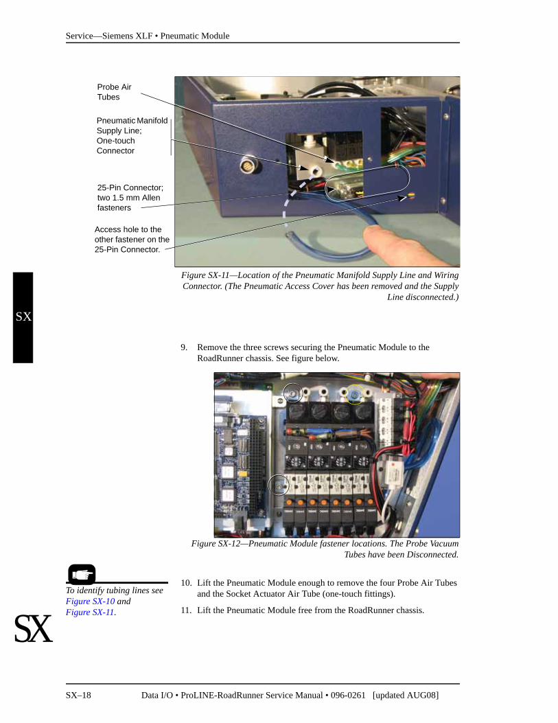
Figure SX-11—Location of the Pneumatic Manifold Supply Line and WiringConnector. (The Pneumatic Access Cover has been removed and the Supply
Line disconnected.)
9. Remove the three screws securing the Pneumatic Module to the RoadRunner chassis. See figure below.
Figure SX-12—Pneumatic Module fastener locations. The Probe VacuumTubes have been Disconnected.
10. Lift the Pneumatic Module enough to remove the four Probe Air Tubes and the Socket Actuator Air Tube (one-touch fittings).
11. Lift the Pneumatic Module free from the RoadRunner chassis.
Pneumatic Manifold Supply Line;One-touch Connector
Access hole to the other fastener on the 25-Pin Connector.
Probe AirTubes
25-Pin Connector;two 1.5 mm Allen fasteners
To identify tubing lines see Figure SX-10 and Figure SX-11.

Service—Siemens XLF • Pneumatic Module
Data I/O • ProLINE-RoadRunner Service Manual • 096-0261 [updated AUG08] SX–19
SX
SX
Reinstalling the Pneumatic Module
Installation is done in the reverse order of removal; then the following post-installation adjustments are required:
1. Reconnect the power and pressurized air.
2. Switch the power on.
3. At the Control Panel, verify proper electrical and pneumatic connec-tions as follows:
3a. Extend and retract each probe to verify correct plumbing. Robot Diagnostics » Probe X » Position » Arrow Up/Down.
3b. Enable vacuum to each probe to verify correct plumbing. Robot Diagnostics » Probe X » Vac Sense » Arrow Up/Down.
3c. Enable probe “Puff” and verify correct switching of positive air pressure at the probe tips. Robot Diagnostics » Probe 1 » Puff » Up/Down Arrow.
3d. Check the operation of the Socket Actuator. Robot Diagnostics » Socket » State » Up/Down Arrow.
4. Adjust the probe vacuum sensors.
5. Adjust probe speed.
Adjusting the Low Air Pressure Sensor
The Low Air Pressure Sensor is part of the Pneumatic Module and is set at the factory to shut off the incoming air if the pressure drops below 65 psi. If you are experiencing air pressure problems, this sensor can be adjusted as follows.
To adjust the Low Air Pressure Sensor:
1. Push the E-Stop..
2. Remove the Electronics Covers.
For step 4 see“Adjusting Probe Vacuum Sensors” on page SX-47.
For step 5 see “Adjusting and Balancing Probe Speed” on page SX-42.
For more information about removing the cov-ers see page SX-7.
Electric shock hazard. The following procedures require the Electronics Cover(s) to be removed while power is on. Only touch items described in the proce-
dures.Use caution.
WARNING!

Service—Siemens XLF • Pneumatic Module
SX–20 Data I/O • ProLINE-RoadRunner Service Manual • 096-0261 [updated AUG08]
SX
SX
3. With the power and the air on, check that the Low Air Pressure Sensor LED is lit.
4. Reduce the inlet air pressure to 0.448 MPa (65 psi).
5. With a small screwdriver rotate the sensor adjustment screw coun-ter-clockwise until the LED goes out. Then turn it clockwise just until the LED lights.
Figure SX-13—Adjusting the Low Pressure Sensor on the PneumaticModule. The arrow points to the adjustment screw. The LED is circled.
6. Replace the Electronics Covers.
7. Release the E-Stop.

Service—Siemens XLF • Pneumatic Module
Data I/O • ProLINE-RoadRunner Service Manual • 096-0261 [updated AUG08] SX–21
SX
SX
Blank page

Service—Siemens XLF • Cover Tape Module and Tensioner
SX–22 Data I/O • ProLINE-RoadRunner Service Manual • 096-0261 [updated AUG08]
SX
SX
Cover Tape Module and Tensioner
Figure SX-14—Cover Tape Module and the Tape Tensioner
If the Cover Tape Module fails to wind tape onto the reel, first check to see if the reel is full. Also, check that there is tension against the Tape Tension Roller.
If the Take-Up Reel is not full but the module is not winding tape, then the Cover Tape Module is suspect. Check for these:• loose reel not seated on the pins • loose or broken drive belt • malfunctioning motor, • malfunctioning clutch assembly or• a motor connector that is loose or disconnected• Tape Tension roller does not roll freely.You may need to remove the Control Panel Cover.
If the problem is the motor or drive belt, then the Cover Tape Module needs to be returned to Data I/O for repair. If your RoadRunner XLF is past war-ranty period, you may elect to repair it on-site if you have a certified techni-cian.
Signature:_________________________Date:_____________Company:___________________________
Tape Tensioner Roller with Sensor (hidden)
Take-Up Reel pins.
For more on the Control Panel Cover, see Figure SX-2.
Data I/O Parts Ordering InformationInstructions: 1. Copy this page. 2. Fill in your RoadRunner model and serial numbers (see the label on the chassisunder the Robotics Cover). 3. Fill in the quantity for the item(s) desired. 4. Call your local Data I/O sale representativefor part prices (optional). 5. Mail or FAX it with your purchase order to Data I/O. See the last page of this manual forcontact information.
ProLINE-RoadRunner XLF Model No.___________ Serial No.___________
Inventory Part Number Part Description Qty Price Ea. Totals
7502402001 Cover Tape Module, XLF $ $7502403001 Cover Tape Sensor Assy, XLF $ $
$ $$ $$ $

Service—Siemens XLF • Cover Tape Module and Tensioner
Data I/O • ProLINE-RoadRunner Service Manual • 096-0261 [updated AUG08] SX–23
SX
SX
Removing the Cover Tape Module
1. Turn the power off.
2. Unplug the RoadRunner power cord.
3. Remove the Robotics Cover.
4. Remove the Take-Up reel from the Cover Tape Module.
5. Remove the three screws that mount the Cover Tape Module to the RoadRunner chassis.
Figure SX-15—Location of the Cover Tape Module Mounting Screws(circled). The Take-Up Reel has been removed.
6. Disconnect the cable from the Cover Tape Module motor by pinching the clasp and pulling the connector apart.
Replacement of the Cover Tape Module is done in reverse order of removal.
Removing the Tape Tension Sensor
The Tape Tension Sensor can be replaced without removing the Tape Ten-sion Assembly. To remove the Sensor:
1. Unscrew the sensor from the assembly with a 1.5 mm hex key.
2. Remove the four screws attaching the PC Card Drive to the chassis, and slide the reader to the right and out as the cable allows.
3. Unplug the Sensor connector.
Replacement is in the reverse order.
For location of the Card Drive screws, see “PC Card Drive” on page SX-40

Service—Siemens XLF • Cover Tape Module and Tensioner
SX–24 Data I/O • ProLINE-RoadRunner Service Manual • 096-0261 [updated AUG08]
SX
SX
.
Figure SX-16—The Cover Tape Tensioner with mounting screws (circled)and Sensor screw (boxed).
Removing the Tape Tension Assembly
The Tape Tension Assembly incorporates a roller and sensor to detect if the cover tape breaks (or is not routed properly).
To remove the Tape Tension Assembly (with sensor):
1. Remove the two screws securing the assembly to the chassis with a 3 mm hex key.
2. Remove the four screws attaching the Card Drive to the chassis, and slide the reader to the right and out as the cable allows.
3. Unplug the Tape Tension Sensor connector.
Replacement is in the reverse order.
Service—Siemens XLF • Cover Tape Module and Tensioner
Data I/O • ProLINE-RoadRunner Service Manual • 096-0261 [updated AUG08] SX–25
SX
SX
blank page

Service—Siemens XLF • Conveyor Module
SX–26 Data I/O • ProLINE-RoadRunner Service Manual • 096-0261 [updated AUG08]
SX
SX
Conveyor Module
Figure SX-17—Location of Wires and Screws on the Conveyor Module
The conveyor belt, the belt motor, and the End-of-Belt Sensor make up the main parts of the Conveyor Module.
If the conveyor belt becomes creased, it will cause devices placed on the crease to be mispositioned. For this reason, a Conveyor Module with a creased or damaged belt should be immediately replaced. However, a belt can become somewhat creased from several days of inactivity. This can be easily remedied by running the RoadRunner in Dry Run mode for two min-utes (Robot Diagnostics > Run Mode > Dry Run).
The entire Conveyor Module can be removed and replaced or sent to Data I/O for repair. The End-of-Belt sensor optic can be adjusted and the Optical fiber Amplifier retaught.
Signature:_________________________Date:_____________Company:___________________________
Sensor OpticCables and Motor Wires.
Mounting Screws are circled.
Data I/O Parts Ordering InformationInstructions: 1. Copy this page. 2. Fill in your RoadRunner model and serial numbers (see the label on the chassisunder the Robotics Cover). 3. Fill in the quantity for the item(s) desired. 4. Call your local Data I/O sale representativefor part prices (optional). 5. Mail or FAX it with your purchase order to Data I/O. See the last page of this manual forcontact information.
ProLINE-RoadRunner XLF Model No.___________ Serial No.___________
Inventory Part Number Part Description Qty Price Ea. Totals
7502396001 Conveyor Module, S-XLF $ $$ $$ $$ $

Service—Siemens XLF • Conveyor Module
Data I/O • ProLINE-RoadRunner Service Manual • 096-0261 [updated AUG08] SX–27
SX
SX
Removing the Conveyor Module
1. Turn the power off.
2. Disconnect the RoadRunner XLF power cord and air supply.
3. Lift off the Robotics Cover.
4. Remove the Conveyor Module Cover.
5. Cut the cable ties securing the wires for the belt motor and sensors.
CAUTION: Optic cables are fragile and may break. Use care not to bend much.
6. Disconnect two connectors: belt motor wires and optical fiber amplifier wires by pinching the clasp open and pulling the connector apart.
Figure SX-18— Conveyor Wire Connector Locations (Circled)
7. Remove the two screws attaching the Conveyor Module to the chassis.
8. Lift the Conveyor Module free of the RoadRunner chassis.
Reinstalling the Conveyor ModuleTo reinstall the conveyor, reverse the removal steps, plus perform the follow-ing (Refer to Figure SX-18):
1. Notice the conveyor locating pin on the chassis. You may need to lift the Conveyor Module slightly to engage the pin.
2. Check that no wires are pinched between the Conveyor and the chassis.
For more information, see “Removing the Conveyor Module Cover” on page SX-8.
Locating pin is visible after Conveyor Module is removed.
For Conveyor screw loca-tions see Figure SX-17.

Service—Siemens XLF • Conveyor Module
SX–28 Data I/O • ProLINE-RoadRunner Service Manual • 096-0261 [updated AUG08]
SX
SX
3. Set the conveyor height as follows:
3a. With the RoadRunner in its normal upright position and the con-veyor fasteners snug but not tightened, move the PNP Head over the conveyor belt.
3b. Place your thinnest device on the belt below Probe 1.
3c. Lower Probe 1 fully (pushing on the nut directly above the probe stem). With the probe fully extended, adjust the conveyor height so there is approximately a 1 mm gap between the probe tip and the device on the belt. Then tighten the conveyor fasteners.
3d. Recheck the height after tightening the fasteners.
Adjusting the End-of-Belt Sensor
The End-of-Belt Sensor Optic stops the conveyor belt when parts reach the pick point. The optic sends a beam across the pick point between two fiber optic sensors. When a device breaks the beam, the End-of-Belt Optic stops the belt. The most likely indication that the End-of-Belt Optic is out of adjustment or broken, is that parts fall off the end of the conveyor.
If parts are falling off the end of the conveyor, first test to make sure the Optical fiber Amplifier is functioning (see “Testing . . .” below). If the sen-sor is functioning, but parts are still passing the pick point, reteach the Opti-cal fiber Amplifier.
Testing the End-of-Belt Sensor
1. From the top level menu select Robot Diagnostics.
2. Select Belt.
3. Select Pick Sensor.
4. Put your finger at the SMT pick point to block the sensor optic.
5. The Control Panel display will show Pick Sensor: 1 whenever your fin-ger is blocking the beam, and Pick Sensor: 0 when not blocked.
Figure SX-19—Testing the End-of-Belt Sensor (The Conveyor Cover neednot be removed.)
Push probe here with finger.

Service—Siemens XLF • Conveyor Module
Data I/O • ProLINE-RoadRunner Service Manual • 096-0261 [updated AUG08] SX–29
SX
SX
6. If Pick Sensor: 1 is not displayed when the beam is blocked, check to make sure that all the sensor wires and fiber optics are connected prop-erly.
6a. If Pick Sensor:1 still does not display, then the Conveyor Module needs to be replaced.
6b. If Pick Sensor:1 does display, see “Reteaching the End-of-Belt optical fiber amplifier,” below.
Reteaching the End-of-Belt Optical Fiber Amplifier
1. Remove the Conveyor Module Cover.
2. Clean the conveyor belt: with isopropyl alcohol on a lint-free cloth, clean the exposed portion of the belt and then dry it.
3. Press the Emergency Stop button—the conveyor belt can now be rotated by hand.
4. Rotate the belt (toward SMT machine) and clean and dry this section.
5. Manually rotate the belt so that the optical fiber amplifier displays its highest value.
6. Place a device on the SMT pick point so it blocks the optic beam.
7. Push Set on the optical fiber amplifier.
Figure SX-20—Reteaching the End-of-Belt Sensor
8. Remove the device from the belt and then rotate the belt (toward SMT machine) until the optical fiber amplifier displays its lowest value.
9. Push Set on the optical fiber amplifier again.
NOTE: In general, the End-of-Belt Optical fiber Amplifier should display a number less than 21 when a device is present at the SMT pick point and greater than 90 when no device is present. If it is not possible to achieve numbers less than 21 and greater than 90 by adjusting the optic beam, the conveyor module must be replaced. (The optical fiber amplifier must always operate in “Turbo” mode.)
The Optical fiber Amplifier is mounted in the Conveyor Module. See Figure SX-20.
End-of-Belt Optical fiber Amplifier
End-of-Belt Sensor Optic
For details on setting the Optical fiber Amplifier see the label on the inside of the Conveyor Cover shown in Figure SX-21.

Service—Siemens XLF • Conveyor Module
SX–30 Data I/O • ProLINE-RoadRunner Service Manual • 096-0261 [updated AUG08]
SX
SX
Figure SX-21—End-of-Belt Optical fiber Amplifier Label on theConveyor Cover

Service—Siemens XLF • Conveyor Module
Data I/O • ProLINE-RoadRunner Service Manual • 096-0261 [updated AUG08] SX–31
SX
SX
Blank page

Service—Siemens XLF • Reject Bin
SX–32 Data I/O • ProLINE-RoadRunner Service Manual • 096-0261 [updated AUG08]
SX
SX
Reject Bin
Figure SX-22—The Reject Bin (outlined)
The Reject Bin is not fastened in, and lifts out of the RoadRunner XLF. Lift up and then out.
The Reject Bin-Full Sensor senses when the bin is full and requires empty-ing. The Reject Bin-Present sensor senses the bin’s presence. The sensors are attached to the Reject Bin Bracket.
Signature:_________________________Date:_____________Company:___________________________
Data I/O Parts Ordering InformationInstructions: 1. Copy this page. 2. Fill in your RoadRunner model and serial numbers (see the label on the chassisunder the Robotics Cover). 3. Fill in the quantity for the item(s) desired. 4. Call your local Data I/O sale representativefor part prices (optional). 5. Mail or FAX it with your purchase order to Data I/O. See the last page of this manual forcontact information.
ProLINE-RoadRunner XLF Model No.___________ Serial No.___________
Inventory Part Number Part Description Qty Price Ea. Totals
6074132001 Reject Bin, XLF $ $7090551003 Reject Bin-Full Sensor, XLF $ $7090667001 Reject Bin-Present Sensor, XLF $ $
$ $$ $

Service—Siemens XLF • Reject Bin
Data I/O • ProLINE-RoadRunner Service Manual • 096-0261 [updated AUG08] SX–33
SX
SX
Removing the Reject Bin Sensors
1. Turn the power off.
2. Disconnect the power cord and air supply.
3. Lift off the Robotics Cover.
4. Push the head away from the Reject Bin area if necessary.
5. Lift out the Reject Bin.
6. Remove the Electronics Cover.
7. Unscrew the two screws securing the Reject Bin Bracket to the chassis with a 3 mm hex key.
Figure SX-23—Reject Bin Sensors with Reject Bin Bracket Screw Locationscircled. The left screw requires a ball-end hex key. The Reject Bin has been
removed.
8. Unplug the Reject Bin Full optic sensor wires from the Interconnect Panel at J1C.
9. Unplug the Reject Bin Present Sensor wires from the Interconnect Panel at J1C2 and cut the Nylon cable tie (as necessary).
10. Carefully lift out the Reject Bin Bracket with sensors.To remove the sensors:
11. Unscrew one screw through each optic sensor with a 1.5 mm hex key.
12. Unscrew two screws through the Bin Present Sensor with a 1.5 mm hex key.
For more information, see “Removing the Electronic Covers” on page SX-7.
Reject Bin-Full Sensors (here and directly opposite, mostly hidden).
Reject Bin-Present Sensor

Service—Siemens XLF • Reject Bin
SX–34 Data I/O • ProLINE-RoadRunner Service Manual • 096-0261 [updated AUG08]
SX
SX
Figure SX-24—Connectors J1C (boxed) and J1C2 (circled).
To install the Reject Bin Sensors and bracket, reverse the removal proce-dures:• Reinstall the Sensors and the Reject Bin Bracket• Reinstall the Electronics Cover.
CAUTION: Ensure that the neither the Reject Bin nor the sensor wires contact the Conveyor Belt. Verify this when finished by rotating the Conveyor Belt by hand and watching closely.

Service—Siemens XLF • Reject Bin
Data I/O • ProLINE-RoadRunner Service Manual • 096-0261 [updated AUG08] SX–35
SX
SX
blank page

Service—Siemens XLF • Control Panel Module
SX–36 Data I/O • ProLINE-RoadRunner Service Manual • 096-0261 [updated AUG08]
SX
SX
Control Panel Module
Figure SX-25—Control Panel Module, front and back
The Control Panel Module consists of the Emergency Stop button, the Indi-cator Lamps, Control Panel buttons and LCD screen. If any of the compo-nents in the Control Panel Module are not functioning correctly, check the wiring connections.
If components are still not functioning after connections are tested, return the Control Panel Module to Data I/O for repair.
NOTE: Do not disassemble the Control Panel Module. If a compo-nent is not functioning, send the entire Control Panel Module back to Data I/O.
Signature:_________________________Date:_____________Company:___________________________
Data I/O Parts Ordering InformationInstructions: 1. Copy this page. 2. Fill in your RoadRunner model and serial numbers (see the label on the chassisunder the Robotics Cover). 3. Fill in the quantity for the item(s) desired. 4. Call your local Data I/O sale representativefor part prices (optional). 5. Mail or FAX it with your purchase order to Data I/O. See the last page of this manual forcontact information.
ProLINE-RoadRunner XLF Model No.___________ Serial No.___________
Inventory Part Number Part Description Qty Price Ea. Totals
7502397001 Control Panel Module, XLF $ $$ $$ $$ $

Service—Siemens XLF • Control Panel Module
Data I/O • ProLINE-RoadRunner Service Manual • 096-0261 [updated AUG08] SX–37
SX
SX
Removing the Control Panel Module
1. Turn the power off.
2. Disconnect the RoadRunner power cord and air supply.
3. Remove the Robotics Cover.
4. Remove the small corner panel by removing three screws with a 2 mm hex key. See figure below.
Figure SX-26—Corner Panel Cover with screw locations circled.
5. Remove the four screws on the face of the Control Panel with a 2 mm hex key.
6. Lift the Control Panel Module up enough to see the underside.
7. Unplug the Control Panel Ribbon Cable from the connector.
8. Follow the wires for the Emergency Stop button to their end connector (near the linear Stage motor) and disconnect it. You may need to cut some Nylon cable ties.
9. Carefully pull the cable up and free with the Control Panel.
Figure SX-27—Location of Connector on the Control Panel.
For more information, see “Removing the Robotics Cover” on page SX-7.
Keyboard Interface connector
Emergency Stop Button wires

Service—Siemens XLF • Control Panel Module
SX–38 Data I/O • ProLINE-RoadRunner Service Manual • 096-0261 [updated AUG08]
SX
SX
Figure SX-28—Bundle of wires includes the E-Stop Cable connector.
Replacement is the in the reverse order of removal. When reassembled, verify the proper operation of the following:
• Display• Keypad• Emergency Stop

Service—Siemens XLF • Control Panel Module
Data I/O • ProLINE-RoadRunner Service Manual • 096-0261 [updated AUG08] SX–39
SX
SX
blank page

Service—Siemens XLF • PC Card Drive
SX–40 Data I/O • ProLINE-RoadRunner Service Manual • 096-0261 [updated AUG08]
SX
SX
PC Card Drive
Figure SX-29—PC Card Drive (with card inserted). Screw locations arecircled. The Electronics Covers have been removed.
The PC Card drive (also called a Card Reader/Writer) accepts Type II PCMCIA cards. If you experience problems, first confirm that the PC card you are using is good. Test the Card Drive with a card that is known to func-tion correctly. Test all connections. If the PC Drive is still not functioning, remove it and return it to Data I/O for repair.
Trouble with PC Cards is often that the card has become corrupt or that it was incorrectly formatted (must be FAT 16, not FAT 32).
Signature:_________________________Date:_____________Company:___________________________
Data I/O Parts Ordering InformationInstructions: 1. Copy this page. 2. Fill in your RoadRunner model and serial numbers (see the label on the chassisunder the Robotics Cover). 3. Fill in the quantity for the item(s) desired. 4. Call your local Data I/O sale representativefor part prices (optional). 5. Mail or FAX it with your purchase order to Data I/O. See the last page of this manual forcontact information.
ProLINE-RoadRunner XLF Model No.___________ Serial No.___________
Inventory Part Number Part Description Qty Price Ea. Totals
7502401001 PC Card Drive (reader/writer), XLF $ $$ $$ $$ $
Service—Siemens XLF • PC Card Drive
Data I/O • ProLINE-RoadRunner Service Manual • 096-0261 [updated AUG08] SX–41
SX
SX
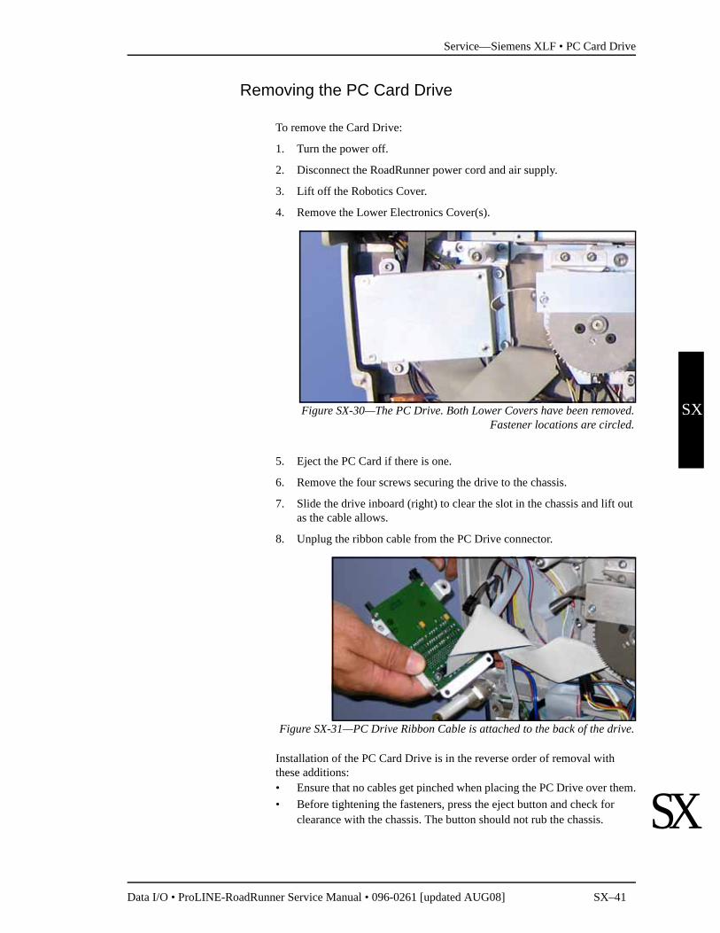
Removing the PC Card Drive
To remove the Card Drive:
1. Turn the power off.
2. Disconnect the RoadRunner power cord and air supply.
3. Lift off the Robotics Cover.
4. Remove the Lower Electronics Cover(s).
Figure SX-30—The PC Drive. Both Lower Covers have been removed.Fastener locations are circled.
5. Eject the PC Card if there is one.
6. Remove the four screws securing the drive to the chassis.
7. Slide the drive inboard (right) to clear the slot in the chassis and lift out as the cable allows.
8. Unplug the ribbon cable from the PC Drive connector.
Figure SX-31—PC Drive Ribbon Cable is attached to the back of the drive.
Installation of the PC Card Drive is in the reverse order of removal with these additions:• Ensure that no cables get pinched when placing the PC Drive over them.• Before tightening the fasteners, press the eject button and check for
clearance with the chassis. The button should not rub the chassis.
Service—Siemens XLF • Pick and Place Head
SX–42 Data I/O • ProLINE-RoadRunner Service Manual • 096-0261 [updated AUG08]
SX
SX
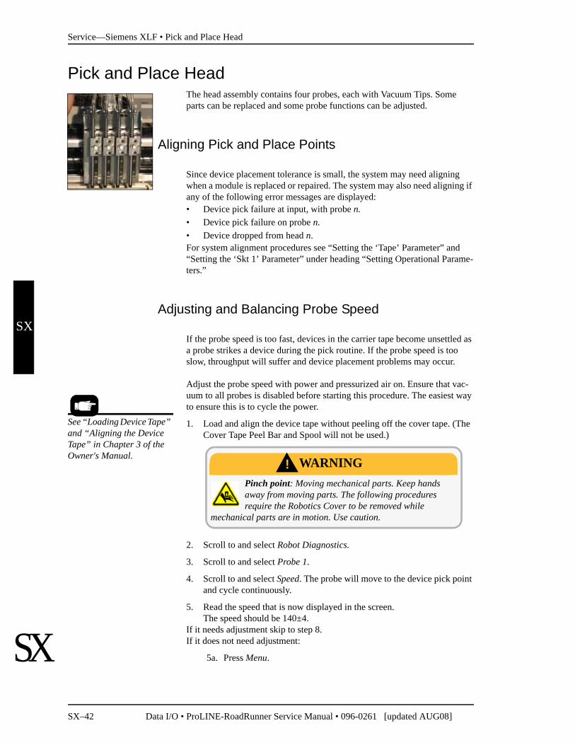
Pick and Place HeadThe head assembly contains four probes, each with Vacuum Tips. Some parts can be replaced and some probe functions can be adjusted.
Aligning Pick and Place Points
Since device placement tolerance is small, the system may need aligning when a module is replaced or repaired. The system may also need aligning if any of the following error messages are displayed:• Device pick failure at input, with probe n.• Device pick failure on probe n.• Device dropped from head n.For system alignment procedures see “Setting the ‘Tape’ Parameter” and “Setting the ‘Skt 1’ Parameter” under heading “Setting Operational Parame-ters.”
Adjusting and Balancing Probe Speed
If the probe speed is too fast, devices in the carrier tape become unsettled as a probe strikes a device during the pick routine. If the probe speed is too slow, throughput will suffer and device placement problems may occur.
Adjust the probe speed with power and pressurized air on. Ensure that vac-uum to all probes is disabled before starting this procedure. The easiest way to ensure this is to cycle the power.
1. Load and align the device tape without peeling off the cover tape. (The Cover Tape Peel Bar and Spool will not be used.)
2. Scroll to and select Robot Diagnostics.
3. Scroll to and select Probe 1.
4. Scroll to and select Speed. The probe will move to the device pick point and cycle continuously.
5. Read the speed that is now displayed in the screen.The speed should be 140±4.
If it needs adjustment skip to step 8.If it does not need adjustment:
5a. Press Menu.
See “Loading Device Tape” and “Aligning the Device Tape” in Chapter 3 of the Owner's Manual.
Pinch point: Moving mechanical parts. Keep hands away from moving parts. The following procedures require the Robotics Cover to be removed while
mechanical parts are in motion. Use caution.
WARNING!
Service—Siemens XLF • Pick and Place Head
Data I/O • ProLINE-RoadRunner Service Manual • 096-0261 [updated AUG08] SX–43
SX
SX
5b. Scroll to and select the next probe.
5c. Repeat from step 4 for each probe.
6. Remove the Electronics Cover and the Conveyor Module Cover.
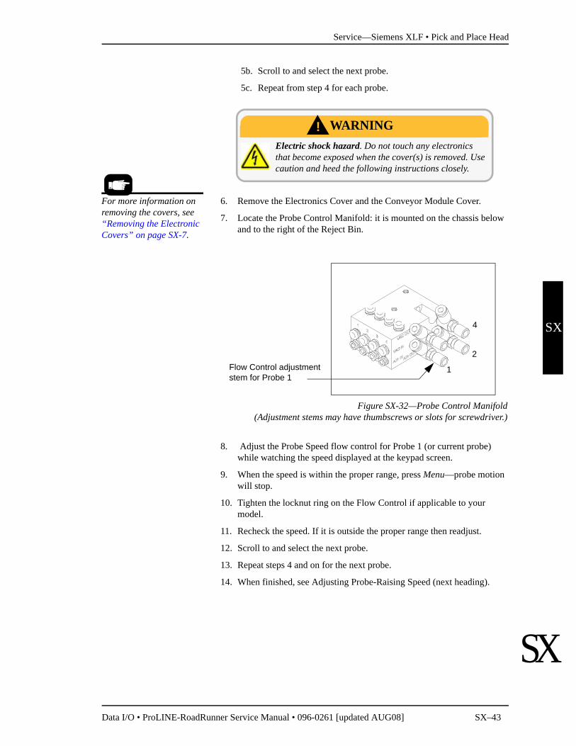
7. Locate the Probe Control Manifold: it is mounted on the chassis below and to the right of the Reject Bin.
Figure SX-32—Probe Control Manifold(Adjustment stems may have thumbscrews or slots for screwdriver.)
8. Adjust the Probe Speed flow control for Probe 1 (or current probe) while watching the speed displayed at the keypad screen.
9. When the speed is within the proper range, press Menu—probe motion will stop.
10. Tighten the locknut ring on the Flow Control if applicable to your model.
11. Recheck the speed. If it is outside the proper range then readjust.
12. Scroll to and select the next probe.
13. Repeat steps 4 and on for the next probe.
14. When finished, see Adjusting Probe-Raising Speed (next heading).
Electric shock hazard. Do not touch any electronics that become exposed when the cover(s) is removed. Use caution and heed the following instructions closely.
WARNING!
Flow Control adjustment stem for Probe 1
1
2
4
For more information on removing the covers, see “Removing the Electronic Covers” on page SX-7.

Service—Siemens XLF • Pick and Place Head
SX–44 Data I/O • ProLINE-RoadRunner Service Manual • 096-0261 [updated AUG08]
SX
SX
Adjusting Probe-Raising Speed
NOTE: Probe lowering speed should be set first. See “Adjusting and Balancing Probe Speed” on page SX-42.
If the probe-raising speed is too fast, devices may rotate excessively after a pick operation and cause alignment problems; devices may even fall off the probes. It could also bend the motion limit pin on the PNP Head.
To adjust the probe-raising speed:
1. Load and align the device tape without peeling off the cover tape. (The Cover Tape Peel Bar and Spool will not be used.)
2. Scroll to and select Robot Diagnostics.
3. Scroll to and select Probe 1.
4. Scroll to and select Speed. The probe will move to the device pick point and cycle continuously.
Figure SX-33—The in-line flow controls for adjusting the Probe Speed.Probe numbers are stamped on the manifold.
5. Watch the probe to observe the probe-raising speed. The probe should be fully up the very instant that the head jogs back and forth a couple millimeters.
Pinch point: Moving mechanical parts. Keep hands away from moving parts. The following procedures require the Robotics Cover to be removed while
mechanical parts are in motion. Use caution.
WARNING!
Probe-Raising Speed flow controls are in-line.
Probe-Lowering Speed flow controls are on the Interface manifold.
For more information . . . See “Loading Device Tape” and “Aligning the Device Tape” in Chapter 3 of the Owner’s Manual.

Service—Siemens XLF • Pick and Place Head
Data I/O • ProLINE-RoadRunner Service Manual • 096-0261 [updated AUG08] SX–45
SX
SX
If the probe is fully up too soon (before the head jogs) or too late (after the head jogs), remove the Electronic Cover and the Conveyor Module Cover.
6. Loosen the locknut ring on the in-line Flow Control for Probe 1 (or cur-rent probe).
7. Manually adjust the speed by hand using the knob on the in-line flow control for Probe 1 raising speed (see figure above). Adjust the probe-raising speed until it synchronizes with the head jog.
8. Tighten the locknut ring.
9. Press Menu to deselect the current probe.
10. Scroll to and select the next probe.
11. Repeat these steps (from step 4 and on) for each probe.
12. When finished, replace both covers and remove the device tape.
For more information see “Covers” on page SX-6.

Service—Siemens XLF • Pick and Place Head
SX–46 Data I/O • ProLINE-RoadRunner Service Manual • 096-0261 [updated AUG08]
SX
SX
Resetting the Pick Delay and Travel Delay Times
The delay times do not change and do not usually require adjustment. The factory-set values are indicated in the following flow charts.
Figure SX-34—Pick and Place Delay Flow Charts
NOTE: Changes to these values are not recommended.
These values only affect the internal verification delay time, as indicated in the flow charts. To reset delay times:
1. From the top level menu on the display, select Operation.
2. Scroll to and select Probes.
3. Scroll to and select the setting you wish to adjust.
4. Use the Arrow Up and Arrow Down buttons to change the setting.
5. When finished, select Menu.
StartPick
Part on Tip?
Extend Probe.
Apply "Travel" delay.
No
Display error messageYes
Probe Down? Display error messageNo
Yes
Apply "Pick" delay.
Raise probe.
No
Apply "Travel" delay.
Probe Up? Display error messageNo
Yes
Part on tip?
Done
Yes
Part Present = TRUENo
Display "dropped part" error message
Yes
No
Turn vacuum off.
Factory setting is 250 ms
Factory setting is 200 ms
Factory setting is 250 ms
go to pickretry sequence
(not shown)
Part Present? Yes Part Present = TRUE
Turn Vacuum On
StartPlace
Part on Tip?
Extend Probe.
Apply Travel delay
Display error message
Probe Down? Display error messageNo
Turn Vacuum off
Yes
Raise probe
Apply Puff duration
Apply probe Travel delay
Probe Up? Display error messageNo
Yes
Factory setting is 250 ms
Factory setting is 130 ms
Factory setting is 250 ms
No
Yes
Place in reject bin?
No
Apply puff
go to A
Yes
A
go to "Check Probe for Device"(not shown)
Apply Place delay
Factory setting is 100 ms
Turn puff off
Place Delay Pick Delay

Service—Siemens XLF • Pick and Place Head
Data I/O • ProLINE-RoadRunner Service Manual • 096-0261 [updated AUG08] SX–47
SX
SX
Adjusting Probe Vacuum Sensors
1. Select Menu until you reach the top menu level and select Robot Diag-nostics.
1a. Scroll to and select Probe 1.
1b. Scroll to and select Vacuum.
1c. Press the Up Arrow to enable the probe.
2. Remove the Electronics Cover.
2a. Turn the vacuum sensor adjust screw for Probe 1 (the first adjust-ment block) counter-clockwise until the red LED adjacent to the adjustment screw illuminates.
Figure SX-35—Pneumatic Valve Block. When the vacuum for Probe 1 isenabled, the two small LEDs on the solenoids (white arrows) for Probe 1
will be unlit.
2b. Turn the vacuum sensor adjust screw for Probe 1 clockwise until the red LED goes out. Continue turning the screw one more revo-
Electric shock hazard. The following procedures require the Electronics Cover(s) to be removed while power is on. Only touch items described in the proce-
dures.Use caution.
WARNING!
Solenoid switches for Probe 1(typical)
Vacuum Sensor Adjustment Screw for Probe 1(typical)
Adjustment LED for Probe 1(typical)

Service—Siemens XLF • Pick and Place Head
SX–48 Data I/O • ProLINE-RoadRunner Service Manual • 096-0261 [updated AUG08]
SX
SX
lution clockwise. Release the probe allowing it to resume the up position.
3. Select Menu until you reach the top menu level again and select Robot Diagnostics.
3a. Scroll to and select Probe 1.
3b. Scroll to and select Vacuum.
3c. Press the Down Arrow to disable the probe.
4. Repeat steps 1 through 3 for each probe.
5. Re-install the Cover when finished.

Service—Siemens XLF • Pick and Place Head
Data I/O • ProLINE-RoadRunner Service Manual • 096-0261 [updated AUG08] SX–49
SX
SX
blank page

Service—Siemens XLF • Pick and Place Head
SX–50 Data I/O • ProLINE-RoadRunner Service Manual • 096-0261 [updated AUG08]
SX
SX
Removing the PNP Head
Figure SX-36—The PNP Head Mounting Screws (circled).
If you receive error messages relating to the Pick and Place (PNP) function, refer to the troubleshooting chart in the Owner’s Manual.
If you experience trouble with the Pick and Place Head that is not covered in this manual, remove the head and send it to Data I/O Customer Service for repair or replacement. For example, a bent probe would require the PNP Head to be replaced.
Removal procedures are on the following page.
Signature:_________________________Date:_____________Company:___________________________
Data I/O Parts Ordering InformationInstructions: 1. Copy this page. 2. Fill in your RoadRunner model and serial numbers (see the label on the chassisunder the Robotics Cover). 3. Fill in the quantity for the item(s) desired. 4. Call your local Data I/O sale representativefor part prices (optional). 5. Mail or FAX it with your purchase order to Data I/O. See the last page of this manual forcontact information.
ProLINE-RoadRunner XLF Model No.___________ Serial No.___________
Inventory Part Number Part Description Qty Price Ea. Totals
2890014005 Pick and Place Head $ $2880019001 Probe Tip $ $
$ $$ $

Service—Siemens XLF • Pick and Place Head
Data I/O • ProLINE-RoadRunner Service Manual • 096-0261 [updated AUG08] SX–51
SX
SX
To remove the Pick and Place Head:
1. Turn the power off.
2. Disconnect the RoadRunner power cord and air supply.
3. Remove the Robotics Cover.
4. Label and disconnect the tube from the top of each probe.
5. Remove two socket head cap screws attaching the head to the ball screw carriage [3 mm hex key].
6. Lightly pull the head a couple of centimeters away from the carriage.
7. Label and remove four pneumatic tubes with fittings from the back of the head with a slotted screwdriver. Note that each has a washer.
Figure SX-37—The four fittings on the back of the PNP Head. (The Headhas been unbolted from the Linear Stage).
8. Remove two Head Bracket screws from each side of the head [2 mm hex key].
To reinstall a PNP Head, reverse the steps for removal and perform the fol-lowing:
1. Install the four fittings onto the new head—the tubes are still attached. Ensure that each has a gasket.
2. Install the head Bracket onto the head.
3. Attach the tubes to the probes.
4. Install the head to the Linear stage with the two socket screws. Use Loc-tite.
5. Perform the “Linear Stage Reinstallation Verification” procedure.
For PNP Head screw loca-tions see Figure SX-36.
Tube Fitting and Gasket.
For more information, see the “Linear Stage Installa-tion Verification” on page SX-66.

Service—Siemens XLF • Programmer Module
SX–52 Data I/O • ProLINE-RoadRunner Service Manual • 096-0261 [updated AUG08]
SX
SX
Programmer Module
Figure SX-38—Programmer Module with mounting screws circled.
The Programmer Module consists of the WaveForm Board, Main Controller Board, BackPlane Board, the Socket Adapter, and the Socket Actuator that opens and closes the programmer sockets.
If Programmer Module sockets become worn, the Socket Adapter needs attention. The Socket Adapter needs cleaning when yield drops, and needs replacing when cleaning fails to boost yield. If replacing the Socket Adapter does not solve problems in the Programmer Module, see “Diagnosing with the Adapter Board” in the Maintenance Chapter of the Owner's Manual, or contact Data I/O for Programmer Module replacement or repair.
Signature:_________________________Date:_____________Company:___________________________
1-PCMCIA Cable Board
2- Ribbon Cable Connector J4
3- Cable Connector J3
4- Actuation air tube
5- Actuation Flow Control Valve
4
1 2
3
5
For more information, see “Changing the Socket Adapter” in Chapter 3 of the Owner's Manual.
Data I/O Parts Ordering InformationInstructions: 1. Copy this page. 2. Fill in your RoadRunner model and serial numbers (see the label on the chassisunder the Robotics Cover). 3. Fill in the quantity for the item(s) desired. 4. Call your local Data I/O sale representativefor part prices (optional). 5. Mail or FAX it with your purchase order to Data I/O. See the last page of this manual forcontact information.
ProLINE-RoadRunner XLF Model No.___________ Serial No.___________
Inventory Part Number Part Description Qty Price Ea. Totals
7502398001 FC II Programmer, XLF $ $6950019001 Programmer Alignment Tool $ $
$ $$ $$ $

Service—Siemens XLF • Programmer Module
Data I/O • ProLINE-RoadRunner Service Manual • 096-0261 [updated AUG08] SX–53
SX
SX
Removing the Programmer Module
NOTE: Only technicians who have taken the ProLINE-RoadRunner Service training course should attempt to remove the Programmer Module.
NOTE: A Programmer Alignment Tool is recommended from Data I/O to reinstall the Programmer Module. See the order form on the previous page. (This tool is a part of the Spares Kit on page SX-72.)
1. Turn the power off.
2. Disconnect the RoadRunner power cord and air supply.
3. Lift off the Robotics Cover.
4. Remove the Lower Electronics Cover(s).
5. Move the PNP Head away from the programmer.
6. Remove the Actuator Plate by sliding it out of the bracket.
7. Optional: Remove the Socket Adapter.
8. Lift out the Reject Bin.
9. Disconnect Cable J3 by pulling the connector straight out.
Figure SX-39—PCMCIA Cable Board [A] has been removed from theProgrammer Module (squares), the air tube [B] disconnected, and J3 and
J4 cables unplugged.
See “Changing the Socket Adapter” in Chapter 3 of the Owner's Manual.
A-PCMCIA Cable Board
B- Actuation air tube
1 Cable2 Connector
BA
J41
J32
J42
J31

Service—Siemens XLF • Programmer Module
SX–54 Data I/O • ProLINE-RoadRunner Service Manual • 096-0261 [updated AUG08]
SX
SX
CAUTION: Ribbon Cables might get damaged if pulled or pinched. Cable damage is often not visible. Try to pull cables by the connector only.
10. Disconnect Ribbon Cable J4 by pulling the connector straight out and move the cable out of the way.
11. Disconnect the Actuation Air Tube from the exhaust fitting. It is a One-Touch fitting.
12. Remove the PCMCIA Cable Board from the Programmer Module by removing the four screws with a 2 mm hex key and then unplugging it (pulling up) from the board below. THE RIBBON CABLE IS NOT REMOVABLE FROM THIS PCB. Slide the board out of the way.
13. Remove four screws securing the Programmer Module to the chassis using a 2.5 mm hex key.
14. Unplug the Ethernet Cable (701-3215) connector and the Serial RJ45 (Motion Controller) connector from the left side ot the Programmer Module. It may be helpful to pull the Module part way out to access them.
15. Unplug the Actuation Sensor cable JC5 from the Interconnect Panel by pinching the clasp on top so it opens like a clothespin and pulling the connector.
Figure SX-40—Cable Interconnect Panel with the Cable JC5 and Sensorhighlighted.
16. Lift the Programmer Module out from the chassis.
Reinstalling the Programmer ModuleTo reinstall a Programmer Module, perform the following steps:
Cables are identified in Figure SX-39 above.
For air fitting information see Figure SX-9 on page SX-17.
Programmer Module screw locations are indicated in Figure SX-38.
Actuator Position Sensor
Cable J5C

Service—Siemens XLF • Programmer Module
Data I/O • ProLINE-RoadRunner Service Manual • 096-0261 [updated AUG08] SX–55
SX
SX
1. Plug the Ethernet Cable and RJ45 Motion Control Cable into the left side of the Module.
2. Reinstall a Programmer Module ensuring that no wires or hoses are pinched, and tighten the four screws.
3. Reconnect the air tube.
4. Reinstall all cable connectors.
5. Plug in the PCMCIA Cable PCB and install the four screws.
6. Reinstall the Reject Bin.
Align the Programmer Module as described below before completing rein-stallation.
Aligning the Programmer ModuleAlign the Programmer Module as follows:
Figure SX-41—The Programmer Module Alignment Tool Installed on theProgrammer in place of a Socket Adapter. (PROBE TIPS MUST BE
REMOVED PRIOR TO ALIGNMENT PROCEDURE.)
CAUTION: Chassis might get damaged. For this procedure, loosen the Programmer Module mounting screws (two upper screws) before each attempt to adjust the Programmer Alignment Screws.
1. Install the Programmer Alignment Tool (sales part number is PRO-GRAMMER ALIGNMENT TOOL) onto the Programmer Module in place of a socket adapter.
2. Remove the rubber tip from Probe 1 and extend Probe 1 into the align-ment tool hole #1. If the probe passes through the hole easily, then the left side of the programmer is properly aligned—skip to step 3.
2a. If Probe 1 does not pass through easily, loosen the upper left Pro-grammer Module mounting screw two revolutions.
Push probe here with finger.

Service—Siemens XLF • Programmer Module
SX–56 Data I/O • ProLINE-RoadRunner Service Manual • 096-0261 [updated AUG08]
SX
SX
2b. Adjust the left Position Adjustment set screw (adjacent to the mounting screw) with a 2 mm hex key so that the probe does pass through easily. Turn the screw clockwise to move the module away from the chassis.
2c. When done, tighten the upper left Programmer Module screw.
Figure SX-42—Programmer Module Alignment Screw. (the Left Hand Screwis not shown)
3. Remove the rubber tip from Probe 4 and extend it into the alignment tool hole #4. If the probe passes through the hole easily, then the right side of the programmer is properly aligned—skip to step 4.
3a. If probe 4 does not pass through easily, loosen the upper right Pro-grammer Module mounting screw two revolutions.
3b. Adjust the right Position Adjustment set-screw accordingly.
3c. When done, tighten the upper right programmer mounting screw.
4. Retest. If the module requires further adjustment, be sure to loosen the left or right mounting screw first.
5. Remove the Alignment Tool.
Adjusting the Actuation SpeedThe programmer actuation speed needs to be adjusted so that the sockets open without being slammed by the Actuator Plate. If it is too fast, causing a hard landing, it could damage sockets or cause devices to bounce.
1. Install a Socket Adapter and Actuator Plate.
2. Plug in the AC Power cable.
3. Connect external air source ensuring that it is set to approximately 5.17 Bars (75 PSI).
4. Press the Emergency Stop button to prevent the PNP Head from mov-ing.

Service—Siemens XLF • Programmer Module
Data I/O • ProLINE-RoadRunner Service Manual • 096-0261 [updated AUG08] SX–57
SX
SX
CAUTION: Pinch hazard. Keep hands and fingers away from the PNP Head, Gantry lead screw, and programmer actuator.
The E-Stop does not stop the programmer from actuating—opening and closing the sockets.
CAUTION: Shock hazard. The E-Stop does not stop electrical flow to internal electronics.
5. Insert a job card with Supervisor authority and switch the power on.
6. Locate the Actuation Flow Control and adjust it counter-clockwise to full open, then turn it clockwise 2-1/2 revolutions.
7. At the Control Panel, press Menu. Then scroll to and select Robot Diagnostics > Socket > State. After selecting the State command a dot, or bullet, appears next to it. Then the Down Arrow and Up Arrow buttons will actuate the programmer. KEEP FINGERS AWAY FROM THE PROGRAMMER AND ACTUATOR PLATE.
8. Actuate the programmer and watch the speed. If the actuator appears to hit the sockets too hard, loosen the locking ring and adjust the flow con-trol and then retry. Use the flow control to soften the impact. However, too slow and it may cause timing problems as well as reduced through-put.
9. Retighten the locking ring on the flow control.
Reinstall all RoadRunner covers.
To locate the Actuation Flow Control, see Figure SX-38 on page SX-52.

Service—Siemens XLF • NVRAM Battery
SX–58 Data I/O • ProLINE-RoadRunner Service Manual • 096-0261 [updated AUG08]
SX
SX
NVRAM Battery
Figure SX-43—The Programmer with Ribbon Cable J4 disconnected. TheNVRAM Battery is on the far side of the next board down (dashed square).
Screws for the PCMCIA Board are circled.
RoadRunner uses a lithium battery to power the non-volatile read-only memory (NVRAM). If information stored in NVRAM is lost, RoadRunner will not function correctly. If RoadRunner displays this error message: NVRAM Battery Failed, NVRAM data will be lost when RoadRunner is switched off and the battery needs to be replaced.
After a new battery has been installed in RoadRunner, perform the simple procedure that follows the battery replacement instructions to reteach the PNP Head positions, the Socket Status, Network Settings, and the time and date.
It takes approximately 40 minutes to replace the battery and an additional 20 minutes to reteach the system.
Signature:_________________________Date:_____________Company:___________________________
Data I/O Parts Ordering InformationInstructions: 1. Copy this page. 2. Fill in your RoadRunner model and serial numbers (see the label on the chassisunder the Robotics Cover). 3. Fill in the quantity for the item(s) desired. 4. Call your local Data I/O sale representativefor part prices (optional). 5. Mail or FAX it with your purchase order to Data I/O. See the last page of this manual forcontact information.
ProLINE-RoadRunner XLF Model No.___________ Serial No.___________
Inventory Name Part Description Qty Price Ea. Totals
4210001001 NVRAM Battery $ $$ $$ $

Service—Siemens XLF • NVRAM Battery
Data I/O • ProLINE-RoadRunner Service Manual • 096-0261 [updated AUG08] SX–59
SX
SX
Removing the NVRAM Battery
The battery is an integral part of the PowerCap Module. The entire PowerCap cap must be replaced. The PowerCap Module is located on the back side of the RPX_LITE circuit board.
1. Turn the power off.
2. Disconnect the RoadRunner power cord and air supply.
3. Lift off the Robotics Cover.
4. Remove the Lower Electronics Cover(s).
5. Unplug Ribbon cable J4 from the Programmer Module and move it out of the way. See figure below.
6. Remove the PCMCIA PCB by removing four socket-head cap screws and lifting the PCB up. Then pull it down and aside—the ribbon cable is not removable from the PCB. For best access, disconnect the air tube from the in-line exhaust valve. See the next two figures below.
Figure SX-44—The Programmer with Ribbon Cable J4 disconnected. (Inthe previous figure on page SX-58, the PCMCIA Board screws are circled.)
7. Remove four socket-head screws securing the RPX_LITE board to the Waveform PCB and lift the board up. Then pull it down and aside— cables are still attached. See figures below.
8. Turn the board over and locate the PowerCap Module.
For PCMCIA PCB screw locations, see Figure SX-42.
Ribbon Cable J4 has been unplugged from the connector (boxed).

Service—Siemens XLF • NVRAM Battery
SX–60 Data I/O • ProLINE-RoadRunner Service Manual • 096-0261 [updated AUG08]
SX
SX
Figure SX-45—The RPX-Lite PCB screws are circled. The PCMCIA PCBhas been moved aside. The air tube has been disconnected from the exhaust
valve for access.
Figure SX-46—The RPX-Lite PCB is removed with cables still attached (A)and the back side (B) showing the NVRAM Battery PowerCap (arrow).
9. Insert a small slotted screwdriver into the PowerCap cap slot.
10. Gently pull back the screwdriver handle until the side of the cap releases from the module base. See figure below. Remove the cap.
NOTE: The battery is soldered into the cap. Replace the entire cap.
PCMCIA Board
Exhaust valve
A B

Service—Siemens XLF • NVRAM Battery
Data I/O • ProLINE-RoadRunner Service Manual • 096-0261 [updated AUG08] SX–61
SX
SX
Figure SX-47—Removing the cap from the base.
Installing a new NVRAM Battery
1. Align a new PowerCap cap contact springs (tabs) with the base contact lands.
2. Hook the PowerCap cap flange under the module base board. Center the cap on the base. See figure below.
3. Push down on the cap until the side with the slot snaps onto the base.
Figure SX-48—Attaching a new PowerCap cap (NVRAM battery) to thePowerCap Module base.
Reinstalling Components
Reinstallation of components is in reverse order of removal. Briefly: install the RPX-Lite board, install the PCMCIA Cable board, plug in ribbon cable J4, install the lower cover.
Reteaching the NVRAM
After a new battery has been installed in RoadRunner, you need to teach it the PNP Head positions, the Socket Status, Network Settings, and the time and date so that they can be stored again in NVRAM. The following proce-

Service—Siemens XLF • NVRAM Battery
SX–62 Data I/O • ProLINE-RoadRunner Service Manual • 096-0261 [updated AUG08]
SX
SX
dures are covered in more detail in the RoadRunner Owner's Manual as noted in many of the steps below.
To reteach the NVRAM,
1. Connect the air supply and power cord to RoadRunner.
2. Switch the power on.
3. Insert a PC card with Supervisor Authority into RoadRunner. For help on setting Supervisor Authority, open TaskLink and click Help > Help Topics > Menus > Tools Menu > Set Administrator Privileges > How to Set Adminis-trative Privileges.
4. Press the Menu button on the RoadRunner Control Panel.
Head Positions
1. Teach the Tape pocket position—see Setting the Tape Parameter in Chapter 3 of the Owner’s Manual.
2. Teach the Socket 1 position—see Setting the Skt 1 Parameter in Chapter 3 of the Owner’s Manual.
3. Teach the Reject Bin position—see Setting the Reject Parameter in Chapter 3 of the Owner’s Manual.
4. Teach the Belt position—see Setting the Belt Parameter in Chapter 3 of the Owner’s Manual.
Network Values If your RoadRunner is networked to a computer with TaskLink, you need to configure the network settings again.
1. Use the Network Wizard in TaskLink (Tools > Create Network Configuration Card) to create a Network Configuration card. (Generally, the previous network values are automatically inserted except a zero or a dummy number will be placed into the IP address field.) Enter data for the IP address, Programmer Port, Subnet Mask and Gateway. When done click Finish.
2. Remove the PC card and insert the card into the target RoadRunner.
3. Scroll to and select System > Network > Network Parm.
4. Press the Down Arrow to change Network Parm to Card.
5. Cycle the power on the RoadRunner.
The RoadRunner IP, Pro-grammer Port (Prog Port), Subnet Mask (Sub), and Gateway (GTW) are listed in the RoadRunner menu under System > Network.

Service—Siemens XLF • NVRAM Battery
Data I/O • ProLINE-RoadRunner Service Manual • 096-0261 [updated AUG08] SX–63
SX
SX
Reteaching the Time settingsTo set the time:
1. Press the Menu button.
2. In the top level menu, scroll to and select System > Time.
3. Scroll to Hour. Set to the correct hour as follows:• Press Select • Adjust number with the Up Arrow or Down Arrow• Press Menu to save.
4. Scroll to each remaining parameter (Minutes, Month, Day, Year) and set in the same manner.

Service—Siemens XLF • Linear Stage Module
SX–64 Data I/O • ProLINE-RoadRunner Service Manual • 096-0261 [updated AUG08]
SX
SX
Linear Stage Module
Figure SX-49—The Linear Stage Module. The Electronics Covers have beenremoved.
The Linear Stage module, part of the Robotic System, consists of a rail and ball screw, a stepper motor with encoder, and a cable carrier. The Linear Stage is removed as an assembly with the PNP Head.
Signature:_________________________Date:_____________Company:___________________________
Electric Motor and Encoder
Rail and Ball Screw
PNP Head Cable Carrier
To remove the PNP Head only, see “Removing the PNP Head” on page SX-50.
Data I/O Parts Ordering InformationInstructions: 1. Copy this page. 2. Fill in your RoadRunner model and serial numbers (see the label on the chassisunder the Robotics Cover). 3. Fill in the quantity for the item(s) desired. 4. Call your local Data I/O sale representativefor part prices (optional). 5. Mail or FAX it with your purchase order to Data I/O. See the last page of this manual forcontact information.
ProLINE-RoadRunner XLF Model No.___________ Serial No.___________
Inventory Part Number Part Description Qty Price Ea. Totals
7502190005 Linear Stage Module $ $$ $$ $

Service—Siemens XLF • Linear Stage Module
Data I/O • ProLINE-RoadRunner Service Manual • 096-0261 [updated AUG08] SX–65
SX
SX
Removing the Linear Stage Module
1. Turn the power off.
2. Disconnect the RoadRunner power cord and air supply.
3. Lift off the Robotics Cover.
4. Remove the Lower Electronics Cover(s).
5. Remove the Conveyor Module Cover.
6. Remove the Conveyor Module screws (the wires do not need to be unplugged) and lift it out of the way.
7. (Label if necessary and) disconnect four black Linear Stage air hoses from the Probe Control Manifold’s upper surface. The Probe Control Manifold is located below the Reject Bin Bracket. The connections are one touch fittings.
8. (Label if necessary and) disconnect four colored air hoses from the Probe Control Manifold. The connections are one touch fittings.
Figure SX-50—Air tubes from the Linear Stage must be disconnected: fourblack tubes (boxed) and four colored tubes at the circle OR at the oval.
The Conveyor Module has been removed, but wires are not disconnected—the wires can be seen descending from the chassis.
9. Remove the Control Panel Cover.
10. Unplug the ribbon cable at the Linear Stage Encoder.
11. Cut the cable tie securing connector J8B; it is adjacent to the Linear Stage motor. See figure below.
12. Unplug the connector J8B from the extension cable connector by pinch-ing the clasp and pulling apart.
See “Removing the Elec-tronic Covers” on page SX-7.
See “Removing the Con-veyor Module Cover” on page SX-8.
For Control Panel Cover location, see Figure SX-2 on page SX-6.

Service—Siemens XLF • Linear Stage Module
SX–66 Data I/O • ProLINE-RoadRunner Service Manual • 096-0261 [updated AUG08]
SX
SX
Figure SX-51—Two wire connectors must be unplugged from the LinearStage Module.
13. Remove eight screws securing the Linear Stage Module to the chassis. (Slide the head out of the way as necessary.) See the figure below.
Figure SX-52—Linear Stage Module screw locations (circled). (TheConveyor Module would not be in place at this time.)
Linear Stage Installation VerificationTo replace the Linear Stage Module, reverse the steps for removal and per-form the following:
1. For Conveyor Module reinstallation, see heading Reinstalling the Con-veyor Module earlier in this manual.
2. With the power off, slide the PNP Head along the entire length of the Linear Stage. Check that the Head Flag clears the position sensors.
3. Verify electrical and pneumatic connections as follows:
3a. Connect the air hose and turn the power on.
3b. Verify that the head homes.
Encoder Ribbon Cable
Connector J8B
Cable Tie
For Conveyor Module reinstallation, see page SX-27.

Service—Siemens XLF • Linear Stage Module
Data I/O • ProLINE-RoadRunner Service Manual • 096-0261 [updated AUG08] SX–67
SX
SX
3c. Verify that the Position field at the keypad display toggles when each probe is lowered by hand. Robot Diagnostics » Probe X » Position.
3d. Extend and retract each probe to verify correct plumbing. Robot Diagnostics » Probe X » Position » Arrow Up/Down.
3e. Enable vacuum to each probe to verify correct plumbing. Robot Diagnostics » Probe X » Vac Sense » Arrow Up/Down.
4. Adjust the Probe Vacuum Sensors.
5. Verify correct Probe Speed.
6. Perform the “Aligning the Programmer Module” procedure.
7. Reteach the robot the four operation parameters: Tape, Socket1, Reject and Belt.
For probe vacuum settings see “Adjusting Probe Vac-uum Sensors” on page SX-47.
For probe speed informa-tion see “Adjusting and Balancing Probe Speed” on page SX-42.
For Programmer align-ment see “Aligning the Pro-grammer Module” on page SX-55.
For reteaching the robot see “Setting Operational Parameters” Chapter 3 of the Owner’s Manual.

Service—Siemens XLF • Spare Parts Kits
SX–68 Data I/O • ProLINE-RoadRunner Service Manual • 096-0261 [updated AUG08]
SX
SX
Spare Parts KitsKits of spares parts prevent long delays if you experience down time due to part wear or failure. There are two types of spares kits: a Basic Spares Kit and a Self-Service Spares Kit. The Self-Service contains more parts and requires technicians who have attended an Advanced RoadRunner Service course to replace the components. Use the Inventory Number below to order your spares kit.
1First shipped in June 2008.
Contents of the some of the kits are listed on the following pages.
FlashCORE II (FC II) is the latest version programmer for the standard RoadRunner.
Device size parameters compared to the Standard Siemens RoadRunner:
On RoadRunner, the width is perpendicular to the direction of device travel.
Spares Kits for Specific XLF Models
Model Basic Spares Kit Inventory Number
Self-Service Spares Inventory Number
RoadRunner XLF with FC II1 9520503001 9520504001
Model / Maximum device size Length (mm) Width (mm) Height (mm)
Standard 15 21.65 3
XLF 32 32 6

Service—Siemens XLF • Spare Parts Kits
Data I/O • ProLINE-RoadRunner Service Manual • 096-0261 [updated AUG08] SX–69
SX
SX
blank page

Service—Siemens XLF • Basic Spares Kit, RoadRunner XLF
SX–70 Data I/O • ProLINE-RoadRunner Service Manual • 096-0261 [updated AUG08]
SX
SX
Basic Spares Kit, RoadRunner XLF
Figure SX-53—Parts in the Basic Spares Kit; RoadRunner XLF
Two spare parts kits are available for the RoadRunner XLF. Parts in the Basic Spares Kit are listed below. For the larger kit, “Self-Service Spares Kit,” see page SX-72.
Signature:_________________________Date:_____________Company:___________________________
Air InletTubeAssembly
Communication Connection
Vacuum Tip
Vacuum Filters
Reject Bin
Cover Tape Reel
Data I/O Parts Ordering InformationInstructions: 1. Copy this page. 2. Fill in your RoadRunner model and serial numbers (see the label on the chassisunder the Robotics Cover). 3. Fill in the quantity for the item(s) desired. 4. Call your local Data I/O sale representativefor part prices (optional). 5. Mail or FAX it with your purchase order to Data I/O. See the last page of this manual forcontact information.ProLINE-RoadRunner XLF Model No.___________ Serial No.___________
Inventory Part Number Part Description Qty Price Ea. Totals
2880019001 Probe Tip, 4.57MM OD $ $2860001001 Vacuum Filter, 70PSI $ $6152132001 Siemens Clamping Hook $ $6151978003 Air Inlet Tube Assembly $ $6074132001 Reject Bin $ $5250018001 Cover Tape Take-Up Reel, 6 Holes $ $4510015001 Shipping Box,13 x 8.63 x 2.5 $ $5658000001 Vacuum Tool $ $7097030003 Communications Cable Assy $ $7013215004 PCMCIA PCB $ $
$ $9520503001 This Spares Kit (all above) $ $

Service—Siemens XLF • Basic Spares Kit, RoadRunner XLF
Data I/O • ProLINE-RoadRunner Service Manual • 096-0261 [updated AUG08] SX–71
SX
SX
Replacing the Probe Tips
The rubber tip pulls straight off. To install a rubber tip, hold it with the square hole oriented to the square end of the probe and work it onto the probe.
Replacing the Air Inlet Tube Assembly
To remove the Air Inlet Tube Assembly at the RoadRunner XLF air connec-tor:
1. Stop or pause the job if one is running.
2. If there are any devices currently on the probes, remove them; they will fall off when air is removed.
3. Pull the collar on the quick release fitting back as you pull the tube assembly off the connector. (The quick release fitting has a safety shut off feature—the compressed air need not be turned off.)
To connect an Air Inlet Tube Assembly, push it onto the RoadRunner con-nector.

Service—Siemens XLF • Self-Service Spares Kit, RoadRunner XLF
SX–72 Data I/O • ProLINE-RoadRunner Service Manual • 096-0261 [updated AUG08]
SX
SX
Self-Service Spares Kit, RoadRunner XLF
Figure SX-54—Parts in the Self-Service Spares Kit; RoadRunner XLF
Signature:_________________________Date:_____________Company:___________________________
Linear Stage ModuleControl Panel Module
Cover Tape Module
Cover Tape Broken Sensor
PCMCIA Module
Power Switch
Communi-cation PCB
Power Supply Module
Head Limit Sensor
Conveyor Module
Socket Actuation Sensor (Hidden)
Programmer Module
Optic Sensor
Tape-In Module with Sensor (far side)
Reject Bin
Amplifier Fiber Cable Assembly
Data I/O Parts Ordering InformationInstructions: 1. Copy this page. 2. Fill in your RoadRunner model and serial numbers (see the label on the chassisunder the Robotics Cover). 3. Fill in the quantity for the item(s) desired. 4. Call your local Data I/O sale representativefor part prices (optional). 5. Mail or FAX it with your purchase order to Data I/O. See the last page of this manual forcontact information.ProLINE-RoadRunner XLF Model No.___________ Serial No.___________
Inventory Part Number Part Description Qty Price Ea. Totals
7502400001 Linear Stage Module, XLF $ $7502398001 Programmer Module, XLF, FC II $ $7502399001 Adjustable Tape-In Module, 32-44 mm $ $7502396001 Conveyor Module, Siemens, XLF $ $7502402001 Cover Tape Module, XLF $ $7502397001 Control Panel Module, XLF $ $7502401001 PCMCIA PCB, XLF $ $6157050001 Reject Bin, XLF $ $4800020001 Pneumatic Module $ $6154887001 Robot I/O Board $ $8060010001 Power Supply Board $ $3710035001 Power Switch, Rocker $ $7090550004 Head Limit Sensors $ $9102200003 Diagnostics Adapter Board (DAB) $ $6950019001 Programmer Alignment Tool $ $
$ $$ $
9520504001 This Self-Serve Spares kit [all above] $ $

Service—Siemens XLF • Self-Service Spares Kit, RoadRunner XLF
Data I/O • ProLINE-RoadRunner Service Manual • 096-0261 [updated AUG08] SX–73
SX
SX
The Self-Service Spares Kit for RoadRunner XLF contains parts listed on page SX-72. It is available to those who have attended an Advanced RoadRunner Service course.
Customer TrainingFor information about advanced training, contact the Data I/O Customer Service Center. A training course may be ordered when purchasing a RoadRunner or at a later time.
NOTE: This manual does not describe replacement instructions for all the parts in the Self-Service Spares Kit. For additional informa-tion, contact Data I/O or your nearest authorized representative. To find your nearest representative, see the instructions on the last page of this manual.

Service—Siemens XLF • Socket Adapter and Actuator
SX–74 Data I/O • ProLINE-RoadRunner Service Manual • 096-0261 [updated AUG08]
SX
SX
Socket Adapter and Actuator
Figure SX-55—Actuator Plate Assembly and Socket Adapter
The Actuator Plate opens the sockets on the Socket Adapter (assisted by air cylinders).
The Socket Adapter is the interface between the specific device and the pro-grammer. Socket manufacturers’ specifications are used for expected socket life.
Since the Actuator Plate is determined by the device package, it may need to be replaced for each new device type you wish to program. Call Data I/O Customer Service, or contact your nearest authorized Data I/O representa-tive, for parts or device programming kits. Contact information is on the last page of this manual.
There are also two types of Adjustable Actuator Plates. One is for High Insertion Count (HIC) Actuators. The other is for all other plates.
See the ProLINE-RoadRunner Owner’s Manual for the following:
• To remove or install the Actuator Plate Assembly see “Changing the Actuator Plate” in Chapter 3.
• To Adjust the Adjustable Actuator Plate Assembly see “Adjusting an Adjustable Actuator Plate” in Chapter 3 (manual PN 096-0240-005G or later).
• To remove or install the Socket Adapter see “Changing the Socket Adapter” in Chapter 3.
Socket Adapter
Adjustable Actuator Plate

Data I/O • ProLINE-RoadRunner Service Manual • 096-0261 Index–1
Alphabetical
GIndex
NOTE: For items not found here, check the RoadRunner Owner’s Manual.
AActuator Plates SX-74Adjustable Actuator Plates SX-74Adjustable Tape-In Module
aligning SX-12removing SX-11
Air Filtersdescription SX-14ordering SX-14replacing SX-15
Air Paths, keeping clean SX-14Air tube fitting SX-16 to SX-17
BBasic Spares Kit SX-70
ordering SX-70
CCable J4 SX-59Card drive, see PC Card DriveComponents, listed SX-4Contact Information. See inside back cover.Control Panel
removing SX-37Control Panel Cover SX-8Control Panel Module
ordering SX-36
Conveyor Belt Cover, removing SX-8Conveyor Module SX-26 to SX-30, SX-72
drop height SX-27reinstalling SX-27removing SX-27
Cover Tape Moduleordering SX-22removing SX-23
Covers, ordering SX-6Customer Training SX-73
DDelay Times, resetting SX-46
EElectrostatic Discharge iiiEnd-of-Belt Sensor
adjusting SX-28reteaching SX-29testing SX-28
ESD. See Electrostatic Discharge
FFilter
air SX-70

Index • G+
Index–2 Data I/O • ProLINE-RoadRunner Service Manual • 096-0261
I
vacuum SX-70FlashCORE II SX-68Front Cover, removing SX-7
GGrounding iii
HHIC Actuator Plates SX-74
II/O Board SX-72Interconnect Panel SX-54Interface Manifold SX-43
LLower Cover, removing SX-7
MManifold, pneumatic SX-14Model name SX-1Modules
pictured SX-4replaceable SX-2
Motion Controller PCB SX-5
NNVRAM Battery SX-58 to SX-61
installing SX-61removing SX-59reteaching SX-61 to SX-63
OOne-Touch fitting SX-16 to SX-17Order Form
Basic Spares Kit/parts SX-70Control Panel Module SX-36Conveyor Module SX-26Cover Tape Module SX-22Covers SX-6Linear Stage Module SX-64NVRAM Battery SX-58PC Card Drive SX-40Pneumatic Module SX-14PNP head SX-50Programmer Module SX-52Reject Bin SX-32
Self-Service Spares Kit/parts SX-72Tape-In Module SX-10Vacuum Filters SX-14
Overview of Components SX-4
PPC Card Drive SX-40
ordering SX-40Pick and Place Head
aligning SX-42ordering SX-50removing SX-50 to SX-51
Pick delay time SX-46Pick Sensor. See End-of-Belt SensorPneumatic Module
access cover SX-17adjusting. See Probe, vacuum sensor.probe air lines SX-18probe vacuum lines SX-17reinstalling SX-19removing SX-16
PowerCap (NVRAM Battery) SX-60PowerCap Module, see NVRAM batteryProbe
balancing speed SX-42speed specification SX-43
“I don’t see Salmon in here. It should be here.”
Let us know about the items you can’t find by e-mailing:[email protected].

Index • R+
Data I/O • ProLINE-RoadRunner Service Manual • 096-0261 Index–3
I
speed, adjusting SX-42vacuum sensor, adjusting SX-47
Probe Tip, replacing SX-71Programmer SX-58Programmer Module
alignment SX-55alignment tool SX-54description SX-52reinstalling SX-54removing SX-53
Puff duration SX-46
RReject Bin
bracket SX-33full sensor SX-32sensor removal SX-33
Reteaching Head Positions SX-62RoadRunner Model name SX-1RPX-Lite PCB SX-60
SSafety
grounding iiiprecautions iii
Self-Service Spares Kitlocations SX-72ordering parts SX-72
Serial Numberlocation SX-5
Servicecomponent overview (figure) SX-4replacing assemblies SX-1
SMT Machine, support for SX-1Socket Adapter
wear SX-52Socket Adapters SX-74Spare parts SX-72
locating SX-70ordering SX-70
Spares Kits SX-68
TTape-In Module
jamming SX-10ordering parts SX-10
Tape-In Module. Also see Adjustable Tape-In Module.
Throughput SX-42Time Settings SX-63Training SX-73Travel delay time SX-46Tube fittings SX-17
VVacuum Filters SX-14Vacuum Sensor (Probe), adjusting SX-47
WWarning, electrical shock SX-7Warranty work SX-1

Index • W+
Index–4 Data I/O • ProLINE-RoadRunner Service Manual • 096-0261
I

Sales and Technical Support
World Wide
Data I/O Corporation6464 185th Avenue N.E., Suite 101Redmond, WA USA 98052
Telephone: 425-881-6444inside US 1-800-332-8246
Fax: 425-867-6972E-mail: [email protected]
Contact Data I/O World Wide Support or your local representative. To find your local representative on our Web site, go to http://www.dataio.com and click (upper right), then click
(left side). Then follow the instructions.
When calling or writing, please provide the following information:
• RoadRunner Serial number• Software Version displayed on the keyboard screen at start-up (turn the power off and then on
again)• Detailed description of the problem you are experiencing (if any)• Error messages (if any) • Device manufacturer, part number, package style and number of pins (if device-related)• Name, telephone number and address
Contact UsRepresentative Search
www.dataio.com www.dataio.cn www.dataio.de
United States China Germany