Proline Prowirl F 200 - Первый ZIP | Поставка...
56
Products Solutions Services Brief Operating Instructions Proline Prowirl F 200 Vortex flowmeter These Instructions are Brief Operating Instructions; they are not a substitute for the Operating Instructions pertaining to the device. Detailed information about the device can be found in the Operating Instructions and the other documentation: • On the CD-ROM supplied (is not included in the delivery for all device versions). • Available for all device versions via: – Internet: www.endress.com/deviceviewer – Smart phone/tablet: Endress+Hauser Operations App KA01136D/06/EN/04.14 71265306
Transcript of Proline Prowirl F 200 - Первый ZIP | Поставка...

Products Solutions Services
Brief Operating InstructionsProline Prowirl F 200Vortex flowmeter
These Instructions are Brief Operating Instructions; they arenot a substitute for the Operating Instructions pertaining tothe device.Detailed information about the device can be found in theOperating Instructions and the other documentation:• On the CD-ROM supplied (is not included in the delivery for
all device versions).• Available for all device versions via:
– Internet: www.endress.com/deviceviewer– Smart phone/tablet: Endress+Hauser Operations App
KA01136D/06/EN/04.1471265306

Proline Prowirl F 200
2 Endress+Hauser
TAG No.: XXX000
Ser. No.: X000X000000
Order code 00X00-XXXX0XX0XXX
www.endress.com/deviceviewer Endress+Hauser Operations App
Serial number
A0023555

Proline Prowirl F 200 Table of contents
Endress+Hauser 3
Table of contents
1 Document information . . . . . . . . . . . . . . . . . . . . . . . . . . . . . . . . . . . . . . . . . . . . . . . . . . . . . . . . . . . 41.1 Symbols used . . . . . . . . . . . . . . . . . . . . . . . . . . . . . . . . . . . . . . . . . . . . . . . . . . . . . . . . . . . . . . . . . . . . . . . . 4
2 Basic safety instructions . . . . . . . . . . . . . . . . . . . . . . . . . . . . . . . . . . . . . . . . . . . . . . . . . . . . . . . . . 52.1 Requirements for the personnel . . . . . . . . . . . . . . . . . . . . . . . . . . . . . . . . . . . . . . . . . . . . . . . . . . . . . . . . . . . 52.2 Designated use . . . . . . . . . . . . . . . . . . . . . . . . . . . . . . . . . . . . . . . . . . . . . . . . . . . . . . . . . . . . . . . . . . . . . . . 62.3 Workplace safety . . . . . . . . . . . . . . . . . . . . . . . . . . . . . . . . . . . . . . . . . . . . . . . . . . . . . . . . . . . . . . . . . . . . . . 62.4 Operational safety . . . . . . . . . . . . . . . . . . . . . . . . . . . . . . . . . . . . . . . . . . . . . . . . . . . . . . . . . . . . . . . . . . . . . 72.5 Product safety . . . . . . . . . . . . . . . . . . . . . . . . . . . . . . . . . . . . . . . . . . . . . . . . . . . . . . . . . . . . . . . . . . . . . . . . 72.6 IT security . . . . . . . . . . . . . . . . . . . . . . . . . . . . . . . . . . . . . . . . . . . . . . . . . . . . . . . . . . . . . . . . . . . . . . . . . . . 7
3 Product description . . . . . . . . . . . . . . . . . . . . . . . . . . . . . . . . . . . . . . . . . . . . . . . . . . . . . . . . . . . . . . 7
4 Incoming acceptance and product identification . . . . . . . . . . . . . . . . . . . . . . . . . . . . . . . . . . 84.1 Incoming acceptance . . . . . . . . . . . . . . . . . . . . . . . . . . . . . . . . . . . . . . . . . . . . . . . . . . . . . . . . . . . . . . . . . . . 84.2 Product identification . . . . . . . . . . . . . . . . . . . . . . . . . . . . . . . . . . . . . . . . . . . . . . . . . . . . . . . . . . . . . . . . . . 9
5 Storage and transport . . . . . . . . . . . . . . . . . . . . . . . . . . . . . . . . . . . . . . . . . . . . . . . . . . . . . . . . . . . . 95.1 Storage conditions . . . . . . . . . . . . . . . . . . . . . . . . . . . . . . . . . . . . . . . . . . . . . . . . . . . . . . . . . . . . . . . . . . . . . 95.2 Transporting the product . . . . . . . . . . . . . . . . . . . . . . . . . . . . . . . . . . . . . . . . . . . . . . . . . . . . . . . . . . . . . . . 10
6 Installation . . . . . . . . . . . . . . . . . . . . . . . . . . . . . . . . . . . . . . . . . . . . . . . . . . . . . . . . . . . . . . . . . . . . . 126.1 Installation conditions . . . . . . . . . . . . . . . . . . . . . . . . . . . . . . . . . . . . . . . . . . . . . . . . . . . . . . . . . . . . . . . . . 126.2 Mounting the measuring device . . . . . . . . . . . . . . . . . . . . . . . . . . . . . . . . . . . . . . . . . . . . . . . . . . . . . . . . . . 206.3 Post-installation check . . . . . . . . . . . . . . . . . . . . . . . . . . . . . . . . . . . . . . . . . . . . . . . . . . . . . . . . . . . . . . . . . 23
7 Electrical connection . . . . . . . . . . . . . . . . . . . . . . . . . . . . . . . . . . . . . . . . . . . . . . . . . . . . . . . . . . . . 247.1 Connection conditions . . . . . . . . . . . . . . . . . . . . . . . . . . . . . . . . . . . . . . . . . . . . . . . . . . . . . . . . . . . . . . . . . 247.2 Connecting the measuring device . . . . . . . . . . . . . . . . . . . . . . . . . . . . . . . . . . . . . . . . . . . . . . . . . . . . . . . . . 327.3 Hardware settings . . . . . . . . . . . . . . . . . . . . . . . . . . . . . . . . . . . . . . . . . . . . . . . . . . . . . . . . . . . . . . . . . . . . 387.4 Ensuring the degree of protection . . . . . . . . . . . . . . . . . . . . . . . . . . . . . . . . . . . . . . . . . . . . . . . . . . . . . . . . 397.5 Post-connection check . . . . . . . . . . . . . . . . . . . . . . . . . . . . . . . . . . . . . . . . . . . . . . . . . . . . . . . . . . . . . . . . . 40
8 Operation options . . . . . . . . . . . . . . . . . . . . . . . . . . . . . . . . . . . . . . . . . . . . . . . . . . . . . . . . . . . . . . 418.1 Structure and function of the operating menu . . . . . . . . . . . . . . . . . . . . . . . . . . . . . . . . . . . . . . . . . . . . . . . . 418.2 Access to the operating menu via the local display . . . . . . . . . . . . . . . . . . . . . . . . . . . . . . . . . . . . . . . . . . . . 428.3 Access to the operating menu via the operating tool . . . . . . . . . . . . . . . . . . . . . . . . . . . . . . . . . . . . . . . . . . . 46
9 System integration . . . . . . . . . . . . . . . . . . . . . . . . . . . . . . . . . . . . . . . . . . . . . . . . . . . . . . . . . . . . . . 469.1 Cyclic data transmission . . . . . . . . . . . . . . . . . . . . . . . . . . . . . . . . . . . . . . . . . . . . . . . . . . . . . . . . . . . . . . . 46
10 Commissioning . . . . . . . . . . . . . . . . . . . . . . . . . . . . . . . . . . . . . . . . . . . . . . . . . . . . . . . . . . . . . . . . . 5010.1 Function check . . . . . . . . . . . . . . . . . . . . . . . . . . . . . . . . . . . . . . . . . . . . . . . . . . . . . . . . . . . . . . . . . . . . . . 5010.2 Switching on the measuring device . . . . . . . . . . . . . . . . . . . . . . . . . . . . . . . . . . . . . . . . . . . . . . . . . . . . . . . . 5110.3 Setting the operating language . . . . . . . . . . . . . . . . . . . . . . . . . . . . . . . . . . . . . . . . . . . . . . . . . . . . . . . . . . 5110.4 Configuring the measuring device . . . . . . . . . . . . . . . . . . . . . . . . . . . . . . . . . . . . . . . . . . . . . . . . . . . . . . . . 5110.5 Protecting settings from unauthorized access . . . . . . . . . . . . . . . . . . . . . . . . . . . . . . . . . . . . . . . . . . . . . . . . 52
11 Diagnostic information . . . . . . . . . . . . . . . . . . . . . . . . . . . . . . . . . . . . . . . . . . . . . . . . . . . . . . . . . 52

Document information Proline Prowirl F 200
4 Endress+Hauser
1 Document information
1.1 Symbols used
1.1.1 Safety symbols
Symbol Meaning
DANGER
DANGER!This symbol alerts you to a dangerous situation. Failure to avoid this situation will result inserious or fatal injury.
WARNING
WARNING!This symbol alerts you to a dangerous situation. Failure to avoid this situation can result inserious or fatal injury.
CAUTION
CAUTION!This symbol alerts you to a dangerous situation. Failure to avoid this situation can result inminor or medium injury.
NOTICE
NOTE!This symbol contains information on procedures and other facts which do not result in personalinjury.
1.1.2 Electrical symbols
Symbol Meaning Symbol Meaning
Direct current Alternating current
Direct current and alternating current Ground connectionA grounded terminal which, as far asthe operator is concerned, is groundedvia a grounding system.
Protective ground connectionA terminal which must be connected toground prior to establishing any otherconnections.
Equipotential connectionA connection that has to be connectedto the plant grounding system: Thismay be a potential equalization line ora star grounding system depending onnational or company codes of practice.
1.1.3 Tool symbols
Symbol Meaning Symbol Meaning
Torx screwdriver Flat blade screwdriver
Phillips head screwdriver Allen key
Open-ended wrench

Proline Prowirl F 200 Basic safety instructions
Endress+Hauser 5
1.1.4 Symbols for certain types of information
Symbol Meaning Symbol Meaning
PermittedProcedures, processes or actions thatare permitted.
PreferredProcedures, processes or actions thatare preferred.
ForbiddenProcedures, processes or actions thatare forbidden.
TipIndicates additional information.
Reference to documentation Reference to page
Reference to graphic , …, Series of steps
Result of a sequence of actions Visual inspection
1.1.5 Symbols in graphics
Symbol Meaning Symbol Meaning
1, 2, 3,... Item numbers , …, Series of steps
A, B, C, ... Views A-A, B-B, C-C, ... Sections
-Hazardous area
.Safe area (non-hazardous area)
Flow direction
2 Basic safety instructions
2.1 Requirements for the personnelThe personnel must fulfill the following requirements for its tasks:‣ Trained, qualified specialists must have a relevant qualification for this specific function
and task‣ Are authorized by the plant owner/operator‣ Are familiar with federal/national regulations‣ Before beginning work, the specialist staff must have read and understood the instructions
in the Operating Instructions and supplementary documentation as well as in thecertificates (depending on the application)
‣ Following instructions and basic conditions

Basic safety instructions Proline Prowirl F 200
6 Endress+Hauser
2.2 Designated useApplication and mediaDepending on the version ordered, the measuring device can also measure potentiallyexplosive, flammable, poisonous and oxidizing media.Measuring devices for use in hazardous areas, in hygienic applications or in applicationswhere there is an increased risk due to process pressure, are labeled accordingly on thenameplate.To ensure that the measuring device remains in proper condition for the operation time:‣ Only use the measuring device in full compliance with the data on the nameplate and the
general conditions listed in the Operating Instructions and supplementary documentation.‣ Based on the nameplate, check whether the ordered device is permitted for the intended
use in the hazardous area (e.g. explosion protection, pressure vessel safety).‣ Use the measuring device only for media against which the process-wetted materials are
adequately resistant.‣ If the measuring device is not operated at atmospheric temperature, compliance with the
relevant basic conditions specified in the associated device documentation is absolutelyessential.
Incorrect useNon-designated use can compromise safety. The manufacturer is not liable for damage causedby improper or non-designated use.
LWARNINGDanger of breakage of the sensor due to corrosive or abrasive fluids!‣ Verify the compatibility of the process fluid with the sensor material.‣ Ensure the resistance of all fluid-wetted materials in the process.‣ Observe the specified pressure and temperature range.
Verification for borderline cases:‣ For special fluids and fluids for cleaning, Endress+Hauser is glad to provide assistance in
verifying the corrosion resistance of fluid-wetted materials, but does not accept anywarranty or liability as minute changes in the temperature, concentration or level ofcontamination in the process can alter the corrosion resistance properties.
Residual risksPossible burn hazard due to fluid temperatures!‣ For elevated fluid temperature, ensure protection against contact to prevent burns.
2.3 Workplace safetyFor work on and with the device:‣ Wear the required personal protective equipment according to federal/national
regulations.
For welding work on the piping:‣ Do not ground the welding unit via the measuring device.

Proline Prowirl F 200 Product description
Endress+Hauser 7
If working on and with the device with wet hands:‣ It is recommended to wear gloves on account of the higher risk of electric shock.
2.4 Operational safetyRisk of injury.‣ Operate the device in proper technical condition and fail-safe condition only.‣ The operator is responsible for interference-free operation of the device.
2.5 Product safetyThis measuring device is designed in accordance with good engineering practice to meet state-of-the-art safety requirements, has been tested, and left the factory in a condition in which itis safe to operate.It meets general safety standards and legal requirements. It also complies with the ECdirectives listed in the device-specific EC Declaration of Conformity. Endress+Hauser confirmsthis by affixing the CE mark to the device.
2.6 IT securityWe only provide a warranty if the device is installed and used as described in the OperatingInstructions. The device is equipped with security mechanisms to protect it against anyinadvertent changes to the device settings.IT security measures in line with operators' security standards and designed to provideadditional protection for the device and device data transfer must be implemented by theoperators themselves.
3 Product descriptionThe device consists of a sensor and a transmitter.Two device versions are available:• Compact version - sensor and transmitter form a mechanical unit.• Remote version - sensor and transmitter are mounted in separate locations.
For detailed information on the product description, see the Operating Instructions forthe device.

Incoming acceptance and product identification Proline Prowirl F 200
8 Endress+Hauser
4 Incoming acceptance and product identification
4.1 Incoming acceptance
1+
2
1+
2
Are the order codes on thedelivery note (1) and theproduct sticker (2) identical?
Are the goods undamaged?
Do the nameplate data matchthe ordering information onthe delivery note?
Is the CD-ROM with theTechnical Documentation(depends on device version)and documents present?
• If one of the conditions is not satisfied, contact your Endress+Hauser Sales Center.• Depending on the device version, the CD-ROM might not be part of the delivery! The
Technical Documentation is available via the Internet or via the Endress+HauserOperations App.
Proline Prowirl F 200 Storage and transport
Endress+Hauser 9
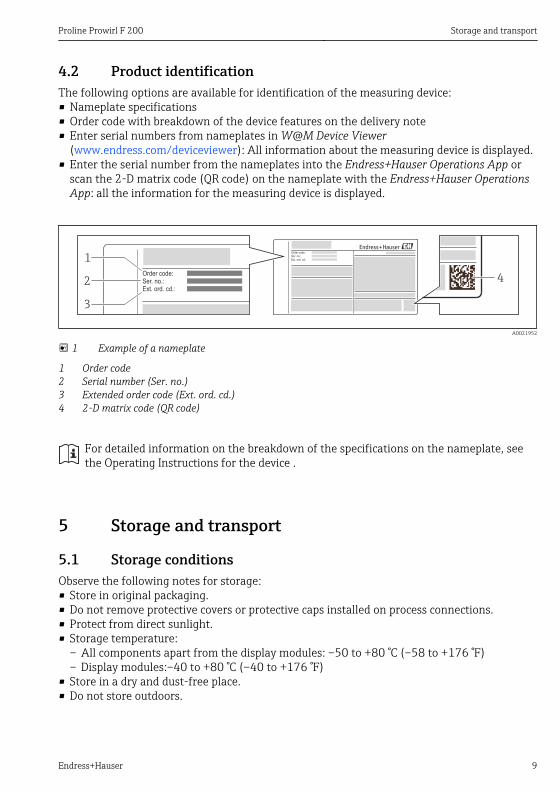
4.2 Product identificationThe following options are available for identification of the measuring device:• Nameplate specifications• Order code with breakdown of the device features on the delivery note• Enter serial numbers from nameplates in W@M Device Viewer
(www.endress.com/deviceviewer): All information about the measuring device is displayed.• Enter the serial number from the nameplates into the Endress+Hauser Operations App or
scan the 2-D matrix code (QR code) on the nameplate with the Endress+Hauser OperationsApp: all the information for the measuring device is displayed.
Order code:
Ext. ord. cd.:
Ser. no.:
Order code:
Ext. ord. cd.:
Ser. no.:
1
2
3
4
A0021952
1 Example of a nameplate
1 Order code2 Serial number (Ser. no.)3 Extended order code (Ext. ord. cd.)4 2-D matrix code (QR code)
For detailed information on the breakdown of the specifications on the nameplate, seethe Operating Instructions for the device .
5 Storage and transport
5.1 Storage conditionsObserve the following notes for storage:• Store in original packaging.• Do not remove protective covers or protective caps installed on process connections.• Protect from direct sunlight.• Storage temperature:
– All components apart from the display modules: –50 to +80 °C (–58 to +176 °F)– Display modules:–40 to +80 °C (–40 to +176 °F)
• Store in a dry and dust-free place.• Do not store outdoors.

Storage and transport Proline Prowirl F 200
10 Endress+Hauser
5.2 Transporting the productTransport the measuring device to the measuring point in the original packaging.
A0015604
Do not remove protective covers or caps installed on process connections. They preventmechanical damage to the sealing surfaces and contamination in the measuring tube.
5.2.1 Measuring devices without lifting lugs
LWARNINGCenter of gravity of the measuring device is higher than the suspension points of thewebbing slings.Risk of injury if the measuring device slips.‣ Secure the measuring device against slipping or turning.‣ Observe the weight specified on the packaging (stick-on label).
A0015606
5.2.2 Measuring devices with lifting lugs
LCAUTIONSpecial transportation instructions for devices with lifting lugs‣ Only use the lifting lugs fitted on the device or flanges to transport the device.‣ The device must always be secured at two lifting lugs at least.

Proline Prowirl F 200 Storage and transport
Endress+Hauser 11
5.2.3 Transporting with a fork liftIf transporting in wood crates, the floor structure enables the crates to be lifted lengthwise orat both sides using a forklift.

Installation Proline Prowirl F 200
12 Endress+Hauser
6 Installation
6.1 Installation conditions
6.1.1 Mounting position
Mounting location
A0015543
OrientationThe direction of the arrow on the sensor nameplate helps you to install the sensor accordingto the flow direction.Vortex meters require a fully developed flow profile as a prerequisite for correct volume flowmeasurement. Therefore, please note the following:
Orientation Compact version Remote version
A Vertical orientation
A0015545
1)
B Horizontal orientation, transmitter head up
A0015589
2) 3)
Proline Prowirl F 200 Installation
Endress+Hauser 13
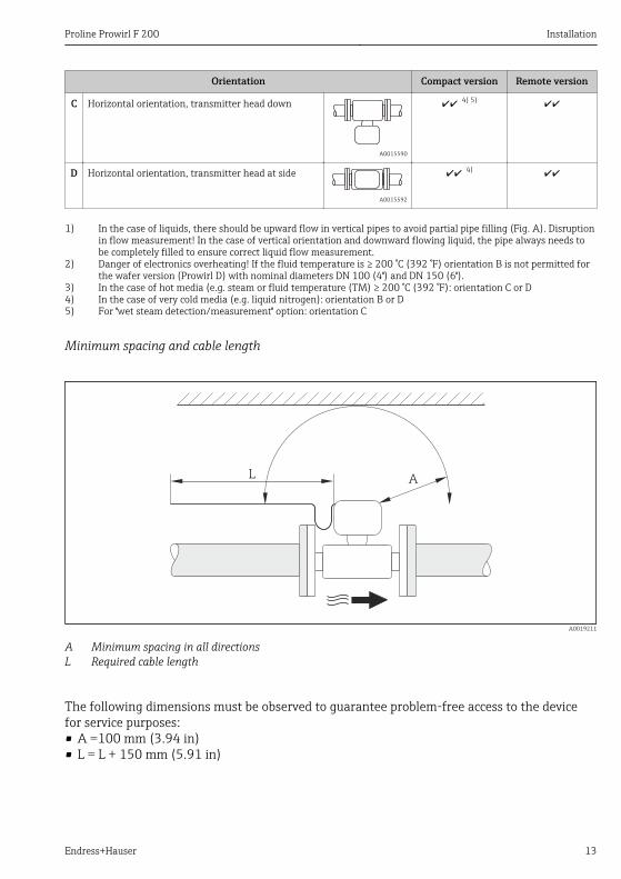
Orientation Compact version Remote version
C Horizontal orientation, transmitter head down
A0015590
4) 5)
D Horizontal orientation, transmitter head at side
A0015592
4)
1) In the case of liquids, there should be upward flow in vertical pipes to avoid partial pipe filling (Fig. A). Disruptionin flow measurement! In the case of vertical orientation and downward flowing liquid, the pipe always needs tobe completely filled to ensure correct liquid flow measurement.
2) Danger of electronics overheating! If the fluid temperature is ≥ 200 °C (392 °F) orientation B is not permitted forthe wafer version (Prowirl D) with nominal diameters DN 100 (4") and DN 150 (6").
3) In the case of hot media (e.g. steam or fluid temperature (TM) ≥ 200 °C (392 °F): orientation C or D4) In the case of very cold media (e.g. liquid nitrogen): orientation B or D5) For "wet steam detection/measurement" option: orientation C
Minimum spacing and cable length
AL
A0019211
A Minimum spacing in all directionsL Required cable length
The following dimensions must be observed to guarantee problem-free access to the devicefor service purposes:• A =100 mm (3.94 in)• L = L + 150 mm (5.91 in)

Installation Proline Prowirl F 200
14 Endress+Hauser
Rotating the electronics housing and the displayThe electronics housing can be rotated continuously by 360 °° on the housing support. Thedisplay unit can be rotated in 45 ° stages. This means you can read the display comfortablyfrom all directions.
Inlet and outlet runsTo attain the specified level of accuracy of the measuring device, the inlet and outlet runsmentioned below must be maintained at the very minimum.
15 × DN 5 × DN1 3
25 × DN 5 × DN
40 × DN 5 × DN4
2
20 × DN 5 × DN
520 × DN 5 × DN
617 × DN + 8 × h 5 × DNh
7
50 × DN 5 × DN
9
40 × DN 5 × DN
8
5 × DN
DN 25 (1"):≤ DN 40 (1½"):≥
A0019189
2 Minimum inlet and outlet runs with various flow obstructions
h Difference in expansion1 Reduction by one nominal diameter size2 Single elbow (90° elbow)3 Double elbow (2 × 90° elbows, opposite)4 Double elbow 3D (2 × 90° elbows, opposite, not on one plane)5 T-piece6 Expansion7 Control valve8 Two measuring devices in a row where DN ≤ 25 (1"): directly flange on flange9 Two measuring devices in a row where DN ≥ 40 (1½"): for spacing, see graphic

Proline Prowirl F 200 Installation
Endress+Hauser 15
• If there are several flow disturbances present, the longest specified inlet run must bemaintained.
• If the required inlet runs cannot be observed, it is possible to install a speciallydesigned flow conditioner (→ 19).
The inlet run correction function:• Makes it possible to shorten the inlet run to a minimum length of 10 × DN in the event
of flow obstructions 1-4. An additional measuring uncertainty of ±0.5% o.r. occurs .• Cannot be combined with the Wet Steam Detection/Measurement application
package. If wet steam detection/measurement is used, the corresponding inlet runsmust be taken into consideration. It is not possible to use a flow conditioner for wetsteam.
For detailed information about inlet run correction and wet steam detection, see theSpecial Documentation for the deviceFor the dimensions and installation lengths of the device, see the "Technical Information"document, "Mechanical construction" section
Flow conditionerIf the required inlet runs cannot be observed, it is possible to install a specially designed flowconditioner which can be ordered from Endress+Hauser. The flow conditioner is fittedbetween two pipe flanges and centered by the mounting bolts. Generally this reduces the inletrun needed to 10 × DN with full accuracy.
8 x DN2 x DN 5 x DN
1
A0019208
1 Flow conditioner
The pressure loss for flow conditioners is calculated as follows: ∆ p [mbar] = 0.0085 ⋅ ρ[kg/m3] ⋅ v2 [m/s]
Example for steam Example for H2O condensate (80 °C)
p = 10 bar abs. ρ = 965 kg/m3
t = 240 °C → ρ = 4.39 kg/m3 v =2.5 m/s
v =40 m/s ∆ p = 0.0085 ⋅ 965 ⋅ 2.5 2 = 51.3 mbar
∆ p = 0.0085 ⋅ 4.394.39 ⋅ 40 2 = 59.7 mbar

Installation Proline Prowirl F 200
16 Endress+Hauser
ρ : density of the process mediumv: average flow velocityabs. = absolute
Outlet runs when installing external devicesIf installing an external device, observe the specified distance.
PT TT
3...5 x DN
4...8 x DN
A0019205
PT Pressure transmitterTT Temperature transmitter
6.1.2 Requirements from environment and process
Ambient temperature range
Compact version
Measuring device Non-Ex: –40 to +80 °C (–40 to +176 °F) 1)
Ex i: –40 to +70 °C (–40 to +158 °F) 1)
EEx d/XP version: –40 to +60 °C (–40 to +140 °F) 1)
ATEX II1/2G Ex d, Ex ia: –40 to +60 °C (–40 to +140 °F) 1)
Local display –20 to +60 °C (–4 to +140 °F)
1) Additionally available as order code for "Test, certificate", option JN "Transmitter ambient temperature –50 °C (–58°F)".
Remote version
Transmitter Non-Ex: –40 to +80 °C (–40 to +176 °F) 1)
Ex i: –40 to +80 °C (–40 to +176 °F) 1)
Ex d: –40 to +60 °C (–40 to +140 °F) 1)
ATEX II1/2G Ex d, Ex ia: –40 to +60 °C (–40 to +140 °F) 1)

Proline Prowirl F 200 Installation
Endress+Hauser 17
Sensor Non-Ex: –40 to +85 °C (–40 to +185 °F) 1)
Ex i: –40 to +85 °C (–40 to +185 °F) 1)
Ex d: –40 to +85 °C (–40 to +185 °F) 1)
ATEX II1/2G Ex d, Ex ia: –40 to +85 °C (–40 to +185 °F) 1)
Local display –20 to +60 °C (–4 to +140 °F)
1) Additionally available as order code for "Test, certificate", option JN "Transmitter ambient temperature –50 °C (–58°F)".
‣ If operating outdoors:Avoid direct sunlight, particularly in warm climatic regions.
Temperature tablesObserve the interdependencies between the permitted ambient and fluid temperatureswhen operating the device in hazardous areas.For detailed information on the temperature tables, see the separate document entitled"Safety Instructions" (XA) for the device.
Thermal insulationFor optimum temperature measurement and mass calculation, heat transfer at the sensormust be avoided for some fluids. This can be ensured by installing thermal insulation. A widerange of materials can be used for the required insulation.This applies for:• Compact version• Remote sensor version
The maximum insulation height permitted is illustrated in the diagram:
1
A0019212
1 Maximum insulation height
‣ When insulating, ensure that a sufficiently large area of the housing support remainsexposed.
The uncovered part serves as a radiator and protects the electronics from overheating andexcessive cooling.

Installation Proline Prowirl F 200
18 Endress+Hauser
NOTICEElectronics overheating on account of thermal insulation!‣ Observe the maximum permitted insulation height of the transmitter neck so that the
transmitter head and/or the connection housing of the remote version is completely free.‣ Observe information on the permissible temperature ranges .‣ Note that a certain orientation might be required, depending on the fluid temperature
(→ 12).
For detailed information about the fluid temperature, orientations and permittedtemperature ranges, refer to the Operating Instructions for the device
VibrationsThe correct operation of the measuring system is not affected by plant vibrations up to 1 g,10 to 500 Hz. Therefore no special measures are needed to secure the sensors.

Proline Prowirl F 200 Installation
Endress+Hauser 19
6.1.3 Special mounting instructions
Installation for delta heat measurementsOrder code for "Sensor version", option 3 "Mass flow (integrated temperature measurement)"The second temperature measurement is taken using a separate temperature sensor. Themeasuring device reads in this value via a communication interface.• In the case of saturated steam delta heat measurements, the Prowirl 200 must be installed
on the steam side.• In the case of water delta heat measurements, the Prowirl 200 can be installed on the cold
or warm side.
Q
1
2
3
A0019209
3 Layout for delta heat measurement of saturated steam and water
1 Prowirl2 Temperature sensor3 Heat exchangerQ Heat flow
Weather protection coverObserve the following minimum head clearance: 222 mm (8.74 in)

Installation Proline Prowirl F 200
20 Endress+Hauser
6.2 Mounting the measuring device
6.2.1 Required tools
For transmitter• For turning the transmitter housing: Open-ended wrench8 mm• For opening the securing clamps: Allen key3 mm
For sensorFor flanges and other process connections: Corresponding mounting tools
6.2.2 Preparing the measuring device1. Remove all remaining transport packaging.2. Remove any protective covers or protective caps present from the sensor.3. Remove stick-on label on the electronics compartment cover.
6.2.3 Mounting the sensor
LWARNINGDanger due to improper process sealing!‣ Ensure that the inside diameters of the gaskets are greater than or equal to that of the
process connections and piping.‣ Ensure that the gaskets are clean and undamaged.‣ Install the gaskets correctly.
1. Ensure that the direction of the arrow on the sensor matches the flow direction of themedium.
2. To ensure compliance with device specifications, install the measuring device betweenthe pipe flanges in a way that it is centered in the measurement section.
3. Install the measuring device or turn the transmitter housing so that the cable entries donot point upwards.
A0013964

Proline Prowirl F 200 Installation
Endress+Hauser 21
6.2.4 Mounting the transmitter of the remote version
LCAUTIONAmbient temperature too high!Danger of electronics overheating and housing deformation.‣ Do not exceed the permitted maximum ambient temperature (→ 16).‣ If operating outdoors: Avoid direct sunlight and exposure to weathering, particularly in
warm climatic regions.
LCAUTIONExcessive force can damage the housing!‣ Avoid excessive mechanical stress.
Wall mounting
80 (3.15)
80
(3
.15
)
19 (0.6)
!8
.6 (
0.3
9)
M 8
A0019864
4 Engineering unit mm (in)

Installation Proline Prowirl F 200
22 Endress+Hauser
Post mounting
! 20…70
(! 0.79 to 2.75)
1
4 x SW 13
A0019862
5 Engineering unit mm (in)
1 Post retainer kit for post mounting
6.2.5 Turning the transmitter housingTo provide easier access to the connection compartment or display module, the transmitterhousing can be turned.
max. 350°
8 mm 8 mm
A0013713

Proline Prowirl F 200 Installation
Endress+Hauser 23
6.2.6 Turning the display moduleThe display module can be turned to optimize display readability and operability.
+
E
–
1
3 mm
A0013905
6.3 Post-installation check
Is the device undamaged (visual inspection)? Does the measuring device conform to the measuring point specifications?
For example:• Process temperature• Process pressure (refer to the section on "Pressure-temperature ratings" in the "Technical Information"
document )• Ambient temperature (→ 16)• Measuring range
Has the correct orientation for the sensor been selected (→ 12)?
• According to sensor type• According to medium temperature• According to medium properties (outgassing, with entrained solids)
Does the arrow on the sensor nameplate match the direction of flow of the fluid through the piping(→ 12)?
Are the measuring point identification and labeling correct (visual inspection)? Is the device adequately protected from precipitation and direct sunlight? Are the securing screw and securing clamp tightened securely?

Electrical connection Proline Prowirl F 200
24 Endress+Hauser
7 Electrical connectionThe measuring device does not have an internal circuit breaker. For this reason, assignthe measuring device a switch or power-circuit breaker so that the power supply line canbe easily disconnected from the mains.
7.1 Connection conditions
7.1.1 Required tools• For cable entries: Use corresponding tools• For securing clamp: Allen key 3 mm• Wire stripper• When using stranded cables: crimping tool for ferrule• For removing cables from terminal: flat blade screwdriver ≤3 mm (0.12 in)
7.1.2 Requirements for connecting cableThe connecting cables provided by the customer must fulfill the following requirements.
Electrical safetyIn accordance with applicable federal/national regulations.
Permitted temperature range• –40 °C (–40 °F) to +80 °C (+176 °F)• Minimum requirement: cable temperature range ≥ ambient temperature +20 K
Signal cable
Current outputFor 4-20 mA HART: Shielded cable recommended. Observe grounding concept of the plant.
Pulse/frequency/switch outputStandard installation cable is sufficient.
Current inputStandard installation cable is sufficient.
FOUNDATION FieldbusTwisted, shielded two-wire cable.
For further information on planning and installing FOUNDATION Fieldbus networks see:• Operating Instructions for "FOUNDATION Fieldbus Overview" (BA00013S)• FOUNDATION Fieldbus Guideline• IEC 61158-2 (MBP)
PROFIBUS PATwisted, shielded two-wire cable. Cable type A is recommended.

Proline Prowirl F 200 Electrical connection
Endress+Hauser 25
For further information on planning and installing PROFIBUS PA networks see:• Operating Instructions "PROFIBUS DP/PA: Guidelines for planning and commissioning"
(BA00034S)• PNO Directive 2.092 "PROFIBUS PA User and Installation Guideline"• IEC 61158-2 (MBP)
Connecting cable for remote version
Connecting cable (standard)
Standard cable 4 × 2 × 0.34 mm2 (22 AWG) PVC cable with common shield (4 pairs, pair-stranded)
Flame resistance According to DIN EN 60332-1-2
Oil-resistance According to DIN EN 60811-2-1
Shielding Galvanized copper-braid, opt. density approx. 85%
Cable length 5 m (16 ft), 10 m (32 ft), 20 m (65 ft), 30 m (98 ft)
Operating temperature When mounted in a fixed position: –50 to +105 °C (–58 to +221 °F); when cable canmove freely: –25 to +105 °C (–13 to +221 °F)
Connecting cable (reinforced)
Cable, reinforced 4 × 2 × 0.34 mm2 (22 AWG) PVC cable with common shield (4 pairs, pair-stranded)and additional steel-wire braided sheath
Flame resistance According to DIN EN 60332-1-2
Oil-resistance According to DIN EN 60811-2-1
Shielding Galvanized copper-braid, opt. density approx. 85%
Strain relief andreinforcement
Steel-wire braid, galvanized
Cable length 5 m (16 ft), 10 m (32 ft), 20 m (65 ft), 30 m (98 ft)
Operating temperature When mounted in a fixed position: –50 to +105 °C (–58 to +221 °F); when cable canmove freely: –25 to +105 °C (–13 to +221 °F)
Cable diameter• Cable glands supplied:
M20 × 1.5 with cable 6 to 12 mm (0.24 to 0.47 in)• Plug-in spring terminals for device version without integrated overvoltage protection: wire
cross-sections 0.5 to 2.5 mm2 (20 to 14 AWG)• Screw terminals for device version with integrated overvoltage protection: wire cross-
sections 0.2 to 2.5 mm2 (24 to 14 AWG)

Electrical connection Proline Prowirl F 200
26 Endress+Hauser
7.1.3 Terminal assignment
Transmitter
Connection versions
–
4
+
1
–
2
+
3
12 4
–
6
+
5
3
A0020738
+
1
–
2
–
4
+
3
–
6
+
5
3 12 4
A0020739
Maximum number of terminalsTerminals 1 to 6:Without integrated overvoltage protection
Maximum number of terminals for order code for"Accessory mounted", option NA "Overvoltageprotection"• Terminals 1 to 4:
With integrated overvoltage protection• Terminals 5 to 6:
Without integrated overvoltage protection
1234
Output 1 (passive): supply voltage and signal transmissionOutput 2 (passive): supply voltage and signal transmissionInput (passive): supply voltage and signal transmissionGround terminal for cable shield
Order code for "Output" Terminal numbers
Output 1 Output 2 Input
1 (+) 2 (-) 3 (+) 4 (-) 5 (+) 6 (-)
Option A 4-20 mA HART (passive) - -
Option B 1) 4-20 mA HART (passive) Pulse/frequency/switchoutput (passive) -
Option C 1) 4-20 mA HART (passive) 4-20 mA (passive) -
Option D 1) 2) 4-20 mA HART (passive) Pulse/frequency/switchoutput (passive)
4-20 mA current input(passive)
Option E 1) 3) FOUNDATION Fieldbus Pulse/frequency/switchoutput (passive) -
Option G 1) 4) PROFIBUS PA Pulse/frequency/switchoutput (passive) -
1) Output 1 must always be used; output 2 is optional.2) The integrated overvoltage protection is not used with option D: Terminals 5 and 6 (current input) are not
protected against overvoltage.3) FOUNDATION Fieldbus with integrated reverse polarity protection.4) PROFIBUS PA with integrated reverse polarity protection.

Proline Prowirl F 200 Electrical connection
Endress+Hauser 27
Remote versionIn the case of the remote version, the sensor and transmitter are mounted separately fromone another and connected by a connecting cable. The sensor is connected via the connectionhousing while the transmitter is connected via the connection compartment of the wall holderunit.
The way the transmitter wall holder is connected depends on the measuring deviceapproval and the version of the connecting cable used.Connection is only possible via terminals:• For approvals Ex n, Ex tb and cCSAus Div. 1• If a reinforced connecting cable is usedThe connection is via an M12 connector:• For all other approvals• If the standard connecting cable is usedConnection to the connection housing of the sensor is always via terminals.
41 2 3
1
2
+ –
A0019335
6 Terminals for connection compartment in the transmitter wall holder and the sensor connectionhousing
1 Terminals for connecting cable2 Grounding via the cable strain relief
Terminal number Assignment Cable colorConnecting cable
1 Supply voltage Brown
2 Grounding White
3 RS485 (+) Yellow
4 RS485 (–) Green

Electrical connection Proline Prowirl F 200
28 Endress+Hauser
7.1.4 Pin assignment, device plug
PROFIBUS PA
Device plug for signal transmission (device side)
1
2
4
3
A0019021
Pin Assignment Coding Plug/socket1 + PROFIBUS PA + A Plug2 Grounding3 - PROFIBUS PA –4 Not assigned
FOUNDATION Fieldbus
Device plug for signal transmission (device side)
1
2
4
3
A0019021
Pin Assignment Coding Plug/socket1 + Signal + A Plug2 - Signal –3 Not assigned4 Grounding
7.1.5 Shielding and groundingOptimum electromagnetic compatibility (EMC) of the fieldbus system can only be guaranteedif the system components and, in particular, the lines are shielded and the shield forms ascomplete a cover as possible. A shield coverage of 90% is ideal.• To ensure an optimum EMC protective effect, connect the shield as often as possible to the
reference ground.• For reasons of explosion protection, you should refrain from grounding however.To comply with both requirements, the fieldbus system allows three different types ofshielding:• Shielding at both ends.• Shielding at one end on the feed side with capacitance termination at the field device.• Shielding at one end on the feed side.Experience shows that the best results with regard to EMC are achieved in most cases ininstallations with one-sided shielding on the feed side (without capacitance termination atthe field device). Appropriate measures with regard to input wiring must be taken to allowunrestricted operation when EMC interference is present. These measures have been takeninto account for this device. Operation in the event of disturbance variables as per NAMURNE21 is thus guaranteed.Where applicable, national installation regulations and guidelines must be observed duringthe installation!Where there are large differences in potential between the individual grounding points, onlyone point of the shielding is connected directly with the reference ground. In systems without

Proline Prowirl F 200 Electrical connection
Endress+Hauser 29
potential equalization, therefore, cable shielding of fieldbus systems should only be groundedon one side, for example at the fieldbus supply unit or at safety barriers.
21 3
+-
+-
+-
4
5
5
78
6 6
6
6
6
6
. -
A0019004
1 Controller (e.g. PLC)2 Segment coupler PROFIBUS DP/PA or Power Conditioner (FOUNDATION Fieldbus)3 Cable shield4 T-box5 Measuring device6 Local grounding7 Bus terminator8 Potential matching line
NOTICEIn systems without potential matching, the multiple grounding of the cable shield causesmains frequency equalizing currents!Damage to the bus cable shield.‣ Only ground the bus cable shield to either the local ground or the protective ground at one
end. Insulate the shield that is not connected.

Electrical connection Proline Prowirl F 200
30 Endress+Hauser
7.1.6 Requirements for the supply unit
Supply voltage
Transmitter
Increase in minimum terminal voltage
Local operation Increase in minimumterminal voltage
Order code for "Display; Operation", option C:Local operation SD02 + DC 1 V
Order code for "Display; Operation", option E:Local operation SD03 with lighting(backlighting not used)
+ DC 1 V
Order code for "Display; Operation", option E:Local operation SD03 with lighting(backlighting used)
+ DC 3 V
LoadLoad for current output: 0 to 500 Ω, depending on the external supply voltage of the powersupply unit
Calculation of the maximum loadDepending on the supply voltage of the power supply unit (US), the maximum load (RB)including line resistance must be observed to ensure adequate terminal voltage at the device.In doing so, observe the minimum terminal voltage (→ 30)• RB ≤ (US - Uterm. min) :0.022 A• RB ≤500 Ω

Proline Prowirl F 200 Electrical connection
Endress+Hauser 31
0
100
200
300
400
500
12 14 16 18 20 22 24 26 28 U [V]s
R [ ]b W 1.1 1.21
30 32 34 3635
A0020417
7 Load for a compact version without local operation
1 Operating range1.1 For order code for "Output", option A "4-20 mA HART"/option B "4-20 mA HART, pulse/frequency/
switch output" with Ex i and option C "4-20 mA HART, 4-20 mA"1.2 For order code for "Output", option A "4-20 mA HART"/option B "4-20 mA HART, pulse/frequency/
switch output" with non-Ex and Ex d
Sample calculationSupply voltage of the supply unit:– US = 19 V– Uterm. min = 12 V (measuring device) + 1 V (local operation without lighting) = 13 VMaximum load: RB≤ (19 V - 13 V) :0.022 A = 273 Ω
The minimum terminal voltage (Uterm. min) increases if local operation is used (→ 30).
7.1.7 Preparing the measuring device1. Remove dummy plug if present.2. NOTICE! Insufficient sealing of the housing! Operational reliability of the measuring
device could be compromised. Use suitable cable glands corresponding to the degree ofprotection.If measuring device is delivered without cable glands:Provide suitable cable gland for corresponding connecting cable (→ 24).
3. If measuring device is delivered with cable glands:Observe cable specification (→ 24).

Electrical connection Proline Prowirl F 200
32 Endress+Hauser
7.2 Connecting the measuring deviceNOTICE
Limitation of electrical safety due to incorrect connection!‣ For use in potentially explosive atmospheres, observe the information in the device-specific
Ex documentation.
7.2.1 Connecting the remote version
LWARNINGRisk of damaging the electronic components!‣ Ground the remote version and in doing so connect the sensor and transmitter to the same
potential equalization.‣ Only connect the sensor to a transmitter with the same serial number.
The following procedure (in the action sequence given) is recommended for the remoteversion:
1. Mount the transmitter and sensor.2. Connect the connecting cable.3. Connect the transmitter.
The way the transmitter wall holder is connected depends on the measuring deviceapproval and the version of the connecting cable used.Connection is only possible via terminals:• For approvals Ex n, Ex tb and cCSAus Div. 1• If a reinforced connecting cable is usedThe connection is via an M12 connector:• For all other approvals• If the standard connecting cable is usedConnection to the connection housing of the sensor is always via terminals.

Proline Prowirl F 200 Electrical connection
Endress+Hauser 33
Connecting the sensor connection housing
3 mm
A0020410
A0020411
1. Wire the connecting cable:Terminal 1 = brown cableTerminal 2 = white cableTerminal 3 = yellow cableTerminal 4 = green cable
2. Connect the cable shield via the cable strain relief.
Electrical connection Proline Prowirl F 200
34 Endress+Hauser
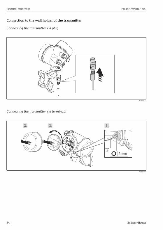
Connection to the wall holder of the transmitter
Connecting the transmitter via plug
A0020412
Connecting the transmitter via terminals
+
E
–
3 mm
A0020404

Proline Prowirl F 200 Electrical connection
Endress+Hauser 35
8 mm
TX 10
A0020405
~15°
A0020406

Electrical connection Proline Prowirl F 200
36 Endress+Hauser
A0020407
A0020409
1. Wire the connecting cable:Terminal 1 = brown cableTerminal 2 = white cableTerminal 3 = yellow cableTerminal 4 = green cable
2. Connect the cable shield via the cable strain relief.
7.2.2 Connecting the transmitterThe connection of the transmitter depends on the following order codes:Connection version: terminals or device plug

Proline Prowirl F 200 Electrical connection
Endress+Hauser 37
Connection via terminals
10 (0.4)
mm (in)
20mm3 mm
A0013836
‣ Connect the cable in accordance with the terminal assignment . For HARTcommunication: when connecting the cable shielding to the ground terminal, observethe grounding concept of the facility.
Connection via device plug
A0019147
‣ Plug in the device plug and tighten firmly.

Electrical connection Proline Prowirl F 200
38 Endress+Hauser
7.3 Hardware settings
7.3.1 Setting the device address
PROFIBUS PAThe address must always be configured for a PROFIBUS DP/PA device. The valid addressrange is between 1 and 126. In a PROFIBUS DP/PA network, each address can only beassigned once. If an address is not configured correctly, the device is not recognized by themaster. All measuring devices are delivered from the factory with the device address 126 andwith the software addressing method.
2
98
34
56
78
1
DIP
ON
A0015686
8 Address switch in the connection compartment
Hardware addressing1. Set switch 8 to the "OFF" position.2. Using switches 1 to 7, set the address as indicated in the table below.
The change of address takes effect after 10 seconds. The device is restarted.
Switch 1 2 3 4 5 6 7
Value in "ON" position 1 2 4 8 16 32 64
Value in "OFF" position 0 0 0 0 0 0 0

Proline Prowirl F 200 Electrical connection
Endress+Hauser 39
2
98
3 4 5 6 7 81
DIPON
2 + 8 = 10
A0015902
9 Example of hardware addressing; switch 8 is set to the "OFF" position; switches 1 to 7 define theaddress.
Software addressing1. Set switch 8 to "ON".
The device restarts automatically and reports the current address (factory setting:126).
2. Configuring the address via the operating menu: Setup menu→Communicationsubmenu→Device address parameter
2
98
3 4 5 6 7 81
DIPON
A0015903
10 Example of software addressing; switch 8 is set to the "ON" position; the address is defined in theoperating menu ("Setup" menu→"Communication" submenu→"Device address" parameter).
7.4 Ensuring the degree of protectionThe measuring device fulfills all the requirements for the IP66/67 degree of protection, Type4X enclosure.
To guarantee IP66/67 degree of protection, Type 4X enclosure, carry out the following stepsafter the electrical connection:
1. Check that the housing seals are clean and fitted correctly. Dry, clean or replace theseals if necessary.
2. Tighten all housing screws and screw covers.3. Firmly tighten the cable glands.4. To ensure that moisture does not enter the cable entry, route the cable so that it loops
down before the cable entry ("water trap").

Electrical connection Proline Prowirl F 200
40 Endress+Hauser
A0013960
5. Insert dummy plugs into unused cable entries.
7.5 Post-connection check
Are cables or the device undamaged (visual inspection)? Do the cables comply with the requirements (→ 24)? Do the cables have adequate strain relief? Are all the cable glands installed, firmly tightened and leak-tight? Cable run with "water trap"(→ 39) ?
Depending on the device version: are all the device plugs firmly tightened ? Does the supply voltage match the specifications on the transmitter nameplate (→ 30)? Is the terminal assignment correct ? Is the terminal assignment or the pin assignment of the device plug correct? If supply voltage is present, do values appear on the display module? Are all housing covers installed and firmly tightened? Is the securing clamp tightened correctly?

Proline Prowirl F 200 Operation options
Endress+Hauser 41
8 Operation options
8.1 Structure and function of the operating menu
8.1.1 Structure of the operating menu
!
Expert
Operating menu for experts
Language
Operation
Setup
Diagnostics
Operating menu for operators and maintenancesO
pe
rato
r
Ma
inte
na
nce
task-oriented
function-oriented
Ex
pe
rt
A0014058-EN
11 Schematic structure of the operating menu
8.1.2 Operating philosophyThe individual parts of the operating menu are assigned to certain user roles (operator,maintenance etc.). Each user role contains typical tasks within the device lifecycle.
For detailed information on the operating philosophy, see the Operating Instructions forthe device.

Operation options Proline Prowirl F 200
42 Endress+Hauser
8.2 Access to the operating menu via the local display
5
4ABC_ DEFG
UserHIJK
LMNO PQRS TUVW
XYZ Aa1
2.1
2.2
2.4
2.5
2.3
2.6
2 X X X X X XX
l/s
19.184 mA
12.5
3.1
3.2
Ã
Español
Français
Language
EnglishDeutsch
31.1
1.3
1.5
1.6ESC
E
X X X X X XX
20.50S
mA
1.4
1.7
1.2
1
3 40 1 295 6 87
30
A0014013
1 Operational display with measured value shown as "1 value, max." (example)1.1 Device tag1.2 Display area for measured values (4-line)1.3 Explanatory symbols for measured value: Measured value type, measuring channel number, symbol
for diagnostic behavior1.4 Status area1.5 Measured value1.6 Unit for the measured value1.7 Operating elements2 Operational display with measured value shown as "1 bar graph + 1 value" (example)2.1 Bar graph display for measured value 12.2 Measured value 1 with unit2.3 Explanatory symbols for measured value 1: measured value type, measuring channel number2.4 Measured value 22.5 Unit for measured value 22.6 Explanatory symbols for measured value 2: measured value type, measuring channel number3 Navigation view: picklist of a parameter3.1 Navigation path and status area3.2 Display area for navigation: designates the current parameter value4 Editing view: text editor with input mask5 Editing view: numeric editor with input mask
Proline Prowirl F 200 Operation options
Endress+Hauser 43
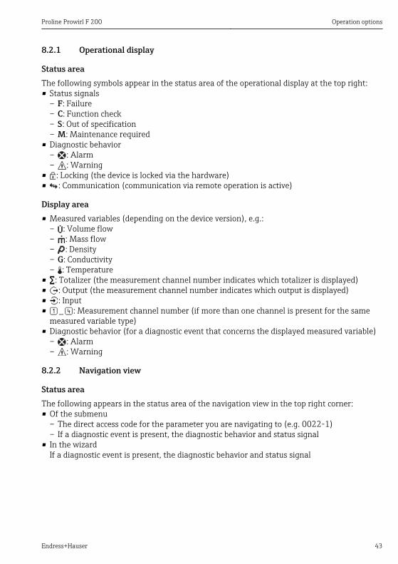
8.2.1 Operational display
Status areaThe following symbols appear in the status area of the operational display at the top right:• Status signals
– F: Failure– C: Function check– S: Out of specification– M: Maintenance required
• Diagnostic behavior– : Alarm– : Warning
• : Locking (the device is locked via the hardware)• : Communication (communication via remote operation is active)
Display area• Measured variables (depending on the device version), e.g.:
– : Volume flow– : Mass flow– : Density– G: Conductivity– : Temperature
• : Totalizer (the measurement channel number indicates which totalizer is displayed)• : Output (the measurement channel number indicates which output is displayed)• : Input• : Measurement channel number (if more than one channel is present for the same
measured variable type)• Diagnostic behavior (for a diagnostic event that concerns the displayed measured variable)
– : Alarm– : Warning
8.2.2 Navigation view
Status areaThe following appears in the status area of the navigation view in the top right corner:• Of the submenu
– The direct access code for the parameter you are navigating to (e.g. 0022-1)– If a diagnostic event is present, the diagnostic behavior and status signal
• In the wizardIf a diagnostic event is present, the diagnostic behavior and status signal

Operation options Proline Prowirl F 200
44 Endress+Hauser
Display area• Icons for menus
– : Operation– : Setup– : Diagnostics– : Expert
• : Submenus• : Wizards• : Parameters within a wizard• : Parameter locked
8.2.3 Editing view
Input mask
Operating symbols in the numeric editor
Key Meaning Key Meaning
Confirms selection. Moves the input position one positionto the left.
Exits the input without applying thechanges. .
Inserts decimal separator at the inputposition.
–
Inserts minus sign at the inputposition.
Clears all entered characters.
Operating symbols in the text editor
Key Meaning Key Meaning
Confirms selection. Switches to the selection of thecorrection tools.
Exits the input without applying thechanges.
Clears all entered characters.
Aa1
Toggle• Between upper-case and lower-case letters• For entering numbers• For entering special characters
Correction symbols under
Key Meaning Key Meaning
Clears all entered characters. Moves the input position one positionto the left.
Moves the input position one positionto the right.
Deletes one character immediately tothe left of the input position.

Proline Prowirl F 200 Operation options
Endress+Hauser 45
8.2.4 Operating elements
Keys and meaning
Minus key
• In a menu, submenu: Moves the selection bar upwards in a choose list.• With a wizard: Confirms the parameter value and goes to the previous parameter.• With a text and numeric editor: Moves the selection bar to the left (backwards) in an input screen.
Plus key
• In a menu, submenu: Moves the selection bar downwards in a choose list.• With a wizard: Confirms the parameter value and goes to the next parameter.• With a text and numeric editor: Moves the selection bar to the right (forwards) in an input screen.
Enter key
For operational display• Pressing the key briefly opens the operating menu.• Pressing the key for 2 s opens the context menu.
In a menu, submenu• Pressing the key briefly:
– Opens the selected menu, submenu or parameter.– Starts the wizard.– If help text is open, closes the help text of the parameter.
• Pressing the key for 2 s for parameter: If present, opens the help text for the function of the parameter.
With a wizard: Opens the editing view of the parameter.
With a text and numeric editor:• Pressing the key briefly:
– Opens the selected group.– Carries out the selected action.
• Pressing the key for 2 s confirms the edited parameter value.
+ Escape key combination (press keys simultaneously)
In a menu, submenu• Pressing the key briefly:
– Exits the current menu level and takes you to the next higher level.– If help text is open, closes the help text of the parameter.
• Pressing the key for 2 s for the parameter: Returns you to the operational display ("home position").
With a wizard: Exits the wizard and takes you to the next higher level.With a text and numeric editor: Closes the text or numeric editor without applying changes.
+ Minus/Enter key combination (press the keys simultaneously)
Reduces the contrast (brighter setting).
+ Plus/Enter key combination (press and hold down the keys simultaneously)
Increases the contrast (darker setting).
+ + Minus/Plus/Enter key combination (press the keys simultaneously)
For operational display: Enables or disables the keypad lock (only SD02 display module).

System integration Proline Prowirl F 200
46 Endress+Hauser
8.2.5 Further informationFor further information on the following topics, see the Operating Instructions for thedevice• Calling up help text• User roles and related access authorization• Disabling write protection via access code• Enabling and disabling the keypad lock
8.3 Access to the operating menu via the operating toolFor detailed information about access to the operating menu via operating tool, refer tothe Operating Instructions for the device .
9 System integrationFor detailed information on system integration, see the Operating Instructions for thedevice.
9.1 Cyclic data transmission Cyclic data transmission when using the device master file (GSD).
9.1.1 Block modelThe block model shows which input and output data the measuring device makes available forcyclic data exchange. Cyclic data exchange takes place with a PROFIBUS master (Class 1), e.g.a control system etc.
Measuring device Control system
TransducerBlock
Analog Input block 1 to 4 (→ 47) Output value AI →
PROFIBUS DP
Totalizer block 1 to 3 (→ 48)
Output value TOTAL →
Controller SETTOT ←
Configuration MODETOT ←
Analog Output block 1 (→ 49) Input values AO ←
Discrete Input block 1 to 2 (→ 49) Output values DI →
Discrete Output block 1 to 3 (→ 50) Input values DO ←
Proline Prowirl F 200 System integration
Endress+Hauser 47
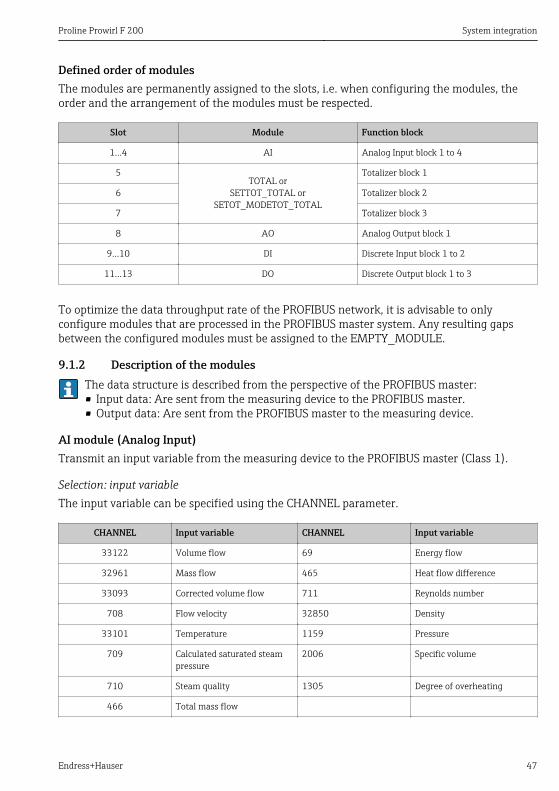
Defined order of modulesThe modules are permanently assigned to the slots, i.e. when configuring the modules, theorder and the arrangement of the modules must be respected.
Slot Module Function block
1…4 AI Analog Input block 1 to 4
5TOTAL or
SETTOT_TOTAL orSETOT_MODETOT_TOTAL
Totalizer block 1
6 Totalizer block 2
7 Totalizer block 3
8 AO Analog Output block 1
9…10 DI Discrete Input block 1 to 2
11…13 DO Discrete Output block 1 to 3
To optimize the data throughput rate of the PROFIBUS network, it is advisable to onlyconfigure modules that are processed in the PROFIBUS master system. Any resulting gapsbetween the configured modules must be assigned to the EMPTY_MODULE.
9.1.2 Description of the modulesThe data structure is described from the perspective of the PROFIBUS master:• Input data: Are sent from the measuring device to the PROFIBUS master.• Output data: Are sent from the PROFIBUS master to the measuring device.
AI module (Analog Input)Transmit an input variable from the measuring device to the PROFIBUS master (Class 1).
Selection: input variableThe input variable can be specified using the CHANNEL parameter.
CHANNEL Input variable CHANNEL Input variable
33122 Volume flow 69 Energy flow
32961 Mass flow 465 Heat flow difference
33093 Corrected volume flow 711 Reynolds number
708 Flow velocity 32850 Density
33101 Temperature 1159 Pressure
709 Calculated saturated steampressure
2006 Specific volume
710 Steam quality 1305 Degree of overheating
466 Total mass flow

System integration Proline Prowirl F 200
48 Endress+Hauser
Factory setting
Function block Factory setting Function block Factory setting
AI 1 Volume flow AI 3 Corrected volumeflow
AI 2 Mass flow AI 4 Density
TOTAL moduleTransmit a totalizer value from the measuring device to the PROFIBUS master (Class 1).
Selection: totalizer valueThe totalizer value can be specified using the CHANNEL parameter.
CHANNEL Input variable CHANNEL Input variable
33122 Volume flow 467 Condensate mass flow
32961 Mass flow 69 Energy flow
33093 Corrected volume flow 465 Heat flow difference
466 Total mass flow
Factory setting
Function block Factory setting: TOTAL
Totalizer 1, 2 and 3 Volume flow
SETTOT_TOTAL moduleThe module combination consists of the SETTOT and TOTAL functions:• SETTOT: Control the totalizers via the PROFIBUS master.• TOTAL: Transmit the totalizer value along with the status to the PROFIBUS master.
Selection: control totalizer
CHANNEL Value SETTOT Control totalizer
33310 0 Totalize
33046 1 Resetting
33308 2 Adopt totalizer initial setting
Factory setting
Function block Factory setting: Value SETTOT (meaning)
Totalizer 1, 2 and 3 0 (totalizing)

Proline Prowirl F 200 System integration
Endress+Hauser 49
SETTOT_MODETOT_TOTAL moduleThe module combination consists of the SETTOT, MODETOT and TOTAL functions:• SETTOT: Control the totalizers via the PROFIBUS master.• MODETOT: Configure the totalizers via the PROFIBUS master.• TOTAL: Transmit the totalizer value along with the status to the PROFIBUS master.
Selection: totalizer configuration
CHANNEL MODETOT value Totalizer configuration
33306 0 Balancing
33028 1 Balance the positive flow
32976 2 Balance the negative flow
32928 3 Stop totalizing
Factory setting
Function block Factory setting: Value MODETOT (meaning)
Totalizer 1, 2 and 3 0 (balancing)
AO module (Analog Output)Transmit a compensation value from the PROFIBUS master (Class 1) to the measuring device.
Assigned compensation valuesA compensation value is permanently assigned to the individual Analog Output blocks.
CHANNEL Function block Compensation value
1507 AO 1 External compensation
The selection is made via: "Expert" menu → Sensor → External comp.
DI module (Discrete Input)Transmit discrete input values from the measuring device to the PROFIBUS master (Class 1).

Commissioning Proline Prowirl F 200
50 Endress+Hauser
Selection: device functionThe device function can be specified using the CHANNEL parameter.
CHANNEL Device function Factory setting: state (meaning)
893 Switch output state• 0 (device function not active)• 1 (device function active)895 Low flow cut off
1430 Status verification 1)
1) Only available with the "Heartbeat Verification" application package
Factory setting
Function block Factory setting Function block Factory setting
DI 1 Switch output state DI 2 Low flow cut off
DO module (Discrete Output)Transmit discrete output values from the PROFIBUS master (Class 1) to the measuring device.
Assigned device functionsA device function is permanently assigned to the individual Discrete Output blocks.
CHANNEL Function block Device function Values: control (meaning)
891 DO 1 Flow override • 0 (disable device function)• 1 (enable device function)1429 DO 2 Start verification 1)
1) Only available with the "Heartbeat Verification" application package
EMPTY_MODULE moduleThis module is used to assign empty spaces arising from modules not being used in the slots(→ 47).
10 Commissioning
10.1 Function checkBefore commissioning the device, make sure that the post-installation and post-connectionchecks have been performed.• "Post-installation check" checklist (→ 23)• "Post-connection check" checklist (→ 40)

Proline Prowirl F 200 Commissioning
Endress+Hauser 51
10.2 Switching on the measuring deviceAfter a successful function check, switch on the measuring device.After a successful startup, the local display switches automatically from the startup display tothe operational display.
If nothing appears on the local display or a diagnostic message is displayed, refer to theOperating Instructions for the device
10.3 Setting the operating languageFactory setting: English or ordered local language
X X X X X X XX X
20.50
Operation
Setup
Main menu 0104-1
LanguageEnglish
Español
Français
Language
EnglishDeutsch
Ã
0104-1
Ã
Español
Français
Language
EnglishDeutsch
0104-1
Betrieb
Setup
Hauptmenü
SpracheDeutsch
0104-1
XXXX
A0013996
12 Using the example of the local display
10.4 Configuring the measuring deviceThe Setup menu and its guided wizards enable fast commissioning of the measuring device.The wizards systematically guide the user through all the parameters required forconfiguration, such as parameters for measurement or outputs.

Diagnostic information Proline Prowirl F 200
52 Endress+Hauser
The wizards available in the particular device can vary on account of the device version(e.g. communication method).
Wizard Meaning
Current output 1 Set output 1
Current output 2 Set output 2
Pulse/frequency/switch output Configure the analog inputs
Analog inputs Configure the selected output type
Display Configure the measured value display
Output conditioning Define the output conditioning
Low flow cut off Set the low flow cut off
10.5 Protecting settings from unauthorized accessThe following options exist for protecting the configuration of the measuring device fromunintentional modification after commissioning:• Write protection via access code• Write protection via write protection switch• Write protection via keypad lock• Write protection via block operation
For detailed information on protecting the settings against unauthorized access, see theOperating Instructions for the device.
11 Diagnostic informationFaults detected by the self-monitoring system of the measuring device are displayed as adiagnostic message in alternation with the operational display. The message on remedialmeasures can be called up from the diagnostic messages, and contains important informationon the fault.

Proline Prowirl F 200 Diagnostic information
Endress+Hauser 53
X X X X X X XX X X X X X X X XX XS S
XX
20.50X i
S801
Menu
S
(ID:203)
S801 0d00h02m25s
1
2
4
6
3
5
Increase supply voltage
S801 Supply voltage
Diagnostic list
Diagnostics 1
Diagnostics 2Diagnostics 3
Supply voltage
Supply voltage
A0013940-EN
13 Message for remedial measures
1 Diagnostic information2 Short text3 Service ID4 Diagnostic behavior with diagnostic code5 Operation time of occurrence6 Remedial measures
The user is in the diagnostic message.1. Press ( symbol).
The Diagnostic list submenu opens.2. Select the desired diagnostic event with or and press .
The message for the remedial measures for the selected diagnostic event opens.3. Press + simultaneously.
The message for the remedial measures closes.


www.addresses.endress.com