Impacts of Ice-Shelf Melting on Water-Mass Transformation ...

Projectile Mass Distribution Following Impacts on Hardened Steel Plate
A dissertation submitted by
John Stephens
In fulfillment of the requirements of
ENG4112 Research Project
Towards the degree of
Bachelor of Engineering (Mechanical)
Submitted 13th of October 2016
John Stephens 0061049689 12/10/15
2
Table of Contents Abstract ..................................................................................................................................................... 4
Disclaimer.................................................................................................................................................. 5
Certification............................................................................................................................................... 6
Acknowledgements ................................................................................................................................... 7
List of Figures ............................................................................................................................................ 8
List of Tables ............................................................................................................................................. 8
List of Appendices ..................................................................................................................................... 8
Chapter 1 - Introduction ........................................................................................................................... 9
Background ........................................................................................................................................... 9
Project Aim .......................................................................................................................................... 10
Objectives............................................................................................................................................ 10
Expected outcomes ............................................................................................................................. 10
Chapter 2 - Preliminary Research ........................................................................................................... 11
Justification of Research ..................................................................................................................... 11
Available Research Documentation .................................................................................................... 12
Projectile Materials ............................................................................................................................. 13
Target Materials ................................................................................................................................. 13
Cartridge Selection .............................................................................................................................. 14
Chapter 3 - Safety and Risk ..................................................................................................................... 15
General Risk Management .................................................................................................................. 15
Commercial Risk Management ........................................................................................................... 15
Project Planning .................................................................................................................................. 16
Resource Requirements ...................................................................................................................... 16
Chapter 4 - Methodology ........................................................................................................................ 17
Numerical Simulation .......................................................................................................................... 18
Field Testing ........................................................................................................................................ 20
Chapter 5 - Results .................................................................................................................................. 22
Field Testing ........................................................................................................................................ 22
ANSYS Simulation ................................................................................................................................ 26

John Stephens 0061049689 12/10/15
3 Chapter 6 - Conclusions and Recommendations .................................................................................... 30
Bibliography ............................................................................................................................................ 32
Appendix A - Project Specification .......................................................................................................... 34
Appendix B - Risk Management Plan ...................................................................................................... 35
Appendix C - Testing Equipment and Consumables ............................................................................... 37
Appendix D- Field Testing Data compiled in Solidworks ......................................................................... 38
John Stephens 0061049689 12/10/15
4 Abstract
Hardened steel plate is a commonly used material for reusable targets in shooting clubs, particularly
pistol clubs. The use of this plate creates safety concerns as the bullets are destroyed on impact and the
bullet mass is deflected in sometimes unpredictable directions. Eye protection is mandatory in situations
where steel targets will be shot at close range, however the relationship between shooting club
organisers and the Police Weapons Licensing branch can often be strained in disagreements as to
whether steel targets are being used appropriately.
The aim of this research project has been to gain a greater understanding of the behavior of lead
projectiles after impact with steel plates, particularly the way in which the projectile fragments are
distributed upon impact and the relationship between that distribution and the impact angle of the
projectile against the target surface. This research will be beneficial to the relevant shooting sports
where steel targets are used. It will assist competition organisers in setting targets and knowing what
extra measures may be required for the safety of shooters.
The preliminary research of this report led to the selection of Bisplate 500 as the experimental target
material, due to its common use as a target material and its availability. The rifle selected for the
experiment was chambered in 32-20 Winchester. The legal limitations on where pistols are permitted to
be used led to the decision to use a rifle instead as it allowed the testing to be undertaken on private
property. The 32-20 cartridge fires a 115 grain (7.45 gram) lead-tin alloy projectile, very similar to the
9mm and .38 super projectiles most commonly used in pistol target shooting.
The experimental component of this research project involved both computer simulation and field
testing of projectile impacts on hardened steel plate. The field testing revealed that the projectile
fragments are deflected away from the impact site on the plane made by the face of the target. As the
impact angle is reduced the fragments are still deflected on the same plane, however eventually the
distribution of the fragments becomes biased to the lower side of the target. The critical angle at which
there are no longer fragments deflected in all directions is 27.5°. At 24° the fragments are completely
deflected below the impact point.
The ANSYS simulations produced results that reinforced the findings of the field testing at impact angles
between 90° and 65°. At 65° the ANSYS simulations began to show the fragment distribution become
biased toward the lower side of the target and see the beginning of a section at the top of the fragment
pattern where there was no evidence of fragments, something not seen in the field testing until 27.5°.
The recommendations at the conclusion of this research project are that the safest way to setup steel
targets on a range is to ensure that the plates are as close to perpendicular to the shooting positions as
possible. It was identified that because the fragments are predominantly contained within a narrow
plane of travel, they would be easily contained within a loop of absorbent material such as rubber
conveyor belting.

John Stephens 0061049689 12/10/15
5
Disclaimer
University of Southern Queensland
Faculty of Health, Engineering and Sciences
ENG4111/ENG4112 Research Project
Limitations of Use
The Council of the University of Southern Queensland, its Faculty of Health, Engineering & Sciences, and
the staff of the University of Southern Queensland, do not accept any responsibility for the truth,
accuracy or completeness of material contained within or associated with this dissertation.
Persons using all or any part of this material do so at their own risk, and not at the risk of the Council of
the University of Southern Queensland, its Faculty of Health, Engineering & Sciences or the staff of the
University of Southern Queensland.
This dissertation reports an educational exercise and has no purpose or validity beyond this exercise.
The sole purpose of the course pair entitled “Research Project” is to contribute to the overall education
within the student’s chosen degree program. This document, the associated hardware, software,
drawings, and other material set out in the associated appendices should not be used for any other
purpose: if they are so used, it is entirely at the risk of the user.

John Stephens 0061049689 12/10/15
6 Certification
I certify that the ideas, designs and experimental work, results, analyses and conclusions set out in this
dissertation are entirely my own effort, except where otherwise indicated and acknowledged.
I further certify that the work is original and has not been previously submitted for assessment in any
other course or institution, except where specifically stated.
John Stephens
Student Number: 0061049689
Sign: Date: 12/10/16

John Stephens 0061049689 12/10/15
7 Acknowledgements
The author would like to thank the following for their support during this project:
Lachlan Orange for his advice on projectile behavior and supply of testing equipment.
Ash Proud for his advice as an armourer and supply of the test rifle and other equipment.
Dr Ray Malpress, project supervisor, for his advice and recommendations during the process.
His partner Phoebe and sister Elizabeth for their support and assistance through this project.

John Stephens 0061049689 12/10/15
8 List of Figures
Figure Page
Figure 2.1.1 - CAD Image of exaggerated 'cone' of fragment distribution 12
Figure 2.4.1 - Bisplate 500 Mechanical Properties 14
Figure 2.4.2 - Bisplate 500 Chemical Composition 14
Figure 4.1.1 - Graphical indication of projectile impact 17
Figure 4.1.2 - Graphical indication of projectile impact with plate angle 17
Figure 4.2.1 - ANSYS Simulation projectile velocity vector 18
Figure 4.2.2 - ANSYS Simulation projectile angular velocity vector 19
Figure 4.2.3 - ANSYS simulation 45° impact angle results isometric view 19
Figure 4.3.1 - Experiment test frame setup 20
Figure 4.3.2 - Test frame with cardboard tube in place 21
Figure 5.1.1 - 60° impact angle test result 23
Figure 5.1.2 - CAD depiction of fragment damage free arc 24
Figure 5.1.3 -Graph of projectile impact angle vs arc angle 24
Figure 5.1.4 - Stray fragment indication 25
Figure 5.2.1 - Front view of 90° impact angle ANSYS simulation 26
Figure 5.2.2 - Side view of 90° impact angle ANSYS simulation 27
Figure 5.2.3 - Front view of 60° impact angle ANSYS simulation 27
Figure 5.2.4 - Side view of 60° impact angle ANSYS simulation 28
Figure 5.2.5 - Front view of 45° impact angle ANSYS simulation 28
Figure 5.2.6 - Side view of 45° impact angle ANSYS simulation 29
Figure 6.1.1 - Fragment damage image 30
Figure 6.1.2 - CAD model image of fragment retention design suggestion 31
List of Tables
Table Page
Table 3.2.1 - Project Resources 16
Table 4.2.1 - Simulation Input Data 18
Table 5.1.1 - Target angles and corresponding fragment damage angle 24
List of Appendices
Appendix A - Project Specification
Appendix B - Risk Management Plan
Appendix C - Testing Equipment and Consumables
Appendix D - Field Testing Data Compiled in Solidworks

John Stephens 0061049689 12/10/15
9
Chapter 1 - Introduction
Background
Target shooting is a well established sport in Australia and takes many forms. There are approximately a
million licensed firearm owners in this country, and the largest sport shooting organisation, the sporting
shooters association of Australia or SSAA, has over 175,000 members (SSAA, 2016). Many of these
people are regularly involved in organised target shooting events.
In many target shooting disciplines hardened steel plate is used as a target material. This practice is due
to many reasons:
Impacts on steel targets create an obvious audible ring
The physical reaction of the target to a projectile impact can be used as a visual indicator of a
hit, for example if the plate falls over.
Falling plates can then be used to trigger secondary moving targets such as targets mounted on
a pendulum that is released by the initial plate falling
Steel targets have a very long service life and typically can be in regular use for many years
before they show signs of deterioration and become unserviceable.
The drawback to using steel plate targets is that the Lead alloy projectiles fragment on impact with
hardened material, and the fragments are deflected away from the surface of the target.
These fragments are commonly referred to as spall or splatter, and can pose a threat to nearby people.
The behavior of these fragments is the chosen topic of study for this research project.
The idea of studying this topic as a research project arose following the experiments undertaken as part
of fellow USQ student Lachlan Orange's research project in 2013 where the effects of different projectile
designs on the same hardened steel plate were studied. In the testing projectiles were fired at test
pieces of steel plate at a range of 25 metres, and as a precaution a polycarbonate screen was used to
shield us from any ricocheting bullet fragments. After the testing the screen did not show any obvious
signs of impacts with fragments, which led to the question what is the distribution pattern of the
projectile mass after impact. After some research it was established that while there was extensive
development into armour plating and impacts with bullet projectiles, this work was usually focused on
military and security applications where the goals were simply to defeat either the projectile or the
armour. There has been limited prior research into the behavior of defeated projectiles after impact,
and how to design targets to distribute the projectile mass in the most desirable manner. The limit of
study of projectile fragments in armour applications has been the development of polymer anti-spall
coatings that are designed to contain the fragments after impact to eliminate any risk of injury to those
wearing the armour or those in the immediate vicinity. Applying these coatings to hardened steel
targets would be unsustainable due to the cost of the coatings and the rapid depletion of the coatings
effectiveness following projectile impacts.
Shooting clubs in Queensland are regulated by the Queensland Police Service, who have the power to
place conditions on clubs relating to how targets should be utilised. The officers carrying out these
John Stephens 0061049689 12/10/15
10 duties often direct clubs according to their own opinions that can have limited scientific backing. The
aim of this research project is to establish an idea of how projectiles behave after impacts with
hardened steel plate across a range of impact angles to assist in the safe design of shooting ranges.
Steel plate targets are used in a number shooting sports, however the discipline that will be focused on
in this study will be close range pistol shooting, specifically International Practical Shooting
Confederation (IPSC). The reason for choosing this discipline as the focus for this study is that IPSC
involves shooters running through a course and firing at a wide range of targets, many of which will be
hardened steel plate and may be shot at very close range. The nature of this competition means that
targets could be hit from a range of different angles, and a greater understanding of how bullets behave
when hitting these targets will greatly assist participants in safely planning courses and maintaining a
harmonious relationship with the police.
Project Aim
The aim of this project was to establish a good understanding of how lead projectiles react when
impacting hardened steel plate in any way that is likely to be encountered in a target shooting range.
This includes impacts across a range of angles, where the behavior of the fragments may become
unpredictable.
This report can be presented to target shooting clubs to assist in how ranges may be set up in the future,
and to help them in their relationship with the police.
Objectives
There were four major objectives of this project
Design and carry out a field experiment that will involve firing projectiles at a hardened steel
target across a range of angles. The distribution of the fragments will be catalogued using a
reactive medium around the target to view the distribution of fragments.
Simulate a lead alloy projectile impacting a similar steel plate using ANSYS Explicit Dynamics
software.
Evaluate and compare the results of both experiments.
Make recommendations based on the findings.
Expected outcomes
The expected outcomes of this research were that there would be a significant amount of experimental
data collected that would illustrate how projectiles fragment on impact with steel targets. This data will
then be used to make recommendations regarding the use of steel targets in shooting ranges.
John Stephens 0061049689 12/10/15
11
Chapter 2 - Preliminary Research
Justification of Research
The study of impacting bodies has a wide variety of applications ranging from passenger safety in vehicle
collisions, to military and munitions applications. The latter topic has been the subject of much research
and development over hundreds of years with the goal of improving armour and anti-armour
capabilities. There is however, limited research in the area of soft projectiles impacting hardened
objects where the focus of the study is the behavior of the fragments post-impact. For this reason the
following review of available literature has found minimal research regarding the specific topic of this
project.
The term 'ricochet' is commonly used when discussing ballistics and often creates misconceptions about
the behavior of projectiles and their lethality after impacting hard surfaces. Mohan Jauhari describes
ricochets in his experimental report as follows:
'When a bullet strikes a target of sufficient solidarity at low angle it may, while maintaining its
integrity, be deflected from its original path as a result of impact and travel in a direction quite different
from its original one. Such a deflection of a bullet constitutes a true ricochet' [Jauhari, M. 1969]
The description of a true ricochet in this report implies that to qualify as a ricochet a bullet must remain
mostly intact, and that the critical angles for this to occur are quite low, ranging from 30°-55° on steel
plate [Jauhari, M. 1969]. Shooting on target ranges will seldom involve the risk of an impact angle this
low as ranges are deliberately designed to avoid this possibility. Targets are set so that projectile
trajectories are as close as possible to perpendicular to the target plane.
When a projectile impacts a hard target at an angle higher than the critical angle for a ricochet the
projectile fragments and disperses its mass over a wide area. These fragments are commonly referred to
as spall and their distribution can be observed when using hardened steel targets as a lot of the spall can
be recovered from the ground surrounding the target. Generally the fragments are very small and would
be unlikely to cause serious injury, however this is to be determined during this research project.
When lead projectiles hit hardened steel bodies almost all the deformation occurs in the lead projectile
and the steel target is left undamaged. Targets that have been in use in the City of Brisbane Pistol Club
for the past two years have had an estimated 50 000 impacts from lead projectiles and show no signs of
localised damage from these impacts. There is evidence to show that the projectile fragments leave the
impact site in a conical shape, as there is a clear line of removed paint on the supporting base of these
targets where they have been repeatedly hit by bullet fragments. The following graphic shows a typical
'Popper' design target commonly used in IPSC pistol and illustrates the location of the paint damage to
the target base, relative to the impact site on the target.

John Stephens 0061049689 12/10/15
12
Figure 2.1.1: This illustration shows an exaggerated cone of spall distribution. The target plate on this
popper target is set at a 2° forward angle and the impact site is depicted by the green dot at the tip of
the cone.
Available Research Documentation
A full list of research documentation utilised is included in the bibliography.
Books:
-Terminal Ballistics Terminal Ballistics discusses extensive research into armour and projectile design. It provides some insight into the behavior of soft projectiles during high velocity impacts against hard targets (armour) that is relevant to the proposed experiment for this research project.
Journal Articles:
-Bullet Ricochet from Metal Plates Journal article written in 1969 that discusses an experiment to find the critical angles at which projectiles will ricochet from a selection of materials. While the described experiment differs from the proposed experiment for this research project it provides valuable ideas to help design the experiment and some impact angle values that may help as starting points when locating critical angles of impact.
-Projectile Ricochet and Deflection Journal article discussing bullet deflections from unintended objects such as buildings and vegetation. Focus is on relatively soft targets buts offers information into critical impact angles.

John Stephens 0061049689 12/10/15
13 -The distribution of energy among fragments of ricocheting pistol bullets British journal article discussing subject matter very similar to the intended experiment. Targets used are softer than the steel plate intended for use in this project which will most likely lead to significantly different results. Projectiles in this experiment maintained a significant portion of mass through the impact, whereas it is expected that projectiles impacting the hardened steel plate targets will fragment considerably and carry far less energy in the resulting pieces.
Online Sources:
Safety, Steel Shooting Guidelines Supplier of hardened steel targets with well explained recommendations on setting up targets for safe use. Gives a professional opinion on how bullet fragments will be distributed after impact with targets from a source with a commercial interest in the safe use of hardened steel targets.
Projectile Materials
The focus of this research project is lead alloy projectiles as these are the regulation projectile to be used in pistol target shooting. Projectiles intended for uses other than target shooting commonly consist of a lead core encapsulated in a copper alloy jacket. These types of projectiles are prohibited in target ranges as the harder copper alloy jackets are more likely to damage the steel targets, and also pose a greater risk of creating hazardous spall. Lead alloys can vary between projectile manufacturers but they are predominantly a Lead-Antimony-Tin alloy. Antimony and Tin are added to increase the hardness of the projectile, which is required when projectiles are being propelled at the high speeds achieved from modern firearms. Projectile manufacturer Lyman publishes a Lead alloy that has become very popular with target shooters that consists of 90% Lead, 5% Antimony and 5% Tin [Northern Smelters, 2014].
2% tin, 6% antimony, 92% lead (Brinell Hardness: 15)
'Lyman No. 2' - 5% tin, 5% antimony, 90% lead (Brinell Hardness: 15)
Tin/lead alloys: 1:20(BH:10), 1:25(BH:9.5), 1:30(BH:9)
Pure lead (Brinell hardness: 5)
Common Lead Projectile Alloys [Northern Smelters, 2014]
Target Materials
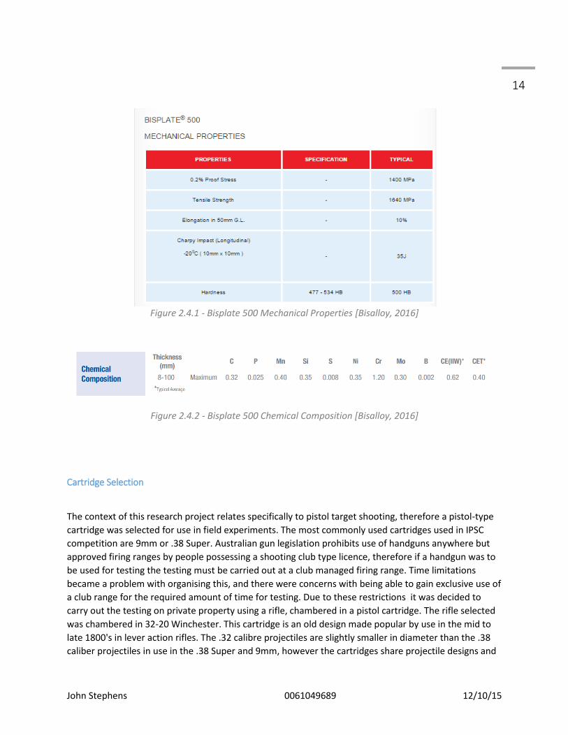
The material selected for the experimental phase of this research project is Bisalloy Bisplate 500.
Bisplate 500 is an armour grade plate designed to be extremely hard and the 500 in the products name
refers to its Brinell hardness score. For comparison, mild steel scores around 120HB. Bisplate 500 is a
commonly used material for sport shooting targets. Bisplate 500 is a very commonly used target
material due to its availability and price.
John Stephens 0061049689 12/10/15
14
Figure 2.4.1 - Bisplate 500 Mechanical Properties [Bisalloy, 2016]
Figure 2.4.2 - Bisplate 500 Chemical Composition [Bisalloy, 2016]
Cartridge Selection
The context of this research project relates specifically to pistol target shooting, therefore a pistol-type
cartridge was selected for use in field experiments. The most commonly used cartridges used in IPSC
competition are 9mm or .38 Super. Australian gun legislation prohibits use of handguns anywhere but
approved firing ranges by people possessing a shooting club type licence, therefore if a handgun was to
be used for testing the testing must be carried out at a club managed firing range. Time limitations
became a problem with organising this, and there were concerns with being able to gain exclusive use of
a club range for the required amount of time for testing. Due to these restrictions it was decided to
carry out the testing on private property using a rifle, chambered in a pistol cartridge. The rifle selected
was chambered in 32-20 Winchester. This cartridge is an old design made popular by use in the mid to
late 1800's in lever action rifles. The .32 calibre projectiles are slightly smaller in diameter than the .38
caliber projectiles in use in the .38 Super and 9mm, however the cartridges share projectile designs and

John Stephens 0061049689 12/10/15
15 both can fire a 115 grain (7.45 gram) projectile. The rifling twist rate in the weapon was 1:12" meaning
the projectile completes one full revolution in every 12 inches of forward travel. This was used to
calculate the average angular velocity of the projectile at 10400 rad/s .
Chapter 3 - Safety and Risk
General Risk Management
The planned experiments for this research project involve risks, mostly through the involvement of
firearms as an energy source, however these risks can be managed through careful planning and
responsible management. The University of Southern Queensland's Risk Management Plan has been
used to assess the hazards and the complete document can be found in appendix A.
The nature of this experiment was to establish the behaviors of bullets to minimise risk to shooters,
however to carry out the experiment it is necessary to put people in the vicinity of the bullet impacts.
This is relatively safe, however eye protection will be mandatory during testing as the eyes are the only
part of the body vulnerable to bullet fragments.
The primary control to minimise risk in the experiment is limiting access to people during the process.
The only people who will be permitted in the testing area will be the researching student (John
Stephens) and Ash Proud who is a licensed armourer and firearms safety instructor. Both Ash and John
have grown up involved in shooting sports and have a great respect for the danger of firearms handled
incorrectly.
Standard range rules will apply to the testing, there will be a nominated range officer to ensure all
firearms are only loaded when in use and immediately cleared on completion of individual tests. Only
two people will be present during testing.
Commercial Risk Management
The commercial risk of this experiment was low as the only equipment exposed to reasonable risk of
damage was a digital chronograph valued at $300.00. The chronograph is commonly used for the
intended purpose of accurately measuring projectile velocity and when set up correctly will be safely out
of the projectile flight path.

John Stephens 0061049689 12/10/15
16 Project Planning
The project was conducted in the following phases:
Research Phase- covering the academic research component, looking for as much data as
possible before physical testing occurs, to try and predict the testing outcomes.
Simulation Phase- Using ANSYS software a computer simulation of projectile impacts on
hardened steel plate will be
Experimentation phase- multiple days will be spent testing to collect all the required data.
Data analysis phase- studying all collected data, and identifying significant figures.
Write up phase- collaborating results and preparing the project dissertation.
Resource Requirements
Resources include:
Resource Supplier Cost Importance
ANSYS Software USQ USQ possesses an ANSYS licence.
Critical
Target test plates LOInnvations/ City of Brisbane Pistol Club
Donated Critical
Firearms A.N Proud Gunsmithing On Loan Critical
Test frame including paper support for tracking bullet splatter
LOInnovations On Loan Critical
Ammunition loading equipment and scales
A.N Proud Gunsmithing On Loan Critical
Digital Chronograph A.N Proud Gunsmithing On Loan Critical
Table 3.2.1 - Project Resources
John Stephens 0061049689 12/10/15
17 Chapter 4 - Methodology
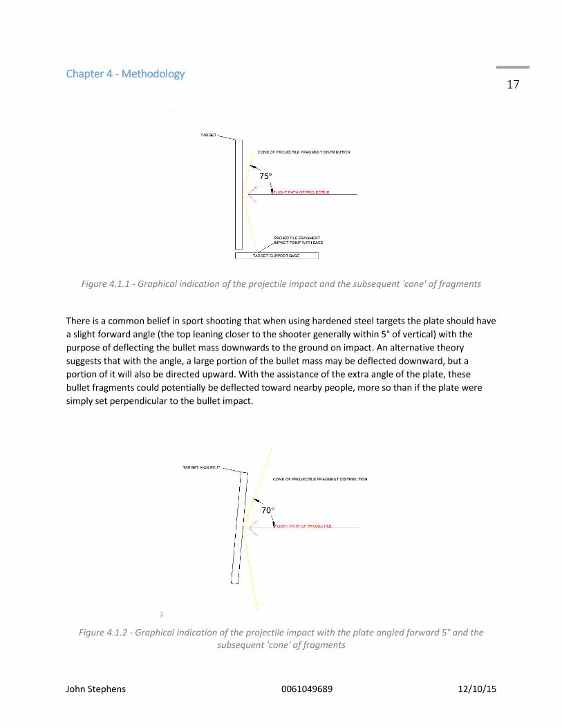
Figure 4.1.1 - Graphical indication of the projectile impact and the subsequent 'cone' of fragments
There is a common belief in sport shooting that when using hardened steel targets the plate should have
a slight forward angle (the top leaning closer to the shooter generally within 5° of vertical) with the
purpose of deflecting the bullet mass downwards to the ground on impact. An alternative theory
suggests that with the angle, a large portion of the bullet mass may be deflected downward, but a
portion of it will also be directed upward. With the assistance of the extra angle of the plate, these
bullet fragments could potentially be deflected toward nearby people, more so than if the plate were
simply set perpendicular to the bullet impact.
Figure 4.1.2 - Graphical indication of the projectile impact with the plate angled forward 5° and the subsequent 'cone' of fragments
John Stephens 0061049689 12/10/15
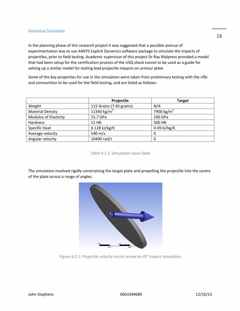
18 Numerical Simulation
In the planning phase of this research project it was suggested that a possible avenue of
experimentation was to use ANSYS Explicit Dynamics software package to simulate the impacts of
projectiles, prior to field testing. Academic supervisor of this project Dr Ray Malpress provided a model
that had been setup for the certification process of the USQ shock tunnel to be used as a guide for
setting up a similar model for testing lead projectile impacts on armour plate.
Some of the key properties for use in the simulation were taken from preliminary testing with the rifle
and ammunition to be used for the field testing, and are listed as follows:
Projectile Target
Weight 115 Grains (7.45 grams) N/A
Material Density 11340 kg/m3 7900 kg/m3
Modulus of Elasticity 15.7 GPa 200 GPa
Hardness 11 HB 500 HB
Specific Heat 0.128 kJ/kg/K 0.49 kJ/kg/K
Average velocity 540 m/s 0
Angular velocity 10400 rad/s 0
Table 4.2.1: Simulation Input Data
The simulation involved rigidly constraining the target plate and propelling the projectile into the centre
of the plate across a range of angles.
Figure 4.2.1: Projectile velocity vector arrow on 45° impact simulation
John Stephens 0061049689 12/10/15
19
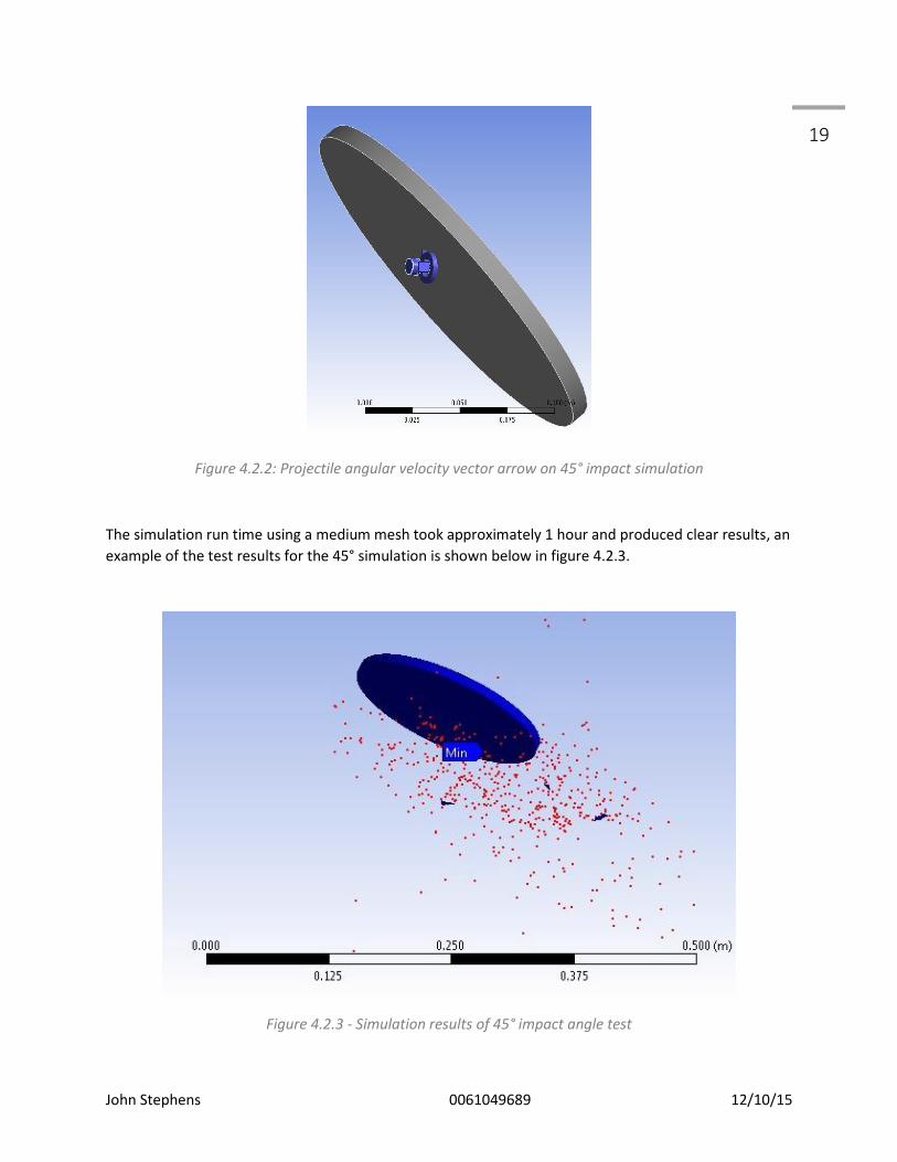
Figure 4.2.2: Projectile angular velocity vector arrow on 45° impact simulation
The simulation run time using a medium mesh took approximately 1 hour and produced clear results, an
example of the test results for the 45° simulation is shown below in figure 4.2.3.
Figure 4.2.3 - Simulation results of 45° impact angle test
John Stephens 0061049689 12/10/15
20 Field Testing
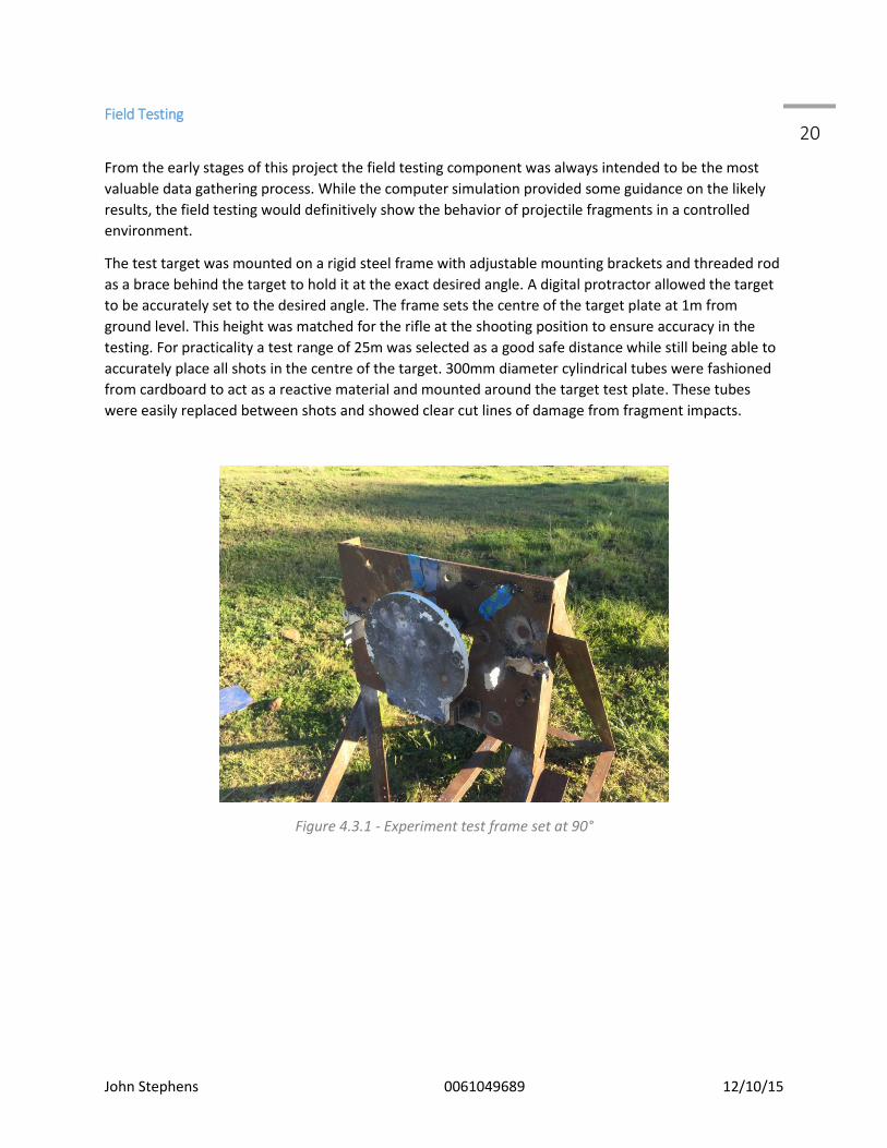
From the early stages of this project the field testing component was always intended to be the most
valuable data gathering process. While the computer simulation provided some guidance on the likely
results, the field testing would definitively show the behavior of projectile fragments in a controlled
environment.
The test target was mounted on a rigid steel frame with adjustable mounting brackets and threaded rod
as a brace behind the target to hold it at the exact desired angle. A digital protractor allowed the target
to be accurately set to the desired angle. The frame sets the centre of the target plate at 1m from
ground level. This height was matched for the rifle at the shooting position to ensure accuracy in the
testing. For practicality a test range of 25m was selected as a good safe distance while still being able to
accurately place all shots in the centre of the target. 300mm diameter cylindrical tubes were fashioned
from cardboard to act as a reactive material and mounted around the target test plate. These tubes
were easily replaced between shots and showed clear cut lines of damage from fragment impacts.
Figure 4.3.1 - Experiment test frame set at 90°
John Stephens 0061049689 12/10/15
21
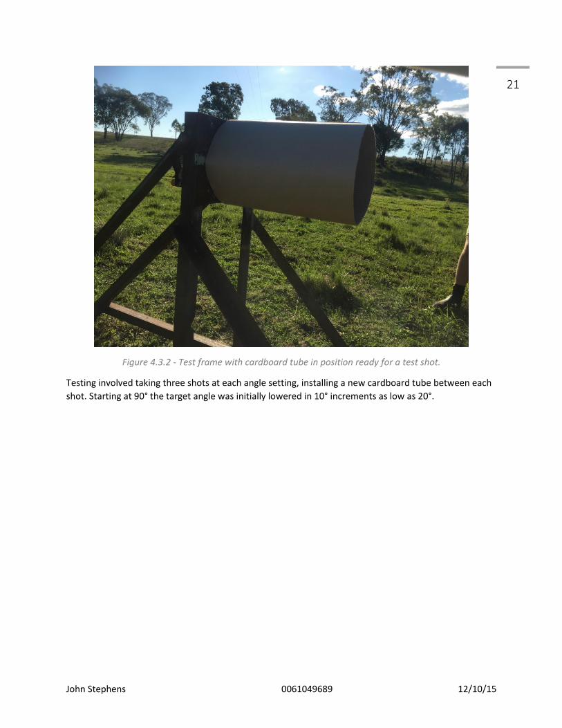
Figure 4.3.2 - Test frame with cardboard tube in position ready for a test shot.
Testing involved taking three shots at each angle setting, installing a new cardboard tube between each
shot. Starting at 90° the target angle was initially lowered in 10° increments as low as 20°.

John Stephens 0061049689 12/10/15
22 Chapter 5 - Results
Field Testing
The most significant observation taken from both the field testing and the ANSYS simulations was that
the majority of the projectile fragments were propelled away from the impact point on the same plane
as the target face. The fragment pattern was circular, with even distribution around the circle at a
perpendicular impact angle. As the target angle reduced (with the top of the target leaning closer to the
shooting position), the distribution of the fragments began to thin at the top of the circle until
eventually there was a noticeable gap and the circle was no longer complete.
Figure 5.1.1 - Resulting damage of a 60° test shot, it should be noted that the distribution of fragments
has begun to thin across the top of the circle, but it is still complete.

John Stephens 0061049689 12/10/15
23
27.5° was the shallowest impact angle where the arc consistently contained fragments. Anything below
this angle created an arc of undamaged cardboard at the top of the circle.
Figure 5.1.2 - CAD depiction of target at 27° impact angle and subsequent arc with no fragment damage
to cardboard
At a 25° impact angle there was an arc measuring approximately 35° at the top of the circle where there
were no identifiable fragment impacts. Fine angle adjustments and further testing found that at 26° of
impact angle the arc reduced to 30°, then at 26.5° the arc was reduced to 25°. The findings of these
adjustments are listen in Table 5.1.1.
The critical points identified are as follows:
27.5° - The lowest impact angle at which projectile fragments can be identified travelling directly
upward from the impact site, back toward the shooting position.
24° - The impact angle at which point there is no longer any projectile fragments being deflected upward
from the impact site.
20° - The point at which the projectile fragments deflect off the target face in such a manner that an arc
of distribution can no longer be observed.

John Stephens 0061049689 12/10/15
24
Figure 5.1.3 - Projectile Impact Angle vs Arc Angle
The general measurements of the damage to the cardboard tubes was compiled and the average found
for each angle. There were slight differences between the angles of the target plate and the angle of the
damage line through the tube, however the differences are small and inconsistent and no conclusions
can be taken from them. The differences can be explained by error in the measuring process due to the
jagged edges produced by the fragments travelling through the cardboard
Target Angle Measured Fragment Angle
90° 90°
80° 78.8°
70° 69.7°
60° 58.1°
45° 44.9°
40° 40.1°
35° 36.9°
30° Angles below 35° became hard to accurately measure, however the results remained consistent with earlier test angles and the fragment pattern remained co-planar with the target face.
25°
20°
Table 5.1.1 - Target angles with corresponding fragment damage line angles
Paper was used as a reactive medium to indicate any significant fragments being projected back toward
the shooting position. Damage to these sheets of paper was minimal and not present in every test shot.
The largest hole measured in the paper was 0.8mm across, which was small in comparison to the
damage on the cardboard surrounding the target surface. The ANSYS simulations also showed some
0
5
10
15
20
25
30
35
40
25 26 26.5 27 27.5
Arc
An
gle
Impact Angle
Impact Angle vs Arc Angle

John Stephens 0061049689 12/10/15
25 outlying fragments beyond the target face plane but these can be considered anomalies in the
simulation as the results were not consistent with the field testing or between various ANSYS
simulations.
Fragments flying back toward shooting position
Figure 5.1.4- 0.8mm wide hole in paper indicating a stray fragment

John Stephens 0061049689 12/10/15
26 ANSYS Simulation
The results from the ANSYS simulations are best shown in visual form, and the following section includes
multiple images of the test results at particular angles. The simulations were, for the most part, very
similar to the results obtained in the field testing. The key difference between the two was the impact
angle at which the fragments were predominantly deflected downwards. The arc described in the field
test results where there was no longer any damage present at the top of the fragment damage circle
became apparent at a 65° impact angle. The 45° simulation images show the distribution of the
fragments to be almost completely below the impact point, whereas the field testing revealed that even
at an impact angle as low as 25° there was still a noticeable portion of the fragments impacting the
cardboard above the impact point.
Figure 5.2.1- Front view of the fragment distribution in 90° impact angle simulation. This simulation did
produce an interesting pattern in the fragments due to the angular velocity of the projectile.
John Stephens 0061049689 12/10/15
27
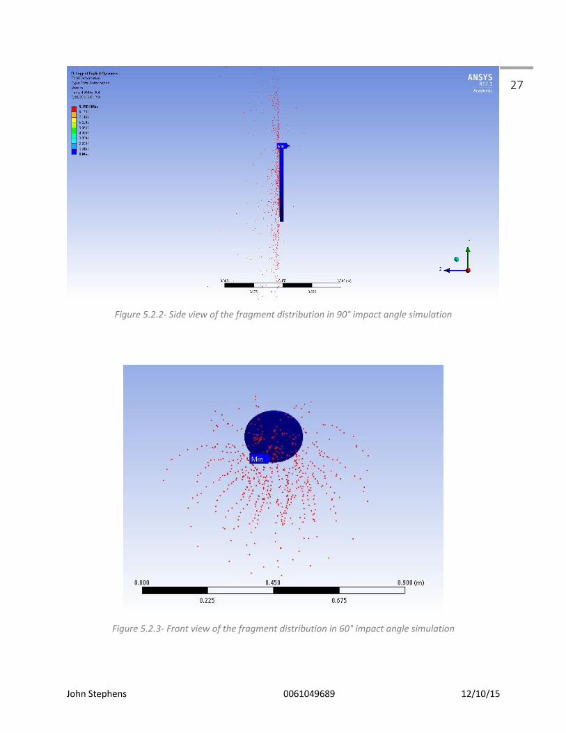
Figure 5.2.2- Side view of the fragment distribution in 90° impact angle simulation
Figure 5.2.3- Front view of the fragment distribution in 60° impact angle simulation

John Stephens 0061049689 12/10/15
28
Figure 5.2.4- Side view of the fragment distribution in 60° impact angle simulation
The 60° impact simulation showed a noticeable thinning of fragment distribution at the top of the circle,
similar to what was observed in the field testing around 27°.
Figure 5.2.5- Side view of the fragment distribution in 45° impact angle simulation
John Stephens 0061049689 12/10/15
29
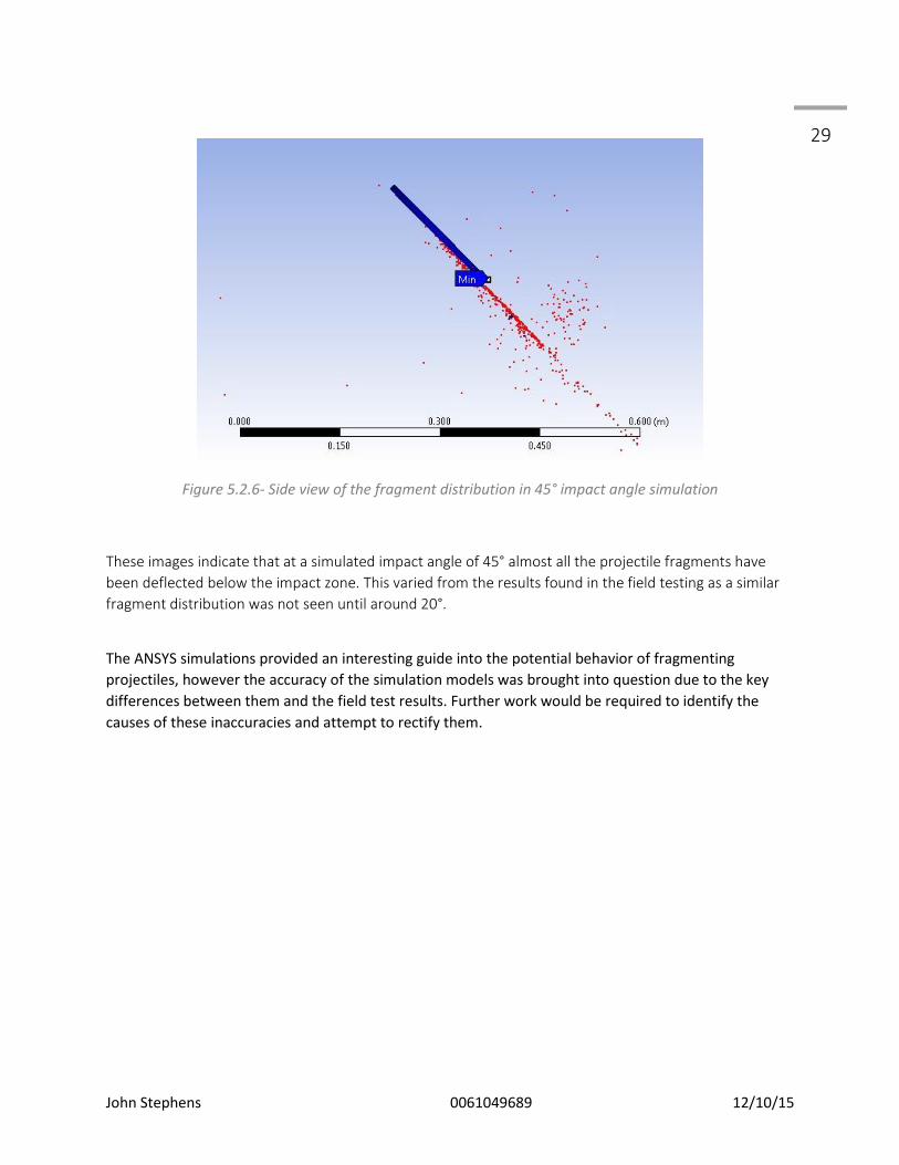
Figure 5.2.6- Side view of the fragment distribution in 45° impact angle simulation
These images indicate that at a simulated impact angle of 45° almost all the projectile fragments have
been deflected below the impact zone. This varied from the results found in the field testing as a similar
fragment distribution was not seen until around 20°.
The ANSYS simulations provided an interesting guide into the potential behavior of fragmenting
projectiles, however the accuracy of the simulation models was brought into question due to the key
differences between them and the field test results. Further work would be required to identify the
causes of these inaccuracies and attempt to rectify them.

John Stephens 0061049689 12/10/15
30
Chapter 6 - Conclusions and Recommendations
The most significant finding of this research project was that contrary to common belief, the projectile
fragments were almost completely contained within the plane of the target surface. This leads to the
conclusion that the safest place for any person to be in relation to a hardened steel target is as far from
the plane created by the target face as possible. it was expected before the experiments were
undertaken that the projectile fragments would be projected in a conical shape with the point of the
cone at the impact site on the target face, as is depicted in figure 2.1.1, but this was not the case.
Repeated tests proved that the flat surface of the target face created a plane that contained the vast
majority of the projectile fragments.
Figure 6.1.1 - The clear cut line of fragment damage to the testing cardboard indicating the projected
plane on which the fragments travel.
The idea that leaning a target toward the shooting position makes use of the target safer is untrue.
While it is true that eventually as the target is leant further toward the shooting position the amount of
fragments projected back toward the shooters will reduce to zero, this angle is far beyond what a target
will ever be practically set to. Any impact angle greater than 40° will still project a large portion of the
projectile mass toward the shooting position. An angle such as that shown in figure 6.1.1

John Stephens 0061049689 12/10/15
31
With the projectile fragments being predominantly contained inside of such a shallow plane they would
be relatively easy to contain with a loop of absorbent material such as rubber conveyor belting.
Conveyor belting is sometimes used to hang targets and has proven to be hard wearing against damage
from projectile fragments. With the design of IPSC range layouts constantly changing a method of
containing fragments such as a simple loop above the target is likely to be the most effective method as
it will contain the projectile fragments even if a shooter hits the target on an shallow angle.
Figure 6.1.2 - a CAD model depicting a possible position of a rubber conveyor belt loop to contain
projectile fragments.

John Stephens 0061049689 12/10/15
32 Bibliography
Jauhari, M. Illinois, USA 1969. 'Bullet Ricochet from Metal Plates' The Journal of Criminal Law, Criminology and Police Science, Volume 60 pages 387 - 397
Rosenberg, Z. Dekel, E. Springer Heidelberg, London 2012 Terminal Ballistics Safety, Steel Shooting Guidelines -- Spectre Targets LLC. 2015. Safety, Steel Shooting Guidelines -- Spectre Targets LLC. [ONLINE] Available at: http://spectretargets.com/steel_shooting_guidelines.html. [Accessed 23 August 2015]. Barış İrhan, Joško Ožbolt, Daniela Ruta, Institute for Construction Materials, University of Stuttgart, 70569 Stuttgart, Germany '3D finite element simulations of high velocity projectile impact' International Journal of Solids and Structures Vermeij, E, Rijnders, M, Pieper, P, Hermsen, R, Netherlands Forensic Institute, The Hague, The Netherlands 2012 'Interaction of bullets with intermediate targets: Material transfer and damage' Forensic Science International Volume 223, Issues 1-3 Haag, Michael G. Haag, Lucien C. Forensic Science Consultants, Albuquerque, New Mexico 2011 'Projectile Ricochet and Deflection' Shooting Incident Reconstruction (Second Edition), 2011, Pages 143–174 HOULDEN, M A, Department of Physics, University of Liverpool, Liverpool, United Kingdom L69 3BX 'The distribution of energy among fragments of ricocheting pistol bullets' Journal of the Forensic Science Society 1994 Zukas, J.A., Gaskill, B. Computational Mechanics Consultants, Inc, Baltimore, MD, U.S.A 1995 'Ricochet of deforming projectiles from deforming plates' International Journal of Impact Engineering, Volume 18, Issue 6, September 1996 Børvik, T Olovsson L Dey, S Langseth, M 'Normal and oblique impact of small arms bullets on AA6082-T4 aluminium protective plates' International Journal of Impact Engineering, Volume 38, Issue 7, July 2011, Pages 577–589 Segletes, Steven B. US Army Research Laboratory, USA 2004 'A model for rod ricochet' International Journal of Impact Engineering, Volume 32, Issue 9, September 2006, Pages 1403–1439 Malbranque, S, Jousset, N, Nedelcu, C, Rougé-Maillart, C, Department of Forensic Medicine, Angers University Hospital, Angers, France, 2014

John Stephens 0061049689 12/10/15
33 'Bone-patch type secondary projectiles: A report on two shots fired at point-blank range using hollow point bullets' Forensic Science International, Volume 245, December 2014, Pages e6–e10 W. Johnson,A.K. Sengupta S.K. Ghosh Department of Engineering, University of Cambridge, Cambridge, England 2003 ' Plasticine modelled high velocity oblique impact and ricochet of long rods' International Journal of Mechanical Sciences Volume 24, Issue 7, 1982, Pages 437-455 Iqbal, M.A, Gupta, G. Gupta, N.K., Department of Civil Engineering, Indian Institute of Technology Roorkee, Roorkee, India 2009 3D numerical simulations of ductile targets subjected to oblique impact by sharp nosed projectiles International Journal of Solids and Structures Volume 47, Issue 2, 15 January 2010, Pages 224–237.
Thales Australia, 2013. ADI Powders Handloaders' Guide. [Online] Available at: www.adi-powders.com.au/handloaders-guide/.

John Stephens 0061049689 12/10/15
34
Appendix A - Project Specification
ENG4111/4112 Research Project
Project Specification
For: John Stephens
Title: Projectile mass distribution after impact with hardened steel plate.
Major: Mechanical engineering
Supervisors: Dr. Ray Malpress, USQ School of Mechanical Engineering
Enrolment: ENG4111 – EXT S1, 2016 ENG4112 – EXT S2, 2016
Project Aim: To study the behavior of lead projectiles after impact with hardened steel plate, and the
effect that changing the impact angle has on the directional distribution of the projectile mass.
Programme: Issue A, 16th March 2016
1. Examine previous research on similar topics and extract relevant data to assist forming theories about
bullet behavior prior to practical testing.
2. Design experiment details and establish limitations ie. what range of impact angles are likely to
produce useful data.
3. Perform experiments and collect data. Assess if any variations need to be made to experiments to
collect useful data. The practical testing of this project will be the first major milestone as until this occurs
the theoretical work will not have a large amount of support.
4. Analyse collected data and establish trends of mass distribution across the experimental parameters.
5. Extrapolate data to establish guides for use of hardened steel plate in sport shooting. The translation of
the findings to form useful guidelines for sport shooting clubs will be a significant milestone as a large
portion of the value of this research is tied to its relevance and usefulness to these clubs.
6.Present findings to USQ peers and supervisors during Professional Practice 2 residential school.
7. Collaborate findings and write dissertation document. The completion of the dissertation will be the
final major milestone of the research project.
If time and resources permit: 8. Recommend possible hardware additions to steel targets to improve safe use.

John Stephens 0061049689 12/10/15
35 Appendix B - Risk Management Plan

John Stephens 0061049689 12/10/15
36

John Stephens 0061049689 12/10/15
37 Appendix C - Testing Equipment and Consumables
Equipment:
RCBS Chronograph
Target Support Frame
Lithgow Rifle chambered in 32-20 Winchester
Digital Protractor
Vernier calipers
Ø200mm Round Bisplate 500 Target Plate
Portable Bench
Lexan Polycarbonate Blast Screen
Rifle Bracing Sandbags
Earmuffs
Digital Camera
Consumables:
.32 Caliber 115gr Lead-Tin alloy projectiles
ADI AR2208 Smokeless Gunpowder
Remington Small Pistol Primers
Single Side Cardboard (1.5m x 34m)
Waxed Paper

John Stephens 0061049689 12/10/15
38
Appendix D- Field Testing Data compiled in Solidworks
Screenshot showing the compilation of measurements taken during field testing using Solidworks to
calculate angles.