PROJECTDOX VISUALIZATION TOOL GUIDE - · PDF fileProjectDOx ® Visualization Tool Guide ......
66
1 PROJECTDOX ® VISUALIZATION TOOL GUIDE Introduction This guide provides an overview of the ProjectDox Viewer and provides exercises for the most commonly used features. This guide is designed for end users who are using their browsers to view documents, via web page links, that were processed and cached through the ProjectDox Server. The ProjectDox Viewer allows users to view, zoom, pan, rotate, measure, annotate, and redact documents and images quickly and easily. Product Version Information 7.0 SR1 Version 1.1 Created by: Nikki Thorne
Transcript of PROJECTDOX VISUALIZATION TOOL GUIDE - · PDF fileProjectDOx ® Visualization Tool Guide ......

1
PROJECTDOX® VISUALIZATION TOOL
GUIDE
Introduction This guide provides an overview of the ProjectDox Viewer and provides exercises for the most commonly used features. This guide is designed for end users who are using their browsers to view documents, via web page links, that were processed and cached through the ProjectDox Server. The ProjectDox Viewer allows users to view, zoom, pan, rotate, measure, annotate, and redact documents and images quickly and easily.
Product Version Information 7.0 SR1 Version 1.1 Created by: Nikki Thorne

2
Table of Contents ProjectDOx® Visualization Tool Guide ........................................................................................................... 1
Introduction .......................................................................................................................................... 1
Product Version Information 7.0 SR1 ................................................................................................... 1
Introduction .............................................................................................................................................. 4
ProjectDox Visualization Tool ................................................................................................................... 4
ProjectDox Visualization Interface ............................................................................................................... 4
ProjectDox Visualization Display Toolbar ............................................................................................. 5
Training Exercises .......................................................................................................................................... 6
How to turn on and off layers of DWG files .................................................................................................. 6
How to use the Search and Measurement Features .................................................................................... 7
Fig.1 ........................................................................................................................................................... 8
How to Use the Measurement Tool and File Scale ....................................................................................... 9
How to use the Search and Measure Count features ................................................................................. 10
How to add Markups to a file ..................................................................................................................... 11
Fig.2 – Wheel Chair Access Issue ............................................................................................................ 12
How to Adjust the Size of a Markup ........................................................................................................... 14
How to Resize a Markup ............................................................................................................................. 15
How to Open Existing Markups in ProjectDox ............................................................................................ 15
How to Review Existing Changemarks ........................................................................................................ 16
How to Edit an Existing Markup Layer ........................................................................................................ 17
Adding More Markups ................................................................................................................................ 18
Fig. 4.2 – Verify Egress ............................................................................................................................ 20
How to Use Measurement Count Takeoffs ................................................................................................. 21
How to Use Measure Takeoffs .................................................................................................................... 23
Negative Area checkbox .......................................................................................................................... 24
How to remove delete a measurement .................................................................................................. 25
How to resize a measurement ................................................................................................................ 25
How to Use the Strikeout Feature .............................................................................................................. 25
How to Compare File Versions .................................................................................................................... 26
How to Compare Markup File Versions ...................................................................................................... 27
How to Compare Text Files ......................................................................................................................... 28
How to Compare Two File Versions ............................................................................................................ 29
How to Compare File Versions and Set Alignment Points .......................................................................... 30
Fig.5 ......................................................................................................................................................... 31
How to Use the Nudge Feature .................................................................................................................. 33

3
How to Extract ChangeMarks ..................................................................................................................... 33
How to Add a Image Stamp ........................................................................................................................ 34
Fig.4.3 ...................................................................................................................................................... 35
Fig.4.4 ...................................................................................................................................................... 35
How to create a Stamp Template ............................................................................................................... 36
How to Add a Markup Stamp ...................................................................................................................... 40
How to Create a Batch Stamp Template ..................................................................................................... 40
How to Use the Redaction Tool .................................................................................................................. 41
How to Publish Markups ............................................................................................................................. 42
How to use Redact to Phrase List & Redact by Phrase ............................................................................... 43
How to Print a File ....................................................................................................................................... 45
How to Add and Edit Watermarks/Banners ............................................................................................... 46
Fig.6 ......................................................................................................................................................... 47
Toolbars................................................................................................................................................... 48
Main Toolbar ....................................................................................................................................... 48
ProjectDox Visualization Enterprise Functions Menu ......................................................................... 48
ProjectDox Viewer Display Toolbar..................................................................................................... 55
ProjectDox Compare Toolbar .................................................................................................................. 57
Set Alignment Tools ............................................................................................................................ 58
Tool Properties Toolbar .......................................................................................................................... 59
ProjectDox Viewer Task Pane ................................................................................................................. 61
HOT KEYS ..................................................................................................................................................... 64
HOT KEYS ................................................................................................................................................. 64

4
Introduction
ProjectDox Visualization Tool If you have not installed the ProjectDox Components from the Login Page the first time you access a published document for viewing through your browser, you will be required to download the ProjectDoxClientX control onto your system. Some network administrators require users have Administrative rights to their PC to install ActiveX components. If you are unable to successfully install contact your IT department to get sufficient rights to install this software. If you have sufficient rights and have not installed from the Login Page you will be prompted once you select a file for the first time. The ActiveX security alert will display at the top of the page requesting a right-click to allow the install. Once installed, if you have ActiveX controls blocked in your browser option settings, you will need to select Allow Blocked Content from the IE Security bar when prompted.
ProjectDox Visualization Interface

5
ProjectDox Visualization Display Toolbar All users granted permission to view files in ProjectDox have access to the below general features from the user interface. Additionally, there are keyboard hot keys available and additional right-click features that can be accessed while reviewing files.
The ProjectDox Viewer display toolbar contains tools to control how images display.
Color. Use this button to change the background color of file types with "transparent" background colors, such as monochrome raster and vector file types (color raster files are not affected) to black, white, or gray.
Monochrome: Available from the color menu is also the Monochrome setting. Turning on Monochrome change all lines of a color vector image to a single color (the default is black) while leaving markup entities in color for quick identification.
Set Visible Layers. Turn image layers (e.g., layers of a DWG file) on or off to minimize clutter in the view window or to focus on a particular area or part.
Rotate. The Rotate button allows you to rotate the image in 90 degree clockwise increments.
Fit All. Returns the zoom level to 100% so the full image displays in the ProjectDox window.
Fit Width. Ideal for 8.5” X 11” office documents, Zoom Width changes the zoom level so that the entire width of the image appears in the window. You can read rows of text without having to scroll right and left to see the entire line.
Zoom Slider. You can move the slider ball from left to right to increase or decrease magnification. Move left to decrease, right to increase. The ball snaps back to center on release.
Pan/Zoom. When zoomed in on an image, use the Pan tool to maneuver around the image.
6
Magnifier. Use the Magnifier to summon a magnified view window on your image. The magnification can be adjusted and a toggle tool is
available to allow you to switch between eye glass , bird’s eye
, and docking behavior .
Page Control. Use page control to navigate through the pages of your documents. You can select a specific page from the drop-down list.
Training Exercises The ProjectDox viewer contains a variety of tools and features to assist in review and marking up of electronic plans and documents. The following section provides exercises to familiarize you with some of the more common tools used when reviewing plans and can be used as a resource reference
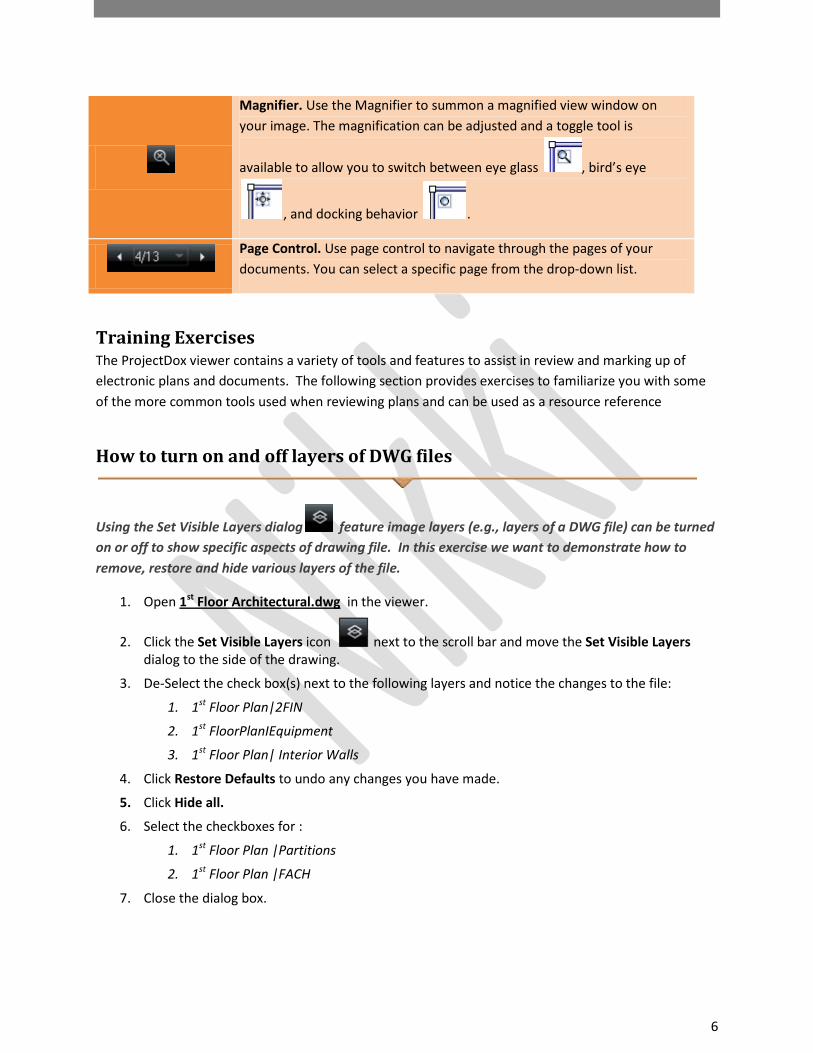
How to turn on and off layers of DWG files
Using the Set Visible Layers dialog feature image layers (e.g., layers of a DWG file) can be turned on or off to show specific aspects of drawing file. In this exercise we want to demonstrate how to remove, restore and hide various layers of the file.
1. Open 1st Floor Architectural.dwg in the viewer.
2. Click the Set Visible Layers icon next to the scroll bar and move the Set Visible Layers dialog to the side of the drawing.
3. De-Select the check box(s) next to the following layers and notice the changes to the file:
1. 1st Floor Plan|2FIN
2. 1st FloorPlanIEquipment
3. 1st Floor Plan| Interior Walls
4. Click Restore Defaults to undo any changes you have made.
5. Click Hide all.
6. Select the checkboxes for :
1. 1st Floor Plan |Partitions
2. 1st Floor Plan |FACH
7. Close the dialog box.

7
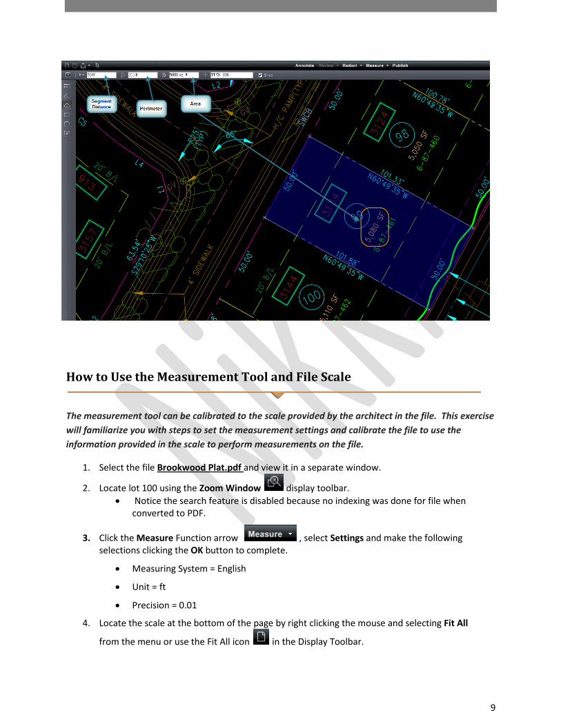
How to use the Search and Measurement Features
The search feature allows text contained in a document or drawing to be searched. You can search using parameters such as Match Case, Find Whole Word Only, wildcards and even macros allowing for quicker recognition of aspects within a file.
The measurement feature provides a set of tools that can be used for drawing and images files. When using the measurement tool you should first set a standard measurement scale or calibrate a baseline distance to use as a scale by selecting the Measurement function and Measurement Settings dialog. The dialog allows you to select the scale factor to use, and precision units for measurement value display results when using the measurement tools (distance, area, angle, xy value, and perimeter). The measurement tool uses an interval of 0 to 360 degrees for all angular measurements.
The following exercises we will use the search feature to locate specific values in the “Brookwood Plat.dwg” file and use the measurement tool to determine size, distance etc.
1. Select the file Brookwood Plat.dwg from the thumbnail view.
2. Locate section 100 in this file by typing 100 into the Search dialog box in the top right of the viewer.
3. Click the Measure Function arrow in the Main Toolbar and select Settings. Make the following selections and click the “OK” button to complete.
• Measuring System = English
• Unit = ft
• Precision = 0.01

8
4. Click the Measure Function arrow and select Calibrate.
5. Place a checkmark to use the Snap feature.
• Snap is only available for CAD-Like formats
6. Click the left mouse button on the first point then the last point (just pass the green line)in the distance to use as the baseline as seen below.
7. Enter the value of 101.88 8. Click OK
Fig.1
9. Select to activate the Measure toolbar to the left hand side of the viewing area
and select to measure a single line.
10. Using the line measurement verify the measurements for each of the four sides of Section 100. You should notice that the measurements match what has been entered on the file.
Now let’s measure another section of the file and find its square footage using another measurement feature called Measure Polygon.
11. Select Measure Polygon and measure section 99 to find the square footage.
12. Select a corner of section 99 and perform a left mouse click move to the next section point and left click on each corner covering the space for calculation.
13. To release and calculate the distance and square footage click the right mouse button.
• The calculations will display in the Main Toolbar including segment distance, perimeter and area. For this example the square footage or area will match the area/square footage indicated on the drawing file (5,080 SF).
9
How to Use the Measurement Tool and File Scale
The measurement tool can be calibrated to the scale provided by the architect in the file. This exercise will familiarize you with steps to set the measurement settings and calibrate the file to use the information provided in the scale to perform measurements on the file.
1. Select the file Brookwood Plat.pdf and view it in a separate window.
2. Locate lot 100 using the Zoom Window display toolbar. • Notice the search feature is disabled because no indexing was done for file when
converted to PDF.
3. Click the Measure Function arrow , select Settings and make the following selections clicking the OK button to complete.
• Measuring System = English
• Unit = ft
• Precision = 0.01
4. Locate the scale at the bottom of the page by right clicking the mouse and selecting Fit All
from the menu or use the Fit All icon in the Display Toolbar.

10
5. Click the Measure Mode arrow and click Calibrate.
6. Select the Snap feature.
7. Choose your first point on the scale as 0 and the second point 120.
8. Type in the distance in the dialog box to be 120 to match the scale and click OK.
9. Verify the measurements for each of the four sides of Section 100.
• Measurements of PDF files are typically 1/100th of an inch off the original measurement due to file conversion. This is has been deemed an acceptable and standard practice.
10. Select Measure Polygon and measure for the square footage of section 99
11. Select a corner of section 99 and perform a left mouse click move to the next section point and left click on each corner covering the space for calculation.
12. To release and calculate the distance and square footage click the right mouse button.
• The square footage calculated will display in the Main Toolbar and show the Segment Distance, Perimeter and Area calculated.
How to use the Search and Measure Count features
The Measure Count tool allows you to easily count items in a drawing - such as fixtures in a floor plan, screws on a design, etc. A marker is placed on the counted item to serve as a placeholder and when used with the search feature can be a powerful and time saving tool. In this exercise we will search a drawing file for all the Photoelectric Smoke Detectors which are indicated by the letter “P” in the file.
1. Select and view the file FP-1.dwg.
2. Enter the letter “P’ into the search window
3. Click the Find icon to locate the first instance of “P”
• Highlighted in blue
4. Select Measure to enable the Measure Toolbar to the left hand side of the viewing screen.
5. Select the Measure Count icon. 6. Click on an area close to the first instance of “P”
11
7. Select the Find icon again and place a checkmark on each instance of “P” in the file until there are no new instances.
• Notice that the measure count keeps track of the number of items found and their location.
• To remove the last count checkmark applied click the icon.
• To remove all count checkmarks select the icon.
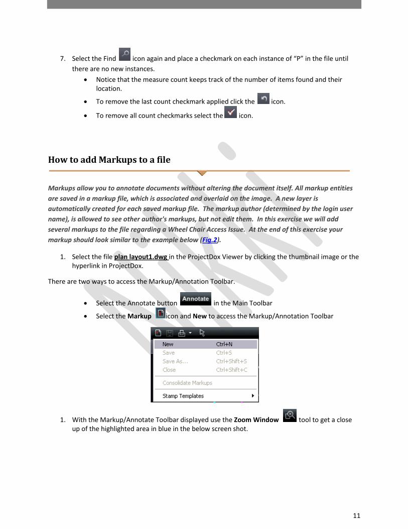
How to add Markups to a file
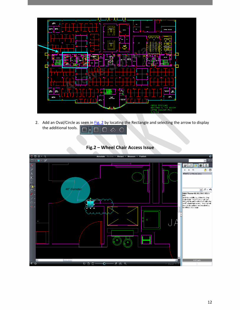
Markups allow you to annotate documents without altering the document itself. All markup entities are saved in a markup file, which is associated and overlaid on the image. A new layer is automatically created for each saved markup file. The markup author (determined by the login user name), is allowed to see other author's markups, but not edit them. In this exercise we will add several markups to the file regarding a Wheel Chair Access Issue. At the end of this exercise your markup should look similar to the example below (Fig.2).
1. Select the file plan layout1.dwg in the ProjectDox Viewer by clicking the thumbnail image or the hyperlink in ProjectDox.
There are two ways to access the Markup/Annotation Toolbar.
• Select the Annotate button in the Main Toolbar
• Select the Markup icon and New to access the Markup/Annotation Toolbar
1. With the Markup/Annotate Toolbar displayed use the Zoom Window tool to get a close up of the highlighted area in blue in the below screen shot.
12
2. Add an Oval/Circle as seen in Fig. 2 by locating the Rectangle and selecting the arrow to display the additional tools.
Fig.2 – Wheel Chair Access Issue

13
3. To change the color of the markup select from the Markup Properties Toolbar to display a 16 standard color palette to choose from.
4. Choose “Highlight” from the Markup Properties Toolbar to make the markup transparent
allowing the background of the file to be viewed.
5. Optionally, a hyperlink can be added to the markup by selecting the link icon and entering the URL for the link.
• All markups will have the option to attach a hyperlink to another file, web page etc available.
6. Add the text 48” Diameter to the circle by selecting the Text icon and creating a box in the center of the circle as seen in Fig.2
• Adjust the size using the Markup Tool Bar properties or by using the yellow circle as seen in the green box in the below screen shot.
• To rotate the text box use the green circle as seen in the yellow box in the below screen shot.
7. Add a Changemark and cloud as seen in Fig. 2 to the file by selecting the icon. • Press the left mouse button and hold as you place the cursor (cursor is replica of the
icon selected) on the start point for the cloud location. • Drag the mouse with the left mouse button depressed across the page creating the
cloud around the desired object • Release the left mouse button to set the cloud in place and have the Changemark dialog
box appear. o The Changemark box will be in edit mode allowing you to re-position the
Changemark as needed. 8. A dialog will display. Add the following text:
• Name the Changemark “Wheel Chair Access Issue”. • In the subject area add: ADA Accessibility Guidelines Building Code Issue - 4.23 Move or
cut back wing wall in men's restroom to allow for a 48" wheelchair access. Drawings will need to be updated and resubmitted to reflect this change.
• Leave the defaults for the Type and State dropdowns. • Click the Ok button to close the Changemark.
9. Click the “Save As” icon and enter a unique markup name.
• Alternatively you may use Markup icon and select to “Save” the Markup Layer using a unique name. Example: BLD
• Markup layer names must be unique for the file. Duplicate file names can result in unexpected errors when viewing.

14
10. Exit the drawing file by clicking the red X in the upper right corner or by selecting the Markup
Save Icon and Close. 11. Return to the folder view in ProjectDox and refresh the folder panel (right click in the panel and
select refresh) and note the additional icon for plan layout1.dwg.
How to Adjust the Size of a Markup
1. Once a markup is placed on the file to make changes first select the Edit Markup/Select icon
. 2. Locate the desired markup with the cursor and click on it.
• The markup is available to edit when the image is outlined as seen below with the dotted area. The cursor will display four directional arrows in this mode allowing the markup to be moved on the file.
3. To move the image click the image and hold the left mouse button down on the markup dragging it to the desired location.
4. Release the mouse button and click the file to set the markup in the new location.

15
How to Resize a Markup
1. Once a markup is placed on the file use the Edit Markups icon to select the markup. 2. Left click and hold the mouse button for either circles found on both ends of the markup
dragging forward or backward until the desired length is achieved. 3. Release the left mouse button to set the markup.
How to Open Existing Markups in ProjectDox
There are multiple ways to open existing markups on a file. The markups can be accessed from the file view in ProjectDox by clicking the Markup Icon or by opening the file in the viewer and selecting
button in the Main Toolbar.
To open an existing Markup from the file thumbnail view:
1. Click the Markups icon on the plan layout1.dwg file to view the markups 2. Select the View checkbox next to your markup(s) and click the View/Edit button. 3. The Viewer will display a navigation pane to the right listing any Changemarks on the file.
• Review Changemark Navigation Pane only displays when the Changemark Note is applied to the file.
• Click the “Wheel Chair Access Issue”.
To open an existing Markup in the ProjectDox Viewer:
1. Select the file from the File View in ProjectDox
2. Select the from the Main Toolbar
3. The markup layer will be displayed
• If Changemark Notes were applied to the file the Review Changemarks Panel will display to the right of the viewing area.

16
How to Review Existing Changemarks
You or subsequent reviewers can view a list of all the Changemarks associated with an image through the Review Changemarks window. The Review Changemarks window should automatically open to the right if Changemarks are present on the file. If the window does not auto-populate follow steps 1-2 described below.
1. Click to open the Markup Open for Review dialog.
2. Select the markup layer and click “OK” to open the Changemark and the Review
Changemarks panel to the right of the viewing area.
• Existing Changemarks can be reviewed by title, author, or date by clicking the appropriate tab. You can add a search filter if desired. (Click All to return all Changemarks to the list.)
• Selection of the in the panel toolbar will display the Review Changemarks panel.
3. Click on a resulting Changemarks that you wish to view. The Changemarks text displays in the panel's lower frame.
4. You can progress sequentially through the Changemarks by using the Next and Previous
arrow buttons , by clicking the Changemark name in the panel or by selecting the
arrow and choosing appropriate selection from the dropdown.
• The Changemarks entities appear in the ProjectDox viewer at the same magnification level the author created them. To view the Changemark, the "Review Changemark" panel must be opened. To edit the Changemark, you must be the author, have the markup opened in edit (not review), and click the individual Changemarks you want to edit.
• You can extract information from one or all Changemarks contained in a document
through the Copy Changemarks dialog. Click to access this dialog.
• Any URL’s added to the Changemark will show in the body of the Changemark and open a new browser window to view the destination.
17
How to Edit an Existing Markup Layer
This exercise will demonstrate how to edit a markup that has been previously saved and the file closed. A file can be edited and saved using the Save As Icon as often as required without having to leave the file until the file is closed. Once the file is closed users must access the file to edit through the Markup Layers Panel in the file view of ProjectDox.
1. Select the Markup icon 2. Select the “Edit” radio button and click the “View/Edit” button 3. Select the Wheel Chair Access Issue from the navigation pane
4. Click the Edit Markups icon to enable the feature. 5. Double click the “Wheel Chair Access Issue” Changemark Note. 6. Add the following text:
Reference attached web link for more building code information regarding wheelchair access to public restrooms.
7. Click Ok
8. Select the hyperlink icon from the Tool Properties Toolbar. 9. Enter the below URL into the dialog box and click the Ok button.
http://www.access-board.gov/adaag/html/adaag.htm
10. Select the Markup Save icon to save your changes.
*You can add hyperlinks to any markup by using the Edit Markup icon and selecting the Add Hyperlink icon.
18
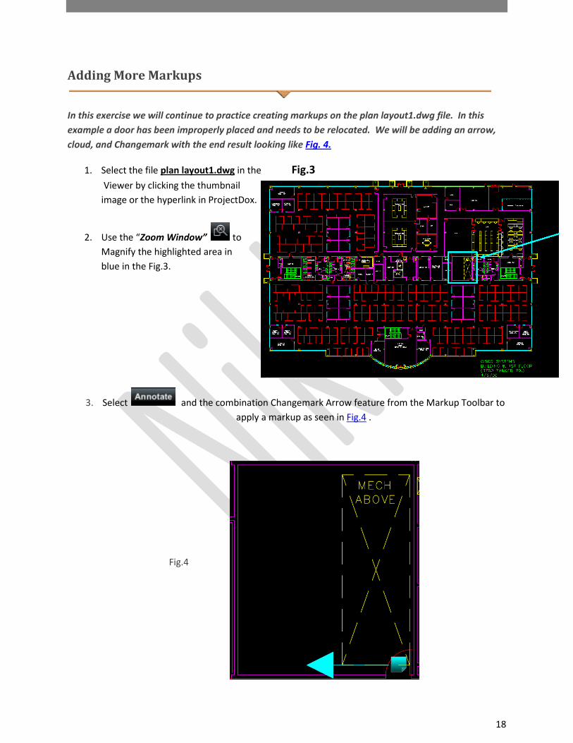
Adding More Markups
In this exercise we will continue to practice creating markups on the plan layout1.dwg file. In this example a door has been improperly placed and needs to be relocated. We will be adding an arrow, cloud, and Changemark with the end result looking like Fig. 4.
1. Select the file plan layout1.dwg in the Fig.3
Viewer by clicking the thumbnail image or the hyperlink in ProjectDox.
2. Use the “Zoom Window” to Magnify the highlighted area in blue in the Fig.3.
3. Select and the combination Changemark Arrow feature from the Markup Toolbar to apply a markup as seen in Fig.4 .
Fig.4

19
4. Place the cursor at the selection point holding the left mouse button down and dragging across the file creating the arrow.
• Releasing the mouse button will set the arrow and display the Changemark Note. 5. Type into the Changemark Note:
• Title = “Door Relocation Issue”.
• Body of Note = Check mechanical equipment above to make sure there is no conflict with the door opening into this room. Relocate the door to clear mechanical above. Resubmit drawing if changes are required.
• Click the Ok button to close the Changemark.
6. To Edit the arrow placement, size, color etc. select the Edit Markup Icon and click the arrow markup.
7. Select the color of the markup and adjust the width of the arrow lines using the Tool Properties
Toolbar.
• Notice that the Tool Properties Toolbar selections vary depending on the tool selected. 8. Use the Tool Properties Toolbar to adjust the color, size of the arrow or to adjust the type of
line (solid, dot, dash, dash-dot).
Any number of markups can be added to a single markup layer to practice this concept we will add another issue to this file related to the egress. 9. Locate the area indicated in the screenshot below (Fig 4.1) as shown by the yellow rectangle and
arrow in the upper left corner.

20
10. Click the line markup tool to select the polyline tool and markup off the travel distance from the Florida Room to the first available exit as show in the diagram below (Fig. 4.2).
Fig. 4.2 – Verify Egress
11. From the Markup Tool Bar Properties bar select the dot style with the desired width for the
line. (Fig.4.2). .
12. Select the Changemark icon and drag and drop the Changemark onto the file. Add the following text:
• Title: Very Egress Distance

21
• Body: Exits shall be so located on each story such that the maximum length of exit access travel, measured from the most remote point within a story to the entrance to an exit along the natural and unobstructed path of egress travel, shall not exceed the distances given in Table 1016.1.
13. Click the Markup Save icon.
• The markup layer should retain the original naming convention provided. If prompted to enter a new markup name when closing the file you have not properly edited the existing markup layer.
14. Exit the drawing file by clicking the Red X in the upper right corner.
How to Use Measurement Count Takeoffs
Measure takeoff allows users to make multiple measurements or counts on a document and save them to a markup layer and/or export to a file and saved. This can be useful when working with drawing files and need to estimate totals of needed categories such as total area of carpet, total area of tile. It can also be used to total the number of smoke detectors. When the takeoff feature is enabled the Measurement Panel will display to the right of the viewing area and display the created categories and totals.
This exercise will introduce how to create takeoff categories and how to use the feature in conjunction with the measurement count feature.
1. From the button, select Takeoff from the drop down arrow. The ProjectDox Task Pane displays the Measure Takeoff Panel and the measure takeoff toolbar displays on the left side of the ProjectDox window.
2. Click “New” to add a category
3. In the Category section Type “Smoke Detectors” and select the color Red for this takeoff (Fig 5.0.)
• A category is used to group multiple measurements of the same type together.

22
3. Create another category called “Duct Detectors”
• Measurement Type = Count • Click OK.
4. Click “Smoke Detectors” from the Category Panel.
5. Click the Measure Count icon
6. Click the mouse next to each smoke detector until all smoke detectors are found. 7. Click the “Duct Detectors” category from the Category Panel. 8. Click the mouse next to each duct detector until all duct detectors are found.
Notice the smoke detectors show as red checkmarks as indicated by the category and the
duct detectors in yellow.
For this exercise we will assume that the plan requires additional smoke detectors to be compliant. In the next steps we will add a Changemark and save the takeoffs to a markup layer.
9. Click Annotate Function to open the Markup Toolbar and select the Changemark Note icon
. 10. Drag the Chan mark Note onto the file next to one of the check smoke detectors and
release. 11. Enter a title and description similar to the below for the Changemark Note dialog.
a. Title = Additional Smoke Detectors

23
b. Body= Building code requires 5 additional smoke detectors to be located on the plan.
c. Click OK d. Click the Markup Save Icon.
How to Use Measure Takeoffs
This exercise demonstrates how to use the takeoffs to accumulate totals and create a markup layer with those totals. It will also demonstrate the use of the “Show Leader” feature which automatically places the measurement onto the file.
1. Open a drawing file for which you would like to accumulate measurements.
2. From the button, select Takeoff from the drop down arrow. The ProjectDox Task Pane displays the Measure Takeoff Panel and the measure takeoff toolbar displays on the left side of the ProjectDox window.
3. Create the Categories that you would like to use for this drawing. 4. To place your measurements, select the category from the list that you want to measure.
Depending on the measurement type, the appropriate measurement tools become available in the measurement takeoff toolbar allowing you to place one or multiple entities.
The measurement information for each entity you create is added to the currently selected category results.
The accumulated results display at the top of the panel. The entities on the drawing will be color coded according to which category they belong
to. 5. Select the Show Leader checkbox to add a text box (with category color border) to each
individual measurement result on the entities you place. You can move the position of the text box by:
Clicking the Select button Clicking on the entity, then pressing on the text box and dragging it to a new location. Release the mouse button to set the new text box location.

24
6. Once you have defined your categories and placed all your measurements, you can Export the results to the Clipboard (for cut and paste into other applications, such as Excel), or export to a CSV file and save it on your computer.
7. As with any other markup layer, when you close the file you will be asked if you want to save the current markup.
• If you select Yes, the category list, along with all of the current measurement entities, will be saved and can be opened for edit or review.
Negative Area checkbox When selected allows for a negative entity to be applied to a category. As long as the check box is selected, any entity you place on the drawing will subtract from the accumulated results. The measurement entities text box displays a negative number if Show Leader is selected. Negative areas are typically drawn inside of a larger, positive area to exclude certain sections from the total.
No intelligence is applied to decide if a negative area is logical (overlaps another ‘positive’ area takeoff). If you choose to designate an area as negative, its value is subtracted from the accumulation.

25
How to remove delete a measurement
1. Click the measure Select button 2. Click on the entity you wish to delete, and hit <Delete> on your keyboard. 3. The measurement value for that entity is subtracted from the accumulated results. 4. Several entities can be selected at once by holding down the <Ctrl> key while clicking on the
individual entities you wish to delete.
How to resize a measurement
1. Select the Edit Markup/Select Icon 2. Select the measurement on the file, resize handles appear on the entity that can be grabbed and dragged to a new location. 3. You cannot move the entity, but you can reshape if needed.
How to Use the Strikeout Feature
1. Select Plan Review Tenant Build Out.doc from the folder view. 2. Select the Annotate Function from the Main Toolbar.
3. Select the Strikeout Icon from the Markup Tool Properties Toolbar. 4. Find an area of the document. Hold the left mouse button down and highlight the desired area
to strikeout as seen below. 5. Release the left mouse button and the highlight area will show the strikeout over the text. 6. Save the Markup as “your department name” (BLD). 7. Close the file using the red x.

26
How to Compare File Versions
ProjectDox allows you to perform a graphical comparison of two file versions or two files in the same folder using the Compare Tool. The Comparison Toolbar appears at bottom of viewing window.
The toolbar contains several commands including a drop down menu for different viewing options. Depending on the viewing option chosen, two buttons (align and clear align), and a slider may be present. In this exercise we will upload another version of the plan layout1.dwg file and perform a compare of the two versions.
1. Navigate to the instructors folder/project and download the latest version of the plan layout1.dwg saving it to your desktop
2. Navigate to your project/folder where the current planlayout1.dwg v1 resides 3. Click the Upload button 4. Browse out and find the playlayout1.dwg file saved to the desktop and click Open 5. Click the Upload Now button 6. Notice that the file is selected as a candidate for versioning (project must have versioning
enabled) indicated by the blue highlight. Once published the file will show as v2.
7. Select the History icon for the plan layout1.dwg v2 file. 8. Select Compare Mode
9. Select Version 1 and Version 2 checkboxes and click the Compare button. 10. The selected files will display in Side-by-Side view. 11. Use the Compare Toolbar to view the file in the following modes:
a. Overlay b. Overlay Compare and use of Transparency Slider

27
c. Side by Side d. Additions – indicated in green e. Deletions – indicated in red f. Unchanged – indicated by grey
How to Compare Markup File Versions
The compare file version opens overlaid on the open file. The open file displays in red (deleted geometry), and the compare file displays in green (added geometry). Geometry that has not changed (common between both revisions) is grey. Use the slider to change transparency for clearer visibility of the file differences - right to dim red (deleted) and left to dim (added) green areas.
1. Using the same files as above select Open File (only) from the Comparison Tool Bar 2. This will open the earlier version of the two selected files or Version 1.
• In Side- by- Side mode the file to the left is always the earlier of the two versions being compared.
3. Click and select a markup layer from the Markup Open for Review dialog. 4. The ChangeMark Review Window will appear to the right if not already present. Click “Wheel
Chair Access Issue”.

28
• If the Changemark was created while zoomed in on the area of the file the magnification will remain intact while being reviewed.
5. Select to view the file in Side-by-Side mode .
• Any area of the files can be compared using this feature.
6. Select from the Comparison Toolbar to Overlay Differences using the Transparency Slider to see the original markup and issue that was deleted verses the new additions to the file.
Notice that requested changes have been made along with another change not requested by the reviewers where the Wall was relocated on the far right of the plan layout1.dwg v2.
How to Compare Text Files
1. Select the History icon for the Plan Review Tenant Build Out.v2 file. 2. Select Compare Mode 3. Select Version 1 and Version 2 checkboxes and click the Compare button.
4. Select the Text Mode Icon
• Differences will be displayed as: Yellow = change between the two documents Red = deletion made from the open document Green = addition made to the compare document No changes between the documents will display a message
• Clicking in the open or compare mode windows changes the view of the file displayed to that selection.
• Blank lines may be inserted to keep the lines in the same relative vicinity if they become out of sync. This could be due to how the document wrapped text from line to line etc.

29
How to Compare Two File Versions
ProjectDox allows for the selection of two file versions contained in the thumbnails list to be opened and compared. This can be done with single or multi-page files but requires the files to be separate meaning the viewer does not allow two pages of the same multi-page file to be compared against each other. To compare pages of a multi-page file would require another set of drawing files to be uploaded under a different name. Below we will compare two PDF files and use the various tools available in Compare Mode.
1. Select the 0406 A-2.1.4a.pdf and 0406 A-2.1.4.pdf from the thumbnail view and select the Compare icon.
2. ProjectDox launches in Compare mode, with Side by Side as the default view.
3. Experiment now with the other features in the Comparison Tool Bar including Overlay, Overlay Compare, Additions, Deletions and Unchanged to see their effect on the files.

30
How to Compare File Versions and Set Alignment Points
Used with file version comparisons, the Set Alignment Point tool allows you to compare two versions of a file that are of different scales, or world page sizes. This tool is especially convenient when a major version of a file has multiple sections saved as separate files. The alignment tool allows you to define a single identical location on each file that is used as a common alignment section when the two files are overlaid.
1. Select the A-11.01 1-15-07.TIF and A-11.02 1-15-07.TIF and click the Compare button.
These are examples of the above files in overlay. Notice that the edges of the two building don’t lay atop one another perfectly. This difference is due to differences in the scales used to create these two drawing but could also be the difference in comparing two different file types such as, TIFF and PDF etc.
2. Select Open File (Only) from the Comparison Tool drop down list to view the first document you opened. By default the Open File (Only) feature opens the earlier version.
3. Use the Zoom Window icon to zoom into the area indicated in Fig.5 below.

31
Fig.5
While using a straight line to connect two points is acceptable when using the alignment feature it is recommended to use diagonal points rather than straight points for alignment because if the file has been shifted it will self repair.
4. Click on the Set Alignment Points button.
• The cursor changes to a measurement selection tool and will allow you to precisely select two picking points on the image.
• Left click on the start point holding the left mouse button down to magnify the point of contact for the image. This assists with placement of the alignment point as seen above.
5. Release the left mouse button to set the first point. • Drag the mouse across the top of the document (a blue line will display) and select the
end point holding the left mouse button to magnify the point of contact for the image. This assists with placement of the alignment point as seen below.
You have now set the alignment point on the first file.
6. Select Compare File (Only) from the Comparison Tool drop down list to view the second document you opened for comparison.
7. Select the exact same points of the section that you chose to use in the first document. After
setting the second point the Clear Alignment Points icon will display.
8. Select the Overlay option

32
• Now, if you select any of the compare features from the drop down list (Overlay, for example), the points placed in the first file are pinned to the points placed in the second file. When alignment is active, both documents display at exactly the same scale.
Set alignment points of TIFF files example.
7. Use the Clear Alignment Points to restore the original view at any time by clicking this button to remove your set alignment points. The Clear Alignment Points is only available once the Set Alignment Points has been configured.
It is important to always align points on both files consistently left to right or right to left otherwise the file will not align properly and may result in the file being flipped upside
down.
33
How to Use the Nudge Feature
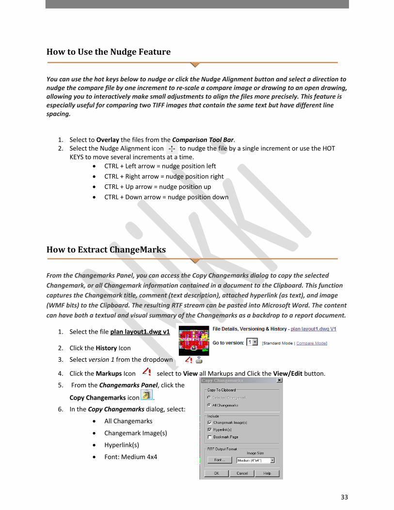
You can use the hot keys below to nudge or click the Nudge Alignment button and select a direction to nudge the compare file by one increment to re-scale a compare image or drawing to an open drawing, allowing you to interactively make small adjustments to align the files more precisely. This feature is especially useful for comparing two TIFF images that contain the same text but have different line spacing.
1. Select to Overlay the files from the Comparison Tool Bar. 2. Select the Nudge Alignment icon to nudge the file by a single increment or use the HOT
KEYS to move several increments at a time. • CTRL + Left arrow = nudge position left
• CTRL + Right arrow = nudge position right
• CTRL + Up arrow = nudge position up
• CTRL + Down arrow = nudge position down
How to Extract ChangeMarks
From the Changemarks Panel, you can access the Copy Changemarks dialog to copy the selected Changemark, or all Changemark information contained in a document to the Clipboard. This function captures the Changemark title, comment (text description), attached hyperlink (as text), and image (WMF bits) to the Clipboard. The resulting RTF stream can be pasted into Microsoft Word. The content can have both a textual and visual summary of the Changemarks as a backdrop to a report document.
1. Select the file plan layout1.dwg v1
2. Click the History Icon
3. Select version 1 from the dropdown
4. Click the Markups Icon select to View all Markups and Click the View/Edit button.
5. From the Changemarks Panel, click the
Copy Changemarks icon .
6. In the Copy Changemarks dialog, select:
• All Changemarks
• Changemark Image(s)
• Hyperlink(s)
• Font: Medium 4x4

34
7. Click Ok
8. The captured information is now ready to be
pasted into Microsoft Word. Open a blank
document and select Paste from the right
mouse button menu. Below is an example
of the end result.
How to Add a Image Stamp
Use this markup tool to insert external raster images (JPG or PNG) into your current markup layer. Once selected, images can be resized and positioned where you want them. The feature will retain a default location of your image stamp and retain the last 10 images used.
1. Download from the main training folder the file final.jpg and save to your desktop. 2. Navigate to your folder/project and select the plan layout1.dwg v2 from the folder view.
3. Select
4. Select the Image icon
• Upon selection one of two actions may take place:
i. If you have configured your profile with an image file (.png, .jpg) located on your PC ProjectDox will show this image file as a default in the grey bar (final.png) in Fig 4.3.

35
ii. If the profile has not been configured a browser window will display that will allow the end-user to navigate their PC or a shared drive on the network to select an image file to be used.
Fig.4.3
5. Browse to the desktop and select the final.png file and Click Open from the Select Raster file dialog.
6. Place the raster image on the bottom left of the drawing as seen in Fig.4.4. You can set the raster image by one of the following methods:
• Left-click and hold in the ProjectDox Viewer window to set the first corner point of the image, drag the mouse to where you want to set the second point, and release.
• Left-click on a point in the document where you want to center the raster image. The image is inserted into the document matching your orientation and is calculated to its natural size, relative to the document or drawing size.
Fig.4.4

36
7. Save the markup by selecting Markup Save icon and adding “your department name” and APP (BLD APP).
We have done an exercise publishing to PDF now let’s publish this current file with its new “Approval” markup using CSF. CSF stands for Content Sealed Format and allows the publisher to control attributes of the file/document to whom the file/document will be sent.
8. Select Publish from the Main Menu Toolbar and choose to Publish to CSF.
9. In the dialog choose Never under the Expire section 10. Click the Publish button. 11. Select to Save to File to a desired location.
To review this .csf file (content sealed format) will require the installation of the free ProjectDox Reader software found at http://www.ProjectDoxviewer.com/downloadreader.htm or it can be uploaded into ProjectDox and viewed.
How to create a Stamp Template
A Stamp Template can be a single or group of markup entities created as a Stamp that can be applied to plans or documents by users if granted permission by the System Administrator. The Stamp Template can include image files, signature files, and dynamic tokens to achieve the desired result. In this exercise we will create a Stamp Template to be used in the final approval of a set of plans.

37
See the Administrator Manuals for more information on recommendations for creating Stamps and Stamp Templates.
1. Open a file/document to use as a reference for size, shape and placement of the stamp. 2. Plan layout1.dwg
3. Click the Markup Icon Stamp Templates New
4. Select the image icon and choose an image file (FinalApproval.png)
• Recommend background of the image file be transparent 5. Drag the image file to the upper right corner as seen below.
6. Using the Zoom Window zoom in on the image file 7. Select the Text Box tool and add two tokens to the
image file to create a dynamic stamp template.
• %ProjectName
• %Date

38
8. Click the Markup Icon Stamp Templates Save As “FinalApproval”
ProjectDox does not recalculate the stamp based on the size of the file. A 2X2 stamp on the stamp template will appear the same on a 24X36 as it would an 8 ½ X 11.
Stamp Template application done by the Batch Stamp process will calculate the position indicate by the template and stamp based on the size of the file. For example, in our template we have placed the stamp in white space between the drawing and the edge of the file. When applied using the batch stamp process this stamp will be applied to the far right corner. If we want to maintain the position in the Stamp Template we must add an Offset to our Stamp Template. An offset or registration mark can assist in maintaining our desired position. The offset is a tiny mark applied. When the template is processed ProjectDox reads the offset as the beginning of the stamp and will place that mark at the far upper right corner allowing the actual stamp to retain its position.
How to Edit a Stamp Template
1. Click the Markup Icon Stamp Templates Open 2. Select “Final Approval”
• The stamp will display in the upper right based on our template 3. Zoom into the stamp area and place a registration mark in the bottom right corner.
• Greater the Zoom the less the offset will be seen when the plan is printed 4. Click the Markup Icon and Save the changes.

39
Example: No registration mark.
Example: Includes registration mark.
40
How to Add a Markup Stamp
The ability to add a dynamic stamp and/or stamp template to a document is granted by a System Administrator. If provided this permission the Stamp Icon is enabled in the Markup Toolbar when at least one Stamp Template exists.
1. Select the Markup Stamp icon 2. Select the Stamp Template to apply by clicking the name.
a. Stamping permissions gives a user access to create and use any Stamp Templates in the site.
3. Drag the cursor onto the file to the desired location. 4. Left Click and drag the stamp template into place on the file.
The stamp template is treated as a group of elements and are resized and moved as a single entity.
How to Create a Batch Stamp Template
If granted by an Administrator (users with Stamping permission have access to Stamp Templates and Batch Stamp Templates) users will have access to create and use Batch Stamp Templates. Batch Stamp Templates create a standard format for applying stamps to documents and plans. For more information on Batch Stamp Templates see the Administrator and/or User Training Guides.
In this exercise we will create a Batch Stamp Template and use our previously created Final Approval Stamp Template to apply to the plans and/or documents.
1. Select a file and click the Batch Stamp Icon to enable the Batch Stamp Feature from within a project.
a. System Administrators can configure Batch Stamp Templates from the AdminBatch Stamp Templates area.
2. Select the Advanced tab from the Batch Stamp Dialog a. Type a Template Name: Instructor Example b. Select the Output Type = PDF c. Type the name of the destination folder or place a checkmark next to the name in
the folder tree displayed = Approved Plans and Documents. d. Burn in Markups = YES e. Where to place Stamp = Bottom Right f. Pages to Stamp = First g. Select Stamp = FinalApproval

41
h. Select the Save Template button.
Templates create consistency in the stamping process and allow future users to use the Basic Tab to select the Batch Stamp Template and Process the selected files making the process efficient and quick.
How to Use the Redaction Tool
Let’s create another markup on the plan layout1.dwg file using the Blockout for Redaction tool. In this exercise we want to blockout from view the address of the Cisco building. The ProjectDox Viewer software allows users to designate a markup file containing blockout entities (rectangular solid covers) to be published to a document (as CSF, PDF, or TIFF) as a "redaction". This means that the blockout entities associated with the published document can never be edited or removed by the end-user and the text and images beneath the blockout cannot be viewed, copied, or searched. The blockout entities are used to conceal sensitive information for legal, financial, and security reasons, for example.
The Blockout for redaction markup entity allows you to place a rectangular cover over an area of a sensitive or confidential document to block only certain portions from being viewed, searched, or copied. To complete the redaction, the file must be published to CSF, PDF, or TIFF format. If the file being marked up is a CSF file, it must have the markup authoring and burn-in rights enabled and cannot already have a redaction markup burned in.
1. Open plan layout1.dwg
2. Select to display the Redaction Toolbar to the left of the viewing area
file
3. Select the Redact Area icon(first icon) 4. Navigate to the bottom right of the plan layout1.dwg file (can also use Search tool to Search for
“Cisco Systems”). 5. Hold the left mouse button down and highlight the text “ 3750 Zanker Rd” 6. In the Tool Properties Toolbar enter the Reason for the redaction as “Sensitive Information”.
a. Adding a reason will allow for a report to be provided of the redactions and their reasons.
7. Select the Markup Save Icon to save the changes.
Important note: The Redact Area feature only blocks information when its markup file has been published to a CSF or PDF file. If the markup with the blockout entities is saved and reloaded, areas covered by the blockout entity can be seen, searched, and copied. Also note that redaction capabilities physically remove text and blanks out raster image information. Vector information and associated
42
block attributes are not removed from the file. Vector information under the redaction blockouts is covered, however, and is not visible in the published file
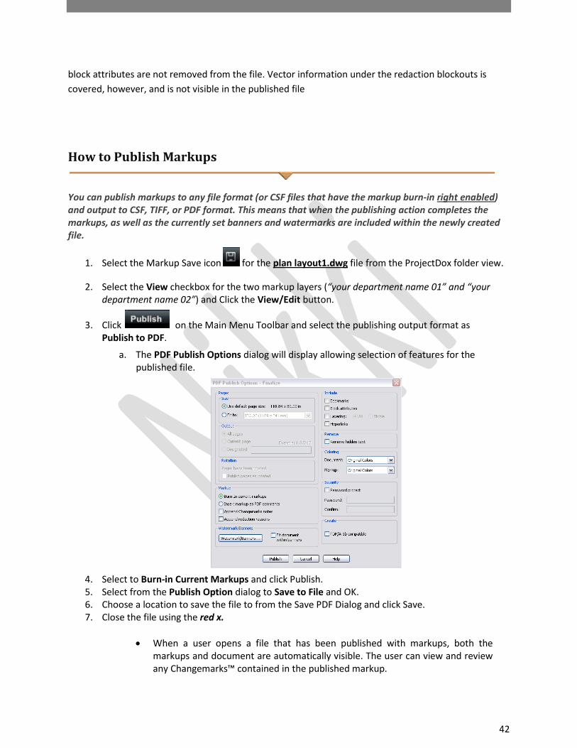
How to Publish Markups
You can publish markups to any file format (or CSF files that have the markup burn-in right enabled) and output to CSF, TIFF, or PDF format. This means that when the publishing action completes the markups, as well as the currently set banners and watermarks are included within the newly created file.
1. Select the Markup Save icon for the plan layout1.dwg file from the ProjectDox folder view.
2. Select the View checkbox for the two markup layers (“your department name 01” and “your department name 02”) and Click the View/Edit button.
3. Click on the Main Menu Toolbar and select the publishing output format as Publish to PDF.
a. The PDF Publish Options dialog will display allowing selection of features for the published file.
4. Select to Burn-in Current Markups and click Publish. 5. Select from the Publish Option dialog to Save to File and OK. 6. Choose a location to save the file to from the Save PDF Dialog and click Save. 7. Close the file using the red x.
• When a user opens a file that has been published with markups, both the
markups and document are automatically visible. The user can view and review any Changemarks™ contained in the published markup.

43
• If the editable markup contains blockout for redaction entities, the markup is
automatically published with redacted entities.
8. Review the file on the desktop to see the markups and the redaction. The results should be similar to the below.
How to use Redact to Phrase List & Redact by Phrase
In addition to the Blockout for Redaction feature there are two other features; Redact to Phrase List and Redact by Phrase. The next two exercises will give you experience with these features.
44
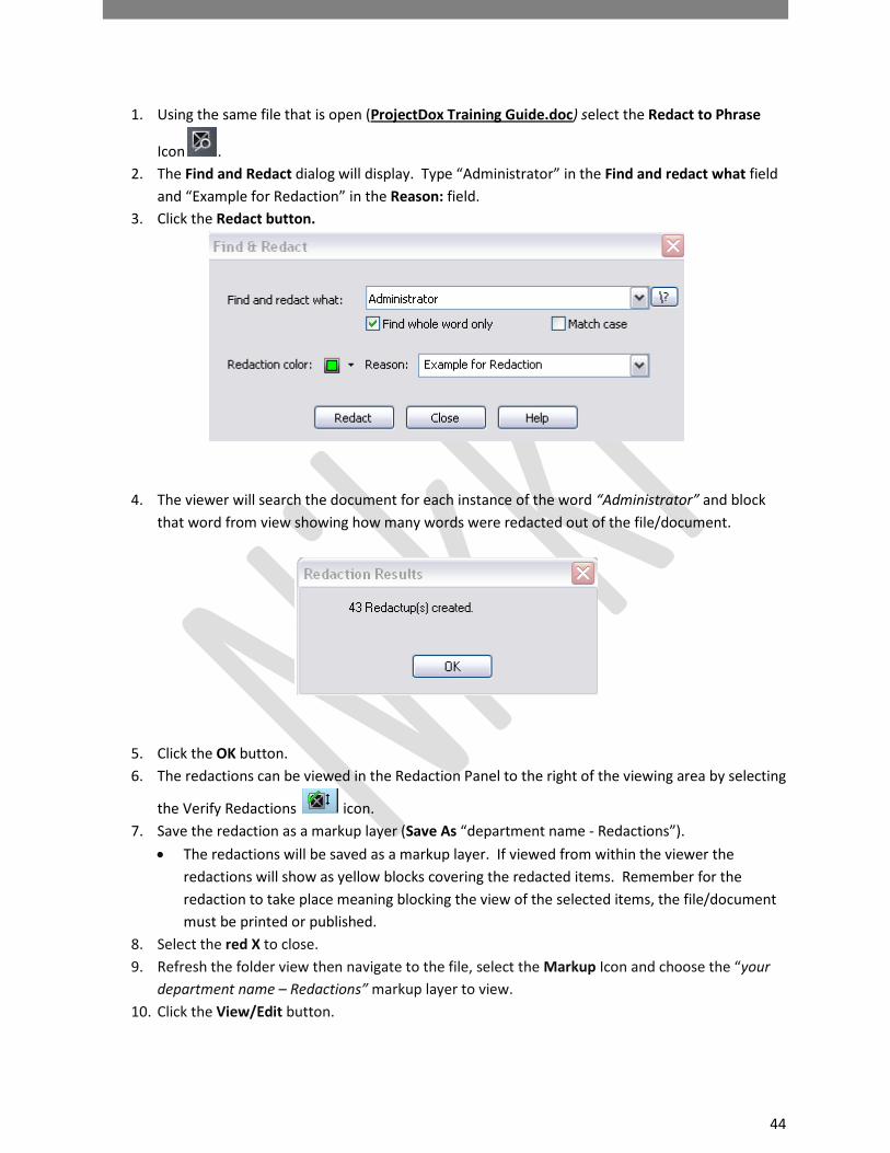
1. Using the same file that is open (ProjectDox Training Guide.doc) select the Redact to Phrase
Icon . 2. The Find and Redact dialog will display. Type “Administrator” in the Find and redact what field
and “Example for Redaction” in the Reason: field. 3. Click the Redact button.
4. The viewer will search the document for each instance of the word “Administrator” and block that word from view showing how many words were redacted out of the file/document.
5. Click the OK button. 6. The redactions can be viewed in the Redaction Panel to the right of the viewing area by selecting
the Verify Redactions icon. 7. Save the redaction as a markup layer (Save As “department name - Redactions”).
• The redactions will be saved as a markup layer. If viewed from within the viewer the redactions will show as yellow blocks covering the redacted items. Remember for the redaction to take place meaning blocking the view of the selected items, the file/document must be printed or published.
8. Select the red X to close. 9. Refresh the folder view then navigate to the file, select the Markup Icon and choose the “your
department name – Redactions” markup layer to view. 10. Click the View/Edit button.
45
11. Notice the highlighted boxes throughout the document. You can also Publish the document to a PDF to see the redactions take effect.
How to Print a File
To print the open image with the default printer settings, click (hotkey + < P>). Print. If allowed by your administrator, you can access the Print menu. The Print dialog box contains standard print options, such as choosing a printer, giving a range of pages to print, etc. You can also select to print to scale options, view Print Preview, and set Banner and Watermark options. An option is available to print Changemarks information and/or redaction reasons as an appended page.
1. If Print Region is selected from the Print menu, press the mouse on a starting point of the viewer and draw a rectangle on the area of the document that you would like to print. The
Print dialog appears when you release the mouse. Click on the toolbar and select Print from the submenu. The application will pull in your systems default printer.
2. Select the Print Changemark Information checkbox
3. Select the Automatically Rotate for Best Fit checkbox if you want ProjectDox to determine if rotating the image by 90 degrees will allow more of the image to fit on the printed page.
1. Some older printers, and the PDF Distiller and Writer, may not properly invert print outs and many file types print reversed (black background and white foreground). To correct the print out (white background with black foreground); enable the Optimize for PDF/PostScript Printing option in the Print Options dialog. When selected, this causes a bitmap of the current image to be sent to the printer resulting in accurate print outs for the problematic printer or print driver. Note that enabling this option results in a slower print time and a larger print spool file. This option is persisted per printer.
4. Observe the Print Preview area of the Print dialog to verify the area you wish to print is contained in the printable area of the page (indicated by the dashed blue line).
• If the print preview image does not display what you expect, study the textual output in the print preview panel. It displays the image's dimensions, the current scaling (e.g. "Fit to page," "1/50," etc.), the scaled output size (the image's dimensions multiplied by the scaling), the paper size dimensions, and the printable area size. Pay particular attention to the scaled output size compared to the printable area size; these are depicted, respectively, as the red and blue dashed lines in the preview image. Adjust the paper size (Printer Setup button) or scaling (Scale tab) as necessary to obtain the desired output.
11. Click Print to print the file if your computer has access to a printer.

46
How to Add and Edit Watermarks/Banners
You can add, edit, or clear print banners or the watermark if they have not already been defined by the ProjectDox Administrator. ISO banners are strings of specific information (date, time, page number, user name, etc.) assigned to a location on the document header and footer. Watermark are a semi transparent character string that stretches from the lower left corner to the upper right corner of the printed or on screen document. These settings are useful for displaying a document's classification to the viewer (e.g., proprietary, draft, etc.). In this exercise, we will add both an ISO banner and watermark to the plan layout1.dwg file.
1. Click on the toolbar and select ISO Banners/Watermarks (the button is also available from the Print Dialog).
2. Click to expand Watermark 3. Click on <blank> located below the WaterMark heading and type “DRAFT” into the space.
• Click the Font button to change the font by selecting a font name, Style and size from the Font dialog box. Note: Any change in font style and name selection will be applied to all defined watermark and banner settings for the current document (you cannot define multiple fonts or styles per document). The Watermark font size is not affected by your font size selection. The Screen Banner is not affected by any Font setting.
4. Click Ok
5. Select the Print Icon 6. Notice the Print Preview Area
7. Click the Banner/Watermarks button
8. Expand the Screen Watermark and type “DRAFT II” over the <blank> area.
• These settings are useful for displaying a document's classification to the viewer (e.g., proprietary, draft, etc.) and the values can differ from the values entered in the Watermark and banner location lines.
• The On screen banner fonts are not affected by choices made in the Font dialog box.
9. Click the Ok button.
10. The screen now shows “DRAFT II” and the printable document displays “DRAFT”. You may need to move the dialog box to the side to see the watermark.
11. Click the Banners/Watermarks button
12. Select the Screen Banner and type %Date.
• Entering % into the field will result in a list of system tags that can be used to display information in the banner, watermark, etc.
13. Click Apply and note the banner added to the file in the ProjectDox viewer.
14. Click Top Left and type %Date, %Login, and %TotalPages into three separate fields under this heading.

47
15. Click Ok.
16. Select the Print Icon and Click the Print button if your computer has access to a printer or you can look in the Print Preview in the upper left of the page and can see text in the corner.
17. The result is seen on the printed file below (Fig.6) in a banner on the top left where the variables are substituted with values from the system.
Fig.6

48
Toolbars
This guide provides a quick overview of all of the button functions available in the ProjectDox Visualization 7.0 SR1 viewer application.
Main Toolbar
This toolbar, located in the upper left corner of ProjectDox Visualization, contains icons for executing markup commands, saving markups, printing pages and regions, and object selection.
Markup. Access commands regarding markup files, such as creating a new markup file, opening a markup file for edit or review, saving a markup file, consolidate markups, as well as accessing a stamp template submenu.
Markup Save – Available when a markup is open for edit, use this button as a quick way to save the current markup file to the markup directory.
Print. If allowed by your administrator, you can access the Print menu. The Print dialog box contains standard print options, such as choosing a printer, giving a range of pages to print, etc. You can also select to print to scale options, view Print Preview, and set Banner and Watermark options. An option is available to print Changemarks information and/or redaction reasons as an appended page.
If Print Region is selected from the Print menu, press the mouse on a starting point of the viewer and draw a rectangle on the area of the document that you would like to print. The Print dialog appears when you release the mouse.
Select. Use the Select tool to select text in a document to copy (if allowed), select an intelligent object, and to activate Changemarks.
Find. You can search the text on documents and images with the search tool. Wildcards, macros, and regex search strings are accepted. You can search up, down, find whole word, match case, and turn on term-hit highlighting.
ProjectDox Visualization Enterprise Functions Menu

49
Markup Toolbar The Markup toolbar contains tools for adding markup entities and Changemarks (annotations) to the current file. The Markup toolbar is displayed on the left side of the viewer when you:
• Click from the functions toolbar.
• Click and select New.
Additional markup tools are available by clicking on any arrow that exists to the right of the currently displayed tool. Please see the Tool Properties Toolbar section of this document for available tool options.
Edit Markups. Use to select and edit markup attributes, resize, reshape, rotate, copy, or move entity.
Arrow Pointer. Use to add arrows to your images. The arrow head is set at the first selection point.
Text. Use the Text tool to insert text directly on the image (rather than in a note). Use the Markup Properties tools to change the font name, size, etc.
Changemarks. The Changemarks tool allows markup authors to type or copy/paste in detailed text in a scrolling window. Authors can also add hyperlinks to point the user to additional information. Reviewers simply need
to double-click on the markup entity while in select mode to review the text, or automatically scroll through each Changemarks contained in the Changemarks list by clicking a Next button. See Also "Changemarks Panel".
Changemarks combination tools: These tools are available purely for convenience. With one single click, you can add a Changemarks with either a
Highlight , Text Highlight , Cloud , or Arrow . Once added, the two entities behave totally independent of each other. The Text Highlight is only enabled when text found on the file or document.
Insert Image. Use this markup tool to insert external raster images (JPG, BMP, or PNG) into your current markup layer. Once selected, images can be resized and positioned where you want them.

50
You can set multiple instances of this same image entity or use the Browse button in the Markup Properties bar to choose another raster image to insert. The properties bar also contains a list of 10 most recently used images which can be individually selected and inserted.
Add Markup Stamp. If Stamp Templates have been authored and saved and your administrators have allowed access, the markup stamp button is available on the Markup Toolbar. When clicked, a list of available markup stamps is shown that can be added to the current markup layer.
The stamp template is a group of markup entities that have been defined as a single unit and all elements of the template are resized and moved as a single entity and cannot be edited otherwise. Color, content, and other elements are defined by the author when a stamp template is created and saved.
When a stamp is inserted, if a dynamic text field exists (such as %Page, %Date, %dbstring(value), etc.), the field is resolved and results are populated in the stamp.
Cloud and Polyclouds. Add cloud or polycloud shapes on your images.
Highlight. Creates highlight entities by drawing a rectangle. Unlike the filled shape entity, highlights do not have the option of being filled or hollow.
Sketch and PolySketch. Use this tool to draw freehand shapes and lines on your image. Polysketch can be filled or unfilled.
Crossout, Scratchout, Arc, and Line Tools. Use any of these tools to add linear shapes on your documents and images. The mouse cursor will change to reflect the tool selected. Line width and style can be selected in the markup properties toolbar, with additional arrow end styles available for the Line Arrow tool.
Rectangle, Rounded Rectangle, Ellipse, and Polygon shapes. Shapes can be used as highlights or hides, and can be filled or hollow as determined by your selection in the Shape Properties drop-down list. Use the Hides shapes to cover or “hide” areas of the image. Hides shapes are automatically the same color as the background color. The mouse cursor will change to reflect the tool selected.
Edit Text. You can highlight, strikeout, strikethrough, and underline selectable text contained in a drawing or document. Simply drag a box around the text area you want to include to select and mark it.
51
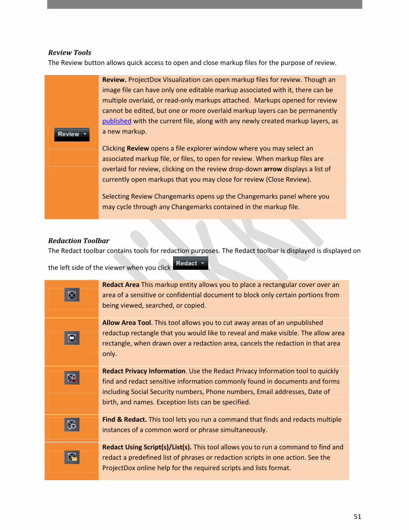
Review Tools The Review button allows quick access to open and close markup files for the purpose of review.
Review. ProjectDox Visualization can open markup files for review. Though an image file can have only one editable markup associated with it, there can be multiple overlaid, or read-only markups attached. Markups opened for review cannot be edited, but one or more overlaid markup layers can be permanently published with the current file, along with any newly created markup layers, as a new markup.
Clicking Review opens a file explorer window where you may select an associated markup file, or files, to open for review. When markup files are overlaid for review, clicking on the review drop-down arrow displays a list of currently open markups that you may close for review (Close Review).
Selecting Review Changemarks opens up the Changemarks panel where you may cycle through any Changemarks contained in the markup file.
Redaction Toolbar The Redact toolbar contains tools for redaction purposes. The Redact toolbar is displayed is displayed on
the left side of the viewer when you click .
Redact Area This markup entity allows you to place a rectangular cover over an area of a sensitive or confidential document to block only certain portions from being viewed, searched, or copied.
Allow Area Tool. This tool allows you to cut away areas of an unpublished redactup rectangle that you would like to reveal and make visible. The allow area rectangle, when drawn over a redaction area, cancels the redaction in that area only.
Redact Privacy Information. Use the Redact Privacy Information tool to quickly find and redact sensitive information commonly found in documents and forms including Social Security numbers, Phone numbers, Email addresses, Date of birth, and names. Exception lists can be specified.
Find & Redact. This tool lets you run a command that finds and redacts multiple instances of a common word or phrase simultaneously.
Redact Using Script(s)/List(s). This tool allows you to run a command to find and redact a predefined list of phrases or redaction scripts in one action. See the ProjectDox online help for the required scripts and lists format.
52
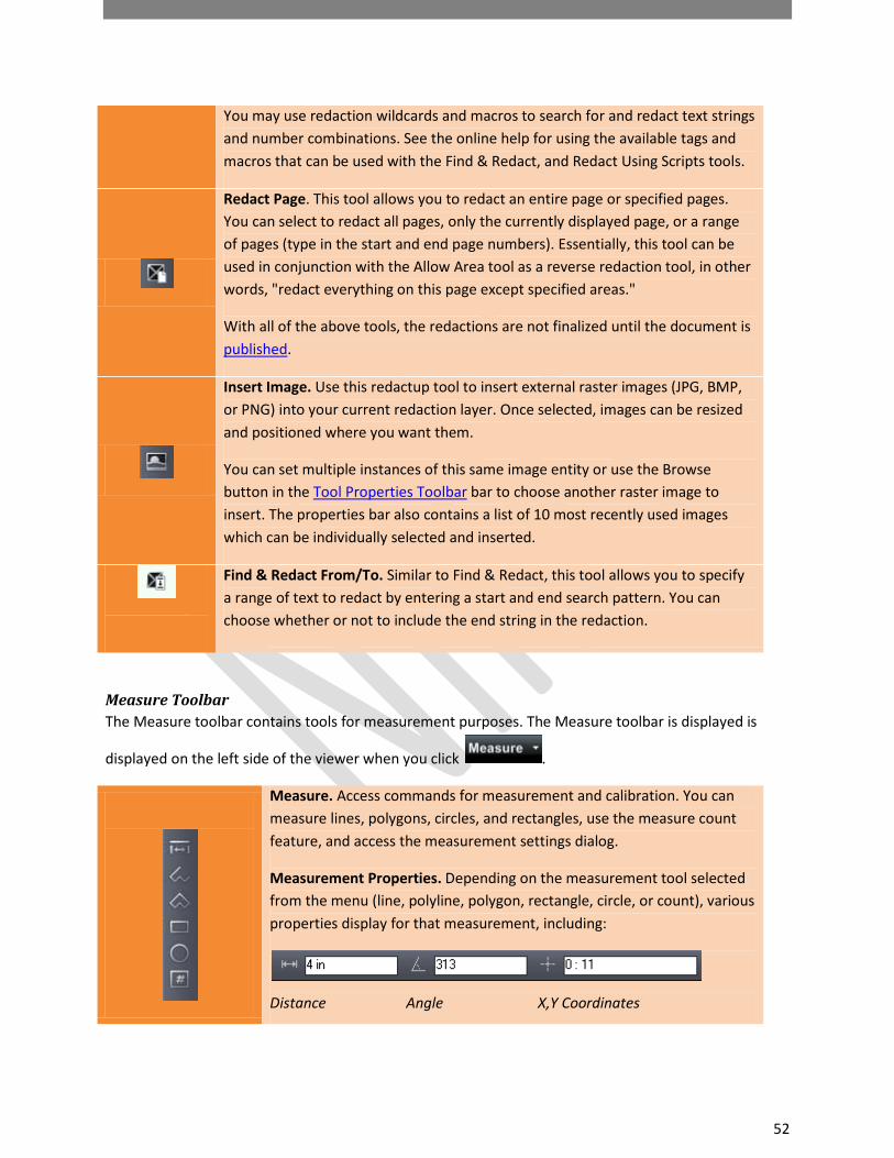
You may use redaction wildcards and macros to search for and redact text strings and number combinations. See the online help for using the available tags and macros that can be used with the Find & Redact, and Redact Using Scripts tools.
Redact Page. This tool allows you to redact an entire page or specified pages. You can select to redact all pages, only the currently displayed page, or a range of pages (type in the start and end page numbers). Essentially, this tool can be used in conjunction with the Allow Area tool as a reverse redaction tool, in other words, "redact everything on this page except specified areas."
With all of the above tools, the redactions are not finalized until the document is published.
Insert Image. Use this redactup tool to insert external raster images (JPG, BMP, or PNG) into your current redaction layer. Once selected, images can be resized and positioned where you want them.
You can set multiple instances of this same image entity or use the Browse button in the Tool Properties Toolbar bar to choose another raster image to insert. The properties bar also contains a list of 10 most recently used images which can be individually selected and inserted.
Find & Redact From/To. Similar to Find & Redact, this tool allows you to specify a range of text to redact by entering a start and end search pattern. You can choose whether or not to include the end string in the redaction.
Measure Toolbar The Measure toolbar contains tools for measurement purposes. The Measure toolbar is displayed is
displayed on the left side of the viewer when you click .
Measure. Access commands for measurement and calibration. You can measure lines, polygons, circles, and rectangles, use the measure count feature, and access the measurement settings dialog.
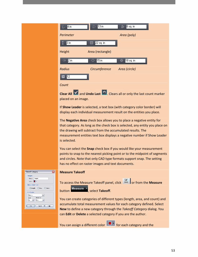
Measurement Properties. Depending on the measurement tool selected from the menu (line, polyline, polygon, rectangle, circle, or count), various properties display for that measurement, including:
Distance Angle X,Y Coordinates
53
Perimeter Area (poly)
Height Area (rectangle)
Radius Circumference Area (circle)
Count
Clear All and Undo Last . Clears all or only the last count marker placed on an image.
If Show Leader is selected, a text box (with category color border) will display each individual measurement result on the entities you place.
The Negative Area check box allows you to place a negative entity for that category. As long as the check box is selected, any entity you place on the drawing will subtract from the accumulated results. The measurement entities text box displays a negative number if Show Leader is selected.
You can select the Snap check box if you would like your measurement points to snap to the nearest picking point or to the midpoint of segments and circles. Note that only CAD type formats support snap. The setting has no effect on raster images and text documents.
Measure Takeoff
To access the Measure Takeoff panel, click or from the Measure
button , select Takeoff.
You can create categories of different types (length, area, and count) and accumulate total measurement values for each category defined. Select New to define a new category through the Takeoff Category dialog. You can Edit or Delete a selected category if you are the author.
You can assign a different color for each category and the

54
measurements placed on the document will display with that color.
The list of categories can be sorted by name (click Category in the top column). Click the ascending/descending arrow to arrange the list accordingly.
Once the categories are defined, highlight a category and use the available (dependent on type) measurement tools to place multiple measurements on the document. As you place each measurement entity, accumulated totals display at the top of the takeoff panel.
Takeoff information can be Exported to a file or to the Clipboard through the Takeoff Export dialog.
To hide a category, click the hide icon to toggle between visible and
hide. To toggle all categories from visible/hide state, click the icon located in the column heading. Hidden category information will still remain available for export.
Category and takeoff information is saved as a markup layer to the current file and can be reviewed as any other markup file.
Publish Tools The Publish toolbar contains tools for republishing documents. The Publish options menu is displayed
when you click .
Save and Publish
Select Save Current View as JPG from the submenu to save the current view displayed in the ProjectDox viewing window as a JPG file. This feature captures the image window as a screen capture and will include all visible elements (e.g., markup entities, magnifier window, measurement indications, etc.). Note that redactions are NOT finalized in the captured image.
Select Publish to CSF from the submenu to publish the current file to secure CSF format with encrypted Visual Rights. CSF is a neutral 2D format that is a replica of the source file, including images, graphics, layout, and more. Secure CSF files published with ProjectDox Desktop can be opened in the free ProjectDox Reader.
Select Publish to PDF, or TIFF from the submenu to publish the current file (with any open markups) to PDF, or TIFF format. A variety of publishing options can be

55
selected from the dialog.
When redactup entities are present in the open markup, publishing to CSF, PDF, or TIFF finalizes the redaction in the output file.
ProjectDox Viewer Display Toolbar
The ProjectDox Viewer display toolbar contains tools to control how images display.
Color. Use this button to change the background color of file types with "transparent" background colors, such as monochrome raster and vector file types (color raster files are not affected) to black, white, or gray.
Monochrome: Available from the color menu is also the Monochrome setting. Turning on Monochrome change all lines of a color vector image to a single color (the default is black) while leaving markup entities in color for quick identification.
Set Visible Layers. Turn image layers (e.g., layers of a DWG file) on or off to minimize clutter in the view window or to focus on a particular area or part.
Rotate. The Rotate button allows you to rotate the image in 90 degree clockwise increments.
Fit All. Returns the zoom level to 100% so the full image displays in the ProjectDox window.
Fit Width. Ideal for 8.5” X 11” office documents, Zoom Width changes the zoom level so that the entire width of the image appears in the window. You can read rows of text without having to scroll right and left to see the entire line.
Zoom Slider. You can move the slider ball from left to right to increase or decrease magnification. Move left to decrease, right to increase. The ball snaps back to center on release.

56
Pan/Zoom. When zoomed in on an image, use the Pan tool to maneuver around the image.
Magnifier. Use the Magnifier to summon a magnified view window on your image. The magnification can be adjusted and a toggle tool is
available to allow you to switch between eye glass , bird’s eye
, and docking behavior.
Page Control. Use page control to navigate through the pages of your documents. You can select a specific page from the drop-down list.
CSF Icon – this icon displays when viewing secure CSF format documents. Clicking on the icon launches a dialog that shows you what Visual Rights were applied to the published file.

57
ProjectDox Compare Toolbar
Overlay: Use this button to overlay both versions on top of each other. Both files display at their original colors. Use the slider to change the transparency of each file - left to dim the compare version, right to dim the open version.
Overlay Differences: With this button, the compare file version opens overlaid on the open file. The open file displays in red (deleted geometry), and the compare file displays in green (added geometry). Geometry that has not changed (common between both revisions) is gray.
Side-By-Side: Both versions are displayed in a split-screen image. Move the slider to view transparent differences overlaid in each version.
Text Comparison: While a graphical comparison is useful for viewing differences in CAD drawings (as overlaid images), this method has limitations when it comes to comparing the actual text contained in a document file. Use the Text Comparison mode to view the (non WYSIWIG) text content comparison of the open and compare documents.
The document is shown in split screen mode with the open and compare files displayed in two windows as lines of text, and the WYSIWIG view of the Compare or Open file shown beneath. Text differences between the two documents are highlighted in yellow, red, or green.
Red indicates something that was deleted out of the open document. Green indicates something that was added to the compare document. Yellow indicates something that has changed between the two documents. A merged report can be exported to PDF using the Text Compare Report button.
Open File (Only): Only the file that was first opened is displayed (normal colors). The set alignment points for comparison tool is available in this mode. All Annotate, Review, Redact, Measure, and Publish features are supported in this compare mode only.
Compare File (Only): Only the file that was opened for compare is displayed (normal colors). The set alignment points for comparison tool is available in this mode. Measure, and Publish features are supported in this compare mode.

58
Additions: Only added areas (areas present in the compare version, but not in the open version) are displayed in green.
Deletions: Only deleted areas (areas present in the open version, but not in the compare version) are displayed in red.
Unchanged: Only areas that are present in both the compare version and open version are displayed in gray.
Transparency Slider: This tool is available for Overlay, Overlay Differences, and Side-by-side modes to adjust the transparency amount of the two documents. In the two overlay modes, move the slider to the left to reduce the transparency of the Compare document (additions), move the slider to the right to reduce the transparency of the Open document (deletions).
When the slider is centered, both documents display at 50% transparency.
In Side-by-side mode, center the slider to view the changes side by side, overlaid at 25% transparency. Move the slider all the way to the left to view 50% transparency, or all the way to the right for 0% transparency (no overlay).
Text Compare Report: Use this button to generate a merged text compare report and output the results to PDF.
Set Alignment Tools
Nudge Alignment: This button is available when using the Overlay, Overlay Differences, Side by Side, Additions, Deletions, and Unchanged viewing modes. You can use the Nudge Alignment commands to nudge and re-scale a compare image or drawing to an open drawing, allowing you to interactively make small adjustments to align the files more precisely. This feature is especially useful for comparing two TIFF images that contain the same text but have different line spacing. Click the Nudge Alignment button and select a direction to nudge the compare file by one increment.
Set/Clear Alignment Points. The Set Alignment Points tool allows you to compare two versions of a file that are of different scales, or world page sizes. Use the tool to select two points on each version that define a single identical location that is used as a common alignment section when the two files are overlaid. Clear alignment clears any currently set points.

59
Tool Properties Toolbar
This toolbar contains tools to modify the properties of Markups and Measurements. The properties bar is located directly below the main toolbar.
ProjectDox Visualization Help. Launch the on-line Help file to access detailed information about using ProjectDox Visualization features.
Text Properties. Use the Bold, Italic, and Underline buttons to modify the style of your markup text.
Use the font style and size drop-down boxes to change the markup font style and size used. Changing the size of the markup text box on the image will dynamically update the size of the font used in the font size selection box.
MarkupText Background. Use this feature to select a background type for your markup text box. Available choices from the drop-down menu are Transparent, Match Display Background, and <Color>. Use Select Background Color to choose the markup text background color from the Color Chooser dialog.
Tokens. Available when creating a stamp template, use this button to replace markup text with token variables. The token expressions will be resolved when a user inserts or double clicks on a stamp containing token variables. If the token used is a %prompt(), the user will be prompted with a text entry field where he can type in the requested information.

60
Line Width. Change the width of markup lines using the Line Width tool.
Line Style. Choose the style of line used for any of the Sketch, arrow, shape, edit text, or line tools. Choices include solid, dotted, dashed, or dash-dot.
Shape Properties – Fill Type. Select Solid, Hollow, Highlight, or Background Fill as attributes for a Rectangle, Ellipse, or Polygon shape. Choosing solid or highlight fills the shapes with the currently selected markup color.
Arrow End Styles. Choose the start and end arrow styles to use with the Line Arrow tool.
Color. Change the color of any markup entity using the 16 predefined markup colors, or you can choose More… to use the custom Color Chooser dialog.
Copy Markups. Use this button to copy selected markup entities to one or all pages of the document (specific page numbers can be entered in the Copy Entities to Designated Pages dialog). Entities that cannot be copied include Edit Text

61
entities, Changemarks, and Redactups.
Hyperlink. Add a hyperlink to any markup entity when this icon is available. Hyperlinks can be launched by clicking on a markup entity containing a hyperlink
with the Select tool .
ProjectDox Viewer Task Pane
The task pane can be toggled open and closed by clicking on the Pane Arrow on the right side of the ProjectDox Viewing window.
Pane Arrow. This icon, located on the right side of the viewing window, expands and collapses the tabbed tool panel when clicked.
Page Thumbnails Panel The Page Thumbnails Tab opens a scrollable thumbnail navigation panel on the right side of the ProjectDox viewing area. When clicked, the pages of the currently opened file appear in the panel as small click-able thumbnail images. First/Previous/Next/Last buttons are provided for quick page navigation.
If a markup file is open, an exclamation point appears to indicate the pages that contain markups. You can use the next/previous markup page arrows to navigate through only those pages containing markups.
Bookmarks Panel The bookmark panel lists the internal bookmarks contained in the document being viewed. In this panel you can expand or collapse the bookmark trees by clicking the +/- signs. Click a bookmark to go to

62
that location in the document. Use the search field to search for bookmark titles. Use the next and previous arrows to navigate through bookmarks
Changemarks Panel (See Changemarks from the Markup Toolbar)
Next and Previous arrows are provided to navigate through the Changemarks list. The list can be sorted by the categories provided in
the Sort drop down list
The Changemarks list window also contains buttons to search the content, title, or author information of a Changemarks.
Use the Show All button to undo any filters applied and show all Changemarks contained in the document.
Use the Extract Changemarks button to copy the selected Changemarks, or all Changemarks information contained in a document to the Clipboard. This function captures the Changemarks title, comment (text description), attached hyperlink (as text), and image (WMF bits) to the Clipboard. The resulting RTF stream can be pasted into Microsoft Word.
Verify Redactions Panel
Once you have redacted a document (see Redaction tools) you

63
can optionally run the Verify tool to manually check and adjust the accuracy of each redacted area that has been set on the document
before you finalize the redaction through publishing .
Measure Takeoff Panel
To access the Measure Takeoff panel click this tab, or from the
Measure button , select Takeoff.
The takeoff panel lets you create categories and accumulate measurements and export the information to a (markup) file or to the Clipboard. You can total length, area, and counts by placing multiple measurement entities on the drawing for each category defined.

64
HOT KEYS Below is a list of short cut keys that allow for navigation or changes to be made in the viewer without
removing your fingers from the key board.
HOT KEYS Feature Key Board Control Feature Key Board Control
Help About <Ctrl> + <A> Save View as JPG <Ctrl> + <shift> + <J>
Toggle through Bookmarks
<Ctrl> + <B> Publish to CSF <Ctrl> + <shift> + <K>
Add a bookmark <Ctrl> + <Alt> + <B> Close Review <Ctrl> + <Shift> + <R>
Copy to Clipboard <Ctrl> + <C> Save as Markup <Ctrl> + <Shift> + <S>
All <Ctrl> + <E> Publish to TIFF <Ctrl> + <Shift> + <T>
Mirror (Flip) <Ctrl> + <F> Change mouse tool to zoom window
<Ctrl> + <Shift> + <X>
Print Region <Ctrl> + <G> Change mouse tool to magnifier
<Ctrl> + <Shift> + <Z>
Help Contents <Ctrl> + <H> Rotate 90 Degrees <Ctrl> + <Space>
Show Layers <Ctrl> + <L> Rotate 90 degrees counter-clockwise
<Ctrl> + <Shift> + <Space>
Open Markup <Ctrl> + <M> Find <F3>
New Markup <Ctrl> + <N> 1. Zoom In 2. Zoom Out
1. <+> 2. <->
Print <Ctrl> + <P> Move to Previous Page
<Page Up>
Save Markup <Ctrl> + <S> Moves to Next Page <Page Down>

65
HOT KEYS
Feature Key Board Control Feature Key Board Control
Thumbnail Panel <Ctrl> + <T> Go to First Page <Ctrl> + <Home>
Paste <Ctrl> + <V> Go To Last Page <Ctrl> + <End>
Fit Width <Ctrl> + <W> Next Markup Page <Ctrl> + <Page Down>
Delete <Ctrl> + <X> Previous Markup Page <Ctrl> + <Page Up>
Redo <Ctrl> + <Y> Last Page <End>
Undo <Ctrl> + <Z> First Page <Home>
Change mouse tool to pan
<Ctrl> + <Shift> + <A> The following hotkeys can be used while in Compare mode to nudge the overlaid "older version" in the desired direction
Burn in Markup <Ctrl> + <Shift> + <B> 1. Nudge Left 2. Nudge Right
1. <Ctrl> + <Left arrow> 2. <Ctrl> + <Right arrow>
Close Markup <Ctrl> + <Shift> + <C> 1. Nudge position up 2. Nudge position
down
1. <Ctrl> + <Up arrow> 2. <Ctrl> + <Down arrow>
Publish to PDF <Ctrl> + <shift> + <D> 1. Nudge scale up 2. Nudge scale down
1. <Ctrl> + <+> 2. <Ctrl>+<->

66