PROJECT SUBMITTAL REQUIREMENTSElectronic = e 1. “e” = No electronic file sent to the recipient....
79
PROJECT SUBMITTAL REQUIREMENTS 12-10-2019 REV 7 PART 1: DELIVERABLE SUBMITTAL REQUIREMENTS PART 2: CAD STANDARDS PART 3: ROOM NUMBER ASSIGNMENT STANDARDS PART 4: GIS STANDARDS APPENDICES APPENDIX A: CAD STANDARD MASTER LAYER LIST APPENDIX B: SPACE INVENTORY DRAWINGS APPENDIX C: CHANGE LOG Facilities Information Resources Facilities & Services University of Illinois at Urbana-Champaign 117 Physical Plant Service Building, MC-821 1501 South Oak Street Champaign, IL 61820 217-333-0923 [email protected] www.fs.illinois.edu/docs/default-source/FIR/project-submittal-requirements.pdf
Transcript of PROJECT SUBMITTAL REQUIREMENTSElectronic = e 1. “e” = No electronic file sent to the recipient....

PROJECT SUBMITTAL REQUIREMENTS 12-10-2019 REV 7
PART 1: DELIVERABLE SUBMITTAL REQUIREMENTS
PART 2: CAD STANDARDS
PART 3: ROOM NUMBER ASSIGNMENT STANDARDS
PART 4: GIS STANDARDS
APPENDICES
APPENDIX A: CAD STANDARD MASTER LAYER LIST
APPENDIX B: SPACE INVENTORY DRAWINGS
APPENDIX C: CHANGE LOG
Facilities Information Resources Facilities & Services University of Illinois at Urbana-Champaign 117 Physical Plant Service Building, MC-821 1501 South Oak Street Champaign, IL 61820 217-333-0923 [email protected] www.fs.illinois.edu/docs/default-source/FIR/project-submittal-requirements.pdf

PROJECT SUBMITTAL REQUIREMENTS
2 PART 1: DELIVERABLE SUBMITTAL
REQUIREMENTS 12-10-2019 REV 7
PART 1: DELIVERABLE SUBMITTAL REQUIREMENTS A. Introduction:
This document provides clarification of contents, formats, and recipients for all required deliverables. B. Related Documents:
“Required Phases & Minimum List of Deliverables”
C. Definitions: 1. University Project Name – as appears in PRZM.
2. University Project Number – U##### - as appears on the and in PRZM 3. Bid Documents – The complete construction documents consisting of the project manual and
drawings, signed & sealed to issue for bidding. 4. As-Built Drawings – Bid or construction drawings marked up by contractors as work
commences on a project, that reflect as-built conditions in the field.
5. Record Drawings – The final set of drawings created for a project that incorporates contractor As-Builts, including addenda, change orders, supplemental instructions, field directives and represents conditions as completed in the field.
D. Required Deliverables: Required unless otherwise stated by the Professional Services Agreement or the “Required Phases and Minimum List of Deliverables” (RPMLD) per project:
00 – Updated Minimum List of Deliverables 01 – Construction Cost Estimate 02 – Project Schedule 03 – Responses to Comments 04a – Basis of Design (BOD) / Conceptualizations / Studies 04b – Project Applicable Information / Calculations 05a – Exterior & Interior Finishes Binder / Finishes Boards 05b – Furniture, Fixtures, and Equipment Binder 06 – Project Manual 07a – Drawings 07b – Building Information Model (BIM) 08 – Design Presentations 09 – Illinois State Historic Preservation Office (ISHPO) 10 – Log of Plan Holders 11 – Addenda (to Project Manual and Drawings) 12 – PreBid Meeting 13 – Written Analysis of Award of Construction Contract 20 – Results of PSC Construction Reviews 22 – Written Description of Delays 23 – Construction Information / Changes 24 – On-site Inspection / Observation Reports 25 – Results of Construction Inspection / Survey / Testing 26 – List of Systems / Items to Commission 27 – Certificate of Substantial Completion 28 – Punch List 30 – Operation & Maintenance and Systems Manuals 31 – LEED Certification / Documentation 32 – Final Approved Contractor Submittals with Log 33 – Contractor As-Built Drawings and Project Manual 40 – Post Construction Activities Log 41 – Log of Equipment with Settings Different than Manufacturer's Recommendations 42 – Post Construction Report

PROJECT SUBMITTAL REQUIREMENTS
3 PART 1: DELIVERABLE SUBMITTAL
REQUIREMENTS 12-10-2019 REV 7
E. Deliverable Formatting: General Use in conjunction with the project’s RPMLD tab “A-Info, Phases, Recip”. Electronic = CD
1. “CD” may be CD or DVD – no portable memory sticks. 2. One project per CD or DVD. (May be multiple CDs or DVDs – identify with “1 of 2” etc.) 3. One phase per CD or DVD. 4. CD/DVD cover shall be labeled with:
a. University Project Number, Name and CDB Number (if applicable) b. University Building Number and Name c. University Project Manager Name d. Consultant Company Name and Project Manager Name and Contact Information e. Project Phase f. Date of Submittal Documents
(i.e. dates of drawings or project manuals – not the date the CD or DVD was created) g. Content Description
(e.g. “00 – Minimum List of Deliverables,” “02 – Project Schedule,” etc.) h. Date the CD or DVD was created
5. No zipped files. 6. On CD/DVD identify Deliverable folders and files with the Deliverable Number and Name
(e.g. “00_MLD”). Specific requirements may apply – see each Deliverable’s requirements below.
7. For specific file formatting, see each Deliverable’s requirements below. Electronic = E
1. “E” = direct email to recipient as an attached file or with a link to a shared website for downloading. Link and website must be secure.
2. For specific file formatting, see each Deliverable’s requirements.
Electronic = e 1. “e” = No electronic file sent to the recipient. If the CD is received by Design & Construction
Submittal Receiving, said recipient has electronic access to the Deliverable files. Bound Deliverables
1. In the following phases only - feasibility studies, memorandums, investigations, conceptualizations, SD, and DD, some deliverables may be bound together. In such a case, cover shall clearly indicate the deliverables bound. Tabs shall separate the individual deliverable sections.
Transmittal Cover Sheets – Including, but not limited to:
1. Deliverable Identification Information: a. University Project Number b. University Project Name c. Project Submittal Phase d. Submittal Date e. If used, University logo in compliance with the Illinois Identity Standards, Graphic
Standards Manual, Campus Logo Guidelines

PROJECT SUBMITTAL REQUIREMENTS
4 PART 1: DELIVERABLE SUBMITTAL
REQUIREMENTS 12-10-2019 REV 7
f. Page numbers g. University Project Manager Name
2. Format – Paper:
a. No specific requirements
3. Format – Electronic: a. File Types
“PDF” = 1 collated pdf file of entire deliverable. All pdf files shall be searchable. b. File Naming – All files shall be named by Project Number and Transmittal Number.

PROJECT SUBMITTAL REQUIREMENTS
5 PART 1: DELIVERABLE SUBMITTAL
REQUIREMENTS 12-10-2019 REV 7
00 – Updated Minimum List of Deliverables
1. Deliverable Identification Information:
Use as set up – no additional formatting required.
2. Format – Paper: a. No specific requirements
3. Format – Electronic: a. CD/DVD Folder Structure
If multiple Deliverables on one CD/DVD, each Deliverable shall have its own folder named by Deliverable Number and Name (such as “00_MLD”)
b. File Types “Native” = Entire file Excel format pdf = Applicable phase tab only (portrait orientation, 1 page wide) File Naming – All files shall be named by Project Number, Deliverable Number, Name and date. Example = “U12345_00_RPMLD_2018-08-15”
01 – Construction Cost Estimate
1. Deliverable Identification Information – Header or Footer: a. University Project Number b. University Project Name c. Project Submittal Phase d. Submittal Date e. If used, University logo in compliance with the Illinois Identity Standards, Graphic
Standards Manual, Campus Logo Guidelines f. Page numbers
2. Format – Paper:
a. No specific requirements
3. Format – Electronic: a. Email
Email to: [email protected] and Project Manager b. File Types
“Native” = 1 set of files in their native file type such as Microsoft Word (*.docx), Microsoft Excel (*.xlsx), compatible with the currently supported version. (Note – PM may deem that native file is not necessary.)
“PDF” = 1 collated pdf file of entire deliverable. All pdf files shall be searchable.
c. File Naming – All files shall be named by Project Number, Bid Package, Deliverable Number, Phase, abbreviated Item Name, with – [date]” appended to file name.
Example = “U12345_BP1_02_50CD_Estimate_2018-08-15”

PROJECT SUBMITTAL REQUIREMENTS
6 PART 1: DELIVERABLE SUBMITTAL
REQUIREMENTS 12-10-2019 REV 7
02 – Project Schedule
1. Deliverable Identification Information – Header or Footer: a. University Project Number b. University Project Name c. Project Submittal Phase d. Submittal Date e. If used, University logo in compliance with the Illinois Identity Standards, Graphic
Standards Manual, Campus Logo Guidelines
2. Format – Paper: a. Not required.
3. Format – Electronic: a. Email
Email to: [email protected] and Project Manager b. File Types
“Native” = 1 set of files in their native file type such as Microsoft Word (*.docx), Microsoft Excel (*.xlsx), Microsoft PowerPoint (*.pptx), JPEG, GIF, TIFF, etc. compatible with the currently supported version.
“PDF” = 1 collated pdf file of entire deliverable. All pdf files shall be searchable.
c. File Naming - All files shall be named by named by Project Number, Bid Package, Deliverable Number, Phase, abbreviated Item Name, and date.
Example = “U12345_BP2_02_SD_Schedule_2018-08-15” 03 – Responses to Comments
1. Deliverable Identification Information – Header or Footer:
Use as set up – no additional information required.
2. Format – Electronic: a. Email
Email to: [email protected] and Project Manager or Planner. b. File Types
“Native” = 1 files in its native file type (Microsoft Excel) as it was sent out by the University.
c. File Naming – All files shall be named by Project Number, Bid Package, Deliverable Number, Phase, abbreviated Item Name, with – [date]” appended to file name.
Example = “U12345_BP2_03_DD_Response_Comments_2018-08-15”

PROJECT SUBMITTAL REQUIREMENTS
7 PART 1: DELIVERABLE SUBMITTAL
REQUIREMENTS 12-10-2019 REV 7
04a – Basis of Design (BOD) / Conceptualizations / Studies or Reports 04b – Project Applicable Information / Calculations
1. Deliverable Identification Information – Cover: a. University Project Number b. University Project Name c. Building Name and Number or Utility Name d. Project Submittal Phase e. Submittal Date f. If used, University logo in compliance with the Illinois Identity Standards, Graphic
Standards Manual, Campus Logo Guidelines g. “Volume #” (if split into multiple volumes)
2. Deliverable Identification Information – Header or Footer:
a. University Project Number b. University Project Name c. Project Submittal Phase d. Submittal Date e. If used, University logo in compliance with the Illinois Identity Standards, Graphic
Standards Manual, Campus Logo Guidelines f. Page numbers
3. Format – Paper:
a. Bound (no ACCO-style bare metal fasteners, staples, or post bindings). Comb-binding preferred.
b. Split into multiple volumes if more than 300 pages double-sided or over 1.5” thick.
4. Format – Electronic: a. CD/DVD Folder Structure
If multiple Deliverables on one CD/DVD, each Deliverable shall have its own folder named by Deliverable Number and Name (such as “04a_BOD” or “04b_Info&Calcs”), with two subfolders:
“Native” “PDF”
There shall not be any further subfolders within the “Native” and “PDF” folders. b. File Types
“Native” = 1 set of files in their native file type such as Microsoft Word (*.docx), Microsoft Excel (*.xlsx), Microsoft PowerPoint (*.pptx), JPEG, GIF, TIFF, RISA (*.rfl), ENERCALC (*.ecw), Trane Trace (*.taf), GIS (see “PART 4: GIS STANDARDS”), etc. compatible with the currently supported version.
“PDF” = 1 collated pdf file of entire deliverable. All pdf files shall be searchable.
c. File Naming – All files shall be named by Project Number, Deliverable Number, and abbreviated Item Name.
Examples = “U12345_04a_Code_Analysis”; “U12345_04b_MEP_Narr”; “U12345_04b_Soils_Rpt”; “U12345_04b_Energy_Model”;
“U12345_04b_Hazard_Matl_Rpt”; “U12345_04b_Storm_Wtr_Model”
PROJECT SUBMITTAL REQUIREMENTS
8 PART 1: DELIVERABLE SUBMITTAL
REQUIREMENTS 12-10-2019 REV 7
05a – Exterior & Interior Finishes Binder / Finishes Boards 05b – Furniture, Fixtures, and Equipment Binder
1. Deliverable Identification Information – Board or Binder Cover a. University Project Number b. University Project Name c. Building Name and Number or Utility Name d. Project Submittal Phase e. Submittal Date f. If used, University logo in compliance with the Illinois Identity Standards, Graphic
Standards Manual, Campus Logo Guidelines g. “Volume #” (if split into multiple volumes)
2. Deliverable Identification Information – Binder – Header or Footer:
a. University Project Number b. University Project Name c. Project Submittal Phase d. Submittal Date e. If used, University logo in compliance with the Illinois Identity Standards, Graphic
Standards Manual, Campus Logo Guidelines f. Page numbers
3. Format – Board:
a. Not to exceed 24” x 36”
4. Format – Binder: a. Bound (no ACCO-style bare metal fasteners, staples, or post bindings). b. Split into multiple volumes if more than 300 pages double-sided or over 1.5” thick.
5. Format – Electronic: a. CD/DVD Folder Structure
If multiple Deliverables on one CD/DVD, each Deliverable shall have its own folder named by Deliverable Number and Name (such as “05a_Finishes” or “05b_FFE”)
b. File Types “Native” = photograph(s) of the board or binder (.jpg)
c. File Naming – All files shall be named by Project Number, Bid Package, Deliverable Number, and abbreviated Item Name.
Examples = “U12345_BP1_05a_Ext_Finish”; “U12345_BP2_05a_Int_Finish”; “U12345_BP2_05b_FFE_Binder”;

PROJECT SUBMITTAL REQUIREMENTS
9 PART 1: DELIVERABLE SUBMITTAL
REQUIREMENTS 12-10-2019 REV 7
06 – Project Manual
1. Deliverable Identification Information – Cover: a. University Project Number b. University Project Name c. Building Name and Number, or Utility Name d. Project Submittal Phase. (Note: At the Bidding Phasing, set shall be marked “BID SET”
or “ISSUED FOR BIDDING”. Do not submit a set labeled 100% CD.) e. Submittal Date f. If used, University logo in compliance with the Illinois Identity Standards, Graphic
Standards Manual, Campus Logo Guidelines g. “Volume #” (if split into multiple volumes) h. Seals & Signatures required for BID SET ONLY – If all disciplines do not fit on the cover,
may move to second page. i. Professionally licensed disciplines shall provide a seal, signature, expiration,
company and applicable specification sections. ii. Non-licensed disciplines shall list Person of Responsible Charge / Designer of
Record, applicable certifications with expiration, company, and applicable specification sections.
2. Deliverable Identification Information – Individual Pages: (footer, or appropriate location)
a. Project Title as appears in PRZM (or as approved by the Board of Trustees) b. University Project Number c. Project Submittal Phase d. Submittal Date e. If used, University logo in compliance with the Illinois Identity Standards, Graphic
Standards Manual, Campus Logo Guidelines
3. Deliverable – Arrangement – Sections: a. All specification sections in the Project Manual shall follow the Construction Specification
Institute’s numbering system (http://www.csinet.org/numbersandtitles) and the University of Illinois’ “Facility Standards” (http://www.fs.illinois.edu/resources/facilities-standards).
4. Format – Paper:
a. Summary of Changes by Discipline (beyond corrections from comments) & Checklist of Required Submittals to be submitted independent of Project Manual.
b. Bound (no ACCO-style bare metal fasteners, staples, or post bindings). Comb-binding preferred.
c. Split into multiple volumes if more than 300 pages double-sided or over 1.5” thick.

PROJECT SUBMITTAL REQUIREMENTS
10 PART 1: DELIVERABLE SUBMITTAL
REQUIREMENTS 12-10-2019 REV 7
5. Format – Electronic: a. CD/DVD Folder Structure
If multiple Deliverables on one CD/DVD, each Deliverable shall have its own folder named by Deliverable Number and Name (such as “06_ProjectManual”), with two subfolders:
“Native” “PDF”
There shall not be any further subfolders within the “Native” and “PDF” folders. Summary of Changes by Discipline (beyond corrections from comments) & Checklist of Required Submittals to be individual files and not combined with Project Manual.
b. File Types “Native” = 1 set of files in their native file type such as Microsoft Word (*.docx),
Microsoft Excel (*.xlsx), Microsoft PowerPoint (*.pptx), JPEG, GIF, TIFF, etc. compatible with the currently supported version.
“PDF” = 1 collated pdf file of entire deliverable, and 1 set of individual pdf files, saved 1 file per Specification Section, Chapter, etc. All pdf files shall be rotated to the correct direction. All pdf files shall be searchable.
c. File Naming – All files shall be named by section. There shall be no additional prefixes or suffixes. Examples = “26 28 00”

PROJECT SUBMITTAL REQUIREMENTS
11 PART 1: DELIVERABLE SUBMITTAL
REQUIREMENTS 12-10-2019 REV 7
07a – Drawings 07b – Building Information Model (BIM) If a BIM model is required in the “Owner/Professional Services Consultant Agreement” (PSA), then the “University of Illinois Building Information Modeling (BIM) Requirements for Professional Services Consultants” (UIBIM) should be adhered to, in conjunction with the project’s specific “BIM Execution Plan” (BEP), and the following submittal requirements.
1. Deliverable Identification Information – Title Block: Required, but not limited to: a. University Project Number b. University Project Name c. Building Name and Number, or Utility Name d. Project Submittal Phase
(Note 1: The bid set shall be marked “BID SET” or “ISSUED FOR BIDDING”. Do not submit a set labeled 100% CD.) (Note 2: A label such as a “Record Drawing” stamp on the cover sheet is not acceptable. Each drawing shall have the Phase indicated in the Revision block.)
e. Drawing Title f. Drawing Number. Use the following table to assign the appropriate Discipline Designator
(required). (Table is in preferred sheet order.)
g. Revision Number, Date, and Description (Note: a “Record Drawing” stamp on the cover sheet is not acceptable. Each drawing should have the Phase indicated in the Revision block.)
h. If used, University logo in compliance with the Illinois Identity Standards, Graphic Standards Manual, Campus Logo Guidelines
Discipline Designator
Discipline Description
G General C Civil (Survey Mapping, Utilities, Soil Borings, Geotechnical, Grading, Site,
Roadway, Irrigation) L Landscape A Architectural (including Interiors) S Structural
FP Fire Protection P Plumbing H Heating V Ventilation
HV Mechanical (use for smaller projects only) TC Temperature Control E Electrical T Telecommunications
AV Audio/Visual ASB Asbestos LBP Lead Paint HZ Hazardous Materials (other) _D Demolition (added after the respective Discipline Designator)
EQP Equipment

PROJECT SUBMITTAL REQUIREMENTS
12 PART 1: DELIVERABLE SUBMITTAL
REQUIREMENTS 12-10-2019 REV 7
i. Seals and signatures required for BID SET ONLY: i. Required for all disciplines / sheets. Professionally licensed disciplines
information shall include a seal, signature, expiration, and company. Non-licensed disciplines information shall include Person of Responsible Charge / Designer of Record, applicable certifications with expiration, and company name. Placement – Once on cover with sheets listed per person, or on each individual sheet.
ii. Paper – needs required information from above and wet, scanned or digital signature iii. Pdf – needs required information from above and signature image by
professionally licensed seals. iv. CAD – needs professionally licensed seal image or name of Person of
Responsible Charge / Designer of Record, applicable certification with expiration date, and company name
j. In compliance with the “CAD Standards”.
2. Format – Paper: a. Bound (sets shall not be submitted loose, nor with single corner staples, bare metal
ACCO-style fasteners, or post bindings) b. In volumes of no more than 100 sheets per volume.
3. Format – Electronic:
a. CD/DVD Folder Structure If multiple Deliverable are on one CD/DVD, each Deliverable shall have its own folder named by Deliverable Number and Name (such as “07a_Drawings” or “07b_BIM”), with two subfolders:
“Native” “PDF”
There shall not be any further subfolders within the “Native” and “PDF” folders except to denote multiple volumes in accordance with the paper set, if desired.
b. File Types “Native” = 1 set of unbound CAD drawings in *.dwg format, and
compatible with the currently supported version (AutoCAD 2017 or earlier), OR 1 BIM composite model in IFC and native format, and compatible with the currently supported version (Autodesk Revit 2016 or earlier), OR 1 GIS set of files (see “PART 4: GIS STANDARDS”). Using eTransmit or Pack-n-go, choosing “Place all files in one folder” option, OR for the BIM model, a built-in tool or plugin compatible with eTransmit. Drawing files shall be in compliance with the “Project Submittal Requirements,” Part 2: CAD Standards (this document), including, but not limited to:
• Extraneous objects beyond the drawing extents in “model space” shall be removed.
• Blocks shall not be exploded. • BIM model and CAD drawings shall be purged. • Drawings shall be zoomed out to display entire sheet or model. • Non-pertinent reference (x-refs/links) files shall be removed from
the drawing file. • All necessary files shall be included with the CAD file/BIM model,
including, but not limited to, xrefs/links, fonts, hatch, line types, and plot styles (.ctb, .pcs and .stb).

PROJECT SUBMITTAL REQUIREMENTS
13 PART 1: DELIVERABLE SUBMITTAL
REQUIREMENTS 12-10-2019 REV 7
“PDF” = 1 collated pdf file of entire deliverable with all drawings in order, AND
1 set of individual pdf files, saved 1 file per sheet. All pdf files shall be rotated to the correct direction. All pdf files shall be searchable.
c. File Naming All files shall be named by sheet. There shall be no additional prefixes or suffixes, with the only exception being the addition of a prefix that allows the files to sort in the same order as the drawing index.
For example: “G-1.pdf” or “001_G-1.pdf” CAD files with multiple layout tabs shall have the tabs named the same as the drawing(s) contained on the tab, representing the individual sheet or range of sheets included in the CAD file. BIM files shall be named in accordance with the UIBIM, Appendix B, Part 3 Modeling Plan, Section C Modeling Standards, Item 1 File and Layer Naming.

PROJECT SUBMITTAL REQUIREMENTS
14 PART 1: DELIVERABLE SUBMITTAL
REQUIREMENTS 12-10-2019 REV 7
08 – Design Presentations 08a – Architectural Review Committee (ARC) and/or Client 08b – Chancellor’s Design Advisory Committee (CDAC) 08c – President & Chancellor 08d – Board of Trustees (BOT) – Brochure 08e – Board of Trustees (BOT) and Audit, Budget, Finance & Facilities Committee (ABFF) – Design
Presentation For submittal/presentation to the ARC and CDAC:
As defined by the project’s RPMLD. For submittal/presentation to the President & Chancellor, BOT and ABFF:
Use in conjunction with the project’s RPMLD and following the University Office of Capital Programs and Real Estate Services’ “Professional Services Consultants’ Guide For Capital Projects Requiring University of Illinois Board of Trustees Approval” (https://www.uocpres.uillinois.edu/UserFiles/Servers/Server_7758/file/UI/manual/AELAguide.pdf).
For submittal/presentation to Client: As defined by the project’s RPMLD. For submittal to F&S recipients:
1. Format – Paper:
a. Not applicable
2. Format – Electronic: a. Email: Prior to presentation(s), email the Planner & Project Manager b. CD/DVD Folder Structure – Before the DD submittal and after final presentation
If multiple Deliverables are on one CD/DVD, each Deliverable shall have its own folder named by Deliverable Number and Name with two subfolders:
“Native” “PDF”
There shall not be any further subfolders within the “Native” and “PDF” folders. c. File Types
“Native” = 1 set of files in their native file type such as Microsoft PowerPoint (*.pptx), RVT, DWG, JPEG, GIF, TIFF, etc. compatible with the currently supported version. Physical models may be represented by photographs.
“PDF” = 1 collated pdf file of entire deliverable. All pdf files shall be searchable.
d. File Naming – All files shall be named by Project Number, Deliverable Number, and abbreviated Item Name. Examples = “U12345_08a_ARC” “U12345_08b_CDAC” “U12345_08c_Pres_Chancellor”

PROJECT SUBMITTAL REQUIREMENTS
15 PART 1: DELIVERABLE SUBMITTAL
REQUIREMENTS 12-10-2019 REV 7
09 – Illinois State Historic Preservation Office (ISHPO) Guidelines for the following are provided by the Illinois State Historic Preservation Office (ISHPO) at: https://www2.illinois.gov/dnrhistoric/Preserve/Places/Pages/HabsHaer.aspx
- An Illinois Historic Building Survey or a Illinois Historic Engineering Record - Walk through with ISHPO - Narrative on building and historical significance - Exterior photographic documentation - Exterior preservation drawings - Interior photographic documentation - Interior preservation drawings
For submittal to the ISHPO:
Do not submit any materials directly to the Illinois State Historic Preservation Office (ISHPO). The University must submit on their own behalf.
For submittal to F&S recipients:
Follow the guidelines provided by the Illinois State Historic Preservation Office (ISHPO) at: https://www2.illinois.gov/dnrhistoric/Preserve/Places/Pages/HabsHaer.aspx and provide a duplicate copy of transmittal and submittal to F&S.

PROJECT SUBMITTAL REQUIREMENTS
16 PART 1: DELIVERABLE SUBMITTAL
REQUIREMENTS 12-10-2019 REV 7
10 – Log of Plan Holders
1. Deliverable Identification Information – Cover: a. University Project Number b. University Project Name c. Date d. If used, University logo in compliance with the Illinois Identity Standards, Graphic
Standards Manual, Campus Logo Guidelines
2. Format – Paper: a. Not applicable
3. Format – Electronic: a. File Types
“Native” = 1 set of files in their native file type such as Microsoft Excel (*.xlsx) compatible with the currently supported version.
or
“PDF” = 1 collated pdf file of entire deliverable. All pdf files shall be searchable.
b. File Naming – All files shall be named by Project Number, Bid Package, Deliverable Number, and abbreviated Item Name.
Examples = “U12345_BP1_10_Log_of_Planholders”; 11 – Addenda (to Project Manual and Drawings) Follow guidelines for:
06 – Project Manual 07a – Drawings
Formal resubmittals are required.

PROJECT SUBMITTAL REQUIREMENTS
17 PART 1: DELIVERABLE SUBMITTAL
REQUIREMENTS 12-10-2019 REV 7
12 – PreBid Meeting Meeting Minutes
1. Deliverable Identification Information – Cover: a. University Project Number b. University Project Name c. Date d. If used, University logo in compliance with the Illinois Identity Standards, Graphic
Standards Manual, Campus Logo Guidelines
2. Format – Paper: a. Not applicable
3. Format – Electronic: a. Email
Email to meeting attendees and PM. b. File Types
“Native” = 1 set of files in their native file type such as Microsoft Excel (*.xlsx) Compatible with the currently supported version.
or
“PDF” = 1 collated pdf file of entire deliverable. All pdf files shall be searchable.
c. File Naming – All files shall be named by Project Number, Bid Package, Deliverable
Number, and abbreviated Item Name.
Examples = “U12345_BP1_11_Prebid_Min”;

PROJECT SUBMITTAL REQUIREMENTS
18 PART 1: DELIVERABLE SUBMITTAL
REQUIREMENTS 12-10-2019 REV 7
13 – Written Analysis of Award of Construction Contract
1. Deliverable Identification Information – Cover: a. University Project Number b. University Project Name c. Date d. If used, University logo in compliance with the Illinois Identity Standards, Graphic
Standards Manual, Campus Logo Guidelines
1. Format – Paper: a. Not applicable
2. Format – Electronic: a. Email
Email to PM. b. File Types
“Native” = 1 set of files in their native file type such as Microsoft Word (*.docx) Compatible with the currently supported version.
For scans of sign-in sheets, pdfs are the “native” file.
or
“PDF” = 1 collated pdf file of entire deliverable. All pdf files shall be searchable.
c. File Naming – All files shall be named by Project Number, Bid Package, Deliverable Number, abbreviated Item Name, and Division.
Examples = “U12345_BP1_13_Analysis_of_Award_Div04”;

PROJECT SUBMITTAL REQUIREMENTS
19 PART 1: DELIVERABLE SUBMITTAL
REQUIREMENTS 12-10-2019 REV 7
20 – Results of PSC Construction Reviews Contractor Baseline Schedule Log of Contractor Submittals Schedule of Values Reviewed Shop Drawings, Product Data, & Quality Assurance Submittals Breaker Fuse Coordination Analysis based on equipment selected Updates to Checklist for spec sections w/ submittals recv'd vs reqd (shop drawings, calcs, etc…).
1. Deliverable Identification Information – Cover: a. University Project Number b. University Project Name c. Date d. If used, University logo in compliance with the Illinois Identity Standards, Graphic
Standards Manual, Campus Logo Guidelines
2. Format – Paper: a. Not applicable
3. Format – Electronic: a. PRZM (Select items on Capital Projects)
Attach reviews originating in PRZM. b. Email
Email to PM as applicable. (Email PSC reviewed project submittals and shop drawings to [email protected] )
c. File Types “Native” = 1 set of files in their native file type such as Microsoft Word (*.docx)
compatible with the currently supported version.
or
“PDF” = 1 collated pdf file of entire deliverable. All pdf files shall be searchable.
d. File Naming – All files shall be named by EXHIBIT 01 33 23-01 F&S ELECTRONIC CONSTRUCTION SUBMITTAL PROCESS.
4. Related Facility Standards a. SECTION 01 33 23 - SHOP DRAWINGS, PRODUCT DATA, AND SAMPLES b. EXHIBIT 01 33 23-01, F&S ELECTRONIC CONSTRUCTION SUBMITTAL PROCESS

PROJECT SUBMITTAL REQUIREMENTS
20 PART 1: DELIVERABLE SUBMITTAL
REQUIREMENTS 12-10-2019 REV 7
22 – Written Description of Delays
1. Deliverable Identification Information – Cover: a. University Project Number b. University Project Name c. Date d. If used, University logo in compliance with the Illinois Identity Standards, Graphic
Standards Manual, Campus Logo Guidelines
2. Format – Paper: a. Not applicable
3. Format – Electronic: a. Email
Email to PM. b. File Types
“Native” = 1 set of files in their native file type such as Microsoft Word (*.docx) compatible with the currently supported version.
For scans of sign-in sheets, pdfs are the “native” file.
or
“PDF” = 1 collated pdf file of entire deliverable. All pdf files shall be searchable.
c. File Naming – All files shall be named by Project Number, Bid Package, Deliverable Number, and abbreviated Item Name.
Example = “U12345_BP1_22_Floors_Delay_Div01”

PROJECT SUBMITTAL REQUIREMENTS
21 PART 1: DELIVERABLE SUBMITTAL
REQUIREMENTS 12-10-2019 REV 7
23 – Construction Information / Changes RFI ASI RFP Change Order Field Directive Justification for Errors and Omissions, Deficiencies, or Conflicts Corrections to Errors / Omissions, Deficiencies, or Conflicts
1. Deliverable Identification Information : a. University Project Number b. University Project Name c. Date d. If used, University logo in compliance with the Illinois Identity Standards, Graphic
Standards Manual, Campus Logo Guidelines
2. Format – Paper: a. Not applicable
3. Format – Electronic: a. PRZM (Select items on Capital Projects)
Attach items or reviews originating from PRZM. b. Email
Email to Planner or PM and Project Inspector as applicable.
c. File Types (choose the most applicable type) “Native” = 1 set of files in their native file type such as Microsoft Word (*.docx)
compatible with the currently supported version.
or
“PDF” = 1 collated pdf file of each deliverable item. All pdf files shall be searchable.
d. File Naming – All files shall be named by Project Number, abbreviated Item Name, and Division. Example = “U12345_BP1_RFP001_Door_Hardware_Div01”

PROJECT SUBMITTAL REQUIREMENTS
22 PART 1: DELIVERABLE SUBMITTAL
REQUIREMENTS 12-10-2019 REV 7
24 – On-site Inspection / Observation Reports
1. Deliverable Identification Information : a. University Project Number b. University Project Name c. Date d. If used, University logo in compliance with the Illinois Identity Standards, Graphic
Standards Manual, Campus Logo Guidelines
2. Format – Paper: a. Not applicable
3. Format – Electronic: a. PRZM
Attach reviews originating from PRZM. b. Email
Email to PM and Project Inspector as applicable.
c. File Types (choose the most applicable type) “Native” = 1 set of files in their native file type such as Microsoft Word (*.docx)
compatible with the currently supported version.
or
“PDF” = 1 collated pdf file of each deliverable item. All pdf files shall be searchable.
d. File Naming – U#####_Obs_Rpt_YYYY.MM.DD Key U##### - University Project Number Obs_Rpt - Abbreviated Obs_Rpt YYYY-MM-DD 4 digit Year - 2 digit Month - 2 digit Day

PROJECT SUBMITTAL REQUIREMENTS
23 PART 1: DELIVERABLE SUBMITTAL
REQUIREMENTS 12-10-2019 REV 7
25 – Results of Construction Inspection / Survey / Testing Use project RPMLD in conjunction with Project Testing requirements from the Facilities & Services Facilities Standards - http://www.fs.illinois.edu/docs/default-source/facility-standards/technical-sections/division-01---administrative/01-33-23---shop-drawings-product-data-and-samples.docx?sfvrsn=2
1. Deliverable Identification Information : a. University Project Number b. University Project Name c. Date d. If used, University logo in compliance with the Illinois Identity Standards, Graphic
Standards Manual, Campus Logo Guidelines
2. Format – Paper: a. Not applicable
3. Format – Electronic: a. PRZM
Attach reviews originating from PRZM. b. Email
Email to PM and Project Inspector as applicable.
c. File Types (choose the most applicable type) “Native” = 1 set of files in their native file type such as Microsoft Word (*.docx)
compatible with the currently supported version.
or
“PDF” = 1 collated pdf file of each deliverable item. All pdf files shall be searchable.
d. File Naming – All files shall be named by EXHIBIT 01 33 23-01 F&S ELECTRONIC CONSTRUCTION SUBMITTAL PROCESS.
4. Related Facility Standards a. EXHIBIT 01 33 23-01, F&S ELECTRONIC CONSTRUCTION SUBMITTAL PROCESS

PROJECT SUBMITTAL REQUIREMENTS
24 PART 1: DELIVERABLE SUBMITTAL
REQUIREMENTS 12-10-2019 REV 7
26 – List of Systems / Items to Commission
1. Deliverable Identification Information – Cover: a. University Project Number b. University Project Name c. Date d. If used, University logo in compliance with the Illinois Identity Standards, Graphic
Standards Manual, Campus Logo Guidelines
2. Format – Paper: a. Not applicable.
3. Format – Electronic: a. Email
Email PM and Project Inspector. b. File Types
“Native” = 1 set of files in their native file type such as Microsoft Word (*.doc) compatible with the currently supported version.
For scans of sign-in sheets, pdfs are the “native” file. or
“PDF” = 1 collated pdf file of entire deliverable. All pdf files shall be searchable.
c. File Naming – Project Number, Bid Package, Deliverable Number, abbreviated Item Name, and Contractor Division. Example = “U12345_BP2_27_sys_to_commis_Div05”
27 – Certificate of Substantial Completion As defined in PRZM based on the University Office of Capital Programs and Real Estate Services website under “Contracts and Forms” “Certificate of Substantial Completion”: https://www.uocpres.uillinois.edu/architects/contracts.
1. Deliverable Identification Information:
Use as set up – no additional formatting required.
2. Format – Paper: a. No specific requirements.
3. Format – Electronic: a. Email: Email [email protected] with email title of
“U##### - DIV ##_BP#_pdf of PRZM Cert of Substantial Completion” (insert actual UIUC project U# and contractor Division #.).
b. File Types “PDF” = 1 collated pdf file of entire deliverable.
All pdf files shall be searchable. d. File Naming – Project Number, Bid Package, Deliverable Number, abbreviated Item
Name, and Contractor Division. Example = “U12345_BP2_27_pdf of PRZM Cert of SC_Div05”

PROJECT SUBMITTAL REQUIREMENTS
25 PART 1: DELIVERABLE SUBMITTAL
REQUIREMENTS 12-10-2019 REV 7

PROJECT SUBMITTAL REQUIREMENTS
26 PART 1: DELIVERABLE SUBMITTAL
REQUIREMENTS 12-10-2019 REV 7
28 – Punch List
1. Deliverable Identification Information: a. University Project Number b. University Project Name c. Date d. If used, University logo in compliance with the Illinois Identity Standards, Graphic
Standards Manual, Campus Logo Guidelines
2. Format – Paper: a. Not applicable.
3. Format – Electronic: a. PRZM &
Email: Email PM, project inspector and [email protected] with email title of “U##### - DIV ##_BP#, pdf of PRZM Punchlist” (insert actual UIUC project U# and contractor Division #).
b. File Types “PDF” = 1 collated pdf file of entire deliverable.
All pdf files shall be searchable. e. File Naming – Project Number, Bid Package, Deliverable Number, abbreviated Item
Name, and Contractor Division. Example = “U12345_BP2_27_pdf of PRZM_punch_list_Div05”
30 – Operation & Maintenance and Systems Manuals See “Facilities Standards,” “Technical Sections,” “Division 1 – Administrative,” section 01_ 78_ 23 (http://www.fs.illinois.edu/docs/default-source/facility-standards/technical-sections/division-01---administrative/01-78-23---operation-and-maintenance-data7eb89bc36b8160c2ad00ff2200358aeb.pdf?sfvrsn=4).

PROJECT SUBMITTAL REQUIREMENTS
27 PART 1: DELIVERABLE SUBMITTAL
REQUIREMENTS 12-10-2019 REV 7
31 – LEED Certification / Documentation “Scorecard” (now called “LEED Project Checklist”) and written narrative Proof of “registration” of the building on the USGBC website “LEED Certification Documentation”
1. Format – Paper: a. Bound (no ACCO-style bare metal fasteners, staples, or post bindings). Comb-binding
preferred. b. Split into multiple volumes if more than 300 pages double-sided or over 1.5” thick.
2. Format – Electronic: a. CD/DVD Folder Structure
If multiple Deliverables on one CD/DVD, each Deliverable shall have its own folder named by Deliverable Number and Name (such as “01 – Construction Cost Estimate”), with two subfolders:
“Native” “PDF”
There shall not be any further subfolders within the “Native” and “PDF” folders. b. File Types
“Native” = 1 set of files in their native file type such as Microsoft Word (*.docx), Microsoft Excel (*.xlsx), Microsoft PowerPoint (*.pptx), JPEG, GIF, TIFF, RISA (*.rfl), ENERCALC (*.ecw), Trane Trace (*.taf), etc. compatible with the currently supported version.
or
“PDF” = 1 collated pdf file of entire deliverable. All pdf files shall be searchable.

PROJECT SUBMITTAL REQUIREMENTS
28 PART 1: DELIVERABLE SUBMITTAL
REQUIREMENTS 12-10-2019 REV 7
32 – Final Approved Contractor Submittals with Log
1. Deliverable Identification Information – Log Cover: a. University Project Number b. University Project Name c. Date d. If used, University logo in compliance with the Illinois Identity Standards, Graphic
Standards Manual, Campus Logo Guidelines
2. Format – Paper: a. Bound (no ACCO-style bare metal fasteners, staples, or post bindings). Comb-binding
preferred. b. Split into multiple volumes if more than 300 pages double-sided or over 1.5” thick.
3. Format – Paper Arrangement: a. Submittals in manila folders with specification section written on folder tab. b. Manilla folders in specification section order.
4. Format – Electronic: a. CD/DVD Folder Structure
If multiple Deliverables on one CD/DVD, each Deliverable shall have its own folder named by Deliverable Number and Name (such as “34 – Final Approved Contractor Submittals”). Within this folder, there shall be folders for each specification section (such as “Div_01_Admin,” “Div_03_Concrete”). There shall not be any further subfolders.
b. File Types “Native” = For shop drawings only: 1 set of files in their native file type (such as .dwg)
compatible with the currently supported version. For scans of wet signature files (such as sign-in sheets), pdfs are the “native” file.
or
“PDF” = For all: 1 collated pdf file of each submittal (NOT the entire transmittal). All pdf files shall be searchable.
c. File Naming PPPPPP_ssssss-nn-rr_title/#.pdf Key P = U of I Project Number (Uxxxxx) s = specification section number n = sequential transmittal or submittal number for this section r = revision number title = short title of submittal (Resubmittals shall be named with the same title as original submittal.) # = drawing number (use title OR drawing #)

PROJECT SUBMITTAL REQUIREMENTS
29 PART 1: DELIVERABLE SUBMITTAL
REQUIREMENTS 12-10-2019 REV 7
33 – Contractor As-Built Drawings and Project Manual
1. Deliverable Identification Information – Cover: a. Complete set of marked-up contract construction drawings, including original cover sheet.
2. Format – Paper: a. Not applicable
3. Format – Electronic: a. File Types
“PDF” = 1 collated color pdf file (scan) of entire deliverable. b. File Naming – All files shall be named by Project Number, Bid Package, Deliverable
Number, abbreviated Item Name, and applicable Contractor Division. Example = “U12345_BP2_33_AsBuilt_Manual_Div05”
40 – Post Construction Activities Log
1. Deliverable Identification Information – Cover:
a. University Project Number b. University Project Name c. Date d. If used, University logo in compliance with the Illinois Identity Standards, Graphic
Standards Manual, Campus Logo Guidelines
2. Format – Paper: a. No specific requirements
3. Format – Electronic: a. File Types
“Native” = 1 set of files in their native file type such as Microsoft Excel (*.xls) compatible with the currently supported version.
For scans of sign-in sheets, pdfs are the “native” file. “PDF” = 1 collated pdf file of entire deliverable.
All pdf files shall be searchable. b. File Naming – All files shall be named by Project Number, Bid Package, Deliverable
Number, abbreviated Item Name, and Contractor Division. Example = “U12345_BP2_40_PostConstLog_Div01”

PROJECT SUBMITTAL REQUIREMENTS
30 PART 1: DELIVERABLE SUBMITTAL
REQUIREMENTS 12-10-2019 REV 7
41 – Log of Equipment with Settings Different than Manufacturer's Recommendations
1. Deliverable Identification Information – Cover: a. University Project Number b. University Project Name c. Date d. If used, University logo in compliance with the Illinois Identity Standards, Graphic
Standards Manual, Campus Logo Guidelines
2. Format – Paper: a. No specific requirements
3. Format – Electronic: a. File Types
“Native” = 1 set of files in their native file type such as Microsoft Excel (*.xls) compatible with the currently supported version.
For scans of sign-in sheets, pdfs are the “native” file. “PDF” = 1 collated pdf file of entire deliverable.
All pdf files shall be searchable. b. File Naming – All files shall be named by Project Number, Bid Package, Deliverable
Number, abbreviated Item Name, and applicable Contractor Division. Example = “ U12345_BP2_41_EquipLog_Div05”
42 – Post Construction Report
1. Deliverable Identification Information – Cover: a. University Project Number b. University Project Name c. Building Name and Number, or Utility Name d. Project Submittal Phase e. Submittal Date f. If used, University logo in compliance with the Illinois Identity Standards, Graphic
Standards Manual, Campus Logo Guidelines
2. Deliverable Identification Information – Individual Pages: (footer, or appropriate location) a. Project Title as appears in PRZM (or as approved by the Board of Trustees) b. University Project Number c. Project Submittal Phase d. Submittal Date e. If used, University logo in compliance with the Illinois Identity Standards, Graphic
Standards Manual, Campus Logo Guidelines
3. Deliverable – Arrangement – Sections: a. Per Division of Work
4. Format – Paper:
a. Bound (no ACCO-style bare metal fasteners, staples, or post bindings). Comb-binding preferred.

PROJECT SUBMITTAL REQUIREMENTS
31 PART 1: DELIVERABLE SUBMITTAL
REQUIREMENTS 12-10-2019 REV 7
b. Split into multiple volumes if more than 300 pages double-sided or over 1.5” thick.
5. Format – Electronic: a. CD/DVD Folder Structure
If multiple Deliverables on one CD/DVD, each Deliverable shall have its own folder named by Deliverable Number and Name (such as “6 – Project Manual”), with two subfolders:
“Native” “PDF”
There shall not be any further subfolders within the “Native” and “PDF” folders. b. File Types
“Native” = 1 set of files in their native file type such as Microsoft Word (*.docx), Microsoft Excel (*.xlsx), Microsoft PowerPoint (*.pptx), JPEG, GIF, TIFF, etc. compatible with the currently supported version.
“PDF” = 1 collated pdf file of entire deliverable, and 1 set of individual pdf files, saved 1 file per Specification Section, or, Chapter, etc. All pdf files shall be rotated to the correct direction. All pdf files shall be searchable.
c. File Naming – All files shall be named by Project Number, Bid Package, Deliverable Number, abbreviated Item Name, and applicable Contractor Division. There shall be no additional prefixes or suffixes, with the only exception being the addition of a prefix that allows the files to sort in the proper order. Example = “ U12345_BP2_42_PostConstRpt_Div01”

PROJECT SUBMITTAL REQUIREMENTS
32 PART 2: CAD STANDARDS 12-10-2019 REV 7
PART 2: CAD STANDARDS CHAPTER I: UTILIZING THE CAD STANDARDS A. Introduction:
This chapter describes how to conform to the CAD Standards, the purpose, guidelines, and related procedures.
B. Related Documents:
1. Exhibit B, CAD Standard Master Layer List
C. References: 1. United States National CAD Standard Guidelines Version 3.1
D. Purpose:
Provide for a common medium of information exchange. In fact, the true power and potential of CAD is the ability to re-use and share the information contained within the CAD document. The key to realizing this potential is common organizing principles–standards for the production and dissemination of CAD information. The standard organization of files, layers and entities, as well as standardized software applications is essential for effective work and communication. Standards are necessary to ensure that:
1. CAD drawings and data created in one phase (e.g., design) are readily usable in subsequent
phases (e.g., facility management).
2. Drawings and data are applicable for their intended use.
3. Drawings and data are compatible with the available CAD equipment and software.
4. Drawings and data created for one project or project discipline, are compatible with those created for others.
5. Drawings and data can be transferred and integrated with other applications, such as facility management.
6. Drawings and data created in one department of the University are consistent with those developed by the other departments.
7. The compatibility of the University CAD drawings and data with pertinent national, international and industry standards is maintained.
E. Guidelines:
To ensure that the University of Illinois and its Consultants conform to the broader scope of the proposed National CAD Standard, sponsored by the National Institute of Building Sciences (NIBS) CADD Council, these Standards incorporate recommended guidelines from the following:
1. United States National CAD Standard Guidelines Version 3.1
F. Comprehensive Facilities Management Strategy:
The University of Illinois has multiple information management systems that require data be specifically formatted for compatibility. This document sets performance standards for CAD data delivered to the University. The University does not intend to influence the methods or means of practice of outside Consultants. Consultants may use any CAD system to develop construction

PROJECT SUBMITTAL REQUIREMENTS
33 PART 2: CAD STANDARDS 12-10-2019 REV 7
documents for the University, as long as the delivered data conforms to the current University CAD Standards.
Commitment: The University is committed, however, to enforcing the standards of information delivery that ensure predictability and the ability to easily reuse information. As a result, these CAD Standards will be included as part of the Professional Services Consultant Requirements: Project Submittal Requirements.
G. Scope:
This data specification covers all Construction Documents prepared by or on behalf of the University. CAD drawings shall be provided for all Projects, regardless of size. The deliverables described in this manual shall be provided for each sheet that is issued for construction in a Project and shall include all supporting data files that are used to produce the finished sheets. If additional electronic design drawings or 3D models are provided, it is the responsibility of the Consultant to initiate discussion with Facilities Information Resources to determine an acceptable format for those deliverables.
H. Application:
Anyone who is going to prepare CAD data for the University, including University staff, Contractors, and Consultants, shall read and become familiar with this document before proceeding with any work. (The term "Consultant" used in this manual refers to the person or organization who is preparing the CAD data, whether the person or organization is part of the University or not.)
I. Basic CAD Software Requirements:
The designated CAD software for the University is Autodesk’s AutoCAD. All CAD files are required to be delivered in AutoCAD’s .dwg file format.
J. CAD Application Software:
CAD application software packages operate on top of, or in conjunction with, the basic CAD software to extend its capabilities. The extensions enhance design, drafting and modeling productivity and link non-graphic attribute data to the graphic entities. All CAD application packages used by the University, or its Consultants, which modify or create CAD layers or other entities shall comply with these Standards.
K. Inquiries about the CAD Standards:
These Standards will be most effective for the University and most usable for Consultants if there is communication between Consultants, the Owner’s Representative and Facilities Information Resources.
Consultants should ask questions about the CAD Standards before beginning work. Concerns regarding the impact of the CAD standards on a particular Project shall be discussed with the Owner’s Representative and Facilities Information Resources.
Consultants’ questions are valuable because they help the University understand the real-world conditions of each Project’s design and construction process. Questions will raise issues that will result in better CAD Standards.
L. Requests for Improving the CAD Standards:
The content of this manual is intended to be neither static nor all-inclusive. Suggestions for improvements are encouraged so that subsequent updates reflect the needs of the University. Submit requests, as well as any pertinent new information, to Facilities Information Resources.

PROJECT SUBMITTAL REQUIREMENTS
34 PART 2: CAD STANDARDS 12-10-2019 REV 7
CHAPTER II: TECHNICAL REQUIREMENTS FOR CAD STANDARDS A. Introduction:
The organization and format of the CAD deliverables shall support the requirements of the University Project for design, construction, bidding and archiving. The deliverable shall also readily support the integration of information into other University facility management systems with minimal additional effort.
B. Drawing Setup:
This chapter describes how to organize and set up CAD drawings for the University. Consultants shall obtain prior approval from the Owner’s Representative and Facilities Information Resources for any exceptions to the drawing set up Standards. Consultants shall submit documentation that shows the files affected and how they deviate from the Standards.
1. Drawing Units: Architectural CAD files shall be drawn using architectural (feet and inches). Civil engineering CAD files shall be drawn using decimal (feet and hundredths). No metric equivalents. NO METRIC EQUIVALENTS.
2. Drawing Accuracy: All CAD drawings shall be drafted using precision input employing the
most accurate source material available. For all drawing entities, zero tolerance is required, all lines meet at intersections, straight lines are straight, blocks are inserted properly without overlap, etc.
Consultants are responsible for the accuracy of all CAD drawings delivered to the University, regardless of the accuracy of CAD drawings of previous projects furnished by the University as a convenience to the consultant.
3. Drawing Scale: Objects created in model space shall be drawn at 1:1 scale
(e.g. a 100-foot wall will be drawn to 100 feet and a 36-inch column will be drawn to 36 inches).
The following types of CAD models may be drawn to any scale: schedules, riser diagrams, schematic diagrams and single line diagrams.
4. Drawing Origin and Registration: The origins of CAD files shall be defined at coordinates
0, 0, 0. This is typically the lower left corner of the building. For non-rectilinear buildings a logical origin point shall be established. The model shall be oriented so North is either to the top (^) or left (<) on the drawing document.
The origin point shall remain consistent between all CAD files in a Project. This is critical for correct registration of different CAD files when referenced together, aligning the various views of the facility. Registration of electronic data shall be maintained so the information will be usable in future applications.
a. Exception: Civil engineering CAD files (Topographic-Site Surveys, Building Site
Plans, Utility Site Plans etc.) shall use true geographic coordinates for their origins. Horizontal Datum shall be based upon Illinois State Coordinate System East Zone North American Datum of 1983 ( 2011) “NAD 1983 ILLINOIS STATE PLANE, EAST ZONE” and North American Vertical Datum 1988, “NAVD 1988”.
4. Graphic Representation of Entities
a. Curved Entities: Circles, arcs and ellipses shall be created as individual entities, not
of line segments. b. Entity Properties: Entity properties such as color, line weight, and linetype shall be
set BYLAYER, for purposes of clarity.

PROJECT SUBMITTAL REQUIREMENTS
35 PART 2: CAD STANDARDS 12-10-2019 REV 7
Line weight and color affect the use of CAD data in different ways. Line weight typically is most effective when working with plotted CAD files. Plots, or reproductions of plots, are typically monochrome. Utilizing line weights can be an effective means of communicating important information about the facility and the design Project. Color is most useful when displaying the CAD data on a computer screen. Colors allow users to readily identify systems and unique types of information. Consultants shall select line weights and colors that promote effective use of the CAD data, in both plotted and electronic formats.
6. Line Type Scale: Line type scale shall be set so that each line type is recognizable, easily
identified, and distinguishable to individuals who are working in the CAD files and in final plotted output.
7. Text Requirements
a. The text height requirement for all University of Illinois Cad files shall be 1/10 of an inch minimum.
b. Text shall be all upper case, except for cases where symbols require lower case
letters.
c. Text shall be placed in the CAD file with enough space around it, to allow for legibility when the CAD file is plotted and reproduced.
d. Text placed at an angle shall be readable from bottom or right edge of the plotted
sheet. Typically text shall be place at 0 or 90 degrees.
e. Text placed along (aligned above or below) an object at an angle other than 0 or 90 degrees is acceptable.
8. Dimension Requirements
a. Associative dimensions shall be used. b. Dimension style names shall be consistent between CAD files within a Project.
9. Blocks: Any graphic entity that occurs repeatedly in drawings shall be made into a block.
Insertion points for blocks shall be consistent with its placement in the drawing. Use a logical insertion point (center of circle, bottom left corner of object, etc.). Keep names simple and descriptive. AutoCAD block names shall be unique within each Project. Nested blocks contain more than one block definition. Nested blocks are permitted but should be avoided whenever possible. Blocks shall conform to the United States National CAD Standard Guidelines Version 3.1.
10. Hatching: Do not use polylines with increased width as a replacement for poché or hatching. 11. Xref (External Reference) Files: Xrefs may be used to subdivide a large CAD drawing into
several smaller, more efficient drawings. The use of this procedure will reduce drawing size, increase performance, improve operator efficiency and make coordination of disciplines easier. Xrefs may also be used to split a drawing by disciplines. There shall be no specific drive or directory references associated with the xrefs. All xrefs shall reside in the same directory as the drawing files.

PROJECT SUBMITTAL REQUIREMENTS
36 PART 2: CAD STANDARDS 12-10-2019 REV 7
C. Layers: The University has adopted the CAD layer naming convention published by the United States National CAD Standard Version 3.1. Consultants shall follow this layer naming system when producing CAD files for the Project.
Layer names and assignments are shown in Exhibit 00100-1, CAD Standard Master Layer List. The layer table categorizes layers by discipline, and by type of information. This table also shows several items for each layer, as follows: a complete listing of all layer names, a detailed definition for each layer, and the presentation graphics associated with each layer, including color, and line type. Consultants who wish to use additional layers shall submit a list of proposed layer names to Facilities Information Resources.
1. Layer Format: The University’s layer guidelines are organized as a hierarchy. The
convention utilizes a scheme of naming layers with four field groups. The four groups are discipline code, major group, minor group and status field:
Discipline
Code Major Group Minor Group Status Field
- - -
2. Discipline Code: The Discipline Code is a two-character field with the second character either a hyphen or a user-defined modifier. The defined codes are the same for both layers and file names. Table 1 shows the letters that shall be used for the first character of the discipline code.
Code Discipline A Architectural C Civil E Electrical F Fire Protection G General H Heating
HZ Hazardous Materials I Interiors L Landscape M Mechanical P Plumbing S Structural T Telecommunications V Ventilation
Table 1: CAD layer discipline codes

PROJECT SUBMITTAL REQUIREMENTS
37 PART 2: CAD STANDARDS 12-10-2019 REV 7
3. Major Group: Major groups are a four-character field used to identify the building system. Major groups are typically grouped with specific discipline codes. For example, a drawing might contain the following layers:
a. A-WALL Walls b. A-DOOR Doors c. C-PKNG Parking Lots
4. Minor Group: Minor groups add an additional set of information to the layer names. It is an
optional, four-character field that further differentiates major groups into types of information. For example, A-WALL-PRHT indicates architecture, new, wall, partial height.
5. User-Definable Fields: The minor group field can be defined by the user, allowing additional
layers to be added to accommodate special Project requirements. This shall only be done if a defined layer does not apply to a Project. Some examples of layers using a user-defined minor group field are as follows:
a. A-DOOR-METL Metal doors b. A-WALL-STRC Walls to structure c. A-FURN-PNL1 Furniture panels from manufacturer 1 d. A-FURN-PNL2 Furniture panels from manufacturer 2 e. Common Layers Used in All Files
6. Annotation Layers: Annotation comprises text, dimensions, sheet borders, detail
references, and other elements on CAD drawings that do not represent physical aspects of a building. Annotation is designated by the major group "ANNO." See University of Illinois Standard Layers List Exhibit B, CAD Standard Master Layer List for examples of annotation layers.
7. Status layers: The status field is an optional, four-character field that designates the phase
of construction and status of the elements. This field is optional and is only needed when phases of work need to be differentiated.
The status field is always placed as the last field of the layer name. In a simple layer name such as A-WALL, the status field would be the third field, A-WALL-DEMO. In a more detailed layer name, the status field would be the fourth field, A-WALL-INTR-DEMO. See University of Illinois Standard Layers List Exhibit B, CAD Standard Master Layer List for status field designators.
D. Preparing Drawings for Submittal:
Refer to Part 1: Submittal Requirements for 07a – Drawings.

PROJECT SUBMITTAL REQUIREMENTS
38 PART 3: ROOM NUMBER ASSIGNMENT STANDARDS
12-10-2019 REV 7
PART 3: ROOM NUMBER ASSIGNMENT STANDARDS
A. Introduction: This document provides guidance for establishing a consistent and intuitive room numbering system within University buildings.
B. Related Documents and Standards:
1. Drawing 00100-1, Space Inventory - Room Number System 2. Drawing 00100-2, Space Inventory - Actual Room Use Assignments 3. Drawing 00100-3, Space Inventory - Area Polylines 4. CAD Standards
C. References:
1. Postsecondary Education Facilities Inventory and Classification Manual D. Purpose:
Allow better navigation of the buildings on campus for students, staff, maintenance personnel, and emergency personnel. Ensure room numbers conform to the University’s Space Inventory database structure.
E. Room Numbering Guidelines:
1. Room number layout shall begin at the main entrance of the building proceeding in a clock-wise direction.
2. Odd room numbers and even room numbers shall be placed on opposite sides of the
corridor. (Example: Odd room number 1015 shall be across the corridor from even room number 1016). Proceeding clock-wise from the main entrance, even room numbers shall be assigned to rooms on the left side of the corridor, odd room numbers shall be assigned to rooms on the right side of the corridor.
3. Vertical similarity shall be maintained between floors of the building. Special consideration
shall be given to restrooms and mechanical areas.
4. Room numbers shall be assigned in accordance with the ranges listed below for each floor of the building.
a. Basement: 1 – 999 b. Ground Floor / First Floor: 1000 – 1999 c. Second Floor: 2000 – 2999 d. Third Floor: 3000 – 3999 e. Fourth Floor: 4000 – 4999 etc.
6. Planning: Omitting room numbers from the sequence in a room numbering system will allow
availability of room numbers for future room remodels.
7. Primary Room Numbers: Rooms that can be accessed from a corridor shall be assigned a primary room number (Example: 1000, 1001, or 1002). See Drawing 00100-1.
8. Alpha Suffix Room Numbers: Rooms that can be accessed only from a room with a primary room number shall be assigned an alpha suffix room number. Example: 1000A, 1000B, or 1000C. See Drawing 00100-1.

PROJECT SUBMITTAL REQUIREMENTS
39 PART 3: ROOM NUMBER ASSIGNMENT STANDARDS
12-10-2019 REV 7
9. Alpha-Numeric Suffix Room Numbers: Rooms that can be accessed only from a room with an alpha suffix room number shall be assigned an alpha-numeric suffix room number. Example: 1000A1, 1000A2, or 1000A3. See Drawing 00100-1.
10. C-Prefix Room Numbers: Circulation area spaces shall be assigned a C-Prefix room
number. Corridors, vestibules, unfurnished commons areas, and elevator lobby areas are examples of circulation area spaces. Example: C1000, C1050, and C1100. See Drawing 00100-1.
11. ELEV-Prefix Room Numbers: Elevators shall be assigned an ELEV prefix room number.
Each elevator in a building shall be assigned only one ELEV-prefix room number. Example: ELEV1, ELEV2, or ELEV3. See Drawing 00100-1.
12. STAIR-Prefix Room Numbers: Stairwells shall be assigned a STAIR prefix room number.
Each stairwell in a building shall be assigned only one STAIR-prefix room number. Example: STAIR1, STAIR2, or STAIR3. See Drawing 00100-1.
13. Exceptions to Standards: Consultant shall contact the Coordinator of Records
Management for approval of any exceptions to the A / E Requirements Space Inventory – Room Number Assignment Standards.
F. Room Use:
All rooms in a room number system shall be assigned an Actual Room Use Code and Name, in accordance with the Postsecondary Education Facilities Inventory and Classification Manual standards for room usages – see Table 1: Actual Room Uses below. See Drawing 00100-2.
1. Postsecondary Education Facilities Inventory & Classification Manual: This manual
may be ordered free of charge from the U.S. Department of Education. However, only one manual per customer. Ordering information below:
U.S. DEPARTMENT OF EDUCATION 1-877-4ED-PUBS, 1-877-433-7827 P.O. BOX 1398 JESSUP, MD 20794-1398 http://www.edpubs.org
2. Assignable Space: According to the Postsecondary Education Facilities Inventory and
Classification Manual, the definition for Assignable Space is “The sum of all areas on all floors of a building assigned to or available for assignment to, an occupant or for specific use”.
3. Non-Assignable Space: According to the Postsecondary Education Facilities Inventory and
Classification Manual, the definition for Non-Assignable Space is “The sum of all areas on all floors of a building not available for assignment to an occupant or for specific use, but necessary for the general operation of a building”.

PROJECT SUBMITTAL REQUIREMENTS
40 PART 3: ROOM NUMBER ASSIGNMENT STANDARDS
12-10-2019 REV 7
100 SERIES - CLASSROOM FACILITIES 110 Classroom 115 Classroom Service
200 SERIES - LABORATORY FACILITIES 210 Class Laboratory 215 Class Laboratory Service 220 Open Laboratory 225 Open Laboratory Service 250 Non-Class Laboratory 255 Non-Class Lab Service
300 SERIES - OFFICE FACILITIES 310 Office 315 Office Service 350 Conference Room 355 Conference Room Service
400 SERIES - STUDY FACILITIES 410 Study Room 420 Stack 430 Open Stack Study Room 440 Processing Room 455 Study Service
500 SERIES - SPECIAL USE FACILITIES 510 Armory 515 Armory Service 520 Athletic/Physical Ed 523 Ath. Fac. Spectator Seat 525 Athletic/P.E. Service 530 Media Production 535 Media Production Service 540 Clinic (Non-Health Prof.) 545 Clinic Service (Non-Hlth) 550 Demonstration 555 Demonstration Service 570 Animal Quarters 575 Animal Quarters Service 580 Greenhouse 585 Greenhouse Service 590 Other
600 SERIES - GENERAL USE FACILITIES 610 Assembly 615 Assembly Service 620 Exhibition 625 Exhibition Service 630 Food Facilities 635 Food Facilities Service 650 Lounge 655 Lounge Service 660 Merchandising 665 Merchandising Service

PROJECT SUBMITTAL REQUIREMENTS
41 PART 3: ROOM NUMBER ASSIGNMENT STANDARDS
12-10-2019 REV 7
670 Recreation 675 Recreation Service 680 Meeting Room 685 Meeting Room Service
700 SERIES - SUPPORT FACILITIES 710 Central Comp./Telecom 720 Shop 725 Shop Service 730 Central Storage 735 Central Storage Service 740 Vehicle Storage 745 Vehicle Storage Service 750 Central Service 755 Central Services Support 760 Hazardous Materials 765 Hazardous Materials Serv. 780 Unit Storage
800 SERIES - HEALTH CARE FACILITIES 810 Patient Bedroom 820 Patient Bath 830 Nurse Station 840 Surgery 850 Treatment/Examination 860 Diagnostic Service Lab. 870 Central Supplies 880 Public Waiting 895 Staff On-Call Fac. Serv.
900 SERIES - RESIDENTIAL FACILITIES 910 Sleep/Study w/o toilet/bath 919 Toilet/Bath 920 Sleep/Study w/ toilet/bath 935 Sleep/Study Service 950 Apartment 955 Apartment Service 970 House 999 Quasi Space
000 SERIES - UNCLASSIFIED FACILITIES 050 Inactive Area 060 Alteration or Conversion Area 070 Unfinished Area
NON-ASSIGNABLE AREA WWW Circulation Area W01 Bridge/Tunnel W02 Elevator W03 Escalator W04 Loading Dock W05 Lobby W06 Public Corridor W07 Stairway

PROJECT SUBMITTAL REQUIREMENTS
42 PART 3: ROOM NUMBER ASSIGNMENT STANDARDS
12-10-2019 REV 7
XXX Custodial Area X01 Custodial Supply Closet X02 Janitor Room X03 Public Rest Room X04 Trash Room YYY Mechanical Area Y01 Central Utility Plant Y02 Fuel Room Y03 Shaft Y04 Utility/Mechanical Space
STRUCTURAL AREA ZZZ Structural Area
Table 1: Actual Room Uses
G. Identification Devices:
All rooms in the space inventory room number system (including, corridors, elevators, janitor closets, mechanical rooms, restrooms, stairwells, vestibules, etc.) shall receive an identification device.
1. The identification device shall display the room number assigned to that room in the space
inventory room number system. (Example: room number assignment ELEV1 shall be displayed as “ELEV1” ).
2. Identification devices shall conform to the “U.I.U.C Facility Standards, Division 10 –
Specialties, Section 10440 – Identifying Devices”. H. Drawing Requirements:
Space Inventory data shall be added to CAD files in accordance with the University’s “CAD Standards Section”. See CAD Standard Master Layer List, Exhibit B, and Space Inventory – Room Number Assignment Standards, Drawings 00100-1, 00100-2, and 00100-3.
I. Conformance to Room Number Assignment Standards:
The Room Numbering Systems delivered to the University by Consultants shall comply with the University “Space Inventory - Room Number Assignment Standards” in effect during the current Project.
The University requires sample submittals at key milestones during development of the room numbering system in accordance with the Professional Services Consultant Contract. Sample submittals are not intended to be a burden on the Consultant, and typically will involve a very limited number of drawings. The University requires digital media submittals, as a minimum, be provided at the first and final submittal milestones. Providing digital media at the first submittal milestone will allow the University to verify the room numbering system being used by the Consultant conforms to the University’s Space Inventory - Room Number Assignment Standards and can be readily used in the University’s Space Inventory database.

PROJECT SUBMITTAL REQUIREMENTS
43 PART 3: ROOM NUMBER ASSIGNMENT STANDARDS
12-10-2019 REV 7
PART 4: GIS STANDARDS
A. Introduction: This document provides basic guidance for delivering GIS files.
B. ESRI Version:
ArcGIS Desktop 10.3.1, SDE 10.3.1
C. Datum: Horizontal Datum shall be based upon Illinois State Coordinate System East Zone North American Datum of 1983 (2011) “NAD 1983 ILLINOIS STATE PLANE, EAST ZONE” and North American Vertical Datum 1988, “NAVD 1988.”
D. Deliverables: 1. File Geodatabase or a Personal Database (.gdb file) (Shapefiles are acceptable if a File Geodatabase or Personal Database are not possible -- .shp files.) 2. Layer Packages (.pkg files) 3. ArcMap File (.mxd file)

PROJECT SUBMITTAL REQUIREMENTS
44 APPENDIX A: CAD STANDARD MASTER LAYER LIST 12-10-2019 REV 7
APPENDICES

PROJECT SUBMITTAL REQUIREMENTS
45 APPENDIX A: CAD STANDARD MASTER LAYER LIST 12-10-2019 REV 7
APPENDIX A: CAD STANDARD MASTER LAYER LIST General Information Annotation Layers Key Plans, Schedules, Legends & Misc
Layer Name Layer Description Line Type Color #
*-ANNO-TEXT Text Varies Varies *-ANNO-REDL Redline Varies Varies *-ANNO-SYMB Symbols Varies Varies *-ANNO-LEGN Legends and schedules Varies Varies *-ANNO-DIMS Dimensions Varies Varies *-ANNO-TTLB Border and title block Varies Varies *-ANNO-NOTE Notes Varies Varies *-ANNO-NPLT Construction lines, nonplotting information Varies Varies *-ANNO-KEYN Key notes Varies Varies *-ANNO-REVS Revisions Varies Varies *-ANNO-XREF Reference files Varies Varies *-ANNO-GRID Grid Index Varies Varies
*Note: Annotation layer names may be appended with a four-character sheet name designator when needed.
Common Modifiers *-****-PATT Cross - hatching, poch'e Varies Varies *-****-IDEN Identification tags Varies Varies *-****-ELEV Elevation (vertical surfaces in 3D) Varies Varies X-RDME Read - me layer, not to be plotted Varies Varies Status Field Modifiers *-****-NEWW New work Varies Varies *-****-EXST Existing to remain Varies Varies *-****-DEMO Demolition Varies Varies *-****-FUTR Future work Varies Varies *-****-ABND Abandoned Varies Varies *-****-TEMP Temporary work Varies Varies *-****-MOVE Items to be moved Varies Varies *-****-RELO Relocated items Varies Varies *-****-NICN Not in contract Varies Varies *-****-PHS1-9 Phase numbers (1-9) Varies Varies
*Note: The status field may also occur as the fourth field, following a minor group.
One-Line Diagram Layers Line Work *-1LIN-LWRK-IDEN One-line line work identification - annotation Varies Varies *-1LIN-LWRK-FINE One-line line work - fine ( 0.000 - 0.009 ) Varies Varies *-1LIN-LWRK-THIN One-line line work - thin ( 0.010 - 0.019 ) Varies Varies *-1LIN-LWRK-MEDM One-line line work - medium ( 0.020 - 0.029 ) Varies Varies

Layer Name Layer Description Line Type Color #
PROJECT SUBMITTAL REQUIREMENTS
46 APPENDIX A: CAD STANDARD MASTER LAYER LIST 12-10-2019 REV 7
*-1LIN-LWRK-WIDE One-line line work - wide ( 0.030 - 0.039 ) Varies Varies *-1LIN-LWRK-EXWD One-line line work - extra wide ( 0.040 - ) Varies Varies Devices *-1LIN-DEVC-IDEN One-line devices identification - annotation Varies Varies *-1LIN-DEVC-FINE One-line devices - fine ( 0.000 - 0.009 ) Varies Varies *-1LIN-DEVC-THIN One-line devices - thin ( 0.010 - 0.019 ) Varies Varies *-1LIN-DEVC-MEDM One-line devices - medium ( 0.020 - 0.029 ) Varies Varies *-1LIN-DEVC-WIDE One-line devices - wide ( 0.030 - 0.039 ) Varies Varies *-1LIN-DEVC-EXWD One-line devices - extra wide ( 0.040 - ) Varies Varies Riser Diagram Layers *-RISR-LWRK-IDEN Riser diagram line work identification - annotation Varies Varies *-RISR-LWRK-FINE Riser diagram line work - fine ( 0.000 - 0.009 ) Varies Varies *-RISR-LWRK-THIN Riser diagram line work - thin ( 0.010 - 0.019 ) Varies Varies *-RISR-LWRK-MEDM Riser diagram line work - medium ( 0.020 - 0.029 ) Varies Varies *-RISR-LWRK-WIDE Riser diagram line work - wide ( 0.030 - 0.039 ) Varies Varies *-RISR-LWRK-EXWD Riser diagram line work - extra wide ( 0.040 - ) Varies Varies Detail Layers *-DETL-ACCS Detail accessories Varies Varies
*-DETL-CMUW Detail concrete masonry unit (CMU) outline (no patterning) Varies Varies
*-DETL-CONC Detail concrete Varies Varies *-DETL-COVR Detail covers and fittings Varies Varies
*-DETL-DEVC Detail devices (e.g. valves, meters, pump stations etc.) Varies Varies
*-DETL-DIMS Detail witness/extension lines, dimension arrowheads/dots/slashes, dimension text Varies Varies
*-DETL-ERTH Detail earth Varies Varies *-DETL-FAST Detail fasteners Varies Varies *-DETL-FENC Detail fencing Varies Varies *-DETL-FILL Detail fill Varies Varies *-DETL-FNGR Detail finished grade Varies Varies *-DETL-FTTG Detail fittings (e.g. tees, crosses, reducers etc.) Varies Varies
*-DETL-GENF Detail general features (miscellaneous items including details within the detail) Varies Varies
*-DETL-JUNC Detail junctions (e.g. manholes, pedestals, handholes etc.)
*-DETL-NPLT Detail non-plotting - construction lines, reference targets, area calculations, review comments Varies Varies
*-DETL-MISC Detail joint materials (e.g. felt), vapor barrier, other Varies Varies *-DETL-MODL Detail model *-DETL-PIPE Detail piping Varies Varies *-DETL-PATT Detail miscellaneous patterning Varies Varies *-DETL-PAVE Detail pavement Varies Varies *-DETL-REIN Detail reinforcement rebar, welded wire mesh Varies Varies *-DETL-SPCF Detail special features Varies Varies

Layer Name Layer Description Line Type Color #
PROJECT SUBMITTAL REQUIREMENTS
47 APPENDIX A: CAD STANDARD MASTER LAYER LIST 12-10-2019 REV 7
*-DETL-STLS Detail steel structure wide flange shapes, plates, open web joists, decking, bolts, nails Varies Varies
*-DETL-STRC Detail structural metal Varies Varies
*-DETL-SYMB Detail reference bubbles, match lines and break lines Varies Varies
*-DETL-SHDE Detail shaded line work Varies Varies *-DETL-TANK Detail tanks Varies Varies
*-DETL-TEXT Detail title text, text and associated leader lines and arrowheads, notes Varies Varies
*-DETL-TTLB Detail border and title block *-DETL-WELD Detail weld symbols Varies Varies *-DETL-WOOD Detail wood outline (no patterning) Varies Varies
Architectural
Layer Name Layer Description Line Type
Color #
Architectural Layers A-AREA-GROS
Architectural area - Exterior and Interior Gross Area each floor plan shall consist of two (2) separate closed polylines. One (1) polyline shall be drawn around the interior face of the exterior wall of the building. One (1) polyline shall be drawn around the exterior face of the exterior wall of the building - See Drawing 00100-3. Continuous 3
A-AREA-RM Architectural area - Room Interior Area One (1) closed polyline shall be drawn around the interior face of the walls for each individual room on a floor. See Drawing 00100-3. Continuous 2
A-AREA-RMID Architectural area - Room Numbers shall be assigned according to the University's “Space Inventory - Room Number Assignment Standards". See Drawing 00100-1 - annotation Continuous 4
A-AREA-RUID Architectural area - Actual Room Use Identifications shall be acquired according to the University's “Space Inventory - Room Number Assignment Standards". See Drawing 00100-2. - annotation Continuous 4
A-AREA-PATT Architectural area cross hatching Continuous Varies A-CLNG Architectural ceiling information Varies Varies A-CLNG-ACCS Architectural ceiling access Varies Varies A-CLNG-CONT Architectural ceiling control joints Varies Varies A-CLNG-GRID Architectural ceiling grid Varies Varies A-CLNG-OPEN Architectural ceiling / roof penetrations Varies Varies
A-CLNG-PATT Architectural ceiling patterns (e.g. gypsum, plaster, user defined) Varies Varies
A-CLNG-TEES Architectural ceiling main tees Varies Varies
A-CLNG-SUSP Architectural ceiling suspended: ceiling mounted specialities (e.g. clocks, fans, etc.) Varies Varies
A-COLS-ENCL Architectural column enclosures / fire protection Varies Varies A-DOOR Architectural doors Varies Varies A-DOOR-ELEV Architectural doors: 3D views Varies Varies

Layer Name Layer Description Line Type Color #
PROJECT SUBMITTAL REQUIREMENTS
48 APPENDIX A: CAD STANDARD MASTER LAYER LIST 12-10-2019 REV 7
A-DOOR-FULL Architectural doors full-height (to ceiling) door: swing and leaf Varies Varies
A-DOOR-IDEN Architectural doors door number, hardware group, etc. - annotation Varies Varies
A-DOOR-PRHT Architectural doors partial-height door: swing and leaf Varies Varies
A-DOOR-SYMB Architectural doors miscellaneous symbols (e.g. overhead, bifold, pocket, etc.) Varies Varies
A-ELEV Architectural elevations interior and exterior Varies Varies A-ELEV-CASE Architectural elevations wall-mounted casework Varies Varies A-ELEV-OTLN Architectural elevations building outlines Varies Varies A-ELEV-FIXT Architectural elevations miscellaneous fixtures Varies Varies A-ELEV-FNSH Architectural elevations finishes, woodwork, trim Varies Varies *-****-ABND Abandoned Varies Varies
A-ELEV-IDEN Architectural elevations component identification numbers - annotation Varies Varies
A-ELEV-PATT Architectural elevations textures and hatch patterns Varies Varies A-ELEV-PFIXT Architectural elevations plumbing fixtures Varies Varies A-ELEV-SIGN Architectural elevations signage Varies Varies A-EQPM Architectural equipment Varies Varies A-EQPM-ACCS Architectural equipment access Varies Varies A-EQPM-CLNG Architectural equipment ceiling-mounted or suspended Varies Varies A-EQPM-ELEV Architectural equipment surfaces: 3D views Varies Varies A-EQPM-FIXD Architectural equipment fixed (non-moveable) Varies Varies A-EQPM-IDEN Architectural equipment identification numbers Varies Varies A-EQPM-MOVE Architectural equipment moveable Varies Varies A-EQPM-NICN Architectural equipment not in contract Varies Varies A-FLOR Architectural floor information Varies Varies A-FLOR-CASE Architectural floor casework (manufacture cabinets) Varies Varies A-FLOR-EVTR Architectural floor elevator cars and equipment Varies Varies
A-FLOR-FIXT Architectural floor mounted/free standing miscellaneous fixtures (not including toilet fixtures) Varies Varies
A-FLOR-HRAL Architectural floor stair and balcony handrails, guard rails (except handicap grab bars) Varies Varies
A-FLOR-IDEN Architectural floor targets, notes etc - annotation Varies Varies
A-FLOR-LEVL Architectural floor level changes, ramps, pits, depressions, breaks in construction Varies Varies
A-FLOR-OTLN Architectural floor or building outline Varies Varies
A-FLOR-OVHD Architectural floor overhead items (skylights, overhangs ---- usually dashed line) Varies Varies
A-FLOR-PATT Architectural floor paving, tile, carpet patterns Varies Varies A-FLOR-PFIX Architectural floor plumbing fixtures Varies Varies A-FLOR-RAIS Architectural floor: raised Varies Varies A-FLOR-RISR Architectural floor stair risers Varies Varies A-FLOR-SIGN Architectural floor signage Varies Varies
A-FLOR-SPCL Architectural floor specialties (toilet room accessories - floor mounted only, display cases) Varies Varies
A-FLOR-STRS Architectural floor stair treads, escalators, ladders Varies Varies
A-FLOR-TPTN Architectural floor toilet partitions and handicap grab bars Varies Varies

Layer Name Layer Description Line Type Color #
PROJECT SUBMITTAL REQUIREMENTS
49 APPENDIX A: CAD STANDARD MASTER LAYER LIST 12-10-2019 REV 7
A-FLOR-WDWK Architectural floor woodwork (field-built cabinets and counters) Varies Varies
A-FURN Architectural furniture Varies Varies A-FURN-CHAR Architectural furniture chairs and other seating Varies Varies A-FURN-ELEV Architectural furniture elevations: 3D views Varies Varies A-FURN-FILE Architectural furniture file cabinets Varies Varies
A-FURN-FREE Architectural furniture: freestanding (desks, credenzas, etc.) Varies Varies
A-FURN-IDEN Architectural furniture numbers Varies Varies A-FURN-PATT Architectural furniture finish patterns Varies Varies A-FURN-PLNT Architectural furniture plants Varies Varies A-FURN-PNLS Architectural furniture system panels Varies Varies A-FURN-POWR Architectural furniture system ---- power designations Varies Varies A-FURN-STOR Architectural furniture system storage components Varies Varies
A-FURN-WKSF Architectural furniture system work surface components Varies Varies
A-GLAZ Architectural glazing windows, window walls, curtain walls, glazed partitions Varies Varies
A-GLAZ-ELEV Architectural glazing and mullions --- elevation views Varies Varies
A-GLAZ-FULL Architectural glazing full-height glazed walls and partitions Varies Varies
A-GLAZ-IDEN Architectural glazing window number Varies Varies
A-GLAZ-PRHT Architectural glazing windows and partial-height glazed partitions Varies Varies
A-GLAZ-SILL Architectural glazing windowsills Varies Varies A-ROOF Architectural roof Varies Varies A-ROOF-CRTS Architectural roof cricketts flow arrows flow info Varies Varies A-ROOF-DRNS Architectural roof drains Varies Varies A-ROOF-EDGE Architectural roof internal gutters Varies Varies A-ROOF-EXPN Architectual roof expansion joints Varies Varies A-ROOF-HRAL Architectural roof stair handrails, nosings, guardrails Varies Varies A-ROOF-LEVL Architectural roof level changes Varies Varies A-ROOF-OTLN Architectural roof outline Varies Varies A-ROOF-PATT Architectural roof surfaces patterns, hatching Varies Varies
A-ROOF-SPCL Architectural roof specialities, accessories, access hatches Varies Varies
A-ROOF-STRS Architectural roof stair risers / treads, ladders Varies Varies A-ROOF-WALK Architectural roof walkways Varies Varies A-WALL Architectural wall Varies Varies A-WALL-CAVI Architectural wall: cavity lines Varies Varies A-WALL-CNTR Architectural wall: centerlines Varies Varies A-WALL-CWMG Architectural wall: curtain, mullions, & glass Varies Varies A-WALL-ELEV Architectural wall surfaces: 3D views Varies Varies A-WALL-EXTR Architectural wall: exterior full height Varies Varies A-WALL-FIRE Architectural wall: fire wall designators (patterning) Varies Varies
A-WALL-HEAD Architectural wall Door and window headers (appear on reflected ceiling plans) Varies Varies
A-WALL-IDEN Architectural wall identification / type text or tags - annotation Varies Varies
A-WALL-INTR Architectural wall: interior full height Varies Varies

Layer Name Layer Description Line Type Color #
PROJECT SUBMITTAL REQUIREMENTS
50 APPENDIX A: CAD STANDARD MASTER LAYER LIST 12-10-2019 REV 7
A-WALL-JAMB Door and window jambs (do not appear on reflected ceiling plans) Varies Varies
A-WALL-MOVE Architectural wall: moveable partitions Varies Varies A-WALL-PATT Wall insulation, hatching and fill Varies Varies
A-WALL-PRHT Partial-height walls (do not appear on reflected ceiling plans) Varies Varies
Electrical Layers E-LITE Lighting Varies Varies E-LITE-SPCL Special lighting Varies Varies E-LITE-EMER Emergency lighting Varies Varies E-LITE-EXIT Exit lighting Varies Varies E-LITE-CLNG Ceiling - mounted lighting Varies Varies E-LITE-WALL Wall - mounted lighting Varies Varies E-LITE-FLOR Floor - mounted lighting Varies Varies E-LITE-OTLN Lighting outline for background (optional) Varies Varies E-LITE-NUMB Lighting circuit numbers Varies Varies E-LITE-ROOF Roof lighting Varies Varies E-LITE-SITE Site lighting (see also civil group) Varies Varies E-LITE-SWCH Lighting ---- switches Varies Varies E-LITE-CIRC Lighting circuits Varies Varies E-LITE-IDEN Luminaire identification and text Varies Varies E-LITE-JBOX Junction box Varies Varies E-POWR Power Varies Varies E-POWR-WALL Power wall outlets and receptacles Varies Varies E-POWR-CLNG Power ---- ceiling receptacles and devices Varies Varies E-POWR-PANL Power panels Varies Varies E-POWR-EQPM Power equipment Varies Varies E-POWR-SWBD Power switchboards Varies Varies E-POWR-CIRC Power circuits Varies Varies E-POWR-URAC Underfloor raceways Varies Varies E-POWR-UCPT Under - carpet wiring Varies Varies E-POWR-CABL Cable trays Varies Varies E-POWR-FEED Feeders Varies Varies E-POWR-BUSW Busways Varies Varies E-POWR-NUMB Power circuits numbers Varies Varies E-POWR-IDEN Power identification, text Varies Varies E-POWR-SITE Site power (see also civil group) Varies Varies E-POWR-ROOF Roof power Varies Varies E-POWR-OTLN Power outline for backgrounds Varies Varies E-POWR-JBOX Junction box Varies Varies E-CTRL Electric control systems Varies Varies E-CTRL-DEVC Control system devices Varies Varies E-CTRL-WIRE Control system wiring Varies Varies E-GRND Ground system Varies Varies E-GRND-CIRC Ground system circuits Varies Varies E-GRND-REFR Reference ground system Varies Varies E-GRND-EQUI Equipotential ground system Varies Varies E-GRND-DIAG Ground system diagam Varies Varies

Layer Name Layer Description Line Type Color #
PROJECT SUBMITTAL REQUIREMENTS
51 APPENDIX A: CAD STANDARD MASTER LAYER LIST 12-10-2019 REV 7
E-AUXL Auxiliary systems Varies Varies E-LTNG Lighting protection system Varies Varies E-FIRE Fire alarm, fire extinguishers Varies Varies E-COMM Telephone, communication outlets Varies Varies E-DATA Data outlets Varies Varies E-SOUN Sound / PA system Varies Varies E-TVAN TV antenna system Varies Varies E-CCTV Closed - circuit TV Varies Varies E-NURS Nurse call system Varies Varies E-SERT Security Varies Varies E-PGNG Paging system Varies Varies E-DICT Central dictation system Varies Varies E-BELL Bell system Varies Varies E-CLOK Clock system Varies Varies E-ALRM Miscellaneous alarm system Varies Varies E-INTC Intercom system Varies Varies E-LEGN Legend of symbols Varies Varies E-1LIN One - line diagrams Varies Varies E-RISR Riser diagram Varies Varies E-SITE Site electrical substations, poles Varies Varies E-SITE-LITE Site lighting Varies Varies E-SITE-UNDR Underground electrical lines Varies Varies E-SITE-POLE Electric poles Varies Varies E-SITE-OVHD Overhead lines Varies Varies Fire Protection Layers F-CO2S CO2 system Varies Varies F-CO2S-PIPE CO2 sprinkler piping Varies Varies F-CO2S-EQPM CO2 equipment Varies Varies F-HALN Halon Varies Varies F-HALN-EQPM Halon equipment Varies Varies F-HALN-PIPE Halon piping Varies Varies F-IGAS Inert gas Varies Varies F-IGAS-EQPM Inert gas equipment Varies Varies F-IGAS-PIPE Inert gas piping Varies Varies F-SPRN Fire protections sprinkler system Varies Varies F-SPRN-CLHD Sprinkler head ---- ceiling Varies Varies F-SPRN-OTHD Sprinkler head ---- other Varies Varies F-SPRN-PIPE Sprinkler piping Varies Varies F-SPRN-STAN Sprinkler system standpipe Varies Varies F-STAN Fire protection standpipe system Varies Varies F-PROT Fire protection systems Varies Varies F-PROT-EQPM Fire system equipment (fire hose cabinet extinguishers) Varies Varies F-PROT-ALRM Fire alarm Varies Varies F-PROT-SMOK Smoke detectors/heat sensors Varies Varies General Layers G-PLAN Floor plan ---- key plan Varies Varies

Layer Name Layer Description Line Type Color #
PROJECT SUBMITTAL REQUIREMENTS
52 APPENDIX A: CAD STANDARD MASTER LAYER LIST 12-10-2019 REV 7
G-SITE Site plan ---- key map Varies Varies G-ACCS Access plan Varies Varies G-FIRE Fire protection plan Varies Varies G-EVAC Evacuation plan Varies Varies G-CODE Code compliance plan Varies Varies Hazardous Layers HZ-PLAN Floor plan Varies Varies HZ-SITE Site plan Varies Varies Interior Layers
I-WALL-FULL Full - height walls, stair and shaft walls, walls to structure Varies Varies
I-WALL-PRHT Partial - height walls (do not appear on reflected ceiling plans) Varies Varies
I-WALL-MOVE Moveable partitions Varies Varies
I-WALL-HEAD Door and window headers (appear on reflected ceiling plan) Varies Varies
I-WALL-JAMB Door and window jambs (do not appear on reflected ceiling plans) Varies Varies
I-WALL-PATT Wall insulation, hatching and fill Varies Varies I-WALL-ELEV Wall surfaces: 3D views Varies Varies I-WALL-FIRE Fire wall patterning Varies Varies I-DOOR Doors Varies Varies I-DOOR-FULL Full - height (to ceiling) door: swing and leaf Varies Varies I-DOOR-PRHT Partial - height door: swing and leaf Varies Varies I-DOOR-IDEN Door number, hardware group, etc. Varies Varies I-DOOR-ELEV Doors: 3D views Varies Varies I-GLAZ Glazing Varies Varies I-GLAZ-FULL Full - height glazed walls and partitions Varies Varies I-GLAZ-PRHT Windows and partial - height glazed partitions Varies Varies I-GLAZ-SILL Windowsills Varies Varies I-GLAZ-IDEN Window number Varies Varies I-GLAZ-ELEV Glazing and mullions ---- elevation views Varies Varies I-FLOR Floor information Varies Varies I-FLOR-OTLN Floor or building outline Varies Varies I-FLOR-LEVL Level changes, ramps, pits, depressions Varies Varies I-FLOR-STRS Stairs treads, escalators, ladders Varies Varies I-FLOR-RISR Stair risers Varies Varies I-FLOR-HRAL Stair and balcony handrails, guard rails Varies Varies I-FLOR-EVTR Elevator cars and equipment Varies Varies I-FLOR-TPTN Toliet partitions Varies Varies
I-FLOR-SPCL Architectural specialties (toilet room accessories, display cases) Varies Varies
I-FLOR-WDWK Architectural woodwork (field - built cabinets and counters) Varies Varies
I-FLOR-CASE Casework (manufactured cabinets) Varies Varies
I-FLOR-OVHD Overhead items (skylights, overhangs ---- usually dashed lines) Varies Varies

Layer Name Layer Description Line Type Color #
PROJECT SUBMITTAL REQUIREMENTS
53 APPENDIX A: CAD STANDARD MASTER LAYER LIST 12-10-2019 REV 7
I-FLOR-RAIS Raised floors Varies Varies I-FLOR-IDEN Room numbers, names, targets, etc. Varies Varies I-FLOR-PATT Paving, tile, carpet patterns Varies Varies I-FLOR-PFIX Plumbing fixture Varies Varies I-FLOR-FIXT Miscellaneous fixtures Varies Varies I-FLOR-SIGN Signage Varies Varies I-EQPM Equipment Varies Varies I-EQPM-FIXD Fixed equipment Varies Varies I-EQPM-MOVE Moveable equipment Varies Varies I-EQPM-NICN Equipment not in contract Varies Varies I-EQPM-ACCS Equipment access Varies Varies I-EQPM-IDEN Equipment identification numbers Varies Varies I-EQPM-ELEV Equipment surfaces: 3D views Varies Varies I-EQPM-CLNG Ceiling - mounted or suspended equipment Varies Varies I-FURN Furniture Varies Varies I-FURN-FREE Furniture: freestanding (desks, credenzas, etc.) Varies Varies I-FURN-CHAR Chairs and other seating Varies Varies I-FURN-FILE File cabinets Varies Varies I-FURN-PNLS Furniture system panels Varies Varies I-FURN-WKSF Furniture system work surface components Varies Varies I-FURN-STOR Furniture system storage components Varies Varies I-FURN-POWR Furniture system ---- power designations Varies Varies I-FURN-IDEN Furniture numbers Varies Varies I-FURN-PLNT Plants Varies Varies I-FURN-PATT Finish patterns Varies Varies I-FURN-ELEV Furniture: 3D views Varies Varies I-CLNG Ceiling information Varies Varies I-CLNG-GRID Ceiling grid Varies Varies I-CLNG-OPEN Ceiling / roof penetrations Varies Varies I-CLNG-TEES Main tees Varies Varies I-CLNG-SUSP Suspended elements Varies Varies I-CLNG-PATT Ceiling patterns Varies Varies I-CLNG-ACCS Ceiling access Varies Varies I-LITE Light fixtures Varies Varies I-COLS Columns Varies Varies I-HVAC-SDFF Supply diffusers Varies Varies I-HVAC-RDFF Return air diffusers Varies Varies I-GRID Planning grid or column grid Varies Varies I-AREA Area calculation lines Varies Varies I-AREA-PATT Area cross hatching Varies Varies I-AREA-IDEN Room numbers, tenant identifications, area calculation Varies Varies I-AREA-OCCP Occupant or employee names Varies Varies I-ELEV Interior and exterior elevations Varies Varies I-ELEV-FNSH Finishes, woodwork, trim Varies Varies I-ELEV-CASE Wall - mounted casework Varies Varies I-ELEV-FIXT Miscellaneous fixtures Varies Varies I-ELEV-PFIXT Plumbing fixtures in elevation Varies Varies I-ELEV-SIGN Signage Varies Varies I-ELEV-PATT Textures and hatch patterns Varies Varies

Layer Name Layer Description Line Type Color #
PROJECT SUBMITTAL REQUIREMENTS
54 APPENDIX A: CAD STANDARD MASTER LAYER LIST 12-10-2019 REV 7
I-ELEV-IDEN Component identification numbers Varies Varies I-SECT Sections Varies Varies I-SECT-MCUT Material cut by section Varies Varies I-SECT-MBND Material beyond section cut Varies Varies I-SECT-PATT Textures and hatch patterns Varies Varies I-SECT-IDEN Component identification numbers Varies Varies I-DETL Details Varies Varies I-DETL-MCUT Material cut by section Varies Varies I-DETL-MBND Material beyond section cut Varies Varies I-DETL-PATT Textures and hatch patterns Varies Varies I-DETL-IDEN Component identification numbers Varies Varies Mechanical Layers M-BRIN Brine systems Varies Varies M-BRIN-EQPM Brine system equipment Varies Varies M-BRIN-PIPE Brine system piping Varies Varies M-CHIM Prefabricated chimneys Varies Varies M-CMPA Compressed air systems Varies Varies M-CMPA-CEQP Compressed air equipment Varies Varies M-CMPA-CPIP Compressed air piping Varies Varies M-CMPA-PEQP Process air equipment Varies Varies M-CMPA-PPIP Process air piping Varies Varies M-CONT Controls and instrumentation Varies Varies M-CONT-THER Thermostats Varies Varies M-CONT-WIRE Low voltage wiring Varies Varies M-DUST Dust and fume collection system Varies Varies M-DUST-EQPM Dust and fume collection equipment Varies Varies M-DUST-DUCT Dust and fume ductwork Varies Varies M-ELHT-EQPM Electric heat equipment Varies Varies M-ENER Energy management system Varies Varies M-ENER-EQPM Energy management equipment Varies Varies M-ENER-WIRE Energy management wiring Varies Varies M-RCOV Energy recovery Varies Varies M-RCOV-EQPM Energy recovery equipment Varies Varies M-RCOV-PIPE Energy recovery piping Varies Varies M-FUME-EXHS Fume hood exhaust system Varies Varies M-FUME-EQPM Fume hoods Varies Varies M-EXHS Exhaust system Varies Varies M-EXHS-EQPM Exhaust system equipment Varies Varies M-EXHS-DUCT Exhaust system ductwork Varies Varies M-EXHS-RFEQ Rooftop exhaust equipment Varies Varies M-FUEL Fuel system piping Varies Varies M-FUEL-GPRP Fuel gas process piping Varies Varies M-FUEL-GGEP Fuel gas general piping Varies Varies M-FUEL-OPRP Fuel oil process piping Varies Varies M-FUEL-OGEP Fuel oil general piping Varies Varies M-HVAC HVAC system Varies Varies M-HVAC-CDFF HVAC ceiling diffusers Varies Varies M-HVAC-ODFF HVAC other diffusers Varies Varies
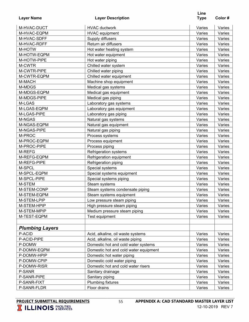
Layer Name Layer Description Line Type Color #
PROJECT SUBMITTAL REQUIREMENTS
55 APPENDIX A: CAD STANDARD MASTER LAYER LIST 12-10-2019 REV 7
M-HVAC-DUCT HVAC ductwork Varies Varies M-HVAC-EQPM HVAC equipment Varies Varies M-HVAC-SDFF Supply diffusers Varies Varies M-HVAC-RDFF Return air diffusers Varies Varies M-HOTW Hot water heating system Varies Varies M-HOTW-EQPM Hot water equipment Varies Varies M-HOTW-PIPE Hot water piping Varies Varies M-CWTR Chilled water system Varies Varies M-CWTR-PIPE Chilled water piping Varies Varies M-CWTR-EQPM Chilled water equipment Varies Varies M-MACH Machine shop equipment Varies Varies M-MDGS Medical gas systems Varies Varies M-MDGS-EQPM Medical gas equipment Varies Varies M-MDGS-PIPE Medical gas piping Varies Varies M-LGAS Laboratory gas systems Varies Varies M-LGAS-EQPM Laboratory gas equipment Varies Varies M-LGAS-PIPE Laboratory gas piping Varies Varies M-NGAS Natural gas systems Varies Varies M-NGAS-EQPM Natural gas equipment Varies Varies M-NGAS-PIPE Natural gas piping Varies Varies M-PROC Process systems Varies Varies M-PROC-EQPM Process equipment Varies Varies M-PROC-PIPE Process piping Varies Varies M-REFG Refrigeration systems Varies Varies M-REFG-EQPM Refrigeration equipment Varies Varies M-REFG-PIPE Refrigeration piping Varies Varies M-SPCL Special systems Varies Varies M-SPCL-EQPM Special systems equipment Varies Varies M-SPCL-PIPE Special systems piping Varies Varies M-STEM Steam systems Varies Varies M-STEM-CONP Steam systems condensate piping Varies Varies M-STEM-EQPM Steam systems equipment Varies Varies M-STEM-LPIP Low pressure steam piping Varies Varies M-STEM-HPIP High pressure steam piping Varies Varies M-STEM-MPIP Medium pressure steam piping Varies Varies M-TEST-EQPM Test equipment Varies Varies Plumbing Layers P-ACID Acid, alkaline, oil waste systems Varies Varies P-ACID-PIPE Acid, alkaline, oil waste piping Varies Varies P-DOMW Domestic hot and cold water systems Varies Varies P-DOMW-EQPM Domestic hot and cold water equipment Varies Varies P-DOMW-HPIP Domestic hot water piping Varies Varies P-DOMW-CPIP Domestic cold water piping Varies Varies P-DOMW-RISR Domestic hot and cold water risers Varies Varies P-SANR Sanitary drainage Varies Varies P-SANR-PIPE Sanitary piping Varies Varies P-SANR-FIXT Plumbing fixtures Varies Varies P-SANR-FLDR Floor drains Varies Varies

Layer Name Layer Description Line Type Color #
PROJECT SUBMITTAL REQUIREMENTS
56 APPENDIX A: CAD STANDARD MASTER LAYER LIST 12-10-2019 REV 7
P-SANR-RISR Sanitary risers Varies Varies P-SANR-EQPM Sanitary equipment Varies Varies P-STRM Storm drainage system Varies Varies P-STRM-PIPE Storm drain piping Varies Varies P-STRM-RISR Storm drain risers Varies Varies P-STRM-RFDR Roof drains Varies Varies P-EQPM Plumbing miscellaneous equipment Varies Varies P-FIXT Plumbing fixtures Varies Varies Structural Layers S-BEAM Structural beam Varies Varies S-BEAM-CNTR Structural beam centerlines Varies Varies S-BRAC-LATL Structural bracing - lateral Varies Varies S-BEAM-PRIM Structural beam - primary (girders) Varies Varies S-BEAM-SCND Structural beam - secondary (girders) Varies Varies S-BRAC-SHEA Structural bracing - shear walls Varies Varies S-BRAC-VERT Structural bracing - vertical Varies Varies S-COLS Structural columns Varies Varies S-COLS-CNTR Structural columns centerlines Varies Varies S-COLS-PRIM Structural columns - primary Varies Varies S-COLS-SCND Structural columns - secondary Varies Varies S-DECK Structural deck Varies Varies S-DECK-FLOR Structural deck - floor Varies Varies S-DECK-OPEN Structural deck - openings and penetrations Varies Varies S-DECK-ROOF Structural deck - roof Varies Varies S-ELEV-IDEN Structural elevation component identification numbers Varies Varies S-ELEV-OTLN Structural elevation building outlines Varies Varies S-ELEV-PATT Structural elevation textures and hatch patterns Varies Varies S-ELEV-SIGN Structural elevation signage Varies Varies S-EVTR-FRAM Structural elevator framing Varies Varies S-FNDN Structural foundation Varies Varies S-FNDN-FTNG Structural foundation footings Varies Varies S-FNDN-GRBM Structural foundation grade beams Varies Varies S-FNDN-IDEN Structural foundation component identification numbers Varies Varies S-FNDN-PILE Structural foundation piles, drilled piers Varies Varies S-FNDN-RBAR Structural foundation reinforcing Varies Varies S-GRAD-ELEV Structural grading - elevated Varies Varies S-GRAD-FLOR Structural grading - floor Varies Varies S-GRAT-ELEV Structural grating - elevated (catwalks) Varies Varies S-GRAT-FLOR Structural grating - floor Varies Varies S-GRID Structural column grid Varies Varies S-GRID-EXTR Structural column grid lines outside building Varies Varies S-GRID-INTR Structural column grid lines inside building Varies Varies S-GRID-DIMS Structural column grid dimensions Varies Varies S-GRID-IDEN Structural column grid identification tags Varies Varies S-JNTS-CNST Structural joints - construction Varies Varies S-JNTS-CTRL Structural joints - control/expansion Varies Varies S-JOIS Structural joist Varies Varies S-JOIS-BRDG Structural joist bridging Varies Varies

Layer Name Layer Description Line Type Color #
PROJECT SUBMITTAL REQUIREMENTS
57 APPENDIX A: CAD STANDARD MASTER LAYER LIST 12-10-2019 REV 7
S-JOIS-PRIM Structural joist - primary Varies Varies S-JOIS-SCND Structural joist - secondary Varies Varies S-METL-MISC Structural metal - miscellaneous Varies Varies S-SECT-IDEN Structural section component identification numbers Varies Varies S-SECT-MBND Structural section - material beyond section cut Varies Varies S-SECT-MCUT Structural section - material cut by section Varies Varies S-SECT-PATT Structural section textures and hatch patterns Varies Varies S-SLAB Structural slab Varies Varies S-SLAB-EDGE Structural slab edge outline Varies Varies S-SLAB-JOIN Structural slab control joints Varies Varies S-SLAB-RBAR Structural slab reinforcing Varies Varies
S-SPPT-MISC Structural support miscellaneous fasteners, anchor bolts Varies Varies
S-STRS-JOIN Structural stair control joints Varies Varies
S-STRS-LADD Structural stair - ladders, ladder handrails, safety guard, grab bars Varies Varies
S-STRS-RBAR Structural stair - reinforcing Varies Varies S-TRUS-UNIT Structural truss unit Varies Varies S-WALL Structural wall Varies Varies S-WALL-CONC Structural wall - concrete Varies Varies
S-WALL-LOAD Structural wall - load bearing concrete masonry unit (CMU) Varies Varies
S-WALL-NONL Structural wall - non-load bearing concrete masonry unit (CMU) Varies Varies
S-WALL-PCST Structural wall - precast Varies Varies S-WALL-STUD Structural wall - steel stud Varies Varies S-WELD-SYMB Structural weld symbols Varies Varies Telecommunication Layers T-ELEC-IDEN Electrical equipment identifiers and leader lines Varies Varies
T-ELEC-EQPM Electrical equipment physical outline of electrical equipment (e.g. cabinets, enclosures, etc.) Varies Varies
T-COMM-JBOX Communication Junction boxes Varies Varies T-BELL-IDEN Bell system identifier tags, symbol modifier and text Varies Varies T-BELL-SYST Bell system symbols Varies Varies
T-DICT-IDEN Dictation system identifier tags, symbol modifier and text Varies Varies
T-DICT-SYST Dictation system symbols Varies Varies
T-CLOK-IDEN Clock system identifier tags, symbol modifier and text Varies Varies T-CLOK-SYST Clock system symbols Varies Varies T-ALRM-IDEN Alarm system identifier tags, symbol modifier and text Varies Varies T-ALRM-SYST Alarm system symbols Varies Varies
T-NURS-IDEN Nurse call system identifier tags, symbol modifier and text Varies Varies
T-NURS-SYST Nurse call system symbols Varies Varies
T-SOUN-IDEN Sound system identifier tags, symbol modifier and text Varies Varies T-SOUN-SYST Sound system symbols Varies Varies

Layer Name Layer Description Line Type Color #
PROJECT SUBMITTAL REQUIREMENTS
58 APPENDIX A: CAD STANDARD MASTER LAYER LIST 12-10-2019 REV 7
T-PHON-IDEN Phone system identifier tags, symbol modifier and text Varies Varies T-PHON-SYST Phone system symbols Varies Varies
T-CATV-IDEN Television system identifier tags, symbol modifier and text Varies Varies
T-CATV-TELE Television system symbols Varies Varies T-CATV-TVAN Television system antenna system symbols Varies Varies
T-DATA-IDEN Data / LAN system identifier tags, symbol modifier and text Varies Varies
T-DATA-SYST Data / LAN system symbols Varies Varies
T-INTC-IDEN Intercom / public address system identifier tags, symbol modifier and text Varies Varies
T-INTC-INPA Intercom / public address system symbols Varies Varies T-INTC-PGNG Intercom / public address: paging system symbols Varies Varies
T-FIRE-IDEN Fire alarm and detection system identifier tags, symbol modifier and text Varies Varies
T-FIRE-SYST Fire alarm and detection system symbols Varies Varies
T-EMS-IDEN Energy management system identifier tags, symbol modifier and text Varies Varies
T-EMS-SYST Energy management system symbols Varies Varies
T-SECR-IDEN Security system identifier tags, symbol modifier and text Varies Varies
T-SECR-SYST Security system symbols Varies Varies T-COMM-COAX Wiring system coax cable Varies Varies
T-COMM-FIBR Wiring system fiber optics cable Varies Varies T-COMM-IDEN Wiring system cable identifiers Varies Varies
T-COMM-MULT Wiring system multi-conductor cable Varies Varies T-COMM-TRAY Wiring system cable trays and wireway symbols Varies Varies
Civil Data collected exterior of the building
Layer Name Layer Description Line Type
Color #
Buildings / Primary Structures C-BLDG-IDEN Building name and location number - annotation Continuous Varies C-BLDG-OTLN Building footprint - exterior wall of the building Continuous Varies
C-BLDG-MINR Building minor (bus-shelter, kiask, information booth) curbs Continuous Varies
C-BLDG-UNDR Building structure underground Hidden Varies C-BLDG-PATT Building hatch pattern Continuous Varies
C-BLDG-DETAIL Building exterior stairs, fire escapes, porches, and canopies, loading docks attached to the building Continuous Varies
Alignments

Layer Name Layer Description Line Type Color #
PROJECT SUBMITTAL REQUIREMENTS
59 APPENDIX A: CAD STANDARD MASTER LAYER LIST 12-10-2019 REV 7
C-ALGN-OBJT Alignments Varies Varies C-ALGN-IDEN Alignment annotation Varies Varies Embankments C-EMBK-CNTL Embankment centerline Varies Varies C-EMBK-EDGE Embankment edge and object lines Varies Varies C-EMBK-IDEN Embankment annotation Continuous Varies Property C-PROP-BRNG Property bearings and distance - annotation Continuous Varies C-PROP-CONS Property construction limits / controls Varies Varies C-PROP-ESMT Property easements with annotation Varies Varies C-PROP-LINE Property lines with annotation Varies Varies C-PROP-PRVT Property private Varies Varies
C-PROP-LTID Property lot identification (ie: parcel number, lot number etc.) Continuous Varies
C-PROP-DETL Property details with annotation (scaled views depicting detailed areas of property) Continuous Varies
C-PROP-MONU Property monumentation (includes all monuments found or set, witness corners) Continuous Varies
C-PROP-RECD Property record data (data aquired by other sources - not as part of the field survey) Continuous Varies
C-PROP-RCID Property record data identification - annotation Continuous Varies Site C-SITE-SIGN Site signage with annotation (ie: building signs) Continuous Varies C-SITE-CMTY Site cemetery with annotation Continuous Varies C-SITE-BPTH Site bicycle path Varies Varies C-SITE-BRCK Site bicycle rack Varies Varies
C-SITE-WALK Site sidewalks, defined trails - crushed stone, pea-gravel, bark etc. Varies Varies
C-SITE-WKID Site sidewalk material identification: crushed stone, pea-gravel, bark etc. - annotation Continuous Varies
C-SITE-FENC Site fencing, chain-link, chain, wood rail, barbed-wire, etc. Varies Varies
C-SITE-FEID Site fencing type identification: chain-link, chain, wood rail, barbed-wire etc. - annotation Continuous Varies
C-SITE-PTNL Site pedestrian tunnel Hidden Varies C-SITE-IDEN Site identification notes - annotation Continuous Varies
C-SITE-MSTR Site minor structure including misc impervious features (example: concrete / asphalt pads etc.) Continuous Varies
C-SITE-MSID Site minor structure identification - annotation Survey
C-SURV-CTRL Survey control point - permanent markers including benchmarks, gps, brass-tablets, stone marker etc Continuous Varies
C-SURV-CTID Survey control point identification Continuous Varies C-SURV-LINE Survey and control line Varies Varies C-SURV-IDEN Survey and control line annotation Varies Varies Topography C-TOPO-BKLN Topography break lines Varies Varies C-TOPO-BORE Topography soil borings Continuous Varies
C-TOPO-BOID Topography soil boring identificaion tags - annotation Continuous Varies

Layer Name Layer Description Line Type Color #
PROJECT SUBMITTAL REQUIREMENTS
60 APPENDIX A: CAD STANDARD MASTER LAYER LIST 12-10-2019 REV 7
C-TOPO-CORD Topography coordinates Continuous Varies C-TOPO-SPOT Topography spot elevations Continuous Varies C-TOPO-MAJR Topography major contours Varies Varies
C-TOPO-MAID Topography major contour identification - annotation Continuous Varies
C-TOPO-MINR Topography minor contours Varies Varies
C-TOPO-MIID Topography minor contour identification - annotation Continuous Varies
C-TOPO-SLOP Topography cut/fill slopes Continuous Varies C-TOPO-SLID Topography cut/fill slope identification - annotation Continuous Varies C-TOPO-IDEN Topography identification notes - annotation Continuous Varies Borrow Areas C-BORW-LINE Borrow area outline Varies Varies C-BORW-IDEN Borrow area identification - annotation Varies Varies Site Utility Systems Chilled Water System
C-CWTR-JUNC Chilled water junction: vaults, manholes, handholes and valve vaults (UIUC) Continuous 200
C-CWTR-JUID
Chilled water junction identification: vaults, manholes, handholes and valve vaults - annotation (UIUC) Continuous 200
C-CWTR-DEVC Chilled water devices: test boxes, storage tanks, valves, meters, pumps, & regulators (UIUC) Continuous 200
C-CWTR-DVID
Chilled water device identification: test boxes, storage tanks, valves, meters, pumps, & regulators (UIUC) Continuous 200
C-CWTR-FTTG Chilled water fittings caps, crosses, reducers & tees etc. (UIUC) Continuous 200
C-CWTR-ABND Chilled water pipe - abandoned (UIUC) Hidden 253 C-CWTR-MSUP Chilled water pipe - supply main (UIUC) Center2 200 C-CWTR-SSUP Chilled water pipe - supply service (UIUC) Center2 200 C-CWTR-MRET Chilled water pipe - return main (UIUC) Center2 200 C-CWTR-SRET Chilled water pipe - return service (UIUC) Center2 200 C-CWTR-ANOD Chilled water anode test station (UIUC) Continuous 200
C-CWTR-STID Chilled water station identification: anode - annotation (UIUC) Continuous 200
C-CWTR-IDEN Chilled water identification notes (UIUC) Continuous 200 Domestic Water System
C-DOMW-JUNC Domestic water junction: vaults, manholes, handholes, pump stations and valve vaults (UIUC) Continuous 5
C-DOMW-JUID
Domestic water junction identification: vaults, manholes, handholes, pump stations and valve vaults - annotation (UIUC) Continuous 5
C-DOMW-DEVC Domestic water devices: storage tanks, valves, meters, & hydrants (UIUC) Continuous 5
C-DOMW-DVID Domestic water device identification: storage tanks, valves, meters, & hydrants - annotation (UIUC) Continuous 5
C-DOMW-FTTG Domestic water fittings caps, crosses, reducers & tees etc. (UIUC) 5
C-DOMW-ABND Domestic water pipe - abandoned (UIUC) Hidden 253 C-DOMW-MAIN Domestic water pipe - main (UIUC) Continuous 5

Layer Name Layer Description Line Type Color #
PROJECT SUBMITTAL REQUIREMENTS
61 APPENDIX A: CAD STANDARD MASTER LAYER LIST 12-10-2019 REV 7
C-DOMW-SERV Domestic water pipe - service (UIUC) Continuous 5 C-DOMW-NPOT Domestic water pipe - non-potable water (UIUC) Continuous 5
C-DOMW-IDEN Domestic water identification notes - annotation (UIUC) Continuous 5
C-DOMW-OTHR-JUNC
Domestic water junction: vaults, manholes, handholes, pump stations and valve vaults (owned or maintained by others) Continuous 7
C-DOMW-OTHR-JUID
Domestic water junction identification: vaults, manholes, handholes, pump stations and valve vaults - annotation (owned or maintained by others) Continuous 7
C-DOMW-OTHR-DEVC Domestic water devices: storage tanks, valves, meters, & hydrants (owned or maintained by others) Continuous 7
C-DOMW-OTHR-DVID
Domestic water device identification: storage tanks, valves, meters, & hydrants - annotation (owned or maintained by others) Continuous 7
C-DOMW-OTHR-FTTG Domestic water fittings caps, crosses, reducers & tees etc. (owned or maintained by others) Continuous 7
C-DOMW-OTHR-ABND Domestic water pipe - abandoned (owned or maintained by others) Hidden 253
C-DOMW-OTHR-MAIN Domestic water pipe - main (owned or maintained by others) Continuous 7
C-DOMW-OTHR-SERV Domestic water pipe - service (owned or maintained by others) Continuous 7
C-DOMW-OTHR-NPOT Domestic water pipe - non-potable (owned or maintained by others) Continuous 7
C-DOMW-OTHR-IDEN Domestic water identification notes - annotation (owned or maintained by others) Continuous 7
Electrical Distribution System Continuous
C-ELEC-JUNC
Electrical junction: vaults, manholes, handholes, junction boxes, pull boxes, pedestals & splices (UIUC) Continuous 1
C-ELEC-JUID
Electrical junction identification: vaults, manholes, handholes, junction boxes, pull boxes, pedestals & splices - annotation (UIUC) Continuous 1
C-ELEC-DEVC
Electrical device: transformers, capacitors, voltage regulators, motors, buses, generators, meters, grounds & markers (UIUC) Continuous 1
C-ELEC-DVID
Electrical device identification: transformers, capacitors, voltage regulators, motors, buses, generators, meters, grounds & markers - annotation (UIUC) Continuous 1
C-ELEC-ABND Electrical cable - abandoned (UIUC) Hidden 253
C-EPRM-IDEN Electrical cable - primary identification notes - annotation (UIUC) Divide2 1
C-EPRM-UNDR Electrical cable - primary underground (UIUC) Divide2 1 C-EPRM-OVHD Electrical cable - primary overhead (UIUC) Divide2 1
C-ESCD-IDEN Electrical cable - secondary identification notes - annotation (UIUC) Divide2 1
C-ESCD-UNDR Electrical cable - secondary underground (UIUC) Divide2 1 C-ESCD-OVHD Electrical cable - secondary overhead (UIUC) Divide2 1

Layer Name Layer Description Line Type Color #
PROJECT SUBMITTAL REQUIREMENTS
62 APPENDIX A: CAD STANDARD MASTER LAYER LIST 12-10-2019 REV 7
C-ESRV-IDEN Electrical cable - service identification notes - annotation (UIUC) Divide2 1
C-ESRV-UNDR Electrical cable - service underground (UIUC) Divide2 1 C-ELEC-DUCT Electrical ductbanks (UIUC) Divide2 1 C-ELEC-SUBS Electrical sub-stations (UIUC) Continuous 1 C-ELEC-DIST Electrical distribution centers (UIUC) Continuous 1
C-ELEC-SWCH
Electrical switches fuse cutouts, pole mounted switches, circuit breakers, gang operated disconnects, reclosers, cubicle switches (UIUC) Continuous 1
C-ELEC-PDBL Electrical pole - double (UIUC) Continuous 1 C-ELEC-PRSR Electrical pole - risers (UIUC) Continuous 1 C-ELEC-PTWR Electrical pole - tower (UIUC) Continuous 1 C-ELEC-PSGL Electrical pole - single (UIUC) Continuous 1 C-ELEC-PDGY Electrical pole - down guy (UIUC) Continuous 1 C-ELEC-PSPN Electrical pole - span guy wires (UIUC) Continuous 1
C-ELEC-POID Electrical pole - identification tags - annotation (UIUC) Continuous 1
C-ELEC-IDEN Electrical identification notes - annotation (UIUC) Continuous 1
C-ELEC-OTHR-JUNC
Electrical junction: vaults, manholes, handholes, junction boxes, pull boxes, pedestals & splices (owned or maintained by others) Continuous 7
C-ELEC-OTHR-JUID
Electrical junction identification: vaults, manholes, handholes, junction boxes, pull boxes, pedestals & splices - annotation (owned or maintained by others) Continuous 7
C-ELEC-OTHR-DEVC
Electrical device: transformers, capacitors, voltage regulators, motors, buses, generators, meters, grounds & markers (owned or maintained by others) Continuous 7
C-ELEC-OTHR-DVID
Electrical device identification: transformers, capacitors, voltage regulators, motors, buses, generators, meters, grounds & markers - annotation (owned or maintained by others) Continuous 7
C-ELEC-OTHR-ABND Electrical cable - abandoned (owned or maintained by others) Hidden 253
C-EPRM-OTHR-IDEN Electrical cable - primary identification notes - annotation (owned or maintained by others) Dashed 7
C-EPRM-OTHR-UNDR Electrical cable - primary underground (owned or maintained by others) Dashed 7
C-EPRM-OTHR-OVHD Electrical cable - primary overhead ( owned or maintained by others) Dashed 7
C-ESCD-OTHR-IDEN Electrical cable - secondary identification notes - annotation (owned or maintained by others) Dashed 7
C-ESCD-OTHR-UNDR Electrical cable - secondary underground (owned or maintained by others) Dashed 7
C-ESCD-OTHR-OVHD Electrical cable - secondary overhead (owned or maintained by others) Dashed 7
C-ESRV-OTHR-IDEN Electrical cable - service identification notes - annotation ( owned or maintained by others) Dashed 7
C-ESRV-OTHR-UNDR Electrical cable - service underground ( owned or maintained by others) Dashed 7

Layer Name Layer Description Line Type Color #
PROJECT SUBMITTAL REQUIREMENTS
63 APPENDIX A: CAD STANDARD MASTER LAYER LIST 12-10-2019 REV 7
C-ELEC-OTHR-DUCT Electrical ductbanks (owned or maintained by others) Dashed 7
C-ELEC-OTHR-SUBS Electrical sub-stations (owned or maintained by others) Continuous 7
C-ELEC-OTHR-DIST Electrical distribution centers (owned or maintained by others) Continuous 7
C-ELEC-OTHR-SWCH
Electrical switches fuse cutouts, pole mounted switches, circuit breakers, gang operated disconnects, reclosers, cubicle switches (owned or maintained by others) Continuous 7
C-ELEC-OTHR-PDBL Electrical pole - double (owned or maintained by others) Continuous 7
C-ELEC-OTHR-PRSR Electrical pole - risers (owned or maintained by others) Continuous 7
C-ELEC-OTHR-PTWR Electrical pole - tower (owned or maintained by others) Continuous 7
C-ELEC-OTHR-PSGL Electrical pole - single (owned or maintained by others) Continuous 7
C-ELEC-OTHR-PDGY Electrical pole - down guy (owned or maintained by others) Continuous 7
C-ELEC-OTHR-PSPN Electrical pole - span guy wires (owned or maintained by others) Continuous 7
C-ELEC-OTHR-POID Electrical pole - identification tags - annotation (owned or maintained by others) Continuous 7
C-ELEC-OTHR-TGRD Electrical tower ground wire (owned or maintained by others Continous 7
C-ELEC-OTHR-IDEN Electrical identification notes - annotation (owned or maintained by others) Continuous 7
Energy Management System (EMS)
C-EMS-JUNC Energy management system junction: pull boxes, manholes, handholes, pedestals, splices (UIUC) Continuous 1
C-EMS-JUID
Energy management system junction identification: pull boxes, manholes, handholes, pedestals, splices - annotation (UIUC) Continuous 1
C-EMS-DEVC Energy management system devices: field interfaces, multiplexers, markers (UIUC) Continuous 1
C-EMS-DVID
Energy management system device identification: field interfaces, multiplexers, markers - annotation (UIUC) Continuous 1
C-EMS-ABND Energy management system cable - abandoned (UIUC) Hidden 253
C-EMS-OVHD Energy management system cable - overhead (UIUC) Continuous 5
C-EMS-UNDR Energy management system cable - underground (UIUC) Continuous 5
C-EMS-DUCT Energy management system ductbanks (UIUC) Dashed 7 Fire Protection System
C-FIRE-JUNC Fire protection junction: vaults, manholes, handholes, pump stations and valve vaults (UIUC) Continuous 5

Layer Name Layer Description Line Type Color #
PROJECT SUBMITTAL REQUIREMENTS
64 APPENDIX A: CAD STANDARD MASTER LAYER LIST 12-10-2019 REV 7
C-FIRE-JUID
Fire protection junction identification: vaults, manholes, handholes, pump stations and valve vaults - annotation (UIUC) Continuous 5
C-FIRE-DEVC Fire protection devices: storage tanks, valves, meters & hydrants (UIUC) Continuous 5
C-FIRE-DVID Fire protection device identification: storage tanks, valves, hydrants, & meters - annotation (UIUC) Continuous 5
C-FIRE-FTTG Fire protection fittings caps, crosses, reducers & tees etc. (UIUC) Continuous 5
C-FIRE-ABND Fire protection pipe - abandoned (UIUC) Hidden 253 C-FIRE-MAIN Fire protection pipe - main (UIUC) Continuous 5 C-FIRE-SERV Fire protection pipe - service (UIUC) Continuous 5
C-FIRE-IDEN Fire protection identification notes - annotation (UIUC) Continuous 5
C-FIRE-OTHR-JUNC
Fire protection junction: vaults, manholes, handholes, pump stations and valve vaults (owned or maintained by others) Continuous 7
C-FIRE-OTHR-JUID
Fire protection junction identification: vaults, manholes, handholes, pump stations and valve vaults - annotation (owned or maintained by others) Continuous 7
C-FIRE-OTHR-DEVC Fire protection devices: storage tanks, valves, valve vaults, meters (owned or maintained by others) Continuous 7
C-FIRE-OTHR-DVID
Fire protection device identification: storage tanks, valves, meters - annotation (owned or maintained by others) Continuous 7
C-FIRE-OTHR-FTTG Fire protection fittings caps, crosses, reducers & tees etc. (owned or maintained by others) Continuous 7
C-FIRE-OTHR-ABND Fire protection pipe - abandoned (owned or maintained by others) Hidden 253
C-FIRE-OTHR-MAIN Fire protection pipe - main (owned or maintained by others) Continuous 7
C-FIRE-OTHR-SERV Fire protection pipe - service (owned or maintained by others) Continuous 7
C-FIRE-OTHR-IDEN Fire protection identification notes - annotation (owned or maintained by others) Continuous 7
Fuel System
C-FUEL-JUNC
Fuel system junction: hydrant fill points, vaults, manholes, handholes, test boxes, vent vaults, valve vaults, and hydrant control vaults and valves (UIUC) Continuous 7
C-FUEL-JUID
Fuel system junction identification: hydrant fill points, vaults, manholes, handholes, test boxes, vent vaults, valve vaults, and hydrant control vaults and valves - annotation (UIUC) Continuous 7
C-FUEL-DEVC
Fuel system devices: air eliminators, filter strainers, line vents, markers, meters, oil/water separators, pumps, regulators, and tanks (UIUC) Continuous 7
C-FUEL-DVID
Fuel system device identification: air eliminators, filter strainers, line vents, markers, meters, oil/water separators, pumps, regulators, and tanks - annotation (UIUC) Continuous 7

Layer Name Layer Description Line Type Color #
PROJECT SUBMITTAL REQUIREMENTS
65 APPENDIX A: CAD STANDARD MASTER LAYER LIST 12-10-2019 REV 7
C-FUEL-FTTG Fuel system fittings caps, crosses, reducers & tees etc. (UIUC) Continuous 7
C-FUEL-ABND Fuel system pipe - abandoned (UIUC) Hidden 253 C-FUEL-MAIN Fuel system pipe - main (UIUC) Continuous 7 C-FUEL-SERV Fuel system pipe - service (UIUC) Continuous 7 C-FUEL-DEFL Fuel system pipe - defueling (UIUC) Continuous 7 C-FUEL-ANOD Fuel system anode test station (UIUC) Continuous 7 C-FUEL-BOOS Fuel system booster station (UIUC) Continuous 7 C-FUEL-REDC Fuel system reducing station (UIUC) Continuous 7 C-FUEL-PUMP Fuel system pumping station (UIUC) Continuous 7 C-FUEL-IDEN Fuel system identification notes - annotation (UIUC) Continuous 7
C-FUEL-OTHR-JUNC
Fuel system junction: hydrant fill points, vaults, manholes, handholes, test boxes, vent vaults, valve vaults, and hydrant control vaults and valves (owned or maintained by others) Continuous 7
C-FUEL-OTHR-JUID
Fuel system junction identification: hydrant fill points, vaults, manholes, handholes, test boxes, vent vaults, valve vaults, and hydrant control vaults and valves - annotation (owned or maintained by others) Continuous 7
C-FUEL-OTHR-DEVC
Fuel system devices: air eliminators, filter strainers, line vents, markers, meters, oil/water separators, pumps, regulators, and tanks (owned or maintained by others) Continuous 7
C-FUEL-OTHR-DVID
Fuel system device identification: air eliminators, filter strainers, line vents, markers, meters, oil/water separators, pumps, regulators, and tanks - annotation (owned or maintained by others) Continuous 7
C-FUEL-OTHR-FTTG Fuel system fittings caps, crosses, reducers & tees etc. (owned or maintained by others) Continuous 7
C-FUEL-OTHR-ABND Fuel system pipe - abandoned (owned or maintained by others) Hidden 253
C-FUEL-OTHR-MAIN Fuel system pipe - main (owned or maintained by others) Continuous 7
C-FUEL-OTHR-SERV Fuel system pipe - service (owned or maintained by others) Continuous 7
C-FUEL-OTHR-DEFL Fuel system pipe - defueling (owned or maintained by others) Continuous 7
C-FUEL-OTHR-ANOD Fuel system anode test station (owned or maintained by others) Continuous 7
C-FUEL-OTHR-BOOS Fuel system booster station (owned or maintained by others) Continuous 7
C-FUEL-OTHR-REDC Fuel system reducing station (owned or maintained by others) Continuous 7
C-FUEL-OTHR-PUMP Fuel system pumping station (owned or maintained by others) Continuous 7
C-FUEL-OTHR-IDEN Fuel system identification notes - annotation (owned or maintained by others) Continuous 7
Lighting System
C-LITE-JUNC Lighting junctions: pull boxes, manholes, handholes, pedestals, splices (UIUC) Continuous 1

Layer Name Layer Description Line Type Color #
PROJECT SUBMITTAL REQUIREMENTS
66 APPENDIX A: CAD STANDARD MASTER LAYER LIST 12-10-2019 REV 7
C-LITE-JUID
Lighting junction identification: pull boxes, manholes, handholes, pedestals, splices - annotation (UIUC) Continuous 1
C-LITE-FLOD Lighting flood lights (UIUC) Continuous 1 C-LITE-POLE Lighting pole mounted light (UIUC) Continuous 1 C-LITE-STRT Lighting street lights (UIUC) Continuous 1 C-LITE-WALK Lighting walkway lights (UIUC) Continuous 1
C-LITE-SWCH
Lighting switches fuse cutouts, pole mounted switches, circuit breakers, gang operated disconnects, reclosers, cubicle switches (UIUC) Continuous 1
C-LITE-ABND Lighting cable - abandoned (UIUC) Hidden 253
C-LITE-PRID Lighting cable - primary identification notes - annotation (UIUC) Border2 1
C-LITE-PRUN Lighting cable - primary underground (UIUC) Border2 1 C-LITE-PROH Lighting cable - primary overhead (UIUC) Border2 1
C-LITE-SCID Lighting cable - secondary identification notes - annotation (UIUC) Continuous 1
C-LITE-SCUN Lighting cable - secondary underground (UIUC) Border2 1 C-LITE-SCOH Lighting cable - secondary overhead (UIUC) Border2 1
C-LITE-SRID Lighting cable - service identification notes - annotation (UIUC) Continuous 1
C-LITE-SRUN Lighting cable - service underground (UIUC) Border2 1
C-LITE-OTHR-JUNC
Lighting junctions: pull boxes, manholes, handholes, pedestals, splices (owned or maintained by others) Continuous 7
C-LITE-OTHR-JUID
Lighting junction identification: pull boxes, manholes, handholes, pedestals, splices - annotation (owned or maintained by others) Continuous 7
C-LITE-OTHR-FLOD Lighting flood lights (owned or maintained by others) Continuous 7
C-LITE-OTHR-POLE Lighting pole mounted light (owned or maintained by others) Continuous 7
C-LITE-OTHR-STRT Lighting street lights (owned or maintained by others) Continuous 7
C-LITE-OTHR-WALK Lighting walkway lights (owned or maintained by others) Continuous 7
C-LITE-OTHR-SWCH
Lighting switches fuse cutouts, pole mounted switches, circuit breakers, gang operated disconnects, reclosers, cubicle switches (owned or maintained by others) Continuous 7
C-LITE-OTHR-ABND Lighting cable - abandoned (owned or maintained by others) Hidden 253
C-LITE-OTHR-PRID Lighting cable - primary identification notes - annotation (owned or maintained by others) Dashed 7
C-LITE-OTHR-PRUN Lighting cable - primary underground (owned or maintained by others) Dashed 7
C-LITE-OTHR-PROH Lighting cable - primary overhead (owned or maintained by others) Dashed 7
C-LITE-OTHR-SCID Lighting cable - secondary identification notes - annotation (owned or maintained by others) Continuous 7

Layer Name Layer Description Line Type Color #
PROJECT SUBMITTAL REQUIREMENTS
67 APPENDIX A: CAD STANDARD MASTER LAYER LIST 12-10-2019 REV 7
C-LITE-OTHR-SCUN Lighting cable - secondary underground (owned or maintained by others) Dashed 7
C-LITE-OTHR-SCOH Lighting cable - secondary overhead (owned or maintained by others) Dashed 7
C-LITE-OTHR-SRID Lighting cable - service identification notes - annotation (owned or maintained by others) Continuous 7
C-LITE-OTHR-SRUN Lighting cable - service underground (owned or maintained by others) Dashed 7
Natural Gas Distribution
C-NGAS-JUNC
Natural gas junction: hydrant fill points, vaults, manholes, handholes, test boxes, vent vaults, and valve vaults (UIUC) Continuous 52
C-NGAS-JUID
Natural gas junction identification: hydrant fill points, vaults, manholes, handholes, test boxes, vent vaults, and valve vaults - annotation (UIUC) Continuous 52
C-NGAS-DEVC Natural gas devices: vents, markers, meters, pumps, regulators, tanks, taps, and valves (UIUC) Continuous 52
C-NGAS-DVID
Natural gas device identification: vents, markers, meters, pumps, regulators, tanks, taps, and valves - annotation (UIUC) Continuous 52
C-NGAS-ABND Natural gas pipe - abandoned (UIUC) Hidden 253 C-NGAS-MAIN Natural gas pipe - main (UIUC) Continuous 52 C-NGAS-SERV Natural gas pipe - service (UIUC) Continuous 52 C-NGAS-ANOD Natural gas anode test station (UIUC) Continuous 52 C-NGAS-BOOS Natural gas booster station (UIUC) Continuous 52 C-NGAS-REDC Natural gas reducing station (UIUC) Continuous 52 C-NGAS-PUMP Natural gas pumping station (UIUC) Continuous 52
C-NGAS-STID Natural gas station identification tags: anode test, booster, reducing, pumping - annotation (UIUC) Continuous 52
C-NGAS-IDEN Natural gas identification notes - annotation (UIUC) Continuous 52 C-NGAS-CVNT Natural gas casing vent (UIUC) Varies Varies C-NGAS-WSGN Natural gas warning sign (UIUC) Varies Varies C-NGAS-LSTA Natural gas located station (UIUC) Varies Varies C-NGAS-TRAN-MAIN Natural gas transmission main (UIUC) Varies Varies C-NGAS-TRAN-ACAN Natural gas transmission anode canister (UIUC) Varies Varies C-NGAS-TRAN-RWRE Natural gas transmission rectifier wire (UIUC) Varies Varies C-NGAS-TRAN-RSTA Natural gas transmission rectifier station (UIUC) Varies Varies C-NGAS-TRAN-GSTA Natural gas transmission gas station (UIUC) Varies Varies C-GSLP-SERV LP Gas service (UIUC) Varies Varies
C-NGAS-OTHR-JUNC
Natural gas junction: hydrant fill points, vaults, manholes, handholes, test boxes, vent vaults, and valve vaults (owned or maintained by others) Continuous 7
C-NGAS-OTHR-JUID
Natural gas junction identification: hydrant fill points, vaults, manholes, handholes, test boxes, vent vaults, and valve vaults - annotation (owned or maintained by others) Continuous 7
C-NGAS-OTHR-DEVC
Natural gas devices: vents, markers, meters, pumps, regulators, tanks, taps, and valves (owned or maintained by others) Continuous 7

Layer Name Layer Description Line Type Color #
PROJECT SUBMITTAL REQUIREMENTS
68 APPENDIX A: CAD STANDARD MASTER LAYER LIST 12-10-2019 REV 7
C-NGAS-OTHR-DVID
Natural gas device identification: vents, markers, meters, pumps, regulators, tanks, taps, and valves - annotation (owned or maintained by others) Continuous 7
C-NGAS-OTHR-ABND Natural gas pipe - abandoned (owned or maintained by others) Hidden 253
C-NGAS-OTHR-MAIN Natural gas pipe - main (owned or maintained by others) Dashed 7
C-NGAS-OTHR-SERV Natural gas pipe - service (owned or maintained by others) Dashed 7
C-NGAS-OTHR-ANOD Natural gas anode test station (owned or maintained by others) Continuous 7
C-NGAS-OTHR-BOOS Natural gas booster station (owned or maintained by others) Continuous 7
C-NGAS-OTHR-REDC Natural gas reducing station (owned or maintained by others) Continuous 7
C-NGAS-OTHR-PUMP Natural gas pumping station (owned or maintained by others) Continuous 7
C-NGAS-OTHR-STID
Natural gas station identification tags: anode test, booster, reducing, & pumping - annotation (owned or maintained by others) Continuous 7
C-NGAS-OTHR-IDEN Natural gas identification notes - annotation (owned or maintained by others) Continuous 7
Steam Distribution System
C-STEA-JUNC Steam distribution junction: vaults and manholes (UIUC)
C-STEA-JUID Steam distribution junction identification: vaults and manholes (UIUC)
C-STEA-DEVC Steam distribution devices vaults, traps, condensate pumps (UIUC) Continuous 211
C-STEA-DVID Steam distribution device identification tags: vaults, traps, condensate pumps - annotation (UIUC) Continuous 211
C-STEA-ABND Steam distribution abandoned tunnels, piping (UIUC) Hidden 253
C-STEA-STNL Steam distribution shallow tunnel (UIUC) Phantom2 211 C-STEA-TUNL Steam distribution tunnel (UIUC) Phantom2 211 C-STEA-TRAP Steam distribution trap (UIUC) Varies Varies C-STEA-UGEC Steam distribution underground enclosure (UIUC) Varies Varies C-STEA-LP Steam distribution: low pressure piping (UIUC) Center2 211 C-STEA-UP Steam distribution: utility pressure piping (UIUC) Center2 211 C-STEA-HP Steam distribution: high pressure piping (UIUC) Center2 211 C-STEA-CR Steam distribution: condensate return piping (UIUC) Center2 211 C-STEA-PR Steam distribution: pressure return (UIUC) Center2 211 C-STEA-VR Steam distribution: vacuum return (UIUC) Center2 211 C-STEA-IDEN Steam distribution identification notes (UIUC) Continuous 211 Sanitary Sewer System
C-SSWR-JUNC Sanitary sewer junction: manholes and lift-stations (UIUC) Continuous 3
C-SSWR-JUID Sanitary sewer junction identification: manholes and lift-stations - annotation (UIUC) Continuous 3

Layer Name Layer Description Line Type Color #
PROJECT SUBMITTAL REQUIREMENTS
69 APPENDIX A: CAD STANDARD MASTER LAYER LIST 12-10-2019 REV 7
C-SSWR-DEVC Sanitary sewer devices: cleanouts and air-release valves (UIUC) Continuous 3
C-SSWR-DVID Sanitary sewer device identification: cleanouts and air-release valves - annotation (UIUC) Continuous 3
C-SSWR-GSYM Sanitary sewer graphic symbol Continuous 3
C-SSWR-UGEC Sanitary sewer underground enclosure Continuous 3 C-SSWR-ABND Sanitary sewer pipe - abandoned (UIUC) Hidden 253 C-SSWR-MAIN Sanitary sewer pipe - main (UIUC) DashDot2 3 C-SSWR-SERV Sanitary sewer pipe - service (UIUC) DashDot2 3 C-SSWR-FRCM Sanitary sewer pipe - forcemain (UIUC) Hidden 3 C-SSWR-SEPT Sanitary sewer septic systems (UIUC) DashDot2 3 C-SSWR-ARRW Sanitary sewer direction of flow arrows (UIUC) Continuous 3
C-SSWR-IDEN Sanitary sewer identification notes - annotation (UIUC) Continuous 3
C-SSWR-AGEC Sanitary sewer above ground enclosure Continuous 3
C-SSWR-OTHR-JUNC Sanitary sewer junction: manholes and lift-stations (owned or maintained by others) Continuous 7
C-SSWR-OTHR-JUID
Sanitary sewer junction identification: manholes and lift-stations - annotation (owned or maintained by others) Continuous 7
C-SSWR-OTHR-DEVC Sanitary sewer devices: cleanouts and air-release valves (owned or maintained by others) Continuous 7
C-SSWR-OTHR-DVID
Sanitary sewer device identification: cleanouts and air-release valves - annotation (owned or maintained by others) Continuous 7
C-SSWR-OTHR-UGEC Sanitary sewer underground enclosure (owned or maintained by others) Continuous 7
C-SSWR-OTHR-ABND Sanitary sewer pipe - abandoned (owned or maintained by others) Hidden 253
C-SSWR-OTHR-MAIN Sanitary sewer pipe - main (owned or maintained by others) Dashed 7
C-SSWR-OTHR-SERV Sanitary sewer pipe - service (owned or maintained by others) Dashed 7
C-SSWR-OTHR-SEPT Sanitary sewer septic systems (owned or maintained by others) Dashed 7
C-SSWR-OTHR-FRCM Sanitary sewer forcemain (owned or maintained by others) Hidden 7
C-SSWR-OTHR-ARRW Sanitary sewer direction of flow arrows (owned or maintained by others) Continuous 7
C-SSWR-OTHR-IDEN Sanitary sewer identification notes - annotation (owned or maintained by others) Continuous 7
Storm Drainage System
C-STRM-JUNC
Storm drainage junction: manholes, curb inlets, catch basins, drainage inlets, and storm drains (UIUC) Continuous 70

Layer Name Layer Description Line Type Color #
PROJECT SUBMITTAL REQUIREMENTS
70 APPENDIX A: CAD STANDARD MASTER LAYER LIST 12-10-2019 REV 7
C-STRM-JUID
Storm drainage junction identification: manholes, curb inlets, catch basins, drainage inlets, and storm drains - annotation (UIUC) Continuous 70
C-STRM-DEVC Storm drainage devices: headwalls, cleanouts, downspouts, culverts and air-release valves (UIUC) Continuous 70
C-STRM-DVID
Storm drainage device identification: headwalls, cleanouts, downspouts, culverts and air-release valves (UIUC) Continuous 70
C-STRM-GSYM Storm sewer graphic symbol Continuous 70 C-STRM-ABND Storm drainage pipe - abandoned (UIUC) Hidden 253 C-STRM-MAIN Storm drainage pipe - main (UIUC) Hidden 70 C-STRM-SERV Storm drainage pipe - service (UIUC) Hidden 70 C-STRM-UDRN Storm drainage pipe - underdrain (UIUC) Hidden 70 C-STRM-FRCM Storm drainage pipe - forcemain (UIUC) Hidden 70 C-STRM-ARRW Storm drainage direction of flow arrows (UIUC) Continuous 70
C-STRM-POND Storm drainage detention basins, retention basins with annotation (UIUC) Continuous Varies
C-STRM-DTCH Storm drainage swales / ditches with annotation (UIUC) Continuous Varies
C-STRM-EROS Storm drainage erosion control with annotation (UIUC) Continuous Varies
C-STRM-IDEN Storm drainage identification notes - annotation (UIUC) Continuous Varies
C-STRM-OTHR-JUNC
Storm drainage junction: manholes, curb inlets, catch basins, drainage inlets, and storm drains (owned or maintained by others) Continuous 7
C-STRM-OTHR-JUID
Storm drainage junction identification: manholes, curb inlets, catch basins, drainage inlets, and storm drains - annotation (owned or maintained by others) Continuous 7
C-STRM-OTHR-DEVC
Storm drainage devices: headwalls, cleanouts, downspouts, culverts and air-release valves (owned or maintained by others) Continuous 7
C-STRM-OTHR-DVID
Storm drainage device identification: headwalls, cleanouts, downspouts, culverts and air-release valves (owned or maintained by others) Continuous 7
C-STRM-OTHR-ABND Storm drainage pipe - abandoned (owned or maintained by others) Hidden 7
C-STRM-OTHR-MAIN Storm drainage pipe - main (owned or maintained by others) Hidden 7
C-STRM-OTHR-SERV Storm drainage pipe - service (owned or maintained by others) Hidden 7
C-STRM-OTHR-UDRN Storm drainage pipe - underdrain (owned or maintained by others) Hidden 7
C-STRM-OTHR-FRCM Storm drainage pipe - forcemain (owned or maintained by others) Hidden 7
C-STRM-OTHR-ARRW Storm drainage direction of flow arrows (owned or maintained by others) Continuous 7
C-STRM-OTHR-IDEN Storm drainage identification notes - annotation (owned or maintained by others) Continuous 7
Telecommunications System Continuous 7

Layer Name Layer Description Line Type Color #
PROJECT SUBMITTAL REQUIREMENTS
71 APPENDIX A: CAD STANDARD MASTER LAYER LIST 12-10-2019 REV 7
C-TELE-JUNC
Telecommunication system junction: vaults, manholes, handholes, junction boxes, pull boxes, pedestals & splices (UIUC) Continuous 7
C-TELE-JUID
Telecommunication system junction identification: vaults, manholes, handholes, junction boxes, pull boxes, pedestals and splices (UIUC) Continuous 7
C-TELE-ABND Telecommunication system conduit, cable, fiber optics - abandoned (UIUC) Hidden 253
C-TELE-TOWR Telecommunication system tower Continuous 7 C-TELE-MAIN Telecommunication system conduit - main (UIUC) Continuous 7 C-TELE-SERV Telecommunication system conduit - service (UIUC) Continuous 7
C-TELE-DBRY Telecommunication system cable - direct burried (UIUC) Continuous 7
C-TELE-FIBR Telecommunication system fiber optic (UIUC) Continuous 7
C-TELE-IDEN Telecommunication system identification notes - annotation (UIUC) Continuous 7
Site Transportation System Road System C-ROAD-BRDG Road bridge Continuous Varies C-ROAD-FLCB Transportation road flowline curb Continuous Varies C-ROAD-TBCB Transportation road top back of curb Continuous Varies C-ROAD-RWAY Transportation road rights-of-way, with markers Continuous Varies C-ROAD-CNTR Transportation road centerlines Continuous Varies
C-ROAD-CNID Transportation road centerline identification - annotation Continuous Varies
C-ROAD-GARD Transportation road guardrails Continuous Varies C-ROAD-IDEN Transportation road identification - annotation Continuous Varies
C-ROAD-PVID Transportation road pavement type identification - annotation Continuous Varies
C-ROAD-SIGN Transportation road signage with annotation Continuous Varies
C-ROAD-MINR Transportation minor roads (crushed stone, dirt, oil and chip) not defined by curbs Continuous Varies
Parking System C-PKNG-CARS Parking lot graphic illustration of cars Continuous Varies C-PKNG-CNID Parking lot centerline identification - annotation Continuous Varies C-PKNG-CNTR Parking lot centerlines Continuous Varies C-PKNG-CURB Parking lot curbs, parking bumpers, islands Continuous Varies C-PKNG-DRAN Parking lot drainage slope indications Continuous Varies C-PKNG-SPID Parking lot space identification - annotation Continuous Varies C-PKNG-IDEN Parking lot identification - annotation Continuous Varies C-PKNG-SIGN Parking lot signage with annotation Continuous Varies
C-PKNG-PVMK
Parking lot pavement markings (space stripes, handicapped symbols, Right/Left/Straight turn arrows etc.) Continuous Varies
Railroad System C-RAIL-CNID Railroad centerline identification - annotation Varies Varies C-RAIL-CNTR Railroad centerline Center Varies C-RAIL-BRDG Railroad bridge structure Varies Varies C-RAIL-RAIL Railroad rails Varies Varies

Layer Name Layer Description Line Type Color #
PROJECT SUBMITTAL REQUIREMENTS
72 APPENDIX A: CAD STANDARD MASTER LAYER LIST 12-10-2019 REV 7
C-RAIL-SIGN Railroad signage with annotation Varies Varies Site Landscaping Plants L-PLNT-TREE Landscape plant trees & hedge rows Varies Varies
L-PLNT-TRID Landscape plant trees identification tags: decidous, coniferous and hedge rows etc. - annotation Varies Varies
L-PLNT-GRND Landscape plant ground covers and vines Varies Varies
L-PLNT-BEDS Landscape plant rock, bark, and other Landscape beds, planters Varies Varies
L-PLNT-TURF Landscape plant lawn areas Varies Varies Irrigation System
L-IRRIG-JUNC Landscape irrigation system junction: manholes, vaults, and valve vault (UIUC) Varies Varies
L-IRRIG-JUID
Landscape irrigation system junction identification: manholes, vaults, and valve vault - annotation (UIUC) Varies Varies
L-IRRIG-DEVC Landscape irrigation system devices: valves, meters, sprinkler heads and hydrants (UIUC) Varies Varies
L-IRRIG-DVID
Landscape irrigation system device identification: valves, meters, sprinkler heads and hydrants (UIUC) Varies Varies
L-IRRIG-ABND Landscape irrigation system pipe - abandoned (UIUC) Hidden 253
L-IRRIG-MAIN Landscape irrigation system pipe - main (UIUC) Varies Varies L-IRRIG-SERV Landscape irrigation system pipe - service (UIUC) Varies Varies Structures L-SITE-WALL Landscape site retaining walls Varies Varies L-SITE-STEP Landscape site steps (not attached to buildings) Varies Varies L-SITE-DECK Landscape site decks Varies Varies L-SITE-BRDG Landscape site bridges Varies Varies L-SITE-POOL Landscape site pools and spas Varies Varies L-SITE-SPRT Landscape site sports fields Varies Varies L-SITE-PLAY Landscape site play structures Varies Varies
L-SITE-STRC Landscape site structures for ecstatic purposes (brick columns, concrete benches, statues, etc.) Varies Varies
Hydroseeding L-HYDR-IDEN Hydroseeding annotation Varies Varies L-HYDR-GENL Hydroseeding Varies Varies L-HYDR-SEED Hydroseeding seed Varies Varies L-HYDR-SODS Hydroseeding sod Varies Varies L-HYDR-SPRG Hydroseeding sprigs Varies Varies L-HYDR-SDSD Hydroseeding seed and sod Varies Varies L-HYDR-SDSG Hydroseeding seed and sprig Varies Varies L-HYDR-SSSG Hydroseeding seed, sod, and sprig Varies Varies Turfing L-TURF-IDEN Turfing annotation Varies Varies L-TURF-MLCH Turfing mulch outlines Varies Varies Seeding L-SEED-IDEN Seeding annotation Varies Varies L-SEED-SDSD Seeding seed and sod Varies Varies

Layer Name Layer Description Line Type Color #
PROJECT SUBMITTAL REQUIREMENTS
73 APPENDIX A: CAD STANDARD MASTER LAYER LIST 12-10-2019 REV 7
L-SEED-SSSG Seeding seed, sod, and sprig Varies Varies L-SEED-SDSG Seeding seed and sprig Varies Varies L-SEED-SODS Seeding sod Varies Varies L-SEED-GENL Seeding seed Varies Varies

PROJECT SUBMITTAL REQUIREMENTS
74 APPENDIX B: SPACE INVENTORY DRAWINGS
12-10-2019 REV 7
APPENDIX B: SPACE INVENTORY DRAWINGS
Drawing 00100-1: Space Inventory – Room Numbering System Drawing 00100-2: Space Inventory – Actual Room Use Assigned Drawing 00100-3: Space Inventory – Area Polylines

PROJECT SUBMITTAL REQUIREMENTS
75 APPENDIX B: SPACE INVENTORY DRAWINGS
12-10-2019 REV 7

PROJECT SUBMITTAL REQUIREMENTS
76 APPENDIX B: SPACE INVENTORY DRAWINGS 12-10-2019 REV 7

PROJECT SUBMITTAL REQUIREMENTS
77 APPENDIX B: SPACE INVENTORY DRAWINGS 12-10-2019 REV 7

PROJECT SUBMITTAL REQUIREMENTS
78 APPENDIX C: CHANGE LOG
12-10-2019 REV 7
APPENDIX C: CHANGE LOG
Rev- # Date Change(s) Made 7 12-10-19 Added new F&S Logo. Changed acceptable autocad version to 2017 (part 1, 7a, 3, b). 6 10-05-18 Definitions – added bid documents on page 2.
Deliverable formatting – added ‘Electronic “e”’ and ‘Bound Deliverables’ Change/clarify the file naming conventions with examples used throughout the Deliverables. If individual submittals are bound into a single binder/submittal as long as the cover lists all
deliverables included in the binder. Allowed through DD only. Removed paper format for item 02. Changed item 04a to include “Studies.” Clarified on 06 – Label for Bidding and Closeout. There is no 100%CD. Clarified on 07 – Label for Bidding and Closeout which should be on all pages. There is no
100%CD. Corrected the title of item 09 on page 2. Change/clarify how item 09 comes in to F&S (add that it should come in on CD and digital only).
Clarified methods of electronic delivery on item 08. Updated website link and method of submittal on item 09. If individual submittals are bound into a single binder/submittal as long as the cover lists all
deliverables included in the binder. Allowed through DD only. 7a,1,i,ii – updated signature requirements from wet only to wet, scanned, or digital
5 10-5-17 Added additional deliverables from the “Required Phases & Minimum List of Deliverables.” Added submittal requirements for all added deliverables. Provided submittal requirements for Feasibility Studies, Memorandums or Short Reports and Conceptualizations. Changed Exhibits and Drawings sections to Appendices. Added the additional requirement of a single “back-to-back” pdf format. Added Part 4: GIS Standards.
4 11-28-12 Part 1, E, 5 – removed Part 1, G, 2, a – added “staples, or post bindings” Part 1, F, 3 – remove (O&M copies and warranties covered in Project Manual) Part 1, F, 4, b (now 3b) – added option for Department/College to specify #/size of copies Part 1, G, 3, a – changed “Word 2003” to “Word 2010 or earlier” Part 1, G, 3, b – added “, searchable” Part 1, G, 3, f – added “and two subfolders titled “pdf” and “Word.” There shall not be
any further subfolders within the “pdf” and “Word” folders except to denote multiple volumes in accordance with the hardcopy set.”
Part 1, H, 1, f – added Discipline Designator requirements Part 1, H, 2, a – added “(no single corner staples or bare metal ACCO-style fasteners)” Part 1, H, 3, a – changed “AutoCAD 2006” to “AutoCAD 2012 or earlier” Part 1, H, 3, b – added “searchable, and” Part 1, H, 3, h – corrected typo “C100-C1-4.dwg” to “C100-C104.dwg” Part 2, Chapter II, B, 1 – added “No Metric Equivalents” Part 2, Chapter II, B, 4, a – changed 1986 to 2011 Part 2, Chapter II, C, 2 – Removed Geotechnical, Civil Works, Equipment, Process,
Resource, Other Disciplines, Contractor/Shop Drawings, Operations. Added HZ – Hazardous Materials. Changed Discipline Codes H to Heating, and V to Ventilation.
Exhibit A, Project Manual, E-copy – corrected typo omission – added “pdf” Exhibit B – Removed Annotation Layers: Q-OTLN, Q-POWR, Q-PIPE, R-****-OTLN,
R-****-DETL, R-****-PATT, R-****-ANNO. Added: *-ANNO-GRID, C-PROP-PRVT, C-SITE-BRCK, C-ELEC-OTHR-TGRD, C-NGAS-CVNT, C-NGAS-WSGN, C-NGAS-LSTA, C-NGAS-TRAN-MAIN, C-NGAS-TRAN-ACAN, C-NGAS-TRAN-RWRE, C-NGAS-TRAN-RSTA, C-NGAS-TRAN-GSTA, C-GSLP-SERV, C-STEA-TRAP, C-STEA-UGEC, C-SSWR-GSYM, C-SSWR-UGEC, C-SSWR-AGEC, C-SSWR-OTHR-UGEC, C-STRM-GSYM, C-TELE-TOWR, L-PLNT-SHRB. Changed H-PLAN to HZ-PLAN and H-SITE to HZ-SITE; and added “kiosk” to C-BLDG-MINR.

PROJECT SUBMITTAL REQUIREMENTS
79 APPENDIX C: CHANGE LOG
12-10-2019 REV 7
3 01-19-11 Part 1, A – added clarification of document purpose Part 1, D – deleted items 3 through 9. Part 1, F, 2 – clarified department in item d, and moved “Class Tech” from item g to a new item e. Part 1, H, 3, b – added “rotated to the correct direction” Part 1, H, 3 – struck item h Part 1, H, 3, i (now item h) – added clarification for multi-sheet CAD files Part 1, H, 3 – added items I, j, k, l Part 1, I – added item h Part 2, Chapter II, B, 1 – added “No metric equivalents.” Part 2, Chapter II, B, 4 – added “The model shall be oriented so North is either to the top (^) or left (<) on the drawing document.” Part 2, Chapter II, B, 4, a – updated required version of Illinois State Plan Coordinate System. Part 2, Chapter II, B – added item 11 Part 2, Chapter II – added item D Exhibits – made changes in checklist to reflect above changes Change Log – added “Change Log”