VA Nebraska-Western Iowa Health Care System New Employee Orientation

Project Specifications
VA Nebraska – Western Iowa Health Care System
Building 8 Restrooms, MOVE! Clinic, and
Ultrasound Remodels
PROJECT MANUAL October 16, 2017
VA PROJECT NO: 636-18-125

TABLE OF CONTENTS Section 00 01 10
DIVISION 00 - SPECIAL SECTIONS PAGES DATE
00 01 15 List of Drawing Sheets 10-07 DIVISION 01 - GENERAL REQUIREMENTS 01 00 00 General Requirements 02-11 01 33 23 Shop Drawings, Product Data, and
Samples 11-08
01 35 26 Safety Requirements 02-17 01 42 19 Reference Standards 11-08 01 45 29 Testing Laboratory Services 08-17 01 57 19 Temporary Environmental Controls 01-11 01 74 19 Construction Waste Management 09-10 01 81 13 Sustainable Construction Requirements 10-17 DIVISION 02 – EXISTING CONDITIONS 02 41 00 Demolition 06-10 02 82 11 Traditional Asbestos Abatement 09-15 02 82 13.13
Glovebag Asbestos Abatement 09-15
02 82 13.19
Asbestos Floor Tile and Mastic Abatement
09-15
DIVISION 03 – CONCRETE 03 30 00 Cast-in Place Concrete 12-15 03 30 53 (Short-Form) Cast-In-Place Concrete 02-16 DIVISION 05 – METALS 05 12 00 Structural Steel Framing 10-06 05 31 00 Steel Decking 11-08 DIVISION 06 – WOOD,PLASTICS AND
COMPOSITES
06 10 00 Rough Carpentry 10-07 DIVISION 07 - THERMAL AND MOISTURE
PROTECTION
07 21 13 Thermal Insulation 03-09 07 84 00 Firestopping 08-08 07 92 00 Joint Sealants 02-11 DIVISION 08 - OPENINGS 08 11 13 Hollow Metal Doors and Frames 02-09 08 14 00 Interior Wood Doors 01-10 08 71 00 Door Hardware 02-11 DIVISION 09 – FINISHES 09 05 16 Subsurface Preparation for Floor
Finishes 02-15
09 06 00 Schedule for Finishes 09-10

09 22 16 Non-Structural Metal Framing 07-10 09 29 00 Gypsum Board 09-10 09 30 13 Tiling 03-09 09 51 00 Acoustical Ceilings 10-10 09 65 13 Resilient Base and Accessories 04-08 09 65 16 Resilient Sheet Flooring 05-18 09 65 19 Resilient Tile Flooring 05-18 09 91 00 Painting 04-09 DIVISION 10 – SPECIALTIES 10 21 13 Toilet Compartments 11-07 10 26 00 Wall and Door Protection 01-11 10 28 00 Toilet, Bath and Laundry Accessories 02-08 DIVISION 12- FURNISHINGS 05-10 12 36 00 Countertops 05-10 DIVISION 21- FIRE SUPPRESSION 21 05 11 Common Work Results for Fire
Suppression 11-09
21 13 13 Wet-Pipe Sprinkler Systems 05-08 DIVISION 22 – PLUMBING 22 05 11 Common Work Results for Plumbing 12-09 22 05 23 General-Duty Valves for Plumbing
Piping 12-09
22 07 11 Plumbing Insulation 09-15 22 11 00 Facility Water Distribution 09-15 22 13 00 Facility Sanitary and Vent Piping 09-15 22 40 00 Plumbing Fixtures 03-11 DIVISION 23 – HEATING, VENTILATING,
AND AIR CONDITIONING (HVAC)
23 05 11 Common Work Results for HVAC 11-10 23 05 93 Testing, Adjusting, and Balancing for
HVAC 12-06
23 07 11 HVAC Insulation 12-06 23 31 00 HVAC Ducts 02-10 23 37 00 Air Outlets and Inlets 01-11 DIVISION 26 – ELECTRICAL 26 05 11 Requirements for Electrical
Installations 09-10
26 05 26 Grounding and Bonding for Electrical Systems
09-10
26 05 33 Raceway and Boxes for Electrical Systems
09-10
26 09 23 Lighting Controls 09-10 26 27 26 Wiring Devices 04-09 26 29 21 Disconnect Switches 09-10 26 51 00 Interior Lighting 04-09

DIVISION 27 – COMMUNICATIONS 27 05 11 Requirements for Communications
Installations 11-09
27 05 26 Grounding and Bonding for Communications Systems
10-06
27 05 33 Raceways and Boxes for Communications Systems
12-05
DIVISION 28 – ELECTRONIC SAFETY AND
SECURITY
28 31 00 Fire Detection and Alarm 09-05

SECTION 00 01 15 LIST OF DRAWING SHEETS
The drawings listed below accompanying this specification form a part
of the contract.
Drawing No. Title__________________________________________
1 Cover Sheet, Legends, Abbrev. & Sheet Index
2 Building 8 Restrooms
3 MOVE! Clinic
4 Ultrasound
5 Miscellaneous Details
6 Reception and Flooring
7 Reception and Flooring

SECTION 01 00 00 GENERAL REQUIREMENTS
1.1 GENERAL INTENTION
A. Contractor shall completely prepare site for building operations,
including demolition and removal of existing structures, and furnish
labor and materials and perform work to renovate restrooms and
reception areas at the Omaha Veterans Affairs Medical Center and the
Grand Island Community Based Outpatient Clinic of the Nebraska-Western
Iowa Health Care System as required by drawings and specifications.
B. Only one organized site visit will be conducted per FAR 52.236-27.
C. All employees of general contractor and subcontractors shall comply
with VA security management program and obtain permission of the VA
police, be identified by project and employer, and restricted from
unauthorized access.
D. Prior to commencing work, general contractor shall provide proof that a
OSHA certified “competent person” (CP) (29 CFR 1926.20(b)(2) will
maintain a presence at the work site whenever the general or
subcontractors are present.
E. Training:
1. All employees of general contractor and subcontractors shall have
the required OSHA certified Construction Safety course and /or other
relevant competency training, as determined by VA COR with input
from the ICRA team. All employees of the general contractor and
subcontractors acting in a supervisory capacity shall have
completed, at minimum, an OSHA-certified 30-hour Construction Safety
course within the past two years, or have 10-hours of documented
OSHA-certified refresher training for every two years since
completing an OSHA-certified 30-hour Construction Safety course. All
employees of the general contractor and subcontractors shall have
completed, at minimum, a 10-hour OSHA-certified Construction Safety
course within the past two years.
2. Submit training records of all such employees for approval before
the start of work.
1.2 STATEMENT OF BID ITEMS
A. PURPOSE OF PROJECT:
1. The purpose of this contract is to remodel the men’s and women’s
restrooms in Building 8, widen doorways in the MOVE! clinic on the
third floor, and remodel the men’s and women’s restrooms in

Ultrasound on the second floor. All work shall be limited to the
areas designated in the plans at the VA Nebraska-Western Iowa
Health Care System – Omaha campus, 4101 Woolworth, Omaha, Nebraska
68105 (the VA).
B. GENERAL DESCRIPTION:
1. Building 8 Restrooms
a. One restroom must remain open during construction.
b. The open restroom must be unisex during construction.
c. Remove all fixtures, furniture, partitions, flooring, ceiling,
and wall coverings down to stud-level.
d. Remove and replace restroom entry door and frame according to
drawings and specifications.
e. Modify/install any plumbing and electrical to supply the new
fixtures.
f. Install flooring and ceiling according to drawings and
specifications.
g. Install walls and wall coverings/paint according to drawings and
specifications.
h. Install fixtures, partitions, furnishings, and signage according
to drawings and specifications.
2. MOVE! Clinic
a. Offices must be accessible during construction.
b. Remove existing doors and frames according to drawings and
specifications.
c. Widen door openings according to drawings and specifications.
d. Install doors and frames according to drawings and
specifications.
e. Install flooring to match existing conditions.
3. Ultrasound Restrooms
a. Area must remain accessible during construction.
b. Remove all fixtures, furniture, partitions, flooring, ceiling,
and wall coverings down to stud-level.
c. Remove and replace restroom entry door and frame according to
drawings and specifications.
d. Modify/install any plumbing and electrical to supply the new
fixtures.
e. Install flooring and ceiling according to drawings and
specifications.

f. Install walls and wall coverings/paint according to drawings and
specifications.
g. Install doors/frames, fixtures, partitions, furnishings, and
signage according to drawings and specifications.
4. Reception Areas
a. All work shall be done during night and weekends. Remodel areas as listed below. All cabinetry shall comply with ABA standards. Work includes replacing countertops. Replace flooring and base in areas indicated below. Areas requiring abatement are specified below. Cabinetry shall meet ABAAS with respect to countertop overhang, height, and toe kick. The newly constructed reception areas will match the existing cabinetry footprint and be similar in appearance as those provided for in the new ambulatory care center. Cabinetry work surfaces shall be solid surface, Zodiaq, Smokey Topaz. Remaining finishes of cabinetry shall be laminate and color shall be selected by the government. Cabinetry shall not include built in drawers, as drawers will be freestanding and provided by the government. Where new flooring is required as a result of the removal of cabinetry, replace flooring/base as shown below. Work shall include matching surrounding walls, trim, etc. The following areas shall be included in the deduct:
b. 1st Floor, One Stop Shop, Lobby 1330. Modify existing reception counter center low portion to meet ABA/ABAAS standards with adequate overhang.
c. 2nd Floor, Heart Station/Cardiology, Room 2109. Modify reception counter to meet ABA/ABAAS standards. All floor/base shall be Lees Serenity, Transformative, GT324 and Johnsonite 31 Zephyr base. No asbestos present.
d. 2nd Floor, Replace flooring and base from double doors outside of Room 2543 through 9 &10 elevator lobby with Mannington, Amtico, Wood, Vintage teak AROW 7600. No asbestos present. Accent plank is not required in this area.
e. 5th Floor, Pulmonary/Respiratory/Sleep Lab, Reception, Room 5700. Replace reception counter to meet ABA/ABAAS standards. Asbestos Abatement containing non-friable Category 1, Residual Black Flooring Mastic. Replace flooring as described below in paragraph 8 of this section.
f. 7th Floor, Hematology/Oncology, Reception, Rm 7700. Replace reception counter to meet ABA/ABAAS standards. Replace flooring with plank flooring behind reception counter along with remaining flooring as shown below in paragraph 8 of this section. Replace base.
g. 7th Floor, Infusion/Oncology Wing. Replace reception counter to meet ABA/ABAAS standards. Asbestos is not present. Replace flooring in areas within Infusion suite with heat welded sheet vinyl, Mannington, Realities, Maple Grove, Maple 5621.

h. Building 8, Reception, Replace reception counter to meet ABA/ABAAS standards. Patch carpet as needed with material provided by the government.
i. Replace corridor flooring on 5/6/7 floors in corridors not
previously replaced with plank flooring. Flooring shall
match existing plank flooring installed on east side
(inpatient) of floors. Plank product shall be Mannington,
Amtico, Wood, Vintage Teak, AROW 7600 for primary color,
accent flooring shall be Mannington, Amtico, Maple AROW
6840. An abatement will be required on 5th floor where
flooring will be replaced from double doors near 5418 to
double doors adjacent to 5704/5706 (Asbestos containing non
friable category 1 residual black hallway flooring mastic).
A flooring abatement (Asbestos containing non friable
category 1 residual black hallway flooring mastic) will be
necessary for entire corridor run on 6th floor where
flooring is being replaced. On 7th floor, a flooring
abatement (Asbestos containing non friable category 1
residual black hallway flooring mastic) from double doors
near 7416 to west wall of 7421.
5. Asbestos abatement and air monitoring shall be performed by a
qualified individual.
6. Remove all debris from VA property, and provide waste reports to
VA.
7. Prime Contractor supervisor must be on site while work is being
performed.
8. Prior to work commencing, Contractor must check-in with
Engineering, Room B618.
9. Dust created during construction must be contained and prevented
from leaving the work area.
10. Maintain a clean working site.
11. Perform all work during nights and weekends.
12. Contractor shall follow all security protocols.
1.3 SPECIFICATIONS AND DRAWINGS FOR CONTRACTOR
A. AFTER AWARD OF CONTRACT, 5 sets of specifications and drawings will be
furnished if requested by the Contractor.
B. Additional sets of drawings may be made by the Contractor, at
Contractor's expense, from electronic documents made available by
Issuing Office.
1.4 CONSTRUCTION SECURITY REQUIREMENTS
A. Security Plan:
1. The security plan defines both physical and administrative security
procedures that will remain effective for the entire duration of the
project.
2. The General Contractor is responsible for assuring that all sub-
contractors working on the project and their employees also comply
with these regulations.
B. Security Procedures:
1. General Contractor’s employees shall not enter the project site
without appropriate badge. They may also be subject to inspection
of their personal effects when entering or leaving the project site.
a. All employees of the contractor and subcontractor(s) must display
a contractor badge at all times on Medical Center property. The
COR will issue contractor badges as requested by the contractor.
The contractor shall be responsible for controlling and issuing
contractor badges, and shall return all badges to the COR at
contract completion or when requested by the COR.
b. This job requires access to secure areas within the Medical
Center. Contractor shall submit the name(s) of responsible
person(s) who shall be issued government keys and VA issued
identification cards. Keys and identification cards shall remain
the property of the government, and shall be returned to the
government at contract completion or when requested by the COR or
CO. Contractor shall reimburse the government for the replacement
cost of any keys, electronic access cards, or government issued
identification cards lost or damaged as a result of negligence or
malicious act by employees of the contractor or subcontractor(s).
(1) Employee(s) of the contractor or subcontractor(s) designated
as responsible person(s) shall submit a completed VA NWIHCS
Police Service Fingerprint Request form (provided by the COR
at the Contractor’s request) to the COR, who will initiate a
request for a VA identification for the designated
employee(s). Employee(s) requiring a VA issued identification
shall agree to be fingerprinted by the VA police, have their

fingerprints maintained on file by the VA police, have their
name and fingerprints shared with local law enforcement
agencies, and undergo a background investigation (“Special
Agreement Check”) conducted by the VA Human Resources
department. The Special Agreement Check shall be completed and
VA identifications shall be issued to designated employee(s)
prior to the start of work. Two forms of identification shall
be required to obtain a VA issued identification. A list of
acceptable forms of ID will be provided by the COR at the
Contractor’s request following contract award.
(2) At least one responsible person designated by the contractor
and approved by the COR or CO shall be present at all times
when employees of the contractor or subcontractor(s) are
working within or require access to a secure area within the
Medical Center property.
2. For working outside the “regular hours” as defined in the contract,
The General Contractor shall give 3 days notice to the Contracting
Officer so that security and or escort arrangements can be provided
for the employees. This notice is separate from any notices
required for utility shutdown described later in this section.
3. No photography of VA premises is allowed without written permission
of the Contracting Officer.
4. VA reserves the right to close down or shut down the project site
and order General Contractor’s employees off the premises in the
event of a national emergency. The General Contractor may return to
the site only with the written approval of the Contracting Officer.
C. Key Control:
1. The General Contractor shall provide duplicate keys and lock
combinations to the COR for the purpose of security inspections of
every area of project including tool boxes and parked machines and
take any emergency action.
2. The General Contractor shall turn over all permanent lock cylinders
to the VA locksmith for permanent installation. See Section 08 71
00, DOOR HARDWARE and coordinate.
D. Document Control:
1. Before starting any work, the General Contractor/Sub Contractors
shall submit an electronic security memorandum describing the

approach to following goals and maintaining confidentiality of
“sensitive information”.
2. The General Contractor is responsible for safekeeping of all
drawings, project manual and other project information. This
information shall be shared only with those with a specific need to
accomplish the project.
4. Certain documents, sketches, videos or photographs and drawings may
be marked “Law Enforcement Sensitive” or “Sensitive Unclassified”.
Secure such information in separate containers and limit the access
to only those who will need it for the project. Return the
information to the Contracting Officer upon request.
5. These security documents shall not be removed or transmitted from
the project site without the written approval of Contracting
Officer.
6. All paper waste or electronic media such as CD’s and diskettes shall
be shredded and destroyed in a manner acceptable to the VA.
7. Notify Contracting Officer and Site Security Officer immediately
when there is a loss or compromise of “sensitive information”.
1.5 FIRE SAFETY
A. Applicable Publications: Publications listed below form part of this
Article to extent referenced. Publications are referenced in text by
basic designations only.
1. American Society for Testing and Materials (ASTM):
E84-2008.............Surface Burning Characteristics of Building
Materials
2. National Fire Protection Association (NFPA):
10-2010..............Standard for Portable Fire Extinguishers
30-2008..............Flammable and Combustible Liquids Code
51B-2009.............Standard for Fire Prevention During Welding,
Cutting and Other Hot Work
70-2011..............National Electrical Code
241-2009.............Standard for Safeguarding Construction,
Alteration, and Demolition Operations
3. Occupational Safety and Health Administration (OSHA):
29 CFR 1926..........Safety and Health Regulations for Construction
B. Fire Safety Plan: Establish and maintain a fire protection program in
accordance with 29 CFR 1926. Prior to start of work, prepare a plan
detailing project-specific fire safety measures, including periodic

status reports, and submit to COR and Facility Safety Officer for
review for compliance with contract requirements in accordance with
Section 01 33 23, SHOP DRAWINGS, PRODUCT DATA AND SAMPLES. Prior to
any worker for the contractor or subcontractors beginning work, they
shall undergo a safety briefing provided by the general contractor’s
competent person per OSHA requirements. This briefing shall include
information on the construction limits, VAMC safety guidelines, means
of egress, break areas, work hours, locations of restrooms, use of VAMC
equipment, etc. Documentation shall be provided to the COR that
individuals have undergone contractor’s safety briefing.
C. Site and Building Access: Maintain free and unobstructed access to
facility emergency services and for fire, police and other emergency
response forces in accordance with NFPA 241.
D. Separate temporary facilities, such as trailers, storage sheds, and
dumpsters, from existing buildings and new construction by distances in
accordance with NFPA 241. For small facilities with less than 6 m (20
feet) exposing overall length, separate by 3m (10 feet).
E. Temporary Construction Partitions:
1. Install and maintain temporary construction partitions to provide
smoke-tight separations between construction areas, the areas that
are described in phasing requirements and adjoining areas. Construct
partitions of gypsum board (flame spread rating of 25 or less in
accordance with ASTM E84) on both sides of fire retardant treated
wood or metal steel studs. Extend the partitions through suspended
ceilings to floor slab deck or roof. Seal joints and penetrations.
At door openings, install Class C, ¾ hour fire/smoke rated doors
with self-closing devices.
2. Install fire-rated temporary construction partitions as shown on
drawings to maintain integrity of existing exit stair enclosures,
exit passageways, fire-rated enclosures of hazardous areas,
horizontal exits, smoke barriers, vertical shafts and openings
enclosures.
3. Close openings in smoke barriers and fire-rated construction to
maintain fire ratings. Seal penetrations with listed through-
penetration firestop materials in accordance with Section 07 84 00,
FIRESTOPPING.
F. Temporary Heating and Electrical: Install, use and maintain
installations in accordance with 29 CFR 1926, NFPA 241 and NFPA 70.
G. Means of Egress: Do not block exiting for occupied buildings, including
paths from exits to roads. Minimize disruptions and coordinate with COR
and Facility Safety Officer.
H. Egress Routes for Construction Workers: Maintain free and unobstructed
egress. Inspect daily. Report findings and corrective actions weekly to
COR and facility Safety Officer.
I. Fire Extinguishers: Provide and maintain extinguishers in construction
areas and temporary storage areas in accordance with 29 CFR 1926, NFPA
241 and NFPA 10.
J. Flammable and Combustible Liquids: Store, dispense and use liquids in
accordance with 29 CFR 1926, NFPA 241 and NFPA 30.
K. Sprinklers: Install, test and activate new automatic sprinklers prior
to removing existing sprinklers.
L. Existing Fire Protection: Do not impair automatic sprinklers, smoke and
heat detection, and fire alarm systems, except for portions immediately
under construction, and temporarily for connections. Provide fire watch
for impairments more than 4 hours in a 24-hour period. Request
interruptions in accordance with Article, OPERATIONS AND STORAGE AREAS,
and coordinate with COR and facility Safety Officer. All existing or
temporary fire protection systems (fire alarms, sprinklers) located in
construction areas shall be tested as coordinated with the medical
center. Parameters for the testing and results of any tests performed
shall be recorded by the medical center and copies provided to the COR.
M. Smoke Detectors: Prevent accidental operation. Remove temporary covers
at end of work operations each day. Coordinate with COR and facility
Safety Officer.
N. Hot Work: Perform and safeguard hot work operations in accordance with
NFPA 241 and NFPA 51B. Coordinate with COR. Obtain permits from the
COR at least 24 hours in advance.
O. Fire Hazard Prevention and Safety Inspections: Inspect entire
construction areas weekly. Coordinate with, and report findings and
corrective actions weekly to COR and Facility Safety Officer.
P. Smoking: Smoking is prohibited in and adjacent to construction areas
inside existing buildings and additions under construction. In separate
and detached buildings under construction, smoking is prohibited except
in designated smoking rest areas.
Q. Dispose of waste and debris in accordance with NFPA 241. Remove from
buildings daily.

R. Perform other construction, alteration and demolition operations in
accordance with 29 CFR 1926.
1.6 OPERATIONS AND STORAGE AREAS
A. The Contractor shall confine all operations (including storage of
materials) on Government premises to areas authorized or approved by
the Contracting Officer. The Contractor shall hold and save the
Government, its officers and agents, free and harmless from liability
of any nature occasioned by the Contractor's performance.
B. Temporary buildings (e.g., storage sheds, shops, offices) and utilities
may be erected by the Contractor only with the approval of the
Contracting Officer and shall be built with labor and materials
furnished by the Contractor without expense to the Government. The
temporary buildings and utilities shall remain the property of the
Contractor and shall be removed by the Contractor at its expense upon
completion of the work. With the written consent of the Contracting
Officer, the buildings and utilities may be abandoned and need not be
removed.
C. The Contractor shall, under regulations prescribed by the Contracting
Officer, use only established roadways, or use temporary roadways
constructed by the Contractor when and as authorized by the Contracting
Officer. When materials are transported in prosecuting the work,
vehicles shall not be loaded beyond the loading capacity recommended by
the manufacturer of the vehicle or prescribed by any Federal, State, or
local law or regulation. When it is necessary to cross curbs or
sidewalks, the Contractor shall protect them from damage. The
Contractor shall repair or pay for the repair of any damaged curbs,
sidewalks, or roads. (FAR 52.236-10)
D. Working space and space available for storing materials shall be as
determined by the COR.
E. Workmen are subject to rules of Medical Center
F. Execute work so as to interfere as little as possible with normal
functioning of Medical Center as a whole, including operations of
utility services, fire protection systems and any existing equipment,
and with work being done by others. Use of equipment and tools that
transmit vibrations and noises through the building structure, are not
permitted in buildings that are occupied, during construction, jointly
by patients or medical personnel, and Contractor's personnel, except as
permitted by COR where required by limited working space.

1. Do not store materials and equipment in other than assigned areas.
2. Schedule delivery of materials and equipment to immediate
construction working areas within buildings in use by Department of
Veterans Affairs in quantities sufficient for not more than two work
days. Provide unobstructed access to Medical Center areas required
to remain in operation.
3. Where access by Medical Center personnel to vacated portions of
buildings is not required, storage of Contractor's materials and
equipment will be permitted subject to fire and safety requirements.
G. Phasing: To insure such executions, Contractor shall furnish the COR
with a schedule of approximate phasing dates on which the Contractor
intends to accomplish work in each specific area of site, building or
portion thereof. In addition, Contractor shall notify the COR two weeks
in advance of the proposed date of starting work in each specific area
of site, building or portion thereof. Arrange such phasing dates to
insure accomplishment of this work in successive phases mutually
agreeable to Medical Center Director, COR and Contractor.
H. With the exception of the immediate work area for each phase, the
building will be occupied by Medical Center personnel. Contractor
shall take all measures and provide all material necessary for
protecting existing equipment and property in affected areas of
construction against dust and debris, so that equipment and affected
areas to be used in the Medical Centers operations will not be
hindered. Contractor shall permit access to Department of Veterans
Affairs personnel and patients through other construction areas which
serve as routes of access to such affected areas and equipment.
Coordinate alteration work in areas occupied by Department of Veterans
Affairs so that Medical Center operations will continue during the
construction period.
I. Construction Fence: (Not Used)
J. When a building is turned over to Contractor, Contractor shall accept
entire responsibility therefore.
1. Contractor shall maintain a minimum temperature of 4 degrees C (40
degrees F) at all times, except as otherwise specified.
2. Contractor shall maintain in operating condition existing fire
protection and alarm equipment. In connection with fire alarm
equipment, Contractor shall make arrangements for pre-inspection of
site with Fire Department or Company (Department of Veterans Affairs

or municipal) whichever will be required to respond to an alarm from
Contractor's employee or watchman.
K. Utilities Services: Maintain existing utility services for Medical
Center at all times. Provide temporary facilities, labor, materials,
equipment, connections, and utilities to assure uninterrupted services.
Where necessary to cut existing water, steam, gases, sewer or air
pipes, or conduits, wires, cables, etc. of utility services or of fire
protection systems and communications systems (including telephone),
they shall be cut and capped at suitable places where shown; or, in
absence of such indication, where directed by COR.
1. No utility service such as water, gas, steam, sewers or electricity,
or fire protection systems and communications systems may be
interrupted without prior approval of COR. Electrical work shall be
accomplished with all affected circuits or equipment de-energized.
When an electrical outage cannot be accomplished, work on any
energized circuits or equipment shall not commence without the
Medical Center Director’s prior knowledge and written approval.
Refer to specification Sections 26 05 11, REQUIREMENTS FOR
ELECTRICAL INSTALLATIONS, 27 05 11 REQUIREMENTS FOR COMMUNICATIONS
INSTALLATIONS and 28 05 11, REQUIREMENTS FOR ELECTRONIC SAFETY AND
SECURITY INSTALLATIONS for additional requirements.
2. Contractor shall submit a request to interrupt any such services to
COR, in writing, 48 hours in advance of proposed interruption.
Request shall state reason, date, exact time of, and approximate
duration of such interruption.
3. Contractor will be advised (in writing) of approval of request, or
of which other date and/or time such interruption will cause least
inconvenience to operations of Medical Center. Interruption time
approved by Medical Center may occur at other than Contractor's
normal working hours.
4. Major interruptions of any system must be requested, in writing, at
least 15 calendar days prior to the desired time and shall be
performed as directed by the COR.
5. In case of a contract construction emergency, service will be
interrupted on approval of COR. Such approval will be confirmed in
writing as soon as practical.
6. Whenever it is required that a connection fee be paid to a public
utility provider for new permanent service to the construction

project, for such items as water, sewer, electricity, gas or steam,
payment of such fee shall be the responsibility of the Government
and not the Contractor.
L. Abandoned Lines: All service lines such as wires, cables, conduits,
ducts, pipes and the like, and their hangers or supports, which are to
be abandoned but are not required to be entirely removed, shall be
sealed, capped or plugged. The lines shall not be capped in finished
areas, but shall be removed and sealed, capped or plugged in ceilings,
within furred spaces, in unfinished areas, or within walls or
partitions; so that they are completely behind the finished surfaces.
M. To minimize interference of construction activities with flow of
Medical Center traffic, comply with the following:
1. Keep roads, walks and entrances to grounds, to parking and to
occupied areas of buildings clear of construction materials, debris
and standing construction equipment and vehicles.
N. Coordinate the work for this contract with other construction
operations as directed by COR. This includes the scheduling of traffic
and the use of roadways, as specified in Article, USE OF ROADWAYS.
1.7 ALTERATIONS
A. Survey: Before any work is started, the Contractor shall make a
thorough survey with the COR of areas of buildings in which alterations
occur and areas which are anticipated routes of access, and furnish a
report, signed by both, to the Contracting Officer. This report shall
list by rooms and spaces:
1. Existing condition and types of resilient flooring, doors, windows,
walls and other surfaces not required to be altered throughout
affected areas of building.
2. Existence and conditions of items such as plumbing fixtures and
accessories, electrical fixtures, equipment, venetian blinds,
shades, etc., required by drawings to be either reused or relocated,
or both.
3. Shall note any discrepancies between drawings and existing
conditions at site.
4. Shall designate areas for working space, materials storage and
routes of access to areas within buildings where alterations occur
and which have been agreed upon by Contractor and COR.
B. Any items required by drawings to be either reused or relocated or
both, found during this survey to be nonexistent, or in opinion of COR

to be in such condition that their use is impossible or impractical,
shall be furnished and/or replaced by Contractor with new items in
accordance with specifications which will be furnished by Government.
Provided the contract work is changed by reason of this subparagraph B,
the contract will be modified accordingly, under provisions of clause
entitled "DIFFERING SITE CONDITIONS" (FAR 52.236-2) and "CHANGES" (FAR
52.243-4 and VAAR 852.236-88).
C. Re-Survey: Thirty days before expected partial or final inspection
date, the Contractor and COR together shall make a thorough re-survey
of the areas of buildings involved. They shall furnish a report on
conditions then existing, of resilient flooring, doors, windows, walls
and other surfaces as compared with conditions of same as noted in
first condition survey report:
1. Re-survey report shall also list any damage caused by Contractor to
such flooring and other surfaces, despite protection measures; and,
will form basis for determining extent of repair work required of
Contractor to restore damage caused by Contractor's workmen in
executing work of this contract.
D. Protection: Provide the following protective measures:
1. Wherever existing roof surfaces are disturbed they shall be
protected against water infiltration. In case of leaks, they shall
be repaired immediately upon discovery.
2. Temporary protection against damage for portions of existing
structures and grounds where work is to be done, materials handled
and equipment moved and/or relocated.
3. Protection of interior of existing structures at all times, from
damage, dust and weather inclemency. Wherever work is performed,
floor surfaces that are to remain in place shall be adequately
protected prior to starting work, and this protection shall be
maintained intact until all work in the area is completed.
1.8 INFECTION PREVENTION MEASURES
A. Implement the requirements of VAMC’s Infection Control Risk Assessment
(ICRA) team. ICRA Group may monitor dust in the vicinity of the
construction work and require the Contractor to take corrective action
immediately if the safe levels are exceeded. ICRA Document shall be
provided and reviewed at the Pre-Con meeting.
B. Establish and maintain a dust control program as part of the
contractor’s infection preventive measures in accordance with the

guidelines provided by ICRA Group. Prior to start of work, prepare a
plan detailing project-specific dust protection measures, including
periodic status reports, and submit to COR for review for compliance
with contract requirements in accordance with Section 01 33 23, SHOP
DRAWINGS, PRODUCT DATA AND SAMPLES.
1. All personnel involved in the construction or renovation activity
shall be educated and trained in infection prevention measures
established by the medical center.
C. Medical center Infection Control personnel shall monitor for airborne
disease (e.g. aspergillosis) as appropriate during construction. A
baseline of conditions may be established by the medical center prior
to the start of work and periodically during the construction stage to
determine impact of construction activities on indoor air quality. In
addition:
1. The COR and VAMC Infection Control personnel shall review pressure
differential monitoring documentation to verify that pressure
differentials in the construction zone and in the patient-care rooms
are appropriate for their settings. The requirement for negative air
pressure in the construction zone shall depend on the location and
type of activity. Upon notification, the contractor shall implement
corrective measures to restore proper pressure differentials as
needed.
2. In case of any problem, the medical center, along with assistance
from the contractor, shall conduct an environmental assessment to
find and eliminate the source.
D. In general, following preventive measures shall be adopted during
construction to keep down dust and prevent mold.
1. Dampen debris to keep down dust and provide temporary construction
partitions in existing structures where directed by COR. Blank off
ducts and diffusers to prevent circulation of dust into occupied
areas during construction.
2. Do not perform dust producing tasks within occupied areas without
the approval of the COR. For construction in any areas that will
remain jointly occupied by the medical Center and Contractor’s
workers, the Contractor shall:
a. Provide dust proof fire-rated temporary drywall construction
barriers to completely separate construction from the operational
areas of the hospital in order to contain dirt debris and dust.

Barriers shall be sealed and made presentable on hospital
occupied side. Install a self-closing rated door in a metal
frame, commensurate with the partition, to allow worker access.
Maintain negative air at all times. A fire retardant polystyrene,
6-mil thick or greater plastic barrier meeting local fire codes
may be used where dust control is the only hazard, and an
agreement is reached with the COR and Medical Center. A fire
rated gypsum board and metal stud temporary construction wall is
to be used as the primary barrier expected.
b. HEPA filtration is required where the exhaust dust may reenter
the breathing zone. Contractor shall verify that construction
exhaust to exterior is not reintroduced to the medical center
through intake vents, or building openings. Install HEPA (High
Efficiency Particulate Accumulator) filter vacuum system rated at
95% capture of 0.3 microns including pollen, mold spores and dust
particles. Insure continuous negative air pressures occurring
within the work area. HEPA filters should have ASHRAE 85 or other
prefilter to extend the useful life of the HEPA. Provide both
primary and secondary filtrations units. Exhaust hoses shall be
heavy duty, flexible steel reinforced and exhausted so that dust
is not reintroduced to the medical center.
c. Adhesive Walk-off/Carpet Walk-off Mats, minimum 600mm x 900mm
(24” x 36”), shall be used at all interior transitions from the
construction area to occupied medical center area. These mats
shall be changed as often as required to maintain clean work
areas directly outside construction area at all times.
d. Vacuum and wet mop all transition areas from construction to the
occupied medical center at the end of each workday. Vacuum shall
utilize HEPA filtration. Maintain surrounding area frequently.
Remove debris as they are created. Transport these outside the
construction area in containers with tightly fitting lids.
e. The contractor shall not haul debris through patient-care areas
without prior approval of the COR and the Medical Center. When,
approved, debris shall be hauled in enclosed dust proof
containers or wrapped in plastic and sealed with duct tape. No
sharp objects should be allowed to cut through the plastic. Wipe
down the exterior of the containers with a damp rag to remove
dust. All equipment, tools, material, etc. transported through

occupied areas shall be made free from dust and moisture by
vacuuming and wipe down.
f. Using a HEPA vacuum, clean inside the barrier and vacuum ceiling
tile prior to replacement. Any ceiling access panels opened for
investigation beyond sealed areas shall be sealed immediately
when unattended.
g. There shall be no standing water during construction. This
includes water in equipment drip pans and open containers within
the construction areas. All accidental spills must be cleaned up
and dried within 12 hours. Remove and dispose of porous materials
that remain damp for more than 72 hours.
h. At completion, remove construction barriers and ceiling
protection carefully, outside of normal work hours. Vacuum and
clean all surfaces free of dust after the removal.
E. Final Cleanup:
1. Upon completion of project, or as work progresses, remove all
construction debris from above ceiling, vertical shafts and utility
chases that have been part of the construction.
2. Perform HEPA vacuum cleaning of all surfaces in the construction
area. This includes walls, ceilings, cabinets, furniture (built-in
or free standing), partitions, flooring, etc.
3. All new air ducts shall be cleaned prior to final inspection.
1.9 DISPOSAL AND RETENTION
A. Materials and equipment accruing from work removed and from demolition
of buildings or structures, or parts thereof, shall be disposed of as
follows:
1. Reserved items which are to remain property of the Government are
identified by attached tags or noted on drawings or in
specifications as items to be stored. Items that remain property of
the Government shall be removed or dislodged from present locations
in such a manner as to prevent damage which would be detrimental to
re-installation and reuse. Store such items where directed by COR.
2. Items not reserved shall become property of the Contractor and be
removed by Contractor from Medical Center.
3. Items of portable equipment and furnishings located in rooms and
spaces in which work is to be done under this contract shall remain
the property of the Government. When rooms and spaces are vacated by
the Department of Veterans Affairs during the alteration period,

such items which are NOT required by drawings and specifications to
be either relocated or reused will be removed by the Government in
advance of work to avoid interfering with Contractor's operation.
1.10 PROTECTION OF EXISTING VEGETATION, STRUCTURES, EQUIPMENT, UTILITIES, AND IMPROVEMENTS NOT USED
1.11 RESTORATION
A. Remove, cut, alter, replace, patch and repair existing work as
necessary to install new work. Except as otherwise shown or specified,
do not cut, alter or remove any structural work, and do not disturb any
ducts, plumbing, steam, gas, or electric work without approval of the
COR. Existing work to be altered or extended and that is found to be
defective in any way, shall be reported to the COR before it is
disturbed. Materials and workmanship used in restoring work, shall
conform in type and quality to that of original existing construction,
except as otherwise shown or specified.
B. Upon completion of contract, deliver work complete and undamaged.
Existing work (walls, ceilings, partitions, floors, mechanical and
electrical work, lawns, paving, roads, walks, etc.) disturbed or
removed as a result of performing required new work, shall be patched,
repaired, reinstalled, or replaced with new work, and refinished and
left in as good condition as existed before commencing work.
C. At Contractor's own expense, Contractor shall immediately restore to
service and repair any damage caused by Contractor's workmen to
existing piping and conduits, wires, cables, etc., of utility services
or of fire protection systems and communications systems (including
telephone) which are indicated on drawings and which are not scheduled
for discontinuance or abandonment.
D. Expense of repairs to such utilities and systems not shown on drawings
or locations of which are unknown will be covered by adjustment to
contract time and price in accordance with clause entitled "CHANGES"
(FAR 52.243-4 and VAAR 852.236-88) and "DIFFERING SITE CONDITIONS" (FAR
52.236-2).
1.12 PHYSICAL DATA
A. Data and information furnished or referred to below is for the
Contractor's information. The Government shall not be responsible for
any interpretation of or conclusion drawn from the data or information
by the Contractor.
B. Government does not guarantee that other materials will not be
encountered nor that proportions, conditions or character of several
materials will not vary from those indicated by explorations. Bidders
are expected to examine site of work and logs of borings; and, after
investigation, decide for themselves character of materials and make
their bids accordingly. Upon proper application to Department of
Veterans Affairs, bidders will be permitted to make subsurface
explorations of their own at site.
1.13 PROFESSIONAL SURVEYING SERVICES (NOT USED)
1.14 LAYOUT OF WORK
A. The Contractor shall lay out the work from Government established base
lines and bench marks, indicated on the drawings, and shall be
responsible for all measurements in connection with the layout. The
Contractor shall furnish, at Contractor's own expense, all stakes,
templates, platforms, equipment, tools, materials, and labor required
to lay out any part of the work. The Contractor shall be responsible
for executing the work to the lines and grades that may be established
or indicated by the Contracting Officer. The Contractor shall also be
responsible for maintaining and preserving all stakes and other marks
established by the Contracting Officer until authorized to remove them.
If such marks are destroyed by the Contractor or through Contractor's
negligence before their removal is authorized, the Contracting Officer
may replace them and deduct the expense of the replacement from any
amounts due or to become due to the Contractor. (FAR 52.236-17)
B. Establish and plainly mark center lines for each building and/or
addition to each existing building, and such other lines and grades
that are reasonably necessary to properly assure that location,
orientation, and elevations established for each such structure and/or
addition are in accordance with lines and elevations shown on contract
drawings.
1.15 AS-BUILT DRAWINGS
A. The contractor shall maintain two full size sets of as-built drawings
which will be kept current during construction of the project, to
include all contract changes, modifications and clarifications.
B. All variations shall be shown in the same general detail as used in the
contract drawings. To insure compliance, as-built drawings shall be
made available for the COR's review, as often as requested.

C. Contractor shall deliver two approved completed sets of as-built
drawings to the COR within 15 calendar days after each completed phase
and after the acceptance of the project by the COR.
D. Paragraphs A, B, & C shall also apply to all shop drawings.
1.16 USE OF ROADWAYS
A. For hauling, use only established public roads and roads on Medical
Center property and, when authorized by the COR, such temporary roads
which are necessary in the performance of contract work. Temporary
roads shall be constructed by the Contractor at Contractor's expense.
When necessary to cross curbing, sidewalks, or similar construction,
they must be protected by well-constructed bridges.
1.17 COR'S FIELD OFFICE (NOT USED)
1.18 TEMPORARY USE OF MECHANICAL AND ELECTRICAL EQUIPMENT
A. Use of new installed mechanical and electrical equipment to provide
heat, ventilation, plumbing, light and power will be permitted subject
to compliance with the following provisions:
1. Permission to use each unit or system must be given by COR. If the
equipment is not installed and maintained in accordance with the
following provisions, the COR will withdraw permission for use of
the equipment.
2. Electrical installations used by the equipment shall be completed in
accordance with the drawings and specifications to prevent damage to
the equipment and the electrical systems, i.e. transformers, relays,
circuit breakers, fuses, conductors, motor controllers and their
overload elements shall be properly sized, coordinated and adjusted.
Voltage supplied to each item of equipment shall be verified to be
correct and it shall be determined that motors are not overloaded.
The electrical equipment shall be thoroughly cleaned before using it
and again immediately before final inspection including vacuum
cleaning and wiping clean interior and exterior surfaces.
3. Units shall be properly lubricated, balanced, and aligned.
Vibrations must be eliminated.
4. Automatic temperature control systems for preheat coils shall
function properly and all safety controls shall function to prevent
coil freeze-up damage.
5. The air filtering system utilized shall be that which is designed
for the system when complete, and all filter elements shall be

replaced at completion of construction and prior to testing and
balancing of system.
6. All components of heat production and distribution system, metering
equipment, condensate returns, and other auxiliary facilities used
in temporary service shall be cleaned prior to use; maintained to
prevent corrosion internally and externally during use; and cleaned,
maintained and inspected prior to acceptance by the Government.
Boilers, pumps, feedwater heaters and auxiliary equipment must be
operated as a complete system and be fully maintained by operating
personnel. Boiler water must be given complete and continuous
chemical treatment.
B. Prior to final inspection, the equipment or parts used which show wear
and tear beyond normal, shall be replaced with identical replacements,
at no additional cost to the Government.
C. This paragraph shall not reduce the requirements of the mechanical and
electrical specifications sections.
1.19 TEMPORARY USE OF EXISTING ELEVATORS
A. Use of existing elevators for handling building materials and
Contractor's personnel will be permitted subject to following
provisions:
1. Contractor makes all arrangements with the COR for use of elevators.
The COR will ascertain that elevators are in proper condition.
Contractor may use elevators No. 5 or 6 in Building 1 for daily use
between normal duty.
2. Contractor covers and provides maximum protection of following
elevator components:
a. Entrance jambs, heads soffits and threshold plates.
b. Entrance columns, canopy, return panels and inside surfaces of
car enclosure walls.
c. Finish flooring.
1.20 TEMPORARY USE OF NEW ELEVATORS (NOT USED)
1.21 TEMPORARY TOILETS
A. Contractor may have for use of Contractor's workmen, such toilet
accommodations as may be assigned to Contractor by Medical Center.
Contractor shall keep such places clean and be responsible for any
damage done thereto by Contractor's workmen. Failure to maintain
satisfactory condition in toilets will deprive Contractor of the
privilege to use such toilets.

1.22 AVAILABILITY AND USE OF UTILITY SERVICES
A. The Government shall make all reasonably required amounts of utilities
available to the Contractor from existing outlets and supplies, as
specified in the contract. The amount to be paid by the Contractor for
chargeable electrical services shall be the prevailing rates charged to
the Government. The Contractor shall carefully conserve any utilities
furnished without charge.
B. The Contractor, at Contractor's expense and in a workmanlike manner
satisfactory to the Contracting Officer, shall install and maintain all
necessary temporary connections and distribution lines, and all meters
required to measure the amount of electricity used for the purpose of
determining charges. Before final acceptance of the work by the
Government, the Contractor shall remove all the temporary connections,
distribution lines, meters, and associated paraphernalia.
C. Contractor shall install meters at Contractor's expense and furnish the
Medical Center a monthly record of the Contractor's usage of
electricity as hereinafter specified.
D. Heat: Furnish temporary heat necessary to prevent injury to work and
materials through dampness and cold. Use of open salamanders or any
temporary heating devices which may be fire hazards or may smoke and
damage finished work, will not be permitted. Maintain minimum
temperatures as specified for various materials:
1. Obtain heat by connecting to Medical Center heating distribution
system.
a. Steam is available at no cost to Contractor.
E. Electricity (for Construction and Testing): Furnish all temporary
electric services.
1. Obtain electricity by connecting to the Medical Center electrical
distribution system. The Contractor shall meter and pay for
electricity required for electric cranes and hoisting devices,
electrical welding devices and any electrical heating devices
providing temporary heat. Electricity for all other uses is
available at no cost to the Contractor.
F. Water (for Construction and Testing): Furnish temporary water service.
1. Obtain water by connecting to the Medical Center water distribution
system. Provide reduced pressure backflow preventer at each
connection. Water is available at no cost to the Contractor.

2. Maintain connections, pipe, fittings and fixtures and conserve
water-use so none is wasted. Failure to stop leakage or other wastes
will be cause for revocation (at COR's discretion) of use of water
from Medical Center's system.
G. Steam: Furnish steam system for testing required in various sections of
specifications.
1. Obtain steam for testing by connecting to the Medical Center steam
distribution system. Steam is available at no cost to the
Contractor.
2. Maintain connections, pipe, fittings and fixtures and conserve
steam-use so none is wasted. Failure to stop leakage or other waste
will be cause for revocation (at COR's discretion), of use of steam
from the Medical Center's system.
H. Fuel: Natural and LP gas and burner fuel oil required for boiler
cleaning, normal initial boiler-burner setup and adjusting, and for
performing the specified boiler tests will be furnished by the
Government. Fuel required for prolonged boiler-burner setup,
adjustments, or modifications due to improper design or operation of
boiler, burner, or control devices shall be furnished by the Contractor
at Contractor's expense.
1.23 NEW TELEPHONE EQUIPMENT NOT USED
1.24 TESTS
A. Pre-test mechanical and electrical equipment and systems and make
corrections required for proper operation of such systems before
requesting final tests. Final test will not be conducted unless
pre-tested.
B. Conduct final tests required in various sections of specifications in
presence of an authorized representative of the Contracting Officer.
Contractor shall furnish all labor, materials, equipment, instruments,
and forms, to conduct and record such tests.
C. Mechanical and electrical systems shall be balanced, controlled and
coordinated. A system is defined as the entire complex which must be
coordinated to work together during normal operation to produce results
for which the system is designed. For example, air conditioning supply
air is only one part of entire system which provides comfort conditions
for a building. Other related components are return air, exhaust air,
steam, chilled water, refrigerant, hot water, controls and electricity,
etc. Another example of a complex which involves several components of
different disciplines is a boiler installation. Efficient and
acceptable boiler operation depends upon the coordination and proper
operation of fuel, combustion air, controls, steam, feedwater,
condensate and other related components.
D. All related components as defined above shall be functioning when any
system component is tested. Tests shall be completed within a
reasonably short period of time during which operating and
environmental conditions remain reasonably constant.
E. Individual test result of any component, where required, will only be
accepted when submitted with the test results of related components and
of the entire system.
1.25 INSTRUCTIONS
A. Contractor shall furnish Maintenance and Operating manuals and verbal
instructions when required by the various sections of the
specifications and as hereinafter specified.
B. Manuals: Maintenance and operating manuals (four copies each) for each
separate piece of equipment shall be delivered to the COR coincidental
with the delivery of the equipment to the job site. Manuals shall be
complete, detailed guides for the maintenance and operation of
equipment. They shall include complete information necessary for
starting, adjusting, maintaining in continuous operation for long
periods of time and dismantling and reassembling of the complete units
and sub-assembly components. Manuals shall include an index covering
all component parts clearly cross-referenced to diagrams and
illustrations. Illustrations shall include "exploded" views showing and
identifying each separate item. Emphasis shall be placed on the use of
special tools and instruments. The function of each piece of equipment,
component, accessory and control shall be clearly and thoroughly
explained. All necessary precautions for the operation of the equipment
and the reason for each precaution shall be clearly set forth. Manuals
must reference the exact model, style and size of the piece of
equipment and system being furnished. Manuals referencing equipment
similar to but of a different model, style, and size than that
furnished will not be accepted.
C. Instructions: Contractor shall provide qualified, factory-trained
manufacturers' representatives to give detailed instructions to
assigned Department of Veterans Affairs personnel in the operation and
complete maintenance for each piece of equipment. All such training

will be at the job site. These requirements are more specifically
detailed in the various technical sections. Instructions for different
items of equipment that are component parts of a complete system, shall
be given in an integrated, progressive manner. All instructors for
every piece of component equipment in a system shall be available until
instructions for all items included in the system have been completed.
This is to assure proper instruction in the operation of inter-related
systems. All instruction periods shall be at such times as scheduled by
the COR and shall be considered concluded only when the COR is
satisfied in regard to complete and thorough coverage. The Department
of Veterans Affairs reserves the right to request the removal of, and
substitution for, any instructor who, in the opinion of the COR, does
not demonstrate sufficient qualifications in accordance with
requirements for instructors above.
1.26 GOVERNMENT-FURNISHED PROPERTY (NOT USED)
1.27 RELOCATED EQUIPMENT AND ITEMS
A. Contractor shall disconnect, dismantle as necessary, remove and
reinstall in new location, all existing equipment and items indicated
by symbol "R" or otherwise shown to be relocated by the Contractor.
B. Perform relocation of such equipment or items at such times and in such
a manner as directed by the COR.
C. Suitably cap existing service lines, such as steam, condensate return,
water, drain, gas, air, vacuum and/or electrical, whenever such lines
are disconnected from equipment to be relocated. Remove abandoned lines
in finished areas and cap as specified herein before under paragraph
"Abandoned Lines".
D. Provide all mechanical and electrical service connections, fittings,
fastenings and any other materials necessary for assembly and
installation of relocated equipment; and leave such equipment in proper
operating condition.
E. Contractor shall employ services of an installation engineer, who is an
authorized representative of the manufacturer of this equipment to
supervise assembly and installation of existing Steris equipment
required to be relocated.
F. All service lines such as noted above for relocated equipment shall be
in place at point of relocation ready for use before any existing
equipment is disconnected. Make relocated existing equipment ready for
operation or use immediately after reinstallation.

1.28 STORAGE SPACE FOR DEPARTMENT OF VETERANS AFFAIRS EQUIPMENT (NOT USED)
1.29 CONSTRUCTION SIGN (NOT USED)
1.30 SAFETY SIGN (NOT USED)
1.31 CONSTRUCTION DIGITAL IMAGES (NOT USED)
1.32 FINAL ELEVATION DIGITAL IMAGES (NOT USED)
1.33 HISTORIC PRESERVATION
Where the Contractor or any of the Contractor's employees, prior to, or
during the construction work, are advised of or discover any possible
archeological, historical and/or cultural resources, the Contractor
shall immediately notify the COR verbally, and then with a written
follow up.
- - - END OF SECTION 01 00 00 - - -

SECTION 01 33 23 SHOP DRAWINGS, PRODUCT DATA, AND SAMPLES
1-1. Refer to Articles titled SPECIFICATIONS AND DRAWINGS FOR CONSTRUCTION
(FAR 52.236-21) and, SPECIAL NOTES (VAAR 852.236-91), in GENERAL
CONDITIONS.
1-2. For the purposes of this contract, samples, test reports, certificates,
and manufacturers' literature and data shall also be subject to the
previously referenced requirements. The following text refers to all
items collectively as SUBMITTALS.
1-3. Submit for approval, all of the items specifically mentioned under the
separate sections of the specification, with information sufficient to
evidence full compliance with contract requirements. Materials,
fabricated articles and the like to be installed in permanent work
shall equal those of approved submittals. After an item has been
approved, no change in brand or make will be permitted unless:
A. Satisfactory written evidence is presented to, and approved by
Contracting Officer, that manufacturer cannot make scheduled delivery
of approved item or;
B. Item delivered has been rejected and substitution of a suitable item is
an urgent necessity or;
C. Other conditions become apparent which indicates approval of such
substitute item to be in best interest of the Government.
1-4. Post submittals in sufficient time to permit proper consideration and
approval action by Government. Time submission to assure adequate lead
time for procurement of contract - required items. Delays attributable
to untimely and rejected submittals will not serve as a basis for
extending contract time for completion.
1-5. Submittals will be reviewed for compliance with contract requirements
by Architect/Engineer, and action thereon will be taken by COR on
behalf of the Contracting Officer.
1-6. Shop drawing and product data submittals shall be transmitted to
Architect in electronic (PDF) format using Submittal Exchange, a
website service designed specifically for transmitting submittals
between construction team members.
A. Submittal Preparation - Contractor may use any or all of the following
options:

1. Subcontractors and Suppliers provide electronic (PDF) submittals to
Contractor via the Submittal Exchange website.
2. Subcontractors and Suppliers provide paper submittals to General
Contractor who electronically scans and converts to PDF format.
3. Subcontractors and Suppliers provide paper submittals to Scanning
Service which electronically scans and converts to PDF format.
B. Contractor shall review and apply electronic stamp or signature
certifying that the submittal complies with the requirements of the
Contract Documents including verification of manufacturer / product,
dimensions and coordination of information with other parts of the
work.
C. Contractor shall transmit each submittal to Architect using the
Submittal Exchange website, www.submittalexchange.com.
D. Architect/Engineer review comments will be made available on the
Submittal Exchange website for downloading. Contractor will receive
email notice of completed review by Architect/Engineer and approval by
COR.
E. Distribution of reviewed submittals to subcontractors and suppliers is
the responsibility of the Contractor.
1-7. The Government reserves the right to require additional submittals,
whether or not particularly mentioned in this contract. If additional
submittals beyond those required by the contract are furnished pursuant
to request therefor by Contracting Officer, adjustment in contract
price and time will be made in accordance with Articles titled CHANGES
(FAR 52.243-4) and CHANGES - SUPPLEMENT (VAAR 852.236-88) of the
GENERAL CONDITIONS.
1-8. Schedules called for in specifications and shown on shop drawings shall
be submitted for use and information of Department of Veterans Affairs
and Architect/Engineer. However, the Contractor shall assume
responsibility for coordinating and verifying schedules. The
Contracting Officer and Architect/Engineer assumes no responsibility
for checking schedules or layout drawings for exact sizes, exact
numbers and detailed positioning of items.
1-9. Submittals must be submitted by Contractor only. Contracting Officer
assumes no responsibility for checking quantities or exact numbers
included in such submittals.
A. The electronic submittal process is not intended for color samples,
color charts, or physical material samples. Submit physical samples

required by mail or delivery in quadruplicate. Each physical submittal
should be accompanied/ recorded with a digital submittal through
Submittal Exchange, noting a physical item was submitted for review, a
list of physical items submitted, and representation as best possible
of items submitted (electric format of color charts and photos or
images of color samples or material samples). Accompanying digital
submittal should contain all pertinent product literature. Physical
submittals should only be accompanied by Contractor’s transmittal
letter. Both physical and digital transmittal letter should be the
same.
B. Both digital and physical submittals will receive consideration only
when covered by a transmittal letter signed or stamped by Contractor.
Letter shall contain the list of items, name of Medical Center , name
of Contractor, contract number, applicable specification paragraph
numbers, applicable drawing numbers (and other information required for
exact identification of location for each item), manufacturer and
brand, ASTM or Federal Specification Number (if any) and such
additional information as may be required by specifications for
particular item being furnished. In addition, catalogs shall be marked
to indicate specific items submitted for approval.
1. A copy of the letter must be attached to each submittal either
physical or digital.
2. Each sample, certificate, manufacturers' literature and data shall
be labeled to indicate the name and location of the Medical Center ,
name of Contractor, manufacturer, brand, contract number and ASTM or
Federal Specification Number as applicable and location(s) on
project.
3. Required certificates shall be signed by an authorized
representative of manufacturer or supplier of material, and by
Contractor.
C. Not used.
D. If submittal samples have been disapproved, resubmit new samples as
soon as possible after notification of disapproval. Such new samples
shall be marked "Resubmitted Sample" in addition to containing other
previously specified information required on label and in transmittal
letter. Re-submittals should include all previously approved material.
E. Approved physical samples will be kept on file by the COR at the site
until completion of contract, at which time such samples will be

delivered to Contractor as Contractor's property. Where noted in
technical sections of specifications, approved samples in good
condition may be used in their proper locations in contract work. At
completion of contract, samples that are not approved will be returned
to Contractor only upon request and at Contractor's expense. Such
request should be made prior to completion of the contract. Disapproved
samples that are not requested for return by Contractor will be
discarded after completion of contract.
F. Submittal drawings (shop, erection or setting drawings) and schedules,
required for work of various trades, shall be checked before submission
by technically qualified employees of Contractor for accuracy,
completeness and compliance with contract requirements. These drawings
and schedules shall be stamped or signed by Contractor certifying to
such check.
1. For each drawing required, submit legible electronic reproducible
(PDF).
2. Electronic reproducible (PDF)shall be full size.
3. Each drawing shall have marked thereon, proper descriptive title,
including Medical Center location, project number, manufacturer's
number, reference to contract drawing number, detail Section Number,
and Specification Section Number.
4. A space 120 mm by 125 mm (4-3/4 by 5 inches) shall be reserved on
each drawing to accommodate approval or disapproval stamp.
5. Submit drawings electronically via Submittal Exchange.
6. Not used.
7. When work is directly related and involves more than one trade, shop
drawings shall be submitted under one cover.
1-10. Physical samples shall be submitted for approval to:
Mike Hamilton
Altus Architectural Studios
12925 West Dodge Road
Omaha, NE 68154
1-11. Not used.
1-12. Not used.
1-13. General Contractor shall include the full cost of Submittal Exchange
project subscription in their proposal. This cost is to be included in
the Contract Amount. Contact Submittal Exchange at 1-800-714-0024 to
verify cost prior to bid.
A. At Contractor’s option, training is available from Submittal Exchange
regarding use of website and PDF submittals. Contact Submittal
Exchange at 1-800-714-0024.
B. Internet Service and Equipment Requirements:
1. Email address and Internet access at Contractor’s main office.
2. Adobe Acrobat (www.adobe.com), Bluebeam PDF Revu (www.bluebeam.com), or other similar PDF review software for applying electronic stamps and comments.
- - - END OF SECTION 01 33 23 - - -

SECTION 01 35 26 SAFETY REQUIREMENTS
TABLE OF CONTENTS
1.1 APPLICABLE PUBLICATIONS .................................. 39
1.2 DEFINITIONS .............................................. 40
1.3 REGULATORY REQUIREMENTS .................................. 41
1.4 ACCIDENT PREVENTION PLAN (APP) ........................... 42
1.5 ACTIVITY HAZARD ANALYSES (AHAs) .......................... 46
1.6 PRECONSTRUCTION CONFERENCE ............................... 47
1.7 “SITE SAFETY AND HEALTH OFFICER” (SSHO) and “COMPETENT PERSON” (CP)....................................................... 48
1.8 TRAINING ................................................. 49
1.9 INSPECTIONS .............................................. 50
1.10 ACCIDENTS, OSHA 300 LOGS, AND MAN-HOURS.................. 50
1.11 PERSONAL PROTECTIVE EQUIPMENT (PPE)...................... 51
1.12 INFECTION CONTROL........................................ 52
1.13 TUBERCULOSIS SCREENING................................... 58
1.14 FIRE SAFETY.............................................. 59

1.15 ELECTRICAL............................................... 61
1.16 FALL PROTECTION.......................................... 63
1.17 SCAFFOLDS AND OTHER WORK PLATFORMS....................... 63
1.18 EXCAVATION AND TRENCHES.................................. 64
1.19 CRANES................................................... 66
1.20 CONTROL OF HAZARDOUS ENERGY (LOCKOUT/TAGOUT)............. 67
1.21 CONFINED SPACE ENTRY..................................... 67
1.22 WELDING AND CUTTING...................................... 67
1.23 LADDERS.................................................. 67
1.24 FLOOR & WALL OPENINGS.................................... 68

SECTION 01 35 26 SAFETY REQUIREMENTS
1.1 APPLICABLE PUBLICATIONS:
A. Latest publications listed below form part of this Article to extent
referenced. Publications are referenced in text by basic designations
only.
B. American Society of Safety Engineers (ASSE):
A10.1-2011...........Pre-Project & Pre-Task Safety and Health
Planning
A10.34-2012..........Protection of the Public on or Adjacent to
Construction Sites
A10.38-2013..........Basic Elements of an Employer’s Program to
Provide a Safe and Healthful Work Environment
American National Standard Construction and
Demolition Operations
C. American Society for Testing and Materials (ASTM):
E84-2013.............Surface Burning Characteristics of Building
Materials
D. The Facilities Guidelines Institute (FGI):
FGI Guidelines-2010Guidelines for Design and Construction of
Healthcare Facilities
E. National Fire Protection Association (NFPA):
10-2013..............Standard for Portable Fire Extinguishers
30-2012..............Flammable and Combustible Liquids Code
51B-2014.............Standard for Fire Prevention During Welding,
Cutting and Other Hot Work
70-2014..............National Electrical Code
70B-2013.............Recommended Practice for Electrical Equipment
Maintenance
70E-2015 ............Standard for Electrical Safety in the Workplace
99-2012..............Health Care Facilities Code
241-2013.............Standard for Safeguarding Construction,
Alteration, and Demolition Operations
F. The Joint Commission (TJC)

TJC Manual ..........Comprehensive Accreditation and Certification
Manual
G. U.S. Nuclear Regulatory Commission
10 CFR 20 ...........Standards for Protection Against Radiation
H. U.S. Occupational Safety and Health Administration (OSHA):
29 CFR 1904 .........Reporting and Recording Injuries & Illnesses
29 CFR 1910 .........Safety and Health Regulations for General
Industry
29 CFR 1926 .........Safety and Health Regulations for Construction
Industry
CPL 2-0.124..........Multi-Employer Citation Policy
I. VHA Directive 2005-007
1.2 DEFINITIONS:
A. Critical Lift. A lift with the hoisted load exceeding 75% of the
crane’s maximum capacity; lifts made out of the view of the operator
(blind picks); lifts involving two or more cranes; personnel being
hoisted; and special hazards such as lifts over occupied facilities,
loads lifted close to power-lines, and lifts in high winds or where
other adverse environmental conditions exist; and any lift which the
crane operator believes is critical.
B. OSHA “Competent Person” (CP). One who is capable of identifying existing
and predictable hazards in the surroundings and working conditions which
are unsanitary, hazardous or dangerous to employees, and who has the
authorization to take prompt corrective measures to eliminate them (see 29
CFR 1926.32(f)).
C. "Qualified Person" means one who, by possession of a recognized degree,
certificate, or professional standing, or who by extensive knowledge,
training and experience, has successfully demonstrated his ability to
solve or resolve problems relating to the subject matter, the work, or
the project.
D. High Visibility Accident. Any mishap which may generate publicity or
high visibility.
E. Accident/Incident Criticality Categories:
No impact – near miss incidents that should be investigated but are not
required to be reported to the VA;

Minor incident/impact – incidents that require first aid or result in
minor equipment damage (less than $5000). These incidents must be
investigated but are not required to be reported to the VA;
Moderate incident/impact – Any work-related injury or illness that
results in:
1. Days away from work (any time lost after day of
injury/illness onset);
2. Restricted work;
3. Transfer to another job;
4. Medical treatment beyond first aid;
5. Loss of consciousness;
6. A significant injury or illness diagnosed by a physician or
other licensed health care professional, even if it did not
result in (1) through (5) above or,
7. any incident that leads to major equipment damage (greater
than $5000).
These incidents must be investigated and are required to be reported to
the VA;
Major incident/impact – Any mishap that leads to fatalities,
hospitalizations, amputations, and losses of an eye as a result of
contractors’ activities. Or any incident which leads to major property
damage (greater than $20,000) and/or may generate publicity or high
visibility. These incidents must be investigated and are required to be
reported to the VA as soon as practical, but not later than 2 hours
after the incident.
E. Medical Treatment. Treatment administered by a physician or by
registered professional personnel under the standing orders of a
physician. Medical treatment does not include first aid treatment even
through provided by a physician or registered personnel.
F.
1.3 REGULATORY REQUIREMENTS:
A. In addition to the detailed requirements included in the provisions of
this contract, comply with 29 CFR 1926, comply with 29 CFR 1910 as
incorporated by reference within 29 CFR 1926, comply with ASSE A10.34,
and all applicable [federal, state, and local] laws, ordinances,
criteria, rules and regulations. Submit matters of interpretation of
standards for resolution before starting work. Where the requirements

of this specification, applicable laws, criteria, ordinances,
regulations, and referenced documents vary, the most stringent
requirements govern except with specific approval and acceptance by the
Contracting Officer Representative.
1.4 ACCIDENT PREVENTION PLAN (APP):
A. The APP (aka Construction Safety & Health Plan) shall interface with
the Contractor's overall safety and health program. Include any
portions of the Contractor's overall safety and health program
referenced in the APP in the applicable APP element and ensure it is
site-specific. The Government considers the Prime Contractor to be the
"controlling authority" for all worksite safety and health of each
subcontractor(s). Contractors are responsible for informing their
subcontractors of the safety provisions under the terms of the contract
and the penalties for noncompliance, coordinating the work to prevent
one craft from interfering with or creating hazardous working
conditions for other crafts, and inspecting subcontractor operations to
ensure that accident prevention responsibilities are being carried out.
B. The APP shall be prepared as follows:
1. Written in English by a qualified person who is employed by the
Prime Contractor articulating the specific work and hazards
pertaining to the contract (model language can be found in ASSE
A10.33). Specifically articulating the safety requirements found
within these VA contract safety specifications.
2. Address both the Prime Contractors and the subcontractors work
operations.
3. State measures to be taken to control hazards associated with
materials, services, or equipment provided by suppliers.
4. Address all the elements/sub-elements and in order as follows:
a. SIGNATURE SHEET. Title, signature, and phone number of the
following:
1) Plan preparer (Qualified Person such as corporate safety staff
person or contracted Certified Safety Professional with
construction safety experience);
2) Plan approver (company/corporate officers authorized to
obligate the company);

3) Plan concurrence (e.g., Chief of Operations, Corporate Chief
of Safety, Corporate Industrial Hygienist, project manager or
superintendent, project safety professional). Provide
concurrence of other applicable corporate and project
personnel (Contractor).
b. BACKGROUND INFORMATION. List the following:
1) Contractor;
2) Contract number;
3) Project name;
4) Brief project description, description of work to be
performed, and location; phases of work anticipated (these
will require an AHA).
c. STATEMENT OF SAFETY AND HEALTH POLICY. Provide a copy of current
corporate/company Safety and Health Policy Statement, detailing
commitment to providing a safe and healthful workplace for all
employees. The Contractor’s written safety program goals,
objectives, and accident experience goals for this contract
should be provided.
d. RESPONSIBILITIES AND LINES OF AUTHORITIES. Provide the following:
1) A statement of the employer’s ultimate responsibility for the
implementation of his SOH program;
2) Identification and accountability of personnel responsible for
safety at both corporate and project level. Contracts
specifically requiring safety or industrial hygiene personnel
shall include a copy of their resumes.
3) The names of Competent and/or Qualified Person(s) and proof of
competency/qualification to meet specific OSHA
Competent/Qualified Person(s) requirements must be attached.;
4) Requirements that no work shall be performed unless a
designated competent person is present on the job site;
5) Requirements for pre-task Activity Hazard Analysis (AHAs);
6) Lines of authority;
7) Policies and procedures regarding noncompliance with safety
requirements (to include disciplinary actions for violation of
safety requirements) should be identified;
e. SUBCONTRACTORS AND SUPPLIERS. If applicable, provide procedures
for coordinating SOH activities with other employers on the job
site:
1) Identification of subcontractors and suppliers (if known);
2) Safety responsibilities of subcontractors and suppliers.
f. TRAINING.
1) Site-specific SOH orientation training at the time of initial
hire or assignment to the project for every employee before
working on the project site is required.
2) Mandatory training and certifications that are applicable to
this project (e.g., explosive actuated tools, crane operator,
rigger, crane signal person, fall protection, electrical
lockout/NFPA 70E, machine/equipment lockout, confined space,
etc…) and any requirements for periodic
retraining/recertification are required.
3) Procedures for ongoing safety and health training for
supervisors and employees shall be established to address
changes in site hazards/conditions.
4) OSHA 10-hour training is required for all workers on site and
the OSHA 30-hour training is required for Trade Competent
Persons (CPs)
g. SAFETY AND HEALTH INSPECTIONS.
1) Specific assignment of responsibilities for a minimum daily
job site safety and health inspection during periods of work
activity: Who will conduct (e.g., “Site Safety and Health
CP”), proof of inspector’s training/qualifications, when
inspections will be conducted, procedures for documentation,
deficiency tracking system, and follow-up procedures.
2) Any external inspections/certifications that may be required
(e.g., contracted CSP or CSHT)
h. ACCIDENT/INCIDENT INVESTIGATION & REPORTING. The Contractor shall
conduct mishap investigations of all Moderate and Major as well
as all High Visibility Incidents. The APP shall include
accident/incident investigation procedure and identify person(s)
responsible to provide the following to the Contracting Officer
Representative:
1) Exposure data (man-hours worked);
2) Accident investigation reports;
3) Project site injury and illness logs.
i. PLANS (PROGRAMS, PROCEDURES) REQUIRED. Based on a risk assessment
of contracted activities and on mandatory OSHA compliance

programs, the Contractor shall address all applicable
occupational, patient, and public safety risks in site-specific
compliance and accident prevention plans. These Plans shall
include but are not be limited to procedures for addressing the
risks associates with the following:
1) Emergency response;
2) Contingency for severe weather;
3) Fire Prevention;
4) Medical Support;
5) Posting of emergency telephone numbers;
6) Prevention of alcohol and drug abuse;
7) Site sanitation(housekeeping, drinking water, toilets);
8) Night operations and lighting;
9) Hazard communication program;
10) Welding/Cutting “Hot” work;
11) Electrical Safe Work Practices (Electrical LOTO/NFPA 70E);
12) General Electrical Safety;
13) Hazardous energy control (Machine LOTO);
14) Site-Specific Fall Protection & Prevention;
15) Excavation/trenching;
16) Asbestos abatement;
17) Lead abatement;
18) Crane Critical lift;
19) Respiratory protection;
20) Health hazard control program;
21) Radiation Safety Program;
22) Abrasive blasting;
23) Heat/Cold Stress Monitoring;
24) Crystalline Silica Monitoring (Assessment);
25) Demolition plan (to include engineering survey);
26) Formwork and shoring erection and removal;
27) PreCast Concrete;
28) Public (Mandatory compliance with ANSI/ASSE A10.34-2012).
C. Submit the APP to the Contracting Officer Representative for review for
compliance with contract requirements in accordance with Section 01 33
23, SHOP DRAWINGS, PRODUCT DATA AND SAMPLES 15 calendar days prior to
the date of the preconstruction conference for acceptance. Work cannot
proceed without an accepted APP.

D. Once accepted by the Contracting Officer Representative, the APP and
attachments will be enforced as part of the contract. Disregarding the
provisions of this contract or the accepted APP will be cause for
stopping of work, at the discretion of the Contracting Officer in
accordance with FAR Clause 52.236-13, Accident Prevention, until the
matter has been rectified.
E. Once work begins, changes to the accepted APP shall be made with the
knowledge and concurrence of the Contracting Officer Representative.
Should any severe hazard exposure, i.e. imminent danger, become
evident, stop work in the area, secure the area, and develop a plan to
remove the exposure and control the hazard. Notify the Contracting
Officer within 24 hours of discovery. Eliminate/remove the hazard. In
the interim, take all necessary action to restore and maintain safe
working conditions in order to safeguard onsite personnel, visitors,
the public and the environment.
1.5 ACTIVITY HAZARD ANALYSES (AHAS):
A. AHAs are also known as Job Hazard Analyses, Job Safety Analyses, and
Activity Safety Analyses. Before beginning each work activity
involving a type of work presenting hazards not experienced in previous
project operations or where a new work crew or sub-contractor is to
perform the work, the Contractor(s) performing that work activity shall
prepare an AHA (Example electronic AHA forms can be found on the US
Army Corps of Engineers web site)
B. AHAs shall define the activities being performed and identify the work
sequences, the specific anticipated hazards, site conditions,
equipment, materials, and the control measures to be implemented to
eliminate or reduce each hazard to an acceptable level of risk.
C. Work shall not begin until the AHA for the work activity has been
accepted by the Contracting Officer Representative and discussed with
all engaged in the activity, including the Contractor,
subcontractor(s), and Government on-site representatives at preparatory
and initial control phase meetings.
1. The names of the Competent/Qualified Person(s) required for a
particular activity (for example, excavations, scaffolding, fall
protection, other activities as specified by OSHA and/or other State
and Local agencies) shall be identified and included in the AHA.
Certification of their competency/qualification shall be submitted

to the Government Designated Authority (GDA) for acceptance prior to
the start of that work activity.
2. The AHA shall be reviewed and modified as necessary to address
changing site conditions, operations, or change of
competent/qualified person(s).
a. If more than one Competent/Qualified Person is used on the AHA
activity, a list of names shall be submitted as an attachment to
the AHA. Those listed must be Competent/Qualified for the type of
work involved in the AHA and familiar with current site safety
issues.
b. If a new Competent/Qualified Person (not on the original list) is
added, the list shall be updated (an administrative action not
requiring an updated AHA). The new person shall acknowledge in
writing that he or she has reviewed the AHA and is familiar with
current site safety issues.
3. Submit AHAs to the Contracting Officer Representative for review for
compliance with contract requirements in accordance with Section 01
33 23, SHOP DRAWINGS, PRODUCT DATA AND SAMPLES for review at least
15 [__] calendar days prior to the start of each phase. Subsequent
AHAs as shall be formatted as amendments to the APP. The analysis
should be used during daily inspections to ensure the implementation
and effectiveness of the activity's safety and health controls.
4. The AHA list will be reviewed periodically (at least monthly) at the
Contractor supervisory safety meeting and updated as necessary when
procedures, scheduling, or hazards change.
5. Develop the activity hazard analyses using the project schedule as
the basis for the activities performed. All activities listed on the
project schedule will require an AHA. The AHAs will be developed by
the contractor, supplier, or subcontractor and provided to the prime
contractor for review and approval and then submitted to the
Contracting Officer Representative.
1.6 PRECONSTRUCTION CONFERENCE:
A. Contractor representatives who have a responsibility or significant
role in implementation of the accident prevention program, as required
by 29 CFR 1926.20(b)(1), on the project shall attend the
preconstruction conference to gain a mutual understanding of its
implementation. This includes the project superintendent, subcontractor
superintendents, and any other assigned safety and health
professionals.
B. Discuss the details of the submitted APP to include incorporated plans,
programs, procedures and a listing of anticipated AHAs that will be
developed and implemented during the performance of the contract. This
list of proposed AHAs will be reviewed at the conference and an
agreement will be reached between the Contractor and the Contracting
Officer's representative as to which phases will require an analysis.
In addition, establish a schedule for the preparation, submittal,
review, and acceptance of AHAs to preclude project delays.
1.7 “SITE SAFETY AND HEALTH OFFICER” (SSHO) AND “COMPETENT PERSON” (CP):
A. The Prime Contractor shall designate a minimum of one SSHO at each
project site that will be identified as the SSHO to administer the
Contractor's safety program and government-accepted Accident Prevention
Plan. Each subcontractor shall designate a minimum of one CP in
compliance with 29 CFR 1926.20 (b)(2) that will be identified as a CP
to administer their individual safety programs.
B. Further, all specialized Competent Persons for the work crews will be
supplied by the respective contractor as required by 29 CFR 1926 (i.e.
Asbestos, Electrical, Cranes, & Derricks, Demolition, Fall Protection,
Fire Safety/Life Safety, Ladder, Rigging, Scaffolds, and
Trenches/Excavations).
C. These Competent Persons can have collateral duties as the
subcontractor’s superintendent and/or work crew lead persons as well as
fill more than one specialized CP role (i.e. Asbestos, Electrical,
Cranes, & Derricks, Demolition, Fall Protection, Fire Safety/Life
Safety, Ladder, Rigging, Scaffolds, and Trenches/Excavations).
D. The SSHO or an equally-qualified Designated Representative/alternate
will maintain a presence on the site during construction operations in
accordance with FAR Clause 52.236-6: Superintendence by the Contractor.
CPs will maintain presence during their construction activities in
accordance with above mentioned clause. A listing of the designated
SSHO and all known CPs shall be submitted prior to the start of work as
part of the APP with the training documentation and/or AHA as listed in
Section 1.8 below.

E. The repeated presence of uncontrolled hazards during a contractor’s
work operations will result in the designated CP as being deemed
incompetent and result in the required removal of the employee in
accordance with FAR Clause 52.236-5: Material and Workmanship,
Paragraph (c).
1.8 TRAINING:
A. The designated Prime Contractor SSHO must meet the requirements of all
applicable OSHA standards and be capable (through training, experience,
and qualifications) of ensuring that the requirements of 29 CFR 1926.16
and other appropriate Federal, State and local requirements are met for
the project. As a minimum the SSHO must have completed the OSHA 30-hour
Construction Safety class and have five (5) years of construction
industry safety experience or three (3) years if he/she possesses a
Certified Safety Professional (CSP) or certified Construction Safety
and Health Technician (CSHT) certification or have a safety and health
degree from an accredited university or college.
B. All designated CPs shall have completed the OSHA 30-hour Construction
Safety course within the past 5 years.
C. In addition to the OSHA 30 Hour Construction Safety Course, all CPs
with high hazard work operations such as operations involving asbestos,
electrical, cranes, demolition, work at heights/fall protection, fire
safety/life safety, ladder, rigging, scaffolds, and
trenches/excavations shall have a specialized formal course in the
hazard recognition & control associated with those high hazard work
operations. Documented “repeat” deficiencies in the execution of safety
requirements will require retaking the requisite formal course.
D. All other construction workers shall have the OSHA 10-hour Construction
Safety Outreach course and any necessary safety training to be able to
identify hazards within their work environment.
E. Submit training records associated with the above training requirements
to the Contracting Officer Representative for review for compliance
with contract requirements in accordance with Section 01 33 23, SHOP
DRAWINGS, PRODUCT DATA AND SAMPLES 15 [__] calendar days prior to the
date of the preconstruction conference for acceptance.
F. Prior to any worker for the contractor or subcontractors beginning
work, they shall undergo a safety briefing provided by the SSHO or
his/her designated representative. As a minimum, this briefing shall
include information on the site-specific hazards, construction limits,
VAMC safety guidelines, means of egress, break areas, work hours,
locations of restrooms, use of VAMC equipment, emergency procedures,
accident reporting etc... Documentation shall be provided to the
Resident Engineer that individuals have undergone contractor’s safety
briefing.
G. Ongoing safety training will be accomplished in the form of weekly
documented safety meeting.
1.9 INSPECTIONS:
A. The SSHO shall conduct frequent and regular safety inspections (daily)
of the site and each of the subcontractors CPs shall conduct frequent
and regular safety inspections (daily) of the their work operations as
required by 29 CFR 1926.20(b)(2). Each week, the SSHO shall conduct a
formal documented inspection of the entire construction areas with the
subcontractors’ “Trade Safety and Health CPs” present in their work
areas. Coordinate with, and report findings and corrective actions
weekly to Contracting Officer Representative.
B. A Certified Safety Professional (CSP) with specialized knowledge in
construction safety or a certified Construction Safety and Health
Technician (CSHT) shall randomly conduct a monthly site safety
inspection. The CSP or CSHT can be a corporate safety professional or
independently contracted. The CSP or CSHT will provide their
certificate number on the required report for verification as
necessary.
1. Results of the inspection will be documented with tracking of the
identified hazards to abatement.
2. The Contracting Officer Representative will be notified immediately
prior to start of the inspection and invited to accompany the
inspection.
3. Identified hazard and controls will be discussed to come to a mutual
understanding to ensure abatement and prevent future reoccurrence.
4. A report of the inspection findings with status of abatement will be
provided to the Contracting Officer Representative within one week
of the onsite inspection.
1.10 ACCIDENTS, OSHA 300 LOGS, AND MAN-HOURS:
A. The prime contractor shall establish and maintain an accident
reporting, recordkeeping, and analysis system to track and analyze all
injuries and illnesses, high visibility incidents, and accidental

property damage (both government and contractor) that occur on site.
Notify the Contracting Officer Representative as soon as practical, but
no more than four hours after any accident meeting the definition of a
Moderate or Major incidents, High Visibility Incidents, , or any
weight handling and hoisting equipment accident. Within notification
include contractor name; contract title; type of contract; name of
activity, installation or location where accident occurred; date and
time of accident; names of personnel injured; extent of property
damage, if any; extent of injury, if known, and brief description of
accident (to include type of construction equipment used, PPE used,
etc.). Preserve the conditions and evidence on the accident site until
the Contracting Officer Representative determine whether a government
investigation will be conducted.
B. Conduct an accident investigation for all Minor, Moderate and Major
incidents as defined in paragraph DEFINITIONS, and property damage
accidents resulting in at least $20,000 in damages, to establish the
root cause(s) of the accident. Complete the VA Form 2162 (or
equivalent) , and provide the report to the Contracting Officer
Representative 5 calendar days of the accident. The Contracting Officer
Representative will provide copies of any required or special forms.
C. A summation of all man-hours worked by the contractor and associated
sub-contractors for each month will be reported to the Contracting
Officer Representative monthly.
D. A summation of all Minor, Moderate, and Major incidents experienced on
site by the contractor and associated sub-contractors for each month
will be provided to the Contracting Officer Representative monthly.
The contractor and associated sub-contractors’ OSHA 300 logs will be
made available to the Contracting Officer Representative as requested.
1.11 PERSONAL PROTECTIVE EQUIPMENT (PPE):
A. PPE is governed in all areas by the nature of the work the employee is
performing. For example, specific PPE required for performing work on
electrical equipment is identified in NFPA 70E, Standard for Electrical
Safety in the Workplace.
B. Mandatory PPE includes:
1. Hard Hats – unless written authorization is given by the Contracting
Officer Representative in circumstances of work operations that have
limited potential for falling object hazards such as during
finishing work or minor remodeling. With authorization to relax the
requirement of hard hats, if a worker becomes exposed to an overhead
falling object hazard, then hard hats would be required in
accordance with the OSHA regulations.
2. Safety glasses - unless written authorization is given by the
Contracting Officer Representative in circumstances of no eye
hazards, appropriate safety glasses meeting the ANSI Z.87.1 standard
must be worn by each person on site.
3. Appropriate Safety Shoes – based on the hazards present, safety
shoes meeting the requirements of ASTM F2413-11 shall be worn by
each person on site unless written authorization is given by the
Contracting Officer Representative in circumstances of no foot
hazards.
4. Hearing protection - Use personal hearing protection at all times in
designated noise hazardous areas or when performing noise hazardous
tasks.
1.12 INFECTION CONTROL
A. Infection Control is critical in all medical center facilities.
Interior construction activities causing disturbance of existing dust,
or creating new dust, must be conducted within ventilation-controlled
areas that minimize the flow of airborne particles into patient areas.
B. An AHA associated with infection control will be performed by VA
personnel in accordance with FGI Guidelines (i.e. Infection Control
Risk Assessment (ICRA)). The ICRA procedure found on the American
Society for Healthcare Engineering (ASHE) website will be utilized.
Risk classifications of Class II or lower will require approval by the
Contracting Officer Representative before beginning any construction
work. Risk classifications of Class III or higher will require a
permit before beginning any construction work. Infection Control
permits will be issued by the Engineer. The Infection Control Permits
will be posted outside the appropriate construction area. More than one
permit may be issued for a construction project if the work is located
in separate areas requiring separate classes. The required infection
control precautions with each class are as follows:
1. Class I requirements:
a. During Construction Work:
1) Notify the Contracting Officer Representative

2) Execute work by methods to minimize raising dust from
construction operations.
3) Ceiling tiles: Immediately replace a ceiling tiles displaced
for visual inspection.
b. Upon Completion:
1) Clean work area upon completion of task
2) Notify the Contracting Officer Representative
2. Class II requirements:
a. During Construction Work:
1) Notify the Contracting Officer Representative
2) Provide active means to prevent airborne dust from dispersing
into atmosphere such as wet methods or tool mounted dust
collectors where possible.
3) Water mist work surfaces to control dust while cutting.
4) Seal unused doors with duct tape.
5) Block off and seal air vents.
6) Remove or isolate HVAC system in areas where work is being
performed.
b. Upon Completion:
1) Wipe work surfaces with cleaner/disinfectant.
2) Contain construction waste before transport in tightly covered
containers.
3) Wet mop and/or vacuum with HEPA filtered vacuum before leaving
work area.
4) Upon completion, restore HVAC system where work was performed
5) Notify the Contracting Officer Representative
3. Class III requirements:
a. During Construction Work:
1) Obtain permit from the Contracting Officer Representative
2) Remove or Isolate HVAC system in area where work is being done
to prevent contamination of duct system.
3) Complete all critical barriers i.e. sheetrock, plywood,
plastic, to seal area from non-work area or implement control
cube method (cart with plastic covering and sealed connection
to work site with HEPA vacuum for vacuuming prior to exit)
before construction begins. Install construction barriers and
ceiling protection carefully, outside of normal work hours.

4) Maintain negative air pressure, 0.01 inches of water gauge,
within work site utilizing HEPA equipped air filtration units
and continuously monitored with a digital display, recording
and alarm instrument, which must be calibrated on
installation, maintained with periodic calibration and
monitored by the contractor.
5) Contain construction waste before transport in tightly covered
containers.
6) Cover transport receptacles or carts. Tape covering unless
solid lid.
b. Upon Completion:
1) Do not remove barriers from work area until completed project
is inspected by the Contracting Officer Representative and
thoroughly cleaned by the VA Environmental Services
Department.
2) Remove construction barriers and ceiling protection carefully
to minimize spreading of dirt and debris associated with
construction, outside of normal work hours.
3) Vacuum work area with HEPA filtered vacuums.
4) Wet mop area with cleaner/disinfectant.
5) Upon completion, restore HVAC system where work was performed.
6) Return permit to the Contracting Officer Representative
4. Class IV requirements:
a. During Construction Work:
1) Obtain permit from the Contracting Officer Representative
2) Isolate HVAC system in area where work is being done to
prevent contamination of duct system.
3) Complete all critical barriers i.e. sheetrock, plywood,
plastic, to seal area from non work area or implement control
cube method (cart with plastic covering and sealed connection
to work site with HEPA vacuum for vacuuming prior to exit)
before construction begins. Install construction barriers and
ceiling protection carefully, outside of normal work hours.
4) Maintain negative air pressure, 0.01 inches of water gauge,
within work site utilizing HEPA equipped air filtration units
and continuously monitored with a digital display, recording
and alarm instrument, which must be calibrated on
installation, maintained with periodic calibration and

monitored by the contractor.5) Seal holes, pipes, conduits,
and punctures.
6) Construct anteroom and require all personnel to pass through
this room so they can be vacuumed using a HEPA vacuum cleaner
before leaving work site or they can wear cloth or paper
coveralls that are removed each time they leave work site.
7) All personnel entering work site are required to wear shoe
covers. Shoe covers must be changed each time the worker
exits the work area.
b. Upon Completion:
1) Do not remove barriers from work area until completed project
is inspected by the Contracting Officer Representative with
thorough cleaning by the VA Environmental Services Dept.
2) Remove construction barriers and ceiling protection carefully
to minimize spreading of dirt and debris associated with
construction, outside of normal work hours.
3) Contain construction waste before transport in tightly covered
containers.
4) Cover transport receptacles or carts. Tape covering unless
solid lid.
5) Vacuum work area with HEPA filtered vacuums.
6) Wet mop area with cleaner/disinfectant.
7) Upon completion, restore HVAC system where work was performed.
8) Return permit to the Contracting Officer Representative
C. Barriers shall be erected as required based upon classification (Class
III & IV requires barriers) and shall be constructed as follows:
1. Class III and IV - closed door with masking tape applied over the
frame and door is acceptable for projects that can be contained in a
single room.
2. Construction, demolition or reconstruction not capable of
containment within a single room must have the following barriers
erected and made presentable on hospital occupied side:
a. Class III & IV (where dust control is the only hazard, and an
agreement is reached with the Resident Engineer and Medical
Center) - Airtight plastic barrier that extends from the floor to
ceiling. Seams must be sealed with duct tape to prevent dust and
debris from escaping

b. Class III & IV - Drywall barrier erected with joints covered or
sealed to prevent dust and debris from escaping.
c. Class III & IV - Seal all penetrations in existing barrier
airtight
d. Class III & IV - Barriers at penetration of ceiling envelopes,
chases and ceiling spaces to stop movement air and debris
e. Class IV only - Anteroom or double entrance openings that allow
workers to remove protective clothing or vacuum off existing
clothing
f. Class III & IV - At elevators shafts or stairways within the
field of construction, overlapping flap minimum of two feet wide
of polyethylene enclosures for personnel access.
D. Products and Materials:
1. Sheet Plastic: Fire retardant polystyrene, 6-mil thickness meeting
local fire codes
2. Barrier Doors: Self Closing Two-hour solid core wood in steel frame,
painted
3. Dust proof two-hour drywall
4. High Efficiency Particulate Air-Equipped filtration machine rated at
95% capture of 0.3 microns including pollen, mold spores and dust
particles. HEPA filters should have ASHRAE 85 or other prefilter to
extend the useful life of the HEPA. Provide both primary and
secondary filtrations units. Maintenance of equipment and
replacement of the HEPA filters and other filters will be in
accordance with manufacturer’s instructions.
5. Exhaust Hoses: Heavy duty, flexible steel reinforced; Ventilation
Blower Hose
6. Adhesive Walk-off Mats: Provide minimum size mats of 24 inches x 36
inches
7. Disinfectant: Hospital-approved disinfectant or equivalent product
8. Portable Ceiling Access Module
E. Before any construction on site begins, all contractor personnel
involved in the construction or renovation activity shall be educated
and trained in infection prevention measures established by the medical
center.
F. A dust control program will be establish and maintained as part of the
contractor’s infection preventive measures in accordance with the FGI

Guidelines for Design and Construction of Healthcare Facilities. Prior
to start of work, prepare a plan detailing project-specific dust
protection measures with associated product data, including periodic
status reports, and submit to COR for review for compliance with
contract requirements in accordance with Section 01 33 23, SHOP
DRAWINGS, PRODUCT DATA AND SAMPLES.
G. Medical center Infection Control personnel will monitor for airborne
disease (e.g. aspergillosis) during construction. A baseline of
conditions will be established by the medical center prior to the start
of work and periodically during the construction stage to determine
impact of construction activities on indoor air quality with safe
thresholds established.
H. In general, the following preventive measures shall be adopted during
construction to keep down dust and prevent mold.
1. Contractor shall verify that construction exhaust to exterior is not
reintroduced to the medical center through intake vents, or building
openings. HEPA filtration is required where the exhaust dust may
reenter the medical center.
2. Exhaust hoses shall be exhausted so that dust is not reintroduced to
the medical center.
3. Adhesive Walk-off/Carpet Walk-off Mats shall be used at all interior
transitions from the construction area to occupied medical center
area. These mats shall be changed as often as required to maintain
clean work areas directly outside construction area at all times.
4. Vacuum and wet mop all transition areas from construction to the
occupied medical center at the end of each workday. Vacuum shall
utilize HEPA filtration. Maintain surrounding area frequently.
Remove debris as it is created. Transport these outside the
construction area in containers with tightly fitting lids.
i. The contractor shall not haul debris through patient-care areas
without prior approval of the Resident Engineer and the Medical
Center. When, approved, debris shall be hauled in enclosed dust
proof containers or wrapped in plastic and sealed with duct tape. No
sharp objects should be allowed to cut through the plastic. Wipe
down the exterior of the containers with a damp rag to remove dust.
All equipment, tools, material, etc. transported through occupied

areas shall be made free from dust and moisture by vacuuming and
wipe down.
j. There shall be no standing water during construction. This includes
water in equipment drip pans and open containers within the
construction areas. All accidental spills must be cleaned up and
dried within 12 hours. Remove and dispose of porous materials that
remain damp for more than 72 hours.
k. At completion, remove construction barriers and ceiling protection
carefully, outside of normal work hours. Vacuum and clean all
surfaces free of dust after the removal.
I. Final Cleanup:
1. Upon completion of project, or as work progresses, remove all
construction debris from above ceiling, vertical shafts and utility
chases that have been part of the construction.
2. Perform HEPA vacuum cleaning of all surfaces in the construction
area. This includes walls, ceilings, cabinets, furniture (built-in
or free standing), partitions, flooring, etc.
3. All new air ducts shall be cleaned prior to final inspection.
J. Exterior Construction
1. Contractor shall verify that dust will not be introduced into the
medical center through intake vents, or building openings. HEPA
filtration on intake vents is required where dust may be introduced.
2. Dust created from disturbance of soil such as from vehicle movement
will be wetted with use of a water truck as necessary
3. All cutting, drilling, grinding, sanding, or disturbance of
materials shall be accomplished with tools equipped with either
local exhaust ventilation (i.e. vacuum systems) or wet suppression
controls. 1.13 TUBERCULOSIS SCREENING
A. Contractor shall provide written certification that all contract
employees assigned to the work site have had a pre-placement tuberculin
screening within 90 days prior to assignment to the worksite and been
found have negative TB screening reactions. Contractors shall be
required to show documentation of negative TB screening reactions for
any additional workers who are added after the 90-day requirement
before they will be allowed to work on the work site. NOTE: This can

be the Center for Disease Control (CDC) and Prevention and two-step
skin testing or a Food and Drug Administration (FDA)-approved blood
test.
1. Contract employees manifesting positive screening reactions to the
tuberculin shall be examined according to current CDC guidelines
prior to working on VHA property.
2. Subsequently, if the employee is found without evidence of active
(infectious) pulmonary TB, a statement documenting examination by a
physician shall be on file with the employer (construction
contractor), noting that the employee with a positive tuberculin
screening test is without evidence of active (infectious) pulmonary
TB.
3. If the employee is found with evidence of active (infectious)
pulmonary TB, the employee shall require treatment with a subsequent
statement to the fact on file with the employer before being allowed
to return to work on VHA property.
1.14 FIRE SAFETY
C. Fire Safety Plan: Establish and maintain a site-specific fire
protection program in accordance with 29 CFR 1926. Prior to start of
work, prepare a plan detailing project-specific fire safety measures,
including periodic status reports, and submit to Contracting Officer
Representative for review for compliance with contract requirements in
accordance with Section 01 33 23, SHOP DRAWINGS, PRODUCT DATA AND
SAMPLES. This plan may be an element of the Accident Prevention Plan.
D. Site and Building Access: Maintain free and unobstructed access to
facility emergency services and for fire, police and other emergency
response forces in accordance with NFPA 241.
C. Separate temporary facilities, such as trailers, storage sheds, and
dumpsters, from existing buildings and new construction by distances in
accordance with NFPA 241. For small facilities with less than 6 m (20
feet) exposing overall length, separate by 3m (10 feet).
D. Temporary Construction Partitions:
1. Install and maintain temporary construction partitions to provide
smoke-tight separations between construction areas and adjoining
areas. Construct partitions of gypsum board or treated plywood
(flame spread rating of 25 or less in accordance with ASTM E84) on

both sides of fire retardant treated wood or metal steel studs.
Extend the partitions through suspended ceilings to floor slab deck
or roof. Seal joints and penetrations. At door openings, install
Class C, ¾ hour fire/smoke rated doors with self-closing devices.
2. Install two-hour temporary construction partitions as shown on
drawings to maintain integrity of existing exit stair enclosures,
exit passageways, fire-rated enclosures of hazardous areas,
horizontal exits, smoke barriers, vertical shafts and openings
enclosures.
3. Close openings in smoke barriers and fire-rated construction to
maintain fire ratings. Seal penetrations with listed through-
penetration firestop materials in accordance with Section 07 84 00,
FIRESTOPPING.
E. Temporary Heating and Electrical: Install, use and maintain
installations in accordance with 29 CFR 1926, NFPA 241 and NFPA 70.
F. Means of Egress: Do not block exiting for occupied buildings, including
paths from exits to roads. Minimize disruptions and coordinate with
Contracting Officer Representative.
G. Egress Routes for Construction Workers: Maintain free and unobstructed
egress. Inspect daily. Report findings and corrective actions weekly to
Contracting Officer Representative.
H. Fire Extinguishers: Provide and maintain extinguishers in construction
areas and temporary storage areas in accordance with 29 CFR 1926, NFPA
241 and NFPA 10.
I. Flammable and Combustible Liquids: Store, dispense and use liquids in
accordance with 29 CFR 1926, NFPA 241 and NFPA 30.
J. Standpipes: Install and extend standpipes up with each floor in
accordance with 29 CFR 1926 and NFPA 241. Do not charge wet standpipes
subject to freezing until weather protected.
K. Sprinklers: Install, test and activate new automatic sprinklers prior
to removing existing sprinklers.
L. Existing Fire Protection: Do not impair automatic sprinklers, smoke and
heat detection, and fire alarm systems, except for portions immediately
under construction, and temporarily for connections. Provide fire watch
for impairments more than 4 hours in a 24-hour period. Request
interruptions in accordance with Article, OPERATIONS AND STORAGE AREAS,
and coordinate with Contracting Officer Representative. All existing or
temporary fire protection systems (fire alarms, sprinklers) located in

construction areas shall be tested as coordinated with the medical
center. Parameters for the testing and results of any tests performed
shall be recorded by the medical center and copies provided to the
Resident Engineer.
M. Smoke Detectors: Prevent accidental operation. Remove temporary covers
at end of work operations each day. Coordinate with Contracting Officer
Representative.
N. Hot Work: Perform and safeguard hot work operations in accordance with
NFPA 241 and NFPA 51B. Coordinate with COR. Obtain permits from COR at
least 24 hours in advance. Designate contractor's responsible project-
site fire prevention program manager to permit hot work.
O. Fire Hazard Prevention and Safety Inspections: Inspect entire
construction areas weekly. Coordinate with, and report findings and
corrective actions weekly to Contracting Officer Representative.
P. Smoking: Smoking is prohibited in and adjacent to construction areas
inside existing buildings and additions under construction. In separate
and detached buildings under construction, smoking is prohibited except
in designated smoking rest areas.
Q. Dispose of waste and debris in accordance with NFPA 241. Remove from
buildings daily.
R. If required, submit documentation to the COR that personnel have been
trained in the fire safety aspects of working in areas with impaired
structural or compartmentalization features.
1.15 ELECTRICAL
A. All electrical work shall comply with NFPA 70 (NEC), NFPA 70B, NFPA
70E, 29 CFR Part 1910 Subpart J – General Environmental Controls, 29
CFR Part 1910 Subpart S – Electrical, and 29 CFR 1926 Subpart K in
addition to other references required by contract.
B. All qualified persons performing electrical work under this contract
shall be licensed journeyman or master electricians. All apprentice
electricians performing under this contract shall be deemed unqualified
persons unless they are working under the immediate supervision of a
licensed electrician or master electrician.
C. All electrical work will be accomplished de-energized and in the
Electrically Safe Work Condition ( refer to NFPA 70E for Work Involving
Electrical Hazards, including Exemptions to Work Permit). Any
Contractor, subcontractor or temporary worker who fails to fully comply
with this requirement is subject to immediate termination in accordance

with FAR clause 52.236-5(c). Only in rare circumstance where achieving
an electrically safe work condition prior to beginning work would
increase or cause additional hazards, or is infeasible due to equipment
design or operational limitations is energized work permitted. The
Contracting Officer Representative with approval of the Medical Center
Director will make the determination if the circumstances would meet
the exception outlined above. An AHA and permit specific to energized
work activities will be developed, reviewed, and accepted by the VA
prior to the start of that activity.
1. Development of a Hazardous Electrical Energy Control Procedure is
required prior to de-energization. A single Simple Lockout/Tagout
Procedure for multiple work operations can only be used for work
involving qualified person(s) de-energizing one set of conductors or
circuit part source. Task specific Complex Lockout/Tagout
Procedures are required at all other times.
2. Verification of the absence of voltage after de-energization and
lockout/tagout is considered “energized electrical work” (live work)
under NFPA 70E, and shall only be performed by qualified persons
wearing appropriate shock protective (voltage rated) gloves and arc
rate personal protective clothing and equipment, using Underwriters
Laboratories (UL) tested and appropriately rated contact electrical
testing instruments or equipment appropriate for the environment in
which they will be used.
3. Personal Protective Equipment (PPE) and electrical testing
instruments will be readily available for inspection by the The
Contracting Officer Representative.
D. Before beginning any electrical work, an Activity Hazard Analysis (AHA)
will be conducted to include Shock Hazard and Arc Flash Hazard analyses
(NFPA Tables can be used only as a last alterative and it is strongly
suggested a full Arc Flash Hazard Analyses be conducted). Work shall
not begin until the AHA for the work activity and permit for energized
work has been reviewed and accepted by the Contracting Officer
Representative and discussed with all engaged in the activity,
including the Contractor, subcontractor(s), and Government on-site
representatives at preparatory and initial control phase meetings.
E. Ground-fault circuit interrupters. GFCI protection shall be provided
where an employee is operating or using cord- and plug-connected tools

related to construction activity supplied by 125-volt, 15-, 20-, or 30-
ampere circuits. Where employees operate or use equipment supplied by
greater than 125-volt, 15-, 20-, or 30- ampere circuits, GFCI
protection or an assured equipment grounding conductor program shall be
implemented in accordance with NFPA 70E - 2015, Chapter 1, Article
110.4(C)(2)..
1.16 FALL PROTECTION
A. The fall protection (FP) threshold height requirement is 6 ft (1.8 m)
for ALL WORK, unless specified differently or the OSHA 29 CFR 1926
requirements are more stringent, to include steel erection activities,
systems-engineered activities (prefabricated) metal buildings,
residential (wood) construction and scaffolding work.
1. The use of a Safety Monitoring System (SMS) as a fall protection
method is prohibited.
2. The use of Controlled Access Zone (CAZ) as a fall protection method
is prohibited.
3. A Warning Line System (WLS) may ONLY be used on floors or flat or
low-sloped roofs (between 0 - 18.4 degrees or 4:12 slope) and shall
be erected around all sides of the work area (See 29 CFR 1926.502(f)
for construction of WLS requirements). Working within the WLS does
not require FP. No worker shall be allowed in the area between the
roof or floor edge and the WLS without FP. FP is required when
working outside the WLS.
4. Fall protection while using a ladder will be governed by the OSHA
requirements.
1.17 SCAFFOLDS AND OTHER WORK PLATFORMS
A. All scaffolds and other work platforms construction activities shall
comply with 29 CFR 1926 Subpart L.
B. The fall protection (FP) threshold height requirement is 6 ft (1.8 m)
as stated in Section 1.16.
C. The following hierarchy and prohibitions shall be followed in selecting
appropriate work platforms.
1. Scaffolds, platforms, or temporary floors shall be provided for all
work except that can be performed safely from the ground or similar
footing.
2. Ladders less than 20 feet may be used as work platforms only when
use of small hand tools or handling of light material is involved.

3. Ladder jacks, lean-to, and prop-scaffolds are prohibited.
4. Emergency descent devices shall not be used as working platforms.
D. Contractors shall use a scaffold tagging system in which all scaffolds
are tagged by the Competent Person. Tags shall be color-coded: green
indicates the scaffold has been inspected and is safe to use; red
indicates the scaffold is unsafe to use. Tags shall be readily visible,
made of materials that will withstand the environment in which they are
used, be legible and shall include:
1. The Competent Person’s name and signature;
2. Dates of initial and last inspections.
E. Mast Climbing work platforms: When access ladders, including masts
designed as ladders, exceed 20 ft (6 m) in height, positive fall
protection shall be used.
1.18 EXCAVATION AND TRENCHES
A. All excavation and trenching work shall comply with 29 CFR 1926 Subpart
P. Excavations less than 5 feet in depth require evaluation by the
contractor’s “Competent Person” (CP) for determination of the necessity
of an excavation protective system where kneeing, laying in, or
stooping within the excavation is required.
B. All excavations and trenches 24 inches in depth or greater shall
require a written trenching and excavation permit (NOTE – some States
and other local jurisdictions require separate state/jurisdiction-
issued excavation permits). The permit shall have two sections, one
section will be completed prior to digging or drilling and the other
will be completed prior to personnel entering the excavations greater
than 5 feet in depth. Each section of the permit shall be provided to
the COR prior to proceeding with digging or drilling and prior to
proceeding with entering the excavation. After completion of the work
and prior to opening a new section of an excavation, the permit shall
be closed out and provided to the COR. The permit shall be maintained
onsite and the first section of the permit shall include the following:
1. Estimated start time & stop time2. Specific location and nature
of the work.
3. Indication of the contractor’s “Competent Person” (CP) in excavation
safety with qualifications and signature. Formal course in
excavation safety is required by the contractor’s CP.
4. Indication of whether soil or concrete removal to an offsite
location is necessary.

5. Indication of whether soil samples are required to determined soil
contamination.
6. Indication of coordination with local authority (i.e. “One Call”) or
contractor’s effort to determine utility location with search and
survey equipment.
7. Indication of review of site drawings for proximity of utilities to
digging/drilling.
The second section of the permit for excavations greater than five feet
in depth shall include the following:
1. Determination of OSHA classification of soil. Soil samples will be
from freshly dug soil with samples taken from different soil type
layers as necessary and placed at a safe distance from the
excavation by the excavating equipment. A pocket penetronmeter will
be utilized in determination of the unconfined compression strength
of the soil for comparison against OSHA table (Less than 0.5
Tons/FT2 – Type C, 0.5 Tons/FT2 to 1.5 Tons/FT2 – Type B, greater
than 1.5 Tons/FT2 – Type A without condition to reduce to Type B).
2. Indication of selected protective system (sloping/benching, shoring,
shielding). When soil classification is identified as “Type A” or
“Solid Rock”, only shoring or shielding or Professional Engineer
designed systems can be used for protection. A Sloping/Benching
system may only be used when classifying the soil as Type B or Type
C. Refer to Appendix B of 29 CFR 1926, Subpart P for further
information on protective systems designs.
3. Indication of the spoil pile being stored at least 2 feet from the
edge of the excavation and safe access being provided within 25 feet
of the workers.
4. Indication of assessment for a potential toxic, explosive, or oxygen
deficient atmosphere where oxygen deficiency (atmospheres containing
less than 19.5 percent oxygen) or a hazardous atmosphere exists or
could reasonably be expected to exist. Internal combustion engine
equipment is not allowed in an excavation without providing force
air ventilation to lower the concentration to below OSHA PELs,
providing sufficient oxygen levels, and atmospheric testing as
necessary to ensure safe levels are maintained.
C. As required by OSHA 29 CFR 1926.651(b)(1), the estimated location of
utility installations, such as sewer, telephone, fuel, electric, water
lines, or any other underground installations that reasonably may be

expected to be encountered during excavation work, shall be determined
prior to opening an excavation.
1. The planned dig site will be outlined/marked in white prior to
locating the utilities.
2. Used of the American Public Works Association Uniform Color Code is
required for the marking of the proposed excavation and located
utilities.
3. 811 will be called two business days before digging on all local or
State lands and public Right-of Ways.
4. Digging will not commence until all known utilities are marked.
5. Utility markings will be maintained
D. Excavations will be hand dug or excavated by other similar safe and
acceptable means as excavation operations approach within 3 to 5 feet
of identified underground utilities. Exploratory bar or other
detection equipment will be utilized as necessary to further identify
the location of underground utilities.
E. Excavations greater than 20 feet in depth require a Professional
Engineer designed excavation protective system.
1.19 CRANES
A. All crane work shall comply with 29 CFR 1926 Subpart CC.
B. Prior to operating a crane, the operator must be licensed, qualified or
certified to operate the crane. Thus, all the provisions contained
with Subpart CC are effective and there is no “Phase In” date.
C. A detailed lift plan for all lifts shall be submitted to the COR 14
days prior to the scheduled lift complete with route for truck carrying
load, crane load analysis, siting of crane and path of swing and all
other elements of a critical lift plan where the lift meets the
definition of a critical lift. Critical lifts require a more
comprehensive lift plan to minimize the potential of crane failure
and/or catastrophic loss. The plan must be reviewed and accepted by the
General Contractor before being submitted to the VA for review. The
lift will not be allowed to proceed without prior acceptance of this
document.
D. Crane operators shall not carry loads
1. over the general public or VAMC personnel
2. over any occupied building unless
a. the top two floors are vacated

b. or overhead protection with a design live load of 300 psf is
provided
1.20 CONTROL OF HAZARDOUS ENERGY (LOCKOUT/TAGOUT)
A. All installation, maintenance, and servicing of equipment or machinery
shall comply with 29 CFR 1910.147 except for specifically referenced
operations in 29 CFR 1926 such as concrete & masonry equipment
[1926.702(j)], heavy machinery & equipment [1926.600(a)(3)(i)], and
process safety management of highly hazardous chemicals (1926.64).
Control of hazardous electrical energy during the installation,
maintenance, or servicing of electrical equipment shall comply with
Section 1.15 to include NFPA 70E and other VA specific requirements
discussed in the section.
1.21 CONFINED SPACE ENTRY
A. All confined space entry shall comply with 29 CFR 1926, Subpart AA
except for specifically referenced operations in 29 CFR 1926 such as
excavations/trenches [1926.651(g)].
B. A site-specific Confined Space Entry Plan (including permitting
process) shall be developed and submitted to the COR.
1.22 WELDING AND CUTTING
As specified in section 1.14, Hot Work: Perform and safeguard hot work
operations in accordance with NFPA 241 and NFPA 51B. Coordinate with
COR. Obtain permits from COR at least 24 hours in advance. Designate
contractor's responsible project-site fire prevention program manager
to permit hot work.
1.23 LADDERS
A. All Ladder use shall comply with 29 CFR 1926 Subpart X.
B. All portable ladders shall be of sufficient length and shall be placed
so that workers will not stretch or assume a hazardous position.
C. Manufacturer safety labels shall be in place on ladders
D. Step Ladders shall not be used in the closed position
E. Top steps or cap of step ladders shall not be used as a step
F. Portable ladders, used as temporary access, shall extend at least 3 ft
(0.9 m) above the upper landing surface.
1. When a 3 ft (0.9-m) extension is not possible, a grasping device
(such as a grab rail) shall be provided to assist workers in
mounting and dismounting the ladder.

2. In no case shall the length of the ladder be such that ladder
deflection under a load would, by itself, cause the ladder to slip
from its support.
G. Ladders shall be inspected for visible defects on a daily basis and
after any occurrence that could affect their safe use. Broken or
damaged ladders shall be immediately tagged "DO NOT USE," or with
similar wording, and withdrawn from service until restored to a
condition meeting their original design.
1.24 FLOOR & WALL OPENINGS
A. All floor and wall openings shall comply with 29 CFR 1926 Subpart M.
B. Floor and roof holes/openings are any that measure over 2 in (51 mm) in
any direction of a walking/working surface which persons may trip or
fall into or where objects may fall to the level below. Skylights
located in floors or roofs are considered floor or roof hole/openings.
C. All floor, roof openings or hole into which a person can accidentally
walk or fall through shall be guarded either by a railing system with
toeboards along all exposed sides or a load-bearing cover. When the
cover is not in place, the opening or hole shall be protected by a
removable guardrail system or shall be attended when the guarding
system has been removed, or other fall protection system.
1. Covers shall be capable of supporting, without failure, at least
twice the weight of the worker, equipment and material combined.
2. Covers shall be secured when installed, clearly marked with the word
“HOLE”, “COVER” or “Danger, Roof Opening-Do Not Remove” or color-
coded or equivalent methods (e.g., red or orange “X”). Workers must
be made aware of the meaning for color coding and equivalent
methods.
3. Roofing material, such as roofing membrane, insulation or felts,
covering or partly covering openings or holes, shall be immediately
cut out. No hole or opening shall be left unattended unless covered.
4. Non-load-bearing skylights shall be guarded by a load-bearing
skylight screen, cover, or railing system along all exposed sides.
5. Workers are prohibited from standing/walking on skylights.
- - - E N D - - -

SECTION 01 42 19
REFERENCE STANDARDS
PART 1 - GENERAL
1.1 DESCRIPTION
This section specifies the availability and source of references and
standards specified in the project manual under paragraphs APPLICABLE
PUBLICATIONS and/or shown on the drawings.
1.2 AVAILABILITY OF SPECIFICATIONS LISTED IN THE GSA INDEX OF FEDERAL SPECIFICATIONS, STANDARDS AND COMMERCIAL ITEM DESCRIPTIONS FPMR PART 101-29 (FAR 52.211-1) (AUG 1998)
A. The GSA Index of Federal Specifications, Standards and Commercial Item
Descriptions, FPMR Part 101-29 and copies of specifications, standards,
and commercial item descriptions cited in the solicitation may be
obtained for a fee by submitting a request to – GSA Federal Supply
Service, Specifications Section, Suite 8100, 470 East L’Enfant Plaza,
SW, Washington, DC 20407, Telephone (202) 619-8925, Facsimile (202)
619-8978.
B. If the General Services Administration, Department of Agriculture, or
Department of Veterans Affairs issued this solicitation, a single copy
of specifications, standards, and commercial item descriptions cited in
this solicitation may be obtained free of charge by submitting a
request to the addressee in paragraph (a) of this provision. Additional
copies will be issued for a fee.
1.3 AVAILABILITY FOR EXAMINATION OF SPECIFICATIONS NOT LISTED IN THE GSA INDEX OF FEDERAL SPECIFICATIONS, STANDARDS AND COMMERCIAL ITEM DESCRIPTIONS (FAR 52.211-4) (JUN 1988)
The specifications and standards cited in this solicitation can be
examined at the following location:
DEPARMENT OF VETERANS AFFAIRS
Office of Construction & Facilities Management
Facilities Quality Service (00CFM1A)
811 Vermont Avenue, NW - Room 462
Washington, DC 20420
Telephone Numbers: (202) 461-8217 or (202) 461-8292
Between 9:00 AM - 3:00 PM

1.4 AVAILABILITY OF SPECIFICATIONS NOT LISTED IN THE GSA INDEX OF FEDERAL SPECIFICATIONS, STANDARDS AND COMMERCIAL ITEM DESCRIPTIONS (FAR 52.211-3) (JUN 1988)
The specifications cited in this solicitation may be obtained from the
associations or organizations listed below.
AA Aluminum Association Inc.
http://www.aluminum.org
AABC Associated Air Balance Council
http://www.aabchq.com
AAMA American Architectural Manufacturer's Association
http://www.aamanet.org
AAN American Nursery and Landscape Association
http://www.anla.org
AASHTO American Association of State Highway and Transportation
Officials
http://www.aashto.org
AATCC American Association of Textile Chemists and Colorists
http://www.aatcc.org
ACGIH American Conference of Governmental Industrial Hygienists
http://www.acgih.org
ACI American Concrete Institute
http://www.aci-int.net
ACPA American Concrete Pipe Association
http://www.concrete-pipe.org
ACPPA American Concrete Pressure Pipe Association
http://www.acppa.org
ADC Air Diffusion Council
http://flexibleduct.org
AGA American Gas Association
http://www.aga.org
AGC Associated General Contractors of America
http://www.agc.org
AGMA American Gear Manufacturers Association, Inc.
http://www.agma.org
AHAM Association of Home Appliance Manufacturers
http://www.aham.org
AISC American Institute of Steel Construction
http://www.aisc.org

AISI American Iron and Steel Institute
http://www.steel.org
AITC American Institute of Timber Construction
http://www.aitc-glulam.org
AMCA Air Movement and Control Association, Inc.
http://www.amca.org
ANLA American Nursery & Landscape Association
http://www.anla.org
ANSI American National Standards Institute, Inc.
http://www.ansi.org
APA The Engineered Wood Association
http://www.apawood.org
ARI Air-Conditioning and Refrigeration Institute
http://www.ari.org
ASAE American Society of Agricultural Engineers
http://www.asae.org
ASCE American Society of Civil Engineers
http://www.asce.org
ASHRAE American Society of Heating, Refrigerating, and
Air-Conditioning Engineers
http://www.ashrae.org
ASME American Society of Mechanical Engineers
http://www.asme.org
ASSE American Society of Sanitary Engineering
http://www.asse-plumbing.org
ASTM American Society for Testing and Materials
http://www.astm.org
AWI Architectural Woodwork Institute
http://www.awinet.org
AWS American Welding Society
http://www.aws.org
AWWA American Water Works Association
http://www.awwa.org
BHMA Builders Hardware Manufacturers Association
http://www.buildershardware.com
BIA Brick Institute of America
http://www.bia.org

CAGI Compressed Air and Gas Institute
http://www.cagi.org
CGA Compressed Gas Association, Inc.
http://www.cganet.com
CI The Chlorine Institute, Inc.
http://www.chlorineinstitute.org
CISCA Ceilings and Interior Systems Construction Association
http://www.cisca.org
CISPI Cast Iron Soil Pipe Institute
http://www.cispi.org
CLFMI Chain Link Fence Manufacturers Institute
http://www.chainlinkinfo.org
CPMB Concrete Plant Manufacturers Bureau
http://www.cpmb.org
CRA California Redwood Association
http://www.calredwood.org
CRSI Concrete Reinforcing Steel Institute
http://www.crsi.org
CTI Cooling Technology Institute
http://www.cti.org
DHI Door and Hardware Institute
http://www.dhi.org
EGSA Electrical Generating Systems Association
http://www.egsa.org
EEI Edison Electric Institute
http://www.eei.org
EPA Environmental Protection Agency
http://www.epa.gov
ETL ETL Testing Laboratories, Inc.
http://www.et1.com
FAA Federal Aviation Administration
http://www.faa.gov
FCC Federal Communications Commission
http://www.fcc.gov
FPS The Forest Products Society
http://www.forestprod.org
GANA Glass Association of North America
http://www.cssinfo.com/info/gana.html/

FM Factory Mutual Insurance
http://www.fmglobal.com
GA Gypsum Association
http://www.gypsum.org
GSA General Services Administration
http://www.gsa.gov
HI Hydraulic Institute
http://www.pumps.org
HPVA Hardwood Plywood & Veneer Association
http://www.hpva.org
ICBO International Conference of Building Officials
http://www.icbo.org
ICEA Insulated Cable Engineers Association Inc.
http://www.icea.net
\ICAC Institute of Clean Air Companies
http://www.icac.com
IEEE Institute of Electrical and Electronics Engineers
http://www.ieee.org\
IMSA International Municipal Signal Association
http://www.imsasafety.org
IPCEA Insulated Power Cable Engineers Association
NBMA Metal Buildings Manufacturers Association
http://www.mbma.com
MSS Manufacturers Standardization Society of the Valve and Fittings
Industry Inc.
http://www.mss-hq.com
NAAMM National Association of Architectural Metal Manufacturers
http://www.naamm.org
NAPHCC Plumbing-Heating-Cooling Contractors Association
http://www.phccweb.org.org
NBS National Bureau of Standards
See - NIST
NBBPVI National Board of Boiler and Pressure Vessel Inspectors
http://www.nationboard.org
NEC National Electric Code
See - NFPA National Fire Protection Association
NEMA National Electrical Manufacturers Association
http://www.nema.org

NFPA National Fire Protection Association
http://www.nfpa.org
NHLA National Hardwood Lumber Association
http://www.natlhardwood.org
NIH National Institute of Health
http://www.nih.gov
NIST National Institute of Standards and Technology
http://www.nist.gov
NLMA Northeastern Lumber Manufacturers Association, Inc.
http://www.nelma.org
NPA National Particleboard Association
18928 Premiere Court
Gaithersburg, MD 20879
(301) 670-0604
NSF National Sanitation Foundation
http://www.nsf.org
NWWDA Window and Door Manufacturers Association
http://www.nwwda.org
OSHA Occupational Safety and Health Administration
Department of Labor
http://www.osha.gov
PCA Portland Cement Association
http://www.portcement.org
PCI Precast Prestressed Concrete Institute
http://www.pci.org
PPI The Plastic Pipe Institute
http://www.plasticpipe.org
PEI Porcelain Enamel Institute, Inc.
http://www.porcelainenamel.com
PTI Post-Tensioning Institute
http://www.post-tensioning.org
RFCI The Resilient Floor Covering Institute
http://www.rfci.com
RIS Redwood Inspection Service
See - CRA
RMA Rubber Manufacturers Association, Inc.
http://www.rma.org

SCMA Southern Cypress Manufacturers Association
http://www.cypressinfo.org
SDI Steel Door Institute
http://www.steeldoor.org
IGMA Insulating Glass Manufacturers Alliance
http://www.igmaonline.org
SJI Steel Joist Institute
http://www.steeljoist.org
SMACNA Sheet Metal and Air-Conditioning Contractors
National Association, Inc.
http://www.smacna.org
SSPC The Society for Protective Coatings
http://www.sspc.org
STI Steel Tank Institute
http://www.steeltank.com
SWI Steel Window Institute
http://www.steelwindows.com
TCA Tile Council of America, Inc.
http://www.tileusa.com
TEMA Tubular Exchange Manufacturers Association
http://www.tema.org
TPI Truss Plate Institute, Inc.
583 D'Onofrio Drive; Suite 200
Madison, WI 53719
(608) 833-5900
UBC The Uniform Building Code
See ICBO
UL Underwriters' Laboratories Incorporated
http://www.ul.com
ULC Underwriters' Laboratories of Canada
http://www.ulc.ca
WCLIB West Coast Lumber Inspection Bureau
6980 SW Varns Road, P.O. Box 23145
Portland, OR 97223
(503) 639-0651
WRCLA Western Red Cedar Lumber Association
P.O. Box 120786

New Brighton, MN 55112
(612) 633-4334
WWPA Western Wood Products Association
http://www.wwpa.org
- - - END OF SECTION 01 42 19 - - -

SECTION 01 45 29 TESTING LABORATORY SERVICES
PART 1 - GENERAL
1.1 DESCRIPTION:
This section specifies materials testing activities and inspection
services required during project construction to be provided by a
Testing Laboratory retained by the General Contractor.
1.2 APPLICABLE PUBLICATIONS:
A. The publications listed below form a part of this specification to the
extent referenced. The publications are referred to in the text by the
basic designation only.
B. American Association of State Highway and Transportation Officials
(AASHTO):
T27-11..................Standard Method of Test for Sieve Analysis of
Fine and Coarse Aggregates
T96-02 (R2006)..........Standard Method of Test for Resistance to
Degradation of Small-Size Coarse Aggregate by
Abrasion and Impact in the Los Angeles Machine
T99-10..................Standard Method of Test for Moisture-Density
Relations of Soils Using a 2.5 Kg (5.5 lb.)
Rammer and a 305 mm (12 in.) Drop
T104-99 (R2007).........Standard Method of Test for Soundness of
Aggregate by Use of Sodium Sulfate or Magnesium
Sulfate
T180-10.................Standard Method of Test for Moisture-Density
Relations of Soils using a 4.54 kg (10 lb.)
Rammer and a 457 mm (18 in.) Drop
T191-02(R2006)..........Standard Method of Test for Density of Soil In-
Place by the Sand-Cone Method
T310-13.................Standard Method of Test for In-place Density
and Moisture Content of Soil and Soil-aggregate
by Nuclear Methods (Shallow Depth)
C. American Concrete Institute (ACI):
506.4R-94 (R2004).......Guide for the Evaluation of Shotcrete

D. American Society for Testing and Materials (ASTM):
A325-10.................Standard Specification for Structural Bolts,
Steel, Heat Treated, 120/105 ksi Minimum
Tensile Strength
A370-12.................Standard Test Methods and Definitions for
Mechanical Testing of Steel Products
A416/A416M-10...........Standard Specification for Steel Strand,
Uncoated Seven-Wire for Prestressed Concrete
A490-12.................Standard Specification for Heat Treated Steel
Structural Bolts, 150 ksi Minimum Tensile
Strength
C31/C31M-10.............Standard Practice for Making and Curing
Concrete Test Specimens in the Field
C33/C33M-11a............Standard Specification for Concrete Aggregates
C39/C39M-12.............Standard Test Method for Compressive Strength
of Cylindrical Concrete Specimens
C109/C109M-11b..........Standard Test Method for Compressive Strength
of Hydraulic Cement Mortars
C136-06.................Standard Test Method for Sieve Analysis of Fine
and Coarse Aggregates
C138/C138M-10b..........Standard Test Method for Density (Unit Weight),
Yield, and Air Content (Gravimetric) of
Concrete
C140-12.................Standard Test Methods for Sampling and Testing
Concrete Masonry Units and Related Units
C143/C143M-10a..........Standard Test Method for Slump of Hydraulic
Cement Concrete
C172/C172M-10...........Standard Practice for Sampling Freshly Mixed
Concrete
C173/C173M-10b..........Standard Test Method for Air Content of freshly
Mixed Concrete by the Volumetric Method
C330/C330M-09...........Standard Specification for Lightweight
Aggregates for Structural Concrete
C567/C567M-11...........Standard Test Method for Density Structural
Lightweight Concrete
C780-11.................Standard Test Method for Pre-construction and
Construction Evaluation of Mortars for Plain
and Reinforced Unit Masonry

C1019-11................Standard Test Method for Sampling and Testing
Grout
C1064/C1064M-11.........Standard Test Method for Temperature of Freshly
Mixed Portland Cement Concrete
C1077-11c...............Standard Practice for Agencies Testing Concrete
and Concrete Aggregates for Use in Construction
and Criteria for Testing Agency Evaluation
C1314-11a...............Standard Test Method for Compressive Strength
of Masonry Prisms
D422-63(2007)...........Standard Test Method for Particle-Size Analysis
of Soils
D698-07e1...............Standard Test Methods for Laboratory Compaction
Characteristics of Soil Using Standard Effort
D1140-00(2006)..........Standard Test Methods for Amount of Material in
Soils Finer than No. 200 Sieve
D1143/D1143M-07e1.......Standard Test Methods for Deep Foundations
Under Static Axial Compressive Load
D1188-07e1..............Standard Test Method for Bulk Specific Gravity
and Density of Compacted Bituminous Mixtures
Using Coated Samples
D1556-07................Standard Test Method for Density and Unit
Weight of Soil in Place by the Sand-Cone Method
D1557-09................Standard Test Methods for Laboratory Compaction
Characteristics of Soil Using Modified Effort
(56,000ft lbf/ft3 (2,700 KNm/m3))
D2166-06................Standard Test Method for Unconfined Compressive
Strength of Cohesive Soil
D2167-08)...............Standard Test Method for Density and Unit
Weight of Soil in Place by the Rubber Balloon
Method
D2216-10................Standard Test Methods for Laboratory
Determination of Water (Moisture) Content of
Soil and Rock by Mass
D2974-07a...............Standard Test Methods for Moisture, Ash, and
Organic Matter of Peat and Other Organic Soils
D3666-11................Standard Specification for Minimum Requirements
for Agencies Testing and Inspecting Road and
Paving Materials

D3740-11................Standard Practice for Minimum Requirements for
Agencies Engaged in Testing and/or Inspection
of Soil and Rock as used in Engineering Design
and Construction
D6938-10................Standard Test Method for In-Place Density and
Water Content of Soil and Soil-Aggregate by
Nuclear Methods (Shallow Depth)
E94-04(2010)............Standard Guide for Radiographic Examination
E164-08.................Standard Practice for Contact Ultrasonic
Testing of Weldments
E329-11c................Standard Specification for Agencies Engaged in
Construction Inspection, Testing, or Special
Inspection
E543-09.................Standard Specification for Agencies Performing
Non-Destructive Testing
E605-93(R2011)..........Standard Test Methods for Thickness and Density
of Sprayed Fire Resistive Material (SFRM)
Applied to Structural Members
E709-08.................Standard Guide for Magnetic Particle
Examination
E1155-96(R2008).........Determining FF Floor Flatness and FL Floor
Levelness Numbers
E. American Welding Society (AWS):
D1.D1.1M-10.............Structural Welding Code-Steel
1.3 REQUIREMENTS:
A. Accreditation Requirements: Construction materials testing laboratories
must be accredited by a laboratory accreditation authority and will be
required to submit a copy of the Certificate of Accreditation and Scope
of Accreditation. The laboratory’s scope of accreditation must include
the appropriate ASTM standards (i.e.; E329, C1077, D3666, D3740, A880,
E543) listed in the technical sections of the specifications.
Laboratories engaged in Hazardous Materials Testing shall meet the
requirements of OSHA and EPA. The policy applies to the specific
laboratory performing the actual testing, not just the “Corporate
Office.”
B. Inspection and Testing: Testing laboratory shall inspect materials and
workmanship and perform tests described herein and additional tests
requested by Resident Engineer. When it appears materials furnished, or

work performed by Contractor fail to meet construction contract
requirements, Testing Laboratory shall direct attention of Resident
Engineer to such failure.
C. Written Reports: Testing laboratory shall submit test reports to
Resident Engineer, Contractor, unless other arrangements are agreed to
in writing by the Resident Engineer. Submit reports of tests that fail
to meet construction contract requirements on colored paper.
D. Verbal Reports: Give verbal notification to Resident Engineer
immediately of any irregularity.
PART 2 - PRODUCTS (NOT USED)
PART 3 - EXECUTION
3.6 SITE WORK CONCRETE:
Test site work concrete including materials for concrete as required in
Article CONCRETE of this section.
3.7 POST-TENSIONING OF CONCRETE:
A. Inspection Prior to Concreting: Inspect tendons, drape of tendons, and
anchorage components for compliance prior to concreting.
B. Concrete Testing: As required in Article, CONCRETE of this section
except make three test cylinders representing each area to be tensioned
and cylinders shall be cured in same manner as concrete they represent.
Make compression test prior to determining minimum specified strength
required for post-tensioning.
C. Post-tensioning: Witness post-tensioning operation and record actual
gauge pressures and elongations applied to each tendon.
D. Submit reports in quadruplicate of the following:
1. Inspection of placement and post-tensioning of all tendons.
2. Size, number, location, and drape of tendons.
3. Calculated elongations, based upon the length, modulus of
elasticity, and cross-sectional area of the tendons used.
4. Actual field elongations. Check elongation of tendons within ranges
established by manufacturer.
5. Calculated gauge pressure and jacking force applied to each tendon.
6. Actual gauge pressures and jacking force applied to each tendon.
7. Required concrete strength at time of jacking.
8. Actual concrete strength at time of jacking.
9. Do not cut or cover the tendon ends until the Contractor receives
the Resident Engineer’s written approval of the post-tensioning
records.

3.8 CONCRETE:
A. Batch Plant Inspection and Materials Testing:
1. Perform continuous batch plant inspection until concrete quality is
established to satisfaction of Resident Engineer with concurrence of
Contracting Officer and perform periodic inspections thereafter as
determined by Resident Engineer.
2. Periodically inspect and test batch proportioning equipment for
accuracy and report deficiencies to Resident Engineer.
3. Sample and test mix ingredients as necessary to insure compliance
with specifications.
4. Sample and test aggregates daily and as necessary for moisture
content. Test the dry rodded weight of the coarse aggregate whenever
a sieve analysis is made, and when it appears there has been a
change in the aggregate.
5. Certify, in duplicate, ingredients and proportions and amounts of
ingredients in concrete conform to approved trial mixes. When
concrete is batched or mixed off immediate building site, certify
(by signing, initialing or stamping thereon) on delivery slips
(duplicate) that ingredients in truck-load mixes conform to
proportions of aggregate weight, cement factor, and water-cement
ratio of approved trial mixes.
B. Field Inspection and Materials Testing:
1. Provide a technician at site of placement at all times to perform
concrete sampling and testing.
2. Review the delivery tickets of the ready-mix concrete trucks
arriving on-site. Notify the Contractor if the concrete cannot be
placed within the specified time limits or if the type of concrete
delivered is incorrect. Reject any loads that do not comply with the
Specification requirements. Rejected loads are to be removed from
the site at the Contractor’s expense. Any rejected concrete that is
placed will be subject to removal.
3. Take concrete samples at point of placement in accordance with ASTM
C172. Mold and cure compression test cylinders in accordance with
ASTM C31. Make at least three cylinders for each 40 m3 (50 cubic
yards) or less of each concrete type, and at least three cylinders
for any one day's pour for each concrete type. After good concrete
quality control has been established and maintained as determined by
Resident Engineer make three cylinders for each 80 m3 (100 cubic

yards) or less of each concrete type, and at least three cylinders
from any one day's pour for each concrete type. Label each cylinder
with an identification number. Resident Engineer may require
additional cylinders to be molded and cured under job conditions.
4. Perform slump tests in accordance with ASTM C143. Test the first
truck each day, and every time test cylinders are made. Test pumped
concrete at the hopper and at the discharge end of the hose at the
beginning of each day’s pumping operations to determine change in
slump.
5. Determine the air content of concrete per ASTM C173. For concrete
required to be air-entrained, test the first truck and every 20 m3
(25 cubic yards) thereafter each day. For concrete not required to
be air-entrained, test every 80 m3 (100 cubic yards) at random. For
pumped concrete, initially test concrete at both the hopper and the
discharge end of the hose to determine change in air content.
6. If slump or air content fall outside specified limits, make another
test immediately from another portion of same batch.
7. Perform unit weight tests in compliance with ASTM C138 for normal
weight concrete and ASTM C567 for lightweight concrete. Test the
first truck and each time cylinders are made.
8. Notify laboratory technician at batch plant of mix irregularities
and request materials and proportioning check.
9. Verify that specified mixing has been accomplished.
10. Environmental Conditions: Determine the temperature per ASTM C1064
for each truckload of concrete during hot weather and cold weather
concreting operations:
a. When ambient air temperature falls below 4.4 degrees C (40
degrees F), record maximum and minimum air temperatures in each
24 hour period; record air temperature inside protective
enclosure; record minimum temperature of surface of hardened
concrete.
b. When ambient air temperature rises above 29.4 degrees C (85
degrees F), record maximum and minimum air temperature in each 24
hour period; record minimum relative humidity; record maximum
wind velocity; record maximum temperature of surface of hardened
concrete.
11. Inspect the reinforcing steel placement, including bar size, bar
spacing, top and bottom concrete cover, proper tie into the chairs,

and grade of steel prior to concrete placement. Submit detailed
report of observations.
12. Observe conveying, placement, and consolidation of concrete for
conformance to specifications.
13. Observe condition of formed surfaces upon removal of formwork prior
to repair of surface defects and observe repair of surface defects.
14. Observe curing procedures for conformance with specifications,
record dates of concrete placement, start of preliminary curing,
start of final curing, end of curing period.
15. Observe preparations for placement of concrete:
a. Inspect handling, conveying, and placing equipment, inspect
vibrating and compaction equipment.
b. Inspect preparation of construction, expansion, and isolation
joints.
16. Observe preparations for protection from hot weather, cold weather,
sun, and rain, and preparations for curing.
17. Observe concrete mixing:
a. Monitor and record amount of water added at project site.
b. Observe minimum and maximum mixing times.
18. Measure concrete flatwork for levelness and flatness as follows:
a. Perform Floor Tolerance Measurements FF and FL in accordance with
ASTM E1155. Calculate the actual overall F- numbers using the
inferior/superior area method.
b. Perform all floor tolerance measurements within 48 hours after
slab installation and prior to removal of shoring and formwork.
c. Provide the Contractor and the Resident Engineer with the results
of all profile tests, including a running tabulation of the
overall FF and FL values for all slabs installed to date, within
72 hours after each slab installation.
19. Other inspections:
a. Grouting under base plates.
b. Grouting anchor bolts and reinforcing steel in hardened concrete.
C. Laboratory Tests of Field Samples:
1. Test compression test cylinders for strength in accordance with ASTM
C39. For each test series, test one cylinder at 7 days and one
cylinder at 28 days. Use remaining cylinder as a spare tested as
directed by Resident Engineer. Compile laboratory test reports as
follows: Compressive strength test shall be result of one cylinder,
except when one cylinder shows evidence of improper sampling,
molding or testing, in which case it shall be discarded and strength
of spare cylinder shall be used.
2. Make weight tests of hardened lightweight structural concrete in
accordance with ASTM C567.
3. Furnish certified compression test reports (duplicate) to Resident
Engineer. In test report, indicate the following information:
a. Cylinder identification number and date cast.
b. Specific location at which test samples were taken.
c. Type of concrete, slump, and percent air.
d. Compressive strength of concrete in MPa (psi).
e. Weight of lightweight structural concrete in kg/m3 (pounds per
cubic feet).
f. Weather conditions during placing.
g. Temperature of concrete in each test cylinder when test cylinder
was molded.
h. Maximum and minimum ambient temperature during placing.
i. Ambient temperature when concrete sample in test cylinder was
taken.
j. Date delivered to laboratory and date tested.
3.9 REINFORCEMENT:
A. Perform sampling at fabricating plant. Take two samples from each 23 t
(25 tons) or fraction thereof of each size of reinforcing steel No. 10
thru No. 57 (No. 3 thru No. 18).
B. Make one tensile and one bend test in accordance with ASTM A370 from
each pair of samples obtained.
C. Written report shall include, in addition to test results, heat number,
manufacturer, type and grade of steel, and bar size.
D. Perform tension tests of mechanical and welded splices in accordance
with ASTM A370.
3.10 SHOTCRETE:
A. Inspection and Material Testing:
1. Provide field inspection and testing service as required by Resident
Engineer to certify that shotcrete has been applied in accordance
with contract documents.
2. Periodically inspect and test proportioning equipment for accuracy
and report deficiencies to Resident Engineer.

3. Sample and test mix ingredients as necessary to insure compliance
with specifications.
4. Sample and test aggregates daily and as necessary for moisture
content. Report instances of excessive moisture to Resident
Engineer.
5. Certify, in duplicate, that ingredients and proportions and amounts
of ingredients in shotcrete conform to approved trial mixes.
6. Provide field inspection of the proper size and placement of the
reinforcement in the shotcrete.
B. Shotcrete Sampling:
1. Provide a technician at site of placement to perform shotcrete
sampling.
2. Take cores in accordance with ACI 506.
3. Insure maintenance of water-cement ratio established by approved
trial mix.
4. Verify specified mixing has been accomplished.
C. Laboratory Tests of Field Sample Panels:
1. Compression test core for strength in accordance with ACI 506. For
each test series of three cores, test one core at 7 days and one
core at 28 days. Use remaining core as a spare to be tested at
either 7 or 28 days as required. Compile laboratory test reports as
follows: Compressive strength test shall be result of one core,
except when one core shows evidence of improper sampling or testing,
in which case it shall be discarded and strength of spare core shall
be used.
2. Submit certified compression test reports (duplicate) to Resident
Engineer. On test report, indicate following information:
a. Core identification number and date cast.
b. Specific location at which test samples were taken.
c. Compressive strength of shotcrete in MPa (psi).
d. Weather conditions during placing.
e. Temperature of shotcrete in each test core when test core was
taken.
f. Maximum and minimum ambient temperature during placing.
g. Ambient temperature when shotcrete sample was taken.
h. Date delivered to laboratory and date tested.
D. Submit inspection reports certification and instances of noncompliance
to Resident Engineer.

3.11 PRESTRESSED CONCRETE:
A. Inspection at Plant: Forms, placement and concrete cover of reinforcing
steel and tendons, placement and finishing of concrete, and tensioning
of tendons.
B. Concrete Testing: Test concrete including materials for concrete
required in Article, CONCRETE of this section, except make two test
cylinders for each day's production of each strength of concrete
produced.
C. Test tendons for conformance with ASTM A416 and furnish report to
Resident Engineer.
D. Inspect members to insure that specification requirements for curing
and finishes have been met.
3.12 ARCHITECTURAL PRECAST CONCRETE:
A. Inspection at Plant: Forms, placement of reinforcing steel, concrete
cover, and placement and finishing of concrete.
B. Concrete Testing: Test concrete including materials for concrete as
required in Article CONCRETE of this section, except make two test
cylinders for each day's production of each strength of concrete
produced.
C. Inspect members to insure specification requirements for curing and
finishes have been met.
3.13 MASONRY:
A. Mortar Tests:
1. Laboratory compressive strength test:
a. Comply with ASTM C780.
b. Obtain samples during or immediately after discharge from batch
mixer.
c. Furnish molds with 50 mm (2 inch), 3 compartment gang cube.
d. Test one sample at 7 days and 2 samples at 28 days.
2. Two tests during first week of operation; one test per week after
initial test until masonry completion.
B. Grout Tests:
1. Laboratory compressive strength test:
a. Comply with ASTM C1019.
b. Test one sample at 7 days and 2 samples at 28 days.
c. Perform test for each 230 m2 (2500 square feet) of masonry.
C. Masonry Unit Tests:
1. Laboratory Compressive Strength Test:

a. Comply with ASTM C140.
b. Test 3 samples for each 460 m2 (5000 square feet) of wall area.
D. Prism Tests: For each type of wall construction indicated, test masonry
prisms per ASTM C1314 for each 460 m2 (5000 square feet) of wall area.
Prepare one set of prisms for testing at 7 days and one set for testing
at 28 days.
3.14 STRUCTURAL STEEL:
A. General: Provide shop and field inspection and testing services to
certify structural steel work is done in accordance with contract
documents. Welding shall conform to AWS D1.1 Structural Welding Code.
B. Prefabrication Inspection:
1. Review design and shop detail drawings for size, length, type and
location of all welds to be made.
2. Approve welding procedure qualifications either by pre-qualification
or by witnessing qualifications tests.
3. Approve welder qualifications by certification or retesting.
4. Approve procedure for control of distortion and shrinkage stresses.
5. Approve procedures for welding in accordance with applicable
sections of AWS D1.1.
C. Fabrication and Erection:
1. Weld Inspection:
a. Inspect welding equipment for capacity, maintenance and working
condition.
b. Verify specified electrodes and handling and storage of
electrodes in accordance with AWS D1.1.
c. Inspect preparation and assembly of materials to be welded for
conformance with AWS D1.1.
d. Inspect preheating and interpass temperatures for conformance
with AWS D1.1.
e. Measure 25 percent of fillet welds.
f. Welding Magnetic Particle Testing: Test in accordance with ASTM
E709 for a minimum of:
1) 20 percent of all shear plate fillet welds at random, final
pass only.
2) 20 percent of all continuity plate and bracing gusset plate
fillet welds, at random, final pass only.

3) 100 percent of tension member fillet welds (i.e., hanger
connection plates and other similar connections) for root and
final passes.
4) 20 percent of length of built-up column member partial
penetration and fillet welds at random for root and final
passes.
5) 100 percent of length of built-up girder member partial
penetration and fillet welds for root and final passes.
g. Welding Ultrasonic Testing: Test in accordance with ASTM E164 and
AWS D1.1 for 100 percent of all full penetration welds, braced
and moment frame column splices, and a minimum of 20 percent of
all other partial penetration column splices, at random.
h. Welding Radiographic Testing: Test in accordance with ASTM E94,
and AWS D1.1 for 5 percent of all full penetration welds at
random.
i. Verify that correction of rejected welds are made in accordance
with AWS D1.1.
j. Testing and inspection do not relieve the Contractor of the
responsibility for providing materials and fabrication procedures
in compliance with the specified requirements.
2. Bolt Inspection:
a. Inspect high-strength bolted connections in accordance AISC
Specifications for Structural Joints Using ASTM A325 or A490
Bolts.
b. Slip-Critical Connections: Inspect 10 percent of bolts, but not
less than 2 bolts, selected at random in each connection in
accordance with AISC Specifications for Structural Joints Using
ASTM A325 or A490 Bolts. Inspect all bolts in connection when one
or more are rejected.
c. Fully Pre-tensioned Connections: Inspect 10 percent of bolts, but
not less than 2 bolts, selected at random in 25 percent of
connections in accordance with AISC Specification for Structural
Joints Using ASTM A325 or A490 Bolts. Inspect all bolts in
connection when one or more are rejected.
d. Bolts installed by turn-of-nut tightening may be inspected with
calibrated wrench when visual inspection was not performed during
tightening.

e. Snug Tight Connections: Inspect 10 percent of connections
verifying that plies of connected elements have been brought into
snug contact.
f. Inspect field erected assemblies; verify locations of structural
steel for plumbness, level, and alignment.
D. Submit inspection reports, record of welders and their certification,
and identification, and instances of noncompliance to Resident
Engineer.
3.15 STEEL DECKING:
A. Provide field inspection of welds of metal deck to the supporting
steel, and testing services to insure steel decking has been installed
in accordance with contract documents and manufacturer’s requirements.
B. Qualification of Field Welding: Qualify welding processes and welding
operators in accordance with “Welder Qualification” procedures of AWS
D1.1. Refer to the “Plug Weld Qualification Procedure” in Part 3 “Field
Quality Control.”
C. Submit inspection reports, certification, and instances of
noncompliance to Resident Engineer.
3.16 SHEAR CONNECTOR STUDS:
A. Provide field inspection and testing services required by AWS D.1 to
insure shear connector studs have been installed in accordance with
contract documents.
B. Tests: Test 20 percent of headed studs for fastening strength in
accordance with AWS D1.1.
C. Submit inspection reports, certification, and instances of
noncompliance to Resident Engineer.
3.17 SPRAYED-ON FIREPROOFING:
A. Provide field inspection and testing services to certify sprayed-on
fireproofing has been applied in accordance with contract documents.
B. Obtain a copy of approved submittals from Resident Engineer.
C. Use approved installation in test areas as criteria for inspection of
work.
D. Test sprayed-on fireproofing for thickness and density in accordance
with ASTM E605.
1. Thickness gauge specified in ASTM E605 may be modified for pole
extension so that overhead sprayed material can be reached from
floor.

E. Location of test areas for field tests as follows:
1. Thickness: Select one bay per floor, or one bay for each 930 m2
(10,000 square feet) of floor area, whichever provides for greater
number of tests. Take thickness determinations from each of
following locations: Metal deck, beam, and column.
2. Density: Take density determinations from each floor, or one test
from each 930 m2 (10,000 square feet) of floor area, whichever
provides for greater number of tests, from each of the following
areas: Underside of metal deck, beam flanges, and beam web.
F. Submit inspection reports, certification, and instances of
noncompliance to Resident Engineer.
3.18 TYPE OF TEST:
Approximate Number of Tests Required
E. Concrete:
Making and Curing Concrete Test Cylinders (ASTM C31) _____
Compressive Strength, Test Cylinders (ASTM C39) _____
Concrete Slump Test (ASTM C143) _____
Concrete Air Content Test (ASTM C173) _____
Unit Weight, Lightweight Concrete (ASTM C567) _____
Aggregate, Normal Weight: Gradation (ASTM C33) _____
Deleterious Substances (ASTM C33) _____
Soundness (ASTM C33) _____
Abrasion (ASTM C33) _____
Aggregate, Lightweight Gradation (ASTM C330) _____
Deleterious Substances (ASTM C330) _____
Unit Weight (ASTM C330) _____
Flatness and Levelness Readings (ASTM E1155) (number of days) _____
F. Reinforcing Steel:
Tensile Test (ASTM A370) _____
Bend Test (ASTM A370) _____
Mechanical Splice (ASTM A370) _____
Welded Splice Test (ASTM A370) _____
G. Shotcrete:
Taking and Curing Test Cores (ACI 506) _____

Compressive Strength, Test Cores (ACI 506) _____
H. Prestressed Concrete:
Testing Strands (ASTM A416) _____
I. Masonry:
Making and Curing Test Cubes (ASTM C109) _____
Compressive Strength, Test Cubes (ASTM C109) _____
Sampling and Testing Mortar, Comp. Strength (ASTM C780) _____
Sampling and Testing Grout, Comp. Strength (ASTM C1019) _____
Masonry Unit, Compressive Strength (ASTM C140) _____
Prism Tests (ASTM C1314) _____
J. Structural Steel:
Ultrasonic Testing of Welds (ASTM E164) _____
Magnetic Particle Testing of Welds (ASTM E709) _____
Radiographic Testing of Welds (ASTM E94) _____
K. Sprayed-On Fireproofing:
Thickness and Density Tests (ASTM E605) _____
L. Inspection:
Technical Personnel (Man-days) _____
- - - E N D - - -

SECTION 01 57 19 TEMPORARY ENVIRONMENTAL CONTROLS
PART 1 - GENERAL
1.1 DESCRIPTION
A. This section specifies the control of environmental pollution and
damage that the Contractor must consider for air, water, and land
resources. It includes management of visual aesthetics, noise, solid
waste, radiant energy, and radioactive materials, as well as other
pollutants and resources encountered or generated by the Contractor.
The Contractor is obligated to consider specified control measures with
the costs included within the various contract items of work.
B. Environmental pollution and damage is defined as the presence of
chemical, physical, or biological elements or agents which:
1. Adversely effect human health or welfare,
2. Unfavorably alter ecological balances of importance to human life,
3. Effect other species of importance to humankind, or;
4. Degrade the utility of the environment for aesthetic, cultural, and
historical purposes.
C. Definitions of Pollutants:
1. Chemical Waste: Petroleum products, bituminous materials, salts,
acids, alkalis, herbicides, pesticides, organic chemicals, and
inorganic wastes.
2. Debris: Combustible and noncombustible wastes, such as leaves, tree
trimmings, ashes, and waste materials resulting from construction or
maintenance and repair work.
3. Sediment: Soil and other debris that has been eroded and transported
by runoff water.
4. Solid Waste: Rubbish, debris, garbage, and other discarded solid
materials resulting from industrial, commercial, and agricultural
operations and from community activities.
5. Surface Discharge: The term "Surface Discharge" implies that the
water is discharged with possible sheeting action and subsequent
soil erosion may occur. Waters that are surface discharged may
terminate in drainage ditches, storm sewers, creeks, and/or "water
of the United States" and would require a permit to discharge water
from the governing agency.

6. Rubbish: Combustible and noncombustible wastes such as paper, boxes,
glass and crockery, metal and lumber scrap, tin cans, and bones.
7. Sanitary Wastes:
a. Sewage: Domestic sanitary sewage and human and animal waste.
b. Garbage: Refuse and scraps resulting from preparation, cooking,
dispensing, and consumption of food.
1.2 QUALITY CONTROL
A. Establish and maintain quality control for the environmental protection
of all items set forth herein.
B. Record on daily reports any problems in complying with laws,
regulations, and ordinances. Note any corrective action taken.
1.3 REFERENCES
A. The publications listed below form a part of this specification to the
extent referenced. The publications are referred to in the text by
basic designation only.
B. U.S. National Archives and Records Administration (NARA):
33 CFR 328..............Definitions
1.4 SUBMITTALS
A. In accordance with Section, 01 33 23, SHOP DRAWINGS, PRODUCT DATA, AND
SAMPLES, furnish the following:
1. Environmental Protection Plan: After the contract is awarded and
prior to the commencement of the work, the Contractor shall meet
with the Resident Engineer to discuss the proposed Environmental
Protection Plan and to develop mutual understanding relative to
details of environmental protection. Not more than 20 days after the
meeting, the Contractor shall prepare and submit to the COR for
approval, a written and/or graphic Environmental Protection Plan
including, but not limited to, the following:
a. Name(s) of person(s) within the Contractor's organization who is
(are) responsible for ensuring adherence to the Environmental
Protection Plan.
b. Name(s) and qualifications of person(s) responsible for
manifesting hazardous waste to be removed from the site.
c. Name(s) and qualifications of person(s) responsible for training
the Contractor's environmental protection personnel.
d. Description of the Contractor's environmental protection
personnel training program.

e. A list of Federal, State, and local laws, regulations, and
permits concerning environmental protection, pollution control,
noise control and abatement that are applicable to the
Contractor's proposed operations and the requirements imposed by
those laws, regulations, and permits.
f. Methods for protection of features to be preserved within
authorized work areas including trees, shrubs, vines, grasses,
ground cover, landscape features, air and water quality, fish and
wildlife, soil, historical, and archeological and cultural
resources.
g. Procedures to provide the environmental protection that comply
with the applicable laws and regulations. Describe the procedures
to correct pollution of the environment due to accident, natural
causes, or failure to follow the procedures as described in the
Environmental Protection Plan.
h. Permits, licenses, and the location of the solid waste disposal
area.
i. Drawings showing locations of any proposed temporary excavations
or embankments for haul roads, material storage areas,
structures, sanitary facilities, and stockpiles of excess or
spoil materials. Include as part of an Erosion Control Plan
approved by the District Office of the U.S. Soil Conservation
Service and the Department of Veterans Affairs.
j. Environmental Monitoring Plans for the job site including land,
water, air, and noise.
k. Work Area Plan showing the proposed activity in each portion of
the area and identifying the areas of limited use or nonuse. Plan
should include measures for marking the limits of use areas. This
plan may be incorporated within the Erosion Control Plan.
B. Approval of the Contractor's Environmental Protection Plan will not
relieve the Contractor of responsibility for adequate and continued
control of pollutants and other environmental protection measures.
1.5 PROTECTION OF ENVIRONMENTAL RESOURCES
A. Protect environmental resources within the project boundaries and those
affected outside the limits of permanent work during the entire period
of this contract. Confine activities to areas defined by the
specifications and drawings.

B. Protection of Land Resources: Prior to construction, identify all land
resources to be preserved within the work area. Do not remove, cut,
deface, injure, or destroy land resources including trees, shrubs,
vines, grasses, top soil, and land forms without permission from the
Resident Engineer. Do not fasten or attach ropes, cables, or guys to
trees for anchorage unless specifically authorized, or where special
emergency use is permitted.
1. Work Area Limits: Prior to any construction, mark the areas that
require work to be performed under this contract. Mark or fence
isolated areas within the general work area that are to be saved and
protected. Protect monuments, works of art, and markers before
construction operations begin. Convey to all personnel the purpose
of marking and protecting all necessary objects.
2. Protection of Landscape: Protect trees, shrubs, vines, grasses, land
forms, and other landscape features shown on the drawings to be
preserved by marking, fencing, or using any other approved
techniques.
a. Box and protect from damage existing trees and shrubs to remain
on the construction site.
b. Immediately repair all damage to existing trees and shrubs by
trimming, cleaning, and painting with antiseptic tree paint.
c. Do not store building materials or perform construction
activities closer to existing trees or shrubs than the farthest
extension of their limbs.
3. Reduction of Exposure of Unprotected Erodible Soils: Plan and
conduct earthwork to minimize the duration of exposure of
unprotected soils. Clear areas in reasonably sized increments only
as needed to use. Form earthwork to final grade as shown.
Immediately protect side slopes and back slopes upon completion of
rough grading.
4. Temporary Protection of Disturbed Areas: Construct diversion
ditches, benches, and berms to retard and divert runoff from the
construction site to protected drainage areas approved under
paragraph 208 of the Clean Water Act.
a. Sediment Basins: Trap sediment from construction areas in
temporary or permanent sediment basins that accommodate the
runoff of a local 25 (design year) storm. After each storm, pump

the basins dry and remove the accumulated sediment. Control
overflow/drainage with paved weirs or by vertical overflow pipes,
draining from the surface.
b. Reuse or conserve the collected topsoil sediment as directed by
the Resident Engineer.
c. Institute effluent quality monitoring programs as required by
Federal, State, and local environmental agencies.
5. Erosion and Sedimentation Control Devices: The erosion and sediment
controls selected and maintained by the Contractor shall be such
that water quality standards are not violated as a result of the
Contractor's activities. Construct or install all temporary and
permanent erosion and sedimentation control features on the
Environmental Protection Plan. Maintain temporary erosion and
sediment control measures such as berms, dikes, drains,
sedimentation basins, grassing, and mulching, until permanent
drainage and erosion control facilities are completed and operative.
6. Manage borrow areas on Government property to minimize erosion and
to prevent sediment from entering nearby water courses or lakes.
7. Manage and control spoil areas on Government property to limit spoil
to areas on the Environmental Protection Plan and prevent erosion of
soil or sediment from entering nearby water courses or lakes.
8. Protect adjacent areas from despoilment by temporary excavations and
embankments.
9. Handle and dispose of solid wastes in such a manner that will
prevent contamination of the environment. Place solid wastes
(excluding clearing debris) in containers that are emptied on a
regular schedule. Transport all solid waste off Government property
and dispose of waste in compliance with Federal, State, and local
requirements.
10. Store chemical waste away from the work areas in corrosion resistant
containers and dispose of waste in accordance with Federal, State,
and local regulations.
11. Handle discarded materials other than those included in the solid
waste category as directed by the Resident Engineer.
C. Protection of Water Resources: Keep construction activities under
surveillance, management, and control to avoid pollution of surface and
ground waters and sewer systems. Implement management techniques to

control water pollution by the listed construction activities that are
included in this contract.
1. Washing and Curing Water: Do not allow wastewater directly derived
from construction activities to enter water areas. Collect and place
wastewater in retention ponds allowing the suspended material to
settle, the pollutants to separate, or the water to evaporate.
2. Control movement of materials and equipment at stream crossings
during construction to prevent violation of water pollution control
standards of the Federal, State, or local government.
3. Monitor water areas affected by construction.
D. Protection of Fish and Wildlife Resources: Keep construction activities
under surveillance, management, and control to minimize interference
with, disturbance of, or damage to fish and wildlife. Prior to
beginning construction operations, list species that require specific
attention along with measures for their protection.
E. Protection of Air Resources: Keep construction activities under
surveillance, management, and control to minimize pollution of air
resources. Burning is not permitted on the job site. Keep activities,
equipment, processes, and work operated or performed, in strict
accordance with the State of Nebraska Air Pollution Statue, Rule, or
Regulation and Federal emission and performance laws and standards.
Maintain ambient air quality standards set by the Environmental
Protection Agency, for those construction operations and activities
specified.
1. Particulates: Control dust particles, aerosols, and gaseous by-
products from all construction activities, processing, and
preparation of materials (such as from asphaltic batch plants) at
all times, including weekends, holidays, and hours when work is not
in progress.
2. Particulates Control: Maintain all excavations, stockpiles, haul
roads, permanent and temporary access roads, plant sites, spoil
areas, borrow areas, and all other work areas within or outside the
project boundaries free from particulates which would cause a hazard
or a nuisance. Sprinklering, chemical treatment of an approved type,
light bituminous treatment, baghouse, scrubbers, electrostatic
precipitators, or other methods are permitted to control
particulates in the work area.
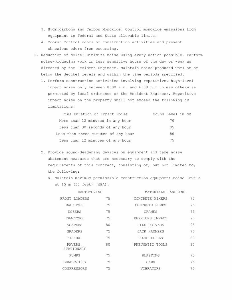
3. Hydrocarbons and Carbon Monoxide: Control monoxide emissions from
equipment to Federal and State allowable limits.
4. Odors: Control odors of construction activities and prevent
obnoxious odors from occurring.
F. Reduction of Noise: Minimize noise using every action possible. Perform
noise-producing work in less sensitive hours of the day or week as
directed by the Resident Engineer. Maintain noise-produced work at or
below the decibel levels and within the time periods specified.
1. Perform construction activities involving repetitive, high-level
impact noise only between 8:00 a.m. and 6:00 p.m unless otherwise
permitted by local ordinance or the Resident Engineer. Repetitive
impact noise on the property shall not exceed the following dB
limitations:
Time Duration of Impact Noise Sound Level in dB
More than 12 minutes in any hour 70
Less than 30 seconds of any hour 85
Less than three minutes of any hour 80
Less than 12 minutes of any hour 75
2. Provide sound-deadening devices on equipment and take noise
abatement measures that are necessary to comply with the
requirements of this contract, consisting of, but not limited to,
the following:
a. Maintain maximum permissible construction equipment noise levels
at 15 m (50 feet) (dBA):
EARTHMOVING MATERIALS HANDLING
FRONT LOADERS 75 CONCRETE MIXERS 75
BACKHOES 75 CONCRETE PUMPS 75
DOZERS 75 CRANES 75
TRACTORS 75 DERRICKS IMPACT 75
SCAPERS 80 PILE DRIVERS 95
GRADERS 75 JACK HAMMERS 75
TRUCKS 75 ROCK DRILLS 80
PAVERS, STATIONARY
80 PNEUMATIC TOOLS 80
PUMPS 75 BLASTING 75
GENERATORS 75 SAWS 75
COMPRESSORS 75 VIBRATORS 75

b. Use shields or other physical barriers to restrict noise
transmission.
c. Provide soundproof housings or enclosures for noise-producing
machinery.
d. Use efficient silencers on equipment air intakes.
e. Use efficient intake and exhaust mufflers on internal combustion
engines that are maintained so equipment performs below noise
levels specified.
f. Line hoppers and storage bins with sound deadening material.
g. Conduct truck loading, unloading, and hauling operations so that
noise is kept to a minimum.
3. Measure sound level for noise exposure due to the construction at
least once every five successive working days while work is being
performed above 55 dB(A) noise level. Measure noise exposure at the
property line or 15 m (50 feet) from the noise source, whichever is
greater. Measure the sound levels on the A weighing network of a
General Purpose sound level meter at slow response. To minimize the
effect of reflective sound waves at buildings, take measurements at
900 to 1800 mm (three to six feet) in front of any building face.
Submit the recorded information to the Resident Engineer noting any
problems and the alternatives for mitigating actions.
G. Restoration of Damaged Property: If any direct or indirect damage is
done to public or private property resulting from any act, omission,
neglect, or misconduct, the Contractor shall restore the damaged
property to a condition equal to that existing before the damage at no
additional cost to the Government. Repair, rebuild, or restore property
as directed or make good such damage in an acceptable manner.
H. Final Clean-up: On completion of project and after removal of all
debris, rubbish, and temporary construction, Contractor shall leave the
construction area in a clean condition satisfactory to the Resident
Engineer. Cleaning shall include off the station disposal of all items
and materials not required to be salvaged, as well as all debris and
rubbish resulting from demolition and new work operations.
- - - E N D - - -

SECTION 01 74 19 CONSTRUCTION WASTE MANAGEMENT
PART 1 – GENERAL
1.1 DESCRIPTION
A. This section specifies the requirements for the management of non-
hazardous building construction and demolition waste.
B. Waste disposal in landfills shall be minimized to the greatest extent
possible. Of the inevitable waste that is generated, as much of the
waste material as economically feasible shall be salvaged, recycled or
reused.
C. Contractor shall use all reasonable means to divert construction and
demolition waste from landfills and incinerators, and facilitate their
salvage and recycle not limited to the following:
1. Waste Management Plan development and implementation.
2. Techniques to minimize waste generation.
3. Sorting and separating of waste materials.
4. Salvage of existing materials and items for reuse or resale.
5. Recycling of materials that cannot be reused or sold.
D. At a minimum the following waste categories shall be diverted from
landfills:
1. Inerts (eg, concrete, masonry and asphalt).
2. Clean dimensional wood and palette wood.
3. Green waste (biodegradable landscaping materials).
4. Engineered wood products (plywood, particle board and I-joists,
etc).
5. Metal products (eg, steel, wire, beverage containers, copper, etc).
6. Cardboard, paper and packaging.
7. Plastics (eg, ABS, PVC).
8. Carpet and/or pad.
9. Gypsum board.
10. Insulation.
11. Paint.
12. Fluorescent lamps.
1.2 RELATED WORK
A. Section 02 41 00, DEMOLITION.
B. Section 01 00 00, GENERAL REQUIREMENTS.

1.3 QUALITY ASSURANCE
A. Contractor shall practice efficient waste management when sizing,
cutting and installing building products. Processes shall be employed
to ensure the generation of as little waste as possible. Construction
/Demolition waste includes products of the following:
1. Excess or unusable construction materials.
2. Packaging used for construction products.
3. Poor planning and/or layout.
4. Construction error.
5. Over ordering.
6. Weather damage.
7. Contamination.
8. Mishandling/breakage.
B. Establish and maintain the management of non-hazardous building
construction and demolition waste set forth herein. Conduct a site
assessment to estimate the types of materials that will be generated by
demolition and construction.
C. Contractor shall develop and implement procedures to reuse and recycle
new materials to a minimum of 50 percent.
D. Contractor shall be responsible for implementation of any special
programs involving rebates or similar incentives related to recycling.
Any revenues or savings obtained from salvage or recycling shall accrue
to the contractor.
E. Contractor shall provide all demolition, removal and legal disposal of
materials. Contractor shall ensure that facilities used for recycling,
reuse and disposal shall be permitted for the intended use to the
extent required by local, state, federal regulations. The Whole
Building Design Guide website http://www.wbdg.org provides a
Construction Waste Management Database that contains information on
companies that haul, collect, and process recyclable debris from
construction projects.
F. Contractor shall assign a specific area to facilitate separation of
materials for reuse, salvage, recycling, and return. Such areas are to
be kept neat and clean and clearly marked in order to avoid
contamination or mixing of materials.
G. Contractor shall provide on-site instructions and supervision of
separation, handling, salvaging, recycling, reuse and return methods to
be used by all parties during waste generating stages.

H. Record on daily reports any problems in complying with laws,
regulations and ordinances with corrective action taken.
1.4 TERMINOLOGY
A. Class III Landfill: A landfill that accepts non-hazardous resources
such as household, commercial and industrial waste resulting from
construction, remodeling, repair and demolition operations.
B. Clean: Untreated and unpainted; uncontaminated with adhesives, oils,
solvents, mastics and like products.
C. Construction and Demolition Waste: Includes all non-hazardous resources
resulting from construction, remodeling, alterations, repair and
demolition operations.
D. Dismantle: The process of parting out a building in such a way as to
preserve the usefulness of its materials and components.
E. Disposal: Acceptance of solid wastes at a legally operating facility
for the purpose of land filling (includes Class III landfills and inert
fills).
F. Inert Backfill Site: A location, other than inert fill or other
disposal facility, to which inert materials are taken for the purpose
of filling an excavation, shoring or other soil engineering operation.
G. Inert Fill: A facility that can legally accept inert waste, such as
asphalt and concrete exclusively for the purpose of disposal.
H. Inert Solids/Inert Waste: Non-liquid solid resources including, but not
limited to, soil and concrete that does not contain hazardous waste or
soluble pollutants at concentrations in excess of water-quality
objectives established by a regional water board, and does not contain
significant quantities of decomposable solid resources.
I. Mixed Debris: Loads that include commingled recyclable and non-
recyclable materials generated at the construction site.
J. Mixed Debris Recycling Facility: A solid resource processing facility
that accepts loads of mixed construction and demolition debris for the
purpose of recovering re-usable and recyclable materials and disposing
non-recyclable materials.
K. Permitted Waste Hauler: A company that holds a valid permit to collect
and transport solid wastes from individuals or businesses for the
purpose of recycling or disposal.
L. Recycling: The process of sorting, cleansing, treating, and
reconstituting materials for the purpose of using the altered form in

the manufacture of a new product. Recycling does not include burning,
incinerating or thermally destroying solid waste.
1. On-site Recycling – Materials that are sorted and processed on site
for use in an altered state in the work, i.e. concrete crushed for
use as a sub-base in paving.
2. Off-site Recycling – Materials hauled to a location and used in an
altered form in the manufacture of new products.
M. Recycling Facility: An operation that can legally accept materials for
the purpose of processing the materials into an altered form for the
manufacture of new products. Depending on the types of materials
accepted and operating procedures, a recycling facility may or may not
be required to have a solid waste facilities permit or be regulated by
the local enforcement agency.
N. Reuse: Materials that are recovered for use in the same form, on-site
or off-site.
O. Return: To give back reusable items or unused products to vendors for
credit.
P. Salvage: To remove waste materials from the site for resale or re-use
by a third party.
Q. Source-Separated Materials: Materials that are sorted by type at the
site for the purpose of reuse and recycling.
R. Solid Waste: Materials that have been designated as non-recyclable and
are discarded for the purposes of disposal.
S. Transfer Station: A facility that can legally accept solid waste for
the purpose of temporarily storing the materials for re-loading onto
other trucks and transporting them to a landfill for disposal, or
recovering some materials for re-use or recycling.
1.5 SUBMITTALS
A. In accordance with Section 01 33 23, SHOP DRAWINGS, PRODUCT DATA, and
SAMPLES, furnish the following:
B. Prepare and submit to the COR a written demolition debris management
plan. The plan shall include, but not be limited to, the following
information:
1. Procedures to be used for debris management.
2. Techniques to be used to minimize waste generation.
3. Analysis of the estimated job site waste to be generated:
a. List of each material and quantity to be salvaged, reused,
recycled.

b. List of each material and quantity proposed to be taken to a
landfill.
4. Detailed description of the Means/Methods to be used for material
handling.
a. On site: Material separation, storage, protection where
applicable.
b. Off site: Transportation means and destination. Include list of
materials.
1) Description of materials to be site-separated and self-hauled
to designated facilities.
2) Description of mixed materials to be collected by designated
waste haulers and removed from the site.
c. The names and locations of mixed debris reuse and recycling
facilities or sites.
d. The names and locations of trash disposal landfill facilities or
sites.
e. Documentation that the facilities or sites are approved to
receive the materials.
C. Designated Manager responsible for instructing personnel, supervising,
documenting and administer over meetings relevant to the Waste
Management Plan.
D. Monthly summary of construction and demolition debris diversion and
disposal, quantifying all materials generated at the work site and
disposed of or diverted from disposal through recycling.
1.6 APPLICABLE PUBLICATIONS
A Publications listed below form a part of this specification to the
extent referenced. Publications are referenced by the basic designation
only. In the event that criteria requirements conflict, the most
stringent requirements shall be met.
B. U.S. Green Building Council (USGBC):
LEED Green Building Rating System for New Construction
1.7 RECORDS
Maintain records to document the quantity of waste generated; the
quantity of waste diverted through sale, reuse, or recycling; and the
quantity of waste disposed by landfill or incineration. Records shall
be kept in accordance with the LEED Reference Guide and LEED Template.
PART 2 - PRODUCTS

2.1 MATERIALS
A. List of each material and quantity to be salvaged, recycled, reused.
B. List of each material and quantity proposed to be taken to a landfill.
C. Material tracking data: Receiving parties, dates removed,
transportation costs, weight tickets, tipping fees, manifests,
invoices, net total costs or savings.
PART 3 - EXECUTION
3.1 COLLECTION
A. Provide all necessary containers, bins and storage areas to facilitate
effective waste management.
B. Clearly identify containers, bins and storage areas so that recyclable
materials are separated from trash and can be transported to respective
recycling facility for processing.
C. Hazardous wastes shall be separated, stored, disposed of according to
local, state, federal regulations.
3.2 DISPOSAL
A. Contractor shall be responsible for transporting and disposing of
materials that cannot be delivered to a source-separated or mixed
materials recycling facility to a transfer station or disposal facility
that can accept the materials in accordance with state and federal
regulations.
B. Construction or demolition materials with no practical reuse or that
cannot be salvaged or recycled shall be disposed of at a landfill or
incinerator.
3.3 REPORT
A. With each application for progress payment, submit a summary of
construction and demolition debris diversion and disposal including
beginning and ending dates of period covered.
B. Quantify all materials diverted from landfill disposal through salvage
or recycling during the period with the receiving parties, dates
removed, transportation costs, weight tickets, manifests, invoices.
Include the net total costs or savings for each salvaged or recycled
material.
C. Quantify all materials disposed of during the period with the receiving
parties, dates removed, transportation costs, weight tickets, tipping
fees, manifests, invoices. Include the net total costs for each
disposal.
- - - END OF SECTION 01 74 19 - - -
SECTION 01 81 13 SUSTAINABLE CONSTRUCTION REQUIREMENTS
PART 1 - GENERAL
1.1 DESCRIPTION
This Section describes general requirements and procedures to comply with
federal mandates and U.S. Department of Veterans Affairs (VA) policies
for sustainable construction.
The Design Professional has selected materials and utilized integrated
design processes that achieve the Government’s objectives. Contractor
is responsible to maintain and support these objectives in developing
means and methods for performing work and in proposing product
substitutions or changes to specified processes. Obtain approval from
Contracting Officer for all changes and substitutions to materials or
processes. Proposed changes must meet, or exceed, materials or
processes specified.
1.1 RELATED WORK
Section 01 57 19 TEMPORARY ENVIRONMENTAL CONTROLS.
Section 01 74 19 CONSTRUCTION WASTE MANANGEMENT.
1.2 DEFINITIONS
Recycled Content: Recycled content of materials is defined according to
Federal Trade Commission Guides for the Use of Environmental Marketing
Claims (16 CFR Part 260). Recycled content value of a material assembly
is determined by weight. Recycled fraction of assembly is multiplied by
cost of assembly to determine recycled content value.
“Post-Consumer” material is defined as waste material generated by
households or by commercial, industrial, and institutional
facilities in their role as end users of the product, which can no
longer be used for its intended purpose.
“Pre-Consumer” material is defined as material diverted from waste
stream during the manufacturing process. Excluded is reutilization
of materials such as rework, regrind, or scrap generated in a
process and capable of being reclaimed within the same process that
generated it.
Biobased Products: Biobased products are derived from plants and other
renewable agricultural, marine, and forestry materials and provide an
alternative to conventional petroleum derived products. Biobased
products include diverse categories such as lubricants, cleaning
products, inks, fertilizers, and bioplastics.

Low Pollutant-Emitting Materials: Materials and products which are
minimally odorous, irritating, or harmful to comfort and well-being of
installers and occupants.
Volatile Organic Compounds (VOC): Chemicals that are emitted as gases from
certain solids or liquids. VOCs include a variety of chemicals, some of
which may have short- and long-term adverse health effects.
1.3 REFERENCE STANDARDS
Carpet and Rug Institute Green Label Plus program.
U.S. Department of Agriculture BioPreferred program (USDA BioPreferred).
U.S. Environmental Protection Agency Comprehensive Procurement Guidelines
(CPG).
U.S. Environmental Protection Agency WaterSense Program (WaterSense).
U.S. Environmental Protection Agency ENERGY STAR Program (ENERGY STAR).
U. S. Department of Energy Federal Energy Management Program (FEMP).
Green Electronic Council EPEAT Program (EPEAT).
1.4 SUBMITTALS
All submittals to be provided by contractor to COR.
Sustainability Action Plan:
Submit documentation as required by this section; provide additional
copies of typical submittals required under technical sections when
sustainable construction requires copies of record submittals.
Within 30 days after Preconstruction Meeting provide a narrative plan
for complying with requirements stipulated within this section.
Sustainability Action Plan must:
Make reference to sustainable construction submittals defined by
this section.
Address all items listed under PERFORMANCE CRITERIA.
Indicate individual(s) responsible for implementing the plan.
Low Pollutant-Emitting Materials Tracking Spreadsheet: Within 30 days
after Preconstruction Meeting provide a preliminary Low Pollutant-
Emitting Materials Tracking Spreadsheet. The Low Pollutant-Emitting
Materials Tracking Spreadsheet must be an electronic file and include
all materials on Project in categories described under Low Pollutant-
Emitting Materials in 01 81 13.
Construction Indoor Air Quality (IAQ) Management Plan:
Not more than 30 days after Preconstruction Meeting provide a
Construction IAQ Management Plan as an electronic file including
descriptions of the following:
Instruction procedures for meeting or exceeding minimum requirements
of ANSI/SMACNA 008-2008, Chapter 3, including procedures for HVAC
Protection, Source Control, Pathway Interruption, Housekeeping,
and Scheduling.
Instruction procedures for protecting absorptive materials stored
on-site or installed from moisture damage.
Schedule of submission of photographs of on-site construction IAQ
management measures such as protection of ducts and on-site
stored oil installed absorptive materials.
Instruction procedures if air handlers must be used during
construction, including a description of filtration media to be
used at each return air grille.
Instruction procedure for replacing all air-filtration media
immediately prior to occupancy after completion of construction,
including a description of filtration media to be used at each
air handling or air supply unit.
Instruction procedures and schedule for implementing building flush-
out.
Product Submittals:
Recycled Content: Submit product data from manufacturer indicating
percentages by weight of post-consumer and pre-consumer recycled
content for products having recycled content (excluding MEP systems
equipment and components).
Biobased Content: Submit product data for products to be installed or
used which are included in any of the USDA BioPreferred program’s
product categories. Data to include percentage of biobased content
and source of biobased material.
Low Pollutant-Emitting Materials: Submit product data confirming
compliance with relevant requirements for all materials on Project
in categories described under Low Pollutant-Emitting Materials in 01
81 13.
For applicable products and equipment, submit product documentation
confirming ENERGY STAR label, FEMP certification, WaterSense, and/or
EPEAT certification.

Sustainable Construction Progress Reports: Concurrent with each
Application for Payment, submit a Sustainable Construction Progress
Report to confirm adherence with Sustainability Action Plan.
Include narratives of revised strategies for bringing work progress
into compliance with plan and product submittal data.
Include updated and current Low Pollutant-Emitting Materials Tracking
Spreadsheet.
Include construction waste tracking, in tons or cubic yards, including
waste description, whether diverted or landfilled, hauler, and
percent diverted for comingled quantities; and excluding land-
clearing debris and soil. Provide haul receipts and documentation of
diverted percentages for comingled wastes.
Closeout Submittals: Within 14 days after Substantial Completion provide
the following:
Final version of Low Pollutant-Emitting Materials Tracking Spreadsheet.
Manufacturer’s cut sheets and product data highlighting the Minimum
Efficiency Reporting Value (MERV) for filtration media installed at
return air grilles during construction if permanently installed air
handling units are used during construction.
Manufacturer’s cut sheets and product data highlighting the Minimum
Efficiency Reporting Value (MERV) for final filtration media in air
handling units.
Minimum 18 construction photographs including six photographs taken on
three different occasions during construction of ANSI/SMACNA 008-
2008, Chapter 3 approaches employed, along with a brief description
of each approach, documenting implementation of IAQ management
measures, such as protection of ducts and on-site stored or
installed absorptive materials.
Flush-out Documentation:
Product data for filtration media used during flush-out.
Product data for filtration media installed immediately prior to
occupancy.
Signed statement describing building air flush-out procedures
including dates when flush-out was begun and completed and
statement that filtration media was replaced after flush-out.
1.5 QUALITY ASSURANCE

Preconstruction Meeting: After award of Contract and prior to commencement
of Work, schedule and conduct meeting with COR/Resident Engineer and
Architect to discuss the Project Sustainable Action Plan content as it
applies to submittals, project delivery, required Construction Indoor
Air Quality (IAQ) Management Plan, and other Sustainable Construction
Requirements. The purpose of this meeting is to develop a mutual
understanding of the Sustainable Construction Requirements and
coordination of contractor’s management of these requirements with the
Contracting Officer and the Construction Quality Manager.
Construction Job Conferences: Status of compliance with Sustainable
Construction Requirements of these specifications will be an agenda
item at regular job meetings conducted during the course of work at the
site.
1.7 APPLICABLE PUBLICATIONS
A. Publications listed below form a part of this specification to extent
referenced. Publications are referenced in text by basic designation
only. Comply with applicable provisions and recommendations of the
following, except as otherwise shown or specified.
B. Green Seal Standard GS-11, Paints, 1st Edition, May 20, 1993.
C. Green Seal Standard GC-03, Anti-Corrosive Paints, 2nd Edition, January
7, 1997.
D. Green Seal Standard GC-36, Commercial Adhesives, October 19, 2000.
E. South Coast Air Quality Management District (SCAQMD) Rule 1113,
Architectural Coatings, rules in effect on January 1, 2004.
F. South Coast Air Quality Management District (SCAQMD) Rule 1168, July 1,
2005 and rule amendment date of January 7, 2005.
G. Sheet Metal and Air Conditioning National Contractors’ Association
(SMACNA) IAQ Guidelines for Occupied Buildings under Construction, 2nd
Edition (ANSI/SMACNA 008-2008), Chapter 3.
H. California Department of Public Health Standard Method for the Testing
and Evaluation of Volatile Organic Chemical Emissions from Indoor
Sources Using Environmental Chambers, Version 1.1, Emission Testing
method for California Specification 01350 (CDPH Standard Method V1.1-
2010).
I. Federal Trade Commission Guides for the Use of Environmental Marketing
Claims (16 CFR Part 260).
J. ASHRAE Standard 52.2-2007.

PART 2 – PRODUCTS
2.1 PERFORMANCE CRITERIA
A. Construction waste diversion from landfill disposal must comprise at
least 50 percent of total construction waste, excluding land clearing
debris and soil. Alternative daily cover (ADC) does not qualify as
material diverted from disposal.
B. Low Pollutant-Emitting Materials:

Adhesives, sealants and sealant primers applied on site within the
weatherproofing membrane must comply with VOC limits of SCAQMD Rule
1168:
Flooring Adhesives and Sealants:
Indoor carpet adhesives: 50 g/L.
Wood Flooring Adhesive: 100 g/L.
Rubber Floor Adhesives: 60 g/L.
Subfloor Adhesives: 50 g/L.
Ceramic Tile Adhesives and Grout: 65 g/L.
Cove Base Adhesives: 50 g/L.
Multipurpose Construction Adhesives: 70 g/L.
Porous Material (Except Wood) Substrate: 50 g/L.
Wood Substrate: 30 g/L.
Architectural Non-Porous Sealant Primer: 250 g/L.
Architectural Porous Sealant Primer: 775 g/L.
Other Sealant Primer: 750 g/L.
Structural Wood Member Adhesive: 140 g/L.
Sheet-Applied Rubber Lining Operations: 850 g/L.
Top and Trim Adhesive: 250 g/L.
Architectural Sealant: 250 g/L.
Other Sealant: 420 g/L.
Non-Flooring Adhesives and Sealants:
Drywall and Panel Adhesives: 50 g/L.
Multipurpose Construction Adhesives: 70 g/L.
Structural Glazing Adhesives: 100 g/L.
Metal-to-Metal Substrate Adhesives: 30 g/L.
Plastic Foam Substrate Adhesive: 50 g/L.
Porous Material (Except Wood) Substrate Adhesive: 50 g/L.
Wood Substrate Adhesive: 30 g/L.
Fiberglass Substrate Adhesive: 80 g/L.
Architectural Non-Porous Sealant Primer: 250 g/L.
Architectural Porous Sealant Primer: 775 g/L.
Other Sealant Primer: 750 g/L.
PVC Welding Adhesives: 510 g/L.
CPVC Welding Adhesives: 490 g/L.
ABS Welding Adhesives: 325 g/L.
Plastic Cement Welding Adhesives: 250 g/L.
Adhesive Primer for Plastic: 550 g/L.

Contact Adhesive: 80 g/L.
Special Purpose Contact Adhesive: 250 g/L.
Structural Wood Member Adhesive: 140 g/L.
Sheet Applied Rubber Lining Operations: 850 g/L.
Top and Trim Adhesive: 250 g/L.
Architectural Sealants: 250 g/L.
Other Sealants: 420 g/L.
Aerosol adhesives applied on site within the weatherproofing membrane
must comply with the following Green Seal GS-36.
Aerosol Adhesive, General-Purpose Mist Spray: 65 percent VOCs by
weight.
Aerosol Adhesive, General-Purpose Web Spray: 55 percent VOCs by
weight.
Special-Purpose Aerosol Adhesive (All Types): 70 percent VOCs by
weight.
Paints and coatings applied on site within the weatherproofing membrane
must comply with the following criteria:
VOC content limits for paints and coatings established in Green Seal
Standard GS-11.
VOC content limit for anti-corrosive and anti-rust paints applied to
interior ferrous metal substrates of 250 g/L established in Green
Seal GC-03.
Clear wood finishes, floor coatings, stains, primers, sealers, and
shellacs applied to interior elements must not exceed VOC content
limits established in SCAQMD Rule 1113.
Comply with the following VOC content limits:
Anti-Corrosive/Antirust Paints: 250 g/L.
Clear Wood Finish, Lacquer: 550 g/L.
Clear Wood Finish, Sanding Sealer: 350 g/L.
Clear Wood Finish, Varnish: 350 g/L.
Floor Coating: 100 g/L.
Interior Flat Paint, Coating or Primer: 50 g/L.
Interior Non-Flat Paint, Coating or Primer: 150 g/L.
Sealers and Undercoaters: 200 g/L.
Shellac, Clear: 730 g/L.
Shellac, Pigmented: 550 g/L.
Stain: 250 g/L.
Clear Brushing Lacquer: 680 g/L.

Concrete Curing Compounds: 350 g/L.
Japans/Faux Finishing Coatings: 350 g/L.
Magnesite Cement Coatings: 450 g/L.
Pigmented Lacquer: 550 g/L.
Waterproofing Sealers: 250 g/L.
Wood Preservatives: 350 g/L.
Low-Solids Coatings: 120 g/L.
Carpet installed in building interior must comply with one of the
following:
Meet testing and product requirements of the Carpet and Rug
Institute Green Label Plus program.
Maximum VOC concentrations specified in CDPH Standard Method V1.1-
2010, using office scenario at the 14 day time point.
Each non-carpet flooring element installed in building interior which
is not inherently non-emitting (stone, ceramic, powder-coated
metals, plated or anodized metal, glass, concrete, clay brick, and
unfinished or untreated solid wood flooring) must comply with one of
the following:
Meet requirements of the FloorScore standard as shown with testing
by an independent third-party.
Maximum VOC concentrations specified in CDPH Standard Method V1.1-
2010, using office scenario at 14 day time point.
Composite wood and agrifiber products used within the weatherproofing
membrane must contain no added urea-formaldehyde resins.
Laminating adhesives used to fabricate on-site and shop-applied
composite wood and agrifiber assemblies must not contain added urea-
formaldehyde.
Recycled Content:
Any products being installed or used that are listed on EPA
Comprehensive Procurement Guidelines designated product list must
meet or exceed the EPA’s recycled content recommendations. The EPA
Comprehensive Procurement Guidelines categories include:
Building insulation.
Cement and concrete.
Consolidated and reprocessed latex paint.
Floor tiles.
Flowable fill.
Laminated paperboard.

Modular threshold ramps.
Nonpressure pipe.
Patio blocks.
Railroad grade crossing surfaces.
Roofing materials.
Shower and restroom dividers/partitions.
Structural fiberboard.
Nylon carpet and nylon carpet backing.
Compost and fertilizer made from recovered organic materials.
Hydraulic mulch.
Lawn and garden edging.
Plastic lumber landscaping timbers and posts.
Park benches and picnic tables.
Plastic fencing.
Playground equipment.
Playground surfaces.
Bike racks.
Biobased Content:
Materials and equipment being installed or used that are listed on the
USDA BioPreferred program product category list must meet or exceed
USDA’s minimum biobased content threshold. Refer to individual
specification sections for detailed requirements applicable to that
section.
USDA BioPreferred program categories include:
Adhesive and Mastic Removers.
Carpets.
Cleaners.
Composite Panels.
Corrosion Preventatives.
Erosion Control Materials.
Dust Suppressants.
Fertilizers.
Floor Cleaners and Protectors.
Floor Coverings (Non-Carpet).
Glass Cleaners.
Hydraulic Fluids.
Industrial Cleaners.
Interior Paints and Coatings.

Mulch and Compost Materials.
Multipurpose Cleaners.
Multipurpose Lubricants.
Packaging Films.
Paint Removers.
Plastic Insulating Foam.
Pneumatic Equipment Lubricants.
Roof Coatings.
Wastewater Systems Coatings.
Water Tank Coatings.
Wood and Concrete Sealers.
Wood and Concrete Stains.
Materials, products, and equipment being installed which fall into a
category covered by the WaterSense program must be WaterSense-labeled
or meet or exceed WaterSense program performance requirements, unless
disallowed for infection control reasons.
WaterSense categories include:
Bathroom Faucets
Commercial Toilets
Irrigation Controllers
Pre-Rinse Spray Valves
Residential Toilets
Showerheads
Spray Sprinkler Bodies
Urinals
Materials, products, and equipment being installed which fall into any of
the following product categories must be Energy Star-labeled.
Applicable Energy Star product categories as of 09/14/2017 include:
Appliances:
Air Purifiers and Cleaners.
Clothes Dryers (Residential).
Clothes Washers (Commercial & Residential).
Dehumidifiers.
Dishwashers (Residential).
Freezers (Residential).
Refrigerators (Residential).
Electronics and Information Technology:
Audio/Video Equipment.

Computers.
Data Center Storage.
Digital Media Player.
Enterprise Servers.
Imaging Equipment.
Monitors.
Professional Displays.
Set-Top and Cable Boxes.
Telephones.
Televisions.
Uninterruptible Power Supplies.
Voice over Internet Protocol (VoIP) Phones.
Food Service Equipment (Commercial):
Dishwashers.
Fryers.
Griddles.
Hot Food Holding Cabinets.
Ice Makers.
Ovens.
Refrigerators and Freezers.
Steam Cookers.
Vending Machines.
Heating and Cooling Equipment:
Air-Source Heat Pumps (Residential).
Boilers.
Ceiling Fans (Residential).
Central Air Conditioners (Residential).
Ductless Heating and Cooling (Residential).
Furnaces (Residential).
Water Heaters.
Geothermal Heat Pumps (Residential).
Light Commercial Heating and Cooling Equipment.
Room Air Conditioners (Residential).
Ventilation Fans (Residential).
Other:
Decorative Light Strings.
Electric Vehicle Supply Equipment.
Laboratory-Grade Refrigerators and Freezers.

Light Bulbs.
Light Fixtures.
Pool Pumps.
Roof Products.
Water Coolers.
Windows, Doors, and Skylights.
Materials, products, and equipment being installed which fall into any of
the following categories must be FEMP-designated. FEMP-designated
product categories as of 09/14/2017 include:
Boilers (Commercial).
Dishwashers (Commercial).
Electric Chillers, Air-Cooled (Commercial).
Electric Chillers, Water-Cooled (Commercial).
Exterior Lighting.
Fluorescent Ballasts.
Fluorescent Lamps, General Service.
Ice Machines, Water-Cooled.
Industrial Lighting (High/Low Bay).
Light Emitting Diode (LED) Luminaires.
Electronic products and equipment being installed which fall into any of
the following categories shall be EPEAT registered. Electronic products
and equipment covered by EPEAT program as of 09/14/2017 include:
Computers.
Displays.
Imaging Equipment.
Televisions.
PART 3 - EXECUTION
3.1 FIELD QUALITY CONTROL
A. Construction Indoor Air Quality Management:
1. During construction, meet or exceed recommended control measures of
ANSI/SMACNA 008-2008, Chapter 3.
Protect stored on-site and installed absorptive materials from moisture
damage.
If permanently installed air handlers are used during construction,
filtration media with a minimum efficiency reporting value (MERV) of
8 must be used at each return air grille, as determined by ASHRAE
Standard 52.2-1999 (with errata but without addenda). Replace all
filtration media immediately prior to occupancy.
Perform building flush-out as follows:
After construction ends, prior to occupancy and with interior
finishes installed, perform a building flush-out by supplying a
total volume of 14000 cu. ft. of outdoor air per sq. ft. of floor
area while maintaining an internal temperature of at least 60
degrees Fahrenheit and a relative humidity no higher than 60
percent. OR
If occupancy is desired prior to flush-out completion, the space may
be occupied following delivery of a minimum of 3500 cu. ft. of
outdoor air per sq. ft. of floor area to the space. Once a space
is occupied, it must be ventilated at a minimum rate of 0.30 cfm
per sq. ft. of outside air or design minimum outside air rate
determined until a total of 14000 cu. ft./sq. ft. of outside air
has been delivered to the space. During each day of flush-out
period, ventilation must begin a minimum of three hours prior to
occupancy and continue during occupancy.
-----END----

SECTION 02 41 00 DEMOLITION
PART 1 - GENERAL
1.1 DESCRIPTION:
This section specifies demolition and removal of portions of buildings.
1.2 RELATED WORK:
A. Safety Requirements: GENERAL CONDITIONS Article, ACCIDENT PREVENTION.
1.3 PROTECTION:
A. Perform demolition in such manner as to eliminate hazards to persons
and property; to minimize interference with use of adjacent areas,
utilities and structures or interruption of use of such utilities; and
to provide free passage to and from such adjacent areas of structures.
Comply with requirements of GENERAL CONDITIONS Article, ACCIDENT
PREVENTION.
B. Provide safeguards, including warning signs, barricades, temporary
fences, warning lights, and other similar items that are required for
protection of all personnel during demolition and removal operations.
C. Provide enclosed dust chutes with control gates from each floor to
carry debris to truck beds and govern flow of material into truck.
Provide overhead bridges of tight board or prefabricated metal
construction at dust chutes to protect persons and property from
falling debris.
E. Prevent spread of flying particles and dust. Sprinkle rubbish and
debris with water to keep dust to a minimum. Do not use water if it
results in hazardous or objectionable condition such as, but not
limited to; ice, flooding, or pollution. Vacuum and dust the work area
daily.
F. In addition to previously listed fire and safety rules to be observed
in performance of work, include following:
1. Wherever a cutting torch or other equipment that might cause a fire
is used, provide and maintain fire extinguishers nearby ready for
immediate use. Instruct all possible users in use of fire
extinguishers.
G. Before beginning any demolition work, the Contractor shall survey the
site and examine the drawings and specifications to determine the
extent of the work. The contractor shall take necessary precautions to
avoid damages to existing items to remain in place; any damaged items

shall be repaired or replaced as approved by the Resident Engineer. The
Contractor shall coordinate the work of this section with all other
work and shall construct and maintain shoring, bracing, and supports as
required. The Contractor shall ensure that structural elements are not
overloaded and shall be responsible for increasing structural supports
or adding new supports as may be required as a result of any cutting,
removal, or demolition work performed under this contract. Do not
overload structural elements. Provide new supports and reinforcement
for existing construction weakened by demolition or removal works.
Repairs, reinforcement, or structural replacement must have Resident
Engineer’s approval.
H. The work shall comply with the requirements of Section 01 57 19,
TEMPORARY ENVIRONMENTAL CONTROLS.
I. The work shall comply with the requirements of Section 01 00 00,
GENERAL REQUIREMENTS, Article 1.7 INFECTION PREVENTION MEASURES.
PART 2 - PRODUCTS (NOT USED)
PART 3 – EXECUTION
3.1 DEMOLITION:
A. Completely demolish and remove items as shown, including all
appurtenances related or connected thereto.
B. Debris, including brick, concrete, stone, metals and similar materials
shall become property of Contractor and shall be disposed of by him
daily, off the site to avoid accumulation at the demolition site.
Materials that cannot be removed daily shall be stored in areas
specified by the Resident Engineer. Contractor shall dispose debris in
compliance with applicable federal, state or local permits, rules
and/or regulations.
D. Remove existing utilities as indicated or uncovered by work and
terminate in a manner conforming to the nationally recognized code
covering the specific utility and approved by the Resident Engineer.
When Utility lines are encountered that are not indicated on the
drawings, the Resident Engineer shall be notified prior to further work
in that area.
E. Ceramic Floor Tile: Demolish all tile and setting bed as required for
installation of new setting bed and tile where noted as new tile work.
3.2 CLEAN-UP:
On completion of work of this section and after removal of all debris,
leave site in clean condition satisfactory to Resident Engineer.

Clean-up shall include off the site disposal of all items and materials
not required to remain property of the Government as well as all debris
and rubbish resulting from demolition operations.
- - - E N D - - -

SECTION 02 82 11 TRADITIONAL ASBESTOS ABATEMENT
TABLE OF CONTENTS
1.1 SUMMARY OF THE WORK....................................................i
1.1.1 CONTRACT DOCUMENTS AND RELATED REQUIREMENTS..........................i
1.1.2 EXTENT OF WORK.......................................................ii
1.1.3 RELATED WORK.........................................................ii
1.1.4 TASKS................................................................ii
1.1.5 CONTRACTORS USE OF PREMISES..........................................ii
1.2 VARIATIONS IN QUANTITY.............................................................iii
1.3 STOP ASBESTOS REMOVAL..............................................................iii
1.4 DEFINITIONS............................................................iv
1.4.1 GENERAL..............................................................iv
1.4.2 GLOSSARY.............................................................iv
1.4.3 REFERENCED STANDARDS ORGANIZATIONS...................................x
1.5 APPLICABLE CODES AND REGULATIONS.......................................xi
1.5.1 GENERAL APPLICABILITY OF CODES, REGULATIONS, AND STANDARDS...........xi
1.5.2 Asbestos Abatement CONTRACTOR RESPONSIBILITY.........................xi
1.5.3 FEDERAL REQUIREMENTS.........................................................xii
1.5.4 STATE REQUIREMENTS.........................................................Error! Bookmark not defined.
1.5.5 LOCAL REQUIREMENTS.........................................................Error! Bookmark not defined.
1.5.6 STANDARDS............................................................xii
1.5.7 EPA GUIDANCE DOCUMENTS............................................................xii
1.5.8 NOTICES..............................................................xiii
1.5.9 PERMITS/LICENSES.....................................................xiii
1.5.10 POSTING AND FILING OF REGULATIONS..........................................................xiii
1.5.11 VA RESPONSIBILITIES.....................................................xiii
1.5.12 EMERGENCY ACTION PLAN AND ARRANGEMENTS.........................................................xiii
1.5.13 PRE-CONSTRUCTION MEETING..............................................................xiv
1.6 PROJECT COORDINATION...................................................xv
1.6.1 PERSONNEL............................................................xv
1.7 RESPIRATORY PROTECTION...........................................................xvi
1.7.1 GENERAL - RESPIRATORY PROTECTION PROGRAM..............................................................xvi
1.7.2 RESPIRATORY PROTECTION PROGRAM COORDINATOR..........................................................xvi
1.7.3 SELECTION AND USE OF RESPIRATORS..........................................................xvi
1.7.4 MINIMUM RESPIRATORY PROTECTION...........................................................xvi
1.7.5 MEDICAL WRITTEN OPINION..............................................................xvi
1.7.6 RESPIRATOR FIT TEST.................................................................xvii
1.7.7 RESPIRATOR FIT CHECK................................................................xvii
1.7.8 MAINTENANCE AND CARE OF RESPIRATORS..........................................................xvii
1.7.9 SUPPLIED AIR SYSTEMS..............................................................xvii
1.8 WORKER PROTECTION...........................................................xvii

1.8.1 TRAINING OF ABATEMENT PERSONNEL............................................................xvii
1.8.2 MEDICAL EXAMINATIONS.........................................................xvii
1.8.3 REGULATED AREA ENTRY PROCEDURE............................................................xviii
1.8.4 DECONTAMINATION PROCEDURE............................................................xviii
1.8.5 REGULATED AREA REQUIREMENTS.........................................................xviii
1.9 DECONTAMINATION FACILITIES...........................................................xviii
1.9.1 DESCRIPTION..........................................................xviii
1.9.2 GENERAL REQUIREMENTS.........................................................xix
1.9.3 TEMPORARY FACILITIES TO THE PDF and W/EDF................................................................xix
1.9.4 PERSONNEL DECONTAMINATION FACILITY (PDF)................................................................xix
1.9.5 WASTE/EQUIPMENT DECONTAMINATION FACILITY (W/EDF)..............................................................xxi
1.9.6 WASTE/EQUIPMENT DECONTAMINATION PROCEDURES...........................................................xxii
PART 2 - PRODUCTS, MATERIALS AND EQUIPMENT............................................................xxii
2.1 MATERIALS AND EQUIPMENT............................................................xxii
2.1.1 GENERAL REQUIREMENTS.........................................................xxii
2.2 MONITORING, INSPECTION AND TESTING..............................................................xxiii

2.2.1 GENERAL..............................................................xxiii
2.2.2 SCOPE OF SERVICES OF THE VPIH/CIH CONSULTANT...........................................................xxiv
2.2.3 MONITORING, INSPECTION AND TESTING BY CONTRACTOR CPIH/CIH.............................................................xxv
2.3 ASBESTOS hAZARD aBATEMENT pLAN.................................................................xxvi
2.4 SUBMITTALS...........................................................xxvi
2.4.1 PRE-START MEETING SUBMITTALS...........................................................xxvi
2.4.2 SUBMITTALS DURING ABATEMENT............................................................xxviii
2.4.3 SUBMITTALS AT COMPLETION OF ABATEMENT............................................................xxviii
2.5 ENCAPSULANTS.........................................................xxix
2.5.1 TYPES OF ENCAPSULANTS.........................................................xxix
2.5.2 PERFORMANCE REQUIREMENTS.........................................................xxix
2.5.3 CERTIFICATES OF COMPLIANCE...........................................................xxix
PART 3 - EXECUTION............................................................xxix
3.1 REGULATED AREA PREPARATIONS.........................................................xxix
3.1.3.1 DESIGN AND LAYOUT...............................................................xxxi
3.1.3.2 NEGATIVE AIR MACHINES (HEPA UNITS)...............................................................xxxi

3.1.3.3 PRESSURE DIFFERENTIAL.........................................................xxxiii
3.1.3.4 MONITORING...........................................................xxxiii
3.1.3.5 AUXILIARY GENERATOR............................................................xxxiii
3.1.3.6SUPPLEMENTAL MAKE-UP AIR INLETS...............................................................xxxiii
3.1.3.7 TESTING THE SYSTEM...............................................................xxxiii
3.1.3.8 DEMONSTRATION OF THE NEGATIVE PRESSURE Filtration SYSTEM...............................................................xxxiii
3.1.3.9 USE OF THE NEGATIVE PRESSURE FILTRATION SYSTEM DURING ABATEMENT OPERATIONS...........................................................xxxiv
3.1.3.10 DISMANTLING THE SYSTEM...............................................................xxxiv
3.1.4 CONTAINMENT BARRIERS AND COVERINGS IN THE REGULATED AREA.................................................................xxxv
3.1.4.1 GENERAL..............................................................xxxv
3.1.4.2 PREPARATION PRIOR TO SEALING THE REGULATED AREA.................................................................xxxv
3.1.4.3 CONTROLLING ACCESS TO THE REGULATED AREA.................................................................xxxv
3.1.4.4 CRITICAL BARRIERS.............................................................xxxv
3.1.4.5 PRIMARY BARRIERS.............................................................xxxv
3.1.4.6 SECONDARY BARRIERS.............................................................xxxvi
3.1.4.7 EXTENSION OF THE REGULATED AREA.................................................................xxxvi

3.1.4.8 FIRESTOPPING.........................................................xxxvi
3.1.5 Sanitary facilities...........................................................xxxvi
3.1.6 PERSONAL PROTECTIVE EQUIPMENT............................................................xxxvi
3.1.7 Pre-cleaning.............................................................xxxvii
3.1.8 PRE-ABATEMENT ACTIVITIES...........................................................xxxvii
3.1.8.1 PRE-ABATEMENT Meeting..............................................................xxxvii
3.1.8.2 PRE-ABATEMENT CONSTRUCTION AND OPERATIONS...........................................................xxxviii
3.1.8.3 PRE-ABATEMENT INSPECTIONS AND PREPARATIONS.........................................................xxxviii
3.2 REMOVAL OF ACM..................................................................xxxix
3.2.1 WETTING acm..................................................................xxxix
3.2.2 SECONDARY BARRIER AND WALKWAYS.............................................................xxxix
3.2.3 WET REMOVAL OF ACM..................................................................xxxix
3.2.4 WET REMOVAL OF AMOSITE..............................................................xli
3.2.5 REMOVAL OF ACM/DIRT FLOORS AND OTHER SPECIAL PROCEDURES...........................................................xli
3.3 LOCKDOWN ENCAPSULATION........................................................xlii
3.3.1 GENERAL..............................................................xlii

3.3.2 DELIVERY AND STORAGE..............................................................xlii
3.3.3 WORKER PROTECTION...........................................................xlii
3.3.4 ENCAPSULATION OF SCRATCH COAT PLASTER OR PIPING...............................................................xlii
3.3.5 SEALING EXPOSED EDGES................................................................xliii
3.4 DISPOSAL OF ACM WASTE MATERIALS............................................................xliii
3.4.1 GENERAL..............................................................xliii
3.4.2 PROCEDURES...........................................................xliii
3.5 PROJECT DECONTAMINATION......................................................xliii
3.5.1 GENERAL..............................................................xliii
3.5.2 REGULATED AREA CLEARANCE............................................................xliv
3.5.3 WORK DESCRIPTION..........................................................xliv
3.5.4 PRE-DECONTAMINATION CONDITIONS...........................................................xliv
3.5.5 FIRST CLEANING.............................................................xliv
3.5.6 PRE-CLEARANCE INSPECTION AND TESTING..............................................................xliv
3.5.7 LOCKDOWN ENCAPSULATION OF ABATED SURFACES.............................................................xlv
3.6 FINAL VISUAL INSPECTION AND AIR CLEARANCE TESTING..............................................................xlv

3.6.1 GENERAL..............................................................xlv
3.6.2 FINAL VISUAL INSPECTION...........................................................xlv
3.6.3 FINAL AIR CLEARANCE TESTING..............................................................xlv
3.6.4 FINAL AIR CLEARANCE PROCEDURES...........................................................xlv
3.6.5 CLEARANCE SAMPLING USING PCM – LESS THAN 260LF/160SF:.........................................................xlvi
3.6.8 LABORATORY TESTING OF TEM SAMPLES..............................................................xlvii
3.7 ABATEMENT CLOSEOUT AND CERTIFICATE OF COMPLIANCE...........................................................xlvii
3.7.1 COMPLETION OF ABATEMENT WORK.................................................................xlvii
3.7.2 CERTIFICATE OF COMPLETION BY CONTRACTOR...........................................................xlvii
3.7.3 WORK SHIFTS...............................................................xlviii
3.7.4 RE-INSULATION...........................................................xlviii
ATTACHMENT #1...................................................................xlviii
ATTACHMENT #2..............................................................l
ATTACHMENT #4...................................................................lii


INSTRUCTIONS TO ARCHITECT/ENGINEER AND INDUSTRIAL HYGIENE CONSULTANT
SECTION 02 82 11 CLASS I NEGATIVE PRESSURE ENCLOSURE ASBESTOS ABATEMENT SPECIFICATIONS
1. These specifications provide general guidance to personnel given the
task of designing and executing a Class I negative pressure enclosure asbestos abatement project. Each abatement is a unique situation and therefore must be tailored for that project. This specification incorporates current regulatory requirements and current best abatement practices, procedures and technology. The Architect/Engineer and/or the Industrial Hygiene consultants may provide additional specification additions or deletions to this specification that, in their professional judgment, will ensure a safe and effective approach to a specific abatement project while maintaining compliance with applicable regulations and VA policy. Any changes must be clearly marked on/attached to this document prior to finalization of the specification so that the changes will be adequately considered in the review process by the VA.
2. These specifications are to be used in conjunction with asbestos abatement contractor selection criteria; special instructions package; and general construction provisions.
3. Paragraphs that are not preceded by a number code are indented as instructions to the specifications writer and identified by the notation "Spec Writer Notes". These paragraphs must be deleted from the final document.
4. Within the text of the specifications, there may be optional procedures which the specification writer could include in the final specification. Procedures which are not chosen must be deleted by the specification writer. Optional text is shown by the notation.
5. The specification writer, VPIH/CIH, CPIH/CIH, and A/E must be aware of and read the AEQA 10-95 since it details common errors in specification and contract documents for asbestos project. This would be especially helpful if a survey is being conducted prior to an abatement project. A full AHERA survey of the facility would be needed prior to renovation activities, however, if demolition of the facility is planned, a NESHAP survey of the facility would need to be performed.
PART 1 - GENERAL
1.1 SUMMARY OF THE WORK
1.1.1 CONTRACT DOCUMENTS AND RELATED REQUIREMENTS
Drawings, general provisions of the contract, including general and supplementary conditions and other Division 01 specifications, shall apply to the work of this section. The contract documents show the work to be done under the contract and related requirements and conditions impacting the project. Related requirements and conditions include applicable codes and regulations, notices and permits, existing site conditions and restrictions on use of the site, requirements for partial owner occupancy during the work, coordination with other work and the phasing of the work. In the event the Asbestos Abatement Contractor discovers a conflict in the contract documents and/or requirements or codes, the conflict must be brought to the immediate attention of the Contracting Officer for resolution. Whenever there is a conflict or overlap in the requirements, the most stringent shall apply. Any actions

taken by the Contractor without obtaining guidance from the Contracting Officer shall become the sole risk and responsibility of the Asbestos Abatement Contractor. All costs incurred due to such action are also the responsibility of the Asbestos Abatement Contractor.
1.1.2 EXTENT OF WORK
A. Below is a brief description of the estimated quantities of asbestos containing materials to be abated. These quantities are for informational purposes only and are based on the best information available at the time of the specification preparation. The Contractor shall satisfy himself as the actual quantities to be abated. Nothing in this section may be interpreted as limiting the extent of work otherwise required by this contract and related documents.
B. Removal, clean-up and disposal of asbestos containing materials (ACM) and asbestos/waste contaminated elements in an appropriate regulated area.
1.1.3 RELATED WORK
A. Section 07 84 00, FIRESTOPPING. B. Section 02 41 00, DEMOLITION. C. Division 09, FINISHES D. Division 22, PLUMBING. E. Section 21 05 11, COMMON WORK RESULTS FOR FIRE SUPPRESSION / Section 22
05 11, COMMON WORK RESULTS FOR PLUMBING / Section 23 05 11, COMMON WORK RESULTS FOR HVAC AND STEAM GENERATION.
F. Section 21 05 11, COMMON WORK RESULTS FOR FIRE SUPPRESSION / Section 22 05 11, COMMON WORK RESULTS FOR PLUMBING / Section 23 05 11, COMMON WORK RESULTS FOR HVAC AND STEAM GENERATION
G. Section 23 07 11, HVAC INSULATION. H. Section 22 11 00, FACILITY WATER DISTRIBUTION / Section 22 13 00, FACILITY
SANITARY AND VENT PIPING. I. Section 23 31 00, HVAC DUCTS / Section 23 37 00, AIR OUTLETS AND INLETS.
1.1.4 TASKS
The work tasks are summarized briefly as follows: A. Pre-abatement activities including pre-abatement meeting(s),
inspection(s), notifications, permits, submittal approvals, regulated area preparations, emergency procedures arrangements, and standard operating procedures for asbestos abatement work.
B. Abatement activities including removal, encapsulation, enclosure, clean-up and disposal of ACM waste, recordkeeping, security, monitoring, and inspections.
C. Cleaning and decontamination activities including final visual inspection, air monitoring and certification of decontamination.
1.1.5 CONTRACTORS USE OF PREMISES
A. The Contractor and Contractor's personnel shall cooperate fully with the VA representative/consultant to facilitate efficient use of buildings and areas within buildings. The Contractor shall perform the work in accordance with the VA specifications, drawings, phasing plan and in compliance with any/all applicable Federal, State and Local regulations and requirements.
B. The Contractor shall use the existing facilities in the building strictly within the limits indicated in contract documents as well as the approved VA Design and Construction Procedures. VA Design and Construction Procedures drawings of partially occupied buildings will show the limits
of regulated areas; the placement of decontamination facilities; the temporary location of bagged waste ACM; the path of transport to outside the building; and the temporary waste storage area for each building/regulated area. Any variation from the arrangements shown on drawings shall be secured in writing from the VA representative through the pre-abatement plan of action. The following limitations of use shall apply to existing facilities shown on drawings:
1.2 VARIATIONS IN QUANTITY
The quantities and locations of ACM as indicated on the drawings and the extent of work included in this section are estimated which are limited by the physical constraints imposed by occupancy of the buildings and accessibility to ACM. Accordingly, minor variations (+/- 5%) in quantities of ACM within the regulated area are considered as having no impact on contract price and time requirements of this contract. Where additional work is required beyond the above variation, the contractor shall provide unit prices for newly discovered ACM and those prices shall be used for additional work required under the contractor.
1.3 STOP ASBESTOS REMOVAL
If the Contracting Officer; their field representative; (the facility Safety Officer/Manager or their designee, or the VA Professional Industrial Hygienist/Certified Industrial Hygienist (VPIH/CIH) presents a verbal Stop Asbestos Removal Order, the Contractor/Personnel shall immediately stop all asbestos removal and maintain HEPA filtered negative pressure air flow in the containment and adequately wet any exposed ACM. If a verbal Stop Asbestos Removal Order is issued, the VA shall follow-up with a written order to the Contractor as soon as it is practicable. The Contractor shall not resume any asbestos removal activity until authorized to do so in writing by the VA Contracting Officer. A stop asbestos removal order may be issued at any time the VA Contracting Officer determines abatement conditions/activities are not within VA specification, regulatory requirements or that an imminent hazard exists to human health or the environment. Work stoppage will continue until conditions have been corrected to the satisfaction of the VA. Standby time and costs for corrective actions will be borne by the Contractor, including the VPIH/CIH time. The occurrence of any of the following events shall be reported immediately by the Contractor’s competent person to the VA Contracting Office or field representative using the most expeditious means (e.g., verbal or telephonic), followed up with written notification to the Contracting Officer as soon as practical. The Contractor shall immediately stop asbestos removal/disturbance activities and initiate fiber reduction activities:
A. Airborne PCM analysis results equal to or greater than 0.01 f/cc outside a regulated area or >0.05 f/cc inside a regulated area;
B. breach or break in regulated area containment barrier(s); C. less than –0.02” WCG pressure in the regulated area; D. serious injury/death at the site; E. fire/safety emergency at the site; F. respiratory protection system failure; G. power failure or loss of wetting agent; or H. any visible emissions observed outside the regulated area.

1.4 DEFINITIONS
1.4.1 GENERAL
Definitions and explanations here are neither complete nor exclusive of all terms used in the contract documents, but are general for the work to the extent they are not stated more explicitly in another element of the contract documents. Drawings must be recognized as diagrammatic in nature and not completely descriptive of the requirements indicated therein.
1.4.2 GLOSSARY
Abatement - Procedures to control fiber release from asbestos-containing materials. Includes removal, encapsulation, enclosure, demolition, and renovation activities related to asbestos containing materials (ACM).
Aerosol - Solid or liquid particulate suspended in air. Adequately wet - Sufficiently mixed or penetrated with liquid to prevent
the release of particulates. If visible emissions are observed coming from the ACM, then that material has not been adequately wetted.
Aggressive method - Removal or disturbance of building material by sanding, abrading, grinding, or other method that breaks, crumbles, or disintegrates intact ACM.
Aggressive sampling - EPA AHERA defined clearance sampling method using air moving equipment such as fans and leaf blowers to aggressively disturb and maintain in the air residual fibers after abatement.
AHERA - Asbestos Hazard Emergency Response Act. Asbestos regulations for schools issued in 1987.
Aircell - Pipe or duct insulation made of corrugated cardboard which contains asbestos.
Air monitoring - The process of measuring the fiber content of a known volume of air collected over a specified period of time. The NIOSH 7400 Method, Issue 2 is used to determine the fiber levels in air. For personal samples and clearance air testing using Phase Contrast Microscopy (PCM) analysis. NIOSH Method 7402 can be used when it is necessary to confirm fibers counted by PCM as being asbestos. The AHERA TEM analysis may be used for background, area samples and clearance samples when required by this specification, or at the discretion of the VPIH/CIH as appropriate.
Air sample filter - The filter used to collect fibers which are then counted. The filter is made of mixed cellulose ester membrane for PCM (Phase Contrast Microscopy) and polycarbonate for TEM (Transmission Electron Microscopy)
Amended water - Water to which a surfactant (wetting agent) has been added to increase the penetrating ability of the liquid.
Asbestos - Includes chrysotile, amosite, crocidolite, tremolite asbestos, anthophyllite asbestos, actinolite asbestos, and any of these minerals that have been chemically treated or altered. Asbestos also includes PACM, as defined below.
Asbestos Hazard Abatement Plan (AHAP) - Asbestos work procedures required to be submitted by the contractor before work begins.
Asbestos-containing material (ACM) - Any material containing more than one percent of asbestos.
Asbestos contaminated elements (ACE) - Building elements such as ceilings, walls, lights, or ductwork that are contaminated with asbestos.
Asbestos-contaminated soil (ACS) – Soil found in the work area or in adjacent areas such as crawlspaces or pipe tunnels which is contaminated with asbestos-containing material debris and cannot be easily separated from the material.

Asbestos-containing waste (ACW) material - Asbestos-containing material or asbestos contaminated objects requiring disposal.
Asbestos Project Monitor – Some sates require that any person conducting asbestos abatement clearance inspections and clearance air sampling be licensed as an asbestos project monitor.
Asbestos waste decontamination facility - A system consisting of drum/bag washing facilities and a temporary storage area for cleaned containers of asbestos waste. Used as the exit for waste and equipment leaving the regulated area. In an emergency, it may be used to evacuate personnel.
Authorized person - Any person authorized by the VA, the Contractor, or government agency and required by work duties to be present in regulated areas.
Authorized visitor - Any person approved by the VA; the contractor; or any government agency representative having jurisdiction over the regulated area (e.g., OSHA, Federal and State EPA.
Barrier - Any surface the isolates the regulated area and inhibits fiber migration from the regulated area.
Containment Barrier - An airtight barrier consisting of walls, floors, and/or ceilings of sealed plastic sheeting which surrounds and seals the outer perimeter of the regulated area.
Critical Barrier - The barrier responsible for isolating the regulated area from adjacent spaces, typically constructed of plastic sheeting secured in place at openings such as doors, windows, or any other opening into the regulated area.
Primary Barrier – Plastic barriers placed over critical barriers and exposed directly to abatement work.
Secondary Barrier - Any additional plastic barriers used to isolate and provide protection from debris during abatement work.
Breathing zone - The hemisphere forward of the shoulders with a radius of about 150 - 225 mm (6 - 9 inches) from the worker's nose.
Bridging encapsulant - An encapsulant that forms a layer on the surface of the ACM.
Building/facility owner - The legal entity, including a lessee, which exercises control over management and recordkeeping functions relating to a building and/or facility in which asbestos activities take place.
Bulk testing - The collection and analysis of suspect asbestos containing materials.
Certified Industrial Hygienist (CIH) - A person certified in the comprehensive practice of industrial hygiene by the American Board of Industrial Hygiene.
Class I asbestos work - Activities involving the removal of Thermal System Insulation (TSI) and surfacing ACM and Presumed Asbestos Containing Material (PACM).
Class II asbestos work - Activities involving the removal of ACM which is not thermal system insulation or surfacing material. This includes, but is not limited to, the removal of asbestos-containing wallboard, floor tile and sheeting, roofing and siding shingles, and construction mastic.
Clean room/Changing room - An uncontaminated room having facilities for the storage of employee's street clothing and uncontaminated materials and equipment.
Clearance sample - The final air sample taken after all asbestos work has been done and visually inspected. Performed by the VA's professional industrial hygiene consultant/Certified Industrial Hygienist (VPIH/CIH).
Closely resemble - The major workplace conditions which have contributed to the levels of historic asbestos exposure, are no more protective than conditions of the current workplace.

Competent person - In addition to the definition in 29 CFR 1926.32(f), one who is capable of identifying existing asbestos hazards in the workplace and selecting the appropriate control strategy for asbestos exposure, who has the authority to take prompt corrective measures to eliminate them, as specified in 29 CFR 1926.32(f); in addition, for Class I and II work who is specially trained in a training course which meets the criteria of EPA's Model Accreditation Plan (40 CFR 763) for supervisor.
Contractor's Professional Industrial Hygienist (CPIH/CIH) - The asbestos abatement contractor's industrial hygienist. The industrial hygienist must meet the qualification requirements of a PIH and may be a certified industrial hygienist (CIH).
Count - Refers to the fiber count or the average number of fibers greater than five microns in length with a length-to-width (aspect) ratio of at least 3 to 1, per cubic centimeter of air.
Crawlspace – An area which can be found either in or adjacent to the work area. This area has limited access and egress and may contain asbestos materials and/or asbestos contaminated soil.
Decontamination area/unit - An enclosed area adjacent to and connected to the regulated area and consisting of an equipment room, shower room, and clean room, which is used for the decontamination of workers, materials, and equipment that are contaminated with asbestos.
Demolition - The wrecking or taking out of any load-supporting structural member and any related razing, removing, or stripping of asbestos products.
VA Total – means a building or substantial part of the building is completely removed, torn or knocked down, bulldozed, flattened, or razed, including removal of building debris.
Disposal bag - Typically 6 mil thick sift-proof, dustproof, leak-tight container used to package and transport asbestos waste from regulated areas to the approved landfill. Each bag/container must be labeled/marked in accordance with EPA, OSHA and DOT requirements.
Disturbance - Activities that disrupt the matrix of ACM or PACM, crumble or pulverize ACM or PACM, or generate visible debris from ACM or PACM. Disturbance includes cutting away small amounts of ACM or PACM, no greater than the amount that can be contained in one standard sized glove bag or waste bag in order to access a building component. In no event shall the amount of ACM or PACM so disturbed exceed that which can be contained in one glove bag or disposal bag which shall not exceed 60 inches in length or width.
Drum - A rigid, impermeable container made of cardboard fiber, plastic, or metal which can be sealed in order to be sift-proof, dustproof, and leak-tight.
Employee exposure - The exposure to airborne asbestos that would occur if the employee were not wearing respiratory protection equipment.
Encapsulant - A material that surrounds or embeds asbestos fibers in an adhesive matrix and prevents the release of fibers.
Encapsulation - Treating ACM with an encapsulant. Enclosure - The construction of an air tight, impermeable, permanent
barrier around ACM to control the release of asbestos fibers from the material and also eliminate access to the material.
Equipment room - A contaminated room located within the decontamination area that is supplied with impermeable bags or containers for the disposal of contaminated protective clothing and equipment.
Fiber - A particulate form of asbestos, 5 microns or longer, with a length to width (aspect) ratio of at least 3 to 1.

Fibers per cubic centimeter (f/cc) - Abbreviation for fibers per cubic centimeter, used to describe the level of asbestos fibers in air.
Filter - Media used in respirators, vacuums, or other machines to remove particulate from air.
Firestopping - Material used to close the open parts of a structure in order to prevent a fire from spreading.
Friable asbestos containing material - Any material containing more than one (1) percent or asbestos as determined using the method specified in appendix A, Subpart F, 40 CFR 763, section 1, Polarized Light Microscopy, that, when dry, can be crumbled, pulverized, or reduced to powder by hand pressure.
Glovebag - Not more than a 60 x 60 inch impervious plastic bag-like enclosure affixed around an asbestos-containing material, with glove-like appendages through which materials and tools may be handled.
High efficiency particulate air (HEPA) filter – An ASHRAE MERV 17 filter capable of trapping and retaining at least 99.97 percent of all mono-dispersed particles of 0.3 micrometers in diameter.
HEPA vacuum - Vacuum collection equipment equipped with a HEPA filter system capable of collecting and retaining asbestos fibers.
Homogeneous area - An area of surfacing, thermal system insulation or miscellaneous ACM that is uniform in color, texture and date of application.
HVAC - Heating, Ventilation and Air Conditioning Industrial hygienist (IH) - A professional qualified by education, training,
and experience to anticipate, recognize, evaluate and develop controls for occupational health hazards. Meets definition requirements of the American Industrial Hygiene Association (AIHA).
Industrial hygienist technician (IH Technician) - A person working under the direction of an IH or CIH who has special training, experience, certifications and licenses required for the industrial hygiene work assigned. Some states require that an industrial hygienist technician conducting asbestos abatement clearance inspection and clearance air sampling be licensed as an asbestos project monitor.
Intact - The ACM has not crumbled, been pulverized, or otherwise deteriorated so that the asbestos is no longer likely to be bound with its matrix.
Lockdown - Applying encapsulant, after a final visual inspection, on all abated surfaces at the conclusion of ACM removal prior to removal of critical barriers.
National Emission Standards for Hazardous Air Pollutants (NESHAP) - EPA's rule to control emissions of asbestos to the environment (40 CFR part 61, Subpart M).
Negative initial exposure assessment - A demonstration by the employer which complies with the criteria in 29 CFR 1926.1101 (f)(2)(iii), that employee exposure during an operation is expected to be consistently below the PEL.
Negative pressure - Air pressure which is lower than the surrounding area, created by exhausting air from a sealed regulated area through HEPA equipped filtration units. OSHA requires maintaining -0.02" water column gauge inside the negative pressure enclosure.
Negative pressure respirator - A respirator in which the air pressure inside the facepiece is negative during inhalation relative to the air pressure outside the respirator facepiece.
Non-friable ACM - Material that contains more than 1 percent asbestos but cannot be crumbled, pulverized, or reduced to powder by hand pressure.
Organic vapor cartridge - The type of cartridge used on air purifying respirators to remove organic vapor hazardous air contaminants.

Outside air - The air outside buildings and structures, including, but not limited to, the air under a bridge or in an open ferry dock.
Owner/operator - Any person who owns, leases, operates, controls, or supervises the facility being demolished or renovated or any person who owns, leases, operates, controls, or supervises the demolition or renovation operation, or both.
Penetrating encapsulant - Encapsulant that is absorbed into the ACM matrix without leaving a surface layer.
Personal sampling/monitoring - Representative air samples obtained in the breathing zone for one or workers within the regulated area using a filter cassette and a calibrated air sampling pump to determine asbestos exposure.
Permissible exposure limit (PEL) - The level of exposure OSHA allows for an 8 hour time weighted average. For asbestos fibers, the eight (8) hour time weighted average PEL is 0.1 fibers per cubic centimeter (0.1 f/cc) of air and the 30-minute Excursion Limit is 1.0 fibers per cubic centimeter (1 f/cc).
Personal protective equipment (PPE) – equipment designed to protect user from injury and/or specific job hazard. Such equipment may include protective clothing, hard hats, safety glasses, and respirators.
Pipe tunnel – An area, typically located adjacent to mechanical spaces or boiler rooms in which the pipes servicing the heating system in the building are routed to allow the pipes to access heating elements. These areas may contain asbestos pipe insulation, asbestos fittings, or asbestos-contaminated soil.
Polarized light microscopy (PLM) - Light microscopy using dispersion staining techniques and refractive indices to identify and quantify the type(s) of asbestos present in a bulk sample.
Polyethylene sheeting - Strong plastic barrier material 4 to 6 mils thick, semi-transparent, flame retardant per NFPA 241.
Positive/negative fit check - A method of verifying the seal of a facepiece respirator by temporarily occluding the filters and breathing in (inhaling) and then temporarily occluding the exhalation valve and breathing out (exhaling) while checking for inward or outward leakage of the respirator respectively.
Presumed ACM (PACM) - Thermal system insulation, surfacing, and flooring material installed in buildings prior to 1981. If the building owner has actual knowledge, or should have known through the exercise of due diligence that other materials are ACM, they too must be treated as PACM. The designation of PACM may be rebutted pursuant to 29 CFR 1926.1101 (b).
Professional IH - An IH who meets the definition requirements of AIHA; meets the definition requirements of OSHA as a "Competent Person" at 29 CFR 1926.1101 (b); has completed two specialized EPA approved courses on management and supervision of asbestos abatement projects; has formal training in respiratory protection and waste disposal; and has a minimum of four projects of similar complexity with this project of which at least three projects serving as the supervisory IH. The PIH may be either the VA’s PIH (VPIH) or Contractor’s PIH (CPIH/CIH).
Project designer - A person who has successfully completed the training requirements for an asbestos abatement project designer as required by 40 CFR 763 Appendix C, Part I; (B)(5).
Assigned protection factor - A value assigned by OSHA/NIOSH to indicate the expected protection provided by each respirator class, when the respirator is properly selected and worn correctly. The number indicates the reduction of exposure level from outside to inside the respirator facepiece.

Qualitative fit test (QLFT) - A fit test using a challenge material that can be sensed by the wearer if leakage in the respirator occurs.
Quantitative fit test (QNFT) - A fit test using a challenge material which is quantified outside and inside the respirator thus allowing the determination of the actual fit factor.
Regulated area - An area established by the employer to demarcate where Class I, II, III asbestos work is conducted, and any adjoining area where debris and waste from such asbestos work may accumulate; and a work area within which airborne concentrations of asbestos exceed, or there is a reasonable possibility they may exceed the PEL.
Regulated ACM (RACM) - Friable ACM; Category I non-friable ACM that has become friable; Category I non-friable ACM that will be or has been subjected to sanding, grinding, cutting, or abrading or; Category II non-friable ACM that has a high probability of becoming or has become crumbled, pulverized, or reduced to powder by the forces expected to act on the material in the course of the demolition or renovation operation.
Removal - All operations where ACM, PACM and/or RACM is taken out or stripped from structures or substrates, including demolition operations.
Renovation - Altering a facility or one or more facility components in any way, including the stripping or removal of asbestos from a facility component which does not involve demolition activity.
Repair - Overhauling, rebuilding, reconstructing, or reconditioning of structures or substrates, including encapsulation or other repair of ACM or PACM attached to structures or substrates.
Shower room - The portion of the PDF where personnel shower before leaving the regulated area. Supplied air respirator (SAR) - A respiratory protection system that supplies minimum Grade D respirable air per ANSI/Compressed Gas Association Commodity Specification for Air, G-7.1-1989.
Surfacing ACM - A material containing more than 1 percent asbestos that is sprayed, troweled on or otherwise applied to surfaces for acoustical, fireproofing and other purposes.
Surfactant - A chemical added to water to decrease water's surface tension thus making it more penetrating into ACM.
Thermal system ACM - A material containing more than 1 percent asbestos applied to pipes, fittings, boilers, breeching, tanks, ducts, or other structural components to prevent heat loss or gain.
Transmission electron microscopy (TEM) - A microscopy method that can identify and count asbestos fibers.
VA Professional Industrial Hygienist (VPIH/CIH) – The Department of Veterans Affairs Professional Industrial Hygienist must meet the qualifications of a PIH, and may be a Certified Industrial Hygienist (CIH).
VA Representative - The VA official responsible for on-going project work. Visible emissions - Any emissions, which are visually detectable without
the aid of instruments, coming from ACM/PACM/RACM/ACS or ACM waste material.
Waste/Equipment decontamination facility (W/EDF) – The area in which equipment is decontaminated before removal from the regulated area.
Waste generator - Any owner or operator whose act or process produces asbestos-containing waste material.
Waste shipment record - The shipping document, required to be originated and signed by the waste generator, used to track and substantiate the disposition of asbestos-containing waste material.
Wet cleaning - The process of thoroughly eliminating, by wet methods, any asbestos contamination from surfaces or objects.

1.4.3 REFERENCED STANDARDS ORGANIZATIONS
The following acronyms or abbreviations as referenced in contract/specification documents are defined to mean the associated names. Names and addresses may be subject to change.
A. VA Department of Veterans Affairs
810 Vermont Avenue, NW Washington, DC 20420
B. AIHA American Industrial Hygiene Association
2700 Prosperity Avenue, Suite 250 Fairfax, VA 22031 703-849-8888
C. ANSI American National Standards Institute
1430 Broadway New York, NY 10018 212-354-3300
D. ASTM American Society for Testing and Materials
1916 Race St. Philadelphia, PA 19103 215-299-5400
E. CFR Code of Federal Regulations
Government Printing Office Washington, DC 20420
F. CGA Compressed Gas Association
1235 Jefferson Davis Highway Arlington, VA 22202 703-979-0900
G. CS Commercial Standard of the National Institute of Standards and
Technology (NIST) U. S. Department of Commerce Government Printing Office Washington, DC 20420
H. EPA Environmental Protection Agency
401 M St., SW Washington, DC 20460 202-382-3949
I. MIL-STD Military Standards/Standardization Division
Office of the Assistant Secretary of Defense Washington, DC 20420
J. NIST National Institute for Standards and Technology
U. S. Department of Commerce

Gaithersburg, MD 20234 301-921-1000
K. NEC National Electrical Code (by NFPA) L. NEMA National Electrical Manufacturer's Association
2101 L Street, N.W. Washington, DC 20037
M. NFPA National Fire Protection Association
1 Batterymarch Park P.O. Box 9101 Quincy, MA 02269-9101 800-344-3555
N. NIOSH National Institutes for Occupational Safety and Health
4676 Columbia Parkway Cincinnati, OH 45226 513-533-8236
O. OSHA Occupational Safety and Health Administration
U.S. Department of Labor Government Printing Office Washington, DC 20402
P. UL Underwriters Laboratory
333 Pfingsten Rd. Northbrook, IL 60062 312-272-8800
1.5 APPLICABLE CODES AND REGULATIONS
1.5.1 GENERAL APPLICABILITY OF CODES, REGULATIONS, AND STANDARDS
A. All work under this contract shall be done in strict accordance with all applicable Federal, State, and local regulations, standards and codes governing asbestos abatement, and any other trade work done in conjunction with the abatement. All applicable codes, regulations and standards are adopted into this specification and will have the same force and effect as this specification.
B. The most recent edition of any relevant regulation, standard, document or code shall be in effect. Where conflict among the requirements or with these specifications exists, the most stringent requirement(s) shall be utilized.
C. Copies of all standards, regulations, codes and other applicable documents, including this specification and those listed in Section 1.5 shall be available at the worksite in the clean change area of the worker decontamination system.
1.5.2 ASBESTOS ABATEMENT CONTRACTOR RESPONSIBILITY
The Asbestos Abatement Contractor (Contractor) shall assume full responsibility and liability for compliance with all applicable Federal, State and Local regulations related to any and all aspects of the asbestos abatement project. The Contractor is responsible for providing and maintaining training, accreditations, medical exams, medical records, personal protective equipment (PPE) including respiratory protection including respirator fit testing, as required by applicable Federal, State

and Local regulations. The Contractor shall hold the VA and VPIH/CIH consultants harmless for any Contractor’s failure to comply with any applicable work, packaging, transporting, disposal, safety, health, or environmental requirement on the part of himself, his employees, or his subcontractors. The Contractor will incur all costs of the CPIH/CIH, including all sampling/analytical costs to assure compliance with OSHA/EPA/State requirements related to failure to comply with the regulations applicable to the work.
1.5.3 FEDERAL REQUIREMENTS
Federal requirements which govern of asbestos abatement include, but are not limited to, the following regulations.
A. Occupational Safety and Health Administration (OSHA) 1. Title 29 CFR 1926.1101 - Construction Standard for Asbestos 2. Title 29 CFR 1910 Subpart I - Personal Protective Equipment 3. Title 29 CFR 1910.134 - Respiratory Protection 4. Title 29 CFR 1926 - Construction Industry Standards 5. Title 29 CFR 1910.1020 - Access to Employee Exposure and Medical
Records 6. Title 29 CFR 1910.1200 - Hazard Communication 7. Title 29 CFR 1910 Subpart K - Medical and First Aid
B. Environmental Protection Agency (EPA): 1. 40 CFR 61 Subpart A and M (Revised Subpart B) - National Emission
Standard for Hazardous Air Pollutants - Asbestos. 2. 40 CFR 763.80 - Asbestos Hazard Emergency Response Act (AHERA)
C. Department of Transportation (DOT) Title 49 CFR 100 - 185 – Transportation
1.5.6 STANDARDS
A. Standards which govern asbestos abatement activities include, but are not limited to, the following: 1. American National Standards Institute (ANSI) Z9.2-79 - Fundamentals
Governing the Design and Operation of Local Exhaust Systems and ANSI Z88.2 - Practices for Respiratory Protection.
2. Underwriters Laboratories (UL) 586-90 - UL Standard for Safety of HEPA Filter Units, 7th Edition.
B. Standards which govern encapsulation work include, but are not limited to the following: 1. American Society for Testing and Materials (ASTM)
C. Standards which govern the fire and safety concerns in abatement work include, but are not limited to, the following: 1. National Fire Protection Association (NFPA) 241 - Standard for
Safeguarding Construction, Alteration, and Demolition Operations. 2. NFPA 701 - Standard Methods for Fire Tests for Flame Resistant Textiles
and Film. 3. NFPA 101 - Life Safety Code
1.5.7 EPA GUIDANCE DOCUMENTS
A. EPA guidance documents which discuss asbestos abatement work activities are listed below. These documents are made part of this section by reference. EPA publications can be ordered from (800) 424-9065.
B. Guidance for Controlling ACM in Buildings (Purple Book) EPA 560/5-85-024 C. Asbestos Waste Management Guidance EPA 530-SW-85-007 D. A Guide to Respiratory Protection for the Asbestos Abatement Industry
EPA-560-OPTS-86-001
E. Guide to Managing Asbestos in Place (Green Book) TS 799 20T July 1990
1.5.8 NOTICES
A. State and Local agencies: Send written notification as required by state and local regulations including the local fire department prior to beginning any work on ACM as follows:
B. Copies of notifications shall be submitted to the VA for the facility's records in the same time frame notification are given to EPA, State, and Local authorities.
1.5.9 PERMITS/LICENSES
A. The contractor shall apply for and have all required permits and licenses to perform asbestos abatement work as required by Federal, State, and Local regulations.
1.5.10 POSTING AND FILING OF REGULATIONS
A. Maintain two (2) copies of applicable federal, state, and local regulations. Post one copy of each in the clean room at the regulated area where workers will have daily access to the regulations and keep another copy in the Contractor's office.
1.5.11 VA RESPONSIBILITIES
Prior to commencement of work: A. Notify occupants adjacent to regulated areas of project dates and
requirements for relocation, if needed. Arrangements must be made prior to starting work for relocation of desks, files, equipment and personal possessions to avoid unauthorized access into the regulated area. Note: Notification of adjacent personnel is required by OSHA in 29 CFR 1926.1101 (k) to prevent unnecessary or unauthorized access to the regulated area.
B. Submit to the Contractor results of background air sampling; including location of samples, person who collected the samples, equipment utilized, calibration data and method of analysis. During abatement, submit to the Contractor, results of bulk material analysis and air sampling data collected during the course of the abatement. This information shall not release the Contractor from any responsibility for OSHA compliance.
1.5.12 EMERGENCY ACTION PLAN AND ARRANGEMENTS
A. An Emergency Action Plan shall be developed prior to commencing abatement activities and shall be agreed to by the Contractor and the VA. The Plan shall meet the requirements of 29 CFR 1910.38 (a);(b).
B. Emergency procedures shall be in written form and prominently posted in the clean room and equipment room of the decontamination unit. Everyone, prior to entering the regulated area, must read and sign these procedures to acknowledge understanding of the regulated area layout, location of emergency exits and emergency procedures.
C. Emergency planning shall include written notification of police, fire, and emergency medical personnel of planned abatement activities; work schedule; layout of regulated area; and access to the regulated area, particularly barriers that may affect response capabilities.
D. Emergency planning shall include consideration of fire, explosion, hazardous atmospheres, electrical hazards, slips/trips and falls, confined spaces, and heat stress illness. Written procedures for response
to emergency situations shall be developed and employee training in procedures shall be provided.
E. Employees shall be trained in regulated area/site evacuation procedures in the event of workplace emergencies. 1. For non life-threatening situations - employees injured or otherwise
incapacitated shall decontaminate following normal procedures with assistance from fellow workers, if necessary, before exiting the regulated area to obtain proper medical treatment.
2. For life-threatening injury or illness, worker decontamination shall take least priority after measures to stabilize the injured worker, remove them from the regulated area, and secure proper medical treatment.
F. Telephone numbers of any/all emergency response personnel shall be prominently posted in the clean room, along with the location of the nearest telephone.
G. The Contractor shall provide verification of first aid/CPR training for personnel responsible for providing first aid/CPR. OSHA requires medical assistance within 3-4 minutes of a life-threatening injury/illness. Bloodborne Pathogen training shall also be verified for those personnel required to provide first aid/CPR.
H. The Emergency Action Plan shall provide for a Contingency Plan in the event that an incident occurs that may require the modification of the standard operating procedures during abatement. Such incidents include, but are not limited to, fire; accident; power failure; negative pressure failure; and supplied air system failure. The Contractor shall detail procedures to be followed in the event of an incident assuring that asbestos abatement work is stopped and wetting is continued until correction of the problem.
1.5.13 PRE-CONSTRUCTION MEETING
Prior to commencing the work, the Contractor shall meet with the VA Certified Industrial Hygienist (VPCIH) to present and review, as appropriate, the items following this paragraph. The Contractor's Competent Person(s) who will be on-site shall participate in the pre-start meeting. The pre-start meeting is to discuss and determine procedures to be used during the project. At this meeting, the Contractor shall provide:
A. Proof of Contractor licensing. B. Proof the Competent Person(s) is trained and accredited and approved for
working in this State. Verification of the experience of the Competent Person(s) shall also be presented.
C. A list of all workers who will participate in the project, including experience and verification of training and accreditation.
D. A list of and verification of training for all personnel who have current first-aid/CPR training. A minimum of one person per shift must have adequate training.
E. Current medical written opinions for all personnel working on-site meeting the requirements of 29 CFR 1926.1101 (m).
F. Current fit-tests for all personnel wearing respirators on-site meeting the requirements of 29 CFR 1926.1101 (h) and Appendix C.
G. A copy of the Contractor's Asbestos Hazard Abatement Plan. In these procedures, the following information must be detailed, specific for this project. 1. Regulated area preparation procedures;
2. Notification requirements procedure of Contractor as required in 29 CFR 1926.1101 (d);
3. Decontamination area set-up/layout and decontamination procedures for employees;
4. Abatement methods/procedures and equipment to be used; 5. Personal protective equipment to be used;
H. At this meeting the Contractor shall provide all submittals as required. I. Procedures for handling, packaging and disposal of asbestos waste. J. Emergency Action Plan and Contingency Plan Procedures.
1.6 PROJECT COORDINATION
The following are the minimum administrative and supervisory personnel necessary for coordination of the work.
1.6.1 PERSONNEL
A. Administrative and supervisory personnel shall consist of a qualified Competent Person(s) as defined by OSHA in the Construction Standards and the Asbestos Construction Standard; Contractor Professional Industrial Hygienist and Industrial Hygiene Technicians. These employees are the Contractor's representatives responsible for compliance with these specifications and all other applicable requirements.
B. Non-supervisory personnel shall consist of an adequate number of qualified personnel to meet the schedule requirements of the project. Personnel shall meet required qualifications. Personnel utilized on-site shall be pre-approved by the VA representative. A request for approval shall be submitted for any person to be employed during the project giving the person's name; social security number; qualifications; accreditation card with color picture; Certificate of Worker's Acknowledgment; and Affidavit of Medical Surveillance and Respiratory Protection and current Respirator Fit Test.
C. Minimum qualifications for Contractor and assigned personnel are: 1. The Contractor has conducted within the last three (3) years, three
(3) projects of similar complexity and dollar value as this project; has not been cited and penalized for serious violations of federal (and state as applicable) EPA and OSHA asbestos regulations in the past three (3) years; has adequate liability/occurrence insurance for asbestos work as required by the state; is licensed in applicable states; has adequate and qualified personnel available to complete the work; has comprehensive standard operating procedures for asbestos work; has adequate materials, equipment and supplies to perform the work.
2. The Competent Person has four (4) years of abatement experience of which two (2) years were as the Competent Person on the project; meets the OSHA definition of a Competent Person; has been the Competent Person on two (2) projects of similar size and complexity as this project within the past three (3) years; has completed EPA AHERA/OSHA/State/Local training requirements/accreditation(s) and refreshers; and has all required OSHA documentation related to medical and respiratory protection.
3. The Contractor Professional Industrial Hygienist/CIH (CPIH/CIH) shall have five (5) years of monitoring experience and supervision of asbestos abatement projects; has participated as senior IH on five (5) abatement projects, three (3) of which are similar in size and complexity as this project; has developed at least one complete standard operating procedure for asbestos abatement; has trained abatement personnel for three (3) years; has specialized EPA AHERA/OSHA

training in asbestos abatement management, respiratory protection, waste disposal and asbestos inspection; has completed the NIOSH 582 Course or equivalent, Contractor/Supervisor course; and has appropriate medical/respiratory protection records/documentation.
4. The Abatement Personnel shall have completed the EPA AHERA/OSHA abatement worker course; have training on the standard operating procedures of the Contractor; has one year of asbestos abatement experience within the past three (3) years of similar size and complexity; has applicable medical and respiratory protection documentation; has certificate of training/current refresher and State accreditation/license.
All personnel should be in compliance with OSHA construction safety training as applicable and submit certification.
1.7 RESPIRATORY PROTECTION
1.7.1 GENERAL - RESPIRATORY PROTECTION PROGRAM
The Contractor shall develop and implement a written Respiratory Protection Program (RPP) which is in compliance with the January 8, 1998 OSHA requirements found at 29 CFR 1926.1101 and 29 CFR 1910.Subpart I;134. ANSI Standard Z88.2-1992 provides excellent guidance for developing a respiratory protection program. All respirators used must be NIOSH approved for asbestos abatement activities. The written RPP shall, at a minimum, contain the basic requirements found at 29 CFR 1910.134 (c)(1)(i - ix) - Respiratory Protection Program.
1.7.2 RESPIRATORY PROTECTION PROGRAM COORDINATOR
The Respiratory Protection Program Coordinator (RPPC) must be identified and shall have two (2) years experience coordinating RPP of similar size and complexity. The RPPC must submit a signed statement attesting to the fact that the program meets the above requirements.
1.7.3 SELECTION AND USE OF RESPIRATORS
The procedure for the selection and use of respirators must be submitted to the VA as part of the Contractor's qualifications. The procedure must written clearly enough for workers to understand. A copy of the Respiratory Protection Program must be available in the clean room of the decontamination unit for reference by employees or authorized visitors.
1.7.4 MINIMUM RESPIRATORY PROTECTION
Minimum respiratory protection shall be a full face powered air purifying respirator when fiber levels are maintained consistently at or below 0.5 f/cc. A higher level of respiratory protection may be provided or required, depending on fiber levels. Respirator selection shall meet the requirements of 29 CFR 1926.1101 (h); Table 1, except as indicated in this paragraph. Abatement personnel must have a respirator for their exclusive use.
1.7.5 MEDICAL WRITTEN OPINION
No employee shall be allowed to wear a respirator unless a physician or other licensed health care professional has provided a written determination they are medically qualified to wear the class of respirator to be used on the project while wearing whole body impermeable garments and subjected to heat or cold stress.

1.7.6 RESPIRATOR FIT TEST
All personnel wearing respirators shall have a current qualitative/quantitative fit test which was conducted in accordance with 29 CFR 1910.134 (f) and Appendix A. Quantitative fit tests shall be done for PAPRs which have been put into a motor/blower failure mode.
1.7.7 RESPIRATOR FIT CHECK
The Competent Person shall assure that the positive/negative pressure user seal check is done each time the respirator is donned by an employee. Head coverings must cover respirator head straps. Any situation that prevents an effective facepiece to face seal as evidenced by failure of a user seal check shall preclude that person from wearing a respirator inside the regulated area until resolution of the problem.
1.7.8 MAINTENANCE AND CARE OF RESPIRATORS
The Respiratory Protection Program Coordinator shall submit evidence and documentation showing compliance with 29 CFR 1910.134 (h) Maintenance and Care of Respirators.
1.7.9 SUPPLIED AIR SYSTEMS
If a supplied air system is used, the system shall meet all requirements of 29 CFR 1910.134 and the ANSI/Compressed Gas Association (CGA) Commodity Specification for Air current requirements for Type 1 - Grade D breathing air. Low pressure systems are not allowed to be used on asbestos abatement projects. Supplied Air respirator use shall be in accordance with EPA/NIOSH publication EPA-560-OPTS-86-001 "A Guide to Respiratory Protection for the Asbestos Abatement Industry". The competent person on site will be responsible for the supplied air system to ensure the safety of the worker.
1.8 WORKER PROTECTION
1.8.1 TRAINING OF ABATEMENT PERSONNEL
Prior to beginning any abatement activity, all personnel shall be trained in accordance with OSHA 29 CFR 1926.1101 (k)(9) and any additional State/Local requirements. Training must include, at a minimum, the elements listed at 29 CFR 1926.1101 (k)(9)(viii). Training shall have been conducted by a third party, EPA/State approved trainer meeting the requirements of EPA 40 CFR 763 Appendix C (AHERA MAP). Initial training certificates and current refresher and accreditation proof must be submitted for each person working at the site.
1.8.2 MEDICAL EXAMINATIONS
Medical examinations meeting the requirements of 29 CFR 1926.1101 (m) shall be provided for all personnel working in the regulated area, regardless of exposure levels. A current physician's written opinion as required by 29 CFR 1926.1101 (m)(4) shall be provided for each person and shall include in the medical opinion the person has been evaluated for working in a heat and cold stress environment while wearing personal protective equipment (PPE) and is able to perform the work without risk of material health impairment.

1.8.3 REGULATED AREA ENTRY PROCEDURE
The Competent Person shall ensure that each time workers enter the regulated area; they remove ALL street clothes in the clean room of the decontamination unit and put on new disposable coveralls, head coverings, a clean respirator, and then proceed through the shower room to the equipment room where they put on non-disposable required personal protective equipment.
1.8.4 DECONTAMINATION PROCEDURE
The Competent Person shall require all personnel to adhere to following decontamination procedures whenever they leave the regulated area.
A. When exiting the regulated area, remove disposable coveralls, and ALL other clothes, disposable head coverings, and foot coverings or boots in the equipment room.
B. Still wearing the respirator and completely naked, proceed to the shower. Showering is MANDATORY. Care must be taken to follow reasonable procedures in removing the respirator to avoid inhaling asbestos fibers while showering. The following procedure is required as a minimum: 1. Thoroughly wet body including hair and face. If using a PAPR hold
blower above head to keep filters dry. 2. With respirator still in place, thoroughly decontaminate body, hair,
respirator face piece, and all other parts of the respirator except the blower and battery pack on a PAPR. Pay particular attention to cleaning the seal between the face and respirator facepiece and under the respirator straps.
3. Take a deep breath, hold it and/or exhale slowly, completely wetting hair, face, and respirator. While still holding breath, remove the respirator and hold it away from the face before starting to breathe.
C. Carefully decontaminate the facepiece of the respirator inside and out. If using a PAPR, shut down using the following sequence: a) first cap inlets to filters; b) turn blower off to keep debris collected on the inlet side of the filter from dislodging and contaminating the outside of the unit; c) thoroughly decontaminate blower and hoses; d) carefully decontaminate battery pack with a wet rag being cautious of getting water in the battery pack thus preventing destruction. (THIS PROCEDURE IS NOT A SUBSTITUTE FOR RESPIRATOR CLEANING!)
D. Shower and wash body completely with soap and water. Rinse thoroughly. E. Rinse shower room walls and floor to drain prior to exiting. F. Proceed from shower to clean room; dry off and change into street clothes or into new disposable work clothing.
1.8.5 REGULATED AREA REQUIREMENTS
The Competent Person shall meet all requirements of 29 CFR 1926.1101 (o) and assure that all requirements for regulated areas at 29 CFR 1926.1101 (e) are met. All personnel in the regulated area shall not be allowed to eat, drink, smoke, chew tobacco or gum, apply cosmetics, or in any way interfere with the fit of their respirator.
1.9 DECONTAMINATION FACILITIES
1.9.1 DESCRIPTION
Provide each regulated area with separate personnel decontamination facilities (PDF) and waste/equipment decontamination facilities (W/EDF). Ensure that the PDF are the only means of ingress and egress to the

regulated area and that all equipment, bagged waste, and other material exit the regulated area only through the W/EDF.
1.9.2 GENERAL REQUIREMENTS
All personnel entering or exiting a regulated area must go through the PDF and shall follow the requirements at 29 CFR 1926.1101 (j)(1) and these specifications. All waste, equipment and contaminated materials must exit the regulated area through the W/EDF and be decontaminated in accordance with these specifications. Walls and ceilings of the PDF and W/EDF must be constructed of a minimum of 3 layers of 6 mil opaque fire retardant polyethylene sheeting and be securely attached to existing building components and/or an adequate temporary framework. A minimum of 3 layers of 6 mil poly shall also be used to cover the floor under the PDF and W/EDF units. Construct doors so that they overlap and secure to adjacent surfaces. Weight inner doorway sheets with layers of duct tape so that they close quickly after release. Put arrows on sheets so they show direction of travel and overlap. If the building adjacent area is occupied, construct a solid barrier on the occupied side(s) to protect the sheeting and reduce potential for non-authorized personnel entering the regulated area.
1.9.3 TEMPORARY FACILITIES TO THE PDF AND W/EDF
The Competent Person shall provide temporary water service connections to the PDF and W/EDF. Backflow prevention must be provided at the point of connection to the VA system. Water supply must be of adequate pressure and meet requirements of 29 CFR 1910.141(d)(3). Provide adequate temporary overhead electric power with ground fault circuit interruption (GFCI) protection. Provide a sub-panel equipped with GFCI protection for all temporary power in the clean room. Provide adequate lighting to provide a minimum of 50 foot candles in the PDF and W/EDF. Provide temporary heat, if needed, to maintain 70oF throughout the PDF and W/EDF.
1.9.4 PERSONNEL DECONTAMINATION FACILITY (PDF)
The Competent Person shall provide a PDF consisting of shower room which is contiguous to a clean room and equipment room which is connected to the regulated area. The PDF must be sized to accommodate the number of personnel scheduled for the project. The shower room, located in the center of the PDF, shall be fitted with as many portable showers as necessary to insure all employees can complete the entire decontamination procedure within 15 minutes. The PDF shall be constructed of opaque poly for privacy. The PDF shall be constructed to eliminate any parallel routes of egress without showering. 1. Clean Room: The clean room must be physically and visually separated
from the rest of the building to protect the privacy of personnel changing clothes. The clean room shall be constructed of at least 3 layers of 6 mil opaque fire retardant poly to provide an air tight room. Provide a minimum of 2 - 900 mm (3 foot) wide 6 mil poly opaque fire retardant doorways. One doorway shall be the entry from outside the PDF and the second doorway shall be to the shower room of the PDF. The floor of the clean room shall be maintained in a clean, dry condition. Shower overflow shall not be allowed into the clean room. Provide 1 storage locker per person. A portable fire extinguisher, minimum 10 pounds capacity, Type ABC, shall be provided in accordance with OSHA and NFPA Standard 10. All persons entering the regulated area shall remove all street clothing in the clean room and dress in disposable protective clothing and respiratory protection. Any person

entering the clean room does so either from the outside with street clothing on or is coming from the shower room completely naked and thoroughly washed. Females required to enter the regulated area shall be ensured of their privacy throughout the entry/exit process by posting guards at both entry points to the PDF so no male can enter or exit the PDF during her stay in the PDF.
2. Shower Room: The Competent Person shall assure that the shower room is a completely water tight compartment to be used for the movement of all personnel from the clean room to the equipment room and for the showering of all personnel going from the equipment room to the clean room. Each shower shall be constructed so water runs down the walls of the shower and into a drip pan. Install a freely draining smooth floor on top of the shower pan. The shower room shall be separated from the rest of the building and from the clean room and equipment room using air tight walls made from at least 3 layers of 6 mil opaque fire retardant poly. The shower shall be equipped with a shower head and controls, hot and cold water, drainage, soap dish and continuous supply of soap, and shall be maintained in a sanitary condition throughout its use. The controls shall be arranged so an individual can shower without assistance. Provide a flexible hose shower head, hose bibs and all other items shown on Shower Schematic. Waste water will be pumped to a drain after being filtered through a minimum of a 100 micron sock in the shower drain; a 20 micron filter; and a final 5 micron filter. Filters will be changed a minimum of daily or more often as needed. Filter changes must be done in the shower to prevent loss of contaminated water. Hose down all shower surfaces after each shift and clean any debris from the shower pan. Residue is to be disposed of as asbestos waste.
3. Equipment Room: The Competent Person shall provide an equipment room which shall be an air tight compartment for the storage of work equipment/tools, reusable personal protective equipment, except for a respirator and for use as a gross decontamination area for personnel exiting the regulated area. The equipment room shall be separated from the regulated area by a minimum 3 foot wide door made with 2 layers of 6 mil opaque fire retardant poly. The equipment room shall be separated from the regulated area, the shower room and the rest of the building by air tight walls and ceiling constructed of a minimum of 3 layers of 6 mil opaque fire retardant poly. Damp wipe all surfaces of the equipment room after each shift change. Provide an additional loose layer of 6 mil fire retardant poly per shift change and remove this layer after each shift. If needed, provide a temporary electrical sub-panel equipped with GFCI in the equipment room to accommodate any equipment required in the regulated area.
4. The PDF shall be as follows: Clean room at the entrance followed by a shower room followed by an equipment room leading to the regulated area. Each doorway in the PDF shall be a minimum of 2 layers of 6 mil opaque fire retardant poly.

1.9.5 WASTE/EQUIPMENT DECONTAMINATION FACILITY (W/EDF)
The Competent Person shall provide an W/EDF consisting of a wash room, holding room, and clean room for removal of waste, equipment and contaminated material from the regulated area. Personnel shall not enter or exit the W/EDF except in the event of an emergency. Clean debris and residue in the W/EDF daily. All surfaces in the W/EDF shall be wiped/hosed down after each shift and all debris shall be cleaned from the shower pan. The W/EDF shall consist of the following: 1. Wash Down Station: Provide an enclosed shower unit in the regulated
area just outside the Wash Room as an equipment bag and container cleaning station.
2. Wash Room: Provide a wash room for cleaning of bagged or containerized asbestos containing waste materials passed from the regulated area. Construct the wash room using 50 x 100 mm (2" x 4") wood framing and 3 layers of 6 mil fire retardant poly. Locate the wash room so that packaged materials, after being wiped clean, can be passed to the Holding Room. Doorways in the wash room shall be constructed of 2 layers of 6 mil fire retardant poly.
3. Holding Room: Provide a holding room as a drop location for bagged materials passed from the wash room. Construct the holding room using 50 x 100 mm (2" x 4") wood framing and 3 layers of 6 mil fire retardant poly. The holding room shall be located so that bagged material cannot be passed from the wash room to the clean room unless it goes through the holding room. Doorways in the holding room shall be constructed of 2 layers of 6 mil fire retardant poly.
4. Clean Room: Provide a clean room to isolate the holding room from the exterior of the regulated area. Construct the clean room using 2 x 4 wood framing and 2 layers of 6 mil fire retardant poly. The clean room shall be located so as to provide access to the holding room from the building exterior. Doorways to the clean room shall be constructed of 2 layers of 6 mil fire retardant poly. When a negative pressure differential system is used, a rigid enclosure separation between the W/EDF clean room and the adjacent areas shall be provided.
5. The W/EDF shall be as follows: Wash Room leading to a Holding Room followed by a Clean Room leading to outside the regulated area. See diagram.

1.9.6 WASTE/EQUIPMENT DECONTAMINATION PROCEDURES
At the washdown station in the regulated area, thoroughly wet clean contaminated equipment and/or sealed polyethylene bags and pass into Wash Room after visual inspection. When passing anything into the Wash Room, close all doorways of the W/EDF, other than the doorway between the washdown station and the Wash Room. Keep all outside personnel clear of the W/EDF. Once inside the Wash Room, wet clean the equipment and/or bags. After cleaning and inspection, pass items into the Holding Room. Close all doorways except the doorway between the Holding Room and the Clean Room. Workers from the Clean Room/Exterior shall enter the Holding Room and remove the decontaminated/cleaned equipment/bags for removal and disposal. These personnel will not be required to wear PPE. At no time shall personnel from the clean side be allowed to enter the Wash Room.
PART 2 - PRODUCTS, MATERIALS AND EQUIPMENT
2.1 MATERIALS AND EQUIPMENT
2.1.1 GENERAL REQUIREMENTS
Prior to the start of work, the contractor shall provide and maintain a sufficient quantity of materials and equipment to assure continuous and efficient work throughout the duration of the project. Work shall not start unless the following items have been delivered to the site and the CPIH/CIH has submitted verification to the VA's representative.
A. All materials shall be delivered in their original package, container or bundle bearing the name of the manufacturer and the brand name (where applicable).
B. Store all materials subject to damage off the ground, away from wet or damp surfaces and under cover sufficient enough to prevent damage or contamination. Flammable and combustible materials cannot be stored inside buildings. Replacement materials shall be stored outside of the regulated area until abatement is completed.
C. The Contractor shall not block or hinder use of buildings by patients, staff, and visitors to the VA in partially occupied buildings by placing materials/equipment in any unauthorized location.
D. The Competent Person shall inspect for damaged, deteriorating or previously used materials. Such materials shall not be used and shall be removed from the worksite and disposed of properly.
E. Polyethylene sheeting for walls in the regulated area shall be a minimum of 4-mils. For floors and all other uses, sheeting of at least 6-mil shall be used in widths selected to minimize the frequency of joints. Fire retardant poly shall be used throughout.

F. The method of attaching polyethylene sheeting shall be agreed upon in advance by the Contractor and the VA and selected to minimize damage to equipment and surfaces. Method of attachment may include any combination of moisture resistant duct tape furring strips, spray glue, staples, nails, screws, lumber and plywood for enclosures or other effective procedures capable of sealing polyethylene to dissimilar finished or unfinished surfaces under both wet and dry conditions.
G. Polyethylene sheeting utilized for the PDF shall be opaque white or black in color, 6 mil fire retardant poly.
H. Installation and plumbing hardware, showers, hoses, drain pans, sump pumps and waste water filtration system shall be provided by the Contractor.
I. An adequate number of HEPA vacuums, scrapers, sprayers, nylon brushes, brooms, disposable mops, rags, sponges, staple guns, shovels, ladders and scaffolding of suitable height and length as well as meeting OSHA requirements, fall protection devices, water hose to reach all areas in the regulated area, airless spray equipment, and any other tools, materials or equipment required to conduct the abatement project. All electrically operated hand tools, equipment, electric cords shall be connected to GFCI protection.
J. Special protection for objects in the regulated area shall be detailed (e.g., plywood over carpeting or hardwood floors to prevent damage from scaffolds, water and falling material).
K. Disposal bags – 2 layers of 6 mil poly for asbestos waste shall be pre-printed with labels, markings and address as required by OSHA, EPA and DOT regulations.
L. The VA shall be provided an advance copy of the MSDS as required for all hazardous chemicals under OSHA 29 CFR 1910.1200 - Hazard Communication in the pre-start meeting submittal. Chlorinated compounds shall not be used with any spray adhesive, mastic remover or other product. Appropriate encapsulant(s) shall be provided.
M. OSHA DANGER demarcation signs, as many and as required by OSHA 29 CFR 1926.1101(k)(7) shall be provided and placed by the Competent Person. All other posters and notices required by Federal and State regulations shall be posted in the Clean Room.
N. Adequate and appropriate PPE for the project and number of personnel/shifts shall be provided. All personal protective equipment issued must be based on a written hazard assessment conducted under 29 CFR 1910.132(d).
2.2 MONITORING, INSPECTION AND TESTING
2.2.1 GENERAL
A. Perform throughout abatement work monitoring, inspection and testing inside and around the regulated area in accordance with the OSHA

requirements and these specifications. OSHA requires that the employee exposure to asbestos must not exceed 0.1 fiber per cubic centimeter (f/cc) of air, averaged over an 8-hour work shift. The CPIH/CIH is responsible for and shall inspect and oversee the performance of the Contractor IH Technician. The IH Technician shall continuously inspect and monitor conditions inside the regulated area to ensure compliance with these specifications. In addition, the CPIH/CIH shall personally manage air sample collection, analysis, and evaluation for personnel, regulated area, and adjacent area samples to satisfy OSHA requirements. Additional inspection and testing requirements are also indicated in other parts of this specification.
B. The VA will employ an independent industrial hygienist (VPIH/CIH) consultant and/or use its own IH to perform various services on behalf of the VA. The VPIH/CIH will perform the necessary monitoring, inspection, testing, and other support services to ensure that VA patients, employees, and visitors will not be adversely affected by the abatement work, and that the abatement work proceeds in accordance with these specifications, that the abated areas or abated buildings have been successfully decontaminated. The work of the VPIH/CIH consultant in no way relieves the Contractor from their responsibility to perform the work in accordance with contract/specification requirements, to perform continuous inspection, monitoring and testing for the safety of their employees, and to perform other such services as specified. The cost of the VPIH/CIH and their services will be borne by the VA except for any repeat of final inspection and testing that may be required due to unsatisfactory initial results. Any repeated final inspections and/or testing, if required, will be paid for by the Contractor.
C. If fibers counted by the VPIH/CIH during abatement work, either inside or outside the regulated area, utilizing the NIOSH 7400 air monitoring method, exceed the specified respective limits, the Contractor shall stop work. The Contractor may request confirmation of the results by analysis of the samples by TEM. Request must be in writing and submitted to the VA's representative. Cost for the confirmation of results will be borne by the Contractor for both the collection and analysis of samples and for the time delay that may/does result for this confirmation. Confirmation sampling and analysis will be the responsibility of the CPIH with review and approval of the VPIH/CIH. An agreement between the CPIH/CIH and the VPIH/CIH shall be reached on the exact details of the confirmation effort, in writing, including such things as the number of samples, location, collection, quality control on-site, analytical laboratory, interpretation of results and any follow-up actions. This written agreement shall be co-signed by the IH's and delivered to the VA's representative.
2.2.2 SCOPE OF SERVICES OF THE VPIH/CIH CONSULTANT
A. The purpose of the work of the VPIH/CIH is to: assure quality; adherence to the specification; resolve problems; prevent the spread of contamination beyond the regulated area; and assure clearance at the end of the project. In addition, their work includes performing the final inspection and testing to determine whether the regulated area or building has been adequately decontaminated. All air monitoring is to be done utilizing PCM/TEM. The VPIH/CIH will perform the following tasks: 1. Task 1: Establish background levels before abatement begins by
collecting background samples. Retain samples for possible TEM analysis.

2. Task 2: Perform continuous air monitoring, inspection, and testing outside the regulated area during actual abatement work to detect any faults in the regulated area isolation and any adverse impact on the surroundings from regulated area activities.
3. Task 3: Perform unannounced visits to spot check overall compliance of work with contract/specifications. These visits may include any inspection, monitoring, and testing inside and outside the regulated area and all aspects of the operation except personnel monitoring.
4. Task 4: Provide support to the VA representative such as evaluation of submittals from the Contractor, resolution of conflicts, interpret data, etc.
5. Task 5: Perform, in the presence of the VA representative, final inspection and testing of a decontaminated regulated area at the conclusion of the abatement to certify compliance with all regulations and VA requirements/specifications.
6. Task 6: Issue certificate of decontamination for each regulated area and project report.
B. All documentation, inspection results and testing results generated by the VPIH/CIH will be available to the Contractor for information and consideration. The Contractor shall cooperate with and support the VPIH/CIH for efficient and smooth performance of their work.
C. The monitoring and inspection results of the VPIH/CIH will be used by the VA to issue any Stop Removal orders to the Contractor during abatement work and to accept or reject a regulated area or building as decontaminated.
2.2.3 MONITORING, INSPECTION AND TESTING BY CONTRACTOR CPIH/CIH
The Contractor’s CPIH/CIH is responsible for managing all monitoring, inspections, and testing required by these specifications, as well as any and all regulatory requirements adopted by these specifications. The CPIH/CIH is responsible for the continuous monitoring of all subsystems and procedures which could affect the health and safety of the Contractor’s personnel. Safety and health conditions and the provision of those conditions inside the regulated area for all persons entering the regulated area is the exclusive responsibility of the Contractor/Competent Person. The person performing the personnel and area air monitoring inside the regulated area shall be an IH Technician, who shall be trained and shall have specialized field experience in sampling and analysis. The IH Technician shall have successfully completed a NIOSH 582 Course or equivalent and provide documentation. The IH Technician shall participate in the AIHA Asbestos Analysis Registry or participate in the Proficiency Analytic Testing program of AIHA for fiber counting quality control assurance. The IH Technician shall also be an accredited EPA AHERA/State Contractor/Supervisor or Abatement Worker and Building Inspector. The IH Technician shall have participated in five abatement projects collecting personal and area samples as well as responsibility for documentation on substantially similar projects in size and scope. The analytic laboratory used by the Contractor to analyze the samples shall be AIHA accredited for asbestos PAT and approved by the VA prior to start of the project. A daily log shall be maintained by the CPIH/CIH or IH Technician, documenting all OSHA requirements for air personal monitoring for asbestos in 29 CFR 1926.1101(f), (g) and Appendix A. This log shall be made available to the VA representative and the VPIH/CIH upon request. The log will contain, at a minimum, information on personnel or area samples, other persons represented by the sample, the date of sample collection, start and stop times for sampling, sample volume, flow

rate, and fibers/cc. The CPIH/CIH shall collect and analyze samples for each representative job being done in the regulated area, i.e., removal, wetting, clean-up, and load-out. No fewer than two personal samples per shift shall be collected and one area sample per 1,000 square feet of regulated area where abatement is taking place and one sample per shift in the clean room area shall be collected. In addition to the continuous monitoring required, the CPIH/CIH will perform inspection and testing at the final stages of abatement for each regulated area as specified in the CPIH/CIH responsibilities. Additionally, the CPIH/CIH will monitor and record pressure readings within the containment daily with a minimum of two readings at the beginning and at the end of a shift, and submit the data in the daily report.
2.3 ASBESTOS HAZARD ABATEMENT PLAN
The Contractor shall have established an Asbestos Hazard Abatement Plan (AHAP) in printed form and loose leaf folder consisting of simplified text, diagrams, sketches, and pictures that establish and explain clearly the procedures to be followed during all phases of the work by the Contractor's personnel. The AHAP must be modified as needed to address specific requirements of this project and the specifications. The AHAP shall be submitted for review and approval to the VA prior to the start of any abatement work. The minimum topics and areas to be covered by the AHAPs are:
A. Minimum Personnel Qualifications B. Emergency Action Plan/Contingency Plans and Arrangements C. Security and Safety Procedures D. Respiratory Protection/Personal Protective Equipment Program and Training E. Medical Surveillance Program and Recordkeeping F. Regulated Area Requirements - Containment Barriers/Isolation of Regulated
Area G. Decontamination Facilities and Entry/Exit Procedures (PDF and W/EDF) H. Negative Pressure Systems Requirements I. Monitoring, Inspections, and Testing J. Removal Procedures for ACM K. Removal of Contaminated Soil (if applicable) L. Encapsulation Procedures for ACM M. Disposal of ACM waste/equipment N. Regulated Area Decontamination/Clean-up O. Regulated Area Visual and Air Clearance P. Project Completion/Closeout
2.4 SUBMITTALS
2.4.1 PRE-START MEETING SUBMITTALS
Submit to the VA a minimum of 14 days prior to the pre-start meeting the following for review and approval. Meeting this requirement is a prerequisite for the pre-start meeting for this project:
A. Submit a detailed work schedule for the entire project reflecting contract documents and the phasing/schedule requirements from the CPM chart.
B. Submit a staff organization chart showing all personnel who will be working on the project and their capacity/function. Provide their qualifications, training, accreditations, and licenses, as appropriate. Provide a copy of the "Certificate of Worker's Acknowledgment" and the "Affidavit of Medical Surveillance and Respiratory Protection" for each person.

C. Submit Asbestos Hazard Abatement Plan developed specifically for this project, incorporating the requirements of the specifications, prepared, signed and dated by the CPIH/CIH.
D. Submit the specifics of the materials and equipment to be used for this project with manufacturer names, model numbers, performance characteristics, pictures/diagrams, and number available for the following: 1. Supplied air system, negative air machines, HEPA vacuums, air
monitoring pumps, calibration devices, pressure differential monitoring device and emergency power generating system.
2. Waste water filtration system, shower system, containment barriers. 3. Encapsulants, surfactants, hand held sprayers, airless sprayers,
glovebags, and fire extinguishers. 4. Respirators, protective clothing, personal protective equipment. 5. Fire safety equipment to be used in the regulated area.
E. Submit the name, location, and phone number of the approved landfill; proof/verification the landfill is approved for ACM disposal; the landfill's requirements for ACM waste; the type of vehicle to be used for transportation; and name, address, and phone number of subcontractor, if used. Proof of asbestos training for transportation personnel shall be provided.
F. Submit required notifications and arrangements made with regulatory agencies having regulatory jurisdiction and the specific contingency/emergency arrangements made with local health, fire, ambulance, hospital authorities and any other notifications/arrangements.
G. Submit the name, location and verification of the laboratory and/or personnel to be used for analysis of air and/or bulk samples. Personal air monitoring must be done in accordance with OSHA 29 CFR 1926.1101(f) and Appendix A. Area or clearance air monitoring shall be conducted in accordance with EPA AHERA protocols.
H. Submit qualifications verification: Submit the following evidence of qualifications. Make sure that all references are current and verifiable by providing current phone numbers and documentation. 1. Asbestos Abatement Company: Project experience within the past 3 years;
listing projects first most similar to this project: Project Name; Type of Abatement; Duration; Cost; Reference Name/Phone Number; Final Clearance; Completion Date
2. List of project(s) halted by owner, A/E, IH, regulatory agency in the last 3 years: Project Name; Reason; Date; Reference Name/Number; Resolution
3. List asbestos regulatory citations (e.g., OSHA), notices of violations (e.g., Federal and state EPA), penalties, and legal actions taken against the company including and of the company’s officers (including damages paid) in the last 3 years. Provide copies and all information needed for verification.
I. Submit information on personnel: Provide a resume; address each item completely; copies of certificates, accreditations, and licenses. Submit an affidavit signed by the CPIH/CIH stating that all personnel submitted below have medical records in accordance with OSHA 29 CFR 1926.1101(m) and 29 CFR 1910.20 and that the company has implemented a medical surveillance program and written respiratory protection program, and maintains recordkeeping in accordance with the above regulations. Submit the phone number and doctor/clinic/hospital used for medical evaluations. 1. CPIH/CIH and IH Technician: Name; years of abatement experience; list
of projects similar to this one; certificates, licenses, accreditations for proof of AHERA/OSHA specialized asbestos training; professional affiliations; number of workers trained; samples of

training materials; samples of AHAPs developed; medical opinion; and current respirator fit test.
2. Competent Person(s)/Supervisor(s): Number; names; social security numbers; years of abatement experience as Competent Person/Supervisor; list of similar projects in size/complexity as Competent Person/Supervisor; as a worker; certificates, licenses, accreditations; proof of AHERA/OSHA specialized asbestos training; maximum number of personnel supervised on a project; medical opinion (asbestos surveillance and respirator use); and current respirator fit test.
3. Workers: Numbers; names; social security numbers; years of abatement experience; certificates, licenses, accreditations; training courses in asbestos abatement and respiratory protection; medical opinion (asbestos surveillance and respirator use); and current respirator fit test.
J. Submit copies of State license for asbestos abatement; copy of insurance policy, including exclusions with a letter from agent stating in plain language the coverage provided and the fact that asbestos abatement activities are covered by the policy; copy of AHAPs incorporating the requirements of this specification; information on who provides your training, how often; who provides medical surveillance, how often; who performs and how is personal air monitoring of abatement workers conducted; a list of references of independent laboratories/IH's familiar with your air monitoring and standard operating procedures; and copies of monitoring results of the five referenced projects listed and analytical method(s) used.
K. Rented equipment must be decontaminated prior to returning to the rental agency.
L. Submit, before the start of work, the manufacturer's technical data for all types of encapsulants, all MSDS and application instructions.
2.4.2 SUBMITTALS DURING ABATEMENT
A. The Competent Person shall maintain and submit a daily log at the regulated area documenting the dates and times of the following: purpose, attendees and summary of meetings; all personnel entering/exiting the regulated area; document and discuss the resolution of unusual events such as barrier breeching, equipment failures, emergencies, and any cause for stopping work; and representative air monitoring and results/TWA's/EL's. Submit this information daily to the VPIH/CIH.
B. The CPIH/CIH shall document and maintain the inspection and approval of the regulated area preparation prior to start of work and daily during work. 1. Removal of any poly barriers. 2. Visual inspection/testing by the CPIH/CIH or IH Technician prior to
application of lockdown encapsulant. 3. Packaging and removal of ACM waste from regulated area. 4. Disposal of ACM waste materials; copies of Waste Shipment
Records/landfill receipts to the VA's representative on a weekly basis.
2.4.3 SUBMITTALS AT COMPLETION OF ABATEMENT
The CPIH/CIH shall submit a project report consisting of the daily log book requirements and documentation of events during the abatement project including Waste Shipment Records signed by the landfill's agent. It will also include information on the containment and transportation of waste from the containment with applicable Chain of Custody forms. The report shall include a certificate of completion, signed and dated by the

CPIH/CIH, in accordance with Attachment #1. All clearance and perimeter area samples must be submitted. The VA Representative will retain the abatement report after completion of the project and provide copies of the abatement report to VAMC Office of Engineer and the Safety Office.
2.5 ENCAPSULANTS
2.5.1 TYPES OF ENCAPSULANTS
A. The following four types of encapsulants, if used, must comply with comply with performance requirements as stated in paragraph 2.6.2: 1. Removal encapsulant - used as a wetting agent to remove ACM. 2. Bridging encapsulant - provides a tough, durable coating on ACM. 3. Penetrating encapsulant - penetrates/encapsulates ACM at least 13 mm
(1/2"). 4. Lockdown encapsulant - seals microscopic fibers on surfaces after ACM
removal.
2.5.2 PERFORMANCE REQUIREMENTS
Encapsulants shall meet the latest requirements of EPA; shall not contain toxic or hazardous substances; or solvents; and shall comply with the following performance requirements:
A. General Requirements for all Encapsulants: 1. ASTM E84: Flame spread of 25; smoke emission of 50. 2. University of Pittsburgh Protocol: Combustion Toxicity; zero
mortality. 3. ASTM C732: Accelerated Aging Test; Life Expectancy - 20 years. 4. ASTM E96: Permeability - minimum of 0.4 perms.
B. Bridging/Penetrating Encapsulants: 1. ASTM E736: Cohesion/Adhesion Test - 24 kPa (50 lbs/ft2). 2. ASTM E119: Fire Resistance - 3 hours (Classified by UL for use on
fibrous/cementitious fireproofing). 3. ASTM D2794: Gardner Impact Test; Impact Resistance - minimum 11.5 kg-
mm (43 in/lb). 4. ASTM D522: Mandrel Bend Test; Flexibility - no rupture or cracking.
C. Lockdown Encapsulants: 1. ASTM E119: Fire resistance - 3 hours (tested with fireproofing over
encapsulant applied directly to steel member). 2. ASTM E736: Bond Strength - 48 kPa (100 lbs/ft2) (test compatibility
with cementitious and fibrous fireproofing). 3. In certain situations, encapsulants may have to be applied to hot
pipes/equipment. The encapsulant must be able to withstand high temperatures without cracking or off-gassing any noxious vapors during application.
2.5.3 CERTIFICATES OF COMPLIANCE
The Contractor shall submit to the VA representative certification from the manufacturer indicating compliance with performance requirements for encapsulants when applied according to manufacturer recommendations.
PART 3 - EXECUTION
3.1 REGULATED AREA PREPARATIONS
3.1.1 SITE SECURITY A. Regulated area access is to be restricted only to authorized,
trained/accredited and protected personnel. These may include the Contractor's employees, employees of Subcontractors, VA employees

and representatives, State and local inspectors, and any other designated individuals. A list of authorized personnel shall be established prior to commencing the project and be posted in the clean room of the decontamination unit.
B. Entry into the regulated area by unauthorized individuals shall be reported immediately to the Competent Person by anyone observing the entry. The Competent Person shall immediately require any unauthorized person to leave the regulated area and then notify the VA Contracting Officer or VA Representative using the most expeditious means.
C. A log book shall be maintained in the clean room of the decontamination unit. Anyone who enters the regulated area must record their name, affiliation, time in, and time out for each entry.
D. Access to the regulated area shall be through a single decontamination unit. All other access (doors, windows, hallways, etc.) shall be sealed or locked to prevent entry to or exit from the regulated area. The only exceptions for this requirement are the waste/equipment load-out area which shall be sealed except during the removal of containerized asbestos waste from the regulated area, and emergency exits. Emergency exits shall not be locked from the inside; however, they shall be sealed with poly sheeting and taped until needed. In any situation where exposure to high temperatures which may result in a flame hazard, fire retardant poly sheeting must be used.
E. The Contractor's Competent Person shall control site security during abatement operations in order to isolate work in progress and protect adjacent personnel. A 24 hour security system shall be provided at the entrance to the regulated area to assure that all entrants are logged in/out and that only authorized personnel are allowed entrance.
F. The Contractor will have the VA's assistance in notifying adjacent personnel of the presence, location and quantity of ACM in the regulated area and enforcement of restricted access by the VA's employees.
G. The regulated area shall be locked during non-working hours and secured by VA Representative or Competent Person. The VA Police should be informed of asbestos abatement regulated areas to provide security checks during facility rounds and emergency response.
3.1.2. SIGNAGE AND POWER MANAGEMENT
A. Post OSHA DANGER signs meeting the specifications of OSHA 29 CFR 1926.1101 at any location and approaches to the regulated area where airborne concentrations of asbestos may exceed the PEL. Signs shall be posted at a distance sufficiently far enough away from the regulated area to permit any personnel to read the sign and take the necessary measures to avoid exposure. Additional signs will be posted following construction of the regulated area enclosure.
B. Shut down and lock out/tag out electric power to the regulated area. Provide temporary power and lighting. Insure safe installation including GFCI of temporary power sources and equipment by compliance with all applicable electrical code and OSHA requirements for temporary electrical systems. Electricity shall be provided by the VA.
C. Shut down and lock out/tag out heating, cooling, and air conditioning system (HVAC) components that are in, supply or pass

through the regulated area. Investigate the regulated area and agree on pre-abatement condition with the VA's representative. Seal all intake and exhaust vents in the regulated area with duct tape and 2 layers of 6-mil poly. Also, seal any seams in system components that pass through the regulated area. Remove all contaminated HVAC system filters and place in labeled 6-mil polyethylene disposal bags for staging and eventual disposal as asbestos waste.
3.1.3 NEGATIVE PRESSURE FILTRATION SYSTEM The Contractor shall provide enough HEPA negative air machines to effect
> - 0.02” WCG pressure. The Competent Person shall determine the number of units needed for the regulated area by dividing the cubic feet in the regulated area by 15 and then dividing that result by the cubic feet per minute (CFM) for each unit to determine the number of units needed to effect > - 0.02” WCG pressure. Provide a standby unit in the event of machine failure and/or emergency in an adjacent area. NIOSH has done extensive studies and has determined that negative air machines typically operate at ~50% efficiency. The contractor shall consider this in their determination of number of units needed to provide > - 0.02” WCG pressure. The contractor shall use double the number of machines, based on their calculations, or submit proof their machines operate at stated capacities, at a 2" pressure drop across the filters. 3.1.3.1 DESIGN AND LAYOUT
A. Before start of work submit the design and layout of the regulated area and the negative air machines. The submittal shall indicate the number of, location of and size of negative air machines. The point(s) of exhaust, air flow within the regulated area, anticipated negative pressure differential, and supporting calculations for sizing shall be provided. In addition, submit the following:
1. Method of supplying power to the units and designation/location of the panels.
2. Description of testing method(s) for correct air volume and pressure differential.
3. If auxiliary power supply is to be provided for the negative air machines, provide a schematic diagram of the power supply and manufacturer's data on the generator and switch.
3.1.3.2 NEGATIVE AIR MACHINES (HEPA UNITS)
A. Negative Air Machine Cabinet: The cabinet shall be constructed of steel or other durable material capable of withstanding potential damage from rough handling and transportation. The width of the cabinet shall be less than 30" in order to fit in standard doorways. The cabinet must be factory sealed to prevent asbestos fibers from being released during use, transport, or maintenance. Any access to and replacement of filters shall be from the inlet end. The unit must be on casters or wheels.
B. Negative Air Machine Fan: The rating capacity of the fan must indicate the CFM under actual operating conditions. Manufacturer's typically use "free-air" (no resistance) conditions when rating fans. The fan must be a centrifugal type fan.

C. Negative Air Machine Final Filter: The final filter shall be a HEPA filter. The filter media must be completely sealed on all edges within a structurally rigid frame. The filter shall align with a continuous flexible gasket material in the negative air machine housing to form an air tight seal. Each HEPA filter shall be certified by the manufacturer to have an efficiency of not less than 99.97%. Testing shall have been done in accordance with Military Standard MIL-STD-282 and Army Instruction Manual 136-300-175A. Each filter must bear a UL586 label to indicate ability to perform under specified conditions. Each filter shall be marked with the name of the manufacturer, serial number, air flow rating, efficiency and resistance, and the direction of test air flow.
D. Negative Air Machine Pre-filters: The pre-filters, which protect the final HEPA filter by removing larger particles, are required to prolong the operating life of the HEPA filter. Two stages of pre-filtration are required. A first stage pre-filter shall be a low efficiency type for particles 10 µm or larger. A second stage pre-filter shall have a medium efficiency effective for particles down to 5 µm or larger. Pre-filters shall be installed either on or in the intake opening of the NAM and the second stage filter must be held in place with a special housing or clamps.
E. Negative Air Machine Instrumentation: Each unit must be equipped with a gauge to measure the pressure drop across the filters and to indicate when filters have become loaded and need to be changed. A table indicating the cfm for various pressure readings on the gauge shall be affixed near the gauge for reference or the reading shall indicate at what point the filters shall be changed, noting cfm delivery. The unit must have an elapsed time meter to show total hours of operation.
F. Negative Air Machine Safety and Warning Devices: An electrical/ mechanical lockout must be provided to prevent the fan from being operated without a HEPA filter. Units must be equipped with an automatic shutdown device to stop the fan in the event of a rupture in the HEPA filter or blockage in the discharge of the fan. Warning lights are required to indicate normal operation; too high a pressure drop across filters; or too low of a pressure drop across filters.
G. Negative Air Machine Electrical: All electrical components shall be approved by the National Electrical Manufacturer's Association (NEMA) and Underwriters Laboratories (UL). Each unit must be provided with overload protection and the motor, fan, fan housing, and cabinet must be grounded.
H. It is essential that replacement HEPA filters be tested using an “in-line” testing method, to ensure the seal around the periphery was not damaged during replacement. Damage to the outer HEPA filter seal could allow contaminated air to bypass the HEPA filter and be discharged to an inappropriate location. Contractor will provide written documentation of test results for negative air machine units with HEPA filters changed by the contractor or documentation when changed and tested by the contractor filters

3.1.3.3 PRESSURE DIFFERENTIAL
The fully operational negative air system within the regulated area shall continuously maintain a pressure differential of -0.02" water column gauge. Before any disturbance of any asbestos material, this shall be demonstrated to the VA by use of a pressure differential meter/manometer as required by OSHA 29 CFR 1926.1101(e)(5)(i). The Competent Person shall be responsible for providing, maintaining, and documenting the negative pressure and air changes as required by OSHA and this specification.
3.1.3.4 MONITORING
The pressure differential shall be continuously monitored and recorded between the regulated area and the area outside the regulated area with a monitoring device that incorporates a strip chart recorder. The strip chart recorder shall become part of the project log and shall indicate at least -0.02" water column gauge for the duration of the project.
3.1.3.5 AUXILIARY GENERATOR
If the building is occupied during abatement, provide an auxiliary gasoline/diesel generator located outside the building in an area protected from the weather. In the event of a power failure of the general power grid and the VAMC emergency power grid, the generator must automatically start and supply power to a minimum of 50% of the negative air machines in operation.
3.1.3.6 SUPPLEMENTAL MAKE-UP AIR INLETS
Provide, as needed for proper air flow in the regulated area, in a location approved by the VA, openings in the plastic sheeting to allow outside air to flow into the regulated area. Auxiliary makeup air inlets must be located as far from the negative air machines as possible, off the floor near the ceiling, and away from the barriers that separate the regulated area from the occupied clean areas. Cover the inlets with weighted flaps which will seal in the event of failure of the negative pressure system.
3.1.3.7 TESTING THE SYSTEM
The negative pressure system must be tested before any ACM is disturbed in any way. After the regulated area has been completely prepared, the decontamination units set up, and the negative air machines installed, start the units up one at a time. Demonstrate and document the operation and testing of the negative pressure system to the VA using smoke tubes and a negative pressure gauge. Verification and documentation of adequate negative pressure differential across each barrier must be done at the start of each work shift.
3.1.3.8 DEMONSTRATION OF THE NEGATIVE PRESSURE FILTRATION SYSTEM
The demonstration of the operation of the negative pressure system to the VA shall include, but not be limited to, the following:

A. Plastic barriers and sheeting move lightly in toward the regulated area.
B. Curtains of the decontamination units move in toward regulated area.
C. There is a noticeable movement of air through the decontamination units. Use the smoke tube to demonstrate air movement from the clean room to the shower room to the equipment room to the regulated area.
D. Use smoke tubes to demonstrate air is moving across all areas in which work is to be done. Use a differential pressure gauge to indicate a negative pressure of at least -0.02" across every barrier separating the regulated area from the rest of the building. Modify the system as necessary to meet the above requirements.
3.1.3.9 USE OF THE NEGATIVE PRESSURE FILTRATION SYSTEM
DURING ABATEMENT OPERATIONS
A. Start units before beginning any disturbance of ACM occurs. After work begins, the units shall run continuously, maintaining 4 actual air changes per hour at a negative pressure differential of -0.02" water column gauge, for the duration of the work until a final visual clearance and final air clearance has been successfully completed.
No negative air units shall be shut down at any time unless authorized by the VA Contracting Officer, verbally and in writing.
B. Pre-cleaning of ACM contaminated items shall be performed after the enclosure has been erected and negative pressure has been established in the work area. After items have been pre-cleaned and decontaminated, they may be removed from the work area for storage until the completion of abatement in the work area.
C. Abatement work shall begin at a location farthest from the units and proceed towards them. If an electric failure occurs, the Competent Person shall stop all abatement work and immediately begin wetting all exposed asbestos materials for the duration of the power outage. Abatement work shall not resume until power is restored and all units are operating properly again.
D. The negative air machines shall continue to run after all work is completed and until a final visual clearance and a final air clearance has been successfully completed for that regulated area.
3.1.3.10 DISMANTLING THE SYSTEM
After completion of the final visual and final air clearance has been obtained by the VPIH/CIH, the units may be shut down. The unit exterior surfaces shall have been completely decontaminated; pre-filters are not to be removed and the units inlet/outlet sealed with 2 layers of 6 mil poly immediately after shut down. No filter removal shall occur at the VA site following successful completion of site clearance. OSHA/EPA/DOT asbestos shall be attached to the units.

3.1.4 CONTAINMENT BARRIERS AND COVERINGS IN THE REGULATED AREA
3.1.4.1 GENERAL
Seal off the perimeter to the regulated area to completely isolate the regulated area from adjacent spaces. All surfaces in the regulated area must be covered to prevent contamination and to facilitate clean-up. Should adjacent areas become contaminated as a result of the work, shall immediately stop work and clean up the contamination at no additional cost to the VA. Provide firestopping and identify all fire barrier penetrations due to abatement work as specified in Section 3.1.4.8; FIRESTOPPING.
3.1.4.2 PREPARATION PRIOR TO SEALING THE REGULATED AREA
Place all tools, scaffolding, materials and equipment needed for working in the regulated area prior to erecting any plastic sheeting. All uncontaminated removable furniture, equipment and/or supplies shall be removed by the VA from the regulated area before commencing work. Any objects remaining in the regulated area shall be completely covered with 2 layers of 6-mil fire retardant poly sheeting and secured with duct tape. Lock out and tag out any HVAC/electrical systems in the regulated area.
3.1.4.3 CONTROLLING ACCESS TO THE REGULATED AREA
Access to the regulated area is allowed only through the personnel decontamination facility (PDF). All other means of access shall be eliminated and OSHA DANGER demarcation signs posted as required by OSHA. If the regulated area is adjacent to, or within view of an occupied area, provide a visual barrier of 6 mil opaque fire retardant poly to prevent building occupant observation. If the adjacent area is accessible to the public, the barrier must be solid and capable of withstanding the negative pressure.
3.1.4.4 CRITICAL BARRIERS
Completely separate any operations in the regulated area from adjacent areas using 2 layers of 6 mil fire retardant poly and duct tape. Individually seal with 2 layers of 6 mil poly and duct tape all HVAC openings into the regulated area. Individually seal all lighting fixtures, clocks, doors, windows, convectors, speakers, or any other objects/openings in the regulated area. Heat must be shut off any objects covered with poly.
3.1.4.5 PRIMARY BARRIERS
A. Cover the regulated area with two layers of 6 mil fire retardant poly on the floors and two layers of 4 mil, fire retardant poly on the walls, unless otherwise directed in writing by the VA representative. Floor layers must form a right angle with the wall and turn up the wall at least 300 mm (12"). Seams must overlap at least 1800 mm (6') and must be spray glued and taped. Install sheeting so that layers can be removed independently from each other. Carpeting shall be covered with three layers of 6 mil poly. Corrugated cardboard

sheets must be placed between the bottom and middle layers of poly. Mechanically support and seal with duct tape and glue all wall layers.
B. If stairs and ramps are covered with 6 mil plastic, two layers
must be used. Provide 19 mm (3/4") exterior grade plywood treads held in place with duct tape/glue on the plastic. Do not cover rungs or rails with any isolation materials.
3.1.4.6 SECONDARY BARRIERS
A loose layer of 6 mil shall be used as a drop cloth to protect the primary layers from debris generated during the abatement. This layer shall be replaced as needed during the work and at a minimum once per work day.
3.1.4.7 EXTENSION OF THE REGULATED AREA
If the enclosure of the regulated area is breached in any way that could allow contamination to occur, the affected area shall be included in the regulated area and constructed as per this section. Decontamination measures must be started immediately and continue until air monitoring indicates background levels are met.
3.1.4.8 FIRESTOPPING
A. Through penetrations caused by cables, cable trays, pipes, sleeves, conduits, etc. must be firestopped with a fire-rated firestop system providing an air tight seal.
B. Firestop materials that are not equal to the wall or ceiling penetrated shall be brought to the attention of the VA Representative. The contractor shall list all areas of penetration, the type of sealant used, and whether or not the location is fire rated. Any discovery of penetrations during abatement shall be brought to the attention of the VA representative immediately. All walls, floors and ceilings are considered fire rated unless otherwise determined by the VA Representative or Fire Marshall.
C. Any visible openings whether or not caused by a penetration shall be reported by the Contractor to the VA Representative for a sealant system determination. Firestops shall meet ASTM E814 and UL 1479 requirements for the opening size, penetrant, and fire rating needed.
3.1.5 SANITARY FACILITIES
The Contractor shall provide sanitary facilities for abatement personnel and maintain them in a clean and sanitary condition throughout the abatement project.
3.1.6 PERSONAL PROTECTIVE EQUIPMENT
Provide whole body clothing, head coverings, gloves and foot coverings and any other personal protective equipment as determined by conducting the hazard assessment required by OSHA at 29 CFR 1910.132 (d). The Competent Person shall ensure the integrity of personal protective equipment worn for the duration of the project. Duct tape shall be used

to secure all suit sleeves to wrists and to secure foot coverings at the ankle.
3.1.7 PRE-CLEANING
The VA will provide water for abatement purposes. The Contractor shall connect to the existing VA system. The service to the shower(s) shall be supplied with backflow prevention. Pre-cleaning of ACM contaminated items shall be performed after the enclosure has been erected and negative pressure has been established in the work area. All workers performing pre-cleaning activities must don appropriate personal protective equipment (PPE), as specified throughout this document and as approved in the Contractor’s work plan. After items have been pre-cleaned and decontaminated, they may be removed from the work area for storage until the completion of abatement in the work area. Pre-clean all movable objects within the regulated area using a HEPA filtered vacuum and/or wet cleaning methods as appropriate. After cleaning, these objects shall be removed from the regulated area and carefully stored in an uncontaminated location. Drapes, clothing, upholstered furniture and other fabric items should be disposed of as asbestos contaminated waste. Cleaning these asbestos contaminated items utilizing HEPA vacuum techniques and off-premises steam cleaning is very difficult and cannot guarantee decontamination. Carpeting will be disposed of prior to abatement if in the regulated area. If ACM floor tile is attached to the carpet while the Contractor is removing the carpet that section of the carpet will be disposed of as asbestos waste. Pre-clean all fixed objects in the regulated area using HEPA filtered vacuums and/or wet cleaning techniques as appropriate. Careful attention must be paid to machinery behind grills or gratings where access may be difficult but contamination may be significant. Also, pay particular attention to wall, floor and ceiling penetration behind fixed items. After pre-cleaning, enclose fixed objects with 2 layers of 6-mil poly and seal securely in place with duct tape. Objects (e.g., permanent fixtures, shelves, electronic equipment, laboratory tables, sprinklers, alarm systems, closed circuit TV equipment and computer cables) which must remain in the regulated area and that require special ventilation or enclosure requirements should be designated here along with specified means of protection. Contact the manufacturer for special protection requirements. Pre-clean all surfaces in the regulated area using HEPA filtered vacuums and/or wet cleaning methods as appropriate. Do not use any methods that would raise dust such as dry sweeping or vacuuming with equipment not equipped with HEPA filters. Do not disturb asbestos-containing materials during this pre-cleaning phase.
3.1.8 PRE-ABATEMENT ACTIVITIES
3.1.8.1 PRE-ABATEMENT MEETING
The VA representative, upon receipt, review, and substantial approval of all pre-abatement submittals and verification by the CPIH/CIH that all materials and equipment required for the project are on the site, will arrange for a pre-abatement meeting between the Contractor, the CPIH/CIH, Competent Person(s), the VA representative(s), and the VPIH/CIH. The purpose of the meeting is

to discuss any aspect of the submittals needing clarification or amplification and to discuss any aspect of the project execution and the sequence of the operation. The Contractor shall be prepared to provide any supplemental information/documentation to the VA's representative regarding any submittals, documentation, materials or equipment. Upon satisfactory resolution of any outstanding issues, the VA's representative will issue a written order to proceed to the Contractor. No abatement work of any kind described in the following provisions shall be initiated prior to the VA written order to proceed.
3.1.8.2 PRE-ABATEMENT CONSTRUCTION AND OPERATIONS
A. Perform all preparatory work for the first regulated area in accordance with the approved work schedule and with this specification.
B. Upon completion of all preparatory work, the CPIH/CIH will inspect the work and systems and will notify the VA's representative when the work is completed in accordance with this specification. The VA's representative may inspect the regulated area and the systems with the VPIH/CIH and may require that upon satisfactory inspection, the Contractor's employees perform all major aspects of the approved AHAP(s), especially worker protection, respiratory systems, contingency plans, decontamination procedures, and monitoring to demonstrate satisfactory operation. The operational systems for respiratory protection and the negative pressure system shall be demonstrated for proper performance.
C. The CPIH/CIH shall document the pre-abatement activities described above and deliver a copy to the VA's representative.
D. Upon satisfactory inspection of the installation of and operation of systems the VA's representative will notify the Contractor in writing to proceed with the asbestos abatement work in accordance with this specification and all applicable regulations.
3.1.8.3 PRE-ABATEMENT INSPECTIONS AND PREPARATIONS
Before any work begins on the construction of the regulated area, the Contractor will:
A. Conduct a space-by-space inspection with an authorized VA representative and prepare a written inventory of all existing damage in those spaces where asbestos abatement will occur. Still or video photography may be used to supplement the written damage inventory. Document will be signed and certified as accurate by both parties.
B. The VA Representative, the Contractor, and the VPIH/CIH must be aware of AEQA 10-95 indicating the failure to identify asbestos in the areas listed as well as common issues when preparing specifications and contract documents. This is especially critical when demolition is planned, because AHERA surveys are non-destructive, and ACM may remain undetected. A NESHAPS (destructive) ACM inspection should be conducted on all building structures that will be demolished. Ensure the following areas are inspected on the project: lay-in ceilings concealing ACM; ACM behind walls/windows from previous renovations; inside utility chases/walls; transite piping/ductwork/sheets; behind radiators; lab fume hoods;

transite lab countertops; roofing materials; below window sills; water/sewer lines; electrical conduit coverings; crawlspaces (previous abatement contamination); flooring/mastic covered by carpeting/new flooring; exterior insulated wall panels; on underground fuel tanks; and steam line trench coverings.
C. Ensure that all furniture, machinery, equipment, curtains, drapes, blinds, and other movable objects required to be removed from the regulated area have been cleaned and removed or properly protected from contamination.
D. If present and required, remove and dispose of carpeting from floors in the regulated area.
E. Inspect existing firestopping in the regulated area. Correct as needed.
3.2 REMOVAL OF ACM
3.2.1 WETTING ACM
A. Use amended water for the wetting of ACM prior to removal. The Competent Person shall assure the wetting of ACM meets the definition of "adequately wet" in the EPA NESHAP regulation and OSHA’s “wet methods” for the duration of the project. A removal encapsulant may be used instead of amended water with written approval of the VA's representative.
B. Amended Water: Provide water to which a surfactant has been added shall be used to wet the ACM and reduce the potential for fiber release during disturbance of ACM. The mixture must be equal to or greater than the wetting provided by water amended by a surfactant consisting one ounce of 50% polyoxyethylene ester and 50% polyoxyethylene ether mixed with 5 gallons (19L) of water.
C. Removal Encapsulant: When authorized by VA, provide a penetrating encapsulant designed specifically for the removal of ACM. The material must, when used, result in adequate wetting of the ACM and retard fiber release during removal.
3.2.2 SECONDARY BARRIER AND WALKWAYS
A. Install as a drop cloth a 6 mil poly sheet at the beginning of each work shift where removal is to be done during that shift. Completely cover floors and any walls within 10 feet (3 meters) of the area where work is to done. Secure the secondary barrier with duct tape to prevent it from moving or debris from getting behind it. Remove the secondary barrier at the end of the shift or as work in the area is completed. Keep residue on the secondary barrier wetted. When removing, fold inward to prevent spillage and place in a disposal bag.
B. Install walkways using 6 mil black poly between the regulated area and the decontamination facilities (PDF and W/EDF) to protect the primary layers from contamination and damage. Install the walkways at the beginning of each shift and remove at the end of each shift.
3.2.3 WET REMOVAL OF ACM
A. Adequately and thoroughly wet the ACM to be removed prior to removal with amended water or when authorized by VA, removal encapsulant to reduce/prevent fiber release to the air. Adequate time (at a minimum two hours) must be allowed for the amended water or removal encapsulant to saturate the ACM. Abatement personnel must not disturb dry ACM. Use a fine spray of amended water or removal encapsulant. Saturate the material

sufficiently to wet to the substrate without causing excessive dripping. The material must be sprayed repeatedly/continuously during the removal process in order to maintain adequately wet conditions. Removal encapsulants must be applied in accordance with the manufacturer's written instructions. Perforate or carefully separate, using wet methods, an outer covering that is painted or jacketed in order to allow penetration and wetting of the material. Where necessary, carefully remove covering while wetting to minimize fiber release. In no event shall dry removal occur except when authorized in writing by the VPIH/CIH and VA when a greater safety hazard (e.g., electricity) is present.
B. If ACM does not wet well with amended water due to composition, coating
or jacketing, remove as follows: 1. Mist work area continuously with amended water whenever necessary to
reduce airborne fiber levels. 2. Remove saturated ACM in small sections. Do not allow material to dry
out. As material is removed, bag material, while still wet into disposal bags. Twist the bag neck tightly, bend over (gooseneck) and seal with a minimum of three tight wraps of duct tape. Clean /decontaminate the outside of the bag of any residue and move to washdown station adjacent to W/EDF.
3. Fireproofing or Architectural Finish on Scratch Coat: Spray with a fine mist of amended water or removal encapsulant. Allow time for saturation to the substrate. Do not over saturate causing excess dripping. Scrape material from substrate. Remove material in manageable quantities and control falling to staging or floor. If the falling distance is over 20 feet (6M), use a drop chute to contain material through descent. Remove residue remaining on the scratch coat after scraping is done using a stiff bristle hand brush. If a removal encapsulant is used, remove residue completely before the encapsulant dries. Periodically re-wet the substrate with amended water as needed to prevent drying of the material before the residue is removed from the substrate.
4. Fireproofing or Architectural Finish on Wire Lath: Spray with a fine mist of amended water or removal encapsulant. Allow time to completely saturate the material. Do not over saturate causing excess dripping. If the surface has been painted or otherwise coated, cut small holes as needed and apply amended water or removal encapsulant from above. Cut saturated wire lath into 2' x 6' (50mm x 150mm) sections and cut hanger wires. Roll up complete with ACM, cover in burlap and hand place in disposal bag. Do not drop to floor. After removal of lath/ACM, remove any overspray on decking and structure using stiff bristle nylon brushes. Depending on hardness of overspray, scrapers may be needed for removal.
5. Pipe/Tank/Vessel/Boiler Insulation: Remove the outer layer of wrap while spraying with amended water in order to saturate the ACM. Spray ACM with a fine mist of amended water or removal encapsulant. Allow time to saturate the material to the substrate. Cut bands holding pre-formed pipe insulation sections. Slit jacketing at the seams, remove and hand place in a disposal bag. Do not allow dropping to the floor. Remove molded fitting insulation/mud in large pieces and hand place in a disposal bag. Remove any residue on pipe or fitting with a stiff bristle nylon brush. In locations where pipe fitting insulation is removed from fibrous glass or other non-asbestos insulated straight runs of pipe, remove fibrous material at least 6" from the point it contacts the ACM.

3.2.4 WET REMOVAL OF AMOSITE
A. The following areas shown on drawings indicate locations of amosite ACM which will require local exhaust ventilation and collection as described below, in addition to wet removal. Provide specific description /locations/ drawings.
B. Provide local exhaust ventilation and collection systems to assure collection of amosite fibers at the point of generation. A 300 mm (12") flexible rigid non-collapsing duct shall be shall be located no more than 600 mm (2') from any scraping/brushing activity. Primary filters must be replaced every 30 minutes on the negative air machines. Each scraping/brushing activity must have a negative air machine devoted to it. For pre-molded pipe insulation or cutting wire lathe attach a 1200 mm (4') square flared end piece on the intake of the duct. Support the duct horizontally at a point 600 mm (2') below the work to effect capture. One person in the crew shall be assigned to operate the duct collection system on a continual basis.
C. Amosite does not wet well with amended water. Submit full information/documentation on the wetting agent proposed prior to start for review and approval by the VPIH/CIH and VA Contracting Officer. Insure that the material is worked on in small sections and is thoroughly and continuously wetted. Package as soon as possible while wet. Remove as required.
3.2.5 REMOVAL OF ACM/DIRT FLOORS AND OTHER SPECIAL PROCEDURES
A. MAJOR ABATEMENT ON DIRT FLOORS: When working on dirt floors, remove all visible asbestos debris using wet
methods after set-up of PDF, W/EDF, negative air systems as required. Perform work and decontaminate/clean-up; perform lockdown as needed and complete work as required in these specifications. The asbestos contaminated soil (ACS) shall be removed and/or enclosed.
Options for abatement of asbestos contaminated soil include: Removal of top 6 inches of soil; encapsulated the soil using shotcrete or other spray applied concrete materials. Considerations for which option to be used will be made by the VA representative. Factors which may affect which option to be used may include: access to the work area; height of the area (such as is there sufficient height to use concrete materials in the area, etc.) Soils covered with permanent barriers MUST HAVE PERMANENT SIGNAGE INSTALLED TO WARN AGAINST PENETRATION ASSOCIATED WITH POTENTIAL DISTURBANCE OF ASBESTOS.
1. Remove ACS as shown on drawings to a minimum depth of 6 using wet methods. After wetting with amended water to minimize dust, shovel dirt into disposal bags. The CPIH/CIH shall closely monitor work conditions and take appropriate action to protect workers from over exposure to asbestos and heat stress. The minimum number of air changes per hour shall be six using negative air machines. Use special vacuum truck equipped with HEPA filtration to remove soil
2. Enclosure of ACS using a concrete layer of 4” over the entire surface may also be done. Thoroughly dampen soil first with amended water before pouring concrete. Personnel shall be proficient in concrete finishing as well as asbestos trained.
B. Crawlspaces/Pipe Tunnels: When working in crawlspaces or pipe tunnels, remove all visible asbestos
debris using wet methods (if possible) after set-up of PDF, W/EDF, and after establishing negative air systems as required. Perform work and decontaminate/clean-up; perform lockdown as needed and complete work as required in these specifications. The asbestos contaminated soil (ACS)

shall be removed and/or enclosed. Clearance requirements include confirmation sampling of affected soil by Polarized Light Microscopy (PLM). Clearance sampling requirements are specified in Sections 3.6.4 and 3.6.5.
Options for abatement of asbestos contaminated soil include: Removal of top 6 inches of soil; encapsulated the soil using shotcrete or other spray applied concrete materials. Considerations for which option to be used will be made by the VA representative. Factors which may affect which option to be used may include: access to the work area; height of the area (such as is there sufficient height to use concrete materials in the area, etc.) 3.3 LOCKDOWN ENCAPSULATION
3.3.1 GENERAL
Lockdown encapsulation is an integral part of the ACM removal. At the conclusion of ACM removal and before removal of the primary barriers, the contractor shall encapsulate all surfaces with a bridging encapsulant.
3.3.2 DELIVERY AND STORAGE
Deliver materials to the job site in original, new and unopened containers bearing the manufacturer's name and label as well as the following information: name of material, manufacturer's stock number, date of manufacture, thinning instructions, application instructions and the MSDS for the material.
3.3.3 WORKER PROTECTION
Before beginning work with any material for which an MSDS has been submitted, provide workers with any required personal protective equipment. The required personal protective equipment shall be used whenever exposure to the material might occur. In addition to OSHA/specification requirements for respiratory protection, a paint pre-filter and an organic vapor cartridge, at a minimum, shall used in addition to the HEPA filter when an organic solvent based encapsulant is used. The CPIH/CIH shall be responsible for provision of adequate respiratory protection. Note: Flammable and combustible encapsulants shall not be used, unless authorized in writing by the VA.
3.3.4 ENCAPSULATION OF SCRATCH COAT PLASTER OR PIPING
A. Apply two coats of lockdown encapsulant to the scratch coat plaster or piping after all ACM has been removed. Apply in strict accordance with the manufacturer's instructions. Any deviation from the instructions must be approved by the VA's representative in writing prior to commencing the work.
B. Apply the lockdown encapsulant with an airless sprayer at a pressure and using a nozzle orifice as recommended by the manufacturer. Apply the first coat while the while the scratch coat is still damp from the asbestos removal process, after passing the visual inspection. If the surface has been allowed to dry, wet wipe or HEPA vacuum prior to spraying with encapsulant. Apply a second coat over the first coat in strict conformance with the manufacturer's instructions. Color the lockdown encapsulant and contrast the color in the second coat so that visual confirmation of completeness and uniform coverage of each coat is possible. Adhere to the manufacturer's instructions for coloring. At the completion of the

encapsulation, the surface must be a uniform third color produced by the mixture.
3.3.5 SEALING EXPOSED EDGES
Seal edges of ACM exposed by removal work which is inaccessible, such as a sleeve, wall penetration, etc., with two coats of bridging encapsulant. Prior to sealing, permit the exposed edges to dry completely to permit penetration of the bridging encapsulant. Apply in accordance with 3.3.4 (B).
3.4 DISPOSAL OF ACM WASTE MATERIALS
3.4.1 GENERAL
Dispose of waste ACM and debris which is packaged in accordance with these specifications, OSHA, EPA and DOT. The landfill requirements for packaging must also be met. Transport will be in compliance with 49 CFR 100–185 regulations. Disposal shall be done at an approved landfill. Disposal of non-friable ACM shall be done in accordance with applicable regulations.
3.4.2 PROCEDURES
A. The VA must be notified at least 24 hours in advance of any waste removed from the containment.
B. Asbestos waste shall be packaged and moved through the W/EDF into a covered transport container in accordance with procedures is this specification. Waste shall be double-bagged and wetted with amended water prior to disposal. Wetted waste can be very heavy. Bags shall not be overfilled. Bags shall be securely sealed to prevent accidental opening and/or leakage. The top shall be tightly twisted and goose necked prior to tightly sealing with at least three wraps of duct tape. Ensure that unauthorized persons do not have access to the waste material once it is outside the regulated area. All transport containers must be covered at all times when not in use. NESHAP signs must be on containers during loading and unloading. Material shall not be transported in open vehicles. If drums are used for packaging, the drums shall be labeled properly and shall not be re-used.
C. Waste Load Out: Waste load out shall be done in accordance with the procedures in W/EDF Decontamination Procedures. Sealed waste bags shall be decontaminated on exterior surfaces by wet cleaning and/or HEPA vacuuming before being placed in the second waste bag and sealed, which then must also be wet wiped or HEPA vacuumed.
D. Asbestos waste with sharp edged components, i.e., nails, screws, lath, strapping, tin sheeting, jacketing, metal mesh, etc., which might tear poly bags shall be wrapped securely in burlap before packaging and, if needed, use a poly lined fiber drum as the second container, prior to disposal.
3.5 PROJECT DECONTAMINATION
3.5.1 GENERAL
A. The entire work related to project decontamination shall be performed under the close supervision and monitoring of the CPIH/CIH.
B. If the asbestos abatement work is in an area which was contaminated prior to the start of abatement, the decontamination will be done by cleaning

the primary barrier poly prior to its removal and cleanings of the surfaces of the regulated area after the primary barrier removal.
C. If the asbestos abatement work is in an area which was uncontaminated prior to the start of abatement, the decontamination will be done by cleaning the primary barrier poly prior to its removal, thus preventing contamination of the building when the regulated area critical barriers are removed.
3.5.2 REGULATED AREA CLEARANCE
Clearance air testing and other requirements which must be met before release of the Contractor and re-occupancy of the regulated area space are specified in Final Testing Procedures.
3.5.3 WORK DESCRIPTION
Decontamination includes the clearance air testing in the regulated area and the decontamination and removal of the enclosures/facilities installed prior to the abatement work including primary/critical barriers, PDF and W/EDF facilities, and negative pressure systems.
3.5.4 PRE-DECONTAMINATION CONDITIONS
A. Before decontamination starts, all ACM waste from the regulated area shall be collected and removed, and the loose 6 mil layer of poly removed while being adequately wetted with amended water and disposed of along with any gross debris generated by the work.
B. At the start of decontamination, the following shall be in place: 1. Primary barriers consisting of 2 layers of 6 mil poly on the floor and
4 mil poly on the walls. 2. Critical barriers consisting of 2 layers of 6 mil poly which is the
sole barrier between the regulated area and openings to the rest of the building or outside.
4. Decontamination facilities for personnel and equipment in operating condition and the negative pressure system in operation.
3.5.5 FIRST CLEANING
Carry out a first cleaning of all surfaces of the regulated area including items of remaining poly sheeting, tools, scaffolding, ladders/staging by wet methods and/or HEPA vacuuming. Do not use dry dusting/sweeping/air blowing methods. Use each surface of a wetted cleaning cloth one time only and then dispose of as contaminated waste. Continue this cleaning until there is no visible residue from abated surfaces or poly or other surfaces. Remove all filters in the air handling system and dispose of as ACM waste in accordance with these specifications. The negative pressure system shall remain in operation during this time. Additional cleaning(s) may be needed as determined by the CPIH/VPIH/CIH.
3.5.6 PRE-CLEARANCE INSPECTION AND TESTING
The CPIH/CIH and VPIH/CIH will perform a thorough and detailed visual inspection at the end of the cleaning to determine whether there is any visible residue in the regulated area. If the visual inspection is acceptable, the CPIH/CIH will perform pre-clearance sampling using aggressive clearance as detailed in 40 CFR 763 Subpart E (AHERA) Appendix A (III)(B)(7)(d). If the sampling results show values below 0.01 f/cc, then the Contractor shall notify the VA's representative of the results with a brief report from the CPIH/CIH documenting the inspection and

sampling results and a statement verifying that the regulated area is ready for lockdown encapsulation. The VA reserves the right to utilize their own VPIH/CIH to perform a pre-clearance inspection and testing for verification.
3.5.7 LOCKDOWN ENCAPSULATION OF ABATED SURFACES
With the express written permission of the VA's representative, perform lockdown encapsulation of all surfaces from which asbestos was abated in accordance with the procedures in this specification. Negative pressure shall be maintained in the regulated area during the lockdown application.
3.6 FINAL VISUAL INSPECTION AND AIR CLEARANCE TESTING
3.6.1 GENERAL
Notify the VA representative 24 hours in advance for the performance of the final visual inspection and testing. The final visual inspection and testing will be performed by the VPIH/CIH starting after the final cleaning.
3.6.2 FINAL VISUAL INSPECTION
Final visual inspection will include the entire regulated area, the PDF, all poly sheeting, seals over HVAC openings, doorways, windows, and any other openings. If any debris, residue, dust or any other suspect material is detected, the final cleaning shall be repeated at no cost to the VA. Dust/material samples may be collected and analyzed at no cost to the VA at the discretion of the VPIH/CIH to confirm visual findings. When the regulated area is visually clean the final testing can be done.
3.6.3 FINAL AIR CLEARANCE TESTING
A. After an acceptable final visual inspection by the VPIH/CIH and VA Representative, the VPIH/CIH will perform the final clearance testing. Air samples will be collected and analyzed in accordance with procedures for AHERA in this specification. If work is less than 260 lf/160 sf/35 cf, 5 PCM samples shall be collected for clearance and a minimum of one field blank. If work is equal to or more than 260 lf/160 sf/35 cf, AHERA TEM sampling shall be performed for clearance. TEM analysis shall be done in accordance with procedures for EPA AHERA in this specification. If the release criteria are not met, the Contractor shall repeat the final cleaning and continue decontamination procedures until clearance is achieved. All Additional inspection and testing costs will be borne by the Contractor.
B. If release criteria are met, proceed to perform the abatement closeout and to issue the certificate of completion in accordance with these specifications.
3.6.4 FINAL AIR CLEARANCE PROCEDURES
A. Contractor's Release Criteria: Work in a regulated area is complete when the regulated area is visually clean and airborne fiber levels have been reduced to or below 0.01 f/cc as measured by the AHERA PCM protocol, or 70 AHERA structures per square millimeter (s/mm2) by AHERA TEM.
B. Air Monitoring and Final Clearance Sampling: To determine if the elevated airborne fiber counts encountered during abatement operations have been reduced to the specified level, the VPIH/CIH will secure samples and analyze them according to the following procedures:

1. Fibers Counted: “Fibers” referred to in this section shall be either all fibers regardless of composition as counted in the NIOSH 7400 PCM method or asbestos fibers counted using the AHERA TEM method.
2. Aggressive Sampling: All final air testing samples shall be collected using aggressive sampling techniques except where soil is not encapsulated or enclosed. Samples will be collected on 0.8 MCE filters for PCM analysis and 0.45 Polycarbonate filters for TEM. A minimum of 1200 Liters of using calibrated pumps shall be collected for clearance samples. Before pumps are started, initiate aggressive air mixing sampling as detailed in 40 CFR 763 Subpart E (AHERA) Appendix A (III)(B)(7)(d). Air samples will be collected in areas subject to normal air circulation away from corners, obstructed locations, and locations near windows, doors, or vents. After air sampling pumps have been shut off, circulating fans shall be shut off. The negative pressure system shall continue to operate.
3. Final clearance for soil that is not encapsulated, samples will be collected on 0.8µ MCE filters for PCM analysis and 0.45µ Polycarbonate filters for TEM. A minimum of 1200 Liters of using calibrated pumps shall be collected for clearance samples. Air clearance of work areas where contaminated soil has been removed is in addition to the requirement for clearance by bulk sample analysis discussed within these specifications. There will be no aggressive air sampling for the clearance of soil due to the fact that aggressive air sampling may overload the cassettes.
4. Random samples shall be collected from areas of soil which have been abated to ensure that the soil has been properly decontaminated. The total number of samples to be collected from the soil areas shall be; <1000 SF of soil – 3 samples; >1000 to <5000 SF of soil – 5 samples; and >5000 SF of soil – 7 samples. The soil samples shall be collected in a statistically random manner and shall be analyzed by PLM method. The clearance level to determine the soil clean is <1% asbestos by weight as analyzed by PLM method. If this level is achieved, the soil areas shall be considered clear. If the levels are >1% asbestos, the areas shall be re-cleaned until the sample results are <1%.
3.6.5 CLEARANCE SAMPLING USING PCM – LESS THAN 260LF/160SF:
A. The VPIH/CIH will perform clearance samples as indicated by the specification.
B. The NIOSH 7400 PCM method will be used for clearance sampling with a minimum collection volume of 1200 Liters of air. A minimum of 5 PCM clearance samples shall be collected. All samples must be equal to or less than 0.01 f/cc to clear the regulated area.
C. Random samples shall be collected from areas of soil which have been abated to ensure that the soil has been properly decontaminated. The total number of samples to be collected from the soil areas shall be; <1000 SF of soil – 3 samples; >1000 to <5000 SF of soil – 5 samples; and >5000 SF of soil – 7 samples. The soil samples shall be collected in a statistically random manner and shall be analyzed by PLM method. The clearance level to determine the soil clean is <1% asbestos by weight as analyzed by PLM method. If this level is achieved, the soil areas shall be considered clear. If the levels are >1% asbestos, the areas shall be re-cleaned until the sample results are <1%.
3.6.6 CLEARANCE SAMPLING USING TEM – EQUAL TO OR MORE THAN 260LF/160SF: TEM

A. Clearance requires 13 samples be collected; 5 inside the regulated area; 5 outside the regulated area; and 3 field blanks.
B. The TEM method will be used for clearance sampling with a minimum collection volume of 1200 Liters of air. A minimum of 13 clearance samples shall be collected. All samples must be equal to or less than 70 AHERA structures per square millimeter (s/mm2) AHERA TEM.
3.6.7 LABORATORY TESTING OF PCM CLEARANCE SAMPLES
The services of an AIHA accredited laboratory will be employed by the VA to perform analysis for the PCM air samples. The accredited laboratory shall be successfully participating in the AIHA Proficiency Analytical Testing (PAT) program. Samples will be sent daily by the VPIH/CIH so that verbal/faxed reports can be received within 24 hours. A complete record, certified by the laboratory, of all air monitoring tests and results will be furnished to the VA’s representative and the Contractor.
3.6.8 LABORATORY TESTING OF TEM SAMPLES
Samples shall be sent by the VPIH/CIH to a NIST accredited laboratory for analysis by TEM. The laboratory shall be successfully participating in the NIST Airborne Asbestos Analysis (TEM) program. Verbal/faxed results from the laboratory shall be available within 24 hours after receipt of the samples. A complete record, certified by the laboratory, of all TEM results shall be furnished to the VA's representative and the Contractor.
3.6.9 LABORATORY TESTING OF BULK SAMPLES
Samples shall be sent by the VPIH/CIH or CPIH/CIH to a NIST accredited laboratory for analysis by PLM. The laboratory shall be successfully participating in the NIST Bulk Asbestos Analysis (PLM) program. Verbal/faxed results from the laboratory shall be available within 24 hours after receipt of the samples. A complete record, certified by the laboratory, of all TEM results shall be furnished to the VA's representative and the Contractor.
3.7 ABATEMENT CLOSEOUT AND CERTIFICATE OF COMPLIANCE
3.7.1 COMPLETION OF ABATEMENT WORK
After thorough decontamination, seal negative air machines with 2 layers of 6 mil poly and duct tape to form a tight seal at the intake/outlet ends before removal from the regulated area. Complete asbestos abatement work upon meeting the regulated area visual and air clearance criteria and fulfilling the following:
A. Remove all equipment and materials from the project area. B. Dispose of all packaged ACM waste as required. C. Repair or replace all interior finishes damaged during the abatement work,
as required. D. Fulfill other project closeout requirements as required in this
specification.
3.7.2 CERTIFICATE OF COMPLETION BY CONTRACTOR
The CPIH/CIH shall complete and sign the "Certificate of Completion" in accordance with Attachment 1 at the completion of the abatement and decontamination of the regulated area.

3.7.3 WORK SHIFTS
All work shall be done during administrative hours (8:00 AM to 4:30 PM) Monday -Friday excluding Federal Holidays. Any change in the work schedule must be approved in writing by the VA Representative.
3.7.4 RE-INSULATION
If required as part of the contract, replace all asbestos containing insulation/fire-proofing with suitable non-asbestos material. Provide MSDS’s for all replacement materials in advance of installation for VA approval. Refer to Section 23 07 11, HVAC, PLUMBING, AND BOILER PLANT INSULATION.
ATTACHMENT #1
CERTIFICATE OF COMPLETION
DATE: VA Project #:
PROJECT NAME: Abatement Contractor:
VAMC/ADDRESS:
1. I certify that I have personally inspected, monitored and supervised the abatement work of (specify regulated area or Building):
which took place from / / to / /
2. That throughout the work all applicable requirements/regulations and the VA's specifications were met.
3. That any person who entered the regulated area was protected with the appropriate personal protective equipment and respirator and that they followed the proper entry and exit procedures and the proper operating procedures for the duration of the work.
4. That all employees of the Abatement Contractor engaged in this work were trained in respiratory protection, were experienced with abatement work, had proper medical surveillance documentation, were fit-tested for their respirator, and were not exposed at any time during the work to asbestos without the benefit of appropriate respiratory protection.
5. That I performed and supervised all inspection and testing specified and required by applicable regulations and VA specifications.
6. That the conditions inside the regulated area were always maintained in a safe and healthy condition and the maximum fiber count never exceeded 0.5 f/cc, except as described below.

7. That all abatement work was done in accordance with OSHA requirements and the manufacturer’s recommendations.
CPIH/CIH Signature/Date:................................................ ...............................................................
CPIH/CIH Print Name:.......................................................... ...............................................................
Abatement Contractor Signature/Date:................................................ ...............................................................
Abatement Contractor Print Name:.......................................................... ...............................................................

ATTACHMENT #2
CERTIFICATE OF WORKER'S ACKNOWLEDGMENT
PROJECT NAME: DATE:
PROJECT ADDRESS:
ABATEMENT CONTRACTOR'S NAME:
WORKING WITH ASBESTOS CAN BE HAZARDOUS TO YOUR HEALTH. INHALING ASBESTOS HAS BEEN LINKED WITH VARIOUS TYPES OF CANCERS. IF YOU SMOKE AND INHALE ASBESTOS FIBERS, YOUR CHANCES OF DEVELOPING LUNG CANCER IS GREATER THAN THAT OF THE NON-SMOKING PUBLIC.
Your employer's contract with the owner for the above project requires that: You must be supplied with the proper personal protective equipment including an adequate respirator and be trained in its use. You must be trained in safe and healthy work practices and in the use of the equipment found at an asbestos abatement project. You must receive/have a current medical examination for working with asbestos. These things shall be provided at no cost to you. By signing this certificate you are indicating to the owner that your employer has met these obligations.
RESPIRATORY PROTECTION: I have been trained in the proper use of respirators and have been informed of the type of respirator to be used on the above indicated project. I have a copy of the written Respiratory Protection Program issued by my employer. I have been provided for my exclusive use, at no cost, with a respirator to be used on the above indicated project.
TRAINING COURSE: I have been trained by a third party, State/EPA accredited trainer in the requirements for an AHERA/OSHA Asbestos Abatement Worker training course, 32 hours minimum duration. I currently have a valid State accreditation certificate. The topics covered in the course include, as a minimum, the following:
Physical Characteristics and Background Information on Asbestos Potential Health Effects Related to Exposure to Asbestos Employee Personal Protective Equipment Establishment of a Respiratory Protection Program State of the Art Work Practices Personal Hygiene Additional Safety Hazards Medical Monitoring Air Monitoring Relevant Federal, State and Local Regulatory Requirements, Procedures, and Standards Asbestos Waste Disposal
MEDICAL EXAMINATION: I have had a medical examination within the past 12 months which was paid for by my employer. This examination included: health history, occupational history, pulmonary function test, and may have included a chest x-ray evaluation. The physician issued a positive written opinion after the examination.
Signature:
Printed Name:
Social Security Number:
Witness:

ATTACHMENT #3
AFFIDAVIT OF MEDICAL SURVEILLANCE, RESPIRATORY PROTECTION AND TRAINING/ACCREDITATION
VA PROJECT NAME AND NUMBER:
VA MEDICAL FACILITY:
ABATEMENT CONTRACTOR'S NAME AND ADDRESS:
1. I verify that the following individual
Name: Social Security Number:
who is proposed to be employed in asbestos abatement work associated with the above project by the named Abatement Contractor, is included in a medical surveillance program in accordance with 29 CFR 1926.1101(m), and that complete records of the medical surveillance program as required by 29 CFR 1926.1101(m)(n) and 29 CFR 1910.20 are kept at the offices of the Abatement Contractor at the following address.
Address:
2. I verify that this individual has been trained, fit-tested and instructed in the use of all appropriate respiratory protection systems and that the person is capable of working in safe and healthy manner as expected and required in the expected work environment of this project.
3. I verify that this individual has been trained as required by 29 CFR 1926.1101(k). This individual has also obtained a valid State accreditation certificate. Documentation will be kept on-site.
4. I verify that I meet the minimum qualifications criteria of the VA specifications for a CPIH.
Signature of CPIH/CIH: Date:
Printed Name of CPIH/CIH:
Signature of Contractor: Date:
Printed Name of Contractor:

ATTACHMENT #4
ABATEMENT CONTRACTOR/COMPETENT PERSON(S) REVIEW AND ACCEPTANCE OF THE VA’S ASBESTOS SPECIFICATIONS
VA Project Location:
VA Project #:
VA Project Description:
This form shall be signed by the Asbestos Abatement Contractor Owner and the Asbestos Abatement Contractor’s Competent Person(s) prior to any start of work at the VA related to this Specification. If the Asbestos Abatement Contractor’s/Competent Person(s) has not signed this form, they shall not be allowed to work on-site.
I, the undersigned, have read VA’s Asbestos Specification regarding the asbestos abatement requirements. I understand the requirements of the VA’s Asbestos Specification and agree to follow these requirements as well as all required rules and regulations of OSHA/EPA/DOT and State/Local requirements. I have been given ample opportunity to read the VA’s Asbestos Specification and have been given an opportunity to ask any questions regarding the content and have received a response related to those questions. I do not have any further questions regarding the content, intent and requirements of the VA’s Asbestos Specification.
At the conclusion of the asbestos abatement, I will certify that all asbestos abatement work was done in accordance with the VA’s Asbestos Specification and all ACM was removed properly and no fibrous residue remains on any abated surfaces.
Abatement Contractor Owner’s Signature Date
Abatement Contractor Competent Person(s) Date
- - END- - - -

SECTION 02 82 13.13 GLOVEBAG ASBESTOS ABATEMENT
TABLE OF CONTENTS
PART 1 - GENERAL............................................................ i
1.1 SUMMARY OF THE WORK..................................................... i
1.1.1 CONTRACT DOCUMENTS AND RELATED REQUIREMENTS........................... i
1.1.2 EXTENT OF WORK....................................................... ii
1.1.3 RELATED WORK......................................................... ii
1.1.4 TASKS................................................................ ii
1.1.5 ABATEMENT CONTRACTOR USE OF PREMISES................................. ii
1.2 VARIATIONS IN QUANTITY................................................ iii
1.3 STOP ASBESTOS REMOVAL................................................. iii
1.4 DEFINITIONS........................................................... iii
1.4.1 GENERAL ............................................................. iii
1.4.2 GLOSSARY............................................................. iv
1.4.3 REFERENCED STANDARDS ORGANIZATIONS................................... ix
1.5 APPLICABLE CODES AND REGULATIONS....................................... xi
1.5.1 GENERAL APPLICABILITY OF CODES, REGULATIONS, AND STANDARDS........... xi
1.5.2 Asbestos Abatement CONTRACTOR RESPONSIBILITY......................... xi
1.5.3 FEDERAL REQUIREMENTS................................................ xii
1.5.4 STATE REQUIREMENTS:........................ Error! Bookmark not defined.
1.5.5 LOCAL REQUIREMENTS......................... Error! Bookmark not defined.
1.5.6 STANDARDS........................................................... xii
1.5.7 EPA GUIDANCE DOCUMENTS.............................................. xii
1.5.8 NOTICES............................................................ xiii
1.5.9 PERMITS/LICENSES................................................... xiii
1.5.10 POSTING AND FILING OF REGULATIONS................................. xiii
1.5.11 VA RESPONSIBILITIES............................................... xiii
1.5.12 EMERGENCY ACTION PLAN AND ARRANGEMENTS............................ xiii
1.5.14 PRE-Construction MEETING........................................... xiv
1.6 PROJECT COORDINATION................................................... xv
1.6.1 PERSONNEL............................................................ xv
1.7 RESPIRATORY PROTECTION................................................ xvi
1.7.1 GENERAL - RESPIRATORY PROTECTION PROGRAM............................ xvi
1.7.2 RESPIRATORY PROTECTION PROGRAM COORDINATOR.......................... xvi
1.7.3 SELECTION AND USE OF RESPIRATORS.................................... xvi
1.7.4 MINIMUM RESPIRATORY PROTECTION...................................... xvi

1.7.5 MEDICAL WRITTEN OPINION............................................. xvi
1.7.6 RESPIRATOR FIT TEST................................................ xvii
1.7.7 RESPIRATOR FIT CHECK............................................... xvii
1.7.8 MAINTENANCE AND CARE OF RESPIRATORS................................ xvii
1.8 WORKER PROTECTION.................................................... xvii
1.8.1 TRAINING OF ABATEMENT PERSONNEL.................................... xvii
1.8.2 MEDICAL EXAMINATIONS............................................... xvii
1.8.3 personal PROTECTIVE EQUIPMENT...................................... xvii
1.8.4 REGULATED AREA ENTRY PROCEDURE..................................... xvii
1.8.5 DECONTAMINATION PROCEDURE......................................... xviii
1.8.6 REGULATED AREA REQUIREMENTS....................................... xviii
1.9 DECONTAMINATION FACILITIES.......................................... xviii
1.9.1 DESCRIPTION....................................................... xviii
1.9.2 GENERAL REQUIREMENTS................................................ xix
1.9.3 TEMPORARY FACILITIES TO THE PDF and w/EDF........................... xix
1.9.4 PERSONNEL DECONTAMINATION FACILITY (PDF)............................ xix
1.9.5 waste/EQUIPMENT DECONTAMINATION FACILITY (w/EDF).................... xxi
1.9.6 waste/EQUIPMENT DECONTAMINATION PROCEDURES......................... xxii
PART 2 - PRODUCTS, MATERIALS AND EQUIPMENT............................... xxii
2.1 MATERIALS AND EQUIPMENT.............................................. xxii
2.1.1 GENERAL REQUIREMENTS (all abatement projects)...................... xxii
2.2 CONTAINMENT BARRIERS AND COVERINGS IN THE REGULATED AREA............ xxiii
2.2.1 GENERAL........................................................... xxiii
2.2.2 PREPARATION PRIOR TO SEALING THE REGULATED AREA................... xxiii
2.2.3 CONTROLLING ACCESS TO THE REGULATED AREA........................... xxiv
2.2.4 CRITICAL BARRIERS.................................................. xxiv
2.2.5 SECONDARY BARRIERS................................................. xxiv
2.2.6 EXTENSION OF THE REGULATED AREA.................................... xxiv
2.2.7 FIRESTOPPING....................................................... xxiv
2.3 MONITORING, INSPECTION AND TESTING.................................... xxv
2.3.1 GENERAL............................................................. xxv
2.3.2 SCOPE OF SERVICES OF THE VPIH/cih CONSULTANT........................ xxv
2.3.3 MONITORING, INSPECTION AND TESTING BY ABATEMENT CONTRACTOR CPIH/CIH................................................................. xxvi
2.4 Asbestos hazard abatement plan...................................... xxvii
2.5 SUBMITTALS.......................................................... xxvii
2.5.1 PRE-start MEETING SUBMITTALS...................................... xxvii
2.5.2 SUBMITTALS DURING ABATEMENT........................................ xxix

2.5.3 SUBMITTALS AT COMPLETION OF ABATEMENT.............................. xxix
2.6 ENCAPSULANTS.......................................................... xxx
2.6.1 TYPES OF ENCAPSULANTS............................................... xxx
2.6.2 PERFORMANCE REQUIREMENTS............................................ xxx
2.7 CERTIFICATES OF COMPLIANCE............................................ xxx
2.8 RECYCLABLE PROTECTIVE CLOTHING........................................ xxx
PART 3 – EXECUTION....................................................... xxxi
3.1 REGULATED AREA PREPARATIONS.......................................... xxxi
3.1.1 SITE SECURITY...................................................... xxxi
3.1.2 OSHA DANGER SIGNS.................................................. xxxi
3.1.3.1 SHUT DOWN - LOCK OUT ELECTRICAL................................. xxxii
3.1.3.2 SHUT DOWN - LOCK OUT HVAC....................................... xxxii
3.1.4 CONTAINMENT BARRIERS AND COVERINGS FOR THE REGULATED AREA......... xxxii
3.1.4.1 GENERAL......................................................... xxxii
3.1.4.2 PREPARATION PRIOR TO SEALING OFF................................ xxxii
3.1.4.3 CONTROLLING ACCESS TO THE REGULATED AREA........................ xxxii
3.1.4.4 CRITICAL BARRIERS............................................... xxxii
3.1.4.5 EXTENSION OF THE REGULATED AREA................................ xxxiii
3.1.4.6 floor barriers:................................................ xxxiii
3.1.5 SANITARY FACILITIES.............................................. xxxiii
3.1.6 Pre-Cleaning..................................................... xxxiii
3.1.6.1 PRE-CLEANING MOVABLE OBJECTS................................... xxxiii
3.1.6.2 PRE-CLEANING FIXED OBJECTS..................................... xxxiii
3.1.6.3 PRE-CLEANING SURFACES IN THE REGULATED AREA..................... xxxiv
3.1.7 PRE-ABATEMENT ACTIVITIES.......................................... xxxiv
3.1.7.1 PRE-ABATEMENT MEETING........................................... xxxiv
3.1.7.2 PRE-ABATEMENT INSPECTIONS AND PREPARATIONS...................... xxxiv
3.1.7.3 PRE-ABATEMENT CONSTRUCTION AND OPERATIONS........................ xxxv
3.2 REMOVAL OF piping ACM................................................ xxxv
3.2.1 WETTING MATERIALS.................................................. xxxv
3.2.2 SECONDARY BARRIER AND WALKWAYS.................................... xxxvi
3.2.3 WET REMOVAL OF ACM................................................ xxxvi
3.3 GLOVEBAG REMOVAL PROCEDURES......................................... xxxvi
3.3.1 GENERAL........................................................... xxxvi
3.3.2 NEGATIVE PRESSURE GLOVEBAG PROCEDURE............................. xxxvii
3.4 LOCKDOWN ENCAPSULATION............................................. xxxvii
3.4.1 GENERAL.......................................................... xxxvii
3.4.2 SEALING EXPOSED EDGES............................................ xxxvii
3.5 DISPOSAL OF ACM WASTE MATERIALS................................... xxxviii
3.5.1 GENERAL......................................................... xxxviii
3.5.2 PROCEDURES...................................................... xxxviii
3.6 PROJECT DECONTAMINATION........................................... xxxviii
3.6.1 GENERAL......................................................... xxxviii
3.6.2 REGULATED AREA CLEARANCE.......................................... xxxix
3.6.3 WORK DESCRIPTION.................................................. xxxix
3.6.4 PRE-DECONTAMINATION CONDITIONS.................................... xxxix
3.6.5 FIRST CLEANING.................................................... xxxix
3.6.6 PRE-CLEARANCE INSPECTION AND TESTING.............................. xxxix
3.6.7 LOCKDOWN ENCAPSULATION OF ABATED SURFACES............................ xl
3.7 FINAL VISUAL INSPECTIOns AND AIR CLEARANCE TESTING..................... xl
3.7.1 GENERAL.............................................................. xl
3.7.2 FINAL VISUAL INSPECTION.............................................. xl
3.7.3 FINAL AIR CLEARANCE TESTING.......................................... xl
3.7.4 FINAL AIR CLEARANCE PROCEDURES....................................... xl
3.7.5 CLEARANCE SAMPLING USING PCM........................................ xli
3.7.6 CLEARANCE SAMPLING USING TEM........................................ xli
3.7.7 LABORATORY TESTING OF PCM SAMPLES................................... xli
3.7.8 LABORATORY TESTING OF TEM SAMPLES................................... xli
3.8 ABATEMENT CLOSEOUT AND CERTIFICATE OF COMPLIANCE...................... xli
3.8.1 COMPLETION OF ABATEMENT WORK........................................ xli
3.8.2 CERTIFICATE OF COMPLETION BY CONTRACTOR............................ xlii
3.8.3 WORK SHIFTS........................................................ xlii
3.8.4 RE-INSULATION...................................................... xlii
ATTACHMENT #1........................................................... xliii
ATTACHMENT #2............................................................ xliv
ATTACHMENT #3............................................................. xlv
ATTACHMENT #4............................................................ xlvi

INSTRUCTIONS TO ARCHITECT/ENGINEER AND INDUSTRIAL HYGIENE CONSULTANT SECTION
02 82 13.13 GLOVEBAG ASBESTOS ABATEMENT
1. These specifications provide general guidance to personnel given the
task of designing and executing a Class I asbestos glovebag abatement project. Each abatement is a unique situation and therefore must be tailored for that project. This specification incorporates current regulatory requirements and current best abatement practices, procedures and technology. The Architect/Engineer and/or the Industrial Hygiene consultants may provide additional specification additions or deletions to this specification that, in their professional judgment, will ensure a safe and effective approach to a specific abatement project while maintaining compliance with applicable regulations and VA policy. Any changes must be clearly marked on/attached to this document prior to finalization of the specification so that the changes will be adequately considered in the review process by the VA.
2. These specifications are to be used in conjunction with Contractor selection criteria; special instructions package; and general construction provisions.
3. Paragraphs that are not preceded by a number code are indented as instructions to the specifications writer and identified by the notation "Spec Writer Notes". These paragraphs must be deleted from the final document.
4. Within the text of the specifications, there may be optional procedures which the specification writer could include in the final specification. Procedures which are not chosen must be deleted by the specification writer. Optional text is shown by the notation.
5. The specification writer, VPIH/CPIH, CPIH/CIH, and A/E must be aware of and read the AEQA 10-95 since it details specification and contract documents for asbestos project. This would be especially helpful if a survey is being conducted prior to an abatement project. A full AHERA survey of the facility would be needed prior to renovation activities, however, if demolition of the facility is planned, a NESHAP survey of the facility would need to be performed.
PART 1 - GENERAL
1.1 SUMMARY OF THE WORK
1.1.1 CONTRACT DOCUMENTS AND RELATED REQUIREMENTS
Drawings, general provisions of the contract, including general and supplementary conditions and other Division 01 specifications, shall apply to the work of this section. The contract documents show the work to be done under the contract and related requirements and conditions impacting the project. Related requirements and conditions include applicable codes and regulations, notices and permits, existing site conditions and restrictions on use of the site, requirements for partial owner occupancy during the work, coordination with other work and the phasing of the work. In the event the Asbestos Abatement Contractor discovers a conflict in the contract documents and/or requirements or codes, the conflict must be brought to the immediate attention of the Contracting Officer for resolution. Whenever there is a conflict or overlap in the requirements, the most stringent shall apply. Any actions taken by the Contractor without obtaining guidance from the Contracting

Officer shall become the sole risk and responsibility of the Asbestos Abatement Contractor. All costs incurred due to such action are also the responsibility of the Asbestos Abatement Contractor.
1.1.2 EXTENT OF WORK
A. Below is a brief description of the estimated quantities of asbestos containing materials to be abated by the glovebag method. These quantities are for informational purposes only and are based on the best information available at the time of the specification preparation. The Contractor shall satisfy himself as the actual quantities to be abated. Nothing in this section may be interpreted as limiting the extent of work otherwise required by this contract and related documents.
B. Removal, clean-up and disposal of ACM piping and fittings and asbestos contaminated elements in an appropriate regulated area.
1.1.3 RELATED WORK
A. Section 07 84 00, FIRESTOPPING. B. Section 02 41 00, DEMOLITION. C. Division 09, FINISHES. D. Division 22, PLUMBING. E. Section 21 05 11, COMMON WORK RESULTS FOR FIRE SUPPRESSION / Section 22
05 11, COMMON WORK RESULTS FOR PLUMBING / Section 23 05 11, COMMON WORK RESULTS FOR HVAC AND STEAM GENERATION
F. Section 21 05 11, COMMON WORK RESULTS FOR FIRE SUPPRESSION / Section 22 05 11, COMMON WORK RESULTS FOR PLUMBING / Section 23 05 11, COMMON WORK RESULTS FOR HVAC AND STEAM GENERATION
G. Section 23 07 11, HVAC, PLUMBING, AND BOILER PLANT INSULATION. H. Section 22 05 23, GENERAL-DUTY VALVES FOR PLUMBING PIPING / Section 22 11
00, FACILITY WATER DISTRIBUTION / Section 22 13 00, FACILITY SANITARY AND VENT PIPING.
I. Section 23 31 00, HVAC DUCTS / Section 23 37 00, AIR OUTLETS AND INLETS.
1.1.4 TASKS
The work tasks are summarized briefly as follows: A. Pre-abatement activities including pre-abatement meeting(s),
inspection(s), notifications, permits, submittal approvals, work-site preparations, emergency procedures arrangements, and Asbestos Hazard Abatement Plans for glovebag asbestos abatement work.
B. Abatement activities including removal, clean-up and disposal of ACM waste, recordkeeping, security, monitoring, and inspections.
C. Cleaning and decontamination activities including final visual inspection, air monitoring and certification of decontamination.
1.1.5 ABATEMENT CONTRACTOR USE OF PREMISES
A. The Contractor and Contractor's personnel shall cooperate fully with the VA representative/consultant to facilitate efficient use of buildings and areas within buildings. The Contractor shall perform the work in accordance with the VA specifications, drawings, phasing plan and in compliance with any/all applicable Federal, State and Local regulations and requirements.
B. The Contractor shall use the existing facilities in the building strictly within the limits indicated in contract documents as well as the approved VA Design and Construction Procedures. VA Design and Construction Procedures drawings of partially occupied buildings will show the limits of regulated areas; the placement of decontamination facilities; the temporary location of bagged waste ACM; the path of transport to outside

the building; and the temporary waste storage area for each building/regulated area. Any variation from the arrangements shown on drawings shall be secured in writing from the VA representative through the pre-abatement plan of action. The following limitations of use shall apply to existing facilities shown on drawings:
1.2 VARIATIONS IN QUANTITY
The quantities and locations of ACM as indicated on the drawings and the extent of work included in this section are estimated, which are limited by the physical constraints imposed by occupancy of the buildings and accessibility to ACM. Accordingly, minor variations (+/- 5%) in quantities of ACM within the regulated area are considered as having no impact on contract price and time requirements of this contract. Where additional work is required beyond the above variation, the contractor shall provide unit prices for newly discovered ACM and those prices shall be used for additional work required under the contractor.
1.3 STOP ASBESTOS REMOVAL
If the Contracting Officer; their field representative; (the facility Safety Officer/Manager or their designee, or the VA Professional Industrial Hygienist/ Certified Industrial Hygienist (VPIH/CIH) presents a verbal Stop Asbestos Removal Order, the Contractor/Personnel shall immediately stop all asbestos removal and maintain HEPA filtered negative pressure air flow in the containment and adequately wet any exposed ACM. If a verbal Stop Asbestos Removal Order is issued, the VA shall follow-up with a written order to the Contractor as soon as it is practicable. The Contractor shall not resume any asbestos removal activity until authorized to do so in writing by the VA Contracting Officer. A stop asbestos removal order may be issued at any time the VA Contracting Officer determines abatement conditions/activities are not within VA specification, regulatory requirements or that an imminent hazard exists to human health or the environment. Work stoppage will continue until conditions have been corrected to the satisfaction of the VA. Standby time and costs for corrective actions will be borne by the Contractor, including the VPIH/CIH time. The occurrence of any of the following events shall be reported immediately by the Contractor’s competent person to the VA Contracting Office or field representative using the most expeditious means (e.g., verbal or telephonic), followed up with written notification to the Contracting Officer as soon as practical. The Contractor shall immediately stop asbestos removal/disturbance activities and initiate fiber reduction activities:
A. Airborne PCM analysis results equal to or greater than 0.01 f/cc outside a regulated area or >0.05 f/cc inside a regulated area;
B. breach or break in regulated area containment barrier(s); C. less than –0.02” WCG pressure in the regulated area; D. serious injury/death at the site; E. fire/safety emergency at the site; F. respiratory protection system failure; G. power failure or loss of wetting agent; or H. any visible emissions observed outside the regulated area.
1.4 DEFINITIONS
1.4.1 GENERAL
Definitions and explanations here are neither complete nor exclusive of all terms used in the contract documents, but are general for the work to the extent they are not stated more explicitly in another element of the

contract documents. Drawings must be recognized as diagrammatic in nature and not completely descriptive of the requirements indicated therein.
1.4.2 GLOSSARY
Abatement - Procedures to control fiber release from asbestos-containing materials. Includes removal, encapsulation, enclosure, demolition, and renovation activities related to asbestos containing materials (ACM).
Aerosol - Solid or liquid particulate suspended in air. Adequately wet - Sufficiently mixed or penetrated with liquid to prevent
the release of particulates. If visible emissions are observed coming from the ACM, then that material has not been adequately wetted.
Aggressive method - Removal or disturbance of building material by sanding, abrading, grinding, or other method that breaks, crumbles, or disintegrates intact ACM.
Aggressive sampling - EPA AHERA defined clearance sampling method using air moving equipment such as fans and leaf blowers to aggressively disturb and maintain in the air residual fibers after abatement.
AHERA - Asbestos Hazard Emergency Response Act. Asbestos regulations for schools issued in 1987.
Aircell - Pipe or duct insulation made of corrugated cardboard which contains asbestos.
Air monitoring - The process of measuring the fiber content of a known volume of air collected over a specified period of time. The NIOSH 7400 Method, Issue 2 is used to determine the fiber levels in air. For personal samples and clearance air testing using Phase Contrast Microscopy (PCM) analysis. NIOSH Method 7402 can be used when it is necessary to confirm fibers counted by PCM as being asbestos. The AHERA TEM analysis may be used for background, area samples and clearance samples when required by this specification, or at the discretion of the VPIH/CIH as appropriate.
Air sample filter - The filter used to collect fibers which are then counted. The filter is made of mixed cellulose ester membrane for PCM (Phase Contrast Microscopy) and polycarbonate for TEM (Transmission Electron Microscopy)
Amended water - Water to which a surfactant (wetting agent) has been added to increase the penetrating ability of the liquid.
Asbestos - Includes chrysotile, amosite, crocidolite, tremolite asbestos, anthophyllite asbestos, actinolite asbestos, and any of these minerals that have been chemically treated or altered. Asbestos also includes PACM, as defined below.
Asbestos Hazard Abatement Plan (AHAP) - Asbestos work procedures required to be submitted by the contractor before work begins.
Asbestos-containing material (ACM) - Any material containing more than one percent of asbestos.
Asbestos contaminated elements (ACE) - Building elements such as ceilings, walls, lights, or ductwork that are contaminated with asbestos.
Asbestos-contaminated soil (ACS) – Soil found in the work area or in adjacent areas such as crawlspaces or pipe tunnels which is contaminated with asbestos-containing material debris and cannot be easily separated from the material.
Asbestos-containing waste (ACW) material - Asbestos-containing material or asbestos contaminated objects requiring disposal.
Asbestos Project Monitor – Some states require that any person conducting asbestos abatement clearance inspections and clearance air sampling be licensed as an asbestos project monitor.
Asbestos waste decontamination facility - A system consisting of drum/bag washing facilities and a temporary storage area for cleaned containers of

asbestos waste. Used as the exit for waste and equipment leaving the regulated area. In an emergency, it may be used to evacuate personnel.
Authorized person - Any person authorized by the VA, the Contractor, or government agency and required by work duties to be present in regulated areas.
Authorized visitor - Any person approved by the VA; the contractor; or any government agency representative having jurisdiction over the regulated area (e.g., OSHA, Federal and State EPA).
Barrier - Any surface that isolates the regulated area and inhibits fiber migration from the regulated area.
Containment Barrier - An airtight barrier consisting of walls, floors, and/or ceilings of sealed plastic sheeting which surrounds and seals the outer perimeter of the regulated area.
Critical Barrier - The barrier responsible for isolating the regulated area from adjacent spaces, typically constructed of plastic sheeting secured in place at openings such as doors, windows, or any other opening into the regulated area.
Primary Barrier – Plastic barriers placed over critical barriers and exposed directly to abatement work.
Secondary Barrier - Any additional plastic barriers used to isolate and provide protection from debris during abatement work.
Breathing zone - The hemisphere forward of the shoulders with a radius of about 150 - 225 mm (6 - 9 inches) from the worker's nose.
Bridging encapsulant - An encapsulant that forms a layer on the surface of the ACM.
Building/facility owner - The legal entity, including a lessee, which exercises control over management and recordkeeping functions relating to a building and/or facility in which asbestos activities take place.
Bulk testing - The collection and analysis of suspect asbestos containing materials.
Certified Industrial Hygienist (CIH) - A person certified in the comprehensive practice of industrial hygiene by the American Board of Industrial Hygiene.
Class I asbestos work - Activities involving the removal of Thermal System Insulation (TSI) and surfacing ACM and Presumed Asbestos Containing Material (PACM).
Class II asbestos work - Activities involving the removal of ACM which is not thermal system insulation or surfacing material. This includes, but is not limited to, the removal of asbestos-containing wallboard, floor tile and sheeting, roofing and siding shingles, and construction mastic.
Clean room/Changing room - An uncontaminated room having facilities for the storage of employee's street clothing and uncontaminated materials and equipment.
Clearance sample - The final air sample taken after all asbestos work has been done and visually inspected. Performed by the VA's professional industrial hygiene consultant/Certified Industrial Hygienist (VPIH/CIH).
Closely resemble - The major workplace conditions which have contributed to the levels of historic asbestos exposure, are no more protective than conditions of the current workplace.
Competent person - In addition to the definition in 29 CFR 1926.32(f), one who is capable of identifying existing asbestos hazards in the workplace and selecting the appropriate control strategy for asbestos exposure, who has the authority to take prompt corrective measures to eliminate them, as specified in 29 CFR 1926.32(f); in addition, for Class I and II work who is specially trained in a training course which meets the criteria of EPA's Model Accreditation Plan (40 CFR 763) for supervisor.

Contractor's Professional Industrial Hygienist (CPIH/CIH) - The asbestos abatement contractor's industrial hygienist. The industrial hygienist must meet the qualification requirements of a PIH and may be a certified industrial hygienist (CIH).
Count - Refers to the fiber count or the average number of fibers greater than five microns in length with a length-to-width (aspect) ratio of at least 3 to 1, per cubic centimeter of air.
Crawlspace – An area which can be found either in or adjacent to the work area. This area has limited access and egress and may contain asbestos materials and/or asbestos contaminated soil.
Decontamination area/unit - An enclosed area adjacent to and connected to the regulated area and consisting of an equipment room, shower room, and clean room, which is used for the decontamination of workers, materials, and equipment that are contaminated with asbestos.
Demolition - The wrecking or taking out of any load-supporting structural member and any related razing, removing, or stripping of asbestos products.
VA Total – means a building or substantial part of the building is completely removed, torn or knocked down, bulldozed, flattened, or razed, including removal of building debris.
Disposal bag - Typically 6 mil thick sift-proof, dustproof, leak-tight container used to package and transport asbestos waste from regulated areas to the approved landfill. Each bag/container must be labeled/marked in accordance with EPA, OSHA and DOT requirements.
Disturbance - Activities that disrupt the matrix of ACM or PACM, crumble or pulverize ACM or PACM, or generate visible debris from ACM or PACM. Disturbance includes cutting away small amounts of ACM or PACM, no greater than the amount that can be contained in one standard sized glove bag or waste bag, in order to access a building component. In no event shall the amount of ACM or PACM so disturbed exceed that which can be contained in one glove bag or disposal bag and shall not exceed 60 inches in length or width.
Drum - A rigid, impermeable container made of cardboard fiber, plastic, or metal which can be sealed in order to be sift-proof, dustproof, and leak-tight.
Employee exposure - The exposure to airborne asbestos that would occur if the employee were not wearing respiratory protection equipment.
Encapsulant - A material that surrounds or embeds asbestos fibers in an adhesive matrix and prevents the release of fibers.
Encapsulation - Treating ACM with an encapsulant. Enclosure - The construction of an air tight, impermeable, permanent
barrier around ACM to control the release of asbestos fibers from the material and also eliminate access to the material.
Equipment room - A contaminated room located within the decontamination area that is supplied with impermeable bags or containers for the disposal of contaminated protective clothing and equipment.
Fiber - A particulate form of asbestos, 5 microns or longer, with a length to width (aspect) ratio of at least 3 to 1.
Fibers per cubic centimeter (f/cc) - Abbreviation for fibers per cubic centimeter, used to describe the level of asbestos fibers in air.
Filter - Media used in respirators, vacuums, or other machines to remove particulate from air.
Firestopping - Material used to close the open parts of a structure in order to prevent a fire from spreading.
Friable asbestos containing material - Any material containing more than one (1) percent or asbestos as determined using the method specified in appendix A, Subpart F, 40 CFR 763, section 1, Polarized Light Microscopy,

that, when dry, can be crumbled, pulverized, or reduced to powder by hand pressure.
Glovebag - Not more than a 60 x 60 inch impervious plastic bag-like enclosure affixed around an asbestos-containing material, with glove-like appendages through which materials and tools may be handled.
High efficiency particulate air (HEPA) filter – An ASHRAE MERV 17 filter capable of trapping and retaining at least 99.97 percent of all mono-dispersed particles of 0.3 micrometers in diameter.
HEPA vacuum - Vacuum collection equipment equipped with a HEPA filter system capable of collecting and retaining asbestos fibers.
Homogeneous area - An area of surfacing, thermal system insulation or miscellaneous ACM that is uniform in color, texture and date of application.
HVAC - Heating, Ventilation and Air Conditioning Industrial hygienist (IH) - A professional qualified by education, training,
and experience to anticipate, recognize, evaluate and develop controls for occupational health hazards. Meets definition requirements of the American Industrial Hygiene Association (AIHA).
Industrial hygienist technician (IH Technician) - A person working under the direction of an IH or CIH who has special training, experience, certifications and licenses required for the industrial hygiene work assigned. Some states require that an industrial hygienist technician conducting asbestos abatement clearance inspection and clearance air sampling be licensed as an asbestos project monitor.
Intact - The ACM has not crumbled, been pulverized, or otherwise deteriorated so that the asbestos is no longer likely to be bound with its matrix.
Lockdown - Applying encapsulant, after a final visual inspection, on all abated surfaces at the conclusion of ACM removal prior to removal of critical barriers.
National Emission Standards for Hazardous Air Pollutants (NESHAP) - EPA's rule to control emissions of asbestos to the environment (40 CFR Part 61, Subpart M).
Negative initial exposure assessment - A demonstration by the employer which complies with the criteria in 29 CFR 1926.1101 (f)(2)(iii), that employee exposure during an operation is expected to be consistently below the PEL.
Negative pressure - Air pressure which is lower than the surrounding area, created by exhausting air from a sealed regulated area through HEPA equipped filtration units. OSHA requires maintaining -0.02" water column gauge inside the negative pressure enclosure.
Negative pressure respirator - A respirator in which the air pressure inside the facepiece is negative during inhalation relative to the air pressure outside the respirator facepiece.
Non-friable ACM - Material that contains more than 1 percent asbestos but cannot be crumbled, pulverized, or reduced to powder by hand pressure.
Organic vapor cartridge - The type of cartridge used on air purifying respirators to remove organic vapor hazardous air contaminants.
Outside air - The air outside buildings and structures, including, but not limited to, the air under a bridge or in an open ferry dock.
Owner/operator - Any person who owns, leases, operates, controls, or supervises the facility being demolished or renovated or any person who owns, leases, operates, controls, or supervises the demolition or renovation operation, or both.
Penetrating encapsulant - Encapsulant that is absorbed into the ACM matrix without leaving a surface layer.

Personal protective equipment (PPE) – equipment designed to protect user from injury and/or specific job hazard. Such equipment may include protective clothing, hard hats, safety glasses, and respirators.
Personal sampling/monitoring - Representative air samples obtained in the breathing zone for one or more workers within the regulated area using a filter cassette and a calibrated air sampling pump to determine asbestos exposure.
Permissible exposure limit (PEL) - The level of exposure OSHA allows for an 8 hour time weighted average. For asbestos fibers, the eight (8) hour time weighted average PEL is 0.1 fibers per cubic centimeter (0.1 f/cc) of air and the 30-minute Excursion Limit is 1.0 fibers per cubic centimeter (1 f/cc).
Pipe tunnel – An area, typically located adjacent to mechanical spaces or boiler rooms in which the pipes servicing the heating system in the building are routed to allow the pipes to access heating elements. These areas may contain asbestos pipe insulation, asbestos fittings, or asbestos-contaminated soil.
Polarized light microscopy (PLM) - Light microscopy using dispersion staining techniques and refractive indices to identify and quantify the type(s) of asbestos present in a bulk sample.
Polyethylene sheeting - Strong plastic barrier material 4 to 6 mils thick, semi-transparent, flame retardant per NFPA 241.
Positive/negative fit check - A method of verifying the seal of a facepiece respirator by temporarily occluding the filters and breathing in (inhaling) and then temporarily occluding the exhalation valve and breathing out (exhaling) while checking for inward or outward leakage of the respirator respectively.
Presumed ACM (PACM) - Thermal system insulation, surfacing, and flooring material installed in buildings prior to 1981. If the building owner has actual knowledge, or should have known through the exercise of due diligence that other materials are ACM, they too must be treated as PACM. The designation of PACM may be rebutted pursuant to 29 CFR 1926.1101 (b).
Professional IH - An IH who meets the definition requirements of AIHA; meets the definition requirements of OSHA as a "Competent Person" at 29 CFR 1926.1101 (b); has completed two specialized EPA approved courses on management and supervision of asbestos abatement projects; has formal training in respiratory protection and waste disposal; and has a minimum of four projects of similar complexity with this project of which at least three projects serving as the supervisory IH. The PIH may be either the VA’s PIH (VPIH) of Contractor’s PIH (CPIH/CIH).
Project designer - A person who has successfully completed the training requirements for an asbestos abatement project designer as required by 40 CFR 763 Appendix C, Part I; (B)(5).
Assigned Protection factor - A value assigned by OSHA/NIOSH to indicate the expected protection provided by each respirator class, when the respirator is properly selected and worn correctly. The number indicates the reduction of exposure level from outside to inside the respirator facepiece.
Qualitative fit test (QLFT) - A fit test using a challenge material that can be sensed by the wearer if leakage in the respirator occurs.
Quantitative fit test (QNFT) - A fit test using a challenge material which is quantified outside and inside the respirator thus allowing the determination of the actual fit factor.
Regulated area - An area established by the employer to demarcate where Class I, II, III asbestos work is conducted, and any adjoining area where debris and waste from such asbestos work may accumulate; and a work area

within which airborne concentrations of asbestos exceed, or there is a reasonable possibility they may exceed the PEL.
Regulated ACM (RACM) - Friable ACM; Category I non-friable ACM that has become friable; Category I non-friable ACM that will be or has been subjected to sanding, grinding, cutting, or abrading or; Category II non-friable ACM that has a high probability of becoming or has become crumbled, pulverized, or reduced to powder by the forces expected to act on the material in the course of the demolition or renovation operation.
Removal - All operations where ACM, PACM and/or RACM is taken out or stripped from structures or substrates, including demolition operations.
Renovation - Altering a facility or one or more facility components in any way, including the stripping or removal of asbestos from a facility component which does not involve demolition activity.
Repair - Overhauling, rebuilding, reconstructing, or reconditioning of structures or substrates, including encapsulation or other repair of ACM or PACM attached to structures or substrates.
Shower room - The portion of the PDF where personnel shower before leaving the regulated area.
Supplied air respirator (SAR) - A respiratory protection system that supplies minimum Grade D respirable air per ANSI/Compressed Gas Association Commodity Specification for Air, G-7.1-1989.
Surfacing ACM - A material containing more than 1 percent asbestos that is sprayed, troweled on or otherwise applied to surfaces for acoustical, fireproofing and other purposes.
Surfactant - A chemical added to water to decrease water's surface tension thus making it more penetrating into ACM.
Thermal system ACM - A material containing more than 1 percent asbestos applied to pipes, fittings, boilers, breeching, tanks, ducts, or other structural components to prevent heat loss or gain.
Transmission electron microscopy (TEM) - A microscopy method that can identify and count asbestos fibers.
VA Professional Industrial Hygienist (VPIH/CIH) – The Department of Veterans Affairs Professional Industrial Hygienist must meet the qualifications of a PIH, and may be a Certified Industrial Hygienist (CIH).
VA Representative - The VA official responsible for on-going project work. Visible emissions - Any emissions, which are visually detectable without
the aid of instruments, coming from ACM/PACM/RACM/ACS or ACM waste material.
Waste/Equipment decontamination facility (W/EDF) – The area in which equipment is decontaminated before removal from the regulated area.
Waste generator - Any owner or operator whose act or process produces asbestos-containing waste material.
Waste shipment record - The shipping document, required to be originated and signed by the waste generator, used to track and substantiate the disposition of asbestos-containing waste material.
Wet cleaning - The process of thoroughly eliminating, by wet methods, any asbestos contamination from surfaces or objects.
1.4.3 REFERENCED STANDARDS ORGANIZATIONS
The following acronyms or abbreviations as referenced in contract/ specification documents are defined to mean the associated names. Names and addresses may be subject to change.

A. VA Department of Veterans Affairs 810 Vermont Avenue, NW Washington, DC 20420
B. AIHA American Industrial Hygiene Association
2700 Prosperity Avenue, Suite 250 Fairfax, VA 22031 703-849-8888
C. ANSI American National Standards Institute
1430 Broadway New York, NY 10018 212-354-3300
D. ASTM American Society for Testing and Materials
1916 Race St. Philadelphia, PA 19103 215-299-5400
E. CFR Code of Federal Regulations
Government Printing Office Washington, DC 20420
F. CGA Compressed Gas Association
1235 Jefferson Davis Highway Arlington, VA 22202 703-979-0900
G. CS Commercial Standard of the National Institute of Standards and
Technology(NIST) U. S. Department of Commerce Government Printing Office Washington, DC 20420
H. EPA Environmental Protection Agency
401 M St., SW Washington, DC 20460 202-382-3949
I. MIL-STD Military Standards/Standardization Division
Office of the Assistant Secretary of Defense Washington, DC 20420
I. NIST National Institute for Standards and Technology
U. S. Department of Commerce Gaithersburg, MD 20234 301-921-1000
K. NEC National Electrical Code (by NFPA)

L. NEMA National Electrical Manufacturer's Association 2101 L Street, NW Washington, DC 20037
M. NFPA National Fire Protection Association
1 Batterymarch Park P.O. Box 9101 Quincy, MA 02269-9101 800-344-3555
N. NIOSH National Institutes for Occupational Safety and Health
4676 Columbia Parkway Cincinnati, OH 45226 513-533-8236
O. OSHA Occupational Safety and Health Administration
U.S. Department of Labor Government Printing Office Washington, DC 20402
P. UL Underwriters Laboratory
333 Pfingsten Rd. Northbrook, IL 60062 312-272-8800
1.5 APPLICABLE CODES AND REGULATIONS
1.5.1 GENERAL APPLICABILITY OF CODES, REGULATIONS, AND STANDARDS
A. All work under this contract shall be done in strict accordance with all applicable Federal, State, and local regulations, standards and codes governing asbestos abatement, and any other trade work done in conjunction with the abatement. All applicable codes, regulations and standards are adopted into this specification and will have the same force and effect as this specification.
B. The most recent edition of any relevant regulation, standard, document or code shall be in effect. Where conflict among the requirements or with these specification exists, the most stringent requirement(s) shall be utilized.
C. Copies of all standards, regulations, codes and other applicable documents, including this specification and those listed in Section 1.5 shall be available at the worksite in the clean change area of the worker decontamination system.
1.5.2 ASBESTOS ABATEMENT CONTRACTOR RESPONSIBILITY
The Asbestos Abatement Contractor (Contractor) shall assume full responsibility and liability for compliance with all applicable Federal, State and Local regulations related to any and all aspects of the asbestos abatement project. The Contractor is responsible for providing and maintaining training, accreditations, medical exams, medical records, personal protective equipment (PPE) including respiratory protection including respirator fit testing, as required by applicable Federal, State and Local regulations. The Contractor shall hold the VA and VPIH/CIH consultants harmless for any Contractor’s failure to comply with any applicable work, packaging, transporting, disposal, safety, health, or environmental requirement on the part of himself, his employees, or his subcontractors. The Contractor will incur all costs of the CPIH/CIH,

including all sampling/analytical costs to assure compliance with OSHA/EPA/State requirements related to failure to comply with the regulations applicable to the work.
1.5.3 FEDERAL REQUIREMENTS
Federal requirements which govern some aspect of asbestos abatement include, but are not limited to, the following regulations.
A. Occupational Safety and Health Administration (OSHA) 1. Title 29 CFR 1926.1101 - Construction Standard for Asbestos 2. Title 29 CFR 1910 Subpart I - Personal Protective Equipment 3. Title 29 CFR 1910.134 - Respiratory Protection 4. Title 29 CFR 1926 - Construction Industry Standards 5. Title 29 CFR 1910.1020 - Access to Employee Exposure and Medical
Records 6. Title 29 CFR 1910.1200 - Hazard Communication 7. Title 29 CFR 1910 Subpart K - Medical and First Aid
B. Environmental Protection Agency (EPA) 1. 40 CFR 61 Subpart A and M (Revised Subpart B) - National Emission
Standard for Hazardous Air Pollutants - Asbestos. 2. 40 CFR 763.80 - Asbestos Hazard Emergency Response Act (AHERA)
C. Department of Transportation (DOT) Title 49 CFR 100 - 185 – Transportation
1.5.6 STANDARDS
A. Standards which govern asbestos abatement activities include, but are not limited to, the following: 1. American National Standards Institute (ANSI) Z9.2-79 - Fundamentals
Governing the Design and Operation of Local Exhaust Systems and ANSI Z88.2 - Practices for Respiratory Protection.
2. Underwriters Laboratories (UL) 586-90 - UL Standard for Safety of HEPA filter Units, 7th Edition.
B. Standards which govern encapsulation work include, but are not limited to, the following: 1. American Society for Testing and Materials (ASTM)
C. Standards which govern the fire and safety concerns in abatement work include, but are not limited to, the following: 1. National Fire Protection Association (NFPA) 241 - Standard for
Safeguarding Construction, Alteration, and Demolition Operations. 2. NFPA 701 - Standard Methods for Fire Tests for Flame Resistant Textiles
and Film. 3. NFPA 101 - Life Safety Code
1.5.7 EPA GUIDANCE DOCUMENTS
A. EPA guidance documents which discuss asbestos abatement work activities are listed below. These documents are made part of this section by reference. EPA publications can be ordered from (800) 424-9065.
B. Guidance for Controlling ACM in Buildings (Purple Book) EPA 560/5-85-024 C. Asbestos Waste Management Guidance EPA 530-SW-85-007. D. A Guide to Respiratory Protection for the Asbestos Abatement Industry
EPA-560-OPTS-86-001 E. Guide to Managing Asbestos in Place (Green Book) TS 799 20T July 1990

1.5.8 NOTICES
A. State and Local agencies: Send written notification as required by state and local regulations including the local fire department prior to beginning any work on ACM as follows:
B. Copies of notifications shall be submitted to the VA for the facility's records in the same time frame notification are given to EPA, State, and Local authorities.
1.5.9 PERMITS/LICENSES
The contractor shall apply for and have all required permits and licenses to perform asbestos abatement work as required by Federal, State, and Local regulations.
1.5.10 POSTING AND FILING OF REGULATIONS
Maintain two (2) copies of applicable federal, state, and local regulations. Post one copy of each at the regulated area where workers will have daily access to the regulations and keep another copy in the Contractor's office.
1.5.11 VA RESPONSIBILITIES
Prior to commencement of work: A. Notify occupants adjacent to regulated areas of project dates and
requirements for relocation, if needed. Arrangements must be made prior to starting work for relocation of desks, files, equipment, and personal possessions to avoid unauthorized access into the regulated area. Note: Notification of adjacent personnel is required by OSHA in 29 CFR 1926.1101 (k) to prevent unnecessary or unauthorized access to the regulated area.
B. Submit to the Contractor results of background air sampling; including location of samples, person who collected the samples, equipment utilized, calibration data and method of analysis. During abatement, submit to the Contractor, results of bulk material analysis and air sampling data collected during the course of the abatement. This information shall not release the Contractor from any responsibility for OSHA compliance.
1.5.12 EMERGENCY ACTION PLAN AND ARRANGEMENTS
A. An Emergency Action Plan shall be developed by prior to commencing abatement activities and shall be agreed to by the Contractor and the VA. The Plan shall meet the requirements of 29 CFR 1910.38 (a); (b).
B. Emergency procedures shall be in written form and prominently posted in the clean room and equipment room of the decontamination unit. Everyone, prior to entering the regulated area, must read and sign these procedures to acknowledge understanding of the regulated area layout, location of emergency exits and emergency procedures.
C. Emergency planning shall include written notification of police, fire, and emergency medical personnel of planned abatement activities; work schedule; layout of regulated area; and access to the regulated area, particularly barriers that may affect response capabilities.
D. Emergency planning shall include consideration of fire, explosion, hazardous atmospheres, electrical hazards, slips/trips and falls, confined spaces, and heat stress illness. Written procedures for response to emergency situations shall be developed and employee training in procedures shall be provided.
E. Employees shall be trained in regulated area/site evacuation procedures in the event of workplace emergencies.

1. For non life-threatening situations - employees injured or otherwise incapacitated shall decontaminate following normal procedures with assistance from fellow workers, if necessary, before exiting the regulated area to obtain proper medical treatment.
2. For life-threatening injury or illness, worker decontamination shall take least priority after measures to stabilize the injured worker, remove them from the regulated area, and secure proper medical treatment.
F. Telephone numbers of any/all emergency response personnel shall be prominently posted in the clean room, along with the location of the nearest telephone.
G. The Contractor shall provide verification of first aid/CPR training for personnel responsible for providing first aid/CPR. OSHA requires medical assistance within 3-4 minutes of a life-threatening injury/illness. Bloodborne Pathogen training shall also be verified for those personnel required to provide first aid/CPR.
H. The Emergency Action Plan shall provide for a Contingency Plan in the event that an incident occurs that may require the modification of the Asbestos Hazard Abatement Plans during abatement. Such incidents include, but are not limited to, fire; accident; power failure; negative pressure failure; and supplied air system failure. The Contractor shall detail procedures to be followed in the event of an incident assuring that asbestos abatement work is stopped and wetting is continued until correction of the problem.
1.5.14 PRE-CONSTRUCTION MEETING
Prior to commencing the work, the Contractor shall meet with the VPCIH to present and review, as appropriate, the items following this paragraph. The Contractor's Competent Person(s) who will be on-site shall participate in the pre-start meeting. The pre-start meeting is to discuss and determine procedures to be used during the project. At this meeting, the Contractor shall provide:
A. Proof of Contractor licensing. B. Proof the Competent Person is trained and accredited and approved for
working in this State. Verification of the experience of the Competent Person shall also be presented.
C. A list of all workers who will participate in the project, including experience and verification of training and accreditation.
D. A list of and verification of training for all personnel who have current first-aid/CPR training. A minimum of one person per shift must have adequate training.
E. Current medical written opinions for all personnel working on-site meeting the requirements of 29 CFR 1926.1101 (m).
F. Current fit-tests for all personnel wearing respirators on-site meeting the requirements of 29 CFR 1926.1101 (h) and Appendix C.
G. A copy of the Contractor's Asbestos Hazard Abatement Plan. In these procedures, the following information must be detailed, specific for this project. A copy of the Contractor's Asbestos Hazard Abatement Plan (AHAP) for Class I Glovebag Asbestos Abatement. In these procedures, the following information must be detailed, specific for this project. 1. Regulated area preparation procedures; 2. Notification requirements procedure of Contractor as required in 29
CFR 1926.1101 (d); 3. If required, decontamination area set-up/layout and decontamination
procedures for employees; 4. Glovebag abatement methods/procedures and equipment to be used; and
5. Personal protective equipment to be used. H. At this meeting the Contractor shall provide all submittals as required. I. Procedures for handling, packaging and disposal of asbestos waste. J. Emergency Action Plan and Contingency Plan Procedures.
1.6 PROJECT COORDINATION
The following are the minimum administrative and supervisory personnel necessary for coordination of the work.
1.6.1 PERSONNEL
A. Administrative and supervisory personnel shall consist of a qualified Competent Person(s) as defined by OSHA in the Construction Standards and the Asbestos Construction Standard; Contractor Professional Industrial Hygienist and Industrial Hygiene Technicians. These employees are the Contractor's representatives responsible for compliance with these specifications and all other applicable requirements.
B. Non-supervisory personnel shall consist of an adequate number of qualified personnel to meet the schedule requirements of the project. Personnel shall meet required qualifications. Personnel utilized on-site shall be pre-approved by the VA representative. A request for approval shall be submitted for any person to be employed during the project giving the person's name; social security number; qualifications; accreditation card with color picture; Certificate of Worker's Acknowledgment; and Affidavit of Medical Surveillance and Respiratory Protection and current Respirator Fit Test.
C. Minimum qualifications for Contractor and assigned personnel are: 1. The Contractor has conducted within the last three (3) years, three
(3) projects of similar complexity and dollar value as this project; has not been cited and penalized for serious violations of federal (and state as applicable) EPA and OSHA asbestos regulations in the past three (3) years; has adequate liability/occurrence insurance for asbestos work as required by the state; is licensed in applicable states; has adequate and qualified personnel available to complete the work; has comprehensive Asbestos Hazard Abatement Plans (AHAPs) for asbestos work; and has adequate materials, equipment and supplies to perform the work.
2. The Competent Person has four (4) years of abatement experience of which two (2) years were as the Competent Person on the project; meets the OSHA definition of a Competent Person; has been the Competent Person on two (2) projects of similar size and complexity as this project within the past three (3) years; has completed EPA AHERA/OSHA/State/Local training requirements/accreditation(s) and refreshers; and has all required OSHA documentation related to medical and respiratory protection.
3. The Contractor Professional Industrial Hygienist/CIH (CPIH/CIH) shall have five (5) years of monitoring experience and supervision of asbestos abatement projects; has participated as senior IH on five (5) abatement projects, three (3) of which are similar in size and complexity as this project; has developed at least one complete Asbestos Hazard Abatement Plan for asbestos abatement; has trained abatement personnel for three (3) years; has specialized EPA AHERA/OSHA training in asbestos abatement management, respiratory protection, waste disposal and asbestos inspection; has completed the NIOSH 582 Course or equivalent, Contractor/Supervisor course; and has appropriate medical/respiratory protection records/documentation.

4. The Abatement Personnel shall have completed the EPA AHERA/OSHA abatement worker course; have training on the Asbestos Hazard Abatement Plans of the Contractor; has one year of asbestos abatement experience within the past three (3) years of similar size and complexity; has applicable medical and respiratory protection documentation; has certificate of training/current refresher and State accreditation/license.
All personnel should be in compliance with OSHA construction safety training as applicable and submit certification.
1.7 RESPIRATORY PROTECTION
1.7.1 GENERAL - RESPIRATORY PROTECTION PROGRAM
The Contractor shall develop and implement a written Respiratory Protection Program (RPP) which is in compliance with the January 8, 1998 OSHA requirements found at 29 CFR 1926.1101 and 29 CFR 1910 Subpart I;134. ANSI Standard Z88.2-1992 provides excellent guidance for developing a respiratory protection program. All respirators used must be NIOSH approved for asbestos abatement activities. The written RPP shall, at a minimum, contain the basic requirements found at 29 CFR 1910.134 (c)(1)(i - ix) - Respiratory Protection Program.
1.7.2 RESPIRATORY PROTECTION PROGRAM COORDINATOR
The Respiratory Protection Program Coordinator (RPPC) must be identified and shall have two (2) years experience coordinating RPP of similar size and complexity. The RPPC must submit a signed statement attesting to the fact that the program meets the above requirements.
1.7.3 SELECTION AND USE OF RESPIRATORS
The procedure for the selection and use of respirators must be submitted to the VA as part of the Contractor's qualifications. The procedure must written clearly enough for workers to understand. A copy of the Respiratory Protection Program must be available in the clean room of the decontamination unit for reference by employees or authorized visitors.
1.7.4 MINIMUM RESPIRATORY PROTECTION
Minimum respiratory protection shall be a full face powered air purifying respirator when fiber levels are maintained consistently at or below 0.5 f/cc. A higher level of respiratory protection may be provided or required, depending on fiber levels. Respirator selection shall meet the requirements of 29 CFR 1926.1101 (h); Table 1, except as indicated in this paragraph. Abatement personnel must have a respirator for their exclusive use.
1.7.5 MEDICAL WRITTEN OPINION
No employee shall be allowed to wear a respirator unless a physician or other licensed health care professional has provided a written determination they are medically qualified to wear the class of respirator to be used on the project while wearing whole body impermeable garments and subjected to heat or cold stress.

1.7.6 RESPIRATOR FIT TEST
All personnel wearing respirators shall have a current quantitative fit test which was conducted in accordance with 29 CFR 1910.134 (f) and Appendix A. Fit tests shall be done for PAPR's which have been put into a failure mode.
1.7.7 RESPIRATOR FIT CHECK
The Competent Person shall assure that the positive/negative pressure user seal check is done each time the respirator is donned by an employee. Head coverings must cover respirator head straps. Any situation that prevents an effective facepiece to face seal as evidenced by failure of a user seal check shall preclude that person from wearing a respirator inside the regulated area until resolution of the problem.
. 1.7.8 MAINTENANCE AND CARE OF RESPIRATORS
The Respiratory Protection Program Coordinator shall submit evidence and documentation showing compliance with 29 CFR 1910.134 (h) maintenance and care of respirators.
1.8 WORKER PROTECTION
1.8.1 TRAINING OF ABATEMENT PERSONNEL
Prior to beginning any abatement activity, all personnel shall be trained in accordance with OSHA 29 CFR 1926.1101 (k)(9) and any additional State/Local requirements. Training must include, at a minimum, the elements listed at 29 CFR 1926.1101 (k)(9)(viii). Training shall have been conducted by a third party, EPA/State approved trainer meeting the requirements of EPA 40 CFR 763 Appendix C (AHERA MAP). Initial training certificates and current refresher and accreditation proof must be submitted for each person working at the site.
1.8.2 MEDICAL EXAMINATIONS
Medical examinations meeting the requirements of 29 CFR 1926.1101 (m) shall be provided for all personnel working in the regulated area, regardless of exposure levels. A current physician's written opinion as required by 29 CFR 1926.1101 (m)(4) shall be provided for each person and shall include in the medical opinion the person has been evaluated for working in a heat and cold stress environment while wearing personal protective equipment (PPE) and is able to perform the work without risk of material health impairment.
1.8.3 PERSONAL PROTECTIVE EQUIPMENT
Provide whole body clothing, head coverings, foot coverings and any other personal protective equipment as determined by conducting the hazard assessment required by OSHA at 29 CFR 1910.132 (d). The Competent Person shall ensure the integrity of personal protective equipment worn for the duration of the project. Duct tape shall be used to secure all suit sleeves to wrists and to secure foot coverings at the ankle.
1.8.4 REGULATED AREA ENTRY PROCEDURE
The Competent Person shall ensure that each time workers enter the regulated area; they remove ALL street clothes in the clean room of the decontamination unit and put on new disposable coveralls, head coverings,
a clean respirator, and then proceed through the shower room to the equipment room where they put on non-disposable required personal protective equipment.
1.8.5 DECONTAMINATION PROCEDURE
The Competent Person shall require all personnel to adhere to following decontamination procedures whenever they leave the regulated area.
A. When exiting the regulated area, remove disposable coveralls, and ALL other clothes, disposable head coverings, and foot coverings or boots in the equipment room.
B. Still wearing the respirator and completely naked, proceed to the shower. Showering is MANDATORY. Care must be taken to follow reasonable procedures in removing the respirator to avoid inhaling asbestos fibers while showering. The following procedure is required as a minimum: 1. Thoroughly wet body including hair and face. If using a PAPR hold
blower above head to keep filters dry. 2. With respirator still in place, thoroughly decontaminate body, hair,
respirator face piece, and all other parts of the respirator except the blower and battery pack on a PAPR. Pay particular attention to cleaning the seal between the face and respirator facepiece and under the respirator straps.
3. Take a deep breath, hold it and/or exhale slowly, completely wetting hair, face, and respirator. While still holding breath, remove the respirator and hold it away from the face before starting to breathe.
C. Carefully decontaminate the facepiece of the respirator inside and out. If using a PAPR, shut down using the following sequence: a) first cap inlets to filters; b) turn blower off to keep debris collected on the inlet side of the filter from dislodging and contaminating the outside of the unit; c) thoroughly decontaminate blower and hoses; d) carefully decontaminate battery pack with a wet rag being cautious of getting water in the battery pack thus preventing destruction. (THIS PROCEDURE IS NOT A SUBSTITUTE FOR RESPIRATOR CLEANING!)
D. Shower and wash body completely with soap and water. Rinse thoroughly. E. Rinse shower room walls and floor to drain prior to exiting. F. Proceed from shower to clean room; dry off and change into street clothes
or into new disposable work clothing.
1.8.6 REGULATED AREA REQUIREMENTS
The Competent Person shall meet all requirements of 29 CFR 1926.1101 (o) and assure that all requirements for Class I glovebag regulated areas at 29 CFR 1926.1101 (e) are met. All personnel in the regulated area shall not be allowed to eat, drink, smoke, chew tobacco or gum, apply cosmetics, or in any way interfere with the fit of their respirator.
1.9 DECONTAMINATION FACILITIES
1.9.1 DESCRIPTION
Provide each regulated area with separate personnel decontamination facilities (PDF) and waste/equipment decontamination facilities (W/EDF). Ensure that the PDF are the only means of ingress and egress to the regulated area and that all equipment, bagged waste, and other material exit the regulated area only through the W/EDF.

1.9.2 GENERAL REQUIREMENTS
All personnel entering or exiting a regulated area must go through the PDF and shall follow the requirements at 29 CFR 1926.1101 (j)(1) and these specifications. All waste, equipment and contaminated materials must exit the regulated area through the W/EDF and be decontaminated in accordance with these specifications. Walls and ceilings of the PDF and W/EDF must be constructed of a minimum of 3 layers of 6 mil opaque fire retardant polyethylene sheeting and be securely attached to existing building components and/or an adequate temporary framework. A minimum of 3 layers of 6 mil poly shall also be used to cover the floor under the PDF and W/EDF units. Construct doors so that they overlap and secure to adjacent surfaces. Weight inner doorway sheets with layers of duct tape so that they close quickly after release. Put arrows on sheets so they show direction of travel and overlap. If the building adjacent area is occupied, construct a solid barrier on the occupied side(s) to protect the sheeting and reduce potential for non-authorized personnel entering the regulated area.
1.9.3 TEMPORARY FACILITIES TO THE PDF AND W/EDF
The Competent Person shall provide temporary water service connections to the PDF and W/EDF. Backflow prevention must be provided at the point of connection to the VA system. Water supply must be of adequate pressure and meet requirements of 29 CFR 1910.141(d)(3). Provide adequate temporary overhead electric power with ground fault circuit interruption (GFCI) protection. Provide a sub-panel equipped with GFCI protection for all temporary power in the clean room. Provide adequate lighting to provide a minimum of 50 foot candles in the PDF and W/EDF. Provide temporary heat, if needed, to maintain 70˚F throughout the PDF and W/EDF.
1.9.4 PERSONNEL DECONTAMINATION FACILITY (PDF)
The Competent Person shall provide a PDF consisting of shower room which is contiguous to a clean room and equipment room. The PDF must be sized to accommodate the number of personnel scheduled for the project. The shower room, located in the center of the PDF, shall be fitted with as many portable showers as necessary to insure all employees can complete the entire decontamination procedure within 15 minutes. The PDF shall be constructed of opaque poly for privacy. The PDF shall be constructed to eliminate any parallel routes of egress without showering. 1. Clean Room: The clean room must be physically and visually separated
from the rest of the building to protect the privacy of personnel changing clothes. The clean room shall be constructed of at least 3 layers of 6 mil opaque fire retardant poly to provide an air tight room. Provide a minimum of 2 - 900 mm (3 foot) wide 6 mil poly opaque fire retardant doorways. One doorway shall be the entry from outside the PDF and the second doorway shall be to the shower room of the PDF. The floor of the clean room shall be maintained in a clean, dry condition. Shower overflow shall not be allowed into the clean room. Provide 1 storage locker per person. A portable fire extinguisher, minimum 10 pounds capacity, Type ABC, shall be provided in accordance with OSHA and NFPA Standard 10. All persons entering the regulated area shall remove all street clothing in the clean room and dress in disposable protective clothing and respiratory protection. Any person entering the clean room does so either from the outside with street clothing on or is coming from the shower room completely naked and thoroughly washed. Females required to enter the regulated area shall be ensured of their privacy throughout the entry/exit process by

posting guards at both entry points to the PDF so no male can enter or exit the PDF during her stay in the PDF.
2. Shower Room: The Competent Person shall assure that the shower room is a completely water tight compartment to be used for the movement of all personnel from the clean room to the equipment room and for the showering of all personnel going from the equipment room to the clean room. Each shower shall be constructed so water runs down the walls of the shower and into a drip pan. Install a freely draining smooth floor on top of the shower pan. The shower room shall be separated from the rest of the building and from the clean room and equipment room using air tight walls made from at least 3 layers of 6 mil opaque fire retardant poly. The shower shall be equipped with a shower head and controls, hot and cold water, drainage, soap dish and continuous supply of soap, and shall be maintained in a sanitary condition throughout its use. The controls shall be arranged so an individual can shower without assistance. Provide a flexible hose shower head, hose bibs and all other items shown on Shower Schematic. Waste water will be pumped to a drain after being filtered through a minimum of a 100 micron sock in the shower drain; a 20 micron filter; and a final 5 micron filter. Filters will be changed a minimum of once per day or more often as needed. Filter changes must be done in the shower to prevent loss of contaminated water. Hose down all shower surfaces after each shift and clean any debris from the shower pan. Residue is to be disposed of as asbestos waste.
3. Equipment Room: The Competent Person shall provide an equipment room which shall be an air tight compartment for the storage of work equipment/tools, reusable personal protective equipment, except for a respirator and for use as a gross decontamination area for personnel exiting the regulated area. The equipment room shall be separated from the regulated area by a minimum 3 foot wide door made with 2 layers of 6 mil opaque fire retardant poly. The equipment room shall be separated from the regulated area, the shower room and the rest of the building by air tight walls and ceiling constructed of a minimum of 3 layers of 6 mil opaque fire retardant poly. Damp wipe all surfaces of the equipment room after each shift change. Provide an additional loose layer of 6 mil fire retardant poly per shift change and remove this layer after each shift. If needed, provide a temporary electrical sub-panel equipped with GFCI in the equipment room to accommodate any equipment required in the regulated area.
4. The PDF shall be as follows: Clean room at the entrance followed by a shower room followed by an equipment room leading to the regulated area. Each doorway in the PDF shall be a minimum of 2 layers of 6 mil opaque fire retardant poly.

1.9.5 WASTE/EQUIPMENT DECONTAMINATION FACILITY (W/EDF)
The Competent Person shall provide a W/EDF consisting of a wash room, holding room, and clean room for removal of waste, equipment and contaminated material from the regulated area. Personnel shall not enter or exit the W/EDF except in the event of an emergency. Clean debris and residue in the W/EDF daily. All surfaces in the W/EDF shall be wiped/hosed down after each shift and all debris shall be cleaned from the shower pan. The W/EDF shall consist of the following: 1. Wash Down Station: Provide an enclosed shower unit in the regulated
area just outside the Wash Room as an equipment bag and container cleaning station.
2. Wash Room: Provide a wash room for cleaning of bagged or containerized asbestos containing waste materials passed from the regulated area. Construct the wash room using 50 x 100 mm (2" x 4") wood framing and 3 layers of 6 mil fire retardant poly. Locate the wash room so that packaged materials, after being wiped clean, can be passed to the Holding Room. Doorways in the wash room shall be constructed of 2 layers of 6 mil fire retardant poly.
3. Holding Room: Provide a holding room as a drop location for bagged materials passed from the wash room. Construct the holding room using 50 x 100 mm (2" x 4") wood framing and 3 layers of 6 mil fire retardant poly. The holding room shall be located so that bagged material cannot be passed from the wash room to the clean room unless it goes through the holding room. Doorways in the holding room shall be constructed of 2 layers of 6 mil fire retardant poly.
4. Clean Room: Provide a clean room to isolate the holding room from the exterior of the regulated area. Construct the clean room using 2 x 4 wood framing and 2 layers of 6 mil fire retardant poly. The clean room shall be located so as to provide access to the holding room from the building exterior. Doorways to the clean room shall be constructed of 2 layers of 6 mil fire retardant poly. When a negative pressure differential system is used, a rigid enclosure separation between the W/EDF clean room and the adjacent areas shall be provided.
5. The W/EDF shall be as follows: Wash Room leading to a Holding Room followed by a Clean Room leading to outside the regulated area. See diagram.

1.9.6 WASTE/EQUIPMENT DECONTAMINATION PROCEDURES
At the washdown station in the regulated area, thoroughly wet wipe/clean contaminated equipment and/or sealed polyethylene bags and pass into Wash Room after visual inspection. When passing anything into the Wash Room, close all doorways of the W/EDF, other than the doorway between the washdown station and the Wash Room. Keep all outside personnel clear of the W/EDF. Once inside the Wash Room, wet clean the equipment and/or bags. After cleaning and inspection, pass items into the Holding Room. Close all doorways except the doorway between the Holding Room and the Clean Room. Workers from the Clean Room/Exterior shall enter the Holding Room and remove the decontaminated/cleaned equipment/bags for removal and disposal. These personnel will not be required to wear PPE. At no time shall personnel from the clean side be allowed to enter the Wash Room.
PART 2 - PRODUCTS, MATERIALS AND EQUIPMENT
2.1 MATERIALS AND EQUIPMENT
2.1.1 GENERAL REQUIREMENTS (ALL ABATEMENT PROJECTS)
Prior to the start of work, the contractor shall provide and maintain a sufficient quantity of materials and equipment to assure continuous and efficient work throughout the duration of the project. Work shall not start unless the following items have been delivered to the site and the CPIH/CIH has submitted verification to the VA's representative.
A. All materials shall be delivered in their original package, container or bundle bearing the name of the manufacturer and the brand name (where applicable).
B. Store all materials subject to damage off the ground, away from wet or damp surfaces and under cover sufficient enough to prevent damage or contamination. Flammable and combustible materials cannot be stored inside buildings. Replacement materials shall be stored outside of the regulated area until abatement is completed.
C. The Contractor shall not block or hinder use of buildings by patients, staff, and visitors to the VA in partially occupied buildings by placing materials/equipment in any unauthorized location.
D. The Competent Person shall inspect for damaged, deteriorating or previously used materials. Such materials shall not be used and shall be removed from the worksite and disposed of properly.
E. Polyethylene sheeting for walls in the regulated area shall be a minimum of 4-mils. For floors and all other uses, sheeting of at least 6-mils

shall be used in widths selected to minimize the frequency of joints. Fire retardant poly shall be used throughout.
F. The method of attaching polyethylene sheeting shall be agreed upon in advance by the Contractor and the VA and selected to minimize damage to equipment and surfaces. Method of attachment may include any combination of moisture resistant duct tape furring strips, spray glue, staples, nails, screws, lumber and plywood for enclosures or other effective procedures capable of sealing polyethylene to dissimilar finished or unfinished surfaces under both wet and dry conditions.
G. Polyethylene sheeting utilized for the PDF shall be opaque white or black in color, 6 mil fire retardant poly.
H. Installation and plumbing hardware, showers, hoses, drain pans, sump pumps and waste water filtration system shall be provided by the Contractor.
I. An adequate number of HEPA vacuums, scrapers, sprayers, nylon brushes, brooms, disposable mops, rags, sponges, staple guns, shovels, ladders and scaffolding of suitable height and length as well as meeting OSHA requirements, fall protection devices, water hose to reach all areas in the regulated area, airless spray equipment, and any other tools, materials or equipment required to conduct the abatement project. All electrically operated hand tools, equipment, electric cords shall be connected to GFCI protection.
J. Special protection for objects in the regulated area shall be detailed (e.g., plywood over carpeting or hardwood floors to prevent damage from scaffolds, water and falling material).
K. Disposal bags – 2 layers of 6 mil poly for asbestos waste shall be pre-printed with labels, markings and address as required by OSHA, EPA and DOT regulations.
L. The VA shall be provided an advance copy of the MSDS as required for all hazardous chemicals under OSHA 29 CFR 1910.1200 - Hazard Communication in the pre-project submittal. Chlorinated compounds shall not be used with any spray adhesive, mastic remover or other product. Appropriate encapsulant(s) shall be provided.
M. OSHA DANGER demarcation signs, as many and as required by OSHA 29 CFR 1926.1101(k)(7) shall be provided and placed by the Competent Person. All other posters and notices required by Federal and State regulations shall be posted in the Clean Room.
N. Adequate and appropriate PPE for the project and number of personnel/shifts shall be provided. All personal protective equipment issued must be based on a written hazard assessment conducted under 29 CFR 1910.132(d).
2.2 CONTAINMENT BARRIERS AND COVERINGS IN THE REGULATED AREA
2.2.1 GENERAL
Using critical barriers, seal off the perimeter to the regulated area to completely isolate the regulated area from adjacent spaces. All horizontal surfaces in the regulated area must be covered with 2 layers of 6 mil fire retardant poly to prevent contamination and to facilitate clean-up. Should adjacent areas become contaminated, immediately stop work and clean up the contamination at no additional cost to the Government. Provide firestopping and identify all fire barrier penetrations due to abatement work as specified in Section 2.2.8; FIRESTOPPING.
2.2.2 PREPARATION PRIOR TO SEALING THE REGULATED AREA
A. Place all tools, scaffolding, materials and equipment needed for working in the regulated area prior to erecting any plastic sheeting. Remove all
uncontaminated removable furniture, equipment and/or supplies from the regulated area before commencing work, or completely cover with 2 layers of 6-mil fire retardant poly sheeting and secure with duct tape. Lock out and tag out any HVAC systems in the regulated area.
2.2.3 CONTROLLING ACCESS TO THE REGULATED AREA
A. Access to the regulated area is allowed only through the personnel decontamination facility (PDF), if required. All other means of access shall be eliminated and OSHA Danger demarcation signs posted as required by OSHA. If the regulated area is adjacent to or within view of an occupied area, provide a visual barrier of 6 mil opaque fire retardant poly sheeting to prevent building occupant observation. If the adjacent area is accessible to the public, the barrier must be solid.
2.2.4 CRITICAL BARRIERS
A. Completely separate any openings into the regulated area from adjacent areas using fire retardant poly at least 6 mils thick and duct tape. Individually seal with 2 layers of 6 mil poly and duct tape all HVAC openings into the regulated area. Individually seal all lighting fixtures, clocks, doors, windows, convectors, speakers, or any other objects in the regulated area. Heat must be shut off any objects covered with poly.
2.2.5 SECONDARY BARRIERS
A. A loose layer of 6 mil fire retardant poly shall be used as a drop cloth to protect the floor/horizontal surfaces from debris generated during the glovebag abatement. This layer shall be replaced as needed during the work.
2.2.6 EXTENSION OF THE REGULATED AREA
A. If the enclosure of the regulated area is breached in any way that could allow contamination to occur, the affected area shall be included in the regulated area and constructed as per this section. If the affected area cannot be added to the regulated area, decontamination measures must be started immediately and continue until air monitoring indicates background levels are met.
2.2.7 FIRESTOPPING
A. Through penetrations caused by cables, cable trays, pipes, sleeves must be firestopped with a fire-rated firestop system providing an air tight seal.
B. Firestop materials that are not equal to the wall or ceiling penetrated shall be brought to the attention of the VA Representative. The Contractor shall list all areas of penetration, the type of sealant used, and whether or not the location is fire rated. Any discovery of penetrations during abatement shall be brought to the attention of the VA Representative immediately. All walls, floors and ceilings are considered fire rated unless otherwise determined by the VA Representative or Fire Marshall.
C. Any visible openings whether or not caused by a penetration shall be reported by the Contractor to the VA Representative for a sealant system determination. Firestops shall meet ASTM E814 and UL 1479 requirements for the opening size, penetrant, and fire rating needed.

2.3 MONITORING, INSPECTION AND TESTING
2.3.1 GENERAL
A. Perform throughout abatement work monitoring, inspection and testing inside and around the regulated area in accordance with the OSHA requirements and these specifications. OSHA requires that the Employee exposure to asbestos must not exceed 0.1 fibers per cubic centimeter (f/cc) of air, averaged over an 8-hour work shift. The CPIH/CIH is responsible for and shall inspect and oversee the performance of the Contractor IH Technician. The IH Technician shall continuously inspect and monitor conditions inside the regulated area to ensure compliance with these specifications. In addition, the CPIH/CIH shall personally manage air sample collection, analysis, and evaluation for personnel, regulated area, and adjacent area samples to satisfy OSHA requirements. Additional inspection and testing requirements are also indicated in other parts of this specification.
B. The VA will employ an independent industrial hygienist (VPIH/CIH) consultant and/or use its own IH to perform various services on behalf of the VA. The VPIH/CIH will perform the necessary monitoring, inspection, testing, and other support services to ensure that VA patients, employees, and visitors will not be adversely affected by the abatement work, and that the abatement work proceeds in accordance with these specifications, that the abated areas or abated buildings have been successfully decontaminated. The work of the VPIH/CIH consultant in no way relieves the Contractor from their responsibility to perform the work in accordance with contract/specification requirements, to perform continuous inspection, monitoring and testing for the safety of their employees, and to perform other such services as specified. The cost of the VPIH/CIH and their services will be borne by the VA except for any repeat of final inspection and testing that may be required due to unsatisfactory initial results. Any repeated final inspections and/or testing, if required, will be paid for by the Contractor.
C. If fibers counted by the VPIH/CIH during abatement work, either inside or outside the regulated area, utilizing the NIOSH 7400 air monitoring method, exceed the specified respective limits, the Contractor shall stop work. The Contractor may request confirmation of the results by analysis of the samples by TEM. Request must be in writing and submitted to the VA's representative. Cost for the confirmation of results will be borne by the Contractor for both the collection and analysis of samples and for the time delay that may/does result for this confirmation. Confirmation sampling and analysis will be the responsibility of the CPIH/CIH with review and approval of the VPIH/CIH. An agreement between the CPIH/CIH and the VPIH/CIH shall be reached on the exact details of the confirmation effort, in writing, including such things as the number of samples, location, collection, quality control on-site, analytical laboratory, interpretation of results and any follow-up actions. This written agreement shall be co-signed by the IH's and delivered to the VA's representative.
2.3.2 SCOPE OF SERVICES OF THE VPIH/CIH CONSULTANT
A. The purpose of the work of the VPIH/CIH is to: Assure quality; resolve problems; and prevent the spread of contamination beyond the regulated area. In addition, their work includes performing the final inspection and testing to determine whether the regulated area or building has been adequately decontaminated. All air monitoring is to be done utilizing PCM/TEM. The VPIH/CIH will perform the following tasks:

1. Task 1: Establish background levels before abatement begins by collecting background samples. Retain samples for possible TEM analysis.
2. Task 2: Perform continuous air monitoring, inspection, and testing outside the regulated area during actual abatement work to detect any faults in the regulated area isolation and any adverse impact on the surroundings from regulated area activities.
3. Task 3: Perform unannounced visits to spot check overall compliance of work with contract/specifications. These visits may include any inspection, monitoring, and testing inside and outside the regulated area and all aspects of the operation except personnel monitoring.
4. Task 4: Provide support to the VA representative such as evaluation of submittals from the Contractor, resolution of unforeseen developments, etc.
5. Task 5: Perform, in the presence of the VA representative, final inspection and testing of a decontaminated regulated area or building at the conclusion of the abatement and clean-up work to certify compliance with all regulations and the VA requirements/specifications.
6. Task 6: Issue certificate of decontamination for each regulated area or building and project report.
B. All data, inspection results and testing results generated by the VPIH/CIH will be available to the Contractor for information and consideration. The Contractor shall cooperate with and support the VPIH/CIH for efficient and smooth performance of their work.
C. The monitoring and inspection results of the VPIH/CIH will be used by the VA to issue any Stop Removal orders to the Contractor during abatement work and to accept or reject a regulated area or building as decontaminated.
2.3.3 MONITORING, INSPECTION AND TESTING BY ABATEMENT CONTRACTOR CPIH/CIH
The Contractor’s CPIH/CIH is responsible for managing all monitoring, inspections, and testing required by these specifications, as well as any and all regulatory requirements adopted by these specifications. The CPIH/CIH is responsible for the continuous monitoring of all subsystems and procedures which could affect the health and safety of the Contractor’s personnel. Safety and health conditions and the provision of those conditions inside the regulated area for all persons entering the regulated area is the exclusive responsibility of the Contractor/Competent Person. The person performing the personnel and area air monitoring inside the regulated area shall be an IH Technician, who shall be trained and shall have specialized field experience in sampling and analysis. The IH Technician shall have successfully completed a NIOSH 582 Course or equivalent and provide documentation. The IH Technician shall participate in the AIHA Asbestos Analysis Registry or participate in the Proficiency Analytic Testing program of AIHA for fiber counting quality control assurance. The IH Technician shall also be an accredited EPA AHERA/State Contractor/Supervisor (or Abatement Worker) and Building Inspector. The IH Technician shall have participated in five abatement projects collecting personal and area samples as well as responsibility for documentation on substantially similar projects in size and scope. The analytic laboratory used by the Contractor to analyze the samples shall be AIHA accredited for asbestos PAT and approved by the VA prior to start of the project. A daily log shall be maintained by the CPIH/CIH or IH Technician, documenting all OSHA requirements for air personal

monitoring for asbestos in 29 CFR 1926.1101(f), (g) and Appendix A. This log shall be made available to the VA representative and the VPIH/CIH upon request. The log will contain, at a minimum, information on personnel or area samples, other persons represented by the sample, the date of sample collection, start and stop times for sampling, sample volume, flow rate, and fibers/cc. The CPIH/CIH shall collect and analyze samples for each representative job being done in the regulated area, i.e., removal, wetting, clean-up, and load-out. No fewer than two personal samples per shift shall be collected and one area sample per 1,000 square feet of regulated area where abatement is taking place and one sample per shift in the clean room area shall be collected. In addition to the continuous monitoring required, the CPIH/CIH will perform inspection and testing at the final stages of abatement for each regulated area as specified in the CPIH/CIH responsibilities. Additionally, the CPIH/CIH will monitor and record pressure readings within the containment daily with a minimum of two readings at the beginning and at the end of a shift, and submit the data in the daily report.
2.4 ASBESTOS HAZARD ABATEMENT PLAN
The Contractor shall have established Asbestos Hazard Abatement Plan (AHAP) in printed form and loose leaf folder consisting of simplified text, diagrams, sketches, and pictures that establish and explain clearly the ways and procedures to be followed during all phases of the work by the Contractor's personnel. The AHAP must be modified as needed to address specific requirements of the project. The AHAP shall be submitted for review and approval prior to the start of any abatement work. The minimum topics and areas to be covered by the AHAP(s) are:
A. Minimum Personnel Qualifications B. Contingency Plans and Arrangements C. Security and Safety Procedures D. Respiratory Protection/Personal Protective Equipment Program and Training E. Medical Surveillance Program and Recordkeeping F. Regulated Area Requirements for Glovebag Abatement G. Decontamination Facilities and Entry/Exit Procedures (PDF and W/EDF) H. Monitoring, Inspections, and Testing I. Removal Procedures for Piping ACM Using the Glovebag Method J. Disposal of ACM waste K. Regulated Area Decontamination/Clean-up L. Regulated Area Visual and Air Clearance M. Project Completion/Closeout
2.5 SUBMITTALS
2.5.1 PRE-START MEETING SUBMITTALS
Submit to the VA a minimum of 14 days prior to the pre-start meeting the following for review and approval. Meeting this requirement is a prerequisite for the pre-start meeting for this project:
A. Submit a detailed work schedule for the entire project reflecting contract documents and the phasing/schedule requirements from the CPM chart.
B. Submit a staff organization chart showing all personnel who will be working on the project and their capacity/function. Provide their qualifications, training, accreditations, and licenses, as appropriate. Provide a copy of the "Certificate of Worker's Acknowledgment" and the "Affidavit of Medical Surveillance and Respiratory Protection" for each person.

C. Submit Asbestos Hazard Abatement Plan developed specifically for this project, incorporating the requirements of the specifications, prepared, signed and dated by the CPIH/CIH.
D. Submit the specifics of the materials and equipment to be used for this project with manufacturer names, model numbers, performance characteristics, pictures/diagrams, and number available for the following: 1. Supplied air system, negative air machines, HEPA vacuums, air
monitoring pumps, calibration devices, pressure differential monitoring device and emergency power generating system.
2. Waste water filtration system, shower system, containment barriers. 3. Encapsulants, surfactants, hand held sprayers, airless sprayers,
glovebags, and fire extinguishers. 4. Respirators, protective clothing, personal protective equipment. 5. Fire safety equipment to be used in the regulated area.
E. Submit the name, location, and phone number of the approved landfill; proof/verification the landfill is approved for ACM disposal; the landfill's requirements for ACM waste; the type of vehicle to be used for transportation; and name, address, and phone number of subcontractor, if used. Proof of asbestos training for transportation personnel shall be provided.
F. Submit required notifications and arrangements made with regulatory agencies having regulatory jurisdiction and the specific contingency/emergency arrangements made with local health, fire, ambulance, hospital authorities and any other notifications/arrangements.
G. Submit the name, location and verification of the laboratory and/or personnel to be used for analysis of air and/or bulk samples. Personal air monitoring must be done in accordance with OSHA 29 CFR 1926.1101(f) and Appendix A. And area or clearance air monitoring in accordance with EPA AHERA protocols.
H. Submit qualifications verification: Submit the following evidence of qualifications. Make sure that all references are current and verifiable by providing current phone numbers and documentation. 1. Asbestos Abatement Company: Project experience within the past 3 years;
listing projects first most similar to this project: Project Name; Type of Abatement; Duration; Cost; Reference Name/Phone Number; Final Clearance; and Completion Date
2. List of project(s) halted by owner, A/E, IH, regulatory agency in the last 3 years: Project Name; Reason; Date; Reference Name/Number; and Resolution.
3. List asbestos regulatory citations (e.g., OSHA), notices of violations (e.g., Federal and state EPA), penalties, and legal actions taken against the company including and of the company’s officers (including damages paid) in the last 3 years. Provide copies and all information needed for verification.
I. Submit information on personnel: Provide a resume; address each item completely; copies of certificates, accreditations, and licenses. Submit an affidavit signed by the CPIH/CIH stating that all personnel submitted below have medical records in accordance with OSHA 29 CFR 1926.1101(m) and 29 CFR 1910.20 and that the company has implemented a medical surveillance program and written respiratory protection program, and maintains recordkeeping in accordance with the above regulations. Submit the phone number and doctor/clinic/hospital used for medical evaluations. 1. CPIH/CIH and IH Technician: Name; years of abatement experience; list
of projects similar to this one; certificates, licenses, accreditations for proof of AHERA/OSHA specialized asbestos training; professional affiliations; number of workers trained; samples of
training materials; samples of AHAP(s) developed; medical opinion; and current respirator fit test.
2. Competent Person(s)/Supervisor(s): Number; names; social security numbers; years of abatement experience as Competent Person/Supervisor; list of similar projects in size/complexity as Competent Person/Supervisor; as a worker; certificates, licenses, accreditations; proof of AHERA/OSHA specialized asbestos training; maximum number of personnel supervised on a project; medical opinion (asbestos surveillance and respirator use); and current respirator fit test.
3. Workers: Numbers; names; social security numbers; years of abatement experience; certificates, licenses, accreditations; training courses in asbestos abatement and respiratory protection; medical opinion (asbestos surveillance and respirator use); and current respirator fit test.
J. Submit copies of State license for asbestos abatement; copy of insurance policy, including exclusions with a letter from agent stating in plain language the coverage provided and the fact that asbestos abatement activities are covered by the policy; copy of AHAP(s) incorporating the requirements of this specification; information on who provides your training, how often; who provides medical surveillance, how often; who performs and how is personal air monitoring of abatement workers conducted; a list of references of independent laboratories/IH's familiar with your air monitoring and Asbestos Hazard Abatement Plans; copies of monitoring results of the five referenced projects listed and analytical method(s) used.
K. Rented equipment must be decontaminated prior to returning to the rental agency.
L. Submit, before the start of work, the manufacturer's technical data for all types of encapsulants, all MSDS, and application instructions.
2.5.2 SUBMITTALS DURING ABATEMENT
A. The Competent Person shall maintain and submit a daily log at the regulated area documenting the dates and times of the following: purpose, attendees and summary of meetings; all personnel entering/exiting the regulated area; document and discuss the resolution of unusual events such as barrier breeching, equipment failures, emergencies, and any cause for stopping work; representative air monitoring and results/TWAs/ELs. Submit this information daily to the VPIH/CIH.
B. The CPIH/CIH shall document and maintain the inspection and approval of the regulated area preparation prior to start of work and daily during work. 1. Removal of any poly barriers. 2. Visual inspection/testing by the CPIH/CIH or IH Technician prior to
application of lockdown encapsulant. 3. Packaging and removal of ACM waste from regulated area. 4. Disposal of ACM waste materials; copies of Waste Shipment
Records/landfill receipts to the VA's representative on a weekly basis.
2.5.3 SUBMITTALS AT COMPLETION OF ABATEMENT
The CPIH/CIH shall submit a project report consisting of the daily log book requirements and documentation of events during the abatement project including Waste Shipment Records signed by the landfill's agent. It will also include information on the containment and transportation of waste from the containment with applicable Chain of Custody forms. The report shall include a certificate of completion, signed and dated by the

CPIH/CIH, in accordance with Attachment #1. All clearance and perimeter area samples must be submitted. The VA Representative will retain the abatement report after completion of the project and provide copies of the abatement report to VAMC Office of Engineer and the Safety Office.
2.6 ENCAPSULANTS
2.6.1 TYPES OF ENCAPSULANTS
A. The following four types of encapsulants must comply with comply with performance requirements as stated in paragraph 2.6.2: 1. Removal encapsulant - used as a wetting agent to remove ACM. 2. Bridging encapsulant - provides a tough, durable coating on ACM. 3. Penetrating encapsulant - penetrates/encapsulates ACM at least 13 mm
(1/2"). 4. Lockdown encapsulant - seals microscopic fibers on surfaces after ACM
removal.
2.6.2 PERFORMANCE REQUIREMENTS
Encapsulants shall meet the latest requirements of EPA; shall not contain toxic or hazardous substances; or solvents; and shall comply with the following performance requirements:
A. General Requirements for all Encapsulants: 1. ASTM E84: Flame spread of 25; smoke emission of 50. 2. University of Pittsburgh Protocol: Combustion Toxicity; zero
mortality. 3. ASTM C732: Accelerated Aging Test; Life Expectancy - 20 years. 4. ASTM E96: Permeability - minimum of 0.4 perms.
B. Bridging/Penetrating Encapsulants: 1. ASTM E736: Cohesion/Adhesion Test - 24 kPa (50 lbs/ft2). 2. ASTM E119: Fire Resistance - 3 hours (Classified by UL for use on
fibrous/cementitious fireproofing). 3. ASTM D2794: Gardner Impact Test; Impact Resistance - minimum 11.5 kg-
mm (43 in/lb). 4. ASTM D522: Mandrel Bend Test; Flexibility - no rupture or cracking.
C. Lockdown Encapsulants: 1. ASTM E119: Fire resistance - 3 hours (tested with fireproofing over
encapsulant applied directly to steel member). 2. ASTM E736: Bond Strength - 48 kPa (100 lbs/ft2) (test compatibility
with cementitious and fibrous fireproofing). 3. In certain situations, encapsulants may have to be applied to hot
pipes/equipment. The encapsulant must be able to withstand high temperatures without cracking or off-gassing any noxious vapors during application.
2.7 CERTIFICATES OF COMPLIANCE
The Contractor shall submit to the VA representative certification from the manufacturer indicating compliance with performance requirements for encapsulants when applied according to manufacturer recommendations.
2.8 RECYCLABLE PROTECTIVE CLOTHING
If recyclable clothing is provided, all requirements of EPA, DOT and OSHA shall be met.
PART 3 – EXECUTION
3.1 REGULATED AREA PREPARATIONS
3.1.1 SITE SECURITY
A. Regulated area access is to be restricted only to authorized, trained/accredited and protected personnel. These may include the Contractor's employees, employees of Subcontractors, VA employees and representatives, State and local inspectors, and any other designated individuals. A list of authorized personnel shall be established prior to commencing the project and be posted in the clean room of the decontamination unit.
B. Entry into the regulated area by unauthorized individuals shall be reported immediately to the Competent Person by anyone observing the entry. The Competent Person shall immediately require any unauthorized person to leave the regulated area and then notify the VA Contracting Officer or VA Representative using the most expeditious means.
C. A log book shall be maintained in the clean room of the decontamination unit. Anyone who enters the regulated area must record their name, affiliation, time in, and time out for each entry.
D. Access to the regulated area shall be through a single decontamination unit. All other access (doors, windows, hallways, etc.) shall be sealed or locked to prevent entry to or exit from the regulated area. The only exceptions for this requirement are the waste/equipment load-out area which shall be sealed except during the removal of containerized asbestos waste from the regulated area, and emergency exits. Emergency exits shall not be locked from the inside; however, they shall be sealed with poly sheeting and taped until needed. In any situation where exposure to high temperatures which may result in a flame hazard, fire retardant poly sheeting must be used.
E. The Contractor's Competent Person shall control site security during abatement operations in order to isolate work in progress and protect adjacent personnel. A 24 hour security system shall be provided at the entrance to the regulated area to assure that all entrants are logged in/out and that only authorized personnel are allowed entrance.
F. The Contractor will have the VA's assistance in notifying adjacent personnel of the presence, location and quantity of ACM in the regulated area and enforcement of restricted access by the VA's employees.
G. The regulated area shall be locked during non-working hours and secured by VA Representative or Competent Person. The VA Police should be informed of asbestos abatement regulated areas to provide security checks during facility rounds and emergency response.
3.1.2 OSHA DANGER SIGNS
Post OSHA DANGER signs meeting the specifications of OSHA 29 CFR 1926.1101 at any location and approaches to the regulated area where airborne concentrations of asbestos may exceed ambient background levels. Signs shall be posted at a distance sufficiently far enough away from the regulated area to permit any personnel to read the sign and take the necessary measures to avoid exposure. Additional signs will be posted following construction of the regulated area enclosure.

3.1.3.1 SHUT DOWN - LOCK OUT ELECTRICAL
Shut down and lock out/tag out electric power to the regulated area. Provide temporary power and lighting. Insure safe installation including GFCI of temporary power sources and equipment by compliance with all applicable electrical code requirements and OSHA requirements for temporary electrical systems. Electricity shall be provided by the VA.
3.1.3.2 SHUT DOWN - LOCK OUT HVAC
Shut down and lock out/tag out heating, cooling, and air conditioning system (HVAC) components that are in, supply or pass through the regulated area. Investigate the regulated area and agree on pre-abatement condition with the VA's representative. Seal all intake and exhaust vents in the regulated area with duct tape and 2 layers of 6-mil poly. Also, seal any seams in system components that pass through the regulated area. Remove all contaminated HVAC system filters and place in labeled 6-mil poly disposal bags for disposal as asbestos waste.
3.1.4 CONTAINMENT BARRIERS AND COVERINGS FOR THE REGULATED AREA
3.1.4.1 GENERAL
Seal off any openings at the perimeter of the regulated area with critical barriers to completely isolate the regulated area and to contain all airborne asbestos contamination created by the abatement activities. Should the adjacent area past the regulated area become contaminated due to improper work activities, the Contractor shall suspend work inside the regulated area, continue wetting, and clean the adjacent areas in accordance with procedures described in these specifications. Any and all costs associated with the adjacent area cleanup shall not be borne by the VA.
3.1.4.2 PREPARATION PRIOR TO SEALING OFF
Place all materials, equipment and supplies necessary to isolate the regulated area inside the regulated area. Remove all movable material/equipment as described above and secure all unmovable material/equipment as described above. Properly secured material/ equipment shall be considered to be outside the regulated area.
3.1.4.3 CONTROLLING ACCESS TO THE REGULATED AREA
Access to the regulated area is allowed only through the personnel decontamination facility (PDF). All other means of access shall be eliminated and OSHA DANGER demarcation signs posted as required by OSHA. If the regulated area is adjacent to, or within view of an occupied area, provide a visual barrier of 6 mil opaque fire retardant poly to prevent building occupant observation. If the adjacent area is accessible to the public, the barrier must be solid and capable of withstanding the negative pressure.
3.1.4.4 CRITICAL BARRIERS
The regulated area must be completely separated from the adjacent area(s) and the outside by at least 2 layers of 6 mil fire retardant poly and duct tape/spray adhesive. Individually seal all supply and exhaust ventilation openings, lighting fixtures, clocks, doorways, windows, convectors, speakers, and other openings into the regulated area with 2 layers of 6 mil fire retardant poly, and taped securely in place with duct tape/spray adhesive. Critical barriers must remain in place until

all work and clearances have been completed. Light fixtures shall not be operational during abatement. Auxiliary lighting shall be provided. If needed, provide plywood squares 6" x 6" x 3/8" (150mm x 150mm x 18mm) held in place with one 6d smooth masonry/galvanized nail driven through the center of the plywood square and duct tape on the poly so as to clamp the poly to the wall/surface. Locate plywood squares at each end, corner, and 4' (1200mm) maximum on centers.
3.1.4.5 EXTENSION OF THE REGULATED AREA
If the regulated area barrier is breached in any manner that could allow the passage of asbestos fibers or debris, the Competent Person shall immediately stop work, continue wetting, and proceed to extend the regulated area to enclose the affected area as per procedures described in this specification. If the affected area cannot be enclosed, decontamination measures and cleanup shall start immediately. All personnel shall be isolated from the affected area until decontamination/cleanup is completed as verified by visual inspection and air monitoring. Air monitoring at completion must indicate background levels.
3.1.4.6 FLOOR BARRIERS:
All floors within 10’ of glovebag work shall be covered with 2 layers of 6 mil fire retardant poly.
3.1.5 SANITARY FACILITIES
The Contractor shall provide sanitary facilities for abatement personnel and maintain them in a clean and sanitary condition throughout the abatement project.
3.1.6 PRE-CLEANING
3.1.6.1 PRE-CLEANING MOVABLE OBJECTS
The VA will provide water for abatement purposes. The Contractor shall connect to the existing VA system. The service to the shower(s) shall be supplied with backflow prevention.
Pre-cleaning of ACM contaminated items shall be performed after the
enclosure has been erected and negative pressure has been established in the work area. PPE must be donned by all workers performing pre-cleaning activities. After items have been pre-cleaned and decontaminated, they may be removed from the work area for storage until the completion of abatement in the work area.
Pre-clean all movable objects within the regulated area using a HEPA
filtered vacuum and/or wet cleaning methods as appropriate. After cleaning, these objects shall be removed from the regulated area and carefully stored in an uncontaminated location.
3.1.6.2 PRE-CLEANING FIXED OBJECTS
Pre-cleaning of ACM contaminated items shall be performed after the enclosure has been erected and negative pressure has been established in the work area.
Pre-clean all fixed objects in the regulated area using HEPA filtered
vacuums and/or wet cleaning techniques as appropriate. Careful attention

must be paid to machinery behind grills or gratings where access may be difficult but contamination may be significant. Also, pay particular attention to wall, floor and ceiling penetration behind fixed items. After pre-cleaning, enclose fixed objects with 2 layers of 6-mil poly and seal securely in place with duct tape. Objects (e.g., permanent fixtures, shelves, electronic equipment, laboratory tables, sprinklers, alarm systems, closed circuit TV equipment and computer cables) which must remain in the regulated area and that require special ventilation or enclosure requirements should be designated here along with specified means of protection. Contact the manufacturer for special protection requirements.
3.1.6.3 PRE-CLEANING SURFACES IN THE REGULATED AREA
Pre-cleaning of ACM contaminated items shall be performed after the enclosure has been erected and negative pressure has been established in the work area.
Pre-clean all surfaces in the regulated area using HEPA filtered vacuums
and/or wet cleaning methods as appropriate. Do not use any methods that would raise dust such as dry sweeping or vacuuming with equipment not equipped with HEPA filters. Do not disturb asbestos-containing materials during this pre-cleaning phase.
3.1.7 PRE-ABATEMENT ACTIVITIES
3.1.7.1 PRE-ABATEMENT MEETING
The VA representative, upon receipt, review, and substantial approval of all pre-abatement submittals and verification by the CPIH/CIH that all materials and equipment required for the project are on the site, will arrange for a pre-abatement meeting between the Contractor, the CPIH/CIH, Competent Person(s), the VA representative(s), and the VPIH/CIH. The purpose of the meeting is to discuss any aspect of the submittals needing clarification or amplification and to discuss any aspect of the project execution and the sequence of the operation. The Contractor shall be prepared to provide any supplemental information/documentation to the VA's representative regarding any submittals, documentation, materials or equipment. Upon satisfactory resolution of any outstanding issues, the VA's representative will issue a written order to proceed to the Contractor. No abatement work of any kind described in the following provisions shall be initiated prior to the VA written order to proceed.
3.1.7.2 PRE-ABATEMENT INSPECTIONS AND PREPARATIONS
Before any work begins on the construction of the regulated area, the Contractor will:
A. Conduct a space-by-space inspection with an authorized VA representative and prepare a written inventory of all existing damage in those spaces where asbestos abatement will occur. Still or video photography may be used to supplement the written damage inventory. Document will be signed and certified as accurate by both parties.
B. The VA Representative, the Contractor, and the VPIH/CIH must be aware of AEQA 10-95 indicating the failure to identify asbestos in the areas listed as well as common issues when preparing specifications and contract documents. This is especially critical when demolition is planned, because AHERA surveys are non-destructive, and ACM may remain undetected. A NESHAPS

(destructive) ACM inspection should be conducted on all building structures that will be demolished. Ensure the following areas are inspected on the project: Lay-in ceilings concealing ACM; ACM behind walls/windows from previous renovations; inside utility chases/walls; transite piping/ductwork/sheets; behind radiators; lab fume hoods; transite lab countertops; roofing materials; below window sills; water/sewer lines; electrical conduit coverings; crawl spaces( previous abatement contamination); flooring/mastic covered by carpeting/new flooring; exterior insulated wall panels; on underground fuel tanks; and steam line trench coverings.
C. Ensure that all furniture, machinery, equipment, curtains, drapes, blinds, and other movable objects required to be removed from the regulated area have been cleaned and removed or properly protected from contamination.
D. If present and required, remove and dispose of carpeting from floors in the regulated area.
E. Inspect existing firestopping in the regulated area. Correct as needed.
3.1.7.3 PRE-ABATEMENT CONSTRUCTION AND OPERATIONS
A. Perform all preparatory work for the first regulated area in accordance with the approved work schedule and with this specification.
B. Upon completion of all preparatory work, the CPIH/CIH will inspect the work and systems and will notify the VA's representative when the work is completed in accordance with this specification. The VA's representative may inspect the regulated area and the systems with the VPIH/CIH and may require that upon satisfactory inspection, the Contractor's employees perform all major aspects of the approved AHAP(s), especially worker protection, respiratory systems, contingency plans, decontamination procedures, and monitoring to demonstrate satisfactory operation.
C. The CPIH/CIH shall document the pre-abatement activities described above and deliver a copy to the VA's representative.
D. Upon satisfactory inspection of the installation of and operation of systems the VA's representative will notify the Contractor in writing to proceed with the asbestos abatement work in accordance with this specification.
3.2 REMOVAL OF PIPING ACM
3.2.1 WETTING MATERIALS
A. Use amended water for the wetting of ACM prior to removal. The Competent Person shall assure the wetting of ACM meets the definition of "adequately wet" in the EPA NESHAP's regulation and OSHA’s “wet methods” for the duration of the project. A removal encapsulant may be used instead of amended water with written approval of the VA's representative.
B. Amended Water: Provide water to which a surfactant has been added shall be used to wet the ACM and reduce the potential for fiber release during disturbance of ACM. The mixture must be equal to or greater than the wetting provided by water amended by a surfactant consisting one ounce of 50% polyoxyethylene ester and 50% polyoxyethylene ether mixed with 5 gallons (19L) of water.
C. Removal Encapsulant: Provide a penetrating encapsulant designed specifically for the removal of ACM. The material must, when used, result in adequate wetting of the ACM and retard fiber release during disturbance equal to or greater than the amended water described above in B.

3.2.2 SECONDARY BARRIER AND WALKWAYS
A. Install as a drop cloth a 6 mil poly sheet at the beginning of each work shift where removal is to be done during that shift. Completely cover floors and any walls within 10 feet (3 meters) of the area where work is to done. Secure the secondary barrier with duct tape to prevent it from moving or debris from getting behind it. Remove the secondary barrier at the end of the shift or as work in the area is completed. Keep residue on the secondary barrier wetted. When removing, fold inward to prevent spillage and place in a disposal bag.
B. Install walkways using 6 mil black poly between the regulated area and the decontamination facilities (PDF and W/EDF) to protect the primary layers from contamination and damage. Install the walkways at the beginning of each shift and remove at the end of each shift.
3.2.3 WET REMOVAL OF ACM
A. Using acceptable glovebag procedures, adequately and thoroughly wet the ACM to be removed prior to removal with amended water or when authorized by VA, removal encapsulant to reduce/prevent fiber release to the air. Adequate time (at a minimum two hours) must be allowed for the amended water or removal encapsulant to saturate the ACM. Abatement personnel must not disturb dry ACM. Use a fine spray of amended water or removal encapsulant. Saturate the material sufficiently to wet to the substrate without causing excessive dripping. The material must be sprayed repeatedly/continuously during the removal process in order to maintain adequately wet conditions. Removal encapsulants must be applied in accordance with the manufacturer's written instructions. Perforate or carefully separate, using wet methods, an outer covering that is painted or jacketed in order to allow penetration and wetting of the material. Where necessary, carefully remove covering while wetting to minimize fiber release. In no event shall dry removal occur except when authorized in writing by the VPIH/CIH and VA when a greater safety hazard (e.g., electricity) is present
3.3 GLOVEBAG REMOVAL PROCEDURES
3.3.1 GENERAL
All applicable OSHA requirements and glovebag manufacturer’s recommendations shall be met during glove bagging operations. In cases where live steam lines are present, the lines must be shut down prior to any work being performed on the system. No abatement work shall be conducted on live, pressurized steam lines. The Contractor may choose to use a High Temperature Glovebag in which a temperature rating ranges from 300˚F to 700˚F on steam lines that have recently been shut down and remain at high temperature for some time. In the case where a glovebag is not feasible, the Contractor will need to build a full negative pressure containment of sufficient size and follow all regulations as it pertains to removal. 1. Mix the surfactant with water in the garden sprayer, following the
manufacturer's directions. 2. Have each employee put on a HEPA filtered respirator approved for
asbestos and check the fit using the positive/negative fit check. 3. Have each employee put on a disposable full-body suit. Remember, the
hood goes over the respirator straps. 4. Check closely the integrity of the glove bag to be used. Check all
seams, gloves, sleeves, and glove openings. OSHA requires the bottom of the bag to be seamless.

5. Check the pipe where the work will be performed. If it is damaged (broken lagging, hanging, etc.), wrap the entire length of the pipe in poly sheeting and "candy stripe" it with duct tape.
6. Attach glovebag with required tools per manufacturer’s instructions. 7. Using the smoke tube and aspirator bulb, test 10% of glovebags by
placing the tube into the water porthole (two-inch opening to glove bag), and fill the bag with smoke and squeeze it. If leaks are found, they should be taped closed using duct tape and the bag should be retested with smoke.
8. Insert the wand from the water sprayer through the water porthole. 9. Insert the hose end from a HEPA vacuum into the upper portion of the
glove bag. 10. Wet and remove the pipe insulation. 11. If the section of pipe is covered with an aluminum jacket, remove it
first using the wire cutters to cut any bands and the tin snips to remove the aluminum. It is important to fold the sharp edges in to prevent cutting the bag when placing it in the bottom.
12. When the work is complete, spray the upper portion of the bag and clean-push all residue into the bottom of the bag with the other waste material. Be very thorough. Use adequate water.
13. Put all tools, after washing them off in the bag, in one of the sleeves of glove bag and turn it inside out, drawing it outside of the bag. Twist the sleeve tightly several times to seal it and tape it several tight turns with duct tape. Cut through the middle of the duct tape and remove the sleeve. Put the sleeve in the next glove bag or put it in a bucket of water to decontaminate the tools after cutting the sleeve open.
14. Turn on the HEPA vacuum and collapse the bag completely. Remove the vacuum nozzle, seal the hole with duct tape, twist the bag tightly several times in the middle, and tape it to keep the material in the bottom during removal of the glove bag from the pipe.
15. Slip a disposal bag over the glove bag (still attached to the pipe). Remove the tape securing the ends, and slit open the top of the glove bag and carefully fold it down into the disposal bag. Double bag and gooseneck waste materials.
3.3.2 NEGATIVE PRESSURE GLOVEBAG PROCEDURE
1. In addition to the above requirements, the HEPA vacuum shall be run continuously during the glovebag procedure until completion at which time the glovebag will be collapsed by the HEPA vacuum prior to removal from the pipe/component.
2. The HEPA vacuum shall be attached and operated as needed to prevent collapse of the glovebag during the removal process.
3.4 LOCKDOWN ENCAPSULATION
3.4.1 GENERAL
Lockdown encapsulation is an integral part of the ACM removal. At the conclusion of ACM removal and before removal of the primary barriers, all piping surfaces shall be encapsulated with a bridging encapsulant.
3.4.2 SEALING EXPOSED EDGES
Seal edges of ACM exposed by removal work with two coats of encapsulant. Prior to sealing, permit the exposed edges to dry completely to permit penetration of the encapsulant.

3.5 DISPOSAL OF ACM WASTE MATERIALS
3.5.1 GENERAL
Dispose of waste ACM and debris which is packaged in accordance with these specifications, OSHA, EPA and DOT. The landfill requirements for packaging must also be met. Transport will be in compliance with 49 CFR 100–185 regulations. Disposal shall be done at an approved landfill. Disposal of non-friable ACM shall be done in accordance with applicable regulations.
3.5.2 PROCEDURES
A. The VA must be notified at least 24 hours in advance of any waste removed from the containment
B. Asbestos waste shall be packaged and moved through the W/EDF into a covered transport container in accordance with procedures in this specification. Waste shall be double-bagged and wetted with amended water prior to disposal. Wetted waste can be very heavy. Bags shall not be overfilled. Bags shall be securely sealed to prevent accidental opening and/or leakage. The top shall be tightly twisted and goose necked prior to tightly sealing with at least three wraps of duct tape. Ensure that unauthorized persons do not have access to the waste material once it is outside the regulated area. All transport containers must be covered at all times when not in use. NESHAP's signs must be on containers during loading and unloading. Material shall not be transported in open vehicles. If drums are used for packaging, the drums shall be labeled properly and shall not be re-used.
C. Waste Load Out: Waste load out shall be done in accordance with the procedures in W/EDF Decontamination Procedures. Sealed waste bags shall be decontaminated on exterior surfaces by wet cleaning and/or HEPA vacuuming before being placed in the second waste bag and sealed, which then must also be wet wiped or HEPA vacuumed..
D. Asbestos waste with sharp edged components, i.e., nails, screws, lath, strapping, tin sheeting, jacketing, metal mesh, etc., which might tear poly bags shall be wrapped securely in burlap before packaging and, if needed, use a poly lined fiber drum as the second container, prior to disposal.
3.6 PROJECT DECONTAMINATION
3.6.1 GENERAL
A. The entire work related to project decontamination shall be performed under the close supervision and monitoring of the CPIH/CIH.
B. If the asbestos abatement work is in an area which was contaminated prior to the start of abatement, the decontamination will be done by cleaning the primary barrier poly prior to its removal and cleanings of the surfaces of the regulated area after the primary barrier removal.
C. If the asbestos abatement work is in an area which was uncontaminated prior to the start of abatement, the decontamination will be done by cleaning the primary barrier poly prior to its removal, thus preventing contamination of the building when the regulated area critical barriers are removed.

3.6.2 REGULATED AREA CLEARANCE
Air testing and other requirements which must be met before release of the Contractor and re-occupancy of the regulated area space are specified in Final Testing Procedures.
3.6.3 WORK DESCRIPTION
Decontamination includes the clearance air testing in the regulated area and the decontamination and removal of the enclosures/facilities installed prior to the abatement work including primary/critical barriers, PDF and W/EDF facilities, and negative pressure systems.
3.6.4 PRE-DECONTAMINATION CONDITIONS
A. Before decontamination starts, all ACM waste from the regulated area shall be removed, all waste collected and removed, and the secondary barrier of poly removed and disposed of along with any gross debris generated by the work.
B. At the start of decontamination, the following shall be in place: 1. Critical barriers over all openings consisting of two layers of 6 mil
poly which is the sole barrier between the regulated area and the rest of the building or outside.
2. Decontamination facilities, if required for personnel and equipment in operating condition.
3.6.5 FIRST CLEANING
Carry out a first cleaning of all surfaces of the regulated area including items of remaining poly sheeting, tools, scaffolding, ladders/staging by wet methods and/or HEPA vacuuming. Do not use dry dusting/sweeping/air blowing methods. Use each surface of a wetted cleaning cloth one time only and then dispose of as contaminated waste. Continue this cleaning until there is no visible residue from abated surfaces or poly or other surfaces. Remove all filters in the air handling system and dispose of as ACM waste in accordance with these specifications. The negative pressure system shall remain in operation during this time. Additional cleaning(s) may be needed as determined by the CPIH/VPIH/CIH.
3.6.6 PRE-CLEARANCE INSPECTION AND TESTING
The CPIH/CIH and VPIH/CIH will perform a thorough and detailed visual inspection at the end of the cleaning to determine whether there is any visible residue in the regulated area. If the visual inspection is acceptable, the CPIH/CIH will perform pre-clearance sampling using aggressive clearance as detailed in 40 CFR 763 Subpart E (AHERA) Appendix A (III)(B)(7)(d). If the sampling results show values below 0.01 f/cc, then the Contractor shall notify the VA's representative of the results with a brief report from the CPIH/CIH documenting the inspection and sampling results and a statement verifying that the regulated area is ready for lockdown encapsulation. The VA reserves the right to utilize their own VPIH/CIH to perform a pre-clearance inspection and testing for verification.

3.6.7 LOCKDOWN ENCAPSULATION OF ABATED SURFACES
With the express written permission of the VA's representative, perform lockdown encapsulation of all surfaces from which asbestos was abated in accordance with the procedures in this specification.
3.7 FINAL VISUAL INSPECTIONS AND AIR CLEARANCE TESTING
3.7.1 GENERAL
Notify the VA representative 24 hours in advance for the performance of the final visual inspection and testing. The final visual inspection and testing will be performed by the VPIH/CIH after the final cleaning.
3.7.2 FINAL VISUAL INSPECTION
Final visual inspection will include the entire regulated area, the PDF, all poly sheeting, seals over HVAC openings, doorways, windows, and any other openings. If any debris, residue, dust or any other suspect material is detected, the final cleaning shall be repeated at no cost to the VA. Dust/material samples may be collected and analyzed at no cost to the VA at the discretion of the VPIH/CIH to confirm visual findings. When the regulated area is visually clean the final testing can be done.
3.7.3 FINAL AIR CLEARANCE TESTING
A. After an acceptable final visual inspection by the VPIH/CIH and VA Representative, the VPIH/CIH will perform the final clearance testing. Air samples will be collected and analyzed in accordance with procedures for AHERA in this specification. If work is less than 260 lf/160 sf/35 cf, 5 PCM samples shall be collected for clearance and a minimum of one field blank. If work is equal to or more than 260 lf/160 sf/35 cf, AHERA TEM sampling shall be performed for clearance. TEM analysis shall be done in accordance with procedures for EPA AHERA in this specification. If the release criteria are not met, the Contractor shall repeat the final cleaning and continue decontamination procedures until clearance is achieved. All additional inspection and testing costs will be borne by the Contractor.
B. If release criteria are met, proceed to perform the abatement closeout and to issue the certificate of completion in accordance with these specifications.
3.7.4 FINAL AIR CLEARANCE PROCEDURES
B. Contractor's Release Criteria: Work in a regulated area is complete when the regulated area is visually clean and airborne fiber levels have been reduced to or below 0.01 f/cc as measured by the AHERA PCM protocol, or 70 AHERA structures per square millimeter (s/mm2) by AHERA TEM.
B. Air Monitoring and Final Clearance Sampling: To determine if the elevated airborne fiber counts encountered during abatement operations have been reduced to the specified level, the VPIH/CIH will secure samples and analyze them according to the following procedures: 5. Fibers Counted: “Fibers” referred to in this section shall be either
all fibers regardless of composition as counted in the NIOSH 7400 PCM method or asbestos fibers counted using the AHERA TEM method.
6. Aggressive Sampling: All final air testing samples shall be collected using aggressive sampling techniques except where soil is not encapsulated or enclosed. Samples will be collected on 0.8 MCE filters

for PCM analysis and 0.45 Polycarbonate filters for TEM. A minimum of 1200 Liters of using calibrated pumps shall be collected for clearance samples. Before pumps are started, initiate aggressive air mixing sampling as detailed in 40 CFR 763 Subpart E (AHERA) Appendix A (III)(B)(7)(d). Air samples will be collected in areas subject to normal air circulation away from corners, obstructed locations, and locations near windows, doors, or vents. After air sampling pumps have been shut off, circulating fans shall be shut off. The negative pressure system shall continue to operate.
3.7.5 CLEARANCE SAMPLING USING PCM
A. The VPIH/CIH will perform clearance samples as indicated by the specification.
B. The NIOSH 7400 PCM method will be used for clearance sampling with a minimum collection volume of 1200 Liters of air. A minimum of 5 PCM clearance samples shall be collected. All samples must be equal to or less than 0.01 f/cc to clear the regulated area.
3.7.6 CLEARANCE SAMPLING USING TEM
A. Clearance requires 13 samples be collected; 5 inside the regulated area; 5 outside the regulated area; and 3 field blanks.
B. The TEM method will be used for clearance sampling with a minimum collection volume of 1200 Liters of air. A minimum of 13 clearance samples shall be collected. All samples must be equal to or less than 70 AHERA structures per square millimeter (s/mm2) AHERA TEM.
3.7.7 LABORATORY TESTING OF PCM SAMPLES
The services of an AIHA accredited laboratory will be employed by the VA to perform analysis for the PCM air samples. The accredited laboratory shall be successfully participating in the AIHA Proficiency Analytical Testing (PAT) program. Samples will be sent daily by the VPIH/CIH so that verbal/faxed reports can be received within 24 hours. A complete record, certified by the laboratory, of all air monitoring tests and results will be furnished to the VA’s representative and the Contractor.
3.7.8 LABORATORY TESTING OF TEM SAMPLES
Samples shall be sent by the VPIH/CIH to a NIST accredited laboratory for analysis by TEM. The laboratory shall be successfully participating in the NIST Airborne Asbestos Analysis (TEM) program. Verbal/faxed results from the laboratory shall be available within 24 hours after receipt of the samples. A complete record, certified by the laboratory, of all TEM results shall be furnished to the VA's representative and the Contractor
3.8 ABATEMENT CLOSEOUT AND CERTIFICATE OF COMPLIANCE
3.8.1 COMPLETION OF ABATEMENT WORK
After thorough decontamination, seal negative air machines with 2 layers of 6 mil poly and duct tape to form a tight seal at the intake/outlet ends before removal from the regulated area. Complete asbestos abatement work upon meeting the regulated area visual and air clearance criteria and fulfilling the following:
A. Remove all equipment, materials, and debris from the project area. B. Package and dispose of all asbestos waste as required. Dispose of waste
ACM and debris which is packaged in accordance with these specifications,

OSHA, EPA and DOT. The landfill requirements for packaging must also be met. Transport will be in compliance with 49 CFR 100–185 regulations.
C. Repair or replace all interior finishes damaged during the abatement work. D. The VA will be notified of any waste removed from the containment prior
to 24 hours. E. Fulfill other project closeout requirements as specified elsewhere in
this specification.
3.8.2 CERTIFICATE OF COMPLETION BY CONTRACTOR
The CPIH/CIH shall complete and sign the "Certificate of Completion" in accordance with Attachment 1 at the completion of the abatement and decontamination of the regulated area.
3.8.3 WORK SHIFTS
All work shall be done during administrative hours (8:00 AM to 4:30 PM) Monday - Friday excluding Federal Holidays. Any change in the work schedule must be approved in writing by the VA Representative.
3.8.4 RE-INSULATION
If required as part of the contract, replace all asbestos containing insulation with suitable non-asbestos material. Provide MSDS for all replacement materials. Refer to Section 23 07 11, HVAC, PLUMBING, AND BOILER PLANT INSULATION.
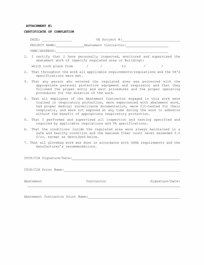
ATTACHMENT #1
CERTIFICATE OF COMPLETION
DATE: VA Project #:
PROJECT NAME: Abatement Contractor:
VAMC/ADDRESS:
1. I certify that I have personally inspected, monitored and supervised the abatement work of (specify regulated area or Building):
which took place from / / to / /
2. That throughout the work all applicable requirements/regulations and the VA's specifications were met.
3. That any person who entered the regulated area was protected with the appropriate personal protective equipment and respirator and that they followed the proper entry and exit procedures and the proper operating procedures for the duration of the work.
4. That all employees of the Abatement Contractor engaged in this work were trained in respiratory protection, were experienced with abatement work, had proper medical surveillance documentation, were fit-tested for their respirator, and were not exposed at any time during the work to asbestos without the benefit of appropriate respiratory protection.
5. That I performed and supervised all inspection and testing specified and required by applicable regulations and VA specifications.
6. That the conditions inside the regulated area were always maintained in a safe and healthy condition and the maximum fiber count never exceeded 0.5 f/cc, except as described below.
7. That all glovebag work was done in accordance with OSHA requirements and the manufacturer’s recommendations.
CPIH/CIH Signature/Date:
CPIH/CIH Print Name:
Abatement Contractor Signature/Date:
Abatement Contractor Print Name:

ATTACHMENT #2
CERTIFICATE OF WORKER'S ACKNOWLEDGMENT
PROJECT NAME: DATE:
PROJECT ADDRESS:
ABATEMENT CONTRACTOR'S NAME:
WORKING WITH ASBESTOS CAN BE HAZARDOUS TO YOUR HEALTH. INHALING ASBESTOS HAS BEEN LINKED WITH VARIOUS TYPES OF CANCERS. IF YOU SMOKE AND INHALE ASBESTOS FIBERS, YOUR CHANCES OF DEVELOPING LUNG CANCER IS GREATER THAN THAT OF THE NON-SMOKING PUBLIC.
Your employer's contract with the owner for the above project requires that: You must be supplied with the proper personal protective equipment including an adequate respirator and be trained in its use. You must be trained in safe and healthy work practices and in the use of the equipment found at an asbestos abatement project. You must receive/have a current medical examination for working with asbestos. These things shall be provided at no cost to you. By signing this certificate you are indicating to the owner that your employer has met these obligations.
RESPIRATORY PROTECTION: I have been trained in the proper use of respirators and have been informed of the type of respirator to be used on the above indicated project. I have a copy of the written Respiratory Protection Program issued by my employer. I have been provided for my exclusive use, at no cost, with a respirator to be used on the above indicated project.
TRAINING COURSE: I have been trained by a third party, State/EPA accredited trainer in the requirements for an AHERA/OSHA Asbestos Abatement Worker training course, 32 hours minimum duration. I currently have a valid State accreditation certificate. The topics covered in the course include, as a minimum, the following:
Physical Characteristics and Background Information on Asbestos Potential Health Effects Related to Exposure to Asbestos Employee Personal Protective Equipment Establishment of a Respiratory Protection Program State of the Art Work Practices Personal Hygiene Additional Safety Hazards Medical Monitoring Air Monitoring Relevant Federal, State and Local Regulatory Requirements, Procedures, and Standards Asbestos Waste Disposal
MEDICAL EXAMINATION: I have had a medical examination within the past 12 months which was paid for by my employer. This examination included: health history, occupational history, pulmonary function test, and may have included a chest x-ray evaluation. The physician issued a positive written opinion after the examination.
Signature:
Printed Name:
Social Security Number:
Witness:

ATTACHMENT #3
AFFIDAVIT OF MEDICAL SURVEILLANCE, RESPIRATORY PROTECTION AND TRAINING/ACCREDITATION
VA PROJECT NAME AND NUMBER:
VA MEDICAL FACILITY:
ABATEMENT CONTRACTOR'S NAME AND ADDRESS:
1. I verify that the following individual
Name: Social Security Number:
who is proposed to be employed in asbestos abatement work associated with the above project by the named Abatement Contractor, is included in a medical surveillance program in accordance with 29 CFR 1926.1101(m), and that complete records of the medical surveillance program as required by 29 CFR 1926.1101(m)(n) and 29 CFR 1910.20 are kept at the offices of the Abatement Contractor at the following address.
Address:
2. I verify that this individual has been trained, fit-tested and instructed in the use of all appropriate respiratory protection systems and that the person is capable of working in safe and healthy manner as expected and required in the expected work environment of this project.
3. I verify that this individual has been trained as required by 29 CFR 1926.1101(k). This individual has also obtained a valid State accreditation certificate. Documentation will be kept on-site.
4. I verify that I meet the minimum qualifications criteria of the VA specifications for a CPIH.
Signature of CPIH/CIH: Date:
Printed Name of CPIH/CIH:
Signature of Contractor: Date:
Printed Name of Contractor:

ATTACHMENT #4
ABATEMENT CONTRACTOR/COMPETENT PERSON(S) REVIEW AND ACCEPTANCE OF THE VA’S ASBESTOS SPECIFICATIONS
VA Project Location:
VA Project #:
VA Project Description:
This form shall be signed by the Asbestos Abatement Contractor Owner and the Asbestos Abatement Contractor’s Competent Person(s) prior to any start of work at the VA related to this Specification. If the Asbestos Abatement Contractor’s/Competent Person(s) has not signed this form, they shall not be allowed to work on-site.
I, the undersigned, have read VA’s Asbestos Specification regarding the asbestos abatement requirements. I understand the requirements of the VA’s Asbestos Specification and agree to follow these requirements as well as all required rules and regulations of OSHA/EPA/DOT and State/Local requirements. I have been given ample opportunity to read the VA’s Asbestos Specification and have been given an opportunity to ask any questions regarding the content and have received a response related to those questions. I do not have any further questions regarding the content, intent and requirements of the VA’s Asbestos Specification.
At the conclusion of the asbestos abatement, I will certify that all asbestos abatement work was done in accordance with the VA’s Asbestos Specification and all ACM was removed properly and no fibrous residue remains on any abated surfaces.
Abatement Contractor Owner’s Signature Date
Abatement Contractor Competent Person(s) Date
- - END- - - -

SECTION 02 82 13.19 ASBESTOS FLOOR TILE AND MASTIC ABATEMENT
TABLE OF CONTENTS
PART 1 - GENERAL............................................................ 1
1.1 SUMMARY OF THE WORK..................................................... 1
1.1.1 CONTRACT DOCUMENTS AND RELATED REQUIREMENTS........................... 1
1.1.2 EXTENT OF WORK........................................................ 2
1.1.3 RELATED WORK.......................................................... 2
1.1.4 TASKS................................................................. 2
1.1.5 ABATEMENT CONTRACTOR USE OF PREMISES.................................. 2
1.2 VARIATIONS IN QUANTITY.................................................. 2
1.3 STOP ASBESTOS REMOVAL................................................... 3
1.4 DEFINITIONS............................................................. 3
1.4.1 GENERAL............................................................... 3
1.4.2 GLOSSARY.............................................................. 3
1.4.3 REFERENCED STANDARDS ORGANIZATIONS.................................... 9
1.5 APPLICABLE CODES AND REGULATIONS....................................... 11
1.5.1 GENERAL APPLICABILITY OF CODES, REGULATIONS, AND STANDARDS........... 11
1.5.2 CONTRACTOR RESPONSIBILITY............................................ 11
1.5.3 FEDERAL REQUIREMENTS................................................. 11
1.5.4 STATE REQUIREMENTS......................... Error! Bookmark not defined.
1.5.5 LOCAL REQUIREMENTS......................... Error! Bookmark not defined.
1.5.6 STANDARDS............................................................ 12
1.5.7 EPA GUIDANCE DOCUMENTS............................................... 12
1.5.8 NOTICES.............................................................. 12
1.5.9 PERMITS/LICENSES..................................................... 12
1.5.10 POSTING AND FILING OF REGULATIONS................................... 13
1.5.11 VA RESPONSIBILITIES................................................. 13
1.5.12 SITE SECURITY....................................................... 13
1.5.13 EMERGENCY ACTION PLAN AND ARRANGEMENTS.............................. 14
1.5.14 PRE-construction MEETING............................................ 14
1.6 PROJECT COORDINATION................................................... 15
1.6.1 PERSONNEL............................................................ 15
1.7 RESPIRATORY PROTECTION................................................. 16
1.7.1 GENERAL - RESPIRATORY PROTECTION PROGRAM............................. 16
1.7.2 RESPIRATORY PROTECTION PROGRAM COORDINATOR........................... 16
1.7.3 SELECTION AND USE OF RESPIRATORS..................................... 16

1.7.4 MINIMUM RESPIRATORY PROTECTION....................................... 17
1.7.5 MEDICAL WRITTEN OPINION.............................................. 17
1.7.6 RESPIRATOR FIT TEST.................................................. 17
1.7.7 RESPIRATOR FIT CHECK................................................. 17
1.7.8 MAINTENANCE AND CARE OF RESPIRATORS.................................. 17
1.8 WORKER PROTECTION...................................................... 17
1.8.1 TRAINING OF ABATEMENT PERSONNEL...................................... 17
1.8.2 MEDICAL EXAMINATIONS................................................. 18
1.8.3 PERSONAL PROTECTIVE EQUIPMENT........................................ 18
1.8.4 REGULATED AREA ENTRY PROCEDURE....................................... 18
1.8.5 DECONTAMINATION PROCEDURE............................................ 18
1.8.6 REGULATED AREA REQUIREMENTS.......................................... 18
PART 2 - PRODUCTS, MATERIALS AND EQUIPMENT................................. 22
2.1 MATERIALS AND EQUIPMENT................................................ 22
2.1.1 GENERAL REQUIREMENTS (all abatement projects)........................ 22
2.1.2 NEGATIVE PRESSURE FILTRATION SYSTEM.................................. 23
2.1.3 DESIGN AND LAYOUT.................................................... 23
2.1.4 NEGATIVE AIR MACHINES (HEPA UNITS)................................... 24
2.1.5 PRESSURE DIFFERENTIAL................................................ 25
.2.2 CONTAINMENT BARRIERS AND COVERINGS IN THE REGULATED AREA.............. 25
2.2.1 GENERAL.............................................................. 25
2.2.3 CONTROLLING ACCESS TO THE REGULATED AREA............................. 25
2.2.4 CRITICAL BARRIERS.................................................... 25
2.2.5 secondary barriers:.................................................. 25
2.2.6 EXTENSION OF THE REGULATED AREA...................................... 26
2.3 MONITORING, INSPECTION AND TESTING..................................... 26
2.3.1 GENERAL.............................................................. 26
2.3.2 SCOPE OF SERVICES OF THE VPIH/CIH CONSULTANT......................... 27
2.3.3 MONITORING, INSPECTION AND TESTING BY CONTRACTOR CPIH/CIH............ 28
2.4 asbestos hazard abatement plan......................................... 28
2.5 SUBMITTALS............................................................. 29
2.5.1 PRE-start MEETING SUBMITTALS......................................... 29
2.5.2 SUBMITTALS DURING ABATEMENT.......................................... 31
2.5.3 SUBMITTALS AT COMPLETION OF ABATEMENT................................ 31
PART 3 - EXECUTION......................................................... 31
3.1 PRE-ABATEMENT ACTIVITIES............................................... 31
3.1.1 PRE-ABATEMENT MEETING................................................ 31

3.1.2 PRE-ABATEMENT INSPECTIONS AND PREPARATIONS........................... 32
3.1.3 PRE-ABATEMENT CONSTRUCTION AND OPERATIONS............................ 32
3.2 REGULATED AREA PREPARATIONS............................................ 33
3.2.1 OSHA DANGER SIGNS.................................................... 33
3.2.2 CONTROLLING ACCESS TO THE REGULATED AREA............................. 33
3.2.3 SHUT DOWN - LOCK OUT ELECTRICAL...................................... 33
3.2.4 SHUT DOWN - LOCK OUT HVAC............................................ 33
3.2.5 SANITARY FACILITIES.................................................. 33
3.2.7 PREPARATION PRIOR TO SEALING OFF..................................... 33
3.2.8 Critical Barriers.................................................... 34
3.2.10 PRE-CLEANING MOVABLE OBJECTS........................................ 34
3.2.11 PRE-CLEANING FIXED OBJECTS.......................................... 34
3.2.12 PRE-CLEANING SURFACES IN THE REGULATED AREA......................... 34
3.2.13 EXTENSION OF THE REGULATED AREA..................................... 35
3.3 REMOVAL OF CLASS II FLOORING; ROOFING; AND TRANSITE MATERIALS:......... 35
3.3.1 GENERAL.............................................................. 35
3.3.2 REMOVAL OF flooring materials:....................................... 35
3.3.3 REMOVAL OF MASTIC.................................................... 35
3.4 DISPOSAL OF CLASS ii WASTE MATERIAL:................................... 36
3.4.1 GENERAL.............................................................. 36
3.5 PROJECT DECONTAMINATION................................................ 36
3.5.1 GENERAL.............................................................. 36
3.5.2 REGULATED AREA CLEARANCE............................................. 36
3.5.3 WORK DESCRIPTION..................................................... 36
3.5.4 PRE-DECONTAMINATION CONDITIONS....................................... 36
3.5.5 CLEANING:............................................................ 37
3.6 VISUAL INSPECTION AND AIR CLEARANCE TESTING............................ 37
3.6.1 GENERAL.............................................................. 37
3.6.2 VISUAL INSPECTION.................................................... 37
3.6.3 AIR CLEARANCE TESTING................................................ 37
3.6.4 final AIR CLEARANCE PROCEDURES....................................... 37
3.7 ABATEMENT CLOSEOUT AND CERTIFICATE OF COMPLIANCE....................... 38
3.7.1 COMPLETION OF ABATEMENT WORK......................................... 38
3.7.2 CERTIFICATE OF COMPLETION BY CONTRACTOR.............................. 38
3.7.3 WORK SHIFTS.......................................................... 38
ATTACHMENT #1.............................................................. 39
ATTACHMENT #2.............................................................. 40

ATTACHMENT #3.............................................................. 41
ATTACHMENT #4.............................................................. 42

INSTRUCTIONS TO ARCHITECT/ENGINEER AND INDUSTRIAL HYGIENE CONSULTANT SECTION
02 82 13.19 ASBESTOS FLOOR TILE AND MASTIC ABATEMENT SPECIFICATIONS
1. These specifications provide general guidance to personnel given the
task of designing and executing a Class II asbestos flooring abatement project. Each abatement is a unique situation and therefore must be tailored for that project. This specification incorporates current regulatory requirements and current best abatement practices, procedures and technology. The Architect/Engineer and/or the Industrial Hygiene consultants may provide additional specification additions or deletions to this specification that, in their professional judgment, will ensure a safe and effective approach to a specific abatement project while maintaining compliance with applicable regulations and VA policy. Any changes must be clearly marked on/attached to this document prior to finalization of the specification so that the changes will be adequately considered in the review process by the VA.
2. These specifications are to be used in conjunction with asbestos abatement contractor selection criteria; special instructions package; and general construction provisions.
3. Paragraphs that are not preceded by a number code are indented as instructions to the specifications writer and identified by the notation "Spec Writer Notes". These paragraphs must be deleted from the final document.
4. Within the text of the specifications, there may be optional procedures which the specification writer could include in the final specification. Procedures which are not chosen must be deleted by the specification writer. Optional text is shown by the notation.
5. The specification writer, VPIH/CIH, CPIH/CIH, and A/E must be aware of and read the AEQA 10-95 since it details common errors in specification and contract documents for asbestos project. This would be especially helpful if a survey is being conducted prior to an abatement project. A full AHERA survey of the facility would be needed prior to renovation activities, however, if demolition of the facility is planned, a NESHAP-compliant survey of the facility would need to be performed.
PART 1 - GENERAL
1.1 SUMMARY OF THE WORK
1.1.1 CONTRACT DOCUMENTS AND RELATED REQUIREMENTS
Drawings, general provisions of the contract, including general and supplementary conditions and other Division 01 specifications, shall apply to the work of this section. The contract documents show the work to be done under the contract and related requirements and conditions impacting the project. Related requirements and conditions include applicable codes and regulations, notices and permits, existing site conditions and restrictions on use of the site, requirements for partial owner occupancy during the work, coordination with other work and the phasing of the work. In the event the Asbestos Abatement Contractor discovers a conflict in the contract documents and/or requirements or codes, the conflict must be brought to the immediate attention of the Contracting Officer for resolution. Whenever there is a conflict or overlap in the requirements, the most stringent shall apply. Any actions taken by the Contractor without obtaining guidance from the Contracting

Officer shall become the sole risk and responsibility of the Asbestos Abatement Contractor. All costs incurred due to such action are also the responsibility of the Asbestos Abatement Contractor.
1.1.2 EXTENT OF WORK
A. Below is a brief description of the estimated quantities of asbestos flooring materials to be abated. These quantities are for informational purposes only and are based on the best information available at the time of the specification preparation. The Contractor shall satisfy himself as the actual quantities to be abated. Nothing in this section may be interpreted as limiting the extent of work otherwise required by this contract and related documents.
B. Removal, clean-up and disposal of ACM flooring in an appropriate regulated area.
1.1.3 RELATED WORK
A. Section 07 84 00, FIRESTOPPING. B. Section 02 41 00, DEMOLITION. C. Division 09, FINISHES.
1.1.4 TASKS
The work tasks are summarized briefly as follows: A. Pre-abatement activities including pre-abatement meeting(s),
inspection(s), notifications, permits, submittal approvals, regulated area preparations, emergency procedures arrangements, and Asbestos Hazard Abatement Plans for asbestos abatement work.
B. Abatement activities including removal, encapsulation, enclosure, clean-up and disposal of ACM waste, recordkeeping, security, monitoring, and inspections.
C. Cleaning and decontamination activities including final visual inspection, air monitoring and certification of decontamination.
1.1.5 ABATEMENT CONTRACTOR USE OF PREMISES
A. The Contractor and Contractor's personnel shall cooperate fully with the VA representative/consultant to facilitate efficient use of buildings and areas within buildings. The Contractor shall perform the work in accordance with the VA specifications, drawings, phasing plan and in compliance with any/all applicable Federal, State and Local regulations and requirements.
B. The Contractor shall use the existing facilities in the building strictly within the limits indicated in contract documents as well as the approved VA Design Construction Procedure. VA Design Construction Procedure drawings of partially occupied buildings will show the limits of regulated areas; the placement of decontamination facilities; the temporary location of bagged waste ACM; the path of transport to outside the building; and the temporary waste storage area for each building/regulated area. Any variation from the arrangements shown on drawings shall be secured in writing from the VA representative through the pre-abatement plan of action. The following limitations of use shall apply to existing facilities shown on drawings:
1.2 VARIATIONS IN QUANTITY
The quantities and locations of ACM as indicated on the drawings and the extent of work included in this section are estimated which are limited

by the physical constraints imposed by occupancy of the buildings and accessibility to ACM. Accordingly, minor variations (+/- 5%) in quantities of ACM within the regulated area are considered as having no impact on contract price and time requirements of this contract. Where additional work is required beyond the above variation, the contractor shall provide unit prices for newly discovered ACM and those prices shall be used for additional work required under the contractor.
1.3 STOP ASBESTOS REMOVAL
If the Contracting Officer; their field representative; (the facility Safety Officer/Manager or their designee, or the VA Professional Industrial Hygienist/Certified Industrial Hygienist (VPIH/CIH) presents a verbal Stop Asbestos Removal Order, the Contractor/Personnel shall immediately stop all asbestos removal and maintain HEPA filtered negative pressure air flow in the containment and adequately wet any exposed ACM. If a verbal Stop Asbestos Removal Order is issued, the VA shall follow-up with a written order to the Contractor as soon as it is practicable. The Contractor shall not resume any asbestos removal activity until authorized to do so in writing by the VA Contracting Officer. A stop asbestos removal order may be issued at any time the VA Contracting Officer determines abatement conditions/activities are not within VA specification, regulatory requirements or that an imminent hazard exists to human health or the environment. Work stoppage will continue until conditions have been corrected to the satisfaction of the VA. Standby time and costs for corrective actions will be borne by the Contractor, including the VPIH/CIH time. The occurrence of any of the following events shall be reported immediately by the Contractor’s competent person to the VA Contracting Office or field representative using the most expeditious means (e.g., verbal or telephonic), followed up with written notification to the Contracting Officer as soon as practical. The Contractor shall immediately stop asbestos removal/disturbance activities and initiate fiber reduction activities:
A. Airborne PCM analysis results equal to or greater than 0.01 f/cc outside a regulated area or >0.05 f/cc inside a regulated area;
B. breach or break in regulated area containment barrier(s); C. less than –0.02” WCG pressure in the regulated area; D. serious injury/death at the site; E. fire/safety emergency at the site; F. respiratory protection system failure; G. power failure or loss of wetting agent; or H. any visible emissions observed outside the regulated area.
1.4 DEFINITIONS
1.4.1 GENERAL
Definitions and explanations here are neither complete nor exclusive of all terms used in the contract documents, but are general for the work to the extent they are not stated more explicitly in another element of the contract documents. Drawings must be recognized as diagrammatic in nature and not completely descriptive of the requirements indicated therein.
1.4.2 GLOSSARY
Abatement - Procedures to control fiber release from asbestos-containing materials. Includes removal, encapsulation, enclosure, demolition, and renovation activities related to asbestos containing materials (ACM).
Aerosol - Solid or liquid particulate suspended in air.
Adequately wet - Sufficiently mixed or penetrated with liquid to prevent the release of particulates. If visible emissions are observed coming from the ACM, then that material has not been adequately wetted.
Aggressive method - Removal or disturbance of building material by sanding, abrading, grinding, or other method that breaks, crumbles, or disintegrates intact ACM.
Aggressive sampling - EPA AHERA defined clearance sampling method using air moving equipment such as fans and leaf blowers to aggressively disturb and maintain in the air residual fibers after abatement.
AHERA - Asbestos Hazard Emergency Response Act. Asbestos regulations for schools issued in 1987.
Aircell - Pipe or duct insulation made of corrugated cardboard which contains asbestos.
Air monitoring - The process of measuring the fiber content of a known volume of air collected over a specified period of time. The NIOSH 7400 Method, Issue 2 is used to determine the fiber levels in air. For personal samples and clearance air testing using Phase Contrast Microscopy (PCM) analysis. NIOSH Method 7402 can be used when it is necessary to confirm fibers counted by PCM as being asbestos. The AHERA TEM analysis may be used for background, area samples and clearance samples when required by this specification, or at the discretion of the VPIH/CIH as appropriate.
Air sample filter - The filter used to collect fibers which are then counted. The filter is made of mixed cellulose ester membrane for PCM (Phase Contrast Microscopy) and polycarbonate for TEM (Transmission Electron Microscopy)
Amended water - Water to which a surfactant (wetting agent) has been added to increase the penetrating ability of the liquid.
Asbestos - Includes chrysotile, amosite, crocidolite, tremolite asbestos, anthophyllite asbestos, actinolite asbestos, and any of these minerals that have been chemically treated or altered. Asbestos also includes PACM, as defined below.
Asbestos Hazard Abatement Plan (AHAP) - Asbestos work procedures required to be submitted by the contractor before work begins.
Asbestos-containing material (ACM) - Any material containing more than one percent of asbestos.
Asbestos contaminated elements (ACE) - Building elements such as ceilings, walls, lights, or ductwork that are contaminated with asbestos.
Asbestos-contaminated soil (ACS) – Soil found in the work area or in adjacent areas such as crawlspaces or pipe tunnels which is contaminated with asbestos-containing material debris and cannot be easily separated from the material.
Asbestos-containing waste (ACW) material - Asbestos-containing material or asbestos contaminated objects requiring disposal.
Asbestos Project Monitor – Some sates require that any person conducting asbestos abatement clearance inspections and clearance air sampling be licensed as an asbestos project monitor.
Asbestos waste decontamination facility - A system consisting of drum/bag washing facilities and a temporary storage area for cleaned containers of asbestos waste. Used as the exit for waste and equipment leaving the regulated area. In an emergency, it may be used to evacuate personnel.
Authorized person - Any person authorized by the VA, the Contractor, or government agency and required by work duties to be present in regulated areas.
Authorized visitor - Any person approved by the VA; the contractor; or any government agency representative having jurisdiction over the regulated area (e.g., OSHA, Federal and State EPA0..
Barrier - Any surface the isolates the regulated area and inhibits fiber migration from the regulated area.
Containment Barrier - An airtight barrier consisting of walls, floors, and/or ceilings of sealed plastic sheeting which surrounds and seals the outer perimeter of the regulated area.
Critical Barrier - The barrier responsible for isolating the regulated area from adjacent spaces, typically constructed of plastic sheeting secured in place at openings such as doors, windows, or any other opening into the regulated area.
Primary Barrier – Plastic barriers placed over critical barriers and exposed directly to abatement work.
Secondary Barrier - Any additional plastic barriers used to isolate and provide protection from debris during abatement work.
Breathing zone - The hemisphere forward of the shoulders with a radius of about 150 - 225 mm (6 - 9 inches) from the worker's nose.
Bridging encapsulant - An encapsulant that forms a layer on the surface of the ACM.
Building/facility owner - The legal entity, including a lessee, which exercises control over management and recordkeeping functions relating to a building and/or facility in which asbestos activities take place.
Bulk testing - The collection and analysis of suspect asbestos containing materials.
Certified Industrial Hygienist (CIH) - A person certified in the comprehensive practice of industrial hygiene by the American Board of Industrial Hygiene.
Class I asbestos work - Activities involving the removal of Thermal System Insulation (TSI) and surfacing ACM and Presumed Asbestos Containing Material (PACM).
Class II asbestos work - Activities involving the removal of ACM which is not thermal system insulation or surfacing material. This includes, but is not limited to, the removal of asbestos-containing wallboard, floor tile and sheeting, roofing and siding shingles, and construction mastic.
Clean room/Changing room - An uncontaminated room having facilities for the storage of employee's street clothing and uncontaminated materials and equipment.
Clearance sample - The final air sample taken after all asbestos work has been done and visually inspected. Performed by the VA's professional industrial hygiene consultant/Certified Industrial Hygienist (VPIH/CIH).
Closely resemble - The major workplace conditions which have contributed to the levels of historic asbestos exposure, are no more protective than conditions of the current workplace.
Competent person - In addition to the definition in 29 CFR 1926.32(f), one who is capable of identifying existing asbestos hazards in the workplace and selecting the appropriate control strategy for asbestos exposure, who has the authority to take prompt corrective measures to eliminate them, as specified in 29 CFR 1926.32(f); in addition, for Class I and II work who is specially trained in a training course which meets the criteria of EPA's Model Accreditation Plan (40 CFR 763) for supervisor.
Contractor's Professional Industrial Hygienist (CPIH/CIH) - The asbestos abatement contractor's industrial hygienist. The industrial hygienist must meet the qualification requirements of a PIH and may be a certified industrial hygienist (CIH).
Count - Refers to the fiber count or the average number of fibers greater than five microns in length with a length-to-width (aspect) ratio of at least 3 to 1, per cubic centimeter of air.
Crawlspace – An area which can be found either in or adjacent to the work area. This area has limited access and egress and may contain asbestos materials and/or asbestos contaminated soil.
Decontamination area/unit - An enclosed area adjacent to and connected to the regulated area and consisting of an equipment room, shower room, and clean room, which is used for the decontamination of workers, materials, and equipment that are contaminated with asbestos.
Demolition - The wrecking or taking out of any load-supporting structural member and any related razing, removing, or stripping of asbestos products.
VA Total – means a building or substantial part of the building is completely removed, torn or knocked down, bulldozed, flattened, or razed, including removal of building debris.
Disposal bag - Typically 6 mil thick sift-proof, dustproof, leak-tight container used to package and transport asbestos waste from regulated areas to the approved landfill. Each bag/container must be labeled/marked in accordance with EPA, OSHA and DOT requirements.
Disturbance - Activities that disrupt the matrix of ACM or PACM, crumble or pulverize ACM or PACM, or generate visible debris from ACM or PACM. Disturbance includes cutting away small amounts of ACM or PACM, no greater than the amount that can be contained in one standard sized glove bag or waste bag in order to access a building component. In no event shall the amount of ACM or PACM so disturbed exceed that which can be contained in one glove bag or disposal bag which shall not exceed 60 inches in length or width.
Drum - A rigid, impermeable container made of cardboard fiber, plastic, or metal which can be sealed in order to be sift-proof, dustproof, and leak-tight.
Employee exposure - The exposure to airborne asbestos that would occur if the employee were not wearing respiratory protection equipment.
Encapsulant - A material that surrounds or embeds asbestos fibers in an adhesive matrix and prevents the release of fibers.
Encapsulation - Treating ACM with an encapsulant. Enclosure - The construction of an air tight, impermeable, permanent
barrier around ACM to control the release of asbestos fibers from the material and also eliminate access to the material.
Equipment room - A contaminated room located within the decontamination area that is supplied with impermeable bags or containers for the disposal of contaminated protective clothing and equipment.
Fiber - A particulate form of asbestos, 5 microns or longer, with a length to width (aspect) ratio of at least 3 to 1.
Fibers per cubic centimeter (f/cc) - Abbreviation for fibers per cubic centimeter, used to describe the level of asbestos fibers in air.
Filter - Media used in respirators, vacuums, or other machines to remove particulate from air.
Firestopping - Material used to close the open parts of a structure in order to prevent a fire from spreading.
Friable asbestos containing material - Any material containing more than one (1) percent or asbestos as determined using the method specified in appendix A, Subpart F, 40 CFR 763, section 1, Polarized Light Microscopy, that, when dry, can be crumbled, pulverized, or reduced to powder by hand pressure.
Glovebag - Not more than a 60 x 60 inch impervious plastic bag-like enclosure affixed around an asbestos-containing material, with glove-like appendages through which materials and tools may be handled.

High efficiency particulate air (HEPA) filter – An ASHRAE MERV 17 filter capable of trapping and retaining at least 99.97 percent of all mono-dispersed particles of 0.3 micrometers in diameter.
HEPA vacuum - Vacuum collection equipment equipped with a HEPA filter system capable of collecting and retaining asbestos fibers.
Homogeneous area - An area of surfacing, thermal system insulation or miscellaneous ACM that is uniform in color, texture and date of application.
HVAC - Heating, Ventilation and Air Conditioning Industrial hygienist (IH) - A professional qualified by education, training,
and experience to anticipate, recognize, evaluate and develop controls for occupational health hazards. Meets definition requirements of the American Industrial Hygiene Association (AIHA).
Industrial hygienist technician (IH Technician) - A person working under the direction of an IH or CIH who has special training, experience, certifications and licenses required for the industrial hygiene work assigned. Some states require that an industrial hygienist technician conducting asbestos abatement clearance inspection and clearance air sampling be licensed as an asbestos project monitor.
Intact - The ACM has not crumbled, been pulverized, or otherwise deteriorated so that the asbestos is no longer likely to be bound with its matrix.
Lockdown - Applying encapsulant, after a final visual inspection, on all abated surfaces at the conclusion of ACM removal prior to removal of critical barriers.
National Emission Standards for Hazardous Air Pollutants (NESHAP) - EPA's rule to control emissions of asbestos to the environment (40 CFR Part 61, Subpart M).
Negative initial exposure assessment - A demonstration by the employer which complies with the criteria in 29 CFR 1926.1101 (f)(2)(iii), that employee exposure during an operation is expected to be consistently below the PELs.
Negative pressure - Air pressure which is lower than the surrounding area, created by exhausting air from a sealed regulated area through HEPA equipped filtration units. OSHA requires maintaining -0.02" water column gauge inside the negative pressure enclosure.
Negative pressure respirator - A respirator in which the air pressure inside the facepiece is negative during inhalation relative to the air pressure outside the respirator facepiece.
Non-friable ACM - Material that contains more than 1 percent asbestos but cannot be crumbled, pulverized, or reduced to powder by hand pressure.
Organic vapor cartridge - The type of cartridge used on air purifying respirators to remove organic vapor hazardous air contaminants.
Outside air - The air outside buildings and structures, including, but not limited to, the air under a bridge or in an open ferry dock.
Owner/operator - Any person who owns, leases, operates, controls, or supervises the facility being demolished or renovated or any person who owns, leases, operates, controls, or supervises the demolition or renovation operation, or both.
Penetrating encapsulant - Encapsulant that is absorbed into the ACM matrix without leaving a surface layer.
Personal protective equipment (PPE) – equipment designed to protect user from injury and/or specific job hazard. Such equipment may include protective clothing, hard hats, safety glasses, and respirators.
Personal sampling/monitoring - Representative air samples obtained in the breathing zone for one or workers within the regulated area using a filter

cassette and a calibrated air sampling pump to determine asbestos exposure.
Permissible exposure limit (PEL) - The level of exposure OSHA allows for an 8 hour time weighted average. For asbestos fibers, the eight (8) hour time weighted average PEL is 0.1 fibers per cubic centimeter (0.1 f/cc) of air and the 30-minute Excursion Limit is 1.0 fibers per cubic centimeter (1 f/cc).
Pipe Tunnel – An area, typically located adjacent to mechanical spaces or boiler rooms in which the pipes servicing the heating system in the building are routed to allow the pipes to access heating elements. These areas may contain asbestos pipe insulation, asbestos fittings, or asbestos-contaminated soil.
Polarized light microscopy (PLM) - Light microscopy using dispersion staining techniques and refractive indices to identify and quantify the type(s) of asbestos present in a bulk sample.
Polyethylene sheeting - Strong plastic barrier material 4 to 6 mils thick, semi-transparent, flame retardant per NFPA 241.
Positive/negative fit check - A method of verifying the seal of a facepiece respirator by temporarily occluding the filters and breathing in (inhaling) and then temporarily occluding the exhalation valve and breathing out (exhaling) while checking for inward or outward leakage of the respirator respectively.
Presumed ACM (PACM) - Thermal system insulation, surfacing, and flooring material installed in buildings prior to 1981. If the building owner has actual knowledge, or should have known through the exercise of due diligence that other materials are ACM, they too must be treated as PACM. The designation of PACM may be rebutted pursuant to 29 CFR 1926.1101 (b).
Professional IH - An IH who meets the definition requirements of AIHA; meets the definition requirements of OSHA as a "Competent Person" at 29 CFR 1926.1101 (b); has completed two specialized EPA approved courses on management and supervision of asbestos abatement projects; has formal training in respiratory protection and waste disposal; and has a minimum of four projects of similar complexity with this project of which at least three projects serving as the supervisory IH. The PIH may be either the VA’s PIH (VPIH) of Contractor’s PIH (CPIH/CIH).
Project designer - A person who has successfully completed the training requirements for an asbestos abatement project designer as required by 40 CFR 763 Appendix C, Part I; (B)(5).
Assigned Protection factor - A value assigned by OSHA/NIOSH to indicate the expected protection provided by each respirator class, when the respirator is properly selected and worn correctly. The number indicates the reduction of exposure level from outside to inside the respirator facepiece.
Qualitative fit test (QLFT) - A fit test using a challenge material that can be sensed by the wearer if leakage in the respirator occurs.
Quantitative fit test (QNFT) - A fit test using a challenge material which is quantified outside and inside the respirator thus allowing the determination of the actual fit factor.
Regulated area - An area established by the employer to demarcate where Class I, II, and III asbestos work is conducted, and any adjoining area where debris and waste from such asbestos work may accumulate; and a work area within which airborne concentrations of asbestos exceed, or there is a reasonable possibility they may exceed the PEL.
Regulated ACM (RACM) - Friable ACM; Category I non-friable ACM that has become friable; Category I non-friable ACM that will be or has been subjected to sanding, grinding, cutting, or abrading or; Category II non-friable ACM that has a high probability of becoming or has become

crumbled, pulverized, or reduced to powder by the forces expected to act on the material in the course of the demolition or renovation operation.
Removal - All operations where ACM, PACM and/or RACM is taken out or stripped from structures or substrates, including demolition operations.
Renovation - Altering a facility or one or more facility components in any way, including the stripping or removal of asbestos from a facility component which does not involve demolition activity.
Repair - Overhauling, rebuilding, reconstructing, or reconditioning of structures or substrates, including encapsulation or other repair of ACM or PACM attached to structures or substrates.
Shower room - The portion of the PDF where personnel shower before leaving the regulated area.
Supplied air respirator (SAR) - A respiratory protection system that supplies minimum Grade D respirable air per ANSI/Compressed Gas Association Commodity Specification for Air, G-7.1-1989.
Surfacing ACM - A material containing more than 1 percent asbestos that is sprayed, troweled on or otherwise applied to surfaces for acoustical, fireproofing and other purposes.
Surfactant - A chemical added to water to decrease water's surface tension thus making it more penetrating into ACM.
Thermal system ACM - A material containing more than 1 percent asbestos applied to pipes, fittings, boilers, breeching, tanks, ducts, or other structural components to prevent heat loss or gain.
Transmission electron microscopy (TEM) - A microscopy method that can identify and count asbestos fibers.
VA Professional Industrial Hygienist (VPIH/CIH) – The Department of Veterans Affairs Professional Industrial Hygienist must meet the qualifications of a PIH, and may be a Certified Industrial Hygienist (CIH).
VA Representative - The VA official responsible for on-going project work. Visible emissions - Any emissions, which are visually detectable without
the aid of instruments, coming from ACM/PACM/RACM/ACS or ACM waste material.
Waste/Equipment decontamination facility (W/EDF) – The area in which equipment is decontaminated before removal from the regulated area.
Waste generator - Any owner or operator whose act or process produces asbestos-containing waste material.
Waste shipment record - The shipping document, required to be originated and signed by the waste generator, used to track and substantiate the disposition of asbestos-containing waste material.
Wet cleaning - The process of thoroughly eliminating, by wet methods, any asbestos contamination from surfaces or objects.
1.4.3 REFERENCED STANDARDS ORGANIZATIONS
The following acronyms or abbreviations as referenced in contract/ specification documents are defined to mean the associated names. Names and addresses may be subject to change.
A. VA Department of Veterans Affairs 810 Vermont Avenue, NW Washington, DC 20420
B. AIHA American Industrial Hygiene Association
2700 Prosperity Avenue, Suite 250 Fairfax, VA 22031 703-849-8888

C. ANSI American National Standards Institute 1430 Broadway New York, NY 10018 212-354-3300
D. ASTM American Society for Testing and Materials
1916 Race St. Philadelphia, PA 19103 215-299-5400
E. CFR Code of Federal Regulations Government Printing Office Washington, DC 20420
F. CGA Compressed Gas Association 1235 Jefferson Davis Highway
Arlington, VA 22202 703-979-0900
G. CS Commercial Standard of the National Institute of Standards and
Technology (NIST) U. S. Department of Commerce Government Printing Office Washington, DC 20420
H. EPA Environmental Protection Agency
401 M St., SW Washington, DC 20460 202-382-3949
I. MIL-STD Military Standards/Standardization Division
Office of the Assistant Secretary of Defense Washington, DC 20420
I. NEC National Electrical Code (by NFPA) J. NEMA National Electrical Manufacturer's Association
2101 L Street, NW Washington, DC 20037
K. NFPA National Fire Protection Association
1 Batterymarch Park P.O. Box 9101 Quincy, MA 02269-9101 800-344-3555
L. NIOSH National Institutes for Occupational Safety and Health
4676 Columbia Parkway
Cincinnati, OH 45226 513-533-8236
M. OSHA Occupational Safety and Health Administration
U.S. Department of Labor Government Printing Office Washington, DC 20402
N. UL Underwriters Laboratory
333 Pfingsten Rd. Northbrook, IL 60062 312-272-8800
1.5 APPLICABLE CODES AND REGULATIONS
1.5.1 GENERAL APPLICABILITY OF CODES, REGULATIONS, AND STANDARDS
A. All work under this contract shall be done in strict accordance with all applicable Federal, State, and local regulations, standards and codes governing asbestos abatement, and any other trade work done in conjunction with the abatement. All applicable codes, regulations and standards are adopted into this specification and will have the same force and effect as this specification.
B. The most recent edition of any relevant regulation, standard, document or code shall be in effect. Where conflict among the requirements or with these specifications exists, the most stringent requirement(s) shall be utilized.
C. Copies of all standards, regulations, codes and other applicable documents, including this specification and those listed in Section 1.5 shall be available at the worksite in the clean change area of the worker decontamination system.
1.5.2 CONTRACTOR RESPONSIBILITY
The Asbestos Abatement Contractor (Contractor) shall assume full responsibility and liability for compliance with all applicable Federal, State and Local regulations related to any and all aspects of the asbestos abatement project. The Contractor is responsible for providing and maintaining training, accreditations, medical exams, medical records, personal protective equipment (PPE) including respiratory protection including respirator fit testing, as required by applicable Federal, State and Local regulations. The Contractor shall hold the VA and VPIH/CIH consultants harmless for any Contractor’s failure to comply with any applicable work, packaging, transporting, disposal, safety, health, or environmental requirement on the part of himself, his employees, or his subcontractors. The Contractor will incur all costs of the CPIH/CIH, including all sampling/analytical costs to assure compliance with OSHA/EPA/State requirements related to failure to comply with the regulations applicable to the work.
1.5.3 FEDERAL REQUIREMENTS
Federal requirements which govern some aspect of asbestos abatement include, but are not limited to, the following regulations.
A. Occupational Safety and Health Administration (OSHA) 1. Title 29 CFR 1926.1101 - Construction Standard for Asbestos 2. Title 29 CFR 1910.132 - Personal Protective Equipment 3. Title 29 CFR 1910.134 - Respiratory Protection 4. Title 29 CFR 1926 - Construction Industry Standards

5. Title 29 CFR 1910.20 - Access to Employee Exposure and Medical Records 6. Title 29 CFR 1910.1200 - Hazard Communication 7. Title 29 CFR 1910.151 - Medical and First Aid
B. Environmental Protection Agency (EPA) 1. 40 CFR 61 Subpart A and M (Revised Subpart B) - National Emission
Standard for Hazardous Air Pollutants - Asbestos. 2. 40 CFR 763.80 - Asbestos Hazard Emergency Response Act (AHERA)
C. Department of Transportation (DOT) Title 49 CFR 100 - 185 – Transportation
1.5.6 STANDARDS
A. Standards which govern asbestos abatement activities include, but are not limited to, the following: 1. American National Standards Institute (ANSI) Z9.2-79 - Fundamentals
Governing the Design and Operation of Local Exhaust Systems Z88.2 - Practices for Respiratory Protection.
2. Underwriters Laboratories (UL) 586-90 - UL Standard for Safety of HEPA filter Units, 7th Edition.
B. Standards which govern encapsulation work include, but are not limited to, the following: 1. American Society for Testing and Materials (ASTM)
C. Standards which govern the fire and safety concerns in abatement work include, but are not limited to, the following: 1. National Fire Protection Association (NFPA) 241 - Standard for
Safeguarding Construction, Alteration, and Demolition Operations. 2. NFPA 701 - Standard Methods for Fire Tests for Flame Resistant Textiles
and Film. 3. NFPA 101 - Life Safety Code
1.5.7 EPA GUIDANCE DOCUMENTS
A. EPA guidance documents which discuss asbestos abatement work activities are listed below. These documents are made part of this section by reference. EPA publications can be ordered from (800) 424-9065.
B. Guidance for Controlling ACM in Buildings (Purple Book) EPA 560/5-85-024 C. Asbestos Waste Management Guidance EPA 530-SW-85-007 D. A Guide to Respiratory Protection for the Asbestos Abatement Industry EPA-
560-OPTS-86-001 E. Guide to Managing Asbestos in Place (Green Book) TS 799 20T July 1990
1.5.8 NOTICES
A. State and Local agencies: Send written notification as required by state and local regulations including the local fire department prior to beginning any work on ACM as follows:
B. Copies of notifications shall be submitted to the VA for the facility's records in the same time frame notification are given to EPA, State, and Local authorities.
1.5.9 PERMITS/LICENSES
A. The contractor shall apply for and have all required permits and licenses to perform asbestos abatement work as required by Federal, State, and Local regulations.

1.5.10 POSTING AND FILING OF REGULATIONS
A. Maintain two (2) copies of applicable federal, state, and local regulations. Post one copy of each at the regulated area where workers will have daily access to the regulations and keep another copy in the Contractor's office.
1.5.11 VA RESPONSIBILITIES
Prior to commencement of work: A. Notify occupants adjacent to regulated areas of project dates and
requirements for relocation, if needed. Arrangements must be made prior to starting work for relocation of desks, files, equipments and personal possessions to avoid unauthorized access into the regulated area. Note: Notification of adjacent personnel is required by OSHA in 29 CFR 1926.1101 (k) to prevent unnecessary or unauthorized access to the regulated area.
B. Submit to the Contractor results of background air sampling; including location of samples, person who collected the samples, equipment utilized, calibration data and method of analysis. During abatement, submit to the Contractor, results of bulk material analysis and air sampling data collected during the course of the abatement. This information shall not release the Contractor from any responsibility for OSHA compliance.
1.5.12 SITE SECURITY
A. Regulated area access is to be restricted only to authorized, trained/accredited and protected personnel. These may include the Contractor's employees, employees of Subcontractors, VA employees and representatives, State and local inspectors, and any other designated individuals. A list of authorized personnel shall be established prior to commencing the project and be posted in the clean room of the decontamination unit.
B. Entry into the regulated area by unauthorized individuals shall be reported immediately to the Competent Person by anyone observing the entry. The Competent person shall immediately notify the VA.
C. A log book shall be maintained in the clean room of the decontamination unit. Anyone who enters the regulated area must record their name, affiliation, time in, and time out for each entry.
D. Access to the regulated area shall be through of a critical barrier doorway. All other access (doors, windows, hallways, etc.) shall be sealed or locked to prevent entry to or exit from the regulated area. The only exceptions for this requirement are the waste/equipment load-out area which shall be sealed except during the removal of containerized asbestos waste from the regulated area, and emergency exits. Emergency exits shall not be locked from the inside; however, they shall be sealed with poly sheeting and taped until needed.
E. The Contractor's Competent Person shall control site security during abatement operations in order to isolate work in progress and protect adjacent personnel. A 24 hour security system shall be provided at the entrance to the regulated area to assure that all entrants are logged in/out and that only authorized personnel are allowed entrance.
F. The Contractor will have the VA's assistance in notifying adjacent personnel of the presence, location and quantity of ACM in the regulated area and enforcement of restricted access by the VA's employees.
G. The regulated area shall be locked during non-working hours and secured by VA security guards.

1.5.13 EMERGENCY ACTION PLAN AND ARRANGEMENTS
A. An Emergency Action Plan shall be developed prior to commencing abatement activities and shall be agreed to by the Contractor and the VA. The Plan shall meet the requirements of 29 CFR 1910.38 (a);(b).
B. Emergency procedures shall be in written form and prominently posted in the clean room and equipment room of the decontamination unit. Everyone, prior to entering the regulated area, must read and sign these procedures to acknowledge understanding of the regulated area layout, location of emergency exits and emergency procedures.
C. Emergency planning shall include written notification of police, fire, and emergency medical personnel of planned abatement activities; work schedule; layout of regulated area; and access to the regulated area, particularly barriers that may affect response capabilities.
D. Emergency planning shall include consideration of fire, explosion, hazardous atmospheres, electrical hazards, slips/trips and falls, confined spaces, and heat stress illness. Written procedures for response to emergency situations shall be developed and employee training in procedures shall be provided.
E. Employees shall be trained in regulated area/site evacuation procedures in the event of workplace emergencies. 1. For non life-threatening situations - employees injured or otherwise
incapacitated shall decontaminate following normal procedures with assistance from fellow workers, if necessary, before exiting the regulated area to obtain proper medical treatment.
2. For life-threatening injury or illness, worker decontamination shall take least priority after measures to stabilize the injured worker, remove them from the regulated area, and secure proper medical treatment.
F. Telephone numbers of any/all emergency response personnel shall be prominently posted in the clean room, along with the location of the nearest telephone.
G. The Contractor shall provide verification of first aid/CPR training for personnel responsible for providing first aid/CPR. OSHA requires medical assistance within 3-4 minutes of a life-threatening injury/illness. Bloodborne Pathogen training shall also be verified for those personnel required to provide first aid/CPR.
H. The Emergency Action Plan shall provide for a Contingency Plan in the event that an incident occurs that may require the modification of the Asbestos Hazard Abatement Plans during abatement. Such incidents include, but are not limited to, fire; accident; power failure; negative pressure failure; and supplied air system failure. The Contractor shall detail procedures to be followed in the event of an incident assuring that asbestos abatement work is stopped and wetting is continued until correction of the problem.
1.5.14 PRE-CONSTRUCTION MEETING
Prior to commencing the work, the Contractor shall meet with the VA Certified Industrial Hygienist (VPCIH) to present and review, as appropriate, the items following this paragraph. The Contractor's Competent Person(s) who will be on-site shall participate in the pre-start meeting. The pre-start meeting is to discuss and determine procedures to be used during the project. At this meeting, the Contractor shall provide:
A. Proof of Contractor licensing.

B. Proof the Competent Person(s) is trained and accredited and approved for working in this State. Verification of the experience of the Competent Person(s) shall also be presented.
C. A list of all workers who will participate in the project, including experience and verification of training and accreditation.
D. A list of and verification of training for all personnel who have current first-aid/CPR training. A minimum of one person per shift must have adequate training.
E. Current medical written opinions for all personnel working on-site meeting the requirements of 29 CFR 1926.1101 (m).
F. Current fit-tests for all personnel wearing respirators on-site meeting the requirements of 29 CFR 1926.1101 (h) and Appendix C.
G. A copy of the Asbestos Hazard Abatement Plan. In these procedures, the following information must be detailed, specific for this project. 1. Regulated area preparation procedures; 2. Notification requirements procedure of Contractor as required in 29
CFR 1926.1101 (d); 3. Decontamination area set-up/layout and decontamination procedures for
employees; 4. Abatement methods/procedures and equipment to be used; 5. Personal protective equipment to be used;
H. At this meeting the Contractor shall provide all submittals as required. I. Procedures for handling, packaging and disposal of asbestos waste. J. Emergency Action Plan and Contingency Plan Procedures.
1.6 PROJECT COORDINATION
The following are the minimum administrative and supervisory personnel necessary for coordination of the work.
1.6.1 PERSONNEL
A. Administrative and supervisory personnel shall consist of a qualified Competent Person(s) as defined by OSHA in the Construction Standards and the Asbestos Construction Standard; Contractor Professional Industrial Hygienist and Industrial Hygiene Technicians. These employees are the Contractor's representatives responsible for compliance with these specifications and all other applicable requirements.
B. Non-supervisory personnel shall consist of an adequate number of qualified personnel to meet the schedule requirements of the project. Personnel shall meet required qualifications. Personnel utilized on-site shall be pre-approved by the VA representative. A request for approval shall be submitted for any person to be employed during the project giving the person's name; social security number; qualifications; accreditation card with color picture; Certificate of Worker's Acknowledgment; and Affidavit of Medical Surveillance and Respiratory Protection and current Respirator Fit Test.
C. Minimum qualifications for Contractor and assigned personnel are: 1. The Contractor has conducted within the last three (3) years, three
(3) projects of similar complexity and dollar value as this project; has not been cited and penalized for serious violations of federal (and state as applicable) EPA and OSHA asbestos regulations in the past three (3) years; has adequate liability/occurrence insurance for asbestos work as required by the state; is licensed in applicable states; has adequate and qualified personnel available to complete the work; has comprehensive Asbestos Hazard Abatement Plans for asbestos work; and has adequate materials, equipment and supplies to perform the work.

2. The Competent Person has four (4) years of abatement experience of which two (2) years were as the Competent Person on the project; meets the OSHA definition of a Competent Person; has been the Competent Person on two (2) projects of similar size and complexity as this project within the past three (3) years; has completed EPA AHERA/OSHA/State/Local training requirements/accreditation(s) and refreshers; and has all required OSHA documentation related to medical and respiratory protection.
3. The Contractor Professional Industrial Hygienist/CIH (CPIH/CIH) shall have five (5) years of monitoring experience and supervision of asbestos abatement projects; has participated as senior IH on five (5) abatement projects, three (3) of which are similar in size and complexity as this project; has developed at least one complete Asbestos Hazard Abatement Plan for asbestos abatement; has trained abatement personnel for three (3) years; has specialized EPA AHERA/OSHA training in asbestos abatement management, respiratory protection, waste disposal and asbestos inspection; has completed the NIOSH 582 Course or equivalent, Contractor/Supervisor course; and has appropriate medical/respiratory protection records/documentation.
4. The Abatement Personnel shall have completed the EPA AHERA/OSHA abatement worker course; have training on the Asbestos Hazard Abatement Plans of the Contractor; has one year of asbestos abatement experience within the past three (3) years of similar size and complexity; has applicable medical and respiratory protection documentation; and has certificate of training/current refresher and State accreditation/license.
All personnel should be in compliance with OSHA construction safety training as applicable and submit certification.
1.7 RESPIRATORY PROTECTION
1.7.1 GENERAL - RESPIRATORY PROTECTION PROGRAM
The Contractor shall develop and implement a written Respiratory Protection Program (RPP) which is in compliance with the January 8, 1998 OSHA requirements found at 29 CFR 1926.1101 and 29 CFR 1910.Subpart I;134. ANSI Standard Z88.2-1992 provides excellent guidance for developing a respiratory protection program. All respirators used must be NIOSH approved for asbestos abatement activities. The written RPP shall, at a minimum, contain the basic requirements found at 29 CFR 1910.134 (c)(1)(i - ix) - Respiratory Protection Program.
1.7.2 RESPIRATORY PROTECTION PROGRAM COORDINATOR
The Respiratory Protection Program Coordinator (RPPC) must be identified and shall have two (2) years experience coordinating RPP of similar size and complexity. The RPPC must submit a signed statement attesting to the fact that the program meets the above requirements.
1.7.3 SELECTION AND USE OF RESPIRATORS
The procedure for the selection and use of respirators must be submitted to the VA as part of the Contractor's qualifications. The procedure must written clearly enough for workers to understand. A copy of the Respiratory Protection Program must be available in the clean room of the decontamination unit for reference by employees or authorized visitors.

1.7.4 MINIMUM RESPIRATORY PROTECTION
Minimum respiratory protection shall be a half face, HEPA filtered, air purifying respirator when fiber levels are maintained consistently at or below 0.1 f/cc. A higher level of respiratory protection may be provided or required, depending on fiber levels. Respirator selection shall meet the requirements of 29 CFR 1926.1101 (h); Table 1, except as indicated in this paragraph. Abatement personnel must have a respirator for their exclusive use.
1.7.5 MEDICAL WRITTEN OPINION
No employee shall be allowed to wear a respirator unless a physician or other licensed health care professional has provided a written determination they are medically qualified to wear the class of respirator to be used on the project while wearing whole body impermeable garments and subjected to heat or cold stress.
1.7.6 RESPIRATOR FIT TEST
All personnel wearing respirators shall have a current qualitative/quantitative fit test which was conducted in accordance with 29 CFR 1910.134 (f) and Appendix A. Quantitative fit tests shall be done for PAPRs which have been put into a motor/blower failure mode.
1.7.7 RESPIRATOR FIT CHECK
The Competent Person shall assure that the positive/negative pressure user seal check is done each time the respirator is donned by an employee. Head coverings must cover respirator head straps. Any situation that prevents an effective facepiece to face seal as evidenced by failure of a user seal check shall preclude that person from wearing a respirator inside the regulated area until resolution of the problem.
1.7.8 MAINTENANCE AND CARE OF RESPIRATORS
The Respiratory Protection Program Coordinator shall submit evidence and documentation showing compliance with 29 CFR 1910.134 (h) Maintenance and Care of Respirators.
1.7.9 SUPPLIED AIR SYSTEMS
If a supplied air system is used, the system shall meet all requirements of 29 CFR 1910.134 and the ANSI/Compressed Gas Association (CGA) Commodity Specification for Air current requirements for Type 1 - Grade D breathing air. Low pressure systems are not allowed to be used on asbestos abatement projects. Supplied Air respirator use shall be in accordance with EPA/NIOSH publication EPA-560-OPTS-86-001 "A Guide to Respiratory Protection for the Asbestos Abatement Industry". The competent person on site will be responsible for the supplied air system to ensure the safety of the worker.
1.8 WORKER PROTECTION
1.8.1 TRAINING OF ABATEMENT PERSONNEL
Prior to beginning any abatement activity, all personnel shall be trained in accordance with OSHA 29 CFR 1926.1101 (k)(9) and any additional State/Local requirements. Training must include, at a minimum, the elements listed at 29 CFR 1926.1101 (k)(9)(viii). Training shall have

been conducted by a third party, EPA/State approved trainer meeting the requirements of EPA 40 CFR 763 Appendix C (AHERA MAP). Initial training certificates and current refresher and accreditation proof must be submitted for each person working at the site.
1.8.2 MEDICAL EXAMINATIONS
Medical examinations meeting the requirements of 29 CFR 1926.1101 (m) shall be provided for all personnel working in the regulated area, regardless of exposure levels. A current physician's written opinion as required by 29 CFR 1926.1101 (m)(4) shall be provided for each person and shall include in the medical opinion the person has been evaluated for working in a heat and cold stress environment while wearing personal protective equipment (PPE) and is able to perform the work without risk of material health impairment.
1.8.3 PERSONAL PROTECTIVE EQUIPMENT
Provide whole body clothing, head coverings, foot coverings and any other personal protective equipment as determined by conducting the hazard assessment required by OSHA at 29 CFR 1910.132 (d). The Competent Person shall ensure the integrity of personal protective equipment worn for the duration of the project. Duct tape shall be used to secure all suit sleeves to wrists and to secure foot coverings at the ankle. Worker protection shall meet the most stringent requirements.
1.8.4 REGULATED AREA ENTRY PROCEDURE
The Competent Person shall ensure that each time workers enter the regulated area they remove ALL street clothes in the clean room of the decontamination unit and put on new disposable coveralls, head coverings, a clean respirator, and then proceed through the shower room to the equipment room where they put on non-disposable required personal protective equipment.
1.8.5 DECONTAMINATION PROCEDURE
The Competent Person shall require all personnel to adhere to following decontamination procedures whenever they leave the regulated area.
A. When exiting the regulated area, remove all disposable PPE and dispose of in a disposal bag provided in the regulated area.
B. Carefully decontaminate and clean the respirator. Put in a clean container/bag.
1.8.6 REGULATED AREA REQUIREMENTS
The Competent Person shall meet all requirements of 29 CFR 1926.1101 (o) and assure that all requirements for Class I regulated areas at 29 CFR 1926.1101 (e) are met applicable to Class II work. All personnel in the regulated area shall not be allowed to eat, drink, smoke, chew tobacco or gum, apply cosmetics, or in any way interfere with the fit of their respirator.
1.9 DECONTAMINATION FACILITIES: 1.9.1 DESCRIPTION:
Provide each regulated area with separate personnel decontamination facilities (PDF) and waste/equipment decontamination facilities (W/EDF). Ensure that the PDF are the only means of ingress and egress to the

regulated area and that all equipment, bagged waste, and other material exit the regulated area only through the W/EDF.
1.9.2 GENERAL REQUIREMENTS
All personnel entering or exiting a regulated area must go through the PDF and shall follow the requirements at 29 CFR 1926.1101 (j)(1) and these specifications. All waste, equipment and contaminated materials must exit the regulated area through the W/EDF and be decontaminated in accordance with these specifications. Walls and ceilings of the PDF and W/EDF must be constructed of a minimum of 3 layers of 6 mil opaque fire retardant polyethylene sheeting and be securely attached to existing building components and/or an adequate temporary framework. A minimum of 3 layers of 6 mil poly shall also be used to cover the floor under the PDF and W/EDF units. Construct doors so that they overlap and secure to adjacent surfaces. Weight inner doorway sheets with layers of duct tape so that they close quickly after release. Put arrows on sheets so they show direction of travel and overlap. If the building adjacent area is occupied, construct a solid barrier on the occupied side(s) to protect the sheeting and reduce potential for non-authorized personnel entering the regulated area.
1.9.3 TEMPORARY FACILITIES TO THE PDF AND W/EDF The Competent Person shall provide temporary water service connections to
the PDF and W/EDF. Backflow prevention must be provided at the point of connection to the VA system. Water supply must be of adequate pressure and meet requirements of 29 CFR 1910.141 (d)(3). Provide adequate temporary overhead electric power with ground fault circuit interruption (GFCI) protection. Provide a sub-panel equipped with GFCI protection for all temporary power in the clean room. Provide adequate lighting to provide a minimum of 50 foot candles in the PDF and W/EDF. Provide temporary heat, if needed, to maintain 70oF throughout the PDF and W/EDF.
1.9.4 PERSONNEL DECONTAMINATION FACILITY (PDF)
1. Clean Room: The clean room must be physically and visually separated from the rest of the building to protect the privacy of personnel changing clothes. The clean room shall be constructed of at least 3 layers of 6 mil opaque fire retardant poly to provide an air tight room. Provide a minimum of 2 - 900 mm (3 foot) wide 6 mil poly opaque fire retardant doorways. One doorway shall be the entry from outside the PDF and the second doorway shall be to the shower room of the PDF. The floor of the clean room shall be maintained in a clean, dry condition. Shower overflow shall not be allowed into the clean room. Provide 1 storage locker per person. A portable fire extinguisher, minimum 10 pounds capacity, Type ABC, shall be provided in accordance with OSHA and NFPA Standard 10. All persons entering the regulated area shall remove all street clothing in the clean room and dress in disposable protective clothing and respiratory protection. Any person entering the clean room does so either from the outside with street clothing on or is coming from the shower room completely naked and thoroughly washed. Females required to enter the regulated area shall be ensured of their privacy throughout the entry/exit process by posting guards at both entry points to the PDF so no male can enter or exit the PDF during her stay in the PDF.
2. Shower Room: The Competent Person shall assure that the shower room is a completely water tight compartment to be used for the movement of

all personnel from the clean room to the equipment room and for the showering of all personnel going from the equipment room to the clean room. Each shower shall be constructed so water runs down the walls of the shower and into a drip pan. Install a freely draining smooth floor on top of the shower pan. The shower room shall be separated from the rest of the building and from the clean room and equipment room using air tight walls made from at least 3 layers of 6 mil opaque fire retardant poly. The shower shall be equipped with a shower head and controls, hot and cold water, drainage, soap dish and continuous supply of soap, and shall be maintained in a sanitary condition throughout its use. The controls shall be arranged so an individual can shower without assistance. Provide a flexible hose shower head, hose bibs and all other items shown on Shower Schematic. Waste water will be pumped to a drain after being filtered through a minimum of a 100 micron sock in the shower drain; a 20 micron filter; and a final 5 micron filter. Filters will be changed a minimum of daily or more often as needed. Filter changes must be done in the shower to prevent loss of contaminated water. Hose down all shower surfaces after each shift and clean any debris from the shower pan. Residue is to be disposed of as asbestos waste.
3. Equipment Room: The Competent Person shall provide an equipment room which shall be an air tight compartment for the storage of work equipment/tools, reusable personal protective equipment, except for a respirator and for use as a gross decontamination area for personnel exiting the regulated area. The equipment room shall be separated from the regulated area by a minimum 3 foot wide door made with 2 layers of 6 mil opaque fire retardant poly. The equipment room shall be separated from the regulated area, the shower room and the rest of the building by air tight walls and ceiling constructed of a minimum of 3 layers of 6 mil opaque fire retardant poly. Damp wipe all surfaces of the equipment room after each shift change. Provide an additional loose layer of 6 mil fire retardant poly per shift change and remove this layer after each shift. If needed, provide a temporary electrical sub-panel equipped with GFCI in the equipment room to accommodate any equipment required in the regulated area.
4. The PDF shall be as follows: Clean room at the entrance followed by a shower room followed by an equipment room leading to the regulated area. Each doorway in the PDF shall be a minimum of 2 layers of 6 mil opaque fire retardant poly.
1.9.5 WASTE/EQUIPMENT DECONTAMINATION FACILITY (W/EDF)

The Competent Person shall provide an W/EDF consisting of a wash room, holding room, and clean room for removal of waste, equipment and contaminated material from the regulated area. Personnel shall not enter or exit the W/EDF except in the event of an emergency. Clean debris and residue in the W/EDF daily. All surfaces in the W/EDF shall be wiped/hosed down after each shift and all debris shall be cleaned from the shower pan. The W/EDF shall consist of the following: 1. Wash Down Station: Provide an enclosed shower unit in the regulated
area just outside the Wash Room as an equipment bag and container cleaning station.
2. Wash Room: Provide a wash room for cleaning of bagged or containerized asbestos containing waste materials passed from the regulated area. Construct the wash room using 50 x 100 mm (2" x 4") wood framing and 3 layers of 6 mil fire retardant poly. Locate the wash room so that packaged materials, after being wiped clean, can be passed to the Holding Room. Doorways in the wash room shall be constructed of 2 layers of 6 mil fire retardant poly.
3. Holding Room: Provide a holding room as a drop location for bagged materials passed from the wash room. Construct the holding room using 50 x 100 mm (2" x 4") wood framing and 3 layers of 6 mil fire retardant poly. The holding room shall be located so that bagged material cannot be passed from the wash room to the clean room unless it goes through the holding room. Doorways in the holding room shall be constructed of 2 layers of 6 mil fire retardant poly.
4. Clean Room: Provide a clean room to isolate the holding room from the exterior of the regulated area. Construct the clean room using 2 x 4 wood framing and 2 layers of 6 mil fire retardant poly. The clean room shall be located so as to provide access to the holding room from the building exterior. Doorways to the clean room shall be constructed of 2 layers of 6 mil fire retardant poly. When a negative pressure differential system is used, a rigid enclosure separation between the W/EDF clean room and the adjacent areas shall be provided.
5. The W/EDF shall be as follows: Wash Room leading to a Holding Room followed by a Clean Room leading to outside the regulated area. See diagram.
1.9.6 WASTE/EQUIPMENT DECONTAMINATION PROCEDURES:
At the washdown station in the regulated area, thoroughly wet clean contaminated equipment and/or sealed polyethylene bags and pass into Wash Room after visual inspection. When passing anything into the Wash Room, close all doorways of the W/EDF, other than the doorway between the

washdown station and the Wash Room. Keep all outside personnel clear of the W/EDF. Once inside the Wash Room, wet clean the equipment and/or bags. After cleaning and inspection, pass items into the Holding Room. Close all doorways except the doorway between the Holding Room and the Clean Room. Workers from the Clean Room/Exterior shall enter the Holding Room and remove the decontaminated/cleaned equipment/bags for removal and disposal. These personnel will not be required to wear PPE. At no time shall personnel from the clean side be allowed to enter the Wash Room.
PART 2 - PRODUCTS, MATERIALS AND EQUIPMENT
2.1 MATERIALS AND EQUIPMENT
2.1.1 GENERAL REQUIREMENTS (ALL ABATEMENT PROJECTS)
Prior to the start of work, the contractor shall provide and maintain a sufficient quantity of materials and equipment to assure continuous and efficient work throughout the duration of the project. Work shall not start unless the following items have been delivered to the site and the CPIH/CIH has submitted verification to the VA's representative.
A. All materials shall be delivered in their original package, container or bundle bearing the name of the manufacturer and the brand name (where applicable).
B. Store all materials subject to damage off the ground, away from wet or damp surfaces and under cover sufficient enough to prevent damage or contamination. Flammable and combustible materials cannot be stored inside buildings. Replacement materials shall be stored outside of the regulated area until abatement is completed.
C. The Contractor shall not block or hinder use of buildings by patients, staff, and visitors to the VA in partially occupied buildings by placing materials/equipment in any unauthorized location.
D. The Competent Person shall inspect for damaged, deteriorating or previously used materials. Such materials shall not be used and shall be removed from the worksite and disposed of properly.
E. Polyethylene sheeting for walls in the regulated area shall be a minimum of 4-mils. For floors and all other uses, sheeting of at least 6-mil shall be used in widths selected to minimize the frequency of joints. Fire retardant poly shall be used throughout.
F. The method of attaching polyethylene sheeting shall be agreed upon in advance by the Contractor and the VA and selected to minimize damage to equipment and surfaces. Method of attachment may include any combination of moisture resistant duct tape furring strips, spray glue, staples, nails, screws, lumber and plywood for enclosures or other effective procedures capable of sealing polyethylene to dissimilar finished or unfinished surfaces under both wet and dry conditions.
G. Polyethylene sheeting utilized for the PDF shall be opaque white or black in color, 6 mil fire retardant poly.
H. Installation and plumbing hardware, showers, hoses, drain pans, sump pumps and waste water filtration system shall be provided by the Contractor.
I. An adequate number of HEPA vacuums, scrapers, sprayers, nylon brushes, brooms, disposable mops, rags, sponges, staple guns, shovels, ladders and scaffolding of suitable height and length as well as meeting OSHA requirements, fall protection devices, water hose to reach all areas in the regulated area, airless spray equipment, and any other tools, materials or equipment required to conduct the abatement project. All electrically operated hand tools, equipment, electric cords shall be connected to GFCI protection.

J. Special protection for objects in the regulated area shall be detailed (e.g., plywood over carpeting or hardwood floors to prevent damage from scaffolds, water and falling material).
K. Disposal bags – 2 layers of 6 mil poly for asbestos waste shall be pre-printed with labels, markings and address as required by OSHA, EPA and DOT regulations.
L. The VA shall be provided an advance copy of the MSDS as required for all hazardous chemicals under OSHA 29 CFR 1910.1200 - Hazard Communication in the pre-project submittal. Chlorinated compounds shall not be used with any spray adhesive, mastic remover or other product. Appropriate encapsulant(s) shall be provided.
M. OSHA DANGER demarcation signs, as many and as required by OSHA 29 CFR 1926.1101(k)(7) shall be provided and placed by the Competent Person. All other posters and notices required by Federal and State regulations shall be posted in the Clean Room.
N. Adequate and appropriate PPE for the project and number of personnel/shifts shall be provided. All personal protective equipment issued must be based on a written hazard assessment conducted under 29 CFR 1910.132(d).
2.1.2 NEGATIVE PRESSURE FILTRATION SYSTEM
The Contractor shall provide enough HEPA negative air machines to continuously maintain a pressure differential of -0.02" water column gauge (WCG). The Competent Person shall determine the number of units needed for the regulated area by dividing the cubic feet in the regulated area by 15 and then dividing that result by the cubic feet per minute (CFM) for each unit to determine the number of units needed to continuously maintain a pressure differential of -0.02" WCG. Provide a standby unit in the event of machine failure and/or emergency in an adjacent area.
NIOSH has done extensive studies and has determined that negative air machines typically operate at ~50% efficiency. The contractor shall consider this in their determination of number of units needed to continuously maintain a pressure differential of -0.02" WCG. The contractor shall use 8 air changes per hour or double the number of machines, based on their calculations, or submit proof their machines operate at stated capacities, at a 2" pressure drop across the filters.
2.1.3 DESIGN AND LAYOUT
A. Before start of work submit the design and layout of the regulated area and the negative air machines. The submittal shall indicate the number of, location of and size of negative air machines. The point(s) of exhaust, air flow within the regulated area, anticipated negative pressure differential, and supporting calculations for sizing shall be provided. In addition, submit the following: 1. Method of supplying power to the units and designation/location of the
panels. 2. Description of testing method(s) for correct air volume and pressure
differential. 3. If auxiliary power supply is to be provided for the negative air
machines, provide a schematic diagram of the power supply and manufacturer's data on the generator and switch.

2.1.4 NEGATIVE AIR MACHINES (HEPA UNITS)
A. Negative Air Machine Cabinet: The cabinet shall be constructed of steel or other durable material capable of withstanding potential damage from rough handling and transportation. The width of the cabinet shall be less than 30" in order to fit in standard doorways. The cabinet must be factory sealed to prevent asbestos fibers from being released during use, transport, or maintenance. Any access to and replacement of filters shall be from the inlet end. The unit must be on casters or wheels.
B. Negative Air Machine Fan: The rating capacity of the fan must indicate the CFM under actual operating conditions. Manufacturer's typically use "free-air" (no resistance) conditions when rating fans. The fan must be a centrifugal type fan.
C. Negative Air Machine Final Filter: The final filter shall be a HEPA filter. The filter media must be completely sealed on all edges within a structurally rigid frame. The filter shall align with a continuous flexible gasket material in the negative air machine housing to form an air tight seal. Each HEPA filter shall be certified by the manufacturer to have an efficiency of not less than 99.97%. Testing shall have been done in accordance with Military Standard MIL-STD-282 and Army Instruction Manual 136-300-175A. Each filter must bear a UL586 label to indicate ability to perform under specified conditions. Each filter shall be marked with the name of the manufacturer, serial number, air flow rating, efficiency and resistance, and the direction of test air flow.
D. Negative Air Machine Pre-filters: The pre-filters, which protect the final HEPA filter by removing larger particles, are required to prolong the operating life of the HEPA filter. Two stages of pre-filtration are required. A first stage pre-filter shall be a low efficiency type for particles 10 micron or larger. A second stage pre-filter shall have a medium efficiency effective for particles down to 5 micron or larger. Pre-filters shall be installed either on or in the intake opening of the NAM and the second stage filter must be held in place with a special housing or clamps.
E. Negative Air Machine Instrumentation: Each unit must be equipped with a gauge to measure the pressure drop across the filters and to indicate when filters have become loaded and need to be changed. A table indicating the cfm for various pressure readings on the gauge shall be affixed near the gauge for reference or the reading shall indicate at what point the filters shall be changed, noting cfm delivery. The unit must have an elapsed time meter to show total hours of operation.
F. Negative Air Machine Safety and Warning Devices: An electrical/ mechanical lockout must be provided to prevent the fan from being operated without a HEPA filter. Units must be equipped with an automatic shutdown device to stop the fan in the event of a rupture in the HEPA filter or blockage in the discharge of the fan. Warning lights are required to indicate normal operation; too high a pressure drop across filters; or too low of a pressure drop across filters.
G. Negative Air Machine Electrical: All electrical components shall be approved by the National Electrical Manufacturer's Association (NEMA) and Underwriters Laboratories (UL). Each unit must be provided with overload protection and the motor, fan, fan housing, and cabinet must be grounded.
H. It is essential that replacement HEPA filters be tested using an “in-line” testing method, to ensure the seal around the periphery was not damaged during replacement. Damage to the outer HEPA filter seal could allow contaminated air to bypass the HEPA filter and be discharged to an inappropriate location. Contractor will provide written documentation of test results for negative air machine units with HEPA filters changed by

the contractor or documentation when changed and tested by the contractor filters.
2.1.5 PRESSURE DIFFERENTIAL
The fully operational negative air system within the regulated area shall continuously maintain a pressure differential of -0.02" water column gauge. Before any disturbance of any asbestos material, this shall be demonstrated to the VA by use of a pressure differential meter/manometer as required by OSHA 29 CFR 1926.1101(e)(5)(i). The Competent Person shall be responsible for providing, maintaining, and documenting the negative pressure and air changes as required by OSHA and this specification.
2.2 CONTAINMENT BARRIERS AND COVERINGS IN THE REGULATED AREA
2.2.1 GENERAL
A. Using critical barriers, seal off the perimeter to the regulated area to completely isolate the regulated area from adjacent spaces. All surfaces in the regulated area must be covered to prevent contamination and to facilitate clean-up. Should adjacent areas become contaminated as a result of the work, shall immediately stop work and clean up the contamination at no additional cost to the VA. Provide firestopping and identify all fire barrier penetrations due to abatement work as specified in Section 3.1.4.8; FIRESTOPPING.
B. Place all tools, scaffolding, materials and equipment needed for working in the regulated area prior to erecting any plastic sheeting. All uncontaminated removable furniture, equipment and/or supplies shall be removed by the VA from the regulated area before commencing work. Any objects remaining in the regulated area shall be completely covered with 2 layers of 6-mil fire retardant poly sheeting and secured with duct tape. Lock out and tag out any HVAC/electrical systems in the regulated area.
2.2.3 CONTROLLING ACCESS TO THE REGULATED AREA
Access to the regulated area is allowed only through the personnel decontamination facility (PDF). All other means of access shall be eliminated and OSHA DANGER demarcation signs posted as required by OSHA. If the regulated area is adjacent to, or within view of an occupied area, provide a visual barrier of 6 mil opaque fire retardant poly to prevent building occupant observation. If the adjacent area is accessible to the public, the barrier must be solid and capable of withstanding the negative pressure.
2.2.4 CRITICAL BARRIERS
Completely separate any operations in the regulated area from adjacent areas using 2 layers of 6 mil fire retardant poly and duct tape. Individually seal with 2 layers of 6 mil poly and duct tape all HVAC openings into the regulated area. Individually seal all lighting fixtures, clocks, doors, windows, convectors, speakers, or any other objects/openings in the regulated area. Heat must be shut off any objects covered with poly.
2.2.5 SECONDARY BARRIERS:
A loose layer of 6 mil poly shall be used as a drop cloth to protect the primary layers from debris generated during the abatement. This layer

shall be replaced as needed during the work and at a minimum once per work day.
2.2.6 EXTENSION OF THE REGULATED AREA
If the enclosure of the regulated area is breached in any way that could allow contamination to occur, the affected area shall be included in the regulated area and constructed as per this section. Decontamination measures must be started immediately and continue until air monitoring indicates background levels are met.
2.2.7 FIRESTOPPING
A. Through penetrations caused by cables, cable trays, pipes, sleeves, conduits, etc. must be firestopped with a fire-rated firestop system providing an air tight seal.
B. Firestop materials that are not equal to the wall or ceiling penetrated shall be brought to the attention of the VA Representative. The contractor shall list all areas of penetration, the type of sealant used, and whether or not the location is fire rated. Any discovery of penetrations during abatement shall be brought to the attention of the VA representative immediately. All walls, floors and ceilings are considered fire rated unless otherwise determined by the VA Representative or Fire Marshall.
C. Any visible openings whether or not caused by a penetration shall be reported by the Contractor to the VA Representative for a sealant system determination. Firestops shall meet ASTM E814 and UL 1479 requirements for the opening size, penetrant, and fire rating needed.
2.3 MONITORING, INSPECTION AND TESTING
2.3.1 GENERAL
A. Perform throughout abatement work monitoring, inspection and testing inside and around the regulated area in accordance with the OSHA requirements and these specifications. OSHA requires that the Employee exposure to asbestos must not exceed 0.1 fibers per cubic centimeter (f/cc) of air, averaged over an 8-hour work shift. The CPIH/CIH is responsible for and shall inspect and oversee the performance of the Contractor IH Technician. The IH Technician shall continuously inspect and monitor conditions inside the regulated area to ensure compliance with these specifications. In addition, the CPIH/CIH shall personally manage air sample collection, analysis, and evaluation for personnel, regulated area, and adjacent area samples to satisfy OSHA requirements. Additional inspection and testing requirements are also indicated in other parts of this specification.
B. The VA will employ an independent industrial hygienist (VPIH/CIH) consultant and/or use its own IH to perform various services on behalf of the VA. The VPIH/CIH will perform the necessary monitoring, inspection, testing, and other support services to ensure that VA patients, employees, and visitors will not be adversely affected by the abatement work, and that the abatement work proceeds in accordance with these specifications, that the abated areas or abated buildings have been successfully decontaminated. The work of the VPIH/CIH consultant in no way relieves the Contractor from their responsibility to perform the work in accordance with contract/specification requirements, to perform continuous inspection, monitoring and testing for the safety of their employees, and to perform other such services as specified. The cost of the VPIH/CIH and

their services will be borne by the VA except for any repeat of final inspection and testing that may be required due to unsatisfactory initial results. Any repeated final inspections and/or testing, if required, will be paid for by the Contractor.
C. If fibers counted by the VPIH/CIH during abatement work, either inside or outside the regulated area, utilizing the NIOSH 7400 air monitoring method, exceed the specified respective limits, the Contractor shall stop work. The Contractor may request confirmation of the results by analysis of the samples by TEM. Request must be in writing and submitted to the VA's representative. Cost for the confirmation of results will be borne by the Contractor for both the collection and analysis of samples and for the time delay that may/does result for this confirmation. Confirmation sampling and analysis will be the responsibility of the CPIH/CIH with review and approval of the VPIH/CIH. An agreement between the CPIH/CIH and the VPIH/CIH shall be reached on the exact details of the confirmation effort, in writing, including such things as the number of samples, location, collection, quality control on-site, analytical laboratory, interpretation of results and any follow-up actions. This written agreement shall be co-signed by the IH's and delivered to the VA's representative.
2.3.2 SCOPE OF SERVICES OF THE VPIH/CIH CONSULTANT
A. The purpose of the work of the VPIH/CIH is to: assure quality; adherence to the specification; resolve problems; prevent the spread of contamination beyond the regulated area; and assure clearance at the end of the project. In addition, their work includes performing the final inspection and testing to determine whether the regulated area or building has been adequately decontaminated. All air monitoring is to be done utilizing PCM/TEM. The VPIH/CIH will perform the following tasks: 1. Task 1: Establish background levels before abatement begins by
collecting background samples. Retain samples for possible TEM analysis.
2. Task 2: Perform continuous air monitoring, inspection, and testing outside the regulated area during actual abatement work to detect any faults in the regulated area isolation and any adverse impact on the surroundings from regulated area activities.
3. Task 3: Perform unannounced visits to spot check overall compliance of work with contract/specifications. These visits may include any inspection, monitoring, and testing inside and outside the regulated area and all aspects of the operation except personnel monitoring.
4. Task 4: Provide support to the VA representative such as evaluation of submittals from the Contractor, resolution of conflicts, interpret data, etc.
5. Task 5: Perform, in the presence of the VA representative, final inspection and testing of a decontaminated regulated area at the conclusion of the abatement to certify compliance with all regulations and VA requirements/specifications.
6. Task 6: Issue certificate of decontamination for each regulated area and project report.
B. All documentation, inspection results and testing results generated by
the VPIH/CIH will be available to the Contractor for information and consideration. The Contractor shall cooperate with and support the VPIH/CIH for efficient and smooth performance of their work.
C. The monitoring and inspection results of the VPIH/CIH will be used by the VA to issue any Stop Removal orders to the Contractor during abatement

work and to accept or reject a regulated area or building as decontaminated.
2.3.3 MONITORING, INSPECTION AND TESTING BY CONTRACTOR CPIH/CIH
The Contractor’s CPIH/CIH is responsible for managing all monitoring, inspections, and testing required by these specifications, as well as any and all regulatory requirements adopted by these specifications. The CPIH/CIH is responsible for the continuous monitoring of all subsystems and procedures which could affect the health and safety of the Contractor’s personnel. Safety and health conditions and the provision of those conditions inside the regulated area for all persons entering the regulated area is the exclusive responsibility of the Contractor/Competent Person. The person performing the personnel and area air monitoring inside the regulated area shall be an IH Technician, who shall be trained and shall have specialized field experience in sampling and analysis. The IH Technician shall have successfully completed a NIOSH 582 Course or equivalent and provide documentation. The IH Technician shall participate in the AIHA Asbestos Analysis Registry or participate in the Proficiency Analytic Testing program of AIHA for fiber counting quality control assurance. The IH Technician shall also be an accredited EPA AHERA/State Contractor/Supervisor (or Abatement Worker) and Building Inspector. The IH Technician shall have participated in five abatement projects collecting personal and area samples as well as responsibility for documentation on substantially similar projects in size and scope. The analytic laboratory used by the Contractor to analyze the samples shall be AIHA accredited for asbestos PAT and approved by the VA prior to start of the project. A daily log shall be maintained by the CPIH/CIH or IH Technician, documenting all OSHA requirements for air personal monitoring for asbestos in 29 CFR 1926.1101 (f), (g) and Appendix A. This log shall be made available to the VA representative and the VPIH/CIH upon request. The log will contain, at a minimum, information on personnel or area samples, other persons represented by the sample, the date of sample collection, start and stop times for sampling, sample volume, flow rate, and fibers/cc. The CPIH/CIH shall collect and analyze samples for each representative job being done in the regulated area, i.e., removal, wetting, clean-up, and load-out. No fewer than two personal samples per shift shall be collected and one area sample per 1,000 square feet of regulated area where abatement is taking place and one sample per shift in the clean room area shall be collected. In addition to the continuous monitoring required, the CPIH/CIH will perform inspection and testing at the final stages of abatement for each regulated area as specified in the CPIH/CIH responsibilities. Additionally, the CPIH/CIH will monitor and record pressure readings within the containment daily with a minimum of two readings at the beginning and at the end of a shift, and submit the data in the daily report.
2.4 ASBESTOS HAZARD ABATEMENT PLAN
The Contractor shall have established Asbestos Hazard Abatement Plan (AHAP) in printed form and loose leaf folder consisting of simplified text, diagrams, sketches, and pictures that establish and explain clearly the procedures to be followed during all phases of the work by the Contractor's personnel. The AHAP must be modified as needed to address specific requirements of this project and the specifications. The AHAP(s) shall be submitted for review and approval to the VA prior to the start of any abatement work. The minimum topics and areas to be covered by the AHAP(s) are:
A. Minimum Personnel Qualifications B. Emergency Action Plan/Contingency Plans and Arrangements C. Security and Safety Procedures D. Respiratory Protection/Personal Protective Equipment Program and Training E. Medical Surveillance Program and Recordkeeping F. Regulated Area Requirements - Containment Barriers/Isolation of Regulated
Area G. Decontamination Facilities and Entry/Exit Procedures (PDF and W/EDF) H. Negative Pressure Systems Requirements I. Monitoring, Inspections, and Testing J. Removal Procedures for ACM K. Removal of Contaminated Soil (if applicable) L. Encapsulation Procedures for ACM M. Disposal of ACM waste/equipment N. Regulated Area Decontamination/Clean-up O. Regulated Area Visual and Air Clearance P. Project Completion/Closeout
2.5 SUBMITTALS
2.5.1 PRE-START MEETING SUBMITTALS
Submit to the VA a minimum of 14 days prior to the pre-start meeting the following for review and approval. Meeting this requirement is a prerequisite for the pre-start meeting for this project:
A. Submit a detailed work schedule for the entire project reflecting contract documents and the phasing/schedule requirements from the CPM chart.
B. Submit a staff organization chart showing all personnel who will be working on the project and their capacity/function. Provide their qualifications, training, accreditations, and licenses, as appropriate. Provide a copy of the "Certificate of Worker's Acknowledgment" and the "Affidavit of Medical Surveillance and Respiratory Protection" for each person.
C. Submit Asbestos Hazard Abatement Plan developed specifically for this project, incorporating the requirements of the specifications, prepared, signed and dated by the CPIH/CIH.
D. Submit the specifics of the materials and equipment to be used for this project with manufacturer names, model numbers, performance characteristics, pictures/diagrams, and number available for the following: 1. Supplied air system, negative air machines, HEPA vacuums, air
monitoring pumps, calibration devices, pressure differential monitoring device and emergency power generating system.
2. Waste water filtration system, shower system, containment barriers. 3. Encapsulants, surfactants, hand held sprayers, airless sprayers, and
fire extinguishers. 4. Respirators, protective clothing, personal protective equipment. 5. Fire safety equipment to be used in the regulated area.
E. Submit the name, location, and phone number of the approved landfill; proof/verification the landfill is approved for ACM disposal; the landfill's requirements for ACM waste; the type of vehicle to be used for transportation; and name, address, and phone number of subcontractor, if used. Proof of asbestos training for transportation personnel shall be provided.
F. Submit required notifications and arrangements made with regulatory agencies having regulatory jurisdiction and the specific contingency/emergency arrangements made with local health, fire, ambulance, hospital authorities and any other notifications/arrangements.

G. Submit the name, location and verification of the laboratory and/or personnel to be used for analysis of air and/or bulk samples. Personal air monitoring must be done in accordance with OSHA 29 CFR 1926.1101(f) and Appendix A. And area or clearance air monitoring in accordance with EPA AHERA protocols.
H. Submit qualifications verification: Submit the following evidence of qualifications. Make sure that all references are current and verifiable by providing current phone numbers and documentation. 1. Asbestos Abatement Company: Project experience within the past 3 years;
listing projects first most similar to this project: Project Name; Type of Abatement; Duration; Cost; Reference Name/Phone Number; Final Clearance; and Completion Date
2. List of project(s) halted by owner, A/E, IH, regulatory agency in the last 3 years: Project Name; Reason; Date; Reference Name/Number; Resolution
3. List asbestos regulatory citations (e.g., OSHA), notices of violations (e.g., Federal and state EPA), penalties, and legal actions taken against the company including and of the company’s officers (including damages paid) in the last 3 years. Provide copies and all information needed for verification.
I. Submit information on personnel: Provide a resume; address each item completely; copies of certificates, accreditations, and licenses. Submit an affidavit signed by the CPIH/CIH stating that all personnel submitted below have medical records in accordance with OSHA 29 CFR 1926.1101(m) and 29 CFR 1910.20 and that the company has implemented a medical surveillance program and written respiratory protection program, and maintains recordkeeping in accordance with the above regulations. Submit the phone number and doctor/clinic/hospital used for medical evaluations. 1. CPIH/CIH and IH Technician: Name; years of abatement experience; list
of projects similar to this one; certificates, licenses, accreditations for proof of AHERA/OSHA specialized asbestos training; professional affiliations; number of workers trained; samples of training materials; samples of AHAP(s) developed; medical opinion; and current respirator fit test.
2. Competent Person(s)/Supervisor(s): Number; names; social security numbers; years of abatement experience as Competent Person/Supervisor; list of similar projects in size/complexity as Competent Person/Supervisor; as a worker; certificates, licenses, accreditations; proof of AHERA/OSHA specialized asbestos training; maximum number of personnel supervised on a project; medical opinion (asbestos surveillance and respirator use); and current respirator fit test.
3. Workers: Numbers; names; social security numbers; years of abatement experience; certificates, licenses, accreditations; training courses in asbestos abatement and respiratory protection; medical opinion (asbestos surveillance and respirator use); and current respirator fit test.
J. Submit copies of State license for asbestos abatement; copy of insurance policy, including exclusions with a letter from agent stating in plain language the coverage provided and the fact that asbestos abatement activities are covered by the policy; copy of the AHAP incorporating the requirements of this specification; information on who provides your training, how often; who provides medical surveillance, how often; who performs and how is personal air monitoring of abatement workers conducted; a list of references of independent laboratories/IH's familiar with your air monitoring and Asbestos Hazard Abatement Plans; copies of
monitoring results of the five referenced projects listed and analytical method(s) used.
K. Rented equipment must be decontaminated prior to returning to the rental agency.
L. Submit, before the start of work, the manufacturer's technical data for all types of encapsulants, all MSDS, and application instructions.
2.5.2 SUBMITTALS DURING ABATEMENT
A. The Competent Person shall maintain and submit a daily log at the regulated area documenting the dates and times of the following: purpose, attendees and summary of meetings; all personnel entering/exiting the regulated area; document and discuss the resolution of unusual events such as barrier breeching, equipment failures, emergencies, and any cause for stopping work; representative air monitoring and results/TWAs/ELs. Submit this information daily to the VPIH/CIH.
B. The CPIH/CIH shall document and maintain the inspection and approval of the regulated area preparation prior to start of work and daily during work. 1. Removal of any poly barriers. 2. Visual inspection/testing by the CPIH/CIH or IH Technician prior to
application of lockdown encapsulant. 3. Packaging and removal of ACM waste from regulated area. 4. Disposal of ACM waste materials; copies of Waste Shipment
Records/landfill receipts to the VA's representative on a weekly basis.
2.5.3 SUBMITTALS AT COMPLETION OF ABATEMENT
The CPIH/CIH shall submit a project report consisting of the daily log book requirements and documentation of events during the abatement project including Waste Shipment Records signed by the landfill's agent. It will also include information on the containment and transportation of waste from the containment with applicable Chain of Custody forms. The report shall include a certificate of completion, signed and dated by the CPIH/CIH, in accordance with Attachment #1. All clearance and perimeter area samples must be submitted. The VA Representative will retain the abatement report after completion of the project and provide copies of the abatement report to VAMC Office of Engineer and the Safety Office.
PART 3 - EXECUTION
3.1 PRE-ABATEMENT ACTIVITIES
3.1.1 PRE-ABATEMENT MEETING
The VA representative, upon receipt, review, and substantial approval of all pre-abatement submittals and verification by the CPIH/CIH that all materials and equipment required for the project are on the site, will arrange for a pre-abatement meeting between the Contractor, the CPIH/CIH, Competent Person(s), the VA representative(s), and the VPIH/CIH. The purpose of the meeting is to discuss any aspect of the submittals needing clarification or amplification and to discuss any aspect of the project execution and the sequence of the operation. The Contractor shall be prepared to provide any supplemental information/documentation to the VA's representative regarding any submittals, documentation, materials or equipment. Upon satisfactory resolution of any outstanding issues, the VA's representative will issue a written order to proceed to the Contractor. No abatement work of any kind described in the following provisions shall be initiated prior to the VA written order to proceed.
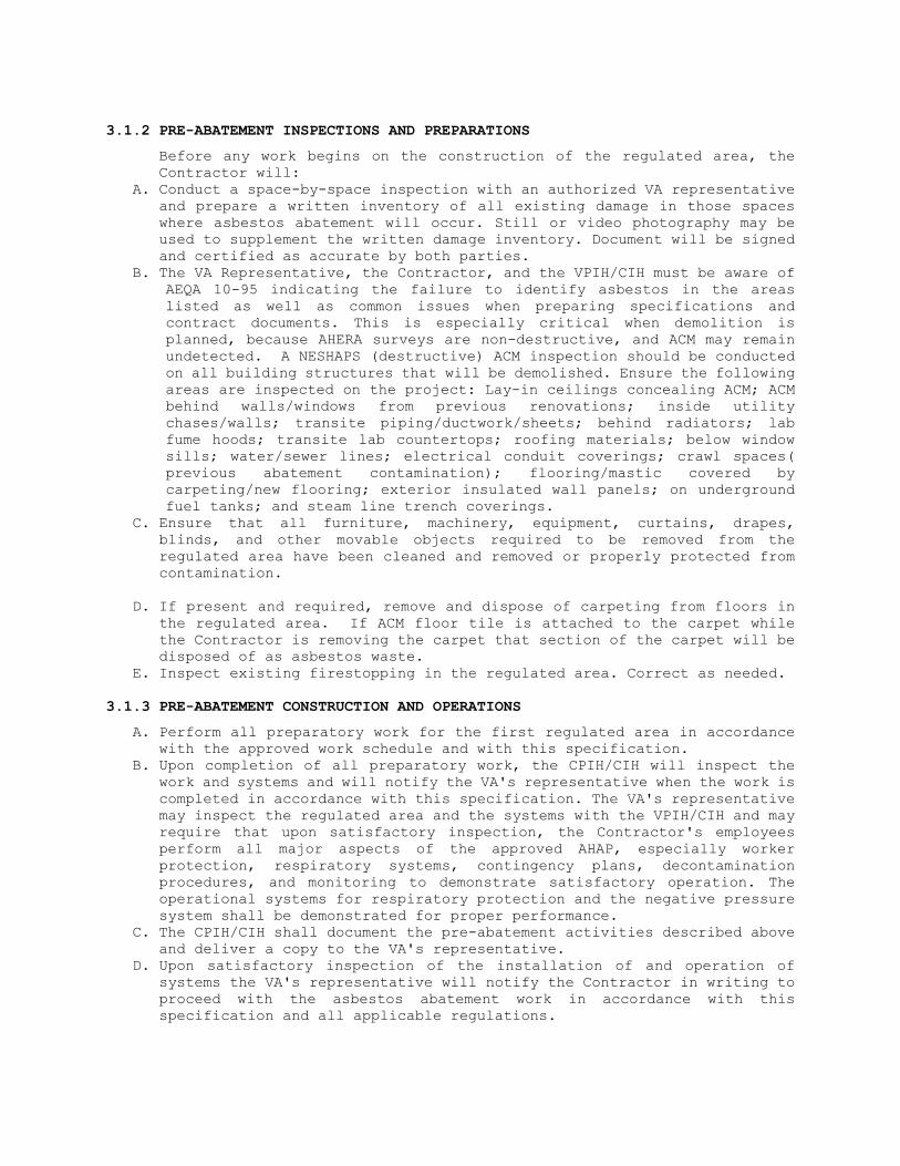
3.1.2 PRE-ABATEMENT INSPECTIONS AND PREPARATIONS
Before any work begins on the construction of the regulated area, the Contractor will:
A. Conduct a space-by-space inspection with an authorized VA representative and prepare a written inventory of all existing damage in those spaces where asbestos abatement will occur. Still or video photography may be used to supplement the written damage inventory. Document will be signed and certified as accurate by both parties.
B. The VA Representative, the Contractor, and the VPIH/CIH must be aware of AEQA 10-95 indicating the failure to identify asbestos in the areas listed as well as common issues when preparing specifications and contract documents. This is especially critical when demolition is planned, because AHERA surveys are non-destructive, and ACM may remain undetected. A NESHAPS (destructive) ACM inspection should be conducted on all building structures that will be demolished. Ensure the following areas are inspected on the project: Lay-in ceilings concealing ACM; ACM behind walls/windows from previous renovations; inside utility chases/walls; transite piping/ductwork/sheets; behind radiators; lab fume hoods; transite lab countertops; roofing materials; below window sills; water/sewer lines; electrical conduit coverings; crawl spaces( previous abatement contamination); flooring/mastic covered by carpeting/new flooring; exterior insulated wall panels; on underground fuel tanks; and steam line trench coverings.
C. Ensure that all furniture, machinery, equipment, curtains, drapes, blinds, and other movable objects required to be removed from the regulated area have been cleaned and removed or properly protected from contamination.
D. If present and required, remove and dispose of carpeting from floors in
the regulated area. If ACM floor tile is attached to the carpet while the Contractor is removing the carpet that section of the carpet will be disposed of as asbestos waste.
E. Inspect existing firestopping in the regulated area. Correct as needed.
3.1.3 PRE-ABATEMENT CONSTRUCTION AND OPERATIONS
A. Perform all preparatory work for the first regulated area in accordance with the approved work schedule and with this specification.
B. Upon completion of all preparatory work, the CPIH/CIH will inspect the work and systems and will notify the VA's representative when the work is completed in accordance with this specification. The VA's representative may inspect the regulated area and the systems with the VPIH/CIH and may require that upon satisfactory inspection, the Contractor's employees perform all major aspects of the approved AHAP, especially worker protection, respiratory systems, contingency plans, decontamination procedures, and monitoring to demonstrate satisfactory operation. The operational systems for respiratory protection and the negative pressure system shall be demonstrated for proper performance.
C. The CPIH/CIH shall document the pre-abatement activities described above and deliver a copy to the VA's representative.
D. Upon satisfactory inspection of the installation of and operation of systems the VA's representative will notify the Contractor in writing to proceed with the asbestos abatement work in accordance with this specification and all applicable regulations.

3.2 REGULATED AREA PREPARATIONS
3.2.1 OSHA DANGER SIGNS
Post OSHA DANGER signs meeting the specifications of OSHA 29 CFR 1926.1101 at any location and approaches to the regulated area where airborne concentrations of asbestos may exceed the PEL. Signs shall be posted at a distance sufficiently far enough away from the regulated area to permit any personnel to read the sign and take the necessary measures to avoid exposure. Additional signs will be posted following construction of the regulated area enclosure.
3.2.2 CONTROLLING ACCESS TO THE REGULATED AREA
Access to the regulated area is allowed only through the personnel decontamination facility (PDF), if required. All other means of access shall be eliminated and OSHA Danger demarcation signs posted as required by OSHA. If the regulated area is adjacent to or within view of an occupied area, provide a visual barrier of 6 mil opaque fire retardant poly sheeting to prevent building occupant observation. If the adjacent area is accessible to the public, the barrier must be solid
3.2.3 SHUT DOWN - LOCK OUT ELECTRICAL
Shut down and lock out/tag out electric power to the regulated area. Provide temporary power and lighting. Insure safe installation including GFCI of temporary power sources and equipment by compliance with all applicable electrical code requirements and OSHA requirements for temporary electrical systems. Electricity shall be provided by the VA.
3.2.4 SHUT DOWN - LOCK OUT HVAC
Shut down and lock out/tag out heating, cooling, and air conditioning system (HVAC) components that are in, supply or pass through the regulated area.
Investigate the regulated area and agree on pre-abatement condition with the VA's representative. Seal all intake and exhaust vents in the regulated area with duct tape and 2 layers of 6-mil poly. Also, seal any seams in system components that pass through the regulated area. Remove all contaminated HVAC system filters and place in labeled 6-mil poly disposal bags for disposal as asbestos waste.
3.2.5 SANITARY FACILITIES
The Contractor shall provide sanitary facilities for abatement personnel and maintain them in a clean and sanitary condition throughout the abatement project.
3.2.6 WATER FOR ABATEMENT The VA will provide water for abatement purposes. The Contractor shall
connect to the existing VA system. The service to the shower(s) shall be supplied with backflow prevention.
3.2.7 PREPARATION PRIOR TO SEALING OFF
Place all tools, materials and equipment needed for working in the regulated area prior to erecting any plastic sheeting. Remove all uncontaminated removable furniture, equipment and/or supplies from the regulated area before commencing work, or completely cover with 2 layers

of 6-mil fire retardant poly sheeting and secure with duct tape. Lock out and tag out any HVAC systems in the regulated area.
3.2.8 CRITICAL BARRIERS
Completely separate any openings into the regulated area from adjacent areas using fire retardant poly at least 6 mils thick and duct tape. Individually seal with 2 layers of 6 mil poly and duct tape all HVAC openings into the regulated area. Individually seal all lighting fixtures, clocks, doors, windows, convectors, speakers, or any other objects in the regulated area. Heat must be shut off any objects covered with poly
3.2.9 FLOOR BARRIERS
If floor removal is not being done, all floors in the regulated area shall be covered with 2 layers of 6 mil fire retardant poly and brought up the wall 12 inches
3.2.10 PRE-CLEANING MOVABLE OBJECTS
Pre-cleaning of ACM contaminated items shall be performed after the enclosure has been erected and negative pressure has been established in the work area. After items have been pre-cleaned and decontaminated, they may be removed from the work area for storage until the completion of abatement in the work area.
Pre-clean all movable objects within the regulated area using a HEPA
filtered vacuum and/or wet cleaning methods as appropriate. After cleaning, these objects shall be removed from the regulated area and carefully stored in an uncontaminated location.
3.2.11 PRE-CLEANING FIXED OBJECTS
Pre-cleaning of ACM contaminated items shall be performed after the enclosure has been erected and negative pressure has been established in the work area
Pre-clean all fixed objects in the regulated area using HEPA filtered
vacuums and/or wet cleaning techniques as appropriate. Careful attention must be paid to machinery behind grills or gratings where access may be difficult but contamination may be significant. Also, pay particular attention to wall, floor and ceiling penetration behind fixed items. After pre-cleaning, enclose fixed objects with 2 layers of 6-mil poly and seal securely in place with duct tape. Objects (e.g., permanent fixtures, shelves, electronic equipment, laboratory tables, sprinklers, alarm systems, closed circuit TV equipment and computer cables) which must remain in the regulated area and that require special ventilation or enclosure requirements should be designated here along with specified means of protection. Contact the manufacturer for special protection requirements.
3.2.12 PRE-CLEANING SURFACES IN THE REGULATED AREA
Pre-cleaning of ACM contaminated items shall be performed after the enclosure has been erected and negative pressure has been established in the work area
Pre-clean all surfaces in the regulated area using HEPA filtered vacuums
and/or wet cleaning methods as appropriate. Do not use any methods that

would raise dust such as dry sweeping or vacuuming with equipment not equipped with HEPA filters. Do not disturb asbestos-containing materials during this pre-cleaning phase.
3.2.13 EXTENSION OF THE REGULATED AREA
If the regulated area barrier is breached in any manner that could allow the passage of asbestos fibers or debris, the Competent Person shall immediately stop work, continue wetting, and proceed to extend the regulated area to enclose the affected area as per procedures described in this specification. If the affected area cannot be enclosed, decontamination measures and cleanup shall start immediately. All personnel shall be isolated from the affected area until decontamination/cleanup is completed as verified by visual inspection and air monitoring. Air monitoring at completion must indicate background levels.
3.3 REMOVAL OF CLASS II FLOORING, ROOFING, AND TRANSITE MATERIALS:
3.3.1 GENERAL
All applicable requirements of OSHA, EPA, and DOT shall be followed during Class II work. Keep materials intact; do not disturb; wet while working with it; wrap as soon as possible with 2 layers of 6 mil plastic for disposal.
3.3.2 REMOVAL OF FLOORING MATERIALS:
A. All requirements of OSHA Flooring agreement provisions shall be followed: 1. The Contractor shall provide enough HEPA negative air machines to effect > - 0.02” WCG pressure. Provide a standby unit in the event of machine failure and/or emergency in an adjacent area. The contractor shall use double the number of machines, based on their calculations, or submit proof their machines operate at stated capacities, at a 2" pressure drop across the filters. 2. Flooring shall be removed intact, as much as possible. Do not rip or tear flooring. 3. Mechanical chipping or sanding is not allowed. 4. Flooring shall be removed with an infra-red heating unit operated by
trained personnel following the manufacturer’s instructions. 5. Wet clean and HEPA vacuum the floor before and after removal of
flooring. 6. Place a 6 mil poly layer 4’ by 10’ adjacent to the regulated area for
use as a decontaminated area. All waste must be contained in the regulated area.
7. Package all waste in 6 mil poly lined fiberboard drums.
3.3.3 REMOVAL OF MASTIC
A. All chemical mastic removers must be low in volatile organic compound (VOC) content, have a flash point greater than 200° Fahrenheit, contain no chlorinated solvents, and comply with California Air Resources Board (CARB) thresholds for VOCs (effective January 1, 2010).
B. A negative air machine as required under flooring removal shall be provided.
C. Follow all manufacturers’ instructions in the use of the mastic removal material. D. Package all waste in 6 mil poly lined fiberboard drums.

E. Prior to application of any liquid material, check the floor for penetrations and seal before removing mastic.
3.4 DISPOSAL OF CLASS II WASTE MATERIAL:
3.4.1 GENERAL
Dispose of waste ACM and debris which is packaged in accordance with these specifications, OSHA, EPA and DOT. The landfill requirements for packaging must also be met. Transport will be in compliance with 49 CFR 100–185 regulations. Disposal shall be done at an approved landfill. Disposal of non-friable ACM shall be done in accordance with applicable regulations.
3.5 PROJECT DECONTAMINATION
3.5.1 GENERAL
A. The VA must be notified at least 24 hours in advance of any waste removed from the containment,
B. The entire work related to project decontamination shall be performed under the close supervision and monitoring of the CPIH/CIH.
C. If the asbestos abatement work is in an area which was contaminated prior to the start of abatement, the decontamination will be done by cleaning the primary barrier poly prior to its removal and cleanings of the surfaces of the regulated area after the primary barrier removal.
D. If the asbestos abatement work is in an area which was uncontaminated prior to the start of abatement, the decontamination will be done by cleaning the primary barrier poly prior to its removal, thus preventing contamination of the building when the regulated area critical barriers are removed.
3.5.2 REGULATED AREA CLEARANCE
Air testing and other requirements which must be met before release of the Contractor and re-occupancy of the regulated area space are specified in Final Testing Procedures.
3.5.3 WORK DESCRIPTION
Decontamination includes the clearance air testing in the regulated area and the decontamination and removal of the enclosures/facilities installed prior to the abatement work including primary/critical barriers, PDF and W/EDF facilities, and negative pressure systems.
3.5.4 PRE-DECONTAMINATION CONDITIONS
A. Before decontamination starts, all ACM waste from the regulated area shall be removed, all waste collected and removed, and the secondary barrier of poly removed and disposed of along with any gross debris generated by the work.
B. At the start of decontamination, the following shall be in place: 1. Critical barriers over all openings consisting of two layers of 6 mil
poly which is the sole barrier between the regulated area and the rest of the building or outside.
2. Decontamination facilities, if required for personnel and equipment in operating condition.

3.5.5 CLEANING:
Carry out a first cleaning of all surfaces of the regulated area including items of remaining poly sheeting, tools, scaffolding, ladders/staging by wet methods and/or HEPA vacuuming. Do not use dry dusting/sweeping/air blowing methods. Use each surface of a wetted cleaning cloth one time only and then dispose of as contaminated waste. Continue this cleaning until there is no visible residue from abated surfaces or poly or other surfaces. Remove all filters in the air handling system and dispose of as ACM waste in accordance with these specifications. The negative pressure system shall remain in operation during this time. Additional cleaning(s) may be needed as determined by the CPIH/VPIH/CIH.
3.6 VISUAL INSPECTION AND AIR CLEARANCE TESTING
3.6.1 GENERAL
Notify the VA representative 24 hours in advance for the performance of the final visual inspection and testing. The final visual inspection and testing will be performed by the VPIH/CIH after the final cleaning.
3.6.2 VISUAL INSPECTION
Final visual inspection will include the entire regulated area, the PDF, all poly sheeting, seals over HVAC openings, doorways, windows, and any other openings. If any debris, residue, dust or any other suspect material is detected, the final cleaning shall be repeated at no cost to the VA. Dust/material samples may be collected and analyzed at no cost to the VA at the discretion of the VPIH/CIH to confirm visual findings. When the regulated area is visually clean the final testing can be done.
3.6.3 AIR CLEARANCE TESTING
A. After an acceptable final visual inspection by the VPIH/CIH and VA Representative, the VPIH/CIH will perform the final clearance testing. Air samples will be collected and analyzed in accordance with procedures for AHERA in this specification. If work is less than 260 lf/160 sf/35 cf, 5 PCM samples shall be collected for clearance and a minimum of one field blank. If work is equal to or more than 260 lf/160 sf/35 cf, AHERA TEM sampling shall be performed for clearance. TEM analysis shall be done in accordance with procedures for EPA AHERA in this specification. If the release criteria are not met, the Contractor shall repeat the final cleaning and continue decontamination procedures until clearance is achieved. All Additional inspection and testing costs will be borne by the Contractor.
B. If release criteria are met, proceed to perform the abatement closeout and to issue the certificate of completion in accordance with these specifications.
3.6.4 FINAL AIR CLEARANCE PROCEDURES
C. Contractor's Release Criteria: Work in a regulated area is complete when the regulated area is visually clean and airborne fiber levels have been reduced to or below 0.01 f/cc as measured by the AHERA PCM protocol, or 70 AHERA structures per square millimeter (s/mm2) by AHERA TEM.
B. Air Monitoring and Final Clearance Sampling: To determine if the elevated airborne fiber counts encountered during abatement operations have been reduced to the specified level, the VPIH/CIH will secure samples and analyze them according to the following procedures:

7. Fibers Counted: “Fibers” referred to in this section shall be either all fibers regardless of composition as counted in the NIOSH 7400 PCM method or asbestos fibers counted using the AHERA TEM method.
2. Aggressive Sampling: All final air testing samples shall be collected using aggressive sampling techniques except where soil is not encapsulated or enclosed. Samples will be collected on 0.8 MCE filters for PCM analysis and 0.45 Polycarbonate filters for TEM. A minimum of 1200 Liters of using calibrated pumps shall be collected for clearance samples. Before pumps are started, initiate aggressive air mixing sampling as detailed in 40 CFR 763 Subpart E (AHERA) Appendix A (III)(B)(7)(d). Air samples will be collected in areas subject to normal air circulation away from corners, obstructed locations, and locations near windows, doors, or vents. After air sampling pumps have been shut off, circulating fans shall be shut off. The negative pressure system shall continue to operate.
3.7 ABATEMENT CLOSEOUT AND CERTIFICATE OF COMPLIANCE
3.7.1 COMPLETION OF ABATEMENT WORK
A. After thorough decontamination, complete asbestos abatement work upon meeting the regulated area clearance criteria and fulfilling the following: 1. Remove all equipment, materials, and debris from the project area. 2. Package and dispose of all asbestos waste as required. 3. Repair or replace all interior finishes damaged during the abatement
work. 4. Fulfill other project closeout requirements as specified elsewhere in
this specification.
3.7.2 CERTIFICATE OF COMPLETION BY CONTRACTOR
The CPIH shall complete and sign the "Certificate of Completion" in accordance with Attachment 1 at the completion of the abatement and decontamination of the regulated area.
3.7.3 WORK SHIFTS
All work shall be done during administrative hours (8:00 AM to 4:30 PM) Monday - Friday excluding Federal Holidays. Any change in the work schedule must be approved in writing by the VA Representative.

ATTACHMENT #1
CERTIFICATE OF COMPLETION
DATE: VA Project #:
PROJECT NAME: Abatement Contractor:
VAMC/ADDRESS:
1. I certify that I have personally inspected, monitored and supervised the abatement work of (specify regulated area or Building):
which took place from / / to / /
2. That throughout the work all applicable requirements/regulations and the VA's specifications were met.
3. That any person who entered the regulated area was protected with the appropriate personal protective equipment and respirator and that they followed the proper entry and exit procedures and the proper operating procedures for the duration of the work.
4. That all employees of the Abatement Contractor engaged in this work were trained in respiratory protection, were experienced with abatement work, had proper medical surveillance documentation, were fit-tested for their respirator, and were not exposed at any time during the work to asbestos without the benefit of appropriate respiratory protection.
5. That I performed and supervised all inspection and testing specified and required by applicable regulations and VA specifications.
6. That the conditions inside the regulated area were always maintained in a safe and healthy condition and the maximum fiber count never exceeded 0.5 f/cc, except as described below.
7. That all abatement work was done in accordance with OSHA requirements and the manufacturer’s recommendations.
CPIH/CIH Signature/Date:
CPIH/CIH Print Name:
Abatement Contractor Signature/Date:
Abatement Contractor Print Name:
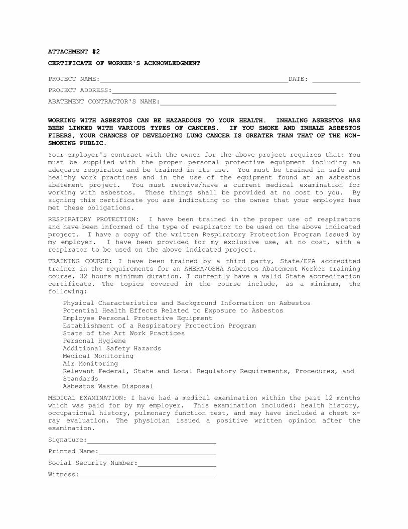
ATTACHMENT #2
CERTIFICATE OF WORKER'S ACKNOWLEDGMENT
PROJECT NAME: DATE:
PROJECT ADDRESS:
ABATEMENT CONTRACTOR'S NAME:
WORKING WITH ASBESTOS CAN BE HAZARDOUS TO YOUR HEALTH. INHALING ASBESTOS HAS BEEN LINKED WITH VARIOUS TYPES OF CANCERS. IF YOU SMOKE AND INHALE ASBESTOS FIBERS, YOUR CHANCES OF DEVELOPING LUNG CANCER IS GREATER THAN THAT OF THE NON-SMOKING PUBLIC.
Your employer's contract with the owner for the above project requires that: You must be supplied with the proper personal protective equipment including an adequate respirator and be trained in its use. You must be trained in safe and healthy work practices and in the use of the equipment found at an asbestos abatement project. You must receive/have a current medical examination for working with asbestos. These things shall be provided at no cost to you. By signing this certificate you are indicating to the owner that your employer has met these obligations.
RESPIRATORY PROTECTION: I have been trained in the proper use of respirators and have been informed of the type of respirator to be used on the above indicated project. I have a copy of the written Respiratory Protection Program issued by my employer. I have been provided for my exclusive use, at no cost, with a respirator to be used on the above indicated project.
TRAINING COURSE: I have been trained by a third party, State/EPA accredited trainer in the requirements for an AHERA/OSHA Asbestos Abatement Worker training course, 32 hours minimum duration. I currently have a valid State accreditation certificate. The topics covered in the course include, as a minimum, the following:
Physical Characteristics and Background Information on Asbestos Potential Health Effects Related to Exposure to Asbestos Employee Personal Protective Equipment Establishment of a Respiratory Protection Program State of the Art Work Practices Personal Hygiene Additional Safety Hazards Medical Monitoring Air Monitoring Relevant Federal, State and Local Regulatory Requirements, Procedures, and Standards Asbestos Waste Disposal
MEDICAL EXAMINATION: I have had a medical examination within the past 12 months which was paid for by my employer. This examination included: health history, occupational history, pulmonary function test, and may have included a chest x-ray evaluation. The physician issued a positive written opinion after the examination.
Signature:
Printed Name:
Social Security Number:
Witness:
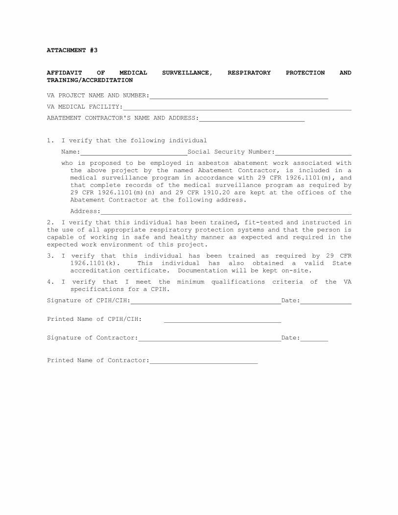
ATTACHMENT #3
AFFIDAVIT OF MEDICAL SURVEILLANCE, RESPIRATORY PROTECTION AND TRAINING/ACCREDITATION
VA PROJECT NAME AND NUMBER:
VA MEDICAL FACILITY:
ABATEMENT CONTRACTOR'S NAME AND ADDRESS:
1. I verify that the following individual
Name: Social Security Number:
who is proposed to be employed in asbestos abatement work associated with the above project by the named Abatement Contractor, is included in a medical surveillance program in accordance with 29 CFR 1926.1101(m), and that complete records of the medical surveillance program as required by 29 CFR 1926.1101(m)(n) and 29 CFR 1910.20 are kept at the offices of the Abatement Contractor at the following address.
Address:
2. I verify that this individual has been trained, fit-tested and instructed in the use of all appropriate respiratory protection systems and that the person is capable of working in safe and healthy manner as expected and required in the expected work environment of this project.
3. I verify that this individual has been trained as required by 29 CFR 1926.1101(k). This individual has also obtained a valid State accreditation certificate. Documentation will be kept on-site.
4. I verify that I meet the minimum qualifications criteria of the VA specifications for a CPIH.
Signature of CPIH/CIH: Date:
Printed Name of CPIH/CIH:
Signature of Contractor: Date:
Printed Name of Contractor:

ATTACHMENT #4
ABATEMENT CONTRACTOR/COMPETENT PERSON(S) REVIEW AND ACCEPTANCE OF THE VA’S ASBESTOS SPECIFICATIONS
VA Project Location:
VA Project #:
VA Project Description:
This form shall be signed by the Asbestos Abatement Contractor Owner and the Asbestos Abatement Contractor’s Competent Person(s) prior to any start of work at the VA related to this Specification. If the Asbestos Abatement Contractor’s/Competent Person(s) has not signed this form, they shall not be allowed to work on-site.
I, the undersigned, have read VA’s Asbestos Specification regarding the asbestos abatement requirements. I understand the requirements of the VA’s Asbestos Specification and agree to follow these requirements as well as all required rules and regulations of OSHA/EPA/DOT and State/Local requirements. I have been given ample opportunity to read the VA’s Asbestos Specification and have been given an opportunity to ask any questions regarding the content and have received a response related to those questions. I do not have any further questions regarding the content, intent and requirements of the VA’s Asbestos Specification.
At the conclusion of the asbestos abatement, I will certify that all asbestos abatement work was done in accordance with the VA’s Asbestos Specification and all ACM was removed properly and no fibrous residue remains on any abated surfaces.
Abatement Contractor Owner’s Signature Date
Abatement Contractor Competent Person(s) Date
- - END- - - -
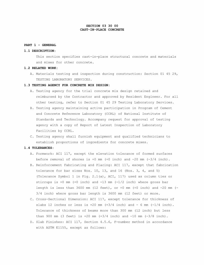
SECTION 03 30 00 CAST-IN-PLACE CONCRETE
PART 1 - GENERAL
1.1 DESCRIPTION:
This section specifies cast-in-place structural concrete and materials
and mixes for other concrete.
1.2 RELATED WORK:
A. Materials testing and inspection during construction: Section 01 45 29,
TESTING LABORATORY SERVICES.
1.3 TESTING AGENCY FOR CONCRETE MIX DESIGN:
A. Testing agency for the trial concrete mix design retained and
reimbursed by the Contractor and approved by Resident Engineer. For all
other testing, refer to Section 01 45 29 Testing Laboratory Services.
B. Testing agency maintaining active participation in Program of Cement
and Concrete Reference Laboratory (CCRL) of National Institute of
Standards and Technology. Accompany request for approval of testing
agency with a copy of Report of Latest Inspection of Laboratory
Facilities by CCRL.
C. Testing agency shall furnish equipment and qualified technicians to
establish proportions of ingredients for concrete mixes.
1.4 TOLERANCES:
A. Formwork: ACI 117, except the elevation tolerance of formed surfaces
before removal of shores is +0 mm (+0 inch) and -20 mm (-3/4 inch).
B. Reinforcement Fabricating and Placing: ACI 117, except that fabrication
tolerance for bar sizes Nos. 10, 13, and 16 (Nos. 3, 4, and 5)
(Tolerance Symbol 1 in Fig. 2.1(a), ACI, 117) used as column ties or
stirrups is +0 mm (+0 inch) and -13 mm (-1/2 inch) where gross bar
length is less than 3600 mm (12 feet), or +0 mm (+0 inch) and -20 mm (-
3/4 inch) where gross bar length is 3600 mm (12 feet) or more.
C. Cross-Sectional Dimension: ACI 117, except tolerance for thickness of
slabs 12 inches or less is +20 mm (+3/4 inch) and - 6 mm (-1/4 inch).
Tolerance of thickness of beams more than 300 mm (12 inch) but less
than 900 mm (3 feet) is +20 mm (+3/4 inch) and -10 mm (-3/8 inch).
D. Slab Finishes: ACI 117, Section 4.5.6, F-number method in accordance
with ASTM E1155, except as follows:

1. Test entire slab surface, including those areas within 600 mm (2
feet) of construction joints and vertical elements that project
through slab surface.
2. Maximum elevation change which may occur within 600 mm (2 feet) of
any column or wall element is 6 mm (0.25 inches).
3. Allow sample measurement lines that are perpendicular to
construction joints to extend past joint into previous placement no
further than 1500 mm (5 feet).
1.5 REGULATORY REQUIREMENTS:
A. ACI SP-66 – ACI Detailing Manual.
B. ACI 318 - Building Code Requirements for Reinforced Concrete.
C. ACI 301 – Standard Specifications for Structural Concrete.
1.6 SUBMITTALS:
A. Submit in accordance with Section 01 33 23, SHOP DRAWINGS, PRODUCT
DATA, and SAMPLES.
B. Shop Drawings: Reinforcing steel: Complete shop drawings
C. Mill Test Reports:
1. Reinforcing Steel.
2. Cement.
D. Manufacturer's Certificates:
1. Abrasive aggregate.
2. Lightweight aggregate for structural concrete.
3. Air-entraining admixture.
4. Chemical admixtures, including chloride ion content.
5. Waterproof paper for curing concrete.
6. Liquid membrane-forming compounds for curing concrete.
7. Non-shrinking grout.
8. Liquid hardener.
9. Waterstops.
10. Expansion joint filler.
11. Adhesive binder.
E. Testing Agency for Concrete Mix Design: Approval request including
qualifications of principals and technicians and evidence of active
participation in program of Cement and Concrete Reference Laboratory
(CCRL) of National Institute of Standards and Technology and copy of
report of latest CCRL, Inspection of Laboratory.

F. Test Report for Concrete Mix Designs: Trial mixes including
water-cement and fly ash ratio curves, concrete mix ingredients, and
admixtures.
G. Shoring and Reshoring Sequence: Submit for approval a shoring and
reshoring sequence for flat slab/flat plate portions, prepared by a
registered Professional Engineer. As a minimum, include timing of form
stripping, reshoring, number of floors to be re-shored and timing of
re-shore removal to serve as an initial outline of procedures subject
to modification as construction progresses. Submit revisions to
sequence, whether initiated by Resident Engineer (see FORMWORK) or
Contractor.
H. Test reports on splitting tensile strength (Fct) of lightweight
concrete.
1.7 DELIVERY, STORAGE, AND HANDLING:
A. Conform to ACI 304. Store aggregate separately for each kind or grade,
to prevent segregation of sizes and avoid inclusion of dirt and other
materials.
B. Deliver cement in original sealed containers bearing name of brand and
manufacturer, and marked with net weight of contents. Store in suitable
watertight building in which floor is raised at least 300 mm (1 foot)
above ground. Store bulk cement and and fly ash in separate suitable
bins.
C. Deliver other packaged materials for use in concrete in original sealed
containers, plainly marked with manufacturer's name and brand, and
protect from damage until used.
1.8 PRE-CONCRETE CONFERENCE:
A. General: At least 15 days prior to submittal of design mixes, conduct a
meeting to review proposed methods of concrete construction to achieve
the required results.
B. Agenda: Includes but is not limited to:
1. Submittals.
2. Coordination of work.
3. Availability of material.
4. Concrete mix design including admixtures.
5. Methods of placing, finishing, and curing.
6. Finish criteria required to obtain required flatness and levelness.
7. Timing of floor finish measurements.
8. Material inspection and testing.

C. Attendees: Include but not limited to representatives of Contractor;
subcontractors involved in supplying, conveying, placing, finishing,
and curing concrete; lightweight aggregate manufacturer; admixture
manufacturers; Resident Engineer; Consulting Engineer; Department of
Veterans Affairs retained testing laboratories for concrete testing and
finish (F-number) verification.
D. Minutes of the meeting: Contractor shall take minutes and type and
distribute the minutes to attendees within five days of the meeting.
1.9 MOCK-UP:
A. In addition to the other specified samples and tests, construct a mock-
up using the materials, reinforcing, forming system and construction
methods proposed for use in exposed architectural concrete.
B. Construct the mock-up with at least a 2.5 m by 2.5 m (8 feet by 8 feet)
exposed surface and suitable foundations. Include the following where
applicable: Control joints, reglets, recesses or other typical
architectural details.
C. Before casting the mock-up, submit full detailed Shop Drawings of the
mock-up formwork for review by the Architect. Perform all necessary
preliminary tests to ensure that concrete used for the mock-up will
exactly match the approved sample in color and texture.
D. Perform the surface treatment proposed for use on one or more areas not
less than 300 mm by 300 mm (1 foot by 1 foot) on the back side of the
mock-up to establish the texture of finish required by the Architect.
Repeat as required until a sample satisfactory to the Architect has
been obtained.
E. Treat the finished front surface of the mock-up to produce a uniform
appearance similar in every respect to the approved sample area.
F. The completed mock-up shall be inspected by the Architect. Failure of
the mock-up to match the approved sample will require the construction
of further mock-ups until approval is obtained. Remove rejected mock-
ups immediately.
G. Maintain the approved mock-ups in good condition at the job site until
all architectural concrete surfaces have been completed and approved by
the Architect. Remove the mock-up from the site after completion of the
above.

1.10 APPLICABLE PUBLICATIONS:
A. Publications listed below form a part of this specification to extent
referenced. Publications are referenced in text by basic designation
only.
B. American Concrete Institute (ACI):
117-10..................Specifications for Tolerances for Concrete
Construction and Materials and Commentary
211.1-91(R2009).........Standard Practice for Selecting Proportions for
Normal, Heavyweight, and Mass Concrete
211.2-98(R2004).........Standard Practice for Selecting Proportions for
Structural Lightweight Concrete
214R-11.................Guide to Evaluation of Strength Test Results of
Concrete
301-10..................Standard Practice for Structural Concrete
304R-00(R2009)..........Guide for Measuring, Mixing, Transporting, and
Placing Concrete
305.1-06................Specification for Hot Weather Concreting
306.1-90(R2002).........Standard Specification for Cold Weather
Concreting
308.1-11................Specification for Curing Concrete
309R-05.................Guide for Consolidation of Concrete
318-11..................Building Code Requirements for Structural
Concrete and Commentary
347-04..................Guide to Formwork for Concrete
SP-66-04................ACI Detailing Manual
C. American National Standards Institute and American Hardboard
Association (ANSI/AHA):
A135.4-2004.............Basic Hardboard
D. American Society for Testing and Materials (ASTM):
A82/A82M-07.............Standard Specification for Steel Wire, Plain,
for Concrete Reinforcement
A185/185M-07............Standard Specification for Steel Welded Wire
Reinforcement, Plain, for Concrete
A615/A615M-09...........Standard Specification for Deformed and Plain
Carbon Steel Bars for Concrete Reinforcement
A653/A653M-11...........Standard Specification for Steel Sheet, Zinc
Coated (Galvanized) or Zinc Iron Alloy Coated
(Galvannealed) by the Hot Dip Process
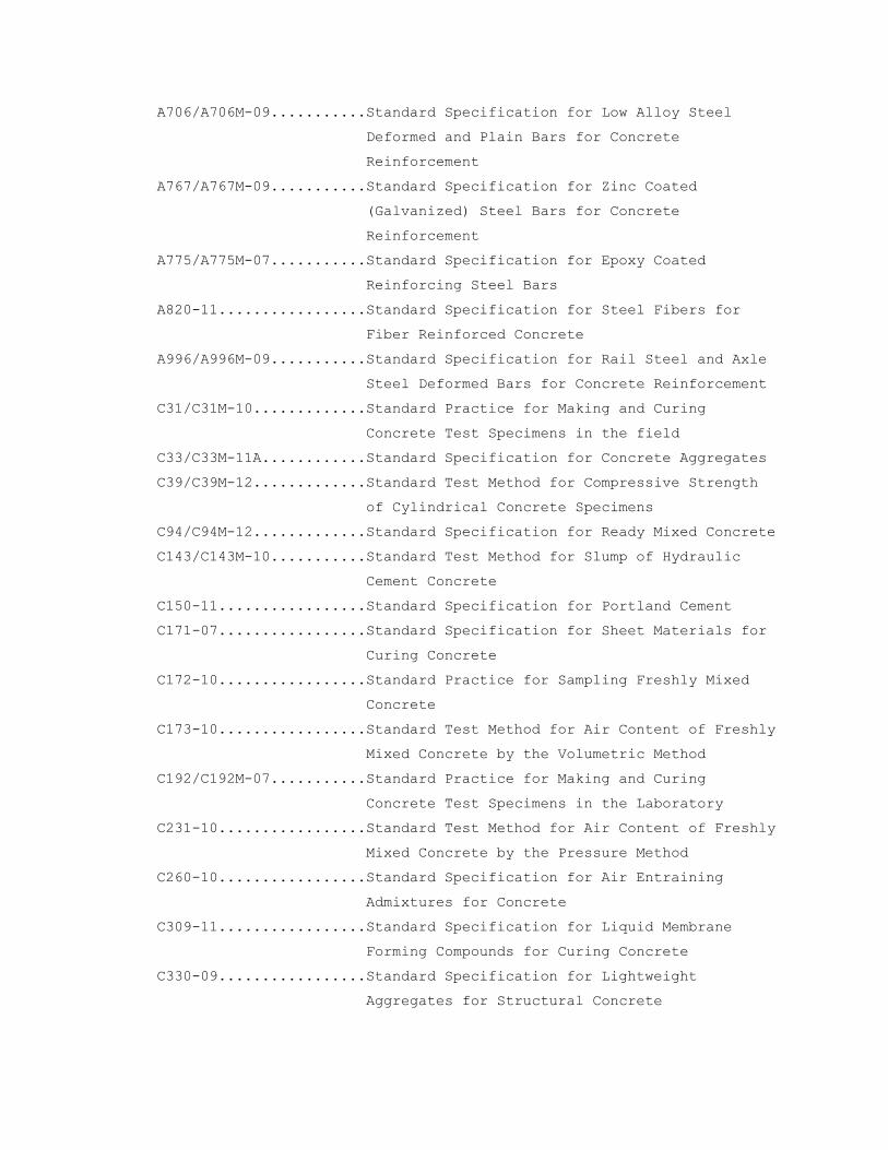
A706/A706M-09...........Standard Specification for Low Alloy Steel
Deformed and Plain Bars for Concrete
Reinforcement
A767/A767M-09...........Standard Specification for Zinc Coated
(Galvanized) Steel Bars for Concrete
Reinforcement
A775/A775M-07...........Standard Specification for Epoxy Coated
Reinforcing Steel Bars
A820-11.................Standard Specification for Steel Fibers for
Fiber Reinforced Concrete
A996/A996M-09...........Standard Specification for Rail Steel and Axle
Steel Deformed Bars for Concrete Reinforcement
C31/C31M-10.............Standard Practice for Making and Curing
Concrete Test Specimens in the field
C33/C33M-11A............Standard Specification for Concrete Aggregates
C39/C39M-12.............Standard Test Method for Compressive Strength
of Cylindrical Concrete Specimens
C94/C94M-12.............Standard Specification for Ready Mixed Concrete
C143/C143M-10...........Standard Test Method for Slump of Hydraulic
Cement Concrete
C150-11.................Standard Specification for Portland Cement
C171-07.................Standard Specification for Sheet Materials for
Curing Concrete
C172-10.................Standard Practice for Sampling Freshly Mixed
Concrete
C173-10.................Standard Test Method for Air Content of Freshly
Mixed Concrete by the Volumetric Method
C192/C192M-07...........Standard Practice for Making and Curing
Concrete Test Specimens in the Laboratory
C231-10.................Standard Test Method for Air Content of Freshly
Mixed Concrete by the Pressure Method
C260-10.................Standard Specification for Air Entraining
Admixtures for Concrete
C309-11.................Standard Specification for Liquid Membrane
Forming Compounds for Curing Concrete
C330-09.................Standard Specification for Lightweight
Aggregates for Structural Concrete

C494/C494M-11...........Standard Specification for Chemical Admixtures
for Concrete
C618-12.................Standard Specification for Coal Fly Ash and Raw
or Calcined Natural Pozzolan for Use in
Concrete
C666/C666M-03(R2008)....Standard Test Method for Resistance of Concrete
to Rapid Freezing and Thawing
C881/C881M-10...........Standard Specification for Epoxy Resin Base
Bonding Systems for Concrete
C1107/1107M-11..........Standard Specification for Packaged Dry,
Hydraulic-Cement Grout (Non-shrink)
C1315-11................Standard Specification for Liquid Membrane
Forming Compounds Having Special Properties for
Curing and Sealing Concrete
D6-95(R2011)............Standard Test Method for Loss on Heating of Oil
and Asphaltic Compounds
D297-93(R2006)..........Standard Methods for Rubber Products Chemical
Analysis
D412—06AE2..............Standard Test Methods for Vulcanized Rubber and
Thermoplastic Elastomers - Tension
D1751-04(R2008).........Standard Specification for Preformed Expansion
Joint Filler for Concrete Paving and Structural
Construction (Non-extruding and Resilient
Bituminous Types)
D4263-83(2012)..........Standard Test Method for Indicating Moisture in
Concrete by the Plastic Sheet Method.
D4397-10................Standard Specification for Polyethylene
Sheeting for Construction, Industrial and
Agricultural Applications
E1155-96(R2008).........Standard Test Method for Determining FF Floor
Flatness and FL Floor Levelness Numbers
F1869-11................Standard Test Method for Measuring Moisture
Vapor Emission Rate of Concrete Subfloor Using
Anhydrous Calcium Chloride.
E. American Welding Society (AWS):
D1.4/D1.4M-11...........Structural Welding Code - Reinforcing Steel
F. Concrete Reinforcing Steel Institute (CRSI):

Handbook 2008
G. National Cooperative Highway Research Program (NCHRP):
Report On...............Concrete Sealers for the Protection of Bridge
Structures
H. U. S. Department of Commerce Product Standard (PS):
PS 1....................Construction and Industrial Plywood
PS 20...................American Softwood Lumber
I. U. S. Army Corps of Engineers Handbook for Concrete and Cement:
CRD C513................Rubber Waterstops
CRD C572................Polyvinyl Chloride Waterstops
PART 2 – PRODUCTS:
2.1 FORMS:
A. Wood: PS 20 free from loose knots and suitable to facilitate finishing
concrete surface specified; tongue and grooved.
B. Plywood: PS-1 Exterior Grade B-B (concrete-form) 16 mm (5/8 inch), or
20 mm (3/4 inch) thick for unlined contact form. B-B High Density
Concrete Form Overlay optional.
C. Metal for Concrete Rib-Type Construction: Steel (removal type) of
suitable weight and form to provide required rigidity.
D. Permanent Steel Form for Concrete Slabs: Corrugated, ASTM A653, Grade
E, and Galvanized, ASTM A653, G90. Provide venting where insulating
concrete fill is used.
E. Corrugated Fiberboard Void Boxes: Double faced, completely impregnated
with paraffin and laminated with moisture resistant adhesive, size as
shown. Design forms to support not less than 48 KPa (1000 psf) and not
lose more than 15 percent of their original strength after being
completely submerged in water for 24 hours and then air dried.
F. Form Lining:
1. Hardboard: ANSI/AHA A135.4, Class 2 with one (S1S) smooth side)
2. Plywood: Grade B-B Exterior (concrete-form) not less than 6 mm (1/4
inch) thick.
3. Plastic, fiberglass, or elastomeric capable of reproducing the
desired pattern or texture.
G. Concrete products shall comply with following standards for biobased
materials:

Material Type Percent by Weight
Concrete Penetrating Liquid 79 percent biobased material
Concrete form Release Agent 87 percent biobased material
Concrete Sealer 11 percent biobased material
The minimum-content standards are based on the weight (not the volume)
of the material.
H. Form Ties: Develop a minimum working strength of 13.35 kN (3000 pounds)
when fully assembled. Ties shall be adjustable in length to permit
tightening of forms and not have any lugs, cones, washers to act as
spreader within form, nor leave a hole larger than 20 mm (3/4 inch)
diameter, or a depression in exposed concrete surface, or leave metal
closer than 40 mm (1 1/2 inches) to concrete surface. Wire ties not
permitted. Cutting ties back from concrete face not permitted.
2.2 MATERIALS:
A. Portland Cement: ASTM C150 Type I or II.
B. Fly Ash: ASTM C618, Class C or F including supplementary optional
requirements relating to reactive aggregates and alkalies, and loss on
ignition (LOI) not to exceed 5 percent.
C. Coarse Aggregate: ASTM C33.
1. Size 67 or Size 467 may be used for footings and walls over 300 mm
(12 inches) thick.
2. Coarse aggregate for applied topping, encasement of steel columns,
and metal pan stair fill shall be Size 7.
3. Maximum size of coarse aggregates not more than one-fifth of
narrowest dimension between sides of forms, one-third of depth of
slabs, nor three-fourth of minimum clear spacing between reinforcing
bars.
D. Lightweight Aggregates for Structural Concrete: ASTM C330, Table 1.
Maximum size of aggregate not larger than one-fifth of narrowest
dimension between forms, nor three-fourth of minimum clear distance
between reinforcing bars. Contractor to furnish certified report to
verify that aggregate is sound and durable, and has a durability factor
of not less than 80 based on 300 cycles of freezing and thawing when
tested in accordance with ASTM C666.
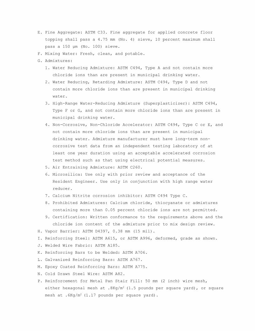
E. Fine Aggregate: ASTM C33. Fine aggregate for applied concrete floor
topping shall pass a 4.75 mm (No. 4) sieve, 10 percent maximum shall
pass a 150 µm (No. 100) sieve.
F. Mixing Water: Fresh, clean, and potable.
G. Admixtures:
1. Water Reducing Admixture: ASTM C494, Type A and not contain more
chloride ions than are present in municipal drinking water.
2. Water Reducing, Retarding Admixture: ASTM C494, Type D and not
contain more chloride ions than are present in municipal drinking
water.
3. High-Range Water-Reducing Admixture (Superplasticizer): ASTM C494,
Type F or G, and not contain more chloride ions than are present in
municipal drinking water.
4. Non-Corrosive, Non-Chloride Accelerator: ASTM C494, Type C or E, and
not contain more chloride ions than are present in municipal
drinking water. Admixture manufacturer must have long-term non-
corrosive test data from an independent testing laboratory of at
least one year duration using an acceptable accelerated corrosion
test method such as that using electrical potential measures.
5. Air Entraining Admixture: ASTM C260.
6. Microsilica: Use only with prior review and acceptance of the
Resident Engineer. Use only in conjunction with high range water
reducer.
7. Calcium Nitrite corrosion inhibitor: ASTM C494 Type C.
8. Prohibited Admixtures: Calcium chloride, thiocyanate or admixtures
containing more than 0.05 percent chloride ions are not permitted.
9. Certification: Written conformance to the requirements above and the
chloride ion content of the admixture prior to mix design review.
H. Vapor Barrier: ASTM D4397, 0.38 mm (15 mil).
I. Reinforcing Steel: ASTM A615, or ASTM A996, deformed, grade as shown.
J. Welded Wire Fabric: ASTM A185.
K. Reinforcing Bars to be Welded: ASTM A706.
L. Galvanized Reinforcing Bars: ASTM A767.
M. Epoxy Coated Reinforcing Bars: ASTM A775.
N. Cold Drawn Steel Wire: ASTM A82.
P. Reinforcement for Metal Pan Stair Fill: 50 mm (2 inch) wire mesh,
either hexagonal mesh at .8Kg/m2 (1.5 pounds per square yard), or square
mesh at .6Kg/m2 (1.17 pounds per square yard).

Q. Supports, Spacers, and Chairs: Types which will hold reinforcement in
position shown in accordance with requirements of ACI 318 except as
specified.
R. Expansion Joint Filler: ASTM D1751.
S. Sheet Materials for Curing Concrete: ASTM C171.
T. Liquid Membrane-forming Compounds for Curing Concrete: ASTM C309, Type
I, with fugitive dye, and shall meet the requirements of ASTM
C1315.Compound shall be compatible with scheduled surface treatment,
such as paint and resilient tile, and shall not discolor concrete
surface.
U. Abrasive Aggregate: Aluminum oxide grains or emery grits.
V. Liquid Hardener and Dustproofer: Fluosilicate solution of magnesium
fluosilicate or zinc fluosilicate. Magnesium and zinc may be used
separately or in combination as recommended by manufacturer. Use only
on exposed slab. Do not use where floor is covered with resilient
flooring, paint or other finish coating.
W. Moisture Vapor Emissions & Alkalinity Control Sealer: 100% active
colorless aqueous siliconate solution concrete surface.
1. ASTM C1315 Type 1 Class A, and ASTM C309 Type 1 Class A, penetrating
product to have no less than 34% solid content, leaving no sheen,
volatile organic compound (VOC) content rating as required to suite
regulatory requirements. The product shall have at least a five (5)
year documented history in controlling moisture vapor emission from
damaging floor covering, compatible with all finish materials.
2. MVE 15-Year Warranty:
a. When a floor covering is installed on a below grade, on grade, or
above grade concrete slab treated with Moisture Vapor Emissions &
Alkalinity Control Sealer according to manufacturer’s
instruction, sealer manufacturer shall warrant the floor covering
system against failure due to moisture vapor migration or
moisture-born contaminates for a period of fifteen (15) years
from the date of original installation. The warranty shall cover
all labor and materials needed to replace all floor covering that
fails due to moisture vapor emission & moisture born
contaminates.
X. Penetrating Sealer: For use on parking garage ramps and decks. High
penetration silane sealer providing minimum 95 percent screening per
National Cooperative Highway Research Program (NCHRP) No. 244 standards

for chloride ion penetration resistance. Requires moist (non-membrane)
curing of slab.
Y. Non-Shrink Grout:
1. ASTM C1107, pre-mixed, produce a compressive strength of at least 18
MPa at three days and 35 MPa (5000 psi) at 28 days. Furnish test
data from an independent laboratory indicating that the grout when
placed at a fluid consistency shall achieve 95 percent bearing under
a 1200 mm x 1200 mm (4 foot by 4 foot) base plate.
2. Where high fluidity or increased placing time is required, furnish
test data from an independent laboratory indicating that the grout
when placed at a fluid consistency shall achieve 95 percent under an
450 mm x 900 mm (18 inch by 36 inch) base plate.
Z. Adhesive Binder: ASTM C881.
AA. Waterstops:
1. Polyvinyl Chloride Waterstop: CRD C572.
2. Rubber Waterstops: CRD C513.
3. Bentonite Waterstop: Flexible strip of bentonite 25 mm x 20 mm (1
inch by 3/4 inch), weighing 8.7 kg/m (5.85 lbs. per foot) composed
of Butyl Rubber Hydrocarbon (ASTM D297), Bentonite (SS-S-210-A) and
Volatile Matter (ASTM D6).
4. Non-Metallic Hydrophilic: Swellable strip type compound of polymer
modified chloroprene rubber that swells upon contact with water
shall conform to ASTM D412 as follows: Tensile strength 420 psi
minimum; ultimate elongation 600 percent minimum. Hardness shall be
50 minimum on the type A durameter and the volumetric expansion
ratio in in 70 deg water shall be 3 to 1 minimum.
BB. Porous Backfill: Crushed stone or gravel graded from 25 mm to 20 mm (1
inch to 3/4 inch).
CC. Fibers:
1. Synthetic Fibers: Monofilament or fibrillated polypropylene fibers
for secondary reinforcing of concrete members. Use appropriate
length and 0.9 kg/m3 (1.5 lb. per cubic yard). Product shall have a
UL rating.
2. Steel Fibers: ASTM A820, Type I cold drawn, high tensile steel wire
for use as primary reinforcing in slab-on-grade. Minimum dosage rate
18 kg/m3 (30 lb. per cubic yard).
DD. Epoxy Joint Filler: Two component, 100 percent solids compound, with a
minimum shore D hardness of 50.

EE. Bonding Admixture: Non-rewettable, polymer modified, bonding compound.
FF. Architectural Concrete: For areas designated as architectural concrete
on the Contract Documents, use colored cements and specially selected
aggregates as necessary to produce a concrete of a color and finish
which exactly matches the designated sample panel.
2.3 CONCRETE MIXES:
A. Mix Designs: Proportioned in accordance with Section 5.3,
"Proportioning on the Basis of Field Experience and/or Trial Mixtures"
of ACI 318.
1. If trial mixes are used, make a set of at least 6 cylinders in
accordance with ASTM C192 for test purposes from each trial mix;
test three for compressive strength at 7 days and three at 28 days.
2. Submit a report of results of each test series, include a detailed
listing of the proportions of trial mix or mixes, including cement,
fly ash, admixtures, weight of fine and coarse aggregate per m3
(cubic yard) measured dry rodded and damp loose, specific gravity,
fineness modulus, percentage of moisture, air content, water-cement
and fly ash ratio, and consistency of each cylinder in terms of
slump. Include dry unit weight of lightweight structural concrete.
3. Prepare a curve showing relationship between water-cement and fly
ash ratio at 7-day and 28-day compressive strengths. Plot each curve
using at least three specimens.
4. If the field experience method is used, submit complete standard
deviation analysis.
B. Fly Ash Testing: Submit certificate verifying conformance with ASTM 618
initially with mix design and for each truck load of fly ash delivered
from source. Submit test results performed within 6 months of submittal
date. Notify Resident Engineer immediately when change in source is
anticipated.
1. Testing Laboratory used for fly ash certification/testing shall
participate in the Cement and Concrete Reference Laboratory (CCRL)
program. Submit most recent CCRL inspection report.
C. After approval of mixes no substitution in material or change in
proportions of approval mixes may be made without additional tests and
approval of Resident Engineer or as specified. Making and testing of
preliminary test cylinders may be carried on pending approval of cement
and fly ash, providing Contractor and manufacturer certify that
ingredients used in making test cylinders are the same. Resident

Engineer may allow Contractor to proceed with depositing concrete for
certain portions of work, pending final approval of cement and fly ash
and approval of design mix.
D. Cement Factor: Maintain minimum cement factors in Table I regardless of
compressive strength developed above minimums. Use Fly Ash as an
admixture with 20% replacement by weight in all structural work.
Increase this replacement to 40% for mass concrete, and reduce it to
10% for drilled piers and caissons. Fly ash shall not be used in high-
early mix design.

TABLE I - CEMENT AND WATER FACTORS FOR CONCRETE
Concrete Strength Non-Air-Entrained
Air-Entrained
Min. 28 Day Comp. Str.
MPa (psi)
Min. Cement kg/m3 (lbs/c.
yd)
Max. Water Cement Ratio
Min. Cement
kg/m3 (lbs/c. yd)
Max. Water Cement Ratio
35 (5000)1,3 375 (630) 0.45 385 (650) 0.40
30 (4000)1,3 325 (550) 0.55 340 (570) 0.50
25 (3000)1,3 280 (470) 0.65 290 (490) 0.55
25 (3000)1,2 300 (500) * 310 (520) *
1. If trial mixes are used, the proposed mix design shall achieve a
compressive strength 8.3 MPa (1200 psi) in excess of f'c. For
concrete strengths above 35 Mpa (5000 psi), the proposed mix design
shall achieve a compressive strength 9.7 MPa (1400 psi) in excess of
f’c.
2. Lightweight Structural Concrete. Pump mixes may require higher
cement values.
3. For concrete exposed to high sulfate content soils maximum water
cement ratio is 0.44.
4. Determined by Laboratory in accordance with ACI 211.1 for normal
concrete or ACI 211.2 for lightweight structural concrete.
E. Maximum Slump: Maximum slump, as determined by ASTM C143 with
tolerances as established by ASTM C94, for concrete to be vibrated
shall be as shown in Table II.
TABLE II - MAXIMUM SLUMP, MM (INCHES)*
Type of Construction Normal Weight Concrete
Lightweight Structural Concrete
Reinforced Footings and Substructure Walls
75mm (3 inches) 75 mm (3 inches)
Slabs, Beams, Reinforced Walls, and Building Columns
100 mm (4 inches)
100 mm (4 inches)
F. Slump may be increased by the use of the approved high-range water-
reducing admixture (superplasticizer). Tolerances as established by
ASTM C94. Concrete containing the high-range-water-reducing admixture
may have a maximum slump of 225 mm (9 inches). The concrete shall

arrive at the job site at a slump of 50 mm to 75 mm (2 inches to 3
inches), and 75 mm to 100 mm (3 inches to 4 inches) for lightweight
concrete. This should be verified, and then the high-range-water-
reducing admixture added to increase the slump to the approved level.
G. Air-Entrainment: Air-entrainment of normal weight concrete shall
conform with Table III. Air-entrainment of lightweight structural
concrete shall conform with Table IV. Determine air content by either
ASTM C173 or ASTM C231.
TABLE III - TOTAL AIR CONTENT FOR VARIOUS SIZES OF COARSE AGGREGATES (NORMAL CONCRETE)
Nominal Maximum Size of Total Air Content
Coarse Aggregate, mm (Inches) Percentage by Volume
10 mm (3/8 in).6 to 10 13 mm (1/2 in).5 to 9
20 mm (3/4 in).4 to 8 25 mm (1 in).3-1/2 to 6-1/2
40 mm (1 1/2 in).3 to 6
TABLE IV AIR CONTENT OF LIGHTWEIGHT STRUCTURAL CONCRETE
Nominal Maximum size of Total Air Content
Coarse Aggregate, mm’s (Inches) Percentage by Volume
Greater than 10 mm (3/8 in) 4 to 8
10 mm (3/8 in) or less 5 to 9
H. High early strength concrete, made with Type III cement or Type I
cement plus non-corrosive accelerator, shall have a 7-day compressive
strength equal to specified minimum 28-day compressive strength for
concrete type specified made with standard Portland cement.
I. Lightweight structural concrete shall not weigh more than air-dry unit
weight shown. Air-dry unit weight determined on 150 mm by 300 mm (6
inch by 12 inch) test cylinders after seven days standard moist curing
followed by 21 days drying at 23 degrees C 1.7 degrees C (73.4 3
degrees Fahrenheit), and 50 (plus or minus 7) percent relative
humidity. Use wet unit weight of fresh concrete as basis of control in
field.
J. Concrete slabs placed at air temperatures below 10 degrees C (50 degrees
Fahrenheit) use non-corrosive, non-chloride accelerator. Concrete
required to be air entrained use approved air entraining admixture.
Pumped concrete, synthetic fiber concrete, architectural concrete,
concrete required to be watertight, and concrete with a water/cement

ratio below 0.50 use high-range water-reducing admixture
(superplasticizer).
K. Durability: Use air entrainment for exterior exposed concrete subjected
to freezing and thawing and other concrete shown or specified. For air
content requirements see Table III or Table IV.
L. Enforcing Strength Requirements: Test as specified in Section 01 45 29,
TESTING LABORATORY SERVICES, during the progress of the work. Seven-day
tests may be used as indicators of 28-day strength. Average of any
three 28-day consecutive strength tests of laboratory-cured specimens
representing each type of concrete shall be equal to or greater than
specified strength. No single test shall be more than 3.5 MPa (500 psi)
below specified strength. Interpret field test results in accordance
with ACI 214. Should strengths shown by test specimens fall below
required values, Resident Engineer may require any one or any
combination of the following corrective actions, at no additional cost
to the Government:
1. Require changes in mix proportions by selecting one of the other
appropriate trial mixes or changing proportions, including cement
content, of approved trial mix.
2. Require additional curing and protection.
3. If five consecutive tests fall below 95 percent of minimum values
given in Table I or if test results are so low as to raise a
question as to the safety of the structure, Resident Engineer may
direct Contractor to take cores from portions of the structure. Use
results from cores tested by the Contractor retained testing agency
to analyze structure.
4. If strength of core drilled specimens falls below 85 percent of
minimum value given in Table I, Resident Engineer may order load
tests, made by Contractor retained testing agency, on portions of
building so affected. Load tests in accordance with ACI 318 and
criteria of acceptability of concrete under test as given therein.
5. Concrete work, judged inadequate by structural analysis, by results
of load test, or for any reason, shall be reinforced with additional
construction or replaced, if directed by the Resident Engineer.
2.4 BATCHING AND MIXING:
A. General: Concrete shall be "Ready-Mixed" and comply with ACI 318 and
ASTM C94, except as specified. Batch mixing at the site is permitted.
Mixing process and equipment must be approved by Resident Engineer.

With each batch of concrete, furnish certified delivery tickets listing
information in Paragraph 16.1 and 16.2 of ASTM C94. Maximum delivery
temperature of concrete is 380C (100 degrees Fahrenheit). Minimum
delivery temperature as follows:
Atmospheric Temperature Minimum Concrete Temperature
-1. degrees to 4.4 degrees C
(30 degrees to 40 degrees F)
15.6 degrees C (60 degrees F.)
-17 degrees C to -1.1 degrees C (0 degrees to 30 degrees F.)
21 degrees C (70 degrees F.)
1. Services of aggregate manufacturer's representative shall be
furnished during the design of trial mixes and as requested by the
Resident Engineer for consultation during batching, mixing, and
placing operations of lightweight structural concrete. Services will
be required until field controls indicate that concrete of required
quality is being furnished. Representative shall be thoroughly
familiar with the structural lightweight aggregate, adjustment and
control of mixes to produce concrete of required quality.
Representative shall assist and advise Resident Engineer.
PART 3 – EXECUTION
3.1 FORMWORK:
A. General: Design in accordance with ACI 347 is the responsibility of the
Contractor. The Contractor shall retain a registered Professional
Engineer to design the formwork, shores, and reshores.
1. Form boards and plywood forms may be reused for contact surfaces of
exposed concrete only if thoroughly cleaned, patched, and repaired
and Resident Engineer approves their reuse.
2. Provide forms for concrete footings unless Resident Engineer
determines forms are not necessary.
3. Corrugated fiberboard forms: Place forms on a smooth firm bed, set
tight, with no buckled cartons to prevent horizontal displacement,
and in a dry condition when concrete is placed.
B. Treating and Wetting: Treat or wet contact forms as follows:
1. Coat plywood and board forms with non-staining form sealer. In hot
weather, cool forms by wetting with cool water just before concrete
is placed.
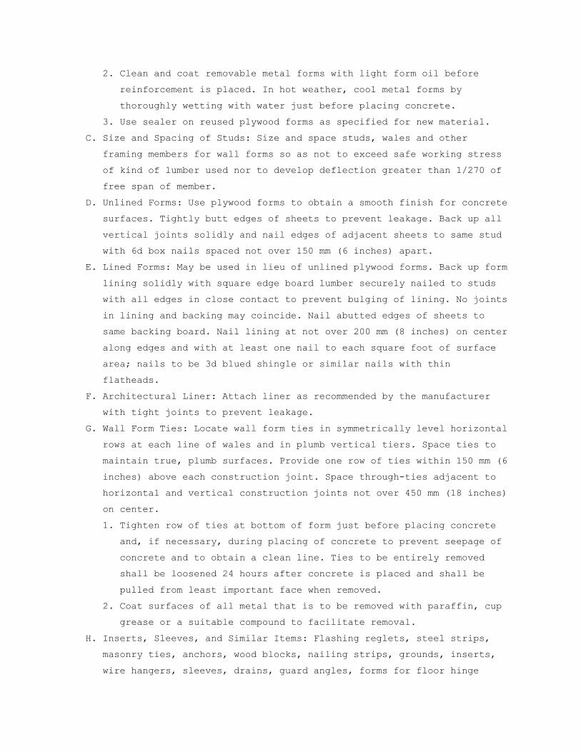
2. Clean and coat removable metal forms with light form oil before
reinforcement is placed. In hot weather, cool metal forms by
thoroughly wetting with water just before placing concrete.
3. Use sealer on reused plywood forms as specified for new material.
C. Size and Spacing of Studs: Size and space studs, wales and other
framing members for wall forms so as not to exceed safe working stress
of kind of lumber used nor to develop deflection greater than 1/270 of
free span of member.
D. Unlined Forms: Use plywood forms to obtain a smooth finish for concrete
surfaces. Tightly butt edges of sheets to prevent leakage. Back up all
vertical joints solidly and nail edges of adjacent sheets to same stud
with 6d box nails spaced not over 150 mm (6 inches) apart.
E. Lined Forms: May be used in lieu of unlined plywood forms. Back up form
lining solidly with square edge board lumber securely nailed to studs
with all edges in close contact to prevent bulging of lining. No joints
in lining and backing may coincide. Nail abutted edges of sheets to
same backing board. Nail lining at not over 200 mm (8 inches) on center
along edges and with at least one nail to each square foot of surface
area; nails to be 3d blued shingle or similar nails with thin
flatheads.
F. Architectural Liner: Attach liner as recommended by the manufacturer
with tight joints to prevent leakage.
G. Wall Form Ties: Locate wall form ties in symmetrically level horizontal
rows at each line of wales and in plumb vertical tiers. Space ties to
maintain true, plumb surfaces. Provide one row of ties within 150 mm (6
inches) above each construction joint. Space through-ties adjacent to
horizontal and vertical construction joints not over 450 mm (18 inches)
on center.
1. Tighten row of ties at bottom of form just before placing concrete
and, if necessary, during placing of concrete to prevent seepage of
concrete and to obtain a clean line. Ties to be entirely removed
shall be loosened 24 hours after concrete is placed and shall be
pulled from least important face when removed.
2. Coat surfaces of all metal that is to be removed with paraffin, cup
grease or a suitable compound to facilitate removal.
H. Inserts, Sleeves, and Similar Items: Flashing reglets, steel strips,
masonry ties, anchors, wood blocks, nailing strips, grounds, inserts,
wire hangers, sleeves, drains, guard angles, forms for floor hinge

boxes, inserts or bond blocks for elevator guide rails and supports,
and other items specified as furnished under this and other sections of
specifications and required to be in their final position at time
concrete is placed shall be properly located, accurately positioned,
and built into construction, and maintained securely in place.
1. Locate inserts or hanger wires for furred and suspended ceilings
only in bottom of concrete joists, or similar concrete member of
overhead concrete joist construction.
2. Install sleeves, inserts and similar items for mechanical services
in accordance with drawings prepared specially for mechanical
services. Contractor is responsible for accuracy and completeness
of drawings and shall coordinate requirements for mechanical
services and equipment.
3. Do not install sleeves in beams, joists or columns except where
shown or permitted by Resident Engineer. Install sleeves in beams,
joists, or columns that are not shown, but are permitted by the
Resident Engineer, and require no structural changes, at no
additional cost to the Government.
4. Minimum clear distance of embedded items such as conduit and pipe is
at least three times diameter of conduit or pipe, except at stub-ups
and other similar locations.
5. Provide recesses and blockouts in floor slabs for door closers and
other hardware as necessary in accordance with manufacturer's
instructions.
I. Construction Tolerances:
1. Set and maintain concrete formwork to assure erection of completed
work within tolerances specified and to accommodate installation of
other rough and finish materials. Accomplish remedial work necessary
for correcting excessive tolerances. Erected work that exceeds
specified tolerance limits shall be remedied or removed and
replaced, at no additional cost to the Government.
2. Permissible surface irregularities for various classes of materials
are defined as "finishes" in specification sections covering
individual materials. They are to be distinguished from tolerances
specified which are applicable to surface irregularities of
structural elements.

3.2 PLACING REINFORCEMENT:
A. General: Details of concrete reinforcement in accordance with ACI 318
unless otherwise shown.
B. Placing: Place reinforcement conforming to CRSI DA4, unless otherwise
shown.
1. Place reinforcing bars accurately and tie securely at intersections
and splices with 1.6 mm (16 gauge) black annealed wire. Use epoxy-
coated tie wire with epoxy-coated reinforcing. Secure reinforcing
bars against displacement during the placing of concrete by spacers,
chairs, or other similar supports. Portions of supports, spacers,
and chairs in contact with formwork shall be made of plastic in
areas that will be exposed when building is occupied. Type, number,
and spacing of supports conform to ACI 318. Where concrete slabs are
placed on ground, use concrete blocks or other non-corrodible
material of proper height, for support of reinforcement. Use of
brick or stone supports will not be permitted.
2. Lap welded wire fabric at least 1 1/2 mesh panels plus end extension
of wires not less than 300 mm (12 inches) in structural slabs. Lap
welded wire fabric at least 1/2 mesh panels plus end extension of
wires not less than 150 mm (6 inches) in slabs on grade.
3. Splice column steel at no points other than at footings and floor
levels unless otherwise shown.
C. Spacing: Minimum clear distances between parallel bars, except in
columns and multiple layers of bars in beams shall be equal to nominal
diameter of bars. Minimum clear spacing is 25 mm (1 inch) or 1-1/3
times maximum size of coarse aggregate.
D. Splicing: Splices of reinforcement made only as required or shown or
specified. Accomplish splicing as follows:
1. Lap splices: Do not use lap splices for bars larger than Number 36
(Number 11). Minimum lengths of lap as shown.
2. Welded splices: Splicing by butt-welding of reinforcement permitted
providing the weld develops in tension at least 125 percent of the
yield strength (fy) for the bars. Welding conform to the
requirements of AWS D1.4. Welded reinforcing steel conform to the
chemical analysis requirements of AWS D1.4.
a. Submit test reports indicating the chemical analysis to establish
weldability of reinforcing steel.

b. Submit a field quality control procedure to insure proper
inspection, materials and welding procedure for welded splices.
c. Department of Veterans Affairs retained testing agency shall test
a minimum of three splices, for compliance, locations selected by
Resident Engineer.
3. Mechanical Splices: Develop in tension and compression at least 125
percent of the yield strength (fy) of the bars. Stresses of
transition splices between two reinforcing bar sizes based on area
of smaller bar. Provide mechanical splices at locations indicated.
Use approved exothermic, tapered threaded coupling, or swaged and
threaded sleeve. Exposed threads and swaging in the field not
permitted.
a. Initial qualification: In the presence of Resident Engineer, make
three test mechanical splices of each bar size proposed to be
spliced. Department of Veterans Affairs retained testing
laboratory will perform load test.
b. During installation: Furnish, at no additional cost to the
Government, one companion (sister) splice for every 50 splices
for load testing. Department of Veterans Affairs retained testing
laboratory will perform the load test.
E. Bending: Bend bars cold, unless otherwise approved. Do not field bend
bars partially embedded in concrete, except when approved by Resident
Engineer.
F. Cleaning: Metal reinforcement, at time concrete is placed, shall be
free from loose flaky rust, mud, oil, or similar coatings that will
reduce bond.
G. Future Bonding: Protect exposed reinforcement bars intended for bonding
with future work by wrapping with felt and coating felt with a
bituminous compound unless otherwise shown.
3.3 VAPOR BARRIER:
A. Except where membrane waterproofing is required, interior concrete slab
on grade shall be placed on a continuous vapor barrier.
1. Place 100 mm (4 inches) of fine granular fill over the vapor barrier
to act as a blotter for concrete slab.
2. Vapor barrier joints lapped 150 mm (6 inches) and sealed with
compatible waterproof pressure-sensitive tape.
3. Patch punctures and tears.

3.4 SLABS RECEIVING RESILIENT COVERING
A. Slab shall be allowed to cure for 6 weeks minimum prior to placing
resilient covering. After curing, slab shall be tested by the
Contractor for moisture in accordance with ASTM D4263 or ASTM F1869.
Moisture content shall be less than 3 pounds per 1000 sf prior to
placing covering.
B. In lieu of curing for 6 weeks, Contractor has the option, at his own
cost, to utilize the Moisture Vapor Emissions & Alkalinity Control
Sealer as follows:
1. Sealer is applied on the day of the concrete pour or as soon as
harsh weather permits, prior to any other chemical treatments for
concrete slabs either on grade, below grade or above grade receiving
resilient flooring, such as, sheet vinyl, vinyl composition tile,
rubber, wood flooring, epoxy coatings and overlays.
2. Manufacturer’s representative will be on the site the day of
concrete pour to install or train its application and document. He
shall return on every application thereafter to verify that proper
procedures are followed.
a. Apply Sealer to concrete slabs as soon as final finishing
operations are complete and the concrete has hardened
sufficiently to sustain floor traffic without damage.
b. Spray apply Sealer at the rate of 20 m2 (200 square feet) per
gallon. Lightly broom product evenly over the substrate and
product has completely penetrated the surface.
c. If within two (2) hours after initial application areas are
subjected to heavy rainfall and puddling occurs, reapply Sealer
product to these areas as soon as weather condition permits.
3.5 CONSTRUCTION JOINTS:
A. Unless otherwise shown, location of construction joints to limit
individual placement shall not exceed 24,000 mm (80 feet) in any
horizontal direction, except slabs on grade which shall have
construction joints shown. Allow 48 hours to elapse between pouring
adjacent sections unless this requirement is waived by Resident
Engineer.
B. Locate construction joints in suspended floors near the quarter-point
of spans for slabs, beams or girders, unless a beam intersects a girder
at center, in which case joint in girder shall be offset a distance

equal to twice width of beam. Provide keys and inclined dowels as
shown. Provide longitudinal keys as shown.
C. Place concrete for columns slowly and in one operation between joints.
Install joints in concrete columns at underside of deepest beam or
girder framing into column.
D. Allow 2 hours to elapse after column is cast before concrete of
supported beam, girder or slab is placed. Place girders, beams, grade
beams, column capitals, brackets, and haunches at the same time as slab
unless otherwise shown.
E. Install polyvinyl chloride or rubber water seals, as shown in
accordance with manufacturer's instructions, to form continuous
watertight seal.
3.6 EXPANSION JOINTS AND CONTRACTION JOINTS:
A. Clean expansion joint surfaces before installing premolded filler and
placing adjacent concrete.
B. Install polyvinyl chloride or rubber water seals, as shown in
accordance with manufacturer's instructions, to form continuous
watertight seal.
C. Provide contraction (control) joints in floor slabs as indicated on the
contract drawings. Joints shall be either formed or saw cut, to the
indicated depth after the surface has been finished. Complete saw
joints within 4 to 12 hours after concrete placement. Protect joints
from intrusion of foreign matter.
3.7 PLACING CONCRETE:
A. Preparation:
1. Remove hardened concrete, wood chips, shavings and other debris from
forms.
2. Remove hardened concrete and foreign materials from interior
surfaces of mixing and conveying equipment.
3. Have forms and reinforcement inspected and approved by Resident
Engineer before depositing concrete.
4. Provide runways for wheeling equipment to convey concrete to point
of deposit. Keep equipment on runways which are not supported by or
bear on reinforcement. Provide similar runways for protection of
vapor barrier on coarse fill.
B. Bonding: Before depositing new concrete on or against concrete which
has been set, thoroughly roughen and clean existing surfaces of
laitance, foreign matter, and loose particles.

1. Preparing surface for applied topping:
a. Remove laitance, mortar, oil, grease, paint, or other foreign
material by sand blasting. Clean with vacuum type equipment to
remove sand and other loose material.
b. Broom clean and keep base slab wet for at least four hours before
topping is applied.
c. Use a thin coat of one part Portland cement, 1.5 parts fine sand,
bonding admixture; and water at a 50: 50 ratio and mix to achieve
the consistency of thick paint. Apply to a damp base slab by
scrubbing with a stiff fiber brush. New concrete shall be placed
while the bonding grout is still tacky.
C. Conveying Concrete: Convey concrete from mixer to final place of
deposit by a method which will prevent segregation. Method of conveying
concrete is subject to approval of Resident Engineer.
D. Placing: For special requirements see Paragraphs, HOT WEATHER and COLD
WEATHER.
1. Do not place concrete when weather conditions prevent proper
placement and consolidation, or when concrete has attained its
initial set, or has contained its water or cement content more than
1 1/2 hours.
2. Deposit concrete in forms as near as practicable in its final
position. Prevent splashing of forms or reinforcement with concrete
in advance of placing concrete.
3. Do not drop concrete freely more than 3000 mm (10 feet) for concrete
containing the high-range water-reducing admixture
(superplasticizer) or 1500 mm (5 feet) for conventional concrete.
Where greater drops are required, use a tremie or flexible spout
(canvas elephant trunk), attached to a suitable hopper.
4. Discharge contents of tremies or flexible spouts in horizontal
layers not exceeding 500 mm (20 inches) in thickness, and space
tremies such as to provide a minimum of lateral movement of
concrete.
5. Continuously place concrete until an entire unit between
construction joints is placed. Rate and method of placing concrete
shall be such that no concrete between construction joints will be
deposited upon or against partly set concrete, after its initial set
has taken place, or after 45 minutes of elapsed time during concrete
placement.

6. On bottom of members with severe congestion of reinforcement,
deposit 25 mm (1 inch) layer of flowing concrete containing the
specified high-range water-reducing admixture (superplasticizer).
Successive concrete lifts may be a continuation of this concrete or
concrete with a conventional slump.
7. Concrete on metal deck:
a. Concrete on metal deck shall be minimum thickness shown. Allow
for deflection of steel beams and metal deck under the weight of
wet concrete in calculating concrete quantities for slab.
1) The Contractor shall become familiar with deflection
characteristics of structural frame to include proper amount
of additional concrete due to beam/deck deflection.
E. Consolidation: Conform to ACI 309. Immediately after depositing, spade
concrete next to forms, work around reinforcement and into angles of
forms, tamp lightly by hand, and compact with mechanical vibrator
applied directly into concrete at approximately 450 mm (18 inch)
intervals. Mechanical vibrator shall be power driven, hand operated
type with minimum frequency of 5000 cycles per minute having an
intensity sufficient to cause flow or settlement of concrete into
place. Vibrate concrete to produce thorough compaction, complete
embedment of reinforcement and concrete of uniform and maximum density
without segregation of mix. Do not transport concrete in forms by
vibration.
1. Use of form vibration shall be approved only when concrete sections
are too thin or too inaccessible for use of internal vibration.
2. Carry on vibration continuously with placing of concrete. Do not
insert vibrator into concrete that has begun to set.
3.8 HOT WEATHER:
Follow the recommendations of ACI 305 or as specified to prevent
problems in the manufacturing, placing, and curing of concrete that can
adversely affect the properties and serviceability of the hardened
concrete. Methods proposed for cooling materials and arrangements for
protecting concrete shall be made in advance of concrete placement and
approved by Resident Engineer.
3.9 COLD WEATHER:
Follow the recommendations of ACI 306 or as specified to prevent
freezing of concrete and to permit concrete to gain strength properly.
Use only the specified non-corrosive, non-chloride accelerator. Do not

use calcium chloride, thiocyantes or admixtures containing more than
0.05 percent chloride ions. Methods proposed for heating materials and
arrangements for protecting concrete shall be made in advance of
concrete placement and approved by Resident Engineer.
3.10 PROTECTION AND CURING:
A. Conform to ACI 308: Initial curing shall immediately follow the
finishing operation. Protect exposed surfaces of concrete from
premature drying, wash by rain and running water, wind, mechanical
injury, and excessively hot or cold temperatures. Keep concrete not
covered with membrane or other curing material continuously wet for at
least 7 days after placing, except wet curing period for high-early-
strength concrete shall be not less than 3 days. Keep wood forms
continuously wet to prevent moisture loss until forms are removed. Cure
exposed concrete surfaces as described below. Other curing methods may
be used if approved by Resident Engineer.
1. Liquid curing and sealing compounds: Apply by power-driven spray or
roller in accordance with the manufacturer’s instructions. Apply
immediately after finishing. Maximum coverage 10m2/L (400 square feet
per gallon) on steel troweled surfaces and 7.5m2/L (300 square feet
per gallon) on floated or broomed surfaces for the curing/sealing
compound.
2. Plastic sheets: Apply as soon as concrete has hardened sufficiently
to prevent surface damage. Utilize widest practical width sheet and
overlap adjacent sheets 50 mm (2 inches). Tightly seal joints with
tape.
3. Paper: Utilize widest practical width paper and overlap adjacent
sheets 50 mm (2 inches). Tightly seal joints with sand, wood planks,
pressure-sensitive tape, mastic or glue.
3.11 REMOVAL OF FORMS:
A. Remove in a manner to assure complete safety of structure after the
following conditions have been met.
1. Where structure as a whole is supported on shores, forms for beams
and girder sides, columns, and similar vertical structural members
may be removed after 24 hours, provided concrete has hardened
sufficiently to prevent surface damage and curing is continued
without any lapse in time as specified for exposed surfaces.
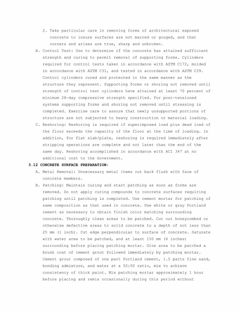
2. Take particular care in removing forms of architectural exposed
concrete to insure surfaces are not marred or gouged, and that
corners and arises are true, sharp and unbroken.
B. Control Test: Use to determine if the concrete has attained sufficient
strength and curing to permit removal of supporting forms. Cylinders
required for control tests taken in accordance with ASTM C172, molded
in accordance with ASTM C31, and tested in accordance with ASTM C39.
Control cylinders cured and protected in the same manner as the
structure they represent. Supporting forms or shoring not removed until
strength of control test cylinders have attained at least 70 percent of
minimum 28-day compressive strength specified. For post-tensioned
systems supporting forms and shoring not removed until stressing is
completed. Exercise care to assure that newly unsupported portions of
structure are not subjected to heavy construction or material loading.
C. Reshoring: Reshoring is required if superimposed load plus dead load of
the floor exceeds the capacity of the floor at the time of loading. In
addition, for flat slab/plate, reshoring is required immediately after
stripping operations are complete and not later than the end of the
same day. Reshoring accomplished in accordance with ACI 347 at no
additional cost to the Government.
3.12 CONCRETE SURFACE PREPARATION:
A. Metal Removal: Unnecessary metal items cut back flush with face of
concrete members.
B. Patching: Maintain curing and start patching as soon as forms are
removed. Do not apply curing compounds to concrete surfaces requiring
patching until patching is completed. Use cement mortar for patching of
same composition as that used in concrete. Use white or gray Portland
cement as necessary to obtain finish color matching surrounding
concrete. Thoroughly clean areas to be patched. Cut out honeycombed or
otherwise defective areas to solid concrete to a depth of not less than
25 mm (1 inch). Cut edge perpendicular to surface of concrete. Saturate
with water area to be patched, and at least 150 mm (6 inches)
surrounding before placing patching mortar. Give area to be patched a
brush coat of cement grout followed immediately by patching mortar.
Cement grout composed of one part Portland cement, 1.5 parts fine sand,
bonding admixture, and water at a 50:50 ratio, mix to achieve
consistency of thick paint. Mix patching mortar approximately 1 hour
before placing and remix occasionally during this period without
addition of water. Compact mortar into place and screed slightly higher
than surrounding surface. After initial shrinkage has occurred, finish
to match color and texture of adjoining surfaces. Cure patches as
specified for other concrete. Fill form tie holes which extend entirely
through walls from unexposed face by means of a pressure gun or other
suitable device to force mortar through wall. Wipe excess mortar off
exposed face with a cloth.
C. Upon removal of forms, clean vertical concrete surface that is to
receive bonded applied cementitious application with wire brushes or by
sand blasting to remove unset material, laitance, and loose particles
to expose aggregates to provide a clean, firm, granular surface for
bond of applied finish.
3.13 CONCRETE FINISHES:
A. Vertical and Overhead Surface Finishes:
1. Unfinished areas: Vertical and overhead concrete surfaces exposed in
pipe basements, elevator and dumbwaiter shafts, pipe spaces, pipe
trenches, above suspended ceilings, manholes, and other unfinished
areas will not require additional finishing.
2. Interior and exterior exposed areas to be painted: Remove fins,
burrs and similar projections on surfaces flush, and smooth by
mechanical means approved by Resident Engineer, and by rubbing
lightly with a fine abrasive stone or hone. Use ample water during
rubbing without working up a lather of mortar or changing texture of
concrete.
3. Interior and exterior exposed areas finished: Give a grout finish of
uniform color and smooth finish treated as follows:
a. After concrete has hardened and laitance, fins and burrs removed,
scrub concrete with wire brushes. Clean stained concrete surfaces
by use of a hone stone.
b. Apply grout composed of one part of Portland cement, one part
fine sand, smaller than a 600 µm (No. 30) sieve. Work grout into
surface of concrete with cork floats or fiber brushes until all
pits, and honeycombs are filled.
c. After grout has hardened slightly, but while still plastic,
scrape grout off with a sponge rubber float and, about 1 hour
later, rub concrete vigorously with burlap to remove any excess
grout remaining on surfaces.

d. In hot, dry weather use a fog spray to keep grout wet during
setting period. Complete finish of area in same day. Make limits
of finished areas at natural breaks in wall surface. Leave no
grout on concrete surface overnight.
4. Textured: Finish as specified. Maximum quantity of patched area 0.2
m2 (2 square feet) in each 93 m2 (1000 square feet) of textured
surface.
B. Slab Finishes:
1. Monitoring and Adjustment: Provide continuous cycle of placement,
measurement, evaluation and adjustment of procedures to produce
slabs within specified tolerances. Monitor elevations of structural
steel in key locations before and after concrete placement to
establish typical deflection patterns for the structural steel.
Determine elevations of cast-in-place slab soffits prior to removal
of shores. Provide information to Resident Engineer and floor
consultant for evaluation and recommendations for subsequent
placements.
2. Set perimeter forms to serve as screed using either optical or laser
instruments. For slabs on grade, wet screeds may be used to
establish initial grade during strike-off, unless Resident Engineer
determines that the method is proving insufficient to meet required
finish tolerances and directs use of rigid screed guides. Where wet
screeds are allowed, they shall be placed using grade stakes set by
optical or laser instruments. Use rigid screed guides, as opposed to
wet screeds, to control strike-off elevation for all types of
elevated (non slab-on-grade) slabs. Divide bays into halves or
thirds by hard screeds. Adjust as necessary where monitoring of
previous placements indicates unshored structural steel deflections
to other than a level profile.
3. Place slabs monolithically. Once slab placement commences, complete
finishing operations within same day. Slope finished slab to floor
drains where they occur, whether shown or not.
4. Use straightedges specifically made for screeding, such as hollow
magnesium straightedges or power strike-offs. Do not use pieces of
dimensioned lumber. Strike off and screed slab to a true surface at
required elevations. Use optical or laser instruments to check
concrete finished surface grade after strike-off. Repeat strike-off
as necessary. Complete screeding before any excess moisture or

bleeding water is present on surface. Do not sprinkle dry cement on
the surface.
5. Immediately following screeding, and before any bleed water appears,
use a 3000 mm (10 foot) wide highway straightedge in a cutting and
filling operation to achieve surface flatness. Do not use bull
floats or darbys, except that darbying may be allowed for narrow
slabs and restricted spaces.
6. Wait until water sheen disappears and surface stiffens before
proceeding further. Do not perform subsequent operations until
concrete will sustain foot pressure with maximum of 6 mm (1/4 inch)
indentation.
7. Scratch Finish: Finish base slab to receive a bonded applied
cementitious application as indicated above, except that bull floats
and darbys may be used. Thoroughly coarse wire broom within two
hours after placing to roughen slab surface to insure a permanent
bond between base slab and applied materials.
8. Float Finish: Slabs to receive unbonded toppings, steel trowel
finish, fill, mortar setting beds, or a built-up roof, and ramps,
stair treads, platforms (interior and exterior), and equipment pads
shall be floated to a smooth, dense uniform, sandy textured finish.
During floating, while surface is still soft, check surface for
flatness using a 3000 mm (10 foot) highway straightedge. Correct
high spots by cutting down and correct low spots by filling in with
material of same composition as floor finish. Remove any surface
projections and re-float to a uniform texture.
9. Steel Trowel Finish: Concrete surfaces to receive resilient floor
covering or carpet, monolithic floor slabs to be exposed to view in
finished work, future floor roof slabs, applied toppings, and other
interior surfaces for which no other finish is indicated. Steel
trowel immediately following floating. During final troweling, tilt
steel trowel at a slight angle and exert heavy pressure to compact
cement paste and form a dense, smooth surface. Finished surface
shall be smooth, free of trowel marks, and uniform in texture and
appearance.
10. Broom Finish: Finish exterior slabs, ramps, and stair treads with a
bristle brush moistened with clear water after surfaces have been
floated. Brush in a direction transverse to main traffic. Match
texture approved by Resident Engineer from sample panel.

11. Finished slab flatness (FF) and levelness (FL) values comply with
the following minimum requirements:
a. Areas covered with carpeting, or not specified otherwise in b.
below:
1) Slab on Grade:
a) Specified overall value FF 25/FL 20
b) Minimum local value FF 17/FL 15
2) Level suspended slabs (shored until after testing) and topping
slabs:
a) Specified overall value FF 25/FL 20
b) Minimum local value FF 17/FL 15
3) Unshored suspended slabs:
a) Specified overall value FF 25
b) Minimum local value FF 17
4) Level tolerance such that 80 percent of all points fall within
a 20 mm (3/4 inch) envelope +10 mm, -10 mm (+3/8 inch, -3/8
inch) from the design elevation.
b. Areas that will be exposed, receive thin-set tile or resilient
flooring, or roof areas designed as future floors:
1) Slab on grade:
a) Specified overall value FF 36/FL 20
b) Minimum local value FF 24/FL 15
2) Level suspended slabs (shored until after testing) and topping
slabs
a) Specified overall value FF 30/FL 20
b) Minimum local value FF 24/FL 15
3) Unshored suspended slabs:
a) Specified overall value FF 30
b) Minimum local value FF 24
4) Level tolerance such that 80 percent of all points fall within
a 20 mm (3/4 inch) envelope +10 mm, -10 mm (+3/8 inch, -3/8
inch) from the design elevation.
c. "Specified overall value" is based on the composite of all
measured values in a placement derived in accordance with ASTM
E1155.
d. "Minimum local value" (MLV) describes the flatness or levelness
below which repair or replacement is required. MLV is based on
the results of an individual placement and applies to a minimum

local area. Minimum local area boundaries may not cross a
construction joint or expansion joint. A minimum local area will
be bounded by construction and/or control joints, or by column
lines and/or half-column lines, whichever is smaller.
12. Measurements
a. Department of Veterans Affairs retained testing laboratory will
take measurements as directed by Resident Engineer, to verify
compliance with FF, FL, and other finish requirements.
Measurements will occur within 72 hours after completion of
concrete placement (weekends and holidays excluded). Make
measurements before shores or forms are removed to insure the
"as-built" levelness is accurately assessed. Profile data for
above characteristics may be collected using a laser level or any
Type II apparatus (ASTM E1155, "profileograph" or "dipstick").
Contractor's surveyor shall establish reference elevations to be
used by Department of Veterans Affairs retained testing
laboratory.
b. Contractor not experienced in using FF and FL criteria is
encouraged to retain the services of a floor consultant to assist
with recommendations concerning adjustments to slab thicknesses,
finishing techniques, and procedures on measurements of the
finish as it progresses in order to achieve the specific flatness
and levelness numbers.
13. Acceptance/ Rejection:
a. If individual slab section measures less than either of specified
minimum local FF/FL numbers, that section shall be rejected and
remedial measures shall be required. Sectional boundaries may be
set at construction and contraction (control) joints, and not
smaller than one-half bay.
b. If composite value of entire slab installation, combination of
all local results, measures less than either of specified overall
FF/FL numbers, then whole slab shall be rejected and remedial
measures shall be required.
14. Remedial Measures for Rejected Slabs: Correct rejected slab areas by
grinding, planing, surface repair with underlayment compound or
repair topping, retopping, or removal and replacement of entire
rejected slab areas, as directed by Resident Engineer, until a slab
finish constructed within specified tolerances is accepted.

3.14 SURFACE TREATMENTS:
A. Use on exposed concrete floors and concrete floors to receive carpeting
except those specified to receive non-slip finish.
B. Liquid Densifier/Sealer: Apply in accordance with manufacturer's
directions just prior to completion of construction.
C. Non-Slip Finish: Except where safety nosing and tread coverings are
shown, apply non-slip abrasive aggregate to treads and platforms of
concrete steps and stairs, and to surfaces of exterior concrete ramps
and platforms. Broadcast aggregate uniformly over concrete surface at
rate of application of 8% per 1/10th m2 (7.5 percent per square foot) of
area. Trowel concrete surface to smooth dense finish. After curing, rub
treated surface with abrasive brick and water to slightly expose
abrasive aggregate.
3.15 APPLIED TOPPING:
A. Separate concrete topping on floor base slab of thickness and strength
shown. Topping mix shall have a maximum slump of 200 mm (8 inches) for
concrete containing a high-range water-reducing admixture
(superplasticizer) and 100 mm (4 inches) for conventional mix. Neatly
bevel or slope at door openings and at slabs adjoining spaces not
receiving an applied finish.
B. Placing: Place continuously until entire section is complete, struck
off with straightedge, leveled with a highway straightedge or highway
bull float, floated and troweled by machine to a hard dense finish.
Slope to floor drains as required. Do not start floating until free
water has disappeared and no water sheen is visible. Allow drying of
surface moisture naturally. Do not hasten by "dusting" with cement or
sand.
3.16 RESURFACING FLOORS:
Remove existing flooring areas to receive resurfacing to expose
existing structural slab and extend not less than 25 mm (1 inch) below
new finished floor level. Prepare exposed structural slab surface by
roughening, broom cleaning, and dampening. Apply specified bonding
grout. Place topping while the bonding grout is still tacky.
3.17 RETAINING WALLS:
A. Use air-entrained concrete.
B. Expansion and contraction joints, waterstops, weep holes, reinforcement
and railing sleeves installed and constructed as shown.

C. Exposed surfaces finished to match adjacent concrete surfaces, new or
existing.
D. Place porous backfill as shown.
3.18 PRECAST CONCRETE ITEMS:
Precast concrete items, not specified elsewhere. Cast using 25 MPa
(3000 psi) air-entrained concrete to shapes and dimensions shown.
Finish to match corresponding adjacent concrete surfaces. Reinforce
with steel for safe handling and erection.
- - - E N D - - -

SECTION 03 30 53 (SHORT-FORM) CAST-IN-PLACE CONCRETE
PART 1 - GENERAL
1.1 DESCRIPTION:
This section specifies cast-in-place structural concrete and material
and mixes for other concrete.
1.2 RELATED WORK:
A. Materials testing and inspection during construction: Section 01 45 29,
TESTING LABORATORY SERVICES.
1.3 TOLERANCES:
A. ACI 117.
B. Slab Finishes: ACI 117, F-number method in accordance with ASTM E1155.
1.4 REGULATORY REQUIREMENTS:
A. ACI SP-66 ACI Detailing Manual
B. ACI 318 - Building Code Requirements for Reinforced Concrete.
1.5 SUBMITTALS:
A. Submit in accordance with Section 01 33 23, SHOP DRAWINGS, PRODUCT
DATA, AND SAMPLES.
B. Concrete Mix Design.
C. Shop Drawings: Reinforcing steel: Complete shop drawings.
D. Manufacturer's Certificates: Air-entraining admixture, chemical
admixtures, curing compounds.
1.6 APPLICABLE PUBLICATIONS:
A. Publications listed below form a part of this specification to extent
referenced. Publications are referenced in text by basic designation
only.
B. American Concrete Institute (ACI):
117R-06.................Tolerances for Concrete Construction and
Materials
211.1-91(R2002).........Proportions for Normal, Heavyweight, and Mass
Concrete
211.2-98(R2004).........Proportions for Structural Lightweight Concrete
301-05..................Specification for Structural Concrete
305R-06.................Hot Weather Concreting
306R-2002...............Cold Weather Concreting
SP-66-04 ...............ACI Detailing Manual

318/318R-05.............Building Code Requirements for Reinforced
Concrete
347R-04.................Guide to Formwork for Concrete
C. American Society for Testing And Materials (ASTM):
A185-07.................Steel Welded Wire, Fabric, Plain for Concrete
Reinforcement
A615/A615M-08...........Deformed and Plain Billet-Steel Bars for
Concrete Reinforcement
A996/A996M-06...........Standard Specification for Rail-Steel and Axle-
Steel Deformed Bars for Concrete Reinforcement
C31/C31M-08.............Making and Curing Concrete Test Specimens in
the Field
C33-07..................Concrete Aggregates
C39/C39M-05.............Compressive Strength of Cylindrical Concrete
Specimens
C94/C94M-07.............Ready-Mixed Concrete
C143/C143M-05...........Standard Test Method for Slump of Hydraulic
Cement Concrete
C150-07.................Portland Cement
C171-07.................Sheet Material for Curing Concrete
C172-07.................Sampling Freshly Mixed Concrete
C173-07.Air Content of Freshly Mixed Concrete by the Volumetric Method
C192/C192M-07...........Making and Curing Concrete Test Specimens in
the Laboratory
C231-08.................Air Content of Freshly Mixed Concrete by the
Pressure Method
C260-06.................Air-Entraining Admixtures for Concrete
C330-05.................Lightweight Aggregates for Structural Concrete
C494/C494M-08...........Chemical Admixtures for Concrete
C618-08.................Coal Fly Ash and Raw or Calcined Natural
Pozzolan for Use in Concrete
D1751-04.Preformed Expansion Joint Fillers for Concrete Paving and
Structural Construction (Non-extruding and
Resilient Bituminous Types)
D4397-02................Polyethylene Sheeting for Construction,
Industrial and Agricultural Applications
E1155-96(2008)..........Determining FF Floor Flatness and FL Floor
Levelness Numbers

PART 2 - PRODUCTS
2.2 MATERIALS:
A. Portland Cement: ASTM C150, Type I or II.
B. Fly Ash: ASTM C618, Class C or F including supplementary optional
requirements relating to reactive aggregates and alkalis, and loss on
ignition (LOI) not to exceed 5 percent.
C. Coarse Aggregate: ASTM C33, Size 67. Size 467 may be used for footings
and walls over 300 mm (12 inches) thick. Coarse aggregate for applied
topping and metal pan stair fill shall be Size 7.
D. Fine Aggregate: ASTM C33.
E. Lightweight Aggregate for Structural Concrete: ASTM C330, Table 1
F. Mixing Water: Fresh, clean, and potable.
G. Air-Entraining Admixture: ASTM C260.
H. Chemical Admixtures: ASTM C494.
J. Reinforcing Steel: ASTM A615 or ASTM A996, deformed. See structural
drawings for grade.
K. Welded Wire Fabric: ASTM A185.
2.3 CONCRETE MIXES:
A. Design of concrete mixes using materials specified shall be the
responsibility of the Contractor as set forth under Option C of ASTM
C94.
B. Compressive strength at 28 days shall be not less than 3000 psi.
C. Establish strength of concrete by testing prior to beginning concreting
operation. Test consists of average of three cylinders made and cured
in accordance with ASTM C192 and tested in accordance with ASTM C39.
D. Maximum slump for vibrated concrete is 100 mm (4 inches) tested in
accordance with ASTM C143.
E. Cement and water factor (See Table I):
TABLE I - CEMENT AND WATER FACTORS FOR CONCRETE
Concrete: Strength Non-Air-Entrained Air-Entrained
Min. 28 Day Comp. Str.
MPa (psi)
Min. Cement
kg/m3 (lbs/c. yd)
Max. Water Cement Ratio
Min. Cement
kg/m3 (lbs/c. yd)
Max. Water
Cement Ratio
35 (5000)1,3 375 (630) 0.45 385 (650) 0.40
30 (4000)1,3 325 (550) 0.55 340 (570) 0.50
25 (3000)1,3 280 (470) 0.65 290 (490) 0.55

25 (3000)1,2 300 (500) * 310 (520) *
1. If trial mixes are used, the proposed mix design shall achieve a
compressive strength 8.3 MPa (1200 psi) in excess of f'c. For
concrete strengths above 35 Mpa (5000 psi), the proposed mix design
shall achieve a compressive strength 9.7 MPa (1400 psi) in excess of
f’c.
2.4 BATCHING & MIXING:
A. Store, batch, and mix materials as specified in ASTM C94.
1. Job-Mixed: Concrete mixed at job site shall be mixed in a batch
mixer in manner specified for stationary mixers in ASTM C94.
2. Ready-Mixed: Ready-mixed concrete comply with ASTM C94, except use
of non-agitating equipment for transporting concrete to the site
will not be permitted. With each load of concrete delivered to
project, ready-mixed concrete producer shall furnish, in duplicate,
certification as required by ASTM C94.
PART 3 - EXECUTION
3.1 REINFORCEMENT:
Details of concrete reinforcement, unless otherwise shown, in
accordance with ACI 318 and ACI SP-66. Support and securely tie
reinforcing steel to prevent displacement during placing of concrete.
3.2 PLACING CONCRETE:
A. Before placing new concrete on or against concrete which has set,
existing surfaces shall be roughened and cleaned free from all
laitance, foreign matter, and loose particles.
B. Convey concrete from mixer to final place of deposit by method which
will prevent segregation or loss of ingredients. Do not deposit in work
concrete that has attained its initial set or has contained its water
or cement more than 1 1/2 hours. Do not allow concrete to drop freely
more than 1500 mm (5 feet) in unexposed work nor more than 900 mm (3
feet) in exposed work. Place and consolidate concrete in horizontal
layers not exceeding 300 mm (12 inches) in thickness. Consolidate
concrete by spading, rodding, and mechanical vibrator. Do not secure
vibrator to forms or reinforcement. Vibration shall be carried on
continuously with placing of concrete.
3.3 PROTECTION AND CURING:
Protect exposed surfaces of concrete from premature drying, wash by
rain or running water, wind, mechanical injury, and excessively hot or

cold temperature. Curing method shall be subject to approval by
Resident Engineer.
3.4 FINISHES:
A. Slab Finishes:
1. Steel Trowel Finish: Applied toppings, concrete surfaces to receive
resilient floor covering or carpet, future floor roof and all
monolithic concrete floor slabs exposed in finished work and for
which no other finish is shown or specified shall be steel troweled.
Final steel troweling to secure a smooth, dense surface shall be
delayed as long as possible, generally when the surface can no
longer be dented with finger. During final troweling, tilt steel
trowel at a slight angle and exert heavy pressure on trowel to
compact cement paste and form a dense, smooth surface. Finished
surface shall be free of trowel marks, uniform in texture and
appearance.
2. Finished slab flatness (FF) and levelness (FL) values comply with
the following minimum requirements:
Slab on grade & Shored suspended slabs
Unshored suspended slabs
Specified overall value FF 25/FL 20 Specified overall value FF 25
Minimum local value FF 17/FL 15 Minimum local value FF 17
- - - E N D - - -

SECTION 05 12 00 STRUCTURAL STEEL FRAMING
PART 1 - GENERAL
1.1 DESCRIPTION:
This section specifies structural steel shown and classified by Section
2, Code of Standard Practice for Steel Buildings and Bridges.
1.2 RELATED WORK:
A. Materials testing and inspection during construction: Section 01 45 29,
TESTING LABORATORY SERVICES.
D. Steel Decking: Section 05 31 00, STEEL DECKING.
1.3 QUALITY ASSURANCE:
A. Before authorizing the commencement of steel erection, the controlling
contractor shall ensure that the steel erector is provided with the
written notification required by 29 CFR 1926.752. Provide copy of this
notification to the Resident Engineer.
1.4 TOLERANCES:
Fabrication tolerances for structural steel shall be held within limits
established by ASTM A6, by Section 7, Code of Standard Practice for
Buildings and Bridges, and by Standard Mill Practice - General
Information (AISC ASD Manual, Ninth Edition, Page 1-145.
1.5 DESIGN:
A. Connections: Design and detail all connections for each member size,
steel grade and connection type to resist the loads and reactions
indicated on the drawings or specified herein. Use details consistent
with the details shown on the Drawings, supplementing where necessary.
The details shown on the Drawings are conceptual and do not indicate
the required weld sizes or number of bolts unless specifically noted.
Use rational engineering design and standard practice in detailing,
accounting for all loads and eccentricities in both the connection and
the members. Promptly notify the Resident Engineer of any location
where the connection design criteria is not clearly indicated. The
design of all connections is subject to the review and acceptance of
the Resident Engineer. Submit structural calculations prepared and
sealed by a qualified engineer registered in the state where the
project is located. Submit calculations for review before preparation
of detail drawings.

1.6 REGULATORY REQUIREMENTS:
A. AISC: Specification for Structural Steel Buildings - Allowable Stress
Design.
B. AISC: Code of Standard Practice for Steel Buildings and Bridges.
1.7 SUBMITTALS:
A. Submit in accordance with Section 01 33 23, SHOP DRAWINGS, PRODUCT
DATA, AND SAMPLES.
B. Shop and Erection Drawings: Complete
C. Certificates:
1. Structural steel.
2. Steel for all connections.
3. Welding materials.
4. Shop coat primer paint.
D. Test Reports:
1. Welders' qualifying tests.
E. Design Calculations and Drawings:
1. Connection calculations, if required.
1.8 APPLICABLE PUBLICATIONS:
A. Publications listed below form a part of this specification to extent
referenced. Publications are referenced in text by basic designation
only.
B. American Institute of Steel Construction (AISC):
1. Specification for Structural Steel Buildings - Allowable Stress
Design and Plastic Design (Ninth Edition, 1989)
2. Load and Resistance Factor Design Specification for Structural Steel
Buildings (Second Edition, 1995)
3. Code of Standard Practice for Steel Buildings and Bridges (March
2000).
C. American National Standards Institute (ANSI):
B18.22.1-98.............Plain Washers
B18.22M-00..............Metric Plain Washers
D. American Society for Testing and Materials (ASTM):
A6/A6M-02...............Standard Specification for General Requirements
for Rolled Structural Steel Bars, Plates,
Shapes, and Sheet Piling
A36/A36M-01.............Standard Specification for Carbon Structural
Steel

A53/A53M-01.............Standard Specification for Pipe, Steel, Black
and Hot-Dipped, Zinc-Coated Welded and Seamless
A123/A123M-02...........Standard Specification for Zinc (Hot-Dip
Galvanized) Coatings on Iron and Steel Products
A242/A242M-01...........Standard Specification for High-Strength Low-
Alloy Structural Steel
A283/A283M-00...........Standard Specification for Low and Intermediate
Tensile Strength Carbon Steel Plates
A307-00.................Standard Specification for Carbon Steel Bolts
and Studs, 60,000 psi Tensile Strength
A325-02.................Standard Specification for Structural Bolts,
Steel, Heat Treated, 120/105 ksi Minimum
Tensile Strength
A490-02.................Standard Specification for Heat-Treated Steel
Structural Bolts 150 ksi Minimum Tensile
Strength
A500-01.................Standard Specification for Cold Formed Welded
and Seamless Carbon Steel Structural Tubing in
Rounds and Shapes
A501-01.................Standard Specification for Hot-Formed Welded
and Seamless Carbon Steel Structural Tubing
A572/A572M-01...........Standard Specification for High-Strength
Low-Alloy Columbium-Vanadium Structural Steel
A992/A992M-02...........Standard Specification for Structural Steel
Shapes
E. American Welding Society (AWS):
D1.1-02.................Structural Welding Code-Steel
F. Research Council on Structural Connections (RCSC) of The Engineering
Foundation:
Specification for Structural Joints Using ASTM A325 or A490 Bolts
G. Military Specifications (Mil. Spec.):
MIL-P-21035.............Paint, High Zinc Dust Content, Galvanizing,
Repair
H. Occupational Safety and Health Administration (OSHA):
29 CFR Part 1926-2001...Safety Standards for Steel Erection
PART 2 - PRODUCTS
2.1 MATERIALS:
A. Structural Steel: ASTM A36.

B. Structural Tubing: ASTM A500, Grade B.
C. Structural Tubing: ASTM A501.
D. Steel Pipe: ASTM A53, Grade B.
E. Bolts, Nuts and Washers:
1. High-strength bolts, including nuts and washers: ASTM A325.
2. Bolts and nuts, other than high-strength: ASTM A307, Grade A.
3. Plain washers, other than those in contact with high-strength bolt
heads and nuts: ANSI Standard B18.22.1.
F. Zinc Coating: ASTM A123.
G. Galvanizing Repair Paint: Mil. Spec. MIL-P-21035.
PART 3 - EXECUTION
3.1 CONNECTIONS (SHOP AND FIELD):
A. Welding: Welding in accordance with AWS D1.1. Welds shall be made only
by welders and welding operators who have been previously qualified by
tests as prescribed in AWS D1.1 to perform type of work required.
3.2 FABRICATION:
Fabrication in accordance with Chapter M, Specification for Steel
Buildings - Allowable Stress Design and Plastic Design
3.3 SHOP PAINTING:
A. General: Shop paint steel with primer in accordance with Section 6,
Code of Standard Practice for Steel Buildings and Bridges.
3.4 ERECTION:
A. General: Erection in accordance with Section 7, Code of Standard
Practice for Steel Buildings and Bridges.
B. Temporary Supports: Temporary support of structural steel frames during
erection in accordance with Section 7, Code of Standard Practice for
Steel Buildings and Bridges.
3.6 SURVEY:
Upon completion of finish bolting or welding on any part of the work,
and prior to start of work by other trades that may be supported,
attached, or applied to the structural steel work, submit a certified
report of survey to Resident Engineer for approval. Reports shall be
prepared by Registered Land Surveyor or Registered Civil Engineer as
specified in Section 01 00 00, GENERAL REQUIREMENTS. Report shall
specify that location of structural steel is acceptable for plumbness,
level and alignment within specified tolerances specified in the AISC
Manual.
- - - E N D - - -


SECTION 05 31 00 STEEL DECKING
PART 1 - GENERAL
1.1 DESCRIPTION:
This section specifies material and services required for installation
of steel decking as shown and specified.
1.2 RELATED WORK:
A. Materials testing and inspection during construction: Section 01 45 29,
TESTING LABORATORY SERVICES.
1.3 DESIGN REQUIREMENTS:
A. Design steel decking in accordance with AISI publication,
"Specification for the Design of Cold-formed Steel Structural Members"
except as otherwise shown or specified.
B. Design all elements with the latest published version of applicable
codes.
1.4 SUBMITTALS:
A. Shop Drawings: Shop and erection drawings showing decking unit layout,
connections to supporting members, and similar information necessary
for completing installation as shown and specified, including
supplementary framing, sump pans, ridge and valley plates, cant strips,
cut openings, special jointing or other accessories. Show welding, side
lap, closure, deck reinforcing and closure reinforcing details. Show
openings required for work of other trades, including openings not
shown on structural drawings. Indicate where temporary shoring is
required to satisfy design criteria.
B. Certification: For each type and gauge of metal deck supporting
concrete slab or fill, furnish certification of the specified fire
ratings. Certify that the units supplied are U.L. listed as a “Steel
Floor and Form Unit”.
1.5 QUALITY ASSURANCE:
A. Underwriters’ Label: Provide metal floor deck units listed in
Underwriters’ Laboratories “Fire Resistance Directory”, with each deck
unit bearing the UL label and marking for specific system detailed.

1.6 APPLICABLE PUBLICATIONS:
A. Publications listed below form a part of this specification to extent
referenced. Publications are referenced in text by basic designation
only.
B. American Society for Testing and Materials (ASTM):
A36/A36M-08.............Standard Specification for Carbon Structural
Steel
A611-97.................Standard Specification for Structural Steel
(SS), Sheet, Carbon, Cold-Rolled
A653/A653M-08...........Standard Specification for Steel Sheet, Zinc-
Coated (Galvanized) or Zinc-Iron Alloy-Coated
(Galvanized) by the Hot-Dip Process
C423-08.................Standard Test Method for Sound Absorption and
Sound Absorption Coefficients by the
Reverberation Room Method
C. American Institute of Steel Construction (AISC):
1. Specification for Structural Steel Buildings – Allowable
Stress Design and Plastic Design (ninth Edition, 1989)
2. Load and Resistance Factor Design Specification for
Structural Steel Buildings (Latest Edition)
D. American Iron and Steel Institute (AISI):
1. Specification and Commentary for the Design of
Cold-Formed Steel Structural Members
E. American Welding Society (AWS):
D1.3-08.................Structural Welding Code - Sheet Steel
2. Factory Mutual Research Approval Guide (2002)
F. Military Specifications (Mil. Spec.)
MIL-P-21035B............Paint, High Zinc Dust Content, Galvanizing
Repair
PART 2 - PRODUCTS
2.1 MATERIALS:
A. Steel Decking: ASTM A653, Structural Quality
B. Primer for Shop Painted Sheets: Manufacturer's standard primer (2
coats).
C. Miscellaneous Steel Shapes: ASTM A36.
D. Welding Electrode: E60XX minimum.

E. Sheet Metal Accessories: ASTM A653, galvanized, unless noted otherwise.
Provide accessories of every kind required to complete the installation
of metal decking in the system shown. Finish sheet metal items to match
deck including, but not limited to, the following items:
1. Metal Cover Plates: For end-abutting deck units, to close
gaps at changes in deck direction, columns, walls and
openings. Same quality as deck units but not less than 1.3 mm (18
gauge) sheet steel.
2. Continuous Sheet Metal Edging: At openings, concrete slab edges and
roof deck edges. Same quality as deck units but not less than 1.3 mm
(18 gauge) steel. Side and end closures supporting concrete and
their attachment to supporting steel shall be designed by the
manufacturer to safely support the wet weight of concrete and
construction loads. The deflection of cantilever closures shall be
limited to 3 mm (1/8 inch) maximum.
3. Metal Closure Strips: For openings between decking and other
construction, of not less than 1.3 mm (18 gauge) sheet steel of the
same quality as the deck units. Form to the configuration required
to provide tight-fitting closures at open ends of flutes and sides
of decking.
2.2 REQUIREMENTS:
A. Provide steel decking of the type, depth, gauge, and section properties
as shown.
B. Metal Form Deck – Type 1: Single pan fluted units utilized as a
permanent form for reinforced concrete slabs. Comply with the depth and
gauge requirements as shown on the Contract Documents.
2. Finish: Phosphatized, painted.
PART 3 – EXECUTION
3.1 ERECTION:
A. Do not start installation of metal decking until corresponding steel
framework has been plumbed, aligned and completed and until temporary
shoring, where required, has been installed. Remove any oil, dirt,
paint, ice, water and rust from steel surfaces to which metal decking
will be welded.

B. Coordinate and cooperate with structural steel erector in locating
decking bundles to prevent overloading of structural members.
C. Do not use floor deck units for storage or working platforms until
permanently secured. Do not overload deck units once placed. Replace
any deck units that become damaged after erection and prior to casting
concrete at no cost to the Government.
E. Place steel decking units at right angles to supporting members. End
laps of sheets of roof deck shall be a minimum of 50 mm (2 inches) and
shall occur over supports.
F. Fastening Deck Units:
1. Fasten floor deck units to steel supporting members by
not less than 16 mm (5/8 inch) diameter puddle welds or
elongated welds of equal strength, spaced not more than 305 mm (12
inches) o.c. with a minimum of two welds per unit at each support.
Where two units abut, fasten each unit individually to the
supporting steel framework.
2. Tack weld or use self-tapping No. 8 or larger machine screws at 915
mm (3 feet) o.c. for fastening end closures. Only use welds to
attach longitudinal end closures.
3. Weld side laps of adjacent floor deck units that span more than 1524
mm (5 feet). Fasten at midspan or 915 mm (3 feet) o.c., whichever is
smaller.
G. Cutting and Fitting:
1. Cut all metal deck units to proper length in the shop prior to
shipping.
2. Field cutting by the metal deck erector is restricted to bevel cuts,
notching to fit around columns and similar items, and cutting
openings that are located and dimensioned on the Structural
Drawings.
3. Other penetrations shown on the approved metal deck shop drawings
but not shown on the Structural Drawings are to be located, cut and
reinforced by the trade requiring the opening.
4. Make all cuts neat and trim using a metal saw, drill or punchout
device; cutting with torches is expressly prohibited.
5. Do not make any cuts in the metal deck that are not shown on the
approved metal deck drawings. If an additional opening not shown on
the approved shop drawings is required, submit a sketch, to scale,
locating the required new opening and any other openings and

supports in the immediate area. Do not cut the opening until the
sketch has been reviewed and accepted by the Resident Engineer.
Provide any additional reinforcing or framing required for the
opening at no cost to the Government. Failure to comply with these requirements is cause for rejection of the work and removal and
replacement of the affected metal deck.
6. Reinforcement at Openings: Provide additional metal reinforcement
and closure pieces as required for strength, continuity of decking,
and support of other work shown.
3.2 WELDING:
Welds shall be made only by welders and welding operators who have been
previously qualified by tests as prescribed in AWS D1.3.
3.3 FIELD REPAIR:
1. Areas scarred during erection.
2. Welds to be thoroughly cleaned and touched-up. Touch-up paint for
shop painted units of same type used for shop painting.
- - - E N D - - -

SECTION 06 10 00 ROUGH CARPENTRY
PART 1 - GENERAL
1.1 DESCRIPTION:
Section specifies wood blocking and nailers.
1.2 RELATED WORK:
A. Gypsum sheathing: Section 09 29 00, GYPSUM BOARD.
1.3 SUMBITTALS:
A. Submit in accordance with Section 01 33 23, SHOP DRAWINGS, PRODUCT
DATA, AND SAMPLES.
B. Shop Drawings showing framing connection details, fasteners,
connections and dimensions.
1.4 PRODUCT DELIVERY, STORAGE AND HANDLING:
A. Protect lumber and other products from dampness both during and after
delivery at site.
1.5 APPLICABLE PUBLICATIONS:
A. Publications listed below form a part of this specification to extent
referenced. Publications are referenced in the text by basic
designation only.
B. American Forest and Paper Association (AFPA):
National Design Specification for Wood Construction
NDS-05..................Conventional Wood Frame Construction
C. American Institute of Timber Construction (AITC):
A190.1-02...............Structural Glued Laminated Timber
D. American Society of Mechanical Engineers (ASME):
B18.2.1A-96(R2005)......Square and Hex Bolts and Screws
B18.2.2-87(R2005).......Square and Hex Nuts
B18.6.1-81 (R97)........Wood Screws
B18.6.4-98(R2005).......Thread Forming and Thread Cutting Tapping
Screws and Metallic Drive Screws
E. American Plywood Association (APA):
E30-03..................Engineered Wood Construction Guide
F. American Society for Testing And Materials (ASTM):
A47-99(R2004)...........Ferritic Malleable Iron Castings
A48-03..................Gray Iron Castings

A653/A653M-07...........Steel Sheet Zinc-Coated (Galvanized) or Zinc-
Iron Alloy Coated (Galvannealed) by the Hot Dip
Process
C954-04.................Steel Drill Screws for the Application of
Gypsum Board or Metal Plaster Bases to Steel
Studs from 0.033 inch (2.24 mm) to 0.112-inch
(2.84 mm) in thickness
C1002-04................Steel Self-Piercing Tapping Screws for the
Application of Gypsum Panel Products or Metal
Plaster Bases to Wood Studs or Metal Studs
D143-94(R2004)..........Small Clear Specimens of Timber, Method of
Testing
D1760-01................Pressure Treatment of Timber Products
F844-07.................Washers, Steel, Plan (Flat) Unhardened for
General Use
F1667-05................Nails, Spikes, and Staples
G. Federal Specifications (Fed. Spec.):
MM-L-736C...............Lumber; Hardwood
H. Commercial Item Description (CID):
A-A-55615...............Shield, Expansion (Wood Screw and Lag Bolt Self
Threading Anchors)
I. Military Specification (Mil. Spec.):
MIL-L-19140E............Lumber and Plywood, Fire-Retardant Treated
J. U.S. Department of Commerce Product Standard (PS)
PS 1-95.................Construction and Industrial Plywood
PS 20-05................American Softwood Lumber Standard
PART 2 - PRODUCTS
2.1 LUMBER:
A. Unless otherwise specified, each piece of lumber bear grade mark,
stamp, or other identifying marks indicating grades of material, and
rules or standards under which produced.
1. Identifying marks in accordance with rule or standard under which
material is produced, including requirements for qualifications and
authority of the inspection organization, usage of authorized
identification, and information included in the identification.
2. Inspection agency for lumber approved by the Board of Review,
American Lumber Standards Committee, to grade species used.

B. Lumber Other Than Structural:
1. Unless otherwise specified, species graded under the grading rules
of an inspection agency approved by Board of Review, American Lumber
Standards Committee.
2. Furring, blocking, nailers and similar items 100 mm (4 inches) and
narrower Standard Grade; and, members 150 mm (6 inches) and wider,
Number 2 Grade.
C. Sizes:
1. Conforming to Prod. Std., PS20.
2. Size references are nominal sizes, unless otherwise specified,
actual sizes within manufacturing tolerances allowed by standard
under which produced.
D. Moisture Content:
1. At time of delivery and maintained at the site.
2. Boards and lumber 50 mm (2 inches) and less in thickness: 19 percent
or less.
3. Lumber over 50 mm (2 inches) thick: 25 percent or less.
E. Fire Retardant Treatment:
1. Mil Spec. MIL-L-19140 with piece of treated material bearing
identification of testing agency and showing performance rating.
2. Treatment and performance inspection, by an independent and
qualified testing agency that establishes performance ratings.
F. Preservative Treatment:
1. Preservative treat by the pressure method complying with ASTM D1760,
except any process involving the use of Chromated Copper arsenate
(CCA) for pressure treating wood is not permitted.
2.3 ROUGH HARDWARE AND ADHESIVES:
A. Screws:
1. Wood to Wood: ANSI B18.6.1 or ASTM C1002.
2. Wood to Steel: ASTM C954, or ASTM C1002.
B. Nails:
1. Size and type best suited for purpose unless noted otherwise. Use
aluminum-alloy nails, plated nails, or zinc-coated nails, for
nailing wood work exposed to weather and on roof blocking.
2. ASTM F1667:
a. Common: Type I, Style 10.
b. Concrete: Type I, Style 11.

c. Barbed: Type I, Style 26.
d. Underlayment: Type I, Style 25.
e. Masonry: Type I, Style 27.
f. Use special nails designed for use with ties, strap anchors,
framing connectors, joists hangers, and similar items. Nails not
less than 32 mm (1-1/4 inches) long, 8d and deformed or annular
ring shank.
PART 3 - EXECUTION
3.1 INSTALLATION OF FRAMING AND MISCELLANEOUS WOOD MEMBERS:
A. Conform to applicable requirements of the following:
1. AFPA WCD-number 1, Manual for House Framing for nailing and framing
unless specified otherwise.
2. APA for installation of plywood or structural use panels.
B. Fasteners:
1. Nails.
a. Nail in accordance with the Recommended Nailing Schedule as
specified in AFPA Manual for House Framing where detailed nailing
requirements are not specified in nailing schedule. Select nail
size and nail spacing sufficient to develop adequate strength for
the connection without splitting the members.
b. Use eight penny or larger nails for nailing through 25 mm (1
inch) thick lumber and for toe nailing 50 mm (2 inch) thick
lumber.
c. Use 16 penny or larger nails for nailing through 50 mm (2 inch)
thick lumber.
d. Select the size and number of nails in accordance with the
Nailing Schedule except for special nails with framing anchors.
e. Nailing Schedule; Using Common Nails:
1) Doubled studs, face nail 16d at 600 mm (24 inches) on center.
2. Screws to Join Wood:
a. Where shown or option to nails.
b. ASTM C1002, sized to provide not less than 25 mm (1 inch)
penetration into anchorage member.
c. Spaced same as nails.
C. Blocking Nailers, and Furring:
1. Install furring, blocking, nailers, and grounds where shown.
2. Use longest lengths practicable.

3. Use fire retardant treated wood blocking where shown at openings and
where shown or specified.
4. Layers of Blocking or Plates:
a. Stagger end joints between upper and lower pieces.
b. Nail at ends and not over 600 mm (24 inches) between ends.
c. Stagger nails from side to side of wood member over 125 mm (5
inches) in width.
- - - END OF SECTION 06 10 00 - - -

SECTION 07 21 13 THERMAL INSULATION
PART 1 - GENERAL
1.1 DESCRIPTION:
A. This section specifies acoustical insulation for buildings.
B. Acoustical insulation is identified by thickness and words "Acoustical
Insulation".
1.2 RELATED WORK
A. Safing insulation: Section 07 84 00, FIRESTOPPING.
1.3 SUBMITTALS:
A. Submit in accordance with Section 01 33 23, SHOP DRAWINGS, PRODUCT
DATA, AND SAMPLES .
B. Manufacturer's Literature and Data:
1. Insulation, each type used
2. Adhesive, each type used.
3. Tape
C. Certificates: Stating the type, thickness and "R" value (thermal
resistance) of the insulation to be installed.
1.4 STORAGE AND HANDLING:
A. Store insulation materials in weathertight enclosure.
B. Protect insulation from damage from handling, weather and construction
operations before, during, and after installation.
1.5 APPLICABLE PUBLICATIONS:
A. The publications listed below form a part of this specification to the
extent referenced. The publications are referenced in the text by basic
designation only.
B. American Society for Testing and Materials (ASTM):
C552-07.................Cellular Glass Thermal Insulation.
C553-08.................Mineral Fiber Blanket Thermal Insulation for
Commercial and Industrial Applications
C612-04.................Mineral Fiber Block and Board Thermal
Insulation
C954-07.................Steel Drill Screws for the Application of
Gypsum Panel Products or Metal Plaster Base to
Steel Studs From 0.033 (0.84 mm) inch to 0.112
inch (2.84 mm) in thickness

C1002-07................Steel Self-Piercing Tapping Screws for the
Application of Gypsum Panel Products or Metal
Plaster Bases to Wood Studs or Steel Studs
PART 2 - PRODUCTS
2.1 INSULATION – GENERAL: NOT USED
2.2 ACOUSTICAL INSULATION:
A. Mineral Fiber Batt or Blankets: ASTM C665. Maximum flame spread of 25
and smoke development of 450 when tested in accordance with ASTM E84.
B. Thickness as shown; of widths and lengths to fit tight against framing.
2.3 RIGID INSULATION: NOT USED
2.4 FASTENERS:
A. Staples or Nails: ASTM F1667, zinc-coated, size and type best suited
for purpose.
B. Screws: ASTM C954 or C1002, size and length best suited for purpose
with washer not less than 50 mm (two inches) in diameter.
C. Impaling Pins: Steel pins with head not less than 50 mm (two inches) in
diameter with adhesive for anchorage to substrate. Provide impaling
pins of length to extend beyond insulation and retain cap washer when
washer is placed on the pin.
2.5 ADHESIVE: NOT USED
2.6 TAPE: NOT USED
PART 3 - EXECUTION
3.1 INSTALLATION - GENERAL
A. Install batt or blanket insulation with tight joints and filling
framing void completely. Seal cuts, tears, and unlapped joints with
tape.
B. Fit insulation tight against adjoining construction and penetrations,
unless specified otherwise.
3.2 RIGID INSULATION ON SURFACE OF EXTERIOR WALLS: NOT USED
3.3 ACOUSTICAL INSULATION:
A. Fasten blanket insulation between metal studs and wall furring with
continuous pressure sensitive tape along edges or adhesive.
B. Pack insulation around door frames and windows and in cracks, expansion
joints, control joints, door soffits and other voids. Pack behind
outlets, around pipes, ducts, and services encased in wall or
partition. Hold insulation in place with pressure sensitive tape or
adhesive.

C. Do not compress insulation below required thickness except where
embedded items prevent required thickness.
- - - END OF SECTION 07 21 13 - - -

SECTION 07 84 00 FIRESTOPPING
PART 1 GENERAL
1.1 DESCRIPTION
A. Closures of openings in walls, floors, and roof decks against
penetration of flame, heat, and smoke or gases in fire resistant rated
construction.
B. Closure of openings in walls against penetration of gases or smoke in
smoke partitions.
1.2 RELATED WORK
A. Sealants and application: Section 07 92 00, JOINT SEALANTS.
B. Fire and smoke damper assemblies in ductwork: Section 23 31 00, HVAC
DUCTS, Section 23 37 00, AIR OUTLETS AND INLETS.
1.3 SUBMITTALS
A. Submit in accordance with Section 01 33 23, SHOP DRAWINGS, PRODUCT
DATA, AND SAMPLES.
B. Manufacturers literature, data, and installation instructions for types
of firestopping and smoke stopping used.
C. List of FM, UL, or WH classification number of systems installed.
D. Certified laboratory test reports for ASTM E814 tests for systems not
listed by FM, UL, or WH proposed for use.
1.4 DELIVERY AND STORAGE
A. Deliver materials in their original unopened containers with
manufacturer’s name and product identification.
B. Store in a location providing protection from damage and exposure to
the elements.
1.5 WARRANTY
Firestopping work subject to the terms of the Article “Warranty of
Construction”, FAR clause 52.246-21, except extend the warranty period
to five years.
1.6 QUALITY ASSURANCE
FM, UL, or WH or other approved laboratory tested products will be
acceptable.
1.7 APPLICABLE PUBLICATIONS
A. Publications listed below form a part of this specification to the
extent referenced. Publications are referenced in the text by the basic
designation only.

B. American Society for Testing and Materials (ASTM):
E84-07..................Surface Burning Characteristics of Building
Materials
E814-06.................Fire Tests of Through-Penetration Fire Stops
C. Factory Mutual Engineering and Research Corporation (FM):
Annual Issue Approval Guide Building Materials
D. Underwriters Laboratories, Inc. (UL):
Annual Issue Building Materials Directory
Annual Issue Fire Resistance Directory
1479-03.................Fire Tests of Through-Penetration Firestops
E. Warnock Hersey (WH):
Annual Issue Certification Listings
PART 2 - PRODUCTS
2.1 FIRESTOP SYSTEMS
A. Use either factory built (Firestop Devices) or field erected (through-
Penetration Firestop Systems) to form a specific building system
maintaining required integrity of the fire barrier and stop the passage
of gases or smoke.
B. Through-penetration firestop systems and firestop devices tested in
accordance with ASTM E814 or UL 1479 using the "F" or "T" rating to
maintain the same rating and integrity as the fire barrier being
sealed. "T" ratings are not required for penetrations smaller than or
equal to 100 mm (4 in) nominal pipe or 0.01 m2 (16 sq. in.) in overall
cross sectional area.
C. Products requiring heat activation to seal an opening by its
intumescence shall exhibit a demonstrated ability to function as
designed to maintain the fire barrier.
D. Firestop sealants used for firestopping or smoke sealing shall have
following properties:
1. Contain no flammable or toxic solvents.
2. Have no dangerous or flammable out gassing during the drying or
curing of products.
3. Water-resistant after drying or curing and unaffected by high
humidity, condensation or transient water exposure.
4. When used in exposed areas, shall be capable of being sanded and
finished with similar surface treatments as used on the surrounding
wall or floor surface.

E. Firestopping system or devices used for penetrations by glass pipe,
plastic pipe or conduits, unenclosed cables, or other non-metallic
materials shall have following properties:
1. Classified for use with the particular type of penetrating material
used.
2. Penetrations containing loose electrical cables, computer data
cables, and communications cables protected using firestopping
systems that allow unrestricted cable changes without damage to the
seal.
3. Intumescent products which would expand to seal the opening and act
as fire, smoke, toxic fumes, and, water sealant.
F. Maximum flame spread of 25 and smoke development of 50 when tested in
accordance with ASTM E84.
G. FM, UL, or WH rated or tested by an approved laboratory in accordance
with ASTM E814.
H. Materials to be asbestos free.
2.2 SMOKE STOPPING IN SMOKE PARTITIONS
A. Use silicone sealant in smoke partitions as specified in Section 07 92
00, JOINT SEALANTS.
B. Use mineral fiber filler and bond breaker behind sealant.
C. Sealants shall have a maximum flame spread of 25 and smoke developed of
50 when tested in accordance with E84.
D. When used in exposed areas capable of being sanded and finished with
similar surface treatments as used on the surrounding wall or floor
surface.
PART 3 - EXECUTION
3.1 EXAMINATION
Submit product data and installation instructions, as required by
article, submittals, after an on site examination of areas to receive
firestopping.
3.2 PREPARATION
A. Remove dirt, grease, oil, loose materials, or other substances that
prevent adherence and bonding or application of the firestopping or
smoke stopping materials.
B. Remove insulation on insulated pipe for a distance of 150 mm (six
inches) on either side of the fire rated assembly prior to applying the
firestopping materials unless the firestopping materials are tested and
approved for use on insulated pipes.

3.3 INSTALLATION
A. Do not begin work until the specified material data and installation
instructions of the proposed firestopping systems have been submitted
and approved.
B. Install firestopping systems with smoke stopping in accordance with FM,
UL, WH, or other approved system details and installation instructions.
C. Install smoke stopping seals in smoke partitions.
3.4 CLEAN-UP AND ACCEPTANCE OF WORK
A. As work on each floor is completed, remove materials, litter, and
debris.
B. Do not move materials and equipment to the next-scheduled work area
until completed work is inspected and accepted by the COR.
C. Clean up spills of liquid type materials.
- - - END OF SECTION 07 84 00 - - -

SECTION 07 92 00 JOINT SEALANTS
PART 1 - GENERAL
1.1 DESCRIPTION:
Section covers all sealant and caulking materials and their
application, wherever required for complete installation of building
materials or systems.
1.2 RELATED WORK:
A. Firestopping penetrations: Section 07 84 00, FIRESTOPPING.
1.3 QUALITY CONTROL:
A. Installer Qualifications: An experienced installer who has specialized
in installing joint sealants similar in material, design, and extent to
those indicated for this Project and whose work has resulted in joint-
sealant installations with a record of successful in-service
performance.
B. Source Limitations: Obtain each type of joint sealant through one
source from a single manufacturer.
C. Product Testing: Obtain test results from a qualified testing agency
based on testing current sealant formulations within a 12-month period.
D. VOC: Acrylic latex and Silicon sealants shall have less than 50g/l VOC
content.
1.4 SUBMITTALS:
A. Submit in accordance with Section 01 33 23, SHOP DRAWINGS, PRODUCT
DATA, AND SAMPLES.
B. Manufacturer's installation instructions for each product used.
C. Cured samples of exposed sealants for each color where required to
match adjacent material.
D. Manufacturer's Literature and Data:
1. Caulking compound
2. Primers
3. Sealing compound, each type, including compatibility when different
sealants are in contact with each other.
1.5 PROJECT CONDITIONS:
A. Environmental Limitations:
1. Do not proceed with installation of joint sealants under following
conditions:

a. When ambient and substrate temperature conditions are outside
limits permitted by joint sealant manufacturer or are below 4.4 C
(40 F).
b. When joint substrates are wet.
B. Joint-Width Conditions:
1. Do not proceed with installation of joint sealants where joint
widths are less than those allowed by joint sealant manufacturer for
applications indicated.
C. Joint-Substrate Conditions:
1. Do not proceed with installation of joint sealants until
contaminants capable of interfering with adhesion are removed from
joint substrates.
1.6 DELIVERY, HANDLING, AND STORAGE:
A. Deliver materials in manufacturers' original unopened containers, with
brand names, date of manufacture, shelf life, and material designation
clearly marked thereon.
B. Carefully handle and store to prevent inclusion of foreign materials.
C. Do not subject to sustained temperatures exceeding 32 C (90 F) or less
than 5 C (40 F).
1.7 DEFINITIONS:
A. Definitions of terms in accordance with ASTM C717 and as specified.
B. Back-up Rod: A type of sealant backing.
C. Bond Breakers: A type of sealant backing.
D. Filler: A sealant backing used behind a back-up rod.
1.8 WARRANTY:
A. General Warranty: Special warranty specified in this Article shall not
deprive Government of other rights Government may have under other
provisions of Contract Documents and shall be in addition to, and run
concurrent with, other warranties made by Contractor under requirements
of Contract Documents.
1.9 APPLICABLE PUBLICATIONS:
A. Publications listed below form a part of this specification to extent
referenced. Publications are referenced in text by basic designation
only.
B. American Society for Testing and Materials (ASTM):
C509-06.................Elastomeric Cellular Preformed Gasket and
Sealing Material.

C717-10.................Standard Terminology of Building Seals and
Sealants.
C834-10.................Latex Sealants.
C919-08.................Use of Sealants in Acoustical Applications.
C920-10.................Elastomeric Joint Sealants.
C1021-08................Laboratories Engaged in Testing of Building
Sealants.
C1193-09................Standard Guide for Use of Joint Sealants.
C1330-02 (R2007)........Cylindrical Sealant Backing for Use with Cold
Liquid Applied Sealants.
D1056-07................Specification for Flexible Cellular Materials—
Sponge or Expanded Rubber.
E84-09..................Surface Burning Characteristics of Building
Materials.
C. Sealant, Waterproofing and Restoration Institute (SWRI).
The Professionals’ Guide
PART 2 - PRODUCTS
2.1 SEALANTS:
A. S-1:
1. ASTM C920, polyurethane or polysulfide.
2. Type M.
3. Class 25.
4. Grade NS.
5. Shore A hardness of 20-40
B. S-2:
1. ASTM C920, polyurethane or polysulfide.
2. Type M.
3. Class 25.
4. Grade P.
5. Shore A hardness of 25-40.
C. S-3:
1. ASTM C920, polyurethane or polysulfide.
2. Type S.
3. Class 25, joint movement range of plus or minus 50 percent.
4. Grade NS.
5. Shore A hardness of 15-25.
6. Minimum elongation of 700 percent.

D. S-4:
1. ASTM C920 polyurethane or polysulfide.
2. Type S.
3. Class 25.
4. Grade NS.
5. Shore A hardness of 25-40.
E. S-5:
1. ASTM C920, polyurethane or polysulfide.
2. Type S.
3. Class 25.
4. Grade P.
5. Shore hardness of 15-45.
F. S-6:
1. ASTM C920, silicone, neutral cure.
2. Type S.
3. Class: Joint movement range of plus 100 percent to minus 50 percent.
4. Grade NS.
5. Shore A hardness of 15-20.
6. Minimum elongation of 1200 percent.
G. S-7:
1. ASTM C920, silicone, neutral cure.
2. Type S.
3. Class 25.
4. Grade NS.
5. Shore A hardness of 25-30.
6. Structural glazing application.
H. S-8:
1. ASTM C920, silicone, acetoxy cure.
2. Type S.
3. Class 25.
4. Grade NS.
5. Shore A hardness of 25-30.
6. Structural glazing application.
I. S-9:
1. ASTM C920 silicone.
2. Type S.
3. Class 25.
4. Grade NS.

5. Shore A hardness of 25-30.
6. Non-yellowing, mildew resistant.
2.2 CAULKING COMPOUND:
A. C-1: ASTM C834, acrylic latex.
B. C-2: One component acoustical caulking, non drying, non hardening,
synthetic rubber.
2.3 COLOR:
A. Color of sealants for other locations shall be light gray or aluminum,
unless specified otherwise.
B. Caulking shall be light gray or white, unless specified otherwise.
C. Final color of sealant will be selected by COR and Architect from
manufacturer’s standard colors.
2.4 JOINT SEALANT BACKING:
A. General: Provide sealant backings of material and type that are
nonstaining; are compatible with joint substrates, sealants, primers,
and other joint fillers; and are approved for applications indicated by
sealant manufacturer based on field experience and laboratory testing.
B. Cylindrical Sealant Backings: ASTM C1330, of type indicated below and
of size and density to control sealant depth and otherwise contribute
to producing optimum sealant performance:
1. Type C: Closed-cell material with a surface skin.
C. Bond-Breaker Tape: Polyethylene tape or other plastic tape recommended
by sealant manufacturer for preventing sealant from adhering to rigid,
inflexible joint-filler materials or joint surfaces at back of joint
where such adhesion would result in sealant failure. Provide self-
adhesive tape where applicable.
2.5 FILLER:
A. Mineral fiber board: ASTM C612, Class 1.
B. Thickness same as joint width.
C. Depth to fill void completely behind back-up rod.
2.6 PRIMER:
A. As recommended by manufacturer of caulking or sealant material.
B. Stain free type.
2.7 CLEANERS-NON POUROUS SURFACES:
Chemical cleaners acceptable to manufacturer of sealants and sealant
backing material, free of oily residues and other substances capable of
staining or harming joint substrates and adjacent non-porous surfaces
and formulated to promote adhesion of sealant and substrates.

PART 3 - EXECUTION
3.1 INSPECTION:
A. Inspect substrate surface for bond breaker contamination and unsound
materials at adherent faces of sealant.
B. Coordinate for repair and resolution of unsound substrate materials.
C. Inspect for uniform joint widths and that dimensions are within
tolerance established by sealant manufacturer.
3.2 PREPARATIONS:
A. Prepare joints in accordance with manufacturer's instructions and SWRI.
B. Clean surfaces of joint to receive caulking or sealants leaving joint
dry to the touch, free from frost, moisture, grease, oil, wax, lacquer
paint, or other foreign matter that would tend to destroy or impair
adhesion.
1. Clean porous joint substrate surfaces by brushing, grinding, blast
cleaning, mechanical abrading, or a combination of these methods to
produce a clean, sound substrate capable of developing optimum bond
with joint sealants.
2. Remove loose particles remaining from above cleaning operations by
vacuuming or blowing out joints with oil-free compressed air. Porous
joint surfaces include the following:
a. Unglazed surfaces of ceramic tile.
3. Clean nonporous surfaces with chemical cleaners or other means that
do not stain, harm substrates, or leave residues capable of
interfering with adhesion of joint sealants.
a. Metal.
b. Glass.
c. Porcelain enamel.
d. Glazed surfaces of ceramic tile.
C. Do not cut or damage joint edges.
D. Apply masking tape to face of surfaces adjacent to joints before
applying primers, caulking, or sealing compounds.
1. Do not leave gaps between ends of sealant backings.
2. Do not stretch, twist, puncture, or tear sealant backings.
3. Remove absorbent sealant backings that have become wet before
sealant application and replace them with dry materials.
E. Apply primer to sides of joints wherever required by compound
manufacturer's printed instructions.

1. Apply primer prior to installation of back-up rod or bond breaker
tape.
2. Use brush or other approved means that will reach all parts of
joints.
F. Take all necessary steps to prevent three sided adhesion of sealants.
3.3 BACKING INSTALLATION:
A. Install back-up material, to form joints enclosed on three sides as
required for specified depth of sealant.
B. Where deep joints occur, install filler to fill space behind the back-
up rod and position the rod at proper depth.
C. Cut fillers installed by others to proper depth for installation of
back-up rod and sealants.
D. Install back-up rod, without puncturing the material, to a uniform
depth, within plus or minus 3 mm (1/8 inch) for sealant depths
specified.
E. Where space for back-up rod does not exist, install bond breaker tape
strip at bottom (or back) of joint so sealant bonds only to two
opposing surfaces.
F. Take all necessary steps to prevent three sided adhesion of sealants.
3.4 SEALANT DEPTHS AND GEOMETRY:
A. At widths up to 6 mm (1/4 inch), sealant depth equal to width.
B. At widths over 6 mm (1/4 inch), sealant depth 1/2 of width up to 13 mm
(1/2 inch) maximum depth at center of joint with sealant thickness at
center of joint approximately 1/2 of depth at adhesion surface.
3.5 INSTALLATION:
A. General:
1. Apply sealants and caulking only when ambient temperature is between
5 C and 38 C (40 and 100 F).
2. Do not use polysulfide base sealants where sealant may be exposed to
fumes from bituminous materials, or where water vapor in continuous
contact with cementitious materials may be present.
3. Do not use sealant type listed by manufacture as not suitable for
use in locations specified.
4. Apply caulking and sealing compound in accordance with
manufacturer's printed instructions.
5. Avoid dropping or smearing compound on adjacent surfaces.
6. Fill joints solidly with compound and finish compound smooth.
7. Tool joints to concave surface unless shown or specified otherwise.
8. Finish paving or floor joints flush unless joint is otherwise
detailed.
9. Apply compounds with nozzle size to fit joint width.
10. Test sealants for compatibility with each other and substrate. Use
only compatible sealant.
B. For application of sealants, follow requirements of ASTM C1193 unless
specified otherwise.
3.6 FIELD QUALITY CONTROL:
A. Inspect joints for complete fill, for absence of voids, and for joint
configuration complying with specified requirements. Record results in
a field adhesion test log.
3.7 CLEANING:
A. Fresh compound accidentally smeared on adjoining surfaces: Scrape off
immediately and rub clean with a solvent as recommended by the caulking
or sealant manufacturer.
B. After filling and finishing joints, remove masking tape.
C. Leave adjacent surfaces in a clean and unstained condition.
3.8 LOCATIONS:
A. Sanitary Joints:
1. Walls to Plumbing Fixtures: Type S-9
2. Counter Tops to Walls: Type S-9
3. Pipe Penetrations: Type S-9
B. Interior Caulking:
1. Typical Narrow Joint 6 mm, (1/4 inch) or less at Walls and Adjacent
Components: Types C-1, C-2 and C-3.
2. Perimeter of Doors, Window: Types C-1, C-2 and C-3.
3. Exposed Isolation Joints at Top of Full Height Walls: Types C-1, C-2
and C-3.
- - - END OF SECTION 07 92 00 - - -

SECTION 08 11 13 HOLLOW METAL DOORS AND FRAMES
PART 1 - GENERAL
1.1 DESCRIPTION
A. This section specifies steel frames and related components.
B. Terms relating to steel doors and frames as defined in ANSI A123.1 and
as specified.
1.2 RELATED WORK
A. Door Hardware: Section 08 71 00, DOOR HARDWARE.
1.3 TESTING
An independent testing laboratory shall perform testing.
1.4 SUBMITTALS
A. Submit in accordance with Section 01 33 23, SHOP DRAWINGS, PRODUCT
DATA, AND SAMPLES.
1.5 SHIPMENT
A. Prior to shipment label each door and frame to show location, size,
door swing and other pertinent information.
B. Fasten temporary steel spreaders across the bottom of each door frame.
1.6 STORAGE AND HANDLING
A. Store doors and frames at the site under cover.
B. Protect from rust and damage during storage and erection until
completion.
1.7 APPLICABLE PUBLICATIONS
A. Publications listed below form a part of this specification to the
extent referenced. Publications are referenced in the text by the basic
designation only.
B. Federal Specifications (Fed. Spec.):
L-S-125B................Screening, Insect, Nonmetallic
C. Door and Hardware Institute (DHI):
A115 Series.............Steel Door and Frame Preparation for Hardware,
Series A115.1 through A115.17 (Dates Vary)
D. Steel Door Institute (SDI):
113-01..................Thermal Transmittance of Steel Door and Frame
Assemblies
128-1997................Acoustical Performance for Steel Door and Frame
Assemblies
A250.8-03...............Standard Steel Doors and Frames

E. American Society for Testing and Materials (ASTM):
A167-99(R2004)..........Stainless and Heat-Resisting Chromium-Nickel
Steel Plate, Sheet, and Strip
A568/568-M-07...........Steel, Sheet, Carbon, and High-Strength, Low-
alloy, Hot-Rolled and Cold-Rolled
A1008-08................Steel, sheet, Cold-Rolled, Carbon, Structural,
High Strength Low Alloy and High Strength Low
Alloy with Improved Formability
B209/209M-07............Aluminum and Aluminum-Alloy Sheet and Plate
B221/221M-08............Aluminum and Aluminum-Alloy Extruded Bars,
Rods, Wire, Profiles and Tubes
D1621-04................Compressive Properties of Rigid Cellular
Plastics
D3656-07................Insect Screening and Louver Cloth Woven from
Vinyl Coated Glass Yarns
E90-04..................Laboratory Measurement of Airborne Sound
Transmission Loss of Building Partitions
F. The National Association Architectural Metal Manufactures (NAAMM):
Metal Finishes Manual (1988 Edition)
G. National Fire Protection Association (NFPA):
80-09...................Fire Doors and Fire Windows
H. Underwriters Laboratories, Inc. (UL):
Fire Resistance Directory
I. Intertek Testing Services (ITS):
Certifications Listings…Latest Edition
J. Factory Mutual System (FM):
Approval Guide
PART 2 - PRODUCTS
2.1 MATERIALS
A. Sheet Steel: ASTM A1008, cold-rolled for panels (face sheets) of doors.
B. Anchors, Fastenings and Accessories: Fastenings anchors, clips
connecting members and sleeves from zinc coated steel.
C. Prime Paint: Paint that meets or exceeds the requirements of A250.8.
2.2 METAL FRAMES
A. General:
1. SDI A250.8, 1.3 mm (0.053 inch) thick sheet steel, types and styles
as shown or scheduled.

2. Knocked-down frames are not acceptable.
B. Reinforcement and Covers:
1. SDI A250.8 for, minimum thickness of steel reinforcement welded to
back of frames.
C. Terminated Stops: SDI A250.8.
D. Frame Anchors:
1. Floor anchors:
a. Where floor fills occur, provide extension type floor anchors to
compensate for depth of fill.
b. At bottom of jamb use 1.3 mm (0.053 inch) thick steel clip angles
welded to jamb and drilled to receive two 6 mm (1/4 inch) floor
bolts. Use 50 mm x 50 mm (2 inch by 2 inch) 9 mm by (3/8 inch)
clip angle for lead lined frames, drilled for 9 mm (3/8 inch)
floor bolts.
c. Where mullions occur, provide 2.3 mm (0.093 inch) thick steel
channel anchors, drilled for two 6 mm (1/4 inch) floor bolts and
frame anchor screws.
d. Where sill sections occur, provide continuous 1 mm (0.042 inch)
thick steel rough bucks drilled for 6 mm (1/4 inch) floor bolts
and frame anchor screws. Space floor bolts at 50 mm (24 inches)
on center.
2. Jamb anchors:
a. Locate anchors on jambs near top and bottom of each frame, and at
intermediate points not over 600 mm (24 inches) apart, except for
fire rated frames space anchors as required by labeling
authority.
b. Anchors for stud partitions: Either weld to frame or use lock-in
snap-in type. Provide tabs for securing anchor to the sides of
the studs.
2.3 SHOP PAINTING
SDI A250.8.
PART 3 - EXECUTION
3.1 INSTALLATION
A. Plumb, align and brace frames securely.
1. Protect frame from accidental abuse.
2. Remove the spreaders after the frames are set and anchored.
B. Floor Anchors:

1. Anchor the bottom of door frames to floor with two 6 mm (1/4 inch)
diameter expansion bolts.
2. Power actuated drive pins may be used to secure frame anchors to
concrete floors.
C. Jamb Anchors:
1. Secure anchors to sides of studs with two fasteners through anchor
tabs. Use steel drill screws to steel studs.
3.2 INSTALLATION OF DOORS AND APPLICATION OF HARDWARE
A. Install doors and hardware as specified in Section 08 11 13, HOLLOW
METAL DOORS AND FRAMES, Section 08 14 00, WOOD DOORS, and Section 08 71
00, DOOR HARDWARE.
- - - END OF SECTION 08 11 13 - - -

SECTION 08 14 00 INTERIOR WOOD DOORS
PART 1 - GENERAL
1.1 DESCRIPTION
A. This section specifies interior flush doors.
1.2 RELATED WORK
A. Metal door frames: Section 08 11 13, HOLLOW METAL DOORS AND FRAMES.
B. Door hardware including hardware location (height): Section 08 71 00,
DOOR HARDWARE.
C. Installation of doors and hardware: Section 08 11 13, HOLLOW METAL
DOORS AND FRAMES, Section 08 14 00, WOOD DOORS, or Section 08 71 00,
DOOR HARDWARE.
D. Finish: Section 09 06 00, SCHEDULE FOR FINISHES.
1.3 SUBMITTALS
A. Submit in accordance with Section 01 33 23, SHOP DRAWINGS, PRODUCT
DATA, AND SAMPLES.
B. Samples:
1. Veneer sample 200 mm (8 inch) by 275 mm (11 inch) by 6 mm (1/4 inch)
showing specified wood species sanded to receive a transparent
finish.
C. Shop Drawings:
1. Show every door in project and schedule location in building.
2. Indicate type, grade, finish and size; include detail of glazing and
pertinent details.
3. Provide information concerning specific requirements not included in
the manufacturer's literature and data submittal.
D. Laboratory Test Reports:
1. Screw holding capacity test report in accordance with WDMA T.M.10.
2. Split resistance test report in accordance with WDMA T.M.5.
3. Cycle/Slam test report in accordance with WDMA T.M.7.
4. Hinge-Loading test report in accordance with WDMA T.M.8.
1.4 WARRANTY
A. Doors are subject to terms of Article titled “Warranty of
Construction”, FAR clause 52.246-21, except that warranty shall be as
follows:
1. For interior doors, manufacturer’s warranty for lifetime of original
installation.

1.5 DELIVERY AND STORAGE
A. Factory seal doors and accessories in minimum of 6 mill polyethylene
bags or cardboard packages which shall remain unbroken during delivery
and storage.
B. Store in accordance with WDMA I.S.1-A, J-1 Job Site Information.
C. Label package for door opening where used.
1.6 APPLICABLE PUBLICATIONS
Publications listed below form a part of this specification to extent
referenced. Publications are referenced in text by basic designation
only.
B. Window and Door Manufacturers Association (WDMA):
I.S.1-A-04..............Architectural Wood Flush Doors
I.S.4-07A...............Water-Repellent Preservative Non-Pressure
Treatment for Millwork
I.S.6A-01...............Architectural Wood Stile and Rail Doors
T.M.5-90................Split Resistance Test Method
T.M.6-08................Adhesive (Glue Bond) Durability Test Method
T.M.7-08................Cycle-Slam Test Method
T.M.8-08................Hinge Loading Test Method
T.M.10-08...............Screwholding Test Method
C. National Fire Protection Association (NFPA):
252-08..................Fire Tests of Door Assemblies
D. ASTM International (ASTM):
E90-04..................Laboratory Measurements of Airborne Sound
Transmission Loss
PART 2 - PRODUCTS
2.1 FLUSH DOORS
A. General:
1. Meet requirements of WDMA I.S.1-A, Extra Heavy Duty.
2. Adhesive: Type II
3. Thickness: 45 mm (1-3/4 inches) unless otherwise shown or specified.
B. Face Veneer:
1. In accordance with WDMA I.S.1-A.
2. One species throughout the project unless scheduled or otherwise
shown.
3. For transparent finishes: Premium Grade. Rotary cut, white birch.
a. AA grade face veneer
b. Match face veneers for doors for uniform effect of color and
grain at joints.
c. Door edges shall be same species as door face veneer except maple
may be used for stile face veneer on birch doors.
d. In existing buildings, where doors are required to have
transparent finish, use wood species and grade of face veneers to
match adjacent existing doors.
4. Factory sand doors for finishing.
2.2 IDENTIFICATION MARK:
A. On top edge of door.
B. Either a stamp, brand or other indelible mark, giving manufacturer’s
name, door’s trade name, construction of door, code date of manufacture
and quality.
C. Accompanied by either of the following additional requirements:
1. An identification mark or a separate certification including name of
inspection organization.
2. Identification of standards for door, including glue type.
3. Identification of veneer and quality certification.
2.3 SEALING:
A. Give top and bottom edge of doors two coats of catalyzed polyurethane
or water resistant sealer before sealing in shipping containers.
PART 3 - EXECUTION
3.1 DOOR PREPARATION
A. Clearances between Doors and Frames and Floors:
1. Maximum 3 mm (1/8 inch) clearance at the jambs, heads, and meeting
stiles, and a 19 mm (3/4 inch) clearance at bottom, except as
otherwise specified.
B. Provide cutouts for special details required and specified.
C. Rout doors for hardware using templates and location heights specified
in Section, 08 71 00 DOOR HARDWARE.
D. Fit doors to frame, bevel lock edge of doors 3 mm (1/8 inch) for each
50 mm (two inches) of door thickness. Undercut where shown or
otherwise indicated.
E. Immediately after fitting and cutting of doors for hardware, seal cut
edges of doors with two coats of water resistant sealer.
F. Finish surfaces, including both faces, top and bottom and edges of the
doors smooth to touch.

3.2 INSTALLATION OF DOORS APPLICATION OF HARDWARE
A. Install doors and hardware as specified in this Section.
3.3 DOOR PROTECTION
A. As door installation is completed, place polyethylene bag or cardboard
shipping container over door and tape in place.
B. Provide protective covering over knobs and handles in addition to
covering door.
C. Maintain covering in good condition until removal is approved by COR.
- - - END OF SECTION 08 14 00 - - -

SECTION 08 71 00 DOOR HARDWARE
PART 1 - GENERAL
1.1 DESCRIPTION
A. Door hardware and related items necessary for complete installation and
operation of doors.
1.2 RELATED WORK
A. Caulking: Section 07 92 00 JOINT SEALANTS.
B. Application of Hardware: Section 08 14 00, WOOD DOORS; Section 08 11
13, HOLLOW METAL DOORS AND FRAMES
1.3 GENERAL
A. All hardware shall comply with UFAS, (Uniform Federal Accessible
Standards) unless specified otherwise.
B. Provide rated door hardware assemblies where required by most current
version of the International Building Code (IBC).
C. Hardware for Labeled Fire Doors and Exit Doors: Conform to requirements
of NFPA 80 for labeled fire doors and to NFPA 101 for exit doors, as
well as to other requirements specified. Provide hardware listed by UL,
except where heavier materials, large size, or better grades are
specified herein under paragraph HARDWARE SETS. In lieu of UL labeling
and listing, test reports from a nationally recognized testing agency
may be submitted showing that hardware has been tested in accordance
with UL test methods and that it conforms to NFPA requirements.
D. Hardware for application on metal and wood doors and frames shall be
made to standard templates. Furnish templates to the fabricator of
these items in sufficient time so as not to delay the construction.
E. The following items shall be of the same manufacturer, if possible,
except as otherwise specified:
1. Hinges for wood doors.
2. Surface applied overhead door closers.
3. Exit devices.
1.4 WARRANTY
A. The Warranty period shall be two years in lieu of one year for all
hardware items except as noted below:
1. Locks, latchsets, and panic hardware: 5 years.
2. Door closers and continuous hinges: 10 years.

1.5 MAINTENANCE MANUALS
A. In accordance with Section 01 00 00, GENERAL REQUIREMENTS Article
titled "INSTRUCTIONS", furnish maintenance manuals and instructions on
all door hardware.
1.6 SUBMITTALS
A. Submit in accordance with Section 01 33 23, SHOP DRAWINGS, PRODUCT DATA
AND SAMPLES. Submit 6 copies of the schedule per Section 01 33 23 plus
2 copies to the VAMC Locksmith (VISN Locksmith if the VAMC does not
have a locksmith).
B. Hardware Schedule: Prepare and submit hardware schedule in the
following form:
Hardware Item
Quantity Size Reference Publication Type No.
Finish Mfr. Name and Catalog No.
Key Control Symbols
UL Mark (if fire rated and listed)
ANSI/BHMA Finish Designation
C. Samples and Manufacturers' Literature:
1. Samples: All hardware items (proposed for the project) that have not
been previously approved by Builders Hardware Manufacturers
Association shall be submitted for approval. Tag and mark all items
with manufacturer's name, catalog number and project number.
2. Samples are not required for hardware listed in the specifications
by manufacturer's catalog number, if the contractor proposes to use
the manufacturer's product specified.
D. Certificate of Compliance and Test Reports: Submit certificates that
hardware conforms to the requirements specified herein. Certificates
shall be accompanied by copies of reports as referenced. The testing
shall have been conducted either in the manufacturer's plant and
certified by an independent testing laboratory or conducted in an
independent laboratory, within four years of submittal of reports for
approval.
1.7 DELIVERY AND MARKING
A. Deliver items of hardware to job site in their original containers,
complete with necessary appurtenances including screws, keys, and

instructions. Tag one of each different item of hardware and deliver to
COR for reference purposes. Tag shall identify items by Project
Specification number and manufacturer's catalog number. These items
shall remain on file in COR's office until all other similar items have
been installed in project, at which time the COR will deliver items on
file to Contractor for installation in predetermined locations on the
project.
1.8 INSTRUCTIONS
A. Hardware Set Symbols on Drawings: Except for protective plates, door
stops, mutes, thresholds and the like specified herein, hardware
requirements for each door are indicated on drawings by symbols.
Symbols for hardware sets consist of letters (e.g., "HW") followed by a
number. Each number designates a set of hardware items applicable to a
door type.
B. Manufacturers' Catalog Number References: Where manufacturers' products
are specified herein, products of other manufacturers which are
considered equivalent to those specified may be used. Manufacturers
whose products are specified are identified by abbreviations as
follows:
Adams-Rite Adams Rite Mfg. Co. Pomona, CA
Best Best Access Systems Indianapolis, IN
Don-Jo Don-Jo Manufacturing Sterling, MA
G.E. Security GE Security, Inc. Bradentown, FL
Markar Markar Architectural Products Pomona, CA
Pemko Pemko Manufacturing Co. Ventura, CA
Rixson Rixson Franklin Park, IL
Rockwood Rockwood Manufacturing Co. Rockwood, PA
Securitron Securitron Magnalock Corp. Sparks, NV
Southern Folger Southern Folger Detention Equipment Co.
San Antonio, TX
Stanley The Stanley Works New Britain, CT
Tice Tice Industries Portland, OR
Trimco Triangle Brass Mfg. Co. Los Angeles, CA
Zero Zero Weather Stripping Co. New York, NY
C. Keying: All cylinders shall be keyed into existing building master
keying system. Provide removable core cylinders that are removable

only with a special key or tool without disassembly of knob or lockset.
Cylinders shall be 7 pin type. Keying information shall be furnished at
a later date by the COR and shall be coordinated by the General
Contractor and the Hardware Supplier.
1.9 APPLICABLE PUBLICATIONS
A. The publications listed below form a part of this specification to the
extent referenced. The publications are referenced in the text by the
basic designation only. In text, hardware items are referred to by
series, types, etc., listed in such specifications and standards,
except as otherwise specified.
B. American Society for Testing and Materials (ASTM):
F883-04.................Padlocks
E2180-07................Standard Test Method for Determining the
Activity of Incorporated Antimicrobial Agent(s)
In Polymeric or Hydrophobic Materials
C. American National Standards Institute/Builders Hardware Manufacturers
Association (ANSI/BHMA):
A156.1-06...............Butts and Hinges
A156.2-03...............Bored and Pre-assembled Locks and Latches
A156.3-08...............Exit Devices, Coordinators, and Auto Flush
Bolts
A156.4-08...............Door Controls (Closers)
A156.5-01...............Auxiliary Locks and Associated Products
A156.6-05...............Architectural Door Trim
A156.8-05...............Door Controls-Overhead Stops and Holders
A156.12-05 .............Interconnected Locks and Latches
A156.13-05..............Mortise Locks and Latches Series 1000
A156.14-07 .............Sliding and Folding Door Hardware
A156.15-06..............Release Devices-Closer Holder, Electromagnetic
and Electromechanical
A156.16-08..............Auxiliary Hardware
A156.17-04 .............Self-Closing Hinges and Pivots
A156.18-06..............Materials and Finishes
A156.22-05..............Door Gasketing and Edge Seal Systems
A156.28-07 .............Master Keying Systems
A156.29-07 .............Exit Locks and Alarms
A250.8-03...............Standard Steel Doors and Frames

D. National Fire Protection Association (NFPA):
80-10...................Fire Doors and Fire Windows
101-09..................Life Safety Code
E. Underwriters Laboratories, Inc. (UL):
Building Materials Directory (2008)
PART 2 - PRODUCTS
2.1 BUTT HINGES
A. ANSI A156.1. Provide only three-knuckle hinges, except five-knuckle
where the required hinge type is not available in a three-knuckle
version (e.g., some types of swing-clear hinges). The following types
of butt hinges shall be used for the types of doors listed, except
where otherwise specified:
1. Interior Doors: Type A8112/A5112 for doors 900 mm (3 feet) wide or
less and Type A8111/A5111 for doors over 900 mm (3 feet) wide.
Hinges for doors exposed to high humidity areas (shower rooms,
toilet rooms, kitchens, janitor rooms, etc. shall be of stainless
steel material.
B. Provide quantity and size of hinges per door leaf as follows:
1. Doors up to 1210 mm (4 feet) high: 2 hinges.
2. Doors 1210 mm (4 feet) to 2260 mm (7 feet 5 inches) high: 3 hinges
minimum.
3. Doors greater than 2260 mm (7 feet 5 inches) high: 4 hinges.
4. Doors up to 900 mm (3 feet) wide, standard weight: 114 mm x 114 mm
(4-1/2 inches x 4-1/2 inches) hinges.
5. Doors over 900 mm (3 feet) to 1065 mm (3 feet 6 inches) wide,
standard weight: 127 mm x 114 mm (5 inches x 4-1/2 inches).
6. Doors over 1065 mm (3 feet 6 inches) to 1210 mm (4 feet), heavy
weight: 127 mm x 114 mm (5 inches x 4-1/2 inches).
7. Provide heavy-weight hinges where specified.
2.2 PIVOT HINGES
A. Thrust steel ball bearing in bottom pivot, oil impregnated bronze
bearing in top pivot
B. Center hung, mortised into side jamb, full mortise top pivot
2.2 DOOR CLOSING DEVICES
A. Closing devices shall be products of one manufacturer for each type
specified.
2.3 OVERHEAD CLOSERS
A. Conform to ANSI A156.4, Grade 1.

B. Closers shall conform to the following:
1. The closer shall have minimum 50 percent adjustable closing force
over minimum value for that closer and have adjustable hydraulic
back check effective between 60 degrees and 85 degrees of door
opening.
2. Material of closer body shall be forged or cast.
3. Arm and brackets for closers shall be steel, malleable iron or high
strength ductile cast iron.
4. Closers shall have full size metal cover; plastic covers will not be
accepted.
5. Closers shall have adjustable hydraulic back-check, separate valves
for closing and latching speed, adjustable back-check positioning
valve, and adjustable delayed action valve.
6. Provide closers with any accessories required for the mounting
application, including (but not limited to) drop plates, special
soffit plates, spacers for heavy-duty parallel arm fifth screws,
bull-nose or other regular arm brackets, longer or shorter arm
assemblies, and special factory templating. Provide special arms,
drop plates, and templating as needed to allow mounting at doors
with overhead stops and/or holders.
7. Closer arms or backcheck valve shall not be used to stop the door
from overswing, except in applications where a separate wall, floor,
or overhead stop cannot be used.
8. Provide parallel arm closers with heavy duty rigid arm.
9. Where closers are to be installed on the push side of the door,
provide parallel arm type except where conditions require use of top
jamb arm.
10. Provide all surface closers with the same body attachment screw
pattern for ease of replacement and maintenance.
11. All closers shall have a 1½” (38mm) minimum piston diameter.
2.4 DOOR STOPS
A. Conform to ANSI A156.16.
B. Provide door stops wherever an opened door or any item of hardware
thereon would strike a wall, column, equipment or other parts of
building construction.
C. Refer to the listed Door Hardware Schedule for reference door stop
models intended for use on this project.

2.5 OVERHEAD DOOR STOPS AND HOLDERS
A. Conform to ANSI Standard A156.8. Overhead holders shall be of sizes
recommended by holder manufacturer for each width of door. Set overhead
holders for 110 degree opening, unless limited by building construction
or equipment. Provide Grade 1 overhead concealed slide type: stop-only
at rated doors and security doors, hold-open type with exposed hold-
open on/off control at all other doors requiring overhead door stops.
2.6 LOCKS AND LATCHES
A. Conform to ANSI A156.2. Locks and latches for doors 45 mm (1-3/4 inch)
thick or over shall have beveled fronts. Lock cylinders shall have not
less than seven pins. Cylinders for all locksets shall be removable
core type. Cylinders shall be furnished with construction removable
cores and construction master keys. Cylinder shall be removable by
special key or tool. Construct all cores so that they will be
interchangeable into the core housings of all mortise locks, rim locks,
cylindrical locks, and any other type lock included in the Great Grand
Master Key System. Disassembly of lever or lockset shall not be
required to remove core from lockset. All locksets or latches on double
doors with fire label shall have latch bolt with 19 mm (3/4 inch)
throw, unless shorter throw allowed by the door manufacturer’s fire
label. Provide temporary keying device or construction core of allow
opening and closing during construction and prior to the installation
of final cores.
B. In addition to above requirements, locks and latches shall comply with
following requirements:
1. Cylindrical Lock and Latch Sets: levers shall meet ADA (Americans
with Disabilities Act) requirements. Cylindrical locksets shall be
series 4000 Grade I. All locks and latchsets shall be furnished with
122.55 mm (4-7/8-inch) curved lip strike and wrought box. At
outswing pairs with overlapping astragals, provide flat lip strip
with 21mm (7/8-inch) lip-to-center dimension. Provide lever design
to match design to match existing lever design. Where two turn
pieces are specified for lock F76, turn piece on inside knob shall
lock and unlock inside knob, and turn piece on outside knob shall
unlock outside knob when inside knob is in the locked position.
(This function is intended to allow emergency entry into these rooms
without an emergency key or any special tool.)

2.7 AUXILIARY LOCKS AND LATCHES
A. Toilet Room deadbolt
1. Deadbolt thrown or retracted by turn unit only. Occupancy
indicator on outside (reads either “in use” or “vacant”
with
color coding). Bolt automatically deadlocks when fully
thrown.
2. Provide Emergency key
2.8 SAFETY STRIKE AND STOP
A. Toilet Room Strike/stop
1. Combination strike and stop for installations on toilet doors.
2. Unit allows center hung doors to be opened in both directions
without damaging the frame.
A. Stamp all keys with change number and key set symbol. Furnish keys in
quantities as follows:
Locks/Keys Quantity
Cylinder locks 2 keys each
Cylinder lock change key blanks
100 each different key way
Master-keyed sets 6 keys each
Grand Master sets 6 keys each
Great Grand Master set 5 keys
Control key 2 keys
2.8 ARMOR PLATES, KICK PLATES, MOP PLATES AND DOOR EDGING
A. Conform to ANSI Standard A156.6.
B. Provide protective plates as specified below:
1. Kick plates, mop plates and armor plates of metal, Type J100 series.
2. Provide kick plates and mop plates where specified. Kick plates
shall be 254 mm (10 inches) high. Kick plates shall be minimum 1.27
mm (0.050 inches) thick. Provide kick and mop plates beveled on all
4 edges (B4E). On push side of doors where jamb stop extends to
floor, make kick plates 38 mm (1-1/2 inches) less than width of
door, except pairs of metal doors which shall have plates 25 mm (1
inch) less than width of each door. Extend all other kick and mop

plates to within 6 mm (1/4 inch) of each edge of doors. Kick and mop
plates shall butt astragals. For jamb stop requirements, see
specification sections pertaining to door frames.
2.9 MISCELLANEOUS HARDWARE
A. Mutes: Conform to ANSI A156.16. Provide door mutes or door silencers
Type L03011 or L03021, depending on frame material, of white or light
gray color, on each steel door frame. Furnish 3 mutes for single doors.
2.10 FINISHES
A. Exposed surfaces of hardware shall have ANSI A156.18, finishes as
specified below. Finishes on all hinges, pivots, closers, thresholds,
etc., shall be as specified below under "Miscellaneous Finishes."
B. 626 or 630: All surfaces on exterior and interior of buildings, except
where other finishes are specified.
C. Miscellaneous Finishes:
1. Hinges --interior doors: 652 or 630.
2. Pivots: Match door trim.
3. Door Closers: Factory applied paint finish. Dull or Satin Aluminum
color.
4. Other primed steel hardware: 600.
D. Hardware Finishes for Existing Buildings: U.S. Standard finishes shall
match finishes of hardware in (similar) existing spaces.
F. Anti-microbial Coating: All hand-operated hardware (levers, pulls, push
bars, push plates, paddles, and panic bars) shall be provided with an
anti-microbial/anti-fungal coating that has passed ASTM E2180 tests.
Coating to consist of ionic silver (Ag+). Silver ions surround
bacterial cells, inhibiting growth of bacteria, mold, and mildew by
blockading food and respiration supplies.
2.11 BASE METALS
A. Apply specified U.S. Standard finishes on different base metals as
following:
Finish Base Metal
652 Steel
626 Brass or bronze
630 Stainless steel
PART 3 - EXECUTION
3.1 HARDWARE HEIGHTS
A. Locate hardware on doors at heights to match existing hardware. The
Contractor shall visit the site, verify location of existing hardware
and submit locations to VA COR for approval.
B. Hardware Heights from Finished Floor:
1. Exit devices centerline of strike (where applicable) 1024 mm
(40-5/16 inches).
2. Locksets and latch sets centerline of strike 1024 mm (40-5/16
inches).
3. Locate other hardware at standard commercial heights. Locate push
and pull plates to prevent conflict with other hardware.
3.2 INSTALLATION
A. Closer devices, including those with hold-open features, shall be
equipped and mounted to provide maximum door opening permitted by
building construction or equipment. Closers shall be mounted on side of
door inside rooms and away from corridors. Where closers are mounted on
doors they shall be mounted with hex nuts and bolts; foot shall be
fastened to frame with machine screws.
B. Hinge Size Requirements:
Door Thickness Door Width Hinge Height
45 mm (1-3/4 inch) 900 mm (3 feet) and less 113 mm (4-1/2 inches)
45 mm (1-3/4 inch) Over 900 mm (3 feet) but not more than 1200 mm (4 feet)
125 mm (5 inches)
35 mm (1-3/8 inch) (hollow core wood doors)
Not over 1200 mm (4 feet) 113 mm (4-1/2 inches)
C. Hinge leaves shall be sufficiently wide to allow doors to swing clear
of door frame trim and surrounding conditions.
D. Where new hinges are specified for new doors in existing frames or
existing doors in new frames, sizes of new hinges shall match sizes of
existing hinges Coordinate preparation for hinge cut-outs and screw-
hole locations on doors and frames.
E. Hinges Required Per Door:
Doors 1500 mm (5 ft) or less in height 2 butts

Doors over 1500 mm (5 ft) high and not over 2280 mm (7 ft 6 in) high
3 butts
Doors over 2280 mm (7 feet 6 inches) high 4 butts
Dutch type doors 4 butts
Doors with spring hinges 1370 mm (4 feet 6 inches) high or less
2 butts
Doors with spring hinges over 1370 mm (4 feet 6 inches) 3 butts
F. Fastenings: Suitable size and type and shall harmonize with hardware as
to material and finish. Provide machine screws and lead expansion
shields to secure hardware to concrete, ceramic or quarry floor tile,
or solid masonry. Fiber or rawl plugs and adhesives are not permitted.
All fastenings exposed to weather shall be of nonferrous metal.
G. After locks have been installed; show in presence of COR that keys
operate their respective locks in accordance with keying requirements.
(All keys, Master Key level and above shall be sent Registered Mail to
the Medical Center Director along with the bitting list. Also a copy of
the invoice shall be sent to the COR for his records.) Installation of
locks which do not meet specified keying requirements shall be
considered sufficient justification for rejection and replacement of
all locks installed on project.
3.3 FINAL INSPECTION
A. Installer to provide letter to VA Resident/Project Engineer that upon
completion, installer has visited the Project and has accomplished the
following:
1. Re-adjust hardware.
2. Evaluate maintenance procedures and recommend changes or additions,
and instruct VA personnel.
3. Identify items that have deteriorated or failed.
4. Submit written report identifying problems.
3.4 DEMONSTRATION
A. Demonstrate efficacy of mechanical hardware, including adjustment and
maintenance procedures, to satisfaction of Resident/Project Engineer
and VA Locksmith.
3.5 HARDWARE SETS
A. Following sets of hardware correspond to hardware symbols shown on
drawings. Only those hardware sets that are shown on drawings will be

required. Disregard hardware sets listed in specifications but not
shown on drawings.
Manufacturer’s Listing:
The following is a listing of products by representative manufacturers
indicating the style and operation. Inclusion in this list does not
make the products proprietary and exclude others from incorporation
into the work.
HARDWARE ITEM SPECIFIED MANUFACTURER
Locks Best
Auxiliary Locks Falcon, Schlage
Safety Strike and Stop McKinney CSS-9
Closers Norton
Overhead Stops Rixson
Flat Goods and Stops Rockwood
Kickplates: 10”x 1 1/2” L.D.W. x .050, 32D
Wall Stops: #403, 26D
Weatherproofing Pemko
Wall Magnets Rixson
Pivots McKinney EP5-J

3.6 HARDWARE SCHEDULE
INTERIOR SINGLE DOORS
HW-01
Each Door to Have:
1 Push
1 Pull
3 Hinges
1 Power Supply
1 Push plates
1 Kick Plate
1 Door operator
1 Stop
HW-02
Each Door to Have:
1 Privacy Latch
1 Auxiliary Lock
1 Pivot set
1 Stop
1 Safety Strike
HW-03
Each Door to Have:
1 Push
1 Pull
3 Hinges
1. Kick Plate
1 Stop
- - - END OF SECTION 08 71 00 - - -

SECTION 09 05 16 SUBSURFACE PREPARATION FOR FLOOR FINISHES
PART 1 - GENERAL
1.1 DESCRIPTION
This section specifies subsurface preparation requirements for areas to
receive the installation of applied and resinous flooring. This section
includes removal of existing floor coverings, floor leveling and repair
as required.
1.2 RELATED WORK
A. Section 07 92 00, JOINT SEALANTS.
B. Section 09 65 16, RESILIENT SHEET FLOORING
1.3 SUBMITTALS
A. Submit in accordance with Section 01 33 23, SHOP DRAWINGS, PRODUCT DATA
and TEST DATA.
B. Written approval confirming product compatibility with subfloor
material manufacturer and the flooring manufacturer
C. Product Data:
1. Moisture remediation system
2. Underlayment Primer
3. Cementitious Self-Leveling Underlayment
4. Cementitious Trowel-Applied Underlayment (Not suitable for resinous
floor finishes)
D. Test Data:
1. Moisture test and pH results performed by a qualified independent
testing agency or warranty holding manufacturer’s technical
representative.
1.4 DELIVERY AND STORAGE
A. Deliver materials in containers with labels legible and intact and
grade-seals unbroken.
B. Store material to prevent damage or contamination.
1.5 APPLICABLE PUBLICATIONS
A. Publications listed below form a part of this specification to the
extent referenced. Publications are referenced in text by basic
designation only.
B. American Society for Testing and Materials (ASTM):
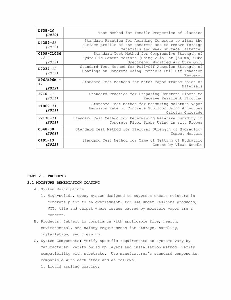
D638-10 (2010) Test Method for Tensile Properties of Plastics
D4259-88 (2012)
Standard Practice for Abrading Concrete to alter the surface profile of the concrete and to remove foreign
materials and weak surface laitance. C109/C109M-12 (2012)
Standard Test Method for Compressive Strength of Hydraulic Cement Mortars (Using 2-in. or [50-mm] Cube
Specimens) Modified Air Cure Only
D7234-12 (2012)
Standard Test Method for Pull-Off Adhesion Strength of Coatings on Concrete Using Portable Pull-Off Adhesion
Testers. E96/E96M -12 (2012)
Standard Test Methods for Water Vapor Transmission of Materials
F710-11 (2011)
Standard Practice for Preparing Concrete Floors to Receive Resilient Flooring
F1869-11 (2011)
Standard Test Method for Measuring Moisture Vapor Emission Rate of Concrete Subfloor Using Anhydrous
Calcium Chloride
F2170-11 (2011)
Standard Test Method for Determining Relative Humidity in Concrete Floor Slabs Using in situ Probes
C348-08 (2008)
Standard Test Method for Flexural Strength of Hydraulic-Cement Mortars
C191-13 (2013)
Standard Test Method for Time of Setting of Hydraulic Cement by Vicat Needle
PART 2 - PRODUCTS
2.1 MOISTURE REMEDIATION COATING
A. System Descriptions:
1. High-solids, epoxy system designed to suppress excess moisture in
concrete prior to an overlayment. For use under resinous products,
VCT, tile and carpet where issues caused by moisture vapor are a
concern.
B. Products: Subject to compliance with applicable fire, health,
environmental, and safety requirements for storage, handling,
installation, and clean up.
C. System Components: Verify specific requirements as systems vary by
manufacturer. Verify build up layers and installation method. Verify
compatibility with substrate. Use manufacturer’s standard components,
compatible with each other and as follows:
1. Liquid applied coating:

a. Resin: epoxy.
b. Formulation Description: Multiple component high solids.
c. Application: Per manufacturer’s written installation
requirements.
d. Thickness: minimum 10 mils
D. Material Vapor Permeance: Application shall achieve a permeance rating
of less than 0.1 perm in accordance with ASTM E96/E96M.
E. Maximum RH requirement: 100% testing in accordance with ASTM F2170.
2.2 CEMENTITIOUS SELF-LEVELING UNDERLAYMENT
A.
System Descriptions:
1. High performance self-leveling underlayment resurfacer. Single
component, self-leveling, cementitious material designed for easy
application as an underlayment for all types of flooring materials.
It is used for substrate repair and leveling.
B. Products: Subject to compliance with applicable fire, health,
environmental, and safety requirements for storage, handling,
installation, and clean up. Gypsum-based products are unacceptable.
C. System Characteristics:
1. Wearing Surface: smooth
2. Thickness: Per architectural drawings, ranging from feathered edge
to 1”, per application. Applications greater than 1” require
additional 3/8” aggregate to mix or as recommended by manufacturer.
D. Underlayment shall be calcium aluminate cement-based, containing
Portland cement. Gypsum-based products are unacceptable.
E. Compressive Strength: Minimum 4100 psi in 28 days in accordance with
ASTM C109/C109M.
Property Test Value
Tensile Strength
ASTM D638 4,400 psi
Volatile Organic Compound Limits (V.O.C.)
SCAMD Rule 1113 25 grams per liter
Permeance ASTM E96 0.1 perms
Tensile Modulus ASTM D638 1.9X10⁵ psi
Percent Elongation ASTM D638 12%
Cure Rate Per manufacture’s Data
4 hours Tack free with 24hr recoat window
Bond Strength ASTM D7234 100% bond to concrete failure

F. Flexural Strength: Minimum 1000 psi in 28 days in accordance with ASTM
C348
G. Dry Time: See manufacturer specifications.
H. Primer: compatible and as recommended by manufacturer for use over
intended substrate
I. System Components: Manufacturer's standard components that are
compatible with each other and as follows:
1. Primer:
a. Resin: copolymer
b. Formulation Description: single component ready to use.
c. Application Method: Squeegee and medium nap roller.
All puddles shall be removed, and material shall be allowed to
dry, 1-2 hours at 70F/21C.
d. Number of Coats: (1) one.
2. Grout Resurfacing Base:
a. Formulation Description: Single component, cementitious self-
leveling high-early and high-ultimate strength grout.
b. Application Method: colloidal mix pump, cam rake, spike roll.
1) Thickness of Coats: Per architectural scope, 1” lifts.
2) Number of Coats: More than one if needed.
c. Aggregates: for applications greater than 1inch, require
additional 3/8” aggregate to mix.
2.3
CEMENTITIOUS TROWEL-APPLIED UNDERLAYMENT(NOT SUITABLE FOR RESINOUS FLOOR FINISHES)
A. Underlayment shall be calcium aluminate cement-based, containing
Portland cement. Gypsum-based products are unacceptable.
B. Compressive Strength: Minimum 4000 psi in 28 days
C. Trowel-applied underlayment shall not contain silica quartz (sand).
D. Dry Time: Underlayment shall receive the application of floor covering
in 15-20 minutes.
Property Test Value
Compressive Strength
ASTM C109/C109M 2,200 psi @ 24 hrs 3,000 psi @ 7 days
Initial set time Final Set time
ASTM C191 30-45 min. 1 to 1.5 hours
Bond Strength ASTM D7234 100% bond to concrete failure
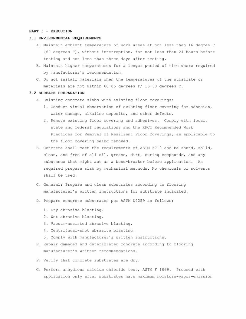
PART 3 - EXECUTION
3.1 ENVIRONMENTAL REQUIREMENTS
A. Maintain ambient temperature of work areas at not less than 16 degree C
(60 degrees F), without interruption, for not less than 24 hours before
testing and not less than three days after testing.
B. Maintain higher temperatures for a longer period of time where required
by manufacturer's recommendation.
C. Do not install materials when the temperatures of the substrate or
materials are not within 60-85 degrees F/ 16-30 degrees C.
3.2 SURFACE PREPARATION
A. Existing concrete slabs with existing floor coverings:
1. Conduct visual observation of existing floor covering for adhesion,
water damage, alkaline deposits, and other defects.
2. Remove existing floor covering and adhesives. Comply with local,
state and federal regulations and the RFCI Recommended Work
Practices for Removal of Resilient Floor Coverings, as applicable to
the floor covering being removed.
B. Concrete shall meet the requirements of ASTM F710 and be sound, solid,
clean, and free of all oil, grease, dirt, curing compounds, and any
substance that might act as a bond-breaker before application. As
required prepare slab by mechanical methods. No chemicals or solvents
shall be used.
C. General: Prepare and clean substrates according to flooring
manufacturer's written instructions for substrate indicated.
D. Prepare concrete substrates per ASTM D4259 as follows:
1. Dry abrasive blasting.
2. Wet abrasive blasting.
3. Vacuum-assisted abrasive blasting.
4. Centrifugal-shot abrasive blasting.
5. Comply with manufacturer's written instructions.
E. Repair damaged and deteriorated concrete according to flooring
manufacturer's written recommendations.
F. Verify that concrete substrates are dry.
G. Perform anhydrous calcium chloride test, ASTM F 1869. Proceed with
application only after substrates have maximum moisture-vapor-emission

rate of per flooring manufactures formal and project specific written
recommendation.
H. Perform in situ probe test, ASTM F2170. Proceed with application only
after substrates do not exceed a maximum potential equilibrium relative
humidity per flooring manufacture’s formal and project specific written
recommendation.
I. Provide a written report showing test placement and results.
J. Prepare joints in accordance with material manufacturer’s instructions.
K. Alkalinity: Measure surface pH in accordance with procedures provided
in ASTM F710 or as outlined by qualified testing agency or flooring
manufacturer’s technical representative.
L. Tolerances: Subsurface shall meet the flatness and levelness tolerance
specified on drawings or recommended by the floor finish manufacturer.
Tolerance shall also not to exceed 1/4” deviation in 10’. As required,
install underlayment to achieve required tolerance.
M. Other Subsurface: For all other subsurface conditions, such as wood or
metal, contact the floor finish or underlayment manufacturer, as
appropriate, for proper preparation practices.
3.3 MOISTURE REMEDIATION COATING:
A. Where results of relative humidity testing (ASTM F2170) exceed the
requirements of the specified flooring manufacturer, apply remedial
coating as specified to correct excessive moisture condition.
B. Prior to remedial floor coating installation mechanically prepare the
concrete surface to provide a concrete surface profile in accordance
with ASTM D4259.
C. Mix and apply moisture remediation coating in accordance with
manufacturer’s instructions.
3.4 CEMENTITOUS UNDERLAYMENT:
A. Install cementitious self-leveling underlayment as required to correct
surface defects, floor flatness or levelness corrections to meet the
tolerance requirements as or detailed on drawings, address non-moving
cracks or joints, provide a smooth surface for the installation of
floor covering, or meet elevation requirements detailed on drawings.
B. Mix and apply in accordance with manufacturer's instructions.

3.5 PROTECTION
A. Prior to the installation of the finish flooring, the surface of the
underlayment should be protected from abuse by other trades by the use
of plywood, tempered hardwood, or other suitable protection course
3.6 FIELD QUALITY CONTROL
A. Where specified, field sampling of products shall be conducted by a
qualified, independent testing facility.
- - - E N D - - -

SECTION 09 06 00 SCHEDULE FOR FINISHES
PART 1 – GENERAL
1.1 DESCRIPTION
This section contains a coordinated system in which requirements for
materials specified in other sections shown are identified by
abbreviated material names and finish codes in the room finish schedule
or shown for other locations.
1.2 MANUFACTURERS
Manufacturer’s trade names and numbers used herein are only to identify
colors, finishes, textures and patterns. Products of other
manufacturer’s equivalent to colors, finishes, textures and patterns of
manufacturers listed that meet requirements of technical specifications
will be acceptable upon approval in writing by contracting officer for
finish requirements.
1.3 SUBMITALS
Submit in accordance with SECTION 01 33 23, SHOP DRAWINGS, PRODUCT
DATA, AND SAMPLES provide quadruplicate samples for color approval of
materials and finishes specified in this section.
1.4 APPLICABLE PUBLICATIONS
A. Publications listed below form a part of this specification to the
extent referenced. Publications are referenced in text by basic
designation only.
B. MASTER PAINTING INSTITUTE: (MPI)
2001....................Architectural Painting Specification Manual
PART 2 – PRODUCTS

OMAHA FINISH SCHEDULE
2.8 DIVISION 08 - OPENINGS
A. SECTION 08 14 00, WOOD DOORS
Component Material Finish/Color
Doors White Birch or White Maple
(Match Existing)
CC-1 / LEVEL 4
Frames HM PT-3 / ALKYD ENAMEL
B. WINDOW STOOLS
Finish Code Material Manufacturer Finish
SS-1 QUARTZ Zodiac Smokey Topaz
2.9 DIVISION 09 - FINISHES
A. SECTION 09 30 13, CERAMIC TILE
1. SECTION 09 30 13, CERAMIC TILE (CT)
Finish Code Size Shape Pattern Manufacturer Mfg. Color Name/No.
CT-1, Floor 300 MM X 300 MM (12” X 12”)
Square Straight Florida Tile Urbanite, Stone FTI2382112x12
CT-2, Walls 300 MM X 300 MM (12” X 12”)
Square Straight Florida Tile Urbanite, Gild, FTI2383512x12
CT-3, Accent Strip, 12”
300 MM X 300 MM (12” X 12”)
Square mosaic (2” x 2” mesh
mount)
Straight Florida Tile Urbanite, Gild FTI23835M128
CT-4, Match CT-2 in color
3”x24” Bullnose Straight Florida Tile Urbanite, P43N9
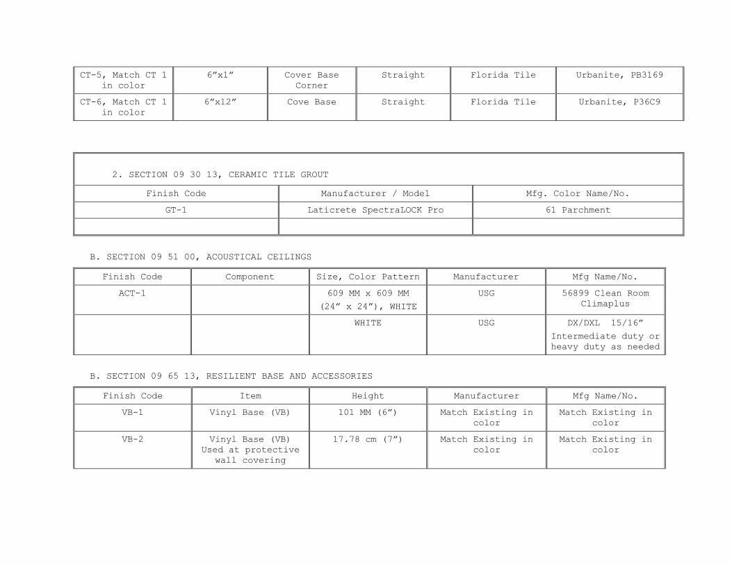
CT-5, Match CT 1 in color
6”x1” Cover Base Corner
Straight Florida Tile Urbanite, PB3169
CT-6, Match CT 1 in color
6”x12” Cove Base Straight Florida Tile Urbanite, P36C9
2. SECTION 09 30 13, CERAMIC TILE GROUT
Finish Code Manufacturer / Model Mfg. Color Name/No.
GT-1 Laticrete SpectraLOCK Pro 61 Parchment
B. SECTION 09 51 00, ACOUSTICAL CEILINGS
Finish Code Component Size, Color Pattern Manufacturer Mfg Name/No.
ACT-1 609 MM x 609 MM
(24” x 24”), WHITE
USG 56899 Clean Room Climaplus
WHITE USG DX/DXL 15/16”
Intermediate duty or heavy duty as needed
B. SECTION 09 65 13, RESILIENT BASE AND ACCESSORIES
Finish Code Item Height Manufacturer Mfg Name/No.
VB-1 Vinyl Base (VB) 101 MM (6”) Match Existing in color
Match Existing in color
VB-2 Vinyl Base (VB) Used at protective
wall covering
17.78 cm (7”) Match Existing in color
Match Existing in color

C. SECTION 09 65 16, RESILIENT SHEET FLOORING
Finish Code Item Manufacturer Product .
RSF-1 Heat Welded Resilient Sheet
Flooring
Mannington Realities, Maple Grove, Maple 5621
WR-1 Heat Welding Rod Mannington Match Maple floor
D. SECTION 09 65-19, RESILIENT TILE FLOORING
Finish Code Item Manufacturer Product
VPTF-1 3” X 36” PLANK MANNINGTON, AMTICO (REPRESENTATIVE, TODD MITHELMAN (515) 331-6665
WOOD: VINTAGE TEAK AROW7600
VPTF-2 3” X 36” PLANK MANNINGTON, AMTICO (REPRESENTATIVE, TODD MITHELMAN (515) 331-6665
WOOD, MAPLE AROW6840
E.SECTION 09 68 00, CARPET MODULES (CPT)
Finish Code Item Manufacturer Product name
CPT-1 24”X24” (60.9 cm x 60.9 cm)
LEES, SERENITY, TRANSFORMATIVE,
GT324

F. SECTION 09 91 00, PAINT AND COATINGS
G.
1. MPI Gloss and Sheen Standards Gloss @60 Sheen @85
Gloss Level 1 a traditional matte finish-flat max 5 units, and max 10 units
Gloss Level 2 a high side sheen flat-“a velvet-like” max 10 units, and 10-35 units
finish
Gloss Level 3 a traditional “egg-shell like” finish 10-25 units, and 10-35 units
Gloss Level 4 a “satin-like” finish 20-35 units, and min. 35 units
Gloss Level 5 a traditional semi-gloss 35-70 units
Gloss Level 6 a traditional gloss 70-85 units
Gloss level 7 a high gloss more than 85 units
1. Paint code Gloss Manufacturer Mfg. Color Name/No.
EPT-1 Level 7 Sherwin Williams Epoxy – Nomadic Desert SW6017
EPT-2 Level 7 Glidden Epoxy – Hiding Room 2013
PT-3 Level 5 --- Match existing door frames
PT-4 Match Existing Match existing wall color
2. Stain Code (S) Gloss and Transparency Manufacturer Mfg. Color Name/No.
ST-1 Level 4 Sherwin Williams CC
3. Clear coatings Code(CC) Gloss Manufacturer Mfg. Color Name/No.
CC-1 Level 4 Sherwin Williams --
2.10 DIVISION 10 - SPECIALTIES
A. SECTION 10 21 13, TOILET COMPARTMENTS
FINISH CODE MATERIAL MANUFACTURER COLOR
TC-1 Solid Phenolic Columbia 7738 Cognac Maple

B. SECTION 10 26 00, WALL AND DOOR PROTECTION
FINISH CODE MATERIAL MANUFACTURER COLOR
HR-1 Rigid Plastic Match Existing Match Existing
WP-1 Rigid Plastic Acrovyn 102 Desert Sand
2.10 DIVISION 12 - FURNISHINGS
A. CABINETRY.
FINISH CODE MATERIAL MANUFACTURER COLOR
SS-1 Solid Surface Cabinetry Tops and transaction work surfaces
Zodiaq Smokey Topaz
PL-1 Plastic Laminate - 1 Formica Amber Maple
PL-2 Plastic Laminate - 2 Formica Natural Teak


PART III EXECUTION
3.1 FINISH SCHEDULES & MISCELLANEOUS ABBREVIATIONS
FINISH SCHEDULE & MISCELLANEOUS ABBREVIATIONS Term Abbreviation Acoustical Ceiling ACT Carpet Module Tile CPT Ceramic Tile CT Clear Coat CC Concrete CONC Corner Guard CG Epoxy Coating EC Existing EX Exterior EXT Grout GT Gypsum Wallboard GWB Hand Rail HR High Glazed Coating SC Hollow Metal HM Material MAT Mortar M Natural Finish NF Paint PT Plaster PLAS Plastic Laminate PL Solid Surface Material SS Stain ST Transition Strip TS Vinyl Base VB Vinyl Sheet Flooring (Welded Seams)
WSF
Vinyl Sheet Flooring (Welded Seams)
WSFB
Wall Protection WP Wood WD

3.2 FINISH SCHEDULE SYMBOLS
Symbol Definition ** Same finish as adjoining walls - No color required EX Existing XX To match existing EFTR Existing finish to remain RM Remove 3.3 ROOM FINISH SCHEDULE
A. Match adjoining or existing similar surfaces colors, textures or patterns where disturbed or damaged
by alterations or new work when not scheduled.
B. ROOM FINISH SCHEDULE:
1. See drawings for Room Finish Schedule.
- - - END OF SECTION 09 06 00 - - -

SECTION 09 22 16 NON-STRUCTURAL METAL FRAMING
PART 1 - GENERAL
1.1 DESCRIPTION
This section specifies steel studs wall systems, shaft wall systems,
ceiling or soffit suspended or furred framing, wall furring, fasteners,
and accessories for the screw attachment of gypsum board, plaster bases
or other building boards.
1.2 RELATED WORK
A. Ceiling suspension systems for acoustical tile or panels and lay in
gypsum board panels: Section 09 51 00, ACOUSTICAL CEILINGS, Section 09
29 00, GYPSUM BOARD.
1.3 TERMINOLOGY
A. Description of terms shall be in accordance with ASTM C754, ASTM C11,
ASTM C841 and as specified.
B. Underside of Structure Overhead: In spaces where steel trusses or bar
joists are shown, the underside of structure overhead shall be the
underside of the floor or roof construction supported by beams,
trusses, or bar joists. In interstitial spaces with walk-on floors the
underside of the walk-on floor is the underside of structure overhead.
C. Thickness of steel specified is the minimum bare (uncoated) steel
thickness.
1.4 SUBMITTALS
A. Submit in accordance with Section 01 33 23, SHOP DRAWINGS, PRODUCT
DATA, AND SAMPLES.
B. Manufacturer's Literature and Data:
1. Studs, runners and accessories.
2. Hanger inserts.
3. Channels (Rolled steel).
4. Furring channels.
5. Screws, clips and other fasteners.
C. Shop Drawings:
1. Typical ceiling suspension system.
2. Typical metal stud and furring construction system including details
around openings and corner details.
D. Test Results: Fire rating test designation, each fire rating required
for each assembly.

1.5 DELIVERY, IDENTIFICATION, HANDLING AND STORAGE
In accordance with the requirements of ASTM C754.
1.6 APPLICABLE PUBLICATIONS
A. The publications listed below form a part of this specification to the
extent referenced. The publications are referenced in the text by the
basic designation only.
B. American Society For Testing And Materials (ASTM)
A123-09.................Zinc (Hot-dip Galvanized) Coatings on Iron and
Steel Products
A653/A653M-09...........Steel Sheet, Zinc-Coated (Galvanized) or Zinc-
Iron Alloy Coated (Galvannealed) by the Hot-Dip
Process
A641-09.................Zinc-Coated (Galvanized) Carbon Steel Wire
C11-10..................Terminology Relating to Gypsum and Related
Building Materials and Systems
C635-07.................Manufacture, Performance, and Testing of Metal
Suspension System for Acoustical Tile and
Lay-in Panel Ceilings
C636-06.................Installation of Metal Ceiling Suspension
Systems for Acoustical Tile and Lay-in Panels
C645-09.................Non-Structural Steel Framing Members
C754-09.................Installation of Steel Framing Members to
Receive Screw-Attached Gypsum Panel Products
C841-03(R2008)..........Installation of Interior Lathing and Furring
C954-07.................Steel Drill Screws for the Application of
Gypsum Panel Products or Metal Plaster Bases to
Steel Studs from 0.033 in. (0.84 mm) to 0.112
in. (2.84 mm) in Thickness
C1002-07................Steel Self-Piercing Tapping Screws for the
Application of Gypsum Panel Products or Metal
Plaster Bases to Wood Studs or Steel Studs
E580-09.................Application of Ceiling Suspension Systems for
Acoustical Tile and Lay-in Panels in Areas
Requiring Moderate Seismic Restraint.
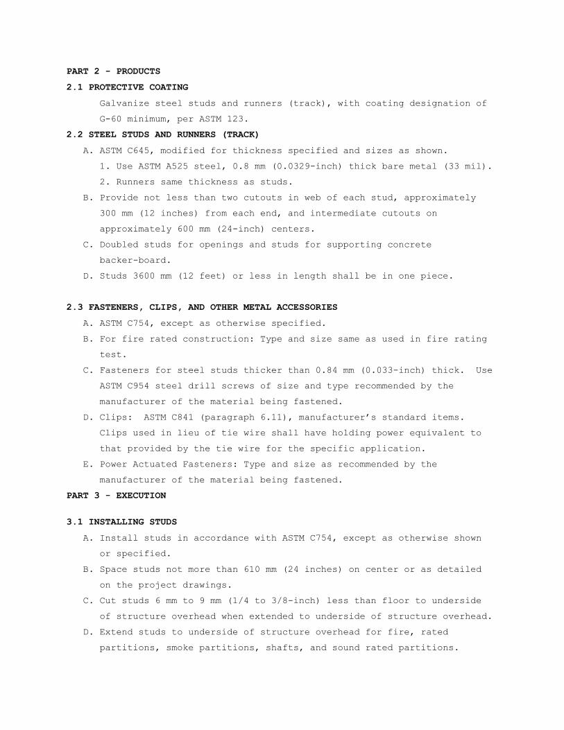
PART 2 - PRODUCTS
2.1 PROTECTIVE COATING
Galvanize steel studs and runners (track), with coating designation of
G-60 minimum, per ASTM 123.
2.2 STEEL STUDS AND RUNNERS (TRACK)
A. ASTM C645, modified for thickness specified and sizes as shown.
1. Use ASTM A525 steel, 0.8 mm (0.0329-inch) thick bare metal (33 mil).
2. Runners same thickness as studs.
B. Provide not less than two cutouts in web of each stud, approximately
300 mm (12 inches) from each end, and intermediate cutouts on
approximately 600 mm (24-inch) centers.
C. Doubled studs for openings and studs for supporting concrete
backer-board.
D. Studs 3600 mm (12 feet) or less in length shall be in one piece.
2.3 FASTENERS, CLIPS, AND OTHER METAL ACCESSORIES
A. ASTM C754, except as otherwise specified.
B. For fire rated construction: Type and size same as used in fire rating
test.
C. Fasteners for steel studs thicker than 0.84 mm (0.033-inch) thick. Use
ASTM C954 steel drill screws of size and type recommended by the
manufacturer of the material being fastened.
D. Clips: ASTM C841 (paragraph 6.11), manufacturer’s standard items.
Clips used in lieu of tie wire shall have holding power equivalent to
that provided by the tie wire for the specific application.
E. Power Actuated Fasteners: Type and size as recommended by the
manufacturer of the material being fastened.
PART 3 - EXECUTION
3.1 INSTALLING STUDS
A. Install studs in accordance with ASTM C754, except as otherwise shown
or specified.
B. Space studs not more than 610 mm (24 inches) on center or as detailed
on the project drawings.
C. Cut studs 6 mm to 9 mm (1/4 to 3/8-inch) less than floor to underside
of structure overhead when extended to underside of structure overhead.
D. Extend studs to underside of structure overhead for fire, rated
partitions, smoke partitions, shafts, and sound rated partitions.

E. Openings:
1. Frame jambs of openings in stud partitions and furring with two
studs placed back to back or as shown.
2. Fasten back to back studs together with 9 mm (3/8-inch) long Type S
pan head screws at not less than 600 mm (two feet) on center,
staggered along webs.
3. Studs fastened flange to flange shall have splice plates on both
sides approximately 50 X 75 mm (2 by 3 inches) screwed to each stud
with two screws in each stud. Locate splice plates at 600 mm (24
inches) on center between runner tracks.
F. Fastening Studs:
1. Fasten studs located adjacent to partition intersections, corners
and studs at jambs of openings to flange of runner tracks with two
screws through each end of each stud and flange of runner.
2. Do not fasten studs to top runner track when studs extend to
underside of structure overhead.
G. Chase Wall Partitions:
1. Locate cross braces for chase wall partitions to permit the
installation of pipes, conduits, carriers and similar items.
2. Use studs or runners as cross bracing not less than 63 mm (2-1/2
inches wide).
H. Form control joint, with double studs spaced 13 mm (1/2-inch) apart.
3.3 INSTALLING WALL FURRING FOR FINISH APPLIED TO ONE SIDE ONLY
A. In accordance with ASTM C754, or ASTM C841 except as otherwise
specified or shown.
B. Wall furring-Stud System:
1. Framed with 63 mm (2-1/2 inch) or narrower studs, 600 mm (24 inches)
on center.
2. Brace as specified in ASTM C754 for Wall Furring-Stud System or
brace with sections or runners or studs placed horizontally at not
less than three foot vertical intervals on side without finish.
3. Securely fasten braces to each stud with two Type S pan head screws
at each bearing.
C. Installing Wall Furring-Bracket System: Space furring channels not more
than 400 mm (16 inches) on center.
3.4 INSTALLING SUPPORTS REQUIRED BY OTHER TRADES
A. Provide for attachment and support of electrical outlets, plumbing,
laboratory or heating fixtures, recessed type plumbing fixture
accessories, access panel frames, wall bumpers, wood seats, toilet
stall partitions, dressing booth partitions, urinal screens,
chalkboards, tackboards, wall-hung casework, handrail brackets,
recessed fire extinguisher cabinets and other items like auto door
buttons and auto door operators supported by stud construction.
B. Provide additional studs where required. Install metal backing plates,
or special metal shapes as required, securely fastened to metal studs.
3.5 INSTALLING FURRED AND SUSPENDED CEILINGS OR SOFFITS
A. Install furred and suspended ceilings or soffits in accordance with
ASTM C754 or ASTM C841 except as otherwise specified or shown for screw
attached gypsum board ceilings and for plaster ceilings or soffits.
1. Space framing at 400 mm (16-inch) centers for metal lath anchorage.
2. Space framing at 600 mm (24-inch) centers for gypsum board
anchorage.
B. Existing concrete construction exposed or concrete on steel decking:
1. Use power actuated fasteners either eye pin, threaded studs or drive
pins for type of hanger attachment required.
2. Install fasteners at approximate mid height of concrete beams or
joists. Do not install in bottom of beams or joists.
3.6 TOLERANCES
A. Fastening surface for application of subsequent materials shall not
vary more than 3 mm (1/8-inch) from the layout line.
B. Plumb and align vertical members within 3 mm (1/8-inch.)
C. Level or align ceilings within 3 mm (1/8-inch.)
- - - END OF SECTION 09 22 16 - - -

SECTION 09 29 00 GYPSUM BOARD
PART 1 - GENERAL
1.1 DESCRIPTION
This section specifies installation and finishing of gypsum board.
1.2 RELATED WORK
A. Installation of steel framing members for walls, partitions, furring,
soffits, and ceilings: Section 09 22 16, NON-STRUCTURAL METAL FRAMING.
B. Acoustical Sealants: Section 07 92 00, JOINT SEALANTS.
1.3 TERMINOLOGY
A. Definitions and description of terms shall be in accordance with ASTM
C11, C840, and as specified.
B. Underside of Structure Overhead: In spaces where steel trusses or bar
joists are shown, the underside of structure overhead shall be the
underside of the floor or roof construction supported by the trusses or
bar joists.
C. "Yoked": Gypsum board cut out for opening with no joint at the opening
(along door jamb or above the door).
1.4 SUBMITTALS
A. Submit in accordance with Section 01 33 23, SHOP DRAWINGS, PRODUCT
DATA, AND SAMPLES.
B. Manufacturer's Literature and Data:
1. Cornerbead and edge trim.
2. Finishing materials.
3. Gypsum board, each type.
C. Shop Drawings:
1. Typical gypsum board installation, showing corner details, edge trim
details and the like.
2. Typical sound rated assembly, showing treatment at perimeter of
partitions and penetrations at gypsum board.
D. Samples:
1. Cornerbead.
2. Edge trim.
3. Control joints.
E. Test Results:
1. Sound rating test.

1.5 DELIVERY, IDENTIFICATION, HANDLING AND STORAGE
In accordance with the requirements of ASTM C840.
1.6 ENVIRONMENTAL CONDITIONS
In accordance with the requirements of ASTM C840.
1.7 APPLICABLE PUBLICATIONS
A. The publications listed below form a part of this specification to the
extent referenced. The publications are referenced in the text by the
basic designation only.
B. American Society for Testing And Materials (ASTM):
C11-08..................Terminology Relating to Gypsum and Related
Building Materials and Systems
C475-02.................Joint Compound and Joint Tape for Finishing
Gypsum Board
C840-08.................Application and Finishing of Gypsum Board
C919-08.................Sealants in Acoustical Applications
C954-07.................Steel Drill Screws for the Application of
Gypsum Board or Metal Plaster Bases to Steel
Stud from 0.033 in. (0.84mm) to 0.112 in.
(2.84mm) in thickness
C1002-07................Steel Self-Piercing Tapping Screws for the
Application of Gypsum Panel Products or Metal
Plaster Bases to Wood Studs or Steel Studs
C1047-05................Accessories for Gypsum Wallboard and Gypsum
Veneer Base
C1177-06................Glass Mat Gypsum Substrate for Use as Sheathing
C1658-06................Glass Mat Gypsum Panels
C1396-06................Gypsum Board
E84-08..................Surface Burning Characteristics of Building
Materials
C. Underwriters Laboratories Inc. (UL):
Latest Edition..........Fire Resistance Directory
D. Inchcape Testing Services (ITS):
Latest Editions.........Certification Listings
PART 2 - PRODUCTS
2.1 GYPSUM BOARD
A. Gypsum Board: ASTM C1396, Type X, 16 mm (5/8 inch) thick unless shown
otherwise. Shall contain a minimum of 20 percent recycled gypsum.
B. Water Resistant Gypsum Backing Board: ASTM C620, Type X, 16 mm (5/8
inch) thick.
C. Gypsum cores shall contain a minimum of 95 percent post industrial
recycled gypsum content. Paper facings shall contain 100 percent post-
consumer recycled paper content.
2.2 ACCESSORIES
A. ASTM C1047, except form of 0.39 mm (0.015 inch) thick zinc coated steel
sheet or rigid PVC plastic.
B. Flanges not less than 22 mm (7/8 inch) wide with punchouts or
deformations as required to provide compound bond.
2.3 FASTENERS
A. ASTM C1002 and ASTM C840, except as otherwise specified.
B. ASTM C954, for steel studs thicker than 0.04 mm (0.33 inch).
C. Select screws of size and type recommended by the manufacturer of the
material being fastened.
D. Clips: Zinc-coated (galvanized) steel; gypsum board manufacturer's
standard items.
2.4 FINISHING MATERIALS AND LAMINATING ADHESIVE
ASTM C475 and ASTM C840. Free of antifreeze, vinyl adhesives,
preservatives, biocides and other VOC. Adhesive shall contain a maximum
VOC content of 50 g/l.
PART 3 - EXECUTION
3.1 GYPSUM BOARD HEIGHTS
A. Extend all layers of gypsum board from floor to underside of structure
overhead on following partitions and furring:
1. Two sides of partitions:
a. Smoke partitions.
b. Sound rated partitions.
c. Full height partitions shown.
d. Corridor partitions.
2. One side of partitions or furring:
a. Inside of exterior wall furring or stud construction.
b. Room side of room with suspended ceilings.
B. In locations other than those specified, extend gypsum board from floor
to heights as follows:
1. Not less than 100 mm (4 inches) above suspended acoustical ceilings.
2. At ceiling of suspended gypsum board ceilings.

3. At existing ceilings.
3.2 INSTALLING GYPSUM BOARD
A. Coordinate installation of gypsum board with other trades and related
work.
B. Install gypsum board in accordance with ASTM C840, except as otherwise
specified.
C. Backing Board for Wet Areas: NOT USED
D. Use gypsum boards in maximum practical lengths to minimize number of
end joints.
E. Bring gypsum board into contact, but do not force into place.
F. Walls (Except Shaft Walls):
1. When gypsum board is installed parallel to framing members, space
fasteners 300 mm (12 inches) on center in field of the board, and
200 mm (8 inches) on center along edges.
2. When gypsum board is installed perpendicular to framing members,
space fasteners 300 mm (12 inches) on center in field and along
edges.
3. Stagger screws on abutting edges or ends.
4. For single-ply construction, apply gypsum board with long dimension
either parallel or perpendicular to framing members as required to
minimize number of joints except gypsum board shall be applied
vertically over "Z" furring channels.
5. Control Joints ASTM C840 and as follows:
a. Locate at both side jambs of openings if gypsum board is not
"yoked". Use one system throughout.
b. Not required for wall lengths less than 9000 mm (30 feet).
c. Extend control joints the full height of the wall or length of
soffit/ceiling membrane.
G. Acoustical or Sound Rated Partitions, Fire and Smoke Partitions:
1. Cut gypsum board for a space approximately 3 mm to 6 mm (1/8 to 1/4
inch) wide around partition perimeter.
2. Coordinate for application of caulking or sealants to space prior to
taping and finishing.
H. Electrical and Telecommunications Boxes:
1. Seal annular spaces between electrical and telecommunications
receptacle boxes and gypsum board partitions.
I. Accessories:
1. Set accessories plumb, level and true to line, neatly mitered at
corners and intersections, and securely attach to supporting
surfaces as specified.
2. Install in one piece, without the limits of the longest commercially
available lengths.
3. Corner Beads:
a. Install at all vertical and horizontal external corners and where
shown.
b. Use screws only. Do not use crimping tool.
4. Edge Trim (casings Beads):
a. At both sides of expansion and control joints unless shown
otherwise.
b. Where gypsum board terminates against dissimilar materials and at
perimeter of openings, except where covered by flanges, casings
or permanently built-in equipment.
c. Where gypsum board surfaces of non-load bearing assemblies abut
load bearing members.
d. Where shown.
3.3 INSTALLING GYPSUM SHEATHING
A. Install in accordance with ASTM C840, except as otherwise specified or
shown.
B. Use screws of sufficient length to secure sheathing to framing.
C. Space screws 9 mm (3/8 inch) from ends and edges of sheathing and 200
mm (8 inches) on center. Space screws a maximum of 200 mm (8 inches) on
center on intermediate framing members.
D. Apply 600 mm by 2400 mm (2 foot by 8 foot) sheathing boards
horizontally with tongue edge up.
E. Apply 1200 mm by 2400 mm or 2700 mm (4 ft. by 8 ft. or 9 foot) gypsum
sheathing boards vertically with edges over framing.
3.4 FINISHING OF GYPSUM BOARD
A. Finish joints, edges, corners, and fastener heads in accordance with
ASTM C840. Use Level 5 finish for all finished areas open to public
view.
B. Before proceeding with installation of finishing materials, assure the
following:
1. Gypsum board is fastened and held close to framing or furring.
2. Fastening heads in gypsum board are slightly below surface in dimple
formed by driving tool.

C. Finish joints, fasteners, and all openings, including openings around
penetrations, on that part of the gypsum board extending above
suspended ceilings to seal surface of non decorated smoke barrier,
sound rated gypsum board construction. After the installation of
hanger rods, hanger wires, supports, equipment, conduits, piping and
similar work, seal remaining openings and maintain the integrity of the
smoke barrier, fire rated and sound rated construction. Sanding is not
required of non decorated surfaces.
3.5 REPAIRS
A. After taping and finishing has been completed, and before decoration,
repair all damaged and defective work, including nondecorated surfaces.
B. Patch holes or openings 13 mm (1/2 inch) or less in diameter, or
equivalent size, with a setting type finishing compound or patching
plaster.
C. Repair holes or openings over 13 mm (1/2 inch) diameter, or equivalent
size, with 16 mm (5/8 inch) thick gypsum board secured in such a manner
as to provide solid substrate equivalent to undamaged surface.
D. Tape and refinish scratched, abraded or damaged finish surfaces
including cracks and joints in non decorated surface to provide smoke
tight construction and fire protection equivalent.
- - - END OF SECTION 09 29 00 - - -

SECTION 09 30 13 CERAMIC/PORCELAIN TILING
PART 1 - GENERAL
1.1 DESCRIPTION
This section specifies ceramic, porcelain tile, waterproofing membranes
for thin-set applications, crack isolation membranes, tile backer board
and terrazzo shower receptors.
1.2 RELATED WORK
A. Color, texture and pattern of field tile and trim shapes, size of field
tile, trim shapes, and color of grout specified: Section 09 06 00,
SCHEDULE FOR FINISHES.
1.3 SUBMITTALS
A. Submit in accordance with Section 01 33 23, SHOP DRAWINGS, PRODUCT
DATA, AND SAMPLES.
B. Samples:
1. Base tile, each type, each color, each size.
2. Porcelain tile, each type, color, patterns and size.
3. Wall (or wainscot) tile, each color, size and pattern.
4. Trim shapes, bullnose cap and cove including bullnose cap and base
pieces at internal and external corners of vertical surfaces, each
type, color, and size.
C. Product Data:
1. Ceramic and porcelain tile, marked to show each type, size, and
shape required.
2. Cementitious backer unit.
3. Dry-set Portland cement mortar and grout.
4. Reinforcing tape.
5. Leveling compound.
6. Latex-Portland cement mortar and grout.
7. Commercial Portland cement grout.
8. Organic adhesive.
9. Slip resistant tile.
10. Waterproofing isolation membrane.
11. Terrazzo shower receptor
12. Fasteners.

D. Certification:
1. Master grade, ANSI A137.1.
2. Manufacturer's certificates indicating that the following materials
comply with specification requirements:
a. Commercial Portland cement grout.
b. Cementitious backer unit.
c. Dry-set Portland cement mortar and grout.
d. Reinforcing tape.
e. Latex-Portland cement mortar and grout.
f. Leveling compound.
g. Organic adhesive.
h. Waterproof isolation membrane.
1.4 DELIVERY AND STORAGE
A. Deliver materials in containers with labels legible and intact and
grade-seals unbroken.
B. Store material to prevent damage or contamination.
1.5 APPLICABLE PUBLICATIONS
A. Publications listed below form a part of this specification to the
extent referenced. Publications are referenced in text by basic
designation only.
B. American National Standards Institute (ANSI):
A10.20-05...............Safety Requirements for Ceramic Tile, Terrazzo,
and Marble Works
A108.1A-05..............Installation of Ceramic Tile in the Wet-Set
Method with Portland Cement Mortar
A108.1B-05..............Installation of Ceramic Tile on a Cured
Portland Cement Mortar Setting Bed with dry-Set
or latex-Portland Cement Mortar
A108.1C-05..............Contractors Option; Installation of Ceramic
Tile in the Wet-Set method with Portland Cement
Mortar or Installation of Ceramic Tile on a
Cured Portland Cement Mortar Setting Bed with
Dry-Set or Latex-Portland Cement Mortar
A108.4-05...............Installation of Ceramic Tile with Organic
Adhesives or Water Cleanable Tile Setting Epoxy
Adhesives

A108.5-05...............Installation of Ceramic Tile with Dry-Set
Portland Cement Mortar or Latex-Portland Cement
Mortar
A108.6-05...............Installation of Ceramic Tile with Chemical
Resistant, Water Cleanable Tile-Setting and
Grouting Epoxy
A108.8-05...............Installation of Ceramic Tile with Chemical
Resistant Furan Resin Mortar and Grout
A108.10-05..............Installation of Grout in Tilework
A108.11-05..............Interior Installation of Cementitious Backer
Units
A108.13-05..............Installation of Load Bearing, Bonded,
Waterproof Membranes for Thin-Set Ceramic Tile
and Dimension Stone
A118.1-05...............Dry-Set Portland Cement Mortar
A118.4-05...............Latex-Portland Cement Mortar
A118.6-05...............Standard Cement Grouts for Tile Installation
A118.9-05...............Cementitious Backer Units
A118.10-05..............Load Bearing, Bonded, Waterproof Membranes for
Thin-Set Ceramic Tile and Dimension Stone
Installation
A136.1-05...............Organic Adhesives for Installation of Ceramic
Tile
A137.1-88...............Ceramic Tile
C. American Society For Testing And Materials (ASTM):
A185-07.................Steel Welded Wire Fabric, Plain, for Concrete
Reinforcing
C109/C109M-07...........Standard Test Method for Compressive Strength
of Hydraulic Cement Mortars (Using 2 inch. or
[50-mm] Cube Specimens)
C241-90 (R2005).........Abrasion Resistance of Stone Subjected to Foot
Traffic
C348-02.................Standard Test Method for Flexural Strength of
Hydraulic-Cement Mortars
C627-93(R2007)..........Evaluating Ceramic Floor Tile Installation
Systems Using the Robinson-Type Floor Tester
C954-07.................Steel Drill Screws for the Application of
Gypsum Board on Metal Plaster Base to Steel
Studs from 0.033 in (0.84 mm) to 0.112 in (2.84
mm) in thickness
C979-05.................Pigments for Integrally Colored Concrete
C1002-07................Steel Self-Piercing Tapping Screws for the
Application of Panel Products
C1027-99(R2004).........Determining “Visible Abrasion Resistance on
Glazed Ceramic Tile”
C1028-07................Determining the Static Coefficient of Friction
of Ceramic Tile and Other Like Surfaces by the
Horizontal Dynamometer Pull Meter Method
C1178/C1178M-06.........Standard Specification for Coated Glass Mat
Water-Resistant Gypsum Backing Panel
D4397-02................Standard Specification for Polyethylene
Sheeting for Construction, Industrial and
Agricultural Applications
C. Tile Council of America, Inc. (TCA):
2007....................Handbook for Ceramic Tile Installation
PART 2 - PRODUCTS
2.1 TILE
A. Comply with ANSI A137.1, Standard Grade, except as modified:
1. Inspection procedures listed under the Appendix of ANSI A137.1.
2. Abrasion Resistance Classification:
a. Tested in accordance with values listed in Table 1, ASTM C 1027.
b. Class V, 12000 revolutions for floors in Corridors, Kitchens,
Storage including Refrigerated Rooms
c. Class IV, 6000 revolutions for remaining areas.
3. Slip Resistant Tile for Floors:
a. Coefficient of friction, when tested in accordance with ASTM
C1028, required for level of performance:
1) Not less than 0.7 (wet condition) for bathing areas.
2) Not less than 0.8 on ramps for wet and dry conditions.
3) Not less than 0.6, except 0.8 on ramps as stated above, for
wet and dry conditions for other areas.
in face at rate of approximately 7.5 percent of surface area.
4. Factory Blending: For tile with color variations, within the ranges
selected during sample submittals blend tile in the factory and

package so tile units taken from one package show the same range in
colors as those taken from other packages and match approved
samples.
B. Unglazed Ceramic Mosaic Tile: Nominal 6 mm (1/4 inch) thick with
cushion edges.
C. Glazed Wall Tile: Cushion edges, glazing, as specified in Section 09 06
00, SCHEDULE FOR FINISHES.
D. Porcelain Paver Tile: Nominal 8 mm (5/16 inch) thick, with cushion
edges. Porcelain tile produced by the dust pressed method shall be made
of approximately 50% feldspar; the remaining 50% shall be made up of
various high-quality light firing ball clays yielding a tile with a
water absorption rate of 0.5% or less and a breaking strength of
between 390 to 400 pounds.
E. Trim Shapes:
1. Conform to applicable requirements of adjoining floor and wall tile.
2. Use trim shapes sizes conforming to size of adjoining field wall
tile including existing spaces unless detailed or specified
otherwise in Section 09 06 00, SCHEDULE FOR FINISHES.
3. Internal and External Corners:
a. Square internal and external corner joints are not acceptable.
b. External corners including edges: Use bullnose shapes.
c. Internal corners: Use cove shapes.
d. Base to floor internal corners: Use special shapes providing
integral cove vertical and horizontal joint.
e. Base to floor external corners: Use special shapes providing
bullnose vertical edge with integral cove horizontal joint. Use
stop at bottom of openings having bullnose return to wall.
f. Wall top edge internal corners: Use special shapes providing
integral cove vertical joint with bullnose top edge.
g. Wall top edge external corners: Use special shapes providing
bullnose vertical and horizontal joint edge.
h. For unglazed ceramic mosaic and glazed wall tile installed in
Portland cement mortar setting bed, use cove and bullnose shapes
as applicable. When ceramic mosaic wall and base tile is
required, use C Series cove and bullnose shapes.
i. For unglazed ceramic mosaic and glazed wall tile installed in
dry-set Portland cement mortar, latex-Portland cement mortar, and

organic adhesive (thin set methods), use cove and surface
bullnose shapes as applicable.
j. Provide cove and bullnose shapes where shown, and required to
complete tile work.
2.2 CEMENTITIOUS BACKER UNITS
A. Use in showers or wet areas.
B. ANSI A118.9.
C. Use Cementitious backer units in maximum available lengths.
D. Backer unit meet or exceed the following additional physical
properties:
Property Test Method Value
Water absorption ASTM C948 Less than 20 percent by weight
2.3 JOINT MATERIALS FOR CEMENTITIOUS BACKER UNITS
A. Reinforcing Tape: Vinyl coated woven glass fiber mesh tape, open weave,
50 mm (2 inches) wide. Tape with pressure sensitive adhesive backing
will not be permitted.
B. Tape Embedding Material: Latex-Portland cement mortar complying with
ANSI A118.4.
C. Joint material, including reinforcing tape, and tape embedding
material, shall be as specifically recommended by the backer unit
manufacturer.
2.4 FASTENERS
A. Screws for Cementitious Backer Units.
1. Standard screws for gypsum board are not acceptable.
2. Minimum 11 mm (7/16 inch) diameter head, corrosion resistant coated,
with washers.
3. ASTM C954 for steel 1 mm (0.033 inch) thick.
4. ASTM C1002 for steel framing less than 0.0329 inch thick.
B. Washers: Galvanized steel, 13 mm (1/2 inch) minimum diameter.
2.5 GLASS MAT WATER RESISTANT GYPSUM BACKER BOARD
Confirm to ASTM C1178/C1178M, Optional System for Cementious Backer Units.
2.6 SETTING MATERIALS OR BOND COATS
A. Conform to TCA Handbook for Ceramic Tile Installation.
B. Portland Cement Mortar: ANSI A108.1.
C. Latex-Portland Cement Mortar: ANSI A118.4.

1. For wall applications, provide non-sagging, latex-Portland cement
mortar complying with ANSI A118.4.
2. Prepackaged Dry-Mortar Mix: Factory-prepared mixture of Portland
cement; dry, redispersible, ethylene vinyl acetate additive; and
other ingredients to which only water needs to be added at Project
site.
D. Dry-Set Portland Cement Mortar: ANSI A118.1. For wall applications,
provide non-sagging, latex-Portland cement mortar complying with ANSI
A118.4.
E. Organic Adhesives: ANSI A136.1, Type 1.
H. Waterproofing Isolation Membrane:
1. Sheet System TCA F122-02.
2. Composite sheet consisting of ASTM D5109, Type II, Grade I
Chlorinated Polyethylene (CM) sheet reinforced on both sides with a
non-woven polyester fiber.
3. Designed for use in wet areas as an isolation and positive
waterproofing membranes for thin-set bonding of sheet to substrate
and thin-set bonding of ceramic and porcelain tile or marble to
sheet. Suited for both horizontal and vertical applications.
4. Conform to the following additional physical properties:
Property Units Results Test Method
Hardness Shore A
Points 70-80 ASTM D2240 (10 Second Reading)
Shrinkage Percent 5 maximum ASTM D1204
Brittleness No crack remains flexible at temperature-37 degrees C (-25 degrees F)
ASTM D2497 13 mm (1/2- inch) Mandrel Bend
Retention of Properties after Heat Aging
Percent of original
80 Tensile
80 Breaking
80 Elongation
ASTM D3045, 90 degrees C (194 degrees F) for 168 hours
5. Manufacturer’s standard sheet size with prefabricated or preformed
inside and outside corners.
2.7 GROUTING MATERIALS
A. Coloring Pigments:

1. Pure mineral pigments, limeproof and nonfading, complying with ASTM
C979.
2. Add coloring pigments to grout by the manufacturer.
3. Job colored grout is not acceptable.
4. Use is required in Commercial Portland Cement Grout, Dry-Set Grout,
and Latex-Portland Cement Grout.
B. White Portland Cement Grout:
1. ANSI A118.6.
2. Use one part white Portland cement to one part white sand passing a
number 30 screen.
3. Color additive not permitted.
C. Commercial Portland Cement Grout: ANSI A118.6 color as specified.
D. Dry-Set Grout: ANSI A118.6 color as specified.
E. Latex-Portland Cement Grout: ANSI A118.6 color as specified.
1. Unsanded grout mixture for joints 3.2 mm (1/8 inch) and narrower.
2.8 PATCHING AND LEVELING COMPOUND
A. Portland cement base, polymer-modified, self-leveling compound,
manufactured specifically for resurfacing and leveling concrete floors.
Products containing gypsum are not acceptable.
B. Shall have minimum following physical properties:
1. Compressive strength - 25 MPa (3500 psig) per ASTM C109/C109M.
2. Flexural strength - 7 MPa (1000 psig) per ASTM C348 (28 day value).
3. Tensile strength - 600 psi per ANSI 118.7.
4. Density – 1.9.
C. Capable of being applied in layers up to 38 mm (1-1/2 inches) thick
without fillers and up to 100 mm (four inches) thick with fillers,
being brought to a feather edge, and being trowelled to a smooth
finish.
D. Primers, fillers, and reinforcement as required by manufacturer for
application and substrate condition.
E. Ready for use in 48 hours after application.
2.11 WATER
Clean, potable and free from salts and other injurious elements to
mortar and grout materials.
2.12 CLEANING COMPOUNDS
A. Specifically designed for cleaning masonry and concrete and which will
not prevent bond of subsequent tile setting materials including

patching and leveling compounds and elastomeric waterproofing membrane
and coat.
B. Materials containing acid or caustic material not acceptable.
2.13 FLOOR MORTAR BED REINFORCING
ASTM A185 welded wire fabric without backing, MW3 x MW3 (2 x 2-W0.5 x
W0.5).
2.14 POLYETHYLENE SHEET
A. Polyethylene sheet conforming to ASTM D4397.
B. Nominal thickness: 0.15 mm (six mils).
C. Use sheet width to minimize joints.
2.15 TERRAZZO SHOWER RECEPTOR
A. Nominal 48” x 48”, made of black and white marble chips cast in white
Portland cement with integral shower drain. ADA approved, with no
threshold. Set flush with top of finished floor.
B. Compressive strength: not less than 3000 psi
C. Provide cast integral galvanized tiling flange, not less than 1” above
shoulder.
Drain body shall be IAPMO approved stainless steel and shall be provided
for a caulked lead connection not less than 1” deep. Provide with
removable stainless steel or brass strainer plate.
PART 3 - EXECUTION
3.1 ENVIRONMENTAL REQUIREMENTS
A. Maintain ambient temperature of work areas at not less than 16 degree C
(60 degrees F), without interruption, for not less than 24 hours before
installation and not less than three days after installation.
B. Maintain higher temperatures for a longer period of time where required
by manufacturer's recommendation and ANSI Specifications for
installation.
C. Do not install tile when the temperature is above 38 degrees C (100
degrees F).
D. Do not install materials when the temperature of the substrate is below
16 degrees C (60 degrees F).
E. Do not allow temperature to fall below 10 degrees C (50 degrees F)
after fourth day of completion of tile work.

3.2 ALLOWABLE TOLERANCE
A. Variation in plane of sub-floor, including concrete fills leveling
compounds and mortar beds:
1. Not more than 1 in 500 (1/4 inch in 10 feet) from required elevation
where Portland cement mortar setting bed is used.
2. Not more than 1 in 1000 (1/8 inch in 10 feet) where dry-set Portland
cement, and latex-Portland cement mortar setting beds and chemical-
resistant bond coats are used.
B. Variation in Plane of Wall Surfaces:
1. Not more than 1 in 400 (1/4 inch in eight feet) from required plane
where Portland cement mortar setting bed is used.
2. Not more than 1 in 800 (1/8 inch in eight feet) where dry-set or
latex-Portland cement mortar or organic adhesive setting materials
is used.
3.3 SURFACE PREPARATION
A. Cleaning New Concrete or Masonry:
1. Chip out loose material, clean off all oil, grease dirt, adhesives,
curing compounds, and other deterrents to bonding by mechanical
method, or by using products specifically designed for cleaning
concrete and masonry.
2. Use self-contained power blast cleaning systems to remove curing
compounds and steel trowel finish from concrete slabs where ceramic
tile will be installed directly on concrete surface with thin-set
materials.
3. Steam cleaning or the use of acids and solvents for cleaning will
not be permitted.
B. Patching and Leveling:
1. Mix and apply patching and leveling compound in accordance with
manufacturer's instructions.
2. Fill holes and cracks and align concrete floors that are out of
required plane with patching and leveling compound.
a. Thickness of compound as required to bring finish tile system to
elevation shown.
b. Float finish except finish smooth for elastomeric waterproofing.
c. At substrate expansion, isolation, and other moving joints, allow
joint of same width to continue through underlayment.
3. Apply patching and leveling compound to concrete and masonry wall
surfaces that are out of required plane.

4. Apply leveling coats of material compatible with wall surface and
tile setting material to wall surfaces, other than concrete and
masonry that are out of required plane.
C. Mortar Bed Terrazzo shower receptor leveling:
1. Install level in depressed slab as required by receptor
manufacturer.
2. Screed for level and float finish.
3. Cure mortar bed for not less than seven days. Do not use curing
compounds or coatings.
D. Walls:
1. In showers or other wet areas cover studs with polyethylene sheet.
2. Apply leveling coats of material compatible with wall surface and
tile setting material to wall surfaces, other than concrete and
masonry that are out of required plane.
G. Existing Floors and Walls:
1. Remove existing composition floor finishes and adhesive. Prepare
surface by grinding, chipping, self-contained power blast cleaning
or other suitable mechanical methods to completely expose
uncontaminated concrete or masonry surfaces. Follow safety
requirements of ANSI A10.20.
2. Remove existing concrete fill or topping to structural slab. Clean
and level the substrate for new setting bed and waterproof membrane
or cleavage membrane.
3. Where new tile bases are required to finish flush with plaster above
or where they are extensions of similar bases in conjunction with
existing floor tiles cut channel in floor slab and expose rough wall
construction sufficiently to accommodate new tile base and setting
material.
3.4 CEMENTITIOUS BACKER UNITS
A. Remove polyethylene wrapping from cementitious backer units and
separate to allow for air circulation. Allow moisture content of backer
units to dry down to a maximum of 35 percent before applying joint
treatment and tile.
B. Install in accordance with ANSI A108.11 except as specified otherwise.
C. Install units horizontally or vertically to minimize joints with end
joints over framing members. Units with rounded edges; face rounded
edge away from studs to form a V joint for joint treatment.

D. Secure cementitious backer units to each framing member with screws
spaced not more than 200 mm (eight inches) on center and not closer
than 13 mm (1/2 inch) from the edge of the backer unit or as
recommended by backer unit manufacturer. Install screws so that the
screw heads are flush with the surface of the backer unit.
E. Where backer unit joins shower pans or waterproofing, lap backer unit
over turned up waterproof system. Install fasteners only through top
one-inch of turned up waterproof systems.
F. Do not install joint treatment for seven days after installation of
cementitious backer unit.
G. Joint Treatment:
1. Fill horizontal and vertical joints and corners with latex-Portland
cement mortar. Apply fiberglass tape over joints and corners and
embed with same mortar.
2. Leave 6 mm (1/4 inch) space for sealant at lips of tubs, sinks, or
other plumbing receptors.
3.5 GLASS MAT WATER-RESISTANT GYPSUM BACKER BOARD
A. Install in accordance with manufacturer’s instructions. TCA Systems
W245-01.
B. Treat joints with tape and latex-Portland cement mortar or adhesive.
joint top flush with adjacent floor similar to TCA detail TR611-02.
3.8 CERAMIC TILE - GENERAL
A. Comply with ANSI A108 series of tile installation standards in
"Specifications for Installation of Ceramic Tile" applicable to methods
of installation.
B. Comply with TCA Installation Guidelines:
C. Installing Mortar Beds for Floors:
1. Install mortar bed to not damage cleavage or waterproof membrane; 32
mm (1-1/2 inch) minimum thickness.
2. Install floor mortar bed reinforcing centered in mortar fill.
3. Screed finish to level plane or slope to drains where shown, float
finish.
4. For thin set systems cure mortar bed not less than seven days. Do
not use curing compounds or coatings.
5. For tile set with Portland cement paste over plastic mortar bed
coordinate to set tile before mortar bed sets.
D. Setting Beds or Bond Coats:

1. Where recessed or depressed floor slabs are filled with Portland
cement mortar bed, set ceramic mosaic floor tile in either Portland
cement paste over plastic mortar bed or latex-Portland cement mortar
over cured mortar bed except as specified otherwise, ANSI A108-1C,
TCA System F121-02 or F111-02.
2. Set wall tile installed over concrete or masonry in dry-set Portland
cement mortar, or latex-Portland cement mortar, ANSI 108.1B.and TCA
System W211-02, W221-02 or W222-02.
3. Set wall tile installed over concrete backer board in latex-Portland
cement mortar, ANSI A108.1B.
4. Set tile installed over gypsum board and gypsum plaster in organic
adhesive, ANSI A108.4, TCA System W242-02.
5. Set trim shapes in same material specified for setting adjoining
tile.
6. At shower, install waterproof membrane at all walls and floor prior
to tile or terrazzo shower receptor installation. Follow
manufacturer’s recommendations for installation and testing.
E. Workmanship:
1. Lay out tile work so that no tile less than one-half full size is
used. Make all cuts on the outer edge of the field. Align new tile
work scheduled for existing spaces to the existing tile work unless
specified otherwise.
2. Set tile firmly in place with finish surfaces in true planes. Align
tile flush with adjacent tile unless shown otherwise.
3. Form intersections and returns accurately.
4. Cut and drill tile neatly without marring surface.
5. Cut edges of tile abutting penetrations, finish, or built-in items:
a. Fit tile closely around electrical outlets, piping, fixtures and
fittings, so that plates, escutcheons, collars and flanges will
overlap cut edge of tile.
b. Seal tile joints water tight as specified in Section 07 92 00,
JOINT SEALANTS, around electrical outlets, piping fixtures and
fittings before cover plates and escutcheons are set in place.
6. Completed work shall be free from hollow sounding areas and loose,
cracked or defective tile.
7. Remove and reset tiles that are out of plane or misaligned.
8. Floors:
a. Extend floor tile beneath casework and equipment, except those
units mounted in wall recesses.
b. Align finish surface of new tile work flush with other and
existing adjoining floor finish where shown.
c. In areas where floor drains occur, slope to drains where shown.
d. Shove and vibrate tiles over 200 mm (8 inches) square to achieve
full support of bond coat.
9. Walls:
a. Cover walls and partitions, including pilasters, furred areas,
and freestanding columns from floor to ceiling, or from floor to
nominal wainscot heights shown with tile.
b. Finish reveals of openings with tile, except where other finish
materials are shown or specified.
c. Finish wall surfaces behind and at sides of casework and
equipment, except those units mounted in wall recesses, with same
tile as scheduled for room proper.
10. Joints:
a. Keep all joints in line, straight, level, perpendicular and of
even width unless shown otherwise.
b. Make joints 2 mm (1/16 inch) wide for glazed wall tile and mosaic
tile work.
c. Make joints in Paver tile, porcelain type; maximum 3 mm (1/8
inch) wide.
11. Back Buttering: For installations indicated below, obtain 100
percent mortar coverage by complying with applicable special
requirements for back buttering of tile in referenced ANSI A108
series of tile installation standards:
a. Tile wall installations in wet areas, including showers.
b. Tile wall installations composed of tiles 200 by 200 mm (8 by 8
inches or larger.
3.9 CERAMIC TILE INSTALLED WITH PORTLAND CEMENT MORTAR
A. Mortar Mixes for Floor, Wall And Base Tile (including Showers): ANSI
A108.1.except specified otherwise.
B. Installing Wall and Base Tile: ANSI A108.1, except specified otherwise.
C. Installing Floor Tile: ANSI A108.1, except as specified otherwise.
Slope mortar beds to floor drains a minimum of 1 in 100 (1/8 inch per
foot).
3.10 PORCELAIN TILE INSTALLED WITH LATEX PORTLAND CEMENT BONDONG MORTAR
Due to the denseness of porcelain tile use latex Portland cement
bonding mortar that meets the requirements of ANSI A118.4.Bonding
mortars shall be mixed in accordance with manufacturer’s instructions.
Improper liquid ratios and dwell time before placement of bonding
mortar and tile shall affect bond.
3.11 THIN SET CERAMIC AND PORCELAIN TILE INSTALLED WITH DRY-SET PORTLAND CEMENT AND LATEX-PORTLAND CEMENT MORTAR
A. Installation of Tile: ANSI A108.5, except as specified otherwise.
B. Slope tile work to drains not less than 1 in 100 (1/8 inch per foot).
3.12 THIN SET CERAMIC AND PORCELAIN TILE INSTALLED WITH ORGANIC ADHESIVE
Installation of Tile: ANSI A108.4.
3.13 CERAMIC AND PORCELAIN TILE INSTALLED WITH ELASTOMERIC BOND COAT
A. Surface Preparation: Prepare surfaces as specified in paragraph 3.3G
3.14 GROUTING
A. Grout Type and Location:
1. Grout for glazed wall and base tile, paver tile and unglazed mosaic
tile: Portland cement grout, latex-Portland cement grout, dry-set
grout, or commercial Portland cement grout.
B. Workmanship:
1. Install and cure grout in accordance with the applicable standard.
2. Portland Cement grout: ANSI A108.10.
3.15 MOVEMENT JOINTS
A. Prepare tile expansion, isolation, construction and contraction joints
for installation of sealant. Refer to Section 07 92 00, JOINT SEALANTS.
B. TCA details EJ 171-02.
C. At expansion joints, rake out joint full depth of tile and setting bed
and mortar bed. Do not cut waterproof or isolation membrane.
D. Rake out grout at joints between tile, at toe of base, and where shown
not less than 6 mm (1/4 inch) deep.
3.16 CLEANING
A. Thoroughly sponge and wash tile. Polish glazed surfaces with clean dry
cloths.
B. Methods and materials used shall not damage or impair appearance of
tile surfaces.
C. The use of acid or acid cleaners on glazed tile surfaces is prohibited.

3.17 PROTECTION
A. Keep traffic off tile floor, until grout and setting material is firmly
set and cured.
B. Where traffic occurs over tile floor, cover tile floor with not less
than 9 mm (3/8 inch) thick plywood, wood particle board, or hardboard
securely taped in place. Do not remove protective cover until time for
final inspection. Clean tile of any tape, adhesive and stains.
3.18 TESTING FINISH FLOOR
A. Test floors in accordance with ASTM C627 to show compliance with codes
1 through 10.
- - - E N D - - -

SECTION 09 51 00 ACOUSTICAL CEILINGS
PART 1- GENERAL
1.1 DESCRIPTION
A. Metal ceiling suspension system for acoustical ceilings.
B. Acoustical units.
1.2 RELATED WORK
A. Color, pattern, and location of each type of acoustical unit:
Section 09 06 00, SCHEDULE FOR FINISHES.
1.3 SUBMITTAL
A. Submit in accordance with Section 01 33 23, SHOP DRAWINGS, PRODUCT
DATA, AND SAMPLES.
B. Samples:
1. Acoustical units, each type, with label indicating conformance to
specification requirements, including units specified to match
existing.
C. Manufacturer's Literature and Data:
1. Ceiling suspension system, each type, showing complete details of
installation, including suspension system specified to match
existing and upward access system details for concealed grid
systems.
2. Acoustical units, each type
D. Manufacturer's Certificates: Acoustical units, each type, in accordance
with specification requirements.
1.4 DEFINITIONS
A. Standard definitions as defined in ASTM C634.
B. Terminology as defined in ASTM E1264.
1.5 APPLICABLE PUBLICATIONS
A. Publications listed below form a part of this specification to extent
referenced. Publications are referenced in the text by basic
designation only.
B. American Society for Testing and Materials (ASTM):
A641/A641M-03...........Zinc-coated (Galvanized) Carbon Steel Wire
A653/A653M-07...........Steel Sheet, Zinc-Coated (Galvanized) or Zinc-
Iron Alloy-coated (Galvannealed) by the Hot-Dip
Process

C423-07.................Sound Absorption and Sound Absorption
Coefficients by the Reverberation Room Method
C634-02 (E2007).........Standard Terminology Relating to Environmental
Acoustics
C635-04.................Metal Suspension Systems for Acoustical Tile
and Lay-in Panel Ceilings
C636-06.................Installation of Metal Ceiling Suspension
Systems for Acoustical Tile and Lay-in Panels
E84-07..................Surface Burning Characteristics of Building
Materials
E119-07.................Fire Tests of Building Construction and
Materials
E413-04.................Classification for Rating Sound Insulation.
E1264-(R2005)...........Classification for Acoustical Ceiling Products
PART 2- PRODUCTS
2.1 METAL SUSPENSION SYSTEM
A. ASTM C635, heavy-duty system, except as otherwise specified.
1. Ceiling suspension system members shall be fabricated from either of
the following unless specified otherwise.
a. Galvanized cold-rolled steel, bonderized.
2. Use same construction for cross runners as main runners. Use of
lighter-duty sections for cross runners is not acceptable.
B. Exposed grid suspension system for support of lay-in panels:
1. Exposed grid width not less than 22 mm (7/8 inch) with not less than
8 mm (5/16 inch) panel bearing surface.
2. Fabricate wall molding and other special molding from the same
material with same exposed width and finish as the exposed grid
members.
3. On exposed metal surfaces apply baked-on enamel flat texture finish
in color to match adjacent acoustical units unless specified
otherwise in Section 09 06 00, SCHEDULE FOR FINISHES.
2.2 WIRE
A. ASTM A641.
B. For wire hangers: Minimum diameter 2.68 mm (0.1055 inch).
C. For bracing wires: Minimum diameter 3.43 mm (0.1350 inch).

2.3 ANCHORS AND INSERTS
A. Use anchors or inserts to support twice the loads imposed by hangers
attached thereto.
B. Hanger Inserts:
1. Fabricate inserts from steel, zinc-coated (galvanized after
fabrication).
C. Clips:
1. Galvanized steel.
2. Designed to clamp to steel beam or bar joists, or secure framing
member together.
3. Designed to rigidly secure framing members together.
4. Designed to sustain twice the loads imposed by hangers or items
supported.
2.4 ADHESIVE NOT USED
2.5 ACOUSTICAL UNITS
A. General:
1. Ceiling Tile shall meet minimum 37% bio-based content in accordance
with USDA Bio-Preferred Product requirements.
2. ASTM E1264, weighing 3.6 kg/m2 (3/4 psf) minimum for mineral fiber
panels or tile.
3. Class A Flame Spread: ASTM 84
4. Minimum NRC (Noise Reduction Coefficient): 0.55 unless specified
otherwise: ASTM C423.
5. Minimum CAC (Ceiling Attenuation Class): 40-44 range unless
specified otherwise: ASTM E413.
6. Manufacturers standard finish, minimum Light Reflectance (LR)
coefficient of 0.75 on the exposed surfaces, except as specified
otherwise in Section 09 06 00, SCHEDULE FOR FINISHES.
B. Type III Units - Mineral base with water-based painted finish less than
10 g/l VOC, Form 2 - Water felted, minimum 16 mm (5/8 inch) thick.
Mineral base to contain minimum 65 percent recycled content.
2.6 ACCESS IDENTIFICATION
A. Markers:
1. Use colored markers with pressure sensitive adhesive on one side.
2. Make colored markers of paper of plastic, 6 to 9 mm (1/4 to 3/8
inch) in diameter.
B. Use markers of the same diameter throughout building.

C. Color Code: Use following color markers for service identification:
Color...................Service
Red.....................Sprinkler System: Valves and Controls
Green...................Domestic Water: Valves and Controls
Yellow..................Chilled Water and Heating Water
Orange..................Ductwork: Fire Dampers
Blue....................Ductwork: Dampers and Controls
Black...................Gas: Laboratory, Medical, Air and Vacuum
PART 3 EXECUTION
3.1 CEILING TREATMENT
A. Treatment of ceilings shall include sides and soffits of ceiling beams,
furred work 600 mm (24 inches) wide and over, and vertical surfaces at
changes in ceiling heights unless otherwise shown. Install acoustic
tiles after wet finishes have been installed and solvents have cured.
B. Lay out acoustical units symmetrically about center lines of each room
or space unless shown otherwise on reflected ceiling plan. Where tying
into existing ceiling grid patterns, match up with existing ceiling
layout as indicated on the drawings.
C. Moldings:
1. Install metal wall molding at perimeter of room, column, or edge at
vertical surfaces.
2. Install special shaped molding at changes in ceiling heights and at
other breaks in ceiling construction to support acoustical units and
to conceal their edges.
D. Existing ceiling:
1. Where extension of existing ceilings occur, match existing.
2. Comply with specifications for new acoustical units for new units
required to match appearance of existing units.
3.2 CEILING SUSPENSION SYSTEM INSTALLATION
A. General:
1. Install metal suspension system for acoustical tile and lay-in
panels in accordance with ASTM C636, except as specified otherwise.
2. Use direct or indirect hung suspension system or combination thereof
as defined in ASTM C635.
3. Support a maximum area of 1.48 m2 (16 sf) of ceiling per hanger.
4. Prevent deflection in excess of 1/360 of span of cross runner and
main runner.
5. Provide extra hangers, minimum of one hanger at each corner of each
item of mechanical, electrical and miscellaneous equipment supported
by ceiling suspension system not having separate support or hangers.
6. Provide not less than 100 mm (4 inch) clearance from the exposed
face of the acoustical units to the underside of ducts, pipe,
conduit, secondary suspension channels, concrete beams or joists;
and steel beam or bar joist unless furred system is shown,
7. Use main runners not less than 1200 mm (48 inches) in length.
8. Install hanger wires vertically. Angled wires are not acceptable
except for seismic restraint bracing wires.
B. Anchorage to Structure:
1. Concrete:
a. Use eye pins or threaded studs with screw-on eyes in existing or
already placed concrete structures to support hanger and bracing
wire. Install in sides of concrete beams or joists at mid height.
C. Direct Hung Suspension System:
1. As illustrated in ASTM C635.
2. Support main runners by hanger wires attached directly to the
structure overhead.
3. Maximum spacing of hangers, 1200 mm (4 feet) on centers unless
interference occurs by mechanical systems. Use indirect hung
suspension system where not possible to maintain hanger spacing.
3.3 ACOUSTICAL UNIT INSTALLATION
A. Cut acoustic units for perimeter borders and penetrations to fit tight
against penetration for joint not concealed by molding.
B. Install lay-in acoustic panels in exposed grid with not less than 6 mm
(1/4 inch) bearing at edges on supports.
1. Install tile to lay level and in full contact with exposed grid.
2. Replace cracked, broken, stained, dirty, or tile not cut for minimum
bearing.
C. Tile in concealed grid upward access suspension system:
1. Install acoustical tile with joints close, straight and true to
line, and with exposed surfaces level and flush at joints.
2. Make corners and arises full, and without worn or broken places.
3. Locate acoustical units providing access as specified under Article,
ACCESS.
D. Markers:

1. Install markers of color code specified to identify the various
concealed piping, mechanical, and plumbing systems.
2. Attach colored markers to exposed grid on opposite sides of the
units providing access.
3. Attach marker on exposed ceiling surface of upward access acoustical
unit.
3.5 CLEAN-UP AND COMPLETION
A. Replace damaged, discolored, dirty, cracked and broken acoustical
units.
B. Leave finished work free from defects.
- - - END OF SECTION 09 51 00 - - -

SECTION 09 65 13 RESILIENT BASE AND ACCESSORIES
PART 1 - GENERAL
1.1 DESCRIPTION
This section specifies the installation of vinyl base.
1.2 RELATED WORK
A. Color and texture: Section 09 06 00, SCHEDULE FOR FINISHESS.
1.3 SUBMITTALS
A. Submit in accordance with Section 01 33 23, SHOP DRAWINGS, PRODUCT
DATA, AND SAMPLES.
B. Manufacturer's Literature and Data:
1. Description of each product.
2. Base material manufacturer's recommendations for adhesives.
3. Application and installation instructions.
C. Samples:
1. Base: 150 mm (6 inches) long, each type and color. Provide both 6”
and 7” Vinyl Riser samples for products specified herein.
2. Adhesive: Literature indicating each type.
1.4 DELIVERY
A. Deliver materials to the site in original sealed packages or
containers, clearly marked with the manufacturer's name or brand, type
and color, production run number and date of manufacture.
B. Materials from containers which have been distorted, damaged or opened
prior to installation will be rejected.
1.5 STORAGE
A. Store materials in weather tight and dry storage facility.
B. Protect material from damage by handling and construction operations
before, during, and after installation.
1.6 APPLICABLE PUBLICATIONS
A. The publication listed below form a part of this specification to the
extent referenced. The publications are referenced in the text by the
basic designation only.
B. American Society for Testing and Materials (ASTM):
F1344-04................Rubber Floor Tile
F1859-04................Rubber Sheet Floor Covering without Backing
F1860-04................Rubber Sheet Floor Covering with Backing
F1861-02................Resilient Wall Base

F-1861-98...............Type TV, Group 1, (solid) Standard
Specification for Resilient Wall Base
C. Federal Specifications (Fed. Spec.):
RR-T-650E...............Treads, Metallic and Non-Metallic, Nonskid
PART 2 - PRODUCTS
2.1 GENERAL
Use only products by the same manufacturer and from the same production
run.
2.2 RESILIENT BASE
A. ASTM F1861, 3 mm (1/8 inch) thick, 100 mm (6 inches) high, Type TP
Rubber, Thermoplastics, Group 2-layered with molded top. Style B-cove.
B. ASTM F1861-98, 2 mm (.080”) thick, 17.78 cm (7 inches) high x 15.24 m
(50 ft long) vinyl riser used as base where necessary with plank
flooring where protective wallcovering is present and necessary to fill
gap left where flooring was previously carpet. Height of base shall be
consistent in a corridor/space.
2.3 PRIMER (FOR CONCRETE FLOORS)
As recommended by the adhesive and tile manufacturer.
2.4 LEVELING COMPOUND (FOR CONCRETE FLOORS)
Provide products with latex or polyvinyl acetate resins in the mix.
2.5 ADHESIVES
A. Use products recommended by the material manufacturer for the
conditions of use.
B. Use low-VOC adhesive during installation. Water based adhesive with low
VOC is preferred over solvent based adhesive.
PART 3 - EXECUTION
3.1 PROJECT CONDITIONS
A. Maintain temperature of materials above 21o C (70 F), for 48 hours
before installation.
B. Maintain temperature of rooms where work occurs, between 21o C and 27o C
(70oF and 80oF) for at least 48 hours, before, during, and after
installation.
C. Do not install materials until building is permanently enclosed and wet
construction is complete, dry, and cured.
3.2 INSTALLATION REQUIREMENTS
A. The respective manufacturer's instructions for application and
installation will be considered for use when approved by the Resident
Engineer.
B. Submit proposed installation deviation from this specification to the
Resident Engineer indicating the differences in the method of
installation.
C. The Resident Engineer reserves the right to have test portions of
material installation removed to check for non-uniform adhesion and
spotty adhesive coverage.
3.3 PREPARATION
A. Examine surfaces on which material is to be installed.
B. Fill cracks, pits, and dents with leveling compound.
C. Level to 3 mm (1/8 inch) maximum variations.
D. Do not use adhesive for leveling or filling.
E. Grind, sand, or cut away protrusions; grind high spots.
F. Clean substrate area of oil, grease, dust, paint, and deleterious
substances.
G. Substrate area dry and cured. Perform manufacturer’s recommended bond
and moisture test.
H. Preparation of existing installation:
1. Remove existing base including adhesive.
2. Do not use solvents to remove adhesives.
3. Prepare substrate as specified.
3.4 BASE INSTALLATION
A. Location:
1. Unless otherwise specified or shown, where base is scheduled,
install base over toe space of base of casework, lockers,
laboratory, pharmacy furniture island cabinets and where other
equipment occurs.
2. Extend base scheduled for room into adjacent closet, alcoves, and
around columns.
B. Application:
1. Apply adhesive uniformly with no bare spots.
2. Set base with joints aligned and butted to touch for entire height.
3. Before starting installation, layout base material to provide the
minimum number of joints with no strip less than 600 mm (24 inches)
length.
a. Short pieces to save material will not be permitted.
b. Locate joints as remote from corners as the material lengths or
the wall configuration will permit.
C. Form corners and end stops as follows:

1. Score back of outside corner.
2. Score face of inside corner and notch cove.
D. Roll base for complete adhesion.
3.5 CLEANING AND PROTECTION
A. Clean all exposed surfaces of base and adjoining areas of adhesive
spatter before it sets.
B. Keep traffic off resilient material for at least 72 hours after
installation.
C. Clean and polish materials in the following order:
1. After two weeks, scrub resilient base, sheet rubber and treads
materials with a minimum amount of water and a mild detergent.
Leave surfaces clean and free of detergent residue. Polish
resilient base to a gloss finish.
D. Where protective materials are removed and immediately prior to
acceptance, replace damaged materials and re-clean resilient materials.
Damaged materials are defined as having cuts, gouges, scrapes or tears
and not fully adhered.
- - - E N D - - -

SECTION 09 65 16 RESILIENT SHEET FLOORING
PART 1 - GENERAL
1.1 SUMMARY
A. Section Includes:
1. Welded seam sheet flooring (WSF) with heat welded seams and integral
cove base.
1.2 RELATED REQUIREMENTS
A. Adhesive VOC Limits: Section 01 81 13, SUSTAINABLE CONSTRUCTION
REQUIREMENTS.
B. Color, Pattern and Texture: Section 09 06 00, SCHEDULE FOR FINISHES.
C. Resilient Base over Base of Lockers, Equipment and Casework: Section
09 65 13, RESILIENT BASE AND ACCESSORIES.
1.3 APPLICABLE PUBLICATIONS
A. Comply with references to extent specified in this section.
B. ASTM International (ASTM):
1. D4259-88(2012) - Abrading Concrete.
2. E648-15e1 - Standard Test Method for Critical Radiant Flux of
Floor-Covering Systems Using a Radiant Heat Energy Source.
3. E662-15a - Standard Test Method for Specific Optical Density of
Smoke Generated by Solid Materials.
4. F1303-04(2014) - Sheet Vinyl Floor Covering with Backing.
5. Not Used
6. F1913-04(2014) - Vinyl Sheet Floor Covering Without Backing.
C. International Concrete Repair Institute (ICRI):
1. 310.2R-13 - Selecting and Specifying Concrete Surface Preparation
for Sealers, Coatings, and Polymer Overlays, and Concrete Repair.
D. SCS Global Services (SCS):
1. FloorScore.
1.4 SUBMITTALS
A. Submittal Procedures: Section 01 33 23, SHOP DRAWINGS, PRODUCT DATA,
AND SAMPLES.
1. Show size, configuration, and fabrication and installation details.
B. Manufacturer's Literature and Data:
1. Description of each product.
2. Installationinstructions.
3. Warranty.

C. Samples:
1. Sheet material, 38 mm by 300 mm (1-1/2 inch by 12 inch), of each
color and pattern with welded seam using specified welding rod
300 mm (12 inches) square for each type, pattern and color.
2. Cap strip and fillet strip, 300 mm (12 inches) for integral base.
3. Shop Drawings and Certificates: Layout of joints showing patterns
where joints are expressed, and type and location of obscure type
joints. Indicate orientation of directional patterns.
4. Certificates: Quality Control Certificate Submittals and lists
specified in paragraph, QUALIFICATIONS.
5. Edge strips: 150 mm (6 inches) long each type.
6. Primer: Pint container, each type.
D. Sustainable Construction Submittals:
1. Low Pollutant-Emitting Materials:
a. Sheet Flooring: Submit FloorScore label.
b. Identify volatile organic compound types and quantities.
E. Certificates: Certify each product complies products comply with
specifications.
1. Heat welded seaming is manufacturer's prescribed method of
installation.
F. Qualifications: Substantiate qualifications comply with specifications.
1. Manufacturer with project experience list.
2. Installer with project experience list.
1.5 QUALITY ASSURANCE
A. Manufacturer Qualifications:
1. Manufactured specified products with satisfactory service on five
similar installations for minimum five years.
a. Project Experience List: Provide contact names and addresses
for completed projects.
B. Installer Qualifications:
1. Regularly installs specified products and is approved by the
manufacturer.
1.6 DELIVERY
A. Deliver products in manufacturer's original sealed packaging.
B. Mark packaging, legibly. Indicate manufacturer's name or brand, type,
color, production run number, and manufacture date.

C. Before installation, return or dispose of products within distorted,
damaged, or opened packaging.
1.7 STORAGE AND HANDLING
A. Store products indoors in dry, weathertight conditioned facility.
B. Protect products from damage during handling and construction
operations.
1.8 FIELD CONDITIONS
A. Environment:
1. Work Area Ambient Temperature Range: Minimum 18 to 38 degrees C (65
to 100 degrees F) continuously, beginning 48 hours before
installation. Maintain room temperature above 18 degrees C
(65 degrees F) after installation.
2. Install products when building is permanently enclosed and when wet
construction is completed, dried, and cured.
1.9 WARRANTY
A. Construction Warranty: FAR clause 52.246-21, "Warranty of
Construction."
B. Manufacturer's Warranty: Warrant resilient sheet flooring against
material and manufacturing defects.
1. Warranty Period: Limited 10 year.
PART 2 - PRODUCTS
2.1 SYSTEM PERFORMANCE
A. Sheet Flooring:
1. Critical Radiant Flux: ASTM E648; 0.45 watts per sq.cm or more,
Class I.
2. Smoke Density: ASTM E662; less than 450.
2.2 PRODUCTS - GENERAL
A. Basis of Design: Section 09 06 00, SCHEDULE FOR FINISHES.
B. Provide vinyl sheet color and pattern from one production run.
C. Sustainable Construction Requirements:
1. Low Pollutant-Emitting Materials: Comply with VOC limits specified
in Section 01 81 13, SUSTAINABLE CONSTRUCTION REQUIREMENTS for
the following products:
a. Flooring Adhesives and Sealants.
b. Vinyl Sheet Flooring.

2.3 RESILIENT SHEET FLOORING
1. Not used.
2.4 WELDED SEAM SHEET FLOORING
A. Welded Seam Sheet Flooring (WSF): ASTM F1303; Type I, Grade 1, Class B.
1. Wear Surface: Smooth.
2. Wear Layer Thickness: Minimum 0.51 mm (0.020 inches).
3. Total Thickness: 2 mm (0.080 inches).
B. Sheet Size: Provide maximum size sheet produced by manufacturer to
minimize joints in each area.
1. Product shall be available in 6’, 9’ and 12’ widths. Product must be
available in 12’ widths to limit seaming.
2.5 ACCESSORIES
A. Not Used
B. Welding Rod: Flooring manufacturer's standard, in color matching field
color of sheet flooring.
C. Adhesives: Water resistant type recommended by flooring manufacturer to
suit application.
D. Base Accessories:
1. Fillet Strip: 19 mm (3/4 inch) radius fillet strip compatible with
flooring material.
2. Cap Strip: Zero edge J-Shape extruded flanged reducer strip
compatible with flooring material approximately 25 mm (1 inch)
exposed height with 13 mm (1/2 inch) flange.
E. Leveling Compound:
1. Provide cementitious type with latex or polyvinyl acetate resins
additive.
F. Primer:
1. Type recommended by adhesive or flooring manufacturer.
G. Edge Strips:
1. Extruded aluminum, mill finish, mechanically cleaned.
2. 28 mm (1-l/8 inch) wide, 6 mm (1/4 inch) thick, bevel one edge to
3 mm (1/8 inch) thick.
3. Drill and counter sink edge strips for flat head screws. Space holes
near ends and approximately 225 mm (9 inches) on center.
4. Fasteners: Stainless steel, type to suit application.
H. Sealant:
1. As specified in Section 07 92 00, JOINT SEALANTS.

2. Compatible with flooring.
I. Not Used
PART 3 - EXECUTION
3.1 PREPARATION
A. Examine and verify substrate suitability for product installation.
B. Protect existing construction and completed work from damage.
C. Remove existing sheet flooring to permit new installation.
1. Do not use solvents for removing adhesives.
2. Dispose of removed materials.
D. Ensure interior finish work such as plastering, drywall finishing,
concrete, terrazzo, ceiling work, and painting work is complete and
dry before installation.
1. Complete mechanical, electrical, and other work above ceiling line.
2. Ensure heating, ventilating, and air conditioning systems are
installed and operating in order to maintain temperature and
humidity requirements.
E. Correct substrate deficiencies.
1. Fill cracks, pits, and dents with leveling compound.
2. Grind, sand, or cut away protrusions. Grind high spots.
3. Level flooring substrate to 3 mm (1/8 inch) maximum variation.
F. Clean substrates. Remove contaminants capable of affecting subsequently
installed product's performance.
1. Mechanically clean concrete floor substrate according to ASTM D4259.
2. Surface Profile: ICRI 310.2R CSP 3 to CSP 4.
G. Perform flooring manufacturer’s recommended bond, substrate moisture
content, and pH tests.
H. Broom or vacuum clean substrates immediately before flooring
installation.
I. Primer: Apply primer according to manufacturer’s instructions.
3.2 INSTALLATION - GENERAL
A. Install products according to manufacturer's instructions.
1. When manufacturer's instructions deviate from specifications, submit
proposed resolution for Contracting Officer's Representative
consideration.
3.3 INSTALLATION OF FLOORING
A. Flooring Layout:

1. Arrange pattern in one direction with side and end joints pattern
matched.
2. Extend flooring wall-to-wall, under cabinets, casework, and other
equipment for seamless flooring installation.
3. Arrange sheets to minimize seams.
4. Locate seams in inconspicuous and low traffic areas, minimum 150 mm
(6 inches) away from parallel joints in flooring substrates.
B. Match edges of flooring for color shading and pattern at seams.
C. Install flooring flush with adjacent floor finishes.
D. Extend flooring into toe spaces, door reveals, closets, and similar
openings.
E. Install flooring fully adhered to substrate.
1. Air pockets or loose edges are not acceptable.
2. Trim sheet materials tight to flooring penetrations; seal joints at
pipe with waterproof sealant specified in Section 07 92 00, JOINT
SEALANTS.
F. Butt joints tight, without gaps and bulges.
G. Installation of Edge Strips:
1. Install edge strips at flooring terminations and transitions to
other floor finishes.
2. Locate edge strips under center lines of doors unless otherwise
indicated.
3. Set edge strips in adhesive and mechanically fasten to substrate.
3.4 INTEGRAL COVE BASE INSTALLATION
A. Set preformed fillet strip at floor intersection with walls and other
vertical surfaces.
B. Extend flooring over fillet strip and 150 mm (6 inches)up wall surface.
C. Form straight or radius internal and external corners to suit
Application.
D. Adhere base to wall surface.
E. Terminate base exposed top edge with cap strip. Seal cap strip to wall
with sealant.
F. Weld joints as specified for flooring.
3.5 HEAT WELDING
A. Heat weld joints of flooring and base using welding rod.
B. Rout joint, insert welding rod into routed space, and fuse flooring and
welding rods for seamless, watertight installation.

1. Fuse joints a minimum of 65 percent through thickness of material
for seamless weld.
C. Finish joints flush, free from voids, and recessed or raised areas.
3.6 CHEMICAL WELDING
A. Not used
3.7 CLEANING
A. Remove excess adhesive before adhesive sets.
B. Clean and polish materials.
C. Vacuum floor thoroughly.
D. Perform initial maintenance according to flooring manufacturer’s
instructions.
1. Delay washing flooring until adhesive is fully set and welded joints
can contain wash water.
3.8 PROTECTION
A. Protect flooring from traffic and construction operations.
B. Keep traffic off sheet flooring for minimum 24 hours after
installation.
C. Cover flooring with reinforced kraft paper, and plywood or hardboard.
D. Remove protective materials immediately before acceptance.
E. Repair damage.
F. Buff flooring to uniform sheen.
- - E N D - -

SECTION 09 65 19 RESILIENT TILE FLOORING
PART 1 - GENERAL
1.1 DESCRIPTION:
A. This section specifies the installation of vinyl plank flooring and
accessories required for a complete installation.
1.2 RELATED WORK:
A. Resilient Base: Section 09 65 13, RESILIENT BASE AND ACCESSORIES.
B. Subfloor Testing and Preparation: Section 09 05 16, SUBSURFACE
PREPARATION FOR FLOOR FINISHES.
C. Removal of Existing Construction Containing Asbestos:
Section 02 82 13.19, ASBESTOS FLOOR TILE AND MASTIC ABATEMENT.
D. Color, Pattern and Texture for Resilient Tile Flooring and Accessories:
Section 09 06 00, SCHEDULE FOR FINISHES.
1.3 SUBMITTALS:
A. Submit in accordance with Section 01 33 23, SHOP DRAWINGS, PRODUCT
DATA, AND SAMPLES.
B. Not Used
C. Manufacturer's Literature and Data:
1. Description of each product.
2. Resilient material manufacturer’s recommendations for adhesives,
underlayment, primers, and polish.
3. Application, installation and maintenance instructions.
D. Samples:
1. Tile: Each type, color, thickness and finish. 152 mm x 915 mm (6
inches by 36 inches).
2. Edge Strips: Each type, color, thickness and finish.
E. Shop Drawings:
1. Layout of patterns as defined.
2. Edge strip locations showing types and detail cross sections.
F. Test Reports:
1. Abrasion resistance: Depth of wear for each tile type and color and
volume loss of tile, certified by independent laboratory. Tested per
ASTM F510/F510M.
2. Moisture and pH test results as per Section 09 05 16, SUBSURFACE
PREPARATION FOR FLOOR FINISHES.

1.4 DELIVERY:
A. Deliver materials to the site in original sealed packages or
containers, clearly marked with the manufacturer's name or brand, type
and color, production run number and date of manufacture.
B. Materials from containers which have been distorted, damaged or opened
prior to installation are not acceptable.
1.5 STORAGE:
A. Store materials in a clean, dry, enclosed space off the ground,
protected from harmful weather conditions and at temperature and
humidity conditions recommended by the manufacturer. Protect adhesives
from freezing. Store flooring, adhesives, and accessories in the spaces
where they will be installed for at least 48 hours before beginning
installation.
1.6 QUALITY ASSURANCE:
A. Installer Qualifications: A company specializing in installation with
minimum three (3) years’ experience and employs experienced flooring
installers who have retained, and currently hold, an INSTALL
Certification, or a certification from a comparable certification
program.
1. Installers to be certified by INSTALL or a comparable certification
program with the following minimum criteria:
a. US Department of Labor approved four (4) year apprenticeship
program, 160 hours a year.
b. Career long training.
c. Manufacturer endorsed training.
d. Fundamental journeyman skills certification.
B. Mockup: Build floor tile mockup to verify selections made under sample
submittals and to demonstrate aesthetic effects and set quality
standards for materials and execution.
1. Size: 9.3 sq. m (100 sq. ft.) for each type, color, and pattern.
Locations as indicated on construction documents.
2. Contracting Officer Representative (COR) approved mockup may become
part of the completed Project if undisturbed at time of Substantial
Completion.
C. Furnish product type materials from the same production run.
1.7 WARRANTY:
A. Construction Warranty: Comply with FAR clause 52.246-21, “Warranty of
Construction”.

1.8 APPLICABLE PUBLICATIONS:
A. The publications listed below form a part of this specification to the
extent referenced. The publications are referenced in the text by the
basic designation only.
B. ASTM International (ASTM):
D2047-11................Test Method for Static Coefficient of Friction
of Polish-Coated Flooring Surfaces as Measured
by the James Machine
D2240-05(R2010).........Test Method for Rubber Property—Durometer
Hardness
D4078-02(R2008).........Water Emulsion Floor Finish
E648-14c................Critical Radiant Flux of Floor Covering Systems
Using a Radiant Energy Source
E662-14.................Specific Optical Density of Smoke Generated by
Solid Materials
E1155/E1155M-14.........Determining Floor Flatness and Floor Levelness
Numbers
F510/F510M-14...........Resistance to Abrasion of Resilient Floor
Coverings Using an Abrader with a Grit Feed
Method
F710-11.................Preparing Concrete Floors to Receive Resilient
Flooring
F925-13.................Test Method for Resistance to Chemicals of
Resilient Flooring
F1700-13a...............Solid Vinyl Floor Tile
F1869-11................Test Method for Measuring Moisture Vapor
Emission Rate of Concrete Subfloor Using
Anhydrous Calcium Chloride
F2170-11................Test Method for Determining Relative Humidity
in Concrete Floor Slabs Using in Situ Probes
C. Code of Federal Regulation (CFR):
40 CFR 59...............Determination of Volatile Matter Content, Water
Content, Density Volume Solids, and Weight
Solids of Surface Coating
D. International Standards and Training Alliance (INSTALL):

PART 2 - PRODUCTS
2.1 PERFORMANCE REQUIREMENTS:
A. Provide adhesives, underlayment, primers, and polish recommended by
resilient floor material manufacturer.
B. Critical Radiant Flux: 0.45 watts per sq. cm or more, Class I, per
ASTM E648.
C. Smoke Density: Less than 450 per ASTM E662.
D. Slip Resistance – Not less than 0.5 when tested with ASTM D2047.
2.2 NOT USED
2.3 NOT USED
2.4 NOT USED
2.5 NOT USED
2.6 LUXURY VINYL FLOORING (LUXURY PLANK FLOORING):
A. ASTM F1700, 152 mm (6 inches) x 915 mm (36 inches, 2.5 mm (1/8 inch)
thick, Class III, Type B. Flooring must comply with the Buy American
Act.
B. Transparent or translucent vinyl wear layer over interlayer and
backing.
C. Wear layer thickness: 1 mm
D. Total Thickness: 2.5mm (.096”)
E. Slip resistance (ASTM-F-925): ADA Compliant Residual as specified in
ASTM F009261.
2.7 ADHESIVES:
A. ;Comply with applicable regulations regarding toxic and hazardous materials Green Seal (GS-36) for commercial adhesive. B. Use low-VOC adhesive during installation. Water based is preferred over
solvent based adhesives.
2.8 PRIMER FOR CONCRETE SUBFLOORS:
A. Provide in accordance with Section 09 05 16, SUBSURFACE PREPARATION FOR
FLOOR FINISHES.
2.9 LEVELING COMPOUND FOR CONCRETE FLOORS:
A. Provide cementitious products with latex or polyvinyl acetate resins in
the mix in accordance with Section 09 05 16, SUBSURFACE PREPARATION FOR
FLOOR FINISHES.
2.10 POLISH AND CLEANERS:
A. Cleaners: As recommended in writing by floor tile manufacturer.
B. Polish: ASTM D4078.

2.11 EDGE STRIPS:
A. 28 mm (1-1/8 inch) wide unless shown otherwise.
B. Bevel from maximum thickness to minimum thickness for flush joint
unless shown otherwise.
C. Extruded aluminum, mill finish, mechanically cleaned
1. Drill and counter sink edge strip for flat head screws.
2. Space holes near ends and approximately 225 mm (9 inches) on center
between.
D. Resilient Edge Strip or Reducer Strip: Fed Specs SS-T0312, Solid vinyl.
PART 3 - EXECUTION
3.1 ENVIRONMENTAL REQUIREMENTS:
A. Maintain flooring materials and areas to receive resilient flooring at
a temperature above 20 degrees C (68 degrees F) for three (3) days
before application, during application and two (2) days after
application, unless otherwise directly by the flooring manufacturer for
the flooring being installed. Maintain a minimum temperature of 13
degrees C (55 degrees F) thereafter. Provide adequate ventilation to
remove moisture from area and to comply with regulations limiting
concentrations of hazardous vapors.
B. Do not install flooring until building is permanently enclosed and wet
construction in or near areas to receive tile materials is complete,
dry and cured.
3.2 SUBFLOOR TESTING AND PREPARATION:
A. Prepare and test surfaces to receive resilient tile and adhesive as per
Section 09 05 16, SUBSURFACE PREPARATION FOR FLOOR FINISHES.
1. Remove existing resilient floor and existing adhesive.
B. Prepare concrete substrates in accordance with ASTM F710.
C. Perform work regarding removal of flooring and adhesive containing
asbestos as specified in Section 02 82 13.19, ASBESTOS FLOOR TILE AND
MASTIC ABATEMENT.
3.3 INSTALLATION:
A. Install in accordance with manufacturer's instructions for application
and installation unless specified otherwise.
B. Mix tile from at least two containers. An apparent line either of
shades or pattern variance is not acceptable.
C. Tile Layout:

1. If layout is not shown on construction documents, lay tile
symmetrically about center of room or space with joints aligned.
2. Vary edge width as necessary to maintain full size tiles in the
field, no edge tile to be less than 1/2 the field tile size, except
where irregular shaped rooms make it impossible.
3. Place tile pattern in the same direction; do not alternate tiles
unless specifically indicated in the construction documents to the
contrary. Match tile installation to approved mockup.
D. Application:
1. Adhere floor tile to flooring substrates using a full spread of
adhesive applied to substrate to produce a completed installation
without open cracks, voids, raising and puckering at joints,
telegraphing of adhesive spreader marks, and other surface
imperfections.
2. Scribe, cut, and fit floor tiles to butt neatly and tightly to
vertical surfaces and permanent fixtures including built-in
furniture, cabinets, pipes, outlets, and door frames.
3. Extend floor tiles into toe spaces, door reveals, closets, and
similar openings. Extend floor tiles to center of door openings.
4. Roll tile floor with a minimum 45 kg (100 pound) roller.
E. Seal joints at pipes with sealants in accordance with Section 07 92 00,
JOINT SEALANTS.
F. Installation of Edge Strips:
1. Locate edge strips under center line of doors unless otherwise shown
on construction documents.
2. Set resilient edge strips in adhesive. Anchor metal edge strips with
anchors and screws.
3. Where tile edge is exposed, butt edge strip to touch along tile
edge.
4. Where thin set ceramic tile abuts resilient tile, set edge strip
against floor file and against the ceramic tile edge.
3.4 CLEANING AND PROTECTION:
A. Clean adhesive marks on exposed surfaces during the application of
resilient materials before the adhesive sets. Exposed adhesive is not
acceptable.
B. Keep traffic off resilient material for a minimum 72 hours after
installation.

C. Clean flooring as recommended in accordance with manufacturer’s printed
maintenance instructions and within the recommended time frame. As
required by the manufacturer, apply the recommended number of coats and
type of polish and/or finish in accordance with manufacturer’s written
instructions.
D. When construction traffic occurs over tile, cover resilient materials
with reinforced kraft paper properly secured and maintained until
removal is directed by COR. At entrances and where wheeled vehicles or
carts are used, cover tile with plywood, hardboard, or particle board
over paper, secured and maintained until removal is directed by COR.
E. When protective materials are removed and immediately prior to
acceptance, replace damaged tile and mouldings, re-clean resilient
materials.
3.5 LOCATION:
A. Unless otherwise indicated in construction documents, install tile
flooring, under areas where casework, laboratory and pharmacy furniture
and other equipment occur.
B. Extend tile flooring for room into adjacent closets and alcoves.
- - - E N D - - -

SECTION 09 91 00 PAINTING
PART 1-GENERAL
1.1 DESCRIPTION
A. Section specifies field painting.
B. Section specifies prime coats which may be applied in shop under other
sections.
C. Painting includes shellacs, stains, varnishes, coatings specified, and
striping or markers and identity markings.
1.2 RELATED WORK
A. Shop prime painting of steel and ferrous metals: Division 05 - METALS,
Division 08 - OPENINGS, Division 10 - SPECIALTIES, Division 11 -
EQUIPMENT, Division 12 - FURNISHINGS, Division 21 – FIRE SUPPRESSION,
Division 22 - PLUMBING, Division 23 – HEATING, VENTILATION AND AIR-
CONDITIONING, Division 26 - ELECTRICAL, Division 27 - COMMUNICATIONS,
and Division 28 – ELECTRONIC SAFETY AND SECURITY sections.
B. Type of Finish, Color, and Gloss Level of Finish Coat: Section 09 06
00, SCHEDULE FOR FINISHES.
1.3 SUBMITTALS
A. Submit in accordance with Section 01 33 23, SHOP DRAWINGS, PRODUCT
DATA, AND SAMPLES.
B. Manufacturer's Literature and Data:
1. Before work is started, or sample panels are prepared, submit
manufacturer's literature, the current Master Painters Institute
(MPI)
"Approved Product List" indicating brand label, product name and
product code as of the date of contract award, will be used to
determine compliance with the submittal requirements of this
specification. The Contractor may choose to use subsequent MPI
"Approved Product List", however, only one list may be used for the
entire contract and each coating system is to be from a single
manufacturer. All coats on a particular substrate must be from a
single
manufacturer. No variation from the MPI "Approved Product List"
where
applicable is acceptable.

C. Sample Panels:
1. After painters' materials have been approved and before work is
started submit sample panels showing each type of finish and color
specified.
2. Panels to show color: Composition board, 100 by 250 by 3 mm (4 inch
by 10 inch by 1/8 inch).
3. Panel to show transparent finishes: Wood of same species and grain
pattern as wood approved for use, 100 by 250 by 3 mm (4 inch by 10
inch face by 1/4 inch) thick minimum, and where both flat and edge
grain will be exposed, 250 mm (10 inches) long by sufficient size,
50 by 50 mm (2 by 2 inch) minimum or actual wood member to show
complete finish.
4. Attach labels to panel stating the following:
a. Federal Specification Number or manufacturers name and product
number of paints used.
b. Specification code number specified in Section 09 06 00, SCHEDULE
FOR FINISHES.
c. Product type and color.
d. Name of project.
5. Strips showing not less than 50 mm (2 inch) wide strips of
undercoats and 100 mm (4 inch) wide strip of finish coat.
D. Sample of identity markers if used.
E. Manufacturers' Certificates indicating compliance with specified
requirements:
1. Manufacturer's paint substituted for Federal Specification paints
meets or exceeds performance of paint specified.
2. High temperature aluminum paint.
3. Epoxy coating.
4. Intumescent clear coating or fire retardant paint.
5. Plastic floor coating.
1.4 DELIVERY AND STORAGE
A. Deliver materials to site in manufacturer's sealed container marked to
show following:
1. Name of manufacturer.
2. Product type.
3. Batch number.
4. Instructions for use.
5. Safety precautions.

B. In addition to manufacturer's label, provide a label legibly printed as
following:
1. Federal Specification Number, where applicable, and name of
material.
2. Surface upon which material is to be applied.
3. If paint or other coating, state coat types; prime, body or finish.
C. Maintain space for storage, and handling of painting materials and
equipment in a neat and orderly condition to prevent spontaneous
combustion from occurring or igniting adjacent items.
D. Store materials at site at least 24 hours before using, at a
temperature between 18 and 30 degrees C (65 and 85 degrees F).
1.5 MOCK-UP PANEL
A. Before starting application of water paint mixtures, apply paint as
specified to an area, not to exceed 9 m2 (100 ft2), selected by COR.
B. Finish and texture approved by COR will be used as a standard of
quality for remainder of work.
1.6 APPLICABLE PUBLICATIONS
A. Publications listed below form a part of this specification to the
extent referenced. Publications are referenced in the text by basic
designation only.
B. American Conference of Governmental Industrial Hygienists (ACGIH):
ACGIH TLV-BKLT-2008.....Threshold Limit Values (TLV) for Chemical
Substances and Physical Agents and Biological
Exposure Indices (BEIs)
ACGIH TLV-DOC-2008......Documentation of Threshold Limit Values and
Biological Exposure Indices, (Seventh Edition)
C. American National Standards Institute (ANSI):
A13.1-07................Scheme for the Identification of Piping Systems
D. American Society for Testing and Materials (ASTM):
D260-86..........Boiled Linseed Oil
E. Commercial Item Description (CID):
A-A-1555................Water Paint, Powder (Cementitious, White and
Colors) (WPC) (cancelled)
F. Federal Specifications (Fed Spec):
TT-P-1411A..............Paint, Copolymer-Resin, Cementitious (For
Waterproofing Concrete and Masonry Walls) (CEP)
G. Master Painters Institute (MPI):
No. 1-07................Aluminum Paint (AP)

No. 4-07................Interior/ Exterior Latex Block Filler
No. 5-07................Exterior Alkyd Wood Primer
No. 7-07................Exterior Oil Wood Primer
No. 8-07................Exterior Alkyd, Flat MPI Gloss Level 1 (EO)
No. 9-07................Exterior Alkyd Enamel MPI Gloss Level 6 (EO)
No. 10-07...............Exterior Latex, Flat (AE)
No. 11-07...............Exterior Latex, Semi-Gloss (AE)
No. 18-07...............Organic Zinc Rich Primer
No. 22-07...............Aluminum Paint, High Heat (up to 590% - 1100F)
(HR)
No. 26-07...............Cementitious Galvanized Metal Primer
No. 27-07...............Exterior / Interior Alkyd Floor Enamel, Gloss
(FE)
No. 31-07...............Polyurethane, Moisture Cured, Clear Gloss (PV)
No. 36-07...............Knot Sealer
No. 43-07...............Interior Satin Latex, MPI Gloss Level 4
No. 44-07...............Interior Low Sheen Latex, MPI Gloss Level 2
No. 45-07...............Interior Primer Sealer
No. 46-07...............Interior Enamel Undercoat
No. 47-07...............Interior Alkyd, Semi-Gloss, MPI Gloss Level 5
(AK)
No. 48-07...............Interior Alkyd, Gloss, MPI Gloss Level 6 (AK)
No. 49-07...............Interior Alkyd, Flat, MPI Gloss Level 1 (AK)
No. 50-07...............Interior Latex Primer Sealer
No. 51-07...............Interior Alkyd, Eggshell, MPI Gloss Level 3
No. 52-07...............Interior Latex, MPI Gloss Level 3 (LE)
No. 53-07...............Interior Latex, Flat, MPI Gloss Level 1 (LE)
No. 54-07...............Interior Latex, Semi-Gloss, MPI Gloss Level 5
(LE)
No. 59-07...............Interior/Exterior Alkyd Porch & Floor Enamel,
Low Gloss (FE)
No. 60-07...............Interior/Exterior Latex Porch & Floor Paint,
Low Gloss
No. 66-07...............Interior Alkyd Fire Retardant, Clear Top-Coat
(ULC Approved) (FC)
No. 67-07...............Interior Latex Fire Retardant, Top-Coat (ULC
Approved) (FR)

No. 68-07...............Interior/ Exterior Latex Porch & Floor Paint,
Gloss
No. 71-07...............Polyurethane, Moisture Cured, Clear, Flat (PV)
No. 74-07...............Interior Alkyd Varnish, Semi-Gloss
No. 77-07...............Epoxy Cold Cured, Gloss (EC)
No. 79-07...............Marine Alkyd Metal Primer
No. 90-07...............Interior Wood Stain, Semi-Transparent (WS)
No. 91-07...............Wood Filler Paste
No. 94-07...............Exterior Alkyd, Semi-Gloss (EO)
No. 95-07...............Fast Drying Metal Primer
No. 98-07...............High Build Epoxy Coating
No. 101-07..............Epoxy Anti-Corrosive Metal Primer
No. 108-07..............High Build Epoxy Coating, Low Gloss (EC)
No. 114-07..............Interior Latex, Gloss (LE) and (LG)
No. 119-07..............Exterior Latex, High Gloss (acrylic) (AE)
No. 135-07..............Non-Cementitious Galvanized Primer
No. 138-07..............Interior High Performance Latex, MPI Gloss
Level 2 (LF)
No. 139-07..............Interior High Performance Latex, MPI Gloss
Level 3 (LL)
No. 140-07..............Interior High Performance Latex, MPI Gloss
Level 4
No. 141-07..............Interior High Performance Latex (SG) MPI Gloss
Level 5
H. Steel Structures Painting Council (SSPC):
SSPC SP 1-04 (R2004)....Solvent Cleaning
SSPC SP 2-04 (R2004)....Hand Tool Cleaning
SSPC SP 3-04 (R2004)....Power Tool Cleaning
PART 2 - PRODUCTS
2.1 MATERIALS
A. Interior Satin Latex: MPI 43.
S. Interior Low Sheen Latex: MPI 44.
T. Interior Primer Sealer: MPI 45.
U. Interior Enamel Undercoat: MPI 47.
V. Interior Alkyd, Semi-Gloss (AK): MPI 47.
W. Interior Alkyd, Gloss (AK): MPI 49.
x. Interior Latex Primer Sealer: MPI 50.
Y. Interior Alkyd, Eggshell: MPI 51

Z. Interior Latex, MPI Gloss Level 3 (LE): MPI 52.
AA. Interior Latex, Flat, MPI Gloss Level 1 (LE): MPI 53.
BB. Interior Latex, Semi-Gloss, MPI Gloss Level 5 (LE): MPI 54.
KK. Interior Wood Stain, Semi-Transparent (WS): MPI 90.
II. Epoxy Cold Cured, Gloss (EC): MPI 77.
NN. Fast Drying Metal Primer: MPI 95.
RR. Interior latex, Gloss (LE) and (LG): MPI 114.
VV. Interior High Performance Latex, MPI Gloss Level 2(LF): MPI 138.
WW. Interior High Performance Latex, MPI Gloss Level 3 (LL): MPI 139.
XX. Interior High Performance Latex, MPI Gloss Level 4: MPI 140.
YY. Interior High Performance Latex (SG), MPI Gloss Level 5: MPI 141.
2.2 PAINT PROPERTIES
A. Use ready-mixed (including colors), except two component epoxies,
polyurethanes, polyesters, paints having metallic powders packaged
separately and paints requiring specified additives.
B. Where no requirements are given in the referenced specifications for
primers, use primers with pigment and vehicle, compatible with
substrate and finish coats specified.
2.3 REGULATORY REQUIREMENTS/QUALITY ASSURANCE
A. Paint materials shall conform to the restrictions of the local
Environmental and Toxic Control jurisdiction.
1. Volatile Organic Compounds (VOC): VOC content of paint materials
shall not exceed 10g/l for interior latex paints/primers and 50g/l
for exterior latex paints and primers.
3. Asbestos: Materials shall not contain asbestos.
4. Chromate, Cadmium, Mercury, and Silica: Materials shall not contain
zinc-chromate, strontium-chromate, Cadmium, mercury or mercury
compounds or free crystalline silica.
5. Human Carcinogens: Materials shall not contain any of the ACGIH-BKLT
and ACGHI-DOC confirmed or suspected human carcinogens.
6. Use high performance acrylic paints in place of alkyd paints, where
possible.
7. VOC content for solvent-based paints shall not exceed 250g/l and
shall not be formulated with more than one percent aromatic hydro
carbons by weight.

PART 3 - EXECUTION
3.1 JOB CONDITIONS
A. Safety: Observe required safety regulations and manufacturer's warning
and instructions for storage, handling and application of painting
materials.
1. Take necessary precautions to protect personnel and property from
hazards due to falls, injuries, toxic fumes, fire, explosion, or
other harm.
2. Deposit soiled cleaning rags and waste materials in metal containers
approved for that purpose. Dispose of such items off the site at end
of each days work.
B. Atmospheric and Surface Conditions:
1. Do not apply coating when air or substrate conditions are:
a. Less than 3 degrees C (5 degrees F) above dew point.
b. Below 10 degrees C (50 degrees F) or over 35 degrees C (95
degrees F), unless specifically pre-approved by the Contracting
Officer and the product manufacturer. Under no circumstances
shall application conditions exceed manufacturer recommendations.
2. Maintain interior temperatures until paint dries hard.
3. Varnishing:
a. Apply in clean areas and in still air.
b. Before varnishing vacuum and dust area.
c. Immediately before varnishing wipe down surfaces with a tack rag.
3.2 SURFACE PREPARATION
A. Method of surface preparation is optional, provided results of finish
painting produce solid even color and texture specified with no
overlays.
B. General:
1. Remove prefinished items not to be painted such as lighting
fixtures, escutcheon plates, hardware, trim, and similar items for
reinstallation after paint is dried.
2. Remove items for reinstallation and complete painting of such items
and adjacent areas when item or adjacent surface is not accessible
or finish is different.
3. See other sections of specifications for specified surface
conditions and prime coat.

4. Clean surfaces for painting with materials and methods compatible
with substrate and specified finish. Remove any residue remaining
from cleaning agents used. Do not use solvents, acid, or steam on
concrete and masonry.
C. Wood:
1. Sand to a smooth even surface and then dust off.
2. Sand surfaces showing raised grain smooth between each coat.
3. Wipe surface with a tack rag prior to applying finish.
4. After application of prime or first coat of stain, fill cracks, nail
and screw holes, depressions and similar defects with wood filler
paste. Sand the surface to make smooth and finish flush with
adjacent surface.
5. Before applying finish coat, reapply wood filler paste if required,
and sand surface to remove surface blemishes. Finish flush with
adjacent surfaces.
6. Fill open grained wood such as oak, walnut, ash and mahogany with
MPI 91 (Wood Filler Paste), colored to match wood color.
a. Thin filler in accordance with manufacturer's instructions for
application.
b. Remove excess filler, wipe as clean as possible, dry, and sand as
specified.
D. Gypsum Plaster and Gypsum Board:
1. Remove efflorescence, loose and chalking plaster or finishing
materials.
2. Remove dust, dirt, and other deterrents to paint adhesion.
3. Fill holes, cracks, and other depressions with CID-A-A-1272A
[Plaster, Gypsum (Spackling Compound) finished flush with adjacent
surface, with texture to match texture of adjacent surface. Patch
holes over 25 mm (1-inch) in diameter as specified in Section for
plaster or gypsum board.
3.3 PAINT PREPARATION
A. Thoroughly mix painting materials to ensure uniformity of color,
complete dispersion of pigment and uniform composition.
B. Do not thin unless necessary for application and when finish paint is
used for body and prime coats. Use materials and quantities for
thinning as specified in manufacturer's printed instructions.
C. Remove paint skins, then strain paint through commercial paint strainer
to remove lumps and other particles.

D. Mix two component and two part paint and those requiring additives in
such a manner as to uniformly blend as specified in manufacturer's
printed instructions unless specified otherwise.
E. For tinting required to produce exact shades specified, use color
pigment recommended by the paint manufacturer.
3.4 APPLICATION
A. Start of surface preparation or painting will be construed as
acceptance of the surface as satisfactory for the application of
materials.
B. Unless otherwise specified, apply paint in three coats; prime, body,
and finish. When two coats applied to prime coat are the same, first
coat applied over primer is body coat and second coat is finish coat.
C. Apply each coat evenly and cover substrate completely.
D. Allow not less than 48 hours between application of succeeding coats,
except as allowed by manufacturer's printed instructions, and approved
by COR.
E. Finish surfaces to show solid even color, free from runs, lumps,
brushmarks, laps, holidays, or other defects.
F. Apply by brush, roller or spray, except as otherwise specified.
G. Do not spray paint in existing occupied spaces unless approved by COR,
except in spaces sealed from existing occupied spaces.
1. Apply painting materials specifically required by manufacturer to be
applied by spraying.
2. In areas, where paint is applied by spray, mask or enclose with
polyethylene, or similar air tight material with edges and seams
continuously sealed including items specified in WORK NOT PAINTED,
motors, controls, telephone, and electrical equipment, fronts of
sterilizes and other recessed equipment and similar prefinished
items.
H. Do not paint in closed position operable items such as access doors and
panels, window sashes, overhead doors, and similar items except
overhead roll-up doors and shutters.
3.5 PRIME PAINTING
A. After surface preparation prime surfaces before application of body and
finish coats, except as otherwise specified.
B. Spot prime and apply body coat to damaged and abraded painted surfaces
before applying succeeding coats.

C. Additional field applied prime coats over shop or factory applied prime
coats are not required except for exterior exposed steel apply an
additional prime coat.
D. Prime rebates for stop and face glazing of wood, and for face glazing
of steel.
E. Gypsum Board:
1. Primer: MPI 50(Interior Latex Primer Sealer).
3.6 INTERIOR FINISHES
A. Apply following finish coats over prime coats in spaces or on surfaces
specified in Section 09 06 00, SCHEDULE FOR FINISHES.
B. Metal Work:
1. Apply to exposed surfaces.
2. Omit body and finish coats on surfaces concealed after installation
except electrical conduit containing conductors over 600 volts.
3. Ferrous Metal, Galvanized Metal, and Other Metals Scheduled:
a. Apply two coats of MPI 47 (Interior Alkyd, Semi-Gloss (AK))
unless specified otherwise.
C. Gypsum Board - Wall:
1. One coat of MPI 45 (Interior Primer Sealer).
2. Two coats of MPI 138 (Interior High Performance Latex, MPI Gloss
Level 4 (LF)).
D. Gypsum Board - Ceiling:
1. One coat of MPI 45 (Interior Primer Sealer).
2. Two coats of MPI 77 (Epoxy Cold Cured, Gloss (EC)).
E. Wood:
1. Sanding:
a. Use 220-grit sandpaper.
b. Sand sealers and varnish between coats.
c. Sand enough to scarify surface to assure good adhesion of
subsequent coats, to level roughly applied sealer and varnish,
and to knock off "whiskers" of any raised grain as well as dust
particles.
2. Sealers:
a. Apply sealers specified except sealer may be omitted where
pigmented, penetrating, or wiping stains containing resins are
used.
b. Allow manufacturer's recommended drying time before sanding, but
not less than 24 hours or 36 hours in damp or muggy weather.

c. Sand as specified.
3. Transparent Finishes on Wood Except Floors.
a. Natural Finish:
1) One coat of sealer as written in 2.1 E.
2) Two coats of MPI 71 (Polyurethane, Moisture Cured, Clear Gloss
(PV).
b. Stain Finish:
1) One coat of MPI 90 (Interior Wood Stain, Semi-Transparent
(WS)).
2) Use wood stain of type and color required to achieve finish
specified. Do not use varnish type stains.
3) One coat of sealer as written in 2.1 E.
4) Two coats of MPI 71 (Polyurethane, Moisture Cured, Clear Gloss
(PV)).
E. Miscellaneous:
1. Apply where specified in Section 09 06 00, SCHEDULE FOR FINISHES.
3.7 REFINISHING EXISTING PAINTED SURFACES
A. Clean, patch and repair existing surfaces as specified under surface
preparation.
B. Remove and reinstall items as specified under surface preparation.
C. Remove existing finishes or apply separation coats to prevent non
compatible coatings from having contact.
D. Patched or Replaced Areas in Surfaces and Components: Apply spot prime
and body coats as specified for new work to repaired areas or replaced
components.
E. Except where scheduled for complete painting apply finish coat over
plane surface to nearest break in plane, such as corner, reveal, or
frame.
F. In existing rooms and areas where alterations occur, clean existing
stained and natural finished wood, retouch abraded surfaces and then
give entire surface one coat of MPI 31 (Polyurethane, Moisture Cured,
Clear Gloss).
G. Refinish areas as specified for new work to match adjoining work unless
specified or scheduled otherwise.
H. Coat knots and pitch streaks showing through old finish with MPI 36
(Knot Sealer) before refinishing.
I. Sand or dull glossy surfaces prior to painting.
J. Sand existing coatings to a feather edge so that transition between new
and existing finish will not show in finished work.
3.8 PAINT COLOR
A. Color and gloss of finish coats is specified in Section 09 06 00,
SCHEDULE FOR FINISHES.
B. For additional requirements regarding color see Articles, REFINISHING
EXISTING PAINTED SURFACE and MECHANICAL AND ELECTRICAL FIELD PAINTING
SCHEDULE.
C. Coat Colors:
1. Color of priming coat: Lighter than body coat.
2. Color of body coat: Lighter than finish coat.
3. Color prime and body coats to not show through the finish coat and
to mask surface imperfections or contrasts.
D. Painting, Caulking, Closures, and Fillers Adjacent to Casework:
1. Paint to match color of casework where casework has a paint finish.
2. Paint to match color of wall where casework is stainless steel,
plastic laminate, or varnished wood.
3.9 MECHANICAL AND ELECTRICAL WORK FIELD PAINTING SCHEDULE
A. Field painting of mechanical and electrical consists of cleaning,
touching-up abraded shop prime coats, and applying prime, body and
finish coats to materials and equipment if not factory finished in
space scheduled to be finished.
B. In spaces not scheduled to be finish painted in Section 09 06 00,
SCHEDULE FOR FINISHES paint as specified under paragraph H, colors.
C. Paint various systems specified in Division 02 – EXISTING CONDITIONS,
Division 21 – FIRE SUPPRESSION, Division 22 - PLUMBING, Division 23 –
HEATING, VENTILATION AND AIR-CONDITIONING, Division 26 - ELECTRICAL,
Division 27 - COMMUNICATIONS, and Division 28 – ELECTRONIC SAFETY AND
SECURITY.
D. Paint after tests have been completed.
E. Omit prime coat from factory prime-coated items.
F. Finish painting of mechanical and electrical equipment is not required
when located in interstitial spaces, above suspended ceilings, in
concealed areas such as pipe and electric closets, pipe basements, pipe
tunnels, trenches, attics, roof spaces, shafts and furred spaces except
on electrical conduit containing feeders 600 volts or more.
G. Omit field painting of items specified in paragraph, Building and
Structural WORK NOT PAINTED.

H. Color:
1. Paint items having no color specified in Section 09 06 00, SCHEDULE
FOR FINISHES to match surrounding surfaces.
2. Paint colors as specified in Section 09 06 00, SCHEDULE FOR FINISHES
except for following:
a. White ....................Exterior unfinished surfaces of
enameled plumbing fixtures. Insulation coverings on breeching
and uptake inside boiler house, drums and drum-heads, oil
heaters, condensate tanks and condensate piping.
b. Gray: ......................Heating, ventilating, air
conditioning and refrigeration equipment (except as required to
match surrounding surfaces), and water and sewage treatment
equipment and sewage ejection equipment.
c. Aluminum Color: Ferrous metal on outside of boilers and in
connection with boiler settings including supporting doors and
door frames and fuel oil burning equipment, and steam generation
system (bare piping, fittings, hangers, supports, valves, traps
and miscellaneous iron work in contact with pipe).
d. Federal Safety Red: Exposed fire protection piping hydrants, post
indicators, electrical conducts containing fire alarm control
wiring, and fire alarm equipment.
e. Federal Safety Orange: .Entire lengths of electrical conduits
containing feeders 600 volts or more.
I. Apply paint systems on properly prepared and primed surface as follows:
1. Interior Locations:
a. Apply two coats of MPI 47 (Interior Alkyd, Semi-Gloss (AK)) to
following items:
1) Metal under 94 degrees C (200 degrees F) of items such as bare
piping, fittings, hangers and supports.
2) Equipment and systems such as hinged covers and frames for
control cabinets and boxes, cast-iron radiators, electric
conduits and panel boards.
3) Heating, ventilating, air conditioning, plumbing equipment,
and machinery having shop prime coat and not factory finished.
3.10 BUILDING AND STRUCTURAL WORK FIELD PAINTING
A. Painting and finishing of interior work except as specified under
paragraph 3.11 B.

1. Painting and finishing of new and existing work including colors and
gloss of finish selected is specified in Finish Schedule, Section 09
06 00, SCHEDULE FOR FINISHES.
2. Painting of disturbed, damaged and repaired or patched surfaces when
entire space is not scheduled for complete repainting or
refinishing.
3. Painting of ferrous metal and galvanized metal.
4. Identity painting and safety painting.
B. Building and Structural Work not Painted:
1. Prefinished items:
a. Casework, doors, elevator entrances and cabs, metal panels, wall
covering, and similar items specified factory finished under
other sections.
b. Factory finished equipment and pre-engineered metal building
components such as metal roof and wall panels.
2. Finished surfaces:
a. Hardware except ferrous metal.
b. Anodized aluminum, stainless steel, chromium plating, copper, and
brass, except as otherwise specified.
c. Signs, fixtures, and other similar items integrally finished.
3. Concealed surfaces:
a. Inside walls or other spaces behind access doors or panels.
b. Surfaces concealed behind permanently installed casework and
equipment.
4. Moving and operating parts:
a. Shafts, chains, gears, mechanical and electrical operators,
linkages, and sprinkler heads, and sensing devices.
b. Tracks for overhead or coiling doors, shutters, and grilles.
5. Labels:
a. Code required label, such as Underwriters Laboratories Inc.,
Inchcape Testing Services, Inc., or Factory Mutual Research
Corporation.
b. Identification plates, instruction plates, performance rating,
and nomenclature.
6. Galvanized metal:
a. Exterior chain link fence and gates, corrugated metal areaways,
and gratings.
b. Gas Storage Racks.
c. Except where specifically specified to be painted.
7. Metal safety treads and nosings.
8. Gaskets.
9. Ceilings, walls, columns in interstitial spaces.
3.11 IDENTITY PAINTING SCHEDULE NOT USED
3.12 PROTECTION CLEAN UP, AND TOUCH-UP
A. Protect work from paint droppings and spattering by use of masking,
drop cloths, removal of items or by other approved methods.
B. Upon completion, clean paint from hardware, glass and other surfaces
and items not required to be painted of paint drops or smears.
C. Before final inspection, touch-up or refinished in a manner to produce
solid even color and finish texture, free from defects in work which
was damaged or discolored.
- - - END OF SECTION 09 91 00 - - -

SECTION 10 21 13 TOILET COMPARTMENTS
PART 1 - GENERAL
1.1 DESCRIPTION
This section specifies solid phenolic toilet partitions, and urinal
screens.
1.2 RELATED WORK
A. Color of finish: Section 09 06 00, SCHEDULE FOR FINISHES.
B. Grab bars and toilet tissue holders: Section 10 28 00, TOILET, BATH,
AND LAUNDRY ACCESSORIES.
1.3 SUBMITTALS
A. Submit in accordance with Section 01 33 23, SHOP DRAWINGS, PRODUCT
DATA, AND SAMPLES.
B. Manufacturer's Literature and Data: Specified items indicating all
hardware and fittings, material, finish, and latching.
C. Shop Drawings: Construction details at 1/2 scale, showing installation
details, anchoring and leveling devices.
1.4 APPLICABLE PUBLICATIONS
A. Publications listed below form a part of this specification to the
extent referenced. Publications are referenced in the text by the
basic designation only.
B. Federal Specifications (Fed. Spec.):
FF-B-575C...............Bolt, Hexagon and Square
C. Code of Federal Regulations (CFR):
40 CFR 247..............Comprehensive Procurement Guidelines for
Products Containing Recovered Materials
D. Commercial Item Descriptions (CID):
A-A-1925................Shield, Expansion (Nail Anchors)
A-A-60003...............Partitions, Toilet, Complete
PART 2 - PRODUCTS
2.1 FABRICATION
A. Solid phenolic: water resistant; graffiti resistant; non-absorbent;
Class C flame spread rating.
B. Conform to Fed. CID A-A-60003, except as modified herein.
C. Fabricate to dimensions shown or specified.
D. Toilet Enclosures:

1. Type 1, Style B (Ceiling hung)
2. Reinforce panels shown to receive toilet tissue holders or grab
bars.
3. Upper pivots and lower hinges adjustable to hold doors open 30
degrees.
4. Latching devices and hinges for handicap compartments shall comply
with ADA requirements.
5. Keeper:
a. U-slot to engage bar of throw latch.
b. Combined with rubber bumper stop.
6. Wheelchair Toilets:
a. Upper pivots and lower hinges to hold out swinging doors in
closed position.
b. Provide U-type doors pulls, approximately 100 mm (four inches)
long on pull side.
D. Urinal Screens:
1. Type III, Style D (wall hung).
a. With integral flanges and continuous, full height wall anchor
plate.
b. Option: Full height U-Type bracket.
c. Wall anchor plate drilled for 4 anchors on both sides of screen.
2. Screen 600 mm (24 inches) wide and 1060 mm (42 inches high).
2.2 FASTENERS
A. Partition Fasteners: CID A-A-60003.
B. Use expansion bolts, CID A-A-60003, for anchoring to solid masonry or
concrete.
C. Use toggle bolts, CID A-A-60003, for anchoring to hollow masonry or
stud framed walls.
D. Use steel bolts FS-B-575, for anchoring pilasters to overhead steel
supports.
PART 3 - EXECUTION
3.1 INSTALLATION
A. General:
1. Install in rigid manner, straight, plumb and with all horizontal
lines level.
2. Conceal evidence of drilling, cutting and fitting in finish work.
3. Use hex-bolts for through-bolting.

4. Adjust hardware and leave in freely working order.
5. Clean finished surfaces and leave free of imperfections.
B. Panels and Pilasters:
1. Support panels, except urinal screens, and pilaster abutting
building walls near top and bottom by stirrup supports secured to
partitions with through-bolts.
2. Secure stirrups to walls with two suitable anchoring devices for
each stirrup.
3. Secure panels to faces of pilaster near top and bottom with stirrup
supports, through-bolted to panels and machine screwed to each
pilaster.
4. Secure edges of panels to edges of pilasters near top and bottom
with "U" shaped brackets.
C. Urinal Screens:
1. Anchor urinal screen flange to walls with minimum of four bolts both
side of panel.
2. Space anchors at top and bottom and equally in between.
- - - E N D - - -

SECTION 10 26 00 WALL AND DOOR PROTECTION
PART 1 - GENERAL
1.1 DESCRIPTION
This section specifies handrails and high impact wall covering.
1.2 RELATED WORK
A. Armor plates and kick plates not specified in this section: Section 08
71 00, DOOR HARDWARE.
1.3 SUBMITTALS
A. Submit in accordance with Section 01 33 23, SHOP DRAWINGS, PRODUCT
DATA, AND SAMPLES.
B. Shop Drawings: Show design and installation details.
C. Manufacturer's Literature and Data:
1. Handrail.
5. High Impact Wall covering
D. Test Report: Showing that resilient material complies with specified
fire and safety code requirements.
1.4 DELIVERY AND STORAGE
A. Deliver materials to the site in original sealed packages or containers
marked with the name and brand, or trademark of the manufacturer.
B. Protect from damage from handling and construction operations before,
during and after installation.
C. Store in a dry environment of approximately 21° C (70 degrees F) for at
least 48 hours prior to installation.
1.5 APPLICABLE PUBLICATIONS
A. Publications listed below form a part of this specification to extent
referenced. Publications are referenced in text by basic designation
only.
B. American Society for Testing and Materials (ASTM):
A167-99(R2009)..........Stainless and Heat-Resisting Chromium-Nickel
Steel Plate, Sheet, and Strip
B221-08.................Aluminum and Aluminum-Alloy Extruded Bars,
Rods, Wire, Shapes, and Tubes
D256-06.................Impact Resistance of Plastics

D635-06.................Rate of Burning and/or Extent and Time of
Burning of Self-Supporting Plastics in a
Horizontal Position
E84-09..................Surface Burning Characteristics of Building
Materials
C. The National Association of Architectural Metal Manufacturers (NAAMM):
AMP 500-06..............Metal Finishes Manual
D. National Fire Protection Association (NFPA):
80-10...................Standard for Fire Doors and Windows
E. Society of American Automotive Engineers (SAE):
J 1545-05...............Instrumental Color Difference Measurement for
Exterior Finishes.
F. Underwriters Laboratories Inc. (UL):
Annual Issue............Building Materials Directory
PART 2 - PRODUCTS
2.1 MATERIALS
A. Stainless Steel: ASTM A167, Type 302B.
B. Aluminum Extruded: ASTM B221, Alloy 6063, Temper T5 or T6
C. Resilient Material:
1. Extruded and injection molded acrylic vinyl or extruded polyvinyl
chloride meeting following requirements:
a. Minimum impact resistance of 1197 ps (25 ft lbs per sq.ft) when
tested in accordance with ASTM D256 (Izod impact, ft.lbs. per
inch notch).
b. Class 1 fire rating when tested in accordance with ASTM E84,
having a maximum flame spread of 25 and a smoke developed rating
of 450 or less.
c. Rated self extinguishing when tested in accordance with ASTM
D635.
d. Material shall be labeled and tested by Underwriters Laboratories
or other approved independent testing laboratory.
e. Integral color with all colored components matched in accordance
with SAE J 1545 to within plus or minus 1.0 on the CIE-LCH
scales.
f. Same finish on exposed surfaces.
2.2 HANDRAILS
A. Resilient Wall Guards and Handrails:

1. Handrail/Wall Guard Combination: Snap-on covers of resilient
material, minimum 2 mm (0.078-inch) thick, shall be free-floated on
a continuous, extruded aluminum retainer, minimum 1.8 mm (0.072-
inch) thick, anchored to wall at maximum 760 mm (30 inches) on
center.
3. Provide handrails with prefabricated and closure caps, inside and
outside corners, concealed splices, cushions, mounting hardware and
other accessories as required. End caps and corners shall be field
adjustable to assure close alignment with handrails. Screw or bolt
closure caps to aluminum retainer.
2.3 HIGH IMPACT WALL COVERING
A. Fabricate from vinyl acrylic or polyvinyl chloride resilient material
minimum 6mm (0.06 inch) thick designed specially for interior use.
B. Provide adhesive as recommended by the wall covering manufacturer.
2.4 FASTENERS AND ANCHORS
A. Provide fasteners and anchors as required for each specific type of
installation.
B. Where type, size, spacing or method of fastening is not shown or
specified, submit shop drawings showing proposed installation details.
2.5 FINISH
A. In accordance with NAAMM AMP 500 series.
B. Aluminum:
1. Concealed aluminum: Mill finish as fabricated, uniform in color and
free from surface blemishes.
C. Resilient Material: Embossed texture and color in accordance with SAE J
1545 and as specified in Section 09 06 00, SCHEDULE FOR FINISHES.
PART 3 - INSTALLATION
3.1 RESILIENT HANDRAIL
Secure handrail to walls with brackets and fasteners in accordance with
manufacturer's details and instructions.
3.2 HIGH IMPACT WALL COVERING
A. Surfaces to receive protection shall be clean, smooth and free of
obstructions.
B. Apply with adhesive in controlled environment according to
manufacture’s recommendations.
- - - E N D - - -

SECTION 10 28 00 TOILET, BATH, AND LAUNDRY ACCESSORIES
PART 1 - GENERAL
1.1 DESCRIPTION
A. This section specifies manufactured items usually used in dressing
rooms, toilets, baths, locker rooms and at sinks in related spaces.
B. Items Specified:
1. Paper towel dispenser.
2. Combination paper towel dispenser and disposal unit.
3. Toilet tissue dispenser.
4. Grab Bars.
5. Shower curtain rods.
6. Clothes hooks, robe or coat.
7. Metal framed mirror.
8. Stainless steel shelves.
9. Sharps Containers.
10. Sanitary Napkin Dispenser.
11. Sanitary Napkin Disposal.
12. Baby Changing Station.
13. Soap Dispenser
1.2 SUBMITTALS
A. Submit in accordance with Section 01 33 23, SHOP DRAWINGS, PRODUCT
DATA, AND SAMPLES.
B. Shop Drawings:
1. Each product specified.
2. Paper towel dispenser and combination dispenser and disposal units.
3. Metal framed mirrors, fillers, and design and installation of units
when installed on ceramic tile wainscots and offset surfaces.
4. Shower Curtain rods, showing required length for each location.
5. Grab bars, showing design and each different type of anchorage.
6. Show material and finish, size of members, and details of
construction, installation and anchorage of mop racks.
D. Manufacturer's Literature and Data:
1. All accessories specified.
2. Show type of material, gages or metal thickness in inches, finishes,
and when required, capacity of accessories.

3. Show working operations of spindle for toilet tissue dispensers.
E. Manufacturer's Certificates:
1. Attesting that soap dispensers are fabricated of material that will
not be affected by liquid soap or aseptic detergents, Phisohex and
solutions containing hexachlorophene.
1.3 QUALITY ASSURANCE
A. Each product shall meet, as a minimum, the requirements specified, and
shall be a standard commercial product of a manufacturer regularly
presently manufacturing items of type specified.
B. Each accessory type shall be the same and be made by the same
manufacturer.
C. Each accessory shall be assembled to the greatest extent possible
before delivery to the site.
D. Include additional features, which are not specifically prohibited by
this specification, but which are a part of the manufacturer's standard
commercial product.
1.4 PACKAGING AND DELIVERY
A. Pack accessories individually to protect finish.
B. Deliver accessories to the project only when installation work in rooms
is ready to receive them.
C. Deliver inserts and rough-in frames to site at appropriate time for
building-in.
D. Deliver products to site in sealed packages of containers; labeled for
identification with manufacturer's name, brand, and contents.
1.5 STORAGE
A. Store products in weathertight and dry storage facility.
B. Protect from damage from handling, weather and construction operations
before, during and after installation in accordance with manufacturer's
instructions.
1.6 APPLICABLE PUBLICATIONS
A. Publications listed below form a part of this specification to the
extent referenced. Publications are referenced in the text by the basic
designation only.
B. American Society for Testing and Materials (ASTM):
A167-99(R2004)..........Stainless and Heat-Resisting Chromium-Nickel
Steel Plate, Sheet and Strip.

A176-99(R2004)..........Stainless and Heat-Resisting Chromium Steel
Plate, Sheet, and Strip
A269-07.................Seamless and Welded Austenitic Stainless Steel
Tubing for General Service
A312/A312M-06...........Seamless and Welded Austenitic Stainless Steel
Pipes
A653/A653M-07...........Steel Sheet, Zinc-Coated (Galvanized) or Zinc-
Iron Alloy-Coated (Galvannealed) by the Hot-Dip
Process
B221-06.................Aluminum and Aluminum-Alloy Extruded Bars,
Rods, Wire, Shapes, and Tubes
B456-03.................Electrodeposited Coatings of Copper Plus Nickel
Plus Chromium and Nickel Plus Chromium
C1036-06................Flat Glass
F446-85 (R2004).........Consumer Safety Specification for Grab Bars and
Accessories Installed in the Bathing Area.
A269-07.................Seamless and Welded Austenitic Stainless Steel
Tubing for General Service
C. The National Association of Architectural Metal Manufacturers (NAAMM):
AMP 500 Series..........Metal Finishes Manual
AMP 500-505-88..........Metal Finishes Manual and Finishes for
Stainless Steel
D. American Welding Society (AWS):
D10.4-86 (R2000)........Welding Austenitic Chromium-Nickel Stainless
Steel Piping and Tubing
E. Federal Specifications (Fed. Specs.):
A-A-3002................Mirrors, Glass
FF-S-107C (2)...........Screw, Tapping and Drive
FF-S-107C...............Screw, Tapping and Drive.
PART 2 - PRODUCTS
2.1 MATERIALS
A. Aluminum: ASTM B221, alloy 6063-T5 and alloy 6463-T5.
B. Stainless Steel:
1. Plate or sheet: ASTM A167, Type 302, 304, or 304L, except ASTM A176
where Type 430 is specified, 0.0299-inch thick unless otherwise
specified.
2. Tube: ASTM A269, Alloy Type 302, 304, or 304L.

C. Stainless Steel Tubing: ASTM A269, Grade 304 or 304L, seamless or
welded.
D. Stainless Steel Pipe: ASTM A312; Grade TP 304 or TP 304L.
E. Steel Sheet: ASTM A653, zinc-coated (galvanized) coating designation
G90.
F. Glass:
1. ASTM C1036, Type 1, Class 1, Quality q2, for mirrors, and for mirror
doors in medicine cabinets.
2. ASTM C1036, Type 1 Class 1 Quality q3, for shelves in medicine
cabinets.
3. ASTM C1048, Kind FT, Condition A, Type 1, Class 1 (use in Mental
Health and Behavior Nursing Unit Psychiatric Patient Areas and
Security Examination Rooms where mirrors and glass are specified).
G. Foam Rubber: ASTM D3453, Grade BD, Type 2.
H. Plywood: PS1, Grade CD.
2.2 FASTENERS
A. Exposed Fasteners: Stainless steel or chromium plated brass, finish to
match adjacent surface.
B. Concealed Fasteners: Steel, hot-dip galvanized (except in high moisture
areas such as showers or bath tubs use stainless steel).
C. Toggle Bolts: For use in hollow masonry or frame construction.
D. Hex bolts: For through bolting on thin panels.
E. Expansion Shields: Lead or plastic as recommended by accessory
manufacturer for component and substrate for use in solid masonry or
concrete.
F. Screws:
1. ASME B18.6.4.
2. Fed Spec. FF-S-107, Stainless steel Type A.
G. Adhesive: As recommended by manufacturer for products to be joined.
2.3 FINISH
A. In accordance with NAAMM AMP 500 series.
B. AA-M32 Mechanical finish, medium satin.
1. Chromium Plating: ASTM B456, satin or bright as specified, Service
Condition No. SC2.
2. Stainless Steel: NAAMM AMP 503, finish number 4.
2.4 FABRICATION - GENERAL
A. Welding, AWS D10.4.

B. Grind dress, and finish welded joints to match finish of adjacent
surface.
C. Form exposed surfaces from one sheet of stock, free of joints.
D. Provide steel anchors and components required for secure installation.
E. Form flat surfaces without distortion. Keep exposed surfaces free from
scratches and dents. Reinforce doors to prevent warp or twist.
F. Isolate aluminum from dissimilar metals and from contact with building
materials as required to prevent electrolysis and corrosion.
G. Hot-dip galvanized steel, except stainless steel, anchors and fastening
devices.
H. Shop assemble accessories and package with all components, anchors,
fittings, fasteners and keys.
I. Key items alike.
J. Provide templates and rough-in measurements as required.
K. Round and deburr edges of sheets to remove sharp edges.
2.5 PAPER TOWEL DISPENSERS
A. Surface mounted type with sloping top.
B. Dispensing capacity for 300 sheets of any type of paper toweling.
C. Fabricate of stainless steel.
D. Provide door with continuous hinge at bottom, and either spring tension
cam lock or tumbler lock, keyed alike, at top and a refill sight slot
in front.
2.6 COMBINATION PAPER TOWEL DISPENSER AND DISPOSAL UNITS
A. Semi-recessed type.
B. Dispensing capacity for 400 sheets of any type of paper toweling.
C. Fabricate of stainless steel.
D. Form face frames, from one piece.
E. Provide each door with continuous stainless steel piano hinge and
tumbler lock, keyed alike.
F. Provide removable waste receptacle approximately 40 liter (10.5 gallon)
capacity, fabricated of 0.45 mm (0.018-inch) thick stainless steel.
2.7 TOILET TISSUE DISPENSERS
A. Double roll surface mounted type.
B. Mount on continuous backplate.
C. Removable spindle ABS plastic or chrome plated plastic.
D. Wood rollers are not acceptable.

2.8 GRAB BARS
A. Fed. Spec WW-P-541/8B, Type IV, bars, surface mounted, Class 2, grab
bars and ASTM F446.
B. Fabricate of either stainless steel or nylon coated steel, except use
only one type throughout the project:
1. Stainless steel: Grab bars, flanges, mounting plates, supports,
screws, bolts, and exposed nuts and washers.
C. Concealed mount.
D. Bars:
1. Fabricate from 38 mm (1-1/2 inch) outside diameter tubing.
a. Stainless steel, minimum 1.2 mm (0.0478 inch) thick.
b. Nylon coated bars, minimum 1.5 mm (0.0598 inch) thick.
2. Fabricate in one continuous piece with ends turned toward walls.
3. Continuous weld intermediate support to the grab bar.
E. Flange for Concealed Mounting:
1. Minimum of 2.65 mm (0.1046 inch) thick, approximately 75 mm (3 inch)
diameter by 13 mm (1/2 inch) deep, with provisions for not less than
three set screws for securing flange to back plate.
2. Insert grab bar through center of the flange and continuously weld
perimeter of grab bar flush to back side of flange.
F. Back Plates:
1. Minimum 2.65 mm (0.1046 inch) thick metal.
2. Fabricate in one piece, approximately 6 mm (1/4 inch) deep, with
diameter sized to fit flange. Provide slotted holes to accommodate
anchor bolts.
3. Furnish spreaders, through bolt fasteners, and cap nuts, where grab
bars are mounted on metal partitions.
2.9 SHOWER CURTAIN RODS
A. Stainless steel tubing, ASTM A569, minimum 1.27 mm (0.050 inch) wall
thickness, 32 mm (1 1/4 inch) outside diameter.
B. Flanges, stainless steel rings, 66 mm (2 5/8 inch) minimum outside
diameter, with 2 holes opposite each other for 6 mm (1/4 inch)
stainless steel fastening bolts. Provide a set screw within the
curvature of each flange for securing the rod.
C. Shower Curtain: Material: Opaque vinyl, 0.008 inch thick, matte
finish, with antibacterial treatment, flameproof and stain-resistant.
1. Size: 42 x 72 inches, hemmed edges.

2. Grommets: Stainless steel; pierced through top hem on 6 inch
centers.
3. Color: White.
2.10 CLOTHES HOOKS-ROBE OR COAT
A. Fabricate hook units either of chromium plated brass with a satin
finish, or stainless steel, using 6 mm (1/4 inch) minimum thick stock,
with edges and corners rounded smooth to the thickness of the metal, or
3 mm (1/8 inch) minimum radius.
B. Fabricate each unit as a double hook on a single shaft, integral with
or permanently fastened to the wall flange, provided with concealed
fastenings.
2.11 METAL FRAMED MIRRORS
A. Fed. Spec. A-A-3002 metal frame; stainless steel, type 302 or 304.
B. Mirror Glass:
1. Minimum 6 mm (1/4 inch) thick.
2. Set mirror in a protective vinyl glazing tape.
C. Frames:
1. Channel or angle shaped section with face of frame not less than 9
mm (3/8 inch) wide. Fabricate with square corners.
2. Use 0.9 mm (0.0359 inch) thick stainless steel.
3. Filler:
a. Where mirrors are mounted on walls having ceramic tile wainscots
not flush with wall above, provide fillers at void between back
of mirror and wall surface.
b. Fabricate fillers from same material and finish as the mirror
frame, contoured to conceal the void behind the mirror at sides
and top.
D. Back Plate:
1. Fabricate backplate for concealed wall hanging of either zinc-
coated, or cadmium plated 0.9 mm (0.036 inch) thick sheet steel, die
cut to fit face of mirror frame, and furnish with theft resistant
concealed wall fastenings.
2. Use set screw type theft resistant concealed fastening system for
mounting mirrors.
E. Mounting Bracket:
1. Designed to support mirror tight to wall.
2. Designed to retain mirror with concealed set screw fastenings.

2.12 STAINLESS STEEL SHELVES.
A. Fabricate shelves and brackets to design shown of 1.2 mm (0.0478-inch)
thick stainless steel.
B. Round and finish smooth projecting corners of shelves and edge corners
of brackets. Drill brackets for 6 mm (1/4-inch) anchor bolts.
C. Screw or weld brackets to shelves.
2.12 SANITARY NAPKIN DISPOSAL UNIT
A. Sanitary Napkin Disposal Unit: Stainless steel, surface-mounted, self-
closing door, locking bottom panel with full-length stainless steel
piano-type hinge, removable receptacle.
2.12 SANITARY NAPKIN DISPENSING UNIT
A. Combination Sanitary Napkin/Tampon Dispenser
B. Stainless Steel, Surface Mounted
C. Door: Stainless 0.05” door with returned edges and tumbler lock
D. Cabinet: Fully welded, 0.03” thick sheet
E. Identify dispenser slots without using brand names
F. Minimum capacity: 15 napkins, 20 tampons
G. Operation: 25 cent coin required to operate dispenser. Provide locked
coin box, separately keyed.
2.13 BABY CHANGING STATION
A. Body shall be surface mounted, oval, high-density polyethylene with
Microban® antimicrobial.
B. Station shall be equipped with a pneumatic cylinder for controlled
opening and closing of bed.
C. Bed shall be secured to back with a concealed, full-length steel-on-
steel hinge
D. Bed shall have smooth concave changing area with a nylon safety strap
and two hooks for bags or purses
2.14 SOAP DISPENSER
A. Soap Dispenser: Liquid soap dispenser, wall-mounted, surface, with
stainless steel cover and horizontal stainless steel tank and working
parts; push type soap valve, check valve, and window gage refill
indicator, tumbler lock..
B. Minimum Capacity: 40 ounces..
2.15 SHARPS DISPOSAL CONTAINER
A. Owner provided / contractor installed

PART 3 - EXECUTION
3.1 PREPARATION
A. Before starting work notify Resident Engineer in writing of any
conflicts detrimental to installation or operation of units.
B. Verify with the Resident Engineer the exact location of accessories.
3.2 INSTALLATION
A. Set work accurately, in alignment and where shown. Items shall be
plumb, level, free of rack and twist, and set parallel or perpendicular
as required to line and plane of surface.
B. Toggle bolt to steel anchorage plates in frame partitions or hollow
masonry. Expansion bolt to concrete or solid masonry.
C. Install accessories in accordance with the manufacturer's printed
instructions and ASTM F446.
D. Install accessories plumb and level and securely anchor to substrate.
E. Install accessories in a manner that will permit the accessory to
function as designed and allow for servicing as required without
hampering or hindering the performance of other devices.
F. Align mirrors, dispensers and other accessories even and level, when
installed in battery.
H. Install accessories to prevent striking by other moving, items or
interference with accessibility.
3.4 CLEANING
After installation, clean as recommended by the manufacturer and
protect from damage until completion of the project.
PART 4 – SCHEDULE (BASIS OF DESIGN)
A. TA-1 Toilet Tissue Dispenser Georgia Pacific 56784
B. TA-2 Paper Towel Dispenser Kimberly-Clark 09996
C. TA-3 Waste Recepticle Boberick 279
D. TA-4 Combination Towel Dispenser/Waste Receptacle Boberick 3944
E. TA-5 Soap Dispenser (2000 ml) GOJO 2215-08
F. TA-5A Hand Sanitizer GOJO 2120-06
G. TA-6 Mirror (24 x 36) Bobrick B290-8
H. TA-7 Grab Bars Brey-Krause Security
Bar
I. TA-8 Sanitary Napkin Disposal Unit Bobrick B270
J. TA-9 Shower Curtain Rod Bobrick B6047
K. TA-10 Shower Curtain Bobrick 204-2

L. TA-13 Robe Hook BobrickB76717
J. TA-15 Baby Changing Station Koala Kare KB200
K. TA-16 Sanitary Napkin/Tampon Dispenser Bobrick B3706
- - - E N D - -

SECTION 12 36 00 COUNTERTOPS
PART 1 - GENERAL
1.1 DESCRIPTION
A. This section specifies casework countertops with integral accessories.
B. Integral accessories include:
1. Sinks with traps and drains.
1.2 RELATED WORK
A. Color and patterns of plastic laminate: SECTION 09 06 00, SCHEDULE FOR
FINISHES.
B. DIVISION 22, PLUMBING.
C. DIVISION 26, ELECTRICAL.
1.3 SUBMITTALS
A. Submit in accordance with SECTION 01 33 23, SHOP DRAWINGS, PRODUCT
DATA, AND SAMPLES.
B. Shop Drawings
1. Show dimensions of section and method of assembly.
2. Show details of construction at 1/2 scale.
C. Samples:
1. 150 mm (6 inch) square samples each top.
1.4 APPLICABLE PUBLICATIONS
A. Publications listed below form a part of this specification to the
extent referenced. Publications are referenced in the text by the basic
designation only.
B. American Hardboard Association (AHA):
A135.4-95...............Basic Hardboard
C. Composite Panel Association (CPA):
A208.1-09...............Particleboard
D. American Society of Mechanical Engineers (ASME):
A112.18.1-05............Plumbing Supply Fittings
A112.1.2-04.............Air Gaps in Plumbing System
A112.19.3-08(R2004).....Stainless Steel Plumbing Fixtures (Designed for
Residential Use)
E. American Society for Testing and Materials (ASTM):
A167-99 (R2009).........Stainless and Heat-Resisting Chromium-Nickel
Steel Plate, Sheet and Strip

A1008-09................Steel, Sheet, Cold-Rolled, Carbon, Structural,
High Strength, Low Alloy
D256-06.................Pendulum Impact Resistance of Plastic
D570-98(R2005)..........Water Absorption of Plastics
D638-08.................Tensile Properties of Plastics
D785-08.................Rockwell Hardness of Plastics and Electrical
Insulating Materials
D790-07.................Flexural Properties of Unreinforced and
Reinforced Plastics and Electrical Insulating
Materials
D4690-99(2005)..........Urea-Formaldehyde Resin Adhesives
G21-96 (R2002)..........Determining Resistance of Synthetic Polymeric
Materials to Fungi
F. Federal Specifications (FS):
A-A-1936................Adhesive, Contact, Neoprene Rubber
G. U.S. Department of Commerce, Product Standards (PS):
PS 1-95.................Construction and Industrial Plywood
H. National Electrical Manufacturers Association (NEMA):
PART 2 - PRODUCTS
2.1 MATERIALS
A. Stainless Steel: ASTM A167, Type 304.
B. Sheet Steel: ASTM A1008, cold rolled, Class 1 finish, stretcher
leveled.
C. Particleboard: CPA A208.1, Grade 2-M-2.
D. Plywood: PS 1, Exterior type, veneer grade AC not less than five ply
construction.
E. Fasteners:
1. Metals used for welding same metal as materials joined.
2. Use studs, bolts, spaces, threaded rods with nuts or screws suitable
for materials being joined with metal splice plates, channels or
other supporting shape.
F. Solid Polymer Material:
1. Filled Methyl Methacrylic Polymer.
2. Performance properties required:
Property Result Test
Elongation 0.3% min. ASTM D638

Property Result Test
Hardness 90 Rockwell M ASTM D785
Gloss (600 Gordon) 5-20 NEMA LD3.1
Color stability No change NEMA LD3 except 200 hour
Abrasion resistance
No loss of pattern Max wear depth 0.0762 mm (0.003 in) - 10000 cycles
NEMA LD3
Water absorption weight (5 max)
24 hours 0.9 ASTM D-570
Izod impact 14 N·m/m (0.25 ft-lb/in)
ASTM D256 (Method A)
Impact resistance No fracture NEMA LD-3 900 mm (36") drop 1 kg (2 lb.) ball
Boiling water surface resistance
No visible change NEMA LD3
High temperature resistance
Slight surface dulling NEMA LD3
3. Cast into sheet form and bowl form.
4. Color throughout with subtle veining through thickness.
5. Joint adhesive and sealer: Manufacturers silicone adhesive and
sealant for joining methyl methacrylic polymer sheet.
6. Bio-based products will be preferred.
2.2 SINKS
A. Sinks of Methyl Methacrylic Polymer:
1. Minimum 19 mm (3/4 inch) thick, cast into bowl shape with overflow
to drain.
2. Provide for underhung installation to countertop.
3. Provide openings for drain.
4. Basis of Design: Corian 816
2.3 TRAPS AND FITTINGS
A. Material as specified in DIVISION 22, PLUMBING.
B. Methyl Methacrylic Polymer Sink Traps:
1. Cast or wrought brass with flat grid strainer, off-set tail piece,
adjustable 38 x 32 mm (1-1/2 x 1 1/4-inch) P trap.
2. Chromium plated finish.
2.4 WATER FAUCETS
A. ASME A112.18.1.

B. Laminar flow control device on spouts.
C. Automatic Controlled Faucets.
1. Infra-red photocell sensor and a solenoid valve to control water
flow automatically.
2. Breaking light beam activates water flow.
3. Water stops when user moves away from light beam.
D. Vanity or Lavatory Faucets in Methyl Methacrylic Polymer tops:
1. Extra long center set single lever handle control.
2. Cast or wrought copper alloy, vandal resistant.
3. Stainless steel ball type with replaceable non-metallic seats,
stainless steel lined sockets.
4. Handle always returning to the neutral position or cartridge body
construction.
5. Provide laminar flow control device.
2.10 COUNTERTOPS
A. Fabricate in largest sections practicable.
B. Fabricate with joints flush on top surface.
C. Fabricate countertops to overhang front of cabinets and end of
assemblies 25 mm (one inch) except where against walls or cabinets.
D. Provide 1 mm (0.039 inch) thick metal plate connectors or fastening
devices (except epoxy resin tops).
E. Join edges in a chemical resistant waterproof cement or epoxy cement,
except weld metal tops.
F. Fabricate with end splashes where against walls or cabinets.
G. Splash Backs and End Splashes:
1. Not less than 19 mm (3/4 inch) thick.
2. Height 100 mm (4 inches) unless noted otherwise.
H. Drill or cutout for sinks, and penetrations.
1. Accurately cut for size of penetration.
I. Methyl Methacrylic Polymer Tops:
1. Fabricate countertop of methyl methacrylic polymer cast sheet, 19 mm
(3/4 inch) thick.
2. Fabricate back splash and end splash to height shown.
3. Fabricate skirt to depth shown.
4. Fabricate with marine edge where sinks occur.
5. Fabricate in one piece for full length from corner to corner up to
3600 mm (12 feet).
6. Join pieces with adhesive sealant.

7. Cut out countertop for lavatories, plumbing trim.
8. Provide concealed fasteners and epoxy cement for anchorage of sinks
to countertop.
PART 3 - EXECUTION
3.1 INSTALLATION
A. Before installing countertops verify that wall surfaces have been
finished as specified and that mechanical and electrical service
locations are as required.
B. Secure countertops to supporting rails of cabinets with metal fastening
devices, or screws through pierced slots in rails.
1. Where type, size or spacing of fastenings is not shown or specified,
submit shop drawings showing proposed fastenings and method of
installation.
2. Use round head bolts or screws.
C. Sinks
1. Install methyl methacrylic polymer sinks in manufacturers
recommended adhesive sealer or epoxy compound to underside of methyl
methacrylic polymer countertop.
a. Bolt or screw to countertop to prevent separation of bowl and
fracture of adhesive sealant joint.
b. Install drain and traps to sink.
D. Faucets:
1. Seal opening between faucet and top.
2. Secure to top with manufacturers standard fittings.
3.2 PROTECTION AND CLEANING
A. Tightly cover and protect against dirt, water, and chemical or
mechanical injury.
B. Clean at completion of work.
- - - E N D - - -

SECTION 21 05 11 COMMON WORK RESULTS FOR FIRE SUPPRESSION
PART 1 - GENERAL
1.1 DESCRIPTION
A. The requirements of this Section apply to all sections of Division 21.
B. Definitions:
1. Exposed: Piping and equipment exposed to view in finished rooms.
2. Option or optional: Contractor's choice of an alternate material or
method.
1.2 RELATED WORK
A. Section 01 00 00, GENERAL REQUIREMENTS.
B. Section 01 33 23, SHOP DRAWINGS, PRODUCT DATA, AND SAMPLES.
C. Section 07 84 00, FIRESTOPPING.
D. Section 07 92 00, JOINT SEALANTS.
E. Section 09 91 00, PAINTING.
F. Section 26 05 11, REQUIREMENTS FOR ELECTRICAL INSTALLATIONS
1.3 QUALITY ASSURANCE
A. Products Criteria:
1. Standard Products: Material and equipment shall be the standard
products of a manufacturer regularly engaged in the manufacture of
the products for at least 3 years. See other specification sections
for any exceptions.
2. Equipment Service: Products shall be supported by a service
organization which maintains a complete inventory of repair parts
and is located reasonably close to the site.
3. Multiple Units: When two or more units of materials or equipment of
the same type or class are required, these units shall be products
of one manufacturer.
4. Assembled Units: Manufacturers of equipment assemblies, which use
components made by others, assume complete responsibility for the
final assembled product.
5. Nameplates: Nameplate bearing manufacturer's name or identifiable
trademark shall be securely affixed in a conspicuous place on
equipment, or name or trademark cast integrally with equipment,
stamped or otherwise permanently marked on each item of equipment.
6. Asbestos products or equipment or materials containing asbestos
shall not be used.
B. Manufacturer's Recommendations: Where installation procedures or any
part thereof are required to be in accordance with the recommendations
of the manufacturer of the material being installed, printed copies of
these recommendations shall be furnished to the Resident Engineer prior
to installation. Installation of the item will not be allowed to
proceed until the recommendations are received. Failure to furnish
these recommendations can be cause for rejection of the material.
C. Guaranty: In GENERAL CONDITIONS.
D. Supports for sprinkler piping shall be in conformance with NFPA 13.
1.4 SUBMITTALS
A. Submit in accordance with Section 01 33 23, SHOP DRAWINGS, PRODUCT
DATA, AND SAMPLES.
B. Manufacturer's Literature and Data: Submit under the pertinent section
rather than under this section.
1. Equipment and materials identification.
2. Fire-stopping materials.
3. Hangers and supports.
4. Wall, floor, and ceiling plates.
C. Maintenance Data and Operating Instructions:
1. Maintenance and operating manuals in accordance with Section 01 00
00, GENERAL REQUIREMENTS, Article, INSTRUCTIONS, for systems and
equipment.
2. Provide a listing of recommended replacement parts for keeping in
stock supply, including sources of supply, for equipment.
1.5 APPLICABLE PUBLICATIONS
A. The publications listed below form a part of this specification to the
extent referenced. The publications are referenced in the text by the
basic designation only.
B. American Society for Testing and Materials (ASTM):
A36/A36M-2001...........Carbon Structural Steel
A575-96.................Steel Bars, Carbon, Merchant Quality, M-Grades
R (2002)
E84-2003................Standard Test Method for Burning
Characteristics of Building Materials
E119-2000...............Standard Test Method for Fire Tests of Building
Construction and Materials

C. National Fire Protection Association (NFPA):
90A-96..................Installation of Air Conditioning and
Ventilating Systems
101-97..................Life Safety Code
PART 2 - PRODUCTS
2.1 EQUIPMENT AND MATERIALS IDENTIFICATION
A. Use symbols, nomenclature and equipment numbers specified, shown on the
drawings and shown in the maintenance manuals. Identification for
piping is specified in Section 09 91 00, PAINTING.
B. Control Items: Label all temperature and humidity sensors, controllers
and control dampers.
C. Valve Tags and Lists:
1. Valve tags: Engraved black filled numbers and letters not less than
13 mm (1/2-inch) high for number designation, and not less than 6.4
mm(1/4-inch) for service designation on 19 gage 38 mm (1-1/2 inches)
round brass disc, attached with brass "S" hook or brass chain.
2. Valve lists: Typed or printed plastic coated card(s), sized 216 mm
(8-1/2 inches) by 280 mm (11 inches) showing tag number, valve
function and area of control, for each service or system. Punch
sheets for a 3-ring notebook.
3. Provide detailed plan for each floor of the building indicating the
location and valve number for each valve. Identify location of each
valve with a color coded thumb tack in ceiling.
2.2 FIRESTOPPING
Section 07 84 00, FIRESTOPPING specifies an effective barrier against
the spread of fire, smoke and gases where penetrations occur for
piping.
2.3 GALVANIZED REPAIR COMPOUND
Mil. Spec. DOD-P-21035B, paint form.
2.4 PIPE PENETRATIONS
A. Install sleeves during construction for other than blocked out floor
openings for risers in mechanical bays.
B. To prevent accidental liquid spills from passing to a lower level,
provide the following:
1. For sleeves: Extend sleeve 25 mm (one inch) above finished floor and
provide sealant for watertight joint.

2. For blocked out floor openings: Provide 40 mm (1-1/2 inch) angle set
in silicone adhesive around opening.
3. For drilled penetrations: Provide 40 mm (1-1/2 inch) angle ring or
square set in silicone adhesive around penetration.
C. Penetrations are not allowed through beams or ribs, but may be
installed in concrete beam flanges. Any deviation from this requirement
must receive prior approval of Resident Engineer.
D. Sheet Metal, Plastic, or Moisture-resistant Fiber Sleeves: Provide for
pipe passing through floors, interior walls, and partitions, unless
brass or steel pipe sleeves are specifically called for below.
E. Brass Pipe Sleeves: Provide for pipe passing through quarry tile,
terrazzo or ceramic tile floors. Connect sleeve with floor plate.
F. Sleeve Clearance: Sleeve through floors, walls, partitions, and beam
flanges shall be one inch greater in diameter than external diameter of
pipe. Sleeve for pipe with insulation shall be large enough to
accommodate the insulation. Interior openings shall be caulked tight
with fire stopping material and sealant to prevent the spread of fire,
smoke, and gases.
G. Sealant and Adhesives: Shall be as specified in Section 07 92 00, JOINT
SEALANTS.
2.5 WALL, FLOOR AND CEILING PLATES
A. Material and Type: Chrome plated brass or chrome plated steel, one
piece or split type with concealed hinge, with set screw for fastening
to pipe, or sleeve. Use plates that fit tight around pipes, cover
openings around pipes and cover the entire pipe sleeve projection.
B. Thickness: Not less than 2.4 mm (3/32-inch) for floor plates. For wall
and ceiling plates, not less than 0.64 mm (0.025-inch) for up to 80 mm
(3-inch pipe), 0.89 mm (0.035-inch) for larger pipe.
C. Locations: Use where pipe penetrates floors, walls and ceilings in
exposed locations, in finished areas only. Use also where insulation
ends on exposed water supply pipe drop from overhead. Provide a
watertight joint in spaces where brass or steel pipe sleeves are
specified.
PART 3 - EXECUTION
3.1 INSTALLATION
A. Coordinate location of piping, sleeves, inserts, hangers, and
equipment. Locate piping, sleeves, inserts, hangers, and equipment
clear of windows, doors, openings, light outlets, and other services
and utilities. Follow manufacturer's published recommendations for
installation methods not otherwise specified.
B. Protection and Cleaning:
1. Equipment and materials shall be carefully handled, properly stored,
and adequately protected to prevent damage before and during
installation, in accordance with the manufacturer's recommendations
and as approved by the Resident Engineer. Damaged or defective items
in the opinion of the Resident Engineer, shall be replaced.
C. Work in Existing Building:
1. Perform as specified in Article, ALTERATIONS, and Article,
RESTORATION of the Section 01 00 00.
2. Make alterations to existing service piping at times that will least
interfere with normal operation of the facility.
3. Cut required openings through existing masonry and reinforced
concrete using diamond core drills. Use of pneumatic hammer type
drills, impact type electric drills, and hand or manual hammer type
drills, will be permitted only with approval of the Resident
Engineer. Locate openings that will least effect structural slabs,
columns, ribs or beams. Refer to the Resident Engineer for
determination of proper design for openings through structural
sections and opening layouts approval, prior to cutting or drilling
into structure. After Resident Engineer's approval, carefully cut
opening through construction no larger than absolutely necessary for
the required installation.
D. Switchgear Drip Protection: Every effort shall be made to eliminate the
installation of pipe above electrical and telephone switchgear. If this
is not possible, encase pipe in a second pipe with a minimum of joints.
E. Inaccessible Equipment:
1. Where the Government determines that the Contractor has installed
equipment not conveniently accessible for operation and maintenance,
equipment shall be removed and reinstalled or remedial action
performed as directed at no additional cost to the Government.
2. The term "conveniently accessible" is defined as capable of being
reached without the use of ladders, or without climbing or crawling
under or over obstacles such as motors, fans, pumps, belt guards,
transformers, high voltage lines, piping, and ductwork.
3.2 OPERATING AND PERFORMANCE TESTS
A. Prior to the final inspection, perform required tests as specified in
Section 01 00 00, GENERAL REQUIREMENTS, Article, TESTS and submit the
test reports and records to the Resident Engineer.
B. Should evidence of malfunction in any tested system, or piece of
equipment or component part thereof, occur during or as a result of
tests, make proper corrections, repairs or replacements, and repeat
tests at no additional cost to the Government.
C. When completion of certain work or system occurs at a time when final
control settings and adjustments cannot be properly made to make

performance tests, then make performance tests for heating systems and
for cooling systems respectively during first actual seasonal use of
respective systems following completion of work.
3.3 INSTRUCTIONS TO VA PERSONNEL
Provide in accordance with Article, INSTRUCTIONS, of Section 01 00 00,
GENERAL REQUIREMENTS.
- - - E N D - - -
SECTION 21 13 13 WET-PIPE SPRINKLER SYSTEMS
PART 1 - GENERAL
1.1 SCOPE OF WORK
A. Design, installation and testing shall be in accordance with
NFPA 13 except for specified exceptions. B. The design and installation of a hydraulically calculated automatic wet
system complete and ready for operation.
C. Modification of the existing sprinkler system as indicated on the
drawings and as further required by these specifications.
1.2 RELATED WORK
A. Section 01 33 23, SHOP DRAWINGS, PRODUCT DATA, AND SAMPLES.
B. Section 07 84 00, FIRESTOPPING, Treatment of penetrations through rated
enclosures.
C. Section 09 91 00, PAINTING.
D. Section 28 31 00, FIRE DETECTION AND ALARM, Connection to fire alarm of
flow switches, pressure switches and valve supervisory switches.
E. Section 21 05 11 COMMON WORK RESULTS FOR FIRE SUPPRESSION
1.3 QUALITY ASSURANCE
A. Installer Reliability: The installer shall possess a valid State of
Nebraska fire sprinkler contractor's license. The installer shall have
been actively and successfully engaged in the installation of
commercial automatic sprinkler systems for the past ten years.
B. Materials and Equipment: All equipment and devices shall be of a make
and type listed by UL and approved by FM, or other nationally
recognized testing laboratory for the specific purpose for which it is
used. All materials, devices, and equipment shall be approved by the
VA.
C. Submittals: Submit as one package in accordance with Section 01 33 23,
SHOP DRAWINGS, PRODUCT DATA, AND SAMPLES. Prepare detailed working
drawings that are signed by a NICET Level III or Level IV Sprinkler
Technician or stamped by a Registered Professional Engineer practicing
in the field of Fire Protection Engineering. As Government review is
for technical adequacy only, the installer remains responsible for
correcting any conflicts with other trades and building construction
that arise during installation. Material submittals shall be approved
prior to the purchase or delivery to the job site. Suitably bind
submittals in notebooks or binders and provide index referencing the

appropriate specification section. Submittals shall include, but not be
limited to, the following:
1. Qualifications:
a. Provide a copy of the installing contractor’s fire sprinkler and
state contractor’s license.
b. Provide a copy of the NICET certification for the NICET Level III
or Level IV Sprinkler Technician who prepared and signed the
detailed working drawings unless the drawings are stamped by a
Registered Professional Engineer practicing in the field of Fire
Protection Engineering.
2. Drawings: Submit detailed 1:100 (1/8 inch) scale (minimum) working
drawings conforming to NFPA 13. Include a site plan showing the
piping to the water supply test location.
3. Manufacturers Data Sheets:
a. Provide for materials and equipment proposed for use on the
system. Include listing information and installation instructions
in data sheets. Where data sheet describes items in addition to
that item being submitted, clearly identify proposed item on the
sheet.
4. Calculation Sheets: Submit hydraulic calculation sheets in tabular
form conforming to the requirements and recommendations of NFPA 13.
5. Final Document Submittals: Provide as-built drawings, testing and
maintenance instructions in accordance with the requirements in
Section 01 33 23, SHOP DRAWINGS, PRODUCT DATA, AND SAMPLES.
Submittals shall include, but not be limited to, the following:
a. One complete set of reproducible as-built drawings showing the
installed system with the specific interconnections between the
waterflow switch or pressure switch and the fire alarm equipment.
b. Complete, simple, understandable, step-by-step, testing
instructions giving recommended and required testing frequency of
all equipment, methods for testing all equipment, and a complete
trouble shooting manual. Provide maintenance instructions on
replacing any components of the system including internal parts,
periodic cleaning and adjustment of the equipment and components
with information as to the address and telephone number of both
the manufacturer and the local supplier of each item.
c. Material and Testing Certificate: Upon completion of the
sprinkler system installation or any partial section of the

system, including testing and flushing, provide a copy of a
completed Material and Testing Certificate as indicated in NFPA
13.
d. Certificates shall document all parts of the installation.
e. Instruction Manual: Provide one copy of the instruction manual
covering the system in a flexible protective cover and mount in
an accessible location adjacent to the riser.
D. Design Basis Information: Provide design, materials, equipment,
installation, inspection, and testing of the automatic sprinkler system
in accordance with the requirements of NFPA 13. Recommendations in
appendices shall be treated as requirements.
1. Perform hydraulic calculations in accordance with NFPA 13 utilizing
the Area/Density method. Do not restrict design area reductions
permitted for using quick response sprinklers throughout by the
required use of standard response sprinklers in the areas identified
in this section.
2. Sprinkler Protection: To determining spacing and sizing, apply the
following coverage classifications:
a. Light Hazard Occupancies: Patient care, treatment, and customary
public access areas.
b. Request clarification from the Government for any hazard
classification not identified.
3. Hydraulic Calculations: Calculated demand including hose stream
requirements shall fall no less than 10 percent below the available
water supply curve.
4. Zoning: Modify existing sprinkler piping and heads to conform to
renovation scope.
1.4 APPLICABLE PUIBLICATIONS
A. The publications listed below form a part of this specification to the
extent referenced. The publications are referenced in the text by the
basic designation only.
B. National Fire Protection Association (NFPA):
13-2002.................Installation of Sprinkler Systems
101-22003...............Safety to Life from Fire in Buildings and
Structures (Life Safety Code)
170-1999................Fire Safety Symbols

C. Underwriters Laboratories, Inc. (UL):
Fire Protection Equipment Directory – 2001
D. Factory Mutual Engineering Corporation (FM):
Approval Guide – 2001
PART 2 PRODUCTS
2.1 PIPING & FITTINGS
A. Sprinkler systems in accordance with NFPA 13, except that CPVC is not
acceptable.
2.2 VALVES
A. Valves in accordance with NFPA 13.
B. Do not use quarter turn ball valves for 50 mm (2 inch) or larger drain
valves.
2.3 SPRINKLERS
A. All sprinklers shall be FM approved. Provide quick response sprinklers
in all areas, except where specifically prohibited by their listing or
approval.
B. Temperature Ratings: In accordance with NFPA 13.
2.4 PIPE HANGERS AND SUPPORTS
A. Supports, hangers, etc., of an approved pattern placement to conform to
NFPA 13. System piping shall be substantially supported to the building
structure. The installation of hangers and supports shall adhere to the
requirements set forth in NFPA 13, Standard for Installation of
Sprinkler Systems. Materials used in the installation or construction
of hangers and supports shall be listed and approved for such
application.
2.5 WALL, FLOOR AND CEILING PLATES
A. Provide chrome plated steel escutcheon plates for exposed piping
passing though walls, floors or ceilings.
PART 3 - EXECUTION
3.1 INSTALLATION
A. Installation shall be accomplished by the licensed contractor. Provide
a qualified technician, experienced in the installation and operation
of the type of system being installed, to supervise the installation
and testing of the system.
B. Installation of Piping: Accurately cut pipe to measurements established
by the installer and work into place without springing or forcing.
C. Welding: Conform to the requirements and recommendations of NFPA 13.

D. Sleeves: Provide for pipes passing through masonry or concrete. Provide
space between the pipe and the sleeve in accordance with NFPA 13. Seal
this space with a UL Listed through penetration fire stop material in
accordance with Section 07 84 00, FIRESTOPPING. Where core drilling is
used in lieu of sleeves, also seal space. Seal penetrations of walls,
floors and ceilings of other types of construction, in accordance with
Section 07 84 00, FIRESTOPPING.
E. Repairs: Repair damage to the building or equipment resulting from the
installation of the sprinkler system by the installer at no additional
expense to the Government.
F. Interruption of Service: There shall be no interruption of the existing
sprinkler protection, water, electric, or fire alarm services without
prior permission of the Contracting Officer. Contractor shall develop
an interim fire protection program where interruptions involve in
occupied spaces. Request in writing at least one week prior to the
planned interruption.
3.2 INSPECTION AND TEST
A. Preliminary Testing: Flush newly installed systems prior to performing
hydrostatic tests in order to remove any debris which may have been
left as well as ensuring piping is unobstructed. Hydrostatically test
system, including the fire department connections, as specified in NFPA
13, in the presence of the Contracting Officers Technical
Representative (COTR) or his designated representative.
B. Final Inspection and Testing: Subject system to tests in accordance
with NFPA 13, and when all necessary corrections have been
accomplished, advise COTR/Resident Engineer to schedule a final
inspection and test. Connection to the fire alarm system shall have
been in service for at least ten days prior to the final inspection,
with adjustments made to prevent false alarms. Furnish all instruments,
labor and materials required for the tests and provide the services of
the installation foreman or other competent representative of the
installer to perform the tests. Correct deficiencies and retest system
as necessary, prior to the final acceptance. Include the operation of
all features of the systems under normal operations in test.
- - - E N D - - -

SECTION 22 05 11 COMMON WORK RESULTS FOR PLUMBING
PART 1 - GENERAL
1.1 DESCRIPTION
A. The requirements of this Section shall apply to all sections of
Division 22.
B. Definitions:
1. Exposed: Piping and equipment exposed to view in finished rooms.
2. Option or optional: Contractor's choice of an alternate material or
method.
1.2 RELATED WORK
A. Section 01 00 00, GENERAL REQUIREMENTS.
B. Section 01 33 23, SHOP DRAWINGS, PRODUCT DATA, AND SAMPLES.
C. Section 02 82 11, TRADITIONAL ASBESTOS ABATEMENT.
D. Section 07 84 00, FIRESTOPPING.
E. Section 07 92 00, JOINT SEALANTS.
F. Section 09 91 00, PAINTING.
1.3 QUALITY ASSURANCE
A. Products Criteria:
1. Standard Products: Material and equipment shall be the standard
products of a manufacturer regularly engaged in the manufacture of
the products for at least 3 years. However, digital electronics
devices, software and systems such as controls, instruments,
computer work station, shall be the current generation of technology
and basic design that has a proven satisfactory service record of at
least three years.
2. Equipment Service: There shall be permanent service organizations,
authorized and trained by manufacturers of the equipment supplied,
located within 160 km (100 miles) of the project. These
organizations shall come to the site and provide acceptable service
to restore operations within four hours of receipt of notification
by phone, e-mail or fax in event of an emergency, such as the shut-
down of equipment; or within 24 hours in a non-emergency. Names,
mail and e-mail addresses and phone numbers of service organizations
providing service under these conditions for (as applicable to the
project): pumps, critical instrumentation, computer workstation and

programming shall be submitted for project record and inserted into
the operations and maintenance manual.
3. All items furnished shall be free from defects that would adversely
affect the performance, maintainability and appearance of individual
components and overall assembly.
4. The products and execution of work specified in Division 22 shall
conform to the referenced codes and standards as required by the
specifications. Local codes and amendments enforced by the local
code official shall be enforced, if required by local authorities
such as the natural gas supplier. If the local codes are more
stringent, then the local code shall apply. Any conflicts shall be
brought to the attention of the Resident Engineer (RE)/Contracting
Officers Technical Representative (COTR).
5. Multiple Units: When two or more units of materials or equipment of
the same type or class are required, these units shall be products
of one manufacturer.
6. Assembled Units: Manufacturers of equipment assemblies, which use
components made by others, assume complete responsibility for the
final assembled product.
7. Nameplates: Nameplate bearing manufacturer's name or identifiable
trademark shall be securely affixed in a conspicuous place on
equipment, or name or trademark cast integrally with equipment,
stamped or otherwise permanently marked on each item of equipment.
8. Asbestos products or equipment or materials containing asbestos
shall not be used.
B. Welding: Before any welding is performed, contractor shall submit a
certificate certifying that welders comply with the following
requirements:
1. Qualify welding processes and operators for piping according to ASME
"Boiler and Pressure Vessel Code", Section IX, "Welding and Brazing
Qualifications".
2. Comply with provisions of ASME B31 series "Code for Pressure
Piping".
3. Certify that each welder has passed American Welding Society (AWS)
qualification tests for the welding processes involved, and that
certification is current.
4. All welds shall be stamped according to the provisions of the
American Welding Society.

C. Manufacturer's Recommendations: Where installation procedures or any
part thereof are required to be in accordance with the recommendations
of the manufacturer of the material being installed, printed copies of
these recommendations shall be furnished to the Resident Engineer prior
to installation. Installation of the item will not be allowed to
proceed until the recommendations are received. Failure to furnish
these recommendations can be cause for rejection of the material.
D. Execution (Installation, Construction) Quality:
1. All items shall be applied and installed in accordance with
manufacturer's written instructions. Conflicts between the
manufacturer's instructions and the contract drawings and
specifications shall be referred to the RE/COTR for resolution.
Written hard copies or computer files of manufacturer’s installation
instructions shall be provided to the RE/COTR at least two weeks
prior to commencing installation of any item.
2. Complete layout drawings shall be required by Paragraph, SUBMITTALS.
Construction work shall not start on any system until the layout
drawings have been approved.
E. Guaranty: Warranty of Construction, FAR clause 52.246-21.
F. Plumbing Systems: IPC, International Plumbing Code.
1.4 SUBMITTALS
A. Submittals shall be submitted in accordance with Section 01 33 23, SHOP
DRAWINGS, PRODUCT DATA, and SAMPLES.
B. Information and material submitted under this section shall be marked
"SUBMITTED UNDER SECTION 22 05 11, COMNON WORK RESULTS FOR PLUMBING",
with applicable paragraph identification.
C. Contractor shall make all necessary field measurements and
investigations to assure that the equipment and assemblies will meet
contract requirements.
D. If equipment is submitted which differs in arrangement from that shown,
provide drawings that show the rearrangement of all associated systems.
Approval will be given only if all features of the equipment and
associated systems, including accessibility, are equivalent to that
required by the contract.
E. Prior to submitting shop drawings for approval, contractor shall
certify in writing that manufacturers of all major items of equipment
have each reviewed drawings and specifications, and have jointly

coordinated and properly integrated their equipment and controls to
provide a complete and efficient installation.
F. Upon request by Government, lists of previous installations for
selected items of equipment shall be provided. Contact persons who
will serve as references, with telephone numbers and e-mail addresses
shall be submitted with the references.
G. Manufacturer's Literature and Data: Manufacturer’s literature shall be
submitted under the pertinent section rather than under this section.
1. Equipment and materials identification.
2. Fire stopping materials.
3. Hangers, inserts, supports and bracing.
4. Wall, floor, and ceiling plates.
H. Coordination Drawings: Complete consolidated and coordinated layout
drawings shall be submitted for all new systems, and for existing
systems that are in the same areas. The drawings shall include plan
views, elevations and sections of all systems and shall be on a scale
of not less than 1:32 (3/8-inch equal to one foot). Clearly identify
and dimension the proposed locations of the principal items of
equipment. All valves, trap primer valves, water hammer arrestors,
strainers, and equipment requiring service shall be provided with an
access door sized for the complete removal of plumbing device,
component, or equipment. Detailed layout drawings shall be provided
for all piping systems.
I. Maintenance Data and Operating Instructions:
1. Maintenance and operating manuals in accordance with Section 01 00
00, GENERAL REQUIREMENTS, Article, INSTRUCTIONS, for systems and
equipment.
2. Listing of recommended replacement parts for keeping in stock
supply, including sources of supply, for equipment shall be
provided.
3. The listing shall include belts for equipment: Belt manufacturer,
model number, size and style, and distinguished whether of multiple
belt sets.
1.5 DELIVERY, STORAGE AND HANDLING
A. Protection of Equipment:
1. Equipment and material placed on the job site shall remain in the
custody of the Contractor until phased acceptance, whether or not
the Government has reimbursed the Contractor for the equipment and

material. The Contractor is solely responsible for the protection of
such equipment and material against any damage.
2. Damaged equipment shall be replaced with an identical unit as
determined and directed by the RE/COTR. Such replacement shall be at
no additional cost to the Government.
3. Interiors of new equipment and piping systems shall be protected
against entry of foreign matter. Both inside and outside shall be
cleaned before painting or placing equipment in operation.
4. Existing equipment and piping being worked on by the Contractor
shall be under the custody and responsibility of the Contractor and
shall be protected as required for new work.
B. Cleanliness of Piping and Equipment Systems:
1. Care shall be exercised in the storage and handling of equipment and
piping material to be incorporated in the work. Debris arising from
cutting, threading and welding of piping shall be removed.
2. Piping systems shall be flushed, blown or pigged as necessary to
deliver clean systems.
3. All piping shall be tested in accordance with the specifications and
the International Plumbing Code (IPC), latest edition. All filters,
strainers, fixture faucets shall be flushed of debris prior to final
acceptance.
4. Contractor shall be fully responsible for all costs, damage, and
delay arising from failure to provide clean systems.
1.6 APPLICABLE PUBLICATIONS
A. The publications listed below shall form a part of this specification
to the extent referenced. The publications are referenced in the text
by the basic designation only.
B. American Society for Testing and Materials (ASTM):
A36/A36M-2008...........Standard Specification for Carbon Structural
Steel
A575-96 (R 2007)........Standard Specification for Steel Bars, Carbon,
Merchant Quality, M-Grades R (2002)
E84-2005................Standard Test Method for Surface Burning
Characteristics of Building Materials
E119-2008a..............Standard Test Methods for Fire Tests of
Building Construction and Materials

C. Manufacturers Standardization Society (MSS) of the Valve and Fittings
Industry, Inc:
SP-58-02................Pipe Hangers and Supports-Materials, Design and
Manufacture
SP 69-2003 (R 2004).....Pipe Hangers and Supports-Selection and
Application
D. International Code Council, (ICC):
IBC-06, (R 2007)........International Building Code
IPC-06, (R 2007)........International Plumbing Code
PART 2 - PRODUCTS
2.1 FACTORY-ASSEMBLED PRODUCTS
A. STANDARDIZATION OF COMPONENTS SHALL BE MAXIMIZED TO REDUCE SPARE PART
requirements.
B. Manufacturers of equipment assemblies that include components made by
others shall assume complete responsibility for final assembled unit.
1. All components of an assembled unit need not be products of same
manufacturer.
2. Constituent parts that are alike shall be products of a single
manufacturer.
3. Components shall be compatible with each other and with the total
assembly for intended service.
4. Contractor shall guarantee performance of assemblies of components,
and shall repair or replace elements of the assemblies as required
to deliver specified performance of the complete assembly.
C. Components of equipment shall bear manufacturer's name and trademark,
model number, serial number and performance data on a name plate
securely affixed in a conspicuous place, or cast integral with, stamped
or otherwise permanently marked upon the components of the equipment.
D. Major items of equipment, which serve the same function, shall be the
same make and model
2.2 COMPATIBILITY OF RELATED EQUIPMENT
A. Equipment and materials installed shall be compatible in all respects
with other items being furnished and with existing items so that the
result will be a complete and fully operational system that conforms to
contract requirements.
2.3 EQUIPMENT AND MATERIALS IDENTIFICATION
A. Identification for piping is specified in Section 09 91 00, PAINTING.

B. Valve Tags and Lists:
1. Plumbing: All valves shall be provided with valve tags and listed on
a valve list (Fixture stops not included).
2. Valve tags: Engraved black filled numbers and letters not less than
13 mm (1/2-inch) high for number designation, and not less than 6.4
mm(1/4-inch) for service designation on 19 gage, 38 mm (1-1/2
inches) round brass disc, attached with brass "S" hook or brass
chain.
3. Valve lists: Valve lists shall be created using a word processing
program and printed on plastic coated cards. The plastic coated
valve list card(s), sized 216 mm (8-1/2 inches) by 280 mm (11
inches) shall show valve tag number, valve function and area of
control for each service or system. The valve list shall be in a
punched 3-ring binder notebook. A copy of the valve list shall be
mounted in picture frames for mounting to a wall.
4. A detailed plan for each floor of the building indicating the
location and valve number for each valve shall be provided. Each
valve location shall be identified with a color coded sticker or
thumb tack in ceiling.
2.4 FIRE STOPPING
A. Section 07 84 00, FIRESTOPPING specifies an effective barrier against
the spread of fire, smoke and gases where penetrations occur for
piping.
2.5 PIPE SUPPORTS
A. In lieu of the paragraph which follows, suspended equipment support and
restraints may be designed and installed in accordance with the
International Building Code (IBC), latest edition. The Support system
of suspended equipment over 227 kg (500 pounds) shall be submitted for
approval of the Resident Engineer in all cases. See these
specifications for lateral force design requirements.
B. Type Numbers Specified: MSS SP-58. For selection and application refer
to MSS SP-69.
C. For Attachment to Concrete Construction:
1. Concrete insert: Type 18, MSS SP-58.
2. Self-drilling expansion shields and machine bolt expansion anchors:
Permitted in concrete not less than 102 mm (4 inches) thick when
approved by the Resident Engineer for each job condition.

3. Power-driven fasteners: Permitted in existing concrete or masonry
not less than 102 mm (4 inches) thick when approved by the Resident
Engineer for each job condition.
D. For Attachment to Steel Construction: MSS SP-58.
1. Welded attachment: Type 22.
2. Beam clamps: Types 20, 21, 28 or 29. Type 23 C-clamp may be used for
individual copper tubing up to 23 mm (7/8-inch) outside diameter.
E. Hanger Rods: Hot-rolled steel, ASTM A36 or A575 for allowable load
listed in MSS SP-58. For piping, provide adjustment means for
controlling level or slope. Types 13 or 15 turn-buckles shall provide
38 mm (1-1/2 inches) minimum of adjustment and incorporate locknuts.
All-thread rods are acceptable.
F. Multiple (Trapeze) Hangers: Galvanized, cold formed, lipped steel
channel horizontal member, not less than 41 mm by 41 mm (1-5/8 inches
by 1-5/8 inches), 2.7 mm (No. 12 gage), designed to accept special
spring held, hardened steel nuts.
1. Allowable hanger load: Manufacturers rating less 91kg (200 pounds).
2. Guide individual pipes on the horizontal member of every other
trapeze hanger with 6 mm (1/4-inch) U-bolt fabricated from steel
rod. Provide Type 40 insulation shield, secured by two 13 mm
(1/2-inch) galvanized steel bands, or insulated calcium silicate
shield for insulated piping at each hanger.
G. Pipe Hangers and Supports: (MSS SP-58), use hangers sized to encircle
insulation on insulated piping. Refer to Section 23 07 11, HVAC,
PLUMBING, and BOILER PLANT INSULATION for insulation thickness. To
protect insulation, provide Type 39 saddles for roller type supports or
insulated calcium silicate shields. Provide Type 40 insulation shield
or insulated calcium silicate shield at all other types of supports and
hangers including those for insulated piping.
1. General Types (MSS SP-58):
a. Standard clevis hanger: Type 1; provide locknut.
b. Riser clamps: Type 8.
c. Wall brackets: Types 31, 32 or 33.
d. Roller supports: Type 41, 43, 44 and 46.
e. Saddle support: Type 36, 37 or 38.
f. Turnbuckle: Types 13 or 15.
g. U-bolt clamp: Type 24.
h. Copper Tube:

1) Hangers, clamps and other support material in contact with
tubing shall be painted with copper colored epoxy paint,
plastic coated or taped with isolation tape to prevent
electrolysis.
2) For vertical runs use epoxy painted or plastic coated riser
clamps.
3) For supporting tube to strut: Provide epoxy painted pipe
straps for copper tube or plastic inserted vibration isolation
clamps.
4) Insulated Lines: Provide pre-insulated calcium silicate
shields sized for copper tube.
2. Plumbing Piping (Other Than General Types):
a. Horizontal piping: Type 1, 5, 7, 9, and 10.
b. Chrome plated piping: Chrome plated supports.
c. Hangers and supports in pipe chase: Prefabricated system ABS
self-extinguishing material, not subject to electrolytic action,
to hold piping, prevent vibration and compensate for all static
and operational conditions.
d. Blocking, stays and bracing: Angle iron or preformed metal
channel shapes, 1.3 mm (18 gage) minimum.
H. Pre-insulated Calcium Silicate Shields:
1. Provide 360 degree water resistant high density 965 kPa (140 psi)
compressive strength calcium silicate shields encased in galvanized
metal.
2. Pre-insulated calcium silicate shields to be installed at the point
of support during erection.
3. Shield thickness shall match the pipe insulation.
4. The type of shield is selected by the temperature of the pipe, the
load it must carry, and the type of support it will be used with.
a. Shields for supporting cold water shall have insulation that
extends a minimum of one inch past the sheet metal.
b. The insulated calcium silicate shield shall support the maximum
allowable water filled span as indicated in MSS-SP 69. To support
the load, the shields shall have one or more of the following
features: structural inserts 4138 kPa (600 psi) compressive
strength, an extra bottom metal shield, or formed structural
steel (ASTM A36) wear plates welded to the bottom sheet metal
jacket.

5. Shields may be used on steel clevis hanger type supports, roller
supports or flat surfaces.
2.6 PIPE PENETRATIONS
A. Pipe penetration sleeves shall be installed for all pipe other than
rectangular blocked out floor openings for risers in mechanical bays.
B. Pipe penetration sleeve materials shall comply with all fire stopping
requirements for each penetration.
C. To prevent accidental liquid spills from passing to a lower level,
provide the following:
1. For sleeves: Extend sleeve 25 mm (1 inch) above finished floor and
provide sealant for watertight joint.
2. For blocked out floor openings: Provide 40 mm (1-1/2 inch) angle set
in silicone adhesive around opening.
3. For drilled penetrations: Provide 40 mm (1-1/2 inch) angle ring or
square set in silicone adhesive around penetration.
C. Penetrations are not allowed through beams or ribs, but may be
installed in concrete beam flanges. Any deviation from these
requirements must receive prior approval of Resident Engineer.
D. Sheet metal, plastic, or moisture resistant fiber sleeves shall be
provided for pipe passing through floors, interior walls, and
partitions, unless brass or steel pipe sleeves are specifically called
for below.
E. Brass Pipe Sleeves shall be provided for pipe passing through quarry
tile, terrazzo or ceramic tile floors. The sleeve shall be connected
with a floor plate.
F. Sleeve clearance through floors, walls, partitions, and beam flanges
shall be 25 mm (1 inch) greater in diameter than external diameter of
pipe. Sleeve for pipe with insulation shall be large enough to
accommodate the insulation plus 25 mm (1 inch) in diameter. Interior
openings shall be caulked tight with fire stopping material and sealant
to prevent the spread of fire, smoke, and gases.
G. Sealant and Adhesives: Shall be as specified in Section 07 92 00, JOINT
SEALANTS.
2.7 WALL, FLOOR AND CEILING PLATES
A. Material and Type: Chrome plated brass or chrome plated steel, one
piece or split type with concealed hinge, with set screw for fastening
to pipe, or sleeve. Use plates that fit tight around pipes, cover
openings around pipes and cover the entire pipe sleeve projection.

B. Thickness: Not less than 2.4 mm (3/32-inch) for floor plates. For wall
and ceiling plates, not less than 0.64 mm (0.025-inch) for up to 80 mm
(3 inch) pipe, 0.89 mm (0.035-inch) for larger pipe.
C. Locations: Use where pipe penetrates floors, walls and ceilings in
exposed locations, in finished areas only. Wall plates shall be used
where insulation ends on exposed water supply pipe drop from overhead.
A watertight joint shall be provided in spaces where brass or steel
pipe sleeves are specified.
2.14 ASBESTOS
Materials containing asbestos are not permitted.
PART 3 - EXECUTION
3.1 ARRANGEMENT AND INSTALLATION OF EQUIPMENT AND PIPING
A. Location of piping, sleeves, inserts, hangers, and equipment, access
provisions shall be coordinated with the work of all trades. Piping,
sleeves, inserts, hangers, and equipment shall be located clear of
windows, doors, openings, light outlets, and other services and
utilities. Equipment layout drawings shall be prepared to coordinate
proper location and personnel access of all facilities. The drawings
shall be submitted for review.
Manufacturer's published recommendations shall be followed for
installation methods not otherwise specified.
B. Operating Personnel Access and Observation Provisions: All equipment
and systems shall be arranged to provide clear view and easy access,
without use of portable ladders, for maintenance and operation of all
devices including, but not limited to: all equipment items, valves,
filters, strainers, transmitters, sensors, control devices. All gages
and indicators shall be clearly visible by personnel standing on the
floor or on permanent platforms. Maintenance and operating space and
access provisions that are shown on the drawings shall not be changed
nor reduced.
C. Structural systems necessary for pipe and equipment support shall be
coordinated to permit proper installation.
D. Location of pipe sleeves, trenches and chases shall be accurately
coordinated with equipment and piping locations.
E. Cutting Holes:
1. Holes through concrete and masonry shall be cut by rotary core
drill. Pneumatic hammer, impact electric, and hand or manual hammer

type drill will not be allowed, except as permitted by RE/COTR where
working area space is limited.
2. Holes shall be located to avoid interference with structural members
such as beams or grade beams. Holes shall be laid out in advance and
drilling done only after approval by RE/COTR. If the Contractor
considers it necessary to drill through structural members, this
matter shall be referred to RE/COTR for approval.
3. Waterproof membrane shall not be penetrated. Pipe floor penetration
block outs shall be provided outside the extents of the waterproof
membrane.
F. Minor Piping: Generally, small diameter pipe runs from drips and
drains, water cooling, and other service are not shown but must be
provided.
G. Protection and Cleaning:
1. Equipment and materials shall be carefully handled, properly stored,
and adequately protected to prevent damage before and during
installation, in accordance with the manufacturer's recommendations
and as approved by the Resident Engineer. Damaged or defective items
in the opinion of the Resident Engineer, shall be replaced.
2. Protect all finished parts of equipment, such as shafts and bearings
where accessible, from rust prior to operation by means of
protective grease coating and wrapping. Close pipe openings with
caps or plugs during installation. Pipe openings, equipment, and
plumbing fixtures shall be tightly covered against dirt or
mechanical injury. At completion of all work thoroughly clean
fixtures, exposed materials and equipment.
H. Concrete and Grout: Concrete and shrink compensating grout 25 MPa (3000
psi) minimum, specified in Section 03 30 00, CAST-IN-PLACE CONCRETE.
shall be used for all pad or floor mounted equipment. Gages,
thermometers, valves and other devices shall be installed with due
regard for ease in reading or operating and maintaining said devices.
Thermometers and gages shall be located and positioned to be easily
read by operator or staff standing on floor or walkway provided.
Servicing shall not require dismantling adjacent equipment or pipe
work.
I. Work in Existing Building:
1. Make alterations to existing service piping at times that will cause
the least interfere with normal operation of the facility.

J. Work in bathrooms, restrooms, housekeeping closets: All pipe
penetrations behind escutcheons shall be sealed with plumbers putty.
K. Switchgear Drip Protection: Every effort shall be made to eliminate the
installation of pipe above electrical and telephone switchgear. If this
is not possible, encase pipe in a second pipe with a minimum of joints.
L. Inaccessible Equipment:
1. Where the Government determines that the Contractor has installed
equipment not conveniently accessible for operation and maintenance,
equipment shall be removed and reinstalled or remedial action
performed as directed at no additional cost to the Government.
2. The term "conveniently accessible" is defined as capable of being
reached without the use of ladders, or without climbing or crawling
under or over obstacles such as electrical conduit, motors, fans,
pumps, belt guards, transformers, high voltage lines, piping, and
ductwork.
3.2 TEMPORARY PIPING AND EQUIPMENT
A. Continuity of operation of existing facilities may require temporary
installation or relocation of equipment and piping. Temporary
equipment or pipe installation or relocation shall be provided to
maintain continuity of operation of existing facilities.
B. The Contractor shall provide all required facilities in accordance with
the requirements of phased construction and maintenance of service. All
piping and equipment shall be properly supported, sloped to drain,
operate without excessive stress, and shall be insulated where injury
can occur to personnel by contact with operating facilities. The
requirements of Para. 3.1 shall apply.
C. Temporary facilities and piping shall be completely removed and any
openings in structures sealed. Necessary blind flanges and caps shall
be provided to seal open piping remaining in service.
3.3 RIGGING
A. Openings in building structures shall be planned to accommodate design
scheme.
B. Alternative methods of equipment delivery may be offered and will be
considered by Government under specified restrictions of phasing and
service requirements as well as structural integrity of the building.
C. All openings in the building shall be closed when not required for
rigging operations to maintain proper environment in the facility for
Government operation and maintenance of service.

D. Contractor shall provide all facilities required to deliver specified
equipment and place on foundations. Attachments to structures for
rigging purposes and support of equipment on structures shall be
Contractor's full responsibility.
E. Contractor shall check all clearances, weight limitations and shall
provide a rigging plan designed by a Registered Professional Engineer.
All modifications to structures, including reinforcement thereof, shall
be at Contractor's cost, time and responsibility.
F. Rigging plan and methods shall be referred to RE/COTR for evaluation
prior to actual work.
3.4 PIPE AND EQUIPMENT SUPPORTS
A. Where hanger spacing does not correspond with joist or rib spacing, use
structural steel channels secured directly to joist and rib structure
that will correspond to the required hanger spacing, and then suspend
the equipment and piping from the channels. Holes shall be drilled or
burned in structural steel ONLY with the prior written approval of the
Resident Engineer.
B. The use of chain pipe supports, wire or strap hangers; wood for
blocking, stays and bracing, or hangers suspended from piping above
shall not be permitted. Rusty products shall be replaced.
C. Hanger rods shall be used that are straight and vertical. Turnbuckles
for vertical adjustments may be omitted where limited space prevents
use. A minimum of 15 mm (1/2-inch) clearance between pipe or piping
covering and adjacent work shall be provided.
D. For horizontal and vertical plumbing pipe supports, refer to the
International Plumbing Code (IPC), latest edition, and these
specifications.
E. Overhead Supports:
1. The basic structural system of the building is designed to sustain
the loads imposed by equipment and piping to be supported overhead.
2. Provide steel structural members, in addition to those shown, of
adequate capability to support the imposed loads, located in
accordance with the final approved layout of equipment and piping.
3. Tubing and capillary systems shall be supported in channel troughs.
F. Floor Supports:
1. Provide concrete anchor blocks and pedestals, and structural steel
systems for support of equipment and piping. Concrete bases and
structural systems shall be anchored and doweled to resist forces

under operating without excessive displacement or structural
failure.
3.5 PLUMBING SYSTEMS DEMOLITION
A. Rigging access, other than indicated on the drawings, shall be provided
after approval for structural integrity by the RE/COTR. Such access
shall be provided without additional cost or time to the Government.
Where work is in an operating plant, approved protection from dust and
debris shall be provided at all times for the safety of plant personnel
and maintenance of plant operation and environment of the plant.
B. Cleanliness and safety shall be maintained. The plant shall be kept in
an operating condition. Government personnel will be carrying on their
normal duties of operating, cleaning and maintaining equipment and
plant operation. Work shall be confined to the immediate area
concerned; maintain cleanliness and wet down demolished materials to
eliminate dust. Dust and debris shall not be permitted to accumulate
in the area to the detriment of plant operation. All flame cutting
shall be performed to maintain the fire safety integrity of this plant.
Adequate fire extinguishing facilities shall be available at all times.
All work shall be performed in accordance with recognized fire
protection standards. Inspections will be made by personnel of the VA
Medical Center, and the Contractor shall follow all directives of the
RE or COTR with regard to rigging, safety, fire safety, and maintenance
of operations.
C. Unless specified otherwise, all piping, wiring, conduit, and other
devices associated with the equipment not re-used in the new work shall
be completely removed from Government property. This includes all
concrete equipment pads, pipe, valves, fittings, insulation, and all
hangers including the top connection and any fastenings to building
structural systems. All openings shall be sealed after removal of
equipment, pipes, ducts, and other penetrations in roof, walls, floors,
in an approved manner and in accordance with plans and specifications
where specifically covered. Structural integrity of the building system
shall be maintained. Reference shall also be made to the drawings and
specifications of the other disciplines in the project for additional
facilities to be demolished or handled.
D. All plumbing fixtures, faucets, flush valves, manual valves, and all
pressure gages and thermometers with wells shall remain Government
property and shall be removed and delivered to RE/COTR and stored as

directed. The Contractor shall remove all other material and equipment,
devices and demolition debris under these plans and specifications.
Such material shall be removed from Government property expeditiously
and shall not be allowed to accumulate.
E. Asbestos Insulation Removal: Conform to Section 02 82 11, TRADITIONAL
ASBESTOS ABATEMENT.
3.6 CLEANING AND PAINTING
A. Prior to final inspection and acceptance of the plant and facilities
for beneficial use by the Government, the plant facilities, equipment
and systems shall be thoroughly cleaned and painted. Refer to Section
09 91 00, PAINTING.
B. In addition, the following special conditions apply:
1. Cleaning shall be thorough. Solvents, cleaning materials and methods
recommended by the manufacturers shall be used for the specific
tasks. All rust shall be removed prior to painting and from surfaces
to remain unpainted. Scratches, scuffs, and abrasions shall be
repaired prior to applying prime and finish coats.
2. The final result shall be a smooth, even-colored, even-textured
factory finish on all items. The entire piece of equipment shall be
repainted, if necessary, to achieve this.
3.7 OPERATING AND PERFORMANCE TESTS
A. Prior to the final inspection, all required tests shall be performed as
specified in Section 01 00 00, GENERAL REQUIREMENTS, Article, TESTS and
submit the test reports and records to the Resident Engineer.
B. Should evidence of malfunction in any tested system, or piece of
equipment or component part thereof, occur during or as a result of
tests, make proper corrections, repairs or replacements, and repeat
tests at no additional cost to the Government.
C. When completion of certain work or system occurs at a time when final
control settings and adjustments cannot be properly made to make
performance tests, then make performance tests such systems
respectively during first actual seasonal use of respective systems
following completion of work.
3.8 OPERATION AND MAINTENANCE MANUALS
A. Provide four bound copies. The Operations and maintenance manuals shall
be delivered to RE/COTR not less than 30 days prior to completion of a
phase or final inspection.

B. All new and temporary equipment and all elements of each assembly shall
be included.
C. Manufacturer’s installation, maintenance, repair, and operation
instructions for each device shall be included. Assembly drawings and
parts lists shall also be included. A summary of operating precautions
and reasons for precautions shall be included in the Operations and
Maintenance Manual.
D. Trouble-shooting guide for the control system troubleshooting guide
shall be inserted into the Operations and Maintenance Manual.
- - - E N D - - -

SECTION 22 05 23 GENERAL-DUTY VALVES FOR PLUMBING PIPING
PART 1 - GENERAL
1.1 DESCRIPTION
A. This section describes the requirements for general-duty valves for
domestic water systems.
1.2 RELATED WORK
A. Section 22 05 11, COMMON WORK RESULTS FOR PLUMBING.
1.3 SUBMITTALS
A. Submit in accordance with Section 01 33 23, SHOP DRAWINGS, PRODUCT
DATA, and SAMPLES.
B. Manufacturer's Literature and Data:
1. Valves.
1.4 APPLICABLE PUBLICATIONS
A. The publications listed below form a part of this specification to the
extent referenced. The publications are referenced in the text by the
basic designation only.
B. International Code Council (ICC)
IPC-06 (R 2007).........International Plumbing Code
C. Manufacturers Standardization Society of the Valve and Fittings
Industry, Inc. (MSS):
SP-25-98................Standard Marking System for Valves, Fittings,
Flanges and UnionsSP-67-02a (R 2004) Butterfly
Valve of the Single flange Type (Lug Wafer)
SP-72-99................Ball Valves With Flanged or Butt Welding For
General Purpose
SP-80-03................Bronze Gate, Globe, Angle and Check Valves.
SP-110-96...............Ball Valve Threaded, Socket Welding, Solder
Joint, Grooved and Flared Ends
1.5 DELIVERY, STORAGE, AND HANDLING
A. Valves shall be prepared for shipping as follows:
1. Protect internal parts against rust and corrosion.
2. Protect threads, flange faces, grooves, and weld ends.
3. Set angle, gate, and globe valves closed to prevent rattling.
4. Set ball and plug valves open to minimize exposure of functional
surfaces
5. Set butterfly valves closed or slightly open.

6. Block check valves in either closed or open position.
B. Valves shall be prepared for storage as follows:
1. Maintain valve end protection.
2. Store valves indoors and maintain at higher than ambient dew point
temperature.
C. A sling shall be used for large valves. The sling shall be rigged to
avoid damage to exposed parts. Hand wheels or stems shall not be used
as lifting or rigging points.
PART 2 - PRODUCTS
2.1 VALVES
A. Asbestos packing and gaskets are prohibited.
B. Bronze valves shall be made with dezincification resistant materials.
Bronze valves made with copper alloy (brass) containing more than 15
percent zinc shall not be permitted.
C. Valves in insulated piping shall have 50 mm or DN50 (2 inch) stem
extensions and extended handles of non-thermal conductive material that
allows operating the valve without breaking the vapor seal or
disturbing the insulation. Memory stops shall be fully adjustable
after insulation is applied.
D. Exposed Valves over 65 mm or DN65 (2-1/2 inches) installed at an
elevation over 3.6 meters (12 feet) shall have a chain-wheel attachment
to valve hand-wheel, stem, or other actuator.
E. Valves used to supply potable water shall meet the requirements of NSF
61.
F. Shut-off:
1. Cold, Hot and Re-circulating Hot Water:
a. 50 mm or DN50 (2 inches) and smaller: Ball, MSS SP-72, SP-110,
Ball valve shall be full port three piece or two piece with a
union design with adjustable stem package. Threaded stem designs
are not allowed. The ball valve shall have a SWP rating of 1035
kPa (150 psig) and a CWP rating of 4140 kPa (600 psig). The body
material shall be Bronze ASTM B584, Alloy C844. The ends shall
be solder,
b. Less than 100 mm DN100 (4 inches): Butterfly shall have an iron
body with EPDM seal and aluminum bronze disc. The butterfly
valve shall meet MSS SP-67, type I standard. The butterfly valve
shall have a SWP rating of 1380 kPa (200 psig). The valve design
shall be lug type suitable for bidirectional dead-end service at

rated pressure. The body material shall meet ASTM A 536, ductile
iron.
G. Balancing:
1. Hot Water Re-circulating, 80 mm or DN80 (3 inches) and smaller
manual balancing valve shall be of bronze body, brass ball
construction with glass and carbon filled TFE seat rings and
designed for positive shutoff. The manual balancing valve shall
have differential pressure read-out ports across the valve seat
area. The read out ports shall be fitting with internal EPT inserts
and check valves. The valve body shall have 8 mm or DN8 NPT (¼”
NPT) tapped drain and purge port. The valves shall have memory
stops that allow the valve to close for service and then reopened to
set point without disturbing the balance position. All valves shall
have calibrated nameplates to assure specific valve settings.
H. Check:
1. Check valves less than 80 mm or DN80 (3 inches) and smaller) shall
be class 125, bronze swing check valves with non metallic Buna-N
disc. The check valve shall meet MSS SP-80 Type 4 standard. The
check valve shall have a CWP rating of 1380 kPa (200 psig). The
check valve shall have a Y pattern horizontal body design with
bronze body material conforming to ASTM B 62, solder joints, and
PTFE or TFE disc.
PART 3 - EXECUTION
3.1 EXAMINATION
A. Valve interior shall be examined for cleanliness, freedom from foreign
matter, and corrosion. Special packing materials shall be removed,
such as blocks, used to prevent disc movement during shipping and
handling.
B. Valves shall be operated in positions from fully open to fully closed.
Guides and seats shall be examined and made accessible by such
operations.
C. Threads on valve and mating pipe shall be examined for form and
cleanliness.
D. Mating flange faces shall be examined for conditions that might cause
leakage. Bolting shall be checked for proper size, length, and
material. Gaskets shall be verified for proper size and that its
material composition is suitable for service and free from defects and
damage.

E. Do not attempt to repair defective valves; replace with new valves.
3.2 VALVE INSTALLATION
A. Install valves with unions or flanges at each piece of equipment
arranged to allow service, maintenance, and equipment removal without
system shutdown.
B. Valves shall be located for easy access and shall be provide with
separate support. Valves shall be accessible with access doors when
installed inside partitions or above hard ceilings.
C. Valves shall be installed in horizontal piping with stem at or above
center of pipe
D. Valves shall be installed in a position to allow full stem movement.
E. Check valves shall be installed for proper direction of flow and as
follows:
1. Swing Check Valves: In horizontal position with hinge pin level.
3.3 ADJUSTING
A. Valve packing shall be adjusted or replaced after piping systems have
been tested and put into service but before final adjusting and
balancing. Replace valves shall be replaced if persistent leaking
occurs.
- - E N D - - -
SECTION 22 07 11 PLUMBING INSULATION
PART 1 - GENERAL
1.1 DESCRIPTION
A. Field applied insulation for thermal efficiency and condensation
control for
1. Plumbing piping and equipment.
2. Re-insulation of plumbing piping and equipment after asbestos
abatement.
B. Definitions
1. ASJ: All service jacket, white finish facing or jacket.
2. Air conditioned space: Space having air temperature and/or humidity
controlled by mechanical equipment.
3. Cold: Equipment or piping handling media at design temperature of 16
degrees C (60 degrees F) or below.
4. Concealed: Piping above ceilings and in chases, interstitial space,
and pipe spaces.
5. Exposed: Piping and equipment exposed to view in finished areas
including mechanical equipment rooms or exposed to outdoor weather.
Shafts, chases, interstitial spaces, unfinished attics, crawl spaces
and pipe basements are not considered finished areas.
6. FSK: Foil-scrim-kraft facing.
7. Hot: Plumbing equipment or piping handling media above 41 degrees C
(105 degrees F).
8. Density: kg/m3 - kilograms per cubic meter (Pcf - pounds per cubic
foot).
9. Thermal conductance: Heat flow rate through materials.
a. Flat surface: Watts per square meter (BTU per hour per square
foot).
b. Pipe or Cylinder: Watts per square meter (BTU per hour per linear
foot).
10. Thermal Conductivity (k): Watt per meter, per degree C (BTU per inch
thickness, per hour, per square foot, per degree F temperature
difference).
11. Vapor Retarder (Vapor Barrier): A material which retards the
transmission (migration) of water vapor. Performance of the vapor
retarder is rated in terms of permeance (perms). For the purpose of

this specification, vapor retarders shall have a maximum published
permeance of 0.1 perms and vapor barriers shall have a maximum
published permeance of 0.001 perms.
12. R: Pump recirculation.
13. CW: Cold water.
14. SW: Soft water.
15. HW: Hot water.
1.2 RELATED WORK
A. Section 02 82 11, TRADITIONAL ASBESTOS ABATEMENT: Insulation containing
asbestos material.
B. Section 02 82 13.13, GLOVEBAG ASBESTOS ABATEMENT: Insulation containing
asbestos material.
C. Section 07 84 00, FIRESTOPPING: Mineral fiber and bond breaker behind
sealant.
D. Section 22 05 11, COMMON WORK RESULTS FOR PLUMBING: General mechanical
requirements and items, which are common to more than one section of
Division 22.
E. Section 22 05 23, GENERAL-DUTY VALVES FOR PLUMBING PIPING: Hot and cold
water piping.
1.3 QUALITY ASSURANCE
A. Refer to article QUALITY ASSURANCE, in Section 22 05 11, COMMON WORK
RESULTS FOR PLUMBING.
B. Criteria:
1. Comply with NFPA 90A, particularly paragraphs 4.3.3.1 through
4.3.3.6, 4.3.10.2.6, and 5.4.6.4, parts of which are quoted as
follows:
4.3.3.1 Pipe insulation and coverings, vapor retarder facings, adhesives, fasteners, tapes, unless otherwise provided for in 4.3.3.1.12 or 4.3.3.1.2, shall have, in the form in which they are used, a maximum flame spread index of 25 without evidence of continued progressive combustion and a maximum smoke developed index of 50 when tested in accordance with NFPA 255, Standard Method of Test of Surface Burning Characteristics of Building Materials.
4.3.3.1.1 Where these products are to be applied with adhesives, they shall be tested with such adhesives applied, or the adhesives used shall have a maximum flame spread index of 25 and a maximum smoke developed index of 50 when in the final dry state. (See 4.2.4.2.)
4.3.3.3 Pipe insulation and coverings shall not flame, glow, smolder, or smoke when tested in accordance with a similar test for pipe covering, ASTM C 411, Standard Test Method for Hot-

Surface Performance of High-Temperature Thermal Insulation, at the temperature to which they are exposed in service.
4.3.3.3.1 In no case shall the test temperature be below 121°C (250°F).
2. Test methods: ASTM E84, UL 723, or NFPA 255.
3. Specified k factors are at 24 degrees C (75 degrees F) mean
temperature unless stated otherwise. Where optional thermal
insulation material is used, select thickness to provide thermal
conductance no greater than that for the specified material. For
pipe, use insulation manufacturer's published heat flow tables. For
domestic hot water supply and return, run out insulation and
condensation control insulation, no thickness adjustment need be
made.
4. All materials shall be compatible and suitable for service
temperature, and shall not contribute to corrosion or otherwise
attack surface to which applied in either the wet or dry state.
C. Every package or standard container of insulation or accessories
delivered to the job site for use must have a manufacturer's stamp or
label giving the name of the manufacturer and description of the
material.
1.4 SUBMITTALS
A. Submit in accordance with Section 01 33 23, SHOP DRAWINGS, PRODUCT
DATA, AND SAMPLES.
B. Shop Drawings:
1. All information, clearly presented, shall be included to determine
compliance with drawings and specifications and ASTM, federal and
military specifications.
a. Insulation materials: Specify each type used and state surface
burning characteristics.
b. Insulation facings and jackets: Each type used.
c. Insulation accessory materials: Each type used.
d. Manufacturer's installation and fitting fabrication instructions
for flexible unicellular insulation.
e. Make reference to applicable specification paragraph numbers for
coordination.
C. Samples:

1. Each type of insulation: Minimum size 100 mm (4 inches) square for
board/block/blanket; 150 mm (6 inches) long, full diameter for round
types.
2. Each type of facing and jacket: Minimum size 100 mm (4 inches
square).
3. Each accessory material: Minimum 120 ML (4 ounce) liquid container
or 120 gram (4 ounce) dry weight for adhesives/cement/mastic.
1.5 STORAGE AND HANDLING OF MATERIAL
Store materials in clean and dry environment, pipe covering jackets
shall be clean and unmarred. Place adhesives in original containers.
Maintain ambient temperatures and conditions as required by printed
instructions of manufacturers of adhesives, mastics and finishing
cements.
PART 2 - PRODUCTS
2.1 MINERAL FIBER OR FIBER GLASS
A. ASTM C547 (Pipe Fitting Insulation and Preformed Pipe Insulation),
Class 1, k = 0.037 (0.26) at 24 degrees C (75 degrees F), for use at
temperatures up to 230 degrees C (450 degrees F)with an all service
vapor retarder jacket with polyvinyl chloride premolded fitting
covering.
2.2 INSULATION FACINGS AND JACKETS
A. Vapor Retarder, higher strength with low water permeance = 0.02 or less
perm rating, Beach puncture 50 units for insulation facing on pipe
insulation jackets. Facings and jackets shall be all service type (ASJ)
or PVDC Vapor Retarder jacketing.
B. ASJ jacket shall be white kraft bonded to 0.025 mm (1 mil) thick
aluminum foil, fiberglass reinforced, with pressure sensitive adhesive
closure. Comply with ASTM C1136. Beach puncture 50 units, Suitable for
painting without sizing. Jackets shall have minimum 40 mm (1-1/2 inch)
lap on longitudinal joints and minimum 75mm (3 inch) butt strip on end
joints. Butt strip material shall be same as the jacket. Lap and butt
strips shall be self-sealing type with factory-applied pressure
sensitive adhesive.
C. Vapor Retarder medium strength with low water vapor permeance of 0.02
or less perm rating), Beach puncture 25 units: Foil-Scrim-Kraft (FSK)
or PVDC vapor retarder jacketing type for concealed ductwork and
equipment.

D. Factory composite materials may be used provided
E. Pipe fitting insulation covering (jackets): Fitting covering shall be
premolded to match shape of fitting and shall be polyvinyl chloride
(PVC) conforming to Fed Spec L-P-335, composition A, Type II Grade GU,
and Type III, minimum thickness 0.7 mm (0.03 inches). Provide color
matching vapor retarder pressure sensitive tape.
2.3 PIPE COVERING PROTECTION SADDLES
A. Cold pipe support: Premolded pipe insulation 180 degrees (half-shells)
on bottom half of pipe at supports. Material shall be cellular glass or
high density Polyisocyanurate insulation of the same thickness as
adjacent insulation. Density of Polyisocyanurate insulation shall be a
minimum of 48 kg/m3 (3.0 pcf).
Nominal Pipe Size and Accessories Material (Insert Blocks)
Nominal Pipe Size mm (inches) Insert Blocks mm (inches)
Up through 125 (5) 150 (6) long
150 (6) 150 (6) long
200 (8), 250 (10), 300 (12) 225 (9) long
350 (14), 400 (16) 300 (12) long
450 through 600 (18 through 24) 350 (14) long
B. Warm or hot pipe supports: Premolded pipe insulation (180 degree half-
shells) on bottom half of pipe at supports. Material shall be high
density Polyisocyanurate (for temperatures up to 149 degrees C [300
degrees F]), cellular glass or calcium silicate. Insulation at
supports shall have same thickness as adjacent insulation. Density of
Polyisocyanurate insulation shall be a minimum of 48 kg/m3 (3.0 pcf).
2.4 ADHESIVE, MASTIC, CEMENT
A. Mil. Spec. MIL-A-3316, Class 1: Jacket and lap adhesive and protective
finish coating for insulation.
B. Mil. Spec. MIL-A-3316, Class 2: Adhesive for laps and for adhering
insulation to metal surfaces.
C. Mil. Spec. MIL-A-24179, Type II Class 1: Adhesive for installing
flexible unicellular insulation and for laps and general use.
D. Mil. Spec. MIL-C-19565, Type I: Protective finish for outdoor use.
E. Mil. Spec. MIL-C-19565, Type I or Type II: Vapor barrier compound for
indoor use.

F. ASTM C449: Mineral fiber hydraulic-setting thermal insulating and
finishing cement.
G. Other: Insulation manufacturers' published recommendations.
2.5 REINFORCEMENT AND FINISHES
A. Glass fabric, open weave: ASTM D1668, Type III (resin treated) and Type
I (asphalt treated).
B. Glass fiber fitting tape: Mil. Spec MIL-C-20079, Type II, Class 1.
C. PVC fitting cover: Fed. Spec L-P-535, Composition A, 11-86 Type II,
Grade GU, with Form B Mineral Fiber insert, for media temperature 4
degrees C (40 degrees F) to 121 degrees C (250 degrees F). Below 4
degrees C (40 degrees F) and above 121 degrees C (250 degrees F).
Provide double layer insert. Provide color matching vapor barrier
pressure sensitive tape.
2.6 FIRESTOPPING MATERIAL
A. Other than pipe insulation, refer to Section 07 84 00 FIRESTOPPING.
2.7 FLAME AND SMOKE
A. Unless shown otherwise all assembled systems shall meet flame spread 25
and smoke developed 50 rating as developed under ASTM, NFPA and UL
standards and specifications. See paragraph 1.3 "Quality Assurance".
PART 3 - EXECUTION
3.1 GENERAL REQUIREMENTS
A. Required pressure tests of piping joints and connections shall be
completed and the work approved by the Resident Engineer for
application of insulation. Surface shall be clean and dry with all
foreign materials, such as dirt, oil, loose scale and rust removed.
B. Except for specific exceptions, insulate all specified equipment, and
piping (pipe, fittings, valves, accessories). Insulate each pipe
individually. Do not use scrap pieces of insulation where a full length
section will fit.
C. Where removal of insulation of piping and equipment is required to
comply with Section 02 82 11, TRADITIONAL ASBESTOS ABATEMENT and
Section 02 82 13.13, GLOVEBAG ASBESTOS ABATEMENT, such areas shall be
reinsulated to comply with this specification.
D. Insulation materials shall be installed in a first class manner with
smooth and even surfaces, with jackets and facings drawn tight and
smoothly cemented down at all laps. Insulation shall be continuous
through all sleeves and openings, except at fire dampers and duct

heaters (NFPA 90A). Vapor retarders shall be continuous and
uninterrupted throughout systems with operating temperature 16 degrees
C (60 degrees F) and below. Lap and seal vapor barrier over ends and
exposed edges of insulation. Anchors, supports and other metal
projections through insulation on cold surfaces shall be insulated and
vapor sealed for a minimum length of 150 mm (6 inches).
E. Install vapor stops at all insulation terminations on either side of
valves, pumps and equipment and particularly in straight lengths of
pipe insulation.
F. Construct insulation on parts of equipment such as cold water pumps and
heat exchangers that must be opened periodically for maintenance or
repair, so insulation can be removed and replaced without damage.
Install insulation with bolted 1 mm thick (20 gage) galvanized steel or
aluminum covers as complete units, or in sections, with all necessary
supports, and split to coincide with flange/split of the equipment.
G. Insulation on hot piping and equipment shall be terminated square at
items not to be insulated, access openings and nameplates. Cover all
exposed raw insulation with white sealer or jacket material.
H. Protect all insulations outside of buildings with aluminum jacket using
lock joint or other approved system for a continuous weather tight
system. Access doors and other items requiring maintenance or access
shall be removable and sealable.
I. Plumbing work not to be insulated:
1. Piping and valves of fire protection system.
2. Chromium plated brass piping.
3. Water piping in contact with earth.
4. Small horizontal cold water branch runs in partitions to individual
fixtures may be without insulation for maximum distance of 900 mm (3
feet).
J. Apply insulation materials subject to the manufacturer's recommended
temperature limits. Apply adhesives, mastic and coatings at the
manufacturer's recommended minimum coverage.
K. Elbows, flanges and other fittings shall be insulated with the same
material as is used on the pipe straights. Use of polyurethane spray-
foam to fill a PVC elbow jacket is prohibited on cold applications.
L. Firestop Pipe insulation:

1. Provide firestopping insulation at fire and smoke barriers through
penetrations. Fire stopping insulation shall be UL listed as defines
in Section 07 84 00, FIRESTOPPING.
2. Pipe penetrations requiring fire stop insulation including, but not
limited to the following:
a. Pipe risers through floors
b. Pipe chase walls and floors
c. Smoke partitions
d. Fire partitions
3.2 INSULATION INSTALLATION
A. Molded Mineral Fiber Pipe and Tubing Covering:
1. Fit insulation to pipe, aligning longitudinal joints. Seal
longitudinal joint laps and circumferential butt strips by rubbing
hard with a nylon sealing tool to assure a positive seal. Staples
may be used to assist in securing insulation. Seal all vapor
retarder penetrations on cold piping with a generous application of
vapor barrier mastic. Provide inserts and install with metal
insulation shields at outside pipe supports. Install freeze
protection insulation over heating cable.
2. Contractor's options for fitting, flange and valve insulation:
a. Insulating and finishing cement for sizes less than 100 mm (4
inches) operating at surface temperature of 16 degrees C (61
degrees F) or more.
b. Factory premolded, one piece PVC covers with mineral fiber, (Form
B), inserts. Provide two insert layers for pipe temperatures
below 4 degrees C (40 degrees F), or above 121 degrees C (250
degrees F). Secure first layer of insulation with twine. Seal
seam edges with vapor barrier mastic and secure with fitting
tape.
c. Factory molded, ASTM C547 or field mitered sections, joined with
adhesive or wired in place. For hot piping finish with a
smoothing coat of finishing cement. For cold fittings, 16 degrees
C (60 degrees F) or less, vapor seal with a layer of glass
fitting tape imbedded between two 2 mm (1/16 inch) coats of vapor
barrier mastic.
d. Fitting tape shall extend over the adjacent pipe insulation and
overlap on itself at least 50 mm (2 inches).

3. Nominal thickness in millimeters and inches specified in the
schedule at the end of this section.
3.3 PIPE INSULATION SCHEDULE
Provide insulation for piping systems as scheduled below:
Insulation Thickness Millimeters (Inches) Nominal Pipe Size Millimeters (Inches) Operating Temperature Range/Service
Insulation Material
Less than 25 (1)
25 – 32 (1 – 1¼)
38 – 75 (1½ - 3)
100 (4) and Above
38-60 degrees C (100-140 degrees F) (Domestic Hot Water Supply and Return)
Mineral Fiber (Above ground piping only)
38 (1.5)
38 (1.5) 50 (2.0) 50 (2.0)
4-16 degrees C (40-60 degrees F) (Cold Water Piping)
Mineral Fiber (Above ground piping only)
25 (1.0)
25 (1.0) 25 (1.0) 25 (1.0)
- - - E N D - - -

SECTION 22 11 00 FACILITY WATER DISTRIBUTION
PART 1 - GENERAL
1.1 DESCRIPTION
A. Domestic water systems, including piping, equipment and all necessary
accessories as designated in this section.
1.2 RELATED WORK
A. Section 07 84 00, FIRESTOPPING: Penetrations in rated enclosures
B. Section 09 91 00, PAINTING: Preparation and finish painting and
identification of piping systems.
C. Section 22 05 11, COMMON WORK RESULTS FOR PLUMBING.
D. Section 23 07 11, PLUMBING INSULATION.
1.3 SUBMITTALS
A. Submit in accordance with Section 01 33 23, SHOP DRAWINGS, PRODUCT
DATA, AND SAMPLES.
B. Manufacturer's Literature and Data:
1. All items listed in Part 2 - Products.
1.4 APPLICABLE PUBLICATIONS
A. The publications listed below form a part of this specification to the
extent referenced. The publications are referenced in the text by the
basic designation only.
B. American National Standards Institute (ANSI):
American Society of Mechanical Engineers (ASME): (Copyrighted Society)
A13.1–2007..............Scheme for Identification of Piping Systems
B16.15-2006 ............Cast Bronze Threaded Fittings Classes 125 and
250 ANSI/ASME
B16.18-01 (R2005).......Cast Copper Alloy Solder-Joint Pressure
Fittings ANSI/ASME
B16.22-01 (R2005).......Wrought Copper and Copper Alloy Solder Joint
Pressure Fittings ANSI/ASME Element ANSI/ASME
NSF/ANSI 61.............Drinking Water System Components - Health
Effects
C. American Society for Testing and Materials (ASTM):
B32-08..................Solder Metal
B75-02..................Seamless Copper Tube
B88-09..................Seamless Copper Water Tube
B687-99(2005) e1........Brass, Copper, and Chromium-Plated Pipe Nipples

D. American Water Works Association (AWWA):
C651-05.................Disinfecting Water Mains
E. American Welding Society (AWS):
A5.8/A5.8M:2004.........Filler Metals for Brazing
F. International Plumbing Code
International Plumbing Code – 2009
G. American Society of Sanitary Engineers (ASSE):
ANSI/ASSE (Plumbing)
1001-2008...............Pipe Applied Atmospheric Type Vacuum Breakers
ANSI/ASSE 1010-2004.....Water Hammer Arresters
ANSI/ASSE 1018-2001.....Performance for trap seal primer valves –
potable water supplied.
H. Plumbing and Drainage Institute (PDI):
PDI WH-201 2007.........Water Hammer Arrestor
1.5 QUALITY ASSURANCE
A. Submit prior to welding of steel piping a certificate of Welder’s
certification. The certificate shall be current and more than one year
old.
B. For mechanical pressed sealed fittings, only tools of fitting
manufacture shall be used.
C. Mechanical pressed fittings shall be installed by factory trained
workers.
D. All grooved joint couplings, fittings, valves, and specialties shall be
the products of a single manufacturer. Grooving tools shall be by the
same manufacturer as the groove components.
E. All castings used for coupling housings, fittings, valve bodies, etc.,
shall be date stamped for quality assurance and traceability.
1.6 SPARE PARTS
A. For mechanical pressed sealed fittings provide tools required for each
pipe size used at the facility.
PART 2 - PRODUCTS
2.1 ABOVE GROUND (INTERIOR) WATER PIPING
A. Pipe: Copper tube, ASTM B88, Type K or L, drawn. For pipe 150 mm (6
inches) and larger, stainless, steel ASTM A312, schedule 10 may be
used.

B. Fittings for Copper Tube:
1. Wrought copper or bronze castings conforming to ANSI B16.18 and
B16.22. Unions shall be bronze, MSS SP72 & SP 110, Solder or braze
joints. Use 95/5 tin and antimony for all soldered joints.
2. Grooved fittings, 50 to 150 mm (2 to 6 inch) wrought copper ASTM B75
C12200, 125 to 150 mm (5 to 6 inch) bronze casting ASTM B584, CDA
844. Mechanical grooved couplings, ductile iron, ASTM A536 (Grade
65-45-12), or malleable iron, ASTM A47 (Grade 32510) housing, with
EPDM gasket, steel track head bolts, ASTM A183, coated with copper
colored alkyd enamel.
3. Mechanical press sealed fittings, 65 mm (2-1/2”) in size and
smaller. Fittings shall be double pressed type NSF/ANSI 61 approved
and utilize EPDM (Ethylene Propylene Diene Monomer) non toxic
synthetic rubber sealing elements.
4. Mechanically formed tee connection: Form mechanically extracted
collars in a continuous operation by drilling pilot hole and drawing
out tube surface to form collar, having a height of not less than
three times the thickness of tube wall. Adjustable collaring device
shall insure proper tolerance and complete uniformity of the joint.
Notch and dimple joining branch tube in a single process to provide
free flow where the branch tube penetrates the fitting. Braze
joints.
C. Adapters: Provide adapters for joining screwed pipe to copper tubing.
D. Solder: ASTM B32 Composition Sb5 HA or HB. Provide non-corrosive flux.
E. Brazing alloy: AWS A5.8, Classification BCuP.
2.2 EXPOSED WATER PIPING
A. Finished Room: Use full iron pipe size chrome plated brass piping for
exposed water piping connecting fixtures, casework, cabinets, equipment
and reagent racks when not concealed by apron including those furnished
by the Government or specified in other sections.
1. Pipe: Fed. Spec. WW-P-351, standard weight.
2. Fittings: ANSI B16.15 cast bronze threaded fittings with chrome
finish, (125 and 250).
3. Nipples: ASTM B 687, Chromium-plated.
4. Unions: Mss SP-72, SP-110, Brass or Bronze with chrome finish.
Unions 65 mm (2-1/2 inches) and larger shall be flange type with
approved gaskets.

B. Unfinished Rooms, Mechanical Rooms and Kitchens: Chrome-plated brass
piping is not required. Paint piping systems as specified in Section 09
91 00, PAINTING.
2.3 TRAP PRIMER WATER PIPING:
A. Pipe: Copper tube, ASTM B88, type K, hard drawn.
B. Fittings: Bronze castings conforming to ANSI B16.18 Solder joints.
C. Solder: ASTM B32 composition Sb5. Provide non-corrosive flux.
2.4 STRAINERS
A. Provide on high pressure side of pressure reducing valves, on suction
side of pumps, on inlet side of indicating and control instruments and
equipment subject to sediment damage and where shown on drawings.
Strainer element shall be removable without disconnection of piping.
B. Water: "Y" type with easily removable cover and brass strainer basket.
C. Body: Smaller than 80 mm (3 inches), brass or bronze; 80 mm (3 inches)
and larger, cast iron or semi-steel.
2.5 DIELECTRIC FITTINGS
A. Provide dielectric couplings or unions between ferrous and non-ferrous
pipe.
2.6 STERILIZATION CHEMICALS
A. Hypochlorites ANSI/AWWA B300-10
B. Liquid Chlorine ANSI/AWWA B301-10
2.7 WATER HAMMER ARRESTER:
A. Closed copper tube chamber with permanently sealed 410 kPa (60 psig)
air charge above a Double O-ring piston. Two high heat Buna-N 0-rings
pressure packed and lubricated with FDA approved silicone compound. All
units shall be designed in accordance with ASSE 1010 for sealed wall
installations without an access panel. Size and install in accordance
with Plumbing and Drainage Institute requirements (PDI WH 201). Provide
water hammer arrestors at:
1. All groups of two or more flush valves.
PART 3 - EXECUTION
3.1 INSTALLATION
A. General: Comply with the International Plumbing Code and the following:
1. Install branch piping for water from the piping system and connect
to all fixtures, valves, cocks, outlets, casework, cabinets and
equipment, including those furnished by the Government or specified
in other sections.

2. Pipe shall be round and straight. Cutting shall be done with proper
tools. Pipe shall be reamed to full size after cutting.
3. All pipe runs shall be laid out to avoid interference with other
work.
4. Install union and shut-off valve on pressure piping at connections
to equipment.
5. Pipe Hangers, Supports and Accessories:
a. All piping shall be supported per the International Plumbing
Code, Chapter No. 3.
b. Shop Painting and Plating: Hangers, supports, rods, inserts and
accessories used for pipe supports shall be shop coated with red
lead or zinc chromate primer paint. Electroplated copper hanger
rods, hangers and accessories may be used with copper tubing.
c. Floor, Wall and Ceiling Plates, Supports, Hangers:
1) Solid or split unplated cast iron.
2) All plates shall be provided with set screws.
3) Pipe Hangers: Height adjustable clevis type.
4) Adjustable Floor Rests and Base Flanges: Steel.
5) Hanger Rods: Mild, low carbon steel, fully threaded or
Threaded at each end with two removable nuts at each end for
positioning rod and hanger and locking each in place.
6) Riser Clamps: Malleable iron or steel.
7) Self-drilling type expansion shields shall be "Phillips" type,
with case hardened steel expander plugs.
8) Hangers and supports utilized with insulated pipe and tubing
shall have 180 degree (min.) metal protection shield Centered
on and welded to the hanger and support. The shield shall be 4
inches in length and be 16 gauge steel. The shield shall be
sized for the insulation.
9) Miscellaneous Materials: As specified, required, directed or
as noted on the drawings for proper installation of hangers,
supports and accessories. If the vertical distance exceeds 6 m
(20 feet) for cast iron pipe additional support shall be
provided in the center of that span. Provide all necessary
auxiliary steel to provide that support.
6. Install chrome plated cast brass escutcheon with set screw at each
wall, floor and ceiling penetration in exposed finished locations
and within cabinets and millwork.

7. Penetrations:
a. Fire Stopping: Where pipes pass through fire partitions, fire
walls, smoke partitions, or floors, install a fire stop that
provides an effective barrier against the spread of fire, smoke
and gases as specified in Section 07 84 00, FIRESTOPPING.
Completely fill and seal clearances between raceways and openings
with the fire stopping materials.
b. Waterproofing: At floor penetrations, completely seal clearances
around the pipe and make watertight with sealant as specified in
Section 07 92 00, JOINT SEALANTS.
B. Piping shall conform to the following:
1. Domestic Water:
a. Grade all lines to facilitate drainage. Provide drain valves at
bottom of risers and all low points in system. Design domestic
hot water circulating lines with no traps.
b. Connect branch lines at bottom of main serving fixtures below and
pitch down so that main may be drained through fixture. Connect
branch lines to top of main serving only fixtures located on
floor above.
3.2 TESTS
A. General: Test system either in its entirety or in sections.
B. Potable Water System: Test after installation of piping and domestic
water heaters, but before piping is concealed, before covering is
applied, and before plumbing fixtures are connected. Fill systems with
water and maintain hydrostatic pressure of 690 kPa (100 psi) gage for
two hours. No decrease in pressure is allowed. Provide a pressure gage
with a shutoff and bleeder valve at the highest point of the piping
being tested.
C. All Other Piping Tests: Test new installed piping under 1 1/2 times
actual operating conditions and prove tight.
3.3 STERILIZATION
A. After tests have been successfully completed, thoroughly flush and
sterilize the interior domestic water distribution system in accordance
with AWWA C651.
B. Use liquid chlorine or hypochlorites for sterilization.
- - - E N D - - -

SECTION 22 13 00 FACILITY SANITARY AND VENT PIPING
PART 1 - GENERAL
1.1 DESCRIPTION
A. This section pertains to sanitary sewer and vent systems, including
piping, equipment and all necessary accessories as designated in this
section.
1.2 RELATED WORK
A. Section 07 84 00, FIRESTOPPING: Penetrations in rated enclosures.
B. Section 09 91 00, PAINTING: Preparation and finish painting and
identification of piping systems.
C. Section 22 05 11, COMMON WORK RESULTS FOR PLUMBING: Pipe Hangers and
Supports, Materials Identification.
D. Section 23 07 11, PLUMBING INSULATION.
E. Section 07 92 00 Joint Sealants: Sealant products.
1.3 SUBMITTALS
A. Submit in accordance with Section 01 33 23, SHOP DRAWINGS, PRODUCT
DATA, and SAMPLES.
B. Manufacturer's Literature and Data:
1. Piping.
2. Floor Drains.
3. Cleanouts.
4. All items listed in Part 2 - Products.
C. Detailed shop drawing of clamping device and extensions when required
in connection with the waterproofing membrane or the floor drain.
1.4 APPLICABLE PUBLICATIONS
A. The publications listed below form a part of this specification to the
extent referenced. The publications are referenced in the text by the
basic designation only.
B. American Society of Mechanical Engineers (ASME): (Copyrighted Society)
A112.6.3-01 (R 2007)....Standard for Floor and Trench Drains
A13.1-07................Scheme for Identification of Piping Systems
B16.3-06................Malleable Iron Threaded Fittings, Classes 150
and 300.
B16.4-06................Standard for Grey Iron Threaded Fittings
Classes 125 and 250
B16.12-98 (R 2006)......Cast Iron Threaded Drainage Fittings

B16.15-06...............Cast Bronze Threaded Fittings, Classes 125 and
250
C. American Society for Testing and Materials (ASTM):
A47/A47M-99 (R 2004)....Standard Specification for Steel Sheet,
Aluminum Coated, by the Hot Dip Process
A53/A53M-07.............Standard Specification for Pipe, Steel, Black
And Hot-Dipped, Zinc-coated, Welded and
Seamless
A74-06..................Standard Specification for Cast Iron Soil Pipe
and Fittings
A183-03.................Standard Specification for Carbon Steel Track
Bolts and Nuts
B32-08..................Standard Specification for Solder Metal
B75-02..................Standard Specification for Seamless Copper Tube
B306-02.................Standard Specification for Copper Drainage Tube
(DWV)
B584-06a................Standard Specification for Copper Alloy Sand
Castings for General Applications
C564-03a................Standard Specification for Rubber Gaskets for
Cast Iron Soil Pipe and Fittings
D2000-08................Standard Classification System for Rubber
Products in Automotive Applications
D2564-04E1..............Standard Specification for Solvent Cements for
Poly (Vinyl Chloride) (PVC) Plastic Pipe and
Fittings
D2665-08................Standard Specification for Poly (Vinyl
Chloride) (PVC) Plastic Drain, Waste, and Vent
Pipe and Fittings
D. International Code Council:
IPC-06..................International Plumbing Code
E. Cast Iron Soil Pipe Institute (CISPI):
301-05..................Hubless Cast Iron Soil Pipe and Fittings for
Sanitary and Storm Drain, Waste, and Vent
Piping Applications
310-04..................Coupling for Use in Connection with Hubless
Cast Iron Soil Pipe and Fittings for Sanitary
and Storm Drain, Waste, and Vent Piping
Applications

F. American Society of Sanitary Engineers (ASSE):
1018-01.................Trap Seal Primer Valves – Potable, Water
Supplied
G. Plumbing and Drainage Institute (PDI):
PDI WH-201..............Water Hammer Arrestor
PART 2 - PRODUCTS
2.1 SANITARY WASTE, DRAIN, AND VENT PIPING
A. Cast iron waste, drain, and vent pipe and fittings
1. Cast iron waste, drain, and vent pipe and fittings shall be used for
the following applications:
a. interior waste and vent piping above grade.
2. Cast iron Pipe shall be bell and spigot or hubless (plain end or no-
hub or hubless).
3. The material for all pipe and fittings shall be cast iron soil pipe
and fittings and shall conform to the requirements of CISPI Standard
301, ASTM A-888, or ASTM A-74.
4. Joints for hubless pipe and fittings shall conform to the
manufacturer’s installation instructions. Couplings for hubless
joints shall conform to CISPI 310. Joints for hub and spigot pipe
shall be installed with compression gaskets conforming to the
requirements of ASTM Standard C-564 or be installed with lead and
oakum.
B. Copper Tube, (DWV):
1. Copper DWV tube sanitary waste, drain and vent pipe may be used for
piping above ground, except for urinal drains.
2. The copper DWV tube shall be drainage type, drawn temper conforming
to ASTM B306.
3. The copper drainage fittings shall be cast copper or wrought copper
conforming to ASME B16.23 or ASME 16.29.
4. The joints shall be lead free, using a water flushable flux, and
conforming to ASTM B32.
2.2 EXPOSED WASTE PIPING
A. Full iron pipe size chrome plated brass piping shall be used in
finished rooms for exposed waste piping connecting fixtures, casework,
cabinets, equipment and reagent racks when not concealed by apron
including those furnished by the Government or specified in other
sections.

1. The Pipe shall meet Fed. Spec. WW-P-351, standard weight.
2. The Fittings shall conform to ANSI B16.15, cast bronze threaded
fittings with chrome finish, (125 and 250).
3. Nipples shall conform to ASTM B 687, Chromium-plated.
4. Unions shall be brass or bronze with chrome finish. Unions 65 mm
(2-1/2 inches) and larger shall be flange type with approved
gaskets.
2.3 SPECIALTY PIPE FITTINGS
A. Transition pipe couplings shall join piping with small differences in
outside diameters or different materials. End connections shall be of
the same size and compatible with the pipes being joined. The
transition coupling shall be elastomeric, sleeve type reducing or
transition pattern and include shear and corrosion resistant metal,
tension band and tightening mechanism on each end. The transition
coupling sleeve coupling shall be of the following material:
1. For cast iron soil pipes, the sleeve material shall be rubber
conforming to ASTM C564.
2. For PVC soil pipes, the sleeve material shall be elastomeric seal or
PVC, conforming to ASTM F 477 or ASTM D5926.
3. For dissimilar pipes, the sleeve material shall be PVC conforming to
ASTM D5926, or other material compatible with the pipe materials
being joined.
B. The dielectric fittings shall conform to ASSE 1079 with a pressure
rating of 860 kPa (125 psig) at a minimum temperature of 82°C (180°F).
The end connection shall be solder joint copper alloy and threaded
ferrous.
C. Dielectric flange insulating kits shall be of non conducting materials
for field assembly of companion flanges with a pressure rating of 1035
kPa (150 psig). The gasket shall be neoprene or phenolic. The bolt
sleeves shall be phenolic or polyethylene. The washers shall be
phenolic with steel backing washers.
D. The di-electric nipples shall be electroplated steel nipple complying
with ASTM F 1545 with a pressure ratings of 2070 kPa (300 psig) at
107°C (225°F). The end connection shall be male threaded. The lining
shall be inert and noncorrosive propylene.
2.4 CLEANOUTS
A. Cleanouts shall be the same size as the pipe, up to 100 mm (4 inches);
and not less than 100 mm (4 inches) for larger pipe. Cleanouts shall be

easily accessible and shall be gastight and watertight. Minimum
clearance of 600 mm (24 inches) shall be provided for clearing a
clogged sanitary line.
B. Floor cleanouts shall be gray iron housing with clamping device and
round, secured, scoriated, gray iron cover conforming to ASME
A112.36.2M. A gray iron ferrule with hubless, socket, inside calk or
spigot connection and counter sunk, taper-thread, brass or bronze
closure plug shall be included. The frame and cover material and
finish shall be nickel-bronze copper alloy with a square shape. The
cleanout shall be vertically adjustable for a minimum of 50 mm (2
inches). When a waterproof membrane is used in the floor system,
clamping collars shall be provided on the cleanouts. Cleanouts shall
consist of wye fittings and eighth bends with brass or bronze screw
plugs. Cleanouts in the resilient tile floors, quarry tile and ceramic
tile floors shall be provided with square top covers recessed for tile
insertion. In the carpeted areas, carpet cleanout markers shall be
provided. Two way cleanouts shall be provided where indicated on
drawings and at every building exit. The loading classification for
cleanouts in sidewalk areas or subject to vehicular traffic shall be
heavy duty type.
C. Cleanouts shall be provided at or near the base of the vertical stacks
with the cleanout plug located approximately 600 mm (24 inches) above
the floor. If there are no fixtures installed on the lowest floor, the
cleanout shall be installed at the base of the stack. The cleanouts
shall be extended to the wall access cover. Cleanout shall consist of
sanitary tees. Nickel-bronze square frame and stainless steel cover
with minimum opening of 150 by 150 mm (6 by 6 inches) shall be
furnished at each wall cleanout. Where the piping is concealed, a
fixture trap or a fixture with integral trap, readily removable without
disturbing concealed pipe, shall be accepted as a cleanout equivalent
providing the opening to be used as a cleanout opening is the size
required.
D. In horizontal runs above grade, cleanouts shall consist of cast brass
tapered screw plug in fitting or caulked/hubless cast iron ferrule.
Plain end (hubless) piping in interstitial space or above ceiling may
use plain end (hubless) blind plug and clamp.
2.5 FLOOR DRAINS
A. Type C (FD-C) floor drain shall comply with ANSI A112.6.3. The type C
floor drain shall have a cast iron body, double drainage pattern,
clamping device, light duty square or round nickel bronze adjustable
strainer and grate with vandal proof screws. The grate shall be square,
150 mm (6 inches) minimum.
2.6 TRAPS
A. Traps shall be provided on all sanitary branch waste connections from
fixtures or equipment not provided with traps. Exposed brass shall be
polished brass chromium plated with nipple and set screw escutcheons.
Concealed traps may be rough cast brass or same material as pipe
connected to. Slip joints are not permitted on sewer side of trap.
Traps shall correspond to fittings on cast iron soil pipe or steel pipe
respectively, and size shall be as required by connected service or
fixture.
2.7 TRAP SEAL PRIMER VALVES AND TRAP SEAL PRIMER SYSTEMS
A. Trap Primer (TP-2): The trap seal primer valve shall be hydraulic,
supply type with a pressure rating of 5.98 kPa (125 psig) and
conforming to standard ASSE 1018.
1. The inlet and outlet connections shall be 15 mm or DN15 (NPS ½ inch)
2. The trap seal primer valve shall be fully automatic with an all
brass or bronze body.
3. The trap seal primer valve shall be activated by a drop in building
water pressure, no adjustment required.
4. The trap seal primer valve shall include a manifold when serving
two, three, or four traps.
5. The manifold shall be omitted when serving only one trap.
2.9 WATERPROOFING
A. A sleeve flashing device shall be provided at points where pipes pass
through membrane waterproofed floors or walls. The sleeve flashing
device shall be manufactured, cast iron fitting with clamping device
that forms a sleeve for the pipe floor penetration of the floor
membrane. A galvanized steel pipe extension shall be included in the
top of the fitting that will extend 50 mm (2 inches) above finished
floor and galvanized steel pipe extension in the bottom of the fitting
that will extend through the floor slab. A waterproof caulked joint
shall be provided at the top hub.

B. Walls: See detail shown on drawings.
PART 3 - EXECUTION
3.1 PIPE INSTALLATION
A. The pipe installation shall comply with the requirements of the
International Plumbing Code (IPC) and these specifications.
B. Branch piping shall be installed for waste from the respective piping
systems and connect to all fixtures, valves, cocks, outlets, casework,
cabinets and equipment, including those furnished by the Government or
specified in other sections.
C. Pipe shall be round and straight. Cutting shall be done with proper
tools. Pipe shall be reamed to full size after cutting.
D. All pipe runs shall be laid out to avoid interference with other work.
E. The piping shall be installed above accessible ceilings where possible.
F. The piping shall be installed to permit valve servicing or operation.
G. Unless specifically indicated on the drawings, the minimum slope shall
be 2% slope.
H. The piping shall be installed free of sags and bends.
I. Changes in direction for soil and waste drainage and vent piping shall
be made using appropriate branches, bends and long sweep bends.
Sanitary tees and short sweep quarter bends may be used on vertical
stacks if change in direction of flow is from horizontal to vertical.
Long turn double wye branch and eighth bend fittings shall be used if
two fixtures are installed back to back or side by side with common
drain pipe. Straight tees, elbows, and crosses may be used on vent
lines. Do not change direction of flow more than 90 degrees. Proper
size of standard increaser and reducers shall be used if pipes of
different sizes are connected. Reducing size of drainage piping in
direction of flow is prohibited.
J. Piping shall be installed true to grades and alignment with unbroken
continuity of invert. Hub ends shall be placed upstream. Required
gaskets shall be installed according to manufacturer’s written
instruction for use of lubricants, cements, and other installation
requirements.
K. Cast iron piping shall be installed according to CISPI’s “Cast Iron
Soil Pipe and Fittings Handbook,” Chapter IV, “Installation of Cast
Iron Soil Pipe and Fittings”
L. Aboveground copper tubing shall be installed according to CDA’s “Copper
Tube Handbook”.

M. Aboveground PVC piping shall be installed according to ASTM D2665.
3.2 JOINT CONSTRUCTION
A. Hub and spigot, cast iron piping with gasket joints shall be joined in
accordance with CISPI’s “Cast Iron Soil Pipe and Fittings Handbook” for
compression joints.
B. Hub and spigot, cast iron piping with calked joints shall be joined in
accordance with CISPI’s “Cast Iron Soil Pipe and Fittings Handbook” for
lead and oakum calked joints.
C. Hubless or No-hub, cast iron piping shall be joined in accordance with
CISPI’s “Cast Iron Soil Pipe and Fittings Handbook” for hubless piping
coupling joints.
D. For threaded joints, thread pipe with tapered pipe threads according to
ASME B1.20.1. The threads shall be cut full and clean using sharp disc
cutters. Threaded pipe ends shall be reamed to remove burrs and
restored to full pipe inside diameter. Pipe fittings and valves shall
be joined as follows:
1. Apply appropriate tape or thread compound to external pipe threads
unless dry seal threading is required by the pipe service
2. Pipe sections with damaged threads shall be replaced with new
sections of pipe.
E. Copper tube and fittings with soldered joints shall be joined according
to ASTM B828. A water flushable, lead free flux conforming to ASTM
B813 and a lead free alloy solder conforming to ASTM B32 shall be used.
3.3 SPECIALTY PIPE FITTINGS
A. Transition coupling shall be installed at pipe joints with small
differences in pipe outside diameters.
B. Dielectric fittings shall be installed at connections of dissimilar
metal piping and tubing.
3.4 PIPE HANGERS, SUPPORTS AND ACCESSORIES:
A. All piping shall be supported according to the International Plumbing
Code (IPC), Section 22 05 11, COMMON WORK RESULTS FOR PLUMBING, and
these specifications. Where conflicts arise between these the code and
Section 22 05 11, the most restrictive or the requirement that
specifies supports with highest loading or shortest spacing shall
apply.
B. Hangers, supports, rods, inserts and accessories used for pipe supports
shall be shop coated with zinc chromate primer paint. Electroplated

copper hanger rods, hangers and accessories may be used with copper
tubing.
C. Horizontal piping and tubing shall be supported within 300 mm (12
inches) of each fitting or coupling.
D. Horizontal cast iron piping shall be supported with the following
maximum horizontal spacing and minimum hanger rod diameters:
1. 40 mm or DN40 to 50 mm or DN50 (NPS 1-1/2 inch to NPS 2 inch): 1500
mm (60 inches) with 10 mm (3/8 inch) rod.
2. 80 mm or DN 80 (NPS 3 inch): 1500 mm (60 inches) with 13 mm (½
inch) rod.
3. 100 mm or DN100 to 125 mm or DN125 (NPS 4 to NPS 5): 1500 mm (60
inches) with 16 mm (5/8 inch) rod.
4. 150 mm or DN150 to 200 mm or DN200 (NPS 6 inch to NPS 8 inch): 1500
mm (60 inches) with 19 mm (¾ inch) rod.
E. The maximum spacing for plastic pipe shall be 1.22 m (4 feet).
F. Vertical piping and tubing shall be supported at the base, at each
floor, and at intervals no greater than 4.57 m (15 feet).
G. In addition to the requirements in Section 22 05 11, COMMON WORK
RESULTS FOR PLUMBING, floor, Wall and Ceiling Plates, Supports, Hangers
shall have the following characteristics:
1. Solid or split unplated cast iron.
2. All plates shall be provided with set screws.
3. Height adjustable clevis type pipe hangers.
4. Adjustable floor rests and base flanges shall be steel.
5. Hanger rods shall be low carbon steel, fully threaded or threaded at
each end with two removable nuts at each end for positioning rod and
hanger and locking each in place.
7. Riser clamps shall be malleable iron or steel.
8. See Section 22 05 11, COMMON WORK RESULTS FOR PLUMBING, for
requirements on insulated pipe protective shields at hanger
supports.
H. Miscellaneous materials shall be provided as specified, required,
directed or as noted on the drawings for proper installation of
hangers, supports and accessories. If the vertical distance exceeds 6 m
(20 feet) for cast iron pipe additional support shall be provided in
the center of that span. All necessary auxiliary steel shall be
provided to provide that support.
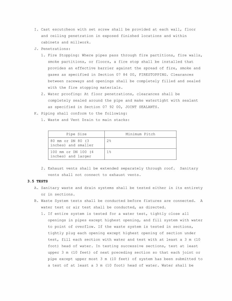
I. Cast escutcheon with set screw shall be provided at each wall, floor
and ceiling penetration in exposed finished locations and within
cabinets and millwork.
J. Penetrations:
1. Fire Stopping: Where pipes pass through fire partitions, fire walls,
smoke partitions, or floors, a fire stop shall be installed that
provides an effective barrier against the spread of fire, smoke and
gases as specified in Section 07 84 00, FIRESTOPPING. Clearances
between raceways and openings shall be completely filled and sealed
with the fire stopping materials.
2. Water proofing: At floor penetrations, clearances shall be
completely sealed around the pipe and make watertight with sealant
as specified in Section 07 92 00, JOINT SEALANTS.
K. Piping shall conform to the following:
1. Waste and Vent Drain to main stacks:
Pipe Size Minimum Pitch
80 mm or DN 80 (3 inches) and smaller
2%
100 mm or DN 100 (4 inches) and larger
1%
2. Exhaust vents shall be extended separately through roof. Sanitary
vents shall not connect to exhaust vents.
3.5 TESTS
A. Sanitary waste and drain systems shall be tested either in its entirety
or in sections.
B. Waste System tests shall be conducted before fixtures are connected. A
water test or air test shall be conducted, as directed.
1. If entire system is tested for a water test, tightly close all
openings in pipes except highest opening, and fill system with water
to point of overflow. If the waste system is tested in sections,
tightly plug each opening except highest opening of section under
test, fill each section with water and test with at least a 3 m (10
foot) head of water. In testing successive sections, test at least
upper 3 m (10 feet) of next preceding section so that each joint or
pipe except upper most 3 m (10 feet) of system has been submitted to
a test of at least a 3 m (10 foot) head of water. Water shall be
kept in the system, or in portion under test, for at least 15
minutes before inspection starts. System shall then be tight at all
joints.
2. For an air test, an air pressure of 35 kPa (5 psig) gage shall be
maintained for at least 15 minutes without leakage. A force pump and
mercury column gage shall be used for the air test.
3. After installing all fixtures and equipment, open water supply so
that all p-traps can be observed. For 15 minutes of operation, all
p-traps shall be inspected for leaks and any leaks found shall be
corrected.
3. Final Tests: Either one of the following tests may be used.
a. Smoke Test: After fixtures are permanently connected and traps
are filled with water, fill entire drainage and vent systems with
smoke under pressure of 1.3 kPa (1 inch of water) with a smoke
machine. Chemical smoke is prohibited.
b. Peppermint Test: Introduce (2 ounces) of peppermint into each
line or stack.
- - - E N D - - -

SECTION 22 40 00 PLUMBING FIXTURES
PART 1 - GENERAL
1.1 DESCRIPTION
A. Plumbing fixtures, associated trim and fittings necessary to make a
complete installation from wall or floor connections to rough piping,
and certain accessories.
1.2 RELATED WORK
A. Sealing between fixtures and other finish surfaces: Section 07 92 00,
JOINT SEALANTS.
B. Section 22 05 11, COMMON WORK RESULTS FOR PLUMBING.
1.3 SUBMITTALS
A. Submit in accordance with Section 01 33 23, SHOP DRAWINGS, PRODUCT
DATA, AND SAMPLES.
B. Submit plumbing fixture information in an assembled brochure, showing
cuts and full detailed description of each fixture.
1.4 APPLICABLE PUBLICATIONS
A. The publications listed below form a part of this specification to the
extent referenced. The publications are referenced in the text by the
basic designation only.
B. American National Standard Institute (ANSI):
The American Society of Mechanical Engineers (ASME):
A112.6.1M-02(R2008).....Floor Affixed Supports for Off-the-Floor
Plumbing Fixtures for Public Use
A112.19.2M-03...........Vitreous China Plumbing Fixtures
C. National Association of Architectural Metal Manufacturers (NAAMM):
NAAMM AMP 500-505
Metal Finishes Manual (1988)
D. National Sanitation Foundation (NSF)/American National Standards
Institute (ANSI):
61-2009 ................Drinking Water System Components-Health Effects
E. American with Disabilities Act (A.D.A) Section 4-19.4 Exposed Pipes and
Surfaces
F. Environmental Protection Agency EPA PL 93-523 1974; A 1999) Safe
Drinking Water Act.
G. International Building Code, ICC IPBC 2009.
PART 2 - PRODUCTS
2.1 STAINLESS STEEL
A. Corrosion-resistant Steel (CRS):
1. Plate, Sheet and Strip: CRS flat products shall conform to chemical
composition requirements of any 300 series steel specified in ASTM
A276.
2. Finish: Exposed surfaces shall have standard polish (ground and
polished) equal to NAAMM finish Number 4.
B. Die-cast zinc alloy products are prohibited.
2.2 STOPS
A. Provide lock-shield loose key or screw driver pattern angle stops,
straight stops or stops integral with faucet, with each compression
type faucet whether specifically called for or not. Locate stops
centrally above or below fixture in accessible location.
B. Furnish keys for lock shield stops to Resident Engineer.
C. Supply from stops not integral with faucet shall be chrome plated
copper flexible tubing or flexible stainless steel with inner core of
non-toxic polymer.
D. Supply pipe from wall to valve stop shall be rigid threaded IPS copper
alloy pipe, i.e. red brass pipe nipple, chrome plated where exposed.
2.3 ESCUTCHEONS
A. Heavy type, chrome plated, with set screws. Provide for piping serving
plumbing fixtures and at each wall, ceiling and floor penetrations in
exposed finished locations.
2.4 LAMINAR FLOW CONTROL DEVICE
A. Smooth, bright stainless steel or satin finish, chrome plated metal
laminar flow device shall provide non-aeration, clear, coherent laminar
flow that will not splash in basin. Device shall also have a flow
control restrictor and have vandal resistant housing.
B. Flow Control Restrictor:
1. Capable of restricting flow from 95 ml/s to 110 ml/s (1.5 gpm to 1.7
gpm) for lavatories; 125 ml/s to 140 ml/s (2.0 gpm to 2.2 gpm) for
sinks P-505 through P-520, P-524 and P-528; and 170 ml/s to 190 ml/s
(2.75 gpm to 3.0 gpm) for dietary food preparation and rinse sinks
or as specified.

2. Compensates for pressure fluctuation maintaining flow rate specified
above within 10 percent between 170 kPa and 550 kPa (25 psi and 80
psi).
3. Operates by expansion and contraction, eliminates mineral/sediment
build-up with self-cleaning action, and is capable of easy manual
cleaning.
2.5 CARRIERS
A. ASME/ANSI A112.6.1M, with adjustable gasket faceplate chair carriers
for wall hung closets with auxiliary anchor foot assembly, hanger rod
support feet, and rear anchor tie down.
B. ASME/ANSI A112.6.1M, lavatory, chair carrier for thin wall construction
steel plate as detailed on drawing. All lavatory chair carriers shall
be capable of supporting the lavatory with a 250-pound vertical load
applied at the front of the fixture.
C. Where urinals, lavatories or sinks are installed back-to-back and
carriers are specified, provide one carrier to serve both fixtures in
lieu of individual carriers. The drainage fitting of the back to back
carrier shall be so constructed that it prevents the discharge from one
fixture from flowing into the opposite fixture.
2.6 WATER CLOSETS
A. (P-101) Water Closet (Floor Mounted, ANSI 112.19.2M, Figure 6) -
elongated bowl, siphon jet 6 L (1.6 gallons) per flush, floor set, back
outlet. Top of rim shall be 435 mm to 438 mm (17 1/8 inches to 17 1/4
inches) above finished floor.
1. Seat: Institutional/Industrial, extra heavy duty, chemical
resistant, solid plastic, open front less cover for elongated bowls,
integrally molded bumpers, concealed check hinge with stainless
steel post. Seat shall be posture contoured body design. Color shall
be white.
2. Fittings and Accessories: Wall flange fittings-cast iron; Gasket-
wax; bolts with chromium plated cap nuts and washers.
3. Flush valve: Large chloramines resistant diaphragm, semi-red brass
valve body, exposed chrome plated, non-hold-open ADA approved side
oscillating handle, water saver design 6 L (1.6 gallons) per flush
with maximum 10 percent variance, top spud connection, adjustable
tailpiece, one-inch IPS screwdriver back check angle stop with
vandal resistant cap, high back pressure vacuum breaker, and sweat
solder adapter with cover tube and cast set screw wall flange. Set
centerline of inlet 292 mm (11 1/2 inches) above rim. Seat bumpers
shall be integral part of flush valve. Valve body, cover, tailpiece
and control stop shall be in conformance with ASTM Alloy
classification for semi-red brass.
B. (P-116) Water Closet (Floor Mounted, ANSI 112.19.2M, Figure 6) -
elongated bowl, siphon jet 6 L (1.6 gallons) per flush, floor set, back
outlet. Top of rim shall be 435 mm to 438 mm (17 1/8 inches to 17 1/4
inches) above finished floor.
1. Seat: Institutional/Industrial, extra heavy duty, chemical
resistant, solid plastic, open front less cover for elongated bowls,
integrally molded bumpers, concealed check hinge with stainless
steel post. Seat shall be posture contoured body design. Color shall
be white.
2. Fittings and Accessories: Wall flange fittings-cast iron; Gasket-
wax; bolts with chromium plated cap nuts and washers.
3. Flush valve: To be hard wired, AC powered, infrared sensor for
automatic hands free option and mechanical manual override. Provide
25 VA transformer to control up to 8 units.
2.7 URINALS
A. (P-201) Urinal (Wall Hung, ANSI A112.19.2M, Figure 30) bowl with
integral flush distribution, wall to front of flare 356 mm (14 inches).
Wall hung with integral trap, siphon jet flushing action 4 L (1.0
gallons) per flush with 50 mm (2 inches) back outlet and 19 mm (3/4
inch) top inlet spud.
1. Support urinal with chair carrier and install with rim 600 mm (24
inches) above finished floor.
2. Flushing Device: Large chloramines resistant diaphragm, semi-red
brass body, exposed flush valve non-hold-open, water saver design,
19 mm (3/4 inch) capped screwdriver angle stop valve. Set centerline
of inlet 292 mm (11 1/2 inches) above urinal. Valve body, cover,
tailpiece, and control stop shall be in conformance with ASTM alloy
classification for semi-red brass.
B. (P-202) Urinal (ADA, Wall Hung, ANSI A112.19.2M, Figure 30) bowl with
integral flush distribution, wall to front of flare 356 mm (14 inches).
Wall hung with integral trap, siphon jet flushing action 4 L (1.0
gallon per flush) with 51 mm (2 inches) back outlet and 19 mm (3/4
inch) top inlet spud.

1. Support urinal with chair carrier and install with rim 381 mm (15
inches) above finished floor.
2. Flushing Device: Large chloramines resistant diaphragm, semi-red
brass body, exposed flush valve, non-hold-open, water saver design,
19 mm (3/4 inch) capped screwdriver angle stop valve. Set centerline
of inlet 292 mm (11 1/2 inches) above urinal. Valve body, cover,
tailpiece and control stop shall be in conformance with ASTM alloy
classification for semi-red brass.
C. (P-207) Urinal (Wall Hung, ANSI A112.19.2M, Figure 30) bowl with
integral flush distribution, wall to front of flare 356 mm (14 inches).
Wall hung with integral trap, siphon jet flushing action 4 L (1.0
gallons) per flush with 50 mm (2 inches) back outlet and 19 mm (3/4
inch) top inlet spud.
1. Support urinal with chair carrier and install with rim 600 mm (24
inches) above finished floor.
2. Flush Valve: To be hard wired, AC powered, infrared sensor with
mechanical manual override. Provide 25 VA transformer to control up
to 8 units.
D. (P-208) Urinal (ADA, Wall Hung, ANSI A112.19.2M, Figure 30) bowl with
integral flush distribution, wall to front of flare 356 mm (14 inches).
Wall hung with integral trap, siphon jet flushing action 4 L (1.0
gallon per flush) with 51 mm (2 inches) back outlet and 19 mm (3/4
inch) top inlet spud.
1. Support urinal with chair carrier and install with rim 381 mm (15
inches) above finished floor.
2. Flush Valve: To be hard wired, AC powered, infrared sensor with
mechanical manual override. Provide 25 VA transformer to control up
to 8 units.
2.8 LAVATORIES
A. (P-421) Lavatory, solid surface with integral bowl specified under
another division.
1. Faucet: Solid cast brass construction, vandal resistant, heavy-duty
wrist blade handles. Control shall be washerless ceramic disc
cartridge type. Provide laminar flow control device, adjustable hot
water limit stop, and vandal proof screws. Brass components in
contact with water shall contain no more than 3 percent lead content
by dry weight.

2. Drain: Cast or wrought brass with flat grid strainer offset
tailpiece, chrome plated and chrome plated grid strainer. Provide
cover per A.D.A 4-19.4.
3. Stops: Angle type, see paragraph 2.2 Stops. Provide cover per A.D.A
4-19.4.
4. Trap: Cast copper alloy, 38 mm by 32 mm (1 1/2 inches by 1 1/4
inches) P-trap. Adjustable with connected elbow and 1.4 mm thick (17
gauge) tubing extensions to wall. Exposed metal trap surface and
connection hardware shall be chrome plated with a smooth bright
finish. Set trap parallel to wall. Provide cover per A.D.A 4-19.4.
B. (P-422) Lavatory, solid surface with integral bowl specified under
another division.
1. Faucet: Sensor activated faucet with laminar flow spray head,
thermostatic-tempering valve (below deck) with back checks. Provide
control module and hard wired transformer.
2. Drain: Cast or wrought brass with flat grid strainer offset
tailpiece, chrome plated and chrome plated grid strainer. Provide
cover per A.D.A 4-19.4.
3. Stops: Angle type, see paragraph 2.2 Stops. Provide cover per A.D.A
4-19.4.
4. Trap: Cast copper alloy, 38 mm by 32 mm (1 1/2 inches by 1 1/4
inches) P-trap. Adjustable with connected elbow and 1.4 mm thick (17
gauge) tubing extensions to wall. Exposed metal trap surface and
connection hardware shall be chrome plated with a smooth bright
finish. Set trap parallel to wall. Provide cover per A.D.A 4-19.4
2.9 SHOWER BATH FIXTURE
A. (P-701) Shower Fixture (Detachable, Wall Mounted, Concealed Supplies,
Type T/P Combination Valve:
1. Shower Installation: Wall mounted detachable spray assembly, 600 mm
(24 inch) wall bar, elevated vacuum breaker, supply elbow and flange
and valve. All external trim, chrome plated metal.
2. Shower Head Assembly: Plastic shower head with flow control to
limit discharge to 160 ml/s (2.5 gpm), 1524 mm (60 inches) length of
chrome plated metal flexible, or white vinyl reinforced hose and
supply wall below spray unit to have on/off control with a non-
positive shutoff. Design showerhead to fit in palm of hand.
Provide CRS or chrome plated metal wall bar with an adjustable

swivel hanger for showerhead. Fasten wall bar securely to wall for
hand support.
3. Valves: Type T/P combination thermostatic and pressure balancing,
with chrome plated metal lever type operating handle adjustable for
rough-in variations and chrome plated metal or CRS faceplate. Valve
body shall be any suitable copper alloy. Internal parts shall be
copper, nickel alloy, CRS or thermoplastic material. Valve inlet
and outlet shall be 13 mm (1/2 inch) IPS. Provide external
screwdriver check stops, vacuum breaker and temperature limit stops.
Set stops for a maximum temperature of 40 degrees C (105 degrees F).
All exposed fasteners shall be vandal resistant. Valve shall
provide a minimum of 160 ml/s at 310 kPa (2.5 gpm at 45 psi)
pressure drop.
4. Base: Precast terrazzo with integral stainless steel entry cap and
1/2” threshold. Tiling flange to be bonderized galvanized steel and
extend not less than 1” above shoulder. Drain body to be stainless
steel cast integral with 2” pipe connector and stainless steel
strainer plate.
2.10 DISPENSER, DRINKING WATER
A. Standard rating conditions: 10 degrees C (50 degrees F) water with 27
degrees C (80 degrees F) inlet water temperature and 32 degrees C (90
degrees F) ambient air temperature.
B. (P-609) Water Fountain: Bubbler style fully exposed dual height
stainless steel fountain, wall support bracket, vandal resistant
bubbler heads, front access wall panel.
PART 3 - EXECUTION
3.1 INSTALLATION
A. Fixture Setting: Opening between fixture and floor and wall finish
shall be sealed as specified under Section 07 92 00, JOINT SEALANTS.
B. Supports and Fastening: Secure all fixtures, equipment and trimmings to
partitions, walls and related finish surfaces. Exposed heads of bolts
and nuts in finished rooms shall be hexagonal, polished chrome plated
brass with rounded tops.
C. Through Bolts: For free standing marble and metal stud partitions refer
to Section 10 21 13, TOILET COMPARTMENTS.
D. Toggle Bolts: For hollow masonry units, finished or unfinished.
E. Expansion Bolts: For brick or concrete or other solid masonry. Shall be
6 mm (1/4 inch) diameter bolts, and to extend at least 76 mm (3 inches)

into masonry and be fitted with loose tubing or sleeves extending into
masonry. Wood plugs, fiber plugs, lead or other soft metal shields are
prohibited.
F. Power Set Fasteners: May be used for concrete walls, shall be 6 mm (1/4
inch) threaded studs, and shall extend at least 32 mm (1 1/4 inches)
into wall.
G. Tightly cover and protect fixtures and equipment against dirt, water
and chemical or mechanical injury.
H. Where water closet waste pipe has to be offset due to beam
interference, provide correct and additional piping necessary to
eliminate relocation of water closet.
I. Do not use aerators on lavatories and sinks.
3.2 CLEANING
At completion of all work, fixtures, exposed materials and equipment
shall be thoroughly cleaned.
- - - E N D - - -


SECTION 23 05 11 COMMON WORK RESULTS FOR HVAC
PART 1 - GENERAL
1.1 DESCRIPTION
A. The requirements of this Section apply to all sections of Division 23.
B. Definitions:
1. Exposed: Piping, ductwork, and equipment exposed to view in finished
rooms.
2. Option or optional: Contractor's choice of an alternate material or
method.
3. RE: Resident Engineer
4. COTR: Contracting Officer’s Technical Representative.
1.2 RELATED WORK
A. Section 01 00 00, GENERAL REQUIREMENTS
B. Section 01 33 23, SHOP DRAWINGS, PRODUCT DATA, and SAMPLES
C. Section 07 84 00, FIRESTOPPING
D. Section 07 92 00, JOINT SEALANTS
F. Section 09 91 00, PAINTING
G. Section 23 05 93, TESTING, ADJUSTING, and BALANCING FOR HVAC
H. Section 23 07 11, HVAC Insulation
I. Section 23 31 00, HVAC DUCTS
J. Section 23 37 00, AIR OUTLETS and INLETS
1.3 QUALITY ASSURANCE
A. Mechanical, electrical and associated systems shall be safe, reliable,
efficient, durable, easily and safely operable and maintainable, easily
and safely accessible, and in compliance with applicable codes as
specified. The systems shall be comprised of high quality
institutional-class and industrial-class products of manufacturers that
are experienced specialists in the required product lines. All
construction firms and personnel shall be experienced and qualified
specialists in industrial and institutional HVAC
B. Flow Rate Tolerance for HVAC Equipment: Section 23 05 93, TESTING,
ADJUSTING, AND BALANCING FOR HVAC.

C. Products Criteria:
1. Standard Products: Material and equipment shall be the standard
products of a manufacturer regularly engaged in the manufacture of
the products for at least 3 years (or longer as specified
elsewhere). The design, model and size of each item shall have been
in satisfactory and efficient operation on at least three
installations for approximately three years. However, digital
electronics devices, software and systems such as controls,
instruments, computer work station, shall be the current generation
of technology and basic design that has a proven satisfactory
service record of at least three years. See other specification
sections for any exceptions and/or additional requirements.
2. All items furnished shall be free from defects that would adversely
affect the performance, maintainability and appearance of individual
components and overall assembly.
3. Conform to codes and standards as required by the specifications.
Conform to local codes, if required by local authorities such as the
natural gas supplier, if the local codes are more stringent than
those specified. Refer any conflicts to the Resident Engineer.
4. Multiple Units: When two or more units of materials or equipment of
the same type or class are required, these units shall be products
of one manufacturer.
5. Assembled Units: Manufacturers of equipment assemblies, which use
components made by others, assume complete responsibility for the
final assembled product.
6. Nameplates: Nameplate bearing manufacturer's name or identifiable
trademark shall be securely affixed in a conspicuous place on
equipment, or name or trademark cast integrally with equipment,
stamped or otherwise permanently marked on each item of equipment.
7. Asbestos products or equipment or materials containing asbestos
shall not be used.
D. Execution (Installation, Construction) Quality:
1. Apply and install all items in accordance with manufacturer's
written instructions. Refer conflicts between the manufacturer's
instructions and the contract drawings and specifications to the
Resident Engineer for resolution. Provide written hard copies or
computer files of manufacturer’s installation instructions to the
Resident Engineer at least two weeks prior to commencing

installation of any item. Installation of the item will not be
allowed to proceed until the recommendations are received. Failure
to furnish these recommendations is a cause for rejection of the
material.
1.4 SUBMITTALS
A. Submit in accordance with Section 01 33 23, SHOP DRAWINGS, PRODUCT
DATA, AND SAMPLES, and with requirements in the individual
specification sections.
B. Contractor shall make all necessary field measurements and
investigations to assure that the equipment and assemblies will meet
contract requirements.
C. If equipment is submitted which differs in arrangement from that shown,
provide drawings that show the rearrangement of all associated systems.
Approval will be given only if all features of the equipment and
associated systems, including accessibility, are equivalent to that
required by the contract.
D. Prior to submitting shop drawings for approval, contractor shall
certify in writing that manufacturers of all major items of equipment
have each reviewed drawings and specifications, and have jointly
coordinated and properly integrated their equipment and controls to
provide a complete and efficient installation.
E. Submittals and shop drawings for interdependent items, containing
applicable descriptive information, shall be furnished together and
complete in a group. Coordinate and properly integrate materials and
equipment in each group to provide a completely compatible and
efficient.
F. Layout Drawings:
1. Submit complete consolidated and coordinated layout drawings for all
new systems, and for existing systems that are in the same areas.
2. The drawings shall include plan views, elevations and sections of
all systems and shall be on a scale of not less than 1:32 (3/8-inch
equal to one foot). Clearly identify and dimension the proposed
locations of the principal items of equipment. The drawings shall
clearly show locations and adequate clearance for all equipment,
piping, valves, control panels and other items. Show the access
means for all items requiring access for operations and maintenance.
Provide detailed layout drawings of all piping and duct systems.
G. Provide copies of approved HVAC equipment submittals to the Testing,
Adjusting and Balancing Subcontractor.
1.5 DELIVERY, STORAGE AND HANDLING
A. Protection of Equipment:
1. Equipment and material placed on the job site shall remain in the
custody of the Contractor until phased acceptance, whether or not
the Government has reimbursed the Contractor for the equipment and
material. The Contractor is solely responsible for the protection of
such equipment and material against any damage.
2. Place damaged equipment in first class, new operating condition; or,
replace same as determined and directed by the Resident Engineer.
Such repair or replacement shall be at no additional cost to the
Government.
3. Protect interiors of new equipment against entry of foreign matter.
Clean both inside and outside before painting or placing equipment
in operation.
4. Existing equipment and piping being worked on by the Contractor
shall be under the custody and responsibility of the Contractor and
shall be protected as required for new work.
1.6 JOB CONDITIONS – WORK IN EXISTING BUILDING
A. Building Operation: Government employees will be continuously operating
and managing all facilities, including temporary facilities, that serve
the medical center.
B. Maintenance of Service: Schedule all work to permit continuous service
as required by the medical center.
C. Phasing of Work: Comply with all requirements shown on drawings or
specified.
D. Building Working Environment: Maintain the architectural and structural
integrity of the building and the working environment at all times.
Maintain the interior of building at 18 degrees C (65 degrees F)
minimum. Limit the opening of doors, windows or other access openings
to brief periods as necessary for rigging purposes. Provide daily
clean-up of construction and demolition debris on all floor surfaces
and on all equipment being operated by VA.
E. Acceptance of Work for Government Operation: As new facilities are made
available for operation and these facilities are of beneficial use to
the Government, inspections will be made and tests will be performed.
Based on the inspections, a list of contract deficiencies will be

issued to the Contractor. After correction of deficiencies as necessary
for beneficial use, the Contracting Officer will process necessary
acceptance and the equipment will then be under the control and
operation of Government personnel.
PART 2 - PRODUCTS
2.1 FACTORY-ASSEMBLED PRODUCTS
A. Provide maximum standardization of components to reduce spare part
requirements.
B. Manufacturers of equipment assemblies that include components made by
others shall assume complete responsibility for final assembled unit.
1. All components of an assembled unit need not be products of same
manufacturer.
2. Constituent parts that are alike shall be products of a single
manufacturer.
3. Components shall be compatible with each other and with the total
assembly for intended service.
4. Contractor shall guarantee performance of assemblies of components,
and shall repair or replace elements of the assemblies as required
to deliver specified performance of the complete assembly.
C. Components of equipment shall bear manufacturer's name and trademark,
model number, serial number and performance data on a name plate
securely affixed in a conspicuous place, or cast integral with, stamped
or otherwise permanently marked upon the components of the equipment.
D. Major items of equipment, which serve the same function, must be the
same make and model. Exceptions will be permitted if performance
requirements cannot be met.
2.2 COMPATIBILITY OF RELATED EQUIPMENT
A. Equipment and materials installed shall be compatible in all respects
with other items being furnished and with existing items so that the
result will be a complete and fully operational plant that conforms to
contract requirements.
2.3 FIRESTOPPING
A. Section 07 84 00, FIRESTOPPING specifies an effective barrier against
the spread of fire, smoke and gases where penetrations occur for piping
and ductwork. Refer to Section 23 07 11, HVAC, PLUMBING, AND BOILER
PLANT INSULATION, for firestop pipe and duct insulation.

2.4 DUCT PENETRATIONS
A. Provide firestopping for openings through fire and smoke barriers,
maintaining minimum required rating of floor, ceiling or wall assembly.
See section 07 84 00, FIRESTOPPING.
2.5 ASBESTOS
A. Materials containing asbestos are not permitted.
PART 3 - EXECUTION
3.1 MECHANICAL DEMOLITION
A. Rigging access, other than indicated on the drawings, shall be provided
by the Contractor after approval for structural integrity by the
Resident Engineer. Such access shall be provided without additional
cost or time to the Government. Where work is in an operating plant,
provide approved protection from dust and debris at all times for the
safety of plant personnel and maintenance of plant operation and
environment of the plant.
B. In an operating facility, maintain the operation, cleanliness and
safety. Government personnel will be carrying on their normal duties of
operating, cleaning and maintaining equipment and plant operation.
Confine the work to the immediate area concerned; maintain cleanliness
and wet down demolished materials to eliminate dust. Do not permit
debris to accumulate in the area to the detriment of plant operation.
Perform all flame cutting to maintain the fire safety integrity of this
plant. Adequate fire extinguishing facilities shall be available at all
times. Perform all work in accordance with recognized fire protection
standards. Inspection will be made by personnel of the VA Medical
Center, and Contractor shall follow all directives of the RE or COTR
with regard to rigging, safety, fire safety, and maintenance of
operations.
C. Completely remove all piping, wiring, conduit, and other devices
associated with the equipment not to be re-used in the new work. This
includes all pipe, valves, fittings, insulation, and all hangers
including the top connection and any fastenings to building structural
systems. Seal all openings, after removal of equipment, pipes, ducts,
and other penetrations in roof, walls, floors, in an approved manner
and in accordance with plans and specifications where specifically
covered. Structural integrity of the building system shall be
maintained. Reference shall also be made to the drawings and
specifications of the other disciplines in the project for additional
facilities to be demolished or handled.
D. All valves including gate, globe, ball, butterfly and check, all
pressure gages and thermometers with wells shall remain Government
property and shall be removed and delivered to Resident Engineer and
stored as directed. The Contractor shall remove all other material and
equipment, devices and demolition debris under these plans and
specifications. Such material shall be removed from Government property
expeditiously and shall not be allowed to accumulate.
E. Asbestos Insulation Removal: Conform to Section 02 82 11, TRADITIONAL
ASBESTOS ABATEMENT.
- - - E N D - - -

SECTION 23 05 93 TESTING, ADJUSTING, AND BALANCING FOR HVAC
PART 1 - GENERAL
1.1 DESCRIPTION
A. Testing, adjusting, and balancing (TAB) of heating, ventilating and air
conditioning (HVAC) systems. TAB includes the following:
1. Balancing air distribution systems; adjustment of total system to
provide design performance.
2. Recording and reporting results.
B. Definitions:
1. Basic TAB used in this Section: Chapter 37, "Testing, Adjusting and
Balancing" of 2007 ASHRAE Handbook, "HVAC Applications".
2. TAB: Testing, Adjusting and Balancing; the process of checking and
adjusting HVAC systems to meet design objectives.
3. AABC: Associated Air Balance Council.
4. NEBB: National Environmental Balancing Bureau.
5. Air Systems.
6. Flow rate tolerance: The allowable percentage variation, minus to
plus, of actual flow rate from values (design) in the contract
documents.
1.2 RELATED WORK
A. Section 23 05 11, COMMON WORK RESULTS FOR HVAC: General Mechanical
Requirements.
B. Section 23 07 11, HVAC INSULATION.
C. Section 23 37 00, AIR OUTLETS AND INLETS
1.3 QUALITY ASSURANCE
A. Qualifications:
1. TAB Agency: The TAB agency shall be a subcontractor of the General
Contractor and shall report to and be paid by the General
Contractor.
2. The TAB agency shall be either a certified member of AABC or
certified by the NEBB to perform TAB service for HVAC, water
balancing and vibrations and sound testing of equipment. The
certification shall be maintained for the entire duration of duties
specified herein. If, for any reason, the agency loses subject
certification during this period, the General Contractor shall
immediately notify the Resident Engineer and submit another TAB firm
for approval. Any agency that has been the subject of disciplinary
action by either the AABC or the NEBB within the five years
preceding Contract Award shall not be eligible to perform any work
related to the TAB. All work performed in this Section and in other
related Sections by the TAB agency shall be considered invalid if
the TAB agency loses its certification prior to Contract completion,
and the successor agency’s review shows unsatisfactory work
performed by the predecessor agency.
3. TAB Specialist: The TAB specialist shall be either a member of AABC
or an experienced technician of the Agency certified by NEBB. The
certification shall be maintained for the entire duration of duties
specified herein. If, for any reason, the Specialist loses subject
certification during this period, the General Contractor shall
immediately notify the Resident Engineer and submit another TAB
Specialist for approval. Any individual that has been the subject of
disciplinary action by either the AABC or the NEBB within the five
years preceding Contract Award shall not be eligible to perform any
duties related to the HVAC systems, including TAB. All work
specified in this Section and in other related Sections performed by
the TAB specialist shall be considered invalid if the TAB Specialist
loses its certification prior to Contract completion and must be
performed by an approved successor.
4. TAB Specialist shall be identified by the General Contractor within
60 days after the notice to proceed. The TAB specialist will be
coordinating, scheduling and reporting all TAB work and related
activities and will provide necessary information as required by the
Resident Engineer. The responsibilities would specifically include:
a. Shall directly supervise all TAB work.
b. Shall sign the TAB reports that bear the seal of the TAB
standard. The reports shall be accompanied by report forms and
schematic drawings required by the TAB standard, AABC or NEBB.
c. Would follow all TAB work through its satisfactory completion.
d. Shall provide final markings of settings of all HVAC adjustment
devices.
e. Permanently mark location of duct test ports.
5. All TAB technicians performing actual TAB work shall be experienced
and must have done satisfactory work on a minimum of 3 projects
comparable in size and complexity to this project. Qualifications

must be certified by the TAB agency in writing. The lead technician
shall be certified by AABC or NEBB
B. Test Equipment Criteria: The instrumentation shall meet the
accuracy/calibration requirements established by AABC National
Standards or by NEBB Procedural Standards for Testing, Adjusting and
Balancing of Environmental Systems and instrument manufacturer. Provide
calibration history of the instruments to be used for test and balance
purpose.
C. Tab Criteria:
1. One or more of the applicable AABC, NEBB or SMACNA publications,
supplemented by ASHRAE Handbook "HVAC Applications" Chapter 36, and
requirements stated herein shall be the basis for planning,
procedures, and reports.
2. Flow rate tolerance: Following tolerances are allowed. For
tolerances not mentioned herein follow ASHRAE Handbook "HVAC
Applications", Chapter 36, as a guideline. Air Filter resistance
during tests, artificially imposed if necessary, shall be at least
100 percent of manufacturer recommended change over pressure drop
values for pre-filters and after-filters.
a. Individual room air outlets and inlets, and air flow rates not
mentioned above: Minus 5 percent to plus l0 percent except if the
air to a space is 100 CFM or less the tolerance would be minus 5
to plus 5 percent.
1.4 SUBMITTALS
A. Submit in accordance with Section 01 33 23, SHOP DRAWINGS, PRODUCT
DATA, and SAMPLES.
B. Submit names and qualifications of TAB agency and TAB specialists
within 60 days after the notice to proceed. Submit information on three
recently completed projects and a list of proposed test equipment.
C. For use by the Resident Engineer staff, submit one complete set of
applicable AABC or NEBB publications that will be the basis of TAB
work.
D. Submit Following for Review and Approval:
1. Intermediate and Final TAB reports covering flow balance and
adjustments, and performance tests.
2. Include in final reports uncorrected installation deficiencies noted
during TAB and applicable explanatory comments on test results that
differ from design requirements.

E. Prior to request for Final or Partial Final inspection, submit
completed Test and Balance report for the area.
1.5 APPLICABLE PUBLICATIONS
A. The following publications form a part of this specification to the
extent indicated by the reference thereto. In text the publications are
referenced to by the acronym of the organization.
B. American Society of Heating, Refrigerating and Air Conditioning
Engineers, Inc. (ASHRAE):
2007 ...................HVAC Applications ASHRAE Handbook, Chapter 37,
Testing, Adjusting, and Balancing and Chapter
47, Sound and Vibration Control
C. Associated Air Balance Council (AABC):
2002....................AABC National Standards for Total System
Balance
D. National Environmental Balancing Bureau (NEBB):
7th Edition 2005 ........Procedural Standards for Testing, Adjusting,
Balancing of Environmental Systems
2nd Edition 2006 .......Procedural Standards for the Measurement of
Sound and Vibration
3rd Edition 2009 ........Procedural Standards for Whole Building Systems
Commissioning of New Construction
E. Sheet Metal and Air Conditioning Contractors National Association
(SMACNA):
3rd Edition 2002 ........HVAC SYSTEMS Testing, Adjusting and Balancing
PART 2 - PRODUCTS
2.1 PLUGS
A. Provide plastic plugs to seal holes drilled in ductwork for test
purposes.
2.2 INSULATION REPAIR MATERIAL
A. See Section 23 07 11, HVAC INSULATION. Provide for repair of
insulation removed or damaged for TAB work.
PART 3 - EXECUTION
3.1 GENERAL
A. Refer to TAB Criteria in Article, Quality Assurance.
B. Obtain applicable contract documents and copies of approved submittals
for HVAC equipment.
3.2 TAB PROCEDURES
A. Tab shall be performed in accordance with the requirement of the
Standard under which TAB agency is certified by either AABC or NEBB.
B. General: During TAB all related system components shall be in full
operation. Fan and pump rotation, motor loads and equipment vibration
shall be checked and corrected as necessary before proceeding with TAB.
Set controls and/or block off parts of distribution systems to simulate
design operation of variable volume air or water systems for test and
balance work.
C. Coordinate TAB procedures with existing systems and any phased
construction completion requirements for the project. Provide TAB
reports for pre-construction air flow rate and for each phase of the
project prior to partial final inspections of each phase of the
project. Return existing areas outside the work area to pre
constructed conditions.
D. Air Balance and Equipment Test: Include fan coil units and room
diffusers/outlets/inlets.
3.3 PHASING
A. Phased Projects: Testing and Balancing Work to follow project with
areas shall be completed per the project phasing. Upon completion of
the project all areas shall have been tested and balanced per the
contract documents.
B. Existing Areas: Systems that serve areas outside of the project scope
shall not be adversely affected. Measure existing parameters where
shown to document system capacity.
- - E N D - - -

SECTION 23 07 11 HVAC INSULATION
PART 1 - GENERAL
1.1 DESCRIPTION
A. Field applied insulation for thermal efficiency and condensation
control for
1. HVAC ductwork.
2. Re-insulation of HVAC piping, ductwork, plumbing piping after
asbestos abatement.
B. Definitions
1. ASJ: All service jacket, white finish facing or jacket.
2. Air conditioned space: Space having air temperature and/or humidity
controlled by mechanical equipment.
3. Cold: Equipment, ductwork or piping handling media at design
temperature of 16 degrees C (60 degrees F) or below.
4. Concealed: Ductwork and piping above ceilings and in chases,
interstitial space, and pipe spaces.
5. Exposed: Piping, ductwork, and equipment exposed to view in finished
areas including mechanical, Boiler Plant and electrical equipment
rooms or exposed to outdoor weather. Attics and crawl spaces where
air handling units are located are considered to be mechanical
rooms. Shafts, chases, interstitial spaces, unfinished attics, crawl
spaces and pipe basements are not considered finished areas.
6. FSK: Foil-scrim-kraft facing.
7. Hot: HVAC Ductwork handling air at design temperature above 16
degrees C (60 degrees F);HVAC equipment or piping handling media
above 41 degrees C (105 degrees F); Boiler Plant breechings and
stack temperature range 150-370 degrees C(300-700 degrees F) and
piping media and equipment 32 to 230 degrees C(90 to 450 degrees F).
8. Density: kg/m3 - kilograms per cubic meter (Pcf - pounds per cubic
foot).
9. Runouts: Branch pipe connections up to 25-mm (one-inch) nominal size
to fan coil units or reheat coils for terminal units.
10. Thermal conductance: Heat flow rate through materials.
a. Flat surface: Watt per square meter (BTU per hour per square
foot).

b. Pipe or Cylinder: Watt per square meter (BTU per hour per linear
foot).
11. Thermal Conductivity (k): Watt per meter, per degree C (BTU per inch
thickness, per hour, per square foot, per degree F temperature
difference).
12. Vapor Retarder (Vapor Barrier): A material which retards the
transmission (migration) of water vapor. Performance of the vapor
retarder is rated in terms of permeance (perms). For the purpose of
this specification, vapor retarders shall have a maximum published
permeance of 0.1 perms and vapor barriers shall have a maximum
published permeance of 0.001 perms.
13. HWH: Hot water heating supply.
14. HWHR: Hot water heating return.
15. R: Pump recirculation.
16. CW: Cold water.
17. SW: Soft water.
18. HW: Hot water.
19. CH: Chilled water supply.
20. CHR: Chilled water return.
1.2 RELATED WORK
A. Section 02 82 11, TRADITIONAL ASBESTOS ABATEMENT: Insulation containing
asbestos material.
B. Section 07 84 00, FIRESTOPPING: Mineral fiber and bond breaker behind
sealant.
C. Section 23 05 11, COMMON WORK RESULTS FOR HVAC: General mechanical
requirements and items, which are common to more than one section of
Division 23.
D. Section 23 31 00, HVAC DUCTS: Ductwork, plenum and fittings.
1.3 QUALITY ASSURANCE
A. Refer to article QUALITY ASSURANCE, in Section 23 05 11.
B. Criteria:
1. Comply with NFPA 90A, particularly paragraphs 4.3.3.1 through
4.3.3.6, 4.3.10.2.6, and 5.4.6.4, parts of which are quoted as
follows:
4.3.3.1 Pipe insulation and coverings, duct coverings, duct linings, vapor retarder facings, adhesives, fasteners, tapes, and supplementary materials added to air ducts, plenums, panels, and duct silencers used in duct systems, unless otherwise provided for in 4.3.3.1.1 or 4.3.3.1.2., shall have, in the form in

which they are used, a maximum flame spread index of 25 without evidence of continued progressive combustion and a maximum smoke developed index of 50 when tested in accordance with NFPA 255, Standard Method of Test of Surface Burning Characteristics of Building Materials.
4.3.3.1.1 Where these products are to be applied with adhesives, they shall be tested with such adhesives applied, or the adhesives used shall have a maximum flame spread index of 25 and a maximum smoke developed index of 50 when in the final dry state. (See 4.2.4.2.)
4.3.3.1.2 The flame spread and smoke developed index requirements of 4.3.3.1.1 shall not apply to air duct weatherproof coverings where they are located entirely outside of a building, do not penetrate a wall or roof, and do not create an exposure hazard.
4.3.3.2 Closure systems for use with rigid and flexible air ducts tested in accordance with UL 181, Standard for Safety Factory-Made Air Ducts and Air Connectors, shall have been tested, listed, and used in accordance with the conditions of their listings, in accordance with one of the following:
(1) UL 181A, Standard for Safety Closure Systems for Use with Rigid Air Ducts and Air Connectors
(2) UL 181B, Standard for Safety Closure Systems for Use with Flexible Air Ducts and Air Connectors
4.3.3.3 Air duct, panel, and plenum coverings and linings, and pipe insulation and coverings shall not flame, glow, smolder, or smoke when tested in accordance with a similar test for pipe covering, ASTM C 411, Standard Test Method for Hot-Surface Performance of High-Temperature Thermal Insulation, at the temperature to which they are exposed in service.
4.3.3.3.1 In no case shall the test temperature be below 121°C (250°F).
4.3.3.4 Air duct coverings shall not extend through walls or floors that are required to be fire stopped or required to have a fire resistance rating, unless such coverings meet the requirements of 5.4.6.4.
4.3.3.5* Air duct linings shall be interrupted at fire dampers to prevent interference with the operation of devices.
4.3.3.6 Air duct coverings shall not be installed so as to conceal or prevent the use of any service opening.
4.3.10.2.6 Materials exposed to the airflow shall be noncombustible or limited combustible and have a maximum smoke developed index of 50 or comply with the following.
4.3.10.2.6.1 Electrical wires and cables and optical fiber cables shall be listed as noncombustible or limited combustible and have a maximum smoke developed index of 50 or shall be listed as having a maximum peak optical density of 0.5 or less, an average optical density of 0.15 or less, and a maximum flame spread distance of 1.5 m (5 ft) or less when tested in accordance with NFPA 262, Standard Method of Test for Flame Travel and Smoke of Wires and Cables for Use in Air-Handling Spaces.

4.3.10.2.6.2 Pneumatic tubing for control systems shall be listed as having a maximum peak optical density of 0.5 or less, an average optical density of 0.15 or less, and a maximum flame spread distance of 1.5 m (5 ft) or less when tested in accordance with UL 1820, Standard for Safety Fire Test of Pneumatic Tubing for Flame and Smoke Characteristics.
4.3.10.2.6.4 Optical-fiber and communication raceways shall be listed as having a maximum peak optical density of 0.5 or less, an average optical density of 0.15 or less, and a maximum flame spread distance of 1.5 m (5 ft) or less when tested in accordance with UL 2024, Standard for Safety Optical-Fiber Cable Raceway.
4.3.10.2.6.6 Supplementary materials for air distribution systems shall be permitted when complying with the provisions of 4.3.3.
5.4.6.4 Where air ducts pass through walls, floors, or partitions that are required to have a fire resistance rating and where fire dampers are not required, the opening in the construction around the air duct shall be as follows:
(1) Not exceeding a 25.4 mm (1 in.) average clearance on all sides
(2) Filled solid with an approved material capable of preventing the passage of flame and hot gases sufficient to ignite cotton waste when subjected to the time-temperature fire conditions required for fire barrier penetration as specified in NFPA 251, Standard Methods of Tests of Fire Endurance of Building Construction and Materials
2. Test methods: ASTM E84, UL 723, or NFPA 255.
3. Specified k factors are at 24 degrees C (75 degrees F) mean
temperature unless stated otherwise. Where optional thermal
insulation material is used, select thickness to provide thermal
conductance no greater than that for the specified material. For
pipe, use insulation manufacturer's published heat flow tables. For
domestic hot water supply and return, run out insulation and
condensation control insulation, no thickness adjustment need be
made.
4. All materials shall be compatible and suitable for service
temperature, and shall not contribute to corrosion or otherwise
attack surface to which applied in either the wet or dry state.
C. Every package or standard container of insulation or accessories
delivered to the job site for use must have a manufacturer's stamp or
label giving the name of the manufacturer and description of the
material.
1.4 SUBMITTALS
A. Submit in accordance with Section 01 33 23, SHOP DRAWINGS, PRODUCT
DATA, and SAMPLES.

B. Shop Drawings:
1. All information, clearly presented, shall be included to determine
compliance with drawings and specifications and ASTM, federal and
military specifications.
a. Insulation materials: Specify each type used and state surface
burning characteristics.
b. Insulation facings and jackets: Each type used. Make it clear
that white finish will be furnished for exposed ductwork, casings
and equipment.
c. Insulation accessory materials: Each type used.
d. Manufacturer's installation and fitting fabrication instructions
for flexible unicellular insulation.
e. Make reference to applicable specification paragraph numbers for
coordination.
1.5 STORAGE AND HANDLING OF MATERIAL
A. Store materials in clean and dry environment, pipe covering jackets
shall be clean and unmarred. Place adhesives in original containers.
Maintain ambient temperatures and conditions as required by printed
instructions of manufacturers of adhesives, mastics and finishing
cements.
1.6 APPLICABLE PUBLICATIONS
A. The publications listed below form a part of this specification to the
extent referenced. The publications are referenced in the text by basic
designation only.
B. Military Specifications (Mil. Spec.):
MIL-A-3316C (2)-90......Adhesives, Fire-Resistant, Thermal Insulation
C. American Society for Testing and Materials (ASTM):
C547-07.................Standard Specification for Mineral Fiber pipe
Insulation
C553-08.................Standard Specification for Mineral Fiber
Blanket Thermal Insulation for Commercial and
Industrial Applications
C1136-10................Standard Specification for Flexible, Low
Permeance Vapor Retarders for Thermal
Insulation
D1668-97a (2006)........Standard Specification for Glass Fabrics (Woven
and Treated) for Roofing and Waterproofing

E84-10..................Standard Test Method for Surface Burning
Characteristics of Building
Materials
E119-09c................Standard Test Method for Fire Tests of Building
Construction and Materials
D. National Fire Protection Association (NFPA):
90A-09..................Standard for the Installation of Air
Conditioning and Ventilating Systems
101-09..................Life Safety Code
251-06..................Standard methods of Tests of Fire Endurance of
Building Construction Materials
255-06..................Standard Method of tests of Surface Burning
Characteristics of Building Materials
F. Underwriters Laboratories, Inc (UL):
723.....................UL Standard for Safety Test for Surface Burning
Characteristics of Building Materials with
Revision of 09/08
PART 2 - PRODUCTS
2.1 MINERAL FIBER OR FIBER GLASS
A. ASTM C553 (Blanket, Flexible) Type I, Class B-3, Density 16 kg/m3 (1
pcf), k = 0.045 (0.31 or Class B-5, Density 32 kg/m3 (2 pcf), k = 0.04
(0.27) at 24 degrees C (75 degrees F), for use at temperatures up to
204 degrees C (400 degrees F) with foil scrim (FSK) facing.
B. ASTM C547 (Pipe Fitting Insulation and Preformed Pipe Insulation),
Class 1, k = 0.037 (0.26) at 24 degrees C (75 degrees F), for use at
temperatures up to 230 degrees C (450 degrees F) with an all service
vapor retarder jacket with polyvinyl chloride premolded fitting
covering.
2.2 INSULATION FACINGS AND JACKETS
A. Vapor Retarder, higher strength with low water permeance = 0.02 or less
perm rating, Beach puncture 50 units for insulation facing on exposed
ductwork, casings and equipment, and for pipe insulation jackets.
Facings and jackets shall be all service type (ASJ) or PVDC Vapor
Retarder jacketing.
B. ASJ jacket shall be white kraft bonded to 0.025 mm (1 mil) thick
aluminum foil, fiberglass reinforced, with pressure sensitive adhesive
closure. Comply with ASTM C1136. Beach puncture 50 units, Suitable for

painting without sizing. Jackets shall have minimum 40 mm (1-1/2 inch)
lap on longitudinal joints and minimum 75 mm (3 inch) butt strip on end
joints. Butt strip material shall be same as the jacket. Lap and butt
strips shall be self-sealing type with factory-applied pressure
sensitive adhesive.
C. Vapor Retarder medium strength with low water vapor permeance of 0.02
or less perm rating), Beach puncture 25 units: Foil-Scrim-Kraft (FSK)
or PVDC vapor retarder jacketing type for concealed ductwork and
equipment.
D. Factory composite materials may be used provided that they have been
tested and certified by the manufacturer.
E. Pipe fitting insulation covering (jackets): Fitting covering shall be
premolded to match shape of fitting and shall be polyvinyl chloride
(PVC) conforming to Fed Spec L-P-335, composition A, Type II Grade GU,
and Type III, minimum thickness 0.7 mm (0.03 inches). Provide color
matching vapor retarder pressure sensitive tape.
2.3 PIPE COVERING PROTECTION SADDLES
A. Cold pipe support: Premolded pipe insulation 180 degrees (half-shells)
on bottom half of pipe at supports. Material shall be cellular glass or
high density Polyisocyanurate insulation of the same thickness as
adjacent insulation. Density of Polyisocyanurate insulation shall be a
minimum of 48 kg/m3 (3.0 pcf).
Nominal Pipe Size and Accessories Material (Insert Blocks)
Nominal Pipe Size mm (inches) Insert Blocks mm (inches)
Up through 125 (5) 150 (6) long
150 (6) 150 (6) long
200 (8), 250 (10), 300 (12) 225 (9) long
350 (14), 400 (16) 300 (12) long
450 through 600 (18 through 24) 350 (14) long
B. Warm or hot pipe supports: Premolded pipe insulation (180 degree half-
shells) on bottom half of pipe at supports. Material shall be high
density Polyisocyanurate (for temperatures up to 149 degrees C [300
degrees F]), cellular glass or calcium silicate. Insulation at
supports shall have same thickness as adjacent insulation. Density of
Polyisocyanurate insulation shall be a minimum of 48 kg/m3 (3.0 pcf).

2.4 REINFORCEMENT AND FINISHES
A. PVC fitting cover: Fed. Spec L-P-535, Composition A, 11-86 Type II,
Grade GU, with Form B Mineral Fiber insert, for media temperature 4
degrees C (40 degrees F) to 121 degrees C (250 degrees F). Below 4
degrees C (40 degrees F) and above 121 degrees C (250 degrees F).
Provide double layer insert. Provide color matching vapor barrier
pressure sensitive tape.
2.5 FIRESTOPPING MATERIAL
A. Other than pipe and duct insulation, refer to Section 07 84 00
FIRESTOPPING.
2.6 FLAME AND SMOKE
A. Unless shown otherwise all assembled systems shall meet flame spread 25
and smoke developed 50 rating as developed under ASTM, NFPA and UL
standards and specifications. See paragraph 1.3 "Quality Assurance".
PART 3 - EXECUTION
3.1 GENERAL REQUIREMENTS
A. Required pressure tests of duct and piping joints and connections shall
be completed and the work approved by the Resident Engineer for
application of insulation. Surface shall be clean and dry with all
foreign materials, such as dirt, oil, loose scale and rust removed.
B. Except for specific exceptions, insulate entire specified equipment,
piping (pipe, fittings, valves, accessories), and duct systems.
Insulate each pipe and duct individually. Do not use scrap pieces of
insulation where a full length section will fit.
C. Where removal of insulation of piping, ductwork and equipment is
required to comply with Section 02 82 11, TRADITIONAL ASBESTOS
ABATEMENT and Section 02 82 13.13, GLOVEBAG ASBESTOS ABATEMENT, such
areas shall be reinsulated to comply with this specification.
D. Insulation materials shall be installed in a first class manner with
smooth and even surfaces, with jackets and facings drawn tight and
smoothly cemented down at all laps. Insulation shall be continuous
through all sleeves and openings, except at fire dampers and duct
heaters (NFPA 90A). Vapor retarders shall be continuous and
uninterrupted throughout systems with operating temperature 16 degrees
C (60 degrees F) and below. Lap and seal vapor retarder over ends and
exposed edges of insulation. Anchors, supports and other metal

projections through insulation on cold surfaces shall be insulated and
vapor sealed for a minimum length of 150 mm (6 inches).
E. Install vapor stops at all insulation terminations on either side of
valves, pumps and equipment and particularly in straight lengths of
pipe insulation.
F. Insulation on hot piping and equipment shall be terminated square at
items not to be insulated, access openings and nameplates. Cover all
exposed raw insulation with white sealer or jacket material.
G. Protect all insulations outside of buildings with aluminum jacket using
lock joint or other approved system for a continuous weather tight
system. Access doors and other items requiring maintenance or access
shall be removable and sealable.
H. HVAC work not to be insulated:
1. Internally insulated ductwork.
3. Exhaust air ducts and plenums.
I. Apply insulation materials subject to the manufacturer's recommended
temperature limits. Apply adhesives, mastic and coatings at the
manufacturer's recommended minimum coverage.
J. Elbows, flanges and other fittings shall be insulated with the same
material as is used on the pipe straights. The elbow fitting
insulation shall be field-fabricated, mitered or factory prefabricated
to the necessary size and shape to fit on the elbow fitting. Use of
polyurethane spray-foam to fill a PVC elbow jacket is prohibited on
cold applications.
K. Firestop Pipe and Duct insulation:
1. Provide firestopping insulation at fire and smoke barriers through
penetrations. Fire stopping insulation shall be UL listed as defines
in Section 07 84 00, FIRESTOPPING.
2. Pipe and duct penetrations requiring fire stop insulation including,
but not limited to the following:
a. Pipe risers through floors
b. Pipe or duct chase walls and floors
c. Smoke partitions
d. Fire partitions
L. Provide vapor barrier jackets over insulation as follows:
1. All interior piping and ducts conveying fluids exposed to outdoor
air (i.e. in attics, ventilated (not air conditioned) spaces, etc.)
below ambient air temperature in high humidity areas.

3.2 INSULATION INSTALLATION
A. Flexible Mineral Fiber Blanket:
1. Adhere insulation to metal with 75 mm (3 inch) wide strips of
insulation bonding adhesive at 200 mm (8 inches) on center all
around duct. Additionally secure insulation to bottom of ducts
exceeding 600 mm (24 inches) in width with pins welded or adhered on
450 mm (18 inch) centers. Secure washers on pins. Butt insulation
edges and seal joints with laps and butt strips. Staples may be used
to assist in securing insulation. Seal all vapor retarder
penetrations with mastic. Sagging duct insulation will not be
acceptable. Install firestop duct insulation where required.
2. Supply air ductwork to be insulated includes main and branch ducts
from AHU discharge to room supply outlets, and the bodies of ceiling
outlets to prevent condensation. To prevent condensation insulate
trapeze type supports and angle iron hangers for flat oval ducts
that are in direct contact with metal duct.
3. Concealed supply air ductwork.
a. Above ceilings for other than roof level: 40 mm (1 ½ inch) thick
insulation faced with FSK.
B. Molded Mineral Fiber Pipe and Tubing Covering:
1. Fit insulation to pipe or duct, aligning longitudinal joints. Seal
longitudinal joint laps and circumferential butt strips by rubbing
hard with a nylon sealing tool to assure a positive seal. Staples
may be used to assist in securing insulation. Seal all vapor
retarder penetrations on cold piping with a generous application of
vapor barrier mastic. Provide inserts and install with metal
insulation shields at outside pipe supports.
3.3 APPLICATION –BOILER PLANT, PIPE, VALVES, STRAINERS AND FITTINGS:
A. Temperature range 32 to 99 degrees C (90 to 211 degrees F):
1. Insulation Jacket:
a. Mineral fiber or rigid closed-cell phenolic foam for remaining
locations.
c. ASJ with PVC premolded fitting coverings.
2. Thickness-mineral fiber insulation:

Nominal Thickness Of Insulation
Pipe Diameter mm (in) Insulation Thickness mm (in)
25 (1 and below) 38 (1.5)
25 to 38 (1-1/4 to 1-1/2) 50(2)
38 (1-1/2) and above 75 (3)
B. Installation:
1. On mineral fiber systems, insulate welded and threaded fittings more
than 50 mm (2 inches) in diameter with compressed blanket insulation
(minimum 2/1) and finish with jacket or PVC cover.
2. Insulate fittings 50 mm (2 inches) and smaller with mastic finishing
material and cover with jacket.
3.4 PIPE INSULATION SCHEDULE
Provide insulation for piping systems as scheduled below:
Insulation Thickness Millimeters (Inches) Nominal Pipe Size Millimeters (Inches) Operating Temperature Range/Service
Insulation Material
Less than 25 (1)
25 – 32 (1 – 1¼)
38 – 75 (1½ - 3)
100 (4) and Above
38-94 degrees C (100-200 degrees F) (HWH, HWHR)
Mineral Fiber (Above ground piping only)
38 (1.5)
38 (1.5) 50 (2.0) 50 (2.0)
- - - E N D - - -

SECTION 23 31 00 HVAC DUCTS
PART 1 - GENERAL
1.1 DESCRIPTION
A. Ductwork and accessories for HVAC including the following:
1. Supply air, return air, and exhaust.
B. Definitions:
1. SMACNA Standards as used in this specification means the HVAC Duct
Construction Standards, Metal and Flexible.
2. Seal or Sealing: Use of liquid or mastic sealant, with or without
compatible tape overlay, or gasketing of flanged joints, to keep air
leakage at duct joints, seams and connections to an acceptable
minimum.
3. Duct Pressure Classification: SMACNA HVAC Duct Construction
Standards, Metal and Flexible.
4. Exposed Duct: Exposed to view in a finished room, exposed to
weather.
1.2 RELATED WORK
A. Fire Stopping Material: Section 07 84 00, FIRESTOPPING.
B. General Mechanical Requirements: Section 23 05 11, COMMON WORK RESULTS
FOR HVAC.
C. Duct Insulation: Section 23 07 11, HVAC INSULATION
D. Testing and Balancing of Air Flows: Section 23 05 93, TESTING,
ADJUSTING, and BALANCING FOR HVAC.
1.3 QUALITY ASSURANCE
A. Refer to article, QUALITY ASSURANCE, in Section 23 05 11, COMMON WORK
RESULTS FOR HVAC.
B. Fire Safety Code: Comply with NFPA 90A.
C. Duct System Construction and Installation: Referenced SMACNA Standards
are the minimum acceptable quality.
D. Duct Sealing, Air Leakage Criteria, and Air Leakage Tests: Ducts shall
be sealed as per duct sealing requirements of SMACNA HVAC Air Duct
Leakage Test Manual for duct pressure classes shown on the drawings.
E. Duct accessories exposed to the air stream, such as dampers of all
types (except smoke dampers) and access openings, shall be of the same
material as the duct or provide at least the same level of corrosion
resistance.

1.4 SUBMITTALS
A. Submit in accordance with Section 01 33 23, SHOP DRAWINGS, PRODUCT
DATA, and SAMPLES.
B. Manufacturer's Literature and Data:
1. Rectangular ducts:
a. Schedules of duct systems, materials and selected SMACNA
construction alternatives for joints, sealing, gage and
reinforcement.
b. Duct liner.
c. Sealants and gaskets.
d. Access doors.
2. Round and flat oval duct construction details:
a. Manufacturer's details for duct fittings.
b. Duct liner.
c. Sealants and gaskets.
d. Access sections.
e. Installation instructions.
3. Volume dampers, back draft dampers.
4. Upper hanger attachments.
5. Fire dampers, fire doors, and smoke dampers with installation
instructions.
6. Sound attenuators, including pressure drop and acoustic performance.
7. Flexible ducts and clamps, with manufacturer's installation
instructions.
8. Flexible connections.
9. Instrument test fittings.
10 Details and design analysis of alternate or optional duct systems.
11 COMMON WORK RESULTS FOR HVAC and STEAM GENERATION.
1.5 APPLICABLE PUBLICATIONS
A. The publications listed below form a part of this specification to the
extent referenced. The publications are referenced in the text by the
basic designation only.
B. American Society of Civil Engineers (ASCE):
ASCE7-05................Minimum Design Loads for Buildings and Other
Structures
C. American Society for Testing and Materials (ASTM):

A167-99(2009)...........Standard Specification for Stainless and
Heat-Resisting Chromium-Nickel Steel Plate,
Sheet, and Strip
A653-09.................Standard Specification for Steel Sheet,
Zinc-Coated (Galvanized) or Zinc-Iron Alloy
coated (Galvannealed) by the Hot-Dip process
A1011-09a...............Standard Specification for Steel, Sheet and
Strip, Hot rolled, Carbon, structural, High-
Strength Low-Alloy, High Strength Low-Alloy
with Improved Formability, and Ultra-High
Strength
B209-07.................Standard Specification for Aluminum and
Aluminum-Alloy Sheet and Plate
C1071-05e1..............Standard Specification for Fibrous Glass Duct
Lining Insulation (Thermal and Sound Absorbing
Material)
E84-09a.................Standard Test Method for Surface Burning
Characteristics of Building Materials
D. National Fire Protection Association (NFPA):
90A-09..................Standard for the Installation of Air
Conditioning and Ventilating Systems
E. Sheet Metal and Air Conditioning Contractors National Association
(SMACNA):
2nd Edition – 2005......HVAC Duct Construction Standards, Metal and
Flexible
1st Edition - 1985......HVAC Air Duct Leakage Test Manual
F. Underwriters Laboratories, Inc. (UL):
181-08..................Factory-Made Air Ducts and Air Connectors
555-06 .................Standard for Fire Dampers
555S-06 ................Standard for Smoke Dampers
PART 2 - PRODUCTS
2.1 DUCT MATERIALS AND SEALANTS
A. General: Except for systems specified otherwise, construct ducts, and
accessories of galvanized sheet steel, ASTM A653, coating G90.
B. Joint Sealing: Refer to SMACNA HVAC Duct Construction Standards,
paragraph S1.9.
1. Sealant: Elastomeric compound, gun or brush grade, maximum 25 flame
spread and 50 smoke developed (dry state) compounded specifically

for sealing ductwork as recommended by the manufacturer. Generally
provide liquid sealant, with or without compatible tape, for low
clearance slip joints and heavy, permanently elastic, mastic type
where clearances are larger. Oil base caulking and glazing compounds
are not acceptable because they do not retain elasticity and bond.
2. Tape: Use only tape specifically designated by the sealant
manufacturer and apply only over wet sealant. Pressure sensitive
tape shall not be used on bare metal or on dry sealant.
3. Gaskets in Flanged Joints: Soft neoprene.
C. Approved factory made joints may be used.
2.2 DUCT CONSTRUCTION AND INSTALLATION
A. Regardless of the pressure classifications outlined in the SMACNA
Standards, fabricate and seal the ductwork in accordance with the
following pressure classifications:
B. Duct Pressure Classification:
0 to 50 mm (2 inch)
> 50 mm to 75 mm (2 inch to 3 inch)
> 75 mm to 100 mm (3 inch to 4 inch)
Show pressure classifications on the floor plans.
C. Seal Class: All ductwork shall receive Class A Seal
D. Duct for Negative Pressure Up to 750 Pa (3 inch W.G.):
1. Round Duct: Galvanized steel, spiral lock seam construction with
standard slip joints.
2. Rectangular Duct: Galvanized steel, minimum 1.0 mm (20 gage),
Pittsburgh lock seam, companion angle joints 32 mm by 3.2 mm (1-1/4
by 1/8 inch) minimum at not more than 2.4 m (8 feet) spacing.
Approved pre-manufactured joints are acceptable in lieu of companion
angles.
E. Round and Flat Oval Ducts: Furnish duct and fittings made by the same
manufacturer to insure good fit of slip joints. When submitted and
approved in advance, round and flat oval duct, with size converted on
the basis of equal pressure drop, may be furnished in lieu of
rectangular duct design shown on the drawings.
1. Elbows: Diameters 80 through 200 mm (3 through 8 inches) shall be
two sections die stamped, all others shall be gored construction,
maximum 18 degree angle, with all seams continuously welded or
standing seam. Coat galvanized areas of fittings damaged by welding

with corrosion resistant aluminum paint or galvanized repair
compound.
2. Provide bell mouth, conical tees or taps, laterals, reducers, and
other low loss fittings as shown in SMACNA HVAC Duct Construction
Standards.
3. Ribbed Duct Option: Lighter gage round/oval duct and fittings may be
furnished provided certified tests indicating that the rigidity and
performance is equivalent to SMACNA standard gage ducts are
submitted.
a. Ducts: Manufacturer's published standard gage, G90 coating,
spiral lock seam construction with an intermediate standing rib.
b. Fittings: May be manufacturer's standard as shown in published
catalogs, fabricated by spot welding and bonding with neoprene
base cement or machine formed seam in lieu of continuous welded
seams.
4. Provide flat side reinforcement of oval ducts as recommended by the
manufacturer and SMACNA HVAC Duct Construction Standard S3.13.
Because of high pressure loss, do not use internal tie-rod
reinforcement unless approved by the Resident Engineer.
F. Volume Dampers: Single blade or opposed blade, multi-louver type as
detailed in SMACNA Standards. Refer to SMACNA Detail Figure 2-12 for
Single Blade and Figure 2.13 for Multi-blade Volume Dampers.
G. Duct Hangers and Supports: Refer to SMACNA Standards Section IV. Avoid
use of trapeze hangers for round duct.
H. Ductwork in excess of 620 cm2 (96 square inches) shall be protected
unless the duct has one dimension less than 150 mm (6 inches)if it
passes through the areas listed below. Refer to the Mission Critical
Physical Design Manual for VA Facilities. This applies to the
following:
1. Agent cashier spaces
2. Perimeter partitions of caches
3. Perimeter partitions of computer rooms
4. Perimeter of a COOP sites
5. Perimeter partitions of Entrances
6. Security control centers (SCC)
2.3 DUCT LINER (WHERE INDICATED ON DRAWINGS)
A. Duct sizes shown on drawings for lined duct are clear opening inside
lining.

B. Duct liner is only permitted to be used for return, relief and general
exhaust ducts. Duct liner is not permitted for outside air ducts,
supply air ducts or any other positive pressure ductwork (provide
exterior insulation only).
C. Rectangular Duct or Casing Liner: ASTM C1071, Type I (flexible), or
Type II (board), 25 mm (one inch) minimum thickness, applied with
mechanical fasteners and 100 percent coverage of adhesive in
conformance with SMACNA, Duct Liner Application Standard.
2.4 DUCT ACCESS DOORS, PANELS AND SECTIONS
A. Provide access doors, sized and located for maintenance work, upstream,
in the following locations:
1. Each duct mounted coil and humidifier.
2. Each fire damper (for link service), smoke damper and automatic
control damper.
3. Each duct mounted smoke detector.
4. For cleaning operating room supply air duct and kitchen hood exhaust
duct, locate access doors at 6 m (20 feet) intervals and at each
change in duct direction.
B. Openings shall be as large as feasible in small ducts, 300 mm by 300 mm
(12 inch by 12 inch) minimum where possible. Access sections in
insulated ducts shall be double-wall, insulated. Transparent
shatterproof covers are preferred for uninsulated ducts.
1. For rectangular ducts: Refer to SMACNA HVAC Duct Construction
Standards (Figure 2-12).
2. For round and flat oval duct: Refer to SMACNA HVAC duct Construction
Standards (Figure 2-11).
2.5 FLEXIBLE AIR DUCT
A. General: Factory fabricated, complying with NFPA 90A for connectors not
passing through floors of buildings. Flexible ducts shall not penetrate
any fire or smoke barrier which is required to have a fire resistance
rating of one hour or more. Flexible duct length shall not exceed 1.5 m
(5 feet). Provide insulated acoustical air duct connectors in supply
air duct systems and elsewhere as shown.
B. Flexible ducts shall be listed by Underwriters Laboratories, Inc.,
complying with UL 181. Ducts larger than 200 mm (8 inches) in diameter
shall be Class 1. Ducts 200 mm (8 inches) in diameter and smaller may
be Class 1 or Class 2.

C. Insulated Flexible Air Duct: Factory made including mineral fiber
insulation with maximum C factor of 0.25 at 24 degrees C (75 degrees F)
mean temperature, encased with a low permeability moisture barrier
outer jacket, having a puncture resistance of not less than 50 Beach
Units. Acoustic insertion loss shall not be less than 3 dB per 300 mm
(foot) of straight duct, at 500 Hz, based on 150 mm (6 inch) duct, of
750 m/min (2500 fpm).
D. Application Criteria:
1. Temperature range: -18 to 93 degrees C (0 to 200 degrees F)
internal.
2. Maximum working velocity: 1200 m/min (4000 feet per minute).
3. Minimum working pressure, inches of water gage: 2500 Pa (10 inches)
positive, 500 Pa (2 inches) negative.
E. Duct Clamps: 100 percent nylon strap, 80 kg (175 pounds) minimum loop
tensile strength manufactured for this purpose or stainless steel strap
with cadmium plated worm gear tightening device. Apply clamps with
sealant and as approved for UL 181, Class 1 installation.
2.6 FLEXIBLE DUCT CONNECTIONS
A. Where duct connections are made to fans, air terminal units, and air
handling units, install a non-combustible flexible connection of 822 g
(29 ounce) neoprene coated fiberglass fabric approximately 150 mm (6
inches) wide. For connections exposed to sun and weather provide
hypalon coating in lieu of neoprene. Burning characteristics shall
conform to NFPA 90A. Securely fasten flexible connections to round
ducts with stainless steel or zinc-coated iron draw bands with worm
gear fastener. For rectangular connections, crimp fabric to sheet metal
and fasten sheet metal to ducts by screws 50 mm (2 inches) on center.
Fabric shall not be stressed other than by air pressure. Allow at least
25 mm (one inch) slack to insure that no vibration is transmitted.
2.7 FIRESTOPPING MATERIAL
A. Refer to Section 07 84 00, FIRESTOPPING.
PART 3 - EXECUTION
3.1 INSTALLATION
A. Comply with provisions of Section 23 05 11, COMMON WORK RESULTS FOR
HVAC, particularly regarding coordination with other trades and work in
existing buildings.

B. Fabricate and install ductwork and accessories in accordance with
referenced SMACNA Standards:
1. Drawings show the general layout of ductwork and accessories but do
not show all required fittings and offsets that may be necessary to
connect ducts to equipment, boxes, diffusers, grilles, etc., and to
coordinate with other trades. Fabricate ductwork based on field
measurements. Provide all necessary fittings and offsets at no
additional cost to the government. Coordinate with other trades for
space available and relative location of HVAC equipment and
accessories on ceiling grid. Duct sizes on the drawings are inside
dimensions which shall be altered by Contractor to other dimensions
with the same air handling characteristics where necessary to avoid
interferences and clearance difficulties.
2. Provide duct transitions, offsets and connections to dampers, coils,
and other equipment in accordance with SMACNA Standards, Section II.
Provide streamliner, when an obstruction cannot be avoided and must
be taken in by a duct. Repair galvanized areas with galvanizing
repair compound.
3. Provide bolted construction and tie-rod reinforcement in accordance
with SMACNA Standards.
C. Install duct hangers and supports in accordance with SMACNA Standards,
Chapter 4.
D. Seal openings around duct penetrations of floors and fire rated
partitions with fire stop material as required by NFPA 90A.
E. Flexible duct installation: Refer to SMACNA Standards, Chapter 3. Ducts
shall be continuous, single pieces not over 1.5 m (5 feet) long (NFPA
90A), as straight and short as feasible, adequately supported.
Centerline radius of bends shall be not less than two duct diameters.
Make connections with clamps as recommended by SMACNA. Clamp per SMACNA
with one clamp on the core duct and one on the insulation jacket.
Flexible ducts shall not penetrate floors, or any chase or partition
designated as a fire or smoke barrier, including corridor partitions
fire rated one hour or two hour. Support ducts SMACNA Standards.
F. Where diffusers, registers and grilles cannot be installed to avoid
seeing inside the duct, paint the inside of the duct with flat black
paint to reduce visibility.
G. Low Pressure Duct Liner: Install in accordance with SMACNA, Duct Liner
Application Standard.

H. Protection and Cleaning: Adequately protect equipment and materials
against physical damage. Place equipment in first class operating
condition, or return to source of supply for repair or replacement, as
determined by Resident Engineer. Protect equipment and ducts during
construction against entry of foreign matter to the inside and clean
both inside and outside before operation and painting. When new ducts
are connected to existing ductwork, clean both new and existing
ductwork by mopping and vacuum cleaning inside and outside before
operation.
3.2 DUCT LEAKAGE TESTS AND REPAIR
A. Ductwork leakage testing shall be performed by the Testing and
Balancing Contractor directly contracted by the General Contractor and
independent of the Sheet Metal Contractor.
B. Ductwork leakage testing shall be performed for the entire air
distribution system (including all supply, return, exhaust and relief
ductwork), section by section, including fans, coils and filter
sections. Based upon satisfactory initial duct leakage test results,
the scope of the testing may be reduced by the Resident Engineer on
ductwork constructed to the 500 Pa (2" WG) duct pressure
classification. In no case shall the leakage testing of ductwork
constructed above the 500 Pa (2" WG) duct pressure classification or
ductwork located in shafts or other inaccessible areas be eliminated.
C. Test procedure, apparatus and report shall conform to SMACNA Leakage
Test manual. The maximum leakage rate allowed is 4 percent of the
design air flow rate.
D. All ductwork shall be leak tested first before enclosed in a shaft or
covered in other inaccessible areas.
E. All tests shall be performed in the presence of the Resident Engineer
and the Test and Balance agency. The Test and Balance agency shall
measure and record duct leakage and report to the Resident Engineer and
identify leakage source with excessive leakage.
F. If any portion of the duct system tested fails to meet the permissible
leakage level, the Contractor shall rectify sealing of ductwork to
bring it into compliance and shall retest it until acceptable leakage
is demonstrated to the Resident Engineer.
G. All tests and necessary repairs shall be completed prior to insulation
or concealment of ductwork.
H. Make sure all openings used for testing flow and temperatures by TAB
Contractor are sealed properly.
3.3 TESTING, ADJUSTING AND BALANCING (TAB)
A. Refer to Section 23 05 93, TESTING, ADJUSTING, and BALANCING FOR HVAC.
- - - E N D - - -

SECTION 23 37 00 AIR OUTLETS AND INLETS
PART 1 - GENERAL
1.1 DESCRIPTION
A. Roof Curbs
B. Air Outlets and Inlets: Diffusers, Registers, and Grilles.
1.2 RELATED WORK
A. General Mechanical Requirements: Section 23 05 11, COMMON WORK RESULTS
FOR HVAC.
B. Testing and Balancing of Air Flows: Section 23 05 93, TESTING,
ADJUSTING, AND BALANCING FOR HVAC.
1.3 QUALITY ASSURANCE
A. Refer to article, QUALITY ASSURANCE, in Section 23 05 11, COMMON WORK
RESULTS FOR HVAC.
B. Fire Safety Code: Comply with NFPA 90A.
1.4 SUBMITTALS
A. Submit in accordance with Section 01 33 23, SHOP DRAWINGS, PRODUCT
DATA, and SAMPLES.
B. Manufacturer's Literature and Data:
1. Diffusers, registers, grilles and accessories.
1.5 APPLICABLE PUBLICATIONS
A. The publications listed below form a part of this specification to the
extent referenced. The publications are referenced in the text by the
basic designation only.
B. Air Diffusion Council Test Code:
1062 GRD-84.............Certification, Rating, and Test Manual 4th
Edition
C. American Society of Civil Engineers (ASCE):
ASCE7-05................Minimum Design Loads for Buildings and Other
Structures
D. American Society for Testing and Materials (ASTM):
A167-99 (2004)..........Standard Specification for Stainless and
Heat-Resisting Chromium-Nickel Steel Plate,
Sheet and Strip
B209-07.................Standard Specification for Aluminum and
Aluminum-Alloy Sheet and Plate

E. National Fire Protection Association (NFPA):
90A-09..................Standard for the Installation of Air
Conditioning and Ventilating Systems
F. Underwriters Laboratories, Inc. (UL):
181-08..................UL Standard for Safety Factory-Made Air Ducts
and Connectors
PART 2 - PRODUCTS
2.1 AIR OUTLETS AND INLETS
A. Materials:
1. Steel or aluminum. Provide manufacturer's standard gasket.
2. Exposed Fastenings: The same material as the respective inlet or
outlet. Fasteners for aluminum may be stainless steel.
3. Contractor shall review all ceiling drawings and details and provide
all ceiling mounted devices with appropriate dimensions and trim for
the specific locations.
B. Performance Test Data: In accordance with Air Diffusion Council Code
1062GRD.
C. Air Supply Outlets:
1. Ceiling Diffusers: Suitable for surface mounting, exposed T-bar or
special tile ceilings, off-white finish, square or round neck
connection as shown on the drawings. Provide plaster frame for units
in plaster ceilings.
a. Square, louver, fully adjustable pattern: Round neck, surface
mounting unless shown otherwise on the drawings. Provide
equalizing or control grid and volume control damper.
2. Supply Grilles: Same as registers but without the opposed blade
damper.
D. Return and Exhaust Registers and Grilles: Provide opposed blade damper
without removable key operator for registers.
1. Finish: Off-white baked enamel for ceiling mounted units. Wall units
shall have a prime coat for field painting, or shall be extruded
aluminum with manufacturer's standard aluminum finish.
2. Standard Type: Fixed horizontal face bars set at 30 to 45 degrees,
approximately 30 mm (1-1/4 inch) margin.

PART 3 - EXECUTION
3.1 INSTALLATION
A. Comply with provisions of Section 23 05 11, COMMON WORK RESULTS FOR
HVAC, particularly regarding coordination with other trades and work in
existing buildings.
B. Protection and Cleaning: Protect equipment and materials against
physical damage. Place equipment in first class operating condition, or
return to source of supply for repair or replacement, as determined by
Resident Engineer. Protect equipment during construction against entry
of foreign matter to the inside and clean both inside and outside
before operation and painting.
3.2 TESTING, ADJUSTING AND BALANCING (TAB)
Refer to Section 23 05 93, TESTING, ADJUSTING, AND BALANCING FOR HVAC.
- - - E N D - - -

SECTION 26 05 11 REQUIREMENTS FOR ELECTRICAL INSTALLATIONS
PART 1 - GENERAL
1.1 DESCRIPTION
A. This section applies to all sections of Division 26.
B. Furnish and install electrical wiring, systems, equipment and
accessories in accordance with the specifications and drawings.
Capacities and ratings of motors, transformers, cable, switchboards,
switchgear, panelboards, motor control centers, generators, automatic
transfer switches, and other items and arrangements for the specified
items are shown on drawings.
C. Electrical service entrance equipment and arrangements for temporary
and permanent connections to the utility’s system shall conform to the
utility's requirements. Coordinate fuses, circuit breakers and relays
with the utility’s system, and obtain utility approval for sizes and
settings of these devices.
D. Wiring ampacities specified or shown on the drawings are based on
copper conductors, with the conduit and raceways accordingly sized.
Aluminum conductors are prohibited.
1.2 MINIMUM REQUIREMENTS
A. References to the International Building Code (IBC), National
Electrical Code (NEC), Underwriters Laboratories, Inc. (UL) and
National Fire Protection Association (NFPA) are minimum installation
requirement standards.
B. Drawings and other specification sections shall govern in those
instances where requirements are greater than those specified in the
above standards.
1.3 TEST STANDARDS
A. All materials and equipment shall be listed, labeled or certified by a
nationally recognized testing laboratory to meet Underwriters
Laboratories, Inc., standards where test standards have been
established. Equipment and materials which are not covered by UL
Standards will be accepted provided equipment and material is listed,
labeled, certified or otherwise determined to meet safety requirements
of a nationally recognized testing laboratory. Equipment of a class
which no nationally recognized testing laboratory accepts, certifies,
lists, labels, or determines to be safe, will be considered if

inspected or tested in accordance with national industrial standards,
such as NEMA, or ANSI. Evidence of compliance shall include certified
test reports and definitive shop drawings.
B. Definitions:
1. Listed; Equipment, materials, or services included in a list
published by an organization that is acceptable to the authority
having jurisdiction and concerned with evaluation of products or
services, that maintains periodic inspection of production or listed
equipment or materials or periodic evaluation of services, and whose
listing states that the equipment, material, or services either
meets appropriate designated standards or has been tested and found
suitable for a specified purpose.
2. Labeled; Equipment or materials to which has been attached a label,
symbol, or other identifying mark of an organization that is
acceptable to the authority having jurisdiction and concerned with
product evaluation, that maintains periodic inspection of production
of labeled equipment or materials, and by whose labeling the
manufacturer indicates compliance with appropriate standards or
performance in a specified manner.
3. Certified; equipment or product which:
a. Has been tested and found by a nationally recognized testing
laboratory to meet nationally recognized standards or to be safe
for use in a specified manner.
b. Production of equipment or product is periodically inspected by a
nationally recognized testing laboratory.
c. Bears a label, tag, or other record of certification.
4. Nationally recognized testing laboratory; laboratory which is
approved, in accordance with OSHA regulations, by the Secretary of
Labor.
1.4 QUALIFICATIONS (PRODUCTS AND SERVICES)
A. Manufacturers Qualifications: The manufacturer shall regularly and
presently produce, as one of the manufacturer's principal products, the
equipment and material specified for this project, and shall have
manufactured the item for at least three years.
B. Product Qualification:
1. Manufacturer's product shall have been in satisfactory operation, on
three installations of similar size and type as this project, for
approximately three years.

2. The Government reserves the right to require the Contractor to
submit a list of installations where the products have been in
operation before approval.
C. Service Qualifications: There shall be a permanent service organization
maintained or trained by the manufacturer which will render
satisfactory service to this installation within four hours of receipt
of notification that service is needed. Submit name and address of
service organizations.
1.5 APPLICABLE PUBLICATIONS
A. Applicable publications listed in all Sections of Division are the
latest issue, unless otherwise noted.
1.6 MANUFACTURED PRODUCTS
A. Materials and equipment furnished shall be of current production by
manufacturers regularly engaged in the manufacture of such items, for
which replacement parts shall be available.
B. When more than one unit of the same class or type of equipment is
required, such units shall be the product of a single manufacturer.
C. Equipment Assemblies and Components:
1. Components of an assembled unit need not be products of the same
manufacturer.
2. Manufacturers of equipment assemblies, which include components made
by others, shall assume complete responsibility for the final
assembled unit.
3. Components shall be compatible with each other and with the total
assembly for the intended service.
4. Constituent parts which are similar shall be the product of a single
manufacturer.
D. Factory wiring shall be identified on the equipment being furnished and
on all wiring diagrams.
E. When Factory Testing Is Specified:
1. The Government shall have the option of witnessing factory tests.
The contractor shall notify the VA through the Resident Engineer a
minimum of 15 working days prior to the manufacturers making the
factory tests.
2. Four copies of certified test reports containing all test data shall
be furnished to the Resident Engineer prior to final inspection and
not more than 90 days after completion of the tests.

3. When equipment fails to meet factory test and re-inspection is
required, the contractor shall be liable for all additional
expenses, including expenses of the Government.
1.7 EQUIPMENT REQUIREMENTS
A. Where variations from the contract requirements are requested, the
connecting work and related components shall include, but not be
limited to additions or changes to branch circuits, circuit protective
devices, conduits, wire, feeders, controls, panels and installation
methods.
1.8 EQUIPMENT PROTECTION
A. Equipment and materials shall be protected during shipment and storage
against physical damage, vermin, dirt, corrosive substances, fumes,
moisture, cold and rain.
1. Store equipment indoors in clean dry space with uniform temperature
to prevent condensation. Equipment shall include but not be limited
to switchgear, switchboards, panelboards, transformers, motor
control centers, motor controllers, uninterruptible power systems,
enclosures, controllers, circuit protective devices, cables, wire,
light fixtures, electronic equipment, and accessories.
2. During installation, equipment shall be protected against entry of
foreign matter; and be vacuum-cleaned both inside and outside before
testing and operating. Compressed air shall not be used to clean
equipment. Remove loose packing and flammable materials from inside
equipment.
3. Damaged equipment shall be, as determined by the Resident Engineer,
placed in first class operating condition or be returned to the
source of supply for repair or replacement.
4. Painted surfaces shall be protected with factory installed removable
heavy kraft paper, sheet vinyl or equal.
5. Damaged paint on equipment and materials shall be refinished with
the same quality of paint and workmanship as used by the
manufacturer so repaired areas are not obvious.
1.9 WORK PERFORMANCE
A. All electrical work must comply with the requirements of NFPA 70 (NEC),
NFPA 70B, NFPA 70E, OSHA Part 1910 subpart J, OSHA Part 1910 subpart S
and OSHA Part 1910 subpart K in addition to other references required
by contract.

B. Job site safety and worker safety is the responsibility of the
contractor.
C. Electrical work shall be accomplished with all affected circuits or
equipment de-energized. When an electrical outage cannot be
accomplished in this manner for the required work, the following
requirements are mandatory:
1. Electricians must use full protective equipment (i.e., certified and
tested insulating material to cover exposed energized electrical
components, certified and tested insulated tools, etc.) while
working on energized systems in accordance with NFPA 70E.
2. Electricians must wear personal protective equipment while working
on energized systems in accordance with NFPA 70E.
3. Before initiating any work, a job specific work plan must be
developed by the contractor with a peer review conducted and
documented by the Resident Engineer and Medical Center staff. The
work plan must include procedures to be used on and near the live
electrical equipment, barriers to be installed, safety equipment to
be used and exit pathways.
4. Work on energized circuits or equipment cannot begin until prior
written approval is obtained from the Resident Engineer.
D. For work on existing stations, arrange, phase and perform work to
assure electrical service for other buildings at all times. Refer to
Article OPERATIONS AND STORAGE AREAS under Section 01 00 00, GENERAL
REQUIREMENTS.
E. New work shall be installed and connected to existing work neatly,
safely and professionally. Disturbed or damaged work shall be replaced
or repaired to its prior conditions, as required by Section 01 00 00,
GENERAL REQUIREMENTS.
F. Coordinate location of equipment and conduit with other trades to
minimize interferences.
1.10 EQUIPMENT INSTALLATION AND REQUIREMENTS
A. Equipment location shall be as close as practical to locations shown on
the drawings.
B. Working spaces shall not be less than specified in the NEC for all
voltages specified.
C. Inaccessible Equipment:
1. Where the Government determines that the Contractor has installed
equipment not conveniently accessible for operation and maintenance,

the equipment shall be removed and reinstalled as directed at no
additional cost to the Government.
2. "Conveniently accessible" is defined as being capable of being
reached quickly for operation, maintenance, or inspections without
the use of ladders, or without climbing or crawling under or over
obstacles such as, but not limited to, motors, pumps, belt guards,
transformers, piping, ductwork, conduit and raceways.
1.11 EQUIPMENT IDENTIFICATION
A. In addition to the requirements of the NEC, install an identification
sign which clearly indicates information required for use and
maintenance of items such as switchboards and switchgear, panelboards,
cabinets, motor controllers (starters), fused and unfused safety
switches, automatic transfer switches, separately enclosed circuit
breakers, individual breakers and controllers in switchboards,
switchgear and motor control assemblies, control devices and other
significant equipment.
B. Nameplates for Normal Power System equipment shall be laminated black
phenolic resin with a white core with engraved lettering. Nameplates
for Essential Electrical System (EES) equipment, as defined in the NEC,
shall be laminated red phenolic resin with a white core with engraved
lettering. Lettering shall be a minimum of 1/2 inch [12mm] high.
Nameplates shall indicate equipment designation, rated bus amperage,
voltage, number of phases, number of wires, and type of EES power
branch as applicable. Secure nameplates with screws.
C. Install adhesive arc flash warning labels on all equipment as required
by NFPA 70E. Label shall indicate the arc hazard boundary (inches),
working distance (inches), arc flash incident energy at the working
distance (calories/cm2), required PPE category and description including
the glove rating, voltage rating of the equipment, limited approach
distance (inches), restricted approach distance (inches), prohibited
approach distance (inches), equipment/bus name, date prepared, and
manufacturer name and address.
1.12 SUBMITTALS
A. Submit in accordance with Section 01 33 23, SHOP DRAWINGS, PRODUCT
DATA, AND SAMPLES.
B. The Government's approval shall be obtained for all equipment and
material before delivery to the job site. Delivery, storage or

installation of equipment or material which has not had prior approval
will not be permitted at the job site.
C. All submittals shall include adequate descriptive literature, catalog
cuts, shop drawings and other data necessary for the Government to
ascertain that the proposed equipment and materials comply with
specification requirements. Catalog cuts submitted for approval shall
be legible and clearly identify equipment being submitted.
D. Submittals for individual systems and equipment assemblies which
consist of more than one item or component shall be made for the system
or assembly as a whole. Partial submittals will not be considered for
approval.
1. Mark the submittals, "SUBMITTED UNDER SECTION__________________".
2. Submittals shall be marked to show specification reference including
the section and paragraph numbers.
3. Submit each section separately.
E. The submittals shall include the following:
1. Information that confirms compliance with contract requirements.
Include the manufacturer's name, model or catalog numbers, catalog
information, technical data sheets, shop drawings, pictures,
nameplate data and test reports as required.
2. Elementary and interconnection wiring diagrams for communication and
signal systems, control systems and equipment assemblies. All
terminal points and wiring shall be identified on wiring diagrams.
3. Parts list which shall include those replacement parts recommended
by the equipment manufacturer.
F. Manuals: Submit in accordance with Section 01 00 00, GENERAL
REQUIREMENTS.
1. Maintenance and Operation Manuals: Submit as required for systems
and equipment specified in the technical sections. Furnish four
copies, bound in hardback binders, (manufacturer's standard binders)
or an approved equivalent. Furnish one complete manual as specified
in the technical section but in no case later than prior to
performance of systems or equipment test, and furnish the remaining
manuals prior to contract completion.
2. Inscribe the following identification on the cover: the words
"MAINTENANCE AND OPERATION MANUAL," the name and location of the
system, equipment, building, name of Contractor, and contract
number. Include in the manual the names, addresses, and telephone

numbers of each subcontractor installing the system or equipment and
the local representatives for the system or equipment.
3. Provide a "Table of Contents" and assemble the manual to conform to
the table of contents, with tab sheets placed before instructions
covering the subject. The instructions shall be legible and easily
read, with large sheets of drawings folded in.
4. The manuals shall include:
a. Internal and interconnecting wiring and control diagrams with
data to explain detailed operation and control of the equipment.
b. A control sequence describing start-up, operation, and shutdown.
c. Description of the function of each principal item of equipment.
d. Installation instructions.
e. Safety precautions for operation and maintenance.
f. Diagrams and illustrations.
g. Periodic maintenance and testing procedures and frequencies,
including replacement parts numbers and replacement frequencies.
h. Performance data.
i. Pictorial "exploded" parts list with part numbers. Emphasis shall
be placed on the use of special tools and instruments. The list
shall indicate sources of supply, recommended spare parts, and
name of servicing organization.
j. List of factory approved or qualified permanent servicing
organizations for equipment repair and periodic testing and
maintenance, including addresses and factory certification
qualifications.
G. Approvals will be based on complete submission of manuals together with
shop drawings.
H. After approval and prior to installation, furnish the Resident Engineer
with one sample of each of the following:
1. A 300 mm (12 inch) length of each type and size of wire and cable
along with the tag from the coils of reels from which the samples
were taken.
2. Each type of conduit coupling, bushing and termination fitting.
3. Conduit hangers, clamps and supports.
4. Duct sealing compound.
5. Each type of receptacle, toggle switch, occupancy sensor, outlet
box, manual motor starter, device wall plate, engraved nameplate,

wire and cable splicing and terminating material, and branch circuit
single pole molded case circuit breaker.
1.13 SINGULAR NUMBER
A. Where any device or part of equipment is referred to in these
specifications in the singular number (e.g., "the switch"), this
reference shall be deemed to apply to as many such devices as are
required to complete the installation as shown on the drawings.
1.14 ACCEPTANCE CHECKS AND TESTS
The contractor shall furnish the instruments, materials and labor for
field tests.
1.15 TRAINING
A. Training shall be provided in accordance with Article 1.25,
INSTRUCTIONS, of Section 01 00 00, GENERAL REQUIREMENTS.
B. Training shall be provided for the particular equipment or system as
required in each associated specification.
C. A training schedule shall be developed and submitted by the contractor
and approved by the Resident Engineer at least 30 days prior to the
planned training.
- - - E N D - - -

SECTION 26 05 26 GROUNDING AND BONDING FOR ELECTRICAL SYSTEMS
PART 1 - GENERAL
1.1 DESCRIPTION
A. This section specifies the general grounding and bonding requirements
for electrical equipment and operations to provide a low impedance path
for possible ground fault currents.
B. “Grounding electrode system” refers to all electrodes required by NEC,
as well as made, supplementary, and lightning protection system
grounding electrodes.
C. The terms “connect” and “bond” are used interchangeably in this
specification and have the same meaning.
1.2 RELATED WORK
A. Section 26 05 11, REQUIREMENTS FOR ELECTRICAL INSTALLATIONS: General
electrical requirements and items that are common to more than one
section of Division 26.
1.3 QUALITY ASSURANCE
A. Refer to Paragraph, QUALIFICATIONS, in Section 26 05 11, REQUIREMENTS
FOR ELECTRICAL INSTALLATIONS.
1.4 SUBMITTALS
A. Submit in accordance with Section 26 05 11, REQUIREMENTS FOR ELECTRICAL
INSTALLATIONS.
B. Shop Drawings:
1. Clearly present enough information to determine compliance with
drawings and specifications.
2. Include the location of system grounding electrode connections and
the routing of aboveground and underground grounding electrode
conductors.
C. Test Reports: Provide certified test reports of ground resistance.
D. Certifications: Two weeks prior to final inspection, submit four copies
of the following to the Engineer:
1. Certification that the materials and installation are in accordance
with the drawings and specifications.
2. Certification by the contractor that the complete installation has
been properly installed and tested.

1.5 APPLICABLE PUBLICATIONS
A. Publications listed below (including amendments, addenda, revisions,
supplements, and errata) form a part of this specification to the
extent referenced. Publications are referenced in the text by
designation only.
B. American Society for Testing and Materials (ASTM):
B1-07...................Standard Specification for Hard-Drawn Copper
Wire
B3-07...................Standard Specification for Soft or Annealed
Copper Wire
B8-04...................Standard Specification for Concentric-Lay-
Stranded Copper Conductors, Hard, Medium-Hard,
or Soft
C. Institute of Electrical and Electronics Engineers, Inc. (IEEE):
81-1983.................IEEE Guide for Measuring Earth Resistivity,
Ground Impedance, and Earth Surface Potentials
of a Ground System
C2-07...................National Electrical Safety Code
D. National Fire Protection Association (NFPA):
70-08...................National Electrical Code (NEC)
99-2005.................Health Care Facilities
E. Underwriters Laboratories, Inc. (UL):
44-05 ..................Thermoset-Insulated Wires and Cables
83-08 ..................Thermoplastic-Insulated Wires and Cables
467-07 .................Grounding and Bonding Equipment
486A-486B-03 ...........Wire Connectors
PART 2 - PRODUCTS
2.1 GROUNDING AND BONDING CONDUCTORS
A. Equipment grounding conductors shall be UL 44 or UL 83 insulated
stranded copper, except that sizes No. 10 AWG [6 mm²] and smaller shall
be solid copper. Insulation color shall be continuous green for all
equipment grounding conductors, except that wire sizes No. 4 AWG [25
mm²] and larger shall be identified per NEC.
B. Bonding conductors shall be ASTM B8 bare stranded copper, except that
sizes No. 10 AWG [6 mm²] and smaller shall be ASTM B1 solid bare copper
wire.

C. Conductor sizes shall not be less than shown on the drawings, or not
less than required by the NEC, whichever is greater.
2.2 GROUND CONNECTIONS
A. Below Grade: Exothermic-welded type connectors.
B. Above Grade:
1. Bonding Jumpers: Compression-type connectors, using zinc-plated
fasteners and external tooth lockwashers.
2. Connection to Building Steel: Exothermic-welded type connectors.
3. Ground Busbars: Two-hole compression type lugs, using tin-plated
copper or copper alloy bolts and nuts.
4. Rack and Cabinet Ground Bars: One-hole compression-type lugs, using
zinc-plated or copper alloy fasteners.
2.3 GROUND TERMINAL BLOCKS
A. At any equipment mounting location (e.g., backboards and hinged cover
enclosures) where rack-type ground bars cannot be mounted, provide
screw lug-type terminal blocks.
2.4 GROUNDING BUS
A. Pre-drilled rectangular copper bar with stand-off insulators, minimum
0.25 in [6.3 mm] thick x 4 in [100 mm] high in cross-section, length as
shown on drawings, with 0.281 in [7.1 mm] holes spaced 1.125 in [28 mm]
apart.
PART 3 - EXECUTION
3.1 GENERAL
A. Ground in accordance with the NEC, as shown on drawings, and as
specified herein.
B. System Grounding:
1. Secondary service neutrals: Ground at the supply side of the
secondary disconnecting means and at the related transformers.
2. Separately derived systems (transformers downstream from the service
entrance): Ground the secondary neutral.
C. Equipment Grounding: Metallic structures, including ductwork and
building steel, enclosures, raceways, junction boxes, outlet boxes,
cabinets, machine frames, and other conductive items in close proximity
with electrical circuits, shall be bonded and grounded.
D. Special Grounding: For patient care area electrical power system
grounding, conform to NFPA 99 and NEC.

3.2 INACCESSIBLE GROUNDING CONNECTIONS
A. Make grounding connections, which are normally buried or otherwise
inaccessible (except connections for which access for periodic testing
is required), by exothermic weld.
3.3 RACEWAY
A. Conduit Systems:
1. Ground all metallic conduit systems. All metallic conduit systems
shall contain an equipment grounding conductor.
2. Non-metallic conduit systems, except non-metallic feeder conduits
that carry a grounded conductor from exterior transformers to
interior or building-mounted service entrance equipment, shall
contain an equipment grounding conductor.
3. Conduit that only contains a grounding conductor, and is provided
for its mechanical protection, shall be bonded to that conductor at
the entrance and exit from the conduit.
4. Metallic conduits which terminate without mechanical connection to
an electrical equipment housing by means of locknut and bushings or
adapters, shall be provided with grounding bushings. Connect
bushings with a bare grounding conductor to the equipment ground
bus.
B. Feeders and Branch Circuits: Install equipment grounding conductors
with all feeders and power and lighting branch circuits.
C. Boxes, Cabinets, Enclosures, and Panelboards:
1. Bond the equipment grounding conductor to each pullbox, junction
box, outlet box, device box, cabinets, and other enclosures through
which the conductor passes (except for special grounding systems for
intensive care units and other critical units shown).
2. Provide lugs in each box and enclosure for equipment grounding
conductor termination.
D. Receptacles shall not be grounded through their mounting screws. Ground
receptacles with a jumper from the receptacle green ground terminal to
the device box ground screw and a jumper to the branch circuit
equipment grounding conductor.
E. Ground lighting fixtures to the equipment grounding conductor of the
wiring system when the green ground is provided; otherwise, ground the
fixtures through the conduit systems. Fixtures connected with flexible
conduit shall have a green ground wire included with the power wires
from the fixture through the flexible conduit to the first outlet box.

F. Fixed electrical appliances and equipment shall be provided with a
ground lug for termination of the equipment grounding conductor.
G. Raised Floors: Provide bonding of all raised floor components. See
details on the drawings.
H. Panelboard Bonding in Patient Care Areas: The equipment grounding
terminal buses of the normal and essential branch circuit panel boards
serving the same individual patient vicinity shall be bonded together
with an insulated continuous copper conductor not less than No. 10 AWG
[16 mm²]. These conductors shall be installed in rigid metal conduit.
3.4 CORROSION INHIBITORS
A. When making ground and ground bonding connections, apply a corrosion
inhibitor to all contact surfaces. Use corrosion inhibitor appropriate
for protecting a connection between the metals used.
3.5 CONDUCTIVE PIPING
A. Bond all conductive piping systems, interior and exterior, to the
grounding electrode system. Bonding connections shall be made as close
as practical to the equipment ground bus.
B. In operating rooms and at intensive care and coronary care type beds,
bond the gases and suction piping at the outlets directly to the room
or patient ground bus.
- - - E N D - - -

SECTION 26 05 33 RACEWAY AND BOXES FOR ELECTRICAL SYSTEMS
PART 1 - GENERAL
1.1 DESCRIPTION
A. This section specifies the furnishing, installation, and connection of
conduit, fittings, and boxes, to form complete, coordinated, grounded
raceway systems. Raceways are required for all wiring unless shown or
specified otherwise.
B. Definitions: The term conduit, as used in this specification, shall
mean any or all of the raceway types specified.
1.2 RELATED WORK
A. Section 06 10 00, ROUGH CARPENTRY: Mounting board for telephone
closets.
B. Section 07 84 00, FIRESTOPPING: Sealing around penetrations to maintain
the integrity of fire rated construction.
D. Section 07 92 00, JOINT SEALANTS: Sealing around conduit penetrations
through the building envelope to prevent moisture migration into the
building.
E. Section 09 91 00, PAINTING: Identification and painting of conduit and
other devices.
F. Section 26 05 11, REQUIREMENTS FOR ELECTRICAL INSTALLATIONS: General
electrical requirements and items that are common to more than one
section of Division 26.
G. Section 26 05 26, GROUNDING AND BONDING FOR ELECTRICAL SYSTEMS:
Requirements for personnel safety and to provide a low impedance path
for possible ground fault currents.
1.3 QUALITY ASSURANCE
A. Refer to Paragraph, QUALIFICATIONS, in Section 26 05 11, REQUIREMENTS
FOR ELECTRICAL INSTALLATIONS.
1.4 SUBMITTALS
A. In accordance with Section 26 05 11, REQUIREMENTS FOR ELECTRICAL
INSTALLATIONS, submit the following:
A. Manufacturer's Literature and Data: Showing each cable type and rating.
The specific item proposed and its area of application shall be
identified on the catalog cuts.
B. Shop Drawings:
1. Size and location of main feeders.

2. Size and location of panels and pull-boxes.
3. Layout of required conduit penetrations through structural elements.
C. Certifications:
1. Two weeks prior to the final inspection, submit four copies of the
following certifications to the COR:
a. Certification by the manufacturer that the material conforms to
the requirements of the drawings and specifications.
b. Certification by the contractor that the material has been
properly installed.
1.5 APPLICABLE PUBLICATIONS
A. Publications listed below (including amendments, addenda, revisions,
supplements, and errata) form a part of this specification to the
extent referenced. Publications are referenced in the text by
designation only.
B. American National Standards Institute (ANSI):
C80.1-05................Electrical Rigid Steel Conduit
C80.3-05................Steel Electrical Metal Tubing
C80.6-05................Electrical Intermediate Metal Conduit
C. National Fire Protection Association (NFPA):
70-08...................National Electrical Code (NEC)
D. Underwriters Laboratories, Inc. (UL):
1-05....................Flexible Metal Conduit
5-04....................Surface Metal Raceway and Fittings
6-07....................Electrical Rigid Metal Conduit - Steel
50-95...................Enclosures for Electrical Equipment
360-093.................Liquid-Tight Flexible Steel Conduit
467-07..................Grounding and Bonding Equipment
514A-04.................Metallic Outlet Boxes
514B-04.................Conduit, Tubing, and Cable Fittings
514C-96.................Nonmetallic Outlet Boxes, Flush-Device Boxes
and Covers
651-05..................Schedule 40 and 80 Rigid PVC Conduit and
Fittings
651A-00.................Type EB and A Rigid PVC Conduit and HDPE
Conduit
797-07..................Electrical Metallic Tubing
1242-06.................Electrical Intermediate Metal Conduit - Steel
E. National Electrical Manufacturers Association (NEMA):
TC-2-03.................Electrical Polyvinyl Chloride (PVC) Tubing and
Conduit
TC-3-04.................PVC Fittings for Use with Rigid PVC Conduit and
Tubing
FB1-07..................Fittings, Cast Metal Boxes and Conduit Bodies
for Conduit, Electrical Metallic Tubing and
Cable
PART 2 - PRODUCTS
2.1 MATERIAL
A. Conduit Size: In accordance with the NEC, but not less than 0.5 in [13
mm] unless otherwise shown. Where permitted by the NEC, 0.5 in [13 mm]
flexible conduit may be used for tap connections to recessed lighting
fixtures.
B. Conduit:
1. Rigid steel: Shall conform to UL 6 and ANSI C80.1.
2. Rigid intermediate steel conduit (IMC): Shall conform to UL 1242 and
ANSI C80.6.
3. Electrical metallic tubing (EMT): Shall conform to UL 797 and ANSI
C80.3. Maximum size not to exceed 4 in [105 mm] and shall be
permitted only with cable rated 600 V or less.
4. Flexible galvanized steel conduit: Shall conform to UL 1.
5. Liquid-tight flexible metal conduit: Shall conform to UL 360.
6. Direct burial plastic conduit: Shall conform to UL 651 and UL 651A,
heavy wall PVC or high density polyethylene (PE).
7. Surface metal raceway: Shall conform to UL 5.
C. Conduit Fittings:
1. Rigid steel and IMC conduit fittings:
a. Fittings shall meet the requirements of UL 514B and NEMA FB1.
b. Standard threaded couplings, locknuts, bushings, conduit bodies,
and elbows: Only steel or malleable iron materials are
acceptable. Integral retractable type IMC couplings are also
acceptable.
c. Locknuts: Bonding type with sharp edges for digging into the
metal wall of an enclosure.
d. Bushings: Metallic insulating type, consisting of an insulating
insert, molded or locked into the metallic body of the fitting.
Bushings made entirely of metal or nonmetallic material are not
permitted.

e. Erickson (union-type) and set screw type couplings: Approved for
use in concrete are permitted for use to complete a conduit run
where conduit is installed in concrete. Use set screws of case-
hardened steel with hex head and cup point to firmly seat in
conduit wall for positive ground. Tightening of set screws with
pliers is prohibited.
f. Sealing fittings: Threaded cast iron type. Use continuous drain-
type sealing fittings to prevent passage of water vapor. In
concealed work, install fittings in flush steel boxes with blank
cover plates having the same finishes as that of other electrical
plates in the room.
2. Electrical metallic tubing fittings:
a. Fittings and conduit bodies shall meet the requirements of UL
514B, ANSI C80.3, and NEMA FB1.
b. Only steel or malleable iron materials are acceptable.
c. Setscrew couplings and connectors: Use setscrews of case-hardened
steel with hex head and cup point, to firmly seat in wall of
conduit for positive grounding.
d. Indent-type connectors or couplings are prohibited.
e. Die-cast or pressure-cast zinc-alloy fittings or fittings made of
"pot metal" are prohibited.
3. Flexible steel conduit fittings:
a. Conform to UL 514B. Only steel or malleable iron materials are
acceptable.
b. Clamp-type, with insulated throat.
4. Liquid-tight flexible metal conduit fittings:
a. Fittings shall meet the requirements of UL 514B and NEMA FB1.
b. Only steel or malleable iron materials are acceptable.
c. Fittings must incorporate a threaded grounding cone, a steel or
plastic compression ring, and a gland for tightening. Connectors
shall have insulated throats.
5. Direct burial plastic conduit fittings:
Fittings shall meet the requirements of UL 514C and NEMA TC3.
6. Surface metal raceway fittings: As recommended by the raceway
manufacturer. Include couplings, offsets, elbows, expansion joints,
adapters, hold-down straps, end caps, conduit entry fittings,
accessories, and other fittings as required for complete system.
7. Expansion and deflection couplings:

a. Conform to UL 467 and UL 514B.
b. Accommodate a 0.75 in [19 mm] deflection, expansion, or
contraction in any direction, and allow 30 degree angular
deflections.
c. Include internal flexible metal braid, sized to guarantee conduit
ground continuity and a low-impedance path for fault currents, in
accordance with UL 467 and the NEC tables for equipment grounding
conductors.
d. Jacket: Flexible, corrosion-resistant, watertight, moisture and
heat-resistant molded rubber material with stainless steel jacket
clamps.
D. Conduit Supports:
1. Parts and hardware: Zinc-coat or provide equivalent corrosion
protection.
2. Individual Conduit Hangers: Designed for the purpose, having a
pre-assembled closure bolt and nut, and provisions for receiving a
hanger rod.
3. Multiple conduit (trapeze) hangers: Not less than 1.5 x 1.5 in [38
mm x 38 mm], 12-gauge steel, cold-formed, lipped channels; with not
less than 0.375 in [9 mm] diameter steel hanger rods.
4. Solid Masonry and Concrete Anchors: Self-drilling expansion shields,
or machine bolt expansion.
E. Outlet, Junction, and Pull Boxes:
1. UL-50 and UL-514A.
2. Cast metal where required by the NEC or shown, and equipped with
rustproof boxes.
3. Sheet metal boxes: Galvanized steel, except where otherwise shown.
4. Flush-mounted wall or ceiling boxes shall be installed with raised
covers so that the front face of raised cover is flush with the
wall. Surface-mounted wall or ceiling boxes shall be installed with
surface-style flat or raised covers.
F. Wireways: Equip with hinged covers, except where removable covers are
shown. Include couplings, offsets, elbows, expansion joints, adapters,
hold-down straps, end caps, and other fittings to match and mate with
wireways as required for a complete system.
PART 3 - EXECUTION
3.1 PENETRATIONS
A. Cutting or Holes:

1. Cut holes in advance where they should be placed in the structural
elements, such as ribs or beams. Obtain the approval of the Engineer
prior to drilling through structural elements.
2. Cut holes through concrete and masonry in new and existing
structures with a diamond core drill or concrete saw. Pneumatic
hammers, impact electric, hand, or manual hammer-type drills are not
allowed, except where permitted by the Engineer as required by
limited working space.
B. Firestop: Where conduits, wireways, and other electrical raceways pass
through fire partitions, fire walls, smoke partitions, or floors,
install a fire stop that provides an effective barrier against the
spread of fire, smoke and gases as specified in Section 07 84 00,
FIRESTOPPING.
C. Waterproofing: At floor, exterior wall, and roof conduit penetrations,
completely seal clearances around the conduit and make watertight, as
specified in Section 07 92 00, JOINT SEALANTS.
3.2 INSTALLATION, GENERAL
A. In accordance with UL, NEC, as shown, and as specified herein.
B. Essential (Emergency) raceway systems shall be entirely independent of
other raceway systems, except where shown on drawings.
C. Install conduit as follows:
1. In complete mechanically and electrically continuous runs before
pulling in cables or wires.
2. Unless otherwise indicated on the drawings or specified herein,
installation of all conduits shall be concealed within finished
walls, floors, and ceilings.
3. Flattened, dented, or deformed conduit is not permitted. Remove and
replace the damaged conduits with new undamaged material.
4. Assure conduit installation does not encroach into the ceiling
height head room, walkways, or doorways.
5. Cut square, ream, remove burrs, and draw up tight.
6. Independently support conduit at 8 ft [2.4 M] on centers. Do not use
other supports, i.e., suspended ceilings, suspended ceiling
supporting members, lighting fixtures, conduits, mechanical piping,
or mechanical ducts.
7. Support within 12 in [300 mm] of changes of direction, and within 12
in [300 mm] of each enclosure to which connected.

8. Close ends of empty conduit with plugs or caps at the rough-in stage
until wires are pulled in, to prevent entry of debris.
9. Conduit installations under fume and vent hoods are prohibited.
10. Secure conduits to cabinets, junction boxes, pull-boxes, and outlet
boxes with bonding type locknuts. For rigid and IMC conduit
installations, provide a locknut on the inside of the enclosure,
made up wrench tight. Do not make conduit connections to junction
box covers.
11. Conduit bodies shall only be used for changes in direction, and
shall not contain splices.
12. Do not use aluminum conduits in wet locations.
D. Conduit Bends:
1. Make bends with standard conduit bending machines.
2. Conduit hickey may be used for slight offsets and for straightening
stubbed out conduits.
3. Bending of conduits with a pipe tee or vise is prohibited.
E. Layout and Homeruns:
1. Install conduit with wiring, including homeruns, as shown on
drawings.
2. Deviations: Make only where necessary to avoid interferences and
only after drawings showing the proposed deviations have been
submitted approved by the Engineer.
3.3 CONCEALED WORK INSTALLATION
A. In Concrete:
1. Conduit: Rigid steel, IMC, or EMT. Do not install EMT in concrete
slabs that are in contact with soil, gravel, or vapor barriers.
2. Align and run conduit in direct lines.
3. Install conduit through concrete beams only:
a. Where shown on the structural drawings.
b. As approved by the Engineer prior to construction, and after
submittal of drawing showing location, size, and position of each
penetration.
4. Installation of conduit in concrete that is less than 3 in [75 mm]
thick is prohibited.
a. Conduit outside diameter larger than one-third of the slab
thickness is prohibited.
b. Space between conduits in slabs: Approximately six conduit
diameters apart, and one conduit diameter at conduit crossings.

c. Install conduits approximately in the center of the slab so that
there will be a minimum of 0.75 in [19 mm] of concrete around the
conduits.
5. Make couplings and connections watertight. Use thread compounds that
are UL approved conductive type to ensure low resistance ground
continuity through the conduits. Tightening setscrews with pliers is
prohibited.
B. Above Furred or Suspended Ceilings and in Walls:
1. Conduit for conductors above 600 V: Rigid steel. Mixing different
types of conduits indiscriminately in the same system is prohibited.
2. Conduit for conductors 600 V and below: Rigid steel, IMC, or EMT.
Mixing different types of conduits indiscriminately in the same
system is prohibited.
3. Align and run conduit parallel or perpendicular to the building
lines.
4. Connect recessed lighting fixtures to conduit runs with maximum 6 ft
[1.8 M] of flexible metal conduit extending from a junction box to
the fixture.
5. Tightening setscrews with pliers is prohibited.
3.4 EXPOSED WORK INSTALLATION
A. Unless otherwise indicated on the drawings, exposed conduit is only
permitted in mechanical and electrical rooms.
B. Conduit for Conductors above 600 V: Rigid steel. Mixing different types
of conduits indiscriminately in the system is prohibited.
C. Conduit for Conductors 600 V and Below: Rigid steel, IMC, or EMT.
Mixing different types of conduits indiscriminately in the system is
prohibited.
D. Align and run conduit parallel or perpendicular to the building lines.
E. Install horizontal runs close to the ceiling or beams and secure with
conduit straps.
F. Support horizontal or vertical runs at not over 8 ft [2.4 M] intervals.
G. Surface metal raceways: Use only where shown.
H. Painting:
1. Paint exposed conduit as specified in Section 09 91 00, PAINTING.
2. Paint all conduits containing cables rated over 600 V safety orange.
Refer to Section 09 91 00, PAINTING for preparation, paint type, and
exact color. In addition, paint legends, using 2 in [50 mm] high
black numerals and letters, showing the cable voltage rating.

Provide legends where conduits pass through walls and floors and at
maximum 20 ft [6 M] intervals in between.
3.5 HAZARDOUS LOCATIONS
A. Use rigid steel conduit only, notwithstanding requirements otherwise
specified in this or other sections of these specifications.
B. Install UL approved sealing fittings that prevent passage of explosive
vapors in hazardous areas equipped with explosion-proof lighting
fixtures, switches, and receptacles, as required by the NEC.
3.6 WET OR DAMP LOCATIONS
A. Unless otherwise shown, use conduits of rigid steel or IMC.
B. Provide sealing fittings to prevent passage of water vapor where
conduits pass from warm to cold locations, i.e., refrigerated spaces,
constant-temperature rooms, air-conditioned spaces, building exterior
walls, roofs, or similar spaces.
C. Unless otherwise shown, use rigid steel or IMC conduit within 5 ft [1.5
M] of the exterior and below concrete building slabs in contact with
soil, gravel, or vapor barriers. Conduit shall be half-lapped with 10
mil PVC tape before installation. After installation, completely recoat
or retape any damaged areas of coating.
3.7 MOTORS AND VIBRATING EQUIPMENT
A. Use flexible metal conduit for connections to motors and other
electrical equipment subject to movement, vibration, misalignment,
cramped quarters, or noise transmission.
B. Use liquid-tight flexible metal conduit for installation in exterior
locations, moisture or humidity laden atmosphere, corrosive atmosphere,
water or spray wash-down operations, inside airstream of HVAC units,
and locations subject to seepage or dripping of oil, grease, or water.
Provide a green equipment grounding conductor with flexible metal
conduit.
3.8 EXPANSION JOINTS
A. Conduits 3 in [75 mm] and larger that are secured to the building
structure on opposite sides of a building expansion joint require
expansion and deflection couplings. Install the couplings in accordance
with the manufacturer's recommendations.
B. Provide conduits smaller than 3 in [75 mm] with junction boxes on both
sides of the expansion joint. Connect conduits to junction boxes with
sufficient slack of flexible conduit to produce 5 in [125 mm] vertical

drop midway between the ends. Flexible conduit shall have a bonding
jumper installed. In lieu of this flexible conduit, expansion and
deflection couplings as specified above for conduits 15 in [375 mm] and
larger are acceptable.
C. Install expansion and deflection couplings where shown.
3.9 CONDUIT SUPPORTS, INSTALLATION
A. Safe working load shall not exceed one-quarter of proof test load of
fastening devices.
B. Use pipe straps or individual conduit hangers for supporting individual
conduits.
C. Support multiple conduit runs with trapeze hangers. Use trapeze hangers
that are designed to support a load equal to or greater than the sum of
the weights of the conduits, wires, hanger itself, and 200 lbs [90 kg].
Attach each conduit with U-bolts or other approved fasteners.
D. Support conduit independently of junction boxes, pull-boxes, fixtures,
suspended ceiling T-bars, angle supports, and similar items.
E. Fasteners and Supports in Solid Masonry and Concrete:
1. New Construction: Use steel or malleable iron concrete inserts set
in place prior to placing the concrete.
2. Existing Construction:
a. Steel expansion anchors not less than 0.25 in [6 mm] bolt size
and not less than 1.125 in [28 mm] embedment.
b. Power set fasteners not less than 0.25 in [6 mm] diameter with
depth of penetration not less than 3 in [75 mm].
c. Use vibration and shock-resistant anchors and fasteners for
attaching to concrete ceilings.
F. Hollow Masonry: Toggle bolts.
G. Bolts supported only by plaster or gypsum wallboard are not acceptable.
H. Metal Structures: Use machine screw fasteners or other devices
specifically designed and approved for the application.
I. Attachment by wood plugs, rawl plug, plastic, lead or soft metal
anchors, or wood blocking and bolts supported only by plaster is
prohibited.
J. Chain, wire, or perforated strap shall not be used to support or fasten
conduit.
K. Spring steel type supports or fasteners are prohibited for all uses
except horizontal and vertical supports/fasteners within walls.

L. Vertical Supports: Vertical conduit runs shall have riser clamps and
supports in accordance with the NEC and as shown. Provide supports for
cable and wire with fittings that include internal wedges and retaining
collars.
3.10 BOX INSTALLATION
A. Boxes for Concealed Conduits:
1. Flush-mounted.
2. Provide raised covers for boxes to suit the wall or ceiling,
construction, and finish.
B. In addition to boxes shown, install additional boxes where needed to
prevent damage to cables and wires during pulling-in operations.
C. Remove only knockouts as required and plug unused openings. Use
threaded plugs for cast metal boxes and snap-in metal covers for sheet
metal boxes.
D. Outlet boxes mounted back-to-back in the same wall are prohibited. A
minimum 24 in [600 mm] center-to-center lateral spacing shall be
maintained between boxes.
E. Minimum size of outlet boxes for ground fault interrupter (GFI)
receptacles is 4 in [100 mm] square x 2.125 in [55 mm] deep, with
device covers for the wall material and thickness involved.
F. Stencil or install phenolic nameplates on covers of the boxes
identified on riser diagrams; for example "SIG-FA JB No. 1."
G. On all branch circuit junction box covers, identify the circuits with
black marker.
- - - E N D - - -

SECTION 26 09 23 LIGHTING CONTROLS
PART 1 - GENERAL
1.1 DESCRIPTION
A. This section specifies the furnishing, installation and connection of
the lighting controls.
1.2 RELATED WORK
A. Section 26 05 11, REQUIREMENTS FOR ELECTRICAL INSTALLATIONS: General
requirements that are common to more than one section of Division 26.
B. Section 26 05 26, GROUNDING AND BONDING FOR ELECTRICAL SYSTEMS:
Requirements for personnel safety and to provide a low impedance path
to ground for possible ground fault currents.
D. Section 26 27 26, WIRING DEVICES: Wiring devices used for control of
the lighting systems.
1.3 QUALITY ASSURANCE
A. Refer to Paragraph, QUALIFICATIONS, in Section 26 05 11, REQUIREMENTS
FOR ELECTRICAL INSTALLATIONS.
1.4 SUBMITTALS
A. In accordance with Section 26 05 11, REQUIREMENTS FOR ELECTRICAL
INSTALLATIONS, submit the following:
B. Product Data: For each type of lighting control, submit the following
information.
1. Manufacturer’s catalog data.
2. Wiring schematic and connection diagram.
3. Installation details.
C. Manuals:
1. Submit, simultaneously with the shop drawings companion copies of
complete maintenance and operating manuals including technical data
sheets, and information for ordering replacement parts.
2. Two weeks prior to the final inspection, submit four copies of the
final updated maintenance and operating manuals, including any
changes, to the Resident Engineer.
D. Certifications:
1. Two weeks prior to final inspection, submit four copies of the
following certifications to the Resident Engineer:
a. Certification by the Contractor that the equipment has been
properly installed, adjusted, and tested.

1.5 APPLICABLE PUBLICATIONS
A. Publications listed below (including amendments, addenda, revisions,
supplements, and errata) form a part of this specification to the
extent referenced. Publications are referenced in the text by
designation only.
B. Green Seal (GS):
GC-12...................Occupancy Sensors
C. Illuminating Engineering Society of North America (IESNA):
IESNA LM-48 ............Guide for Calibration of Photoelectric Control
Devices
D. National Electrical Manufacturer's Association (NEMA)
C136.10.................American National Standard for Roadway Lighting
Equipment-Locking-Type Photocontrol Devices
and Mating Receptacles - Physical and
Electrical Interchangeability and Testing
ICS-1...................Standard for Industrial Control and Systems
General Requirements
ICS-2...................Standard for Industrial Control and Systems:
Controllers, Contractors, and Overload Relays
Rated Not More than 2000 Volts AC or 750 Volts
DC: Part 8 - Disconnect Devices for Use in
Industrial Control Equipment
ICS-6...................Standard for Industrial Controls and Systems
Enclosures
E. Underwriters Laboratories, Inc. (UL):
20......................Standard for General-Use Snap Switches
773.....................Standard for Plug-In Locking Type Photocontrols
for Use with Area Lighting
773A ...................Nonindustrial Photoelectric Switches for
Lighting Control
98......................Enclosed and Dead-Front Switches
917.....................Clock Operated Switches
PART 2 - PRODUCTS
2.1 INDOOR OCCUPANCY SENSORS
A. Wall- or ceiling-mounting, solid-state units with a power supply and
relay unit, suitable for the environmental conditions in which
installed.
1. Operation: Unless otherwise indicated, turn lights on when covered
area is occupied and off when unoccupied; with a 1 to 15 minute
adjustable time delay for turning lights off.
2. Sensor Output: Contacts rated to operate the connected relay.
Sensor shall be powered from the relay unit.
3. Relay Unit: Dry contacts rated for 20A ballast load at 120V and
277V, for 13A tungsten at 120V, and for 1 hp at 120V.
4. Mounting:
a. Sensor: Suitable for mounting in any position on a standard
outlet box.
b. Time-Delay and Sensitivity Adjustments: Recessed and concealed
behind hinged door.
5. Indicator: LED, to show when motion is being detected during
testing and normal operation of the sensor.
6. Bypass Switch: Override the on function in case of sensor failure.
7. Manual/automatic selector switch.
8. Automatic Light-Level Sensor: Adjustable from 2 to 200 fc [21.5 to
2152 lx]; keep lighting off when selected lighting level is present.
9. Faceplate for Wall-Switch Replacement Type: Refer to wall plate
material and color requirements for toggle switches, as specified in
Section 26 27 26, WIRING DEVICES.
B. Dual-technology Type: Ceiling mounting; combination PIR and ultrasonic
detection methods, field-selectable.
1. Sensitivity Adjustment: Separate for each sensing technology.
2. Detector Sensitivity: Detect occurrences of 6-inch [150mm] minimum
movement of any portion of a human body that presents a target of
not less than 36 sq. in. [232 sq. cm], and detect a person of
average size and weight moving not less than 12 inches [305 mm] in
either a horizontal or a vertical manner at an approximate speed of
12 inches/s [305 mm/s].
3. Detection Coverage: as scheduled on drawings.
PART 3 - EXECUTION
3.1 INSTALLATION:
A. Installation shall be in accordance with the NEC, manufacturer's
instructions and as shown on the drawings or specified.
B. Aim outdoor photocell switch according to manufacturer's
recommendations. Set adjustable window slide for 1 footcandle
photocell turn-on.

C. Aiming for wall-mounted and ceiling-mounted motion sensor switches
shall be per manufacturer’s recommendations.
D. Set occupancy sensor "on" duration to 15 minutes.
E. Locate light level sensors as indicated and in accordance with the
manufacturer's recommendations. Adjust sensor for the scheduled light
level at the typical work plane for that area.
F. Label time switches and contactors with a unique designation.
3.2 ACCEPTANCE CHECKS AND TESTS
A. Perform in accordance with the manufacturer's recommendations.
B. Upon completion of installation, conduct an operating test to show that
equipment operates in accordance with requirements of this section.
C. Test for full range of dimming ballast and dimming controls capability.
Observe for visually detectable flicker over full dimming range.
D. Test occupancy sensors for proper operation. Observe for light control
over entire area being covered.
E. Program lighting control panels per schedule on drawings.
3.3 FOLLOW-UP VERIFICATION
A. Upon completion of acceptance checks and tests, the Contractor shall
show by demonstration in service that the lighting control devices are
in good operating condition and properly performing the intended
function.
- - - E N D - - -

SECTION 26 27 26 WIRING DEVICES
PART 1 - GENERAL
1.1 DESCRIPTION
A. This section specifies the furnishing, installation and connection of
wiring devices.
1.2 RELATED WORK
A. Section 26 05 11, REQUIREMENTS FOR ELECTRICAL INSTALLATIONS: General
electrical requirements that are common to more than one section of
Division 26.
B. Section 26 05 33, RACEWAY AND BOXES FOR ELECTRICAL SYSTEMS: Conduits
and outlets boxes.
D. Section 26 05 26, GROUNDING AND BONDING FOR ELECTRICAL SYSTEMS:
Requirements for personnel safety and to provide a low impedance path
to ground for possible ground fault currents.
E. Refer to Plumbing Fixtures section for more details on automatic flush
valves and faucets.
1.3 QUALITY ASSURANCE
A. Refer to Paragraph, QUALIFICATIONS, in Section 26 05 11, REQUIREMENTS
FOR ELECTRICAL INSTALLATIONS.
1.4 SUBMITTALS
A. In accordance with Section 26 05 11, REQUIREMENTS FOR ELECTRICAL
INSTALLATIONS, submit the following:
B. Shop Drawings:
1. Sufficient information, clearly presented, shall be included to
determine compliance with drawings and specifications.
2. Include electrical ratings, dimensions, mounting details,
construction materials, grade and termination information.
C. Manuals: Two weeks prior to final inspection, deliver four copies of
the following to the Resident Engineer: Technical data sheets and
information for ordering replacement units.
D. Certifications: Two weeks prior to final inspection, submit four copies
of the following to the Resident Engineer: Certification by the
Contractor that the devices comply with the drawings and
specifications, and have been properly installed, aligned, and tested.

1.5 APPLICABLE PUBLICATIONS
A. Publications listed below (including amendments, addenda, revisions,
supplements and errata) form a part of this specification to the extent
referenced. Publications are referenced in the text by basic
designation only.
B. National Fire Protection Association (NFPA):
70......................National Electrical Code (NEC)
C. National Electrical Manufacturers Association (NEMA):
WD 1....................General Color Requirements for Wiring Devices
WD 6 ...................Wiring Devices – Dimensional Requirements
D. Underwriter’s Laboratories, Inc. (UL):
5.......................Surface Metal Raceways and Fittings
20......................General-Use Snap Switches
231.....................Power Outlets
467.....................Grounding and Bonding Equipment
498.....................Attachment Plugs and Receptacles
943.....................Ground-Fault Circuit-Interrupters
PART 2 - PRODUCTS
2.1 RECEPTACLES
A. General: All receptacles shall be listed by Underwriters Laboratories,
Inc., and conform to NEMA WD 6.
1. Mounting straps shall be plated steel, with break-off plaster ears
and shall include a self-grounding feature. Terminal screws shall be
brass, brass plated or a copper alloy metal.
2. Receptacles shall have provisions for back wiring with separate
metal clamp type terminals (four min.) and side wiring from four
captively held binding screws.
B. Duplex Receptacles: Hospital-grade, single phase, 20 ampere, 120 volts,
2-pole, 3-wire, and conform to the NEMA 5-20R configuration in NEMA WD
6. The duplex type shall have break-off feature for two-circuit
operation. The ungrounded pole of each receptacle shall be provided
with a separate terminal.
1. Bodies shall be ivory in color.
2. Switched duplex receptacles shall be wired so that only the top
receptacle is switched. The remaining receptacle shall be
unswitched.
3. Duplex Receptacles on Emergency Circuit:

a. In rooms without emergency powered general lighting, the
emergency receptacles shall be of the self-illuminated type.
4. Ground Fault Interrupter Duplex Receptacles: Shall be an integral
unit, hospital-grade, suitable for mounting in a standard outlet
box.
a. Ground fault interrupter shall be consist of a differential
current transformer, solid state sensing circuitry and a circuit
interrupter switch. Device shall have nominal sensitivity to
ground leakage current of five milliamperes and shall function to
interrupt the current supply for any value of ground leakage
current above five milliamperes (+ or – 1 milliamp) on the load
side of the device. Device shall have a minimum nominal tripping
time of 1/30th of a second.
b. Ground Fault Interrupter Duplex Receptacles (not hospital-grade)
shall be the same as ground fault interrupter hospital-grade
receptacles except for the “hospital-grade” listing.
5. Safety Type Duplex Receptacles:
a. Bodies shall be gray in color.
1) Shall permit current to flow only while a standard plug is in
the proper position in the receptacle.
2) Screws exposed while the wall plates are in place shall be the
tamperproof type.
6. Duplex Receptacles (not hospital grade): Shall be the same as
hospital grade duplex receptacles except for the “hospital grade”
listing and as follows:
a. Bodies shall be brown phenolic compound supported by a plated
steel mounting strap having plaster ears.
C. Receptacles; 20, 30 and 50 ampere, 250 volts: Shall be complete with
appropriate cord grip plug. Devices shall meet UL 231.
2.2 TOGGLE SWITCHES
A. Toggle Switches: Shall be totally enclosed tumbler type with bodies of
phenolic compound. Toggle handles shall be ivory in color unless
otherwise specified. The rocker type switch is not acceptable and will
not be approved.
1. Switches installed in hazardous areas shall be explosion proof type
in accordance with the NEC and as shown on the drawings.
2. Shall be single unit toggle, butt contact, quiet AC type, heavy-duty
general-purpose use with an integral self grounding mounting strap

with break-off plasters ears and provisions for back wiring with
separate metal wiring clamps and side wiring with captively held
binding screws.
3. Ratings:
a. 120 volt circuits: 20 amperes at 120-277 volts AC.
b. 277 volt circuits: 20 amperes at 120-277 volts AC.
2.4 WALL PLATES
A. Wall plates for switches and receptacles shall be type 302 stainless
steel. Oversize plates are not acceptable.
B. Standard NEMA design, so that products of different manufacturers will
be interchangeable. Dimensions for openings in wall plates shall be
accordance with NEMA WD 6.
C. For receptacles or switches mounted adjacent to each other, wall plates
shall be common for each group of receptacles or switches.
D. In psychiatric areas, wall plates shall be 302 stainless steel, have
tamperproof screws and beveled edges.
E. Wall plates for data, telephone or other communication outlets shall be
as specified in the associated specification.
F. Duplex Receptacles on Emergency Circuit:
1. Bodies shall be red in color. Wall plates shall be red with the word
"EMERGENCY" engraved in 6 mm, (1/4 inch) white letters.
PART 3 - EXECUTION
3.1 INSTALLATION
A. Installation shall be in accordance with the NEC and as shown as on the
drawings.
B. Ground terminal of each receptacle shall be bonded to the outlet box
with an approved green bonding jumper, and also connected to the green
equipment grounding conductor.
C. Outlet boxes for light and dimmer switches shall be mounted on the
strike side of doors.
D. Provide barriers in multigang outlet boxes to separate systems of
different voltages, Normal Power and Emergency Power systems, and in
compliance with the NEC.
E. Coordinate with other work, including painting, electrical boxes and
wiring installations, as necessary to interface installation of wiring
devices with other work. Coordinate the electrical work with the work
of other trades to ensure that wiring device flush outlets are positioned

with box openings aligned with the face of the surrounding finish
material. Pay special attention to installations in cabinet work, and in
connection with laboratory equipment.
F. Exact field locations of floors, walls, partitions, doors, windows, and
equipment may vary from locations shown on the drawings. Prior to
locating sleeves, boxes and chases for roughing-in of conduit and
equipment, the Contractor shall coordinate exact field location of the
above items with other trades. In addition, check for exact direction
of door swings so that local switches are properly located on the
strike side.
G. Install wall switches 48 inches [1200mm] above floor, OFF position down.
H. Install wall dimmers 48 inches [1200mm] above floor; derate ganged
dimmers as instructed by manufacturer; do not use common neutral.
I. Install convenience receptacles 18 inches [450mm] above floor, and 6
inches [152mm] above counter backsplash or workbenches. Install
specific-use receptacles at heights shown on the drawings.
J. Label device plates with a permanent adhesive label listing panel and
circuit feeding the wiring device.
K. Test wiring devices for damaged conductors, high circuit resistance,
poor connections, inadequate fault current path, defective devices, or
similar problems using a portable receptacle tester. Correct circuit
conditions, remove malfunctioning units and replace with new, and
retest as specified above.
L. Test GFCI devices for tripping values specified in UL 1436 and UL 943.
- - - E N D - - -

SECTION 26 29 21 DISCONNECT SWITCHES
PART 1 - GENERAL
1.1 DESCRIPTION
A. This section specifies the furnishing, installation, and connection of
low voltage disconnect switches.
1.2 RELATED WORK
A. Section 26 05 11, REQUIREMENTS FOR ELECTRICAL INSTALLATIONS: General
electrical requirements and items that are common to more than one
section of Division 26.
B. Section 26 05 26, GROUNDING AND BONDING FOR ELECTRICAL SYSTEMS:
Requirements for personnel safety and to provide a low impedance path
for possible ground faults.
C. Section 26 05 33, RACEWAY AND BOXES FOR ELECTRICAL SYSTEMS: Conduits
for cables and wiring.
1.3 QUALITY ASSURANCE
A. Refer to Paragraph, QUALIFICATIONS, in Section 26 05 11, REQUIREMENTS
FOR ELECTRICAL INSTALLATIONS.
1.4 SUBMITTALS
A. Submit in accordance with Section 26 05 11, REQUIREMENTS FOR ELECTRICAL
INSTALLATIONS.
B. Shop Drawings:
1. Clearly present sufficient information to determine compliance with
drawings and specifications.
2. Include electrical ratings, dimensions, mounting details, materials,
enclosure types, and fuse types and classes.
3. Show the specific switch and fuse proposed for each specific piece
of equipment or circuit.
C. Manuals:
1. Provide complete maintenance and operating manuals for disconnect
switches, including technical data sheets, wiring diagrams, and
information for ordering replacement parts. Deliver four copies to
the Engineer two weeks prior to final inspection.
2. Terminals on wiring diagrams shall be identified to facilitate
maintenance and operation.
3. Wiring diagrams shall indicate internal wiring and any interlocking.

D. Certifications: Two weeks prior to the final inspection, submit four
copies of the following certifications to the Engineer:
1. Certification by the manufacturer that the materials conform to the
requirements of the drawings and specifications.
2. Certification by the contractor that the materials have been
properly installed, connected, and tested.
1.5 APPLICABLE PUBLICATIONS
A. Publications listed below (including amendments, addenda, revisions,
supplements, and errata) form a part of this specification to the
extent referenced. Publications are referenced in the text by
designation only.
B. National Electrical Manufacturers Association (NEMA):
FU l-07.................Low Voltage Cartridge Fuses
KS l-06.................Enclosed and Miscellaneous Distribution
Equipment Switches (600 Volts Maximum)
C. National Fire Protection Association (NFPA):
70-08...................National Electrical Code (NEC)
D. Underwriters Laboratories, Inc. (UL):
98-04...................Enclosed and Dead-Front Switches
248-00..................Low Voltage Fuses
977-94..................Fused Power-Circuit Devices
PART 2 - PRODUCTS
2.1 LOW VOLTAGE FUSIBLE SWITCHES RATED 600 AMPERES AND LESS
A. In accordance with UL 98, NEMA KS1, and NEC.
B. Shall have NEMA classification General Duty (GD) for 240 V switches and
NEMA classification Heavy Duty (HD) for 480 V switches.
C. Shall be HP rated.
D. Shall have the following features:
1. Switch mechanism shall be the quick-make, quick-break type.
2. Copper blades, visible in the OFF position.
3. An arc chute for each pole.
4. External operating handle shall indicate ON and OFF position and
have lock-open padlocking provisions.
5. Mechanical interlock shall permit opening of the door only when the
switch is in the OFF position, defeatable to permit inspection.
6. Fuse holders for the sizes and types of fuses specified.

7. Solid neutral for each switch being installed in a circuit which
includes a neutral conductor.
8. Ground lugs for each ground conductor.
9. Enclosures:
a. Shall be the NEMA types shown on the drawings for the switches.
b. Where the types of switch enclosures are not shown, they shall be
the NEMA types most suitable for the ambient environmental
conditions. Unless otherwise indicated on the plans, all outdoor
switches shall be NEMA 3R.
c. Shall be finished with manufacturer’s standard gray baked enamel
paint over pretreated steel (for the type of enclosure required).
2.2 LOW VOLTAGE UNFUSED SWITCHES RATED 600 AMPERES AND LESS
A. Shall be the same as Low Voltage Fusible Switches Rated 600 Amperes and
Less, but without provisions for fuses.
PART 3 - EXECUTION
3.1 INSTALLATION
A. Install disconnect switches in accordance with the NEC and as shown on
the drawings.
B. Fusible disconnect switches shall be furnished complete with fuses.
Arrange fuses such that rating information is readable without removing
the fuse.
3.2 SPARE PARTS
A. Two weeks prior to the final inspection, furnish one complete set of
spare fuses for each fusible disconnect switch installed on the
project. Deliver the spare fuses to the COR.
- - - E N D - - -

SECTION 26 51 00 INTERIOR LIGHTING
PART 1 - GENERAL
1.1 DESCRIPTION:
A. This section specifies the furnishing, installation and connection of
the interior lighting systems.
1.2 RELATED WORK
A. Section 26 05 11, REQUIREMENTS FOR ELECTRICAL INSTALLATIONS: General
requirements that are common to more than one section of Division 26.
B. Section 26 05 26, GROUNDING AND BONDING FOR ELECTRICAL SYSTEMS:
Requirements for personnel safety and to provide a low impedance path
to ground for possible ground fault currents.
C. Section 26 27 26, WIRING DEVICES: Wiring devices used for control of
the lighting systems.
1.3 QUALITY ASSURANCE
A. Refer to Paragraph, QUALIFICATIONS, in Section 26 05 11, REQUIREMENTS
FOR ELECTRICAL INSTALLATIONS.
1.4 SUBMITTALS
A. In accordance with Section 26 05 11, REQUIREMENTS FOR ELECTRICAL
INSTALLATIONS, submit the following:
B. Product Data: For each type of lighting fixture (luminaire) designated
on the LIGHTING FIXTURE SCHEDULE, arranged in order of fixture
designation, submit the following information.
1. Material and construction details include information on housing,
optics system and lens/diffuser.
2. Physical dimensions and description.
3. Wiring schematic and connection diagram.
4. Installation details.
5. Energy efficiency data.
6. Photometric data based on laboratory tests complying with IESNA
Lighting Measurements, testing and calculation guides.
7. Lamp data including lumen output (initial and mean), color rendition
index (CRI), rated life (hours) and color temperature (degrees
Kelvin).
8. Ballast data including ballast type, starting method, ambient
temperature, ballast factor, sound rating, system watts and total
harmonic distortion (THD).

C. Manuals:
1. Submit, simultaneously with the shop drawings companion copies of
complete maintenance and operating manuals including technical data
sheets, and information for ordering replacement parts.
2. Two weeks prior to the final inspection, submit four copies of the
final updated maintenance and operating manuals, including any
changes, to the Resident Engineer.
D. Certifications:
1. Two weeks prior to final inspection, submit four copies of the
following certifications to the Resident Engineer:
a. Certification by the Contractor that the equipment has been
properly installed, adjusted, and tested.
1.5 APPLICABLE PUBLICATIONS
A. Publications listed below (including amendments, addenda, revisions,
supplements, and errata) form a part of this specification to the
extent referenced. Publications are referenced in the text by
designation only.
B. Institute of Electrical and Electronic Engineers (IEEE):
C62.41-91...............Guide on the Surge Environment in Low Voltage
(1000V and less) AC Power Circuits
C. National Fire Protection Association (NFPA):
70......................National Electrical Code (NEC)
101.....................Life Safety Code
D. National Electrical Manufacturer's Association (NEMA):
C82.1-97................Ballasts for Fluorescent Lamps - Specifications
C82.2-02................Method of Measurement of Fluorescent Lamp
Ballasts
C82.4-02................Ballasts for High-Intensity-Discharge and Low-
Pressure Sodium Lamps
C82.11-02...............High Frequency Fluorescent Lamp Ballasts
E. Underwriters Laboratories, Inc. (UL):
496-96..................Edison-Base Lampholders
542-99..................Lampholders, Starters, and Starter Holders for
Fluorescent Lamps
844-95..................Electric Lighting Fixtures for Use in Hazardous
(Classified) Locations
924-95..................Emergency Lighting and Power Equipment
935-01..................Fluorescent-Lamp Ballasts

1029-94.................High-Intensity-Discharge Lamp Ballasts
1029A-06................Ignitors and Related Auxiliaries for HID Lamp
Ballasts
1598-00.................Luminaires
1574-04.................Standard for Track Lighting Systems
2108-04.................Standard for Low-Voltage Lighting Systems
8750-08.................Light Emitting Diode (LED) Light Sources for
Use in Lighting Products
F. Federal Communications Commission (FCC):
Code of Federal Regulations (CFR), Title 47, Part 18
PART 2 - PRODUCTS
2.1 LIGHTING FIXTURES (LUMINAIRES)
A. Shall be in accordance with NFPA 70 and UL 1598, as shown on drawings,
and as specified.
B. Sheet Metal:
1. Shall be formed to prevent warping and sagging. Housing, trim and
lens frame shall be true, straight (unless intentionally curved) and
parallel to each other as designed.
2. Wireways and fittings shall be free of burrs and sharp edges and
shall accommodate internal and branch circuit wiring without damage
to the wiring.
3. When installed, any exposed fixture housing surface, trim frame,
door frame and lens frame shall be free of light leaks; lens doors
shall close in a light tight manner.
4. Hinged door closure frames shall operate smoothly without binding
when the fixture is in the installed position, latches shall
function easily by finger action without the use of tools.
C. Ballasts shall be serviceable while the fixture is in its normally
installed position, and shall not be mounted to removable reflectors or
wireway covers unless so specified.
D. Lamp Sockets:
1. Fluorescent: Lampholder contacts shall be the biting edge type or
phosphorous-bronze with silver flash contact surface type and shall
conform to the applicable requirements of UL 542. Lamp holders for
bi-pin lamps shall be of the telescoping compression type, or of the
single slot entry type requiring a one-quarter turn of the lamp
after insertion.
E. Recessed fixtures mounted in an insulated ceiling shall be listed for
use in insulated ceilings.
F. Mechanical Safety: Lighting fixture closures (lens doors, trim frame,
hinged housings, etc.) shall be retained in a secure manner by captive
screws, chains, captive hinges or fasteners such that they cannot be
accidentally dislodged during normal operation or routine maintenance.
G. Metal Finishes:
1. The manufacturer shall apply standard finish (unless otherwise
specified) over a corrosion resistant primer, after cleaning to free
the metal surfaces of rust, grease, dirt and other deposits. Edges
of pre-finished sheet metal exposed during forming, stamping or
shearing processes shall be finished in a similar corrosion
resistant manner to match the adjacent surface(s). Fixture finish
shall be free of stains or evidence of rusting, blistering, or
flaking, and shall be applied after fabrication.
2. Interior light reflecting finishes shall be white with not less than
85 percent reflectances, except where otherwise shown on the
drawing.
3. Exterior finishes shall be as shown on the drawings.
H. Lighting fixtures shall have a specific means for grounding metallic
wireways and housings to an equipment grounding conductor.
I. Light Transmitting Components for Fluorescent Fixtures:
1. Shall be 100 percent virgin acrylic.
2. Flat lens panels shall have not less than 1/8 inch [3.2mm] of
average thickness. The average thickness shall be determined by
adding the maximum thickness to the minimum unpenetrated thickness
and dividing the sum by 2.
3. Unless otherwise specified, lenses, diffusers and louvers shall be
retained firmly in a metal frame by clips or clamping ring in such a
manner as to allow expansion and contraction of the lens without
distortion or cracking.
J. Lighting fixtures in hazardous areas shall be suitable for installation
in Class and Group areas as defined in NFPA 70, and shall comply with
UL 844.
K. Compact fluorescent fixtures shall be manufactured specifically for
compact fluorescent lamps with ballast integral to the fixture.
Assemblies designed to retrofit incandescent fixtures are prohibited

except when specifically indicated for renovation of existing fixtures
(not the lamp). Fixtures shall be designed for lamps as specified.
2.2 BALLASTS
A. Linear Fluorescent Lamp Ballasts: Multi-voltage (120 – 277V)
electronic rapid-start type, complying with UL 935 and with ANSI C
82.11, designed for type and quantity of lamps indicated. Ballast
shall be designed for full light output unless dimmer or bi-level
control is indicated; including the following features:
1. Lamp end-of-life detection and shutdown circuit (T5 lamps only).
2. Automatic lamp starting after lamp replacement.
3. Sound Rating: Class A.
4. Total Harmonic Distortion Rating: 10 percent or less.
5. Transient Voltage Protection: IEEE C62.41.1 and IEEE C62.41.2,
Category A or better.
6. Operating Frequency: 20 kHz or higher.
7. Lamp Current Crest Factor: 1.7 or less.
8. Ballast Factor: 0.87 or higher unless otherwise indicated.
9. Power Factor: 0.98 or higher.
10. Interference: Comply with 47 CFT 18, Ch.1, Subpart C, for
limitations on electromagnetic and radio-frequency interference for
non-consumer equipment.
11. To facilitate multi-level lamp switching, lamps within fixture shall
be wired with the outermost lamp at both sides of the fixture on the
same ballast, the next inward pair on another ballast and so on to
the innermost lamp (or pair of lamps). Within a given room, each
switch shall uniformly control the same corresponding lamp (or lamp
pairs) in all fixture units that are being controlled.
12. Where three-lamp fixtures are indicated, unless switching
arrangements dictate otherwise, utilize a common two-lamp ballast to
operate the center lamp in pairs of adjacent units that are mounted
in a continuous row. The ballast fixture and slave-lamp fixture
shall be factory wired with leads or plug devices to facilitate this
circuiting. Individually mounted fixtures and the odd fixture in a
row shall utilize a single-lamp ballast for operation of the center
lamp.

B. Compact Fluorescent Lamp Ballasts: Multi-voltage (120 – 277V),
electronic-programmed rapid-start type, complying with UL 935 and with
ANSI C 82.11, designed for type and quantity of lamps indicated.
Ballast shall be designed for full light output unless dimmer or bi-
level control is indicated; including the following features:
1. Lamp end-of-life detection and shutdown circuit.
2. Automatic lamp starting after lamp replacement.
3. Sound Rating: Class A.
4. Total Harmonic Distortion Rating: 10 percent or less.
5. Transient Voltage Protection: IEEE C62.41.1 and IEEE C62.41.2,
Category A or better.
6. Operating Frequency: 20 kHz or higher.
7. Lamp Current Crest Factor: 1.7 or less.
8. Ballast Factor: 0.95 or higher unless otherwise indicated.
9. Power Factor: 0.98 or higher.
10. Interference: Comply with 47 CFR 18, Ch. 1, Subpart C, for
limitations on electromagnetic and radio-frequency interference for
non-consumer equipment.
2.3 FLUORESCENT EMERGENCY BALLAST
A. Self-contained, modular, battery-inverter unit, factory mounted within
lighting fixture body and compatible with ballast. Comply with UL 924.
1. Emergency Connection: Operate one fluorescent lamp(s) continuously
at an output of 1400 lumens each. Connect unswitched circuit to
battery-inverter unit and switched circuit to fixture ballast.
2. Test Push Button and Indicator Light: Visible and accessible
without opening fixture or entering ceiling space.
a. Push Button: Push-to-test type, in unit housing, simulates loss
of normal power and demonstrates unit operability.
b. Indicator Light: LED indicates normal power on. Normal glow
indicates trickle charge; bright glow indicates charging at end
of discharge cycle.
3. Battery: Sealed, maintenance-free, nickel-cadmium type.
4. Charger: Fully automatic, solid-state, constant-current type with
sealed power transfer relay.
5. Integral Self-Test: Automatically initiates test of unit emergency
operation at required intervals. Test failure is annunciated by an
integral audible alarm and a flashing LED.

2.4 LAMPS
A. Linear and U-shaped T5 and T8 Fluorescent Lamps:
1. Rapid start fluorescent lamps shall comply with ANSI C78.1; and
instant-start lamps shall comply with ANSI C78.3.
2. Chromacity of fluorescent lamps shall comply with ANSI C78.376.
3. Except as indicated below, lamps shall be low-mercury energy saving
type, have a color temperature between 3500 and 4100K, a Color
Rendering Index (CRI) of greater than 70, average rated life of
20,000 hours, and be suitable for use with dimming ballasts, unless
otherwise indicated. Low mercury lamps shall have passed the EPA
Toxicity Characteristic Leachate Procedure (TCLP) for mercury by
using the lamp sample preparation procedure described in NEMA LL
1.
a. Over the beds in Intensive Care, Coronary Care, Recovery, Life
Support, and Observation and Treatment areas; Electromyographic,
Autopsy (Necropsy), Surgery, and certain dental rooms
(Examination, Oral Hygiene, Oral Surgery, Recovery, Labs,
Treatment, and X-Ray) use color corrected lamps having a CRI of
85 or above and a correlated color temperature between 5000 and
6000K.
b. Other areas as indicated on the drawings.
B. Compact Fluorescent Lamps:
1. T4, CRI 80 (minimum), color temperature 3500 K, and suitable for
use.
PART 3 - EXECUTION
3.1 INSTALLATION
A. Installation shall be in accordance with the NEC, manufacturer's
instructions and as shown on the drawings or specified.
B. Align, mount and level the lighting fixtures uniformly.
C. Fluorescent bed light fixtures shall be attached to the studs in the
walls. Attachment to gypsum board only is not acceptable.
D. Lighting Fixture Supports:
1. Shall provide support for all of the fixtures. Supports may be
anchored to channels of the ceiling construction, to the structural
slab or to structural members within a partition, or above a
suspended ceiling.
2. Shall maintain the fixture positions after cleaning and relamping.

3. Shall support the lighting fixtures without causing the ceiling or
partition to deflect.
a. Where the suspended ceiling system is not supported at the four
corners of the fixture opening, hardware devices shall
independently support the fixture from the building structure at
four points.
4. Outlet boxes for support of lighting fixtures (where permitted)
shall be secured directly to the building structure with approved
devices or supported vertically in a hung ceiling from the building
structure with a nine gauge wire hanger, and be secured by an
approved device to a main ceiling runner or cross runner to prevent
any horizontal movement relative to the ceiling.
E. Furnish and install the specified lamps for all lighting fixtures
installed and all existing lighting fixtures reinstalled under this
project.
F. Coordinate between the electrical and ceiling trades to ascertain that
approved lighting fixtures are furnished in the proper sizes and
installed with the proper devices (hangers, clips, trim frames,
flanges), to match the ceiling system being installed.
G. Bond lighting fixtures and metal accessories to the grounding system as
specified in Section 26 05 26, GROUNDING AND BONDING FOR ELECTRICAL
SYSTEMS.
H. Burn-in all lamps that require specific aging period to operate properly,
prior to occupancy by Government. Burn-in period to be 40 hours minimum,
unless a lesser period is specifically recommended by lamp manufacturer.
Burn-in fluorescent and compact fluorescent lamps intended to be dimmed,
for at least 100 hours at full voltage. Replace any lamps and ballasts
which fail during burn-in.
I. At completion of project, relamp/reballast fixtures which have failed
lamps/ballasts. Clean fixtures, lenses, diffusers and louvers that have
accumulated dust/dirt/fingerprints during construction. Replace
damaged lenses, diffusers and louvers with new.
J. Dispose of lamps per requirements of Section 01 74 19, CONSTRUCTION
WASTE MANAGEMENT.
- - - E N D - - -

SECTION 27 05 11 REQUIREMENTS FOR COMMUNICATIONS INSTALLATIONS
PART 1 - GENERAL
1.1 DESCRIPTION
A. This Section, Requirements for Communications Installations, applies to
all sections of Division 27.
B. Furnish and install communications cabling, systems, equipment, and
accessories in accordance with the specifications and drawings.
Capacities and ratings of transformers, cable, and other items and
arrangements for the specified items are shown on drawings.
1.2 MINIMUM REQUIREMENTS
A. References to industry and trade association standards and codes are
minimum installation requirement standards.
B. Drawings and other specification sections shall govern in those
instances where requirements are greater than those specified in the
above standards.
1.3 QUALIFICATIONS (PRODUCTS AND SERVICES)
A. Manufacturers Qualifications: The manufacturer shall regularly and
presently produce, as one of the manufacturer's principal products, the
equipment and material specified for this project, and shall have
manufactured the item for at least three years.
B. Product Qualification:
1. Manufacturer's product shall have been in satisfactory operation, on
three installations of similar size and type as this project, for
approximately three years.
2. The Government reserves the right to require the Contractor to
submit a list of installations where the products have been in
operation before approval.
C. Service Qualifications: There shall be a permanent service organization
maintained or trained by the manufacturer which will render
satisfactory service to this installation within four hours of receipt
of notification that service is needed. Submit name and address of
service organizations.
1.4 MANUFACTURED PRODUCTS
A. Materials and equipment furnished shall be of current production by
manufacturers regularly engaged in the manufacture of such items, for
which replacement parts shall be available.

B. When more than one unit of the same class of equipment is required,
such units shall be the product of a single manufacturer.
C. Equipment Assemblies and Components:
1. Components of an assembled unit need not be products of the same
manufacturer.
2. Manufacturers of equipment assemblies, which include components made
by others, shall assume complete responsibility for the final
assembled unit.
3. Components shall be compatible with each other and with the total
assembly for the intended service.
4. Constituent parts which are similar shall be the product of a single
manufacturer.
D. Factory wiring shall be identified on the equipment being furnished and
on all wiring diagrams.
E. When Factory Testing Is Specified:
1. The Government shall have the option of witnessing factory tests.
The contractor shall notify the VA through the Resident Engineer a
minimum of 15 working days prior to the manufacturers making the
factory tests.
2. Four copies of certified test reports containing all test data shall
be furnished to the Resident Engineer prior to final inspection and
not more than 90 days after completion of the tests.
3. When equipment fails to meet factory test and re-inspection is
required, the contractor shall be liable for all additional
expenses, including expenses of the Government.
1.5 EQUIPMENT REQUIREMENTS
A. Where variations from the contract requirements are requested in
accordance with the GENERAL CONDITIONS and Section 01 33 23, SHOP
DRAWINGS, PRODUCT DATA, AND SAMPLES, the connecting work and related
components shall include, but not be limited to additions or changes to
branch circuits, circuit protective devices, conduits, wire, feeders,
controls, panels and installation methods.
1.6 EQUIPMENT PROTECTION
A. Equipment and materials shall be protected during shipment and storage
against physical damage, dirt, moisture, cold and rain:
1. During installation, enclosures, equipment, controls, controllers,
circuit protective devices, and other like items, shall be protected
against entry of foreign matter; and be vacuum cleaned both inside
and outside before testing and operating and repainting if required.
2. Damaged equipment shall be, as determined by the Resident Engineer,
placed in first class operating condition or be returned to the
source of supply for repair or replacement.
3. Painted surfaces shall be protected with factory installed removable
heavy kraft paper, sheet vinyl or equal.
4. Damaged paint on equipment and materials shall be refinished with
the same quality of paint and workmanship as used by the
manufacturer so repaired areas are not obvious.
1.7 WORK PERFORMANCE
A. Job site safety and worker safety is the responsibility of the
contractor.
B. For work on existing stations, arrange, phase and perform work to
assure communications service for other buildings at all times. Refer
to Article OPERATIONS AND STORAGE AREAS under Section 01 00 00, GENERAL
REQUIREMENTS.
C. New work shall be installed and connected to existing work neatly and
carefully. Disturbed or damaged work shall be replaced or repaired to
its prior conditions, as required by Section 01 00 00, GENERAL
REQUIREMENTS.
D. Coordinate location of equipment and pathways with other trades to
minimize interferences. See the GENERAL CONDITIONS.
1.8 EQUIPMENT INSTALLATION AND REQUIREMENTS
A. Equipment location shall be as close as practical to locations shown on
the drawings.
B. Inaccessible Equipment:
1. Where the Government determines that the Contractor has installed
equipment not conveniently accessible for operation and maintenance,
the equipment shall be removed and reinstalled as directed at no
additional cost to the Government.
2. "Conveniently accessible" is defined as being capable of being
reached without the use of ladders, or without climbing or crawling
under or over obstacles such as, but not limited to, motors, pumps,
belt guards, transformers, piping, ductwork, conduit and raceways.
1.9 EQUIPMENT IDENTIFICATION
A. Install an identification sign which clearly indicates information
required for use and maintenance of equipment.

B. Nameplates shall be laminated black phenolic resin with a white core
with engraved lettering, a minimum of 6 mm (1/4 inch) high. Secure
nameplates with screws. Nameplates that are furnished by manufacturer
as a standard catalog item, or where other method of identification is
herein specified, are exceptions.
1.10 SUBMITTALS
A. Submit in accordance with Section 01 33 23, SHOP DRAWINGS, PRODUCT
DATA, AND SAMPLES.
B. The Government's approval shall be obtained for all equipment and
material before delivery to the job site. Delivery, storage, or
installation of equipment or material which has not had prior approval
will not be permitted at the job site.
C. All submittals shall include adequate descriptive literature, catalog
cuts, shop drawings, and other data necessary for the Government to
ascertain that the proposed equipment and materials comply with
specification requirements. Catalog cuts submitted for approval shall
be legible and clearly identify equipment being submitted.
D. Submittals for individual systems and equipment assemblies which
consist of more than one item or component shall be made for the system
or assembly as a whole. Partial submittals will not be considered for
approval.
1. Mark the submittals, "SUBMITTED UNDER SECTION__________________".
2. Submittals shall be marked to show specification reference including
the section and paragraph numbers.
3. Submit each section separately.
E. The submittals shall include the following:
1. Information that confirms compliance with contract requirements.
Include the manufacturer's name, model or catalog numbers, catalog
information, technical data sheets, shop drawings, pictures,
nameplate data and test reports as required.
2. Elementary and interconnection wiring diagrams for communication and
signal systems, control system and equipment assemblies. All
terminal points and wiring shall be identified on wiring diagrams.
3. Parts list which shall include those replacement parts recommended
by the equipment manufacturer, quantity of parts, current price and
availability of each part.
F. Manuals: Submit in accordance with Section 01 00 00, GENERAL
REQUIREMENTS.

1. Maintenance and Operation Manuals: Submit as required for systems
and equipment specified in the technical sections. Furnish four
copies, bound in hardback binders, (manufacturer's standard binders)
or an approved equivalent. Furnish one complete manual as specified
in the technical section but in no case later than prior to
performance of systems or equipment test, and furnish the remaining
manuals prior to contract completion.
2. Inscribe the following identification on the cover: the words
"MAINTENANCE AND OPERATION MANUAL," the name and location of the
system, equipment, building, name of Contractor, and contract
number. Include in the manual the names, addresses, and telephone
numbers of each subcontractor installing the system or equipment and
the local representatives for the system or equipment.
3. Provide a "Table of Contents" and assemble the manual to conform to
the table of contents, with tab sheets placed before instructions
covering the subject. The instructions shall be legible and easily
read, with large sheets of drawings folded in.
4. The manuals shall include:
a. Internal and interconnecting wiring and control diagrams with
data to explain detailed operation and control of the equipment.
b. A control sequence describing start-up, operation, and shutdown.
c. Description of the function of each principal item of equipment.
d. Installation and maintenance instructions.
e. Safety precautions.
f. Diagrams and illustrations.
g. Testing methods.
h. Performance data.
i. Pictorial "exploded" parts list with part numbers. Emphasis shall
be placed on the use of special tools and instruments. The list
shall indicate sources of supply, recommended spare parts, and
name of servicing organization.
j. Appendix; list qualified permanent servicing organizations for
support of the equipment, including addresses and certified
qualifications.
G. Approvals will be based on complete submission of manuals together with
shop drawings.
H. After approval and prior to installation, furnish the Resident Engineer
with one sample of each of the following:
1. A 300 mm (12 inch) length of each type and size of wire and cable
along with the tag from the coils of reels from which the samples
were taken.
2. Each type of conduit and pathway coupling, bushing and termination
fitting.
3. Raceway and pathway hangers, clamps and supports.
4. Duct sealing compound.
1.11 SINGULAR NUMBER
Where any device or part of equipment is referred to in these
specifications in the singular number (e.g., "the switch"), this
reference shall be deemed to apply to as many such devices as are
required to complete the installation as shown on the drawings.
1.12 TRAINING
A. Training shall be provided in accordance with Article, INSTRUCTIONS, of
Section 01 00 00, GENERAL REQUIREMENTS.
B. Training shall be provided for the particular equipment or system as
required in each associated specification.
C. A training schedule shall be developed and submitted by the contractor
and approved by the Resident Engineer at least 30 days prior to the
planned training.
- - - E N D - - -
SECTION 27 05 26 GROUNDING AND BONDING FOR COMMUNICATIONS SYSTEMS
PART 1 - GENERAL
1.1 DESCRIPTION
A. This section specifies general grounding and bonding requirements of
telecommunication installations for equipment operations.
B. “Grounding electrode system” refers to all electrodes required by NEC,
as well as including made, supplementary, telecommunications system
grounding electrodes.
D. The terms “connect” and “bond” are used interchangeably in this
specification and have the same meaning.
1.2 RELATED WORK
A. Section 27 05 11, REQUIREMENTS FOR COMMUNICATIONS INSTALLATIONS:
General electrical requirements and items that are common to more than
one section of Division 27.
1.3 SUBMITTALS
A. Submit in accordance with Section 27 05 11, REQUIREMENTS FOR
COMMUNICATIONS INSTALLATIONS.
B. Shop Drawings:
1. Sufficient information, clearly presented, shall be included to
determine compliance with drawings and specifications.
2. Include the location of system grounding electrode connections and
the routing of aboveground and underground grounding electrode
conductors.
C. Test Reports: Provide certified test reports of ground resistance.
D. Certifications: Two weeks prior to final inspection, submit four copies
of the following to the Resident Engineer:
1. Certification that the materials and installation is in accordance
with the drawings and specifications.
2. Certification, by the Contractor, that the complete installation has
been properly installed and tested.
1.4 APPLICABLE PUBLICATIONS
A. Publications listed below (including amendments, addenda, revisions,
supplements, and errata) form a part of this specification to the
extent referenced. Publications are referenced in the text by the basic
designation only.

B. American Society for Testing and Materials (ASTM):
B1-2001.................Standard Specification for Hard-Drawn Copper
Wire
B8-2004.................Standard Specification for Concentric-Lay-
Stranded Copper Conductors, Hard, Medium-Hard,
or Soft
C. Institute of Electrical and Electronics Engineers, Inc. (IEEE):
81-1983.................IEEE Guide for Measuring Earth Resistivity,
Ground Impedance, and Earth Surface Potentials
of a Ground System
D. National Fire Protection Association (NFPA):
70-2005 .................................... National Electrical Code (NEC)
E. Telecommunications Industry Association, (TIA)
J-STO-607-A-2002........Commercial Building Grounding (Earthing) and
Bonding Requirements for Telecommunications
F. Underwriters Laboratories, Inc. (UL):
44-2005 ................Thermoset-Insulated Wires and Cables
83-2003 ................Thermoplastic-Insulated Wires and Cables
467-2004 ...............Grounding and Bonding Equipment
486A-486B-2003 .........Wire Connectors
PART 2 - PRODUCTS
2.1 GROUNDING AND BONDING CONDUCTORS
A. Equipment grounding conductors shall be UL 83 insulated stranded
copper, except that sizes 6 mm² (10 AWG) and smaller shall be solid
copper. Insulation color shall be continuous green for all equipment
grounding conductors, except that wire sizes 25 mm² (4 AWG) and larger
shall be permitted to be identified per NEC.
B. Bonding conductors shall be ASTM B8 bare stranded copper, except that
sizes 6 mm² (10 AWG) and smaller shall be ASTM B1 solid bare copper
wire.
C. Isolated Power System: Type XHHW-2 insulation with a dielectric
constant of 3.5 or less.
D. Telecom System Grounding Riser Conductor: Telecommunications Grounding
Riser shall be in accordance with J STO-607A. Use a minimum 50mm² (1/0
AWG) insulated stranded copper grounding conductor unless indicated
otherwise.

2.2 SPLICES AND TERMINATION COMPONENTS
A. Components shall meet or exceed UL 467 and be clearly marked with the
manufacturer, catalog number, and permitted conductor size(s).
2.3 GROUND CONNECTIONS
A. Below Grade: Exothermic-welded type connectors.
B. Above Grade:
1. Bonding Jumpers: compression type connectors, using zinc-plated
fasteners and external tooth lockwashers.
2. Ground Busbars: Two-hole compression type lugs using tin-plated
copper or copper alloy bolts and nuts.
3. Rack and Cabinet Ground Bars: one-hole compression-type lugs using
zinc-plated or copper alloy fasteners.
C. Cable Shields: Make ground connections to multipair communications
cables with metallic shields using shield bonding connectors with screw
stud connection.
2.4 SPLICE CASE GROUND ACCESSORIES
A. Splice case grounding and bonding accessories shall be supplied by the
splice case manufacturer when available. Otherwise, use 16 mm² (6 AWG)
insulated ground wire with shield bonding connectors.
PART 3 - EXECUTION
3.1 GENERAL
A. Ground in accordance with the NEC, as shown on drawings, and as
hereinafter specified.
B. System Grounding:
1. Secondary service neutrals: Ground at the supply side of the
secondary disconnecting means and at the related transformers.
2. Separately derived systems (transformers downstream from the service
entrance): Ground the secondary neutral.
3. Isolation transformers and isolated power systems shall not be
system grounded.
C. Equipment Grounding: Metallic structures (including ductwork and
building steel), enclosures, raceways, junction boxes, outlet boxes,
cabinets, machine frames, and other conductive items in close proximity
with electrical circuits shall be bonded and grounded.
3.2 SECONDARY EQUIPMENT AND CIRCUITS
A. Main Bonding Jumper: Bond the secondary service neutral to the ground
bus in the service equipment.

B. Metallic Piping, Building Steel, and Supplemental Electrode(s):
1. Provide a grounding electrode conductor sized per NEC between the
service equipment ground bus and all metallic water and gas pipe
systems, building steel, and supplemental or made electrodes. Jumper
insulating joints in the metallic piping. All connections to
electrodes shall be made with fittings that conform to UL 467.
2. Provide a supplemental ground electrode and bond to the grounding
electrode system.
C. Conduit Systems:
1. Ground all metallic conduit systems. All metallic conduit systems
shall contain an equipment grounding conductor.
2. Non-metallic conduit systems shall contain an equipment grounding
conductor, except that non-metallic feeder conduits which carry a
grounded conductor from exterior transformers to interior or
building-mounted service entrance equipment need not contain an
equipment grounding conductor.
3. Conduit containing only a grounding conductor, and which is provided
for mechanical protection of the conductor, shall be bonded to that
conductor at the entrance and exit from the conduit.
D. Feeders and Branch Circuits: Install equipment grounding conductors
with all feeders and power and lighting branch circuits.
E. Boxes, Cabinets, Enclosures, and Panelboards:
1. Bond the equipment grounding conductor to each pullbox, junction
box, outlet box, device box, cabinets, and other enclosures through
which the conductor passes (except for special grounding systems for
intensive care units and other critical units shown).
2. Provide lugs in each box and enclosure for equipment grounding
conductor termination.
3. Provide ground bars in panelboards, bolted to the housing, with
sufficient lugs to terminate the equipment grounding conductors.
F. Receptacles shall not be grounded through their mounting screws. Ground
with a jumper from the receptacle green ground terminal to the device
box ground screw and the branch circuit equipment grounding conductor.
G. Raised Floors: Provide bonding of all raised floor components.
3.3 CORROSION INHIBITORS
A. When making ground and ground bonding connections, apply a corrosion
inhibitor to all contact surfaces. Use corrosion inhibitor appropriate
for protecting a connection between the metals used.

3.4 CONDUCTIVE PIPING
A. Bond all conductive piping systems, interior and exterior, to the
building to the grounding electrode system. Bonding connections shall
be made as close as practical to the equipment ground bus.
B. In operating rooms and at intensive care and coronary care type beds,
bond the gases and suction piping, at the outlets, directly to the room
or patient ground bus.
3.5 TELECOMMUNICATIONS SYSTEM
A. Bond telecommunications system grounding equipment to the electrical
grounding electrode system.
B. Furnish and install all wire and hardware required to properly ground,
bond and connect communications raceway, cable tray, metallic cable
shields, and equipment to a ground source.
C. Ground bonding jumpers shall be continuous with no splices. Use the
shortest length of bonding jumper possible.
D. Provide ground paths that are permanent and continuous with a
resistance of 1 ohm or less from raceway, cable tray, and equipment
connections to the building grounding electrode. The resistance across
individual bonding connections shall be 10 milli ohms or less.
E. Below-Grade Grounding Connections: When making exothermic welds, wire
brush or file the point of contact to a bare metal surface. Use
exothermic welding cartridges and molds in accordance with the
manufacturer’s recommendations. After welds have been made and cooled,
brush slag from the weld area and thoroughly cleaned the joint area.
Notify the Resident Engineer prior to backfilling any ground
connections.
F. Above-Grade Grounding Connections: When making bolted or screwed
connections to attach bonding jumpers, remove paint to expose the
entire contact surface by grinding where necessary; thoroughly clean
all connector, plate and other contact surfaces; and apply an
appropriate corrosion inhibitor to all surfaces before joining.
G. Bonding Jumpers:
1. Use insulated ground wire of the size and type shown on the Drawings
or use a minimum of 16 mm² (6 AWG) insulated copper wire.
2. Assemble bonding jumpers using insulated ground wire terminated with
compression connectors.
3. Use compression connectors of proper size for conductors specified.
Use connector manufacturer’s compression tool.

H. Bonding Jumper Fasteners:
1. Conduit: Fasten bonding jumpers using screw lugs on grounding
bushings or conduit strut clamps, or the clamp pads on push-type
conduit fasteners. When screw lug connection to a conduit strut
clamp is not possible, fasten the plain end of a bonding jumper wire
by slipping the plain end under the conduit strut clamp pad; tighten
the clamp screw firmly. Where appropriate, use zinc-plated external
tooth lockwashers.
2. Wireway and Cable Tray: Fasten bonding jumpers using zinc-plated
bolts, external tooth lockwashers, and nuts. Install protective
cover, e.g., zinc-plated acorn nuts on any bolts extending into
wireway or cable tray to prevent cable damage.
3. Ground Plates and Busbars: Fasten bonding jumpers using two-hole
compression lugs. Use tin-plated copper or copper alloy bolts,
external tooth lockwashers, and nuts.
4. Unistrut and Raised Floor Stringers: Fasten bonding jumpers using
zinc-plated, self-drill screws and external tooth lockwashers.
3.6 COMMUNICATIONS CABLE GROUNDING
A. Bond all metallic cable sheaths in multipair communications cables
together at each splicing and/or terminating location to provide 100
percent metallic sheath continuity throughout the communications
distribution system.
1. At terminal points, install a cable shield bonding connector provide
a screw stud connection for ground wire. Use a bonding jumper to
connect the cable shield connector to an appropriate ground source
like the rack or cabinet ground bar.
2. Bond all metallic cable shields together within splice closures
using cable shield bonding connectors or the splice case grounding
and bonding accessories provided by the splice case manufacturer.
When an external ground connection is provided as part of splice
closure, connect to an approved ground source and all other metallic
components and equipment at that location.
3.7 COMMUNCIATIONS RACEWAY GROUNDING
A. Conduit: Use insulated 16 mm² (6 AWG) bonding jumpers to ground
metallic conduit at each end and to bond at all intermediate metallic
enclosures.
B. Wireway: use insulated 16 mm² (6 AWG) bonding jumpers to ground or bond
metallic wireway at each end at all intermediate metallic enclosures
and across all section junctions.
C. Cable Tray Systems: Use insulated 16 mm² (6 AWG) bonding jumpers to
ground cable tray to column-mounted building ground plates (pads) at
each end and approximately every 16 meters (50 feet).
- - - E N D - - -

SECTION 27 05 33 RACEWAYS AND BOXES FOR COMMUNICATIONS SYSTEMS
PART 1 - GENERAL
1.1 DESCRIPTION
A. This section specifies the furnishing, installation, and connection of
conduit, fittings, and boxes to form complete, coordinated, raceway
systems. Raceways are required for all communications cabling unless
shown or specified otherwise.
B. Definitions: The term conduit, as used in this specification, shall
mean any or all of the raceway types specified.
1.2 RELATED WORK
A. Mounting board for communication closets: Section 06 10 00, ROUGH
CARPENTRY.
B. Sealing around penetrations to maintain the integrity of fire rated
construction: Section 07 84 00, FIRESTOPPING.
C. Sealing around conduit penetrations through the building envelope to
prevent moisture migration into the building: Section 07 92 00, JOINT
SEALANTS.
D. Identification and painting of conduit and other devices: Section 09 91
00, PAINTING.
E. General electrical requirements and items that is common to more than
one section of Division 27: Section 27 05 11, REQUIREMENTS FOR
COMMUNICATIONS INSTALLATIONS.
F. Requirements for personnel safety and to provide a low impedance path
for possible ground fault currents: Section 27 05 26, GROUNDING AND
BONDING FOR COMMUNICATIONS SYSTEMS.
1.3 SUBMITTALS
A. In accordance with Section 01 33 23, SHOP DRAWINGS, PRODUCT DATA, AND
SAMPLES, furnish the following:
B. Shop Drawings:
1. Size and location of panels and pull boxes
2. Layout of required conduit penetrations through structural elements.
3. The specific item proposed and its area of application shall be
identified on the catalog cuts.
C. Certification: Prior to final inspection, deliver to the Engineer four
copies of the certification that the material is in accordance with the
drawings and specifications and has been properly installed.

1.4 APPLICABLE PUBLICATIONS
A. Publications listed below (including amendments, addenda, revisions,
supplements and errata) form a part of this specification to the extent
referenced. Publications are referenced in the text by the basic
designation only.
B. National Fire Protection Association (NFPA):
70-05...................National Electrical Code (NEC)
C. Underwriters Laboratories, Inc. (UL):
1-03....................Flexible Metal Conduit
5-01....................Surface Metal Raceway and Fittings
6-03....................Rigid Metal Conduit
50-03...................Enclosures for Electrical Equipment
360-03..................Liquid-Tight Flexible Steel Conduit
467-01..................Grounding and Bonding Equipment
514A-01.................Metallic Outlet Boxes
514B-02.................Fittings for Cable and Conduit
514C-05.................Nonmetallic Outlet Boxes, Flush-Device Boxes
and Covers
651-02..................Schedule 40 and 80 Rigid PVC Conduit
651A-03.................Type EB and A Rigid PVC Conduit and HDPE
Conduit
797-03..................Electrical Metallic Tubing
1242-00.................Intermediate Metal Conduit
D. National Electrical Manufacturers Association (NEMA):
TC-3-04.................PVC Fittings for Use with Rigid PVC Conduit and
Tubing
FB1-03..................Fittings, Cast Metal Boxes and Conduit Bodies
for Conduit, Electrical Metallic Tubing and
Cable
PART 2 - PRODUCTS
2.1 MATERIAL
A. Conduit Size: In accordance with the NEC, but not less than 13 mm
(1/2 inch) unless otherwise shown. Where permitted by the NEC, 13 mm
(1/2 inch) flexible conduit may be used for tap connections to recessed
lighting fixtures.
B. Conduit:
1. Rigid galvanized steel: Shall Conform to UL 6, ANSI C80.1.

2. Rigid aluminum: Shall Conform to UL 6A, ANSI C80.5.
3. Rigid intermediate steel conduit (IMC): Shall Conform to UL 1242,
ANSI C80.6.
4. Electrical metallic tubing (EMT): Shall Conform to UL 797, ANSI
C80.3. Maximum size not to exceed 105 mm (4 inch) and shall be
permitted only with cable rated 600 volts or less.
5. Flexible galvanized steel conduit: Shall Conform to UL 1.
6. Liquid-tight flexible metal conduit: Shall Conform to UL 360.
7. Direct burial plastic conduit: Shall conform to UL 651 and UL 651A,
heavy wall PVC or high density polyethylene (PE).
8. Surface metal raceway: Shall Conform to UL 5.
C. Conduit Fittings:
1. Rigid steel and IMC conduit fittings:
a. Fittings shall meet the requirements of UL 514B and ANSI/ NEMA
FB1.
b. Standard threaded couplings, locknuts, bushings, and elbows: Only
steel or malleable iron materials are acceptable. Integral
retractable type IMC couplings are also acceptable.
c. Locknuts: Bonding type with sharp edges for digging into the
metal wall of an enclosure.
d. Bushings: Metallic insulating type, consisting of an insulating
insert molded or locked into the metallic body of the fitting.
Bushings made entirely of metal or nonmetallic material are not
permitted.
e. Erickson (union-type) and set screw type couplings: Approved for
use in concrete are permitted for use to complete a conduit run
where conduit is installed in concrete. Use set screws of case
hardened steel with hex head and cup point to firmly seat in
conduit wall for positive ground. Tightening of set screws with
pliers is prohibited.
f. Sealing fittings: Threaded cast iron type. Use continuous drain
type sealing fittings to prevent passage of water vapor. In
concealed work, install fittings in flush steel boxes with blank
cover plates having the same finishes as that of other electrical
plates in the room.
2. Rigid aluminum conduit fittings:
a. Standard threaded couplings, locknuts, bushings, and elbows:
Malleable iron, steel or aluminum alloy materials; Zinc or

cadmium plate iron or steel fittings. Aluminum fittings
containing more than 0.4 percent copper are prohibited.
b. Locknuts and bushings: As specified for rigid steel and IMC
conduit.
c. Set screw fittings: Not permitted for use with aluminum conduit.

3. Electrical metallic tubing fittings:
a. Fittings shall meet the requirements of UL 514B and ANSI/ NEMA
FB1.
b. Only steel or malleable iron materials are acceptable.
c. Couplings and connectors: Concrete tight and rain tight, with
connectors having insulated throats. Use gland and ring
compression type couplings and connectors for conduit sizes 50 mm
(2 inches) and smaller. Use set screw type couplings with four
set screws each for conduit sizes over 50 mm (2 inches). Use set
screws of case-hardened steel with hex head and cup point to
firmly seat in wall of conduit for positive grounding.
d. Indent type connectors or couplings are prohibited.
e. Die-cast or pressure-cast zinc-alloy fittings or fittings made of
"pot metal" are prohibited.
4. Flexible steel conduit fittings:
a. Conform to UL 514B. Only steel or malleable iron materials are
acceptable.
b. Clamp type, with insulated throat.
5. Liquid-tight flexible metal conduit fittings:
a. Fittings shall meet the requirements of UL 514B and ANSI/ NEMA
FB1.
b. Only steel or malleable iron materials are acceptable.
c. Fittings must incorporate a threaded grounding cone, a steel or
plastic compression ring, and a gland for tightening. Connectors
shall have insulated throats.
6. Direct burial plastic conduit fittings:
a. Fittings shall meet the requirements of UL 514C and NEMA TC3.
b. As recommended by the conduit manufacturer.
7. Surface metal raceway fittings: As recommended by the raceway
manufacturer.
8. Expansion and deflection couplings:
a. Conform to UL 467 and UL 514B.
b. Accommodate, 19 mm (0.75 inch) deflection, expansion, or
contraction in any direction, and allow 30 degree angular
deflections.
c. Include internal flexible metal braid sized to guarantee conduit
ground continuity and fault currents in accordance with UL 467,
and the NEC code tables for ground conductors.

d. Jacket: Flexible, corrosion-resistant, watertight, moisture and
heat resistant molded rubber material with stainless steel jacket
clamps.
D. Conduit Supports:
1. Parts and hardware: Zinc-coat or provide equivalent corrosion
protection.
2. Individual Conduit Hangers: Designed for the purpose, having a
pre-assembled closure bolt and nut, and provisions for receiving a
hanger rod.
3. Multiple conduit (trapeze) hangers: Not less than 38 mm by 38 mm
(1-1/2 by 1-1/2 inch), 12 gage steel, cold formed, lipped channels;
with not less than 9 mm (3/8 inch) diameter steel hanger rods.
4. Solid Masonry and Concrete Anchors: Self-drilling expansion shields,
or machine bolt expansion.
E. Outlet, Junction, and Pull Boxes:
1. UL-50 and UL-514A.
2. Cast metal where required by the NEC or shown, and equipped with
rustproof boxes.
3. Sheet metal boxes: Galvanized steel, except where otherwise shown.
4. Flush mounted wall or ceiling boxes shall be installed with raised
covers so that front face of raised cover is flush with the wall.
Surface mounted wall or ceiling boxes shall be installed with
surface style flat or raised covers.
G. Wireways: Equip with hinged covers, except where removable covers are
shown.
G. Warning Tape: Standard, 4-Mil polyethylene 76 mm (3 inch) wide tape
detectable type, red with black letters, and imprinted with “CAUTION
BURIED COMMUNICATIONS CABLE BELOW”.
PART 3 - EXECUTION
3.1 PENETRATIONS
A. Cutting or Holes:
1. Locate holes in advance where they are proposed in the structural
sections such as ribs or beams. Obtain the approval of the engineer
prior to drilling through structural sections.
2. Cut holes through concrete and masonry in new and existing
structures with a diamond core drill or concrete saw. Pneumatic
hammer, impact electric, hand or manual hammer type drills are not

allowed, except where permitted by the Engineer as required by
limited working space.
B. Fire Stop: Where conduits, wireways, and other communications raceways
pass through fire partitions, fire walls, smoke partitions, or floors,
install a fire stop that provides an effective barrier against the
spread of fire, smoke and gases as specified in Section 07 84 00,
FIRESTOPPING, with rock wool fiber or silicone foam sealant only.
Completely fill and seal clearances between raceways and openings with
the fire stop material.
C. Waterproofing: At floor, exterior wall, and roof conduit penetrations,
completely seal clearances around the conduit and make watertight as
specified in Section 07 92 00, JOINT SEALANTS.
3.2 INSTALLATION, GENERAL
A. Install conduit as follows:
1. In complete runs before pulling in cables or wires.
2. Flattened, dented, or deformed conduit is not permitted. Remove and
replace the damaged conduits with new undamaged material.
3. Assure conduit installation does not encroach into the ceiling
height head room, walkways, or doorways.
4. Cut square with a hacksaw, ream, remove burrs, and draw up tight.
5. Mechanically continuous.
6. Independently support conduit at 8’0” on center. Do not use other
supports i.e., (suspended ceilings, suspended ceiling supporting
members, lighting fixtures, conduits, mechanical piping, or
mechanical ducts).
7. Support within 300 mm (1 foot) of changes of direction, and within
300 mm (1 foot) of each enclosure to which connected.
8. Close ends of empty conduit with plugs or caps at the rough-in stage
to prevent entry of debris, until wires are pulled in.
9. Conduit installations under fume and vent hoods are prohibited.
10. Secure conduits to cabinets, junction boxes, pull boxes and outlet
boxes with bonding type locknuts. For rigid and IMC conduit
installations, provide a locknut on the inside of the enclosure,
made up wrench tight. Do not make conduit connections to junction
box covers.
11. Do not use aluminum conduits in wet locations.

12. Unless otherwise indicated on the drawings or specified herein, all
conduits shall be installed concealed within finished walls, floors
and ceilings.
B. Conduit Bends:
1. Make bends with standard conduit bending machines.
2. Conduit hickey may be used for slight offsets, and for straightening
stubbed out conduits.
3. Bending of conduits with a pipe tee or vise is prohibited.

C. Layout and Homeruns:
1. Deviations: Make only where necessary to avoid interferences and
only after drawings showing the proposed deviations have been
submitted approved by the Engineer.
3.3 CONCEALED WORK INSTALLATION
A. In Concrete:
1. Conduit: Rigid steel, IMC or EMT. Do not install EMT in concrete
slabs that are in contact with soil, gravel or vapor barriers.
2. Align and run conduit in direct lines.
3. Install conduit through concrete beams only when the following
occurs:
a. Where shown on the structural drawings.
b. As approved by the Engineer prior to construction, and after
submittal of drawing showing location, size, and position of each
penetration.
4. Installation of conduit in concrete that is less than 75 mm (3
inches) thick is prohibited.
a. Conduit outside diameter larger than 1/3 of the slab thickness is
prohibited.
b. Space between conduits in slabs: Approximately six conduit
diameters apart, except one conduit diameter at conduit
crossings.
c. Install conduits approximately in the center of the slab so that
there will be a minimum of 19 mm (3/4 inch) of concrete around
the conduits.
5. Make couplings and connections watertight. Use thread compounds that
are UL approved conductive type to insure low resistance ground
continuity through the conduits. Tightening set screws with pliers
is prohibited.
B. Furred or Suspended Ceilings and in Walls:
1. Conduit for conductors above 600 volts:
a. Rigid steel or rigid aluminum.
b. Aluminum conduit mixed indiscriminately with other types in the
same system is prohibited.
2. Conduit for conductors 600 volts and below:
a. Rigid steel, IMC, rigid aluminum, or EMT. Different type conduits
mixed indiscriminately in the same system is prohibited.

3. Align and run conduit parallel or perpendicular to the building
lines.
4. Connect recessed lighting fixtures to conduit runs with maximum 1800
mm (six feet) of flexible metal conduit extending from a junction
box to the fixture.
5. Tightening set screws with pliers is prohibited.
3.4 EXPOSED WORK INSTALLATION
A. Unless otherwise indicated on the drawings, exposed conduit is only
permitted in mechanical and electrical rooms.
B. Conduit for conductors above 600 volts:
1. Rigid steel or rigid aluminum.
2. Aluminum conduit mixed indiscriminately with other types in the same
system is prohibited.
C. Conduit for Conductors 600 volts and below:
1. Rigid steel, IMC, rigid aluminum, or EMT. Different type of conduits
mixed indiscriminately in the system is prohibited.
D. Align and run conduit parallel or perpendicular to the building lines.
E. Install horizontal runs close to the ceiling or beams and secure with
conduit straps.
F. Support horizontal or vertical runs at not over 2400 mm (eight foot)
intervals.
G. Surface metal raceways: Use only where shown.
H. Painting:
1. Paint exposed conduit as specified in Section09 91 00, PAINTING.
2. Paint all conduits containing cables rated over 600 volts safety
orange. Refer to Section 09 91 00, PAINTING for preparation, paint
type, and exact color. In addition, paint legends, using 50 mm (two
inch) high black numerals and letters, showing the cable voltage
rating. Provide legends where conduits pass through walls and floors
and at maximum 6000 mm (20 foot) intervals in between.
3.5 EXPANSION JOINTS
A. Conduits 75 mm (3 inches) and larger, that are secured to the building
structure on opposite sides of a building expansion joint, require
expansion and deflection couplings. Install the couplings in accordance
with the manufacturer's recommendations.
B. Provide conduits smaller than 75 mm (3 inches) with junction boxes on
both sides of the expansion joint. Connect conduits to junction boxes
with sufficient slack of flexible conduit to produce 125 mm (5 inch)

vertical drop midway between the ends. Flexible conduit shall have a
copper green ground bonding jumper installed. In lieu of this flexible
conduit, expansion and deflection couplings as specified above for 375
mm (15 inches) and larger conduits are acceptable.
C. Install expansion and deflection couplings where shown.
3.6 CONDUIT SUPPORTS, INSTALLATION
A. Safe working load shall not exceed 1/4 of proof test load of fastening
devices.
B. Use pipe straps or individual conduit hangers for supporting individual
conduits. Maximum distance between supports is 2.5 m (8 foot) on
center.
C. Support multiple conduit runs with trapeze hangers. Use trapeze hangers
that are designed to support a load equal to or greater than the sum of
the weights of the conduits, wires, hanger itself, and 90 kg (200
pounds). Attach each conduit with U-bolts or other approved fasteners.
D. Support conduit independently of junction boxes, pull boxes, fixtures,
suspended ceiling T-bars, angle supports, and similar items.
E. Fasteners and Supports in Solid Masonry and Concrete:
1. New Construction: Use steel or malleable iron concrete inserts set
in place prior to placing the concrete.
2. Existing Construction:
a. Steel expansion anchors not less than 6 mm (1/4 inch) bolt size
and not less than 28 mm (1-1/8 inch) embedment.
b. Power set fasteners not less than 6 mm (1/4 inch) diameter with
depth of penetration not less than 75 mm (3 inches).
c. Use vibration and shock resistant anchors and fasteners for
attaching to concrete ceilings.
F. Hollow Masonry: Toggle bolts are permitted.
G. Bolts supported only by plaster or gypsum wallboard are not acceptable.
H. Metal Structures: Use machine screw fasteners or other devices
specifically designed and approved for the application.
I. Attachment by wood plugs, rawl plug, plastic, lead or soft metal
anchors, or wood blocking and bolts supported only by plaster is
prohibited.
J. Chain, wire, or perforated strap shall not be used to support or fasten
conduit.
K. Spring steel type supports or fasteners are prohibited for all uses
except: Horizontal and vertical supports/fasteners within walls.

L. Vertical Supports: Vertical conduit runs shall have riser clamps and
supports in accordance with the NEC and as shown. Provide supports for
cable and wire with fittings that include internal wedges and retaining
collars.
3.7 BOX INSTALLATION
A. Boxes for Concealed Conduits:
1. Flush mounted.
2. Provide raised covers for boxes to suit the wall or ceiling,
construction and finish.
B. In addition to boxes shown, install additional boxes where needed to
prevent damage to cables and wires during pulling in operations.
C. Remove only knockouts as required and plug unused openings. Use
threaded plugs for cast metal boxes and snap-in metal covers for sheet
metal boxes.
D. Stencil or install phenolic nameplates on covers of the boxes
identified on riser diagrams; for example "SIG-FA JB No. 1".
3.8 COMMUNICATION SYSTEM CONDUIT
A. Install the communication raceway system as shown on drawings.
B. Minimum conduit size of 19 mm (3/4 inch), but not less than the size
shown on the drawings.
C. All conduit ends shall be equipped with insulated bushings.
D. All 100 mm (four inch) conduits within buildings shall include pull
boxes after every two 90 degree bends. Size boxes per the NEC.
E. Vertical conduits/sleeves through closets floors shall terminate not
less than 75 mm (3 inches) below the floor and not less than 75 mm (3
inches) below the ceiling of the floor below.
F. Terminate conduit runs to/from a backboard in a closet or interstitial
space at the top or bottom of the backboard. Conduits shall enter
communication closets next to the wall and be flush with the backboard.
G. Were drilling is necessary for vertical conduits, locate holes so as
not to affect structural sections such as ribs or beams.
H. All empty conduits located in communication closets or on backboards
shall be sealed with a standard non-hardening duct seal compound to
prevent the entrance of moisture and gases and to meet fire resistance
requirements.
I. Conduit runs shall contain no more than four quarter turns (90 degree
bends) between pull boxes/backboards. Minimum radius of communication
conduit bends shall be as follows (special long radius):

Sizes of Conduit
Trade Size
Radius of Conduit Bends
mm, Inches
3/4 150 (6)
1 230 (9)
1-1/4 350 (14)
1-1/2 430 (17)
2 525 (21)
2-1/2 635 (25)
3 775 (31)
3-1/2 900 (36)
4 1125 (45)
J. Furnish and install 19 mm (3/4 inch) thick fire retardant plywood
specified in Section 06 10 00, ROUGH CARPENTRY on the wall of
communication closets where shown on drawings . Mount the plywood with
the bottom edge 300 mm (one foot) above the finished floor.
K. Furnish and pull wire in all empty conduits. (Sleeves through floor are
exceptions).
- - - E N D - - -

SECTION 28 31 00 FIRE DETECTION AND ALARM
PART 1 - GENERAL
1.1 DESCRIPTION
A. This section of the specifications includes the furnishing,
installation, and connection of the fire alarm equipment to form a
complete coordinated system ready for operation. It shall include, but
not be limited to, alarm initiating devices, alarm notification
appliances, control units, fire safety control devices, annunciators,
power supplies, and wiring as shown on the drawings and specified. The
fire alarm system shall not be combined with other systems such as
building automation, energy management, security, etc.
B. Fire alarm systems shall comply with requirements of the most recent VA
FIRE PROTECTION DESIGN MANUAL and NFPA 72 unless variations to NFPA 72
are specifically identified within these contract documents by the
following notation: "variation". The design, system layout, document
submittal preparation, and supervision of installation and testing
shall be provided by a technician that is certified NICET level III or
a registered fire protection engineer. The NICET certified technician
shall be on site for the supervision and testing of the system. Factory
engineers from the equipment manufacturer, thoroughly familiar and
knowledgeable with all equipment utilized, shall provide additional
technical support at the site as required by the Engineer or his
authorized representative. Installers shall have a minimum of 2 years
experience installing fire alarm systems.
1.2 SCOPE
A. A fully addressable fire alarm system shall be maintained in accordance
with the specifications and drawings. Device location and wiring runs
shown on the drawings are for reference only unless specifically
dimensioned. Actual locations shall be in accordance with NFPA 72 and
this specification.
B. All existing fire alarm conduit not reused shall be removed.
C. Existing fire alarm and 20VAC duct smoke detectors may be reused only
as specifically indicated on the drawings and provided the equipment:
1. Meets this specification section
2. Is UL listed or FM approved
3. Is compatible with new equipment being installed
4. Is verified as operable through contractor testing and inspection

5. Is warranted as new by the contractor.
D. Existing 120 VAC duct smoke detectors reused by the Contractor shall be
equipped with an addressable interface device compatible with the new
equipment being installed.
E. Existing reused equipment shall be covered as new equipment under the
Warranty specified herein.
F. Basic Performance:
1. Initiating device circuits (IDC) shall be wired Style C in
accordance with NFPA 72.
2. Notification appliance circuits (NAC) shall be wired Style Y in
accordance with NFPA 72.
1.3 RELATED WORK
A. Section 01 33 23, SHOP DRAWINGS, PRODUCT DATA, AND SAMPLES.
Requirements for procedures for submittals.
B. Section 07 84 00 - FIRESTOPPING. Requirements for fire proofing wall
penetrations.
C. Section 08 71 00 - DOOR HARDWARE. For combination Closer-Holders.
D. Section 21 13 13 - WET-PIPE SPRINKLER SYSTEMS. Requirements for
sprinkler systems.
1.4 SUBMITTALS
A. General: Submit 5 copies in accordance with Section 01 33 23, SHOP
DRAWINGS, PRODUCT DATA, AND SAMPLES, and Section 26 05 11, REQUIREMENTS
FOR ELECTRICAL INSTALLATIONS.
B. Manuals:
1. Submit simultaneously with the shop drawings, companion copies of
complete maintenance and operating manuals including technical data
sheets for all items used in the system, power requirements, device
wiring diagrams, dimensions, and information for ordering
replacement parts.
a. Wiring diagrams shall have their terminals identified to
facilitate installation, operation, expansion and maintenance.
b. Wiring diagrams shall indicate internal wiring for each item of
equipment and the interconnections between the items of
equipment.
c. Include complete listing of all software used and installation
and operation instructions including the input/output matrix
chart.

d. Provide a clear and concise description of operation that gives,
in detail, the information required to properly operate, inspect,
test and maintain the equipment and system. Provide all
manufacturer's installation limitations including but not limited
to circuit length limitations.
e. Provide a replacement parts list with current prices. Include a
list of recommended spare parts, tools, and instruments for
testing and maintenance purposes.
f. Furnish manuals in 3 ring loose-leaf binder or manufacturer's
standard binder.
2. Two weeks prior to final inspection, deliver 4 copies of the final
updated maintenance and operating manual to the COTR.
a. The manual shall be updated to include any information
necessitated by the maintenance and operating manual approval.
b. Complete "As installed" wiring and schematic diagrams shall be
included that shows all items of equipment and their
interconnecting wiring. Show all final terminal identifications.
c. Complete listing of all programming information, including all
control events per device including an updated input/output
matrix.
d. Certificate of Installation as required by NFPA 72 for each
building. The certificate shall identify any variations from the
National Fire Alarm Code.
e. Certificate from equipment manufacturer assuring compliance with
all manufacturers installation requirements and satisfactory
system operation.
C. Certifications:
1. Together with the shop drawing submittal, submit the technician's
NICET level III fire alarm certification as well as certification
from the control unit manufacturer that the proposed performer of
contract maintenance is an authorized representative of the major
equipment manufacturer. Include in the certification the names and
addresses of the proposed supervisor of installation and the
proposed performer of contract maintenance. Also include the name
and title of the manufacturer’s representative who makes the
certification.
2. Together with the shop drawing submittal, submit a certification
from either the control unit manufacturer or the manufacturer of

each component (e.g., smoke detector) that the components being
furnished are compatible with the control unit.
3. Together with the shop drawing submittal, submit a certification
from the major equipment manufacturer that the wiring and connection
diagrams meet this specification, UL and NFPA 72 requirements.
1.5 WARRANTY
A. All work performed and all material and equipment furnished under this
contract shall be free from defects and shall remain so for a period of
one year from the date of acceptance of the entire installation by the
Contracting Officer.
1.6 GUARANTY PERIOD SERVICES
A. Complete inspection, testing, maintenance and repair service for the
fire alarm system shall be provided by a factory trained authorized
representative of the manufacturer of the major equipment for a period
of 5 years from the date of acceptance of the entire installation by
the Contracting Officer.
B. Contractor shall provide all necessary test equipment, parts and labor
to perform required inspection, testing, maintenance and repair.
C. All inspection, testing, maintenance and permanent records required by
NFPA 72, and recommended by the equipment manufacturer shall be
provided by the contractor. Work shall include operation of sprinkler
system alarm and supervisory devices as well as all reused existing
equipment connected to the fire alarm system. It shall include all
interfaced equipment including but not limited to elevators, HVAC
shutdown, and extinguishing systems.
D. Maintenance and testing shall be performed in accordance with NFPA 72.
A computerized preventive maintenance schedule shall be provided and
shall describe the protocol for preventive maintenance of equipment.
The schedule shall include a systematic examination, adjustment and
cleaning of all equipment.
E. Non-included Work: Repair service shall not include the performance of
any work due to improper use, accidents, or negligence for which the
contractor is not responsible.
F. Service and emergency personnel shall report to the Engineering Office
or their authorized representative upon arrival at the hospital and
again upon the completion of the required work. A copy of the work
ticket containing a complete description of the work performed and

parts replaced shall be provided to the VA Engineer or his authorized
representative.
G. Emergency Service:
1. Warranty Period Service: Service other than the preventative
maintenance, inspection, and testing required by NFPA 72 shall be
considered emergency call-back service and covered under the
warranty of the installation during the first year of the warranty
period, unless the required service is a result of abuse or misuse
by the Government. Written notification shall not be required for
emergency warranty period service and the contractor shall respond
as outlined in the following sections on Normal and Overtime
Emergency Call-Back Service. Warranty period service can be required
during normal or overtime emergency call-back service time periods
at the discretion of the Engineer or his authorized representative.
2. Normal and overtime emergency call-back service shall consist of an
on-site response within 2 hours of notification of a system trouble.
3. Normal emergency call-back service times are between the hours of
7:30 a.m. and 4:00 p.m., Monday through Friday, exclusive of federal
holidays. Service performed during all other times shall be
considered to be overtime emergency call-back service. The cost of
all normal emergency call-back service for years 2 through 5 shall
be included in the cost of this contract.
4. Overtime emergency call-back service shall be provided for the
system when requested by the Government. The cost of the first 40
manhours per year of overtime call-back service during years 2
through 5 of this contract shall be provided under this contract.
Payment for overtime emergency call-back service in excess of the 40
man hours per year requirement will be handled through separate
purchase orders. The method of calculating overtime emergency call-
back hours is based on actual time spent on site and does not
include travel time.
H. The contractor shall maintain a log at each fire alarm control unit.
The log shall list the date and time of all examinations and trouble
calls, condition of the system, and name of the technician. Each
trouble call shall be fully described, including the nature of the
trouble, necessary correction performed, and parts replaced.

1.7 APPLICABLE PUBLICATIONS
A. The publications listed below (including amendments, addenda,
revisions, supplements and errata) form a part of this specification to
the extent referenced. The publications are referenced in text by the
basic designation only and the latest editions of these publications
shall be applicable.
B. National Fire Protection Association (NFPA):
NFPA 13 ................Standard for the Installation of Sprinkler
Systems, 2010 edition
NFPA 14 ................ Standard for the Installation of Standpipes
and Hose Systems, 2010 edition
NFPA 20 ................ Standard for the Installation of Stationary
Pumps for Fire Protection, 2010 edition
NFPA 70.................National Electrical Code (NEC), 2010 edition
NFPA 72.................National Fire Alarm Code, 2010 edition
NFPA 90A................Standard for the Installation of Air
Conditioning and Ventilating Systems, 2009
edition
NFPA 101................Life Safety Code, 2009 edition
C. Underwriters Laboratories, Inc. (UL): Fire Protection Equipment
Directory
D. Factory Mutual Research Corp (FM): Approval Guide, 2007-2011
E. American National Standards Institute (ANSI):
S3.41...................Audible Emergency Evacuation Signal, 1990
edition, reaffirmed 2008
F. International Code Council, International Building Code (IBC), 2009
edition
PART 2 - PRODUCTS
2.1 EQUIPMENT AND MATERIALS, GENERAL
A. All equipment and components shall be new and the manufacturer's
current model. All equipment shall be tested and listed by Underwriters
Laboratories, Inc. or Factory Mutual Research Corporation for use as
part of a fire alarm system. The authorized representative of the
manufacturer of the major equipment shall certify that the installation
complies with all manufacturers’ requirements and that satisfactory
total system operation has been achieved.
2.2 CONDUIT, BOXES, AND WIRE
A. Conduit shall be in accordance as follows:

1. All new conduits shall be installed in accordance with NFPA 70.
2. Conduit fill shall not exceed 40 percent of interior cross sectional
area.
3. All new conduits shall be 3/4 inch (19 mm) minimum.
B. Wire:
1. Wiring shall be in accordance with NEC article 760, and as
recommended by the manufacturer of the fire alarm system. All wires
shall be color coded. Number and size of conductors shall be as
recommended by the fire alarm system manufacturer, but not less than
18 AWG for initiating device circuits and 14 AWG for notification
device circuits.
C. Terminal Boxes, Junction Boxes, and Cabinets:
1. Shall be galvanized steel in accordance with UL requirements.
2. All boxes shall be sized and installed in accordance with NFPA 70.
3. covers shall be repainted red in accordance with Section 09 91 00,
PAINTING and shall be identified with white markings as "FA" for
junction boxes and as "FIRE ALARM SYSTEM" for cabinets and terminal
boxes. Lettering shall be a minimum of 3/4 inch (19 mm) high.
4. Terminal boxes and cabinets shall have a volume 50 percent greater
than required by the NFPA 70. Minimum sized wire shall be considered
as 14 AWG for calculation purposes.
5. Terminal boxes and cabinets shall have identified pressure type
terminal strips and shall be located at the base of each riser.
Terminal strips shall be labeled as specified or as approved by the
COTR.
2.3 ALARM NOTIFICATION APPLIANCES
A. Strobes:
1. Xenon flash tube type minimum 15 candela in toilet rooms and 75
candela in all other areas with a flash rate of 1 HZ. Strobes shall
be synchronized where required by the National Fire Alarm Code (NFPA
72).
2. Backplate shall be red with 1/2 inch (13 mm) permanent red letters.
Lettering to read "Fire", be oriented on the wall or ceiling
properly, and be visible from all viewing directions.
3. Each strobe circuit shall have a minimum of 20 percent spare
capacity.
4. Strobes may be combined with the audible notification appliances
specified herein.

2.4 ALARM INITIATING DEVICES
A. Smoke Detectors:
1. Smoke detectors shall be photoelectric type and UL listed for use
with the fire alarm control unit being furnished.
2. Smoke detectors shall be addressable type complying with applicable
UL Standards for system type detectors. Smoke detectors shall be
installed in accordance with the manufacturer's recommendations and
NFPA 72.
3. Detectors shall have an indication lamp to denote an alarm
condition. Provide remote indicator lamps and identification plates
where detectors are concealed from view. Locate the remote indicator
lamps and identification plates flush mounted on walls so they can
be observed from a normal standing position.
4. All spot type and duct type detectors installed shall be of the
photoelectric type.
5. Photoelectric detectors shall be factory calibrated and readily
field adjustable. The sensitivity of any photoelectric detector
shall be factory set at 3.0 plus or minus 0.25 percent obscuration
per foot.
6. Detectors shall provide a visual trouble indication if they drift
out of sensitivity range or fail internal diagnostics. Detectors
shall also provide visual indication of sensitivity level upon
testing. Detectors, along with the fire alarm control units shall be
UL listed for testing the sensitivity of the detectors.
2.5 SUPERVISORY DEVICES
A. Duct Smoke Detectors:
1. Duct smoke detectors shall be provided and connected by way of an
address reporting interface device. Detectors shall be provided with
an approved duct housing mounted exterior to the duct, and shall
have perforated sampling tubes extending across the full width of
the duct (wall to wall). Detector placement shall be such that there
is uniform airflow in the cross section of the duct.
2. Interlocking with fans shall be provided in accordance with NFPA 90A
and as specified hereinafter under Part 3.2, "TYPICAL OPERATION".
3. Provide remote indicator lamps, key test stations and identification
nameplates (e.g. "DUCT SMOKE DETECTOR AHU-X") for all duct
detectors. Locate key test stations in plain view on walls or

ceilings so that they can be observed and operated from a normal
standing position.
2.6 UTILITY LOCKS AND KEYS:
A. All key operated test switches, control units, annunciator panels and
lockable cabinets shall be provided with a single standardized utility
lock and key.
B. Key-operated manual fire alarm stations shall have a single
standardized lock and key separate from the control equipment.
C. All keys shall be delivered to the COTR.
2.7 INSTRUCTION CHART:
A. Provide typewritten instruction card mounted behind a Lexan plastic or
glass cover in a stainless steel or aluminum frame with a backplate.
Install the frame in a conspicuous location observable from each
control unit where operations are performed. The card shall show those
steps to be taken by an operator when a signal is received under all
conditions, normal, alarm, supervisory, and trouble. Provide an
additional copy with the binder for the input output matrix for the
sequence of operation. The instructions shall be approved by the COTR
before being posted.
PART 3 - EXECUTION
3.1 INSTALLATION:
A. Installation shall be in accordance with NFPA 70, 72, 90A, and 101 as
shown on the drawings, and as recommended by the major equipment
manufacturer. Fire alarm wiring shall be installed in conduit. All
penetrations of smoke and fire barriers shall be protected as required
by Section 07 84 00, FIRESTOPPING.
B. All conduits, junction boxes, conduit supports and hangers shall be
concealed in finished areas and may be exposed in unfinished areas.
C. All new and reused exposed conduits shall be painted in accordance with
Section 09 91 00, PAINTING to match surrounding finished areas and red
in unfinished areas.
D. All existing accessible fire alarm conduit not reused shall be removed.
E. Existing devices that are reused shall be properly mounted and
installed. Where devices are installed on existing shallow backboxes,
extension rings of the same material, color and texture of the new fire
alarm devices shall be used. Mounting surfaces shall be cut and patched
in accordance with Section 01 00 00, GENERAL REQUIREMENTS, Restoration,

and be re-painted in accordance with Section 09 91 00, PAINTING as
necessary to match existing.
F. All fire detection and alarm system devices, control units and remote
annunciators shall be flush mounted when located in finished areas and
may be surface mounted when located in unfinished areas. Exact
locations are to be approved by the COTR.
G. Strobes shall be flush wall mounted with the bottom of the unit located
80 inches (2,000 mm) above the floor or 6 inches (150 mm) below
ceiling, whichever is lower. Locate and mount to maintain a minimum 36
inches (900 mm) clearance from side obstructions.
3.2 TESTS
A. Provide the service of a NICET level III, competent, factory-trained
engineer or technician authorized by the manufacturer of the fire alarm
equipment to technically supervise and participate during all of the
adjustments and tests for the system. Make all adjustments and tests in
the presence of the COTR.
B. When the systems have been completed and prior to the scheduling of the
final inspection, furnish testing equipment and perform the following
tests in the presence of the COTR. When any defects are detected, make
repairs or install replacement components, and repeat the tests until
such time that the complete fire alarm systems meets all contract
requirements. After the system has passed the initial test and been
approved by the COTR, the contractor may request a final inspection.
1. Before energizing the cables and wires, check for correct
connections and test for short circuits, ground faults, continuity,
and insulation.
2. Test the insulation on all installed cable and wiring by standard
methods as recommended by the equipment manufacturer.
3. Open each alarm initiating and notification circuit to see if
trouble signal actuates.
4. Ground each alarm initiation and notification circuit and verify
response of trouble signals.
3.3 FINAL INSPECTION AND ACCEPTANCE
A. Prior to final acceptance a minimum 30 day "burn-in" period shall be
provided. The purpose shall be to allow equipment to stabilize and
potential installation and software problems and equipment malfunctions
to be identified and corrected. During this diagnostic period, all
system operations and malfunctions shall be recorded. Final acceptance

will be made upon successful completion of the "burn-in" period and
where the last 14 days is without a system or equipment malfunction.
B. At the final inspection a factory trained representative of the
manufacturer of the major equipment shall repeat the tests in Article
3.3 TESTS and those required by NFPA 72. In addition the representative
shall demonstrate that the systems function properly in every respect.
The demonstration shall be made in the presence of a VA representative.
- - END - -