PROJECT SEA DRAGON STAGE 1 LEGUNE GROW-OUT FACILITY … · processes and activities intended for...
109
VOLUME 1 - PROJECT OVERVIEW CHAPTER 3 - PROJECT DESCRIPTION PROJECT SEA DRAGON STAGE 1 LEGUNE GROW-OUT FACILITY DRAFT ENVIRONMENTAL IMPACT STATEMENT
Transcript of PROJECT SEA DRAGON STAGE 1 LEGUNE GROW-OUT FACILITY … · processes and activities intended for...

Volume 1 - Project Overview Chapter 3 - Project Description 1-1
VOLUME 1 - PROJECT OVERVIEW
CHAPTER 3 - PROJECT DESCRIPTION
PROJECT SEA DRAGON
STAGE 1 LEGUNE GROW-OUT FACILITY
DRAFT ENVIRONMENTAL IMPACT STATEMENT

Project Sea Dragon
Stage 1 Legune Grow-out Facility
Draft Environmental Impact Statement
Volume 1 - Project Overview Chapter 3 - Project Description 3-i
CONTENTS
1 Introduction ................................................................................................... 1
1.1 Terms of Reference Addressed in This Chapter ..................................................... 1
2 General Information ....................................................................................... 6
2.1 Project Title ............................................................................................................ 6
2.2 Project Proponent .................................................................................................. 6
2.3 About Seafarms ...................................................................................................... 7
2.4 About Project Sea Dragon ...................................................................................... 7
2.5 Project Status ......................................................................................................... 8
2.6 Location .................................................................................................................. 8
2.7 Tenure .................................................................................................................. 12
2.8 Relationship to Larger Project Components ........................................................ 14
2.9 Relationship to Other Projects in the Region ....................................................... 20
3 Project Schedule ........................................................................................... 24
4 Project Overview .......................................................................................... 25
5 Construction Management and Materials ..................................................... 28
5.1 Site Establishment ................................................................................................ 28
5.2 General Construction Methods ............................................................................ 28
5.3 Pond, Channel Walls and Berm Construction ...................................................... 30
5.4 Construction Materials ......................................................................................... 31
6 Grow-out Centre ........................................................................................... 34
6.1 Overview .............................................................................................................. 34
6.2 Seawater Intake Pump Station ............................................................................. 34
6.3 Seawater Intake Channel ..................................................................................... 37
6.4 Settlement and Maintenance Pond ..................................................................... 39
6.5 Main Feeder Channel (MFC) ................................................................................ 42
6.6 Freshwater Supply ................................................................................................ 42
6.7 Freshwater Channel (FWC) .................................................................................. 44
6.8 Farms .................................................................................................................... 44
6.9 Farm Feeder Channel (FFC) and Pond Feeder Channel (PFC) .............................. 45
6.10 Ponds .................................................................................................................... 52
6.11 Pond Discharge Channels (PDC) and Farm Discharge Channel (FDC) .................. 55
6.12 Internal Farm Recycling Pond (IFRP) .................................................................... 56
6.13 Main Discharge Channel (MDC) ........................................................................... 57
6.14 Environmental Protection Zone (EPZ) and Outfall ............................................... 59

Project Sea Dragon
Stage 1 Legune Grow-out Facility
Draft Environmental Impact Statement
Volume 1 - Project Overview Chapter 3 - Project Description 3-ii
7 Supporting Infrastructure ............................................................................. 63
7.1 Overview .............................................................................................................. 63
7.2 Farm Roads ........................................................................................................... 63
7.3 Farm Services ....................................................................................................... 63
7.4 Central Facilities ................................................................................................... 67
7.5 Accommodation Village ....................................................................................... 74
7.6 Central Service Road ............................................................................................ 76
7.7 Legune Access Road ............................................................................................. 78
8 Operational Management ............................................................................. 79
8.1 Farming Process ................................................................................................... 79
8.2 Biosecurity Zoning ................................................................................................ 83
8.3 Stormwater and Flooding ..................................................................................... 84
8.4 Solid and Liquid Waste Management .................................................................. 84
8.5 Chemical and Hazardous Material Storage .......................................................... 91
8.6 Potable Water ...................................................................................................... 92
9 Transport ...................................................................................................... 93
10 Workforce .................................................................................................... 95
10.1 Construction ......................................................................................................... 95
10.2 Operation ............................................................................................................. 95
10.3 Accommodation ................................................................................................... 97
11 Decommissioning and Rehabilitation ............................................................ 99
11.1 Overview .............................................................................................................. 99
11.2 Land Suitability and Post-Closure Land Use ......................................................... 99
11.3 Decommissioning and Rehabilitation works ...................................................... 100
11.4 Monitoring .......................................................................................................... 105
LIST OF TABLES
Table 1 Terms of Reference .......................................................................................................................... 1
Table 2 Project Sea Dragon Pty Ltd Details .................................................................................................. 6
Table 3 Primary Contact Details ................................................................................................................... 6
Table 4 Project Schedule - Summary .......................................................................................................... 24
Table 5 Major Project Components and Design Particulars ....................................................................... 27
Table 6 Sediment Settling Rates ................................................................................................................. 41
Table 7 Total Flow – Culverts and Floodways............................................................................................. 77
Table 8 Prawn Feed Typical Raw Materials ................................................................................................ 81
Table 9 Sewerage System Summary ........................................................................................................... 90
Table 10 Anticipated Stage 1 Potable Water Demand ................................................................................. 92
Project Sea Dragon
Stage 1 Legune Grow-out Facility
Draft Environmental Impact Statement
Volume 1 - Project Overview Chapter 3 - Project Description 3-iii
Table 11 Total construction Vehicle Movements ......................................................................................... 93
Table 12 Annual Operational Traffic Generation ......................................................................................... 94
Table 13 Operations Workforce ................................................................................................................... 96
Table 14 Rehabilitation Objectives and Success Criteria ............................................................................ 100
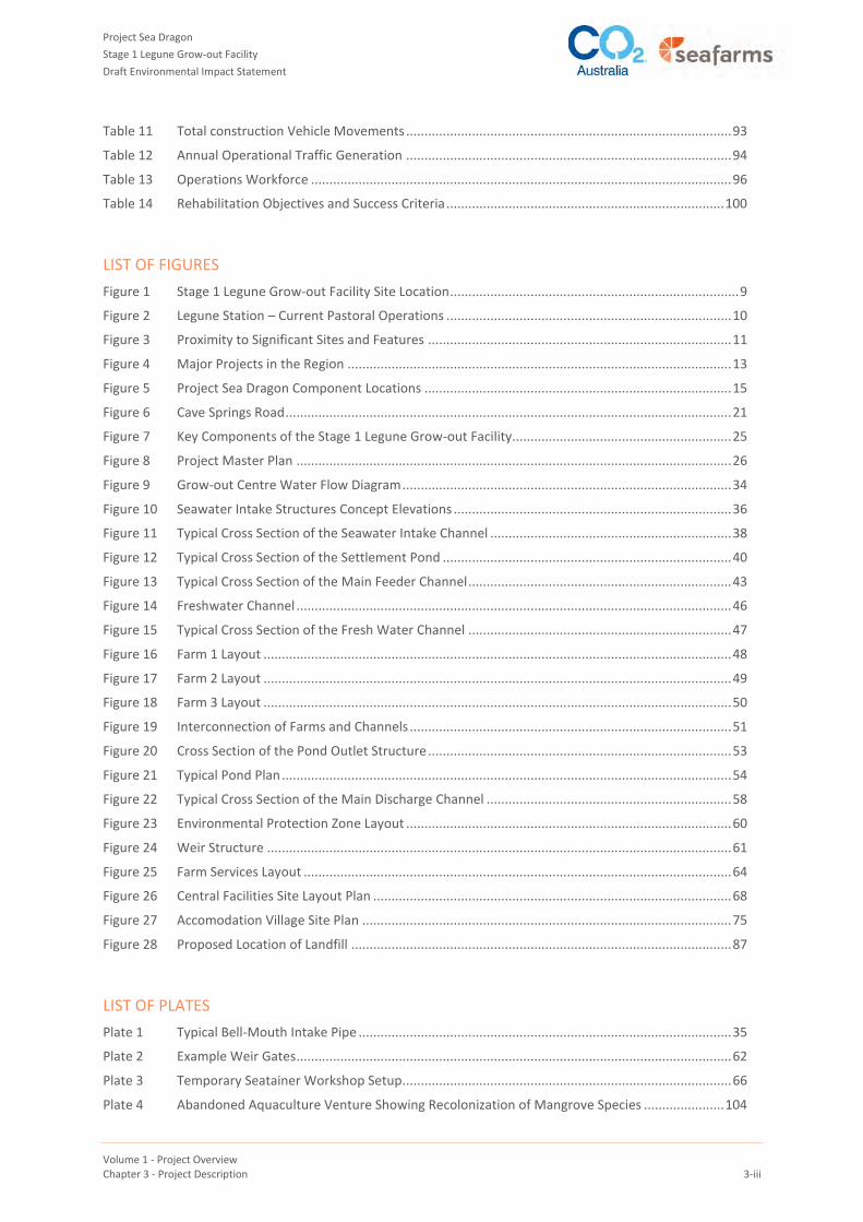
LIST OF FIGURES
Figure 1 Stage 1 Legune Grow-out Facility Site Location ............................................................................... 9
Figure 2 Legune Station – Current Pastoral Operations .............................................................................. 10
Figure 3 Proximity to Significant Sites and Features ................................................................................... 11
Figure 4 Major Projects in the Region ......................................................................................................... 13
Figure 5 Project Sea Dragon Component Locations .................................................................................... 15
Figure 6 Cave Springs Road .......................................................................................................................... 21
Figure 7 Key Components of the Stage 1 Legune Grow-out Facility............................................................ 25
Figure 8 Project Master Plan ....................................................................................................................... 26
Figure 9 Grow-out Centre Water Flow Diagram .......................................................................................... 34
Figure 10 Seawater Intake Structures Concept Elevations ............................................................................ 36
Figure 11 Typical Cross Section of the Seawater Intake Channel .................................................................. 38
Figure 12 Typical Cross Section of the Settlement Pond ............................................................................... 40
Figure 13 Typical Cross Section of the Main Feeder Channel ........................................................................ 43
Figure 14 Freshwater Channel ....................................................................................................................... 46
Figure 15 Typical Cross Section of the Fresh Water Channel ........................................................................ 47
Figure 16 Farm 1 Layout ................................................................................................................................ 48
Figure 17 Farm 2 Layout ................................................................................................................................ 49
Figure 18 Farm 3 Layout ................................................................................................................................ 50
Figure 19 Interconnection of Farms and Channels ........................................................................................ 51
Figure 20 Cross Section of the Pond Outlet Structure ................................................................................... 53
Figure 21 Typical Pond Plan ........................................................................................................................... 54
Figure 22 Typical Cross Section of the Main Discharge Channel ................................................................... 58
Figure 23 Environmental Protection Zone Layout ......................................................................................... 60
Figure 24 Weir Structure ............................................................................................................................... 61
Figure 25 Farm Services Layout ..................................................................................................................... 64
Figure 26 Central Facilities Site Layout Plan .................................................................................................. 68
Figure 27 Accomodation Village Site Plan ..................................................................................................... 75
Figure 28 Proposed Location of Landfill ........................................................................................................ 87
LIST OF PLATES
Plate 1 Typical Bell-Mouth Intake Pipe ...................................................................................................... 35
Plate 2 Example Weir Gates ....................................................................................................................... 62
Plate 3 Temporary Seatainer Workshop Setup.......................................................................................... 66
Plate 4 Abandoned Aquaculture Venture Showing Recolonization of Mangrove Species ...................... 104

Project Sea Dragon
Stage 1 Legune Grow-out Facility
Draft Environmental Impact Statement
Volume 1 - Project Overview Chapter 3 - Project Description 3 -1
1 INTRODUCTION
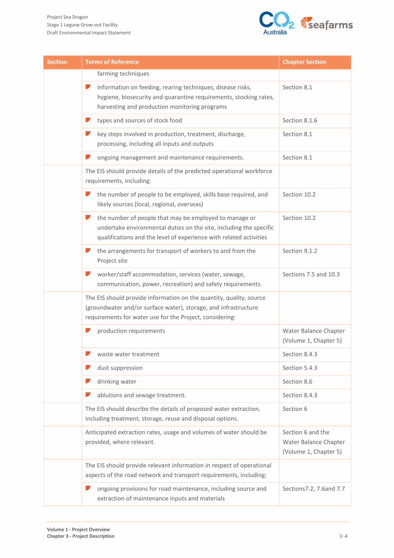
1.1 TERMS OF REFERENCE ADDRESSED IN THIS CHAPTER
This chapter provides an overview of the construction, operation and decommissioning phases of the Project
Sea Dragon Stage 1 Legune Grow-out Facility (the Project).
Table 1 summarises the requirements from the Terms of Reference for the Preparation of an Environmental
Impact Statement (ToR) for the Project and where they have been addressed in this chapter.
TABLE 1 TERMS OF REFERENCE
Section Terms of Reference Chapter Section
2.1 General Information
The Environmental Impact Statement (EIS) should identify all the
processes and activities intended for the Project and associated
ancillary activities, during the life of the Project. The EIS should
provide a brief background and context to the Project, including:
the title of the Project Section 2.1
the full name, contact details and postal address of the Proponent Section 2.2
the current status of the Project Section 2.5
the location of the Project in the region and its proximity to: Section 2.6
landmark features
sites of cultural significance
sites of social significance
regional community centres
areas on the National Reserve System
sensitive environments, such as major waterways,
significant groundwater resources, significant natural
features and conservation reserves
Section 2.6.1
the location of all infrastructure (both existing and proposed)
relating to any aspect of the construction, operation and
decommissioning /rehabilitation of the action
Figure 8
the background to the development of the Project, including
discussion of previous or other environmental impact assessment
Project Alternatives
Chapter (Volume 1,
Chapter 4)
how the Project relates to any other proposals or actions, of
which the Proponent should reasonably be aware, that have been
or are being taken, or that have been approved in the region (e.g.
Ord Stage 3, expansion of the Keep River National Park)
Section 2.9
lease requirements, land tenure, acquisition requirements
(permits, rezoning and Native Title (e.g. Legune Area Claim No.
Section 2.7

Project Sea Dragon
Stage 1 Legune Grow-out Facility
Draft Environmental Impact Statement
Volume 1 - Project Overview Chapter 3 - Project Description 3 -2
Section Terms of Reference Chapter Section
188)), and the
tenures under which the Project would be held, including details
of relevant legislative processes required to grant proposed
tenure
Section 2.7
identification of areas proposed for future expansion, or any
other potential future activities being planned
Section 2.8.6
National, State and/or Territory standards, codes of practice and
guidelines relevant to the Project.
Approvals, Conditions
and Agreements
Chapter (Volume 1,
Chapter 6)
2.2 Project Components
The EIS should provide an overview of the construction, operation and
decommissioning/closure phases of the proposed action and describe
relevant activities at each phase. Aspects to be covered include, but
are not limited to:
a detailed schedule or timetable of all relevant aspects of the
Project
Section 3
delineation of the Project footprint using detailed maps and
diagrams. Include:
all areas to be cleared, disturbed or temporarily utilised
(such as laydown areas) during construction
the major components of the Project:
production ponds
settlement/recycling ponds and basins
water storages (dams and tanks)
intake and discharge channels/canals/pipelines
and pumps
water supply channels/canals/pipelines and
pumps
sewerage
waste management infrastructure
buildings (including accommodation village),
roads and hardstand areas
power generation plant and ancillary fuel
storage
service corridors
environmental protection zone and constructed
wetlands
communication infrastructure
quarry/borrow pits
barge landing.
Figure 8

Project Sea Dragon
Stage 1 Legune Grow-out Facility
Draft Environmental Impact Statement
Volume 1 - Project Overview Chapter 3 - Project Description 3 -3
Section Terms of Reference Chapter Section
2.2.1 Construction Phase
The EIS should describe the preferred methods and processes during
construction, including:
plant and machinery required Section 5
construction materials required, e.g. major types, quantities,
qualities and sources
Section 5
traffic management requirements, including:
operating times and scheduling
vehicle types, numbers and frequency
the estimated volumes, tonnage, composition, origin,
destination and proposed routes of traffic generated by
the proposal
hazardous or dangerous material that may be
transported
traffic flow management, including site access and
signage.
Section 9.1.1 and
Traffic and Transport
Chapter (Volume 3,
Chapter 4)
The EIS should provide design and engineering details of all ponds and
water storage structures including:
dimensions
construction materials, including liners
alignment
batter slope design
water intake
outflows and overflows
pumping and transfer systems.
Section 6
Preferred design criteria for major components of the facility should
be described including the limitations imposed by site characteristics,
and consideration of climate change and extreme weather events in
the design.
Sections and 7
Methods for the storage, handling, containment and emergency
management of chemicals and other hazardous substances (including
fuel) should be described.
Section 8.5
Outline the construction workforce requirements, including expected
numbers, sources, accommodation requirements, services required
and transport arrangements.
Section 10.1
2.2.2 Production Process and Operation
The EIS should describe all aspects of the production cycle, including:
species to be cultured, sources of juveniles/brood stock and Section 8.1
Project Sea Dragon
Stage 1 Legune Grow-out Facility
Draft Environmental Impact Statement
Volume 1 - Project Overview Chapter 3 - Project Description 3 -4
Section Terms of Reference Chapter Section
farming techniques
information on feeding, rearing techniques, disease risks,
hygiene, biosecurity and quarantine requirements, stocking rates,
harvesting and production monitoring programs
Section 8.1
types and sources of stock food Section 8.1.6
key steps involved in production, treatment, discharge,
processing, including all inputs and outputs
Section 8.1
ongoing management and maintenance requirements. Section 8.1
The EIS should provide details of the predicted operational workforce
requirements, including:
the number of people to be employed, skills base required, and
likely sources (local, regional, overseas)
Section 10.2
the number of people that may be employed to manage or
undertake environmental duties on the site, including the specific
qualifications and the level of experience with related activities
Section 10.2
the arrangements for transport of workers to and from the
Project site
Section 9.1.2
worker/staff accommodation, services (water, sewage,
communication, power, recreation) and safety requirements.
Sections 7.5 and 10.3
The EIS should provide information on the quantity, quality, source
(groundwater and/or surface water), storage, and infrastructure
requirements for water use for the Project, considering:
production requirements Water Balance Chapter
(Volume 1, Chapter 5)
waste water treatment Section 8.4.3
dust suppression Section 5.4.3
drinking water Section 8.6
ablutions and sewage treatment. Section 8.4.3
The EIS should describe the details of proposed water extraction,
including treatment, storage, reuse and disposal options.
Section 6
Anticipated extraction rates, usage and volumes of water should be
provided, where relevant.
Section 6 and the
Water Balance Chapter
(Volume 1, Chapter 5)
The EIS should provide relevant information in respect of operational
aspects of the road network and transport requirements, including:
ongoing provisions for road maintenance, including source and
extraction of maintenance inputs and materials
Sections7.2, 7.6and 7.7

Project Sea Dragon
Stage 1 Legune Grow-out Facility
Draft Environmental Impact Statement
Volume 1 - Project Overview Chapter 3 - Project Description 3 -5
Section Terms of Reference Chapter Section
type, size and number of vehicles required Section 9.1.2 and
Traffic and Transport
Chapter (Volume 3,
Chapter 4)
estimated frequency and times of Project vehicle use on public
infrastructure
Section 9.1.2 and
Traffic and Transport
Chapter (Volume 3,
Chapter 4)
routes for operational transport Section 9.1.2 and
Traffic and Transport
Chapter (Volume 3,
Chapter 4)
expected fuel, oil and tyre usage (and storage and disposal). Section 8.4.1
2.2.3 Decommissioning and Rehabilitation
The EIS should discuss the expected life of the Project and plan for
decommissioning and closure, including unexpected closure. At a
minimum, the EIS should:
identify options for decommissioning of all components of the
Project and rehabilitation of the site
Section 11.2
discuss relevant aspects of closure planning and decommissioning
such as waste management, pollution control, land stabilisation,
erosion and sediment control, revegetation and avoidance of
breeding sites for biting insects
Section 11.3.4
propose environmental objectives and completion criteria against
which the progress of decommissioning and rehabilitation can be
measured.
Section 11.3.1

Project Sea Dragon
Stage 1 Legune Grow-out Facility
Draft Environmental Impact Statement
Volume 1 - Project Overview Chapter 3 - Project Description 3 -6
2 GENERAL INFORMATION
2.1 PROJECT TITLE
This draft Environmental Impact Statement (EIS) is for construction and operation of the “Project Sea Dragon
Stage 1 Legune Grow-out Facility” (herein referred to as the Project).
2.2 PROJECT PROPONENT
The project proponent is Project Sea Dragon Pty Ltd (PSD), a wholly owned subsidiary of Seafarms Group
Limited (Seafarms). Seafarms is an ASX (ASX:SFG) listed company holding separate subsidiary companies each
operating in emerging, non-conventional commodities areas - aquaculture, carbon and environmental offsets.
The companies are Seafarms Operations Limited, Seafarms Queensland Pty Ltd and CO2 Australia Limited.
Project Sea Dragon Pty Ltd details are outlined in Table 2. Details for the primary contact person for this
application are provided in Table 3.
Seafarms is an Australian agri-food company which operates, builds and invests in sustainable aquaculture
production platforms producing high-quality seafood. Seafarms is currently Australia’s largest producer of
farmed prawns – growing, processing and distributing the well-known Crystal Bay Prawns® premium brand.
Seafarms has existing operations in Innisfail, Cardwell and Ingham, Queensland, and is a major supplier of
prawns to Coles and Woolworths on the East Coast. The company is Australia’s largest prawn aquaculture
enterprise.
TABLE 2 PROJECT SEA DRAGON PTY LTD DETAILS
Required Information Details
ACN 604 936 192
Street Address Level 11, 225 St Georges Terrace, Perth WA 6000 Australia
Postal Address P.O. Box 7312 Cloisters Square, Perth WA 6850 Australia
Phone +61 8 9321 4117
Fax +61 8 9321 4411
Website http://seafarmsgroup.com.au/project-sea-dragon/
TABLE 3 PRIMARY CONTACT DETAILS
Required Information Details
Name Chris Mitchell
Title Executive Director – Seafarms Group Limited
Postal Address Unit 6 Ground Floor 31-47 Joseph St Blackburn North VIC 3130
Phone 03 9928 5111
Fax 03 9928 5199
Email [email protected]

Project Sea Dragon
Stage 1 Legune Grow-out Facility
Draft Environmental Impact Statement
Volume 1 - Project Overview Chapter 3 - Project Description 3 -7
2.3 ABOUT SEAFARMS
Seafarms is currently the largest Australian producer of farmed prawns – growing, processing and distributing
the well-known Crystal Bay Prawns® premium brand. Seafarms has 148 ponds covering 160 hectares, across
three locations throughout north Queensland. Seafarms is committed to sustainability and believe that farmed
seafood is the most sustainable way to provide seafood to the world. Crystal Bay Prawns are produced using
environmentally sustainable culture processes, state of the art processing facilities and support services.
Seafarms believes that protection of the environment is a primary corporate responsibility. Therefore, all the
Seafarms business activities reflect these beliefs and Seafarms strive to constantly:
adopt best management practices to conduct operations in an environmentally responsible manner
implement sound environmental management practices to minimise the impacts due to our business
operations
comply with all relevant environmental regulations
minimise resource consumption and waste generation by efficient use of resources
protect all natural ecosystems in proximity to our operations
conduct necessary programmes to enhance environmental awareness among our employees.
Seafarms and its subsidiary companies have a strong record of environmental management across a diverse
portfolio of aquaculture, carbon and environmental projects, and have implemented an Environmental
Management System for Project Sea Dragon (refer to Volume 4, Chapter 2).
2.4 ABOUT PROJECT SEA DRAGON
Project Sea Dragon is an integrated, world class prawn aquaculture project, recognising that the demands on
wild caught fisheries cannot be sustained without supplementary resources from other means. The project has
been developed to be a low environmental impact aquaculture project - low cost, long term, sustainable
operation, with strong biosecurity and environmental controls, and utilising best practice marine and
aquaculture science.
Project Sea Dragon is committed to sustainable operations, continual environmental improvement and the
prevention of land, water and air pollution.
Our aim is to be recognised as a world leader in sustainable aquaculture by:
Complying with all relevant legislation, regulations and standards relating to the Project
Minimising pollution and managing potential environmental impacts resulting from our activities
Continually improving our environmental management practices through training, management review,
research and consultation with employees and the community
Integrating environmental considerations into planning and operations
Promoting the efficient use, reuse and recycling of resources
Educating employees and contractors to support our environmental goals and objectives
Monitoring and reporting our progress on environmental performance to all relevant external bodies and
our employees.

Project Sea Dragon
Stage 1 Legune Grow-out Facility
Draft Environmental Impact Statement
Volume 1 - Project Overview Chapter 3 - Project Description 3 -8
2.5 PROJECT STATUS
Project Sea Dragon has completed the Feasibility Study for the Project and has entered into the Due Diligence
phase leading to Financial Investment Decision. The company also has a current Access and Options Agreement
for Legune Station, which will allow the acquisition of the pastoral lease, subject to obtaining the necessary
statutory approvals.
2.6 LOCATION
The Project is proposed to be located at Legune Station in the Northern Territory (NT). Legune Station
comprises NT Portion 798 and Portion 3222 in the Victoria River District. Legune Station is currently used for
cattle grazing under a perpetual pastoral lease. The pastoral lease has an area of approximately 178,800 ha and
is located near the western border of the Northern Territory. Road access to the site is from Western Australia
(WA). The nearest town, including police, fire and emergency services is Kununurra (106 km by road) in WA and
the nearest port is Wyndham, also in WA (212 km by road). The project is located wholly within the NT Victoria
Daly Local Government Area, and the nearest NT town is Timber Creek, although access to Timber Creek is via
Kununurra. The location of the site is shown in Figure 1.
Legune Station has historically been used for cattle grazing under a pastoral lease and was originally an
outstation of the Victoria River Downs Station. The improvements on the land include dwellings and farm
sheds, cattle yards, stock watering points, paddocks and fencing, and a 35,000 megalitre freshwater dam
constructed on Forsyth Creek that is used for irrigation of pasture during the dry season. Current pastoral
operations are illustrated in Figure 2.
The Grow-out ponds comprise the major part of the Project Area - these are located above RL (reduced level)
4.5 m AHD (Australian Height Datum), utilising the grassed areas currently used for cattle operations. The
Grow-out ponds require flat topography and will be constructed, in such a way as to provide flood, storm surge
and sea level rise immunity, and to avoid the coastal plain (i.e. the area subject to regular tidal influence -
nominally between RL 4.5 m and 5.0 m AHD) containing mangrove communities and greater incidence of
shallow potential acid-sulfate soils (PASS). Investigation of the vegetation present confirms that the areas
proposed for development are not subject to a regular tidal inundation.
2.6.1 Proximity to Significant Sites and Features
Legune Station is bordered by the Keep River to the west, and Victoria River to the east, as shown in Figure 3.
The Stage 1 Legune Grow-out Facility Project footprint is situated within the Legune Coastal Floodplain Site of
Conservation Significance (see Figure 3).
The Legune Wetlands are also situated on Legune Station, and are recognised as a Nationally Important
Wetland. The proposed services corridor and one of the proposed roads intersect the Legune Wetlands (see
Figure 3).
Areas of Indigenous cultural significance occur on Legune Station, however, in informal consultation with the
Traditional Owners and using available information with Aboriginal Areas Protection Authority (AAPA), the
project has been designed to avoid these areas. A Clearance Certificate to be issued by AAPA will further inform
the detailed design.
The closest National Park is the Keep River National Park located along the NT/WA border around 80 km to the
south-west of the proposed Project footprint. A proposed extension to the Keep River National Park would
extend the National Park to around 17 km south of the proposed Central Facilities and Accommodation Village.
There are no anticipated impacts to the Keep River National Park or its proposed extension (see Figure 3).

Project Sea Dragon
Stage 1 Legune Grow-out Facility
Draft Environmental Impact Statement
Volume 1 - Project Overview Chapter 3 - Project Description 3 -9
FIGURE 1 STAGE 1 LEGUNE GROW-OUT FACILITY SITE LOCATION

Project Sea Dragon
Stage 1 Legune Grow-out Facility
Draft Environmental Impact Statement
Volume 1 - Project Overview Chapter 3 - Project Description 3 -10
FIGURE 2 LEGUNE STATION – CURRENT PASTORAL OPERATIONS

Project Sea Dragon
Stage 1 Legune Grow-out Facility
Draft Environmental Impact Statement
Volume 1 - Project Overview Chapter 3 - Project Description 3 -11
FIGURE 3 PROXIMITY TO SIGNIFICANT SITES AND FEATURES

Project Sea Dragon
Stage 1 Legune Grow-out Facility
Draft Environmental Impact Statement
Volume 1 - Project Overview Chapter 3 - Project Description 3 -12
2.7 TENURE
2.7.1 Perpetual Pastoral Lease
NT Portions 798 and 3222 are currently subject to Perpetual Pastoral Lease 1062 (refer to Figure 2). The lease
owner is Legune Land Pty Ltd and the commencement date of the lease is 1 April 1993. The lease is subject to
the conditions and reservations set out in sections 38 and 39 of the Pastoral Land Act.
In accordance with the requirements of the Pastoral Land Act the proponent will make an application for a non-
pastoral use permit which will allow the use of part of the Legune Station pastoral lease for a non-pastoral
purpose (i.e. aquaculture).
2.7.2 Native Title
Native title exists on parts of NT Portions 798 and 3222 of Legune Station (Determination Name: Simon v
Northern Territory of Australia, 31 May 2011). The recognised Native Title holders are members of the
Gajirrabung1 language group which comprise members of the Gajirrabung Wadanybang, Gajirrabung Gurrbijim
and Gajirrabung Jarrajarrany2 groups. The native title determination gives the Native Title holders rights to:
maintain and protect sites and places on those areas that are of significance under their traditional laws
and customs
engage in cultural activities on land, including participating in cultural practices relating to birth and death
conducting ceremonies and meetings
teaching the physical and spiritual attributes of sites and places on areas of significance under Aboriginal
traditional laws and customs.
The proponent is currently pursuing the development of an Indigenous Land Use Agreement (ILUA) for the
Project Area with the Native Title holders through the Northern Land Council.
2.7.3 Mining Titles
As shown on Figure 4, mining titles located within the vicinity of the proposed Project Area include:
exploration permit (EP) 126 for petroleum and pipeline - granted on 15 June 2011 with an expiry date of 14
June 2016 (but currently under a suspension extension, due to lapse on 14 December 2016). It is jointly
held by Territory Oil and Gas Pty Ltd (45%) and Beach Petroleum Pty Ltd (55%), and
exploration licence (EL) 24395 and EL 25646 for minerals - EL 24395 was granted on 16 August 2005 and is
due to expire on 15 August 2017, and EL 25646 was granted on 23 August 2007 and is due to expire on 22
August 2017. Both are held by Tennant Creek Gold (NT) Pty Ltd
1 The Gajirrabung language and people are also referred to as “Gajerrong” and this name was used in the Federal Court’s determination of Native Title holders over the Legune pastoral lease. 2 Jarrajarrany is spelt “Djarradjarany” in the determination of Native Title. The draft EIS has adopted the orthography recommended by the Native Title Representative Body.

Project Sea Dragon
Stage 1 Legune Grow-out Facility
Draft Environmental Impact Statement
Volume 1 - Project Overview Chapter 3 - Project Description 3 -13
FIGURE 4 MAJOR PROJECTS IN THE REGION

Project Sea Dragon
Stage 1 Legune Grow-out Facility
Draft Environmental Impact Statement
Volume 1 - Project Overview Chapter 3 - Project Description 3 -14
2.8 RELATIONSHIP TO LARGER PROJECT COMPONENTS
2.8.1 Stage 1 Legune Grow Out Facility
The Stage 1 Legune Grow-out Facility is part of a larger project including other ancillary aspects of Stage 1 to be
located in Darwin, Exmouth, Kununurra and Wyndham; and future proposed stages to reach full scale
operations. However, these aspects of the larger project are not part of this EIS for geographical and
operational (timing) reasons. These facilities will be subject to separate environmental approval processes as
required, and development application approvals as required.
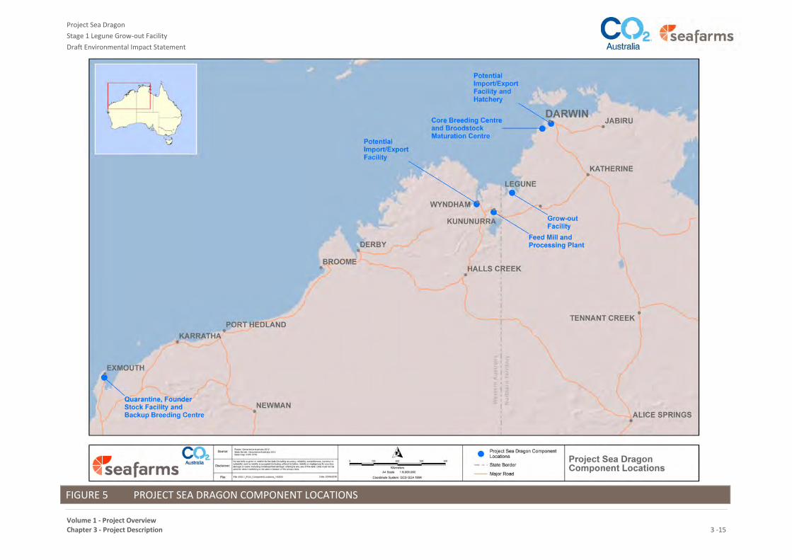
Stage 1 will be located over several sites as described below, and shown in Figure 5:
Grow-out Facility – proposed to be located at Legune Station (NT) – the subject of this EIS.
Quarantine, Founder Stock Facility and Back-up Breeding Centre –located at Exmouth (WA).
Breeding Program - proposed to be located at Point Ceylon at Bynoe Harbour (NT).
Hatchery Site – proposed to be located in the Darwin (NT) environs.
Processing Plant – proposed to be located near Kununurra in Western Australia (WA), and
Export Facilities – utilising existing port infrastructure by 3rd parties at either or both Wyndham and
Darwin.
Stage 1 will produce nominally 14,000 tonnes of prawns per annum. This estimate is based upon production
after several years of operation, taking account of opportunities to optimise animal husbandry within that
environment and operating system and resulting from improved growth rates from domestication and
selective breeding.
Project Sea Dragon
Stage 1 Legune Grow-out Facility
Draft Environmental Impact Statement
Volume 1 - Project Overview Chapter 3 - Project Description 3 -15
FIGURE 5 PROJECT SEA DRAGON COMPONENT LOCATIONS

Project Sea Dragon
Stage 1 Legune Grow-out Facility
Draft Environmental Impact Statement
Volume 1 - Project Overview Chapter 3 - Project Description 3-16
2.8.2 Quarantine, Founder Stock Facility (FSC) and Back-up Breeding Centre (BBC)
Disease can be a major operational risk for all forms of aquaculture around the world. Disease, in both the
acute and chronic forms, can seriously impact on profitability and sustainability at the farm and industry level.
Critical to the success of Project Sea Dragon's operations will be biosecurity systems in place at a number of
levels - national, regional and operational.
The first step in this process is to develop a population of 'founder animals', who will be screened for disease
and bred for three generations to develop prawns that are free of specific disease agents (pathogens).
Establishment of a domesticated population of animals free of specific pathogens (SPF)3, particularly notifiable
diseases, is feasible, provided Project Sea Dragon uses quarantine facilities within a high biosecurity
environment.
Investigations have confirmed that the development of a population of founder animals will require
recruitment from the wild at sustainable levels. To commence the stocking of the Founder Stock Centre, there
will be between two and four collections of wild catch taken per annum, with the aim of collecting up to 150
pairs of animals in each collection (i.e. the total wild catch per annum will be up to 1200 individuals only). The
catch will be conducted using licenced operators. As the founder population is developed through a number of
generations, the project will reduce requirements for wild caught individuals. Ultimately there will be
negligible, if any, wild caught individuals in the population. A thorough investigation of disease status in wild
and domesticated Black Tiger prawn populations has narrowed likely target wild populations to those from the
Northern Territory and Western Australia.
The refurbishment of the company’s existing facility at Exmouth has commenced, to form the Quarantine and
Founder Stock Centre (FSC) to house the wild caught stock and commence the breeding cycle in the timeline
required for the rest of the project. Two generations will be bred, with disease screening at regular intervals in
the life cycle in order to produce Specific Pathogen Free prawns stocks prior to delivery to the Breeding
Program facilities. These specific pathogen free prawns will then be delivered to the Core Breeding Centre
(CBC).
Once a domesticated Black Tiger prawn population is achieved, the Exmouth facility will continue to operate as
the Back-up Breeding Centre (BBC). This back-up facility is required to retain, in a secure environment, a
population of domesticated and improved stock as a risk-mitigation measure against the catastrophic loss of
animals at the Core Breeding Centre (CBC - refer Section 2.8.3.1). The BBC will be used for the rearing of
selected individuals (representative genetic stock) sourced from the CBC. The BBC will therefore hold a small
number of individuals from each family to enable rapid replacement of genetic stock in the event of losses at
the CBC.
This facility will be fully biosecure and managed in accordance with the requirements of the PSD Biosecurity
Manual, and meeting national and international biosecurity standards.
2.8.3 Breeding Program
Stage 1 of Project Sea Dragon includes the Core Breeding Centre (CBC) and Broodstock Maturation Centre
(BMC).
3 SPF refers to a domesticated and selectively breed population of animals that have been screened for a suite of known pathogens. The specific list of pathogens that prawns for the Project will be screened for will be guided by the OIE World Organisation for Animal Health list of notifiable terrestrial and aquatic animal diseases.

Project Sea Dragon
Stage 1 Legune Grow-out Facility
Draft Environmental Impact Statement
Volume 1 - Project Overview Chapter 3 - Project Description 3-17
2.8.3.1 Core Breeding Centre (CBC)
The CBC will be located to the east of Point Ceylon near Toss Point (refer to Figure 5) and will be used for the
genetic development, production and selection of high performing Specific Pathogen Free prawns. The prawns
for the CBC will be sourced from the Founder Stock Facility in Exmouth. At the CBC, families of prawns will be
raised to avoid unmanaged cross-breeding, and to maintain genetic lineages. The top individual performers
within the top families will be used to supply the Broodstock Maturation Centre and produce commercial
broodstock. At full scale production, the CBC will have capacity for up to 400 families4 of unrelated genetic
signatures. The CBC will be fully biosecure and managed in accordance with the requirements of the PSD
Biosecurity Manual.
The CBC will comprise between 16 membrane skinned buildings containing hatchery operations, tanks for
rearing prawn stock and external covered grow-out raceways. At full scale the CBC will cover an area of
approximately 10 ha.
2.8.3.2 Broodstock Maturation Centre (BMC)
The BMC will be used to grow and mature the selected post larvae (PLs) and larger broodstock supplied from
the Core Breeding Centre. The BMC will be located on high ground to the south of Point Ceylon. The young
broodstock entering the BMC from the Core Breeding Centre will be Specific Pathogen Free, in good health and
brought up to a suitable size and condition for breeding. The BMC will be responsible for the production of
commercial numbers of spawners and their mates for the commercial hatchery, which is to be located within
the Darwin environs. The BMC will be fully biosecure and managed in accordance with the requirements of the
PSD Biosecurity Manual.
The BMC will comprise between 32 membrane skinned buildings. The majority of the activities undertaken at
the BMC will be contained in buildings, tanks and enclosures within each module. At full scale the BMC will
cover an area of approximately 15 ha.
2.8.3.3 Commercial Hatchery
To supply the Stage 1 Legune Grow-out Facility, the Project Sea Dragon hatchery (the Hatchery) will require
approximately 750 broodstock prawns per week, from the Broodstock Maturation Centre. These broodstock
will be high health, Specific Pathogen Free, of superior pedigree, on-grown to maturity and in breeding
condition.
At full scale production the hatchery will produce up to 100 million post-larvae (PLs) per week based on a 12
month per annum production cycle, running continuously with rolling dry-outs.
The Hatchery is assumed to be built in the Darwin environs, at a separate location to the other Breeding
Program facilities.
2.8.4 Processing Plant
The Processing Plant will be sited on an approved parcel of Government land in Kununurra. The company has
applied to the WA Government to occupy Part Lot 203 on Plan 27929. As mentioned earlier, the processing
plant is subject to separate assessment and approval by the WA Government.
At the processing plant prawns will be cleaned, graded, packed, frozen and palletised for transport in
refrigerated containers to port.
4 A family is a related group of animals with a traceable and controlled pedigree, and degree of relatedness.
Project Sea Dragon
Stage 1 Legune Grow-out Facility
Draft Environmental Impact Statement
Volume 1 - Project Overview Chapter 3 - Project Description 3-18
Harvested prawns will be transported to the processing plant in ice slurry. A key parameter for processing is
being able to transport harvested prawns to the processing plant within a short time, typically 1 to 2 hours, to
ensure that processing is achieved within 4-6 hours. A detailed simulation model covers the harvesting
activities from the Stage 1 Legune Grow-out Facility to Kununurra to ensure that the transport and product
handling system can cope, without unacceptable delays and loss of product.
Project Sea Dragon would benefit from domiciling as much of the workforce at Kununurra as possible, in the
established town. This will allow a ‘normalised’ outcome for residential living, thus minimising social impacts
associated with temporary domiciling of workers at work sites. There may be some requirement for the
company to provide bussing for some of the workforce from the town to the processing plant site.
For Stage 1 the processing plant will be sized to process up to 80 tonnes of prawns per day.
2.8.5 Port Facilities
There will be no requirement to construct port facilities for Stage 1 of the Project.
A comprehensive transport and logistics study was commissioned by PSD, and undertaken by Jebsens, a
shipping company with transport links and Australian coastal shipping operations. The study examined the
existing ports of Darwin, Wyndham, Fremantle and Adelaide for the transport and shipping of feed, fuel and
product, and considered road transport and the Ghan railway options, where relevant, to determine the likely
port options.
The findings of that study were that, for Stage 1, there is sufficient existing capacity in Wyndham port to handle
the combined quantities of feed imports, fuel imports and product exports. Therefore, the Project will use
existing facilities at Wyndham port and road transport to and from the site.
2.8.6 Future Stages
Project Sea Dragon is a large-scale, integrated, land-based aquaculture project in northern Australia with the
potential at final stage to produce >100,000 tonnes per annum of Black Tiger Prawns generating an export
revenue of AUD $1.6 B per annum. However the project will be developed progressively over several stages
and it is intended to use Stage 1 of the project to test and refine process and environmental performance to
inform future stages, as well as seek solutions to future water requirements.
There are a number of benefits to staging the development of the project including the learnings obtained from
each incremental stage. By committing to Stage 1 (1,080 ha of ponds) Project Sea Dragon Pty Ltd will be in a
position to monitor impacts and collect vital data to shape the design and implementation of subsequent
stages of expansion. Therefore, the expansion of Project Sea Dragon to Full Scale will be determined by the
company as Stage 1 progresses and is subject to:
the success of Stage 1 operations, and the learnings from Stage 1, including environmental management
further statutory approvals
project cash-flow
capital funding.
At Full Scale the project will include facilities at Legune and across the Darwin, Kununurra, Wyndham and
Exmouth environs as described below.
At Legune:
27 farms with a total productive area of 9,720 ha

Project Sea Dragon
Stage 1 Legune Grow-out Facility
Draft Environmental Impact Statement
Volume 1 - Project Overview Chapter 3 - Project Description 3-19
internal farm recycling ponds of 2,916 ha
10 seawater intake pumps, distributed in 2 seawater intake structures (Forsyth Creek and Sandy Creek)
intake settlement basins
Main Feeder Channels (MFC) for the delivery of seawater
an expanded environmental protection zone and constructed marine wetlands
an additional dam for freshwater storage and added delivery channel
Main Discharge Channels (MDC)
power generation plant (hybrid) and switchyard to meet peak demand of 90 MW at the Grow-out Facility
Gas storage infrastructure for Full Scale power generation requirements, or alternatively a local gas
wellfield
diesel storage for all fleet vehicles
an expanded central village at Legune, and distributed on-farm accommodation
Near Darwin:
a Hatchery able to supply up to 100 million post larvae (PL's) per week
a Core Breeding Centre
a Broodstock Maturation Centre
At Kununurra:
a Feed Mill with total capacity of 200,000 tonnes per year
a processing plant with a capacity of 400 tonnes per day
use of an existing village for accommodating non-local workforce, for a limited start-up period
a power plant to supply the processing plant and Feed Mill
township accommodation, with an emphasis on residential housing integrated with the existing
community
At Wyndham:
use of an existing container park for refrigerated reefer containers
use of existing bulk storage sheds for WA grain and imported ingredients for prawn feed
use of an existing wharf and ship loading/unloading equipment
At Exmouth: Upgrade of an existing aquaculture facility to provide:
Initial Quarantine and Founder Stock Centre
a Backup Breeding Centre

Project Sea Dragon
Stage 1 Legune Grow-out Facility
Draft Environmental Impact Statement
Volume 1 - Project Overview Chapter 3 - Project Description 3-20
2.9 RELATIONSHIP TO OTHER PROJECTS IN THE REGION
The proponent is aware of a number of other projects that have been approved within, or are proposed for,
the region. The other major projects in the region are shown on Figure 4. However, with the exception of the
Processing Plant and the Port Facilities (to be located in Kununurra and Wyndham, respectively), and road
infrastructure between Kununurra and the boundary of Legune Station to be provided by the WA and NT
governments the project does not impact upon, relate to, or depend upon, any other project in the region with
the exception of:
Legune Pastoral Operations
Cave Springs Road upgrade
Manbarrum Zinc-Lead-Silver Project (TNG Limited)
Cullen -1 (Beach Energy)
2.9.1 Legune Pastoral Operations
Legune Station is currently managed as a large-scale pastoral operation, carrying up to 30,000 head of cattle.
An application will be made under the Pastoral Land Act for a non-pastoral use permit to use parts of the lease
for other activities to improve the economic viability of the pastoral operations. This permit will allow the use
of part of the Legune Station pastoral lease for a non-pastoral purpose (i.e. aquaculture).
The existing pastoral operations on Legune station will continue during the construction and operation of all
stages of the Project.
Stage 1 of Project Sea Dragon will remove around 3,239 ha areas of estuarine-deltaic plain (i.e. the fertile
floodplain), which comprises around 50,000 ha of the 178, 800 ha pastoral lease, from pastoral activity. In
addition, water from Forsyth Creek Dam will be redirected from pasture irrigation to prawn pond management.
This reallocation of land and water resources will affect the scale of pastoral operations. However, cattle
grazing will still remain in areas external to the Project footprint. The details of how the pastoral and
aquaculture operations will be managed will specified in the Non-Pastoral Use agreement.
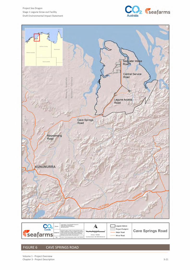
2.9.2 Cave Springs Road Upgrade
Cave Springs Road (also known as Keep River Plains Road) is the public road between the WA border
(connecting to Moonamang Rd, WA) and Legune Station (Figure 6). This section of road is 30.6 km long. The
upgrade of this road to all weather capability is vital to the Project, as it will be required to:
carry product to the Processing Plant north of Kununurra
carry raw materials including feed and energy to Legune
provide the transport link between Kununurra and Legune for personnel, services and consumables.
It is planned that this road will be upgraded by the NT Government as it will become a multi-user piece of
infrastructure. The upgrade of this road is subject to a separate environmental assessment with the NT
Government as the proponent.
It has been proposed that the road will become a 2-lane sealed 7+9 rural road (7 m sealed width; 9 m shoulder-
to-shoulder width) to the NT Department of Transport standard. As such it will have the capacity to handle up
to quad road trains. The bridges will have a capability of handling flood events with an Average Recurrence
Interval (ARI) of once in 50 years, resulting in few delays to the harvest traffic.
The alignment of the road is subject to negotiation with the Traditional Owners and other approval processes
(e.g. AAPA Clearance).
Project Sea Dragon
Stage 1 Legune Grow-out Facility
Draft Environmental Impact Statement
Volume 1 - Project Overview Chapter 3 - Project Description 3-21
FIGURE 6 CAVE SPRINGS ROAD
Project Sea Dragon
Stage 1 Legune Grow-out Facility
Draft Environmental Impact Statement
Volume 1 - Project Overview Chapter 3 - Project Description 3-22
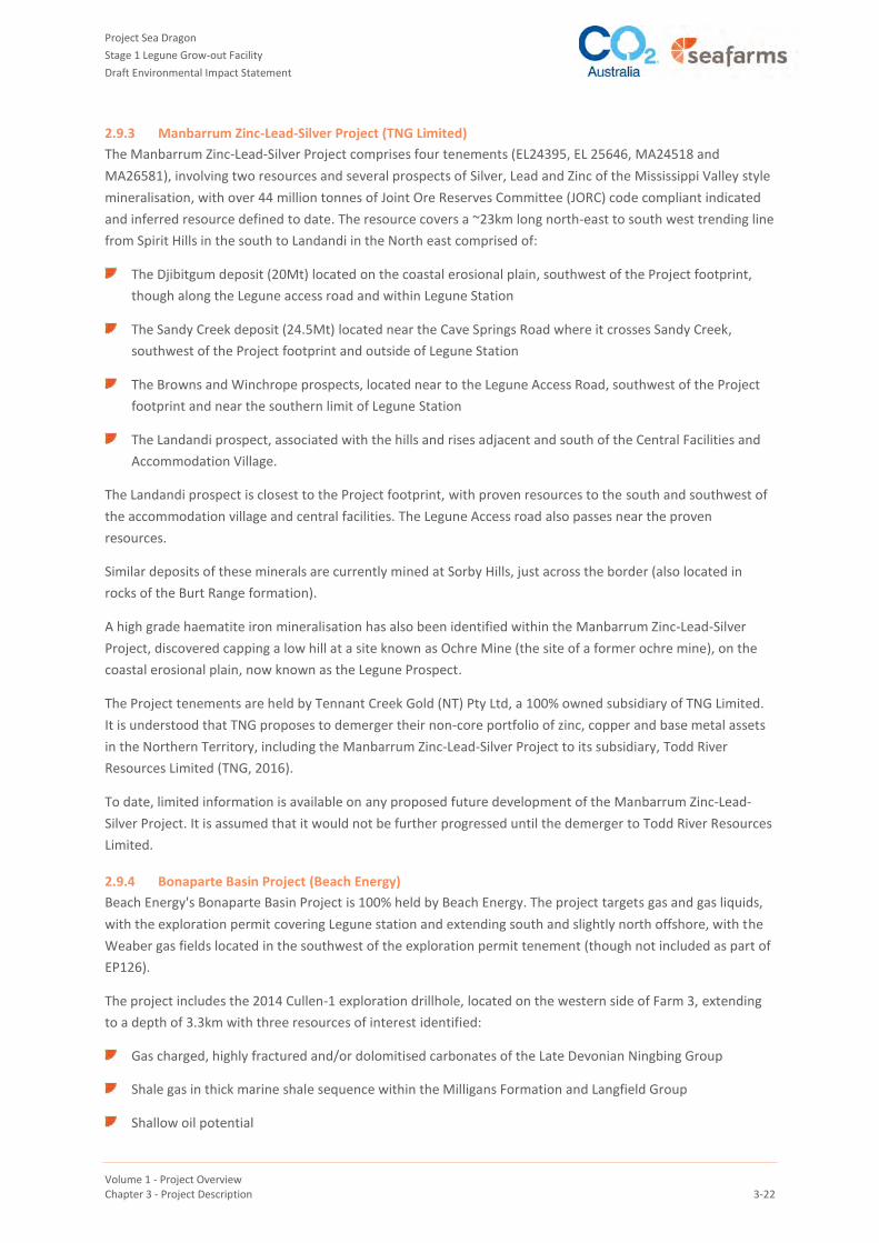
2.9.3 Manbarrum Zinc-Lead-Silver Project (TNG Limited)
The Manbarrum Zinc-Lead-Silver Project comprises four tenements (EL24395, EL 25646, MA24518 and
MA26581), involving two resources and several prospects of Silver, Lead and Zinc of the Mississippi Valley style
mineralisation, with over 44 million tonnes of Joint Ore Reserves Committee (JORC) code compliant indicated
and inferred resource defined to date. The resource covers a ~23km long north-east to south west trending line
from Spirit Hills in the south to Landandi in the North east comprised of:
The Djibitgum deposit (20Mt) located on the coastal erosional plain, southwest of the Project footprint,
though along the Legune access road and within Legune Station
The Sandy Creek deposit (24.5Mt) located near the Cave Springs Road where it crosses Sandy Creek,
southwest of the Project footprint and outside of Legune Station
The Browns and Winchrope prospects, located near to the Legune Access Road, southwest of the Project
footprint and near the southern limit of Legune Station
The Landandi prospect, associated with the hills and rises adjacent and south of the Central Facilities and
Accommodation Village.
The Landandi prospect is closest to the Project footprint, with proven resources to the south and southwest of
the accommodation village and central facilities. The Legune Access road also passes near the proven
resources.
Similar deposits of these minerals are currently mined at Sorby Hills, just across the border (also located in
rocks of the Burt Range formation).
A high grade haematite iron mineralisation has also been identified within the Manbarrum Zinc-Lead-Silver
Project, discovered capping a low hill at a site known as Ochre Mine (the site of a former ochre mine), on the
coastal erosional plain, now known as the Legune Prospect.
The Project tenements are held by Tennant Creek Gold (NT) Pty Ltd, a 100% owned subsidiary of TNG Limited.
It is understood that TNG proposes to demerger their non-core portfolio of zinc, copper and base metal assets
in the Northern Territory, including the Manbarrum Zinc-Lead-Silver Project to its subsidiary, Todd River
Resources Limited (TNG, 2016).
To date, limited information is available on any proposed future development of the Manbarrum Zinc-Lead-
Silver Project. It is assumed that it would not be further progressed until the demerger to Todd River Resources
Limited.
2.9.4 Bonaparte Basin Project (Beach Energy)
Beach Energy's Bonaparte Basin Project is 100% held by Beach Energy. The project targets gas and gas liquids,
with the exploration permit covering Legune station and extending south and slightly north offshore, with the
Weaber gas fields located in the southwest of the exploration permit tenement (though not included as part of
EP126).
The project includes the 2014 Cullen-1 exploration drillhole, located on the western side of Farm 3, extending
to a depth of 3.3km with three resources of interest identified:
Gas charged, highly fractured and/or dolomitised carbonates of the Late Devonian Ningbing Group
Shale gas in thick marine shale sequence within the Milligans Formation and Langfield Group
Shallow oil potential

Project Sea Dragon
Stage 1 Legune Grow-out Facility
Draft Environmental Impact Statement
Volume 1 - Project Overview Chapter 3 - Project Description 3-23
Subject to selecting a suitable farm-in partner, Beach Energy envisages that the next stage of development of
the Bonaparte Basin project will be an extended production test of the conventional fractured carbonate play
discovered in Cullen-1. Beyond that, it envisages future testing of the shale gas interval in Cullen-1. It identifies
possible short term marketing opportunities in local supply, and this includes supply of LNG to the PSD
operations.
The planned exploration and development activities within EP126 will be able to continue unimpeded by the
construction and operation of the project. Access to the Cullen-1 drill hole is available through the proposed
project infrastructure, along with any upgrades Beach Energy (or partners) develop (as needed).

Project Sea Dragon
Stage 1 Legune Grow-out Facility
Draft Environmental Impact Statement
Volume 1 - Project Overview Chapter 3 - Project Description 3-24
3 PROJECT SCHEDULE
As outlined in Table 4, Project construction is scheduled to commence in July 2017. However, commencement
of construction is dependent upon receiving all necessary Project approvals (which are detailed in Volume 1,
Chapter 6 – Approvals, Conditions and Agreements). Additionally, the commencement and duration of
construction will be heavily influenced by wet season constraints and the provision of road infrastructure by
the WA and NT governments outside of the Project footprint.
Assuming no government road upgrades until the dry season of 2017, meaning no significant construction
activity at Legune commencing before April 2017, the key project schedule milestone dates are expected to be
as set out in Table 4. Principal risks to this project schedule include:
delays in receiving all necessary approvals (Environmental, Indigenous, Governmental)
unexpected adverse weather or unexpected longer wet seasons
delays in project financing
delays in the breeding program.
Financial and modelling for the Project has assumed a nominal 25 year operating life. However, there is nothing
in the proposed assets, facilities design, breeding program and operating plan which would prevent the
business from continuing for a significantly longer period. In fact, the business is intended to operate for
decades - the nominal 25 year operating life was selected to align approximately with the initial period of a
Non-Pastoral Use Permit and to enable an economic assessment to be undertaken within a defined period.
TABLE 4 PROJECT SCHEDULE - SUMMARY
Activity Milestone
Project sanction (all approvals received) March 2017
Site establishment, laydown areas, access roads etc. April 2017
Project construction July 2017 - November 2019
Commissioning, testing, pond filling and preparation October 2019
1st post-larvae delivered to farms December 2019
Project Sea Dragon
Stage 1 Legune Grow-out Facility
Draft Environmental Impact Statement
Volume 1 - Project Overview Chapter 3 - Project Description 3-25
4 PROJECT OVERVIEW
The Project has been designed in accordance with the Aquaculture Stewardship Council Shrimp Standard and
the Environmental Code of Practice for Australian Prawn Farmers. It will also use husbandry practices that are
well accepted by government and industry as outlined in the Australian Prawn Farmers' Manual, unless
otherwise noted.
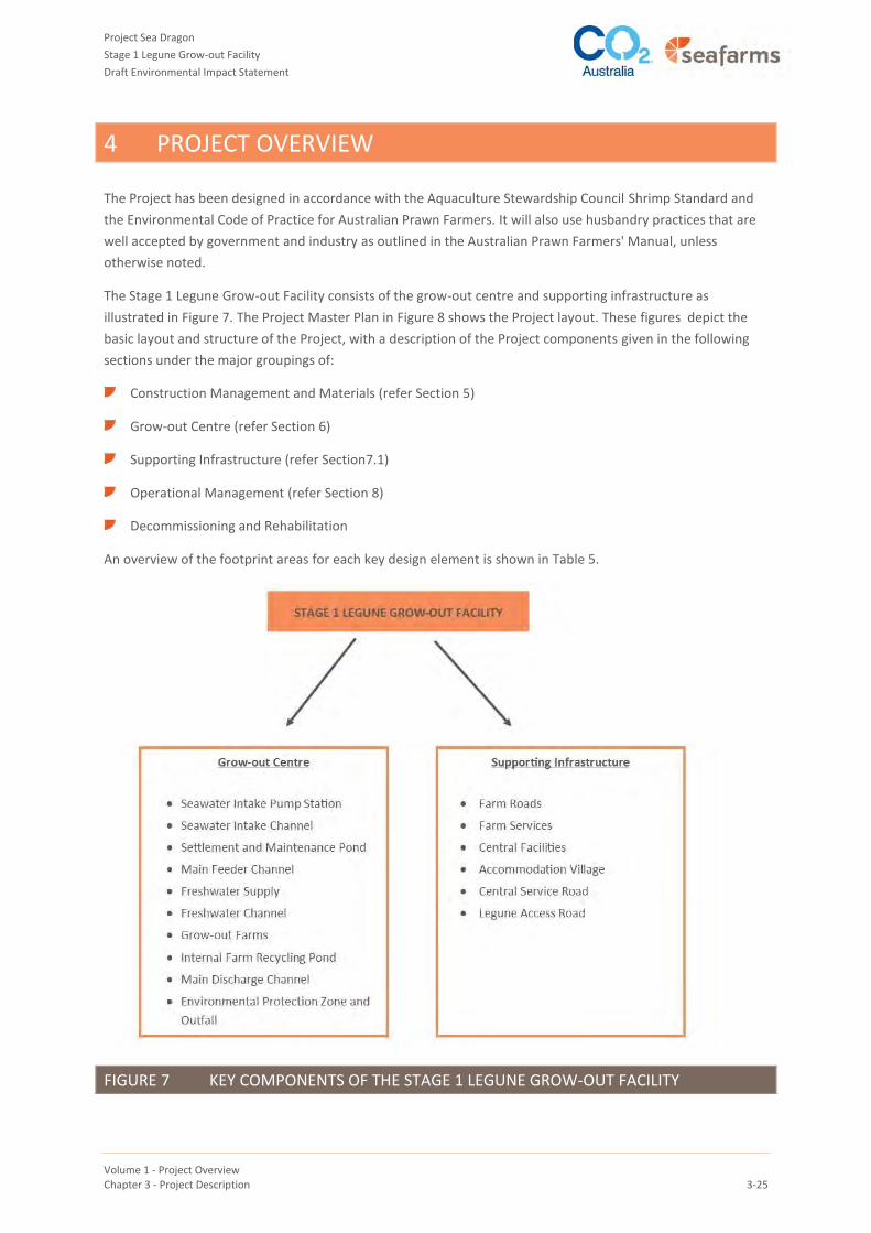
The Stage 1 Legune Grow-out Facility consists of the grow-out centre and supporting infrastructure as
illustrated in Figure 7. The Project Master Plan in Figure 8 shows the Project layout. These figures depict the
basic layout and structure of the Project, with a description of the Project components given in the following
sections under the major groupings of:
Construction Management and Materials (refer Section 5)
Grow-out Centre (refer Section 6)
Supporting Infrastructure (refer Section7.1)
Operational Management (refer Section 8)
Decommissioning and Rehabilitation
An overview of the footprint areas for each key design element is shown in Table 5.
FIGURE 7 KEY COMPONENTS OF THE STAGE 1 LEGUNE GROW-OUT FACILITY

Project Sea Dragon
Stage 1 Legune Grow-out Facility
Draft Environmental Impact Statement
Volume 1 - Project Overview Chapter 3 - Project Description 3-26
FIGURE 8 PROJECT MASTER PLAN
Project Sea Dragon
Stage 1 Legune Grow-out Facility
Draft Environmental Impact Statement
Volume 1 - Project Overview Chapter 3 - Project Description 3 -27
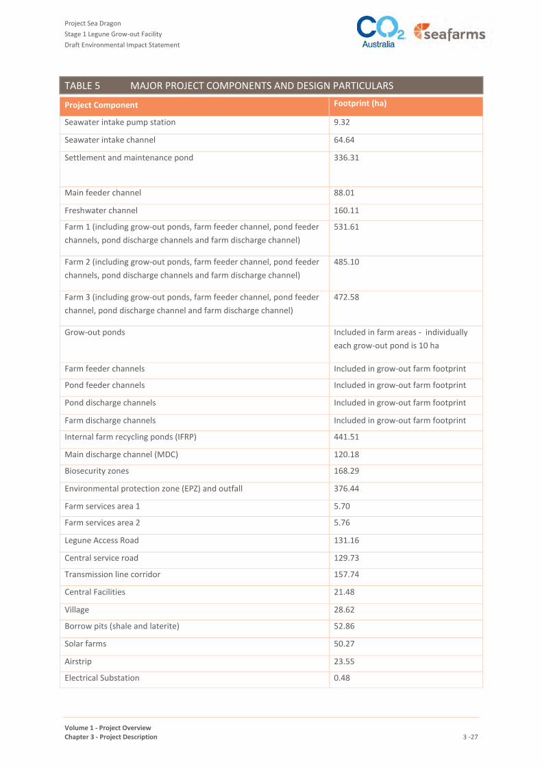
TABLE 5 MAJOR PROJECT COMPONENTS AND DESIGN PARTICULARS
Project Component Footprint (ha)
Seawater intake pump station 9.32
Seawater intake channel 64.64
Settlement and maintenance pond 336.31
Main feeder channel 88.01
Freshwater channel 160.11
Farm 1 (including grow-out ponds, farm feeder channel, pond feeder
channels, pond discharge channels and farm discharge channel)
531.61
Farm 2 (including grow-out ponds, farm feeder channel, pond feeder
channels, pond discharge channels and farm discharge channel)
485.10
Farm 3 (including grow-out ponds, farm feeder channel, pond feeder
channel, pond discharge channel and farm discharge channel)
472.58
Grow-out ponds Included in farm areas - individually
each grow-out pond is 10 ha
Farm feeder channels Included in grow-out farm footprint
Pond feeder channels Included in grow-out farm footprint
Pond discharge channels Included in grow-out farm footprint
Farm discharge channels Included in grow-out farm footprint
Internal farm recycling ponds (IFRP) 441.51
Main discharge channel (MDC) 120.18
Biosecurity zones 168.29
Environmental protection zone (EPZ) and outfall 376.44
Farm services area 1 5.70
Farm services area 2 5.76
Legune Access Road 131.16
Central service road 129.73
Transmission line corridor 157.74
Central Facilities 21.48
Village 28.62
Borrow pits (shale and laterite) 52.86
Solar farms 50.27
Airstrip 23.55
Electrical Substation 0.48

Project Sea Dragon
Stage 1 Legune Grow-out Facility
Draft Environmental Impact Statement
Volume 1 - Project Overview Chapter 3 - Project Description 3 -28
5 CONSTRUCTION MANAGEMENT AND MATERIALS
5.1 SITE ESTABLISHMENT
The following areas will be developed at the start of the construction phase for Stage 1.
Central Facilities: a general construction laydown area will be established to include contractor
administration buildings, temporary services, oil spill management, temporary power generation,
temporary fuel tanks (internally bunded), temporary ablutions and daytime messing facilities, temporary
construction water for soil conditioning if necessary and dust control, warehousing, equipment
maintenance, etc. A concrete batching plant will also be established in this location
Inlet settlement pond area: A construction laydown area will also be established on the floodplain close to
the settlement pond, away from the coastal erosion zone. This will include oil spill management,
temporary power generation, temporary fuel tanks (internally bunded), temporary ablutions and daytime
messing facilities, temporary construction water for soil conditioning if necessary and dust control. This
area will be used for the seawater intake construction, farm earthworks, settlement ponds and channels.
Construction of linear or distributed infrastructure (service corridor, roads, etc.) will be developed using
the appropriate laydown and service areas above, with minor storage of raw materials along the route as
required. Ablutions will be provided from the above areas, or mobile and temporary chemical toilet
facilities.
The lay down areas will be established and basic amenities, waste storage, spill management, fuel storage,
chemical/oil and supply/equipment storage areas developed. Some other specific elements of the Central
Facilities will be constructed at this early phase, to a level suited to construction, with completion to
operational standards when required. This will include:
Wash bay for vehicle washing (aimed at minimising movement of sediment and weeds)
Wastewater treatment system
Potable water treatment plant
Diesel power station (will comprise sufficient temporary and distributed diesel generators until the main
power station is operational).
Storage and management of waste, wastewater, and fuel and other chemicals will be as described in Sections
8.4, 8.4.3 and 8.5.
Unsealed access tracks will be upgraded where required to obtain access to all construction areas.
Site establishment will occur in the earliest part of the dry season possible, with earthworks completed during
the remainder of the dry season, to minimise erosion and sediment loss from the site.
5.2 GENERAL CONSTRUCTION METHODS
Whilst the following sections describe the specific construction method for each Project component, general
methods apply in the construction of a number of components, as described below:
Construction work is expected to take place 6 days per week, for nominally one 10 or 12 hour shift per day.
No nightshifts will be routinely planned, unless scheduled catch-up is required.

Project Sea Dragon
Stage 1 Legune Grow-out Facility
Draft Environmental Impact Statement
Volume 1 - Project Overview Chapter 3 - Project Description 3 -29
Construction includes the testing and commissioning of all mechanical and electrical equipment, and
controls and instrumentation.
All structures, plant, equipment and electrical installations will be required to comply with the relevant
Australian Standards, or where none, Deutsche Industrie Norm (DIN) or American Society for Testing and
Materials (ASTM) standards.
A construction laydown area will be established on the site of the Central Facilities (Section 7.4). It will
include oil spill management, temporary power generation, temporary fuel tanks (internally bunded),
temporary ablutions and daytime messing facilities, temporary construction water for soil conditioning if
necessary and dust control. This laydown area will also include contractor administration buildings,
warehousing and equipment maintenance services. This laydown area will be used for roads and
freshwater channel construction, as well as serving as a construction logistics centre.
The farms services areas (Section 7.3) will be constructed away from the coastal erosion zone, and within
the proposed area of disturbance in the biosecurity zones between the farms and the MFC. These areas
will be used temporarily as construction laydown areas and will be used for the seawater intake
construction, farm earthworks, settlement ponds and channels. A temporary construction village is also
planned for this area, separated from the construction areas and in an area of future biosecurity buffer on
the east side of the MFC. The temporary laydown areas will also include oil spill management, temporary
power generation, temporary fuel tanks (internally bunded), temporary ablutions and daytime messing
facilities, temporary construction water supply, contractor administration buildings, warehousing and
equipment maintenance services.
All earthmoving equipment will be cleaned and inspected for weeds, seeds and other contaminants prior
to mobilising to Legune, and demobilising the site.
Wherever possible, pre-cast concrete will be used in lieu of in-situ concrete. Any in-situ concrete will be
batched at the Central Facilities and trucked to the site.
The farm areas will be control burned of pasture prior to commencement of earthworks, and trees
removed and mulched. No pre-stripping of topsoil is proposed, as all the surface clay soils will be
consumed in the bulk earthworks.
Ponds, channels and berms will be constructed as outlined in Section 5.3
The pond pumping configuration and the channel designs (widths, velocities) have been made to keep the
channel excavations as shallow as possible. This is to keep all elements of the farm constructed in the
shallow, stiffer clay and silty clay soils, and thereby avoid completely the deeper PASS materials.
Whilst PASS materials are not expected in the bulk of excavations, a procedure will be implemented for
any such eventuality. If any PASS material cannot be avoided, the procedures will provide for covering to
eliminate oxidation, containment, and if necessary neutralisation. Procedures will be in accordance with
Queensland Acid Sulfate Soil Technical Manual: Soil Management Guidelines (Dear et al 2014).
The naturally occurring clay soils in the farms are such that large heavy earthmoving equipment, as seen in
mining operations, will be unsuitable. Particularly when the soils are moist, mainly light earthmoving
equipment will be employed, such as Cat 623 and Cat 633 scrapers, and laser buckets drawn by farm
tractors such as Case 550. This methodology was proven by a recent bulk earthworks trial undertaken by
the company between Farms 1 and 2. Another nearby example is the work being carried out by Kimberley
Agriculture Investments Pty Ltd (KAI) on Ord Stage 2, also in black soil plains.

Project Sea Dragon
Stage 1 Legune Grow-out Facility
Draft Environmental Impact Statement
Volume 1 - Project Overview Chapter 3 - Project Description 3 -30
Any references to soil types and characteristics have been made in conjunction with the Douglas Partners
Report on Geotechnical Investigation, 2016, Project Sea Dragon (Douglas Partners 2016).
5.3 POND, CHANNEL WALLS AND BERM CONSTRUCTION
All Ponds, channels, embankments and berms will generally be constructed in the same manner. As for the
general farms area, site clearing will be undertaken via a controlled burn of pasture prior to commencement of
earthworks, and trees removed and mulched. No pre-stripping of topsoil is proposed, as all the surface clay
soils will be consumed in the bulk earthworks.
Construction of ponds and channels will typically be via a cut-to-fill operation to the designed levels. Ponds will
involve the excavation of around 300 mm of the surface clay material to form embankments walls for the
ponds and channels. Excavations for the channels will be deeper than ~300 mm, but are unlikely to be more
than ~1.5m depth. Where poor subsoils exist, the embankment wall base will be placed on geotextiles and/or
geogrids, to ensure wall stability.
The embankment walls for the ponds and the channels will be above-ground earthen structures. Farm walls
will be ~2.0m above the natural ground level. Embankment walls for channels will be ~1.0- 5.0m above natural
ground level.
Any short-fall in quantities will be made up of excess cut from the farm ponds and channels, to achieve an
earthworks balance. Little or no surplus material is expected to be stockpiled for any future use.
Ponds and channels will not be lined with any other materials, as the surface soils (the black clay soils on the
estuarine-deltaic plain) provide the impermeability needed to retain the water for operations, as shown by
both the geotechnical investigations (Douglas Partners 2016) and the on-site trial investigations. Pond and
channel berms will be built to specified design compaction levels to ensure stability, established by the Legune
bulk earthworks trial in June 2016. During construction, compaction of berms will be measured to Australian
Standards for in-situ density and moisture content, for acceptance or rejection.
Batter slopes will be designed to be suitable to obtain the required stability, as generally outlined in
Table 5. Re-vegetation of the batters will be encouraged by seeding with grasses to assist in scour control,
aiming to achieve stability and cover prior to the first rains. The tops of most berms will be sheeted with
roadbase material and compacted for maintenance access, or where relevant will be incorporated into the site
access roads (such as the central service road).
As noted in Section 5.2, procedures will be followed to provide for appropriate management of PASS material
that may be encountered, to avoid oxidation and acid production.
Once the earthworks have been completed, construction of the associated infrastructure will commence.
The major equipment utilised during the construction of these elements includes:
Earthmoving equipment (Laser buckets, tractors, scrapers, trucks, excavators, compactor, graders, dozers,
water carts).
Cranes
Trucks (delivery of materials, bitumen top-coat).

Project Sea Dragon
Stage 1 Legune Grow-out Facility
Draft Environmental Impact Statement
Volume 1 - Project Overview Chapter 3 - Project Description 3 -31
5.4 CONSTRUCTION MATERIALS
5.4.1 Locally Sourced Earth Building Materials
These are primarily the clay soils and materials from designated borrow pits. The black soil clays will be
sourced from the immediate areas of construction. These are suitable, when compacted, to form the
embankments for ponds and channels. These bulk materials will be required in the construction of the
following:
Intake Channel (~370,000 m3)
Settlement Pond (~800,000 m3)
Main Feeder Channel (~2,400,000 m3)
Farms 1, 2 and 3: (~5,700,000 m3)
Main Discharge Channel (~1,000,000 m3)
Legune Access Road) (~170,000 m3)
Central Services Road) (~400,000 m3)
The designated borrow pit at the western abutment of Forsyth Creek Dam is proposed as the shaley material
for general roadbase and sub-base use. In some circumstances this material will be crushed and screened to
produce the material grading required. This material will be used to top the farm ponds for unsealed roads.
Existing lateritic gravel pits will also be utilised to extract and stockpile laterites for road base and topping for
trafficable berms.
Several options for borrow pits as sources of sand for general construction use have been identified - these will
be checked by anthropologists and a suitable one will be selected. Apart from concrete making, this material
will be used for concrete blinding layers and bedding for cables and buried pipes.
5.4.2 Ground Stabilising Materials
Ground stabilizing materials include geotextile (Bidim A44 or equivalent) and geogrid (Tensar SS 30 or
equivalent). The quantities of these are unknown at this stage and will become known as the detailed design is
finalised. In some circumstances it is expected that soils will be conditioned with cement stabilisation,
particularly where water penetration may break down trafficable pavements. Other stabilising materials such
as Neoweb™ may be used by contractors to minimise the quantities of earthworks.
5.4.3 Construction Water
Temporary turkey nest dams will be developed for construction water close to the bulk earthworks sites, for
soil conditioning if necessary, and for dust control. Their specific location will be determined by the contractors
on-site at the time of construction, and may change as construction proceeds.
5.4.4 Precast Concrete
Precast concrete in the form of deck panels, box and pipe culverts and concrete walls will be used extensively
throughout the project to reduce onsite man hours to speed up construction. These structures will be used
primarily around the farms in the inlet and outlet structures, access roads and intake structure. The majority of
these structures are expected to be precast off-site (Kununurra, Perth or Darwin) and transported to site for
installation. Some may be cast on-site and/or tilt-up construction.

Project Sea Dragon
Stage 1 Legune Grow-out Facility
Draft Environmental Impact Statement
Volume 1 - Project Overview Chapter 3 - Project Description 3 -32
5.4.5 Concrete
It is proposed that a small concrete batch plant be established at the Central Facilities on site to provide
concrete for use in building and equipment foundations (at the Central Facilities, Village, HV transmission line
and Farm Services), slabs on grade, bases for inlet / outlet structures, pathways between dongas at the Village
and concrete for miscellaneous works. Aggregate for concrete batching may be trucked in from Kununurra.
Similarly, sand may be trucked in from Kununurra, if the local sand source on Legune proves to be unsuitable.
5.4.6 Fencing Materials
Extensive use of fencing materials will be required throughout the project. This will be mainly in the form of
security fencing and stock fencing. Security fencing will be utilised to divide biosecurity zones, and around
highly dangerous areas (switchyards, kiosks, photovoltaic arrays etc.). Stock fencing will be installed in many
areas to control the movement of cattle into areas of the project where they may cause traffic hazards or
biosecurity risk.
5.4.7 Structural Steel
Structural steel, cladding and miscellaneous steel (handrails, grid mesh, stairs etc.) will primarily be associated
with buildings at the Central Facilities, Village and the Farm Services areas. The Intake pump station and jetty
will contain structural steel as well as miscellaneous steel. Similarly the settlement pond inlet and outlet
structures will contain miscellaneous steelwork. Steel tanks for fuel storage (diesel, potable water) will be
installed during construction, compliant with AS 1692 - Steel tanks for flammable and combustible liquids.
These tanks will be fabricated off-site and transported to site for installation on prepared foundations. The HV
transmission line towers will be fabricated from galvanised steel and will be ~15- 20m high.
5.4.8 Piling
Steel tubular piling (800mm dia. x 20mm) at varying lengths between 25m – 36m will be driven at the Seawater
Intake structure. Sheet piling will be utilised at the Seawater Intake Structure as well as within the IFRPs. Screw
Piling will be utilised for tie-down of most of the prefabricated buildings within the village, Central Facilities and
farm service areas.
5.4.9 Piping Materials
Large bore pipe will be utilised between the Seawater pumps and the Inlet Channel (DN2100 MSCL pipes in
approximately 12m lengths). High density polyethylene (HDPE) pipes will be used for Pond inlets (DN1200 – 2
per pond), each incorporating ~15m of pipe. Sewerage lines within the Village, Central Facilities and the Farm
Services areas will be polyvinyl chloride (PVC) pipe of various diameters. Fuel transfer lines around the storage
facilities within the power plant are yet to be sized. Small bore piping will be used within the Central Facilities,
Village and Farm Services areas for building services (potable water, air etc.).
5.4.10 Mechanical Equipment
Various items of mechanical equipment will be incorporated into the project. These include:
pumps
aerators
control valves
gate valves
sluice gates
screens

Project Sea Dragon
Stage 1 Legune Grow-out Facility
Draft Environmental Impact Statement
Volume 1 - Project Overview Chapter 3 - Project Description 3 -33
drum filters and presses
harvesting equipment (monk screens, dewatering towers, fish pumps, tubs, lighting towers)
workshop equipment
ice making equipment
diesel and dual-fuelled engines and generators
fuel dispensing equipment
laboratory equipment
light vehicles, harvest trucks, feed distribution trucks, general transport vehicles, mini-buses, ambulance
and a fire truck
fixed lifting equipment, hoists and mobile cranes
wastewater treatment packaged plants.
5.4.11 Electrical & Instrumentation Equipment
The majority of the major electrical equipment is associated with power generation and distribution. This
includes:
switchrooms
transformers
switch yard equipment
relays, contactors and de-contactors
Photo Voltaic Systems
Ring Main Units, motor control panels
High Voltage overhead transmission lines
Closed Circuit Television Systems
Transmitters (salinity, flow, depth etc)
5.4.12 Electrical & Instrumentation Bulks
Electrical power and instrumentation and bulks will consist of cable (High Voltage (132kV), Medium Voltage
(22kV) and Low Voltage(415V) – for power, lighting and instrumentation), conduit, cable ladder, termination
boxes, distribution boards, light poles and fixtures.
5.4.13 Mulch
Vegetation cleared in the course of construction will be mulched and stockpiled, for use in landscaping, soil
stabilisation and erosion control.
5.4.14 Other
Wherever feasible, second-hand dongas and pre-fabricated building modules will be purchased for use in
Stage 1.

Project Sea Dragon
Stage 1 Legune Grow-out Facility
Draft Environmental Impact Statement
Volume 1 - Project Overview Chapter 3 - Project Description 3 -34
6 GROW-OUT CENTRE
6.1 OVERVIEW
The Stage 1 Legune Grow-out Facility consists of the grow-out centre and supporting infrastructure. The
processes and infrastructure within the grow-out centre are the key components of the Project. This section
describes all the components of the grow-out centre - from the supply of water through the intake channels to
the growing and harvesting of prawns in the grow-out ponds, and the subsequent discharge of water at the
outfall. This is illustrated in Figure 9.
FIGURE 9 GROW-OUT CENTRE WATER FLOW DIAGRAM
6.2 SEAWATER INTAKE PUMP STATION
6.2.1 Description
As illustrated in Plate 1, a seawater intake pump station will be constructed at Forsyth Creek. The seawater
intake pump structure will comprise:
An open, steel piled jetty structure projecting out into Forsyth Creek, carrying the four intake pumps and
delivery pipes; a davit for installing and removing the pumps for maintenance; and a trolley for
transporting personnel and equipment between the head of the jetty and the roadway at the tail of the
jetty.
The intake bell-mouth at the inlet to the pump will be fitted with a 100 mm aperture mesh grille, to
exclude larger material. The grille will be regularly cleaned of marine fouling by raising the pump assembly

Project Sea Dragon
Stage 1 Legune Grow-out Facility
Draft Environmental Impact Statement
Volume 1 - Project Overview Chapter 3 - Project Description 3 -35
up and onto the jetty platform, so that personnel access can be afforded safely and the fouling wastes
collected without any need for floating plant. Plate 1 shows a typical bell-mouth intake pipe with the
immersed section raised for maintenance.
PLATE 1 TYPICAL BELL-MOUTH INTAKE PIPE
Electrical power distributed to the pump station via an overhead line and a localised electrical sub-station.
Pipelines delivering seawater into the intake channel. The pipes will be either mild steel, cement-lined, or
fibreglass, each of approximately 2.1 m outside diameter.
An outline of the pump station is shown in Figure 10.
The area of the intake comprises marine sediments. The length of the jetty structure has been designed to
place the pumps in the naturally occurring deeper water in Forsyth Creek, and an allowance has been made for
the forecast bank erosion for the life of the structures. The pump station has been designed to be constructed
and maintained from the land, without requiring marine craft or dredging, owing to the high tides and high
tidal currents.
6.2.2 Construction
The intake structure will be constructed via the installation of an earthen access ramp from the estuarine-
deltaic plain out onto the coastal plain to Forsyth Creek to provide access for the piling rig. This ramp will be
reclaimed after use and the earth material used elsewhere on the site, such as the intake channel berm
earthworks. The jetty will then be constructed using tubular steel piles, spaced approximately 6 m apart. Pile
diameters will be approximately 750 mm diameter. Piles will be driven to refusal, and designed with the
strength to withstand the horizontal and vertical loads without needing bracing or other structure in contact
with the ground. This will allow water to flow through the structure with little impedance. The piles will be
driven by a construction method called ' launch beam method' starting from the hard ground 70 m back from
the shoreline. This is an elevated beam that is supported by the first few driven piles. The beam will be
cantilevered forward to each new pile position, carrying the crane and piling hammer, tools and workers. This
means that cranes and equipment do not have to be supported by the soft marine muds. It is a proven method,
frequently used in over-water construction.

Project Sea Dragon
Stage 1 Legune Grow-out Facility
Draft Environmental Impact Statement
Volume 1 - Project Overview Chapter 3 - Project Description 3 -36
FIGURE 10 SEAWATER INTAKE STRUCTURES CONCEPT ELEVATIONS
Project Sea Dragon
Stage 1 Legune Grow-out Facility
Draft Environmental Impact Statement
Volume 1 - Project Overview Chapter 3 - Project Description 3 -37
Upon completion of the piling the structural supporting steel will be installed, comprising headstocks, girders
and bracing, followed by the placement of the precast concrete deck panels. The installation of the pumps,
piping and electrical will follow.
The major equipment utilised during the construction of this element includes:
earthmoving equipment (trucks, excavator, compactor, grader)
pile driving rig (likely to be a diesel hammer)
cranes
trucks (delivery of materials)
welding machines (steel and pipe)
equipment refuelling and lubes.
Approximately one third of the piling and structural/mechanical erection work will be over water, necessitating
special hazard controls and emergency response training and capability.
6.2.3 Operation
The seawater pumps are designed to operate generally from mid-tide to high tide daily, to bring in the cleanest
available seawater from Forsyth Creek, thus minimising the volume of suspended solids imported to the farms,
and to minimise pumping costs. The projected peak extraction rate is 12.5 m3/s for 12 hours per day for
18 days to enable the filling of the farm ponds after a harvest. Pipes from the pump station will gravity feed
seawater into the seawater intake channel.
6.3 SEAWATER INTAKE CHANNEL
The seawater intake channel will commence at a point close to Forsyth Creek, but set back sufficiently to avoid
the predicted future extent of the naturally occurring river scour. The location of the channel adjacent to the
pump station is shown on Figure 8.
The top level of the embankment has been designed to allow for high intensity rainfall events (freeboard), to
prevent over-topping. The width of the intake channel has been sized to handle the anticipated volume of
seawater delivery for the potential full-scale project, and at the same time ensuring sufficient velocity to
minimise settlement of suspended sediments. Figure 11 shows the typical cross-section of the channel.
Construction of the Seawater Intake Channel will be as described in Section 5.3, with the addition that
embankment walls will be armoured for any storm surge and future sea level rise. Batter slopes shown in
Table 5 have been specifically chosen to ensure no collapse, or slip-circle failure of the underlying marine clays.
The Seawater Intake Channel will feed the settlement pond by gravity via a concrete weir.
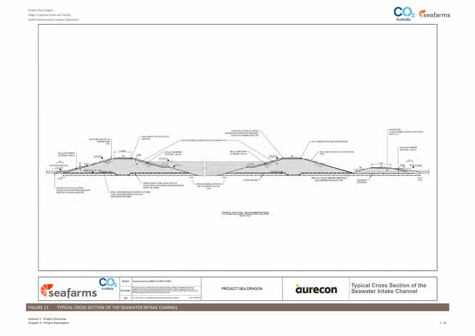
Project Sea Dragon
Stage 1 Legune Grow-out Facility
Draft Environmental Impact Statement
Volume 1 - Project Overview Chapter 3 - Project Description 3 -38
FIGURE 11 TYPICAL CROSS SECTION OF THE SEAWATER INTAKE CHANNEL

Project Sea Dragon
Stage 1 Legune Grow-out Facility
Draft Environmental Impact Statement
Volume 1 - Project Overview Chapter 3 - Project Description 3 -39
6.4 SETTLEMENT AND MAINTENANCE POND
6.4.1 Description
A single settlement pond will be located at the end of the Seawater Intake Channel (refer to Figure 8). The
settlement pond has been designed to settle and store sediments, with periodic removal of sediments to the
maintenance pond. It will be gravity fed by the intake channel via a pre-cast concrete weir structure, and will
discharge via gravity to the Main Feeder Channel, also via a pre-cast concrete weir structure.
The settlement pond has been sized to maximise the efficiency of settling out suspended sediments in the
incoming seawater, and minimise suspended sediments entering the downstream channels and farms.
A number of methods have been considered for the periodic removal of sediment from the settlement pond,
along with the timing options. A two-pond sedimentation system, allowing one pond to be emptied and dried
out whilst the other continues to operate, was ruled out on the basis of unnecessary cost, and larger than
necessary footprint at the scale of Stage 1 operations. An alternative system was adopted, utilising one
settlement pond, and a smaller maintenance pond to store the sediments to be removed periodically from the
settlement pond. The maintenance pond will be situated in an area to be previously used as a source of clay
material for building the intake channel and settlement pond (i.e. a borrow pit), as illustrated in Figure 8. The
purpose of the maintenance pond (as further described in Section 6.4.3) is to store and solar dry sediments
accumulated in the settlement pond for subsequent removal to landfill or for use in building future berms and
channels.
6.4.2 Construction
The ponds will be constructed as described in Section 5.3, on the Legune estuarine-deltaic plain at or above
RL 4.5 m AHD, being higher ground than the intake channel, and thus with minimised exposure to storm surge
and future sea level rise impacts. A typical cross-section of the settlement pond wall is shown Figure 12.
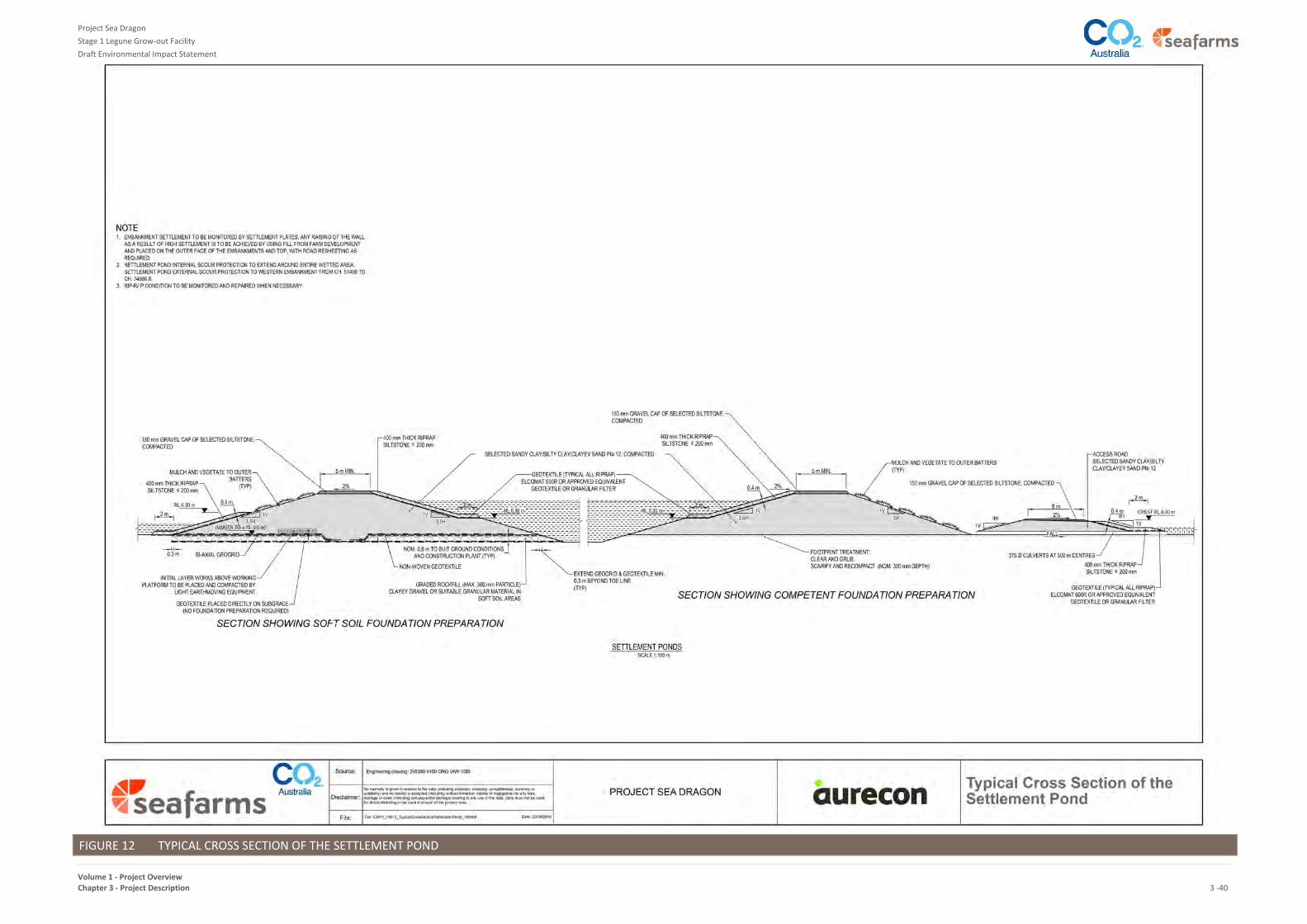
Project Sea Dragon
Stage 1 Legune Grow-out Facility
Draft Environmental Impact Statement
Volume 1 - Project Overview Chapter 3 - Project Description 3 -40
FIGURE 12 TYPICAL CROSS SECTION OF THE SETTLEMENT POND
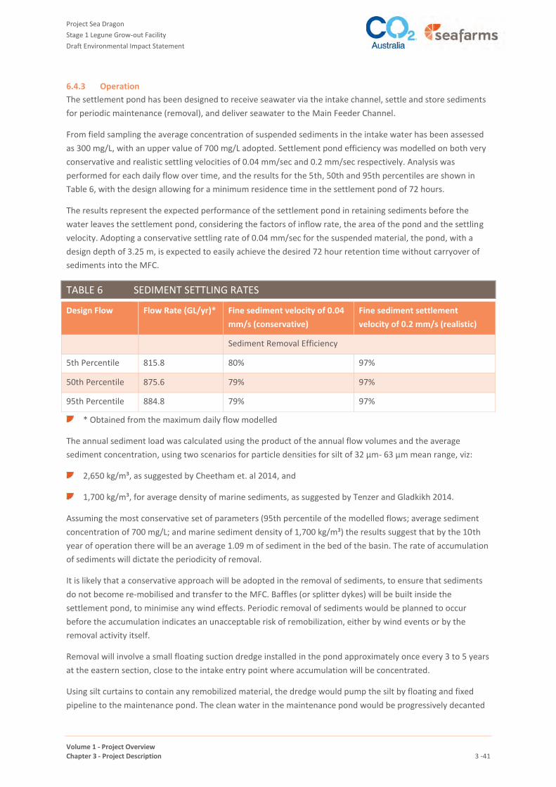
Project Sea Dragon
Stage 1 Legune Grow-out Facility
Draft Environmental Impact Statement
Volume 1 - Project Overview Chapter 3 - Project Description 3 -41
6.4.3 Operation
The settlement pond has been designed to receive seawater via the intake channel, settle and store sediments
for periodic maintenance (removal), and deliver seawater to the Main Feeder Channel.
From field sampling the average concentration of suspended sediments in the intake water has been assessed
as 300 mg/L, with an upper value of 700 mg/L adopted. Settlement pond efficiency was modelled on both very
conservative and realistic settling velocities of 0.04 mm/sec and 0.2 mm/sec respectively. Analysis was
performed for each daily flow over time, and the results for the 5th, 50th and 95th percentiles are shown in
Table 6, with the design allowing for a minimum residence time in the settlement pond of 72 hours.
The results represent the expected performance of the settlement pond in retaining sediments before the
water leaves the settlement pond, considering the factors of inflow rate, the area of the pond and the settling
velocity. Adopting a conservative settling rate of 0.04 mm/sec for the suspended material, the pond, with a
design depth of 3.25 m, is expected to easily achieve the desired 72 hour retention time without carryover of
sediments into the MFC.
TABLE 6 SEDIMENT SETTLING RATES
Design Flow Flow Rate (GL/yr)* Fine sediment velocity of 0.04
mm/s (conservative)
Fine sediment settlement
velocity of 0.2 mm/s (realistic)
Sediment Removal Efficiency
5th Percentile 815.8 80% 97%
50th Percentile 875.6 79% 97%
95th Percentile 884.8 79% 97%
* Obtained from the maximum daily flow modelled
The annual sediment load was calculated using the product of the annual flow volumes and the average
sediment concentration, using two scenarios for particle densities for silt of 32 µm- 63 µm mean range, viz:
2,650 kg/m³, as suggested by Cheetham et. al 2014, and
1,700 kg/m³, for average density of marine sediments, as suggested by Tenzer and Gladkikh 2014.
Assuming the most conservative set of parameters (95th percentile of the modelled flows; average sediment
concentration of 700 mg/L; and marine sediment density of 1,700 kg/m³) the results suggest that by the 10th
year of operation there will be an average 1.09 m of sediment in the bed of the basin. The rate of accumulation
of sediments will dictate the periodicity of removal.
It is likely that a conservative approach will be adopted in the removal of sediments, to ensure that sediments
do not become re-mobilised and transfer to the MFC. Baffles (or splitter dykes) will be built inside the
settlement pond, to minimise any wind effects. Periodic removal of sediments would be planned to occur
before the accumulation indicates an unacceptable risk of remobilization, either by wind events or by the
removal activity itself.
Removal will involve a small floating suction dredge installed in the pond approximately once every 3 to 5 years
at the eastern section, close to the intake entry point where accumulation will be concentrated.
Using silt curtains to contain any remobilized material, the dredge would pump the silt by floating and fixed
pipeline to the maintenance pond. The clean water in the maintenance pond would be progressively decanted

Project Sea Dragon
Stage 1 Legune Grow-out Facility
Draft Environmental Impact Statement
Volume 1 - Project Overview Chapter 3 - Project Description 3 -42
back to the settlement pond until the suspended sediment load in this return water is too high. The remaining
pond residue would be solar dried until stiff enough to be picked up by mechanical means (truck and
excavator; or dragline) and carted to the landfill areas between farms, or stockpiled for use in building future
berms and channels (refer to Section 8.1.11 for more information on this material).
The frequency of pond maintenance would be established after a period of operations and data collection on
the rate of accumulation. The suggestion of 3 to 5 years above is a reflection that high frequency would result
in thin layers of material in the maintenance pond, and thereby least difficulty in solar drying and re-handling
within a dry season.
6.5 MAIN FEEDER CHANNEL (MFC)
The MFC (refer to Figure 8) will be constructed on the floodplain to receive seawater from the settlement
pond, and deliver it to farms by gravity. The rate of delivery will be dictated by the salinity measured in the
farms, for the daily variations, and by the farm filling rate when the farm is being re-filled. The outflow from the
MFC to farms will be controlled by the farm inlet control gates. Water level in the MFC is not expected to vary
significantly, because as the farms take water from the MFC it is regularly replenished from the seawater intake
system, via the settlement pond. It is not expected to accumulate sediments to the extent that maintenance
and removal is warranted.
Figure 13 shows a typical cross-section of the MFC alongside the Freshwater Channel (FWC). The MFC has been
designed to deliver seawater by gravity to each farm without the need for further pumping.
Construction of the channel will be as described in Section 5.3.
6.6 FRESHWATER SUPPLY
6.6.1 Description
Freshwater is required for the grow-out farms, to balance and maintain the required salinity range in the
periods of high evaporation. Freshwater supply for Stage 1 aquaculture operations will be drawn from the
existing Forsyth Creek Dam (see Figure 2). The dam has a capacity of 35 GL, and is currently used to extend the
carrying capacity of cattle in selected paddocks over the drier months of August to October each year.
6.6.2 Construction
The outlet to the existing dam will be modified to provide the seasonal control of outflows, by an additional
valve and modified weir box on the downstream face of the wall. This will also allow periodic maintenance of
the outlet without reverting to the current practice of emptying the dam fully to gain access to the outlet valve.
The outlet will discharge to a new channel, designed to handle the flows more efficiently than the current
release practice.
6.6.3 Operation
Stage 1 operations are expected to draw nominally 7 to 10 GL per annum from the dam (the actual amount
required will depend upon climatic variability in particular evaporation and precipitation). It is this freshwater
addition which will ensure a high level of farm water recycling, thereby minimising the intake and outfall
quantities.
The current cattle operations' practice of flood release nominally each August will not be continued once the
aquaculture activities commence. Whilst it is planned that the cattle numbers will be reduced to a small degree
in the Stage 1 operations, it is also proposed that more efficient use of the freshwater from the dam may be
implemented by pumped and piped irrigation from the new FWC to selected paddocks, to extend the pasture.

Project Sea Dragon
Stage 1 Legune Grow-out Facility
Draft Environmental Impact Statement
Volume 1 - Project Overview Chapter 3 - Project Description 3 -43
FIGURE 13 TYPICAL CROSS SECTION OF THE MAIN FEEDER CHANNEL
Project Sea Dragon
Stage 1 Legune Grow-out Facility
Draft Environmental Impact Statement
Volume 1 - Project Overview Chapter 3 - Project Description 3 -44
6.7 FRESHWATER CHANNEL (FWC)
6.7.1 Description
As illustrated in Figure 8, freshwater will be delivered from the existing Forsyth Creek Dam to the grow-out
farms by an open channel referred to as the FWC. The route of this channel was chosen as the high ground
between the Forsyth Creek and Alligator Creek systems, thus avoiding altering any of the natural overland
flows, as shown in Figure 14.
The FWC will vary in width according to the channel hydraulic profile, and has been designed to avoid scour
and siltation. A typical cross-section is presented in Figure 15.
The FWC follows the terrain to avoid interruption of any existing overland flows in the wet season, i.e., the
catchment boundary between the Alligator Creek and the Forsyth Creek catchment. At the 10.5km mark,
measured along its length from the dam, the profile from there to the farms is a flat water level, with a
constant crest height for the remainder of its length, allowing for a freeboard allowance of 0.5m. Water is
gravity fed from the dam outlet, for the full length of the FWC.
Construction of the channel will be as described in Section 5.3.
Freshwater will be released from Forsyth Creek Dam to the FWC via the dam outlet. Freshwater will then be
lifted from the FWC by a pump adjacent to each farm, and piped into the farm for delivery into the Farm
Feeder Channel, for mixing and salinity control.
6.8 FARMS
6.8.1 Description
As depicted in Figure 8 and Figure 16 to Figure 18, the Stage 1 Legune Grow-out Facility includes three grow-
out farms (Farm 1, Farm 2 and Farm 3). Typically each farm consists of the following elements, also shown in
Figure 9:
a Farm Feeder Channel (FFC) and Pond Feeder Channels (PFC) (see Section 6.9)
between 36 (Farms 2 and 3) and 40 ponds (Farm 1) (see Section 6.10)
Pond Discharge Channels (PDC) (see Section 6.11)
a Farm Discharge Channel (FDC) (see Section 6.11)
an Internal Farm Recycling Pond (IFRP) (see Section 6.12).
The farms also comprise farm roads (see Section 6.13) and shared farm services (see Section 7.3). Figure 16 to
Figure 18 illustrate the layout of each farm.
Farms will be separated to minimise the potential transfer of disease. Between farms, and between main
distribution channels and farms, will be nominal biosecurity areas generally comprising a separation distance of
not less than 250 m (refer to Section 8.2). The purpose of these buffers is also to satisfy the following criteria:
no seepage between farms
no movement of animals (crabs) between farms
no movement of parts of prawns (by birds) between farms

Project Sea Dragon
Stage 1 Legune Grow-out Facility
Draft Environmental Impact Statement
Volume 1 - Project Overview Chapter 3 - Project Description 3 -45
provide wildlife corridors for movement of terrestrial fauna
allow access by people.
These areas will be fenced and used for farm support services, storage for pond sludge, and temporary
construction facilities. To avoid ponding of water in these areas spoon drains will be installed where required,
and drained to natural run-off, including release drains under the Main Discharge Channel where necessary.
6.8.2 Construction
Specific construction methodologies for each farm component (FFC, PFC, ponds, PDC, FDC, IFRP, farm roads
and farm services) are described in Sections 6.9 to 7.3.
6.8.3 Operation
Farms will operate independently of each other, but coordinate in respect of water balance. The
interconnection of farms and channels (FWC, MFC and MDC) is shown on Figure 19. The total farm system has
been designed as an “all-in; all-out” water management model for termination harvests, i.e. all ponds will be
successively harvested, drained, and left fallow for a period. When the fallow period coincides with the dry
season these fallow periods will be used to completely dry out ponds and channels for maintenance and
disease control.
6.8.3.1 Seawater
Each farm will have a gravity fed inlet channel controlling seawater distribution from the Main Feeder Channel.
At this point the seawater will be filtered to 100 microns by large rotating drum filters. Each filter will have a
capacity of 1.0 m³/sec, and the number of filters installed will depend on the particular operational flow.
During farm filling (from empty, such as after a farm fallow period) a total of 12 filters will be installed. Two of
these will be permanently fixed at this location, to handle the average daily intake. The remaining 10 filters
may be mobile, shared with the other filter station at the IFRP, and only used temporarily at this inlet location
during farm filling.
Seawater is required to fill the ponds, and provide continuous make-up during the course of the crop until
harvest. The seawater will be utilised to maintain the pond water demand, in conjunction with the separately
distributed fresh water. The seawater intake volume will be minimised by continual recycling of the farm water
through the IFRP, via the Pond Discharge and Farm Discharge Channels, and filtered again prior to returning to
the Farm Feeder Channel for re-use in the farm ponds. The seawater demand may be further minimised from
time to time where the water in the outgoing MDC is of suitable quality for recovery back into the IFRP.
The filtrate will be separated by a continuous filter back-wash function. The filtrate will be pumped and piped
in a 100mm PVC pipe to the MDC for retention and mixing with the farm discharge during the high flows
associated with harvest pumping).
6.9 FARM FEEDER CHANNEL (FFC) AND POND FEEDER CHANNEL (PFC)
Each farm will include an FFC and three or four PFC, depending on the individual farm layout. The FFC will
distribute the filtered seawater and filtered water from the IFRP to the ponds via the PFC by gravity. Each FFC
and PFC has been designed to deliver sufficient water to allow 6 ponds to be filled concurrently in a 3 day
period, and thus, the total farm to be filled in 18 days. Water movement will be controlled by the inlet gate to
the FFC and the inlet gate on each pond. Initially these gates may be manually controlled, but ultimately they
may be automated and computer controlled. Ponds cannot be over-filled by this operation, as the pond outlet
has a weir to prevent this.
The FFC and PFC will be constructed as outlined in Section 5.3.

Project Sea Dragon
Stage 1 Legune Grow-out Facility
Draft Environmental Impact Statement
Volume 1 - Project Overview Chapter 3 - Project Description 3 -46
FIGURE 14 FRESHWATER CHANNEL

Project Sea Dragon
Stage 1 Legune Grow-out Facility
Draft Environmental Impact Statement
Volume 1 - Project Overview Chapter 3 - Project Description 3 -47
FIGURE 15 TYPICAL CROSS SECTION OF THE FRESH WATER CHANNEL

Project Sea Dragon
Stage 1 Legune Grow-out Facility
Draft Environmental Impact Statement
Volume 1 - Project Overview Chapter 3 - Project Description 3 -48
FIGURE 16 FARM 1 LAYOUT
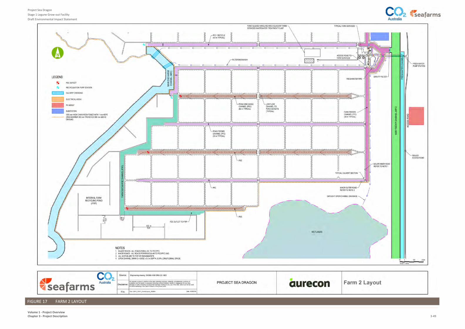
Project Sea Dragon
Stage 1 Legune Grow-out Facility
Draft Environmental Impact Statement
Volume 1 - Project Overview Chapter 3 - Project Description 3-49
FIGURE 17 FARM 2 LAYOUT

Project Sea Dragon
Stage 1 Legune Grow-out Facility
Draft Environmental Impact Statement
Volume 1 - Project Overview Chapter 3 - Project Description 3 -50
FIGURE 18 FARM 3 LAYOUT

Project Sea Dragon
Stage 1 Legune Grow-out Facility
Draft Environmental Impact Statement
Volume 1 - Project Overview Chapter 3 - Project Description 3 -51
FIGURE 19 INTERCONNECTION OF FARMS AND CHANNELS

Project Sea Dragon
Stage 1 Legune Grow-out Facility
Draft Environmental Impact Statement
Volume 1 - Project Overview Chapter 3 - Project Description 3 -52
6.10 PONDS
6.10.1 Description
Prawns will be grown in large grow-out ponds, which are sized and configured to optimise human capital. Each
farm will consist of up to 40 ponds, with each being 10 hectares in size. Each pond will have one inlet structure
to control the movement of water into the pond, and one outlet structure. These structures will be fitted with
penstock gates with the outlet structure comprising:
a stop-log to control water retention and release5
a fixed screen to prevent escape of the prawns
an upstream compartment (monk), to permit a harvesting cage and fish pump to be inserted during times
of harvest
a downstream compartment for a mobile pump to draw down the water levels before and during the
harvest (harvest pump) and discharge into the PDC.
The stop-log will be designed to allow automatic overflow to the PDC in high intensity storm events, so that the
ponds are not overtopped in the minor design level storm event. For events greater than the minor design
event up to the major design event level, the stormwater will be managed by controlled release gravity
drainage through the downstream weir structures from Pond and Farm Discharge Channels and the IFRP and
then to the MDC (refer to Table 5 for design events). For greater than the major design event, a lined swale will
be provided in the berm of the outermost channel (Pond Feeder Channel or Pond Discharge Channel) facing
the biosecure zone, for planned release to the environment. In such events the salinity of the water being
released is expected to be very diluted by the rainfall event.
Figure 20 shows a typical cross-section of the pond outlet structure, with concurrent harvesting and pumping
activities in action.
The pond floor will have a contoured base with slopes and shapes designed to efficiently drain the pond during
harvest, and dry it out for the fallow period. Each pond will be designed to drain freely during harvest with
minimum 0.3 m water differential between pond invert and the mobile harvest pump inlet structure. Figure 21
shows the pond floor design.
The Pond Discharge Channel water surface level will be 0.5 m below that of the ponds, to allow a gravity purge
from the pond and the PDC to the IFRP at times when the water recycling requires acceleration. The system will
be designed for partial harvests, in addition to the full termination harvests, as a means of management of the
pond biomass.
5 stop logs consist of horizontal timbers or flashboards spanning between vertically slotted piers in a weir
structure, which may be inserted into, or removed, from the vertical slots by hand or with a hoist, controlling
the weir crest height
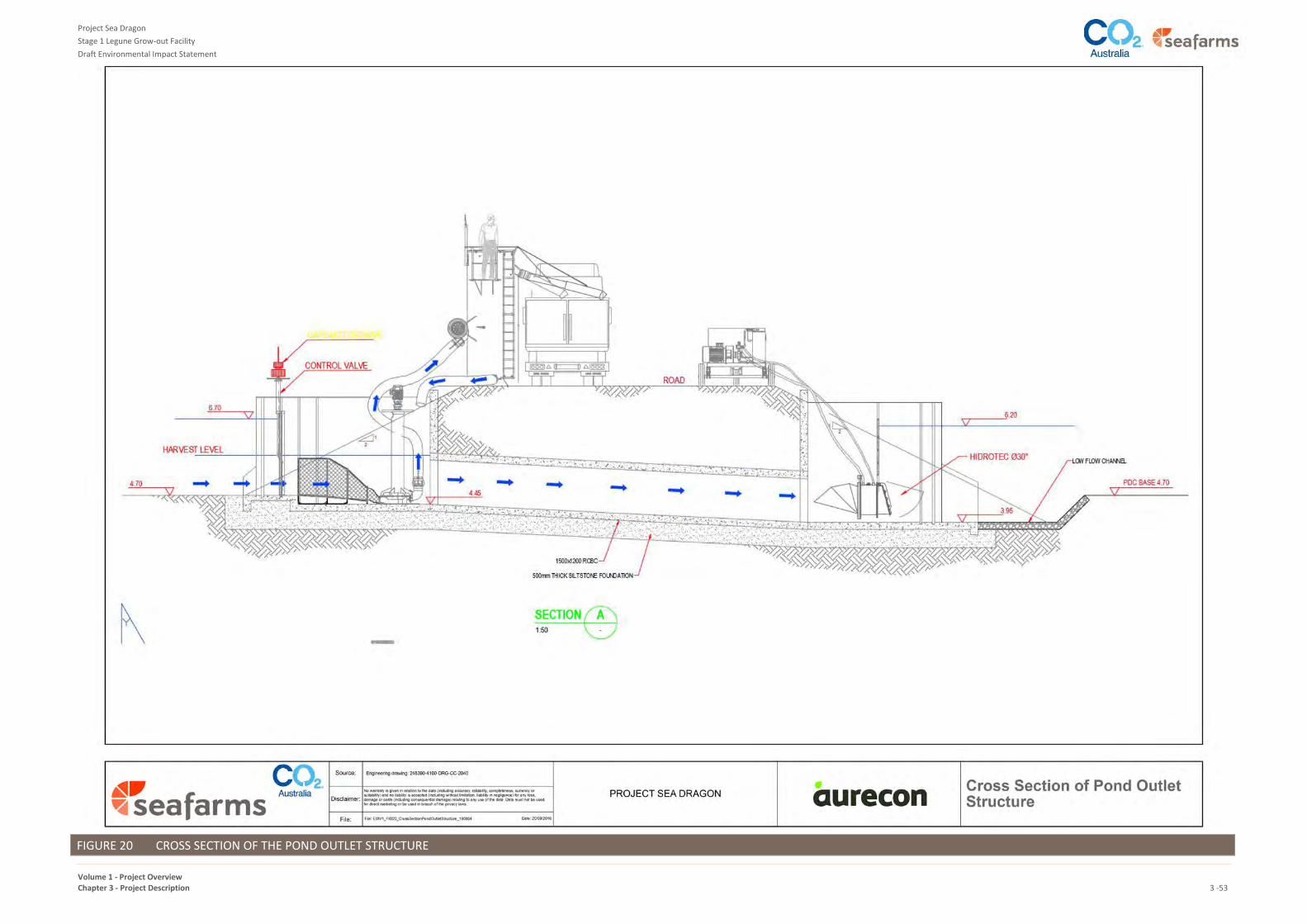
Project Sea Dragon
Stage 1 Legune Grow-out Facility
Draft Environmental Impact Statement
Volume 1 - Project Overview Chapter 3 - Project Description 3 -53
FIGURE 20 CROSS SECTION OF THE POND OUTLET STRUCTURE

Project Sea Dragon
Stage 1 Legune Grow-out Facility
Draft Environmental Impact Statement
Volume 1 - Project Overview Chapter 3 - Project Description 3 -54
FIGURE 21 TYPICAL POND PLAN

Project Sea Dragon
Stage 1 Legune Grow-out Facility
Draft Environmental Impact Statement
Volume 1 - Project Overview Chapter 3 - Project Description 3 -55
6.10.2 Construction
Ponds will formed by excavating a thin layer (nominally 300 mm) of the locally occurring surface clay soil on the
base of the pond, to form bund walls as outlined in Section 5.3, designed to retain a nominal water depth of 1.5
m for prawn grow-out.
Batter details are shown in Table 5, and it is expected that batter slopes may require some annual re-profiling.
This will be done during farm fallow and refurbishment before re-stocking. Vegetation of the batters will be
encouraged by seeding with grasses to assist in scour control.
Once the earthwork activities for each pond have been completed, the inlet, outlet and other pond structures,
as well as electrical equipment, will be installed. Pond inlet structures will be made in either pre-cast concrete
or High Density Polyethylene (HDPE). Once these structures have been installed the electrical cabling will be
trenched and laid in the berms around the ponds and connected to the equipment.
The major equipment utilised during the construction of the ponds includes:
earthmoving equipment (Laser buckets, scrapers, trucks, excavators, compactor, graders, dozers, water
carts)
cranes
trucks (delivery of materials)
plate compactors and small rollers
ditch diggers
HDPE pipe cutting, welding, equipment
equipment refuelling and lubes.
6.10.3 Operation
Operation of the ponds involves water supply management, water quality management, pond stocking,
aeration, prawn feeding, harvesting and management between crops. These processes are described in more
detail in Section 8.1 which outlines the prawn farming process.
6.11 POND DISCHARGE CHANNELS (PDC) AND FARM DISCHARGE CHANNEL (FDC)
Each farm will include 2 or 3 PDCs, depending on the individual farm layout, and an FDC. Depths vary slightly
from farm to farm according to the base level of the ponds and the length of channels, with falls to ensure that
all water retaining structures can be fully drained for the fallow periods. Mobile pumps may be used in the PDC
to keep it dry during the fallow period, to ensure the ponds in turn are kept dry.
Ponds will discharge to the PDC which outfall to the FDC by gravity. The PDC has been sized for conveyance of
water from six ponds at one time during harvest. Water from the FDC will then flow to the IFRP. The top 0.5m
will flow by gravity over a weir, for the normal day-to-day farm recycling and any intense rain events (greater
than the design event). The remainder of the water depth will be lifted into the IFRP via a pump station, for the
harvesting operations and farm emptying operations.
The PDC and FDC will be constructed as outlined in Section 5.3.

Project Sea Dragon
Stage 1 Legune Grow-out Facility
Draft Environmental Impact Statement
Volume 1 - Project Overview Chapter 3 - Project Description 3 -56
6.12 INTERNAL FARM RECYCLING POND (IFRP)
6.12.1 Description
As shown in Figure 8 each farm includes an IFRP for storage, settlement and return of water to the Farm Feeder
Channel for re-use. The IFRP is sized to be nominally equivalent to a minimum of 30 per cent of the farm pond
volume. The volume contained in the FDC will be considered as part of the 30% IFRP requirement where the
velocity is sufficiently low to promote settlement of particulates. Figure 16 to Figure 18 show the IFRP for each
farm. Each IFRP will be shaped differently, according to the terrain and area available between the farm and
the edge of the floodplain. The nominal water depth in the IFRP will be 1.5 m generally, for biological control,
but varied where necessary to:
minimise construction excavation into the underlying silty clay layer, and completely avoid the deeper
PASS if it occurs, and
contour the pond floor with centre spoon drains, to enable the pond to be emptied and dried at times of
pond maintenance.
6.12.2 Construction
Construction of the pond will be as described in Section 5.3.
6.12.3 Operation
Water from the FDC will be fed into the IFRP as described in Section 6.11. Water from the IFRP will be:
filtered and pumped into the Farm Feeder Channel via an adjacent Pond Feeder Channel for re-use in the
farm, or
released to the MDC in times of:
harvesting or
high water levels, due to intense rainfall events or
high salinity release.
Water being re-used in the farm will be put through 100 micron drum filters. A bank of up to 12 filters will be
required for this function, sized for the peak daily recirculation volume. As for the farm inlet filters, as
described in Section 6.8.3, the filtrate will be separated by a continuous filter back-wash function and pumped
to the MDC for retention and mixing with the farm discharge during the high flows associated with harvest
pumping.
Maintenance of the IFRP is expected each 6 to 7 years of operation. After that nominal period of operation a
volume of accumulated silt and organic matter at the base of the recycling pond will likely detract from the
performance of the settlement and treatment function. Maintenance will comprise:
Emptying the IFRP at the same time as the farm is dewatered for maintenance. Water that cannot be
pumped to the Main Discharge Channel by the fixed recycle pumps will be removed by temporary sump
pumps, also to the Main Discharge Channel.
Drying the pond base for an extended period of weeks in the dry season, during the farm fallow period.
Removal of the layer of sediments by earthmoving equipment (front end loader and truck).

Project Sea Dragon
Stage 1 Legune Grow-out Facility
Draft Environmental Impact Statement
Volume 1 - Project Overview Chapter 3 - Project Description 3 -57
The material removed will be placed in the designated area in the separation zone between farms, as for the
farm pond waste. As the floodplain currently experiences high erosion naturally in the wet season, this
material, high in organics, is likely to provide a beneficial use close to the grow-out farms.
6.13 MAIN DISCHARGE CHANNEL (MDC)
6.13.1 Description
As illustrated in Figure 8 the MDC will be located on the floodplain to receive water released from the IFRP, and
deliver it to the Environmental Protection Zone. The width and height of the MDC will vary according to the
terrain, and will be sized to handle the peak harvest discharge volumes from the farms. A weir will be
constructed at the interface of the MDC and the EPZ, to control water levels and flows.
Figure 22 shows typical cross-sections of the MDC, one where the underlying soils may be too weak to carry
the bund wall, requiring reinforcement, and one where the soils are sufficiently strong without the need for
geogrid reinforcement.
6.13.2 Construction
Construction of the channel will be as described in Section 5.3.
6.13.3 Operation
During operation the MDC will receive water from the IFRP and deliver it to the EPZ.
Peak discharge to the MDC will occur when a terminal harvest and a partial harvest occur concurrently (see
Section 8.1.8 for an explanation of the different types of harvest). Harvest pumps will discharge at 4 m3/s on
the basis of only one pond being harvested per day in a terminal harvest, and one partial harvest concurrently.
When all production ponds on a farm are emptied, the PDC may also be drained, using harvest pumps. This
water may be discharged to the MDC, or held in the IFRP.
Ability to pump water from the MDC back to each farm will be provided, so that recycling can be maximised
when the MDC water is within the requisite salinity levels at certain times of the year. This is designed to
conserve the freshwater supplies from the Forsyth Creek Dam and reduce the volume of seawater intake. An
allowance for mobile pumps has been made for this function.
Storms up to the design event will be handled within the capacity of the bund walls of the MDC and EPZ. For
events greater than the design event, the stormwater will be released to the environment, through controlled
release lined swales (or low points in the bund wall).

Project Sea Dragon
Stage 1 Legune Grow-out Facility
Draft Environmental Impact Statement
Volume 1 - Project Overview Chapter 3 - Project Description 3 -58
FIGURE 22 TYPICAL CROSS SECTION OF THE MAIN DISCHARGE CHANNEL

Project Sea Dragon
Stage 1 Legune Grow-out Facility
Draft Environmental Impact Statement
Volume 1 - Project Overview Chapter 3 - Project Description 3 -59
6.14 ENVIRONMENTAL PROTECTION ZONE (EPZ) AND OUTFALL
6.14.1 Description
The primary function of the EPZ is to regulate the flow of the discharge water by reducing the velocity and
holding the water so that discharge can be timed to the ebb tides and can be discharged at a constant level of
410 ML/day during those ebb tide releases. The majority of the discharge will flow through a 100 m wide
channel in the centre of the EPZ, but the EPZ is sized for 'overflow' of this channel, to enable it to hold the peak
discharge and water from storm events, up to the 50 year ARI event, and it is expected that this 'overflow' and
the margins of the channel itself will be colonised by local samphire and/or mangrove species, which will assist
in nutrient uptake. The initial concept for the EPZ was to plant this area with suitable species in order to
construct the wetland, however, it was subsequently decided, upon review of the relevant literature and
consultation with prawn farm operators, to let the EPZ colonise naturally. In other words, the preference, is to
construct the biological components of the wetland through colonisation. This colonisation will be monitored
throughout the Stage 1 operations and will be used to inform decision making and design for subsequent
stages. It remains open to implement an establishment program utilising direct seeding or planting should
colonisation processes be inadequate.
Given the above, the project is designed to achieve the required water quality objectives without relying upon
the nutrient uptake benefits conferred by an EPZ. However, it is expected that the EPZ will provide for some
decay of nutrients prior to discharge. The level expected of decay is likely to increase over time commensurate
with the vegetation colonisation and monitoring will be undertaken during Stage 1 to understand the levels of
nutrient uptake. However, as the expected level cannot be precisely quantified with a high level of confidence,
there has, conservatively, been no decay rate factored into any of the discharge modelling undertaken for the
project (see Volume 2, Chapter 2, Marine and Estuarine Water for further details).
The EPZ will be constructed primarily on the estuarine-deltaic plain. It will receive water from the MDC and
deliver it to Alligator Creek outfall (see Figure 8). Figure 23 shows the layout and detail of the construction of
the EPZ. For Stage 1 with just three farms, the area and therefore the width will be limited to 100 m wide, as
described above. This is to ensure both that standing water is minimised to avoid stagnation, and to maintain
the required retention time. Weirs will be placed at the interface of the MDC branches and the EPZ, to regulate
the flows accordingly.
A weir will be constructed at the outfall to Alligator Creek to guide the flow from the EPZ. The weir has been
sited taking into consideration the natural high scour regime of Alligator Creek and seasonal movements of the
creek sedimentation (Figure 24). Justification for the siting of the outfall in this location is provided in Volume
5, Appendix 10 Forsyth and Alligator Creek Bank Erosion Assessment. Avoidance of mangroves and
construction activities in the intertidal zone were also considerations in the selection of the outfall location.
The weir will provide the control of outflows between the EPZ and the daily tidal fluctuations in Alligator Creek.
The timing and volume of ebb tide releases will be automated through adjustable gates (penstocks) in the
sheetpiled weir structure. Electronic commands for the gate operation will be via the Central control function
(room), where operations planning inputs will be integrated with tidal data, farm harvest and daily discharge
data, rainfall forecasts, and data from the field monitoring devices.
In the unlikely event of loss of telemetry signals or other malfunction, the gates will be capable of manual local
operation. Road access will be provided along the top of the MDC and EPZ berms for this purpose.
The gates in the weir will be proprietary supplied equipment, such as that provided by Rubicon Pty Ltd,
pictured in Plate 2 below.

Project Sea Dragon
Stage 1 Legune Grow-out Facility
Draft Environmental Impact Statement
Volume 1 - Project Overview Chapter 3 - Project Description 3 -60
FIGURE 23 ENVIRONMENTAL PROTECTION ZONE LAYOUT
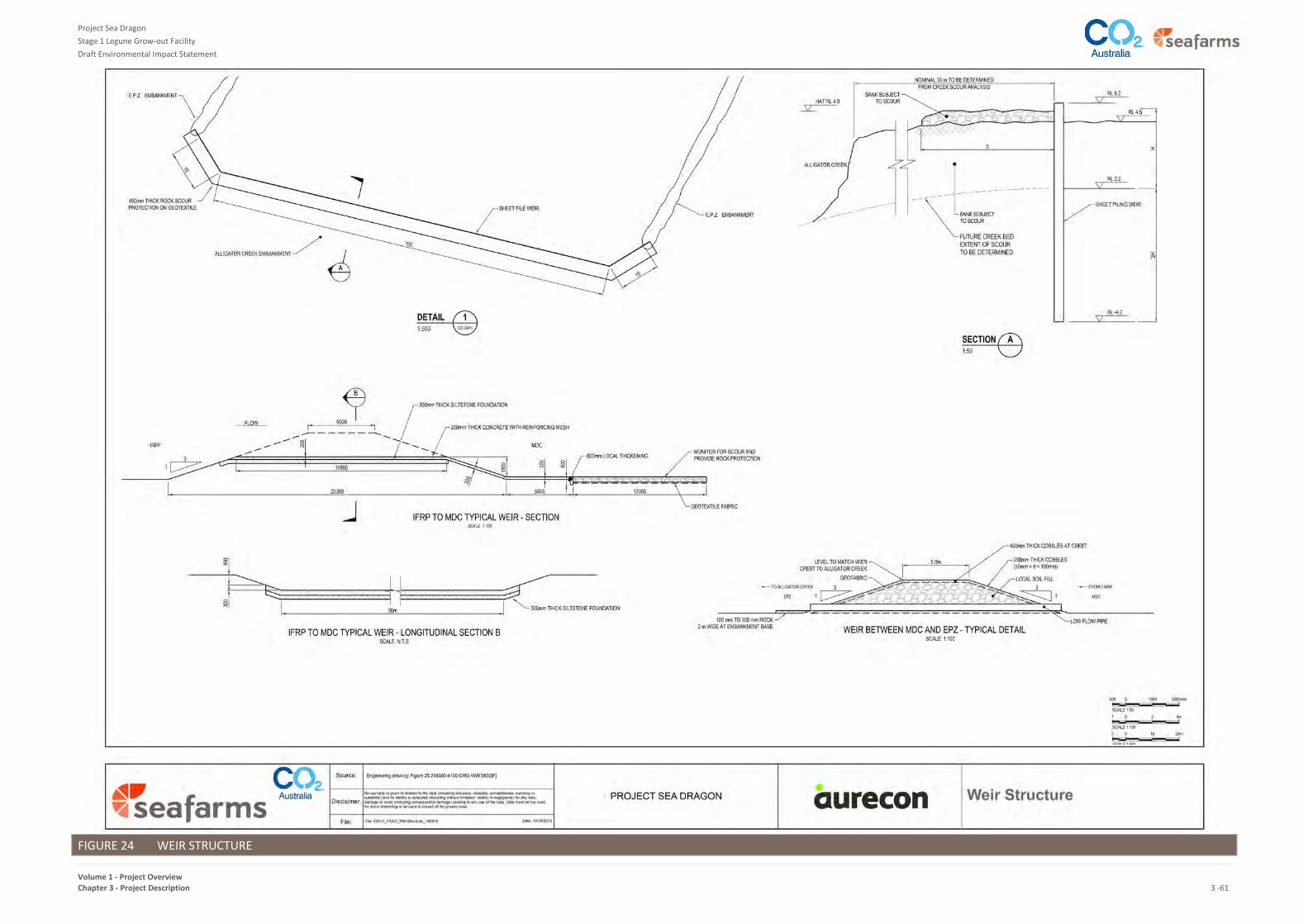
Project Sea Dragon
Stage 1 Legune Grow-out Facility
Draft Environmental Impact Statement
Volume 1 - Project Overview Chapter 3 - Project Description 3 -61
FIGURE 24 WEIR STRUCTURE

Project Sea Dragon
Stage 1 Legune Grow-out Facility
Draft Environmental Impact Statement
Volume 1 - Project Overview Chapter 3 - Project Description 3 -62
The gates will be supplied with integral controls. Power will be supplied by solar PV, with diesel emergency
supply back-up. The gates will control flow through automatic programmed settings or alternatively manual or
semi-automatic operation, for gates 'shut', 'open' or 'partially open', according to the desired discharge
volumes and timing. Instrumentation will transmit CCTV signals and water levels. The weir will have a walkway
for personnel access.
PLATE 2 EXAMPLE WEIR GATES
6.14.2 Construction
The EPZ walls will be constructed as described for berms and channel walls in Section 5.3. The weir will be
constructed in steel sheet piling, for part of its length (the wing walls). At the overflow point the weir will be a
concrete gate structure mounted on the sheet piling under, to support the proprietary gates. Gates may be
flume gates or vertical knife gates. Final selection will be made in the detailed design phase. Sheet piling will
be driven by a land based piling rig (truck mounted), owing to the wall being set back from the creek
embankment a nominal 30m. The earth will be graded and levelled to enable the truck mounted rig to traverse
to and from the area.
Whilst the sheet piling will penetrate through any PASS material, no such material will be otherwise disturbed,
brought to the surface or exposed to the atmosphere. The sheet piling will be selected with adequate thickness
for long-term corrosion allowance. A walkway will be added to the top of the piling to permit personnel access,
for monitoring and maintenance of instruments.
The concrete gate structure over the sheet piling sub-structure will be pre-cast concrete, manufactured off site.
6.14.3 Operation
As described above, during operation the EPZ will provide a buffer between the daily discharges from the farms
and the tidal fluctuations in Alligator Creek. The area has been designed to handle low flow periods (daily
turnover) and peak discharge periods (farm harvesting). It has been sized hydraulically to convey the
concurrent farm discharges plus stormwater events up to 50 year ARI events. The retention time of farm
releases are calculated combining the capacities of the MDC and EPZ.

Project Sea Dragon
Stage 1 Legune Grow-out Facility
Draft Environmental Impact Statement
Volume 1 - Project Overview Chapter 3 - Project Description 3 -63
7 SUPPORTING INFRASTRUCTURE
7.1 OVERVIEW
The Stage 1 Legune Grow-out Facility consists of the grow-out centre and supporting infrastructure. This
section describes the supporting infrastructure and services for the grow-out facility, including:
Farm Roads
Farm Services
Central Facilities
Accommodation Village
Central Service and Legune Access Roads.
7.2 FARM ROADS
In-farm access roads to and from the ponds will be all weather, unsealed gravel-sheeted construction to allow
for year round harvesting, stocking, feed delivery and general access by farm equipment.
In-farm roads will be constructed on the trafficable bunds forming the ponds, channels and IFRP, designed for a
maximum 10 t medium rigid truck, with a design speed of 30 km/hour.
Farm bridges may be formed with precast concrete culverts, polyethylene (HDPE) pipes or similar durable cost-
effective structures. Gravel sheeting for roads will be from the designated approved borrow pits on Legune
Station.
7.3 FARM SERVICES
As depicted in Figure 8, two Farm Services areas will be constructed to service Farms 1, 2, and 3. Each farm
services area includes:
administration, accommodation and laboratory buildings (manager’s house, short-term accommodation
units, common mess and living areas for day and night shift staff, administration office and laboratory)
a wash bay for vehicle washing between biosecurity zones
workshops for light farm vehicles and aerators
fuel, chemical, molasses and other material and waste stores
transport of post larvae tub storage
a wastewater treatment facility and spray field for discharge of treated water
potable water treatment and storage, for human consumption
electrical substations.
The two shared farm service areas are identical and are shown in Figure 25.

Project Sea Dragon
Stage 1 Legune Grow-out Facility
Draft Environmental Impact Statement
Volume 1 - Project Overview Chapter 3 - Project Description 3 -64
FIGURE 25 FARM SERVICES LAYOUT

Project Sea Dragon
Stage 1 Legune Grow-out Facility
Draft Environmental Impact Statement
Volume 1 - Project Overview Chapter 3 - Project Description 3 -65
Construction of the farm services will comprise:
Earthworks and drainage, using small earthworks plant (grader, excavator, truck, trenching plant). The
earthworks platform for the area will have been completed prior to the construction of the farm services,
during the bulk earthworks activities for the ponds and channel. The bulk earthworks will raise the area
1.0m, for wet season flood immunity.
In-ground plumbing, for water supply and sewerage.
Concrete footings and ground slabs, for buildings, tanks, sumps, substations, etc. Use of pre-cast concrete
fabricated offsite will be maximised wherever possible.
Prefabricated building units will be trucked to the site and lifted into place by crane.
Installation of the prefabricated packaged wastewater treatment, by crane.
Electrical and instrumentation cabling and connections
Commissioning and testing of all equipment.
First fills and stocking of consumables.
The different aspects of the farms services listed above is described in the following subsections.
7.3.1 Administration, Accommodation and Laboratory Buildings
All buildings will comply with the Building Code of Australia, including cyclone rating requirements for Region C,
and relevant Australian Standards, and will generally comprise of steel framed, fully insulated wall, roof and
floor framing lined externally in prefinished steel and internally with decorative finished plywood walls and
ceilings and vinyl finished CFC (compressed fibre cement) floors. The ceiling height will be a minimum of
2400mm (2700mm for the administration and laboratory buildings), with powder coated doorframes and metal
clad doors.
The farm manager will live on site, and be responsible for all farm operations. The manager's house will be a
modular transportable house, possibly second hand.
The farm manager will be supported by shift personnel, some of whom will be required to stay overnight to be
readily on hand at all times. These staff will be supported by the Central Village, as required, for victualling,
laundry, transport to/from farms, etc. This will also comprise of second hand prefabricated units.
The administration and laboratory functions carried out on farm will be those that cannot be done at the
Central Facilities, generally for reasons of immediacy or biosecurity control.
7.3.2 Wash Bay for Vehicle Washing Between Biosecurity Zones
Entry and exit to farms will be strictly controlled for biosecurity reasons, and a vehicle wash bay comprised of a
drive-through bay will be utilised for all vehicle traffic. Generally, farm vehicles will stay on-farm, and only leave
for major maintenance or replacement.
Wash bays will be automatic drive-through facilities, using benzalkonium chloride (BKC) as a disinfectant in the
spray, fully concreted, with containment pit, automated sprays, and a sump and pump to manage wash wastes
(further described in Section 8.4.3).

Project Sea Dragon
Stage 1 Legune Grow-out Facility
Draft Environmental Impact Statement
Volume 1 - Project Overview Chapter 3 - Project Description 3 -66
7.3.3 Workshops for Light Farm Vehicles and Aerators
Workshops comprising prefabricated metal clad sheds on concrete floors will be provided for the activities of
aerator maintenance, light vehicle servicing, and storage of mechanical and electrical spares. Secondhand
Seatainers may be used initially, as shown in Plate 3.
PLATE 3 TEMPORARY SEATAINER WORKSHOP SETUP
Farm vehicles will comprise 4x4 utes (Hilux or equivalent), tractors, dinghies, light trucks and quad bikes. These
will essentially remain within the farm Zone 4 biosecurity zone, except when taken offsite to Kununurra for
replacement, or overhauls and other maintenance that cannot be carried out on-farm.
Aerator maintenance consists of cleaning the aerators of marine fouling, repairs, general servicing and testing.
Wash pads and laydown areas will be provided for these activities. Any solid wastes from the marine fouling
will be collected to be combined with the pond waste.
At any one time there will be between 860 and 960 aerators operating in each farm, with additional numbers
at the store or in the workshop for maintenance. Alternatively, a contract arrangement may be developed to
truck these units off site to a commercial Kununurra maintenance shop.
7.3.4 Fuel, Chemical, Molasses and Other Material and Waste Stores
Fuels will be used on farm for farm vehicles and temporary generators, which will be equipped with double-
lined day tanks. Day tanks will be replenished by a mobile diesel tanker according to demand.
Waste, fuel, molasses and chemical storage will be as described in Section 8.5.
Other storage requirements include a storage area for tubs transporting post larvae, which will comprise a flat
concrete slab on ground.
7.3.5 Transporting Post-Larvae Prawns
Post-larvae prawns (PL’s) will be trucked to the farms from the Hatchery near Darwin at approximately 15 days
old. Special purpose built tanks will be manufactured for the trucking operation. The tanks will be designed and
built for temperature control, ammonia scrubbing and alarms, to care for the animals in transport.
The frequency of trucks from the Hatchery is expected to be 1 per day during stocking of farms.
7.3.6 Wastewater Treatment Facility and Spray Field for Discharge of Treated Water
A gravity sewer, on-site wastewater facility and land disposal area will be utilised for the sewerage scheme, as
further described in Section 8.4.3.

Project Sea Dragon
Stage 1 Legune Grow-out Facility
Draft Environmental Impact Statement
Volume 1 - Project Overview Chapter 3 - Project Description 3 -67
7.3.7 Potable Water Treatment and Storage
Potable water use on the farms will be limited to personal use in the accommodation and administration units,
use in testing and washing in the laboratory and washdown in the workshops. Potable water will be obtained
from the freshwater supply to each farm, as further described in Section 8.6.
7.3.8 Electrical Substations
Electricity will be transmitted from the power station at the Central Facilities (refer Section7.4.1.6) by 132 kV by
overhead lines, and stepped down to 22kV at each farm substation. Power will be then distributed around each
farm at 22kV in underground cables to approximately 10-12 transformer kiosks where it will be stepped down
to 415V.
Substations and kiosks will be weather-proofed skid-mounted pre-fabricated units, to house motor control
panels (MCP’s), switch panels, distribution boards, fire protection, instrumentation and controls equipment,
etc. Large transformers will be in blast-resistant blockwork enclosures, with oil collection sumps.
Power to all field equipment area lighting, buildings, aerators and pumps will be 415V. Power to
instrumentation and field devices will be 48V or less.
Packaged standby generators will be distributed to selected kiosk units, to provide emergency power for
aeration to the ponds in the event of power station blackout or lightning strike to the transmission line. These
standby units may be skid-mounted or on trailers.
Electrical sub-stations are static facilities, and are not frequented by farm operations personnel. Only qualified
electricians will have access to these facilities.
7.4 CENTRAL FACILITIES
7.4.1 Description
The Central Facilities are located approximately 15 km to the south-west of the grow-out farms as depicted in
Figure 8, and their layout is shown in Figure 26. These facilities have been centrally located to:
minimise exposure of the facilities to wet season flood, by virtue of the terrain elevation
minimise the daily travel distance for much of the workforce between the facilities and the
Accommodation Village.
achieve manpower efficiency, by sharing services and facilities, and minimising duplication of services
between farms where possible.
The area will be fenced, with gate and security controls according to the biosecurity zoning as set out in the
PSD Biosecurity Manual (refer to Section 8.2).
Trafficable areas of the Central Facilities will be bituminised. Stormwater will be directed to open swale drains
to take the run-off to the floodplain. An area outside the perimeter fencing shown in Figure 26 is the
designated fire break to the Central Facilities. All structures will be designed to handle Category ‘C’ cyclone
wind loading, whether or not the structures are second-hand or new.

Project Sea Dragon
Stage 1 Legune Grow-out Facility
Draft Environmental Impact Statement
Volume 1 - Project Overview Chapter 3 - Project Description 3 -68
FIGURE 26 CENTRAL FACILITIES SITE LAYOUT PLAN

Project Sea Dragon
Stage 1 Legune Grow-out Facility
Draft Environmental Impact Statement
Volume 1 - Project Overview Chapter 3 - Project Description 3 -69
The functions to be carried out at the Central Facilities broadly include:
harvest equipment storage and maintenance
harvest handling area
vehicle washing
slurry ice-making
equipment maintenance and warehousing
power generation and switchyard
energy storage and fuel dispensing
management, administration, fire, security, safety and paramedic
communication and systems controls
security and biosecurity control
laboratory
wastewater treatment
7.4.1.1 Harvest Equipment Storage and Maintenance
Plant and equipment to be used for harvesting prawns will be stored at the harvest handling area in the Central
Facilities when not in use, or alternatively parked at the farms. This includes plastic tubs, 8 t flatbed trucks,
steel cages, mobile dewatering towers, mobile fish pumps and piping.
This equipment will be shared between farms, and will therefore be washed for biosecurity reasons,
maintained and stored in this area (Zone 2 - see Section 8.2).
7.4.1.2 Harvest Handling Area
Harvest trucks passing in and out of the harvest handling area will be washed in the automatic truck washing
bay. The details of this wash bay will be identical to the farm wash bays (refer Section 7.3.2). Figure 26
illustrates the layout of the harvest handling area at the Central Facilities.
There will be a Cross Dock where the 8t trucks bringing the harvest from the farms will transfer the tubs
containing the prawns onto Pantech trucks, for transport to the processing plant north of Kununurra, WA (to
minimise the number and frequency of trucks travelling on the highway to Kununurra). The Cross Dock will be
an air-conditioned insulated steel clad structure, with double doors, loading docks and an elevated platform for
loading and unloading tubs.
The principal purpose of the Cross Dock is to minimise the frequency of trucks travelling on the highway to
Kununurra. This will be achieved by transferring tubs from 8-tub flat-bed harvest trucks to the higher capacity
highway trucks, carrying up to 44 tubs on a Pantech truck. The requirement for air-conditioning is to prevent
deterioration of the ice slurry where the tubs are retained or delayed in the transfer process.
For Stage 1 the typical traffic for the peak sequence of 1x terminal harvest plus 1 x partial harvest on a given
night will likely comprise:
44 flat-bed harvest trucks from farm to the Cross Dock, and
15 Pantech trucks from the Cross Dock to Kununurra, travelling at 80 km/h average speed.

Project Sea Dragon
Stage 1 Legune Grow-out Facility
Draft Environmental Impact Statement
Volume 1 - Project Overview Chapter 3 - Project Description 3 -70
7.4.1.3 Vehicle Washing
The vehicle wash bay at the entry to the harvest transfer area (Zone 2 biosecurity - see Section 8.2) will
comprise a drive-through bay, concrete containment pit, automated sprays, and a sump and pump. Harvest
trucks will wash upon entry and departure of this area (refer to Section 8.4.3 for details on wastewater
management).
The Pantech trucks taking the harvest in tubs do not enter Zone 2. They will remain in Zone 1, and therefore
will not be washed at Legune.
7.4.1.4 Slurry Ice Plant
The slurry ice plant will be built in the harvest handling area in the Central Facilities and will deliver slurry ice, at
a capacity of 50 tubs per hour, to the empty harvest tubs on the 8 t harvest trucks prior to despatch to the farm
for harvesting. 300 kg of ice slurry plus PrawnFresh (a safe and non-residual product that controls the onset of
melanosis in prawns, allowing for a much longer shelf life) will be placed in each tub. Water for the ice making
and slurry will come from the potable water supply (refer to Section 8.6).
7.4.1.5 Equipment Maintenance and Warehouse Facilities
Maintenance facilities for minor equipment maintenance will comprise a general workshop at the Central
Facilities. Any major repairs will be carried out offsite by specialist companies in Kununurra and beyond.
Workshops are likely to comprise a concrete floor and fabric shade structures supported by Seatainers. Hard
standing areas will be bituminised. The area of workshops is expected to be approximately 2,000 m².
Oil/water separation and treatment will be fitted at the washbays and vehicle maintenance areas, as further
described in Section 8.4.3.
Warehousing will comprise a structural steel clad shed, with internal racking and an office, of approximately
1,500 m².
7.4.1.6 Power Generation, Transmission and Distribution
Initially power will be provided by small standalone packaged generating sets of 1MW and 2MW size, located
at each farm substation and at the Forsyth Creek seawater pump sub-station. Ultimately these generating sets
will remain in those locations as back-up power to enhance the system reliability (with diesel storage), with an
integrated power supply and transmission system developed to supply the site.
As the operations gain momentum and positive cash flow develops, a central power station will be developed
with a transmission line connecting all the major loads and back-up units via substations. This power station
and switchyard have been sited integrally with the Central Facilities for flood immunity and workforce
efficiency reasons, as shown in Figure 26. This will be supplemented with a distributed solar photovoltaic (PV)
generation capacity.
Power generation for all the Legune electrical needs will comprise an integrated system including:
A central thermal station, consisting of multiple duel fuelled engines, powered by diesel initially. The
capacity of thermal engines is expected to be 17.5 MW capacity, sized for the night-time load.
Distributed solar PV generation of approximately 17.5 MW capacity for the daytime load.
A control system (Danvest or similar) that will maximise the solar penetration, by allowing some of the
thermal engines to run on no-load, thus providing the spinning reserve necessary to back up the
renewables in the event of sudden cloud events.

Project Sea Dragon
Stage 1 Legune Grow-out Facility
Draft Environmental Impact Statement
Volume 1 - Project Overview Chapter 3 - Project Description 3 -71
A 132 KV transmission overhead line will transmit power to the farms and pump stations. At the seawater
intake pump station and at the Farm Services area a switchyard will be provided with transformers to step
down the power to 22 KV and 415 V according to the distribution design.
As depicted in Figure 8, the solar farms will be developed at five separate locations (outside of the Central
Facilities), to minimise the outages from isolated clouds.
7.4.1.7 Energy Storage and Fuel Dispensing
A fuel storage and transfer station will be sited adjacent to the thermal power station at the Central Facilities.
Diesel and petrol storage will be in double-lined self-bunded steel tanks (suitably protected from corrosion).
Refuelling facilities will be in bunded areas.
It is anticipated that in future Stages liquified natural gas (LNG) supplies may become available for the project,
with LNG being trucked from Darwin or similar in isotankers. Allowance has been made for this in the footprint
of the Central Facilities, but the LNG supply does not form part of this Stage 1 proposal.
Alternatively, in future years it may be possible for a gas pipeline to be developed, bringing gas into the Central
Facilities for the thermal engines from known nearby gas reserves. Such onshore reserves in the Joseph
Bonaparte Gas Basin are under consideration by third parties, including Advent Energy and Beach Energy, but
do not form part of this proposal.
Consideration of LNG supplies or a regional gas pipeline only becomes feasible at a larger scale than Stage 1,
hence will not be investigated until future stages of the project (as described in Section 2.8.6) undergo their
approvals processes.
7.4.1.8 Management, Administration, Fire, Security, Safety and Paramedic
The administration building will be sited close to the Central Facilities gatehouse and comprise a prefabricated
structure on cyclone rated footings. The building will be sized to accommodate the administration workforce
plus training rooms.
Separate prefabricated structures will be provided for security, safety and paramedic functions. An ambulance
and a fire truck will be stationed at this location.
The existing unsealed Legune airstrip will be maintained for emergency purposes and have the capability to
handle the Royal Flying Doctor Service.
7.4.1.9 Airstrip
Allowance has been made to extend the length of the existing unsealed runway to handle larger turbo-prop
aircraft, in the event that flights to and from Kununurra and Darwin are justified.
Currently the airstrip is 1000 m long. To handle aircraft up to Beechcraft 1900D size, the strip will be
lengthened by 600 m, and widened from 23 m, to 30 m. This would be done by adding compacted gravel,
extending the strip westwards further into an open grassed paddock. The area will be fenced, and airport
lighting added, new gable markers, wind sock and instrumentation, to allow commercial operators to service
the project, providing day/night small freight and passenger services.
7.4.1.10 Communication and Systems Controls
All equipment will have manual over-ride local controls as well as remote operation. Critical plant will have
back-up controls and remote CCTV (closed circuit television), with senior staff having the ability to monitor and
control equipment from farms and the 24 hour manned control room at the Central Facilities. Instrumentation
includes:

Project Sea Dragon
Stage 1 Legune Grow-out Facility
Draft Environmental Impact Statement
Volume 1 - Project Overview Chapter 3 - Project Description 3 -72
water level monitoring, for all critical channels
water quality monitoring, for dissolved oxygen (DO), salinity, conductivity, etc
cloud data, for automatic control of the electrical control system switching between solar and thermal
engines
condition monitoring alarms for critical equipment, including over-temperature, start-stop failure, etc
CCTV for visual monitoring of critical gates, control devices and security
GPS (global positioning system) tracking of vehicles.
Pumps, valves and gates to common infrastructure such as the seawater intake, Main Discharge Channel, EPZ
and Freshwater Channel will be connected to controls for remote operations. Field devices will be utilised
throughout the Grow-out area, recording data for water level, water quality, fault alarms, environmental data,
etc. These will be monitored and controlled from the Central Control Room. The control system will be a
distributed control network consisting of I/O (input/output), processors and operator interfaces.
Field devices will be deployed through the farms and common water infrastructure, recording flow, turbidity,
conductivity, temperature, dissolved oxygen and pH.
The processors will be in each of the 22kV kiosks distributed throughout the Grow-out area, and the control
system divided by farms and process areas. Devices within farms will be monitored and managed locally at
each farm services area, with the remainder being controlled form the Central Control Room. Monitoring of all
statuses and alarms will be through desktop supervisory control and data acquisitions (SCADA) screens.
Control room operators will be in contact with each farm manager and field staff via voice modulated radio,
providing instantaneous access to information out in the field. This includes power demand and control of
power generation and distribution. Selected staff will be delegated with control responsibilities according to
the Grow-out area management protocol.
Mobile plant will be installed with human machine interface (HMI) units and touch panels, to be visually
equivalent to the desktop SCADA system, for seamless interoperability.
A mixture of fixed and PTZ (pan-tilt-zoom) IP (internet protocol) cameras will be installed at critical facilities
such as power supply kiosks, pump stations and discharge gates. Visual monitoring of farms will be provided by
IP cameras at strategic locations around the farms.
Communications to Legune will be upgraded by provision of either fibre optic cable from Kununurra, or
microwave. The site will have the capability to run a full coverage mobile phone service, plus high capacity
internet for data transfer for the business. A Telstra or other PoP (point-of-presence: satellite, microwave or
Fibre) will be provided at Legune Station, with a 24 core fibre from the telecommunications hut to the Central
Control Room. A communications backbone will be provided from the Central Control Room to the farms and
Seawater Intake substation via the 132kV transmission line.
Pumps, gates, valves, filters, water and wastewater treatment plant, standby generators and aerators within
each farm will be controlled by the farm manager or on-farm delegate. Each farm control network will be a
redundant ring encompassing the 22kV substation supplying the farm and each kiosk on the 22kV ring main,
utilising 24 core single mode optical fibres in conduit underground.
The farm will use wireless network base stations and subscriber units providing access to the control system via
HMI panel in operator truck and utility vehicles.

Project Sea Dragon
Stage 1 Legune Grow-out Facility
Draft Environmental Impact Statement
Volume 1 - Project Overview Chapter 3 - Project Description 3 -73
A fire network will facilitate all Fire Indication Panel (FIP) communication and other non-process safety
communications. The fire network will be limited to buildings as determined by AS 1670, including substations,
power station, Central Facilities, Accommodation Village and farm dwellings.
7.4.1.11 Security and Biosecurity control
Biosecurity will be managed by zoning, security gates, CCTV and a system of electronic passes (RFID) for
personnel accredited to work in the applicable zones. This is further described in Section 8.2.
All personnel entering the property will be guided by fencing to the Central Facilities main gate and security
entrance, or to the Accommodation Village. This gate control will apply to the cattle station personnel and
operations, as well as the approved Traditional Owners. The approved Traditional Owners will be offered
employment, inter alia, to assist Project Sea Dragon with security, personnel access, any escorting of visitors
and other measures set out in the Environmental Management Plan.
7.4.1.12 Laboratory
A central laboratory will be provided at the Central Facilities. It will be a pre-fabricated structure designed and
constructed to AS 2982. It will be fitted with stainless steel benchwork, a fume hood, assay apparatus,
polymerised chain reaction (PCR) apparatus and autoclaves.
This facility will be used for advanced water testing, prawn health pathology and screening for disease. Waste
stream will be discharged to the sewerage system except for:
Sharps
Organic material, which will be incinerated or treated with sodium hydroxide.
7.4.1.13 Wastewater Treatment
Sewage from the Central Facilities will be gravity fed to and treated by a package treatment plant. Sewage
treatment, and management of non-sewage wastewater (equipment wash-down areas, fuel unloading and re-
fuelling station, vehicle wash station) is described in Section 8.4.3.
7.4.2 Construction
The process for the construction of the Central Facilities involves bulk earthworks, followed by underground
services, concrete foundations, building placement or erection, building fitout, electrical and controls and
finishing civil works. The Central Facilities will be developed progressively as the operations gain momentum
and positive cash flow. Initially most of the functions intended for the Central Facilities may be carried out
either at each farm services area or in Kununurra, in the case of maintenance that can be performed there by
existing commercial businesses.
The major equipment utilised during the construction of the Central Facilities includes:
earthmoving equipment (scrapers, trucks, loader, compactor, graders and water carts)
concrete batching plant (see below)
concrete trucks
cranes
elevated work platforms
trucks (delivery of materials, buildings)
generators and compressors.

Project Sea Dragon
Stage 1 Legune Grow-out Facility
Draft Environmental Impact Statement
Volume 1 - Project Overview Chapter 3 - Project Description 3 -74
The concrete batching plant will be a commercially available contracted unit. It will comprise a semi-mobile
truck and trailer-mounted unit, having a capacity of up to 30m³/hour. It will be an integrated unit including
agitator pan mixer, hoppers, feed and discharge belts, water supply, generating set, additive pump, cement
auger and high pressure cleaner.
The batching plant will be established on a dedicated earth pad with perimeter bunds, surface drains and
sumps for containment.
7.5 ACCOMMODATION VILLAGE
7.5.1 Description
As shown in Figure 8, the permanent Accommodation Village will be located approximately 1 km south of the
Central Facilities. The proposed layout of the village is shown in Figure 27 and has been laid-out to take into
account:
Avoidance of wetlands and flood risk
Separation from areas of likely high risk from biting insects
End-use by operations personnel, hence more spacious separation between accommodation buildings
than what is normal for construction villages
Sized to meet the projected peak of construction and operation personnel (i.e. overlap)
Utilising the natural contours of the land to provide an appealing outlook
Providing for some family housing
Geographical separation between the single type accommodations (dongas) and the family style
accommodations (3 bedroom houses)
Potential future expansion.
The accommodation units are expected to be ensuite dongas consisting of four room ensuite units. The mess,
wet mess and the recreation building will all be sized to accommodate the combined peak construction and
operational personnel levels (see Section 7.5.3). The kitchen of the mess will be sized to prepare meals for the
peak workforce whereas the dining complex will be sized for 65% of resident peak population at any one time.
The wet mess will be sized based on industry standard of 5 m² per person and will included a covered beer
garden and toilets. The recreation building will be part of the recreational complex and will contain the gym
and exercise area. Laundry units, central toilet facilities and BBQ areas will be incorporated within the village
layout.
A designated waste collection area will be located at the back of the kitchen complex. All solid waste collected
from around the village will be accumulated and separated here before being transported (see Section 8 for
details on Solid Waste Management). This area will be fenced and have a concrete slab and truck accessible
gates. Site wide waste receptacles for individual buildings and accommodation units will be installed.
The mess and dining hall will be designed to be used as a shelter in the event of a cyclone and as such the size
will be based on 2 m² per person of usable space and will be provided with essential service power generation
and emergency rations.
Sewage from the village will be treated by a package wastewater treatment plant and managed as described in
Section 8.4.3.
The village will be fenced to keep out the livestock. A cattle grid will be installed on the access road into the
village.

Project Sea Dragon
Stage 1 Legune Grow-out Facility
Draft Environmental Impact Statement
Volume 1 - Project Overview Chapter 3 - Project Description 3 -75
FIGURE 27 ACCOMODATION VILLAGE SITE PLAN

Project Sea Dragon
Stage 1 Legune Grow-out Facility
Draft Environmental Impact Statement
Volume 1 - Project Overview Chapter 3 - Project Description 3-76
7.5.2 Construction
The Accommodation Village will be constructed using prefabricated, transportable buildings that have been
designed for Category C cyclones, hence are suitable for the Legune area. Prefabricated buildings will come to
site broken down in transportable sized units and then will be assembled onsite.
The process for the construction of the village involves bulk earthworks, followed by underground services,
concrete foundations, building placement or erection, building fitout, electrical and controls and finishing civil
works. The major equipment utilised during the construction of these elements includes:
earthmoving equipment (scrapers, trucks, loader, compactor, graders and water carts)
concrete batching
concrete trucks
cranes
Elevated Work Platforms
trucks (delivery of materials, buildings)
generators and compressors.
7.5.3 Operation
During 2019 the village will cater for both construction personnel and Operations, as farms are commissioned,
handed over to Operations for training and then stocking.
The village will be designed to a high standard to minimise workforce turnover, with lifestyle and recreation
facilities, and other measures to minimise social impacts, such as drug and alcohol controls.
Controls will be placed on the movement of personnel off-shift, to protect the heritage and environmental
features of the area, in accordance with the Environmental and Heritage management plans.
Levelling of the workforce will be undertaken to ensure that the village facilities are utilised optimally, which
will have a major impact on when various trades are mobilised.
7.6 CENTRAL SERVICE ROAD
7.6.1 Description
The location of the Central Service Road linking the Central Facilities to the farms considered environmental
impacts and consultation with the traditional owners, and was the subject of an options assessment to
determine the preferred alignment, involving the detailed comparison of three key routes. The road is required
to cross the Alligator Creek floodway and wetland, and with a road design level to avoid saturating the sealed
pavement for long periods of time in the 1 in 100 year ARI (average recurrance interval) flood event.
The existing cattle station roads also cross the wetland in several locations, with high flows overtopping these
roads. For the Central Service Road a similar design concept was followed, whereby low flows would be able to
pass under with culverts, and high flows designed to overtop at selected control places, so as to maintain the
current water retention and hence minimise impacts to the environmental values of Alligator Creek.
The chosen alignment was preferred since:
The traverse did not pass close to sensitive sacred sites (this matter was raised by the traditional owners)

Project Sea Dragon
Stage 1 Legune Grow-out Facility
Draft Environmental Impact Statement
Volume 1 - Project Overview Chapter 3 - Project Description 3-77
The alignment would be no worse than the existing roads in terms of passing the floods and hence not
causing any significant changes to the existing hydrology of Alligator Creek
It was shorter than the alternatives, resulting in lower operating and maintenance costs (though similar
construction costs) when considering the life-of-project transport impacts (fuel, tyres, and greenhouse
gases).
The total length of the Central Service Road is 32.4 km when measured from the Central Facilities to the
Forsyth Creek pump station in the north (refer to Figure 8). For the northern half of that length the road will be
a separate, but parallel formation to the water distribution channel berms (Freshwater and Main Farm
Channels). Elsewhere the road will be separate or parallel to the power transmission line.
The road has been designed as a sealed two lane roadway with details as summarised in Table 5, with the
section of road across the Alligator Creek floodplain including:
Culverts and floodways designed to be trafficable for a 100 year ARI flood event (see Table 7).
Floodways with a road crown level of RL 5.4 m AHD will be adopted, passing the 100 ARI event over the
road to an estimated depth of 0.26 m. A minimum length of floodway is estimated to be 630 m. This will be
divided into 2 or 3 shorter sections, according to the actual ground contours along the alignment, as
recommended by Austroads.
A general road crown level of RL 6.5 m AHD will be adopted, except at floodways, to limit the effects of
saturation of the embankments and submergence of the sealed pavement.
The estimated number of culverts for the 2 year ARI is 20 cells of 1.2 m wide x 0.9 m high reinforced concrete
box culverts (RCBC).
TABLE 7 TOTAL FLOW – CULVERTS AND FLOODWAYS
Item Return Period (ARI) Total Flow (m3/s)
Culverts 1 in 2 40
Floodway – Trafficable 1 in 20 190
Floodway - Protected 1 in 100 530
7.6.2 Construction
Much of the road formation is currently low and will require raising to provide all-season access. The roads on
the property will be designed to Austroads Guide to Pavement Technology, Part 2 “Pavement Structural
Design”. Low areas will be raised by using sandstone fill from the existing large borrow pit adjacent to the
westerly abutment of Forsyth Creek Dam. Where the road traverses the soft floodplain soils the area may be
treated with surcharge for 6-12 months to consolidate the road basement. Through floodway sections the fill
may be cement stabilised, and upstream and downstream faces on the flood swales will be protected with
dumped rock, concrete or rock-filled wire mattresses. Surcharge is a soil improvement technique whereby a
thick layer of earth is used over a specified period of time, to consolidate the underlying soil to strengthen it.
The thick layer is a temporary measure, and the material is re-used multiple times to treat large areas. It is
sometimes referred to as the "moving dune" method.
The base course of the roads will be either lateritic gravel, won from the Central Services area prior to building
the facilities there, or treated sandstone from the existing borrow pit at the Forsyth Creek Dam.

Project Sea Dragon
Stage 1 Legune Grow-out Facility
Draft Environmental Impact Statement
Volume 1 - Project Overview Chapter 3 - Project Description 3-78
The Central Services Road will be sealed after a period of some months of construction traffic has proven the
stability of the formation.
7.6.3 Operation
The main traffic on this road will be harvest trucks, feed trucks, fuel supplies, trucks carrying PL stock, and light
vehicles for personnel, maintenance, supplies and consumables. The speed limit for the Central Service Road
will be 80 km/hr. All roads on the property will be subject to a Traffic Management Plan. Details of traffic and
transport requirements for construction and operation are provided in Sections 9.1.1 and 9.1.2, respectively.
7.7 LEGUNE ACCESS ROAD
7.7.1 Description
As depicted on Figure 8 the Legune Access Road from the southern boundary of the property to the Central
Facilities will follow the existing Government gazetted corridor for nearly all of its length, except for the first
two km owing to the proposed deviation to bypass the Marralum Community. This Government gazetted
corridor is expected to be vested in the pastoral lease as a result of the Project.
The Legune Access Road is 20.8 km long and is currently gravel surfaced only. The design vehicle for this road
will be a Type 2 road train, being a 53.5 m triple configuration. Design speeds for this road will follow the NT
Department of Transport default speed limit for rural roads of 110 km/hr and the Austroads Guide to Road
Design (AGRD) Part 3: Geometric Design. Reductions in applied speed limits will be dictated by waterway
crossings and as the horizontal and vertical alignment dictates.
7.7.2 Construction
Much of the existing road has good formation and is well-drained, thus requiring modest construction works to
bring it to the required road standard, being a two lane sealed 7+9 rural road (seven metre sealed width; nine
metre shoulder-to-shoulder width) to the NT Department of Transport standard, to match the proposed
upgrading of Cave Springs Road. A two km low lying length at the southern portion of the property will require
additional formation by earthworks and culverts to achieve flood immunity equivalent to a 1 in 50 year ARI
event.
7.7.3 Operation
Section 9 outlines the construction and operation transport requirements for the Project.

Project Sea Dragon
Stage 1 Legune Grow-out Facility
Draft Environmental Impact Statement
Volume 1 - Project Overview Chapter 3 - Project Description 3-79
8 OPERATIONAL MANAGEMENT
8.1 FARMING PROCESS
The farming process to be undertaken at the Legune Stage 1 Grow-out Facility is consistent with that described
in the Australian Prawn Farming Manual, produced by the Queensland Department of Primary Industries and
Fisheries, which is appended to this EIS at Volume 5, Appendix 6.
Given that the manual provides a comprehensive, and easy to read, guide to running a low disease prawn farm
in Australia, and outlines the methods proposed for use in the Project; the farming process is not replicated in
great detail herein. Instead, the following sections provide the details of operational management of the
system with reference to the specific project components described in earlier sections of this chapter.
8.1.1 Species
Project Sea Dragon will grow black tiger prawns (Penaeus monodon) bred in an in-house captive breeding
program. Black tiger prawns are the main species currently grown in Australian prawn farms and the second
most grown species globally. Breeding programs, such as that to be undertaken for Project Sea Dragon, are
known to help the species achieve fast growth rates and good feed conversion.
8.1.2 Pond Conditioning
A pond is initially filled with sea water through the inlet structure fed by the Pond Feeder Channel. The water in
ponds is conditioned with a mixture of lime, commonly used agricultural fertilisers (silicate, sodium bicarbonate
and sodium nitrate) and molasses. This is done to achieve the correct pH balance and to develop a healthy and
stable bloom of algae and other phytoplankton. The plankton in a healthy bloom can provide a large proportion
of the diet for post-larvae and the high natural productivity in the pond also helps to maintain water quality
(Boyd 2003).
8.1.3 Pond Stocking
PL15 (signifying 15 day old post-larval prawns) which weigh less than 0.01 grams each are sent from the
commercial hatchery, proposed to be located in the Darwin environs, to Legune by truck. The PL are
transported in self-contained tanks. Each 5000 L tank holds approximately 2.7 million PL which is the
requirement to stock a single pond. After the tank water temperature and salinity has been brought close to
pond conditions, prawns are stocked into the grow-out ponds from the transport tanks via a gravity pipe
system.
8.1.4 Pond Water Quality Management
Water quality will be continually monitored with sensors sending information to control rooms at farm services
and Central Facilities. Water quality is controlled by:
internal exchange (recirculation) of farm water via the IFRP to manage pond water nutrient levels and
microalgae growth
application of sea water and fresh water (from the Main Feeder Channel and the Freshwater Channel) to
manage pond volumes and salinity levels
drainage of water from the farms to the Main Discharge Channel to manage pond volumes and salinity
levels
aeration to manage levels of dissolved oxygen in the water.

Project Sea Dragon
Stage 1 Legune Grow-out Facility
Draft Environmental Impact Statement
Volume 1 - Project Overview Chapter 3 - Project Description 3-80
As described below, aeration is delivered by electrically powered aeration units which also provide a circular
current within the pond, reducing stratification within the water column and avoiding the formation of
anaerobic areas in the pond.
8.1.5 Aeration
Each 10 ha pond will be aerated and water circulated via 24 aeratorunits, typically with a total power draw of
90 kW per pond. These aerator units provide both water circulation and aeration to the pond, and are
configured to minimize stratification and “dead spots” within the pond. The action of the circulation results in a
central ‘mound’ of pond spoil, generated from silt, algal matter and prawn faeces.
Power to the aerators will be from the farm’s power distribution board to pond-side control boxes, with marine
cable laid on the pond floor, taking power out to aerators floating in the pond. To minimise the risk of loss of
power to the aerators, power will be distributed such that each pond is supplied by two main lines. Emergency
generators will be positioned at critical distribution boards to ensure that aeration can be maintained at all
times.
8.1.6 Feed Supply and Storage
For the Stage 1 Legune Grow-out Facility feed will be dry, cooked and pelletised as sourced from third party
manufacturers.
Australia currently has two suppliers of feed that service the domestic market and the proponent also sources
feed internationally. All imported feed is subject to strict Australian Quarantine Inspection Service (AQIS)
requirements and prawn feed is regulated through the Department of Agriculture.
The proponent has examined near-to-market feed innovations including CSIRO's patented Novacq technology
but has not been able to trial the product. Feed manufacturers continually improve and modify primary
feedstocks and the exact ingredients are usually considered commercial-in-confidence or Trade Secrets. The
proponent has adopted a 'Responsible Sourcing Policy' for its feed.
Feed will be imported in a mixture of 25 to 40 kg bags on pallets, and 1 t bulk bags through the Wyndham or
Darwin port, transported by road to Legune on trucks. These trucks will deliver the load directly to the
offloading ramp at the Farm Services gates, shown Figure 25. It is proposed that feed be transferred from
Wyndham to Legune using Tautliners of road train (75 bulk bags with 80 t payload) or B-Double (40 bulk bags
with 80 t payload) depending on the transport market. Expected road freight movements are 243 tautliner
return trips per year.
Feed storage at farms will consist of:
feed silos filled from daily delivery of feed in bulka bags and/or
a feed warehouse holding bagged feed on pallets.
Feed will be transferred from the silos via conveyor and hopper to feed trucks for spraying into the ponds.
8.1.7 Prawn Feeding
Prawns are fed a formulated feed diet. The diet is formulated to optimise growth and animal health, and
different feed formulations and pellet sizes are required as the prawns grow larger.
The feed storages are used to supply feed trucks equipped with blowers. Prawns need regular feeding because
they have small stomachs and rapid digestion. Several times per day a truck will drive around each pond
perimeter and project the prawn feed up to 20 m in from the edge of the pond. The feed sinks to the pond
bottom where it is eaten by the prawns.

Project Sea Dragon
Stage 1 Legune Grow-out Facility
Draft Environmental Impact Statement
Volume 1 - Project Overview Chapter 3 - Project Description 3-81
The amount of feed eaten by the prawns is monitored to minimise feed wastage, and the feeding regime is
continually updated to reflect prawn feeding requirements and behaviour. Table 8 shows the makeup of a
typical prawn feed suitable for use for the Project.
TABLE 8 PRAWN FEED TYPICAL RAW MATERIALS
Raw Material Proportion (%)
Fish Meal 23
Soya bean meal 35
Wheat whole (Feed) 29
Other micronutrients, minerals, vitamins and stabilisers 13
Total 100.00
8.1.8 Harvest
Harvest involves draining the pond via the outlet structure. The bottom of the pond is shaped and sloped to
allow harvest drainage within a 12 hour period. While water can recirculate within all of the ponds within a
farm, prawns are confined to the pond they are stocked in. Prawns are grown to marketable weight (typically
20+ grams) and harvested.
The water flow carries the prawns into the outlet structure where they are captured in a cage at the drainage
point, lifted with a fish pump into a dewatering tower, then deposited into ice slurry. The ice slurry both
euthanizes and preserves the prawns for transport to the Processing Plant. At harvest time, ice slurry is ready
at pond-side in 500 L cooler bins, each pre-loaded with nominally 300 kg of slurry ice.
Hydraulic design of the pond floor ensures rapid emptying and delivery of prawns to the pond's outlet
structure. Portable diesel-powered pumps, lowered into the outlet structure, may be employed to accelerate
draw down. Portable pumps may also be employed to create a flushing flow into the v-drain formed in the
pond floor.
Partial harvests may be required during the course of the crop, to suit market requirements for product or to
reduce pond biomass. A partial harvest will result in up to 50% of the pond water being drained. Where
possible this water is retained within the IFRP to refill the pond to its operating level once the harvest is over.
A terminal harvest involves total drainage of the pond water and prawns. As with a partial harvest, the pond
water will be retained within the farm where possible.
8.1.9 Discharge
The project will discharge an average of 410 ML/day of water used in the operations. This discharge will be held
in the EPZ and discharged on every ebb tide. Numerical modelling has been used to quantify the impact of
wastewater discharged from the site via the EPZ into Alligator Creek - this is detailed in Volume 2, Chapter 2 -
Marine and Estuarine Water.
8.1.10 Pond Management Between Crops
After harvest, the floor of the pond may be dried out as a fallow measure. This allows the pond floor to be
cleaned, the soil conditioned with application of lime, and drainage grades re-cut for the next crop. The centre
mound of pond spoil, generated from silt, algal matter and prawn faeces, can also be removed from the pond
to a remediation stockpile (see Section 8.1.11). Once leached of salt, this material, with its high levels of
organic material, can be used to help revegetate pond banks.

Project Sea Dragon
Stage 1 Legune Grow-out Facility
Draft Environmental Impact Statement
Volume 1 - Project Overview Chapter 3 - Project Description 3-82
8.1.11 Pond Waste Removal
Pond waste removal will occur with each fallow period after a harvest, when the atmospheric conditions are
conducive to drying out the ponds completely for nominally 4 - 5 weeks. For biosecurity reasons, this is planned
to occur for all ponds in a farm concurrently. This period will be used for pond and channel maintenance.
The waste to be removed from the centre of each pond comprises settled silt, uneaten prawn feed and prawn
waste, with the estimated volumes shown in Table 5. Management will be as described in Section 8.4.
8.1.12 Storm Event
The ponds, channels and settling ponds / IRFP have been designed to be normally operated up to the minor
storm event (10 year ARI), with controlled release allowed for the major storm events (>10 year to < 50 year
ARI).
In the event that stormwater levels threaten to overtop the ponds and internal farm channels, water levels will
be lowered by the pumps at the end of each Pond Discharge Channel, with excess water routed to the Main
Discharge Channel. Emergency power generation units will be deployed around the farms to cover the
situation where the storm or cyclone may have caused a transmission line outage, or similar.
8.1.13 Bird Predation Management Strategies
In addition to design considerations and management adjustments, bird predation management strategies will
be implemented to reduce the potential risk of economic impact of predation on operations, and to avoid the
transmission or transporting of diseases. To determine the most effective and appropriate management
approach for the Project, the proponent has undertaken a review of a number of potential strategies including:
Total exclusion – e.g. covering ponds with fine mesh netting supported by overhead wires or secured to
frames.
Partial exclusion – e.g. overhead lines and wires, perimeter fencing and wires, electrified wires/fencing,
and floating and underwater grids.
Acoustic deterrents – e.g. sirens, gas cannons, gunshot, pyrotechnics (exploding or whistling projectiles),
and broadcast of recorded distress or warning calls.
Visual deterrents – e.g. flags, reflectors, static and flashing lights, hazing with lasers, predator models,
effigies (stationary or inflatable), model planes and boats, drones, and helicopters.
Other deterrents – e.g. high-pressure rotating or stationary water sprinklers, human disturbance, dogs,
and trained raptors.
Total and partial exclusions, although effective, were ruled out on the basis that they are both physically and
economically impractical due to the large sized of the area to be covered, high initial costs and ongoing
maintenance costs, and operational constraints (e.g. Draulans 1987; Curtis et al. 1996). Research also shows
that any effect from acoustic deterrents is short lived, and therefore, ineffective (e.g. Draulans 1987; Curtis et
al. 1996). Visual effects, such as lights and lasers, have been found to have mixed results (Blackwell et al. 2002),
whilst the use of predator models has been found to be almost completely ineffectual (Draulans 1987).
Three potentially successful methods, human disturbance, the use of helicopters and drones, have been
further assessed in terms of potential effectiveness and impact on birds. Human disturbance (patrols on foot or
in a vehicle) has been shown to be effective (Draulans 1987), and there is some evidence which suggests the
use of helicopters or drones could be an effective method (Moerbeek et al. 1987; Komenda-Zehnder et al.

Project Sea Dragon
Stage 1 Legune Grow-out Facility
Draft Environmental Impact Statement
Volume 1 - Project Overview Chapter 3 - Project Description 3-83
2000; Brann 2016), with minimal impacts to birds when implemented appropriately (see Terrestrial Fauna and
Avifauna chapter, Volume 2, Chapter 6). Based on this analysis it has been determined that:
1. Birds can be managed in a way that will not impact upon the financial viability of the Project.
2. Management strategies can be undertaken in a way that will not result in a significant impact on important
bird aggregations.
Following further analysis of the effectiveness of these techniques, a Bird Predation Management Strategy will
be prepared prior to the operation of the Project.
8.2 BIOSECURITY ZONING
PSD has developed an overarching Biosecurity Plan for deployment across all its sites, including the Legune
Grow-out Facility. It includes principles, strategies and steps to be followed in order to protect the assets and
production environment of the project from the risk of disease.
In essence, biosecurity can be considered the sum of all actions to prevent a disease from happening and to
achieve fast recovery whenever a disease outbreak occurs. This allows production to occur in a sustainable
way, reducing the economic impact of diseases. Australia enjoys a very high health status of prawns in both
wild and domesticated conditions. However, diseases are a routine aspect of animal husbandry. Therefore, all
pathogens (and diseases) of commercial relevance are part of the Project Sea Dragon “listed pathogens” and
will be targeted for exclusion in the facilities.
Biosecurity measures have been developed based on an understanding of disease transmission and other
susceptible hosts, and are centred around efficient control of different biosecurity zones. Different measures
appropriate to each zone, and to transfer between zones, are applied. The different zones are designed to
provide an escalating and manageable distinction between risk areas, and those relevant to the Legune Grow-
Out Facility are, from lowest to highest risk:
Zone 1: Central Facilities, Accommodation Village and general use areas, cattle operations, Forsyth Creek
Dam; Off-site Processing Plant (Kununurra)
Zone 2: Harvesting facilities and immediate precinct within the Central Facilities
Zone 3:.Seawater pump station and intake channel, settlement pond, MFC, FWC, MDC and EPZ, transit
zone between the Central Facilities, farms and supporting infrastructure
Zone 4: Farms - each farm is a separate sub-zone, including farm accommodation, warehouses, offices and
storage facilities.
Zone 5 (Hatchery) and 6 (the Breeding program facilities and broodstock production facilities) are external to
the Legune Grow-out Facility, though still form part of the overall PSD Biosecurity Plan.
Education and training, including a biosecurity induction and accreditation process will be provided for all staff.
The key elements of the accreditation system will be:
Level 1 - a basic level of biosecurity awareness, including an outline of basic biosecurity
procedures and policies. This Level applies to all staff members, whether on-site or not, including
all contractors working independently on site.

Project Sea Dragon
Stage 1 Legune Grow-out Facility
Draft Environmental Impact Statement
Volume 1 - Project Overview Chapter 3 - Project Description 3-84
Level 2 - more detailed in regard to biosecurity, including actions and management of biosecurity.
This Level applies to all managers and supervisors, whether onsite or not, and staff members who
are frequently working on or around farms or farm infrastructure.
Level 3 - advanced and specialised training in biosecurity and prawn health management allowing
for the competent day to day management of these topics. This level will apply to all hatchery
workers, breeding program staff and production staff. All staff actively involved in on farm
harvesting will require this accreditation.
The Biosecurity Plan also includes simulation exercises to test the efficacy of the implementation of the
biosecurity plan, undertaken on at least an annual basis.
8.3 STORMWATER AND FLOODING
Information on stormwater and flood design parameters and management is provided where each element is
discussed in Section 4 through 6. However, an overview is given here of the major features of the major project
elements.
The Grow-out ponds require flat topography and will be constructed to provide flood, storm surge and sea
level rise immunity. Areas of pasture around the farms will continue to drain naturally off the elevated
floodplain. Areas trapped by, and between, the farms will be drained by the addition of culverts to prevent
inadvertent ‘ponds’ and flooding. For example:
The 250 m wide biosecurity buffer zone between Farms 1 and 2 will be drained to the west, and culverts
will be built under the MDC, to allow storm water to continue to flow off the floodplain to the coastal
erosion plain.
Similarly, the area between Farms 2 and 3 will be drained to the west and culverts added to allow
stormwater to bypass under the MDC. As illustrated in Figure 19, this area contains a large exclusion zone,
to protect a heritage site and transient wetland.
Farm Services areas will be constructed to service Farms 1, 2, and 3.The bulk earthworks for the farm services
area will raise these areas by 1.0m, for wet season flood immunity.
The Central Facilities are located approximately 15 km to the south-west of the grow-out farms as depicted in
Figure 8. These facilities have been located to minimise exposure of the facilities to wet season flood, by virtue
of the terrain elevation. The power station and switchyard have been sited integrally with the Central Facilities,
also to provide for flood immunity.
For the Legune access road, from the southern boundary of the property to the Central Facilities there is a two
km low lying length at the southern portion of the property that will require additional formation by
earthworks and culverts to achieve flood immunity equivalent to a 1 in 50 year ARI event. The Central Service
Road from the Central Facilities to the Grow-out Centre is required to cross Alligator Creek. The road in this
location is designed to be trafficable for a 100 year ARI flood event (see Table 7).
8.4 SOLID AND LIQUID WASTE MANAGEMENT
The key wastes to be generated from the Project will comprise:
general and putrescible waste from the Accommodation Village, Central Facilities and Farm Service areas
feed bags and bulk feed bags
Project Sea Dragon
Stage 1 Legune Grow-out Facility
Draft Environmental Impact Statement
Volume 1 - Project Overview Chapter 3 - Project Description 3-85
batteries and used tyres
defunct and damaged vehicles and equipment (pumps, motors, aerators, electrical equipment, computers,
etc.)
recyclable material, such as cardboard, metal and glass
waste oil, chemicals and drums, including hazardous waste
excess building materials (bricks, concrete, rubble, metal sheeting, corroded steel items, etc.)
farm pond and channel waste (pond spoil including silt, excess prawn feed and faeces removed from
empty ponds; silt periodically removed from farm channels and IFRP)
sewage wastewater, sludge from wastewater treatment plant, and grease trap waste (refer to Sections
8.4.3 and 8.5).
8.4.1 Solid Waste Management
A waste management system will be developed for the project as part of the Project Environmental
Management System, to meet the relevant guidelines and standards in the Northern Territory. The waste
management system will include the identification of waste types, quantification of waste tonnage and
volumes, and both landfill and off-site disposal measures. In general, the following will be adopted:
Site wide rubbish receptacles, for at source sorting of waste – general and putrescible waste, recyclable
waste (cardboard, metals, glass), defunct equipment and construction and demolition waste
Designated waste collection areas will be utilised at key areas across the site – namely the Accommodation
Village, Central Facilities, and farm services areas, to accumulate and further separate wastes (where
required)
An on-site landfill will be established on the site in a depleted gravel pit, as shown in Figure 8, to contain
general and putrescible waste, and inert construction and demolition waste (no listed wastes)
Material at designated waste collection areas outside of the Central Facilities area will be transported to
the Central Facilities for further consolidation, or direct to the on-site landfill - material at the Central
Facilities will be disposed to landfill, further sorted and/or disposed off-site as appropriate
Recyclable materials (scrap metals, cardboard/paper, tyres with recycling value, etc.) will be stored
separately and disposed off-site to appropriate facilities and by appropriately licensed transporters
Temporary hazardous waste facilities as discussed in the Waste Management chapter (Volume 2,
Chapter 9) will be located at the farm services and accommodation village areas, for regular transport to a
dedicated hazardous waste facility at the Central Facilities
Waste tyres not suitable for recycling will be transported off-site for disposal - temporary storage on-site
will be limited to volumes not likely to represent a fire safety / health hazard
The Central Facilities hazardous waste store will be the main storage point for hazardous or potentially
hazardous wastes on the site, prior to disposal to off-site licensed facilities. It will comprise a concrete
bunded floor, and will be roofed to exclude rainfall and contain spills. Chemicals, waste oil, batteries, and
other such material will be stored in suitably bunded internal locations and removed or pumped out
periodically by licensed contractors. The facility will separation of chemicals where required.
Project Sea Dragon
Stage 1 Legune Grow-out Facility
Draft Environmental Impact Statement
Volume 1 - Project Overview Chapter 3 - Project Description 3-86
Septic / wastewater treatment plant sludge and grease trap waste will be pumped out by a licensed
contractor and removed from site as required (refer to Sections 8.4.3 and 8.5)
Additional reuse opportunities will be adopted where possible, including the use of feed bags and bulk
bags by filling with sand/cement mix and using as armour for scour protection, and composting of
putrescible waste that is suitable for landscaping and other beneficial uses on site
Farm pond and channel waste will be picked up from the pond or channel floor by excavator and removed
by truck to a designated area in the separation zone between farms. There it will be solar dried and
aerated. Once treated it will be rolled out and compacted as landfill between the farms and contained to
prevent scour and loss during the ‘wet season’. It may also be used to assist vegetation of the
embankments on channels and ponds. Alternatively this material may be used in selected areas outside
the farm to assist with scour erosion or included in the construction of new berms.
A soil conditioning pad will be located adjacent to the landfill, bunded to contain runoff (draining only to
the landfill), and used for soil composting, aeration and treatment of hydrocarbon contaminated soil if
required.
8.4.2 On-site Landfill
8.4.2.1 Overview
The landfill will be designed and managed in accordance with the Guideline for the Siting, Design and
Management of Solid Waste Disposal Sites in the Northern Territory (NT EPA 2013) and the Waste
Management Guidelines for Small Communities in the Northern Territory (LGANT 2010), allowing for Northern
Region monsoonal conditions. It will be designed for the receipt, burial and management of general and
putrescible waste, and inert construction and demolition waste, and will not include any listed wastes.
Prior to the construction of the landfill approval will be sought pursuant to Section 30, Part 1 of Schedule 2 of
the Waste Management and Pollution Control Act.
The designated site for landfill is shown in Figure 28 (and also on Figure 8), being in a borrow pit for sandstone
(following exhaustion of the resource), adjacent to the base of the existing Forsyth Creek Dam.
This area was chosen because:
It is more than 1 km from the nearest residential area, being the Legune Station homestead, to the North.
The site is not visible from the homestead or the accommodation village and is not likely to have any
community impacts.
It has been disturbed by previous construction activities, and is currently without vegetation. The area of
the borrow pit is stable and has suitable topography.
Alternative areas considered closer to the accommodation village and central services area would require
significant vegetation clearing, or otherwise be sited in flood-prone areas, or be too close to the village and
hence likely to impact upon the residents' amenity.
The area is remote from the known Aboriginal heritage sites. The area was cleared previously by AAPA as a
result of approvals sought for constructing Forsyth Creek Dam.
It is expected to be underlain by clay or silty-clay material, being suitable for retention of leachate from the
waste and protection of the groundwater in the area.
It is remote from sensitive environmental areas.

Project Sea Dragon
Stage 1 Legune Grow-out Facility
Draft Environmental Impact Statement
Volume 1 - Project Overview Chapter 3 - Project Description 3-87
FIGURE 28 PROPOSED LOCATION OF LANDFILL

Project Sea Dragon
Stage 1 Legune Grow-out Facility
Draft Environmental Impact Statement
Volume 1 - Project Overview Chapter 3 - Project Description 3-88
It is adjacent to the active borrow pits, making it readily available to the fill material for periodic covering
of the waste.
The base area can be readily contoured for capture and containment of leachate.
The existing landfill for Legune homestead was considered, but deemed inadequate for expansion to cater for
Project Sea Dragon and too close to the homestead. Once the PSD landfill has commenced operation it is
proposed that the Legune Station homestead landfill be covered and the area rehabilitated and vegetated. The
Legune homestead household waste can then be combined into the new engineered landfill facility.
8.4.2.2 Design Details
The volume of waste going to landfill for Project Sea Dragon was estimated after considering the options for
composting, recycling and incineration. It will be designed for an estimated 0.12 m³/person/week, after
separation of recyclables for a resident and temporary workforce of:
320 persons for Stage 1 construction peak in 2018 and 2019.
120 persons for Stage 1 operations commencing in late 2019.
The area of the designated landfill area is 0.9 ha. It could be built to a height of at least 4m without affecting
the visual amenity of the area, leading to a capacity of 9.5 years of filling per metre of height, and therefore a
life of 38 years at the manning level for Stage 1 operations.
This capacity of the landfill site assumes that:
The waste will be compacted by track-rolling with a dozer to result in an expected compacted density of
0.6- 0.8 t/m³.
Waste will be covered with fill in a ratio of 4:1 waste/fill ratio.
Covering will occur in layers for daily, intermediate and final cover in accordance with the Guidelines.
A detailed hydrology and geohydrology study and soils investigation will be conducted as part of the design
phase for the project, prior to the application for approval of the landfill. The economics of landfill gas
treatment, collection and use will be considered as part of the detailed design.
If the investigations conclude that area has insufficient impermeability then the base will be lined with locally
available excess clay from the farms or nearby channels construction sites.
Operational activities will be controlled according to a detailed Landfill Management Plan, including:
The delivery of waste by truck and covered skips from the farms, Accommodation Village and Central
Facilities
Dozer compaction and covering of exposed waste
Control of vermin, dust, odour, and visual amenity
Maintenance of the site drainage.
8.4.2.3 Construction
Construction of the landfill site will be carried out by earthmoving plant comprising a bulldozer and a grader. If
clay lining material is required, a truck and front-end loader will be added to the fleet. Construction will
include:

Project Sea Dragon
Stage 1 Legune Grow-out Facility
Draft Environmental Impact Statement
Volume 1 - Project Overview Chapter 3 - Project Description 3-89
Cutting the diversion drains to contour surface run-off away from the site
Contouring of the base of the landfill area to ensure capture and containment of any leachate
Covering the base area with a clay liner, if necessary
Stockpiling fill for the daily covering
Constructing an unsealed road to connect the facility with the existing Forsyth Creek Dam access road
Fencing the area and installing a gate.
This construction will commence once approval has been granted for the facility, and before the project
temporary construction village is operational.
8.4.3 Wastewater Management
Wastewater on the site will comprise:
Waste oils and oil/fuel contaminated water from oil-water separators, from refuelling areas, workshops
and vehicle wash down
Waste liquid chemicals or water/chemical mixes, from laboratories, workshops and vehicle wash down
Sewage from the Accommodation Village, Central Facilities and farm services.
8.4.3.1 Non-sewage Wastewater
All refuelling areas will incorporate an isolation system diverting all runoff while refuelling to storage tanks,
plus the first flush to retain the storm flush (typically the first 15mm) after each refuelling episode (linked to
the fuel delivery infrastructure being used). The remainder will be allowed to drain to the environment via an
oil-water separator.
Vehicle wash down areas will have a similar system, whereby wash water is fully captured during a wash, when
hoses are triggered, plus a storm flush, with rainfall runoff directed through an oil-water separator for release
to the environment after this storm flush is captured. Water suitable for treatment in the wastewater
treatment plants (e.g. primarily diluted Benzalkonium chloride (BKC) and solvents suitable for treatment in the
plant) will be delivered and treated for ultimate disposal via land disposal systems. BKC will be diluted to
400 ppm in freshwater, and therefore suitable for disposal through the sewerage treatment plant.
BKC is widely used in the formulation of disinfectants and cleaner-sanitisers for the hospital, livestock, food,
dairy, aquaculture and personal hygiene sectors. It is also used in water and effluent treatment and algaecides
for swimming pools. It offers powerful antimicrobial activity at low ppm. It is not known to accumulate in the
natural environment under normal use conditions, and does not bio-accumulate in organisms. In the natural
environment it is readily deactivated by clays and humic substances which neutralise its aquatic toxicity.
All hazardous waste stores, oil/water storage, etc. will be fully isolated with no release. Oil/fuel contaminated
water, and other similar chemical or oily waste liquids will be transported to the Central Facilities hazardous
waste store, stored in bunded and sealed tanks (such as intermediate bulk containers) for subsequent removal
off-site. In some instances, this material may be removed directly from the source by licenced contractors, such
as where sewage sludge and grease trap waste is pumped out from storages across the site.
Waste oil will be drummed and collected, for transport to Kununurra or Darwin (as above) for approved
disposal.

Project Sea Dragon
Stage 1 Legune Grow-out Facility
Draft Environmental Impact Statement
Volume 1 - Project Overview Chapter 3 - Project Description 3-90
8.4.3.2 Sewerage Systems
Sewerage systems will generally comprise:
gravity sewers to package pumping stations (where required) and into a packaged Wastewater Treatment
Plant (WWTP)
Treatment and subsequent storage in a treated effluent storage tank for subsequent pumping to an
irrigation spray field, or (for smaller systems) subsurface trench or bed systems
Disposal via Land Application Areas, either surface spray fields disposing of Class C or better for the
Accommodation Village, and either surface or subsurface disposal through spray fields or
evapotranspiration beds for the other facilities.
The system requirements determined for each location are summarised in Table 9.
TABLE 9 SEWERAGE SYSTEM SUMMARY
Location Flow (L/p/day) Flow (L/day) System1 Land Disposal2
Accommodation
Village
320 x 380 L/p/day 122 kL/day BioMAX® C250K Surface spray field,
at 2mm/day = 6.1ha
Central Facilities 60 x 30 L/p/day 1.8 kL/day BioMAX® C10 Evapotranspiration
Bed, at 5mm/day =
360m2
Farm Services (each
facility, with 2
facilities)
8 x 380 L/p/day 3.1 kL/day BioMAX® C20 Evapotranspiration
Bed, at 5mm/day =
610m2
Table notes:
1 preliminary system choice – may be replaced by a similar but alternative system during detailed design
2 Assumes a medium-heavy clay subsoil, exclusion of public and of livestock, according to AS/NZS 1547:2000 - On-site domestic wastewater management. Detailed design to include soil physical, chemical and permeability testing to determine appropriate application rates and sizes
The BioMAX® units have been designed to comply with the WA Specification for Aerobic Treatment Units
(ATUs). They have two mechanical components - an air blower and a discharge pump – and an alarm is
provided to warn of failure of these units. The plant will have an in-built emergency storage of approximately
two days to ensure that any problem can be rectified before overflow occurs. Periodically the WWTPs will be
de-sludged as part of routine maintenance. The sludge will be trucked to the Shire of Wyndham East Kimberley
municipal landfill facility.
Land Application Areas (LAA) will be designed with reference to relevant codes and standards, primarily:
Territory Health Services Code of Practice for Small On-Site Sewage and Sullage Treatment Systems and
the Disposal or Reuse of Sewage Effluent (<8kL/day systems)
DoH Guidelines for Wastewater Works Design Approval of Recycled Water Systems (currently Draft)
(8kL/day and above)
NRMMC, EPHC, AHMC Australian Guidelines for Water Recycling: Managing Health and Environmental
Risks (Phase1) 2006.
Project Sea Dragon
Stage 1 Legune Grow-out Facility
Draft Environmental Impact Statement
Volume 1 - Project Overview Chapter 3 - Project Description 3-91
A recycled water management plan (RWMP) will be developed to manage all of the schemes on the site.
8.5 CHEMICAL AND HAZARDOUS MATERIAL STORAGE
Storage of fuels, chemicals and hazardous materials will primarily be undertaken at the Central Facilities - in the
fuel farm, and chemical store - plus at the farm services areas in dedicated fuel and chemical stores. Minor
storage will be located in the Accommodation Village.
Storage of fuels will be in dedicated fuel storage tanks, including:
Construction phase, and small operational storages - internally bunded fuel tanks, with spill kits on hand.
Permanent installations will be externally bunded around fuel dispensing areas
Farm Services Fuel Store - bunded area for fuel tanks, fuel unloading and dispensing equipment, with a
drain to an oil/water separator. Storage will nominally comprise a 10,000L diesel tank, and 5,000L petrol
tank.
Central Facilities Fuel Farm - a dedicated fuel farm including double-lined self-bunded steel tanks (suitably
protected from corrosion) inside a bunded area. Refuelling and fuel transfer facilities will also be in bunded
areas.
Chemical storage will be generally in accordance with AS1940 The Storage and Handling of Flammable and
Combustible Liquids and the National Standard for the Storage and Handling of Workplace Dangerous Goods
(NOHSC: 1015 (2001)). Minor storage volumes will be located at various locations (including laboratory,
Accommodation Village, etc.), plus a central store at the Central Facilities and again in the Farm Services areas,
comprising a metal clad shed with concrete bunded floor, sized to contain any possible spillage of chemicals.
Chemicals in the farm service area store will include:
Hydrated lime stored indoors on pallets. This is used for renovation of the pond beds during farm dry-out.
The lime is spread on the centre mound area of the pond and any residual damp areas.
Hydrogen peroxide, stored in bulk containers, potentially up to 10,000 L for each farm. All tanks will be
fully bunded and stored in accordance with AS4326: The Storage and Handling of Oxidising Agents.
Hydrogen peroxide is used for emergency oxygenation during grow-out.
Molasses, used as a carbon source for conditioning the pH in the farm water, and to add soluble carbon to
the ponds to occasionally adjust the carbon/nitrogen ratio in the ponds. It will be stored in a holding tank
of 2 x 20,000 L capacity, and distributed in liquid form by farm truck to pond-side.
Agricultural fertilisers (silicate, sodium bicarbonate and sodium nitrate).
Benzalkonium chloride (BKC) for vehicle wash downs.
Molasses will be transported to the farms in tanker trucks, and pumped into a bunded storage tank at each of
the farm services facilities.
Any hazardous material not used on farm will be transported back to the Central Facilities for consolidation,
and thence to an approved treatment facility in Kununurra or Darwin by an accredited waste treatment
company, such as ToxFreeSolutions Pty Ltd.
The PSD Chemical Management procedures will apply to all chemicals managed at the farms. Spill kits and fire
extinguishers / control equipment will be provided at each chemical store, as will training of personnel. A

Project Sea Dragon
Stage 1 Legune Grow-out Facility
Draft Environmental Impact Statement
Volume 1 - Project Overview Chapter 3 - Project Description 3-92
Hazardous Materials Register will be maintained for the whole project. Any surplus or expired chemicals will be
sent back to the main chemical store in the Central Facilities.
8.6 POTABLE WATER
A number of sources of water for the potable water supply were potentially available, including local bores,
treated saline water (with reverse osmosis/electrodialysis reversal plant) and from Forsyth Creek Dam.
However, since only a small quantity of potable water is required compared to the freshwater supply for the
farms, and given the high quality of this water compared to other sources, and the reliability of supply, the
Forsyth Creek Dam was considered the best option for potable supply.
Potable water will be developed by pumping water from Forsyth Creek Dam to the Accommodation Village by
12 km long 150 mm diameter pipeline and treating by chlorination and UV at the village. This treated water will
then be pumped to supply the Central Facilities in a 100mm diameter buried pipeline.
Potable water will be generated at each farm services area by treating water pumped from the FWC.
Treatment will comprise chlorination and UV, before storage.
Total potable water demand has been estimated as shown in Table 10.
TABLE 10 ANTICIPATED STAGE 1 POTABLE WATER DEMAND
Element Number of Units Flow/Unit
Accommodated Workforce - Construction 320 persons 380 L/per person/day
380 L/per person /day Accommodated Workforce - Operation 120 persons
Central Facilities - Washdown, Laboratory, other
ancillary uses
- 0.3 KL/day
Workshops - washdown, other ancillary uses - 0.5 KL/day
Farm Services - washdown, other ancillary uses - 0.1 KL/day
Washdown Bays (equipment; vehicles) 4 washdown bays 1.9 KL/washdown bay/day
Icemaking - 130 kL/day
Note: water for fighting fires is not included in these figures.
The incoming water will be passed through Electrodialysis Reversal (EDR) and Chlorination treatment plants,
operating for a minimum of 10 hours/day. Raw water tanks will be provided to supply the Central Facilities and
the Accommodation Village for one day’s supply, split between two tanks. Treated water tanks will be sized to
store five days of potable water storage, split between two tanks, after allowing for 20% dead storage.
The water treatment plant will be a prefabricated module plant, located at the rear of the Accommodation
Village, with tank storage at an elevation to allow water to be gravity fed throughout the village.

Project Sea Dragon
Stage 1 Legune Grow-out Facility
Draft Environmental Impact Statement
Volume 1 - Project Overview Chapter 3 - Project Description 3-93
9 TRANSPORT
9.1.1 Construction
Construction transport will involve the movement of materials, equipment and people to and from the site to
enable the construction of the grow-out centre and supporting infrastructure. Construction work is expected to
take place 6 days per week (Monday to Saturday), for nominally one 10 or 12 hour shift per day. No nightshifts
will be routinely planned, unless schedule catch-up is required. The majority of construction activities will occur
during the dry season from May to October.
Total construction vehicle movements including vehicle type, number of movements (return trips), transport
routes and purpose are presented in Table 11. Total vehicle movements during construction is anticipated to
be 10,880 (5,440 inbound and 5,440 outbound) including 5,810 light vehicles, 1,228 bus movements and 3,842
heavy vehicle movements.
TABLE 11 TOTAL CONSTRUCTION VEHICLE MOVEMENTS
Vehicle
Type
Movements
(round trip)
Transport Routes Purpose
Light
vehicle
5,810 Perth -Legune-Perth (via
Kununurra)
Kununurra -Legune-
Kununurra
Contractor mobilisation and travel
General workforce use
Bus (26 or
53 seater)
1,228 Kununurra-Legune-
Kununurra
Workforce
10 tonne
truck
100 Darwin-Legune-Darwin
(via Kununurra)
Contractor mobilisation for temporary services
Earthworks equipment mobilisation and
demobilisation
Road equipment mobilisation and
demobilisation
20 T truck 880 Darwin-Legune-Darwin
(via Kununurra)
Kununurra-Legune-
Kununurra
Earthworks equipment mobilisation and
demobilisation
Road equipment mobilisation and
demobilisation
Material deliveries
Semi-trailer 1,614 Darwin-Legune-Darwin
(via Kununurra)
Pilbara-Legune-Pilbara
(via Kununurra)
Perth -Legune-Perth (via
Kununurra)
Kununurra-Legune-
Kununurra
Contractor mobilisation for temporary buildings
and services
Village construction
Food deliveries
Mobilisation and demobilisation of temporary
buildings, plant and temporary services
Material and equipment deliveries
Double
semi-trailer
40 Perth -Legune-Perth (via
Kununurra)
Piling materials for the intake structure

Project Sea Dragon
Stage 1 Legune Grow-out Facility
Draft Environmental Impact Statement
Volume 1 - Project Overview Chapter 3 - Project Description 3-94
Vehicle
Type
Movements
(round trip)
Transport Routes Purpose
Dump
Truck
8 Darwin-Legune-Darwin
(via Kununurra)
Earthworks
Low-loader 788 Darwin-Legune-Darwin
(via Kununurra)
Kununurra-Legune-
Kununurra
Queensland-Legune-
Queensland (via
Kununurra)
Contractor mobilisation
Mobilisation and demobilisation of equipment
for pond earthworks, intake structure, other
earthworks and roads
Triple train 408 Darwin-Legune Darwin
(via Kununurra)
Fuel deliveries for village and earthworks
Rigid truck 4 Darwin-Legune Darwin
(via Kununurra)
Contractor mobilisation for mulching
9.1.2 Operation
The operational phase of the Project commences in late 2019 when the first post larvae will be delivered to the
grow-out centre from the hatchery located in the Darwin environs.
Table 12 summarises the operational transport requirements including annual volumes, number of
movements, vehicle type and proposed routes.
TABLE 12 ANNUAL OPERATIONAL TRAFFIC GENERATION
Input /
output
Annual
volume
required
Deliveries
(one-way)
Round
trips
per
annum
Annual
vehicle
movements
(one-way)
Vehicle type and route
Post larvae 505 M/year 1 every second
day
156 312 Triple Tautliner, Darwin-Legune
Feed 19,400
tonnes/year
243 per year 243 486 Triple Tautliner, Wyndham-Legune
Diesel 19.5 million
litres/year
3 per week 156 312 Quad road train, Wyndham-
Legune
Harvested
prawns
13,980
tonnes/year
3,177 loads
per year
3,177 6,354 Refrigerated Pantech Legune-
Kununurra
Processed
prawns
13,980
tonnes/year
222 per year 222 444 Triple road train, Kununurra to
Wyndham (for export from
Wyndham port)
Workforce - 14 per week 728 1,456 10-seater bus, Kununurra-Legune

Project Sea Dragon
Stage 1 Legune Grow-out Facility
Draft Environmental Impact Statement
Volume 1 - Project Overview Chapter 3 - Project Description 3-95
10 WORKFORCE
10.1 CONSTRUCTION
The peak construction workforce is anticipated to be 320 personnel, peaking in 2018/2019. During 2017 the
majority of construction personnel on site will consist of earthwork equipment and associated support vehicle
operators. During 2018 the workforce type will again be predominately earthwork equipment operations but
there will be a general increase in other trades (structural, piping, mechanical and electrical) as the
construction phase progresses, with earthworking equipment being a less important part of the workforce
during 2019 when works are being finalised. Construction roles will include paramedics, fire and safety,
security, village operations and catering, staff and supervision, plant operators, concreters, welders, pipe
fitters, boilermakers, mechanical fitters, electricians, high voltage electrical, trade assistants and labourers.
The construction workforce will consist of Kununurra locals and contractors from outside the region. Darwin
has been identified as the most suitable location for the supply of contractors for the construction program.
Early opportunities for local employees and businesses will be maximised, including the commencement of
training and upskilling during construction. An Indigenous sub-contracting focus will be incorporated into
relevant contract programs.
Construction personnel are likely to work four weeks on/one week off rosters with a 10 hour day.
10.2 OPERATION
Operations personnel are expected to peak at around 120 personnel for Stage 1. The build-up of these
personnel to the Legune site will commence in the 3rd quarter of 2019 (just as the construction crews are
beginning to demobilise) and be at full complement by the end of 1st quarter 2020.
Expected roles for the Stage 1 Legune Grow-out Facility during operation are presented in Table 13. Local
service providers will be engaged to maximise local skills development, employment placement and retention.
Local skills development initiatives will also be considered, with a focus on Indigenous employment where
possible, and will relate to:
prawn processing
prawn farming
logistics such as loading and unloading of transported goods and road haulage
accommodation catering and management
administrative support
ranger and environmental services
maintenance and engineering.
Operations personnel are likely to work a variety of rosters according to the role and where families are
domiciled.
Table 13 details the anticipated particulars of the operations workforce.

Project Sea Dragon
Stage 1 Legune Grow-out Facility
Draft Environmental Impact Statement
Volume 1 - Project Overview Chapter 3 - Project Description 3-96
TABLE 13 OPERATIONS WORKFORCE
Division Department Position(s) Skill Qualifications
Administration ITC Hardware Technician High TAFE
Administration HR Security Semi
Skilled
Experience
Administration HR Site Medic High Medical training
Administration HR Safety Officer High OH&S
Administration HR Traffic Safety Semi
Skilled
Experience
Administration HR Fire & Rescue Semi
Skilled
Experience
Administration HR Crocodile Clearance Semi
Skilled
Experience
Aquaculture Grow Out 6 Sigma Analyst Specialist Bachelor degree
Post Harvest Harvest Refrigeration Technicians Semi
Skilled
TAFE
Post Harvest Harvest Pump/Equipment
Operators
Semi
Skilled
Year 12
Post Harvest Harvest Pump/Equipment
Operators
Semi
Skilled
Year 12
Post Harvest Harvest Electro Mechanical
Technicians
Skilled TAFE
Post Harvest Harvest Electro Mechanical
Assistants
Skilled Year 12
Aquaculture Grow Out Farm Manager High Bachelor degree
Aquaculture Grow Out Farm Maintenance
Manager
Skilled Bachelor degree
Post Harvest Harvest Harvest Manager High Experience
Aquaculture Grow Out Assistant Manager High Bachelor degree
Post Harvest Harvest Assistant Manager High Experience
Aquaculture Biosecurity Training Officer High TAFE
Post Harvest Harvest Harvest Supervisors Semi
Skilled
Experience
Aquaculture Grow Out Administrator Skilled Experience
Aquaculture Grow Out Administrator Skilled Experience

Project Sea Dragon
Stage 1 Legune Grow-out Facility
Draft Environmental Impact Statement
Volume 1 - Project Overview Chapter 3 - Project Description 3-97
Division Department Position(s) Skill Qualifications
Post Harvest Harvest Administrator Skilled Experience
Post Harvest Harvest Quality Technicians Semi
Skilled
TAFE
Aquaculture Grow Out Warehouse & Facility
Supervisor
Semi
Skilled
Experience
Aquaculture Grow Out Electro Mechanical
Technicians
Skilled TAFE
Aquaculture Grow Out Site Foreman Skilled Experience
Aquaculture Grow Out General Labour Unskilled Y10
Aquaculture Grow Out Heavy Machinery
Operators
Skilled Experience
Aquaculture Grow Out Ploughing & Liming Team Skilled Experience
Aquaculture Grow Out Bird Controller Unskilled Year 12
Aquaculture Grow Out Technicians - Health, Pond
Mgt & Check Feed Trays1
Skilled TAFE
Aquaculture Grow Out Technicians - Health, Pond
Mgt & ABW & Pop Counts1
Skilled TAFE
Aquaculture Grow Out Maintenance Technician -
Check Feeders
Skilled TAFE
Aquaculture Grow Out Aquaculture Workers Unskilled Year 10
Aquaculture Grow Out Junior Technicians - Probe
Maintenance2
Skilled TAFE
Post Harvest Harvest Truck Operators Semi
Skilled
Year 12
Post Harvest Harvest Fork Operators Semi
Skilled
Year 10
Post Harvest Harvest Aquaculture Worker Unskilled Year 10
Quality Quality Environmental Manager High Bachelor degree
Quality Quality Environmental Officers Skilled TAFE
Quality Laboratory Chemist High Bachelor degree
10.3 ACCOMMODATION
A detailed workforce planning study was carried out for the Project, making recommendations, inter alia, in
respect of preferred domiciling of the workforce; recruitment and retention; Indigenous employment; awards
and rewards; and community matters. Based on this study, where possible, emphasis will be placed on
recruiting to maximise the workforce being domiciled in Kununurra. This will allow families to be based in the

Project Sea Dragon
Stage 1 Legune Grow-out Facility
Draft Environmental Impact Statement
Volume 1 - Project Overview Chapter 3 - Project Description 3-98
established community, and the employees engaged on a drive-in/drive-out basis, utilising bussing, on-site
accommodation and rosters to suit.
Accordingly, a mix of accommodation options will be provided to allow drive-in/drive-out and family friendly
rosters, whilst minimising travel risks and travel fatigue. Accommodation is likely to include onsite
accommodation at the Accommodation Village and Farm Services, hotel/motel style accommodation, local
housing rentals and caravans. The Garrjang Village workers’ accommodation facility, established in Kununurra
for the Ord Stage 2 workforce between 2010 and 2014 may also be utilised. This facility can accommodate 233
persons.

Project Sea Dragon
Stage 1 Legune Grow-out Facility
Draft Environmental Impact Statement
Volume 1 - Project Overview Chapter 3 - Project Description 3-99
11 DECOMMISSIONING AND REHABILITATION
11.1 OVERVIEW
The Legune Stage 1 Grow-out Facility is proposed as an ongoing sustainable venture, with no plans to
discontinue these activities on the site. However, to manage and provide for uncertainty, a Decommissioning
and Rehabilitation Plan will be developed for the site, to detail procedures and methods to use should they be
required.
The sections below outline the overarching Decommissioning and Rehabilitation planning for the Project. The
detailed plan will be completed after the requirements of the various approvals and agreements are finalised.
11.2 LAND SUITABILITY AND POST-CLOSURE LAND USE
The Legune pastoral lease was, prior to land improvement, characterized by low carrying capacity and a
vulnerability to flooding from overland flows and tidal intrusion which compromised the grazing capacity of the
"Legune" land system – the fertile floodplain. Capital works to ameliorate these issues, including erecting tidal
barriers and damming Forsyth Creek, have reduced tidal intrusion and erosion, and allowed irrigation of the
floodplain from Forsyth Creek Dam.
The Project is to be primarily developed on this "fertile floodplain" (i.e. the estuarine-deltaic plain), comprising
around 50,000 ha of the pastoral lease's 178,800 ha total site area. Of this, 3,239 ha will be removed from
production as a result of Stage 1 of the Project.
There are a range of potential post-closure land uses, depending on the circumstances causing the closure of
the prawn farming operations, and the available options for rehabilitation. Closure due to changed market
conditions or collapse of the market for prawns, may permit the facilities to be adapted for other aquaculture,
e.g. barramundi farming. In this event there could be redevelopment and scaling back of the infrastructure. A
complete study of the adaptive use of the facilities would be required, and a new business case would need to
be established.
Should aquaculture not be considered suitable, the preference will be to return as much of the land as
practicable to pastoral (cattle grazing) use, similar to existing land use over the Project footprint. Areas that
cannot be returned to grazing, particularly irrigated pastures, can be offset by dry season irrigation of
alternative areas, allowing for a similar carrying capacity for cattle as present (though in different areas). The
freshwater channel may also provide significant opportunity for cattle watering along its length, and for much
more efficient flood irrigation of pastures (ponded pastures).
Finally, areas that cannot be returned to grazing, or used for aquaculture or other uses, may be rehabilitated to
natural conditions. The final land use would depend on the potential for stable land-vegetation-water systems,
and may include strategic use of bund walls and embankments for wetlands, tidal mangrove ecosystems, salt
marsh, or other grass or woodland vegetative systems. Natural re-colonisation by natural species would be
encouraged in these circumstances.
Use of structures for pastoral or other uses would be encouraged, with roads, structures (buildings, pipelines,
etc.), ponds, channels, borrow pits used or adapted to post-closure land uses.

Project Sea Dragon
Stage 1 Legune Grow-out Facility
Draft Environmental Impact Statement
Volume 1 - Project Overview Chapter 3 - Project Description 3-100
11.3 DECOMMISSIONING AND REHABILITATION WORKS
11.3.1 Rehabilitation Objectives and Success Criteria
The key objective for post-closure is to ensure that landforms are safe, non-polluting, stable, and self-
sustaining. More broadly, the site needs to be suitable to support post-closure land uses, expected to be
primarily pastoral in nature.
PSD will make an application for a non-pastoral use permit, which may contain post-closure land use and
rehabilitation requirements which the Project will meet. Specific rehabilitation outcomes will be developed in
consultation with the Legune Station pastoral operator, the NT Pastoral Land Board and traditional owners as
required.
Performance criteria will be set based on the post-closure land uses that are determined for the site, and will
be formulated to gauge successive achievement of the rehabilitation objectives.
For transition back to pastoral operations alone, the general rehabilitation goals and success indicators are
outlined in Table 14.
TABLE 14 REHABILITATION OBJECTIVES AND SUCCESS CRITERIA
Objectives Success Criteria
Post-closure landforms are:
stable, self-regulating
soil-vegetation
environments
safe to humans and
wildlife
non-polluting, and
do not add increase
breeding areas for
biting insects
A risk assessment conducted of remaining and rehabilitated landforms by a
suitably qualified and experienced professional determines the site is safe, and
suitable for the proposed post-closure landuse
No areas visibly scalded from saline deposits, beyond that expected naturally on
the site
No areas visibly affected by acid sulfate soil leachate (iron staining, excessively
clear and acidic receiving waters, etc.)
All disturbed areas are vegetated and stabilised, achieving a minimum
vegetation cover of 70%, and exhibit sustained growth and development
Organic and nutrient rich residues have been removed from ponds and
channels, stabilised on the site, within non-eroding and stabilised structures
Other residuals, including wastewater treatment plant sludge, hydrocarbons,
and other hazardous materials, are removed from the site and any areas of
potential contamination remediated
Water quality monitoring shows discharges from the site to the estuaries meet
relevant Water Quality Objectives. Other site discharge water quality meets
specified beneficial uses
Areas affected by saline waters (surface waters, groundwater, soils) or soil
salinity show a continued improvement due to successive wet season freshwater
flushes, and are ultimately returned to pre-construction levels of salt impact on
the Legune Station site
Infrastructure is removed, decommissioned and rehabilitated as required for
post-closure landuses, and as defined in agreements between Seafarms and
relevant stakeholders (e.g. Legune Station landholders, pastoral land board,
traditional owners, etc.).
Design of rehabilitated site features and landform in liaison with the NT

Project Sea Dragon
Stage 1 Legune Grow-out Facility
Draft Environmental Impact Statement
Volume 1 - Project Overview Chapter 3 - Project Description 3-101
Objectives Success Criteria
Department of Health, with Post-closure surveys showing no increased breeding
sites for biting insects, when compared to existing (Pre-Project) conditions
Legune Station is able to
sustain suitable post-
closure land use, primarily
pastoral
The total carrying capacity (based on grazing land and water supply) of the
Legune Station pastoral lease is sufficient to support a pastoral operation post
closure
11.3.2 Rehabilitation Planning
A detailed site Decommissioning and Rehabilitation Plan will be prepared following Project approval, and
adapted based on findings during the operation of Stage 1. In particular, a trial of rehabilitation methods for
pond and channel infrastructure will be developed during the operation of Stage 1, implemented when
operations first begin on the site, involving:
Emplacement of a number of small ponded structures to hold saline water, using farm pond water
Retention of these structures for a suitable time period to quantify the impact and provide a pre-
rehabilitation baseline. Testing of the pond base soils will determine when salinity and sodicity peaks and
is unlikely to further increase.
Emptying and application of rehabilitation measures in each trial pond. These would involve a ‘no control’
option trialling natural wetting, drying and re-colonisation by vegetation, with other options such as:
Bioremediation using plant stock, adopting several different stocking options, locally native
species, and/or those that can be used as stock feed (depending on salt and other constituent
levels in the plants)
Amelioration by application of gypsum to replace sodium with calcium in the soils
Amelioration by organic matter, by placing and scarifying stabilised organic pond silt into the trial
pond.
The intention will be to provide a proven rehabilitation method that is cost effective and practical, and achieves
the rehabilitation aims. Monitoring will include sampling of soil cores in the base of the test ponds for salinity,
major cations and anions, bulk density and permeability of soils before and after saline water, with (and
without) controls, spaced so as to determine the likely time and cost of site rehabilitation.
11.3.3 Decommissioning
Decommissioning of the Project will involve the following key processes:
Destocking and residuals management:
all ponds will be de-stocked by terminal harvests
following removal of water, all pond residuals will be removed and managed as per the
operational phase Waste Management Plan (refer to Volume 2, Chapter 9 – Waste Management)
Feed, organic residuals, and other materials will be removed and managed as per the operational
phase Waste Management Plan (refer to Volume 2, Chapter 9 – Waste Management)
Management of Water:

Project Sea Dragon
Stage 1 Legune Grow-out Facility
Draft Environmental Impact Statement
Volume 1 - Project Overview Chapter 3 - Project Description 3-102
Ponds, farm channels and IFRP will be emptied through the control structures to the MDC and EPZ
The outfall weir at Alligator Creek will be demolished to allow complete drainage
The Seawater Intake Channel will be opened by digging and removing a part of the earthen wall,
to provide a controlled release of the water in the MFC, settlement pond and Seawater Intake
Channel back to Forsyth Creek
The FWC will be decommissioned, and depending on the intended use of Forsyth Creek Dam, the
outlet structure and channel reconfigured. In the event that the land is to be re-developed for
irrigation and more intensive agriculture the FWC may be retained for distributing the water
across the floodplain
Natural drainage of the pond and channel areas through the MDC/EPZ, thus allowing wet season
freshwater flushing of assets that previously held saline water.
Removal and/or stabilisation of structures:
All distributed power will be isolated and decommissioned
All tanks, chemical stores and silos will be emptied and the products disposed of according to
value and hazard
The landfill site will be covered, unless there is justification for keeping it operational for the
ongoing pastoral operations
Concrete ground slabs, pond drainage structure bases and other hardstand areas will be
remediated by burying, ripping or otherwise covering
Mobile plant will be transported offsite for sale. Most buildings and equipment assets will be
packaged, transportable, or otherwise readily disconnected. Items having sufficient re-sale value
would be trucked offsite, such as power generators, switchrooms, fuel storage, solar panels and
frames, pumps, aerators, etc.
Items without resale value (plant and equipment) will be taken of site and recovered, reused or
recycled, wherever practicable.
Inspections of workshop and other areas will be undertaken for signs of hydrocarbon and
remediated as required.
Wastewater sprayfields will have the irrigational pipework removed and the area opened up for
continued pastoral use.
11.3.4 Rehabilitation
The Decommissioning and Rehabilitation Plan will be developed to include management and mitigation of the
key risks likely to be present in terms of rehabilitating the site. For general areas of the site this will include:
Project Roads and Services: The main project roads would likely be retained unaltered, as these would
provide access benefit to the ongoing pastoral operations and rehabilitation works. These include the
Legune Station access road, the central services road, and the road to Forsyth Creek pump station. Other
services would be removed if not considered beneficial or otherwise required for the site.
Revegetation: this will aim to return as much of the site as practicable to pastoral use, reinstating pasture
grasses similar to existing conditions. Where this is not possible, return of lands to environmental uses may

Project Sea Dragon
Stage 1 Legune Grow-out Facility
Draft Environmental Impact Statement
Volume 1 - Project Overview Chapter 3 - Project Description 3-103
be more practicable. A revegetation plan will be prepared, including species and community types to be
replanted / encouraged, and a weed management plan, based on the weed management plan prepared
for the site construction and operational activities.
Post Closure Monitoring: A post closure rehabilitation monitoring program will be developed, including
monitoring of vegetation health and cover, embankment stability and presence of biting insects
Throughout all of the above works, control measures similar to those utilised during construction will be
adopted, particularly in relation to wet season rainfall and run-off, and revegetation, including:
A detailed Erosion and Sediment Control Plan, including drainage design (transition and ultimate),
and contouring
Vegetation and surface stabilisation measures
Measures for managing oils and fuels, hazardous substances, spills and leaks
Control of noise, dust, etc. as part of closure works.
The largest effort involves rehabilitation of the farm ponds and channels, with the key focus areas to include:
Salinity-sodicity
Acid sulfate soils
Landscape and Revegetation, and
Control of biting insects
11.3.4.1 Salinity-Sodicity
A soil salinity-sodicity control plan, based on the results from the trial rehabilitation plots, will be prepared
aiming to return soils to a suitable and stable status, able to support pasture growth or similar uses,
commensurate with existing conditions where practicable. Importantly, the post-closure soils would not be
returned to non-saline non-sodic status, as this is the existing natural (saline-sodic) condition.
Natural wet season rainfall and flood waters are expected to flush salts from the soils without any intervention,
and management measures in this regards involve measures for the controlled release of saline waters from
ponds and channels, retention of freshwaters or breakout of pond/channel walls to avoid ponding, and surface
treatments or revegetation to allow salt flushing through soil profiles without damaging surface soils.
Control of sodicity involves returning the cation balance in surface soils (where disturbance has occurred) to a
status similar to that existing on the site, which represents a natural balance between fresh and saltwater
influences. Use of organic matter to improve soil cation exchange capacity, dosing with gypsum and use of
plants for bioremediation are all methods that can be used in ameliorating soils if required. The best source of
organic material will likely be the stockpiled pond spoil, located close to the farm areas, and the best methods
will be developed during the field trails in the operational phase.
11.3.4.2 Acid Sulfate Soils
Acid Sulfate Soils (ASS) will not be an issue in the vast bulk of the site, since excavation, and therefore pond and
channel depths, do not extend into the ASS zone. The area where potential disturbance may conceivably occur
is small and associated with the seawater intake structure in Forsyth Creek. Decommissioning and removal of
infrastructure in this area will be short lived and any possible exposure quickly encapsulated. Treatment of
encountered ASS will involve:

Project Sea Dragon
Stage 1 Legune Grow-out Facility
Draft Environmental Impact Statement
Volume 1 - Project Overview Chapter 3 - Project Description 3-104
Encapsulation back within the natural ASS layers within 12 hours of disturbance, without further
treatment, or
Liming to ensure no net acidity in disturbing ASS, and either reburial or encapsulation post liming.
11.3.4.3 Landscape and Revegetation
Revegetation will aim to return as much of the site as practicable to pastoral use, returning pond and channel
areas to pasture grasses similar to existing conditions. Where this is not possible, return of lands to
environmental uses may be more practicable. This can be accommodated in the structures through strategic
removal of portions of bund walls, and drainage and channel works, to allow flushing and wetland, mangrove,
saltmarsh or other revegetation development. Plate 4 shows an example of a decommissioned and
rehabilitated prawn farm pond on the Roper River in the NT, encouraging mangrove re-colonisation. Other
options would include other native plant species, or even use of pond or embankment structures to enhance
ponded pasture areas.
PLATE 4 ABANDONED AQUACULTURE VENTURE SHOWING RECOLONIZATION OF MANGROVE SPECIES
11.3.4.4 Control of Biting Insects
Without adequate planning, there is the potential for post closure land uses to result in increased areas of
standing water that may encourage new biting insect breeding sites. While there is an annoyance factor, there
is also the potential for the growth in vectors of diseases such as Ross River, Barmah Forest and Murray Valley
encephalitis virus. Preferably, remaining structures would be similar to existing landforms, either grazing lands,
or functioning ecosystems (wetlands, mangrove coastal lands, etc.) and should consider the following design
options for biting insect control (after Medical Entomology 2009a):

Project Sea Dragon
Stage 1 Legune Grow-out Facility
Draft Environmental Impact Statement
Volume 1 - Project Overview Chapter 3 - Project Description 3-105
free draining, or deep water (>1m) with steep sides, to avoid developing breeding areas for biting insects
incorporate fish access into structures that dry out when ponded areas fill, or areas of permanent water
for fish refuge during the dry season
drainage to avoid extensive shallow pooled areas in the landscape.
A biting insect management plan will be prepared at the time of any closure in consultation with relevant
experts, including the NT Department of Health.
11.4 MONITORING
Monitoring of decommissioning and rehabilitation works will be conducted to test the rehabilitation works
against the rehabilitation objectives and success criteria. Due to the large areas involved, this monitoring will
include techniques such as aerial (potentially helicopter) surveys and review of satellite imagery, coupled with
ground survey and nominated rehabilitation and reference sites.
The same monitoring sites / plots will be retained throughout the rehabilitation and monitoring program until
rehabilitation can be said to be completed.
This monitoring will determine success, and identify areas where re-work is needed requiring additional works.