Project report solartracking(NEW)
45
1 | Page SOLAR TRACKING A THESIS SUBMITTED IN PARTIAL FULFILLMENT OF THE REQUIREMENTS FOR THE AWARD OF THE DEGREE OF Bachelor of Technology In Electronics and Telecommunication By SUJIT MOHAPATRA SUKANTA GOUDO SUKRITI SRIVASTAVA Roll No: 116098 Roll No:116099 Roll No:116100 SUMIT KUMAR SRIVASTAVA SUSHOBHAN BEHERAMALI Roll No:116101 Roll No:116102 SUSHREE SUBHADARSHINI ACHARYA Roll No:116102 Under the Guidance of Prof. JIBANANDA MISHRA Department of Electronics and Telecommunication Engineering Orissa Engineering College Orissa-752050 2014
-
Upload
sushobhan-beheramali -
Category
Engineering
-
view
185 -
download
1
Transcript of Project report solartracking(NEW)

1 | P a g e
SOLAR TRACKING
A THESIS SUBMITTED IN PARTIAL FULFILLMENT OF THE REQUIREMENTS FOR THE AWARD OF THE DEGREE OF
Bachelor of Technology In
Electronics and Telecommunication
By
SUJIT MOHAPATRA SUKANTA GOUDO SUKRITI SRIVASTAVA Roll No: 116098 Roll No:116099 Roll No:116100
SUMIT KUMAR SRIVASTAVA SUSHOBHAN BEHERAMALI
Roll No:116101 Roll No:116102
SUSHREE SUBHADARSHINI ACHARYA Roll No:116102
Under the Guidance of Prof. JIBANANDA MISHRA
Department of Electronics and Telecommunication Engineering Orissa Engineering College
Orissa-752050
2014

2 | P a g e
ORISSA ENGINEERING COLLEGE BHUBANESWAR
CERTIFICATE
This is to certify that the thesis titled “Solar Tracking” submitted by Sujit
Mohapatra, Sukanta Goudo, Sukriti Srivastava, Sumit Kumar Srivastava,
Sushobhan Beheramali, Sushree Subhadarshini Acharya in partial fulfillment of
the requirements for the award of Bachelor of Technology degree in Electronics &
Telecommunication Engineering during session 2014-2015 at Orissa Engineering
College, Bhubaneswar is an authentic work by them under my supervision and
guidance.
Prof. Jibananda Mishra Dept.of Electronics and
Telecommunication Engg.
Orissa Engineering College
Prof. Sunil Bisoi
H.O.D. Dept.of Electronics
and Telecommunication Engg.

3 | P a g e
Acknowledgement
I would like to express my gratitude to my thesis guide Prof. Jibananda Mishra for his
guidance, advice and constant support throughout my thesis work. I would like to thank him
for being my advisor here at Orissa Engineering College, Bhubaneswar.
I would like to thank all faculty members and staff of the Department of Electronics
and Telecommunication Engineering, O.E.C. Bhubaneswar for their generous help in various
ways for the completion of this thesis. I would like to thank all my friends and especially my classmates for all the thoughtful
and mind stimulating discussions we had, which prompted us to think beyond the obvious.
I’ve enjoyed their companionship so much during my stay at OEC, Bhubaneswar.
I am especially indebted to my parents for their love, sacrifice, and support. They are
my first teachers after I came to this world and have set great examples for me about how to
live, study, and work.
. SUJIT MOHAPATRA
Roll No: 116098
SUKANTA GOUDO
Roll No: 116099
SUKRITI SRIVASTAVA Roll No:116100
SUMIT KUMAR SRIVASTAVA Roll No:116101
SUSHOBHAN BEHERAMALI Roll No:116102
SUSHREE SUBHADARSHINI ACHARYA Roll No:116103
Dept of ENTC,OEC, Bhubaneswar

4 | P a g e
CONTENTS
CHAPTER 1. INTRODUCTION
1.1 Embedded Systems
1.2 Objective of project
CHAPTER2. DESCRIPTION OF HARDWARE COMPONENTS
2.1 ATmega8
2.2 TRANSFORMER
2.3 BRIDGE RECTIFIER
2.4 REGULATOR IC
2.5 SOLAR TRACKER
2.6 METHODS OF SOLAR TRACKER MOUNT
2.7 METHODS OF DRIVE
2.8 SENSORS
2.9 MOTOR
2.10 MICROCONTROLLER

5 | P a g e
CHAPTER 3. CIRCUITS AND THEIR OPERATION
3.1 Technology of Solar Panel
3.2 Evolution of Solar Tracker
CHAPTER 4. SOFTWARE DEVELOPMENT
4.1 Flowchart
CHAPTER 5. RESULTS & CONCLUSION
REFERENCES

6 | P a g e
ABSTRACT
This is a power generating method from sunlight. This method of power generation is simple and is taken from
natural resource. This need only maximum sunlight to generate power. This project helps for power generation by
setting the equipment to get maximum sunlight automatically. This system is tracking for maximum intensity of
light. When there is decrease in intensity of light, this system automatically changes its direction to get maximum
intensity of light. Here we are using two sensors in two directions to sense the direction of maximum intensity of
light. The difference between the outputs of the sensors is given to the micro controller unit. Here we are using the
microcontroller for tracking sunlight. It will process the input voltage from the comparison circuit and control the
direction in which the motor has to be rotated so that it will receive maximum intensity of light from the sun. The
power generated from this process is then stored in a lead acid battery and is made to charge an emergency light
and is made to glow with the help of solar panel .

7 | P a g e
CHAPTER 1
INTRODUCTION
1.1 EMBEDDED SYSTEMS
Embedded systems are designed to do some specific task, rather than be a general-purpose
computer for multiple tasks. Some also have real time performance constraints that must be met, for
reason such as safety and usability; others may have low or no performance requirements, allowing
the system hardware to be simplified to reduce costs.
Wireless communication has become an important feature for commercial
products and a popular research topic within the last ten years. There are now more mobile phone
subscriptions than wired-line subscriptions. Lately, one area of commercial interest has been low-
cost, low-power, and short-distance wireless communication used for \personal wireless networks."
Technology advancements are providing smaller and more cost effective devices for integrating
computational processing, wireless communication, and a host of other functionalities. These
embedded communications devices will be integrated into applications ranging from homeland
security to industry automation and monitoring. They will also enable custom tailored engineering
solutions, creating a revolutionary way of disseminating and processing information. With new
technologies and devices come new business activities, and the need for employees in these
technological areas. Engineers who have knowledge of embedded systems and wireless
communications will be in high demand. Unfortunately, there are few adorable environments
available for development and classroom use, so students often do not learn about these technologies
during hands-on lab exercises. The communication mediums were twisted pair, optical fiber,
infrared, and generally wireless radio.

8 | P a g e
1.2 OBJECTIVE OF THE PROJECT:
AIM:
This is a power generating method from sunlight. This method of power generation is simple and is
taken from natural resource. This need only maximum sunlight to generate power. This project helps for power
generation by setting the equipment to get maximum sunlight automatically. This system is tracking for maximum
intensity of light. When there is decrease in intensity of light, this system automatically changes its direction to get
maximum intensity of light. Here we are using two sensors in two directions to sense the direction of maximum
intensity of light. The difference between the outputs of the sensors is given to the micro controller unit. Here we
are using the microcontroller for tracking sunlight. It will process the input voltage from the comparison circuit
and control the direction in which the motor has to be rotated so that it will receive maximum intensity of light
from the sun. The power generated from this process is then stored in a lead acid battery and is made to charge an
emergency light and is made to glow with the help of solar panel .

9 | P a g e
BLOCK DIAGRAM
10 | P a g e
CHAPTER 2: DESCRIPTION OF HARDWARE COMPONENT
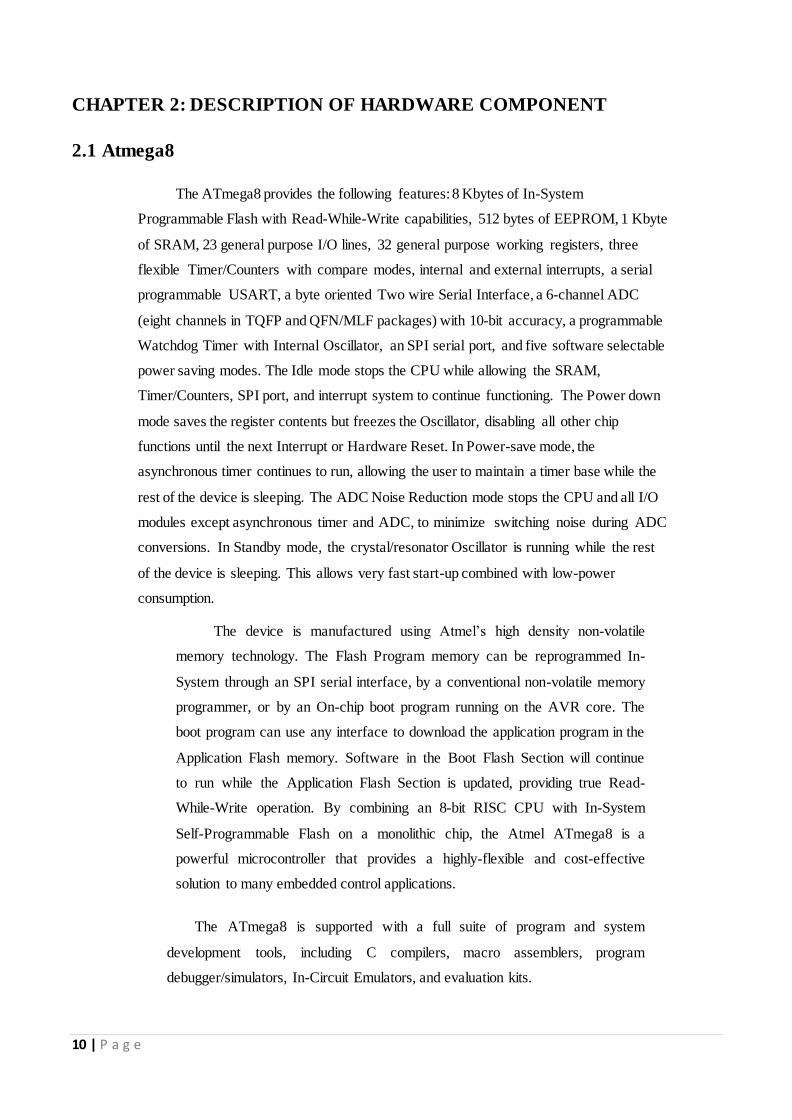
2.1 Atmega8
The ATmega8 provides the following features: 8 Kbytes of In-System
Programmable Flash with Read-While-Write capabilities, 512 bytes of EEPROM, 1 Kbyte
of SRAM, 23 general purpose I/O lines, 32 general purpose working registers, three
flexible Timer/Counters with compare modes, internal and external interrupts, a serial
programmable USART, a byte oriented Two wire Serial Interface, a 6-channel ADC
(eight channels in TQFP and QFN/MLF packages) with 10-bit accuracy, a programmable
Watchdog Timer with Internal Oscillator, an SPI serial port, and five software selectable
power saving modes. The Idle mode stops the CPU while allowing the SRAM,
Timer/Counters, SPI port, and interrupt system to continue functioning. The Power down
mode saves the register contents but freezes the Oscillator, disabling all other chip
functions until the next Interrupt or Hardware Reset. In Power-save mode, the
asynchronous timer continues to run, allowing the user to maintain a timer base while the
rest of the device is sleeping. The ADC Noise Reduction mode stops the CPU and all I/O
modules except asynchronous timer and ADC, to minimize switching noise during ADC
conversions. In Standby mode, the crystal/resonator Oscillator is running while the rest
of the device is sleeping. This allows very fast start-up combined with low-power
consumption.
The device is manufactured using Atmel’s high density non-volatile
memory technology. The Flash Program memory can be reprogrammed In-
System through an SPI serial interface, by a conventional non-volatile memory
programmer, or by an On-chip boot program running on the AVR core. The
boot program can use any interface to download the application program in the
Application Flash memory. Software in the Boot Flash Section will continue
to run while the Application Flash Section is updated, providing true Read-
While-Write operation. By combining an 8-bit RISC CPU with In-System
Self-Programmable Flash on a monolithic chip, the Atmel ATmega8 is a
powerful microcontroller that provides a highly-flexible and cost-effective
solution to many embedded control applications.
The ATmega8 is supported with a full suite of program and system
development tools, including C compilers, macro assemblers, program
debugger/simulators, In-Circuit Emulators, and evaluation kits.

11 | P a g e
Pin diagram

12 | P a g e
Internal architecture:

13 | P a g e

14 | P a g e
Features
• High-performance, Low-power Atmel®AVR® 8-bit Microcontroller • Advanced RISC Architecture
- 130 Powerful Instructions - Most Single-clock Cycle Execution - 32 × 8 General Purpose Working Registers - Fully Static Operation - Up to 16MIPS Throughput at 16MHz - On-chip 2-cycle Multiplier
• High Endurance Non-volatile Memory segments - 8Kbytes of In-System Self-programmable Flash program memory - 512Bytes EEPROM - 1Kbyte Internal SRAM - Write/Erase Cycles: 10,000 Flash/100,000 EEPROM - Data retention: 20 years at 85°C/100 years at 25°C(1)
- Optional Boot Code Section with Independent Lock Bits In-System Programming by On-chip Boot Program True Read-While-Write Operation
- Programming Lock for Software Security

15 | P a g e
• Peripheral Features - Two 8-bit Timer/Counters with Separate Prescaler, one Compare Mode - One 16-bit Timer/Counter with Separate Prescaler, Compare Mode, and Capture
Mode - Real Time Counter with Separate Oscillator - Three PWM Channels - 8-channel ADC in TQFP and QFN/MLF package
Eight Channels 10-bit Accuracy - 6-channel ADC in PDIP package
Six Channels 10-bit Accuracy - Byte-oriented Two-wire Serial Interface - Programmable Serial USART - Master/Slave SPI Serial Interface - Programmable Watchdog Timer with Separate On-chip Oscillator - On-chip Analog Comparator
• Special Microcontroller Features - Power-on Reset and Programmable Brown-out Detection - Internal Calibrated RC Oscillator - External and Internal Interrupt Sources - Five Sleep Modes: Idle, ADC Noise Reduction, Power-save, Power-down, and
Standby • I/O and Packages
- 23 Programmable I/O Lines - 28-lead PDIP, 32-lead TQFP, and 32-pad QFN/MLF
• Operating Voltages - 2.7V - 5.5V (ATmega8L) - 4.5V - 5.5V (ATmega8)
• Speed Grades - 0 - 8MHz (ATmega8L) - 0 - 16MHz (ATmega8)
• Power Consumption at 4Mhz, 3V, 25°C - Active: 3.6mA - Idle Mode: 1.0mA - Power-down Mode: 0.5µA
Atmel
AVR
CPU
Core
Introduction This section discusses the Atmel®AVR® core architecture in general. The main
function of the CPU core is to ensure correct program execution. The CPU must
therefore be able to access memories, perform calculations, control peripherals, and
handle interrupts.

16 | P a g e
Architectural BLOCK DIAGRAM OF AVR MCU ARCHITECTURE
Overview

17 | P a g e
2.2 TRANSFORMER:
A transformer is a device that transfers electrical energy from one circuit to another through inductively
coupled conductors - the transformer's coils or windings. Except for air-core transformers, the conductors are
commonly wound around a single iron-rich core, or around separate but magnetically coupled cores. A
varying current in the first or primary winding creates a varying magnetic field in the core of the transformer.
This varying magnetic field induces a varying electromotive force or voltage in the secondary winding. This
effect is called mutual induction.
Transformer
If a load is connected to the secondary circuit, electric charge will flow in the secondary winding of the
transformer and transfer energy from the primary circuit to the load connected in the secondary circuit. The
secondary induced voltage VS, of an ideal transformer, is scaled from the primary VP by a factor equal to the
ratio of the number of turns of wire in their respective windings:
𝐍𝐬
𝐍𝐩
= 𝐕𝐬
𝐕𝐩
By appropriate selection of the numbers of turns, a transformer thus allows an alternating voltage to be
stepped up - by making NS more than NP or stepped down, by making it.
BASIC PARTS OF A TRANSFORMER
In its most basic form a transformer consists of:
A primary coil or winding.
A secondary coil or winding.
A core that supports the coils or windings.

18 | P a g e
Refer to the transformer circuit in figure as you read the following explanation: The primary winding is
connected to a 50-hertz ac voltage source. The magnetic field builds up and collapses about the primary
winding. The expanding and contracting magnetic field around the primary winding cuts the secondary
winding and induces an alternating voltage into the winding. This voltage causes alternating current to flow
through the load. The voltage may be stepped up or down depending on the design of the primary and
secondary windings.
THE COMPONENTS OF A TRANSFORMER
Two coils of wire are wound on some type of core material. In some cases the coils of wire are wound on a
cylindrical or rectangular cardboard form. In effect, the core material is air and the transformer is called an
air-core transformer. Transformers used at low frequencies, such as 50 hertz and 400 hertz, require a core of
low-reluctance magnetic material, usually iron. This type of transformer is called an iron-core transformer.
Most power transformers are of the iron-core type. The principle parts of a transformer and their functions
are: The core, which provides a path for the magnetic lines of flux. The Primary winding, this receives
energy from the ac source. The secondary winding, this receives energy from the primary winding and
delivers it to the load. The enclosure, this protects the above components from dirt, moisture, and mechanical
damage.
2.3 BRIDGE RECTIFIER
A bridge rectifier makes use of four diodes in a bridge arrangement to achieve full-wave rectification. This is
a widely used configuration, both with individual diodes wired as shown and with single component bridges
where the diode bridge is wired internally.
Basic operation
According to the conventional model of current flow originally established by Benjamin Franklin and still
followed by most engineers today, current is assumed to flow through electrical conductors from the positive
to the negative pole. In actuality, free electrons in a conductor nearly always flow from the negative to the
positive pole. In the vast majority of applications, however, the actual direction of current flow is irrelevant.
Therefore, in the discussion below the conventional model is retained. In the diagrams below, when the input
connected to the left corner of the diamond is positive, and the input connected to the right corner is negative,
current flows from the upper supply terminal to the right along the red(positive) path to the output, and
returns to the lower supply terminal via the blue (negative) path.

19 | P a g e
Bridge rectifier
When the input connected to the left corner is negative, and the input connected to the right corner is
positive, current flows from the lower supply terminal to the right along the red path to the output, and
returns to the upper supply terminal via the blue path.
In each case, the upper right output remains positive and lower right output negative. Since this is true
whether the input is AC or DC, this circuit not only produces a DC output from an AC input, it can also
provide what is sometimes called "reverse polarity protection". That is, it permits normal functioning of DC-
powered equipment when batteries have been installed backwards, or when the leads from a DC power
source have been reversed, and protects the equipment from potential damage caused by reverse polarity.
Prior to availability of integrated electronics, such a bridge rectifier was always constructed from discrete
components. Since about 1950, a single four terminal component containing the four diodes connected in the
bridge configuration became a standard commercial component and is now available with various voltage
and current ratings.
Output smoothing
For many applications, especially with single phase AC where the full-wave bridge serves to convert an AC
input into a DC output, the addition of a capacitor may be desired because the bridge alone supplies an output
of fixed polarity but continuously varying or pulsating magnitude.

20 | P a g e
Bridge rectifier in parallel capacitor at the output
The function of this capacitor, known as a reservoir capacitor is to lessen the variation in the rectified AC
output voltage waveform from the bridge. One explanation of smoothing is that the capacitor provides a low
impedance path to the AC component of the output, reducing the AC voltage across, and AC current through,
the resistive load. In less technical terms, any drop in the output voltage and current of the bridge tends to be
cancelled by loss of charge in the capacitor. This charge flows out as additional current through the load.
Thus the change of load current and voltage is reduced relative to what would occur without the capacitor.
Increases of voltage correspondingly store excess charge in the capacitor, thus moderating the change in
output voltage / current. The simplified circuit shown has a well-deserved reputation for being dangerous,
because, in some applications, the capacitor can retain a lethal charge after the AC power source is removed.
If supplying a dangerous voltage, a practical circuit should include a reliable way to safely discharge the
capacitor. If the normal load cannot be guaranteed to perform this function, perhaps because it can be
disconnected, the circuit should include a bleeder resistor connected as close as practical across the capacitor.
This resistor should consume a current large enough to discharge the capacitor in a reasonable time, but small
enough to minimize unnecessary power waste. Because a bleeder sets a minimum current drain, the
regulation of the circuit, defined as percentage voltage change from minimum to maximum load, is
improved. However in many cases the improvement is of in significant magnitude. capacitor and the load
resistance have a typical time constant τ = RC where C and R are the capacitance and load resistance
respectively. As long as the load resistor is large enough so that this time constant is much longer than the
time of one ripple cycle, the above configuration will produce a smoothed DC voltage across the load.
In some designs, a series resistor at the load side of the capacitor is added. The smoothing can then be
improved by adding additional stages of capacitor–resistor pairs, often done only for sub-supplies to critical
high-gain circuits that tend to be sensitive to supply voltage noise. The idealized waveforms shown above are
seen for both voltage and current when the load on the bridge is resistive. When the load includes a
smoothing capacitor, both the voltage and the current waveforms will be greatly changed. While the voltage

21 | P a g e
is smoothed, as described above, current will flow through the bridge only during the time when the input
voltage is greater than the capacitor voltage. For example, if the load draws an average current of n Amps,
and the diodes conduct for 10% of the time, the average diode current during conduction must be 10n Amps.
This non-sinusoidal current leads to harmonic distortion and a poor power factor in the AC supply. In a
practical circuit, when a capacitor is directly connected to the output of abridge, the bridge diodes must be
sized to withstand the current surge that occurs when the power is turned on at the peak of the AC voltage
and the capacitor is fully discharged. Sometimes a small series resistor is included before the capacitor to
limit this current, though in most applications the power supply transformer's resistance is already sufficient.
Output can also be smoothed using a choke and second capacitor. The choke tends to keep the current rather
than the voltage more constant. Due to the relatively high cost of an effective choke compared to a resistor
and capacitor this is not employed in modern equipment.
2.4 REGULATOR IC
It is a three pin IC used as a voltage regulator. It converts unregulated DC current into regulated DC current.
First pin is used for input, second for ground and third pin gives the rectified and filtered output. It has an
inbuilt filtering circuit which removes the ripples present in the rectified DC obtained from full bridge
rectifier circuit.
MCT7805CT voltage regulator

22 | P a g e
Normally we get fixed output by connecting the voltage regulator at the output of the filtered DC see in
above diagram. It can also be used in circuits to get a low DC voltage from a high DC voltage for example
we use 7805 to get 5V from 12V. There are two types of voltage regulators 1. fixed voltage regulators 78xx,
79xx 2. Variable voltage regulators in fixed voltage regulators there is another classification 1. + ve voltage
regulators 2.–vevoltage regulators positive voltage regulators this include 78xx voltage regulators. The most
commonly used ones are 7805 and 7812. 7805 gives fixed 5V DC voltage if input voltage is in 7.5V, 20V.
7805 is a voltage regulator integrated circuit. It is a member of 78xx series of fixed linear voltage regulator
ICs. The voltage source in a circuit may have fluctuations and would not give the fixed voltage output. The
voltage regulator IC maintains the output voltage at a constant value. The xx in 78xx indicates the fixed
output voltage it is designed to provide. 7805 provides +5V regulated power supply. Capacitors of suitable
values can be connected at input and output pins depending upon the respective voltage levels.
2.5 Solar Tracker
Solar Tracker is basically a device onto which solar panels are fitted which tracks the motion of the sun
across the sky ensuring that the maximum amount of sunlight strikes the panels throughout the day. After
finding the sunlight, the tracker will try to navigate through the path ensuring the best sunlight is detected.
The design of the Solar Tracker requires many components. The design and construction of it could be
divided into six main parts that would need to work together harmoniously to achieve a smooth run for the
Solar Tracker, each with their main function. They are:
Methods of Tracker Mount
Methods of Drives
Sensor and Sensor Controller
Motor and Motor Controller
Tracker Solving Algorithm
Data Acquisition/Interface Card
2.6 Methods of Tracker Mount
1. Single axis solar trackers
Single axis solar trackers can either have a horizontal or a vertical axle. The horizontal type is used in
tropical regions where the sun gets very high at noon, but the days are short. The vertical type is used in high
latitudes where the sun does not get very high, but summer days can be very long. The single axis tracking
system is the simplest solution and the most common one used.

23 | P a g e
2. Double axis solar trackers
Double axis solar trackers have both a horizontal and a vertical axle and so can track the Sun's apparent
motion exactly anywhere in the World. This type of system is used to control astronomical telescopes, and so
there is plenty of software available to automatically predict and track the motion of the sun across the sky.
By tracking the sun, the efficiency of the solar panels can be increased by 30-40%.The dual axis tracking
system is also used for concentrating a solar reflector toward the concentrator on heliostat systems.
2.7 Methods of Drive
1. Active Trackers
Active Trackers use motors and gear trains to direct the tracker as commanded by a controller responding
to the solar direction. Light-sensing trackers typically have two photo sensors, such as photodiodes,
configured differentially so that they output a null when receiving the same light flux. Mechanically, they
should be omnidirectional and are aimed 90 degrees apart. This will cause the steepest part of their cosine
transfer functions to balance at the steepest part, which translates into maximum sensitivity.
2. Passive Trackers
Passive Trackers use a low boiling point compressed gas fluid that is driven to one side or the other by solar
heat creating gas pressure to cause the tracker to move in response to an imbalance.
2.8 Sensors
A sensor is a device that measures a physical quantity and converts it into a signal which can be read by an
observer or by an instrument.
1. Light Dependent Resistor
Light Dependent Resistor is made of a high-resistance semiconductor. It can also be referred to as a
photoconductor. If light falling on the device is of the high enough frequency, photons absorbed by the
semiconductor give bound electrons enough energy to jump into the conduction band. The resulting free
electron conducts electricity, thereby lowering resistance. Hence, Light Dependent Resistors is very useful in
light sensor circuits. LDR is very high-resistance, sometimes as high as 10MΩ, when they are illuminated
with light resistance drops dramatically.

24 | P a g e
A Light Dependent Resistor is a resistor that changes in value according to the light falling on it. A
commonly used device, the ORP-12, has a high resistance in the dark, and a low resistance in the light.
Connecting the LDR to the microcontroller is very straight forward, but some software ‘calibrating’ is
required. It should be remembered that the LDR response is not linear, and so the readings will not change in
exactly the same way as with a potentiometer. In general there is a larger resistance change at brighter light
levels. This can be compensated for in the software by using a smaller range at darker light levels.
Fig 4.1 Light Dependent Resistor
2. Photodiode
Photodiode is a light sensor which has a high speed and high sensitive silicon PIN photodiode in a
miniature flat plastic package. A photodiode is designed to be responsive to optical input. Due to its water
clear epoxy the device is sensitive to visible and infrared radiation. The large active area combined with a flat
case gives a high sensitivity at a wide viewing angle. Photodiodes can be used in either zero bias or reverse
bias. In zero bias, light falling on the diode causes a voltage to develop across the device, leading to a current
in the forward bias direction. This is called the photovoltaic effect, and is the basis for solar cells - in fact a
solar cell is just a large number of big, cheap photodiodes. Diodes usually have extremely high resistance
when reverse biased. This resistance is reduced when light of an appropriate frequency shines on the
junction. Hence, a reverse biased diode can be used as a detector by monitoring the current running through
it. Circuits based on this effect are more sensitive to light than ones based on the photovoltaic effect.

25 | P a g e
different type of photo diodes
2.9 Motor
Motor is use to drive the Solar Tracker to the best angle of exposure of light. For this section, we are using
stepper motor.
Stepper Motor
Features
Linear speed control of stepper motor
Control of acceleration, deceleration, max speed and number of steps to move
Driven by one timer interrupt
Full - or half-stepping driving mode
Supports all AVR devices with 16bit timer
Introduction
This application note describes how to implement an exact linear speed controller for stepper motors. The
stepper motor is an electromagnetic device that converts digital pulses into mechanical shaft rotation. Many
advantages are achieved using this kind of motors, such as higher simplicity, since no brushes or contacts are
present, low cost, high reliability, high torque at low speeds, and high accuracy of motion. Many systems
with stepper motors need to control the acceleration/deceleration when changing the speed. This application
note presents a driver with a demo application, capable of controlling acceleration as well as position and
speed.

26 | P a g e
Fig 4.3 Stepper Motors
Theory
Stepper motor
This application note covers the theory about linear speed ramp stepper motor control as well as the
realization of the controller itself. It is assumed that the reader is familiar with basic stepper motor operation,
but a summary of the most relevant topics will be given.
Bipolar vs. Unipolar stepper motors
The two common types of stepper motors are the bipolar motor and the Unipolar motor. The bipolar and
unipolar motors are similar, except that the Unipolar has a centre tap on each winding as shown in Figure 4.4

27 | P a g e
Fig 4.4 Bipolar and Unipolar stepper Motor
Unipolar stepper motor
Stepper motors are very accurate motors that are commonly used in computer disk drives, printers and
clocks. Unlike dc motors, which spin round freely when power is applied, stepper motors require that their
power supply be continuously pulsed in specific patterns. For each pulse the stepper motor moves around one
step often 15 degrees giving 24 steps in a full revolution.There are two main types of stepper motors -
Unipolar and Bipolar. Unipolar motors usually have four coils which are switched on and off in a particular
sequence. Bipolar motors have two coils in which the current flow is reversed in a similar sequence. Each of
the four coils in a Unipolar stepper motor must be switched on and off in a certain order to make the motor
turn. Many microprocessor systems use four output lines to control the stepper motor, each output line
controlling the power to one of the coils. As the stepper motor operates at 5V, the standard transistor circuit
is required to switch each coil. As the coils create a back emf when switched off, a suppression diode on each
coil is also required. The table below show the four different steps required to make the motor turn.
Table 4.1 Unipolar stepper motor operation
Step Coil 1 Coil 2 Coil 3 Coil 4
1 1 0 1 0
2 1 0 0 1
3 0 1 0 1
4 0 1 1 0
1 1 0 1 0

28 | P a g e
Look carefully at the table 4.1 and notice that a pattern is visible. Coil 2 is always the opposite or logical
NOT of coil 1. The same applies for coils 3 and 4. It is therefore possible to cut down the number of
microcontroller pins required to just two by the use of two additional NOT gates. Fortunately the Darlington
driver IC ULN2003 can be used to provide both the NOT and Darlington driver circuits. It also contains the
back emf suppression diodes so no external diodes are required.
Bipolar Stepper motor
The bipolar stepper motor has two coils that must be controlled so that the current flows in different
directions through the coils in a certain order. The changing magnetic fields that these coils create cause the
rotor of the motor to move around in steps.
The bipolar motor needs current to be driven in both directions through the windings, and a full bridge driver
is needed as shown in Figure 4.5 (a). The centre tap on the Unipolar motor allows a simpler driving circuit
shown in Figure 4.5 (b), limiting the current flow to one direction. The main drawback with the Unipolar
motor is the limited capability to energize all windings at any time, resulting in a lower torque compared to
the bipolar motor. The Unipolar stepper motor can be used as a bipolar motor by disconnecting the centre
tap.
(a) (b)
Fig - Bipolar and Unipolar drivers with MOS transistors

29 | P a g e
Implementation
A working implementation written in C is included with this application note. Full documentation of the
source code and compilation information is found by opening the ‘readme.html’ file included with the source
code. The demo application demonstrates linear speed control of a stepper motor. The user can control the
stepper motor speed profile by issuing different commands using the serial port, and the AVR will drive the
connected stepper motor accordingly. The demo application is divided in three major blocks, as shown in the
block diagram in Figure 4.6. There is one file for each block and also a file for UART routines used by the
main routine.
Fig 4.6 Block diagram of demo application
Main c has a menu and a command interface, giving the user control of the stepper motor by a terminal
connected to the serial line. Speed controller c calculates the needed data and generates step pulses to make
the stepper motor follow the desired speed profile. Smdriver.c counts the steps and outputs the correct signals
to control the stepper motor.
Timer interrupt
The timer interrupt generates the step pulses calls the function Step Counter ( ) and is only running when the
stepper motor is moving. The timer interrupt will operate in four different states according to the speed
profile shown in Figure 4.7 and this behaviour is realized with a state machine in the timer interrupt shown in
Figure 4.8.
Fig 4.7 Operating states for different speed profile parts

30 | P a g e
Fig 4.8 State machine for timer interrupt
When the application starts or when the stepper motor is stopped the state-machine remains in the state
STOP. When setup calculations are done, a new state is set and the timer interrupt is enabled. When moving
more than one step the state-machine goes to ACCEL. If moving only 1 step, the state is changed to DECEL.
When the state is changed to ACCEL, the application accelerates the stepper motor until either the desired
speed is reached and the state is changed to RUN, or deceleration must start, changing the state to DECEL.
When the state is set to RUN, the stepper motor is kept at constant speed until deceleration must start, then
the state is changed to DECEL.It will stay in DECEL and decelerate until the speed reaches zero desired
number of steps. The state is then changed to STOP.
2.10 Microcontroller
A microcontroller is a single chip that contains the processor, non-volatile memory for the program, volatile
memory for input and output, a clock and an I/O control unit also called a computer on a chip, billions of
microcontroller units are embedded each year in a myriad of products from toys to appliances to automobiles.
For example, a single vehicle can use 70 or more microcontrollers. The following picture describes a general
block diagram of microcontroller.
Features
High-performance, Low-power AVR 8-bit Microcontroller
Advanced RISC Architecture
131 Powerful Instructions – Most Single-clock Cycle Execution
32 x 8 General Purpose Working Registers
Fully Static Operation

31 | P a g e
Up to 16 MIPS Throughput at 16 MHz
On-chip 2-cycle Multiplier
High Endurance Non-volatile Memory segments
16K Bytes of In-System Self-programmable Flash program memory
512 Bytes EEPROM
1K Byte Internal SRAM
Write/Erase Cycles: 10,000 Flash/100,000 EEPROM
Data retention: 20 years at 85°C/100 years at 25°C
Optional Boot Code Section with Independent Lock Bits
In-System Programming by On-chip Boot Program
True Read-While-Write Operation
Programming Lock for Software Security
JTAG Interface
Boundary-scan Capabilities According to the JTAG Standard
Extensive On-chip Debug Support
Programming of Flash, EEPROM, Fuses, and Lock Bits through the JTAG Interface
Peripheral Features
Two 8-bit Timer/Counters with Separate Prescalers and Compare Modes
One 16-bit Timer/Counter with Separate Prescalers, Compare Mode, and Capture
Mode
Real Time Counter with Separate Oscillator
Four PWM Channels
8-channel, 10-bit ADC
8 Single-ended Channels
7 Differential Channels in TQFP Package Only
2 Differential Channels with Programmable Gain at 1x, 10x, or 200x
Byte-oriented Two-wire Serial Interface
Programmable Serial USART
Master/Slave SPI Serial Interface
Programmable Watchdog Timer with Separate On-chip Oscillator
On-chip Analog Comparator
Special Microcontroller Features
Power-on Reset and Programmable Brown-out Detection

32 | P a g e
Internal Calibrated RC Oscillator
External and Internal Interrupt Sources
Six Sleep Modes: Idle, ADC Noise Reduction, Power-save, Power-down, Standby
and Extended Standby
I/O and Packages
32 Programmable I/O Lines
40-pin PDIP, 44-lead TQFP, and 44-pad QFN/MLF
Operating Voltages
2.7 - 5.5V for ATmega16L
4.5 - 5.5V for ATmega16
Speed Grades
0 - 8 MHz for ATmega16L
0 - 16 MHz for ATmega16
Power Consumption @ 1 MHz, 3V, and 25°C for ATmega16L
Active: 1.1 mA
Idle Mode: 0.35 mA
Power-down Mode: < 1 μA

33 | P a g e
CHAPTER 3 :CIRCUITS AND THEIR OPERATION
3.1 Technology of Solar Panel
Solar panels are devices that convert light into electricity. They are called solar after the sun because the sun
is the most powerful source of the light available for use. They are sometimes called photovoltaic which
means "light-electricity". Solar cells or PV cells rely on the photovoltaic effect to absorb the energy of the
sun and cause current to flow between two oppositely charge layers. A solar panel is a collection of solar
cells. Although each solar cell provides a relatively small amount of power, many solar cells spread over a
large area can provide enough power to be useful. To get the most power, solar panels have to be pointed
directly at the Sun. The development of solar cell technology begins with 1839 research of French physicist
Antoine-Cesar Becquerel. He observed the photovoltaic effect while experimenting with a solid electrode in
an electrolyte solution. After that he saw a voltage developed when light fell upon the electrode.
According to Encyclopaedia Britannica the first genuine for solar panel was built around 1883 by Charles
Fritts. He used junctions formed by coating selenium (a semiconductor) with an extremely thin layer of gold.
Crystalline silicon and gallium arsenide are typical choices of materials for solar panels. Gallium arsenide
crystals are grown especially for photovoltaic use, but silicon crystals are available in less-expensive standard
ingots, which are produced mainly for consumption in the microelectronics industry. Norway’s Renewable
Energy Corporation has confirmed that it will build a solar manufacturing plant in Singapore by 2010 - the
largest in the world. This plant will be able to produce products that can generate up to 1.5 Giga watts of
energy every year. That is enough to power several million households at any one time. Last year the world
as a whole produced products that could generate just 2 GW in total.
3.2 Evolution of Solar Tracker
Since the sun moves across the sky throughout the day, in order to receive the best angle of exposure to
sunlight for collection energy. A tracking mechanism is often incorporated into the solar arrays to keep the
array pointed towards the sun. A solar tracker is a device onto which solar panels are fitted which tracks the
motion of the sun across the sky ensuring that the maximum amount of sunlight strikes the panels throughout
the day. When compare to the price of the PV solar panels, the cost of a solar tracker is relatively low. Most
photovoltaic solar panels are fitted in a fixed location- for example on the sloping roof of a house, or on
framework fixed to the ground. Since the sun moves across the sky though the day, this is far from an ideal
solution. Solar panels are usually set up to be in full direct sunshine at the middle of the day facing South in

34 | P a g e
the Northern Hemisphere, or North in the Southern Hemisphere. Therefore morning and evening sunlight hits
the panels at an acute angle reducing the total amount of electricity which can be generated each day.
Fig - Sun’s apparent motion
During the day the sun appears to move across the sky from left to right and up and down above the
horizon from sunrise to noon to sunset. Figure 2.1 shows the schematic above of the Sun's apparent
motion as seen from the Northern Hemisphere. To keep up with other green energies, the solar cell
market has to be as efficient as possible in order not to lose market shares on the global energy
marketplace. The end-user will prefer the tracking solution rather than a fixed ground system to increase
their earnings because:
The efficiency increases by 30-40%.
The space requirement for a solar park is reduced, and they keep the same output.
The return of the investment timeline is reduced.
The tracking system amortizes itself within 4 years.
In terms of cost per Watt of the completed solar system, it is usually cheaper to use a solar
tracker and less solar panels where space and planning permit.
A good solar tracker can typically lead to an increase in electricity generation capacity of 30-
50%.

35 | P a g e
3.3 Project Description
3.3.1 Block Diagram
Block Diagram of Project

36 | P a g e
3.3.2 Schematic Diagram
Schematic Diagram of Project
3.3.3 PRINTED CIRCUIT BOARD
Almost all circuits encountered on electronic equipment (computers, TV, radio, industrial control equipment,
etc.) are mounted on printed circuit boards. Close inspection of a PCB reveals that it contains a series of
copper tracks printed on one or both sides of a fiber glass board. The copper tracks form the wiring pattern
required to link the circuit devices according to a given circuit diagram. Hence, to construct a circuit the
necessity of connecting insulated wires between components is eliminated, resulting in a cleaner arrangement
and providing mechanical support for components. Moreover, the copper tracks are highly conductive and
the whole PCB can be easily reproduced for mass production with increased reliability.
1) Types of PCB
PCB's can be divided into three main categories:
Single-sided
Double-sided
Multi-layered.

37 | P a g e
Single-sided PCB
A single-sided PCB contains copper tracks on one side of the board only, as shown in Figure 3.3. Holes are
drilled at appropriate points on the track-so that each component can be inserted from the non-copper side of
the board, as shown in Figure 3.4. Each pin is then soldered to the copper track.
Printed circuit board
Single sided PCB Double-sided PCB
Double-sided PCBs have copper tracks on both sides of the board. The track layout is designed so as not to
allow shorts from one side to another, if it is required to link points between the two sides, electrical
connections are made by small interconnecting holes which are plated with copper during manufacture.

38 | P a g e
Double sided PCB Multi-layer PCB
In multi-layer PCBs, each side contains several layers of track patterns which are insulated from one another.
These layers are laminated under heat and high pressure. A multi-layer PCB is shown in Figure 3.6
Multi layered PCB 2) MAKING A PCB
PCB's commonly available on the market are not particular circuits, but are available as copper clad boards.
In other words, the whole area of one or both sides of the board is coated with copper. The user then draws
his track layout on the copper surface, according to his circuit diagram. Next, the untraced copper area
removed by a process called etching. Here, the unused copper area is dissolved away by an etching solution
and only the required copper tracks remain. The board is then cleaned and drilled at points where each device
is to be inserted. Finally, each component is soldered to the board.
The etching process depends on whether board is of plain or photo-resist type. These are treated separately in
the following section.

39 | P a g e
a) Making a PCB out of a plain copper clad board
Equipment required
The following items are required:
A single-sided copper clad board.
Ferric chloride solution, which is the etching liquid.
An etch-resist pen is with its ink resisting to ferric chloride.
A PCB eraser.
Track layout design
The first step is to draw the track layout on the plain copper clad board, according to the circuit to be
implemented which turns on an LED when the push-button is pressed. The lines joining different
components will form the track layout on the PCB. Each component is inserted from the non-copper side of
the board and its leads appear on the copper side. For example, when viewing the component side, the base
of the BC109 transistor appears to the right of the collector, while from the track side, it appears at the left of
the collector.
b) Making a PCB out of a photo resist board
Equipment required
Photo-resist board
Ferric chloride solution as etchant
A white board marker
Transparent polyester film for use as drafting sheet
Sodium hydroxide solution as developer
Ultra-violet exposure unit
Track layout design
Using the same principles outlined in section a track layout is drawn to scale on the transparency using the
white board' marker. It may be useful to insert graph paper below the transparent sheet for accurate
dimensioning of the layout.
Photo-etching
The principle behind photo-etching is to place the transparency over the copper clad and to expose it to UV
radiation, hence leaving the track regions intact and softening unused areas. First, the protective plastic film

40 | P a g e
is removed from the board. The traced transparency is then placed over the board, being careful to ensure that
the copper side of the design faces upwards. The combination is next placed in a UV exposure unit, with the
transparency facing the fluorescent tubes inside the unit. At the track regions, UV radiation is prevented from
reaching the board, and hence the photo sensitive remains hardened in these regions. After an exposure of
about 5 minutes the board can be removed. The PCB is then placed in a solution of caustic soda which
dissolves away any unhardened photo-sensitive area. After a few minutes of development time, the track
layout is apparent. The board is finally removed and rinsed in cold water.
Final etching
After having allowed the tracks to harden for about half an hour, the unmarked copper area is etched by ferric
chloride solution.
3) The following points should be noted:
It is a good idea to draft the track layout on graph paper before drawing the final layout on the copper
clad.
Use an etch resist pen to draw the track layout on the copper clad (the latter must be cleaned initially).
The following lead spacing can be used as a rule of thumb: allow 10 mm for a 1/4 W resistor, 8 mm
for a signal diode, 4 mm for LED's and ceramic capacitors. The lead spacing may also be measured
before drawing.
Terminals for the power supply input leads must also be included on the layout.
The arrangement of components must be well planned so as to minimize the amount of cooper clad
board required.
Allow the ink to dry before etching.
4) Etching
The copper clad is now ready to be etched. If the etchant is available in powder form, it needs to be mixed
with water in anon-corrodible container. A powder to water ratio of 2:5 by mass is about right. Etching time
may vary between 10 to as long as 90 minutes, depending on the concentration and temperature of the
etchant. The process can be accelerated by warming the solution and by frequently agitating the etching bath.
The ferric chloride solution gradually dissolves any untraced copper area. When etching is complete, only the

41 | P a g e
track layout remains on the board. The latter is then removed the bath and rinsed with clean water. The etch
resist ink is finally rubbed away with a PCB eraser, or with very fine grain sand paper.
Making a PCB out of a photo-resist copper clad board
The photo-resist board consists of a single or double sided copper clad coated with a light-sensitive and the
latter is protected with a plastic which should be removed before use. Its advantage over the plain copper clad
board is that the track layout does not need to be drawn directly on the board.
The use of etch-resist transfers
The use of pens to design track layouts may not give neat result, even when using a ruler. For instance, it
may be difficult to draw tracks with the same line Width or to draw well aligned terminals for IC's and
discrete devices, Etch-resist PCB symbols and tracks are available for direct transfer to the copper clad or to
the transparency. Transfer is by rubbing down the relevant symbol with a soft pencil.

42 | P a g e
CHAPTER 4: SOFTWARE DEVELOPMENT
4.1 FLOWCHART

43 | P a g e
CHAPTER 5 : RESULTS & CONCLUSION
APPLICATIONS
Used in satellites as source of fuel.
Used in solar thermal collector to collect heat.
Used in water heaters.
Used in heat extinguishers.
Used in solar power plants.
Used in inverters[AC-DC].
Used in solar water pumps.
Advantages
The advantage of this unit is that to run the system it does not need computer.
Solar cells directly convert the solar radiation into electricity using photovoltaic effect without going through a
thermal process.
During the winter the sun has a low position, tracking angle from sunrise to sunset is shortened.

44 | P a g e
Limitations
Using this system at a time we can control only one solar panel.
Higher hardware expenditure.
Weather condition can affect the system.
CONCLUSION
From the design of experimental set up with Micro Controller Based Solar Tracking System Using Stepper
Motor If we compare Tracking by the use of LDR with Fixed Solar Panel System we found that the
efficiency of Micro Controller Based Solar Tracking System is improved by 30-45% and it was found that all
the parts of the experimental setup are giving good results. The required Power is used to run the motor by
using Step-Down T/F by using 220V AC. Moreover, this tracking system does track the sun in a continuous
manner. And this system is more efficient and cost effective in long run. From the results it is found that, by
automatic tracking system, there is 30 % gain in increase of efficiency when compared with non-tracking
system. The solar tracker can be still enhanced additional features like rain protection and wind protection
which can be done as future work.

45 | P a g e
REFERENCES
[1] Rizk J. and Chaiko Y. “Solar Tracking System: More Efficient Use of Solar Panels”, World Academy of
Science, Engineering and Technology 41 2008.
[2] Filfil Ahmed Nasir, Mohussen Deia Halboot, Dr. Zidan Khamis A. “Microcontroller-Based Sun Path
Tracking System”, Eng. & Tech. Journal, Vol. 29, No.7, 2011.
[3] Alimazidi Mohammad, Gillispie J, Mazidi, Rolin D. McKinlay, “The 8051 Microcontroller and
Embedded Systems”, An imprint of Pearson Education.
[4] Mehta V K, Mehta Rohit, “Principles of Electronics”, S. Chand & Company Ltd.
[5] Balagurusamy E, “Programming in ANSI C”, Tata McGraw-Hill Publishing Company Limited.
[6] Damm, J. Issue #17, June/July 1990. An active solar tracking system, Home Brew Magazine.
[7] Koyuncu B and Balasubramanian K, “A microprocessor controlled automatic sun tracker,” IEEE Trans.
Consumer Electron., vol. 37, no. 4,pp. 913-917, 1991.
[8] Konar A and Mandal A K, “Microprocessor based automatic sun tracker,” IEE Proc. Sci., Meas.
Technol., vol. 138, no. 4, pp. 237-241,1991.