Project Report
54
Bit Error Rate Performance Analysis of a Modern Channel Codec in Gaussian Channel Using Higher Modulation Schemes.
-
Upload
olufisayo-adekile -
Category
Documents
-
view
15 -
download
0
Transcript of Project Report
Bit Error Rate Performance Analysis of a Modern Channel Codec in Gaussian Channel Using Higher Modulation Schemes.

Bit Error Rate Performance Analysis of a Modern Channel Codec in Gaussian Channel Using Higher Modulation Schemes.

Bit Error Rate Performance Analysis of a Modern Channel Codec in Gaussian Channel Using Higher Modulation Schemes.
ACKNOWLEDGEMENT
I indebted to my supervisor Dr Li X Zhang and wish to express my heartfelt gratitude to her
for supervising and directing me all through the duration of this work. Her helpful comments
and suggestions as well as her critical reviews will not be forgotten. I am most grateful to my
accessor Mohsen Razavi for assisting and encouraging me all the way. Lastly I also wish to
thank all the students who helped me in some way or the other, I am very greatful.

Bit Error Rate Performance Analysis of a Modern Channel Codec in Gaussian Channel Using Higher Modulation Schemes.
ABSTRACT
The evolutions of wireless communication systems and networks in recent years have been
explosive.
In this work, the performance of a wireless communication system is investigated. This is
done by analysing the bit error rate performance of a modern channel codec in Gaussian
channel using higher modulation schemes. Also, the bit error rate performance for the
simulated and theoretical results of digitally modulated communication channels was
evaluated compared and analysed along with the use of a convolutional encoder.
Furthermore, this report investigates an advanced algorithm called soft output Viterbi
algorithm which is used in the decoding of the convolutionally encoded bits. Modulation
schemes such as BPSK, QPSK, 16-QAM and 64-QAM are used. Large coding gains were
observed with the use of a convolutional encoder in comparison to the uncoded system, with
as much as 4dB coding gain recorded in the QPSK system with convolutional code over the
uncoded system. Simulation and theoretical results of the various modulation schemes used
are presented.

Bit Error Rate Performance Analysis of a Modern Channel Codec in Gaussian Channel Using Higher Modulation Schemes.
LIST OF FIGURES AND TABLES
FIGURES
Fig 1-3: Block Diagram of a Digital Communication System
Fig 2-1: Block diagram for a communication link
Fig 4-1: Constellation Diagram for BPSK Modulation Scheme
Fig 4-2: Theoretical and Simulated BER against SNR in AWGN for BPSK
Fig 4-3: Constellation Diagram for QPSK Modulation Scheme
Fig 4-4: Theoretical and Simulated BER against SNR in AWGN for QPSK
Fig 4-5: Constellation Diagram for 16 QAM Modulation Scheme
Fig 4-6: Theoretical and Simulated BER against SNR for 16 QAM in AWGN
Fig 4-7: Constellation Diagram for 64 QAM
Fig 4-8: Theoretical and Simulated BER against SNR for 64 QAM
Fig 5-1: BPSK with Convolutional Code and theoretical and Simulated BER against SNR in
AWGN
Fig 5-2: QPSK with Convolutional Code and theoretical and Simulated BER against SNR in
AWGN
Fig 5-3: 16QAM with Convolutional Code and theoretical and Simulated BER against SNR in
AWGN
Fig 5-4: 64QAM with Convolutional Code and theoretical and Simulated BER against SNR in
AWGN

Bit Error Rate Performance Analysis of a Modern Channel Codec in Gaussian Channel Using Higher Modulation Schemes.
TABLE
Table 4-1: Constellation Mapping for 16 QAM
LIST OF ABBREVIATIONS AND SYMBOLS
Abbreviations
ADC Analogue to Digital Converter
AM Amplitude Modulation
ASK Amplitude Shift Key
AWGN Additive White Gaussian Noise
b/s bits per second
BER Bit Error Rate
BPSK Binary Phase-Shift Key
CW Continuous-Wave
DAC Digital to Analogue Converter
dB Decibels
DC Direct Current
DCS Digital Communication System
FM Frequency Modulation
FSK Frequency Shift Key
Hz Hertz
IF Intermediate Frequency
ISI Intersymbol Interference
MLD Maximum Likelihood Decoding
PM Phase Modulation
PSK Phase Shift Keying
RF Radio Frequency
RSC Recursive Systematic Convolutional code.

Bit Error Rate Performance Analysis of a Modern Channel Codec in Gaussian Channel Using Higher Modulation Schemes.
QPSK Quadrature Phase-Shift Key
16QAM 16 Quadrature Amplitude Modulation
64QAM 64 Quadrature Amplitude Modulation
SNR Signal-to-Noise Ratio
TCM Trellis Coded Modulation
Bit Error Rate Performance Analysis of a Modern Channel Codec in Gaussian Channel Using Higher Modulation Schemes.
Table of Contents ACKNOWLEDGEMENT ......................................................................................................... 3
ABSTRACT ............................................................................................................................... 4
LIST OF FIGURES AND TABLES ......................................................................................... 5
LIST OF ABBREVIATIONS AND SYMBOLS ...................................................................... 6
1. INTRODUCTION ............................................................................................................... 10
1.1 Evolution of Communication ......................................................................................... 10
1.2 Digital Communication .................................................................................................. 11
1.3 Fundamentals of Digital Communication ...................................................................... 12
1.4 Project Objectives .......................................................................................................... 13
1.5 Report Structure ............................................................................................................. 15
2. PROCESS DESIGN ............................................................................................................ 15
2.1 Block Diagram ............................................................................................................... 15
3. CHANNEL MODEL ........................................................................................................... 16
3.1 Additive White Gaussian Noise ..................................................................................... 16
3.2 Channel Capacity ........................................................................................................... 18
4. MODULATION SCHEMES ............................................................................................... 18
4.1 Modulation Overview .................................................................................................... 18
4.2 Detection and Demodulation .......................................................................................... 20
4.3 PSK Modulation Scheme ............................................................................................... 21
4.3.1 BPSK Modulation Scheme ...................................................................................... 21
4.3.2 QPSK Modulation Schemes .................................................................................... 23
4.4 Quadrature Amplitude Modulation ................................................................................ 25
4.4.1 16 QAM ................................................................................................................... 27
4.4.2 64 QAM ................................................................................................................... 29
Bit Error Rate Performance Analysis of a Modern Channel Codec in Gaussian Channel Using Higher Modulation Schemes.
4.5 Comparisons of BER in AWGN for Different Modulation Schemes ............................ 31
5. CHANNEL ENCODING ..................................................................................................... 32
5.1 Overview of Channel Coding ......................................................................................... 32
5.2 Convolutional Coding .................................................................................................... 32
5.3 Viterbi Decoding Algorithm .......................................................................................... 35
5.4 Modulation Schemes with Convolutional Code ............................................................. 36
5.5 Discussion of results ...................................................................................................... 40
6. CONCLUSION ................................................................................................................... 40
References ................................................................................................................................ 42
Bibliography ............................................................................................................................ 45
APPENDIX A : UNCODED BPSK SIMULATION OVER AWGN ..................................... 46
APPENDIX B: UNCODED QPSK SIMULATION OVER AWGN ...................................... 47
APPENDIX C: UNCODED 16QAM IN AWGN ................................................................. 49
APPENDIX D: UNCODED 64QAM IN AWGN ................................................................... 51
APPENDIX E: CODED BPSK IN AWGN ............................................................................. 53

Bit Error Rate Performance Analysis of a Modern Channel Codec in Gaussian Channel Using Higher Modulation Schemes.
1. INTRODUCTION
1.1 Evolution of Communication
Communication fundamentally described as the transmission of information from one point
to another, has been an important source in the rapid development of the world today. The
radical growth of the wireless communication segment of the communication industry has not
only captured the attention of the public but also that of the media.
In ancient times, information was transmitted wirelessly through the use of signals such as
smoke signals, flag signals, signal flares or torch signals. To convey these messages over
long distances, observation stations were built on hilltops and along roads and the messages
were passed from station to station. Overtime, these forms of communication began to
evolve.
The advancement into modern communication systems came in form of the telegraph
developed by Samuel Morse in 1837. This brought about a complete revolution in long-
distance communications when the words “What hath God wrought” were transmitted by
Morse’s telegraph between Washington D.C. and Baltimore, Maryland in 1844. The
invention of the telephone in 1875 by Alexander Graham Bell brought about further
improvements in communication systems. He illustrated the possibility of real-time
transmission of speech by electrical encoding and replication of sound with his invention.
Bit Error Rate Performance Analysis of a Modern Channel Codec in Gaussian Channel Using Higher Modulation Schemes.
This paved way for many other inventors as in 1864, James Clerk Maxwell predicted the
existence of radio waves and Heinrich Hertz went on to experimentally established the
existence of radio waves in 1887. Oliver Lodge demonstrated the possibility of wireless
communications over a short distance (150 yards), and then Guglielmo Marconi
demonstrated the first radio transmission from Cornwall, England to Signal Hill,
Newfoundland 1700 miles away across the Atlantic [1]. With this, radio communications was
born.
1.2 Digital Communication
Initially, radio systems transmitted analogue signals but today most radio systems transmit
digital signals composed of binary bits. The primary reason for this move to digital
communications is because digital communications provides better quality communication
and the capability for information to be more efficient and reliable. The binary bits are
obtained directly from the data signal or by conversion of the analogue signals to digital
signals by digitization. Claude Shannon in 1948 laid the theoretical foundation for digital
communications in his paper titled “A Mathematical Theory of Communication.” He went on
to dispute the general conception that the increasing rate of information transmission over a
channel would increase the probability of error. He illustrated that provided the transmission
rate was below the channel capacity; the probability of error could be reduced [2].
Bit Error Rate Performance Analysis of a Modern Channel Codec in Gaussian Channel Using Higher Modulation Schemes.
1.3 Fundamentals of Digital Communication
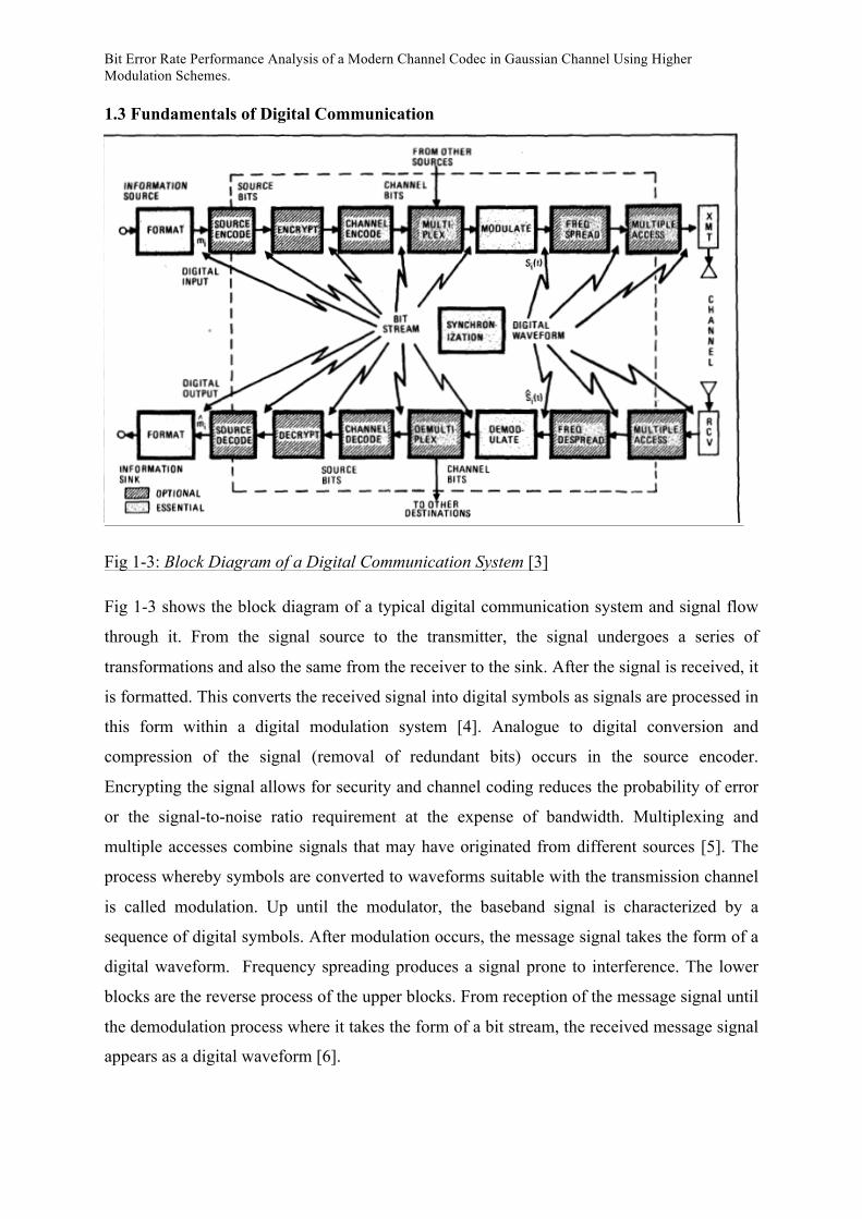
Fig 1-3: Block Diagram of a Digital Communication System [3]
Fig 1-3 shows the block diagram of a typical digital communication system and signal flow
through it. From the signal source to the transmitter, the signal undergoes a series of
transformations and also the same from the receiver to the sink. After the signal is received, it
is formatted. This converts the received signal into digital symbols as signals are processed in
this form within a digital modulation system [4]. Analogue to digital conversion and
compression of the signal (removal of redundant bits) occurs in the source encoder.
Encrypting the signal allows for security and channel coding reduces the probability of error
or the signal-to-noise ratio requirement at the expense of bandwidth. Multiplexing and
multiple accesses combine signals that may have originated from different sources [5]. The
process whereby symbols are converted to waveforms suitable with the transmission channel
is called modulation. Up until the modulator, the baseband signal is characterized by a
sequence of digital symbols. After modulation occurs, the message signal takes the form of a
digital waveform. Frequency spreading produces a signal prone to interference. The lower
blocks are the reverse process of the upper blocks. From reception of the message signal until
the demodulation process where it takes the form of a bit stream, the received message signal
appears as a digital waveform [6].

Bit Error Rate Performance Analysis of a Modern Channel Codec in Gaussian Channel Using Higher Modulation Schemes.
Despite the various digital communication system processes, there are three basic elements to
every digital communication system are the formatting, modulation and demodulation. The
process can be grouped into transmitter, the channel and the receiver. The transmitter
converts the message signal received into a suitable digital waveform for transmission over
the channel. Due to channel imperfections, the transmitted message signal is distorted by
noise during transmission and the received message signal is a corrupted version of the
transmitted message signal. A measure used to evaluate how much a signal has been
corrupted by noise is the SNR [7]. It compares the level of a signal to the level of background
noise and is defined the ratio of the average signal power to the average noise power. The
higher the ratio, the less obvious the background noise is. SNR is expressed in decibels (dBs).
The number of bit errors is due to the distortion of the transmitted signal as a result of noise
in the communication channel and can be defined as the number of received bits of data that
have been altered due to distortion in the channel. The number of bit errors divided by the
total number of transferred bits during a particular time interval is called the bit error rate
(BER) and is usually expressed as a percentage. The smaller the BER, the more reliable the
communication system is.
Two principal resources are exploited in a communication system and they are the
transmitted power and the channel bandwidth, hence communication channels can be
classified as either band limited or power limited. The transmitted power is the average
power of the transmitted signal while the channel bandwidth is defined as the band of
frequencies allocated for the transmission of the message signal [8].
Radio technology accelerated at a fast rate through the years to enable transmissions over
larger distances with better quality, less power and smaller devices thereby enabling public
radio communications and wireless networking. Radio waves are generally utilized by
antennas of appropriate size with wavelengths ranging from hundreds of meters to about one
millimetre. They are used for transmission of information through modulation. Television,
mobile phones and wireless networking all use radio waves.
1.4 Project Objectives
This project looks into some blocks in the digital communication system. These are the
formatting block, the channel encode, modulate, demodulate, and the channel decode blocks.

Bit Error Rate Performance Analysis of a Modern Channel Codec in Gaussian Channel Using Higher Modulation Schemes.
The overall aim of this project is to analyse a modern channel codec using the convolutional
coding technique and higher modulation schemes over a gaussian channel (AWGN Channel).
The project objectives are to understand
(a) Noise and its effect during data transmission.
(b) Maximum likelihood decoding using soft decision (SD).
(c) The correction of errors caused by noise by adding controlled amount of redundancy
using a convolutional codec.
(d) Viterbi convolutional decoding algorithm.
The project is divided into four parts
(a) Generation of additive white Gaussian noise (AWGN) and evaluation of its effects on a
data communication system
(b) Study of the performances of the different modulation schemes in the presence of AWGN
without error correction codes
(c) Comparison of the performances of the different modulation schemes in the presence of
AWGN
(d) Understand the effects of a (2, 1, 4) convolutional codec on the performance of a
communication system in the presence of AWGN.
(e) Comparison of the performance of the uncoded scheme and the coded scheme in terms of
coding gain.
The four modulation schemes to be implemented are BPSK, QPSK, 16QAM, and 64QAM.
The performances of the four schemes are compared in terms of plots of the bit error rate
(BER) against signal-to-noise ratio (SNR).
This projects aims to help understand the need to reduce errors caused by imperfection of the
channels through the use of error correction coding. For the completion of this project,
simulations are to be created using matlab to generate a random sequence data generator, the
different modulation schemes to be used, a Gaussian noise generator, a soft decision
demodulator, and a (2, 1, 4) convolutional encoder and its corresponding soft-output viterbi
decoder (SOVA).

Bit Error Rate Performance Analysis of a Modern Channel Codec in Gaussian Channel Using Higher Modulation Schemes.
1.5 Report Structure
The report is intended to provide a progressive description of the project background,
including the work done, accompanied by the results concluded in the end.
Chapter 2 covers the process design. It also emphasizes the most important blocks for DCS.
Chapter 3 discusses the channel model. It introduces AWGN noise and the channel capacity.
Chapter 4 considers the various modulation techniques and demodulation and deals with the
BER and SNR.
Chapter 5 introduces channel encoding and emphasizes on convolutional coding. Also it
analyses the performance of a DCS by comparing the graphs gotten for the BER for the
various modulation techniques used.
Chapter 6 is the conclusion.
2. PROCESS DESIGN
2.1 Block Diagram
Figure 2-1 shows the process design considered in this work. At the transmitter, input binary
data are randomly generated and convolutionally encoded before being passed into the
modulator. In the modulator, the encoded binary data (codeword sequence) are transformed
into signal waveforms by modulation (BPSK, QPSK, 16QAM and 64QAM). The signal
waveforms are passed through the channel model (AWGN) where it is corrupted by
randomly generated gaussian noise.

Bit Error Rate Performance Analysis of a Modern Channel Codec in Gaussian Channel Using Higher Modulation Schemes.
Figure 2-1: Block diagram for a communication link
At the receiver end, the reverse of what occured in the transmitting end ensues. The signal is
received at the receiving end corrupted with noise and demodulation takes place. The
demodulator converts a set of time ordered random variables into a code sequence and passes
it to the convolutional decoder. The decoder is then tasked with producing an estimate of the
original randomly generated input binary data.
3. CHANNEL MODEL
3.1 Additive White Gaussian Noise
Noise in the communication channel arises from different sources such as shot noise, black
body radiation from the earth and warm objects and thermal or Johnson noise. Thermal noise
is present in all communication systems and is caused by the thermal motion of electrons in
all dissipative components e.g. resistors and wires. It is a natural source of noise in the
channel that cannot be eliminated. Thermal noise described as a zero-mean Gaussian random
process has three important characteristics which are
Convolutional
Encoder Modulator
Convolutional
Decoder De-Modulator
AWGN
Channel
Input bits
Output bits
Bit Error Rate Performance Analysis of a Modern Channel Codec in Gaussian Channel Using Higher Modulation Schemes.
o Additive: This term implies that the noise is added or superimposed on the signal and
there is no multiplicative mechanism [9, 12].
o White: When the noise power has a uniform spectral density, it is referred to as white
noise. Here the power spectral density is flat for all frequencies because a thermal
noise source initiates an equal amount of noise power per unit bandwidth at all
frequencies [10].
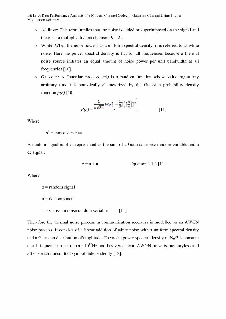
o Gaussian: A Gaussian process, n(t) is a random function whose value (n) at any
arbitrary time t is statistically characterized by the Gaussian probability density
function p(n) [10].
P(n) = [11]
Where
σ2 = noise variance
A random signal is often represented as the sum of a Gaussian noise random variable and a
dc signal.
z = a + n Equation 3.1.2 [11]
Where
z = random signal
a = dc component
n = Gaussian noise random variable [11]
Therefore the thermal noise process in communication receivers is modelled as an AWGN
noise process. It consists of a linear addition of white noise with a uniform spectral density
and a Gaussian distribution of amplitude. The noise power spectral density of N0/2 is constant
at all frequencies up to about 1012Hz and has zero mean. AWGN noise is memoryless and
affects each transmitted symbol independently [12].
Bit Error Rate Performance Analysis of a Modern Channel Codec in Gaussian Channel Using Higher Modulation Schemes.
3.2 Channel Capacity
The increasing demand for wireless communications makes it important to determine the
capacity limits of communication channels. The channel capacity of a communication
channel controls the maximum data rate that can be transmitted in a given time with
negligible amount of bit error.
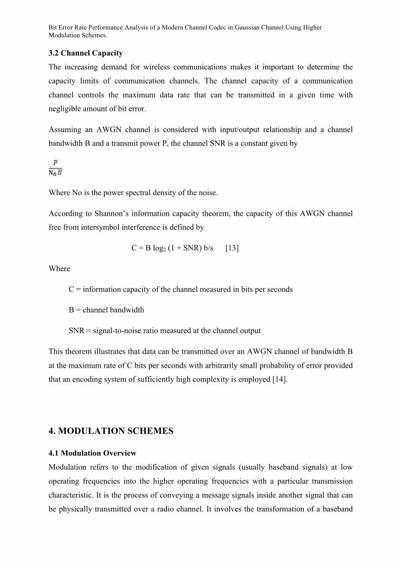
Assuming an AWGN channel is considered with input/output relationship and a channel
bandwidth B and a transmit power P, the channel SNR is a constant given by
Where No is the power spectral density of the noise.
According to Shannon’s information capacity theorem, the capacity of this AWGN channel
free from intersymbol interference is defined by
C = B log2 (1 + SNR) b/s [13]
Where
C = information capacity of the channel measured in bits per seconds
B = channel bandwidth
SNR = signal-to-noise ratio measured at the channel output
This theorem illustrates that data can be transmitted over an AWGN channel of bandwidth B
at the maximum rate of C bits per seconds with arbitrarily small probability of error provided
that an encoding system of sufficiently high complexity is employed [14].
4. MODULATION SCHEMES
4.1 Modulation Overview
Modulation refers to the modification of given signals (usually baseband signals) at low
operating frequencies into the higher operating frequencies with a particular transmission
characteristic. It is the process of conveying a message signals inside another signal that can
be physically transmitted over a radio channel. It involves the transformation of a baseband

Bit Error Rate Performance Analysis of a Modern Channel Codec in Gaussian Channel Using Higher Modulation Schemes.
message signal into a passband signal and is performed by altering some parameters of a
signal already at the required carrier frequency in accordance with the information to be
relayed. These parameters include the amplitude, phase and the frequency. The signal being
modified is referred to as the carrier signal and the signal doing the modification is called the
information signal. Varying the phase and the amplitude of the signal forms the basis of all
modulation schemes [15].
Modulation processes can be categorized into two methods.
o Continuous-Wave Modulation (CW): In this modulation process, a sinusoidal wave is
used as the carrier. For example, when the amplitude of the carrier is varied in
accordance with the message signal, it is referred to as amplitude modulation [16].
Other forms of this type of modulation include frequency modulation, angle
modulation and phase modulation. Passband data transmission modulates high
frequency sinusoidal carriers and can be called digital CW modulation.
o Pulse Modulation: Here, the carrier consists of a periodic sequence of rectangular
pulses [17].
In recent times, digital modulation techniques have taken over from analogue modulation
techniques. Examples of these modulation techniques include
o PSK: digital data modulates the phase of the carrier
o ASK: digital data modulates the amplitude of the carrier
o FSK: digital data modulates the frequency of the carrier
A unique pattern of binary bits are usually assigned equally to each of the phases, frequencies
and amplitudes in the above modulation techniques. The symbol represented by a particular
phase, frequency or amplitude comprises of this number of bits. In any M-ary system, the
alphabet M represents the total number of symbols and M = 2N. Each symbol represents a
message consisting of N bits [18]. The modulation alphabet M can be represented on a
constellation diagram for modulation schemes where the frequency of the modulated signal is
constant. The constellation diagram is a representation of a signal modulated by digital
modulation scheme. The symbols are represented as complex numbers and are viewed as
points on the complex plane. The in-phase signal and quadrature phase signals are substituted
for the real part (cosine carrier signal) and the imaginary part (sine carrier signal)
Bit Error Rate Performance Analysis of a Modern Channel Codec in Gaussian Channel Using Higher Modulation Schemes.
respectively. They are commonly called the I-axis and the Q-axis. The effect of noise affects
these components independently.
4.2 Detection and Demodulation
At the receiver, the transmitted signal across the AWGN channel becomes distorted as a
result of noise added to the signal. The received signal becomes disrupted by noise and is
expressed as
[19]
Where
r(t) = received signal
si(t) = transmitted signal
n(t) = zero mean Gaussian noise process
The receiver tries to undo the deterioration introduced by the channel and to demodulate the
received signal. It does this in two processes. First it detects the received signal by reducing it
to a single number with a signal component and noise component and finds the
mean value.
[20]
In the second step, a decision is made as to which signal was transmitted by comparing
to a threshold. The demodulator proceeds to convert the set of random variables into an
identical message sequence, similar to the originally input message sequence. However, the
demodulator can be configured in two ways.
o To give a hard output: In this form, the output of the demodulator is quantized on two
levels to give either a zero or a one.
o To give a soft output: In this form, the demodulator is implemented to give output
values greater than two quantization levels. It provides more information as compared
to hard output which is used to recover the message sequence with a better error
performance than that of hard output. Eventually, every message decision out of the
demodulator must be a hard one. [21]

Bit Error Rate Performance Analysis of a Modern Channel Codec in Gaussian Channel Using Higher Modulation Schemes.
4.3 PSK Modulation Scheme
This is a digital modulation scheme that transmits data by modulating the phase of a carrier
wave. Digital data is represented by a finite number of phases with each phase assigned a
unique pattern of binary bits. This unique pattern of bits each forms the symbol that is
represented by the particular phase. PSK modulation schemes can be represented on a
constellation diagram where the amplitude of each point along the in-phase axis is used to
modulate a cosine wave and the amplitude along the quadrature axis to modulate a sine wave.
The constellation points are chosen such that they are positioned with uniform angular
spacing round a circle so all the points can be transmitted with the same energy. BPSK and
QPSK modulations schemes are two examples of Modulation schemes that alter their phases.
The next two sub-chapters will consider BPSK and QPSK modulation schemes.
4.3.1 BPSK Modulation Scheme
Binary Phase Shift Key, the simplest form of PSK is a modulation scheme that uses two
phases separated by 180o or π radians, to relay information across the channel by adjusting
the phases of the carrier signal as needed. It is also be referred to as 2PSK or phase reversal
key (PRK) because of its antipodal state (i.e. states separated by ф = 180o). The carrier signal
is adjusted between these two phases. It has been stated that in any M-ary system, the
alphabet M represents the total number of symbols and the total number of bits per symbol
can be found from the mathematical expression M = 2N, where N is the number of bits. For
the BPSK modulation system, M = 2, thus N =1. This implies that the constellation diagram
for BPSK consists of two symbols and can only modulate at one bit per symbol. The
constellation diagram is shown in Fig 4-1.

Bit Error Rate Performance Analysis of a Modern Channel Codec in Gaussian Channel Using Higher Modulation Schemes.
Fig 4-1: Constellation Diagram for BPSK Modulation Scheme [22]
The general form for BPSK is expressed as
[23]
Where fc = frequency of the carrier wave.
Using the general form above, binary data can be transmitted with outputs of two phases (0
and π radians). For example to transmit a bit 1, the signal s1(t) is sent and is declared as
[24]
When the symbol is changed, the phase of the carrier is changed by π radians. Hence to
transmit a bit 0, the signal s0(t) is relayed where
= [25]
From the equations above, it is observed that a bit 1 is modulated into a +1 and a bit 0 is
modulated into a -1.
The theoretical BER of BPSK in AWGN is expressed below
[26]
The Matlab scripts used in this project generated random bits of 0’s and 1’s before
modulating them digitally (BPSK modulation) into -1’s and +1’s, respectively. At the
receiver end, the received soft values (also known as the channel observation), was directly
fed into the detection scheme, where soft values below 0 were detected as bit 0 while soft
values above 0 detected as bit 1. (If there we to be a SOVA decoder involved, then the
received soft values are fed directly into the SOVA, and the output of the SOVA is then
detected digitally as explained above).

Bit Error Rate Performance Analysis of a Modern Channel Codec in Gaussian Channel Using Higher Modulation Schemes.
The plot of the BER against the SNR is obtained to analyse the performance of BPSK
modulation in a digital communication system. Fig 4-2 shows the curve obtained.
Fig 4-2: Theoretical and Simulated BER against SNR in AWGN for BPSK
BPSK modulation is one of the most potent of all the Phase Shift Key forms because it takes
an extremely high level of noise for the demodulator to make an incorrect decision. Also its
ease of demodulation, power efficiency, low cost of implementation and straight forward
carrier recovery are further reasons for its potency. For these reasons, applications such as
power line communications, cable modems, deep space telemetry and GPS still use BPSK
modulation schemes. [27]
4.3.2 QPSK Modulation Schemes
QPSK modulation scheme is also known as 4-PSK consists of BPSK modulation on both the
in-phase and quadrature components of the signal. In a QPSK modulation scheme, two
successive bits in a data sequence are grouped together. Consequently, the data rate is

Bit Error Rate Performance Analysis of a Modern Channel Codec in Gaussian Channel Using Higher Modulation Schemes.
doubled as compared to that of the BPSK modulation scheme or the bit rate is reduced. This
reduction is bit rate, causes a direct reduction in the bandwidth of the channel. The reason for
this reduction is that in a communication system, the channel bandwidth depends on the bit
rate and when two or more bits are combined on a symbol, the bit rate is reduced. This
reduction in the bit rate also causes a reduction in the frequency of the carrier required. Thus,
as a result of the grouping of bits in symbols, the transmission channel bandwidth is reduced.
Also, the BER for QPSK modulation scheme is exactly the same as the BER for BPSK
because QPSK maintains the same data-rate of BPSK but at half the bandwidth of BPSK.
QPSK uses four points (symbols) on the constellation diagram spaced equally around a circle.
It undergoes four changes in phase and as a result can encode two bits per symbol because 4
= 22. When the symbol is changed to the next symbol, the phase of the carrier is changed by
π/4 radians (45 degrees). A symbol error will occur if the received signal is displaced across
either of the axis. The probability of displacement is the same in each direction.
Fig 4-3: Constellation Diagram for QPSK Modulation Scheme
The general form for QPSK is shown below
[28]
Bit Error Rate Performance Analysis of a Modern Channel Codec in Gaussian Channel Using Higher Modulation Schemes.
This yields four phases’ π/4, 3π/4, 5π/4, and 7π/4.
In this project, the randomly generated bits were paired into two’s with each pair digitally
modulated. At the receiver end, the received soft values pertaining to the transmitted bits are
then demodulated using soft demodulation. In the soft demodulator, the received soft bits are
firstly detected and converted into 1’s and 0’s (corresponding to the received bit as at the
transmitter). For example if soft bits [-0.45 2.32] is received, this is converted into a [0 1]
bits. Euclidean distance between the received soft value and their corresponding received bits
of 0’s and 1 is then evaluated for symbols whose input bits are 0’s or a 1 for the entire QPSK
constellation scheme. The minimum Euclidean distance for each comparison is then selected
and subtracted from each other, resulting to the soft output from the demodulator.
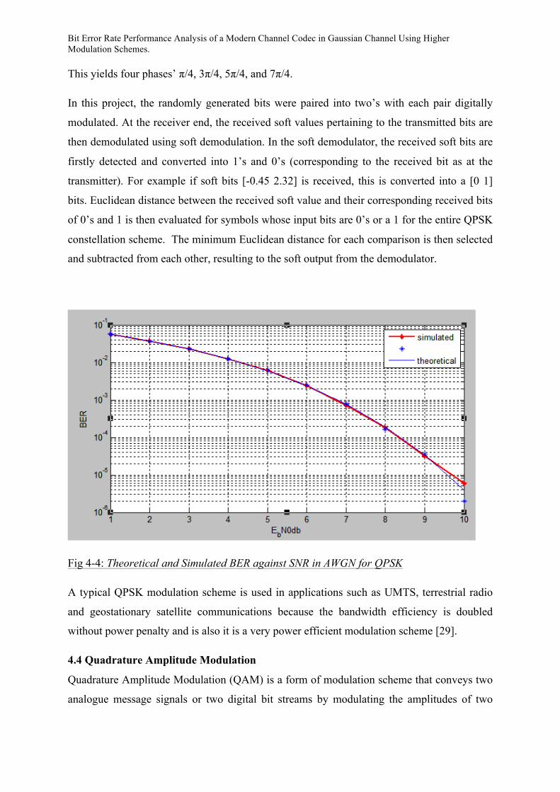
Fig 4-4: Theoretical and Simulated BER against SNR in AWGN for QPSK
A typical QPSK modulation scheme is used in applications such as UMTS, terrestrial radio
and geostationary satellite communications because the bandwidth efficiency is doubled
without power penalty and is also it is a very power efficient modulation scheme [29].
4.4 Quadrature Amplitude Modulation
Quadrature Amplitude Modulation (QAM) is a form of modulation scheme that conveys two
analogue message signals or two digital bit streams by modulating the amplitudes of two

Bit Error Rate Performance Analysis of a Modern Channel Codec in Gaussian Channel Using Higher Modulation Schemes.
carrier waves using the amplitude shift keying digital modulation scheme. Two physically
dependent message signals are applied to two separate product modulators that are supplied
with two carrier waves of the same frequency but differing in phase by 90o [30]. They are
called quadrature carriers or components as a result of this difference. The transmitted signal
consists of a sum of these two products modulator outputs and they occupy the same
bandwidth. The resulting signal after the combination is a combination of both phase-shift
keying and amplitude-shift keying. At the receiver output, separation of the two message
signals occurs; hence it can be viewed as a bandwidth conservation scheme [31].
QAM conveys data by changing some aspect of a carrier signal in response to a data signal.
The amplitude of two waves, 90 degrees out-of-phase with each other (in quadrature) are
changed (modulated or keyed) to represent the data signal. Amplitude modulating two
carriers in quadrature can be equivalently viewed as both amplitude modulating and phase
modulating a single carrier.
In QAM, constellation points are arranged with vertical and horizontal spacing in a squared
grid. 16 QAM, 64 QAM, 128 QAM and 256 QAM are some of the most common forms of
QAM. With the increasing number of constellation points, the points get closer together and
it is possible to transmit more bits per symbol. However, due to the close proximity of these
points to each other, they are more susceptible to noise thus resulting in a higher BER.
Hence, a higher order QAM has a higher data rate but relays data less accurately that lower
order QAM.
The QAM signal waveform is expressed as
[32]
Where Am =
AI and AQ are information bearing signal amplitudes of the quadrature carriers and is the
phase modulation. The next section of this report focuses on the 16 QAM and the 64 QAM.

Bit Error Rate Performance Analysis of a Modern Channel Codec in Gaussian Channel Using Higher Modulation Schemes.
4.4.1 16 QAM
In 16QAM modulation, 16 points are present on the constellation diagram. It includes four in-
phase values and four quadrature values resulting in 16 different states for the signal. 4 bits
per symbol can be transmitted consisting of two bits for the in-phase component and two bits
for the quadrature component. Different ways exists of building up the signal constellation,
however rectangular signal constellations have the noticeable advantage that they can be
generated as two PAM signal impressed on the phase quadrature carriers and can easily be
demodulated. The constellation diagram is shown in Fig 4-5 below
Fig 4-5: Constellation Diagram for 16 QAM Modulation Scheme [33]
As was mentioned earlier, in 16 QAM, the four bits transmitted can be split into I and Q
components. Assuming the first and second bits b0and b1 respectively represents the I
component, and the third and fourth bits b2 and b3 represents the Q components, a table of
the I and Q components can be drawn [ Table 4-1]. If for instance an input sequence of 0000,
1101 is to be modulated, the two bits for the Q component are 00 and 11 while the two bits
for the I component are 00 and 01. From the table, it is observed that when modulated, 00 and
11 on the Q component modulate to -3 and +1 respectively while 00 and 01 on the I
component modulates to -3 and -1. Thus when combined, 0000 and 1101 is modulated to
(-3, -3) and (+1, -1).

Bit Error Rate Performance Analysis of a Modern Channel Codec in Gaussian Channel Using Higher Modulation Schemes.
b0b1 I b2b3 Q
00 -3 00 -3
01 -1 01 -1
11 +1 11 +1
10 +3 10 +3
Table 4-1: Constellation Mapping for 16 QAM
Performance of 16 QAM in AWGN in the case of BER can be expressed as
[34]
In this project, the randomly generated bits were paired into four’s with each pair digitally
modulated. At the receiver end, the received soft values pertaining to the transmitted bits are
then demodulated using soft demodulation. In the soft demodulator, the received soft bits are
firstly detected and converted into 1’s and 0’s (corresponding to the received bit as at the
transmitter). For example if soft bits [-0.45 2.32 1.45 -0.33] is received, this is converted into
a [0 1 1 0] bits. Euclidean distance between the received soft value and their corresponding
received bits of 0’s and 1 is then evaluated for symbols whose input bits are 0’s or a 1 for the
entire 16QAM constellation scheme. The minimum Euclidean distance for each comparison
is then selected and subtracted from each other, resulting to the soft output from the
demodulator.

Bit Error Rate Performance Analysis of a Modern Channel Codec in Gaussian Channel Using Higher Modulation Schemes.
Fig 4-6: Theoretical and Simulated BER against SNR for 16 QAM in AWGN
4.4.2 64 QAM
In 64QAM modulation, 64 points are present on the constellation diagram. It includes eight
in-phase values and eight quadrature values resulting in 64 different states for the signal. 6
bits per symbol can be transmitted consisting of three bits for the in-phase component and
three bits for the quadrature component. The constellation diagram is shown in Fig 4-7.
Bit Error Rate Performance Analysis of a Modern Channel Codec in Gaussian Channel Using Higher Modulation Schemes.
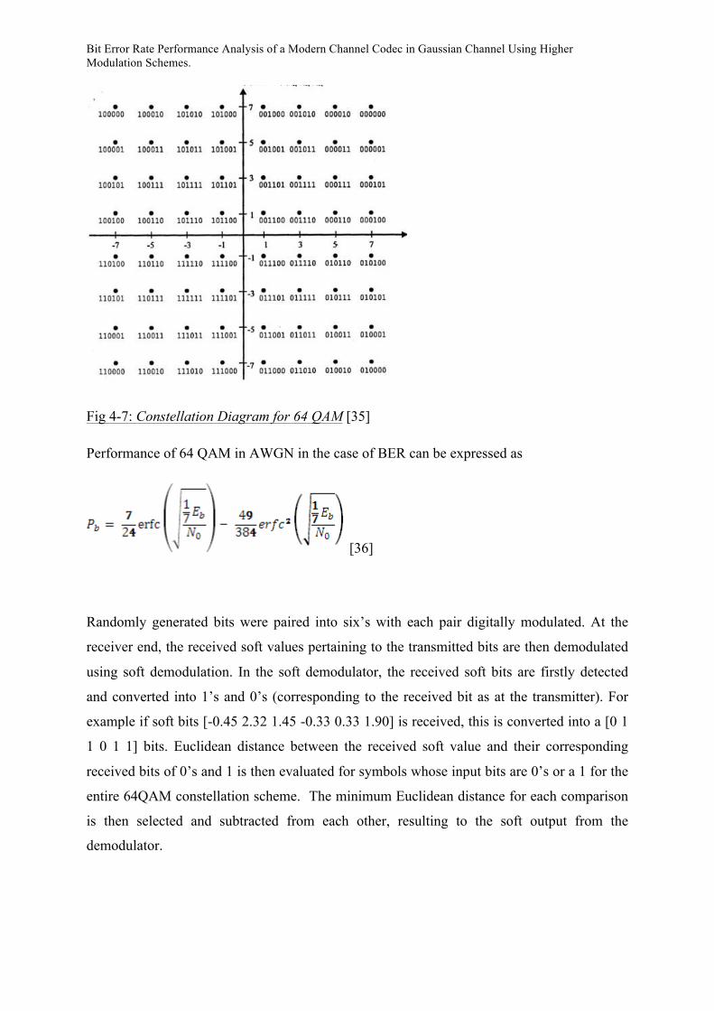
Fig 4-7: Constellation Diagram for 64 QAM [35]
Performance of 64 QAM in AWGN in the case of BER can be expressed as
[36]
Randomly generated bits were paired into six’s with each pair digitally modulated. At the
receiver end, the received soft values pertaining to the transmitted bits are then demodulated
using soft demodulation. In the soft demodulator, the received soft bits are firstly detected
and converted into 1’s and 0’s (corresponding to the received bit as at the transmitter). For
example if soft bits [-0.45 2.32 1.45 -0.33 0.33 1.90] is received, this is converted into a [0 1
1 0 1 1] bits. Euclidean distance between the received soft value and their corresponding
received bits of 0’s and 1 is then evaluated for symbols whose input bits are 0’s or a 1 for the
entire 64QAM constellation scheme. The minimum Euclidean distance for each comparison
is then selected and subtracted from each other, resulting to the soft output from the
demodulator.

Bit Error Rate Performance Analysis of a Modern Channel Codec in Gaussian Channel Using Higher Modulation Schemes.
Fig 4-8: Theoretical and Simulated BER against SNR for 64 QAM
4.5 Comparisons of BER in AWGN for Different Modulation Schemes
From the graphs of the BER against SNR obtained, comparisons can be made for the
different modulation schemes. It is observed that for the same data rate for BPSK and QPSK
modulation schemes, the BER are exactly the same but QPSK modulates at half the
bandwidth of BPSK. Also, it is noticed that as the number of constellation point increases, the
data rate increases but modulation schemes with a high number of constellation points are
more prone to error than those with lower constellation points. This increase in the BER,
results from the compact nature of the points on the constellation diagram for high
modulation schemes.

Bit Error Rate Performance Analysis of a Modern Channel Codec in Gaussian Channel Using Higher Modulation Schemes.
5. CHANNEL ENCODING
5.1 Overview of Channel Coding
The channel encoder aims to protect the source data against errors introduced by noise and
other types of distortion [37]. Channel encoding can be segmented into two study areas which
are waveform coding and structured sequences. Waveform coding deals with the
transformation of the waveform into better waveforms to enable detection process less
susceptible to errors. Structured sequences have to do with transformation of data sequences
into better sequences having structured redundancy (redundant bits). The redundant bits are
utilized at the receiver used for the detection and correction of errors [38, 37].
Two types of channel coding are
1 Block Coding: In this form of coding, the encoder accepts information in successive k-bit
blocks. The successive k-bit blocks are independent hence the encoder has zero-memory. The
encoder adds (n-k) redundant bits derived from logical operations on the k information bits to
form n-bit codewords [39].
2. Convolutional Coding: The encoder accepts information bits as a continuous sequence and
needs a memory of length m because the successive m bits are dependent. The encoder
operates on the incoming sequence using a sliding window of length m bits.
This report focuses on the convolutional coding type of channel coding.
5.2 Convolutional Coding
Convolution coding described by 3 integers n, k and K, is a form of error-correcting code
where the code rate of the code is k/n (information per coded bit). Redundant bits are
generated using modulo-2 convolutions. k is the information bit symbol to be encoded, and
this is transformed into an n-bit symbol. K the constraint length of the convolutional code,
expressed in bits is defined as the number of shifts over which a single message bit can
influence the encoder output [40]
An important characteristic of convolutional codes that differentiates it from block codes is
the availability of a memory in the encoder. Another characteristic of convolutional coding is
that the encoder must deal with sequences as the codeword cannot be separated unlike in
block coding where codewords are produced on a block by block basis. In an encoder with an
Bit Error Rate Performance Analysis of a Modern Channel Codec in Gaussian Channel Using Higher Modulation Schemes.
m-stage shift register, the memory of the encoder equals m message bits and K=M+1 shift are
required for a message bit to enter the shift register and finally come out. The memory order
of the code M=K-1.
How does it work? Each message sequence m is transformed into a unique codeword
U = G(m), where G is the generator polynomial. At each unit of time, k-bits are shifted into
the first k stages of the register. The bits in the memory register are shifted k stages to the
right and the outputs of the n adders are sequentially sampled to obtain the binary code
symbols or coded bits. In convolutional coding, a given k-tuple within m does not uniquely
define its assiociated n-tuple within U since the encoding of each k-tuple is not only a
function of that k-tuple but is also a function of the K-1 input k-tuples that preceeds it [41]
The modulator uses these code symbols to decide the waveforms to be transmitted over the
channel. Shifts register implements sliding windows and the input data are presented a block
at a time to k shift registers in parallel through a demultiplexer [42]. Output of the shift
registers are combined by n sets of weighted modulo-n adders.
A convolutional encoder can be represented in a couple of ways.
• Connection representation [43]
• Polynomial representation
• State Diagram
• Tree Diagram
• Trellis Diagram
The connection representation is the easiest to understand but the most important are the State
diagram, tree diagram and the trellis diagram.
For the implementation of the tree diagram, each branch of the tree represents an input
symbol with the corresponding pair of output binary symbols indicated on the branch. An
input 0, specifies the upper part of the branch, and a 1 represents the lower branch. A specific
path in the tree is traced from the left to the right in accordance with the input message
sequence to get its coded form. The corresponding coded symbols on the branches of that
path constitute the input message sequence. However, a primary setback in the tree diagram
is the size of the tree. The number of branches on the tree increases as a function of 2L where

Bit Error Rate Performance Analysis of a Modern Channel Codec in Gaussian Channel Using Higher Modulation Schemes.
L represents the number of bits in the message input sequence. The causes an exponential
increase in the size of the tree with the length of the message sequence and quickly becomes
unrestrained. This increase in size leads to a large amount of redundancy in the diagram and
it is observed that after a time t = K, the tree structure repeats itself. The reason being for this
that generally in the implementation of tree diagrams, the tree structure repeats itself after K
branching and from there onwards, the upper and lower halves of the trees are identical [44].
Since the upper and lower halves of the tree are identical and all succeeding paths will be
indistinguishable, they can be merged to reduce its size. The merging of these halves of the
tree diagram results in the trellis diagram.
The trellis diagram provides a more controllable encoder than the tree diagram and is very
important in convolutional coding as it is used for the decoding process. The concept for the
implementation of the trellis diagram is almost the same as that for the tree diagram but in
this, the output generated by an input bit 0 is represented by a straight solid line and the
output generated by an input bit 1 is represented by dashed lines. At each unit of time the
trellis requires 2K-1 nodes to represent the 2K-1 possible encoder states [45].
A convolutional encoder may take up a finite number of states between which it moves at
each block period according to the input block. The state diagram is a directed graph showing
the states and the allowed transitions between them. Branch labels indicate data input and
code output for each state transition in the form data/code.
A convolutional encoder may be systematic or non-systematic. A systematic convolutional
encoder is one in which the information bits and the parity bits are separated while in a non-
systematic convolutional code, the information bit and the parity bits cannot be separated.
Also, a convolutional code can be recursive or non-recursive. A non-recursive convolutional
code is one that has only a feed forward system but no feedback. A recursive convolutional
code employs a feedback mechanism (feeding one or more of the tap outputs in the shift
register back to the input) [46].

Bit Error Rate Performance Analysis of a Modern Channel Codec in Gaussian Channel Using Higher Modulation Schemes.
5.3 Viterbi Decoding Algorithm
The concept for decoding a convolutional code is the Maximum Likelihood Decoding (MLD)
concept. According to this concept, the decoder chooses a particular received codeword
sequence corrupted with noise as the transmitted sequence if the likelihood is greater than all
the other possible likelihoods of the other transmitted sequences. The viterbi decoding
algorithm is the decoder used in decoding convolutional codes and it performs MLD.
Viterbi decoding algorithm was discovered by viterbi in 1967 [47]. It uses the trellis diagram
for the decoding process. This algorithm involves calculating a measure of similarity or
distance between the received signal at a particular time instant and all the trellis paths
entering each state at that time instant. The decoder does this and advances deeper into the
trellis eliminating trellis paths not considered for maximum likelihood choice from the trellis
diagram. When two paths enter the same state, the chosen path is called the surviving path
[48].
Two types of viterbi decoding include:
1. Hard output-decision Viterbi Algorithm (HODA): finds a path through the trellis that
most likely resembles the received code sequence and deletes the other paths. This
closest path here is found in terms of Hamming distance. Also, the output of the
demodulator here is quantized to two levels, 0 and 1 and fed into the decoder.
2. Soft output-decision Viterbi Algorithm (SOVA): Here, Euclidean distance metric is
used instead of hamming distance. The received bit used in the Euclidean distance
metric is processed by multi-bit quantization. This method provides the decoder with
more information than is provided in the hard decision case.
Every message decision out of the decoder must be a hard decision however; soft-decision
viterbi algorithm provides the decoder with more information which helps for better
recovering of the message sequence with a better error performance as compared to that of
hard decision decoding.
This report shall discuss a Recursive Systematic Convolutional code (RSC). This is a
convolutional code that has both feedfoward generator and feedback generator and where the
input and parity bits are easily separable. The reason for making the convolutional codes
recursive is to make the internal state of shift register depend on past outputs. This affects the
behaviour of the error patterns (a single error in the systematic bit produces an infinite

Bit Error Rate Performance Analysis of a Modern Channel Codec in Gaussian Channel Using Higher Modulation Schemes.
number of parity errors), with the results that a better performance of the overall coding
strategy is attained [49].
The feedfoward generator in octal is 15 but translates to 1101 in binary. The feedback
generator is 13 in octal and translates to 1011 in binary. The convolutional encode has an
input of one (i.e. it takes a message sequence one at a time) and an output of two. This gives
it a code rate of ½.
5.4 Modulation Schemes with Convolutional Code
QPSK with Convolutional Code
In this project, randomly generated information bits are firstly encoded with the
Convolutional encoder. The encoded bits are then digitally modulated using the BPSK
modulation scheme. The modulated signals are then transmitted in a Gaussian channel. At
the receiver end, the received soft values are then directly fed into the SOVA decoder. The
SOVA decoder then outputs soft values which it believes is the originally transmitted symbol.
The output from the SOVA is then sent into a detector to where soft values lower than zero is
assigned a 0 and soft values above zero is assigned a 1. The detected bits are then compared
with the originally generated random bits for the computation of the bit error rate (BER) at
that particular signal to noise ratio.
Fig 5-1: BPSK with Convolutional Code and theoretical and Simulated BER against SNR in
AWGN

Bit Error Rate Performance Analysis of a Modern Channel Codec in Gaussian Channel Using Higher Modulation Schemes.
QPSK with Convolutional Code
In this project, randomly generated information bits are firstly encoded with the
Convolutional encoder. The encoded bits are then digitally modulated using the QPSK
modulation scheme. The modulated signals are then transmitted in a complex Gaussian
channel. At the receiver end, the received soft values are then sent into the QPSK soft
demodulator as explained in the case of the uncoded QPSK system. The output from soft
demodulator is then fed into the SOVA decoder. The SOVA decoder then outputs soft values
which it believes is the originally transmitted symbol.
The output from the SOVA is then sent into a detector to where soft values lower than zero is
assigned a 0 and soft values above zero is assigned a 1. The detected bits are then compared
with the originally generated random bits for the computation of the bit error rate (BER) at
that particular signal to noise ratio.
Fig 5-2: QPSK with Convolutional Code and theoretical and Simulated BER against SNR in
AWGN
Bit Error Rate Performance Analysis of a Modern Channel Codec in Gaussian Channel Using Higher Modulation Schemes.
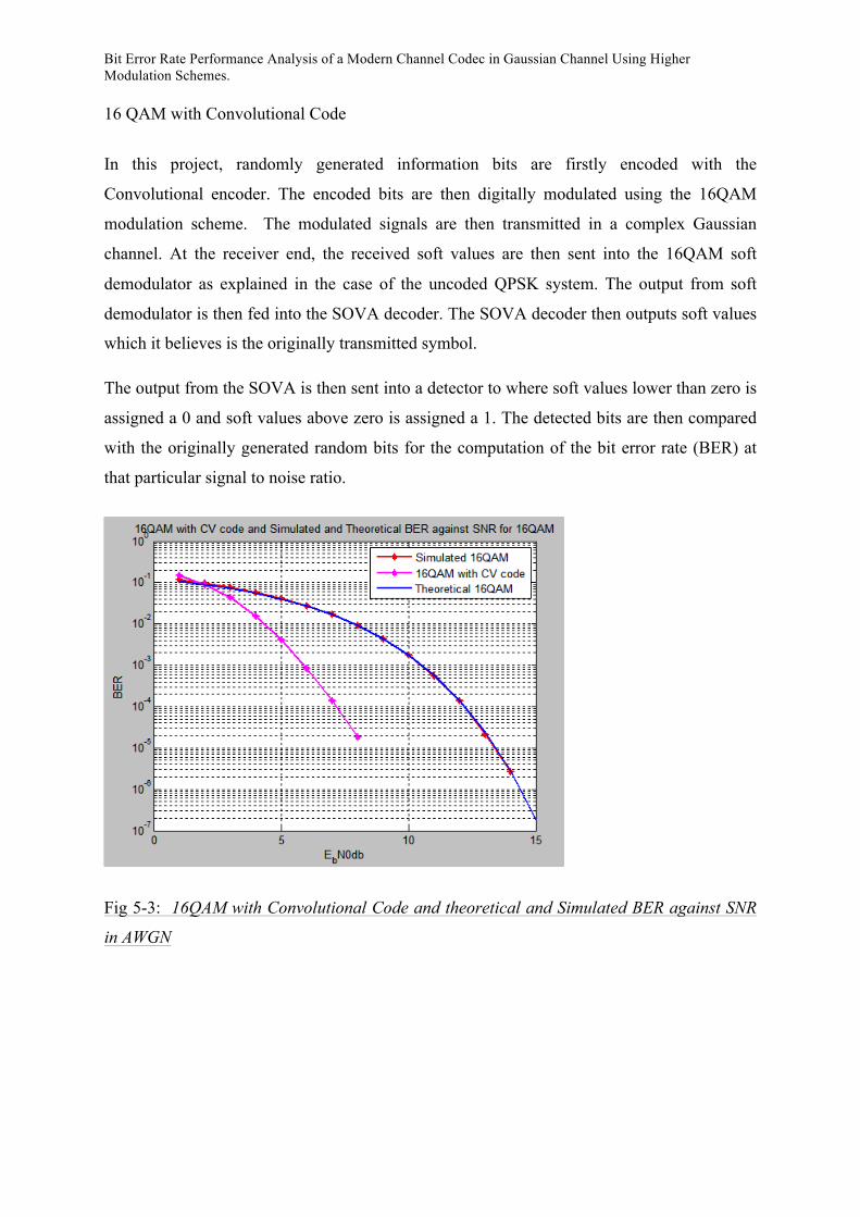
16 QAM with Convolutional Code
In this project, randomly generated information bits are firstly encoded with the
Convolutional encoder. The encoded bits are then digitally modulated using the 16QAM
modulation scheme. The modulated signals are then transmitted in a complex Gaussian
channel. At the receiver end, the received soft values are then sent into the 16QAM soft
demodulator as explained in the case of the uncoded QPSK system. The output from soft
demodulator is then fed into the SOVA decoder. The SOVA decoder then outputs soft values
which it believes is the originally transmitted symbol.
The output from the SOVA is then sent into a detector to where soft values lower than zero is
assigned a 0 and soft values above zero is assigned a 1. The detected bits are then compared
with the originally generated random bits for the computation of the bit error rate (BER) at
that particular signal to noise ratio.
Fig 5-3: 16QAM with Convolutional Code and theoretical and Simulated BER against SNR
in AWGN

Bit Error Rate Performance Analysis of a Modern Channel Codec in Gaussian Channel Using Higher Modulation Schemes.
64 QAM with Convolutional Code
In this project, randomly generated information bits are firstly encoded with the
Convolutional encoder. The encoded bits are then digitally modulated using the 16QAM
modulation scheme. The modulated signals are then transmitted in a complex Gaussian
channel. At the receiver end, the received soft values are then sent into the 16QAM soft
demodulator as explained in the case of the uncoded QPSK system. The output from soft
demodulator is then fed into the SOVA decoder. The SOVA decoder then outputs soft values
which it believes is the originally transmitted symbol.
The output from the SOVA is then sent into a detector to where soft values lower than zero is
assigned a 0 and soft values above zero is assigned a 1. The detected bits are then compared
with the originally generated random bits for the computation of the bit error rate (BER) at
that particular signal to noise ratio.
Fig 5-4: 64QAM with Convolutional Code and theoretical and Simulated BER against SNR
in AWGN
Bit Error Rate Performance Analysis of a Modern Channel Codec in Gaussian Channel Using Higher Modulation Schemes.
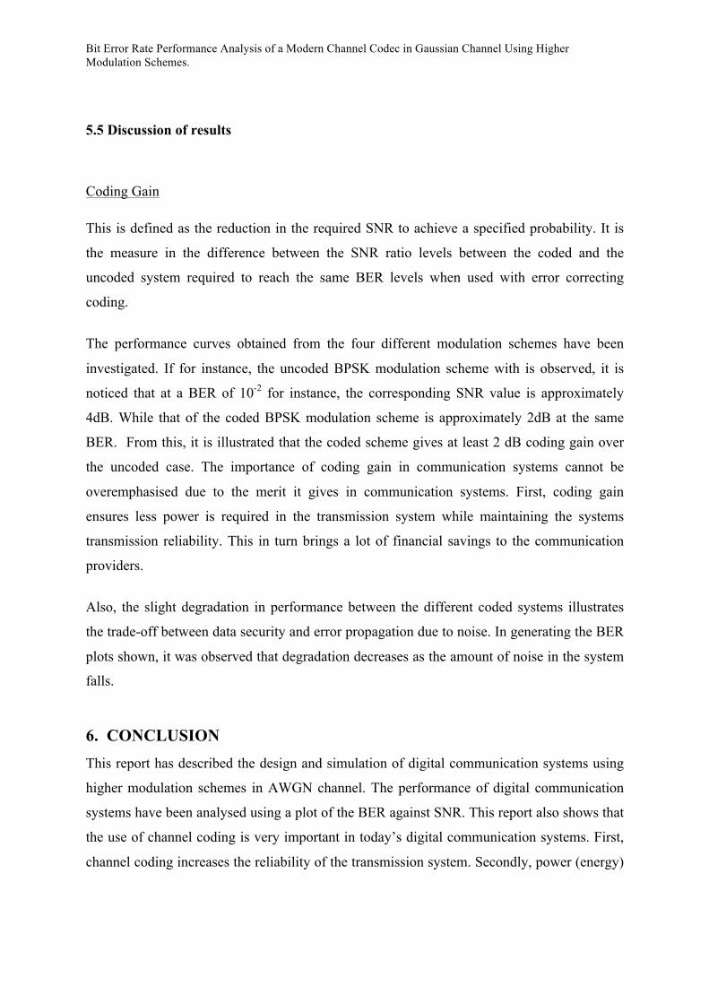
5.5 Discussion of results
Coding Gain
This is defined as the reduction in the required SNR to achieve a specified probability. It is
the measure in the difference between the SNR ratio levels between the coded and the
uncoded system required to reach the same BER levels when used with error correcting
coding.
The performance curves obtained from the four different modulation schemes have been
investigated. If for instance, the uncoded BPSK modulation scheme with is observed, it is
noticed that at a BER of 10-2 for instance, the corresponding SNR value is approximately
4dB. While that of the coded BPSK modulation scheme is approximately 2dB at the same
BER. From this, it is illustrated that the coded scheme gives at least 2 dB coding gain over
the uncoded case. The importance of coding gain in communication systems cannot be
overemphasised due to the merit it gives in communication systems. First, coding gain
ensures less power is required in the transmission system while maintaining the systems
transmission reliability. This in turn brings a lot of financial savings to the communication
providers.
Also, the slight degradation in performance between the different coded systems illustrates
the trade-off between data security and error propagation due to noise. In generating the BER
plots shown, it was observed that degradation decreases as the amount of noise in the system
falls.
6. CONCLUSION This report has described the design and simulation of digital communication systems using
higher modulation schemes in AWGN channel. The performance of digital communication
systems have been analysed using a plot of the BER against SNR. This report also shows that
the use of channel coding is very important in today’s digital communication systems. First,
channel coding increases the reliability of the transmission system. Secondly, power (energy)

Bit Error Rate Performance Analysis of a Modern Channel Codec in Gaussian Channel Using Higher Modulation Schemes.
savings is done with the use of channel coding to the advantage of the communication service
providers and also making the world a greener place to live.
Bit Error Rate Performance Analysis of a Modern Channel Codec in Gaussian Channel Using Higher Modulation Schemes.
References [1] Haykin S. 4ed. Communication Systems. New Jersey: John Wiley & Sons, 2001.
[2] Haykin S. 4ed. Communication Systems. New Jersey: John Wiley & Sons, 2001.
[3] Bernard S. A Structured Overview of Digital Communications. IEEE Communications
Magazine, August 1983, Fig 1, p.5.
[4] Bernard S. 2ed. Digital Communications: Fundamentals and Applications. New Jersey:
Prentice Hall, 2001.
[5] Bernard S. 2ed. Digital Communications: Fundamentals and Applications. New Jersey:
Prentice Hall, 2001.
[6] Bernard S. 2ed. Digital Communications: Fundamentals and Applications. New Jersey:
Prentice Hall, 2001.
[7] Haykin S. 4ed. Communication Systems. New Jersey: John Wiley & Sons, 2001.
[8] Haykin S. 4ed. Communication Systems. New Jersey: John Wiley & Sons, 2001.
[9] Bernard S. 2ed. Digital Communications: Fundamentals and Applications. New Jersey:
Prentice Hall, 2001.
[10] Bernard S. 2ed. Digital Communications: Fundamentals and Applications. New Jersey:
Prentice Hall, 2001.
[11] Bernard S. 2ed. Digital Communications: Fundamentals and Applications. New Jersey:
Prentice Hall, 2001.
[12] Li X Zhang. ELEC 5446, Coding and Modulation for Digital Communication System
Lecture Notes, University of Leeds UK, 2009, not published.
[13] Bernard S. 2ed. Digital Communications: Fundamentals and Applications. New Jersey:
Prentice Hall, 2001.
[14] Haykin S. 4ed. Communication Systems. New Jersey: John Wiley & Sons, 2001.
[15] Li X Zhang. ELEC 5446, Coding and Modulation for Digital Communication System
Lecture Notes, University of Leeds UK, 2009, not published.

Bit Error Rate Performance Analysis of a Modern Channel Codec in Gaussian Channel Using Higher Modulation Schemes.
[16] Haykin S. 4ed. Communication Systems. New Jersey: John Wiley & Sons, 2001.
[17] Haykin S. 4ed. Communication Systems. New Jersey: John Wiley & Sons, 2001.
[18] Proakis J. 4ed Digital Communications. New York, McGraw Hill, 2000
[19] Bernard S. 2ed. Digital Communications: Fundamentals and Applications. New Jersey:
Prentice Hall, 2001.
[20] Bernard S. 2ed. Digital Communications: Fundamentals and Applications. New Jersey:
Prentice Hall, 2001.
[21] Bernard S. 2ed. Digital Communications: Fundamentals and Applications. New Jersey:
Prentice Hall, 2001.
[22]
[23] Haykin S. 4ed. Communication Systems. New Jersey: John Wiley & Sons, 2001.
[24] Haykin S. 4ed. Communication Systems. New Jersey: John Wiley & Sons, 2001.
[25] Haykin S. 4ed. Communication Systems. New Jersey: John Wiley & Sons, 2001.
[26] Haykin S. 4ed. Communication Systems. New Jersey: John Wiley & Sons, 2001.
[27] Li X Zhang. ELEC 5446, Coding and Modulation for Digital Communication System
Lecture Notes, University of Leeds UK, 2009, not published.
[28] Haykin S. 4ed. Communication Systems. New Jersey: John Wiley & Sons, 2001.
[29] Li X Zhang. ELEC 5446, Coding and Modulation for Digital Communication System
Lecture Notes, University of Leeds UK, 2009, not published.
[30] Li X Zhang. ELEC 5446, Coding and Modulation for Digital Communication System
Lecture Notes, University of Leeds UK, 2009, not published.
[31] Li X Zhang. ELEC 5446, Coding and Modulation for Digital Communication System
Lecture Notes, University of Leeds UK, 2009, not published.
[32] Santoso T. B. Developing on Simulation Programming of 16QAM in the AWGN Channel
[online]. [Accessed 2nd May 2011]. Available from: http://lecturer.eepis-
its.edu/~tribudi/LN_suzuki_fukawa_lab/finalr7.pdf

Bit Error Rate Performance Analysis of a Modern Channel Codec in Gaussian Channel Using Higher Modulation Schemes.
[33] DSP Log Signal Processing for Communication [online]. [Accessed 3rd May 2011].
Available from: http://www.dsplog.com/2008/06/05/16qam-bit-error-gray-mapping/
[34] Harada H and Prasad R: Simulation and Software Radio for Mobile Communications.
Boston, Artech House Publishers.
[35] [online]. [Accessed 10th May 2011]. Available from
http://www.atmovermpeg.com/images/64-qam-constellation-diagram.gif
[36] Harada H and Prasad R: Simulation and Software Radio for Mobile Communications.
Boston, Artech House Publishers.
[37] Li X Zhang. ELEC 2430, Channel Coding. Lecture Notes, University of Leeds UK,
2010, not published.
[38] Bernard S. 2ed. Digital Communications: Fundamentals and Applications. New Jersey:
Prentice Hall, 2001.
[39] Li X Zhang. ELEC 2430, Channel Coding. Lecture Notes, University of Leeds UK,
2010, not published.
[40] Bernard S. 2ed. Digital Communications: Fundamentals and Applications. New Jersey:
Prentice Hall, 2001.
[41] Bernard S. 2ed. Digital Communications: Fundamentals and Applications. New Jersey:
Prentice Hall, 2001.
[42] Li X Zhang. ELEC 5446, Coding and Modulation for Digital Communication System
Lecture Notes, University of Leeds UK, 2009, not published.
[43] Bernard S. 2ed. Digital Communications: Fundamentals and Applications. New Jersey:
Prentice Hall, 2001.
[44] Bernard S. 2ed. Digital Communications: Fundamentals and Applications. New Jersey:
Prentice Hall, 2001.
[45] Bernard S. 2ed. Digital Communications: Fundamentals and Applications. New Jersey:
Prentice Hall, 2001.

Bit Error Rate Performance Analysis of a Modern Channel Codec in Gaussian Channel Using Higher Modulation Schemes.
[46] Bernard S. 2ed. Digital Communications: Fundamentals and Applications. New Jersey:
Prentice Hall, 2001.
[47] Bernard S. 2ed. Digital Communications: Fundamentals and Applications. New Jersey:
Prentice Hall, 2001.
[48] Bernard S. 2ed. Digital Communications: Fundamentals and Applications. New Jersey:
Prentice Hall, 2001.
[49] Bernard S. 2ed. Digital Communications: Fundamentals and Applications. New Jersey:
Prentice Hall, 2001.
Bibliography
Bit Error Rate Performance Analysis of a Modern Channel Codec in Gaussian Channel Using Higher Modulation Schemes.
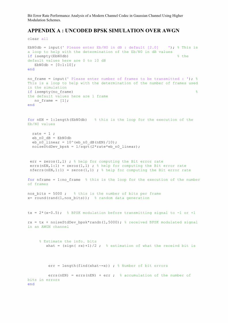
APPENDIX A : UNCODED BPSK SIMULATION OVER AWGN clear all EbN0db = input(' Please enter Eb/N0 in dB : default [2.0] '); % This is a loop to help with the determination of the Eb/N0 in dB values if isempty(EbN0db) % the default values here are 0 to 10 dB EbN0db = [0:1:10]; end no_frame = input(' Please enter number of frames to be transmitted : '); % This is a loop to help with the determination of the number of frames used in the simulation if isempty(no_frame) % the default values here are 1 frame no_frame = [1]; end for nEN = 1:length(EbN0db) % this is the loop for the execution of the Eb/N0 values rate = 1 ; eb_n0_dB = EbN0db eb_n0_linear = 10^(eb_n0_dB(nEN)/10); noiseStdDev_bpsk = 1/sqrt(2*rate*eb_n0_linear); err = zeros(1,1) ; % help for computing the Bit error rate errs(nEN,1:1) = zeros(1,1) ; % help for computing the Bit error rate nferrs(nEN,1:1) = zeros(1,1) ; % help for computing the Bit error rate for nframe = 1:no_frame % this is the loop for the execution of the number of frames nos_bits = 5000 ; % this is the number of bits per frame x= round(rand(1,nos_bits)); % random data generation tx = 2*(x-0.5); % BPSK modulation before transmitting signal to -1 or +1 rx = tx + noiseStdDev_bpsk*randn(1,5000); % received BPSK modulated signal in an AWGN channel % Estimate the info. bits xhat = (sign( rx)+1)/2 ; % estimation of what the receivd bit is err = length(find(xhat~=x)) ; % Number of bit errors errs(nEN) = errs(nEN) + err ; % accumulation of the number of bits in errors end

Bit Error Rate Performance Analysis of a Modern Channel Codec in Gaussian Channel Using Higher Modulation Schemes.
ber(nEN) = errs(nEN)/(nos_bits*nframe) ; %calculate the bit error rate (BER) end % end of the Eb/N0 value loop. xx= [EbN0db] ; semilogy(xx,ber(1:nEN),'b'); %plot the graph hold on; % Theoretical BER %xx= [EbN0db] ; %YY= 0.5*erfc (sqrt(10.^(EbN0db/10)));
APPENDIX B: UNCODED QPSK SIMULATION OVER AWGN clear all; tic ; EbN0db = input(' Please enter Eb/N0 in dB : default [2.0] '); if isempty(EbN0db) EbN0db = [2.0]; end no_frame = input(' Please enter number of frames to be transmitted : '); if isempty(no_frame) no_frame = [1]; end k_Symbol_qpsk = 2; P_av_qam = 1; for nEN = 1:length(EbN0db) en = 10^(EbN0db(nEN)/10); noiseStdDev_qpsk = sqrt( P_av_qam /(k_Symbol_qpsk * en)); err = zeros(1,1) ; errs(nEN,1:1) = zeros(1,1) ; nferrs(nEN,1:1)= zeros(1,1) ; for nframe = 1: no_frame nos_bits = 5000; x= round(rand(1,nos_bits)); [AA GG] = size(x) ;

Bit Error Rate Performance Analysis of a Modern Channel Codec in Gaussian Channel Using Higher Modulation Schemes.
% QPSK Modulate U = GG/2 ; for sym_No2 = 1 : U qamSymbol(sym_No2,:) = x(1,(sym_No2 - 1)*2 + 1 : (sym_No2 - 1)*2 + 2); inputSeq2(sym_No2,:) = enc_qpsk2(qamSymbol(sym_No2,:)); end inputSeqI2 = inputSeq2(:,1); inputSeqQ2 = inputSeq2(:,2); %----------------------------------------------------------- % Channel %----------------------------------------------------------- real_sig = inputSeqI2 ; imag_sig = inputSeqQ2 ; % Add AWGN noise noiseI_qam = randn(1, U ) * noiseStdDev_qpsk; noiseQ_qam = randn(1, U ) * noiseStdDev_qpsk; receiveI_qam = real_sig + (noiseI_qam)'; receiveQ_qam = imag_sig + (noiseQ_qam)'; %----------------------------------------------------------- % Demodulate %----------------------------------------------------------- despread_symbol = [reshape(receiveI_qam,U,1) reshape(receiveQ_qam,U,1)]; for output_No = 1 : U [output_qam_sd(output_No,:)] = sd_hd_qpsk(despread_symbol(output_No,:)); output_r_sd = reshape(output_qam_sd(output_No,:), 2, 1); outputSymbolsd1((output_No - 1)*2 + 1 : (output_No - 1)*2 + 2,:) = output_r_sd; end outputSymbolsd = outputSymbolsd1' ; r( 1,: ) = outputSymbolsd ; % Estimate the info. bits xest = (sign( r)+1)/2 ; % Number of bit errors in current iteration

Bit Error Rate Performance Analysis of a Modern Channel Codec in Gaussian Channel Using Higher Modulation Schemes.
err = length(find(xest~=x)) ; errs(nEN) = errs(nEN) + err ; end ber(nEN) = errs(nEN)/(nos_bits*nframe) % end %nEN xx= [EbN0db] ; semilogy(xx,ber(1:nEN),'b'); hold on; % Theoretical BER %YY= 0.5*erfc (sqrt(10.^(EbN0db/10))); %semilogy(xx,YY); toc ;
APPENDIX C: UNCODED 16QAM IN AWGN clear all; tic ; EbN0db = input(' Please enter Eb/N0 in dB : default [2.0] '); if isempty(EbN0db) EbN0db = [2.0]; end no_frame = input(' Please enter number of frames to be transmitted : '); if isempty(no_frame) no_frame = [1]; end k_Symbol_16qam = 4; P_av_qpsk = 5; for nEN = 1:length(EbN0db) L_c=1; en = 10^(EbN0db(nEN)/10); noiseStdDev_qpsk = sqrt( P_av_qpsk /(k_Symbol_16qam * en)); err = zeros(1,1) ; errs(nEN,1:1) = zeros(1,1) ; nferrs(nEN,1:1)= zeros(1,1) ; for nframe = 1: no_frame

Bit Error Rate Performance Analysis of a Modern Channel Codec in Gaussian Channel Using Higher Modulation Schemes.
nos_bits = 5000; x= round(rand(1,nos_bits)); [AA GG] = size(x) ; % 16QAM Modulate U = GG/4 ; for sym_No2 = 1 : U qamSymbol(sym_No2,:) = x(1,(sym_No2 - 1)*4 + 1 : (sym_No2 - 1)*4 + 4); inputSeq2(sym_No2,:) = enc_16qam2(qamSymbol(sym_No2,:)); end inputSeqI2 = inputSeq2(:,1); % take everything for the 1st column inputSeqQ2 = inputSeq2(:,2); % take everything for the 2nd column %----------------------------------------------------------- % Channel %----------------------------------------------------------- real_sig = inputSeqI2 ; imag_sig = inputSeqQ2 ; % Add AWGN noise noiseI_qam = randn(1, U ) * noiseStdDev_qpsk; noiseQ_qam = randn(1, U ) * noiseStdDev_qpsk; receiveI_qam = real_sig + (noiseI_qam)'; receiveQ_qam = imag_sig + (noiseQ_qam)'; %----------------------------------------------------------- % Demodulate %----------------------------------------------------------- despread_symbol = [receiveI_qam receiveQ_qam]; for output_No = 1 : U [output_qam_sd(output_No,:)] = sd_hd_16qam(despread_symbol(output_No,:)); output_r_sd = reshape(output_qam_sd(output_No,:), 4, 1); outputSymbolsd1((output_No - 1)*4 + 1 : (output_No - 1)*4 + 4,:) = output_r_sd; end

Bit Error Rate Performance Analysis of a Modern Channel Codec in Gaussian Channel Using Higher Modulation Schemes.
L_all = outputSymbolsd1' ; % Estimate the info. bits xhat = (sign(L_all)+1)/2 ; % Number of bit errors in current iteration err = length(find(xhat(1:5000)~=x)) ; errs(nEN) = errs(nEN) + err end ber(nEN) = errs(nEN)/(nos_bits*nframe) % end %nEN xx= [EbN0db] ; semilogy(xx,ber(1:nEN),'*'); hold on; %Theoretical BER %YY= ((3/8)*erfc (sqrt((2/5)*(10.^(EbN0db/10)))))-((9/64)*(erfc (sqrt((2/5)*(10.^(EbN0db/10))))).^2); %semilogy(xx,YY); toc ;
APPENDIX D: UNCODED 64QAM IN AWGN clear all; tic ; EbN0db = input(' Please enter Eb/N0 in dB : default [2.0] '); if isempty(EbN0db) EbN0db = [2.0]; end no_frame = input(' Please enter number of frames to be transmitted : '); if isempty(no_frame) no_frame = [1]; end niter =1 ;

Bit Error Rate Performance Analysis of a Modern Channel Codec in Gaussian Channel Using Higher Modulation Schemes.
k_Symbol_qpsk = 6; P_av_qpsk = 21; for nEN = 1:length(EbN0db) L_c=1; en = 10^(EbN0db(nEN)/10); noiseStdDev_qpsk = sqrt( P_av_qpsk /(k_Symbol_qpsk * en)); err = zeros(1,1) ; errs(nEN,1:1) = zeros(1,1) ; nferrs(nEN,1:1)= zeros(1,1) ; for nframe = 1: no_frame nos_bits = 5004; x= round(rand(1,nos_bits)); [AA GG] = size(x) ; % 16QAM Modulate U = GG/6 ; for sym_No2 = 1 : U qamSymbol(sym_No2,:) = x(1,(sym_No2 - 1)*6 + 1 : (sym_No2 - 1)*6 + 6); inputSeq2(sym_No2,:) = enc_64qam2(qamSymbol(sym_No2,:)); end inputSeqI2 = inputSeq2(:,1); inputSeqQ2 = inputSeq2(:,2); %----------------------------------------------------------- % Channel %----------------------------------------------------------- real_sig = inputSeqI2 ; imag_sig = inputSeqQ2 ; % Add AWGN noise noiseI_qam = randn(1, U ) * noiseStdDev_qpsk; noiseQ_qam = randn(1, U ) * noiseStdDev_qpsk; receiveI_qam = real_sig + (noiseI_qam)'; receiveQ_qam = imag_sig + (noiseQ_qam)';
Bit Error Rate Performance Analysis of a Modern Channel Codec in Gaussian Channel Using Higher Modulation Schemes.
%----------------------------------------------------------- % Demodulate %----------------------------------------------------------- despread_symbol = [receiveI_qam receiveQ_qam]; for output_No = 1 : U [output_qam_sd(output_No,:)] = sd_hd_64qam(despread_symbol(output_No,:)); output_r_sd = reshape(output_qam_sd(output_No,:), 6, 1); outputSymbolsd1((output_No - 1)*6 + 1 : (output_No - 1)*6 + 6,:) = output_r_sd; end L_all = outputSymbolsd1' ; % Estimate the info. bits xhat = (sign(L_all)+1)/2 ; % Number of bit errors in current iteration err = length(find(xhat(1:length(x))~=x)) ; errs(nEN) = errs(nEN) + err end ber(nEN) = errs(nEN)/(nos_bits*nframe) % end %nEN xx= [EbN0db] ; semilogy(xx,ber(1:nEN),'*'); hold on; YY= ((7/24)*erfc (sqrt((1/7)*(10.^(EbN0db/10)))))-((49/384)*(erfc (sqrt((1/7)*(10.^(EbN0db/10))))).^2); Semilogy (xx YY) toc ;
APPENDIX E: CODED BPSK IN AWGN

Bit Error Rate Performance Analysis of a Modern Channel Codec in Gaussian Channel Using Higher Modulation Schemes.