
Project Report 2
85
1 Table Of Contents 0. Abstract 3 1. Introduction 4 1.1 USB 4 1.2 History of USB 4 1.3 Goals for the USB 5 1.4 Application Space 5 1.5 USB Feature List 5 2 USB 2.0 Specifications 8 2.1 USB 2.0 Architecture 8 2.2 USB System Description 8 2.2.1 Bus Topology 9 2.2.1.1 USB Host 10 2.2.1.2 USB Device 10 2.3 Physical Interface 10 2.3.1 Electrical 11 2.3.2 Mechanical 13 2.3.2.1 Cable Specification 14 2.4 Power 15 2.5 Bus Protocol 16 2.5.1 Terminology 16 2.6 USB Communication flow 18 2.6.1 Device End Points 19 2.6.2 End Point Zero Requirement_____________________________________19 2.6.3 Non Endpoint Zero Requirements_________________________________20 2.6.4 Pipes_______________________________________________________20 2.6.5 Screen Pipes_________________________________________________22 2.6.6 Message Points_______________________________________________23 2.7 Transfer Types_______________________________________________________ 23 3 Getting Started 24 3.1 Hardware____________________________________________________________24 3.1.1 Programmer__________________________________________________25 3.1.2 Software for Programmer________________________________________28 3.1.3 Testing the Programmer_________________________________________29 3.1.4 Troubleshooting_______________________________________________31 4 PICDEM FS board 32
Transcript of Project Report 2

1
Table Of Contents
0. Abstract 31. Introduction 4
1.1 USB 41.2 History of USB 41.3 Goals for the USB 51.4 Application Space 51.5 USB Feature List 5
2 USB 2.0 Specifications 82.1 USB 2.0 Architecture 82.2 USB System Description 8
2.2.1 Bus Topology 92.2.1.1 USB Host 102.2.1.2 USB Device 10
2.3 Physical Interface 102.3.1 Electrical 112.3.2 Mechanical 13
2.3.2.1 Cable Specification 142.4 Power 152.5 Bus Protocol 16
2.5.1 Terminology 162.6 USB Communication flow 18
2.6.1 Device End Points 192.6.2 End Point Zero Requirement_____________________________________192.6.3 Non Endpoint Zero Requirements_________________________________202.6.4 Pipes_______________________________________________________202.6.5 Screen Pipes_________________________________________________222.6.6 Message Points_______________________________________________23
2.7 Transfer Types_______________________________________________________ 233 Getting Started 24
3.1 Hardware____________________________________________________________243.1.1 Programmer__________________________________________________253.1.2 Software for Programmer________________________________________283.1.3 Testing the Programmer_________________________________________293.1.4 Troubleshooting_______________________________________________31
4 PICDEM FS board 324.1 Hardware____________________________________________________________32
5 Getting Started with Programming 345.1 MPLAB IDE__________________________________________________________345.2 USB Driver Installation_________________________________________________365.3 Bootloader PC Software________________________________________________365.4 PIC Code____________________________________________________________37
6 MATLAB 556.1 MATLAB Code________________________________________________________61
7 References 63

2
Abstract
Universal Serial Bus (USB) is a specification to establish communication between devices and a host
controller (usually a computer). Superseding conventional serial and parallel port interfaces USB has
found its place in most of the embedded devices that we use today. This project aims at developing a
USB device using PIC18F4550 to successfully understand the protocols and theory behind USB.
Secondary aim of this project is making a cheap, fast, portable Digital Oscilloscope. For an
electronics engineer Oscilloscope is an indispensable instrument. As the professional oscilloscopes
are highly priced, we were motivated to make on our own. PIC18F4550 consists of a 10-Bit ADC
module and a fully featured Universal Serial Bus communications module that is compliant with the
USB Specification Revision 2.0. Satisfying all the hardware needs with excellent documentation
provided by Microchip, PIC18F4550 serves as a complete platform for our low level oscilloscope
design implementation.
3
Introduction
1.1 USB
Universal Serial Bus (USB) is a specification[1] to establish communication between devices and a host controller (usually personal computers), developed and invented by Ajay Bhatt while working for Intel.[2] USB has effectively replaced a variety of interfaces such as serial and parallel ports. The application spectrum of USB is very wide for example keyboards, mice, media players, flash drives, printers, external hard drives, Network Adapters, cameras and so on. For devices as such one common communication format has been defined i.e. USB. USB was initially designed for personal computers but
1.2 History of USB
The USB-IF (USB Implementers Forum Inc.) has been developing a standard for the computer industry in the last years. The current USB specification 3.0 and a variety of other specifications related to USB can be found and downloaded from the internet at www.usb.org.
1994 USB core companies formed
1995 First Windows Hardware Engineering Conference took place. USB IF formed.
Membership was 340. Intel introduced first USB silicon.
1996 USB Specification 1.0 released. USB products were introduced. Data Transfer
rate of 12 Mbps.
1997 USB-IF membership increased to more than 400. Over 500 products were in
development worldwide.
1998. The first widely used version of USB was 1.1
2000 USB 2.0 specification was released in April. Jointly led by HP, Intel, Lucent
Technologies, NEC and Philips to develop a higher data rate, with resulting
specification achieving 480 Mbps.
2001-07 Various Development in USB 2.0 specification extending its application
space.
2008 USB 3.0 Super Speed released. Data Rate of 4800 Mbps. The first USB 3
controller chips were sampled by NEC.

4
1.3 Goals for the Universal Serial Bus[4]
The USB is specified to be an industry-standard extension to the PC architecture with a focus on PC
peripherals that enable consumer and business applications. The following criteria were applied in
defining the architecture for the USB:
Ease-of-use for PC peripheral expansion
Low-cost solution that supports transfer rates up to 480 Mb/s
Full support for real-time data for voice, audio, and video
Protocol flexibility for mixed-mode isochronous data transfers and asynchronous messaging
Integration in commodity device technology
Comprehension of various PC configurations and form factors
Provision of a standard interface capable of quick diffusion into product
Enabling new classes of devices that augment the PC’s capability
Full backward compatibility of USB 2.0 for devices built to previous versions of the
specification
1.4Application Space[5]
1.5 Feature List

5
The USB Specification provides a selection of attributes that can achieve multiple price/performance
integration points and can enable functions that allow differentiation at the system and component
level. Features are categorized by the following benefits:
Easy to use for end user
Single model for cabling and connectors
Electrical details isolated from end user (e.g., bus terminations)
Self-identifying peripherals, automatic mapping of function to driver and configuration
Dynamically attachable and reconfigurable peripherals
Wide range of workloads and applications
Suitable for device bandwidths ranging from a few kb/s to several hundred Mb/s
Supports isochronous as well as asynchronous transfer types over the same set of wires
Supports concurrent operation of many devices (multiple connections)
Supports up to 127 physical devices
Supports transfer of multiple data and message streams between the host and devices
Allows compound devices (i.e., peripherals composed of many functions)
Lower protocol overhead, resulting in high bus utilization
Isochronous bandwidth
Guaranteed bandwidth and low latencies appropriate for telephony, audio, video, etc.
Flexibility
Supports a wide range of packet sizes, which allows a range of device buffering options
Allows a wide range of device data rates by accommodating packet buffer size and latencies
Flow control for buffer handling is built into the protocol
Robustness
Error handling/fault recovery mechanism is built into the protocol
Dynamic insertion and removal of devices is identified in user-perceived real-time
Supports identification of faulty devices
Synergy with PC industry
Protocol is simple to implement and integrate
Consistent with the PC plug-and-play architecture
Leverages existing operating system interfaces
Low-cost implementation

6
Low-cost subchannel at 1.5 Mb/s
Optimized for integration in peripheral and host hardware
Suitable for development of low-cost peripherals
Low-cost cables and connectors
Uses commodity technologies
Upgrade path
Architecture upgradeable to support multiple USB Host Controllers in a system

7
USB 2.0 Specifications
2.1 USB 2.0 Architecture
The USB is a cable bus that supports data exchange between a host computer and a wide range of simultaneously accessible peripherals. The attached peripherals share USB bandwidth through a host scheduled, token-based protocol. The bus allows peripherals to be attached, configured, used, and detached while the host and other peripherals are in operation.
2.2 USB System Description[5]
A USB system is described by three definitional areas:
USB interconnect
USB devices
USB host
The USB interconnect is the manner in which USB devices are connected to and communicate with the host. This includes the following:
Bus Topology: Connection model between USB devices and the host.
Inter-layer Relationships: In terms of a capability stack, the USB tasks that are performed at
each layer in the system.
Data Flow Models: The manner in which data moves in the system over the USB between
producers and consumers.
USB Schedule: The USB provides a shared interconnect. Access to the interconnect is
scheduled in order to support isochronous data transfers and to eliminate arbitration overhead.
USB devices and the USB host are described in detail in subsequent sections.

8
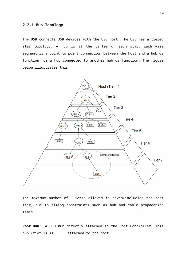
2.2.1 Bus Topology
The USB connects USB devices with the USB host. The USB has a tiered star topology. A hub is at
the center of each star. Each wire segment is a point to point connection between the host and a hub or
function, or a hub connected to another hub or function. The figure below illustrates this.
The maximum number of 'Tiers' allowed is seven(including the root tier) due to timing constraints
such as hub and cable propagation times.
Root Hub: A USB hub directly attached to the Host Controller. This hub (tier 1) is
attached to the host.
Hub: A USB device that provides additional connections to the USB.
Hub Tier: One plus the number of USB links in a communication path between the host
and a function.

9
2.2.1.1 USB Host
There is only one host in any USB system. The USB interface to the host computer system is referred
to as the Host Controller. The Host Controller may be implemented in a combination of hardware,
firmware, or software. A root hub is integrated within the host system to provide one or more
attachment points.
2.2.1.2 USB Devices
USB devices are one of the following:
Hubs, which provide additional attachment points to the USB
Functions, which provide capabilities to the system, such as an ISDN connection, a digital
joystick, or speakers
USB devices present a standard USB interface in terms of the following:
Their comprehension of the USB protocol
Their response to standard USB operations, such as configuration and reset
Their standard capability descriptive information
2.3 Physical Interface
The physical interface consists of :
Electrical Specifications for the bus.
Mechanical Specifications for the bus.
10
2.3.1 Electrical
The USB cable is a four wire cable, as shown in the figure below.
There are three data rates:
The USB high-speed signalling bit rate is 480 Mb/s.
The USB full-speed signalling bit rate is 12 Mb/s. : PIC18F4550 operates at this data rate in
Full Speed Mode.
A limited capability low-speed signalling mode is also defined at 1.5 Mb/s.
USB 2.0 host controllers and hubs provide capabilities so that full-speed and low-speed data can be
transmitted at high-speed between the host controller and the hub, but transmitted between the hub
and the device at full-speed or low-speed. This capability minimizes the impact that full-speed and
low-speed devices have upon the bandwidth available for high-speed devices such as HDDs etc.
The low-speed mode is defined to support a limited number of low-bandwidth devices, such as mice,
because more general use would degrade bus utilization. The clock is transmitted, encoded along with
the differential data. The clock encoding scheme is NRZI* with bit stuffing to ensure adequate
transitions. A SYNC field precedes each packet to allow the receiver(s) to synchronize their bit
recovery clocks.
*Non Return to Zero Invert (NRZI) : A method of encoding serial data in which ones and zeroes are represented by opposite and alternating high and low voltages where there is no return to zero (reference) voltage between encoded bits. Eliminates the need for lock pulses.The cable also carries VBUS and GND wires on each segment to deliver power to devices. VBUS is
nominally +5 V at the source. The USB allows cable segments of variable lengths, up to several

11
meters, by choosing the appropriate conductor gauge to match the specified IR drop and other
attributes such as device power budget and cable flexibility. In order to provide guaranteed input
voltage levels and proper termination impedance, biased terminations are used at each end of the
cable. The terminations also permit the detection of attach and detach at each port and differentiate
between high/full-speed and low-speed devices.
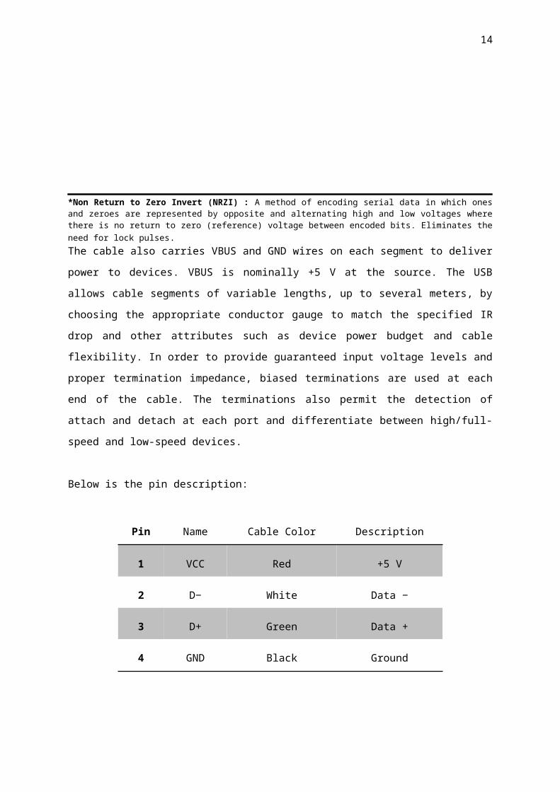
Below is the pin description:
Pin Name Cable Color Description
1 VCC Red +5 V
2 D− White Data −
3 D+ Green Data +
4 GND Black Ground

12
2.3.2 Mechanical
The mechanical specifications for cables for High Speed/Full Speed and Low Speed modes is defined
in this section. All devices have an upstream connection. Upstream and downstream connectors are
not mechanically interchangeable, thus eliminating illegal loopback connections at hubs. The cable
has four conductors: a twisted signal pair of standard gauge and a power pair in a range of permitted
gauges. The connector is four-position, with shielded housing, specified robustness, and ease of
attach-detach characteristics.
The following list explains how the plugs and receptacles can be mated:
Series “A” receptacle mates with a Series “A” plug. Electrically, Series “A” receptacles
function as outputs from host systems and/or hubs.
Series “A” plug mates with a Series “A” receptacle. The Series “A” plug always is oriented
towards the host system.
Series “B” receptacle mates with a Series “B” plug (male). Electrically, Series “B”
receptacles function as inputs to hubs or devices.
Series “B” plug mates with a Series “B” receptacle. The Series “B” plug is always oriented
towards the USB hub or device.

13
2.3.2.1 Cable Specifications
For High/Full Speeds:
High-/full-speed and low-speed cables differ in data conductor arrangement and shielding. Low-speed
recommends, but does not require, use of a cable with twisted data conductors. Low speed
recommends, but does not require, use of a cable with a braided outer shield. High-/full-speed cable
consists of one 28 to 20 AWG non-twisted power pair and one 28 AWG twisted data pair with an
aluminium metalized polyester inner shield, 28 AWG stranded tinned copper drain wire, > 65%
tinned copper wire interwoven (braided) outer shield, and PVC outer jacket. Low-speed cable consists
of one 28 to 20 AWG non-twisted power pair and one 28 AWG data pair (a twist is recommended)
with an aluminium metalized polyester inner shield, 28 AWG stranded tinned copper drain wire and
PVC outer jacket. A > 65% tinned copper wire interwoven (braided) outer shield is recommended.
14
2.4 Power
The specification covers two aspects of power:
Power distribution over the USB deals with the issues of how USB devices consume power
provided by the host over the USB.
Power management deals with how the USB System Software and devices fit into the host-
based power management system.
Each USB segment provides a limited amount of power over the cable. The host supplies power for
use by USB devices that are directly connected. In addition, any USB device may have its own power
supply. USB devices that rely totally on power from the cable are called bus-powered devices. In
contrast, those that have an alternate source of power are called self-powered devices. A hub also
supplies power for its connected USB devices.
A USB host may have a power management system that is independent of the USB. The USB
System Software interacts with the host’s power management system to handle system power events
such as suspend or resume. Additionally, USB devices typically implement additional power
management features that allow them to be power managed by system software. The power
distribution and power management features of the USB allow it to be designed into power sensitive
systems such as battery-based notebook computers

15
2.5 Bus Protocol
2.5.1 Terminology
1. Polled Bus: USB is a polled bus, no interrupts are present. Basically it means that if USB
device has some information to pass to HC(Host Controller), it has to wait till HC polls
it. Asking multiple devices, one at a time, if they have any data to transmit.
2. Host: The host computer system where the USB Host Controller is installed. This includes
the host hardware platform (CPU, bus, etc.) and the operating system in use.
3. Host Controller: The Host's USB Interface
4. Endpoint Direction: The direction of data transfer on the USB. The direction can be either
IN or OUT. IN refers to transfers to the host; OUT refers to transfers from the host.
5. Device Address: A seven-bit value representing the address of a device on the USB. The
device address is the default address (00H) when the USB device is first powered or the
device is reset. Devices are assigned a unique device address by the USB System Software.
6. Endpoint Number: A four-bit value between 0H and FH, inclusive, associated with an
endpoint on a USB device.
7. Token Packet: A type of packet that identifies what transaction is to be performed on the
bus.
8. Handshake Packet: A packet that acknowledges or rejects a specific condition. For
examples, see ACK and NAK.
9. Message Pipe: A bi-directional pipe that transfers data using a request/data/status paradigm.
The data has an imposed structure that allows requests to be reliably identified and
communicated.
10. Default Control Pipe: The message pipe created by the USB System Software to pass
control and status information between the host and a USB device’s endpoint zero.
11. Stream Pipes: A pipe that transfers data as a stream of samples with no defined USB
structure.
12. NAK: Negative Acknowledgement

16
The USB is a polled bus. The Host Controller initiates all data transfers. Most bus transactions
involve the transmission of up to three packets. Each transaction begins when the Host Controller, on
a scheduled basis, sends a USB packet describing the type and direction of transaction, the USB
device address, and endpoint number. This packet is referred to as the “token packet.” The USB
device that is addressed selects itself by decoding the appropriate address fields. In a given
transaction, data is transferred either from the host to a device or from a device to the host. The
direction of data transfer is specified in the token packet. The source of the transaction then sends a
data packet or indicates it has no data to transfer. The destination, in general, responds with a
handshake packet indicating whether the transfer was successful. Some bus transactions between host
controllers and hubs involve the transmission of four packets. These types of transactions are used to
manage the data transfers between the host and full-/low- speed devices. The USB data transfer model
between a source or destination on the host and an endpoint on a device is referred to as a pipe. There
are two types of pipes: stream and message. Stream data has no USB-defined structure, while message
data does. Additionally, pipes have associations of data bandwidth, transfer service type, and endpoint
characteristics like directionality and buffer sizes. Most pipes come into existence when a USB device
is configured. One message pipe, the Default Control Pipe, always exists once a device is powered, in
order to provide access to the device’s configuration, status, and control information. The transaction
schedule allows flow control for some stream pipes. At the hardware level, this prevents buffers from
underrun or overrun situations by using a NAK+ handshake to throttle the data rate. When NAKed, a
transaction is retried when bus time is available. The flow control mechanism permits the construction
of flexible schedules that accommodate concurrent servicing of a heterogeneous mix of stream pipes.
Thus, multiple stream pipes can be serviced at different intervals and with packets of different sizes.
17
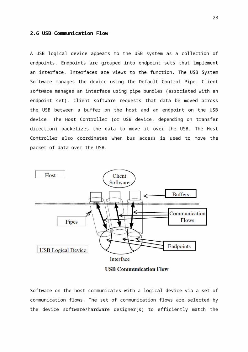
2.6 USB Communication Flow
A USB logical device appears to the USB system as a collection of endpoints. Endpoints are grouped
into endpoint sets that implement an interface. Interfaces are views to the function. The USB System
Software manages the device using the Default Control Pipe. Client software manages an interface
using pipe bundles (associated with an endpoint set). Client software requests that data be moved
across the USB between a buffer on the host and an endpoint on the USB device. The Host Controller
(or USB device, depending on transfer direction) packetizes the data to move it over the USB. The
Host Controller also coordinates when bus access is used to move the packet of data over the USB.
Software on the host communicates with a logical device via a set of communication flows. The set of
communication flows are selected by the device software/hardware designer(s) to efficiently match
the communication requirements of the device to the transfer characteristics provided by the USB.

18
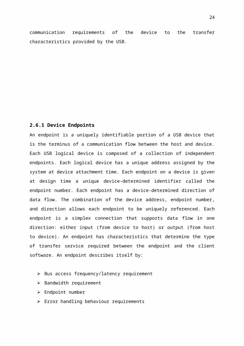
2.6.1 Device Endpoints
An endpoint is a uniquely identifiable portion of a USB device that is the terminus of a
communication flow between the host and device. Each USB logical device is composed of a
collection of independent endpoints. Each logical device has a unique address assigned by the system
at device attachment time. Each endpoint on a device is given at design time a unique device-
determined identifier called the endpoint number. Each endpoint has a device-determined direction of
data flow. The combination of the device address, endpoint number, and direction allows each
endpoint to be uniquely referenced. Each endpoint is a simplex connection that supports data flow in
one direction: either input (from device to host) or output (from host to device). An endpoint has
characteristics that determine the type of transfer service required between the endpoint and the client
software. An endpoint describes itself by:
Bus access frequency/latency requirement
Bandwidth requirement
Endpoint number
Error handling behaviour requirements
Maximum packet size that the endpoint is capable of sending or receiving
The transfer type(described later) for the endpoint
The direction in which data is transferred between the endpoint and the host.
Endpoints other than those with endpoint number zero are in an unknown state before being
configured and may not be accessed by the host before being configured.
2.6.2 Endpoint Zero Requirements
All USB devices are required to implement a default control method that uses both the input and
output endpoints with endpoint number zero. The USB System Software uses this default control
method to initialize and generically manipulate the logical device (e.g., to configure the logical
device) as the Default Control Pipe. The Default Control Pipe provides access to the device’s
configuration information and allows generic USB status and control access. The Default Control
Pipe supports control transfers as defined in Section 5.5. The endpoints with endpoint number zero are
always accessible once a device is attached, powered, and has received a bus reset. A USB device that
is capable of operating at high-speed must have a minimum level of support for operating at full-
speed. When the device is attached to a hub operating in full-speed, the device must:
Be able to reset successfully at full-speed

19
Respond successfully to standard requests: set_address, set_configuration, get_descriptor for
device and configuration descriptors, and return appropriate information
The high-speed device may or may not be able to support its intended functionality when operating at
fullspeed.
2.6.3 Non-endpoint Zero Requirements
Functions can have additional endpoints as required for their implementation. Low-speed functions
are limited to two optional endpoints beyond the two required to implement the Default Control Pipe.
Fullspeed devices can have additional endpoints only limited by the protocol definition (i.e., a
maximum of 15 additional input endpoints and 15 additional output endpoints). Endpoints other than
those for the Default Control Pipe cannot be used until the device is configured as a normal part of the
device configuration process .
2.6.4 Pipes
A USB pipe is an association between an endpoint on a device and software on the host. Pipes
represent the ability to move data between software on the host via a memory buffer and an endpoint
on a device. There are two mutually exclusive pipe communication modes:
Stream: Data moving through a pipe has no USB-defined structure
Message: Data moving through a pipe has some USB-defined structure
The USB does not interpret the content of data it delivers through a pipe. Even though a message pipe
requires that data be structured according to USB definitions, the content of the data is not interpreted
by the USB. Additionally, pipes have the following associated with them:
A claim on USB bus access and bandwidth usage.
A transfer type.
The associated endpoint’s characteristics, such as directionality and maximum data payload
sizes. The data payload is the data that is carried in the data field of a data packet within a bus
transaction.
The pipe that consists of the two endpoints with endpoint number zero is called the Default Control
Pipe. This pipe is always available once a device is powered and has received a bus reset. Other pipes
come into existence when a USB device is configured. The Default Control Pipe is used by the USB
System Software to determine device identification and configuration requirements and to configure
the device. The Default Control Pipe can also be used by device-specific software after the device is
configured. The USB System Software retains “ownership” of the Default Control Pipe and mediates
use of the pipe by other client software.

20
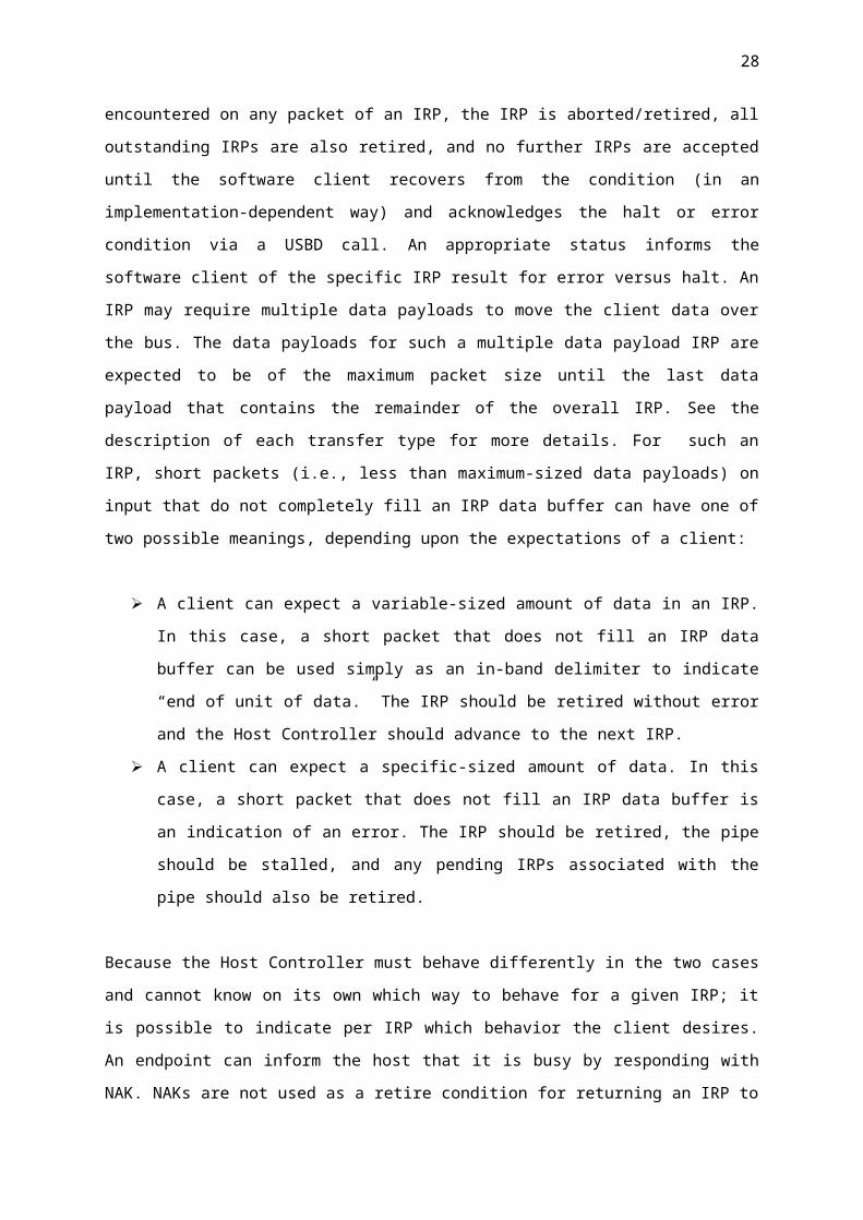
A software client normally requests data transfers via I/O Request Packets (IRPs) to a pipe
and then either waits or is notified when they are completed. Details about IRPs are defined in an
operating system specific manner. This specification uses the term to simply refer to an identifiable
request by a software client to move data between itself (on the host) and an endpoint of a device in
an appropriate direction. A software client can cause a pipe to return all outstanding IRPs if it desires.
The software client is notified that an IRP has completed when the bus transactions associated
with it have completed either successfully or due to errors. If there are no IRPs pending or in progress
for a pipe, the pipe is idle and the Host controller will take no action with regard to the pipe; i.e., the
endpoint for such a pipe will not see any bus transactions directed to it. The only time bus activity is
present for a pipe is when IRPs are pending for that pipe. If a non-isochronous pipe encounters a
condition that causes it to send a STALL to the host or three bus errors are encountered on any packet
of an IRP, the IRP is aborted/retired, all outstanding IRPs are also retired, and no further IRPs are
accepted until the software client recovers from the condition (in an implementation-dependent way)
and acknowledges the halt or error condition via a USBD call. An appropriate status informs the
software client of the specific IRP result for error versus halt. An IRP may require multiple data
payloads to move the client data over the bus. The data payloads for such a multiple data payload IRP
are expected to be of the maximum packet size until the last data payload that contains the remainder
of the overall IRP. See the description of each transfer type for more details. For such an IRP, short
packets (i.e., less than maximum-sized data payloads) on input that do not completely fill an IRP data
buffer can have one of two possible meanings, depending upon the expectations of a client:
A client can expect a variable-sized amount of data in an IRP. In this case, a short packet that
does not fill an IRP data buffer can be used simply as an in-band delimiter to indicate “end of
unit of data.” The IRP should be retired without error and the Host Controller should advance
to the next IRP.
A client can expect a specific-sized amount of data. In this case, a short packet that does not
fill an IRP data buffer is an indication of an error. The IRP should be retired, the pipe should
be stalled, and any pending IRPs associated with the pipe should also be retired.
Because the Host Controller must behave differently in the two cases and cannot know on its own
which way to behave for a given IRP; it is possible to indicate per IRP which behavior the client
desires. An endpoint can inform the host that it is busy by responding with NAK. NAKs are not used
as a retire condition for returning an IRP to a software client. Any number of NAKs can be
encountered during the processing of a given IRP. A NAK response to a transaction does not
constitute an error and is not counted as one of the three errors described above.
2.6.5 Stream Pipes

21
Stream pipes deliver data in the data packet portion of bus transactions with no USB-required
structure on the data content. Data flows in at one end of a stream pipe and out the other end in the
same order. Stream pipes are always uni-directional in their communication flow. Data flowing
through a stream pipe is expected to interact with what the USB believes is a single client. The USB
System Software is not required to provide synchronization between multiple clients that may be
using the same stream pipe. Data presented to a stream pipe is moved through the pipe in sequential
order: first-in, first-out. A stream pipe to a device is bound to a single device endpoint number in the
appropriate direction (i.e., corresponding to an IN or OUT token as defined by the protocol layer).
The device endpoint number for the opposite direction can be used for some other stream pipe to the
device. Stream pipes support bulk, isochronous, and interrupt transfer types, which are explained in
later sections.
2.6.6 Message Pipes
Message pipes interact with the endpoint in a different manner than stream pipes. First, a request is
sent to the USB device from the host. This request is followed by data transfer(s) in the appropriate
direction. Finally, a Status stage follows at some later time. In order to accommodate the
request/data/status paradigm, message pipes impose a structure on the communication flow that
allows commands to be reliably identified and communicated. Message pipes allow communication
flow in both directions, although the communication flow may be predominately one way. The
Default Control Pipe is always a message pipe. The USB System Software ensures that multiple
requests are not sent to a message pipe concurrently. A device is required to service only a single
message request at a time per message pipe. Multiple software clients on the host can make requests
via the Default Control Pipe, but they are sent to the device in a first-in, first-out order. A device can
control the flow of information during the Data and Status stages based on its ability to respond to the
host transactions (refer to Chapter 8 for more details).
A message pipe will not normally be sent the next message from the host until the current message’s
processing at the device has been completed. However, there are error conditions whereby a message
transfer can be aborted by the host and the message pipe can be sent a new message transfer
prematurely (from the device’s perspective). From the perspective of the software manipulating a
message pipe, an error on some part of an IRP retires the current IRP and all queued IRPs. The
software client that requested the IRP is notified of the IRP completion with an appropriate error
indication. A message pipe to a device requires a single device endpoint number in both directions (IN
and OUT tokens). The USB does not allow a message pipe to be associated with different endpoint
numbers for each direction.

22
2.7 Transfer Types
The USB transports data through a pipe between a memory buffer associated with a software client on
the host and an endpoint on the USB device. Data transported by message pipes is carried in a USB-
defined structure, but the USB allows device-specific structured data to be transported within the
USB-defined message data payload. The USB also defines that data moved over the bus is packetized
for any pipe (stream or message), but ultimately the formatting and interpretation of the data
transported in the data payload of a bus transaction is the responsibility of the client software and
function using the pipe. However, the USB provides different transfer types that are optimized to
more closely match the service requirements of the client software and function using the pipe. An
IRP uses one or more bus transactions to move information between a software client and its function.
Each transfer type determines various characteristics of the communication flow including the
following:
Data format imposed by the USB
Direction of communication flow
Packet size constraints
Bus access constraints
Latency constraints
Required data sequences
Error handling
The designers of a USB device choose the capabilities for the device’s endpoints. When a pipe is
established for an endpoint, most of the pipe’s transfer characteristics are determined and remain fixed
for the lifetime of the pipe. Transfer characteristics that can be modified are described for each
transfer type. The USB defines four transfer types:
Control Transfers: Bursty, non-periodic, host software-initiated request/response
communication, typically used for command/status operations.
Isochronous Transfers: Periodic, continuous communication between host and device,
typically used for time-relevant information. This transfer type also preserves the concept of
time encapsulated in the data. This does not imply, however, that the delivery needs of such
data is always time-critical.
Interrupt Transfers: Low-frequency, bounded-latency communication.
Bulk Transfers: Non-periodic, large-packet bursty communication, typically used for data
that can use any available bandwidth and can also be delayed until bandwidth is available.
23
3.0 Getting Started
Programming the Blank PIC
To program the blank PIC we need the correct software and hardware counterparts. First the
bootloader is burnt onto the PIC which configures the USB interface after which the PIC can be
reprogrammed using the USB interface. To burn this bootloader we need a standalone programmer.
Once the bootloader is burnt on the blank PIC there is NO NEED for a standalone programmer as the
bootloader configures the USB interface.
3.1 Hardware
Devices called "programmers" are traditionally used to get program code into the target PIC. Most
PICs that Microchip currently sell feature ICSP (In Circuit Serial Programming) and/or LVP (Low
Voltage Programming) capabilities, allowing the PIC to be programmed while it is sitting in the target
circuit. ICSP programming is performed using two pins, clock and data, while a high voltage (12V) is
present on the Vpp/MCLR pin. Low voltage programming dispenses with the high voltage, but
reserves exclusive use of an I/O pin and can therefore be disabled to recover the pin for other uses
(once disabled it can only be re-enabled using high voltage programming).
There are many programmers for PIC microcontrollers, ranging from the extremely simple designs
which rely on ICSP to allow direct download of code from a host computer, to intelligent
programmers that can verify the device at several supply voltages. Many of these complex
programmers use a pre-programmed PIC themselves to send the programming commands to the PIC
that is to be programmed. The intelligent type of programmer is needed to program earlier PIC models
(mostly EPROM type) which do not support in-circuit programming.
Many of the higher end flash based PICs can also self-program (write to their own program memory).
Demo boards are available with a small bootloader factory programmed that can be used to load user
programs over an interface such as RS-232 or USB, thus obviating the need for a programmer device.
Alternatively there is bootloader firmware available that the user can load onto the PIC using ICSP.
The advantages of a bootloader over ICSP is the far superior programming speeds, immediate
program execution following programming, and the ability to both debug and program using the
same cable. There are two hardware circuits to be assembled namely the programmer and the
PICDEM FS Demo board. The circuits were assembled first on breadboard to validate the
24
implementation, then it was made permanent on a vectorboard. Although the programmer circuit was
made on breadboard only due to the reasons stated in next section.
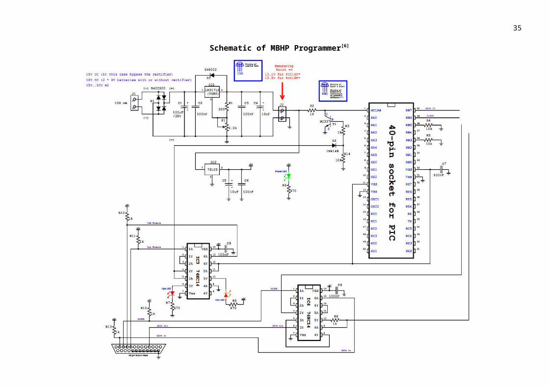
3.1.1 Programmer[6][7]
The programmer we used MBHP Burner is compatible with PIC18F4550 and other types of PICs. It
is a parallel port programmer and opensource. The programmer was made on breadboard due to
paucity of time and one-time usage(although soldering of the components is recommended). The
schematic is presented on the next page. The bootloader can be permanently stored in the EEPROM
of the PIC18F4550 using the programming voltage of 12V. This voltage is provided by the 15V DC
Adapter.

25
Schematic of MBHP Programmer[6]

26
Parallel Port Programmer
Power LED Status LEDs
15V DC Adapter Parallel Port(Male 25-Pin) Programmer

27
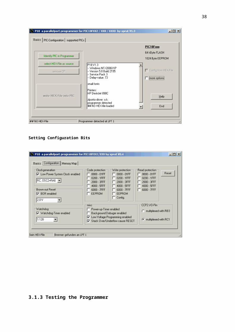
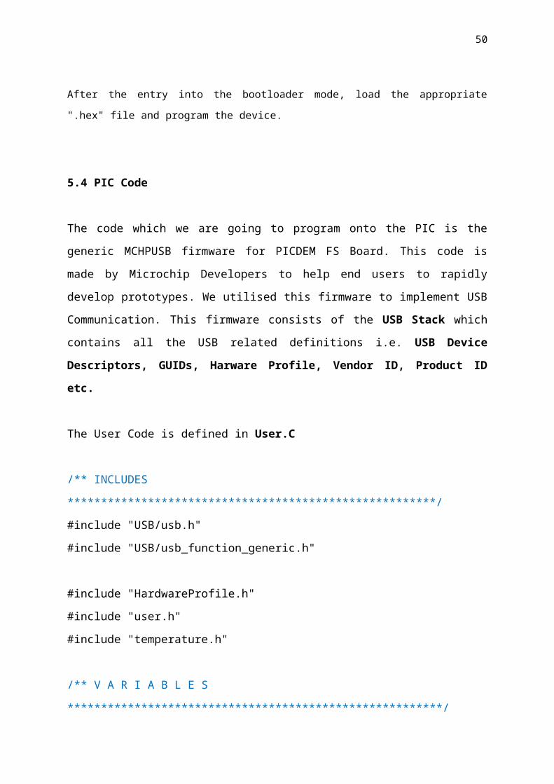
3.1.2 Software for Programmer[9]
The software compatible with MBHP Burner module is P18 which has been provided by a German
programmer. P18 is compatible with many PIC architectures.
Setting Configuration Bits
28
3.1.3 Testing the Programmer
Never plug a PIC into the socket if you haven't done the initial hardware checks. Also,
do not plug in a PIC if the RED or YELLOW LED is lit, because the PIC could be
permanently damaged if the pins are getting in touch with an active Vdd/Vpp level
before the Vss pins are connected to ground!
Connect the external power supply, the green power LED should light up
Adjust the programming voltage with pot P1 and measure it at J2:
12.5V for a PIC18F or PIC16F...A device
13.1V for a PIC16F... device
Connect MBHP_BURNER to the parallel port
Start the P18 programming software
If the "programmer detected" message doesn't appear, you can check the parallel port with a
simple test adapter which is described in the help file of P18.

29
Change to the Options->Hardware menu, select the "Tait classic, Brenner5, Brenner3" mode
switch on Vpp - the red LED should go on. Measure the voltage at the MCLR# pin, it should be
the same like adjusted before
switch off Vpp - the red LED should go off, the voltage at MCLR# should turn to 0V
switch on Vdd - the yellow LED should go on. Measure the voltage at the Vdd pins, it should be
5V
switch off Vdd - the yellow LED should go off, the voltage at the Vdd pins should be 0V
do the same checks with the clock and data pin (RB6 and RB7). The voltage should switch
between 0V and 5V
Click on the "Data In" button - Data In should get the same value like selected with one of the
above sData buttons
If these tests are passing, Vpp and Vdd should be switched off. Thereafter insert the PIC into the
socket.
Click on "Identify PIC in Programmer" -- the right PIC type number should appear in the message
screen

30
Load the .hex file i.e. MCHPUSB Bootloader and click in "write HEX-file into PIC". P18 will
program and verify the memory image. An OK message will appear once this is done.
3.1.4 Troubleshooting
If the PIC cannot be detected, or if the programming procedure works unstable, a printer or
scanner driver which is running in background could be the reason - the driver has to be disabled
in this case.
Such an issue could also be related to the interface and PIC timing settings. They can be changed
under Options->Timing. In order to check the relevance, you could move the sliders to the
slowest timings first - once you were able to program the PIC with success, you can try to find the
best values.
Check the cable to the parallel port.

31
4.0 PICDEM FS Board
This project is based on PICDEM FS Development Board. This board utilises the USB bootloader
interface and other Microchip Design Tools to rapidly develop the User Program and implement it on
the board.
4.1 Hardware[7]
This circuit is used as a reference. As it is evident, the circuit has very low component count and
combined with USB capability it is a complete platform for our design.

32
Circuit Assembled on Vero board
USB CableToggle Switches for selection b/w Pot,LM35 &
Function
USB Status LEDS
Potentiometer
RESET Switch
PROGRAM Switch
For external Function Generator
PIC18F4550
LM 35 Temperature

33
5.0 Getting Started with the USB Programming
After the bootloader has been successfully burnt on the PIC18F4550, it now time to program the PIC
using the USB programming tools provided by Microchip. The tools can be downloaded freely from
their website.[8]
5.1 MPLAB IDE[8]
MPLAB Integrated Development Environment (IDE) is a free, integrated toolset for the development
of embedded applications employing Microchip's PIC® and dsPIC® microcontrollers. MPLAB IDE
runs as a 32-bit application on MS Windows®, is easy to use and includes a host of free software
components for fast application development and super-charged debugging. MPLAB IDE also serves
as a single, unified graphical user interface for additional Microchip and third party software and
hardware development tools. Moving between tools is a snap, and upgrading from the free software
simulator to hardware debug and programming tools is done in a flash because MPLAB IDE has the
same user interface for all tools.
MPLAB C Compilers, the highly optimized compilers for the PIC18 series microcontrollers,
high performance PIC24 MCUs, dsPIC digital signal controllers and PIC32MX MCUs. Or, use one of
the many products from third party language tools vendors. Most integrate into MPLAB IDE to
function transparently from the MPLAB project manager, editor and debugger.

34
OutputProgram Memory
35
5.2 USB Driver Installation
After successful programming, connect your device to the PC's USB port (if not already connected). Now Windows should detect a new USB device. If it asks for the driver, choose the driver location manually and navigate to the driver directory which is located in the Microchip's Applications Library installation directory in the subdirectory
USB Tools\MCHPUSB Custom Driver\MCHPUSB Driver\Release.
5.3 Bootloader PC Software - "PDFSUSB.exe"
The bootloader PC software PDFSUSB.exe is located in the directory USB Tools\Pdfsusb. The tool itself is self explaining.
NOTE: To get the PIC into bootloader mode, while Pressing Down the RESET Switch, press
and release the PROGRAM Switch.
After the entry into the bootloader mode, load the appropriate ".hex" file and program the device.

36
5.4 PIC Code
The code which we are going to program onto the PIC is the generic MCHPUSB firmware
for PICDEM FS Board. This code is made by Microchip Developers to help end users to
rapidly develop prototypes. We utilised this firmware to implement USB Communication.
This firmware consists of the USB Stack which contains all the USB related definitions i.e.
USB Device Descriptors, GUIDs, Harware Profile, Vendor ID, Product ID etc.
The User Code is defined in User.C
/** INCLUDES *******************************************************/
#include "USB/usb.h"
#include "USB/usb_function_generic.h"
#include "HardwareProfile.h"
#include "user.h"
#include "temperature.h"
/** V A R I A B L E S
********************************************************/
#pragma udata
BYTE old_sw2,old_sw3;
BYTE counter;
BYTE trf_state;
BYTE temp_mode;
#if defined(__18F14K50) || defined(__18F13K50) || defined(__18LF14K50) ||
defined(__18LF13K50)
#pragma udata usbram2
#elif defined(__18F2455) || defined(__18F2550) || defined(__18F4455) ||
defined(__18F4550)\
|| defined(__18F2458) || defined(__18F2453) || defined(__18F4558) || defined(__18F4553)
#pragma udata USB_VARIABLES=0x500
#elif defined(__18F4450) || defined(__18F2450)

37
#pragma udata USB_VARIABLES=0x480
#else
#pragma udata
#endif
DATA_PACKET INPacket;
DATA_PACKET OUTPacket;
#pragma udata
BYTE pTemp; // Pointer to current logging position, will
// loop to zero once the max index is reached
BYTE valid_temp; // Keeps count of the valid data points
WORD temp_data[30]; // 30 points of data
USB_HANDLE USBGenericOutHandle = 0;
USB_HANDLE USBGenericInHandle = 0;
BOOL blinkStatusValid = TRUE;
// Timer0 - 1 second interval setup.
// Fosc/4 = 12MHz
// Use /256 prescalar, this brings counter freq down to 46,875 Hz
// Timer0 should = 65536 - 46875 = 18661 or 0x48E5
#define TIMER0L_VAL 0xE5
#define TIMER0H_VAL 0x48
/** P R I V A T E P R O T O T Y P E S ***************************************/
void BlinkUSBStatus(void);
BOOL Switch2IsPressed(void);
BOOL Switch3IsPressed(void);
void ResetTempLog(void);
WORD_VAL ReadPOT(void);
void ServiceRequests(void);
38
/** D E C L A R A T I O N S **************************************************/
#pragma code
void UserInit(void)
{
mInitAllLEDs();
mInitAllSwitches();
old_sw2 = sw2;
old_sw3 = sw3;
mInitPOT();
#if defined(__18CXX)
/* Init Timer0 for data logging interval (every 1 second) */
T0CON = 0b10010111;
/* Timer0 is already enabled by default */
#elif defined(__C30__)
#endif
blinkStatusValid = TRUE;
}//end UserInit
/
***************************************************************************
***
* Function: void ProcessIO(void)
*
* PreCondition: None
*
* Input: None

39
*
* Output: None
*
* Side Effects: None
*
* Overview: This function is a place holder for other user routines.
* It is a mixture of both USB and non-USB tasks.
*
* Note: None
***************************************************************************
**/
void ProcessIO(void)
{
//Blink the LEDs according to the USB device status
if(blinkStatusValid)
{
BlinkUSBStatus();
}
// User Application USB tasks
if((USBDeviceState < CONFIGURED_STATE)||(USBSuspendControl==1)) return;
//respond to any USB commands that might have come over the bus
PollTempOnHPCExplorer();
ServiceRequests();
}//end ProcessIO
/
***************************************************************************
***
* Function: void ResetTempLog(void)

40
*
* PreCondition: None
*
* Input: None
*
* Output: None
*
* Side Effects: pTemp = 0; valid_temp = 0;
*
* Overview: This function resets the temperature logging variables
*
* Note: None
***************************************************************************
**/
/
***************************************************************************
***
* Function: WORD_VAL ReadPOT(void)
*
* PreCondition: None
*
* Input: None
*
* Output: WORD_VAL - the 10-bit right justified POT value
*
* Side Effects: ADC buffer value updated
*
* Overview: This function reads the POT and leaves the value in the
* ADC buffer register
*
* Note: None

41
***************************************************************************
**/
WORD_VAL ReadPOT(void)
{
WORD_VAL w;
#if defined(__18CXX)
mInitPOT();
ADCON0bits.GO = 1; // Start AD conversion
while(ADCON0bits.NOT_DONE); // Wait for conversion
w.v[0] = ADRESL;
w.v[1] = ADRESH;
#elif defined(__C30__) || defined(__C32__)
#if defined(PIC24FJ256GB110_PIM) || defined(PIC24FJ256DA210_DEV_BOARD) ||
defined(PIC24FJ256GB210_PIM)
AD1CHS = 0x5; //MUXA uses AN5
// Get an ADC sample
AD1CON1bits.SAMP = 1; //Start sampling
for(w.Val=0;w.Val<1000;w.Val++); //Sample delay, conversion start automatically
AD1CON1bits.SAMP = 0; //Start sampling
for(w.Val=0;w.Val<1000;w.Val++); //Sample delay, conversion start automatically
while(!AD1CON1bits.DONE); //Wait for conversion to complete
#elif defined(PIC24FJ64GB004_PIM)
AD1CHS = 0x7; //MUXA uses AN7
// Get an ADC sample
AD1CON1bits.SAMP = 1; //Start sampling
for(w.Val=0;w.Val<1000;w.Val++); //Sample delay, conversion start automatically

42
AD1CON1bits.SAMP = 0; //Start sampling
for(w.Val=0;w.Val<1000;w.Val++); //Sample delay, conversion start automatically
while(!AD1CON1bits.DONE); //Wait for conversion to complete
#elif defined(PIC24F_STARTER_KIT)
AD1CHS = 0x0; //MUXA uses AN0
// Get an ADC sample
AD1CON1bits.SAMP = 1; //Start sampling
for(w.Val=0;w.Val<1000;w.Val++); //Sample delay, conversion start automatically
AD1CON1bits.SAMP = 0; //Start sampling
for(w.Val=0;w.Val<1000;w.Val++); //Sample delay, conversion start automatically
while(!AD1CON1bits.DONE); //Wait for conversion to complete
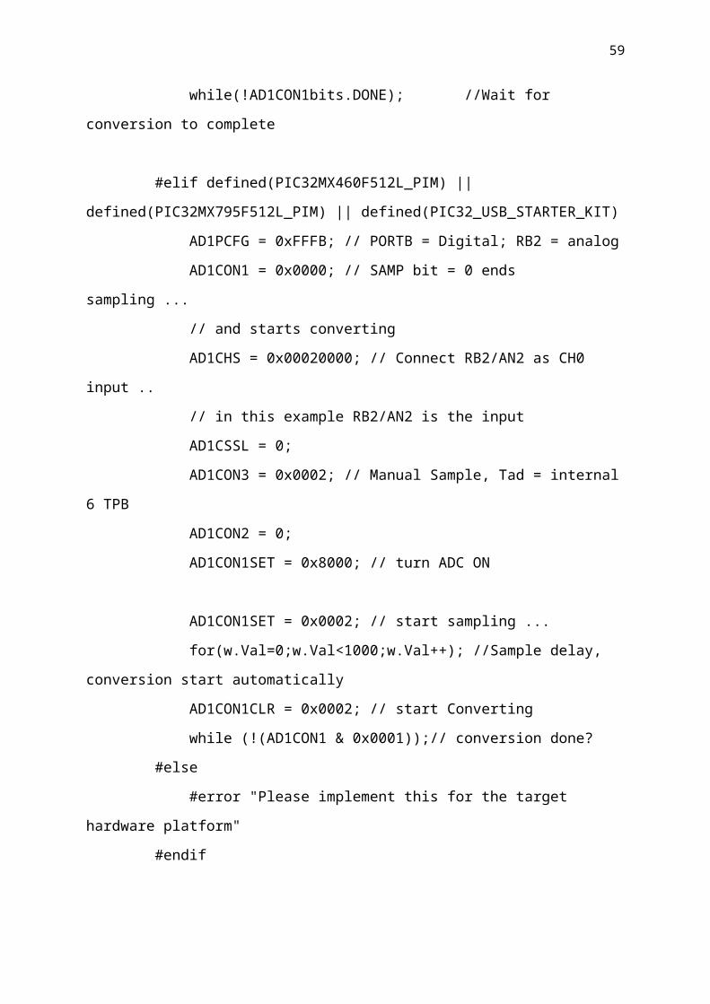
#elif defined(PIC32MX460F512L_PIM) || defined(PIC32MX795F512L_PIM) ||
defined(PIC32_USB_STARTER_KIT)
AD1PCFG = 0xFFFB; // PORTB = Digital; RB2 = analog
AD1CON1 = 0x0000; // SAMP bit = 0 ends sampling ...
// and starts converting
AD1CHS = 0x00020000; // Connect RB2/AN2 as CH0 input ..
// in this example RB2/AN2 is the input
AD1CSSL = 0;
AD1CON3 = 0x0002; // Manual Sample, Tad = internal 6 TPB
AD1CON2 = 0;
AD1CON1SET = 0x8000; // turn ADC ON
AD1CON1SET = 0x0002; // start sampling ...
for(w.Val=0;w.Val<1000;w.Val++); //Sample delay, conversion start automatically
AD1CON1CLR = 0x0002; // start Converting
while (!(AD1CON1 & 0x0001));// conversion done?
#else
#error "Please implement this for the target hardware platform"
#endif

43
w.Val = ADC1BUF0;
#endif
return w;
}//end ReadPOT
/**************************************************************************
* Function: void ServiceRequests(void)
*
* PreCondition: None
*
* Input: None
*
* Output: None
*
* Side Effects: USB traffic can be generated
*
* Overview: This function takes in the commands from the PC from the
* application and executes the commands requested
*
* Note: None
***************************************************************************
**/
void ServiceRequests(void)
{
BYTE index;
//Check to see if data has arrived
if(!USBHandleBusy(USBGenericOutHandle))
{

44
//if the handle is no longer busy then the last
//transmission is complete
counter = 0;
INPacket.CMD=OUTPacket.CMD;
INPacket.len=OUTPacket.len;
//process the command
switch(OUTPacket.CMD)
{
case READ_VERSION:
//dataPacket._byte[1] is len
INPacket._byte[2] = MINOR_VERSION;
INPacket._byte[3] = MAJOR_VERSION;
counter=0x04;
break;
case ID_BOARD:
counter = 0x01;
if(OUTPacket.ID == 0)
{
mLED_3_Off();mLED_4_Off();
}
else if(OUTPacket.ID == 1)
{
mLED_3_Off();mLED_4_On();
}
else if(OUTPacket.ID == 2)
{
mLED_3_On();mLED_4_Off();
}
else if(OUTPacket.ID == 3)
{

45
mLED_3_On();mLED_4_On();
}
else
counter = 0x00;
break;
case UPDATE_LED:
#if defined(PIC18F87J50_PIM) || defined(PIC18F46J50_PIM) ||
defined(PIC18F47J53_PIM)
blinkStatusValid = FALSE;
#endif
// LED1 & LED2 are used as USB event indicators.
if(OUTPacket.led_num == 3)
{
if(OUTPacket.led_status)
{
mLED_3_On();
}
else
{
mLED_3_Off();
}
counter = 0x01;
}//end if
else if(OUTPacket.led_num == 4)
{
if(OUTPacket.led_status)
{
mLED_4_On();
}
else
{
mLED_4_Off();
}

46
counter = 0x01;
}//end if else
break;
case RD_POT: *The Case which is being Utilised*
{
WORD_VAL w;
mInitPOT();
w = ReadPOT();
INPacket._byte[1] = w.v[0];
INPacket._byte[2] = w.v[1];
counter=0x03;
}
break;
case RESET:
Reset();
break;
default:
Nop();
break;
}//end switch()
if(counter != 0)
{
if(!USBHandleBusy(USBGenericInHandle))
{
USBGenericInHandle = USBGenWrite(USBGEN_EP_NUM,
(BYTE*)&INPacket,counter);
}

47
}//end if
//Re-arm the OUT endpoint for the next packet
USBGenericOutHandle = USBGenRead(USBGEN_EP_NUM,
(BYTE*)&OUTPacket,USBGEN_EP_SIZE);
}//end if
}//end ServiceRequests
/********************************************************************
* Function: void BlinkUSBStatus(void)
*
* PreCondition: None
*
* Input: None
*
* Output: None
*
* Side Effects: None
*
* Overview: BlinkUSBStatus turns on and off LEDs
* corresponding to the USB device state.
*
* Note: mLED macros can be found in HardwareProfile.h
* USBDeviceState is declared and updated in
* usb_device.c.
*******************************************************************/
void BlinkUSBStatus(void)
{
static WORD led_count=0;
if(led_count == 0)led_count = 10000U;
led_count--;

48
#define mLED_Both_Off() {mLED_1_Off();mLED_2_Off();}
#define mLED_Both_On() {mLED_1_On();mLED_2_On();}
#define mLED_Only_1_On() {mLED_1_On();mLED_2_Off();}
#define mLED_Only_2_On() {mLED_1_Off();mLED_2_On();}
if(USBSuspendControl == 1)
{
if(led_count==0)
{
mLED_1_Toggle();
if(mGetLED_1())
{
mLED_2_On();
}
else
{
mLED_2_Off();
}
}//end if
}
else
{
if(USBDeviceState == DETACHED_STATE)
{
mLED_Both_Off();
}
else if(USBDeviceState == ATTACHED_STATE)
{
mLED_Both_On();
}
else if(USBDeviceState == POWERED_STATE)
{
mLED_Only_1_On();
}

49
else if(USBDeviceState == DEFAULT_STATE)
{
mLED_Only_2_On();
}
else if(USBDeviceState == ADDRESS_STATE)
{
if(led_count == 0)
{
mLED_1_Toggle();
mLED_2_Off();
}//end if
}
else if(USBDeviceState == CONFIGURED_STATE)
{
if(led_count==0)
{
mLED_1_Toggle();
if(mGetLED_1())
{
mLED_2_Off();
}
else
{
mLED_2_On();
}
}//end if
}//end if(...)
}//end if(UCONbits.SUSPND...)
}//end BlinkUSBStatus
50
/
***************************************************************************
***
* Function: BOOL Switch2IsPressed(void)
*
* PreCondition: None
*
* Input: None
*
* Output: BOOL - TRUE if the SW2 was pressed and FALSE otherwise
*
* Side Effects: None
*
* Overview: returns TRUE if the SW2 was pressed and FALSE otherwise
*
* Note: None
***************************************************************************
**/
BOOL Switch2IsPressed(void)
{
if(sw2 != old_sw2)
{
old_sw2 = sw2; // Save new value
if(sw2 == 0) // If pressed
return TRUE; // Was pressed
}//end if
return FALSE; // Was not pressed
}//end Switch2IsPressed
/
***************************************************************************
***
* Function: BOOL Switch3IsPressed(void)

51
*
* PreCondition: None
*
* Input: None
*
* Output: BOOL - TRUE if the SW3 was pressed and FALSE otherwise
*
* Side Effects: None
*
* Overview: returns TRUE if the SW3 was pressed and FALSE otherwise
*
* Note: None
***************************************************************************
**/
BOOL Switch3IsPressed(void)
{
if(sw3 != old_sw3)
{
old_sw3 = sw3; // Save new value
if(sw3 == 0) // If pressed
return TRUE; // Was pressed
}//end if
return FALSE; // Was not pressed
}//end Switch3IsPressed
/**************************************************************************
* Function: void TXbyte(BYTE data)
*
* PreCondition: None
*

52
* Input: BYTE data - send data to the UART(PIC18 only)
*
* Output: None
*
* Side Effects: None
*
* Overview: sends 'data' over the UART
*
* Note: None
***************************************************************************
**/
void TXbyte(BYTE data)
{
#if defined(__18CXX)
while(TXSTAbits.TRMT==0);
TXREG = data;
#endif
}//end TXbyte
/** EOF user.c
***************************************************************/
The User function is called through "main.c"
void main(void)
#else
int main(void)
#endif
{
InitializeSystem();
#if defined(USB_INTERRUPT)

53
USBDeviceAttach();
#endif
while(1)
{
#if defined(USB_POLLING)
// Check bus status and service USB interrupts.
USBDeviceTasks(); // Interrupt or polling method. If using polling, must call
// this function periodically. This function will take care
// of processing and responding to SETUP transactions
// (such as during the enumeration process when you first
// plug in). USB hosts require that USB devices should accept
// and process SETUP packets in a timely fashion. Therefore,
// when using polling, this function should be called
// frequently (such as once about every 100 microseconds) at any
// time that a SETUP packet might reasonably be expected to
// be sent by the host to your device. In most cases, the
// USBDeviceTasks() function does not take very long to
// execute (~50 instruction cycles) before it returns.
#endif
// Application-specific tasks.
// Application related code may be added here, or in the ProcessIO() function.
ProcessIO();
}//end while
}//end main

54
6.0 MATLAB
MATLAB (for matrix laboratory) is a numerical computing
environment and fourth-generation programming language. Developed
by MathWorks, MATLAB allows matrix manipulations, plotting of
functions and data, implementation of algorithms, creation of user interfaces, and interfacing
with programs written in other languages, including C,C++, and Fortran.
Although MATLAB is intended primarily for numerical computing, an optional toolbox uses
the MuPAD symbolic engine, allowing access to symbolic computing capabilities. An
additional package, Simulink, adds graphical multi-domain simulation and Model-Based
Design for dynamic and embedded systems.
In 2004, MATLAB had around one million users across industry and academia.[2] MATLAB
users come from various backgrounds of engineering, science, and economics. MATLAB is
widely used in academic and research institutions as well as industrial enterprises.
Matlab itself doesnt have a direct interface with USB. The communication is established
using a DLL* (Dynamic Link Library) file. The DLL file contains all the USB related
function definitions which are necessary for communication with the PIC, this dll is needed
to operate the driver for USB i.e. "mchpusb.sys". This DLL can be found in the Microchip
Solutions Directory of the install namely "mchpusbapi.dll" and the corresponding Header
File - "_mpusbapi.h".

55
The DLL defines various functions which are ultimately called through MATLAB to derive
data from them. These functions are defined in the sections below:
As explained in the earlier sections USB data is transmitted on PIPES, to create, open and
use these pipes appropriate functions must be called.
1. First Identify that the USB Device with the correct VID & PID is connected to the
USB Port or not. This is called by a function called:
MPUSBGetDeviceCount(Pchar PVID_PID)
Arguments:
PVID & PID : Input String with the appropriate VID & PID. The format is
"vid_XXXX & pid_YYYY". where xxxx is the value of the
VID & PID is YYYY, both in Hexadecimal.
This function results in an output equal to the number of devices who are assigned the PVID
& VID which is passed as an argument to the function.
2. Second instruction return the output access pipe Endpoint of the assigned VID-
PID combination.
MPUSBOpen(DWORD instance, //Input
PVID_PID PChar, //Input
PEP PChar, //Input
DwDir DWORD, //Input
DwReserved DWORD, //Input
DwReserved DWORD) //Input "Future Use"
This command opens the pipe with the attribute FILE_FLAG_OVERLAPPED contained in
the DLL, this allows MPUSBRead, MPUSBReadInt, MPUSBWrite to be called and have a
time out value.
It is important to understand that the driver is shared by different devices. The number of
total devices connected must be equal or less than the number of all devices currently
connected.

56
Arguments:
PEP: Input: String with the number of endpoint to be opened. The format
is "\\MCHP_EPz" or "\MCHP_EPz" depending on the
programming language.
E.g.:
"\\MCHP_EP1" or "\MCHP_EP1"
This argument can be NULL(Zero) to create ties with no function
endpoints specified.
The Functions that use this argument are : MPUSBRead, MPUSBWrite, MPUSBReadInt.
dwDIR: Specifies the address of Endpoint
Used By: MP_READ: For MPUSBRead and MPUSBReadInt
MP_Write: For MMPUSBWrite
Opens a pipe at a time, dwDir=1 opens the pipe for reading and dwDir=0 opens pipe to write
to the PIC, the result it throws is the number of pipe we assign the operating system.
dwReserved: Not assigned at the moment. The default value is zero.
E.g. :
MPUSBOpen(0,vid_pid, out_pipe, dwDir, 0)
3. The third instruction is related to data read pipe.
MPUSBRead( HANDLE handle, //Input
PVOID pData, //Output
DWORD dwLen, //Input
PLength PDWORD, //Output
DwMilliseconds DWORD //Input
);

57
Arguments:
handle: Input: Identifies the pipe of the Endpoint to be read. The pipe is attached to created with the access attribute MP_READ. In conclusion, "handle" is the number of pipe showed us the previous statement with dwDir = 1.
pData: Output: Pointer to buffer that receives the data read from the pipe. The format of the data is an array of N bytes, where N is the number of bytes that handles the "device" in the arrangement being sent to the PC, usually declared at the beginning of the program.
dwLen: Input: Specifies the number of bytes expected reading from the pipe.
pLength: Output: Pointer to the number of bytes read. MPUSBRead to this zero before any reading or check fails.
dwMilliseconds: Input: Specifies the interval time-out in milliseconds. The function returns if the interval elapses but not
is complete the operation. If dwMilliseconds = 0, the function checks data pipe and returns immediately. If dwMilliseconds is infinite interval time-out never ends.
The typical format of this instruction is: MPUSBRead ( myInPipe,
VarPtr(s(0)),Data_to_be_read, 1000
)
4. To send data to the PIC is in the same way with the statement:
MPUSBWrite( HANDLE handle, / / Input PVOID pData, / / Input DWORD dwLen, / / InputPLength PDWORD, / /OutputDwMilliseconds DWORD
); / / Input
Arguments:
handle: Input: Identifies the pipe of the Endpoint which to write. The pipe is attached to created with the access attribute MP_WRITE. In conclusion, "handle" is

58
the number of pipe that we threw the instruction dwDir previous = 0.
pData: Input: Pointer to buffer containing the data written to the pipe.
The data format is an array of N bytes, where N is the number of bytes that handles The "device" in the settlement received from the PC, usually stated at the
beginning of CIP program.
dwLen: Input: Specifies the number of bytes to be written to the pipe.
pLength: Output: A pointer that provides the number of bytes that are written by calling this function. MPUSBWrite
to set this zero before any reading or check fails.
dwMilliseconds: Input: Specifies the interval time-out in milliseconds. The function returns if the interval elapses but not is complete the operation. If dwMilliseconds = 0, the
function checks data pipe and returns immediately. If dwMilliseconds is infinite interval time-out never ends.
The typical format of instruction is:
MPUSBWrite (myOutPipe, VarPtr (SendData (0)), bytes, VarPtr (bytes), 1000)
5. Finally, it requires a close pipe, because after using them once they are expired, is no longer possible to read/write again. to close just run the command:
MPUSBClose( (HANDLE handle)
handle: Input: Identifies the pipe of the Endpoint to be closed.
The typical format of instruction is: MPUSBClose (myOutPipe)
59

60
6.1 MATLAB CODE :
function [tijd] = USBPIC() loadlibrary mpusbapi _mpusbapi.h alias library; vid_pid_norm = libpointer('int8Ptr',[uint8('vid_04d8&pid_000c') 0]) [PIC_connect] = calllib ('library','MPUSBGetDeviceCount', vid_pid_norm) out_pipe = libpointer ('int8Ptr',[uint8('\MCHP_EP1') 0]) [my_out_pipe] = calllib('library','MPUSBOpen',uint8(0), vid_pid_norm,out_pipe, uint8(0), uint8 (0)) in_pipe = libpointer ('int8Ptr',[uint8('\MCHP_EP1') 0]) [my_in_pipe] = calllib('library','MPUSBOpen',uint8(0), vid_pid_norm,in_pipe, uint8 (1), uint8 (0)) c=1 data_in=uint8([0 0 0 0]); data_out=uint8([55 112 1 0]); timespan=100; ymin=0; ymax=6; tijd(1)=0; h=figure('Color',[0.3 0.3 0.3]); set(h,'KeyPressFcn',@keyHandler); paused=0;display('Press w or s to Zoom In/Out the timespan of the window');display('Press a or z to change the lowerbound of vertical axis');display('Press e or r to change the upperbound of vertical axis');display('Press q to quit');quit=0; while(paused~=1) tic; if(calllib('library', 'MPUSBWrite',my_out_pipe, data_out, uint8(1),uint8(64), uint8(1000))) [Aa, bb, data_in, dd] = calllib('library','MPUSBRead', my_in_pipe,data_in,uint8(3),uint8(64), uint8(1000)); ADCVal=bitshift(double(data_in(3)),8)+double(data_in(2)); adc(c,:)=ADCVal*0.004882; if c>1 tijd(c) = toc; tijd(c)=tijd(c)+tijd(c-1); end if c>timespan plot(tijd(c-timespan:c),adc(c-timespan:c)) xlim([tijd(c-timespan+1) tijd(c)]); else plot(tijd(c),adc(c)) end xlabel('Time Elapsed (sec)'); ylabel('Amplitude'); ylim([ymin ymax]); %Samppersec(c,:)=1/(toc); end c=c+1;

61
pause(0.0000000002) end function keyHandler(src,evnt) if evnt.Character == 'w' timespan=timespan+10; elseif evnt.Character == 's' timespan=max(2,timespan-10); elseif evnt.Character == 'a' ymin=max(0,ymin-10); elseif evnt.Character == 'z' ymin=min(ymax-10,ymin+10); elseif evnt.Character == 'e' ymax=max(ymin+10,ymax-10); elseif evnt.Character == 'r' ymax=ymax+10; elseif evnt.Character == 'p' paused = 1; end end calllib('library','MPUSBClose',my_in_pipe); calllib('library','MPUSBClose',my_out_pipe); unloadlibrary library; end
References
[1] USB-IF : http://www.usb.org/home

62
[2] Ajay Bhatt, inventor of USB : http://edition.cnn.com/2010/TECH/02/04/ajay.bhatt.usb.inventor/index.html
[3] http://www.usb.org/developers/docs/ ; 1394 Newsletter 2 (4): 7–9. April 1998 : http://books.google.com/books?id=fRvbxgH4wmsC&pg=PA7#v=onepage&q&f=false : Page : 8
[4] USB 2.0 Specifications : http://www.usb.org/developers/docs/usb_20_081810.zip : usb_20.pdf : Page : 12
[5] USB 2.0 Specifications : http://www.usb.org/developers/docs/usb_20_081810.zip : usb_20.pdf : Page : 16
[6] Programmer Schematic :http://www.ucapps.de/mbhp_burner.html[7] PIC Hardware: http://www.create.ucsb.edu/~dano/CUI/[8] MPLAB IDE http://www.microchip.com/stellent/idcplg?
IdcService=SS_GET_PAGE&nodeId=1406&dDocName=en010014[9] Programmer Software: http://www.sprut.de/electronic/soft/p18/p18.htm


![Project Report[2]223](https://static.fdocuments.us/doc/165x107/5695d2361a28ab9b029985bb/project-report2223.jpg)


