Project Refurbishments in Australasia · Project Refurbishments in Australasia ... Seismic Design...
23
Project Refurbishments in Australasia Orestes Macchione (HVDC Business Development) IEEE PES General Meeting 2015 Denver (CO), USA 1
Transcript of Project Refurbishments in Australasia · Project Refurbishments in Australasia ... Seismic Design...

Project Refurbishments in Australasia Orestes Macchione (HVDC Business Development) IEEE PES General Meeting 2015 Denver (CO), USA
1

Topics to be covered
• New Zealand Inter-Island Pole III HVDC Link
• Queensland, Australia Powerlink SVCs 1. Nebo SVC 2. Railway SVCs
2

NZ Inter-Island HVDC - Overview • Customer: Transpower NZ • Transmission asset owner and
system operator in New Zealand • Bipole with land- and shore
electrodes • 40 km submarine cable • 570 km overhead line • 220 kV AC / 110 kV AC
• Pole 1 - Mercury Arc Valves • Pole 2 - Thyristor Valves • Pole 3 – LT Thyristors
3

Historical Perspective*
4
Pole 1 – Mercury Arc Valves (1965)
Pole 2 – Thyristors (1992)
* New Zealand Inter Island HVDC Pole 3 Project CIGRE SCB4 Colloquium 2011, Brisbane, Australia 19-21 October 2011. Peter Griffiths, Transpower
Pole 3 – Light Triggered Thyristors (2014)

HVDC link – Initial Pole1 & Pole2 5
BENMORE220 kV
HAYWARDS220 kV
Cable 6
Cable 4
Pole 2 (existing thyristor
Converters 700 MW)
535 km DC line section – South
Island
35 km DC line section
North Island
40 km Cook Strait Cables
+ 270 kV
- 350 kV
Cable 5
HAYWARDS110 kV
C7BENMORE
16 kV
Ground (Earth/Sea) Return Current mode
F479.3 Mvar
79.3 Mvar
F3
F3
F4
106.3 Mvar
106.3 Mvar
C1
60 Mvar
T1
C4C335 Mvar
each
T5
C2 60 Mvar
T2
40 MvarR5
40 Mvar
R1
F2
50.5 Mvar
50.5 Mvar
F1
F247.5 Mvar
47.5 MvarC8
C9
C10Pole 1 assets
Pole 2 assets
VG3
VG4
P1B
VG2
VG1
P1A
F1

HVDC Pole 3 Project - Design 6
Stage 1 - 1,000MW
Stage 2 - 1,200MW
Stage 3 - 1,400MW

Seismic Design Aspect
• Both Converter Stations must have High Level of Seismic Resilience, particularly Haywards which is located only a few hundred meters from an active geological fault line
• Structural diversity between the new Pole 3 and the existing Pole 2 in an attempt to avoid common mode failures
• Seismic isolation of the converter building housing the thyristor valves, converter transformers, and control / auxiliary system
7

Converter Building Seismic Isolation
8
Converter building is seismically isolated using Lead Rubber Bearings with a free oscillation amplitude of ±600mm, effectively decoupling the building from horizontal ground earthquake motion.

Reactor & Bushing 9
• Reactor isolation • Shake table test

Design Coordination between Existing and New Plant
• Arrester arrangement including all existing arresters – V-I characteristics – Protective levels of the new surge arresters
• Existing Pole 1 DC filters, built identical to Pole 2 DC filters
• Various components installed at the DC neutral bus need to be replaced by components with higher rating
10

Reactive Power Control 11

AC Filters
• Overall filter design will ensure that the new AC filters do not cause undue loading of the existing filters during operation
• Wider AC frequency range (+/-2 Hz) for Pole 3 comparing to +/-0.75 Hz for Pole 2
• Triple-tuned AC filters TT11/13/24 • 3rd harmonic filters (ST LO3) will be installed at
Benmore taking potential resonances of pre-existing low order harmonics into account
12

Stability, Modulation, and Frequency Control*
• Supplementary Modulation Controls and Runbacks implemented in the HVDC Control System – Weak AC grid – Increased power transfer capability
• DC current modulation to damp voltage swing • Frequency controls such as Constant Frequency
Control; Frequency Keeping Controller and Wellington Over-Frequency Brake
• Round power mode
13
*1400 MW New Zealand HVDC Upgrade: “Introducing Power Modulation Controls and Round Power Mode” Simon P. Teeuwsen, Geoffrey Love, Richard Sherry, Power and Energy Society General Meeting (PES), 2013 IEEE

Round Power Mode 14
Steady-State Operating Characteristic
PDC
Pref
Bipole PowerPole 2 PowerPole 3 PowerPmin POLE = 35MW
Mon
opol
e Tr
ansi
tion
Leve
l
RP
Tra
nsiti
on L
evel
Pmin RP
Pmin RP
+Pm
in B
P
-Pm
in B
P
Mon
opol
e Tr
ansi
tion
Leve
l
Round Power Operation
Monopolar Operation P3
Bipolar Operation
Monopolar Operation P2
Bipolar Operation
RP
Tra
nsiti
on L
evel

Queensland Australia SVCs - Overview
• Customer: Powerlink • Transmission network
service provider within Queensland
• SVCs (1987) provide voltage support to the electrical railway network
• Two refurbishments 1. Nebo SVC 2. Railway SVCs – Mobile /
containerized solutions
15

Nebo SVC 16
• Rating: 340MW (+260/-80MVAr) / 275kV • Refurbishment of:
– Thyristor switched capacitor (TSC) and thyristor controlled reactor (TCR). Two stages:
• Replace damaged TSC valve first interfacing with old C&P
– Control and Protection System – Converter Cooling System

Railway SVC Mobile Solution
• Task: – Refurbishment of nine SVCs’ valve, cooling and C&P
systems with minimum impact on the ongoing system and train operations
• Solution: – Installation and operation of a mobile SVC system in
parallel to the refurbishment work – Minimum downtime for each station – After finishing each SVC refurbishment, the mobile SVC is
transferred to the next station
17
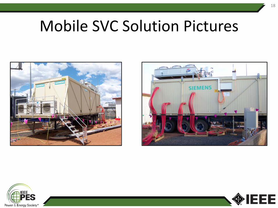
Mobile SVC Solution Pictures 18

Refurbishment Procedure 19
4-6 weeks
2 x 13 hours shifts
3 days
2 x 13 hours shifts 2 days

Site Layout
• Site preparation • Equipment position • Power cable installation
– Six connections total – Each consisting of 6 cables
per bundle in parallel
20

Site Layout Pictures 21
Connections to busbars Cable bundles connected on-site

Concluding Statements
• Refurbishments have their own unique set of challenges – Safety; minimize outages; space constraints,
interfaces with existing equipment, seismic, etc.
• Lifecycle extension of assets without complete replacement of site and equipment – Viable economical solution – Upgrade on performance / availability
22

Thank you
23