Project “ RedEye ”
54
Project “RedEye” University of Central Florida College of Electrical Engineering and Computer Science Senior Design Fall 2011 Group 8 David Morrow Ricardo Rodriguez Shane Theobald Nick Bauer
description
Project “ RedEye ”. University of Central Florida College of Electrical Engineering and Computer Science Senior Design Fall 2011. Group 8 David Morrow Ricardo Rodriguez Shane Theobald Nick Bauer. Motivation. Wanted to gain experience in many different engineering disciplines C# - GUI - PowerPoint PPT Presentation
Transcript of Project “ RedEye ”

Project “RedEye”
University of Central FloridaCollege of Electrical Engineering and Computer Science
Senior Design Fall 2011
Group 8David Morrow
Ricardo RodriguezShane Theobald
Nick Bauer
Wanted to gain experience in many different engineering disciplines◦ C# - GUI◦ Optics – Laser Range Finder◦ Wireless Communication◦ Controlling Peripheral Devices via Microcontroller
Motivation
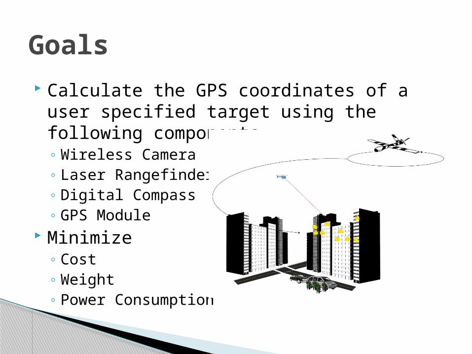
Goals Calculate the GPS coordinates of a user
specified target using the following components.◦ Wireless Camera◦ Laser Rangefinder◦ Digital Compass◦ GPS Module
Minimize◦ Cost◦ Weight◦ Power Consumption
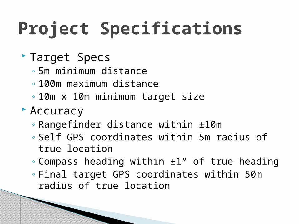
Target Specs◦ 5m minimum distance◦ 100m maximum distance◦ 10m x 10m minimum target size
Accuracy◦ Rangefinder distance within ±10m◦ Self GPS coordinates within 5m radius of true
location◦ Compass heading within ±1° of true heading◦ Final target GPS coordinates within 50m radius of
true location
Project Specifications
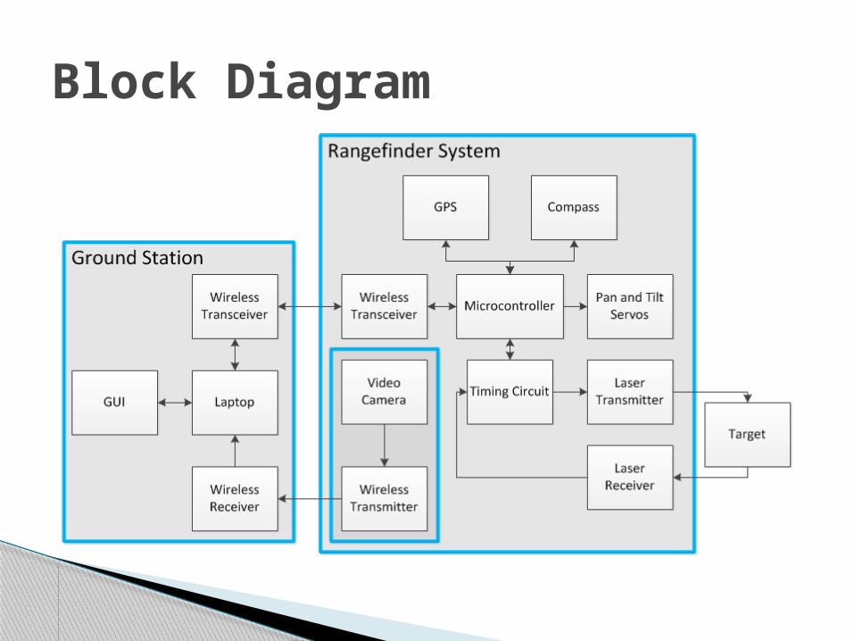
Block Diagram
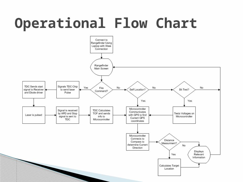
Operational Flow Chart

Methods of Laser Rangefinding◦ Triangulation
Easiest method both conceptually and design Based on geometry Increasingly less accurate as range increases
◦ Interferometry Most accurate method of laser rangefinding Can measure small distances on order of
wavelengths◦ Time-of-flight
Can measure very large distances with great accuracy
This is the approach that we will implement
Rangefinder Subsystem
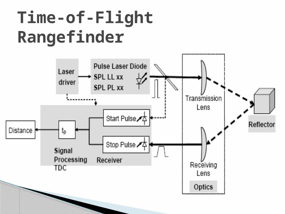
Time-of-Flight Rangefinder
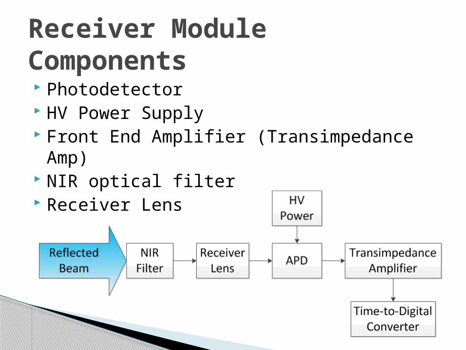
Photodetector HV Power Supply Front End Amplifier (Transimpedance Amp) NIR optical filter Receiver Lens
Receiver Module Components
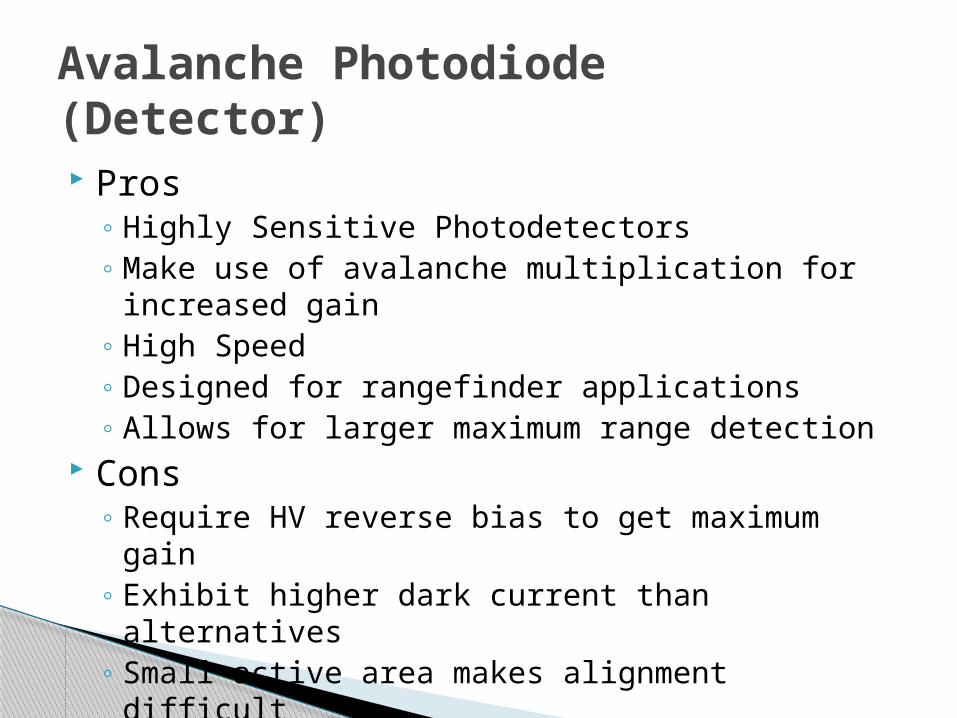
Pros◦ Highly Sensitive Photodetectors◦ Make use of avalanche multiplication for
increased gain◦ High Speed◦ Designed for rangefinder applications◦ Allows for larger maximum range detection
Cons◦ Require HV reverse bias to get maximum gain◦ Exhibit higher dark current than alternatives◦ Small active area makes alignment difficult
Avalanche Photodiode (Detector)
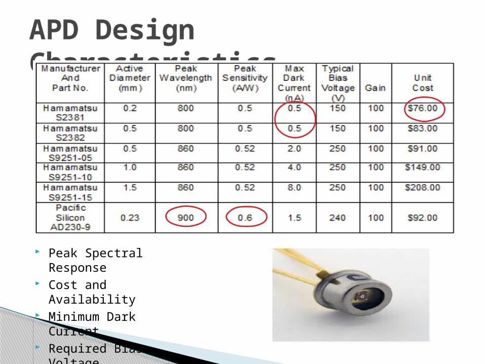
APD Design Characteristics
Peak Spectral Response Cost and Availability Minimum Dark Current Required Bias Voltage
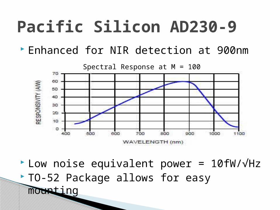
Pacific Silicon AD230-9 Enhanced for NIR detection at 900nm
Low noise equivalent power = 10fW/√Hz TO-52 Package allows for easy mounting
Spectral Response at M = 100

HV Power Supply—EMCO A025P Proportional Input/Output Voltage 250VDC when full 5V input applied Low peak-to-peak ripple (<1%) Maximum Output Current 4mA Low turn on voltage of 0.7V
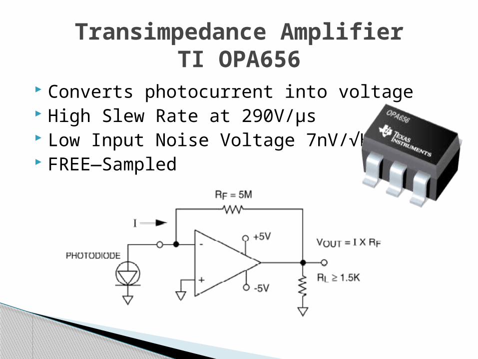
Converts photocurrent into voltage High Slew Rate at 290V/µs Low Input Noise Voltage 7nV/√HZ FREE—Sampled
Transimpedance AmplifierTI OPA656

Receiver System Schematic
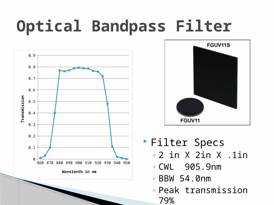
Optical Bandpass Filter
860 870 880 890 900 910 920 930 940 9500
0.1
0.2
0.3
0.4
0.5
0.6
0.7
0.8
0.9
Wavelenth in nm
Tran
smis
sion
Filter Specs◦ 2 in X 2in X .1in◦ CWL 905.9nm◦ BBW 54.0nm◦ Peak transmission
79%

Receiver Prototype Overview
Receiver Electronics
Lens Tube Assembly
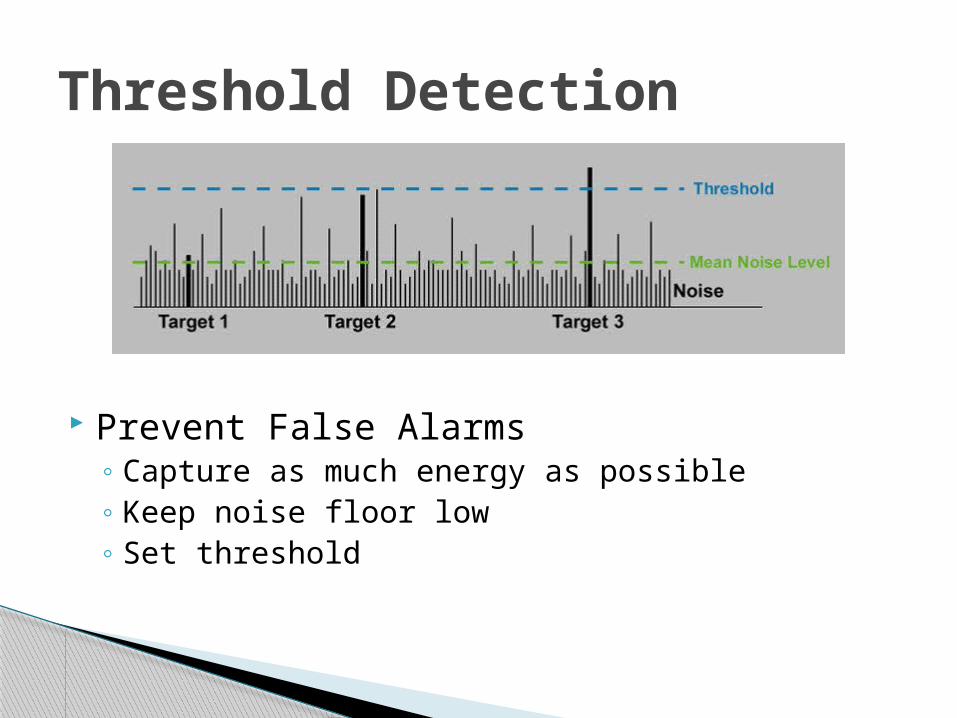
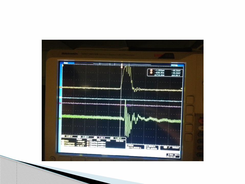
Threshold Detection
Prevent False Alarms◦ Capture as much energy as possible◦ Keep noise floor low◦ Set threshold
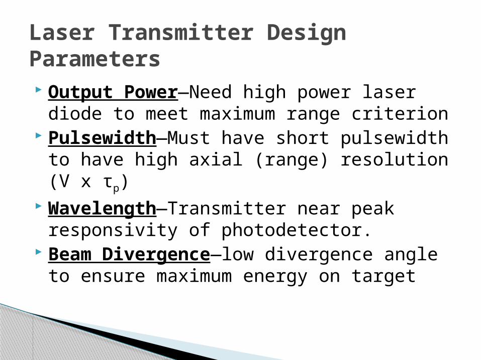
Output Power—Need high power laser diode to meet maximum range criterion
Pulsewidth—Must have short pulsewidth to have high axial (range) resolution (V x τp)
Wavelength—Transmitter near peak responsivity of photodetector.
Beam Divergence—low divergence angle to ensure maximum energy on target
Laser Transmitter Design Parameters
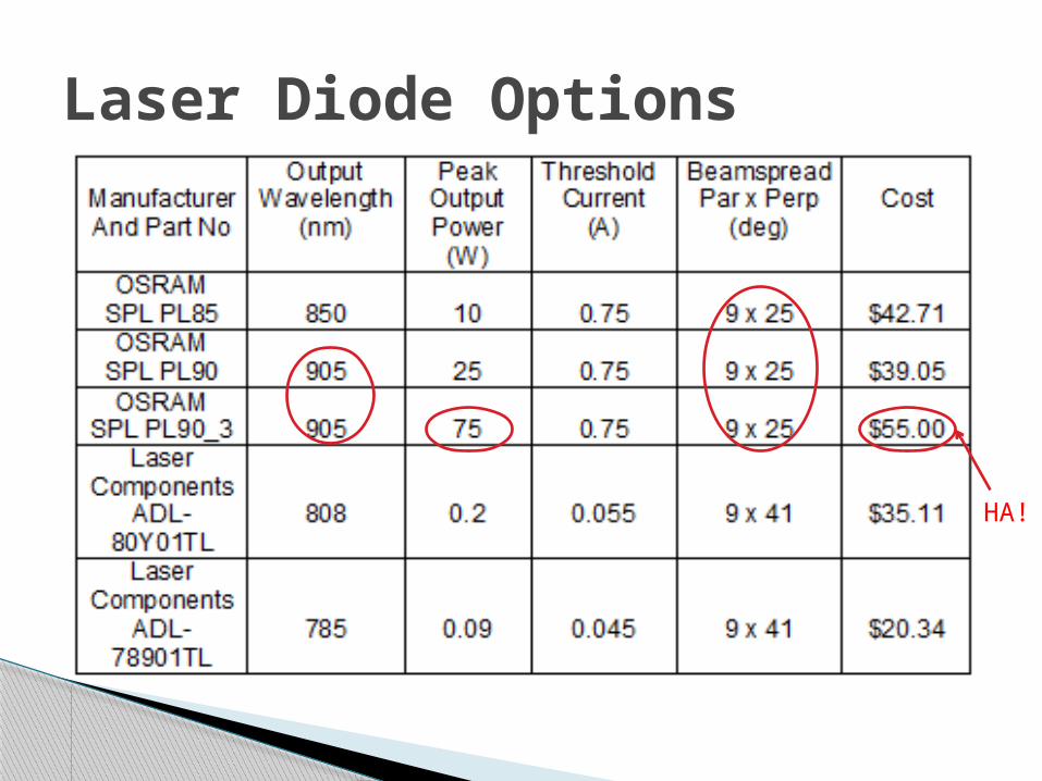
Laser Diode Options
HA!

Laser Diode SPL-PL-90_3
◦ TO-18 Package◦ Divergence 9 x 25 gradient degrees◦ Minimum Rise/Fall time 1ns◦ Threshold Current 0.75A◦ Peak wavelength 905nm◦ Power output 75W◦ Peak Current 40A◦ Typical Voltage 9V◦ Pulsewidth 5-100ns
5.9mm
5mm
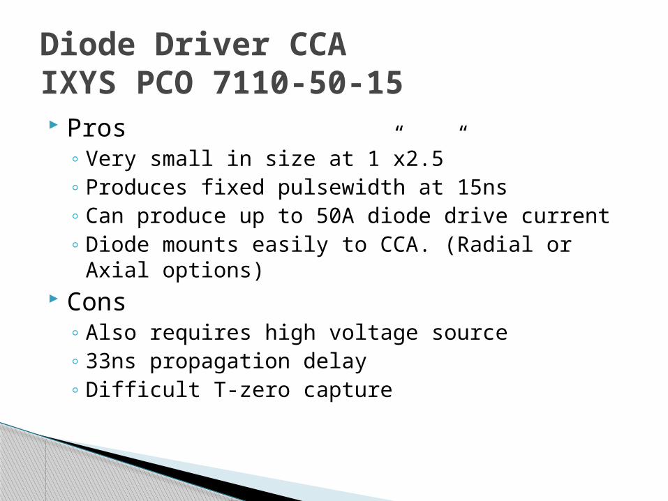
Pros◦ Very small in size at 1”x2.5”◦ Produces fixed pulsewidth at 15ns◦ Can produce up to 50A diode drive current◦ Diode mounts easily to CCA. (Radial or Axial
options) Cons
◦ Also requires high voltage source◦ 33ns propagation delay◦ Difficult T-zero capture
Diode Driver CCAIXYS PCO 7110-50-15
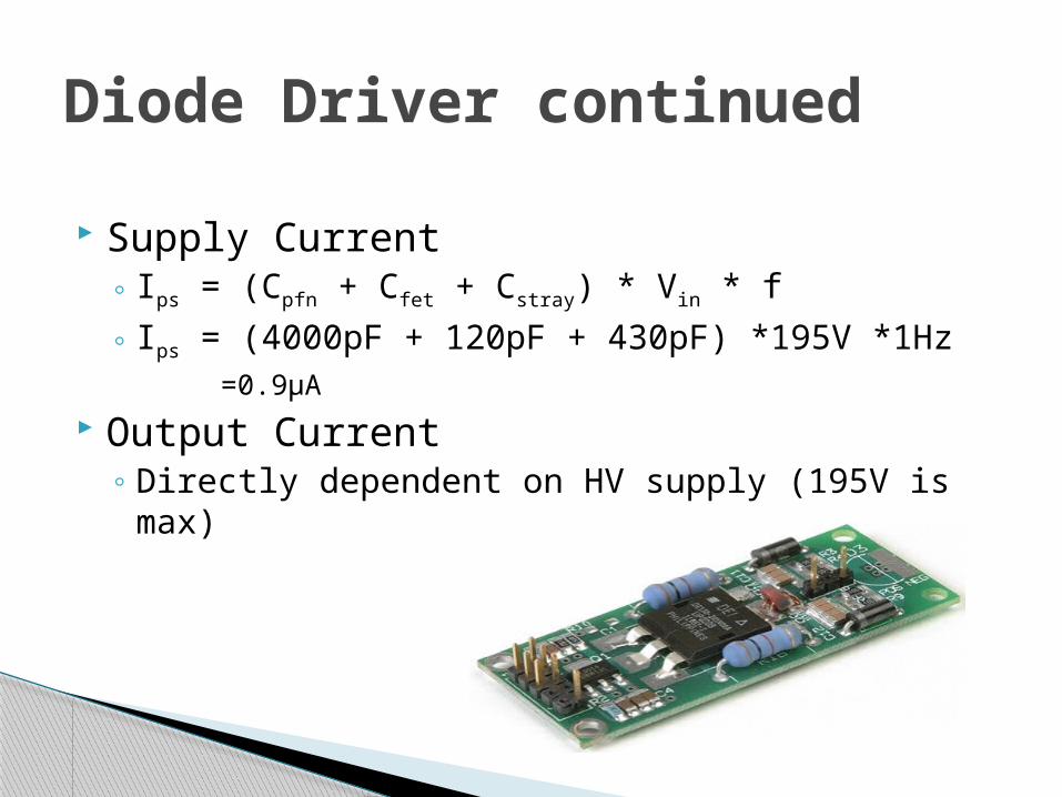
Supply Current◦ Ips = (Cpfn + Cfet + Cstray) * Vin * f◦ Ips = (4000pF + 120pF + 430pF) *195V *1Hz
=0.9µA Output Current
◦ Directly dependent on HV supply (195V is max)
Diode Driver continued

JP1 Connection
Diode Driver Continued
Pin 1 GroundPin 2 15V @ 1mA (support power)Pin 3 GroundPin 4 Gate (Trigger) 5VPin 5 Ground
Pin 10 HV in (0 - 195V @ Ips)
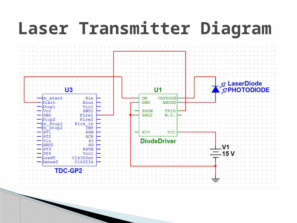
Laser Transmitter Diagram

Transmitter Prototype Overview
Transmitter Electronics
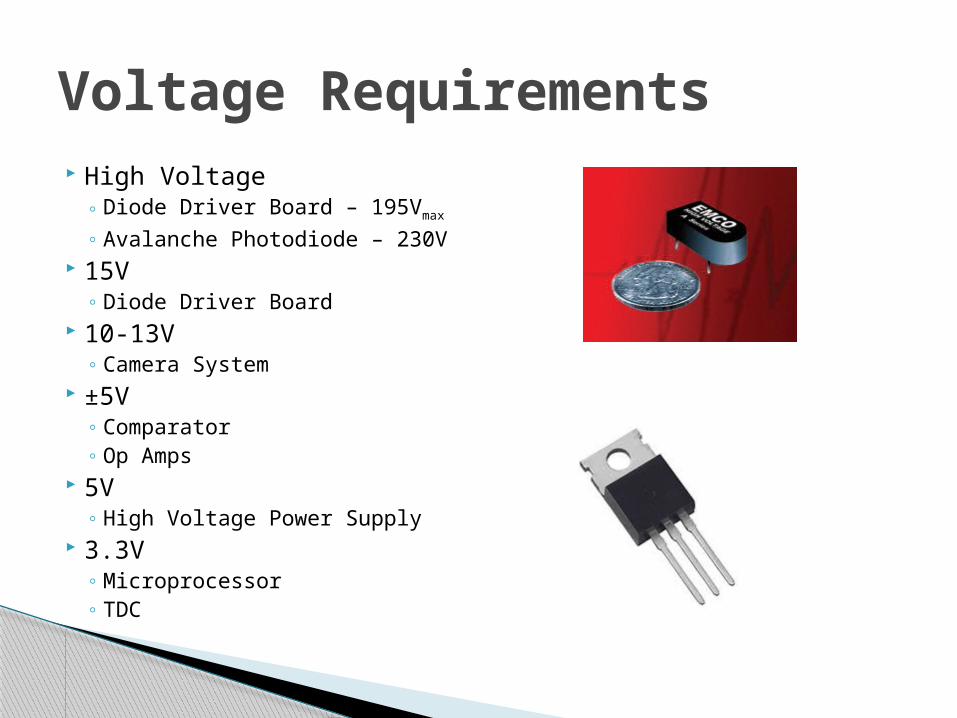
High Voltage◦ Diode Driver Board – 195Vmax◦ Avalanche Photodiode – 230V
15V◦ Diode Driver Board
10-13V◦ Camera System
±5V◦ Comparator◦ Op Amps
5V◦ High Voltage Power Supply
3.3V◦ Microprocessor◦ TDC
Voltage Requirements
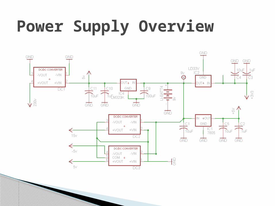
Power Supply Overview

PCB Overview Designed and
Build using ExpressPCB
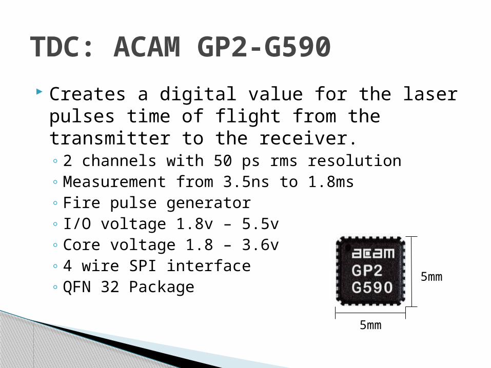
TDC: ACAM GP2-G590 Creates a digital value for the laser pulses
time of flight from the transmitter to the receiver.◦ 2 channels with 50 ps rms resolution◦ Measurement from 3.5ns to 1.8ms◦ Fire pulse generator◦ I/O voltage 1.8v – 5.5v◦ Core voltage 1.8 – 3.6v◦ 4 wire SPI interface◦ QFN 32 Package 5mm
5mm
Microcontroller◦ Programming Language: C◦ Development Environment: Arduino Uno IDE◦ Handles data collection and peripheral control
GUI◦ Programming Language: C#◦ Development Environment: MS Visual Studio◦ Receives user input and displays relevant
information
Software Design
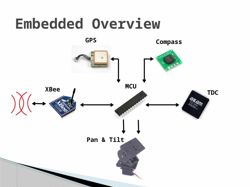
Embedded Overview
MCUXBee TDC
Pan & Tilt
GPS Compass
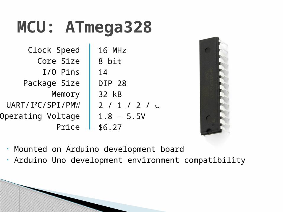
MCU: ATmega328Clock Speed
Core SizeI/O Pins
Package SizeMemory
UART/I2C/SPI/PMWOperating Voltage
Price
16 MHz8 bit14DIP 2832 kB2 / 1 / 2 / 61.8 – 5.5V$6.27
• Mounted on Arduino development board• Arduino Uno development environment compatibility
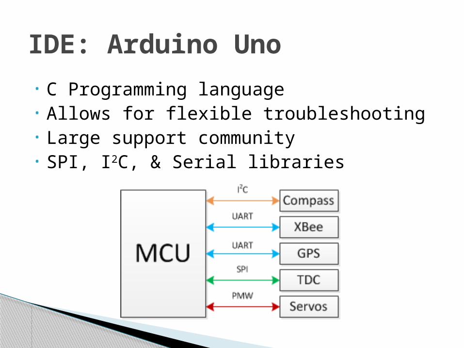
• C Programming language• Allows for flexible troubleshooting • Large support community• SPI, I2C, & Serial libraries
IDE: Arduino Uno
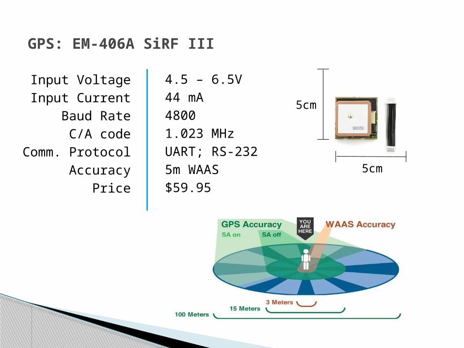
GPS: EM-406A SiRF III
Input VoltageInput Current
Baud RateC/A code
Comm. ProtocolAccuracy
Price
4.5 – 6.5V 44 mA48001.023 MHzUART; RS-2325m WAAS$59.95
5cm
5cm
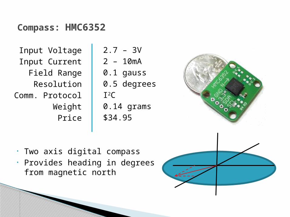
Compass: HMC6352
Input VoltageInput Current
Field RangeResolution
Comm. ProtocolWeight
Price
2.7 – 3V2 – 10mA0.1 gauss0.5 degreesI2C0.14 grams$34.95
• Two axis digital compass• Provides heading in degrees
from magnetic north

100ft radial distance Omni-directional link Low Power Consumption
Wireless Comm: Overview
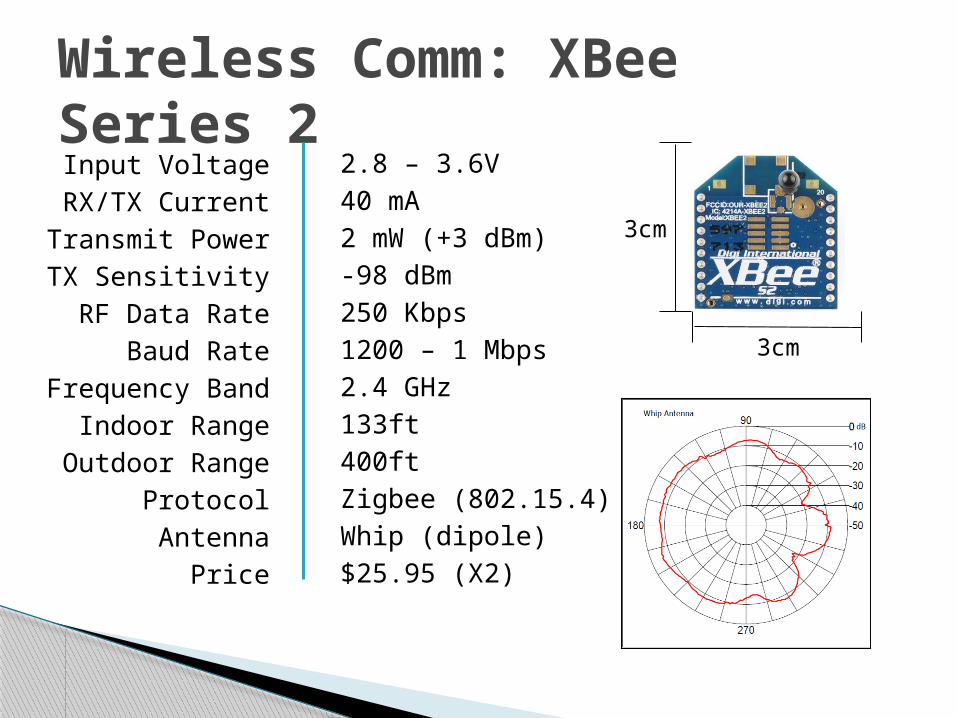
Wireless Comm: XBee Series 2
Input VoltageRX/TX Current
Transmit PowerTX SensitivityRF Data Rate
Baud RateFrequency Band
Indoor RangeOutdoor Range
ProtocolAntenna
Price
2.8 – 3.6V40 mA2 mW (+3 dBm)-98 dBm250 Kbps1200 – 1 Mbps2.4 GHz133ft400ftZigbee (802.15.4)Whip (dipole)$25.95 (X2)
3cm
3cm
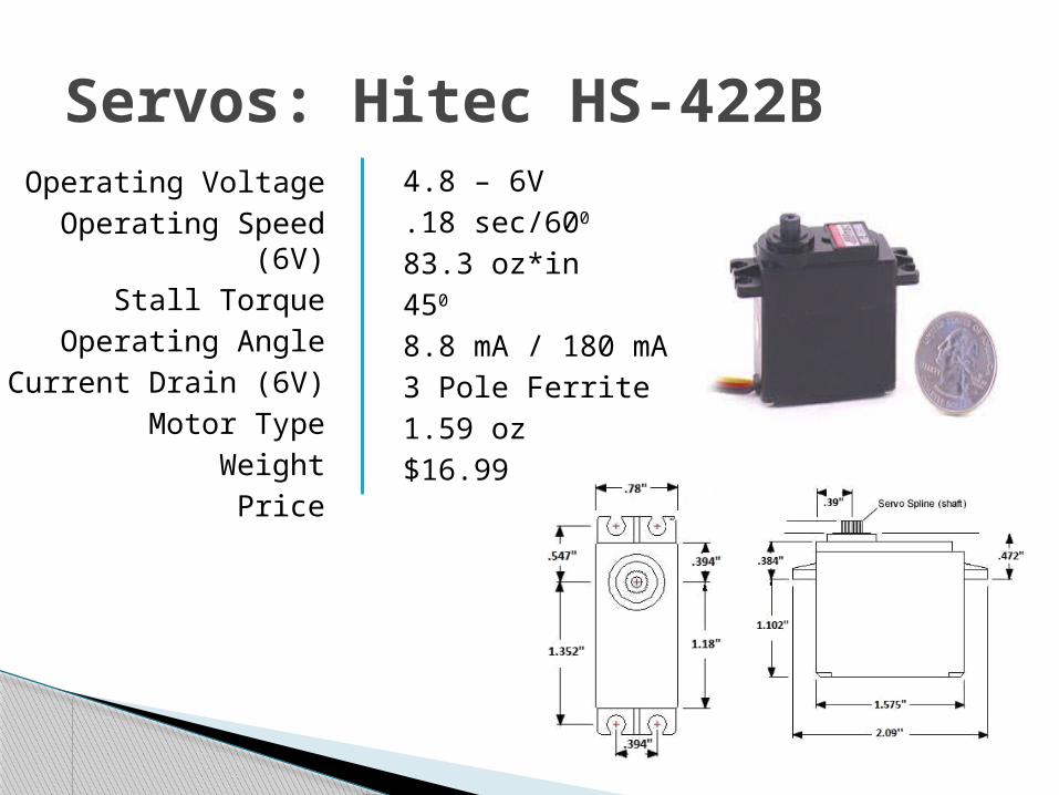
Servos: Hitec HS-422BOperating Voltage
Operating Speed (6V)Stall Torque
Operating AngleCurrent Drain (6V)
Motor TypeWeight
Price
4.8 – 6V.18 sec/600
83.3 oz*in450
8.8 mA / 180 mA3 Pole Ferrite1.59 oz$16.99
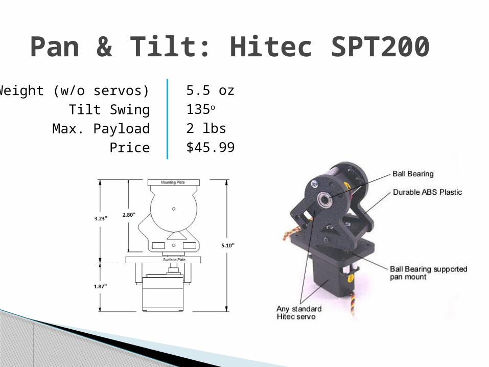
Pan & Tilt: Hitec SPT200Weight (w/o servos)
Tilt SwingMax. Payload
Price
5.5 oz135o
2 lbs$45.99
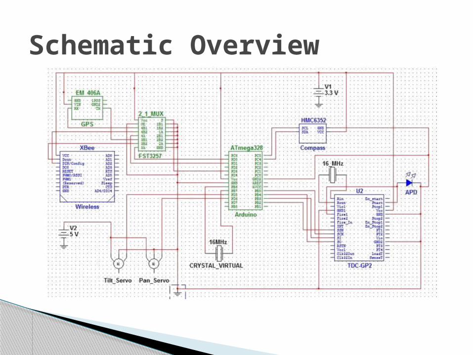
Schematic Overview
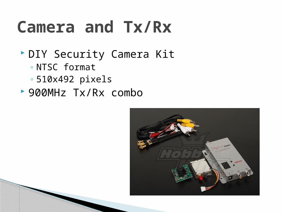
DIY Security Camera Kit◦ NTSC format◦ 510x492 pixels
900MHz Tx/Rx combo
Camera and Tx/Rx
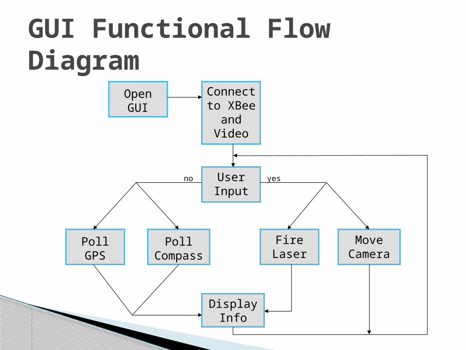
GUI Functional Flow Diagram
Open GUI
Connect to XBee
and Video
Poll GPS
Poll Compass
Display Info
User Input
Move Camera
Fire Laser
no yes
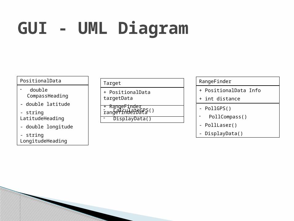
GUI - UML Diagram
PositionalData
- double CompassHeading
- double latitude
- string LatitudeHeading
- double longitude
- string LongitudeHeading
RangeFinder
+ PositionalData Info
+ int distance
- PollGPS()- PollCompass()
- PollLaser()
- DisplayData()
Target
+ PositionalData targetData
+ RangeFinder rangefinderData
- CalculateGPS()- DisplayData()
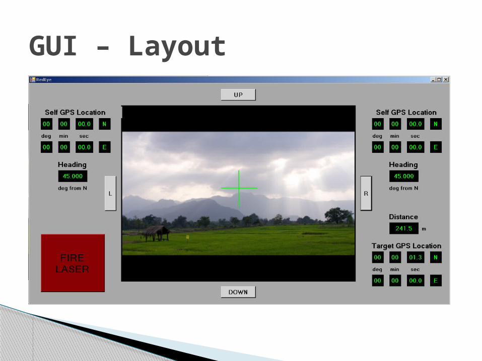
GUI – Layout

Given:◦ Self GPS Coordinates
Latitude (N/S ddmm.mmmm) Longitude (E/W ddmm.mmmm)
◦ Distance to target (m)◦ Heading clockwise from magnetic north (deg)
Calculate:◦ Target GPS Coordinates
Latitude (N/S ddmm.mmmm) Longitude (E/W ddmm.mmmm)
Target GPS Algorithm

Spherical Law of Cosines
◦ Self GPS coordinates (lat1, lon1)◦ Distance to target (d)◦ Heading (Θ)◦ Radius of the earth (R)◦ Target GPS coordinates (lat2, lon2)
[ ]lat2 = sin-1[ sin(lat1)*cos(d/R) + cos(lat1)*sin(d/R)*cos(Θ) ]
lon2 = lon1 + tan-12 cos(lat1)*sin(d/R)*sin(Θ) cos(d/R) - sin(lat1)*sin(lat2)
Target GPS Algorithm – cont.
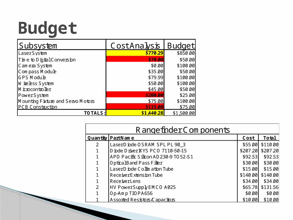
Budget
Quantity Part Name Cost Total2 Laser Diode OSRAM SPL PL 90_3 $55.00 $110.001 Diode Driver IXYS PCO 7110-50-15 $207.20 $207.201 APD Pacific Silicon AD230-9 TO52-S1 $92.53 $92.531 Optical Band Pass Filter $30.00 $30.001 Laser Diode Collimation Tube $15.00 $15.001 Receiver Extension Tube $140.00 $140.001 Receiver Lens $34.00 $34.002 HV Power Supply EMCO A025 $65.78 $131.561 Op-Amp TI OPA656 $0.00 $0.001 Assorted Resistors/Capacitors $10.00 $10.00
Rangefinder Components
Subsystem Cost Analysis BudgetLaser System $770.29 $850.00Time to Digital Conversion $70.00 $50.00Camera System $0.00 $100.00Compass Module $35.00 $50.00GPS Module $79.99 $100.00Wireless System $50.00 $100.00Microcontroller $45.00 $50.00Power System $200.00 $25.00Mounting Fixture and Servo Motors $75.00 $100.00PCB Construction $115.00 $75.00
TOTALS: $1,440.28 $1,500.00
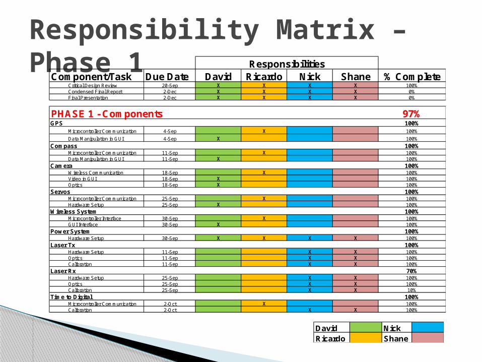
Responsibility Matrix – Phase 1
David NickRicardo Shane
Component/Task Due Date David Ricardo Nick Shane % CompleteCritical Design Review 20-Sep X X X X 100%Condensed Final Report 2-Dec X X X X 0%Final Presentation 2-Dec X X X X 0%
PHASE 1 - Components 97%GPS 100%
Microcontroller Communication 4-Sep X 100%Data Manipulation in GUI 4-Sep X 100%
Compass 100%Microcontroller Communication 11-Sep X 100%Data Manipulation in GUI 11-Sep X 100%
Camera 100%Wireless Communication 18-Sep X 100%Video in GUI 18-Sep X 100%Optics 18-Sep X 100%
Servos 100%Microcontroller Communication 25-Sep X 100%Hardware Setup 25-Sep X 100%
Wireless System 100%Microcontroller Interface 30-Sep X 100%GUI Interface 30-Sep X 100%
Power System 100%Hardware Setup 30-Sep X X X X 100%
Laser Tx 100%Hardware Setup 11-Sep X X 100%Optics 11-Sep X X 100%Calibration 11-Sep X X 100%
Laser Rx 70%Hardware Setup 25-Sep X X 100%Optics 25-Sep X X 100%Calibration 25-Sep X X 10%
Time to Digital 100%Microcontroller Communication 2-Oct X 100%Calibration 2-Oct X X 100%
Responsibilities
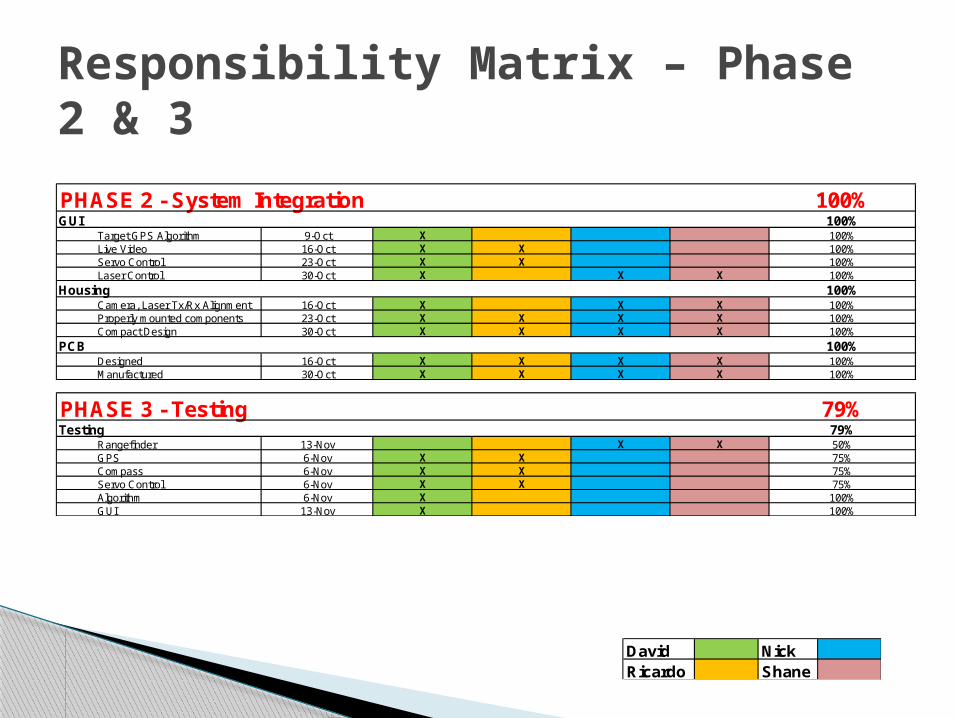
Responsibility Matrix – Phase 2 & 3
David NickRicardo Shane
PHASE 2 - System Integration 100%GUI 100%
Target GPS Algorithm 9-Oct X 100%Live Video 16-Oct X X 100%Servo Control 23-Oct X X 100%Laser Control 30-Oct X X X 100%
Housing 100%Camera, Laser Tx/Rx Alignment 16-Oct X X X 100%Properly mounted components 23-Oct X X X X 100%Compact Design 30-Oct X X X X 100%
PCB 100%Designed 16-Oct X X X X 100%Manufactured 30-Oct X X X X 100%
PHASE 3 - Testing 79%Testing 79%
Rangefinder 13-Nov X X 50%GPS 6-Nov X X 75%Compass 6-Nov X X 75%Servo Control 6-Nov X X 75%Algorithm 6-Nov X 100%GUI 13-Nov X 100%

Environmental conditions Laser transmitter and receiver alignment Divergence t0 Timing Cost
◦ Replacing broken parts Compass and GPS polling Noise
Problems Encountered

QUESTIONS?