Project RAVEN: Robotic Assist Vehicle for Extraterrestrial...
24
Avionics Kevin Davis (UMD) Jennifer Donaldson (UMD) Elaine Petro (UMD) Wayne Yu (UMD) Crew Systems Kevin Buckley (UMD) Albert Zhou (UMD) Systems Integration Zach Gonnsen (UMD) Brandon Litt (UMD) Laura Meyer (UMD) Lauren Puglisi (ASU) Power, Propulsion & Thermal Greg Holste (UMD) Marissa Intelisano (UMD) Christopher Mak (UMD) Loads, Structures & Mechanisms Jayne Breitwieser (UMD) James Dogget (UMD) Brandon Hall (UMD) Justin Hill (UMD) Mission Planning and Science Andrew Britton (ASU) Tut Gatyiel (ASU) Ricardo Gutierrez (ASU) Samantha Lustig (UMD) Leon Manifredi (ASU) Sean Marshall (ASU) Kyle Montgomery (ASU) Rodric Richenberg (ASU) Matthew Smith (ASU) Robert Wagner (ASU) Timothy White (ASU) Ji-hyoung Woo (ASU) University of Maryland Arizona State University Faculty Advisors Dr. David Akin Dr. Srikanth Saripalli Dr. Mary Bowden Project RAVEN: Robotic Assist Vehicle for Extraterrestrial Navigation
-
Upload
trinhquynh -
Category
Documents
-
view
216 -
download
1
Transcript of Project RAVEN: Robotic Assist Vehicle for Extraterrestrial...

Avionics Kevin Davis (UMD) Jennifer Donaldson (UMD) Elaine Petro (UMD) Wayne Yu (UMD)
Crew Systems Kevin Buckley (UMD) Albert Zhou (UMD)
Systems Integration Zach Gonnsen (UMD) Brandon Litt (UMD) Laura Meyer (UMD) Lauren Puglisi (ASU)
Power, Propulsion &
Thermal Greg Holste (UMD) Marissa Intelisano (UMD) Christopher Mak (UMD)
Loads, Structures &
Mechanisms Jayne Breitwieser (UMD) James Dogget (UMD) Brandon Hall (UMD) Justin Hill (UMD)
Mission Planning
and Science Andrew Britton (ASU) Tut Gatyiel (ASU) Ricardo Gutierrez (ASU) Samantha Lustig (UMD) Leon Manifredi (ASU) Sean Marshall (ASU) Kyle Montgomery (ASU) Rodric Richenberg (ASU) Matthew Smith (ASU) Robert Wagner (ASU) Timothy White (ASU) Ji-hyoung Woo (ASU)
University of Maryland Arizona State University
Faculty Advisors Dr. David Akin Dr. Srikanth Saripalli Dr. Mary Bowden
Project RAVEN: Robotic Assist Vehicle for Extraterrestrial Navigation

1
Introduction The goal of a lunar sortie mission is to land in a remote location away from permanent infrastructure and to
conduct as many scientific experiments as possible in a only few days of human presence. Astronauts already
have trouble walking in their space suits; in order to gather samples and conduct experiments astronauts must carry awkward hardware and sample bags. There is Apollo video footage of multiple astronauts dropping tools
and samples, then falling as they try to retrieve their equipment. It takes great effort for the astronaut to
resituate their center of mass over their feet in order to recover. In the process, they may contaminate their samples, or break valuable science hardware. This wastes astronaut strength and extravehicular activity (EVA) time.
During the first few Apollo missions, an average of 42kg of samples were collected per trip, and were
moved on foot by suited astronauts. The distance traveled was around 1km per EVA, and took almost 4 hours.
During Apollo 14 astronauts used the Modular Equipment Transporter (MET), a small cart designed to carry
their tools. The MET took 10 minutes to set up and was not capable of traveling through the EVA traverses. At one point Edgar Mitchell radioed, “Al's got the back of the MET now and we are carrying it up. I think it seems
easier." The 210kg LRV was deployed from a volume of nearly 8m3, and designed to carry astronauts rather
than provide logistic support during EVA. By using a lunar sortie model, similar to that of the Constellation program, it is our objective to provide
astronauts with a small, easy to assemble fully supportive assistance vehicle while on EVA. These support systems include: cargo and mission equipment transport and access, robotic mechanisms to assist with
science objectives, the ability to follow and keep up with a loping astronaut at speed without direct input, identify hazardous terrain to avoid obstacles, and to operate via teleoperation after the astronauts depart. RAVEN also has the ability to carry an astronaut in an emergency situation. Some of the project level one
requirements include: a stowed mass under 150kg, a stowed volume of less than 3m3, the ability to traverse
20° slopes, clear 30 cm obstacles, utilize a dexterous manipulator, recharge autonomously to support an 8
hour EVA, and keep pace with loping astronauts on the lunar surface while following them autonomously. Mission Profile
The duration of each EVA with the astronauts will be 6 to 8
hours. The science objectives of the sortie missions are to take
high resolution images of the lunar terrain, to collect lunar samples, and to search for signs of water-ice. As a reference
mission for RAVEN, the area around Shackleton crater will be
the main focus of exploration during the EVAs. The total distance that RAVEN and the astronauts will travel together during one EVA is between 1 and 2 km. A maximum speed of 3
m/s will be achieved during the EVA to enable the rover to travel at astronaut speeds. This report is based off of this reference
mission. Maintaining the ability to travel anywhere on the lunar surface, RAVEN was designed to also fit any Lunar Electric
Rover (LER) mission architecture, and provide well rounded support for a variety of mission types. It was
important to design RAVEN so it could be incorporated on existing lunar architecture to supplement existing
plans for a lunar exploration mission. A concept of the integration of RAVEN onto LER is shown in Figure 1. Project Structure
The two senior capstone classes from the University of Maryland’s Department of Aerospace Engineering
and the Arizona State University School of Earth and Space Exploration, designed RAVEN to meet level one
requirements established by their professors. An Earth and a lunar rover were designed concurrently as shown
in Figure 2. The goal was for the Earth rover to mimic the lunar rover’s capabilities and specifications in order to
test vehicle configurations and design features. Due to the concurrent design and time constraints, the two
vehicles diverged slightly as will be discussed later in this report. This paper will cover the lunar rover design
process, and then continue into the design and testing of the Earth analog.
Figure 1: LER integration

2
Technical Specifications Three wheels
Several trade studies were conducted to determine the optimal wheel configuration that would
minimize the vehicle’s overall mass while providing adequate stability. The conclusion of these trade studies
was that a three wheeled system offers a 10 percent mass reduction as compared to a four wheeled vehicle. Use of a passive swiveling rear wheel allowed a differential wheel drive for steering which further eliminated the mass of dedicated steering actuators. The front two wheels, which
are mounted on the same axis, act as the drive wheels; steering is achieved by varying the speed of each individual wheel
Table 1 shows the maximum lateral acceleration
the rover can withstand while turning, and the weight transfer from the front to back wheels during braking
experienced on different slopes. This analysis shows that adequate stability is achievable using a three-wheeled
vehicle while minimizing mass. Driving
For operations on the the lunar surface, a vehicle should have the capability to scale a 20o slope and a
30-cm obstacle. The vehicle’s tires were sized by ensuring the tire dimensions produced a net positive forward
force (drawbar pull). The wheel diameter was chosen to be 60cm in order to minimize mass while being able to
scale a 30cm obstacle with a passive suspension system. A terramechanics analysis produced an optimal drive wheel width of 10 cm and a caster wheel width of 5 cm. Grousers, protrusions from the tire that dig into
the regolith to increase tractive force, were also required in order to achieve positive drawbar pull up the
maximum slope. Twelve grousers with a height of 3mm were selected. The tire chosen for RAVEN was an
aluminum wire mesh tire, the same tire chosen for the LRV (TRL 9). When selecting and sizing the motors, two driving
scenarios were considered: a standard mission and a contingency
situation in which an astronaut would be carried. The astronaut-carrying contingency drove the motor requirements, with each
motor being capable of providing 55 N-m torque and 112 W.
Structure Loads Analysis
During the chassis optimization process, the beam elements on the left and right side of the vehicle were assumed to be symmetric. The selected cross sections are hollow square tubes with outer dimensions of 20, 30 and 40 mm and wall thicknesses of 1 and 2 mm. The primary requirement for the chassis is that it can withstand the forces experienced during operation and launch, while having a mass less than 12 kg. The material chosen for the lunar chassis is Al-2024-T81. A safety factor of 2 was chosen and the margin of safety minimized during the optimization process. All loading conditions in Table 2 were approximated using point forces, and the chassis is able to support expected loads with approximately 11 kg of structural mass.
Figure 2: [LEFT] RAVEN Model, [RIGHT] Earth Analog in Lunar Simulation
Table 1: Comparison of Three and Four Wheel Stability Parameters
Table 2 Loads Table

3
Suspension System
RAVEN’s suspension was designed to optimize the range of motion of the suspension, minimize force transmission, and to quickly damp oscillations. The suspension was approximated as a two-degree-of-freedom mass-spring-damper system. The worst-case loading scenario was found to be a 30-cm drop during the astronaut carrying contingency. Figure 3 plots the maximum displacement under this load for different spring and damping constants. Analysis of the graph, along with the forces acting on the suspension system led to the determination that the suspension should have a 35,000 N/m spring constant and a 2,500 N-s/m damping constant.
The two front wheels employ a Chapman strut design, which consists of a spring/damper and lower A-arm that are both mounted to the chassis. A traditional viscous damper was deemed unsuitable for the mission due to the range of temperature extremes that RAVEN will experience during its life on the moon. A magnetic damper (TRL 4) was chosen because magnets are able to maintain their magnetic properties over much wider temperature ranges.
The rear wheel system utilizes a trailing-arm suspension, which is modeled in Figure 4. The rear wheel is connected to the chassis at the chassis pin (blue piece in model) and it is allowed to rotate 360° at this position.
Avionics Navigation Overview
RAVEN is equipped with a sensor suite that allows it to track and follow an astronaut, autonomously avoid obstacles, and determine its
own position, velocity, and acceleration. The
configuration for the vehicle is shown in Figure 5.
The rover tracks the astronaut using a laser range
scanner and a radio direction finder. The radio
direction finder provides the bearing to the
astronaut of interest and the laser range scanner (beam shown in orange) provides the distance.
The rover is equipped with a second laser range
scanner (beam shown in red) dedicated to
obstacle detection. A set of stereo science and
navigation cameras are mounted to the front sensor arch and two hazard cameras are mounted to
each side to aid in obstacle detection. RAVEN is equipped with wheel encoders on each of the front driven
wheels and an IMU placed at the rover center of mass for dead reckoning navigation. Ranging from the Lunar Relay Satellites (if available) provide the absolute position of the rover on the lunar surface. Astronaut Following
Radio Direction Finder In order to follow the astronaut, the rover must know the distance to the astronaut and the astronaut’s
bearing. The laser scanner gives the distance to any object at a height above most obstacles (1.4 m) and that objects’ bearing. The radio direction finding (RDF) (TRL 6) system gives the bearing of a radio frequency (RF)
Figure 5: Navigation Sensor Overview
Figure 3: Displacement vs. Spring Constant
Figure 4: Rear Wheel Assembly

4
source on the astronaut’s suit, allowing the rover to differentiate
between an obstacle and an astronaut. Each astronaut will transmit at a
different frequency so if more than one is in the field, the astronauts can
select whom the rover follows. The RDF antenna consists of two sets of Adcock aerial pairs and
one omni-directional antenna to resolve a 180° ambiguity. The antenna
pattern is shown in Figure 6. The primary constraint on the design of the
antenna is the aerial spacing (aperture). In Adcock antennas, as the
spacing becomes wider, the lobes begin to lose their circularity which
causes bearing errors. On the other hand, if the spacing is too narrow, sensitivity is reduced. Therefore, the spacing was chosen to be no more than 1/3 wavelength and no less than
1/10 wavelength. For an operational frequency of 440 MHz, the antennas were designed with a 10 cm
aperture. Besides spacing, the main source of error is multipath and reflections of the signal, however, there are not
as many possible sources of interference on the Moon (no large buildings or terrain features) and since the
RDF system is being used to verify the direction information provided by the laser scanner (not triangulate), the
errors will not significantly affect the performance of the astronaut following system.
Laser Scanner There are two scanning laser range finders (TRL 8) on RAVEN which
provide two-dimensional range and bearing information to targets or obstacles. The distance to an object can be extracted from the light pulse
reflection time. A rotating mirror spreads the pulses out over a 180° arc and
gives the corresponding bearings. Laser scanners are ideal for a mobile
navigation platform like RAVEN because they are fast (30 Hz), precise and
have a relatively long range. They have a typical range of 30 meters with a
resolution of 1 cm or better. The detection capability of the laser scanner is
dependent on the reflectivity of the obstacle surface for the operational wavelength of laser light.
The first laser scanner is dedicated to astronaut tracking and is placed
on the front sensor arch at 1.4m above the ground, where it will clear most obstacles. The laser scanner is mounted so that the scanning plane is parallel to the ground. The second laser scanner dedicated to obstacle detection is angled down 12° from the horizontal. The configuration is shown in
Figure 7. The laser scanners also provide a “follow astronaut’s path” ability, where the navigation system record astronauts exact position over time to calculate a path versus calculating a direct path to the astronaut.
Obstacle Detection and Avoidance Second Laser Scanner Placement The rover is designed to clear obstacles 30 cm or smaller with a
worst case stopping distance of approximately 4 m. The placement of the
second laser scanner was chosen so that it can detect an obstacle larger than 30 cm at a distance of 5 m in front of the rover. The 5 m distance was chosen to incorporate a
minimum 1 m (0.33 second, ~10 laser scans) margin to give the system time to react. A diagram
of the detection scheme is shown below in Figure
8. The laser scanner was placed just below the
first laser scanner at a height of 1.4 m and tilted down 12° from the horizontal to give the shortest distance to
the ground and the largest effective field of view. RAVEN is limited to travel on a 20° slope, so it must be able to detect the grade of a slope that it is
approaching as shown in Figure 9. Since the tilt angle is 12° (the largest possible based on obstacle detection
requirements), the scanner needs to be articulated so that the angle can be adjusted when a down-slope of greater than 12° is encountered. Additionally, as the rover passes over bump as shown in Figure 9, the IMU will be used to correct for the tilt of the vehicle plane.
Figure 7: First Laser Scanner Placement
Figure 8: Second Laser Scanner Detection
Figure 9: Detection Scenarios
Figure 6: RDF Antenna Diagram

5
Stereo Camera System Stereo cameras will be used as part of the navigation system for medium to long range sensing. Since the
stereo camera system will have a slower response time than the laser scanners - 4 Hz versus 30 Hz - they will be used as a preliminary obstacle detection system only. While the laser scanner alone will provide enough
coverage for the rover to safely maneuver its maximum turn radius (3.7 m up slope, max speed), the hazard
cameras allow for a zero radius turn and aid in teleoperation. The rover will be equipped with high intensity
LEDs providing a 45˚ lighting field illuminating 30 m forward. They will be mounted with the cameras to provide
light for the regions in the field of view. For navigation purposes, the stereo cameras will detect objects at 30 m with a resolution of 10 cm and the
images will be down sampled to 256 x 256 pixels in order to speed up the processing algorithms. Even at this
reduced resolution, stereo image processing is computationally demanding and thus will be implemented on its
own FPGA (Field Programmable Gate Array) with an estimated update rate of approximately 4 Hz. Odometry System
A two-level odometry system will be implemented on RAVEN. The primary system is based on an IMU and
wheel encoders where the IMU gives rotational information and the encoders give 2D translational information.
This system is expected to maintain a 10% position error for nominal driving conditions. A secondary visual odometry system (using the stereo cameras) will be running in the background and a comparison between the
two systems will be used to detect wheel slippage. Once slip has been detected, the rover will favor the visual odometry system information until it resumes normal driving conditions. Computer System
RAVEN’s computer (TRL 7) is based on the SpaceCube developed by Goddard Space Flight Center. This
computer has two Xilinx Virtex 4 Field Programmable Gate Arrays each with two embedded PowerPC hard
cores. FPGA’s excel at signal processing and other math-intensive applications, so algorithms for laser scanning and stereo image processing will be implemented in the FPGA logic. In addition to the resources of the FPGA, RAVEN’s general purpose processors must provide an estimated 680 MIPS. The current flight tested SpaceCube provides 700 MIPS, which satisfies this requirement. The computer communicates with the
rest of the hardware on RAVEN via a Spacewire bus. Spacewire can handle a data rate of 200Mbps, which
meets RAVEN’s requirement for providing HD video. It also provides a standard mechanism for packets, simplifying interface definitions between components, and saving engineering cost and effort. Other advantages include low voltage data signaling, which leads to power consumption ½ to ⅓ that of legacy buses
such as RS-422 and MIL-STD-1553B.
Crew Systems Rover Controls During an EVA, the astronaut will constantly need to be fed information about suit health, mission
checklists, status of RAVEN, warnings, etc. A Head Mounted Display (HMD) (TRL 6) offers the astronaut the
ability to have a customizable display that can show them information they deem important to the task at hand
(Figure 10). By being worn on their head, the display follows their line of sight, not forcing them to look away
from the task being performed.
Photo courtesy of ILC Dover
Figure 10: HMD Testing on I-Suit and HMD Astronaut View Concept

6
As the primary means of interaction with the
rover, voice commands are top-level orders which
direct the rover’s functions other than driving.
These include a “kill” command to halt all driving
and robotic arm functionality, a lights on/off ability, and the astronaut following or “follow my path” commands. Besides providing functional commands to the rover itself, voice commands will control the display viewed by the astronaut on the
HMD by verbally navigating menus and selecting different options. To complement the HMD and voice commands, the astronaut will also have an array of buttons directly
integrated into their suit known as the Rover Wrist Controller (RWC) (TRL 6). It will serve as a functioning
system while providing redundancy for controlling the rover and consists of four command buttons (activate, lights, follow me, follow my path) and a covered kill switch. The layout is shown in Figure 11. The kill switch is a
mechanical switch while the other buttons are pressure sensitive and electrically conductive Electronic Textiles
(E-Textiles). In order to prevent accidental initiation of commands, the “activate” command is used in sequence
with the command desired. For example, to initiate astronaut following, the command would be as follows: Activate Follow Me Activate. The kill switch however, is designed for fast activation as a covered
mechanical switch with no need for the activate command. Remote Rover Controller (RRC) While in normal operation, the astronaut will have the ability to control the rover remotely using the
RRC.(TRL 6) It will be a joystick that can be mounted to the torso section of the astronaut suit with
accelerometers inside the mount that will detect irregular operation (e.g. the astronaut falling onto the
controller). The decision to make the RRC a joystick interface was based on the results of a self-designed experiment
testing three input interfaces – joystick, joypad, and head tracking – in combination with two types of displays –
monitor and HMD. Using the Terrabuilder Moon add-on for Microsoft Flight Simulator 2004, a simulated lunar environment course was created to navigate the rover through. The goal was to navigate the course in the
shortest time while avoiding all obstacles. Each test recorded the times it took to navigate through each gate, the number of crashes per run, and the
number of flips per successful run. After each timed trial, test subjects were asked to rate the controls using the
NASA Task Load Index (TLX), and the Cooper-Harper System. The Analytic Hierarchy Processes (AHP) pair-wise comparison was used in the post-test-questionnaire to compare each system to each other.
Analysis of the results indicated that a monitor joypad/joystick control scheme performs the best using the
rating and testing protocols mentioned. In order to more accurately simulate astronaut capabilities with
handling controllers, another round of experiments was conducted using a “glovebox” which is a depressurized
cylinder sealed at a 4.3 psi pressure differential. It has two ports for inserting shuttle suit arms to simulate a
pressurized suit. With the glovebox, the test subjects preferred the joystick over the joypad. Thus between the
results of the original and the glovebox experiments, the joystick was chosen as the most effective controller for rover driving purposes.
Astronaut Carrying Capability In the case of an emergency where an astronaut is incapacitated, RAVEN will have the ability to carry an
astronaut. The healthy astronaut will be able to secure the injured crew member to the rover and drive RAVEN
back to the lander remotely. To accommodate an
incapacitated astronaut, mass will need to be removed from the rover in order to maintain stability.
Removable mass such as the
science instruments and the
robotic arm will be discarded, removing 25kg of mass and leaving
only the components necessary to
drive RAVEN back to the lander. To
remove the robotic arm, there are quick releases that allow the arm to fall off when disengaged. Once the mass
is removed, the front arch on the rover will be folded down, and there will be a soft seat that will unfold and
Figure 12: Crew Accommodation
Figure 11: RWC Layout

7
stretch between the stanchions of the folded down front arch. As the laser scanners are mounted on the front arch, this configuration of RAVEN will not be able to use the astronaut following ability, so once the
incapacitated astronaut is seated and restrained, the healthy astronaut must remotely drive the rover back to
the lander. In order to restrain the astronaut in place, the injured astronaut’s Primary Life Support System
(PLSS) will use a latch system to connect and lock to the rear arch, which will hold the astronaut’s upper body
in place, along with supporting most of their weight as shown in Figure 12. The latches will be able to withstand
7400N of force, based on crash load requirements. If the seated astronaut needs to unlatch from the rover on
their own, there are quick releases easily accessible to release their PLSS from the rover. To keep the
astronaut’s lower body in place, an adjustable belt strap will be used to restrain the waist. The astronaut is
placed such that their center of mass is situated over the center of mass of the rover, minimizing the
destabilizing effects of adding the mass of the astronaut. However since adding the mass of the astronaut raises the center of mass of the rover by 0.8m, the stability is affected such that RAVEN must operate at a
reduced speed of 1.5m/s. Communications
The rover communications platform serves two main purposes: transmitting science data collected during
the mission and aiding in teleoperation of the rover. Additionally, the rover can serve as a voice and data
relay platform for the astronauts while on EVA. The
rover is equipped with three antennas: a high gain
Ka-band antenna (TRL 9) for data transmission to
Earth, an S-band hemispherical antennas for local lunar surface communications and for contact with
the Lunar Relay Satellites (LRS), and an omni-directional UHF antenna for receiving astronaut voice
commands and voice relay. An overall diagram of the
system is displayed in Figure 13. S-band hemispherical antennas transmit at 2.29
GHz with a 4 dBi gain and a 135° half-power beam
width. While on EVA, the astronauts’ suits transmit images from their helmet cameras to the rover along with
suit telemetry. If the LRS are available, the S-band antennas may also be used to get ranging information for absolute position determination and to relay data through the LRS back to Earth. In addition to the S-band data
relay, an Ultra High Frequency (UHF) omni-directional antenna transmitting at 279 MHz is used for voice
command and voice relay. For direct to Earth communications, a Ka-band parabolic dish antenna transmitting at 32 GHz is mounted
on a motorized pan and tilt mechanism so that it can be pointed at Earth when the rover is stationary to transmit high resolution images, video, and science data. At 8 watts power, the system has a 150 Mbps data rate, which
means up to 67.5 GB/hr data transfer is possible. Using MPEG-2 High 1440 level video compression HD video
(1440 x 1080 px) can be encoded and transmitted at 60 Mbps for a total of two possible channels of streaming
HD video. If the parabolic dish fails, direct to Earth (DTE) communications will not be lost. If the LRS are in orbit, the S-band antenna can transmit data to the LRS, relaying it back to Earth. If the LRS are not available, high
power, a low bandwidth DTE link can be established.
Science Experiments The science experiments include: a camera experiment that will survey the landscape and take panoramic
views, a microscopic imager connected to a robotic dexterous manipulator that will take images of rock
samples, a seismometer experiment that will be performed to locate the presence of water-ice, and a
magnetometer experiment that will measure the magnetic anomalies on the lunar surface in order to map a
magnetic field near the lunar South Pole. The dexterous manipulator will be attached to the front of RAVEN and
will be used to help support the science objectives. It is important to note that the design of the dexterous
manipulator was not part of the design task for RAVEN. The dexterous manipulator is Government Furnished
Equipment (GFE) and will integrate with the systems on RAVEN. It will fulfill tasks that astronauts are not capable to do themselves due to the restrictions from their astronaut suits. The dexterous manipulator will be
controlled by the astronauts from RAVEN and also teleoperated by ground control and the astronauts at the
lunar lander. The robotic arm will serve interchangeably for the use of the microscopic imager and as a tool to
place seismic units on the lunar surface when used on EVAs with the astronauts. Before the lunar lander departs the Moon’s surface, a series of configuration changes will be performed.
The dexterous manipulator will be teleoperated once the astronauts leave the Moon and it will only support the
Figure 13: Communications Overview

8
microscopic imager. Solar panels will be mounted onto the lunar rover in order to obtain power. Once the
astronauts depart the Moon, RAVEN will be teleoperated from the ground station on Earth. The scientific
missions that RAVEN will perform after the astronauts depart include: imaging the lunar surface, collecting
magnetometer data, and utilizing the microscopic imager attached to the dexterous manipulator. Camera Experiment
Stereo cameras (TRL 9) were chosen to help indentify geologic structures and rock compositions of the lunar regolith. These cameras will act as navigation and extra-vehicular activity performance tools.
Separated with a baseline of 10cm the cameras have the ability to identify an object 10cm in diameter from a
distance of 3m. A near infrared mapping spectrometer will be used for indentifying a mineral resource known as
water-ice. Water-ice can be identified at the near infrared wavelengths using the characteristic peak at 1.8um
surrounded by a trough at 1.5 and 2.0 micrometers. The spectrometer will be based on a larger version of the
NIMS that flew on the Galileo spacecraft. A Lunar Hand Lens Imager (LuHLI) (TRL 6) will capture images of samples of interest to identify fine
scale minerals. The ability to look at minerals up close can tell a scientist the environment in which they were
formed as well as which minerals formed first. LuHLI will have white LEDs to illuminate the sample of interest to
allow for imaging in poor lighting conditions. LuHLI can be attached to the dexterous manipulator for teleoperated control. Seismometer Experiment
ASGARD seismometers (TRL 5) will first be calibrated using lunar simulant, lunar simulant on top of ice
sheets, and lunar simulant mixed with water-ice to determine the seismic velocities we would expect to find if water is present in the lunar subsurface. Once these velocities are determined, different materials will be tested
for their seismic velocities to see if their seismic velocities can be distinguished from that of water. Examples
include CO2 ice and other volatiles, metal alloys, basalt, and K-poor plagioclase. Once these seismic velocities
have been determined, lunar experimentation can be successfully conducted. The Apollo experiments were conducted in the low- to mid-latitudes of the Moon. By conducting a similar
experiment at a pole, it will be possible to determine if the subsurface of the Moon is homogenous at all latitudes and if water-ice may be present. The active seismic experiments conducted by the Apollo astronauts
created their own seismic events by using a thumper, which set off explosive charges. Water is known to have
a strong effect on seismic velocities on Earth. Seismic velocities of regolith range from 92 to 114 m/s, while
Earth sediments have measured about 1650 m/s unfrozen and over 2400 m/s frozen. Regolith seismic
velocities may be different when ice is present, so Earth-based experiments will be conducted to determine
which seismic velocities our seismometer should look for. Most lunar rocks are basalts, so crushed basaltic
rock will be placed in a basin, and a weight will be dropped onto the basalts. The seismic velocity will be
recorded by the seismometer, and this will be done with and without frozen water. Magnetometer Experiment
The objective of the magnetometer sensor package for lunar exploration is to measure magnetic fields on
the surface of the Moon in order to understand the thermal history of the lunar crust, and to determine the
evolution of a theorized core/dynamo. The magnetometer will also study the physics of basin forming impacts
on surface magnetization. Determining the remnant crustal magnetic field is important in piecing together the
Moon’s magnetic history. The magnetic history of the Moon is largely unknown at present, but the data
obtained from high resolution mapping of lunar surface samples will help us begin answering questions about the evolution of the Moon’s interior and surface.
The magnetometer is a combination of three separate tri-axial magnetometers. Two magnetometers will be mounted to the rover. In order to measure all aspects of the local magnetic field, one magnetometer will be
situated near the base of the rover close to the ground in order to measure the regolith magnetic influence. The
second magnetometer will be mounted high up on the rover to measure the ambient magnetic field of the area.
The third magnetometer will be portable sitting atop a tripod and will be used to measure specific areas of interest determined by vehicle traverses. Mapping traverses will be made by traveling in a grid pattern. Data
will be logged continuously at a sample rate of 10 Hz and downloaded at the end of each traverse for analysis.
The fluxgate sensors used in this system will have a range of ±400 nT and resolution of 0.1 nT. Anomalies will be detected and recorded both by the rover magnetometers and the portable magnetometer. Power
The critical power requirement is the ability to support an eight hour EVA. This naturally translates into the
required ability to also maintain power throughout the remainder of a lunar day, as well as the extended lunar night. The rover is intended to operate until failure and as such its power source needs to be rechargeable.
Table 3 divides the rover operations into six separate modes of power consumption. This is broken down into
9
less ambiguous power usage groups. The constraining energy requirements are the 8 hour EVA and the
approximately 15 day lunar night. The computed values for these situations are shown in Table 4 along with the
total energy that would be used in the course of a typical lunar day. The lunar night has the larger requirement because even though the night power mode only consumes a
small amount of power, the
rover does not have the
opportunity to recharge like it does during the lunar day after an EVA.
Lithium ion batteries were
chosen as the battery type
because they have no charge
memory, a high energy density, and a high open circuit voltage.
The Saft VES 180 (TRL 6) was chosen as the battery because even though it has a smaller volumetric energy
density than some of the other options, it was superior in its nominal capacity (50 Ah), weight (1.11kg), and
gravimetric energy density (175Wh/kg). Arranging three strings in parallel of eight cells of VES 180 batteries in
series provides a total 4662 Wh of energy. This arrangement will weigh 27kg, will occupy a volume of 0.03 m3,
and will also provide approximately 225 Ah at 24 volts. In order to maintain teleoperation after the astronauts depart from the
lunar surface, the rover will need a power source to recharge its batteries.
Without a base
station to recharge
from or an onboard
energy source, the implementation of a solar panel is the
most viable choice because solar energy is abundant and directly accessible.
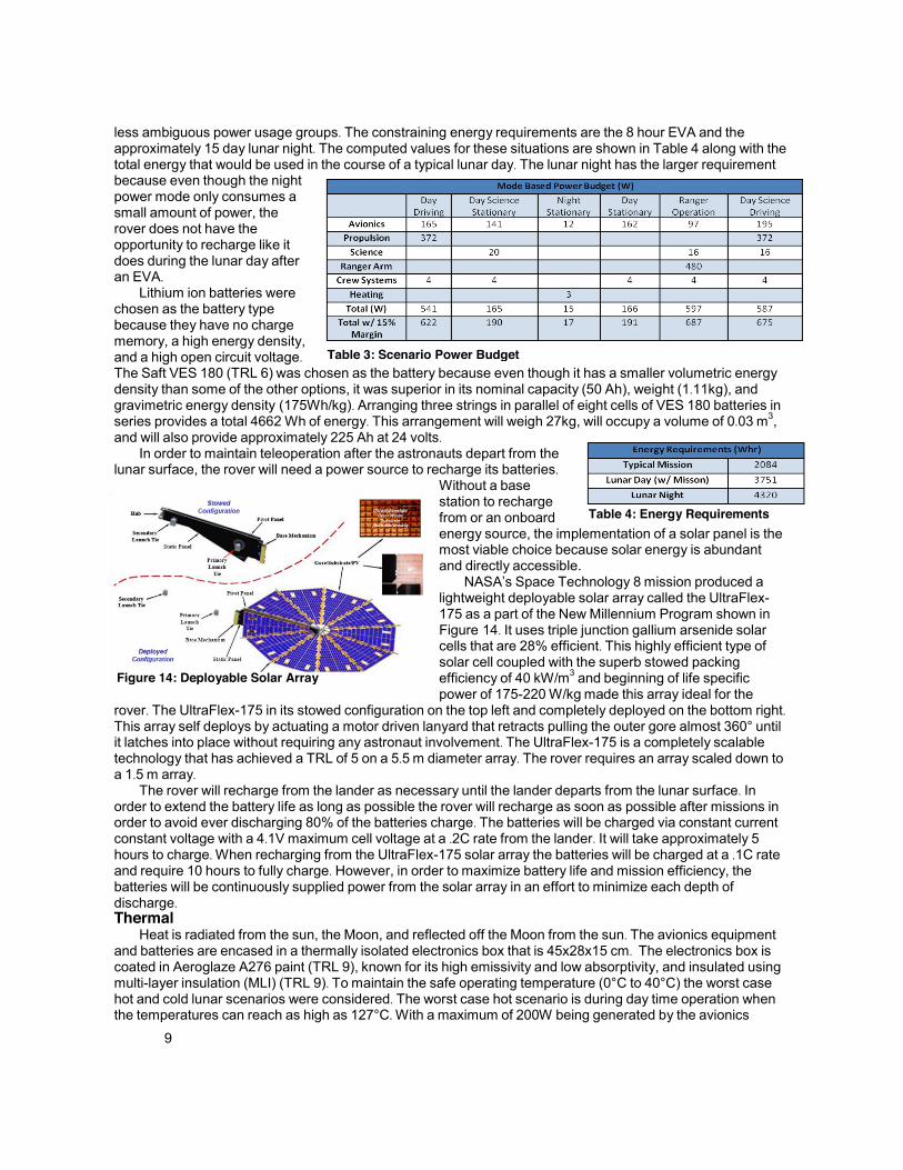
NASA’s Space Technology 8 mission produced a
lightweight deployable solar array called the UltraFlex-175 as a part of the New Millennium Program shown in
Figure 14. It uses triple junction gallium arsenide solar cells that are 28% efficient. This highly efficient type of solar cell coupled with the superb stowed packing
efficiency of 40 kW/m3 and beginning of life specific
power of 175-220 W/kg made this array ideal for the
rover. The UltraFlex-175 in its stowed configuration on the top left and completely deployed on the bottom right. This array self deploys by actuating a motor driven lanyard that retracts pulling the outer gore almost 360° until it latches into place without requiring any astronaut involvement. The UltraFlex-175 is a completely scalable
technology that has achieved a TRL of 5 on a 5.5 m diameter array. The rover requires an array scaled down to
a 1.5 m array. The rover will recharge from the lander as necessary until the lander departs from the lunar surface. In
order to extend the battery life as long as possible the rover will recharge as soon as possible after missions in
order to avoid ever discharging 80% of the batteries charge. The batteries will be charged via constant current constant voltage with a 4.1V maximum cell voltage at a .2C rate from the lander. It will take approximately 5
hours to charge. When recharging from the UltraFlex-175 solar array the batteries will be charged at a .1C rate
and require 10 hours to fully charge. However, in order to maximize battery life and mission efficiency, the
batteries will be continuously supplied power from the solar array in an effort to minimize each depth of discharge. Thermal
Heat is radiated from the sun, the Moon, and reflected off the Moon from the sun. The avionics equipment and batteries are encased in a thermally isolated electronics box that is 45x28x15 cm. The electronics box is
coated in Aeroglaze A276 paint (TRL 9), known for its high emissivity and low absorptivity, and insulated using
multi-layer insulation (MLI) (TRL 9). To maintain the safe operating temperature (0°C to 40°C) the worst case
hot and cold lunar scenarios were considered. The worst case hot scenario is during day time operation when
the temperatures can reach as high as 127°C. With a maximum of 200W being generated by the avionics
Table 3: Scenario Power Budget
Figure 14: Deployable Solar Array
Table 4: Energy Requirements

10
equipment and batteries, a radiator will be necessary to dissipate the additional heat. By considering flexible
Silvered Teflon optical solar reflectors and aluminum radiator coated in Aeroglaze A276, the Silvered Teflon
optical solar reflectors (TRL 9) result in a smaller radiator of 0.4 m2 because they reflect solar radiation more
efficiently. A solar louver will be placed on top of the radiator to regulate the heat flow. A louver is a thermal shutter that opens up when the internal temperature is too high and close when the temperature is too low. It will require no power and when closed will protect the radiator from regolith.
The worst case cold scenario is during the 15 day nights when temperatures are as low as -169°C and only
the processors are running and the antenna is transmitting. To survive the quantity of MLI is important. An
emissivity (ability to emit energy by radiation) of 0.11 or lower is needed to maintain the lower limit of the safe
operating temperature. This can be achieved with 5 layers of MLI or more. Additionally, Kapton heaters will provide heat if necessary.
Systems Analysis Feasibility
In order to get a complete picture of the strength of the design for RAVEN, a failure mode and effects
analysis (FMEA) was completed to get an idea of the weak points in the design. In order to use a FMEA several factors needed to be categorized for every failure that can occur. First the potential effect of the failure
determines its severity. The higher the severity of the failure the higher rating it received. After determining
each failures effect on the system, the different causes were rated on how often they may occur. The
occurrence rating then corresponded to each potential cause of a failure. Finally, looking at the different ways
to detect and prevent each failure a ranking was given to the causes based off the likelihood of detection. With
numbers quantifying the severity, occurrence and ability of detection for each cause of a failure they were
ranked by a risk priority number (RPN). This number gives an early approximation of which systems have the
greatest risk and thus what further design decisions should be made in order to increase the reliability of the
system. A chart displaying our top causes of mission
failure and their risk priority numbers are shown in
Figure 15. This chart displays that further design
considerations must be made on the pivot point for the
third wheel and on the axle stresses in order to lower the overall risk of our system. This analysis has shown
where weak points are in the design and thus where
future design efforts need to be emphasized. Costing Analysis
Two common NASA cost estimators are the
Spacecraft/Vehicle Level Cost estimator and the
Advanced Mission Cost model. The
Spacecraft/Vehicle level Cost estimator is solely based
on mass to cost exponential relations. Since RAVEN is a
design in between a
manned spacecraft and a
scientific instrument, both
of those mass
relationships were
considered. Assuming
RAVEN weighs 149 kg
(rover mass plus robotic
arm mass), then the
estimator predicts RAVEN
to cost around $360
million in developmental costs and about $20
million for the first unit production cost if the
rover is considered a
manned spacecraft or about $28 million in
developmental costs and
Table 5: Goddard Cost Estimator Part Prices
Figure 15: Risk Review

11
$11 million for first unit production costs if the vehicle is considered a scientific instrument. As a general note, all cost analysis numbers mentioned in this paper are in 2010 dollars and are inflated to 2010 dollars from their original prediction using the NASA New Start Index Inflation Calculator.
The range of values above are too broad even for initial cost estimation so an additional cost model was
used, the Advanced Mission Cost Model. The Advanced Mission Cost Model bases its cost estimates on of the
quantity needed, dry weight, mission type, year of the initial operating capability, the block number, and the
difficulty level of programmatic and technical features of the design. The block number represents the number of design iterations thus far. For all new designs, the block number is one, modifications to an existing design is
a block number of two. This cost model is useful because it considers more factors than just mass and has a
more compatible mission type option, lunar rover, but it only produces a predicted total cost for the vehicle
instead of splitting developmental and production costs. This makes it difficult to determine the reasonability of the results. If the system is given the inputs of lunar rover, operating capability by 2020, and high difficulty, then
it produces a total cost for producing one vehicle at $223 million. This total value falls almost exactly in between
the Spacecraft/Vehicle Level Cost estimator predictions for the manned spacecraft and scientific instrument and thus appears to be of a reasonable order of magnitude.
Since the Advanced Mission Cost Model only gives a total cost, it is useful to break up the cost a little
further with other models. Models from the "Space Systems Quick Estimating Guide" made by NASA Goddard
Office of the Comptroller were used to predict component costs for RAVEN. All of the part cost estimates use
an exponential mass predictor like the Spacecraft/Vehicle Level Cost Estimator except that the variables are
customized for each vehicle component. The guide did not include mass/cost predictors for laser scanners, thumper, and IMU and thus they used the relationships for the closest related item. A summary of the cost results are shown in Table 5. The total cost in Table 5 is only $16 million of the predicted $223 million. The
remaining cost stem from systems design work, integration and test, launch vehicle, mission operations, and
other overhead costs. Thus we predict the total cost is $223 million.
Earth Analog Design and Testing Overview
An Earth analog version of RAVEN was designed, built and tested in order gauge the effectiveness of the vehicle as an astronaut-assisting rover. The vehicle was constructed primarily out of 80/20™ T-slot extrusions and other commercial-off-the-shelf components. The following sections detail design specifications and decisions. Software
Software's role in the Earth analog is to support and lead operations of the rover throughout its mission
profile. The rover must operate at the astronaut loping speed (1 m/s), so the control scheme had to be able to
operate at that speed. The rover must also have the ability to be controlled by someone who is not physically
with the rover. Finally, control of the robotic arm also needs to be supported. The arm and its computer were
provided by the Space Systems Lab to be integrated onto our analog vehicle. One onboard computer runs the main rover control software, a second computer controls the robotic arm,
while a third computer is provided for data collection for the science experiments. They communicate via a
wireless local area connection provided by the onboard router. Any number of outside computers can connect to the network to command the rover and request data.
The software is divided into two sections, the client software and the main software. The main software
runs on the main rover computer itself, while the client software works on separate client computers. The
software has been designed and also implemented in a current Earth analog rover. The software on the rover and the software on the computer communicate using UDP data packets. The Arduino microcontroller on
board speaks with the main rover computer through data placed in the serial buffer to read. Feedback is then
given from the Arduino to the main computer on the motor outputs. To control the rover, a joystick connected to
the client computer provides driving inputs. The rover is driven using a standard gamepad controller, where the right and left joysticks control the
individual motor speeds. Testing has been done to ensure safety and for joystick calibration. Software also
provides protection from either network connection failures, or joystick input failures. Both pieces of software
have failsafe measures that shut down the power relays that run the rover if a failure occurs. Continued testing will be done with sensors to sense obstacles and provide autonomy to the software and
in the control scheme of the rover. A basic path planning algorithm will be further implemented to demonstrate
lunar rover astronaut following. Also, a separate client computer is installed control to the robotic arm.

12
C&DH Electronics The main computer was selected to be a Mobile Computing Solution Mini-ITX Carputer. It features a 1.6
GHz dual core Atom processor, 1 GB RAM, and a 32 GB solid state hard drive. A solid state hard drive was
selected due to the shocks expected from driving over rough terrain. Mechanical hard drives are prone to
damage and failure in high vibrational environments. The robotic arm’s is a similar model, and the science
computer is a Mac Mini. The main computer alone does not have the necessary interfaces to communicate with and control some
of the analog’s avionics hardware. These interfaces include an I2C databus and analog to digital conversion for some of our sensors, as well as general pin input-output to control power distribution, and pulse width
modulation (PWM) to control the motor controllers. These interfaces are provided by an Arduino Duemilanove
development board. Figure 16 shows the data interfaces for
each of the sensors and other hardware. The
main computer communicates with Arduino
via USB. Each of the computers is connected
to the router via wired Ethernet, and can be
accessed individually over the wireless
network. For example, commands for arm
motion would be sent to the robotic arm
computer, commands to drive would be sent to
the main computer, and a command to
conduct an experiment or transmit science
data would be sent to the science computer. Commands to move the rover are sent to
the main computer and forwarded to the
Arduino, which then generates a PWM signal to control the motor controllers. The motor
controllers are IFI Victor 883’s, and are capable of providing 60 amps at 24 volts to the motors. The main
computer also has the ability to turn selected components of the rover off and on, using a set of relays toggled
by the Arduino. The robotic arm’s computer, motor controllers and actuators, as well as the main drive motors
for the rover, are all powered by a relay, and can be toggled off and on with software. The relay board provides
6 relay channels, and each channel is toggled with a GPIO line from the Arduino. A kill switch was implemented by placing a push-button locking switch in series with the power to the relay
driver board. Cutting power to this board results in loss of power to the relays’ coils. The relays are normally-open, so when power is cut, the contacts open and power is cut off. Since all of the actuators rely on power passing through relays, all powered movement of the rover and arm is stopped. Driving
For the Earth analog rover, a dry sand terrain model was chosen as a conservative terramechanics
analysis. A 60-cm pneumatic ATV tire was used for all three wheels and a terramechanics analysis carried out to determine the motor torques necessary for operation. The drive motor for each wheel was found to require
350 N-m of torque and 140 Watts of power. The motor selected was a high-torque motor with a 24:1 gear ratio
that came standard as part of the motor system. This step-up in torque was not quite enough however, so an
additional 3.75:1 gear ratio was necessary. The purpose of the drive system is to transfer torque to the rover’s two powered wheels, while preventing
loads from being carried directly by the electric motors. To
accomplish this, a wheel hub was manufactured that attached the
wheel’s 110 mm 4 bolt pattern to a 1-in diameter, keyed driveshaft. The driveshaft was supported by two flange-mounted ball bearing
units produced by SKF USA Inc. The flange-mounted bearings were
attached to the 80/20 chassis using ¼-in aluminum plates. All radial loads from the tire are transmitted though the bearings, and plates
into the chassis. The flange-mounted bearings allow the shaft and
wheel to rotate. In order to drive the system, a 5.92-in diameter, keyed roller sprocket is attached to a 2.09-in diameter sprocket on
the shaft of the electric drive motors using an ANSI #50H roller chain rated for a maximum load of 1400 lbs. The 2.8:1 gear ratio
Figure 16: Communications Overview
Figure 17: Drive System Diagram

13
(adequate for current testing) can be increased 3.75:1 by replacing the sprocket mounted to the driveshaft. The rear caster wheel was designed similarly to the drive wheels. A 1-in diameter axle was secured to a
custom-manufactured wheel hub and allowed to spin freely on two SKF USA Inc. flange-mounted bearings.
The additional caster degree-of-freedom was provided by mounting a steel turntable between the main rover chassis and the rear wheel assembly. The turntable allowed the caster wheel to rotate passively.
The loading analysis was a critical aspect in the design of the Earth analog version of the rover because
the need for a suspension was brought into question due to the expense and complexity of its implementation. A loads analysis was performed and indicated that the rover could withstand the loads without the aid of a
suspension. Loading was analyzed for collisions at the rover’s maximum speed of 1 m/s and for a drop from a
30 cm obstacle. Initial testing was performed on the Earth analog rover to determine vehicle performance on various
terrains. An average top speed of 1.1 m/s was recorded on both pavement and grass-covered areas. Slopes of over 30
o were also successfully climbed.
Science Camera Experiment
Two 1.3MP color CCD Point Grey cameras were selected for the Stereo/Navigation experiment. Attached
to an adjustable baseline and pan/tilt mechanism the cameras are able to perform 360° panoramas with
varying +/- 70° dip angle. All images are processed with a MATLAB calibration tool to reduce warping from
lens. Using a photo-stitcher called Hugin and a point cloud maker such as Microsoft Photosynth, a multitude of photometric analyses can be executed.
A 1.3MP monochrome CCD Point Grey camera was selected to act as an infrared camera. Attached to an
Orion filterwheel, the camera will image behind a 1.5, 1.8 and 2.0 µm filter to allow for water detection. The
infrared camera is placed at a similar viewing point as the stereo cameras for image referencing. A color CMOS Dino-Lite microscopic camera will operate as our hand lens imager. Attached to the
manipulator arm with a camera retraction mechanism, the camera will image fine-scale minerals. The resulting
image will be referenced with images captured by the stereo cameras. An interpretation of rock composition
will be made from stereo camera observations and then compared to the observations and interpretations
made from the following microscopic image capture. All subsystems of this camera experiment are operated
through a wireless controlled Mac Mini as a science computer powered by a Carnetix power regulator. Seismic Experiment
The seismometer consists of a geophone, accelerometer, data logger, XBee radio transmitter and
receiver, and Arduino microcontroller. The specifications require four identical seismometers whose data must be collected, stored, and sent wirelessly to the rover’s onboard computer at a minimum distance of 0.805 km.
The seismometer must have a minimum battery life of six hours in the field and store 30 minutes worth of data
onboard. The seismometer must also be held within a casing, with a large spike connected directly to the
geophone. The geophone’s range is from 10 to 240 Hz, and it has a three-axis accelerometer as a backup
seismic wave detector that detects orientation to determine that the seismometer is level. The uLog data
logger can hold one hour of seismic data. The XBee radio can transmit the data a mile, start and stop data
collection remotely, and enable wireless reprogramming. The electrical components run off 9-volt batteries, and the schematic was designed using Eagle CAD software.
The communication for the seismic experiment is based on DigiKey Xbee Pro radios, organized in a star network with a radio attached to the science computer at the center. The science computer will be able to
contact all nodes at once, while each node will contact only the science computer. Like the lunar design, the Earth analog seismic experiment software has two main sections: the data
recording and transmission software, which runs on the Arduino microcontroller in each node, and the
coordinator software, which runs on the science computer in the rover. The only significant difference between
seismic experiments for the Lunar and Earth analog designs is that the Earth analog does not have live
transmission of experiment data, due to hardware and programming time constraints. The software on the node waits for the rover to send a global "start" signal, which will allow all nodes to
start logging data simultaneously. Once started, each node logs data from all sensors to the uLog at 100 Hz.
They continue logging data until the rover sends a global "stop" signal, at which point they wait for individual commands to send data back to the rover. The science computer software is a Python script that will be run by
mission control. It sends a signal for all nodes to start recording, and then waits for mission control to tell it when the experiment has ended. Once this occurs, it sends the global "stop" signal, and starts querying each
individual node for its data. As data comes in, it is saved to text files on the rover.

14
Magnetometer Experiment An initial prototype has been constructed in order to test the implementation of the magnetometer. The
design and specifications for the magnetometer were modified to function in Earth’s much stronger magnetic
field. The signal processing unit for the Earth analog system is the Simple Aurora Monitor (SAM) kit which is
capable of measuring the output of two single axis magnetometer sensors and consists of an LCD screen and
attached keyboard with four buttons used for basic commands. The two sensors, which can measure a range
of ±50,000 nT with resolution of 1.2 nT and have a sample rate of 10 Hz, are mounted at the end of two
separate PVC pipes which are connected orthogonally to one another using a simple T-connector. A small circuit board is mounted inside the T-connecter providing a connection to both sensors and the output cable to
the SAM kit. The SAM kit is located on the rover near the Mac Mini computer, connected to it via serial (RS-232) to USB. The Mac Mini is responsible for running all data logging software during testing. A GPS unit logs
position coordinates during testing which are correlated with magnetic readings. Data logging is performed by
software supplied with the SAM kit. Once a traverse has been completed, data from the magnetometer as well as position data from the GPS unit is imported into MATLAB and analyzed to create magnetic intensity maps.
Some initial testing of the prototype system has been performed with moderate success. Three separate
experiments have been completed to verify that all components of the system are functional. The first experiment was conducted in order to verify the sensors were working correctly. This was achieved by placing
several small samples of various minerals next to the PVC mount for a period of 30 seconds and then removed.
As expected, the only mineral to register a change in the magnetic field was magnetite, thus the experiment was determined to be successful. The second experiment tested the affect of a running motor near the
sensors. A running drill was placed next to the sensors and once data was logged with the drill running, a
sample of magnetite was placed next to the drill. Both the drill and magnetite were then pulled away
simultaneously. The running drill was placed next to the sensors after 60 seconds. At 120 seconds the
magnetite was placed next to the drill and at 160 seconds both the drill and magnetite were pulled away. This
experiment was also determined to be successful as expected spikes were observed for both the drill and
magnetite sample. For the third test, a mock traverse of the Student Recreational Complex field at Arizona
State University was performed. All systems were placed on a mobile cart and pushed around the field in a grid
pattern. This experiment was also successful considering the GPS and magnetometer system logged data
successfully for the entire traverse.
Sensors Similar to the lunar design, the Earth analog vehicle will be equipped with two laser range scanners. They
are the Hokuyo UTM-30LX and the Hokuyo URG-04LX-UG01, which have 30 m and 5.6 m ranges
respectively. Both laser scanners transmit data over USB to the main computer. The laser scanners will be
used in obstacle detection during semi-autonomous operation. They will be placed in a similar configuration as
on the lunar vehicle, with the 30 m laser scanner scanning parallel to the ground and the 5.6 m angled down
towards the ground. The pointing angle of the second laser scanner will be optimized through testing based on
the response time of the electronics and the stopping distance for the Earth rover. Initial testing with the URG-04LX showed obstacle detection resolution of approximately 50 cm. Higher data sampling rates – not currently
implemented on the rover computer – are expected to reduce the minimum detectible obstacle size. The Earth analog vehicle is also equipped with four webcams which can stream real-time video. One on
the front, two on the sides (to simulate the hazard cameras), and a fourth mounted on the rear so the caster wheel behavior can be observed. These cameras will be used to simulate both EVA supervision and rover teleoperation from a ground control center and are currently being used as an aid to the driver in the open-loop
control of the vehicle. To determine its position, the analog vehicle uses a Garmin GPS 18x model GPS unit. This is analogous to
the lunar relay satellite ranging for the lunar design. The GPS data is paired with heading information from an
HMC6352 compass module to allow the rover to determine the heading and distance required to move to
another GPS point. A scheme is currently in development to follow a moving target, such as an astronaut in a
mock EVA. GPS data will be transmitted from another GPS unit on the astronaut’s suit and the rover will continuously determine the direction it must travel to follow the astronaut.
Odometry information will be provided by Hall Effect sensors mounted in the wheel box assemblies. The
hall sensors will be mounted next to the magnets on the motor sprocket, and each time a magnet passes, a
pulse will be generated. From this, the rotation rate of the wheel can be calculated, and therefore the rover speed can be determined. The analog vehicle will also be equipped with an accelerometer to determine its
orientation.

15
Future Work After the Augustine Commission submitted their report on the future of NASA in 2009, President Obama
and NASA Administrator Charlie Bolden steered NASA’s focus away from traveling to the Moon and towards
technology research and development with the goal of first landing on asteroids and landing on Mars by the
mid-2030s. RAVEN as described above was designed under the Constellation program but its functionality
would be helpful in any environment where an astronaut is collecting samples and conducting science. Thus
the current lunar design could be modified for any asteroids NASA chooses to explore and eventually for Mars exploration.
No matter what environment the final vehicle is designed for, it would be beneficial to undergo more
intensive human factors testing. One of the most difficult factors to design for is the human/robot interaction.
Students tried to take this into consideration with part placement but did not have a Constellation spacesuit to
properly test how the astronauts would interact with the rover. It would be beneficial to test the rovers with an
actual astronaut in the appropriate space suit under simulated lunar conditions. One great environment to test RAVEN in would be at NASA’s Desert RATS.
Outreach During this semester both the University of Maryland and Arizona State University participated in a variety
of outreach events. Together they accumulated over 560 outreach hours. The University of Maryland students
reached out to K-12 students by judging two science fairs, helping at an aerospace nonprofit’s table at Rockville Science day, and running the morning activity for the Girl Scout Engineering Saturday program at the
University of Maryland. The Maryland students also reached out to the general public by helping at two
Maryland open houses where they assisted approximately a combined 1000 students. Along with providing assistance, presentations about aerospace engineering were given to almost 100 students. Students also
attended a Women in Engineering prospective students tea party, helped at a physics tutoring clinic, called
prospective high school engineering students to discuss their experiences, and volunteered at a Saturday
engineering program for high school seniors. The Maryland students also hosted a demonstration of their Earth
analog rover for faculty, staff, students, and representatives from the local technical community. The largest event the Maryland students participated in was Maryland Day. Students demonstrated the rover, discussed
space exploration with visitors to the Space Systems Lab’s Moon Yard, gave tours of a mock-up lunar habitat, and volunteered at a booth for the engineering honors society. Arizona State University has also been very
active with outreach. They have provided outreach to the general public through hosting science activity tables
at ASU's homecoming event in the fall. Earth and Space Exploration Day, hosted by ASU’s School of Earth
and Space Exploration, was also a large event where the general public ranging in age from five to seventy-five participated in hands on activities and educational lectures. A large amount of the outreach hours on ASU's
side came from the ASU/NASA Space Grant Consortium. Outreach hours through this program were gained
by helping in the Mars Student Imaging Project (MSIP). For MSIP, students from all over the nation travel to
ASU's campus to generate a science question and use the Thermal Emission Imaging System (THEMIS) camera on board the Mars 2001 Odyssey spacecraft; currently in orbit around Mars. ASU students helped this
program by educating students in image analysis activities and providing scientific feedback on their presentations. From the multiple outreach activities it is clear that outreach is both fun and extremely important to further the interest and desire to continue space exploration and research.
Conclusions A lunar rover is important for improving an astronaut’s ability to conduct science missions effectively and
efficiently, while retaining the ability to conduct additional science missions without astronauts present. RAVEN is the ideal rover for a sortie-class mission because it has the ability to carry experiments, samples, and tools, thus improving the mission quality while minimizing required mass.

A. 1
Appendix 1. Building
Figure 18: We Used 80/20® Extruded Aluminum as
the Primary Construction Material
Figure 19: Finishing the Chassis Supports for
Rear Wheel and Arches
Figure 20: Mounting the Turntable for the Rear
Wheel
Figure 21: Making the front wheelboxes
Figure 22: Installing the Bearings, Axel and
Sprocket
Figure 23: Mounting the Wheel Hubs to Hold the
Front Wheels in Place
Figure 24: Motor Assembly, also Shown is the
Ranger Arm Mounting Plate
Figure 25: Arches mounted in Upright
Configuration
Figure 26: Electronics Box with Relays and Power
Converters
Figure 27: RAVEN with Robotic Arm

A. 2
Appendix 2. Science Equipment
Figure 28: Speaker and FGM-3 Sensor for
Magnetometer
Figure 29: Encased Simple Aurora Monitor Kit
Figure 30: Magnetometer PVC Mount with Sensors
Figure 31: Magnetite Next to Sensors
Figure 32: Magnetometer Mineral Experiment Data Set
Figure 33: Seismometer Etched Printed Circuit Board
Figure 34: Near-Complete Seismometer
Figure 35: Camera, Filter, Pan Tilt Setup

A. 1
Appendix 3. RAVEN in Action
Figure 36: Field Demonstration with a Simulated Astronaut
Figure 37: Field Demonstration at Maryland Day
Figure 38: RAVEN Driving Over a Mound
Figure 39: RAVEN Climbing a Curb
Figure 40: RAVEN Climbing Stairs

A. 2
Appendix 4. Outreach
Figure 41: Anne Arundel Fair
Figure 42: Spring Hill Elementary
Figure 43: Student and Children Building a Spacecraft
Figure 44: Students Explaining Rover to Maryland
Day Guests
Figure 45: Student Discussing a Poster on RAVEN's
Design
Figure 46: Arizona Earth and Space Exploration Day
Figure 47: Arizona Teacher Conference
Figure 48: Maryland Students Provided Tours Inside
this Lunar Habitat

A. 2
References
3D MiniLIDAR. http://www.honeybeerobotics.com/product‐examples/sensors
“A 3‐D Miniature LIDAR System for Mobile Robot Navigation,” NASA SBIR 2007 Solicitation.
http://sbir.nasa.gov/SBIR/abstracts/07/sbir/phase2/SBIR‐07‐2‐X7.03‐8844.html
“Advanced Mission Cost Model”. NASA Johnson Space Center. http://cost.jsc.nasa.gov/AMCM.html
“Aeroglaze A276 Reflective Polurethance” 1 Mar. 2010 <
http://www.lordfulfillment.com/upload/DS3010.pdf>.
Akin, Dave. ENAE484 2010 Class Notes. “Cost Estimation”.
http://spacecraft.ssl.umd.edu/academics/483F09/483F09L09.cost_est/483F09L09.html
Andrew G. Santo, Et al. The MESSENGER mission to Mercury: spacecraft and mission design, Planetary and
Space Science, Volume 49, Issues 14‐15, December 2001, Pages 1481‐1500.
“Apollo 14 Active Seismic Experiment." Lunar and Planetary Institute (LPI). Web. 19 May 2010.
<http://www.lpi.usra.edu/lunar/missions/apollo/apollo_14/experiments/as/index.shtml>.
Apollo 14 Passive Seismic Experiment." Lunar and Planetary Institute (LPI). Web. 19 May 2010.
<http://www.lpi.usra.edu/lunar/missions/apollo/apollo_14/experiments/pse/>.
Apollo 17 Experiments ‐ Lunar Atmospheric Composition." Lunar and Planetary Institute (LPI). Web. 19
May 2010. <http://www.lpi.usra.edu/lunar/missions/apollo/apollo_17/experiments/lace/>.
Basics Of TheWatson‐Watt Radio Direction Finding Technique” RDF Products. Original Writing: December,
1998. Accessed Feb. 12, 2010. http://www.rdfproducts.com/wn002_apl_01.pdf.
Baumgartner, E. T., Aghazarian, H., & Trebi‐Ollennu, A. (2001). "Rover localization results for the FIDO”
Cheng, Yang, Mark Maimone, and Larry Matthies. (2005). "Visual Odometry on the Mars Exploration
Rovers." Thesis. Jet Propulsion Laboratory, California Institute of Technology, 2005. IEEE Systems, Man and
Cybernetics Conference, 2005.
Cole, D. and Newman, P. “Using laser range data for 3D SLAM in outdoor environments. “In Proceedings of
International Conference on Robotics and Automation, Florida, 2006.
D. Schulz, W. Burgard, and D. Fox, “People tracking with mobile robots using sample‐based joint
probabilistic data association filters”. International Journal of Robotics Research, vol. 22, no. 2, 2003.
David G. MacDonnell, "Communications Analysis of Potential Upgrades of NASA's Deep Space Network"
M.S. Thesis, Department of Aerospace Engineering, University of Maryland, April, 2000
David, Leonard, “Planetary Lunar South Pole Landing Sites Studied,” Space.com, 4 June 2003, accessed: 2
March 2010, <http://www.space.com/missionlaunches/
E. Krotkov, et al., Field trials of a prototype Lunar rover under multi‐sensor safe‐guarded teleoperation
control, Proceedings of the American Nuclear Society 7th Topical Meeting Robotics Remote Systems, Augusta,
1997, vol. 1, pp. 575‐582.

A. 2
Fuller, Lunar Magnetism, Reviews of Geophysics, vol. 12, pp. 23‐70
Gernhardt, Mike. Integrating Life Sciences, Engineering & Operations Research to Optimize Human Safety
and Performance in Planetary Exploration. National Aeronautics and Space Administration, 20 Aug. 2009. Web.
Gockley, R., Forlizzi, J., and Simmons, R. 2007. Natural person‐following behavior for social robots. in HRI
'07. 2007, Arlington, Virginia, USA, ACM Press.
Golombek, M.P. The Mars Pathfinder Mission. Journal of Geophysical Research, vol. 102, no. E2, pp. 3953‐
65. 1997. http://www.agu.org/journals/je/v102/iE02/96JE02805/
Graziosi, David, and Ryan Lee. I‐Suit Advanced Spacesuit Design Improvements and Performance Testing.
Tech. no. 2003‐01‐2443. ILC Dover, 2003. Web. <http://spacecraft.ssl.umd.edu/design_lib/ICES03‐2443.I‐
Suit_tests.pdf>.
H. Surmann, A. Nuchter, and J. Hertzberg, “An autonomous mobile robot with a 3D laser range finder for 3D
exploration and digitalization of indoor environments,” Robotics and Autonomous Systems, vol. 45, pp. 181–
198, 2003.
H.G. Hopkins and F. Horner: "Direction‐Finding Site Errors at Very high Frequencies," Journal I.E.E. 1949,
Vol. 96 Part III, p. 321.
Halekas et al., Mapping of crustal magnetic anomalies on the lunar near side by the Lunar Prospector
electron reflectom, Journal of Geophysical Research‐Planets, vol. 106, issue: E11,pp. 27841‐27852.
Helmick, D., Cheng, Y., Clouse, D. and Matthies, L. (2004). “Path following using visual odometry for a Mars
rover in high‐slip environments,” IEEE Aerospace Conference, March 2004.
Hood et al., Formation of magnetic‐anomalies antipodal to lunar impact basins – 2‐dimensional model
calculations, Journal of Geophysical Research‐Solid Earth and Planets, vol. 96, issue: B6,pp. 9837‐9846.
Hood et al., Initial mapping and interpretation of lunar crustal magnetic anomalies using Lunar Prospector
magnetometer data, Journal of Geophysical Research‐Planets, vol. 106, issue: E11,pp. 27825‐27839.
In Proc. SPIE Conf. Sensor Fusion and Decentralized Control in Autonomous Robotic Systems IV, vol. 4571,
N, MA, Oct 2001.
J.D. Weinberg , R. Craig, P. Earhart, I. Gravseth, K.L. Miller, “FLASH LIDAR SYSTEMS FOR HAZARD
DETECTION, SURFACE NAVIGATION AND AUTONOMOUS RENDEZVOUS AND DOCKING.” Ball Aerospace. LEAG
Workshop on Enabling Exploration, 2007.
Klar, R. et al. “DESIGN CONSIDERATIONS FOR ADAPTING LEGACY SYSTEM ARCHITECTURES TO SPACEWIRE”
Kul B. Bhasin, Et al. “Lunar Communication Terminals for NASA Exploration Missions: Needs, Operations
Concepts and Architectures.” June 2008 – 26th AIAA ICSSC Conference – San Diego, California.
L. Matthies, M. Maimone, A. Johnson, Y. Cheng, R. Willson, C. Villalpando, S. Goldberg, A. Huertas, A. Stein,
and A. Angelova, “Computer vision on mars,” International Journal of Computer Vision, 2007.
Lin et al., Lunar‐surface magnetic field concentrations antipodal to young large impact basins, Icarus, vol.
74, pp. 529‐541.
Lindström, M. and Eklundh, J.‐O. 2001. Detecting and tracking moving objects from a mobile platform

A. 3
using a laser range scanner. In Proc. IEEE/RSJ Int. Conf. on Intelligent Robots and Systems (IROS).
Lutz, Charles C., Harley L. Stutesman, Maurice A. Carson, and James W. McBarron II. Apollo Experience
Report ‐ Development of the Extravehicular Mobility Unit. Tech. no. NASA TN D‐8093. Washington D.C.:
National Aeronautics and Space Administration, 1975. Web.
<http://history.nasa.gov/alsj/tnD8093EMUDevelop.pdf>.
Man‐Systems Integration Standards. Publication no. NASA/SP‐2010‐3407. National Aeronautics and Space
Administration. Web. <http://msis.jsc.nasa.gov/sections/section03.htm>.
Mathies, et al. 2006. “Computer Vision on Mars” Jet Propulsion Laboratory, California Institute of
Technology
Moon Composition and Resources." Web. 19 May 2010.
<http://www.neiu.edu/~jmhemzac/Mooncomp.htm>.
“Moon Facts Sheet.” NASA. 8 Mar. 2010 < http://nssdc.gsfc.nasa.gov/planetary/factsheet/Moonfact.html>.
NASA ‐ Web Standards ‐ 2cc." NASA ‐ Web Standards ‐ 3c. Web. 19 May 2010.
<http://standards.nasa.gov/documents/ksc>.
“NASA New Start Index Inflation Calculator”. NASA Johnson Space Center.
<http://cost.jsc.nasa.gov/inflation/nasa/inflateNASA.html>
Nistér, D., Naroditsky, O., & Bergen, J. (2005) “Visual Odometry for Ground Vehicle Applications,” Sarnoff
Corporation. CN5300, Princeton NJ 08530, USA.
“Optical Solar Reflector” 1 Mar. 2010
<http://www.qioptiqspace.com/Data/Documents/Optical%20Solar%20Reflectors.pdf>.
Prado, Mark. "PERMANENT ‐ Lunar Materials ‐ Origins/Composition." PERMANENT: Asteroid Mining,
Space Colonies, Commercialization. Web. 19 May 2010. <http://www.permanent.com/l‐compos.htm>.
Ramachandran, Kumar. “Gashydrate”. Geophysical Imaging –The Eyes of an Explorationist.
<http://kumar.prithivi.net/gashydrate.htm> 12 April, 2010
Rankin, A., Huertas, A., & Matthies, L. (2005). “Evaluation of stereo vision obstacle detection algorithms for
off‐road autonomous navigation,” AUVSI Symposium on Unmanned Systems, 2005.
Recommendation for Space Data Systems Standards, Proximity‐1 Space Link Protocol‐Physical Layer,
CCSDS 211.1‐B‐1, Consultative Committee for Space Data Sytems, Matera, Italy, April 2003
Resistance in Sodium Chloride Environments (MSFC‐STD‐3029). Materials and Processes Laboratory,
Metals Engineering Branch. Web.
S. Badal, R. Draper, and A. Hanson, “A practical obstacle detection and avoidance system,” in IEEE
Workshop Appl. Comput. Vis., Saratoga, FL, 1994, pp. 97–104.
“Solar Reflector” 17 Mar. 2010 <
http://www.konicaminolta.com/about/research/solar/img/index_pict004.jpg>.
Space Systems Quick Estimating Guide" NASA Goddard Office of the Comptroller, Version 1.0, 1991

A. 4
Technical Description, SICK Promiximity Laser Scanner, Industrial Safety Systems, Germany, July 7, 2004,
p.67.
The Development of Wheels for the Lunar Roving Vehicle,” NASA/TM—2009‐215798
Thermal Control Louvers” 8 Mar. 2010
<http://www.orbital.com/NewsInfo/Publications/TSD/Thermal_Louvers_Brochure.pdf>.
United States. NASA. Guidelines for the Selection of Metallic Materials for Stress Corrosion Cracking
United States. NASA. NASA Technical Standards. Fracture Control Requirements for Spaceflight Hardware.
NASA Standards. Web. 19 May 2010. <http://standards.nasa.gov/documents/nasa>.
United States. NASA. NASA Technical Standards. NASA Fastener Procurement, Receiving, Inspection, and
Storage Practices for Spaceflight Hardware. NASA Standards. Web. 19 May 2010.
<http://standards.nasa.gov/documents/nasa>.
Vatistas Haruyama, J., Ohtake, M., and Matsunaga, T., et al., “Lack of Exposed Ice Inside Lunar South Pole
Shackleton Crater,” Science, Vol. 322, No. 5903, Nov. 2008, pp. 938‐939.
Watkins, Joel S. et al. “Seismic investigation of the lunar regolith”. Proceedings of the Fourth Lunar Science
Conference (Supplement 4, Geochimica et Cosmochimica Acta) Vol. 3. Pages 2561‐2574 <
http://articles.adsabs.harvard.edu//full/1973LPSC....4.2561W/0002561.000.html> 19 May, 2010
Welch, B. W., & Connolly, J. W. (2006). “Autonomous Navigation Error Propagation Assessment for Lunar
Surface Mobility Applications” (National Air and Space Administration, Glenn Research Center). Cleveland, OH.
What Is Mars Made Of?" Universe Today. Web. 19 May 2010. <http://www.universetoday.com/guide‐to‐
space/mars/what‐is‐mars‐made‐of/>.
Zou, Y. L., Liu, J. Z., Liu, J. J.,&Xu, T., “Reflectance Spectral Characteristics of Lunar Surface Materials,”
Chinese J. Astron. Astrophys., 2004.