Project Proposal And Feasibility Study - Calvin College Kroon is a Senior Mechanical Engineering...
24
Project Proposal And Feasibility Study Calvin College Engineering Department Engineering 339 December 8, 2006 Advisor: Professor Nielson
Transcript of Project Proposal And Feasibility Study - Calvin College Kroon is a Senior Mechanical Engineering...

Project Proposal
And
Feasibility Study
Calvin College Engineering Department
Engineering 339
December 8, 2006
Advisor: Professor Nielson

Riding In Style ii
Abstract
The goal of this project is to experience the engineering design process by taking an idea from
concept to prototype. Our Team, “Riding In Style”, chose to design a four person human powered vehicle with a drive train that would maximize the efficiency of the vehicle. After researching current models on the market, we saw an opportunity to improve on existing drive train configurations. The proposed solution for the drive train is to have four independent drive systems that power a common rear axle. Each rider will have individual control of a gear set, which will allow them to pedal at their own pace.
In addition to designing a drive train configuration, our team needed to design a vehicle structure. The frame will support 4 adult persons plus some light gear. We selected a box style frame that will be made out of aluminum. The box frame will allow us to mount components easily in the appropriate places and the aluminum was selected because it is easy to work with and is light weight. After analyzing the time, components, and material needed to build this concept, we have determined the project to be feasible. By using the resources at Calvin along with commercial suppliers, the project will be able to be completed by April 2007.

� � � � � � � � � � � iii
Table of Contents
1. Introduction
1.1. Team Description…………………….…………………………………………….1 1.2. Project Background………………………………………………………………...1 1.3. Project Description…………………………………………………………………1
2. Christian Perspectives……………………………………………………..………………...2
3. Project Feasibility Analysis………………………………………………………………….3
3.1. Market Research…………………………………………………………………..3 3.2. Drive train…………………………………………………………………………3 3.3. Vehicle Structure………………………………………………………………….3 3.4. Budget and Material Sources……………………………………………………...3 3.5. Schedule and Scope……………………………………………………………….4
4. Project Breakdown and Management……………………………………………………...6
5. Design Process………………………………………………………………………………..7
5.1. Drive Train………………………………………………………………………...7 5.1.1. General Requirements……………………………………………………..7 5.1.2. Alternatives………………………………………………………………..7 5.1.3. Selection…………………………………………………………...............7
5.2. Vehicle Structure………………………………………………………………….8 5.2.1. Frame……………………………………………………………………...8
5.2.1.1. Genera Requirements………………………...…………………......8
5.2.1.2. Alternatives…………………………………………….…………...8
5.2.1.3. Selection…………………………………………………………….8
5.2.2. Steering……………………………………………………………………9 5.2.2.1. General Requirements………………………...………………….....9
5.2.2.2. Alternatives…………………………………………….…………....9
5.2.2.3. Selection……………………………………………………………..9
5.2.3. Wheels……………………………………………………………………10 5.2.3.1. General Requirements………………………...…………………...10
5.2.3.2. Alternatives…………………………………………….…………..10
5.2.3.3. Selection……………………………………………………………10
5.2.4. Rear Axle and Braking…………………………………………………...10 5.2.4.1. General Requirements………………………...…………………...10
5.2.4.2. Alternatives…………………………………………….…………..10
5.2.4.3. Selection……………………………………………………………11
5.2.5. Seating……………………………………………………………………12 5.2.5.1. General Requirements………………………...…………………...12
5.2.5.2. Alternatives…………………………………………….…………..12
5.2.5.3. Selection…………………………………………………………...12
6. Conclusion………………………………………………………………………………......12
7. Resources……………………………………………………………………………………13
� � � � � � � � � � � iv
Table of Figures Figure 1 – Prototype Budget…………....……………………………………………………….4
Figure 2 – Actual Prototype Budget..…………………………………………………………...4
Figure 3 – Overall Design View…………………………………………………………………6
Figure 4 – Drive Train Layout………………………………………………………………......8
Figure 5 – Re-circulating-ball Steering…………………………………………………………9
Figure 6 – Rack-and-Pinion Steering…………………………………………………………...9
Figure 7 – Rear Axle……………………………………………………………………………11
Figure 8 – Braking Curve……………………………………………………………………....11

� � � � � � � � � � � v
Table of Appendices Appendix A – Detailed Project Tasks………………………………………………………....14
Appendix B – Dimensioned Overall Design…………………………………………………..15
Appendix C – Aluminum Frame Calculations………………………………………………..16
Appendix D – Steering………………………………………………………………………….17
D – 1: Ackerman Model………………………………………………………………..17
D – 2: Linkage Length Calculations…………………………………………………..18
Appendix E – Braking Calculations…………………………………………………………..19

� � � � � � � � � � � 1
1. Introduction
1.1 Team Description
Josh Kroon is a Senior Mechanical Engineering student from Lynden, WA. In the future, Josh would like to travel around the world to expand his knowledge and experience within the engineering realm.
Phil Maier is a senior mechanical engineer from Caledonia, MI. He is currently employed at Alto Precision where he plans on continuing his internship there next summer and will graduate December 2007.
Eric Sloterbeek is from Grandville, MI and is a senior mechanical engineer. He currently employed with Gumbo Product Development and is planning on finding a job in the area after graduating in May.
Eric Malinowski is a senior mechanical engineer from Grand Rapids, Michigan. He is currently employed with Rapid-Line in Wyoming, Michigan. After graduation he hopes to find a career in the automotive industry.
1.2 Project Background This project is being done as a part of Engineering 339/340 and is intended to be a capstone project for the engineering program. It is a year long project where teams of four or five complete an engineering design project from concept to prototype. Students are able to select their own teams as well as the project they would like to work on.
1.3 Project Description
The goal of Team “Riding in Style” is to design and build a four person human powered vehicle
(HPV) that maximizes the efficiency of the vehicle. The components of this project that need to be selected or designed include:
• Frame
• Wheels
• Steering

� � � � � � � � � � � 2
• Seats
• Brakes
• Drive train
Requirements for the project were based on commonly available parts and also on what the vehicle would be used for. The use for the vehicle will be recreational, most likely at resorts or vacation spots. A list of the requirements for the project is listed below:
• Four wheels
• Four person capacity with four seats (1000 lb capacity)
• Storage compartment
• Lightweight frame
• Bicycle components used in the drive train
• Comfortable seating
• Intuitive to use
2 Christian Perspectives
A design cannot rely solely on the technical requirements of a project. A Christian perspective must also overlay the entire design process. Throughout the design of our project, emphasis was placed on three design norms; transparency, integrity, and stewardship.
Our first design norm, transparency, implies that our design is predictable, reliable, and
consistent. The way the riders interact with the vehicle needs to be carefully designed so that the user understands how the vehicle operates, and that it will react in a way that the user expects. The riders need to easily understand how the gears shift and how their pedaling can help power the vehicle. Each component of the system needs to be rugged enough to withstand normal use of the vehicle so that the owner is not burdened with excessive repair. Another emphasized design norm is integrity, meaning our vehicle is intuitive and pleasing to use. This is especially important for our project since it will be used as a recreational vehicle. The riders need to have an enjoyable experience while using this product. The design as a whole must also have a harmonious balance of form and function.
The last applicable design norm is stewardship. We carefully need to consider how we use our resources, trying to optimally use what is available to us. These resources include material and financial resources, as well as our natural resources. Our goal is to minimize the amount of parts that are needed on the vehicle as well as the cost, without compromising quality or safety.

� � � � � � � � � � � 3
3. Project Feasibility Analysis 3.1 Market Research
There is a current demand for four person HPVs in many different areas. Two examples how these vehicles are used are at vacation resorts and by families. Companies or resorts interested in this type of vehicle use them to rent out to tourists or others who are interested in touring an area in a fun, new, and exciting way.
A possible way the Calvin engineering department may want to use the vehicle is for Friday’s at
Calvin tours. This vehicle would give prospective students to explore the campus on our vehicle as well as learn about a few things engineering seniors have worked on. We noticed that the electric vehicles are not very accessible or inviting to use, so we intend to provide an alternative that many people could easily use and ride around campus.
3.2 Drive train In order to design the drive train, we will need to have access to a variety of bicycle components and metal parts. Over the past semester, we have made a contact with Chicago Drive Schwinn where they have agreed to help us find the necessary components for our project. We have also been collecting old bicycles that were not being used as well as components from storage in the engineering building. We will be able to disassemble the bicycles to use the pedals, chains, shift levers, and gears. The rear axle will either be available from the shop or it can also be ordered. Bearings, aluminum, and other miscellaneous components are available from the shop or local hardware shops.
3.3 Vehicle Structure
The main components vehicle structure includes the frames, tires, steering, and seats, which are all critical parts of our design. We do not anticipate any problems building these components because of the resources we have attained. The shop has the necessary tools to construct our frame and the space near our work station will be adequate to build the vehicle. Much of the material needed to build the vehicle will come from the shop, but there is some metal that will need to be ordered. Many commercially available components will be ordered either online or through local suppliers. We have composed an acceptable budget and have identified the availability of resources and manufacturing capability as being adequate for our project.
3.4 Budget and Material Sources
A budget analysis was performed to guarantee that the project would be able to be carried out
while remaining within the target budget of $300. The main concern of the project going over budget is due to the high cost of aluminum. We decided that aluminum would be the best choice for the vehicle material due to a lighter weight and its ease of use, even though steel is substantially cheaper. Since the budget is a high concern for our project, we are looking into ways to fund the aluminum costs. One possibility is having the aluminum donated or given to us at a reduced price from a local metal supplier. In the case that the first option will not work, special arrangements can be made. Taking these factors into account, the total budget needed to build the prototype excluding aluminum is $548.56. Even though this is over the target budget, additional funding will be provided to our team due to the nature of the project. A detailed list of component costs can is shown in Figure 1.

� � � � � � � � � � � 4
Item Quantity Cost Total Cost
Brake Calipers 2 $25.00 $50.00
Brake Cable (ft) 15 $0.80 $12.00
Bicycle Chain (ft) 36 $3.00 $108.00
Shift Cable (ft) 24 $0.44 $10.56
Ball Joint 4 $5.00 $20.00
Universal Joint 1 $8.00 $8.00
BMX wheel 4 $20.00 $80.00
Seats 4 $40.00 $160.00
Misc. Hardware 1 $70.00 $70.00
Paint 1 $30.00 $30.00
Total Cost 548.56
Figure 1 - Prototype Budget
We were also interested in analyzing what it would actually cost if this product went into production. Calculating this budget included considering engineering and shop time, as well as adding in components or material we would have to buy. The estimated cost of production for a single vehicle is $21,800. A detailed description of the actual prototype budget for one unit is shown in Figure 2.
Item Quantity Cost Total Cost
Pedal/Crank 4 $30.00 $120.00
Chain 36 $2.45 $88.20
Wheels 4 $14.95 $59.80
Tires 4 $27.95 $111.80
Steel 20 $5.65 $113.00
Seats 4 $50.00 $200.00
brakes 2 $56.40 $112.80
Derailleur 4 $21.17 $84.68
Cassette 4 $21.98 $87.92
levers 4 $18.40 $73.60
gear selector 4 $42.40 $169.60
Axle 1 $80.00 $80.00
Bearings 2 $18.00 $36.00
Steering 1 $200.00 $200.00
Engineering Time 150 $100.00 $15,000.00
Shop Time 86 $60.00 $5,160.00
Sheet Metal 20 $4.00 $80.00
Total Cost $21,777.40
Figure 2 – Actual Prototype Budget
3.5 Schedule and Scope
The scope of the project is quite large considering the many different components that need to be
included in the design. Because of the large scope, the project was broken down into different segments and the tasks were delegated to the team members who were best equipped to complete them. Time
� � � � � � � � � � � 5
restraints were implemented on the different tasks to ensure that the project would be completed in a timely manner. A list of the tasks can be seen in Appendix A.
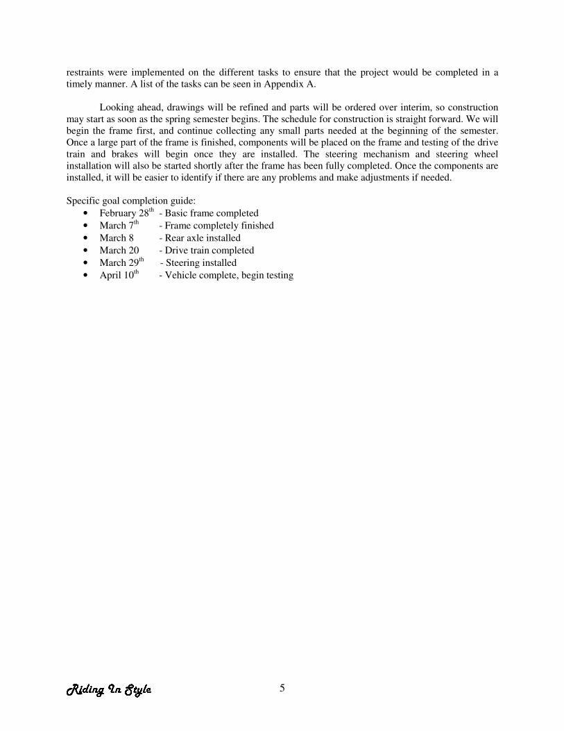
Looking ahead, drawings will be refined and parts will be ordered over interim, so construction may start as soon as the spring semester begins. The schedule for construction is straight forward. We will begin the frame first, and continue collecting any small parts needed at the beginning of the semester. Once a large part of the frame is finished, components will be placed on the frame and testing of the drive train and brakes will begin once they are installed. The steering mechanism and steering wheel installation will also be started shortly after the frame has been fully completed. Once the components are installed, it will be easier to identify if there are any problems and make adjustments if needed. Specific goal completion guide:
• February 28th - Basic frame completed
• March 7th - Frame completely finished
• March 8 - Rear axle installed
• March 20 - Drive train completed
• March 29th - Steering installed
• April 10th - Vehicle complete, begin testing

� � � � � � � � � � � 6
4. Project Breakdown and Management
To begin breaking down this project, we started with an overall picture of what we wanted the vehicle to look like. As Figure 3 and Appendix B shows, there are many different components and parts that are needed to construct an HPV.
Figure 3 – Overall Design View
After having a concept and a sketch, we were able to break the design down into two major components, drive train and vehicle structure. We assigned Phil and Eric M. to design the structure while Josh and Eric S. was assigned to design the drive train. Within these two sections, the project was broken down even further. A detailed breakdown of these sections is discussed in Section 5.
In order to have a successful final prototype where each component fits together, everyone must be in constant communication with the rest of the team. Because the design of any part of a HPV affects the other parts of the HPV, each member of the team must continually be updated with the progress on other sections of the project. Our solution to keep informed was to have a meeting at least once a week, usually at noon on Mondays or in the afternoon on Friday. We also kept notes and a log of the work that had been accomplished, which reminded us where the project was headed.

� � � � � � � � � � � 7
5. Design Process
5.1 Drive Train
5.1.1. General Requirements Our goal for the drive train includes designing a system that will maximize the efficiency of the vehicle. We decided at the beginning of the project that the drive train needed to be composed of only bicycle components for simplicity and for availability of parts. It was our goal to improve on current designs which simply connect the pedals of each rider together, making them turn at the same speed. Gearing on the vehicle should also be sized such that the vehicle can be powered up to 25 mph.
5.1.2. Alternatives
• The first option for the drive train is using a planetary gear system or other type of mechanical drive train that will enable a combined output from the four independent inputs.
• The second option is to have four independent inputs connected to a common rear axle. Each rider would have access to their own gear sets, allowing them to manually adjust their pedaling cadence.
• A third option is having each passenger of the vehicle drive an individual wheel. This would reduce the amount of moving parts and gears as well as the weight without requiring the use of combining inputs.
• A fourth option is to implement the concept of tandem bicycles. The vehicle would ultimately be two tandem bicycles connected together side by side.
• A final option would be similar to option two except in an automatic form.
5.1.3. Selection Our design of the drive train will consist of four pedals each having an independent gear set that is connected to the rear axle. Each rider will be able to manually select which gear they would like to be in, depending on how fast the vehicle is going and how fast they would like to pedal. This configuration was selected because it does the best job at maximizing the effort of each rider. An automatic version of this system would be more beneficial to the riders, but after researching automatic bicycle transmissions we determined that it would be too complex to complete during this class. This configuration should be intuitive to use, since it will be similar to riding a single person bicycle. Individual riders will have the same shifting options as they would have on a common bicycle. The only difference will be that four of these gear sets combine to power one vehicle. Figure 4 shows the layout of the drive train.

� � � � � � � � � � � 8
Figure 4—Drive Train Layout
By giving each rider their own gear selections, they will be able to select the best gear ratio to optimize power going to the rear wheels. This layout also allows for a rider to stop pedaling if they choose. The cassette in on the rear axle will just free spin if a rider decides to not pedal. This would be especially useful on long distance rides, where one or two riders can take a break for a while and the other two keep the vehicle moving.
5.2 Vehicle Structure
5.2.1. Frame 5.2.1.1 General Requirements The frame must be able to handle the load of four adults under driving conditions. Strength and weight considerations need to be carefully balanced in order to keep the vehicle as light as possible without compromising strength. The frame will most likely be subject to corrosive, harsh environments over its life, so it must also have protection against rust. 5.2.1.2 Alternatives
We considered two different frame design options.
• A rectangle or box configuration, with the riders positioned above a frame rail.
• An I configuration, with the users cantilevered out from a central frame rail.
We also considered two different material choices for the frame.
• Steel
• Aluminum
5.2.1.3 Selection Our final selection is the box frame configuration and the material was selected to be aluminum. The box frame configuration was chosen due to its simplicity to manufacture and the ease of mounting seats and pedals. This frame design also provides an adequate mounting surface for supporting the chain.

� � � � � � � � � � � 9
Calculations have been completed in EES for the required size of the frame rails for both aluminum and steel. The calculations for aluminum are shown in appendix B. Considering that aluminum is lighter weight and will not corrode in outside conditions, we have decided that it is a better choice.
5.2.2. Steering 5.2.2.1 General Requirements
The steering system is to provide accurate, stable steering that is easy to operate while
remaining simple to manufacture. The steering system also needs to account for the Ackerman effect by having the front wheels turn on different radii. 5.2.2.2 Alternatives
The two steering options that were considered for the vehicle can be seen below in Figure 5 and
Figure 6. Both systems allow for the front assembly to line up directly with the center point of the rear axle. This approach, shown in appendix C-1, allows the tires to track on the proper radius as the vehicle is
turned. Figure 5 shows a Re-circulating-Ball steering system. This system uses a worm gear, ball bearings and a gearbox to make the wheels turn. Figure 6 shows a rack and pinion steering method. This setup does not have a gear box. The pinion gear is attached to the steering shaft. When the steering wheel is turned, a gear spins, moving the rack. The tie rod at each end of the rack connects to the steering arm on the spindle which turns the wheel. The geometry of the rack and pinion enables the steering to accommodate the Ackerman effect.
Figure 5: Re-circulating-Ball Steering1 Figure 6: Rack-and-Pinion Steering1 5.2.2.3 Selection
The Rack-and-Pinion Steering was selected for a variety of reasons:
• Simplicity: There are less moving parts and fewer rods and arms with the Rack-and-Pinion steering compared to the Re-circulating-Ball steering.
• Weight: It has fewer arms and no gear box. It also weighs less.
• Ease of use: The Rack-and-Pinion steering enables a gear reduction, allowing for a smaller force to turn the wheel.
• Size: The Rack-and-Pinion steering takes up less space.
1 Steering Images from www.howstuffworks.com

� � � � � � � � � � � 10
An EES Sheet (Appendix C.2) shows the derivation of the linkage lengths for the Rack-and-Pinion system.
5.2.3. Wheels 5.2.3.1 General Requirement
The vehicle needs four wheels that will support the designed load and will not fail under heavy side loading. Most often the vehicle will be traveling on a paved surface, so the wheel that is selected should not only have enough traction to stop the vehicle with out skidding, but also minimize rolling friction to make pedaling easier.
5.2.3.2 Alternatives
Some wheel alternatives that were considered are:
• Mountain bike
• Road bike
• Heavy duty BMX
• Camper trailer tires
• Wheel barrow wheels
5.2.3.3 Selection
We selected a 20’’ heavy duty BMX wheel. We knew that any bicycle wheel would be able to
support the static load of the vehicle, but not all of them would support a side load as the vehicle would round a corner. We began researching heavier wheels, but we found that they were too strong and heavy for our application. The best option we found was a BMX wheel. This wheel is light weight, while still providing the side strength that we need. BMX wheels are built especially strong for making jumps off road, so we are confident that they will be an excellent choice for our vehicle.
5.2.4. Braking and Rear Axle
5.2.4.1 General Requirements
A requirement for braking is that they need to effectively stop the vehicle within a safe distance. The braking system also needs to be redundant, so that the vehicle can still be stopped in the event that one brake fails. Weight should be considered in order to maintain the efficiency of the vehicle. The brakes need to be reliable and have a low wear rate, so the owner does not have to worry about them failing or having to replace them. 5.2.4.2 Alternatives
There were several braking options to choose from:
• Car disc brakes
• Bicycle caliper brakes
• Bicycle disc brakes (rubber pads)
• Lawnmower disc brakes
• Motorcycle disc brakes

� � � � � � � � � � � 11
5.2.4.3 Selection
In selecting the brakes that were appropriate for our project, we considered the size, weight, and cost of each alternative. We decided to have two disc brakes mounted on the rear axle or on the two rear wheels. Two brakes were used so that in the case that one failed, the other brake could still stop the vehicle. Figure 7 shows the layout of the rear axle and the location of the disc brakes.
Figure 7 – Rear Axle
We determined bicycle brakes would not give us sufficient braking and they would not be reliable or safe to stop the vehicle. Motorcycle and car brakes were oversized for our application, adding unnecessary weight to the vehicle. The final choice was to use lawnmower disc brakes. These brakes are cable driven, so a cable will run from the calipers in rear to a brake lever in the front by the driver. It is relatively inexpensive to buy the calipers and it is possible to make the discs in the shop at no cost. The analysis of braking power indicated that these brakes will sufficiently stop the vehicle. Figure 8 shows the distance it will take our vehicle to stop given a certain speed and calculations are shown in Appendix D.
Braking Curve Given that the Rear Wheels do not Slip
0
20
40
60
80
100
120
140
5 10 15 20 25 30 35
Velocity (mph)
Sto
pp
ing
Dis
tan
ce (
ft)
Figure 8 – Braking Curve

� � � � � � � � � � � 12
5.2.5. Seating 5.2.5.1 General Requirements
The seats for this vehicle need to be comfortable for the rider, since it is a recreational vehicle. It is important to us that each rider is in an ergonomically correct position as they are riding. Therefore we are making the requirement that adjustability of the seat is built into the design, allowing both tall and short people to be comfortable as they pedal. The seats should allow for sufficient movement of their legs as the riders are pedaling. 5.2.5.2 Alternatives
There are four different seating options available for the vehicle:
• Traditional saddle seats, as used on most single person bicycles.
• Bucket seats, similar to what is found on a lawnmower.
• Bench style seats, similar to what is found on a paddle boat.
• Fabricate seats in the shop.
5.2.5.3 Selection Our final selection is the bucket seats. This option offers the best combination of comfort and safety. Bucket seats are more comfortable than bench seats. They allow for an easy installation of seat belts and will also allow each user to adjust their seat position independently. If cost will be an issue, the contingency plan is to fabricate our own seats using aluminum and fabric.
6. Conclusion
After researching, evaluating our options, and keeping in mind our Christian perspectives, we have determined that the project outlined in this study can be completed by the end of April, 2007. Although our goals have remain unchanged, the design has gone through many changes along the way as different options and ideas have been brought to our attention. As our current design stands, our prototype will be a fully functional vehicle that will meet each of the requirements of the project. Possible additions such as a storage basket, arm rest, speedometer, and lights will be considered after the frame and drive train are complete.

� � � � � � � � � � � 13
7. Resources
Gayle Ermer, Calvin College Engineering Department Greg Bock, Industrial Consultant Sarah Flikkema, Chicago Drive Schwinn www.gocartsupply.com, Light vehicle disc brake information www.hayesdiscbrakes.com, Bicycle disc brake specs Humanscale Body Measurements, Ergonomic charts Keith Heckman, Calvin College Engineering Department www.nashbar.com, Bicycle component pricing Ned Nielson, Calvin College Engineering Department Ren Tubergen, Gumbo Product Development Inc. www.uspto.gov, US patent website, used for researching automatic bicycle transmissions

� � � � � � � � � � � 14
Appendix A – Detailed Project Tasks
Detailed Design
• Vehicle Structure o Obtain bicycles o Steel/Aluminum pricing o Weight/force (engineering) calculations o Tool inventory/machine availability o Wheel/suspension/steering calculations o Style design
� Research enclosure system � Adjustable seats for comfort (Ergonomic charts)
o Cargo space o Drawings o Construction
• Drive Train o Obtain bicycle gears o Gear ratio calculations o Research combining inputs o Cost estimate (pricing) o Integration with frame o Research automatic transmission
� Define type (automatic vs. manual) o Braking system o Research a possible reverse gearing o Drawings
Class Requirements (full semester)
• Determine project
• Website
• Project objective
• Alternative solutions
• Presentation I:5 min
• Presentation II: 10 min
• Preliminary evaluation of feasibility
• Preliminary budget analysis
• Refine task specs/ Product schedule
• Project brief for industrial consultant
• PPFS
• Develop economic model
• Alternative uses

�� �� � � � ��� �� 15
Appendix B – Dimensioned Overall Design

� � � � � � � � � � � 16
Appendix C – Aluminum Frame Calculations
τmax = V
A · 1.5
Max Shear stress
θ max = M · c
I Max Bending Stress
M = L
2 ·
P
2 Max Moment
c = h · 0.5 Effective Length
V = P Loading
δ = P · L
3
48 · E · I Deflection
P = 500 [lbf] Loading
L = 12 · in
ft · 6.5
Length
I = b · h
3
12 –
( b – 2 · t ) · ( h – 2 · t )3
12 Area Moment of Inertia
G = 3.8 x 10 6 [psi]
E = 1 x 10 7 [psi] Modulus of Elasticity
A = b · h – ( ( b – 2 · t ) · ( h – 2 · t ) ) Area
b = 2.5 [in] Width
h = 2.5 [in] Height
t = 0.1875 · 1 [in] Thickness

� � � � � � � � � � � 17
Appendix D – Steering
D-1: Ackerman Model
2
2 Image from www.wikipedia.com

� � � � � � � � � � � 18
D – 2: Linkage Length Calculations
tan ( θ ) = wheelv ert
wheelhoriz
2 Tie Rod-Rear Axle Angle
wheelhoriz = 3.25 [ft] Wheel Base (x Direction)
wheelv ert = 6.5 [ft] Wheel Base (y Direction)
γ = 180 [deg] – θ Geometry Angle
Ψ = γ – 90 [deg] Geometry Angle
cos ( Ψ ) = z
tie rod Tie Rod-Rack Angle
z = 8 [in] Rack-Axle Length
rack = 12 · in
ft · wheelhoriz – tie rod
2 – z
2
Rack Length

� � � � � � � � � � � 19
Appendix E – Braking Calculations
Ff riction · 2 = m · – a Newton’s second law to find
acceleration
m = 1200 [lbm] · 0.453592 · ·kg
lbm Mass of a loaded vehicle
v = 25 · 0.44704 · ·m/s
mile/hr Velocity (metric)
Venglish = v · 2.23694 · mile/hr
m/s Velocity (english)
rwheel = 10 · 0.0254 · m
in Radius of the wheel
0 = v2
+ 2 · a · D Rectilinear motion equation
to find distance D
Denglish = D · 3.28084 · ft
m Stopping Distance
Ff riction = u · N f orce Friction equation
N f orce = m
4 · 9.81 [m/s2]
Normal Force
u = 0.6 Coefficient of Friction
Taxle,no,slip = Ff riction · rwheel · 2 · 8.85075 · ·in–lbf
N–m Torque on the axle with no slip