Project Name Date DVOR/DME for Chumphon, Mae Sot, Buri Ram ...
38
Project Name Date DVOR/DME for Chumphon, Mae Sot, Buri Ram, Krabi Airport April 24, 2017 and Khorat Station. Version 1.0 _______________________________________________________________________________ Scope of Specifications Section 1: Technical Specifications Page 1 1. DEFINITIONS In the specification, the following words and expression shall have the meanings assigned to them hereunder except where the context otherwise requires: AEROTHAI Aeronautical Radio of Thailand Ltd. Essential requirement specification [E] Essential requirement specification which is mandatory requirement by which the Tenderer shall fully comply with AEROTHAI's requirement stipulated in Scope of Specifications. The Proposal will be rejected if the proposed system, functions of features fail to comply with Essential requirement specification. Proposal The response to the requirement specified in Scope of Specifications. Tenderer The juristic person, firm or company who offers to provide materials or perform a service or do a job with AEROTHAI at a specified cost or rate. Contractor The juristic person, firm or company whose Tender(s) /Proposal(s) has/have been accepted by AEROTHAI and who agrees to accomplish the activities for AEROTHAI. ICAO Annex 10 Vol. I Aeronautical Telecommunications: Volume I Radio Navigation Aids. Sixth Edition, July 2006, Amendments 89 ICAO Annex 14 Vol. I Aerodromes: Volume I Aerodrome Design and Operations. Sixth Edition, July 2013, Amendments 11-B ICAO Doc 8071 Vol. I Manual on Testing of Radio Navigation Aids: Volume I Testing of Ground- Based Radio Navigation Systems. Fourth Edition–2000, Amendments 1
Transcript of Project Name Date DVOR/DME for Chumphon, Mae Sot, Buri Ram ...
Project Name Date
DVOR/DME for Chumphon, Mae Sot, Buri Ram, Krabi Airport April 24, 2017
and Khorat Station. Version 1.0
_______________________________________________________________________________
Scope of Specifications Section 1: Technical Specifications Page 1
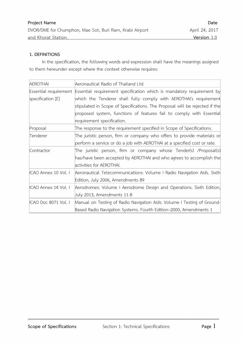
1. DEFINITIONS
In the specification, the following words and expression shall have the meanings assigned to them hereunder except where the context otherwise requires: AEROTHAI Aeronautical Radio of Thailand Ltd. Essential requirement specification [E]
Essential requirement specification which is mandatory requirement by which the Tenderer shall fully comply with AEROTHAI's requirement stipulated in Scope of Specifications. The Proposal will be rejected if the proposed system, functions of features fail to comply with Essential requirement specification.
Proposal The response to the requirement specified in Scope of Specifications. Tenderer The juristic person, firm or company who offers to provide materials or
perform a service or do a job with AEROTHAI at a specified cost or rate.
Contractor The juristic person, firm or company whose Tender(s) /Proposal(s) has/have been accepted by AEROTHAI and who agrees to accomplish the activities for AEROTHAI.
ICAO Annex 10 Vol. I Aeronautical Telecommunications: Volume I Radio Navigation Aids. Sixth Edition, July 2006, Amendments 89
ICAO Annex 14 Vol. I Aerodromes: Volume I Aerodrome Design and Operations. Sixth Edition, July 2013, Amendments 11-B
ICAO Doc 8071 Vol. I Manual on Testing of Radio Navigation Aids: Volume I Testing of Ground-Based Radio Navigation Systems. Fourth Edition–2000, Amendments 1
Project Name Date
DVOR/DME for Chumphon, Mae Sot, Buri Ram, Krabi Airport April 24, 2017
and Khorat Station. Version 1.0
_______________________________________________________________________________
Scope of Specifications Section 1: Technical Specifications Page 2
2. GENERAL REQUIREMENTS [E] 2.1 Five (5) complete system of DVOR/DME (Doppler Very High Frequency Omni
Directional Radio Range/Distance measuring equipment) Systems are required for replacement of the currently used for Chumphon Airport, Mae Sot Airport, Buri Ram Airport, Krabi Airport and Khorat Station.
2.2 The DVOR/DME System shall be designed to operate under dual transmitters and dual monitors configurations. The DVOR/DME system shall consists of the following:
2.2.1 Dual DVOR Equipment; 2.2.2 Dual DME/N Equipment; 2.2.3 Antenna Systems for the above equipment; 2.2.4 Status Indicator for the above equipment specified in 2.2.1-2.2.3 which shall be
equipped in the control room at ATC Tower; 2.2.5 Remote Control and Status Equipment for the above equipment specified in 2.2.1-
2.2.3 which shall be equipped at Technical Control Room; 2.2.6 Remote Maintenance and Monitoring Equipment for the above equipment specified
in 2.2.1-2.2.3 which shall be equipped at Technical Control Room. 2.3 The DVOR/DME System shall have SNMP management capability are specified in clause 6. 2.4 All RF Generators shall be synthesizers. 2.5 The system performance and signal quality shall at least comply with the ICAO Annex 10
Vol. I. 2.6 The equipment shall be the modular design, or an easy plug-in card or modules for quick
replacement with the purpose for easy maintenance and repair.
2.7
The dual independent transmitters shall be housed in the cabinet(s) and operated as main and standby facilities. Maintenance on one equipment shall be accomplished without disruption the operation of the others.
2.8 The equipment shall be designed in common of modules and printed circuit boards. 2.9 The DVOR/DME MTBO shall be greater than 7,000 hours. The Tenderers shall submit
reliability analysis (MTBF, MTBO) of DVOR/DME System in the Proposal. 2.10 The DME equipment shall be installed in co-location with the DVOR equipment and
shall be conformed to DME-DME operation. 2.11 Each Line Replaceable Units (LRU) of DVOR/DME Equipment shall be easily exchangeable. 2.12 Indoor equipment shall be designed for continuous operation at least under the ambient
temperature range of 0 ºC to +50 ºC with a relative humidity of up to 95%. Outdoor equipment shall be designed for continuous operation at least under the
Project Name Date
DVOR/DME for Chumphon, Mae Sot, Buri Ram, Krabi Airport April 24, 2017
and Khorat Station. Version 1.0
_______________________________________________________________________________
Scope of Specifications Section 1: Technical Specifications Page 3
temperature range of -40 ºC to +60 ºC with a relative humidity of up to 100%, up to 100 mph (160 Km/h) wind velocity. All outdoor materials shall be suitably weather protected by appropriate coat or high grade paint in order to withstand severe ambient conditions of outdoor installation due to temperature, humidity, rainfalls, as specified in ICAO Annex 14 Vol. I.
2.13 AC/DC power lines, transmission lines, control lines, test cables and all relevant accessories shall be as follows.
2.13.1 All AC/DC power lines, transmission lines, control lines and relevant accessories (e.g. connectors, cable trays, conduits and cable ties) shall be provided by the contractor. If the installation work involves buried cables, they shall be “underground-type” and fitted in HDPE or RSC pipes which the inner diameter shall be wide enough for fitting all cables easily.
2.13.2 All transmission lines shall be laid in a different pipe separated from that of AC power lines.
2.13.3 The underground cable work shall be done by the Contractor. The trench for lying underground cable shall be dug with more than fifty (50) cms in depth from ground surface and not less than thirty (30) cms in width. The trench basement shall be covered with twenty (20) cms thick of sand which is the base of underground cable. Finally, the underground cable shall be covered with twenty (20) cms thick of sand topping with twenty (20) cms thick of soil.
2.13.4 All known power and control lines (or else cable routes) leading to the facility shall be marked out by the contractor.
2.13.5
Cable route markers shall be installed at every 10 meters for indicating underground cables. The cable route marker specifications are detailed in section 2: Counterpoise and Grounding System Requirements.
2.13.6 All relevant accessories necessary for initial set up, maintenance, or else system calibration (Both transmitter and monitor calibration) shall be provided.
2.13.7 The Contractor shall take all responsible precautions to protect existing underground equipment and utilities.
2.13.8 All RF connectors shall be complied with MIL-PRF-39012 or IEC61169-16 international standard.
2.14 Power supply
2.14.1 The DVOR/DME System and all peripheral equipments shall be operated with 220±10% VAC or better, 50 Hz ±5% single phase.
Project Name Date
DVOR/DME for Chumphon, Mae Sot, Buri Ram, Krabi Airport April 24, 2017
and Khorat Station. Version 1.0
_______________________________________________________________________________
Scope of Specifications Section 1: Technical Specifications Page 4
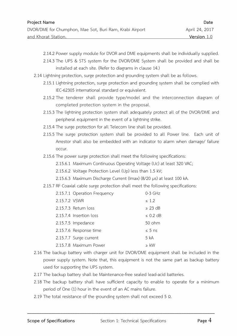
2.14.2 Power supply module for DVOR and DME equipments shall be individually supplied. 2.14.3 The UPS & STS system for the DVOR/DME System shall be provided and shall be
installed at each site. (Refer to diagrams in clause 14.) 2.14 Lightning protection, surge protection and grounding system shall be as follows. 2.15.1 Lightning protection, surge protection and grounding system shall be complied with
IEC-62305 international standard or equivalent. 2.15.2 The tenderer shall provide type/model and the interconnection diagram of
completed protection system in the proposal. 2.15.3 The lightning protection system shall adequately protect all of the DVOR/DME and
peripheral equipment in the event of a lightning strike. 2.15.4 The surge protection for all Telecom line shall be provided. 2.15.5 The surge protection system shall be provided to all Power line. Each unit of
Arrestor shall also be embedded with an indicator to alarm when damage/ failure occur.
2.15.6 The power surge protection shall meet the following specifications: 2.15.6.1 Maximum Continuous Operating Voltage (Uc) at least 320 VAC; 2.15.6.2 Voltage Protection Level (Up) less than 1.5 kV; 2.15.6.3 Maximum Discharge Current (Imax) (8/20 µs) at least 100 kA. 2.15.7 RF Coaxial cable surge protection shall meet the following specifications: 2.15.7.1 Operation Frequency 0-3 GHz
2.15.7.2 VSWR ≤ 1.2
2.15.7.3 Return loss ≥ 23 dB
2.15.7.4 Insertion loss ≤ 0.2 dB
2.15.7.5 Impedance 50 ohm
2.15.7.6 Response time ≤ 5 ns 2.15.7.7 Surge current 5 kA 2.15.7.8 Maximum Power ≥ kW 2.16 The backup battery with charger unit for DVOR/DME equipment shall be included in the
power supply system. Note that, this equipment is not the same part as backup battery used for supporting the UPS system.
2.17 The backup battery shall be Maintenance-free sealed lead-acid batteries. 2.18 The backup battery shall have sufficient capacity to enable to operate for a minimum
period of One (1) hour in the event of an AC mains failure. 2.19 The total resistance of the grounding system shall not exceed 5 Ω.
Project Name Date
DVOR/DME for Chumphon, Mae Sot, Buri Ram, Krabi Airport April 24, 2017
and Khorat Station. Version 1.0
_______________________________________________________________________________
Scope of Specifications Section 1: Technical Specifications Page 5
2.20 The Tenderers shall submit the Signal Coverage Simulation and sites survey data of DVOR/DME System in the Proposal.
3. DOPPLER VHF OMNI RANGE (DVOR) EQUIPMENT [E] 3.1 System Accuracy
3.1.1 Azimuth accuracy shall be better than ±1 degree on ground measurement. 3.1.2 Azimuth stability shall be better than ±0.5 degree measured at a monitor. 3.2 The DVOR equipment shall comprise, but not limited to: 3.2.1 Dual carrier transmitters; 3.2.2 Dual sideband transmitters; 3.2.3 Dual monitors; 3.2.4 DVOR test generator; 3.2.5 Antenna Switching Unit; 3.2.6 Antenna System. 3.3 Carrier Transmitter 3.3.1 Frequency band - 108 MHz to 117.975 MHz
3.3.2 Operating frequency - 110.00 MHz for Chumphon Airport - 116.70 MHz for Mae Sot Airport - 117.20 MHz for Buri Ram Airport - 111.00 MHz for Krabi Airport - 113.70 MHz for Khorat Station
3.3.3 Frequency stability - ± 0.002% from the operating frequency
3.3.4 Output power - at least 50 watts (adjustable) 3.3.5 Spurious output - better than 60 dB below carrier 3.3.6 Carrier modulation: 3.3.6.1 Reference frequency - 30 Hz ± 0.2%
3.3.6.2 Modulation depth - 30% (adjustable) 3.3.6.3 Identification frequency - 1020 Hz ±50 Hz
3.3.6.4 Identification modulation
depth
- 10% (adjustable)
3.3.6.5 Speech channel filter - band pass at the range of 300 to 3000 Hz
within 3 dB relative to the level at 1000 Hz
3.3.6.6 Speech modulation depth - up to 30% (the transmission of speech
shall not interfere in any way with basic
Project Name Date
DVOR/DME for Chumphon, Mae Sot, Buri Ram, Krabi Airport April 24, 2017
and Khorat Station. Version 1.0
_______________________________________________________________________________
Scope of Specifications Section 1: Technical Specifications Page 6
navigation function) (adjustable) 3.3.7 The Identification unit shall be able to generate any three letters International
Morse Code for both DVOR and DME equipment. 3.3.8 The setting up of DVOR Identification code shall be computerized. 3.3.9 The DME Identification shall be generated on every forth DVOR Identification
cycle. 3.3.10 Protection shall be provided for the RF amplifier from damage caused by open
or short circuit of the output. 3.3.11 Thrulines (line sections) with plug-in elements shall be equipped at each RF power
output of the transmitters. One (1) RF Wattmeter shall be provided for RF power reading. Type, model and diagram shall be submitted in the Proposal.
3.4 Sideband Transmitter 3.4.1 A double-sideband DVOR equipment shall be provided. 3.4.2 The Sub-carrier modulation mid-frequency shall be 9960 Hz ±1%. 3.4.3 Phase control circuit shall maintain phase stability between the Sidebands and
carrier signals. 3.4.4 Thrulines (line sections) with plug-in elements shall be equipped at each RF
power output of the transmitters. One (1) RF Wattmeter shall be provided for RF power reading. Type, model and diagram shall be submitted in the Proposal.
3.5 Monitor 3.5.1 The DVOR Monitor system shall be capable continuous monitoring fault (s)
detection and producing alarm signal (s) for the following conditions occurs: 3.5.1.1 A change in excess of 1 degree of the bearing information transmitted
by the DVOR equipment; 3.5.1.2 Reference signal 30 Hz modulation depth exceeds ±2% from the
nominal value; 3.5.1.3 Sub-carrier 9960 Hz modulation depth exceeds ±2% from the nominal
value; 3.5.1.4 Sub-carrier 9960 Hz deviation ratio exceeds 16 ±1. 3.5.2 The bearing alarm limit shall be adjustable with the step of not more than 0.1
degree. 3.5.3 The carrier RF level alarm limit shall be adjustable when the carrier level
decreases 10% to 30% from the nominal value.
Project Name Date
DVOR/DME for Chumphon, Mae Sot, Buri Ram, Krabi Airport April 24, 2017
and Khorat Station. Version 1.0
_______________________________________________________________________________
Scope of Specifications Section 1: Technical Specifications Page 7
3.5.4 The identification alarm shall be provided for the following conditions: 3.5.4.1 Continuous keyed; 3.5.4.2 Loss of identification for more than 15 second (adjustable) 3.5.5 The Monitors shall be configurable such that both monitors are monitoring the
operating (on-antenna) or standby (on-dummy) transmitter simultaneously. 3.5.6 When two Monitors are monitoring the operating transmitter, the Monitors can
be configured either in ‘AND’ mode or ‘OR’ mode for a changeover or shutdown in the event of failure.
3.5.7 The Monitor shall provide a maintenance warning alarm to permit corrective action before an out-of-tolerance condition occurs. The warning indication shall be displayed at the Remote Control and Status Unit (RCSU)
3.5.8 The parameters of DVOR Transmitter and Monitor shall be provided and show on display or indicator lamps. Setting and Selection for display of those parameters shall be done by computerization which is permanently located at site. The following parameters, including but not limited to, shall be available:
3.5.10.1 The bearing information; 3.5.10.2 Reference signal 30 Hz modulation depth; 3.5.10.3 Sub-carrier 9960 Hz modulation depth; 3.5.10.4 Sub-carrier 9960 Hz deviation ratio; 3.5.10.5 Identification; 3.5.10.6 Forward and reflected power or standing wave ratio. 3.5.9 Alarm delay shall be adjustable. 3.5.10 Alarm history shall be provided to identify the parameter that has deviated beyond
the alarm limit and caused the alarm. 3.5.11
The field Monitor (including the Monitor antenna, the Antenna mast, transmission lines with RF surge protection, obstruction lighting) monitoring the radiated composite signal shall be provided for installation at any azimuth suitable for installation. Type, and model shall be submitted in the Proposal.
3.5.12
Double LED obstruction lighting equipment with photo-switch shall be installed at Near-field monitor’s antenna. The LED obstruction lighting equiments shall conforms with the ICAO Annex 14 Vol. I Chapter 6 – Visual Aids For Denoting Obstacles or Federal Aviation Administration (FAA) Specification for Obstruction Lighting Equipment (AC150/5345-43F OR 43G). Type and model shall be submitted in the Proposal.
Project Name Date
DVOR/DME for Chumphon, Mae Sot, Buri Ram, Krabi Airport April 24, 2017
and Khorat Station. Version 1.0
_______________________________________________________________________________
Scope of Specifications Section 1: Technical Specifications Page 8
3.6 Test Generator 3.6.1 The Test Generator for DVOR equipment shall be able to check and calibrate
the monitor to conform with ICAO Annex 10 Vol. I. 3.6.2 Type and model of the Test Generator shall be submitted in the Proposal (in
case of separated unit). 3.6.3 Built-in-Test (BIT) or Fault Diagnostics shall be provided for all Lowest
Replaceable Units (LRU) and capable of being initiated locally and remotely. 3.7 Antenna Switching
3.7.1 The RF Power Distributor in the Antenna Switching unit shall be broadband for operation in the range of 108 MHz to 117.975 MHz.
3.7.2 Surge and Lightning Arrestors shall be provided for all output ports of the distributor.
3.8 Antenna System
3.8.1 The operating frequency of each Antenna element shall be adjusted from the factory.
3.8.2 The Proposal shall describe the method of sideband feed lines fabrication and any other adjustment procedures.
3.8.3 The Antenna VSWR shall not exceed 1.2 : 1 for carrier and 1.2 : 1 for sideband. 3.8.4 The Antenna System shall provide sufficient coverage as required in ICAO Annex 10
Vol. I Paragraph 3.3.4 except where topographical features are dictated.
4. DISTANCE MEASURING EQUIPMENT (DME) [E] 4.1 The DME equipment shall comprise: 4.1.1 Dual transponders; 4.1.2 Dual monitors; 4.1.3 Antenna system. 4.2 DME Transponder 4.2.1 Frequency band - 960 MHz to 1215 MHz
4.2.2 Operating channel - CH 37X for Chumphon Airport - CH 114X for Mae Sot Airport - CH 119X for Buri Ram Airport - CH 47X for Krabi Airport - CH 84X for Khorat Station
4.2.3 Transmitter characteristics
Project Name Date
DVOR/DME for Chumphon, Mae Sot, Buri Ram, Krabi Airport April 24, 2017
and Khorat Station. Version 1.0
_______________________________________________________________________________
Scope of Specifications Section 1: Technical Specifications Page 9
4.2.3.1 The radio frequency of operation shall not vary more than plus or minus 0.002% from the assigned frequency.
4.2.3.2 Pulse shape and spectrum of pulse modulated signal shall meet the requirements for DME/N in ICAO Annex 10 Vol. I Paragraph 3.5.4.1.3. and 3.5.5.1.3
4.2.3.3 Pulse spacing shall meet the requirements specified in ICAO Annex 10 Vol. I Paragraph 3.5.4.1.4.
4.2.3.4 The peak power of the constituen pulse of any pair of pulse shall not differ by more than 1 dB.
4.2.3.5 Peak effective radiation power of the reply pulse shall not be less than 20 dBW.
4.2.3.6 The power amplifier of the transponder shall provide full peak output power of not less than 1000 watts to the antenna.
4.2.3.7 Long distance echo suppressor shall be provided by automatic receiver gain reduction according to each echo pulse level.
4.2.3.8 The minimum transmission rate shall be as close as practicable to 700 PPS. 4.2.3.9 The maximum transmission rate shall be at least 4800 PPS. 4.2.3.10 Identification shall meet the requirements specified in ICAO Annex 10 Vol. I
Paragraph 3.5.3.6 for association with the DVOR identification. 4.2.4 Receiver characteristics 4.2.4.1 The centre frequency of the receiver shall not vary more than plus or
minus 0.002% from the assigned frequency. 4.2.4.2 Interrogation pulse pairs with correct spacing and nominal frequency
shall trigger the transponder if the peak power density at the transponder antenna is at least -103 ±1 dBW/m2 and this value cause the transponder to reply with an efficiency of at least 70% complies with in ICAO Annex 10 Vol. I Paragraph 3.5.4.2.3.1, 3.5.4.2.3.2, 3.5.4.2.3.5 and 3.5.5.3.2.1.
4.2.4.3 Bandwidth and selectivity shall meet the requirements specified in ICAO Annex 10 Vol. I Paragraph 3.5.4.2.6.
4.2.4.4 CW and echo suppression shall be provided and meet the requirements specified in ICAO Annex 10 Vol. I Paragraph 3.5.4.2.9.
4.2.4.5 Interrogating pulse spacing error more than ±2 microseconds shall be rejected.
Project Name Date
DVOR/DME for Chumphon, Mae Sot, Buri Ram, Krabi Airport April 24, 2017
and Khorat Station. Version 1.0
_______________________________________________________________________________
Scope of Specifications Section 1: Technical Specifications Page 10
4.2.4.6 Receiver dead time shall be adjustable as measured after main delay time. 4.2.5 Time Delay
4.2.5.1 The time delay shall meet the requirements specified for DME/N in ICAO Annex 10 Vol. I Paragraph 3.5.4.4.
4.2.5.2 Reply delay, pulse spacing and pulse width shall be adjustable to the specified values without removing any module from the assembly.
4.3 DME Monitor 4.3.1 The Monitor shall serve two purposes. 4.3.1.1 To ensure that the transponder signal is within the tolerance as specified
for DME/N in ICAO Annex 10 Vol. I Paragraph 3.5.4.7.2
4.3.1.2 To be used as a RF signal generator in conjunction with a built-in test unit for calibration, testing and maintenance of the transponder.
4.3.2 The Monitor shall initiate an alarm signal if any of the following conditions occurs: 4.3.2.1 Reply delay error exceed ±0.5 microsecond; 4.3.2.2 Transmitting pulse spacing error exceed ±1 microsecond; 4.3.2.3 Reply efficiency is less than 70%; 4.3.2.4 Effective radiated power (ERP) decreases below by 3 dB; 4.3.2.5 Transmitting pulse count is less than 700 PPS; 4.3.2.6 Continuous or loss of identification. 4.3.3 The occurrence of primary alarm shall initiate a transfer action while the main
transponder is operating (on-antenna) and a shutdown action while the standby transponder is operating (on-antenna). The primary alarms are generated by reply delay error (in 4.3.2.1) or transmitting pulse spacing error (in 4.3.2.2).
4.3.4 The occurrence of secondary alarm shall not initiate a transfer action while the main transponder is operating (on-antenna). The secondary alarms are generated by conditions in 4.3.2.3-4.3.2.6.
4.3.5 The Monitors shall be configurable such that both monitors are monitoring the operating (on-antenna) and standby (on-dummy) transponder simultaneously.
4.3.6 When two Monitors are monitoring the operating transponder, the monitors can be configured either in ‘AND’ mode or ‘OR’ mode for a changeover or shutdown in the event of failure.
4.3.7 Alarm history shall be provided to identify the parameter that has deviated beyond the alarm limit and caused the alarm.
4.3.8 Test signal generator (interrogation) output shall be selected so that the channel
Project Name Date
DVOR/DME for Chumphon, Mae Sot, Buri Ram, Krabi Airport April 24, 2017
and Khorat Station. Version 1.0
_______________________________________________________________________________
Scope of Specifications Section 1: Technical Specifications Page 11
frequency deviation of ± 200 kHz and ± 900 kHz of the transponder receiver can be tested.
4.3.9 Test signal generator (interrogation) output level shall be adjustable at least from -91 dBm to -20 dBm at the transponder antenna connector.
4.3.10 Test signal generator (interrogation) PRF shall be adjustable at least from 700 to 4,800 PPS.
4.3.11 At least the following Transponder and Monitor parameters shall be available for display at the designated control points:
4.3.11.1 Reply delay; 4.3.11.2 Reply pulse pair spacing; 4.3.11.3 Reply efficiency; 4.3.11.4 Transmit power; 4.3.11.5 Transmitter pulse count; 4.3.11.6 Identification. 4.3.12 Settings and selection for display of the Transponder and Monitor parameters in
4.3.11 shall be done by a Desktop Computer refer to 5.2.8. 4.4 DME Antenna System
4.4.1 The radiation patterns of the Antenna System shall be submitted with the Tender. For the horizontal radiation pattern, the antenna shall be omni-directional type. For the vertical radiation pattern, The antenna main lobe shall be maximum at three (3) degrees (see Figure C-20 of [ANNEX 10 / Vol. I/Attachment C/Paragraph 7.2.1]) in Appendix C.
4.4.2 The Antenna shall be capable of radiating DME signal through out the DME frequency band (960 MHz to 1215 MHz) so that changing of the operating frequency needs no readjustment of the Antenna.
4.4.3 The antenna gain shall not be less than +9 dBi. 4.4.4 Double LED obstruction lighting devices with photo-switch shall be installed
with the antenna which conforms either the ICAO Annex 14 Vol. I Chapter 6 – Visual Aids For Denoting Obstacles or Federal Aviation Administration (FAA) Specification for Obstruction Lighting Equipment (AC150/5345-43F or 43G). Type and model shall be submitted in the Proposal.
Project Name Date
DVOR/DME for Chumphon, Mae Sot, Buri Ram, Krabi Airport April 24, 2017
and Khorat Station. Version 1.0
_______________________________________________________________________________
Scope of Specifications Section 1: Technical Specifications Page 12
5. CONTROL AND MONITORING [E] 5.1 DVOR Local Control Unit 5.1.1 The DVOR equipment shall be able to operate on local or remote control. It shall
have at least the following control and monitoring functions: 5.1.1.1 Selecting the main; 5.1.1.2 Turning on/off transmitter; 5.1.1.3 Turning on/off the standby transmitter into dummy loads for testing
purposes; 5.1.1.4 Selecting Remote/Local Control; 5.1.1.5 Resetting the alarm; 5.1.1.6 Shutting down the station; 5.1.1.7 Displaying operating status of the equipment. 5.1.1.8 Bypassing the monitor; 5.1.2 The DVOR Local Control Unit shall automatically transfer from the selected
antenna to a standby antenna and/or shut down in the event of an alarm. 5.1.3 Reset function shall be provided to clear fault condition (s) and restart normal
operation. 5.1.4 Five (5) sets of Desktop Computer shall be provided as part of the Local Control
Unit for DVOR. The Desktop Computer for DVOR shall be provided separately from the Desktop Computer for DME. The Desktop Computer Specifications are specified in clause 11.
5.1.5 The software for monitoring and controlling the DVOR equipment shall be installed in the Desktop Computer. The recovery CD/DVD for the software shall be provided. The user’s license for the software shall be provided for AEROTHAI.
5.2 DME Local Control Unit 5.2.1 The DME equipment shall be able to operate on local or remote control. It
shall have at least the following control and monitoring functions: 5.2.1.1 Selecting the main equipment; 5.2.1.2 Turning on/off transponder; 5.2.1.3 Turning on/off the standby transponder into dummy loads for testing
purposes; 5.2.1.4 Selecting Remote/Local control; 5.2.1.5 Resetting the alarm; 5.2.1.6 Shutting down the station;
Project Name Date
DVOR/DME for Chumphon, Mae Sot, Buri Ram, Krabi Airport April 24, 2017
and Khorat Station. Version 1.0
_______________________________________________________________________________
Scope of Specifications Section 1: Technical Specifications Page 13
5.2.1.7 Displaying the operating status of the equipment. 5.2.1.8 Bypassing the monitor; 5.2.2 The DME Local Control Unit shall automatically transfer from the selected
transponder to a standby transponder and/or shut down in the event of an alarm. 5.2.6 Reset function shall be provided to clear fault condition (s) and restart normal
operation. 5.2.8 Five (5) sets of Desktop Computer shall be provided as part of the Local Control
Unit for DME. The Desktop Computer for DME shall be provided separately from the Desktop Computer for DVOR. The Desktop Computer Specifications are specified in clause 11.
5.2.9 The software for monitoring and controlling the DME equipment shall be installed in the Desktop Computer. The recovery DVD for the software shall be provided. The user’s license for the software shall be provided for AEROTHAI.
5.3 Remote Control and Status Unit (RCSU) 5.3.1 The DVOR/DME RCSU shall have at least the following control and monitoring
functions: 5.3.1.1 Turn on/off the selected transmitter/transponder with indicator; 5.3.1.2 Transfer and shutdown with indicator; 5.3.1.3 NORMAL/ALARM indicator and audible alarm; 5.3.1.4 Alarm silence control with indicator; 5.3.1.5 Alarm reset. 5.3.2 The DVOR/DME RCSU shall be housed in a cabinet suitable for installation on
either desktop or rack in the Technical Control Room at ATC tower. 5.3.3 The DVOR/DME RCSU shall be connected via land line (provided by AEROTHAI)
and the outdoor wireless link (5.150-5.850 GHz) (provided by the Contractor). 5.3.4 The wireless link between the DVOR/DME station and the Technical Control Room
for the RCSU shall be installed. The wireless link specification is specified in clause 7.3
5.3.5 The selection capability for using the land line or the outdoor wireless link as the main communication link between DVOR/DME equipment and the Technical Control Room shall be provided.
5.3.6 Surge and lightning protection shall be provided at both ends of land line and the outdoor wireless link. Type, model and diagram shall be submitted in the Proposal. Refer to 2.14.2
Project Name Date
DVOR/DME for Chumphon, Mae Sot, Buri Ram, Krabi Airport April 24, 2017
and Khorat Station. Version 1.0
_______________________________________________________________________________
Scope of Specifications Section 1: Technical Specifications Page 14
5.4 DVOR/DME Remote Status Unit (RSU) 5.4.1 The DVOR/DME RSU shall be provided with audible alarm, that located in the
control room at ATC tower. 5.4.2 The DVOR/DME RSU shall have at least the following features: 5.4.2.1 Display the operating status of the DVOR/DME; 5.4.2.2 Visual and audible alarm with an alarm silence control; 5.4.2.3 Turn on/off switch for the status indicator. 5.5 DVOR/DME Remote Monitoring and Maintenance Equipment (RMM) 5.5.1 The RMM Equipment shall monitor and control DVOR/DME equipment by TCP/IP. 5.5.2 The RMM Equipment shall have at least the following functions for each
equipment: 5.5.2.1 Selecting the main transmitter/transponder; 5.5.2.2 Turning on/off transmitters/transponders; 5.5.2.3 Turning on the standby transmitter/transponder into dummy loads for
testing purposes; 5.5.2.4 Bypassing the monitor; 5.5.2.5 Resetting the alarm; 5.5.2.6 Shutting down the station; 5.5.2.7 Adjusting and displaying transmitter/transponder and monitor parameters. 5.5.3 The RMM Equipment shall be interfaced to DVOR/DME station via land line
(provided by AEROTHAI) and TCP/IP network with the outdoor wireless link (provided by the Contractor) as specified in clause 7.3.
5.5.4 The communication for the RMM must be separated from that for the RCSU for redundancy.
5.5.5 The wireless link between the DVOR/DME station and the Technical Control Room for the RMM shall be installed. The operating frequency of the wireless link shall be adjustable within the band UHF 5.150-5.850 GHz by users. The air link shall be at least AES 128 bits encryption.
5.5.6 The RMM Surge and Lightning protection shall be provided at both ends of the Land line and the outdoor wireless link. Type, model and diagram of the Surge and Lighting protection shall be submitted in the Proposal.
5.5.7 The RMM Equipment shall be performed by Notebook Computer or Desktop Computer.
Project Name Date
DVOR/DME for Chumphon, Mae Sot, Buri Ram, Krabi Airport April 24, 2017
and Khorat Station. Version 1.0
_______________________________________________________________________________
Scope of Specifications Section 1: Technical Specifications Page 15
5.5.8 Five (5) sets of Desktop Computer and Five (5) sets of Notebook Computer shall be provided as part of the Remote Monitoring and Maintenance. The Desktop and Notebook Computer Specifications are specified in clause 11 and 12 respectively.
5.5.9 The RMM Equipment software for remote monitoring and controlling the DVOR/DME equipment from anywhere shall be installed in the Notebook Computer and the Desktop Computer. The recovery CD/DVD or any portable data storage devices for the RMM software shall be provided. The user’s license for the software shall be provided for AEROTHAI.
5.5.10 Five (5) sets of Color Printers for making hard copy report of the station status and meter reading shall be provided as part of the RMM equioment.
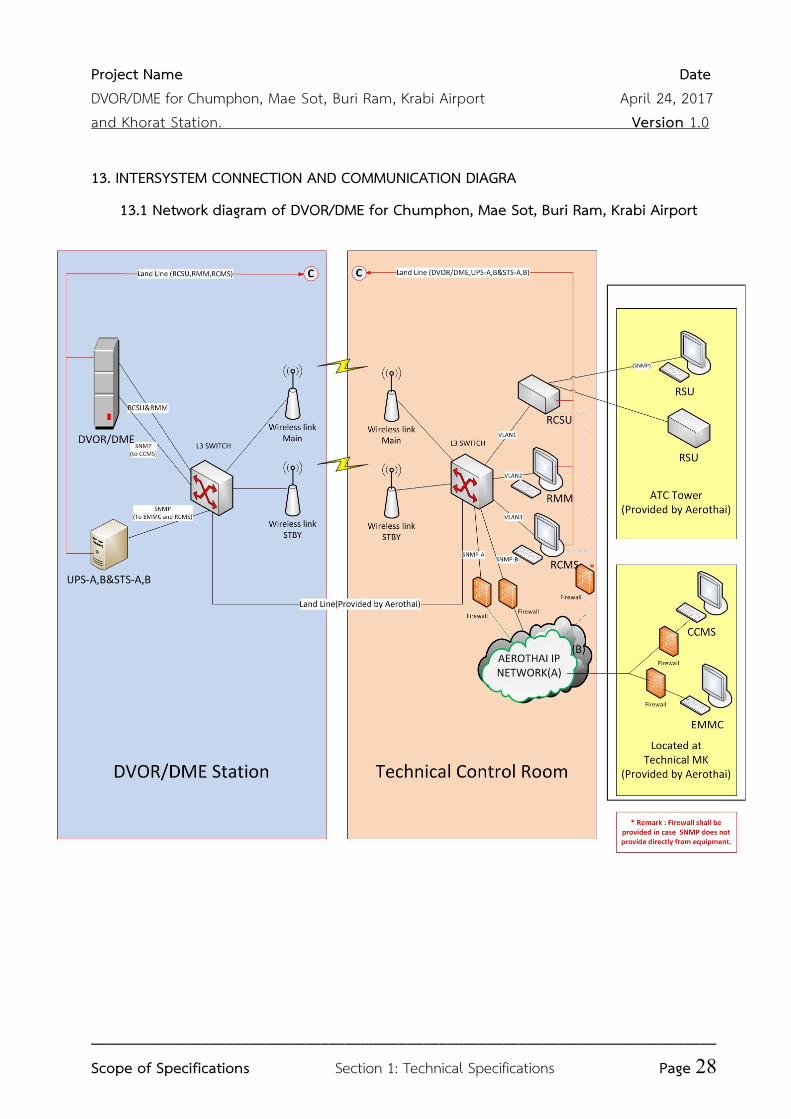
6. INTERSYSTEM CONNECTION
6.1 The DVOR/DME System and UPS&STS system shall be connected with RCSU and RCMS (Provided by the contractor), CCMS and EMMC (provided by AEROTHAI) to send update information.
6.2 The Update information shall comprise at least the system operation status, as specified in clause 5.1.5, 5.2.4 and 10.3.7.1 by using at least the Simple Network Management Protocol (SNMP) over Ethernet port as specified in clause 13.
6.3 The Tenderer shall provide and detail the DVOR/DME/UPS&STS – RCMS, CCMS, EMMC information exchange.
6.4 The Tenderer shall provide and detail the mechanism to provide data integrity and security against unauthorized access, intrusion and malicious computer attacks.
6.5 The Tenderer shall provide network equipment and communication link details for inter-system connection (DVOR/DME/UPS&STS to RCMS, CCMS and EMMC) to AEROTHAI network at Technical Control Room as depicted in the clause 13.
6.6 The Contractor shall provide a list of all necessary standards documents and Interface Control Documents (ICDs) with regards to the DVOR/DME/UPS&STS – RCMS, CCMS and EMMC information exchange.
6.7 Specifications of Network Equipment for DVOR/DME, UPS &STS Systems [E] This section will detail all the network equipment necessary for implementing the
REMOTE monitoring & control system. The monitoring & control equipment for DVOR/DME, UPS&STS is described in clause 5. The complete “Intersystem Connection and Communication Diagram” is described in clause 13.
Project Name Date
DVOR/DME for Chumphon, Mae Sot, Buri Ram, Krabi Airport April 24, 2017
and Khorat Station. Version 1.0
_______________________________________________________________________________
Scope of Specifications Section 1: Technical Specifications Page 16
6.7.1 Firewall and VPN Router Specifications The tenderers shall propose the technical specifications of the Firewall and VPN
Router which comply with or are better than the following specifications. 6.7.1.1 Categorized as Next Generation Firewall Appliance. 6.7.1.2 Have at least 1 Console port. 6.7.1.3 At least 8 ports of 10/100/1000 Mbps Base-T
6.7.1.4 Firewall throughput with Application Control shall not be less than 250 Mbps.
6.7.1.5 Firewall throughput with IPS shall not be less than 100 Mbps. 6.7.1.6 VPN throughput (IPSec Encryption) shall be at least 50 Mbps. 6.7.1.7 Capable of IPSec tunneling for at least 50 tunnels 6.7.1.8 Support IPv4 and IPv6
6.7.1.9 Support Static, RIP, OSPFv2/v3 with graceful restart, BGP with graceful restart routing protocols.
6.7.1.10 Support Bidirectional Forwarding Detection (BFD) 6.7.1.11 Support Point-to-Point Protocol over Ethernet (PPPoE). 6.7.1.12 Support Routing Policy-based forwarding
6.7.1.13 Support IPv4 Network Address Translation (NAT) with both static and dynamic IP, and support Port Address Translation (PAT).
6.7.1.14 Capable of Dynamic Site-to-Site IPSec VPN configuration
6.7.1.15 Support the following IPSec Key Exchange types: Manual Key, Pre-shared Key, Certificate-based.
6.7.1.16 Support 3DES and AES (128 bits, 256 bits) IPSec Encryption. 6.7.1.17 Support the following IPSec Authentication types: MD5, SHA-1, SHA-256,
SHA-384, SHA-512
6.7.1.18 Capable of creating at least 4000 VLANs each of which complies with 802.1q standard
6.7.1.19 Can be configured in link aggregation which complies with IEEE 802.3ad standard.
6.7.1.20 Support Active/Passive High Availability. 6.7.1.21 At least 50 GB of internal storage
6.7.1.22 Manageable with CLI, GUI, SSH, SNMPv2c/3
6.7.1.23 Compatible with 220 V 50 Hz power
Project Name Date
DVOR/DME for Chumphon, Mae Sot, Buri Ram, Krabi Airport April 24, 2017
and Khorat Station. Version 1.0
_______________________________________________________________________________
Scope of Specifications Section 1: Technical Specifications Page 17
6.7.2 L3 Switch Specifications The Tenderers shall propose the technical specifications of the L3 Switch
which comply with or are better than the following specifications. 6.7.2.1 Capable of switching and routing in both Layer 2 (data link) and Layer 3
(network) 6.7.2.2 Forwarding bandwidth or Switching Capacity shall be at least 100 Gbps. 6.7.2.3 Have at least 24 ports of RJ45 Gigabit Ethernet (10/100/1000 Mbps). 6.7.2.4 2 ports of SFP Gigabit Ethernet or better, and 1 port of LX SFP
6.7.2.5 The switch must be stackable up to 8 stack members. 6.7.2.6 The stack throughput shall be up to 80 Gbps. 6.7.2.7 Support 1,000 concurrent active VLANs or better. 6.7.2.8 Can contain at least 8,000 MAC addresses. 6.7.2.9 Support both IPv4 and IPv6. 6.7.2.10 Support Static, RIP, RIPng, OSPFv2, OSPFv3 routing protocols. 6.7.2.11 Configurable Access Control List for both IPv4 and IPv6
6.7.2.12 Support IEEE 802.1X security authentication. 6.7.2.14 Can be configured in link aggregation which complies with IEEE 802.3ad
standard. 6.7.2.15 Support Spanning Tree protocol as specified in IEEE 802.1D standard. 6.7.2.16 Capable of both ingress and egress port mirroring from a port on either
the same device or other devices. 6.7.2.17 Manageable with CLI, GUI, SSH, SNMPv2c/3. 6.7.2.18 Compatible with 220 V 50 Hz power.
7. SUPPLEMENTS
7.1 Portable Navigational Signal Analyzer (PNSA) [E] 7.1.1 Five (5) sets of Portable Navigational Signal Analyzer shall be provided. They shall
be used for ground test of the ILS, VOR and Marker beacon. Each PNSA shall comprises:
7.1.1.1 Receiver for Localizer, Glide Slope, VOR and Marker Beacon; 7.1.1.2 Built-in rechargeable battery; 7.1.1.3 Antennas for Localizer, Glide Slope and VOR; 7.1.1.4 Battery Charger; 7.1.1.5 Antenna Pole;
Project Name Date
DVOR/DME for Chumphon, Mae Sot, Buri Ram, Krabi Airport April 24, 2017
and Khorat Station. Version 1.0
_______________________________________________________________________________
Scope of Specifications Section 1: Technical Specifications Page 18
7.1.1.6 Accessories. 7.1.2 The PNSA shall be designed for outdoor purpose with compact and weatherproof. 7.1.3 All ILS/VOR channels shall be selectable. 7.1.4 Performance analyzer of ILS Localizer, Glide Slope, Marker Beacon and VOR shall be
performed in accordance with ICAO Doc 8071 Vol. I. 7.1.5 All parameters shall be printed out directly or export to the external portable
storage media e.g. HD/USB drive or other devices in text format. 7.1.6 The PNSA shall be provided real time measurement data directly via RS 232 C or
USB port. 7.1.7 PNSA shall be provided with the Interface Control Document (ICD) for extracting or
decoding the real time measurement data. 7.1.8 Battery charger shall be operated on 220 ±10 VAC, 50 Hz ±5%
7.2 Wireless Link Radio Equipment [E] 7.2.1 The wireless link between the DVOR/DME station and the Technical Control Room
for the Remote Control and Status (RCSU) and Remote Maintenance and Monitoring (RMM) shall be provided.
7.2.2 Radio
7.2.2.1 Frequency range : 5.150–5.850 GHz
7.2.2.2 Channel bandwidth : ≥ 20 MHz
7.2.3 Data communication
7.2.3.1 The air link shall be at least AES 128 bits encryption.
7.2.3.2 VLAN support : 802.1 q
7.2.3.3 Maximum throughput : ≥ 20 Mbps
7.2.4 Antenna & Transmission line shall be provided.
7.3 DVOR Spare Parts 7.3.1 Five (5) sets of DVOR spare parts shall be provided. 7.3.2 The DVOR spare parts in 7.3.1 shall consist of one complete unit which is under
single system configuration. The one complete unit shall consist of line replaceable module (LRM), printed circuit boards (PCBs), backplanes and RF switches (Coaxial relays), RF distribution units.
7.4 DME Spare Parts 7.4.1 Five (5) sets of DME spare parts shall be provided.
Project Name Date
DVOR/DME for Chumphon, Mae Sot, Buri Ram, Krabi Airport April 24, 2017
and Khorat Station. Version 1.0
_______________________________________________________________________________
Scope of Specifications Section 1: Technical Specifications Page 19
7.4.2 The DME spare parts in 7.4.1 shall consist of one complete unit which is under single system configuration. The one complete unit shall consist of line replaceable module (LRM), printed circuit boards (PCBs), backplanes and RF switches (Coaxial relays).
7.5 RCSU and RSU Spare Parts 7.5.1 Five (5) sets of RCSU and RSU spare parts shall be provided. 7.5.2 The RCSU and RSU spare parts in 7.5.1 shall consist of one complete unit of each
line replaceable module (LRM), printed circuit boards (PCBs) and backplanes. 7.6 Wireless Link Equipment Spare Parts Six (6) Wireless Link Equipments shall be provided as spare parts. 7.7 The network equipment Spare Parts 7.7.1 Five (5) set of Firewall and VPN router shall be provided as spare parts. (see clause
6.7.1) 7.7.2 Five (5) set of L3 Switch shall be provided as spare part. (see clause 6.7.2) 7.8 Double LED obstruction lighting Spare Parts (in clause 3.5.12 and 4.4.4) Ten (10) sets of Double LED obstruction lighting equipment shall be provided as spare
parts.
8. TOOLS KITS AND MAINTENANCE AIDS
8.1 For system installation and hardware adjustment, tool kits and maintenance aids list as specified in Appendix B per DVOR/DME system shall be provided.
8.2 A suitable waveform analysis tool, thruline wattmeter and digital multimeter tool shall be provided, with functions including but not limited to, as specified in Appendix B.
8.3 Ten (10) sets for Portable RF power analysis shall be provided as specified in Appendix B.
8.4 Extension cables and cards as required for each module/ PCB of the DVOR/DME shall be provided for maintenance.
8.5 Test cables, dummy loads and attenuation kits for transmitter calibration and flight inspection shall be provided.
8.6 Installation materials such as external and internal cablings, cable trays, connectors, cable ties and conduits shall be provided.
9. TECHNICAL DOCUMENTS AND TEST REPORTS [E] The Contractor shall provide the following drawing documents:
Project Name Date
DVOR/DME for Chumphon, Mae Sot, Buri Ram, Krabi Airport April 24, 2017
and Khorat Station. Version 1.0
_______________________________________________________________________________
Scope of Specifications Section 1: Technical Specifications Page 20
9.1 Six (6) sets for hard copy and Six (6) DVD sets for mechanical and electrical DVOR/DME drawings and whole network diagrams essential for installation, maintenance and troubleshooting of the equipment, including such drawings as are needed to identify the components and cable within the equipment or its sub units;
9.2 Seven (7) sets for hard copy and Seven (7) sets for DVD, of DVOR/DME installation and equipment instruction manuals, setting out in detail the procedures for operation, routine maintenance, troubleshooting of the equipment, test and alignment procedures, including schematics and inter-cabling diagrams;
9.3 Six (6) sets of hard copy and DVD for DVOR/DME component part lists which cludes manufacturer part numbers or descriptions of any generic component level devices (ICs, transistors, capacitors, etc.) in each Line Replaceable Modules (LRMs) shall be provided
for the propose of comparing for the generic devices with electronic component in the market in order to repair the LRMs after the warranty period.
9.4 One (1) original and Five (5) hard copies of Factory Acceptance Test (FAT) report shall be provided at the factory after the completion of FAT.
9.5 Five (5) original and Six (6) hard copies of Site Acceptance Test (SAT) report shall be provided at the site after the completion of the commissioning flight check.
10. UNINTERRUPTED POWER SUPPLY AND STATIC TRANSFER SWITCH (UPS & STS) 10.1 General Requirements 10.1.1 At minimum, the full UPS configuration shall consists of the components as
depicted in the clause 14. 10.1.2 Two (2) sets of UPS Equipments for each site shall be provided. 10.1.3 Two (2) sets of STS (Static Transfer Switch) equipments for each site shall be
provided. 10.1.4 Each set of UPS equipment, alone, shall provide enough electric power capacity
for all equipments in the facility for a minimum of 15 minutes. 10.1.5 The Tenderer shall be responsible for electric current load calculation for each
facility and each set of UPS equipment. 10.1.6 The Tenderer shall propose and detail the connection between UPS to
equipments in clause 14. 10.1.7 The Tenderer shall propose the list of UPS Equipments and related components. 10.1.8 The Contractor shall be responsible to demonstrate a complete full load field
test.
Project Name Date
DVOR/DME for Chumphon, Mae Sot, Buri Ram, Krabi Airport April 24, 2017
and Khorat Station. Version 1.0
_______________________________________________________________________________
Scope of Specifications Section 1: Technical Specifications Page 21
10.1.9 The Contractor shall be responsible to demonstrate that the UPS system compatible with AEROTHAI emergency backup generator
10.1.10 The Contractor shall provide, install, and test a complete and operable UPS system in specified locations.
10.1.11 The STS shall connect to both sets of UPS equipments to receive electric power supply as depicted in the clause 14.
10.1.12 The STS shall automatically select electric power from available UPS to equipments in the condition that one of UPS is disfunctional.
10.1.13 The Tenderer shall provide product description/Technical Characteristics of UPS systems, STS and other related components.
10.1.14 All UPS&STS equipment shall be new and factory tested. 10.2 Characteristics of UPS
10.2.1 The UPS shall be True On-Line Type with Double Conversion. 10.2.2 The UPS shall be provided with protection against overcharging, over current and
short-circuit, spill proof, maintenance free and with capability of latching shutdown on overload.
10.2.3 In the event of a main electric power failure, the battery shall automatically take over without any interruption of the system operation.
10.2.4 When UPS failure or overload is occurs, it shall be able to automatically transfer the load supplied by the inverter to the reserve line without any interruption of the system operation.
10.2.5 Manual bypass switch shall be provided for maintenance purpose. When the manual bypass switch is selected, the system shall be able to operate without any interruption of the system operation.
10.2.6 The Tenderer shall provide the detailed connection diagram between UPS system at DVOR/DME station to RCMS at the Technical Control Room and EMMC.
10.2.7 The Contractor shall provide ICDs of the connection between UPS system at DVOR/DME station to the RCMS and EMMC at the Technical Control Room
10.2.8 The RCMS shall be provided with the facility to authorized user in order to monitor and control the functionality and system devices of the UPSs.
10.2.9 Both audible and visual alarm indications shall be provided upon detection of RCMS equipment fault and/or any out of tolerance parameters in the monitoring equipment.
10.2.10 The visual alarm shall remain on RCMS until the fault is resolved.
Project Name Date
DVOR/DME for Chumphon, Mae Sot, Buri Ram, Krabi Airport April 24, 2017
and Khorat Station. Version 1.0
_______________________________________________________________________________
Scope of Specifications Section 1: Technical Specifications Page 22
10.2.11 The SNMP usage shall be encouraged for RCMS function. 10.2.12 The UPS shall send update information of system status warning, alarm messages
and monitor parameters using SNMP protocol via AEROTHAI network to CCMS and EMMC.
10.2.13 The Tenderers shall provide the detailed connection diagram between UPS at DVOR/DME station to CCMS and EMMC.
10.2.14 The Contractor shall provide ICDs of the connection between UPS at DVOR/DME station to CCMS and EMMC.
10.2.15 The Tenderer shall provide network equipment and communication link and details for inter-system connection (UPS&STS to CCMS and EMMC) to AEROTHAI network at Technical Control Room as depicted in the clause 13.
10.2.16 The UPS System at DVOR/DME site shall be connected via land line (provided by AEROTHAI) and the outdoor wireless link (5.150-5.850 GHz) (provided by the Contractor) as specified in clause 13.
10.2.17 Protection shall be provided against damage of semiconductors due to the battery polarity being inadvertently reversed.
10.2.18 The battery charger shall be capable of charging batteries which are completely discharged.
10.2.19 The battery shall be continuously float charged. 10.3 Technical Requirements 10.3.1 Input 10.3.1.1 Voltage : 220 VAC or 230 VAC ±15% or better 10.3.1.2 Frequency : 50 Hz ±5% or better 10.3.1.3 Phase : Single (2 Wire + Ground) 10.3.2 Output 10.3.2.1 Voltage : 220 VAC or 230 VAC ±15%
10.3.2.2 Frequency : 50 Hz ±0.5%
10.3.2.3 Phase : Single (2 Wire + Ground) 10.3.2.4 Wave Form : Sine wave
10.3.2.5 Total harmonics distortion : ≤ 3 % for 100% Linear Load
10.3.2.6 Overall efficiency : ≥ 84% at load
10.3.2.7 AC to AC-Crest factor : 3:1 or better 10.3.3 Overload capacity-120% Load : 1 Min or better
Project Name Date
DVOR/DME for Chumphon, Mae Sot, Buri Ram, Krabi Airport April 24, 2017
and Khorat Station. Version 1.0
_______________________________________________________________________________
Scope of Specifications Section 1: Technical Specifications Page 23
10.3.4 Environment 10.3.4.1 Ambient temperature : 0-40 ºC (Continuous) or better 10.3.4.2 Humidity : ≥ 90% continuously with non-
condensing
10.3.5 Audible noise : ≤ 55 dB(A) at 1 m. 10.3.6 Battery
10.3.6.1 Type : Maintenance free sealed lead acid
10.3.6.2 Discharge : High rate discharge
10.3.6.3 Life time : ≥ 4 years at 25º C
10.3.6.4 Back up time : ≥ 15 minutes at full load of UPS
10.3.7 Status and Control Indicator the capability, including but not limited to, shall be as follows.
10.3.7.1 Display status and parameters, line input, inverter, output, load on bypass, battery and fault;
10.3.7.2 Provide visual and audible alarm when main fail, low battery and overload;
10.3.7.3 Enable and disable alarm. 10.4 Technical specification of STS
10.4.1 Input Voltage (Vrms) : 220 VAC±10% (adjustable) or better 10.4.2 Output Voltage (Vrms) : 220 VAC±10% (adjustable) or better 10.4.3 Frequency : 50 Hz ± (5% or better) 10.4.4 Phase : Single (2 Wire + Ground) 10.4.5 Rating : STS 32 A for UPS 5 KVA or,
: STS 45 A for UPS 10 KVA
10.4.6 Transfer time : ≤ 5 ms for automatic transfer ≤ 10 ms for manual transfer
10.4.7 Overload Capacity (110%) : 1 minute or better 10.4.8 Standard : IEC 62310 series (or compatible) 10.4.9 Communication port : RS232 standard and TCP/IP
11. DESKTOP COMPUTER
The Tenderers shall provide the Desktop Computer including all attached devices that are installed for system operation and monitoring. The Tenderers shall propose the technical specifications of Desktop Computer which comply with or better than the following specifications.
Project Name Date
DVOR/DME for Chumphon, Mae Sot, Buri Ram, Krabi Airport April 24, 2017
and Khorat Station. Version 1.0
_______________________________________________________________________________
Scope of Specifications Section 1: Technical Specifications Page 24
11.1 Desktop, Display and Keyboard shall be produced form the same manufacturer with permanent logo/ brand on products.
11.2 Processor/ Chip set 11.2.1 6th Generation Intel Core i5
11.2.2 Base clock frequency – 3.2 GHz
11.3 RAM
11.3.1 Technology – DDR 4 SDRAM
11.3.2 Memory speed – 2133 MHz
11.3.3 Capacity – 8 GB
11.4 One (1) Hard disk Drive
11.4.1 Capacity –1.0 TB
11.4.2 ATA Interface – Serial ATA
11.5 One (1) Optical Disc Drive
Internal DVD +/- RW Drive
11.6 Graphic Controller Built-in graphic 11.7 One (1) Display
21.5 inches LED with resolution 1920 x 1080 pixels 11.8 Networking
11.8.1 Built-in on board
11.8.2 10/100/1000 Mbps Ethernet 11.8.3 RJ-45 Interface type
11.9 Audio Output Sound output including speakers 11.10 I/O Interfaces 11.10.1 Minimum USB3.0 port-2 ports 11.10.2 Minimum total USB ports including USB2.0, USB3.0, USB3.1-4 ports 11.10.3 One (1) Serial ports or One (1) conversion device for converting USB to Serial
port 11.11 One (1) Keyboard
11.11.1 Standard QWERTY keyboard with USB interface
11.11.2 104 keys at minimum
11.11.3 Each key shall be permanently printed with both Thai and English characters
Project Name Date
DVOR/DME for Chumphon, Mae Sot, Buri Ram, Krabi Airport April 24, 2017
and Khorat Station. Version 1.0
_______________________________________________________________________________
Scope of Specifications Section 1: Technical Specifications Page 25
11.12 One (1) Mouse
11.12.1 Optical Mouse with scroll wheel 11.12.2 USB interface
11.12.3 A suitable mouse pad
11.13 Operation System/ Software
11.13.1 Shall be installed with the Desktop Computer 11.13.2 Capable of operating with the software of the proposed DVOR/DME System
11.13.3 Recovery DVD with a copy right shall be provided
11.14 Compliant Standards FCC or UL or CSA or ETL
11.15 The Operating System and License which is capable of operating the DVOR/DME System shall be provided.
11.16 One (1) set of Office table and chair which is suitable for computer operation shall be provided.
11.17 The Contractor shall provide to the Desktop Computer a two (2) years Manufacturer warranty which starts from the completion of the fifth payment date according to the term of payment stipulated in non-technical term of reference.
11.18 The Desktop Computer shall have a manufacturer branch office authorized representative in Thailand.
11.19 The manufacture of the Desktop Computer shall receive ISO 9000 Series Certification. 11.20 The DVD for software driver shall be provided with the product.
12. NOTEBOOK COMPUTER
The Tenderers shall provide the Notebook Computer including all attached devices that are installed for system operation and monitoring. The Tenderers shall propose the technical specifications of Notebook Computer which comply with or better than the following specifications. 12.1 Processor/ Chip set 12.1.1 6thGeneration Intel Core i7
12.1.2 Base clock frequency: 2.5 GHz
12.2 RAM
12.2.1 Technology: DDR3 or DDR4 SDRAM
12.2.2 Memory speed : 1600 MHz for DDR3 or 2133 MHz for DDR4 12.2.3 Capacity: 8 GB
Project Name Date
DVOR/DME for Chumphon, Mae Sot, Buri Ram, Krabi Airport April 24, 2017
and Khorat Station. Version 1.0
_______________________________________________________________________________
Scope of Specifications Section 1: Technical Specifications Page 26
12.3 One (1) Hard disk Drive
12.3.1 Capacity: 1.0 TB
12.3.2 ATA Interface: Serial ATA
12.4 One (1) Optical Disc Drive
Internal DVD +/- RW Drive
12.5 Graphic Controller AMD graphic with a minimum of 2 GB dedicated memory
12.6 One (1) Display
14 or 15 inches LED with resolution 1366 x 768 pixels 12.7 Internal Wireless LAN
Compliant with IEEE 802.11b/g/n standards
12.8 Networking
12.8.1 Built-in on board
12.8.2 10/100/1000 Mbps Ethernet 12.8.3 RJ-45 interface type
12.9 Audio Output Sound output including built-in stereo speakers 12.10 I/O Interfaces 12.10.1 Minimum USB3.0 port – 1 port 12.10.2 Minimum total USB ports including USB2.0, USB3.0, USB3.1 – 3 ports 12.10.3 One (1) Serial port or One (1) conversion device for converting USB to Serial port 12.10.4 One (1) VGA port, or One (1) conversion device for converting existing display
output port to VGA port 12.12 One (1) Keyboard Each key shall be permanently printed with both Thai and English characters 12.13 One (1) Mouse
12.13.1 Optical Mouse with scroll wheel 12.13.2 USB interface
12.13.3 A Suitable mouse pad
12.14 Pointing Device
Touch pad
12.15 Battery
Lithium Ion rechargeable
Project Name Date
DVOR/DME for Chumphon, Mae Sot, Buri Ram, Krabi Airport April 24, 2017
and Khorat Station. Version 1.0
_______________________________________________________________________________
Scope of Specifications Section 1: Technical Specifications Page 27
12.16 Operation System/ Software
12.16.1 Shall be installed with the Notebook Computer 12.16.2 Capable of operating with the software of the proposed DVOR/DME System
12.16.3 Recovery DVD with a copy right shall be provided
12.17 Compliant Standards FCC or UL or CSA or ETL
12.18 The Operating System and License which is suitable for operation shall be provided. 12.19 The Notebook Computer shall have a manufacturer branch office authorized
representative in Thailand. 12.20 The manufacture of the Notebook Computer shall receive ISO 9000 Series Certification. 12.21 Operating Manual and the DVD for software driver shall be provided with the product. 12.22 One (1) suitable-sized carrying case shall be provided with the Notebook Computer. 12.22 The weight of Notebook Computer including battery shall not exceed 2.5 Kilograms. 12.23 The Contractor shall provide to the Notebook Computer a two (2) years Manufacturer
warranty which starts from the completion of the fifth payment date according to the term of payment stipulated in non-technical term of reference.
Project Name Date
DVOR/DME for Chumphon, Mae Sot, Buri Ram, Krabi Airport April 24, 2017
and Khorat Station. Version 1.0
_______________________________________________________________________________
Scope of Specifications Section 1: Technical Specifications Page 28
13. INTERSYSTEM CONNECTION AND COMMUNICATION DIAGRA
13.1 Network diagram of DVOR/DME for Chumphon, Mae Sot, Buri Ram, Krabi Airport
Project Name Date
DVOR/DME for Chumphon, Mae Sot, Buri Ram, Krabi Airport April 24, 2017
and Khorat Station. Version 1.0
_______________________________________________________________________________
Scope of Specifications Section 1: Technical Specifications Page 29
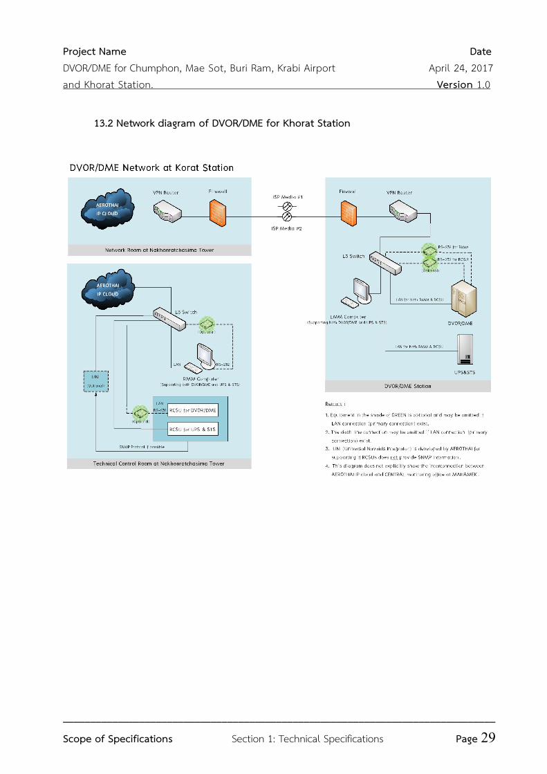
13.2 Network diagram of DVOR/DME for Khorat Station
Project Name Date
DVOR/DME for Chumphon, Mae Sot, Buri Ram, Krabi Airport April 24, 2017
and Khorat Station. Version 1.0
_______________________________________________________________________________
Scope of Specifications Section 1: Technical Specifications Page 30
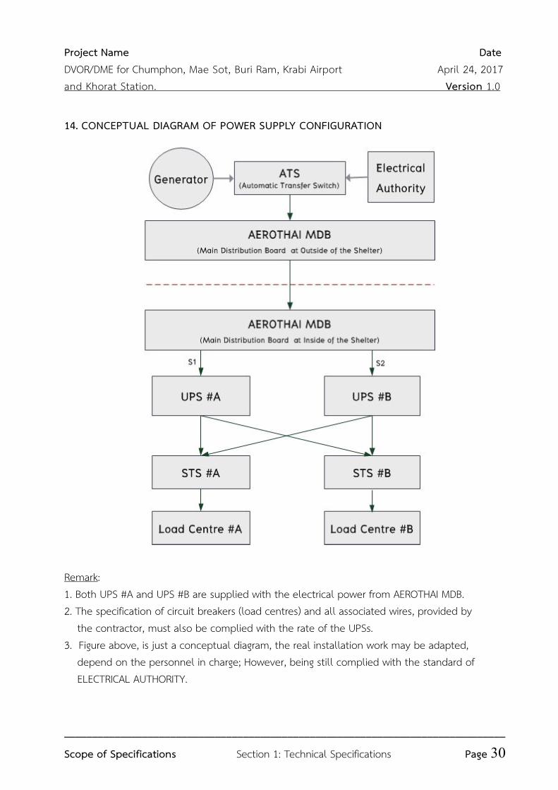
14. CONCEPTUAL DIAGRAM OF POWER SUPPLY CONFIGURATION
Remark: 1. Both UPS #A and UPS #B are supplied with the electrical power from AEROTHAI MDB. 2. The specification of circuit breakers (load centres) and all associated wires, provided by the contractor, must also be complied with the rate of the UPSs. 3. Figure above, is just a conceptual diagram, the real installation work may be adapted, depend on the personnel in charge; However, being still complied with the standard of ELECTRICAL AUTHORITY.
Project Name Date
DVOR/DME for Chumphon, Mae Sot, Buri Ram, Krabi Airport April 24, 2017
and Khorat Station. Version 1.0
_______________________________________________________________________________
Scope of Specifications Section 1: Technical Specifications Page 31
APPENDIX A: LIST OF ABBREVIATIONS
Abbreviations Full Name
ºC Degree Celsius
AC Alternating Current AEROTHAI Aeronautical Radio of Thailand Ltd. CCMS Central Control and Monitoring System
cms Centimeters CW Continuous Wave
dB Decibel DDM Difference in Depth of Modulation
DME Distance Measuring Equipment DVOR Doppler Very High Frequency Omni-directional Range
EMMC Electrical Monitoring and Management Center FAA Federal Aviation Administration
GHz Giga Hertz GS Glide Slope
Hz Hertz
HDPE High Density Polyethylene
ICAO International Civil Aviation Organization
ICD Interface Control Document ILS Instrument Landing System
Imax Maximum Discharge Current Intl International kVA Kilo Volt Amp
kms Kilometers kHz Kilo Hertz
MHz Mega Hertz MTBF Mean Time Between Failure
MTBO Mean Time Between Outage
mph Mile per hour µs Microsecond
PABX Private Automatic Branch Exchange
Project Name Date
DVOR/DME for Chumphon, Mae Sot, Buri Ram, Krabi Airport April 24, 2017
and Khorat Station. Version 1.0
_______________________________________________________________________________
Scope of Specifications Section 1: Technical Specifications Page 32
Abbreviations Full Name
PCB Printed Circuit Board
PMDT Portable Maintenance Data Terminal PNSA Portable Navigational Signal Analyzer PVNA Portable Vector Network Analyzer RCMS Remote Control and Monitoring System
RCSU Remote Control and Status Unit RF Radio Frequency
RSC Rigid Steel Conduit RSU Remote Status Unit RMM Remote Monitoring and Maintenance
SNMP Simple Network Management Protocol. SDM Sum in Depth of Modulation
STS Static Transfer Switch or one (1) Source Transfer Switch
Uc Maximum Continuous Operating Voltage
Up Voltage Protection Level UHF Ultra High Frequency
UPS Uninterrupted Power Supply
USB Universal Serial Bus VAC Voltage of Alternating Current VOR Very high frequency Omni-directional Range
Project Name Date
DVOR/DME for Chumphon, Mae Sot, Buri Ram, Krabi Airport April 24, 2017
and Khorat Station. Version 1.0
_______________________________________________________________________________
Scope of Specifications Section 1: Technical Specifications Page 33
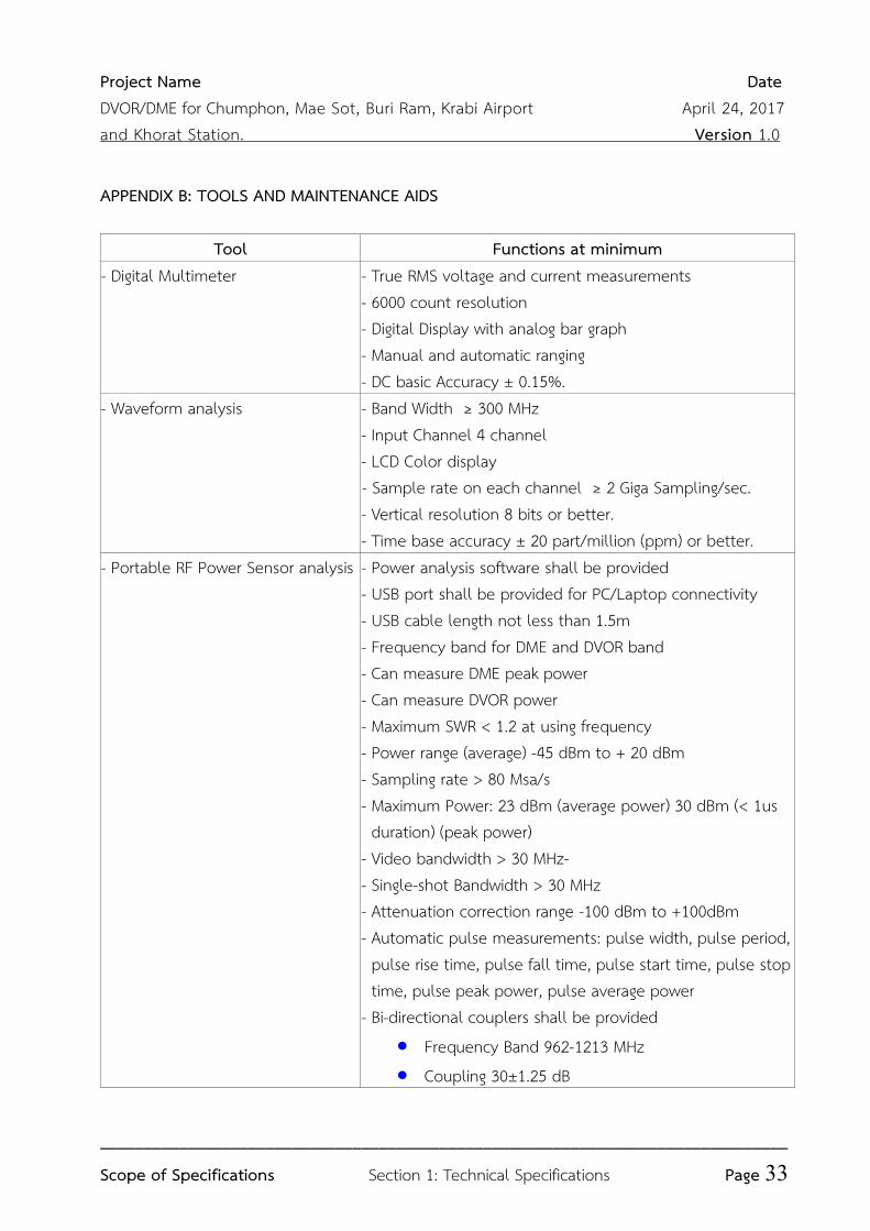
APPENDIX B: TOOLS AND MAINTENANCE AIDS
Tool Functions at minimum
- Digital Multimeter - True RMS voltage and current measurements - 6000 count resolution
- Digital Display with analog bar graph
- Manual and automatic ranging
- DC basic Accuracy ± 0.15%. - Waveform analysis - Band Width ≥ 300 MHz
- Input Channel 4 channel - LCD Color display
- Sample rate on each channel ≥ 2 Giga Sampling/sec. - Vertical resolution 8 bits or better. - Time base accuracy ± 20 part/million (ppm) or better.
- Portable RF Power Sensor analysis - Power analysis software shall be provided
- USB port shall be provided for PC/Laptop connectivity
- USB cable length not less than 1.5m - Frequency band for DME and DVOR band
- Can measure DME peak power - Can measure DVOR power - Maximum SWR < 1.2 at using frequency
- Power range (average) -45 dBm to + 20 dBm
- Sampling rate > 80 Msa/s - Maximum Power: 23 dBm (average power) 30 dBm (< 1us duration) (peak power) - Video bandwidth > 30 MHz- - Single-shot Bandwidth > 30 MHz
- Attenuation correction range -100 dBm to +100dBm
- Automatic pulse measurements: pulse width, pulse period, pulse rise time, pulse fall time, pulse start time, pulse stop time, pulse peak power, pulse average power - Bi-directional couplers shall be provided
• Frequency Band 962-1213 MHz
• Coupling 30±1.25 dB
Project Name Date
DVOR/DME for Chumphon, Mae Sot, Buri Ram, Krabi Airport April 24, 2017
and Khorat Station. Version 1.0
_______________________________________________________________________________
Scope of Specifications Section 1: Technical Specifications Page 34
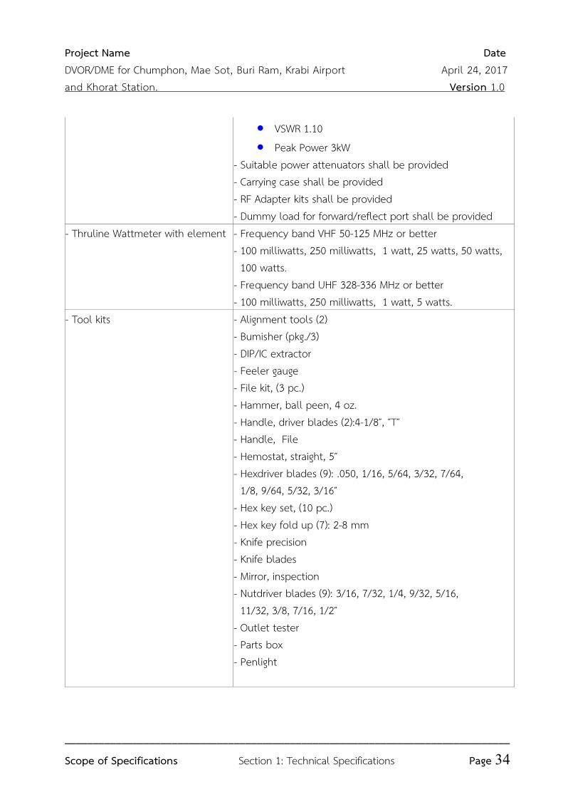
• VSWR 1.10
• Peak Power 3kW
- Suitable power attenuators shall be provided
- Carrying case shall be provided
- RF Adapter kits shall be provided
- Dummy load for forward/reflect port shall be provided
- Thruline Wattmeter with element
- Frequency band VHF 50-125 MHz or better - 100 milliwatts, 250 milliwatts, 1 watt, 25 watts, 50 watts, 100 watts. - Frequency band UHF 328-336 MHz or better - 100 milliwatts, 250 milliwatts, 1 watt, 5 watts.
- Tool kits - Alignment tools (2) - Bumisher (pkg./3) - DIP/IC extractor - Feeler gauge
- File kit, (3 pc.) - Hammer, ball peen, 4 oz. - Handle, driver blades (2):4-1/8″, ″T″ - Handle, File
- Hemostat, straight, 5″ - Hexdriver blades (9): .050, 1/16, 5/64, 3/32, 7/64, 1/8, 9/64, 5/32, 3/16″ - Hex key set, (10 pc.) - Hex key fold up (7): 2-8 mm
- Knife precision
- Knife blades - Mirror, inspection
- Nutdriver blades (9): 3/16, 7/32, 1/4, 9/32, 5/16, 11/32, 3/8, 7/16, 1/2″ - Outlet tester - Parts box
- Penlight
Project Name Date
DVOR/DME for Chumphon, Mae Sot, Buri Ram, Krabi Airport April 24, 2017
and Khorat Station. Version 1.0
_______________________________________________________________________________
Scope of Specifications Section 1: Technical Specifications Page 35
Tool Functions at minimum
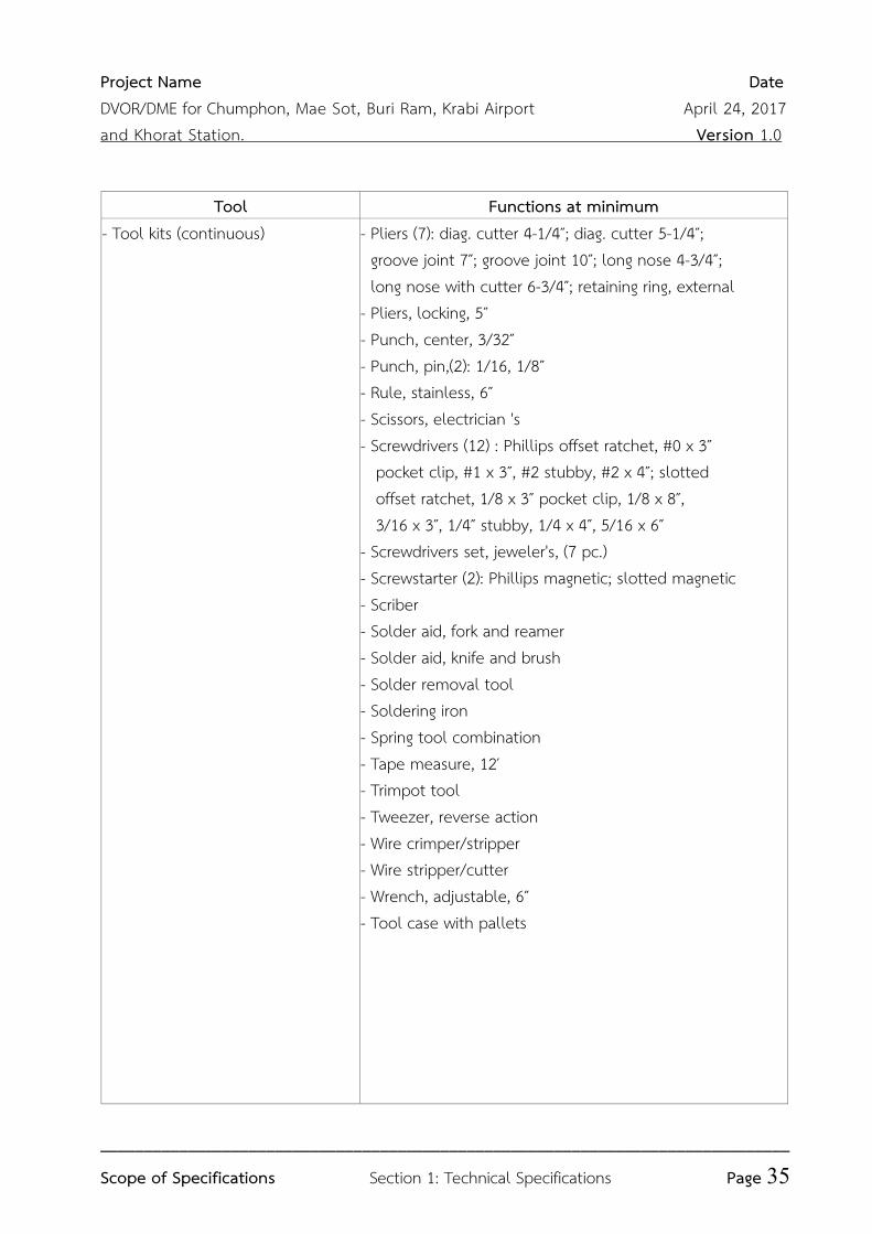
- Tool kits (continuous)
- Pliers (7): diag. cutter 4-1/4″; diag. cutter 5-1/4″; groove joint 7″; groove joint 10″; long nose 4-3/4″; long nose with cutter 6-3/4″; retaining ring, external - Pliers, locking, 5″ - Punch, center, 3/32″ - Punch, pin,(2): 1/16, 1/8″ - Rule, stainless, 6″ - Scissors, electrician 's - Screwdrivers (12) : Phillips offset ratchet, #0 x 3″ pocket clip, #1 x 3″, #2 stubby, #2 x 4″; slotted
offset ratchet, 1/8 x 3″ pocket clip, 1/8 x 8″, 3/16 x 3″, 1/4″ stubby, 1/4 x 4″, 5/16 x 6″ - Screwdrivers set, jeweler's, (7 pc.) - Screwstarter (2): Phillips magnetic; slotted magnetic
- Scriber - Solder aid, fork and reamer - Solder aid, knife and brush
- Solder removal tool - Soldering iron
- Spring tool combination
- Tape measure, 12′ - Trimpot tool - Tweezer, reverse action
- Wire crimper/stripper - Wire stripper/cutter - Wrench, adjustable, 6″ - Tool case with pallets
Project Name Date
DVOR/DME for Chumphon, Mae Sot, Buri Ram, Krabi Airport April 24, 2017
and Khorat Station. Version 1.0
_______________________________________________________________________________
Scope of Specifications Section 1: Technical Specifications Page 36
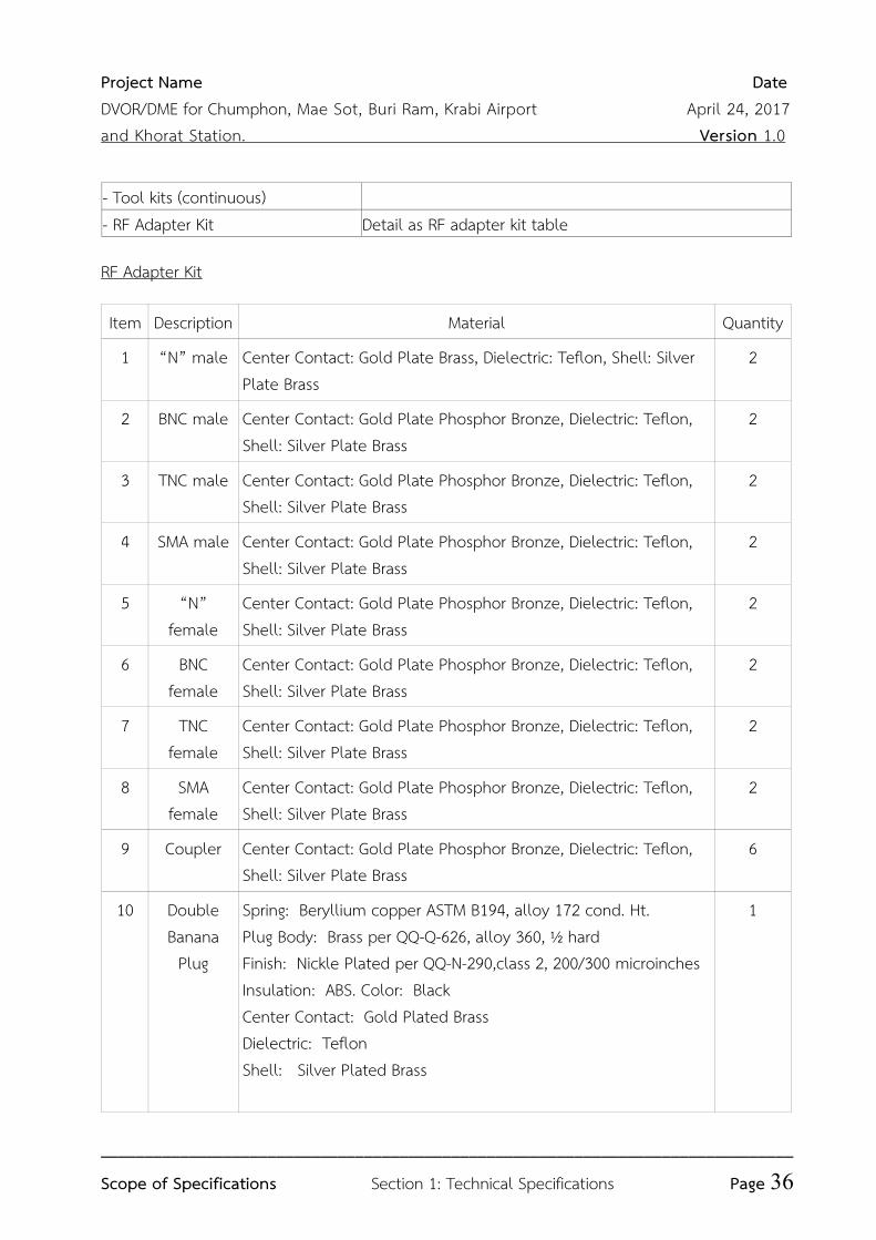
- Tool kits (continuous) - RF Adapter Kit Detail as RF adapter kit table
RF Adapter Kit
Item Description Material Quantity
1 “N” male Center Contact: Gold Plate Brass, Dielectric: Teflon, Shell: Silver Plate Brass
2
2 BNC male Center Contact: Gold Plate Phosphor Bronze, Dielectric: Teflon, Shell: Silver Plate Brass
2
3 TNC male Center Contact: Gold Plate Phosphor Bronze, Dielectric: Teflon, Shell: Silver Plate Brass
2
4 SMA male Center Contact: Gold Plate Phosphor Bronze, Dielectric: Teflon, Shell: Silver Plate Brass
2
5 “N” female
Center Contact: Gold Plate Phosphor Bronze, Dielectric: Teflon, Shell: Silver Plate Brass
2
6 BNC female
Center Contact: Gold Plate Phosphor Bronze, Dielectric: Teflon, Shell: Silver Plate Brass
2
7 TNC female
Center Contact: Gold Plate Phosphor Bronze, Dielectric: Teflon, Shell: Silver Plate Brass
2
8 SMA female
Center Contact: Gold Plate Phosphor Bronze, Dielectric: Teflon, Shell: Silver Plate Brass
2
9 Coupler Center Contact: Gold Plate Phosphor Bronze, Dielectric: Teflon, Shell: Silver Plate Brass
6
10 Double Banana
Plug
Spring: Beryllium copper ASTM B194, alloy 172 cond. Ht. Plug Body: Brass per QQ-Q-626, alloy 360, ½ hard
Finish: Nickle Plated per QQ-N-290,class 2, 200/300 microinches Insulation: ABS. Color: Black
Center Contact: Gold Plated Brass Dielectric: Teflon
Shell: Silver Plated Brass
1
Project Name Date
DVOR/DME for Chumphon, Mae Sot, Buri Ram, Krabi Airport April 24, 2017
and Khorat Station. Version 1.0
_______________________________________________________________________________
Scope of Specifications Section 1: Technical Specifications Page 37
11 Double Binding Post
Body: Brass per QQ-Q-626, alloy 360, ½ hard
Finish: Nickle Plated per QQ-N-290,class 2, 200/300 microinches Insulation: Polycarbonate. Color: one black, one red
Insulation, Body: ABS. Color: Black
Center Contact: Gold Plated Brass Dielectric: Teflon
Shell: Silver Plated Brass
1
12 UHF male Center Contact: Gold Plate Phosphor Bronze, Dielectric: Teflon, Shell: Silver Plate Brass
2
13 UHF female
Center Contact: Gold Plate Phosphor Bronze, Dielectric: Teflon, Shell: Silver Plate Brass
2
14 Mini UHF male
Center Contact: Gold Plate Phosphor Bronze, Dielectric: Teflon, Shell: Silver Plate Brass
2
15 Mini UHF female
Center Contact: Gold Plate Phosphor Bronze, Dielectric: Teflon, Shell: Silver Plate Brass
2
16 RCA male Center Contact: Gold Plate Phosphor Bronze, Dielectric: Teflon, Shell: Silver Plate Brass
2
17 RCA female
Center Contact: Gold Plate Phosphor Bronze, Dielectric: Teflon, Shell: Silver Plate Brass
2
18 “F” male Center Contact: Gold Plate Phosphor Bronze, Dielectric: Teflon, Shell: Silver Plate Brass
2
19 “F” female Center Contact: Gold Plate Phosphor Bronze, Dielectric: Teflon, Shell: Silver Plate Brass
2
20 Signal Simpler
Center Contact: Gold Plate Phosphor Bronze, Dielectric: Teflon, Shell: Silver Plate Brass
1
21 Carrying case
1
** RF Adapter kit shall deliver to Tungmahamek
Project Name Date
DVOR/DME for Chumphon, Mae Sot, Buri Ram, Krabi Airport April 24, 2017
and Khorat Station. Version 1.0
_______________________________________________________________________________
Scope of Specifications Section 1: Technical Specifications Page 38
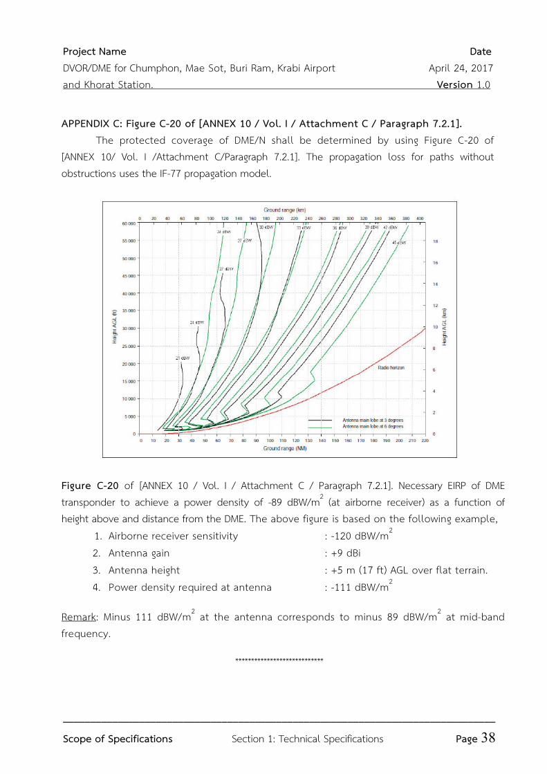
APPENDIX C: Figure C-20 of [ANNEX 10 / Vol. I / Attachment C / Paragraph 7.2.1]. The protected coverage of DME/N shall be determined by using Figure C-20 of [ANNEX 10/ Vol. I /Attachment C/Paragraph 7.2.1]. The propagation loss for paths without obstructions uses the IF-77 propagation model.
Figure C-20 of [ANNEX 10 / Vol. I / Attachment C / Paragraph 7.2.1]. Necessary EIRP of DME transponder to achieve a power density of -89 dBW/m2 (at airborne receiver) as a function of height above and distance from the DME. The above figure is based on the following example, 1. Airborne receiver sensitivity : -120 dBW/m2
2. Antenna gain : +9 dBi 3. Antenna height : +5 m (17 ft) AGL over flat terrain. 4. Power density required at antenna : -111 dBW/m2
Remark: Minus 111 dBW/m2 at the antenna corresponds to minus 89 dBW/m2 at mid-band frequency.
****************************