PROJECT NAME CONTRACTORS OPERATIONS & MAINTENANCE MANUAL · PDF fileELECTRICAL PROJECT NAME...
28
ELECTRICAL PROJECT NAME CONTRACTORS OPERATIONS & MAINTENANCE MANUAL NAME Manual.doc Pages inc. any attach. 1 of 28 PROJECT PROJECT NAME SUBURB STATE DOCUMENT OPERATIONS & MAINTENANCE MANUAL ELECTRICAL SERVICES CONTRACTOR CONTRACTORS NAME STREET ADDRESS SUBURB STATE CONSULTANT ELECTRICAL DESIGN GROUP PO BOX 15, SHERWOOD Q 4075 ELECTRICAL CONTRACTOR CONTRACTORS NAME STREET ADDRESS SUBURB STATE DESCRIPTION REVISION: A DATE: 1 JUNE 2003
Transcript of PROJECT NAME CONTRACTORS OPERATIONS & MAINTENANCE MANUAL · PDF fileELECTRICAL PROJECT NAME...
ELECTRICAL PROJECT NAME CONTRACTORS OPERATIONS & MAINTENANCE MANUAL NAME
Manual.doc Pages inc. any attach. 1 of 28
PROJECT
PROJECT NAME SUBURB STATE DOCUMENT
OPERATIONS & MAINTENANCE MANUAL ELECTRICAL SERVICES CONTRACTOR
CONTRACTORS NAME STREET ADDRESS SUBURB STATE CONSULTANT
ELECTRICAL DESIGN GROUP PO BOX 15, SHERWOOD Q 4075 ELECTRICAL CONTRACTOR
CONTRACTORS NAME STREET ADDRESS SUBURB STATE DESCRIPTION
REVISION: A DATE: 1 JUNE 2003

ELECTRICAL PROJECT NAME CONTRACTORS OPERATIONS & MAINTENANCE MANUAL NAME
Manual.doc Pages inc. any attach. 2 of 28
SECTION CONTENTS PAGE 1.0 PROJECT DETAILS 3 2.0 LICENCES & CERTIFICATES 7 3.0 OPERATING INSTRUCTIONS 8 4.0 MAINTENANCE INSTRUCTIONS 11 5.0 LIGHTING 19 6.0 GENERAL ELECTRICAL COMPONENTS 20 7.0 POWER DISTRIBUTION 21 8.0 AS BUILT DRAWINGS 23 9.0 EMERGENCY LIGHTING 24 10.0 TEST RESULTS 26 11.0 FIRE ALARM SYSTEM 27
ELECTRICAL PROJECT NAME CONTRACTORS OPERATIONS & MAINTENANCE MANUAL NAME
Manual.doc Pages inc. any attach. 3 of 28
1.0 PROJECT DETAILS
1.1 PROJECT DESCRIPTION This section is to include a description of the project and the works carried our as part of the electrical sub contract. This section is to include a description of the contract and the contractual relationships associated with the project. Supply and installation of new MSB and MAINS Supply and installation of tenancy distribution boards DB-A & DB-B Supply and installation of general purpose power outlets Supply and installation of telecommunication block facility cabling Supply and installation of lighting Supply and installation of access/area lighting Supply and installation Ram cold room alarm system Supply and installation on switching panels Supply and Installation of conduit access system Supply and Installation of Emergency and Evac. Lighting system Testing and commissioning of the installation As constructed drawings and operation & maintenance manuals 1.2 MANUAL DESCRIPTION This Operation and Maintenance Manual is intended to provide the user with sufficient information to enable them to perform any tasks necessary to maintain or repair any of the systems installed. Covered within this manual is the work carried out as the contract between the contractor and the electrical sub contractor. As this manual consists largely of manufacturer supplied installation, operation and maintenance booklets and manuals, and excerpts from supplier catalogues, the pages are not numbered sequentially as this would cause confusion when referring to a manual or catalogue index which lists page numbers specific to itself.

ELECTRICAL PROJECT NAME CONTRACTORS OPERATIONS & MAINTENANCE MANUAL NAME
Manual.doc Pages inc. any attach. 4 of 28
1.3 CONTACTS The electrical installation is covered by a defects and liability warranty until 30 June 2002 provided by: Service All electrical services covered within this manual. Company Name Address Phone Fax Contact Mobile Once the defects and liability warranty has expired record the electrical services maintenance and service company details in the following table: Service Company Name Address Phone Fax Contact Mobile Service Company Name Address Phone Fax Contact Mobile Service Company Name Address Phone Fax Contact Mobile Service Company Name Address Phone Fax Contact Mobile

ELECTRICAL PROJECT NAME CONTRACTORS OPERATIONS & MAINTENANCE MANUAL NAME
Manual.doc Pages inc. any attach. 5 of 28
1.4 SUPPLIERS The following are the contact details for the various suppliers to the electrical installation. It is common that the manufacturer of a specific item is not the local supplier for the project. As such the manufacturer may not have any record of the project. Service Electrical Sub Contractor Company Name Address Phone Fax Contact Mobile Service Light Fittings Company Name Address Phone Fax Contact Mobile Service Lamps Company Name Address Phone Fax Contact Mobile Service Switchboards Company Name Address Phone Fax Contact Mobile Service Cables Company Name Address Phone Fax Contact Mobile

ELECTRICAL PROJECT NAME CONTRACTORS OPERATIONS & MAINTENANCE MANUAL NAME
Manual.doc Pages inc. any attach. 6 of 28
Service Outlets Company Name Address Phone Fax Contact Mobile Service Company Name Address Phone Fax Contact Mobile Service Company Name Address Phone Fax Contact Mobile Service Company Name Address Phone Fax Contact Mobile Service Company Name Address Phone Fax Contact Mobile Service Company Name Address Phone Fax Contact Mobile
ELECTRICAL PROJECT NAME CONTRACTORS OPERATIONS & MAINTENANCE MANUAL NAME
Manual.doc Pages inc. any attach. 7 of 28
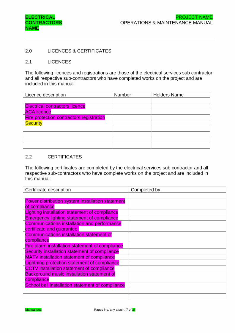
2.0 LICENCES & CERTIFICATES 2.1 LICENCES The following licences and registrations are those of the electrical services sub contractor and all respective sub-contractors who have completed works on the project and are included in this manual: Licence description Number Holders Name Electrical contractors licence ACA licence Fire protection contractors registration Security 2.2 CERTIFICATES The following certificates are completed by the electrical services sub contractor and all respective sub-contractors who have complete works on the project and are included in this manual: Certificate description Completed by Power distribution system installation statement of compliance
Lighting installation statement of compliance Emergency lighting statement of compliance Communications installation and performance certificate and guarantee.
Communications installation statement of compliance
Fire alarm installation statement of compliance Security installation statement of compliance MATV installation statement of compliance Lightning protection statement of compliance CCTV installation statement of compliance Background music installation statement of compliance
School bell installation statement of compliance

ELECTRICAL PROJECT NAME CONTRACTORS OPERATIONS & MAINTENANCE MANUAL NAME
Manual.doc Pages inc. any attach. 8 of 28
3.0 OPERATING INSTRUCTIONS 3.1 OPERATION
Provide a description of the operation of the electrical installation. 3.2 SAFE WORKING PROCEDURES If for any reason a fault does arise, a qualified electrician must be obtained for investigation into the fault and correction. During the warranty period the electrical sub contractor identified in section 1.3 should be contacted immediately if a fault condition exists. A qualified electrician must be used for all electrical problems. Their knowledge would be adequate for the isolation of power, diagnoses of fault and to permit repair work to be carried out safely. Only suitably qualified personnel should carry out inspections and work. Safety rules (as published by the supply and authority, plant manufacturer etc) should be understood and followed. First aid notices giving instructions for the treatment of persons suffering from the effects of electric shock should be on prominent display. First aid equipment should be readily available. Safety lockouts and or tagging systems to isolate circuits must be used. 3.3 ENVIRONMENT The room or area in which the switchboard is installed should be kept clean and dry. The entry and build-up of dust and moisture can lead to malfunction of equipment, notwithstanding the enclosure rating of the switchboard. Entry and exit doors etc, should be kept clear and clearly identified on both sides. Lighting should be maintained at an adequate level. Fire extinguishing equipment should be in place, and the use and techniques understood. Temperature and humidity should be maintained within the limits that the switchboard was specified to operate in. 3.4 LIGHTING Describe the operation of the lighting installation considering the following: Control. Lamp life. 3.5 POWER Describe the operation of the power installation considering the following:

ELECTRICAL PROJECT NAME CONTRACTORS OPERATIONS & MAINTENANCE MANUAL NAME
Manual.doc Pages inc. any attach. 9 of 28
Isolation. Circuit protection. RCDs. Should a circuit or submain experience a fault the protective circuit breaker will trip with the handle moving from the on position to the tripped position. To reset the protective circuit breaker the handle must be moved into the off position to reset the circuit breaker and then moved into the on position. Any tripping of a protective circuit breaker must be considered as the circuit breaker working correctly and protecting the installation against a potentially dangerous fault. As such all circuit breaker trips must be attended to by a qualified electrician and the cause for the trip must be identified and rectification work must be undertaken. 3.6 COMMUNICATIONS Describe the operation of the communications installation considering the following: Exchange services. System configuration. Jumpering and patching. 3.7 INTRUDER DETECTION Describe the operation of the intruder detection system considering the following: Intruder detection system description. Monitoring. Arming and disarming. Clearing alarms. Programming. 3.8 CCTV Describe the operation of the CCTV system considering the following: CCTV system description. Camera aiming and focusing. Monitoring and recording. Viewing and playback. 3.9 MATV Describe the operation of the MATV system considering the following: MATV system description. 3.10 BACKGROUND MUSIC Describe the operation of the background music system considering the following:
ELECTRICAL PROJECT NAME CONTRACTORS OPERATIONS & MAINTENANCE MANUAL NAME
Manual.doc Pages inc. any attach. 10 of 28
Background music system description. Source selection. Zone selection. Volume control. Microphone control. 3.11 LIGHTNING PROTECTION Describe the operation of the lighting protection system considering the following: Lightning protection system description. 3.12 SCHOOL BELL SYSTEM Describe the operation of the school bell system considering the following: School bell system description. Programming Volume control 3.13 FIRE ALARM SYSTEM Describe the operation of the fire alarm system considering the following: Fire alarm system description Monitoring. Clearing of alarms. Evacuation procedure. 3.14 ELECTRICAL SAFETY AT WORK Following is a copy of the Department of Employment, Training and Industrial Relations, Electrical Safety At Work brochure and a copy of a First Aid Hints brochure.

ELECTRICAL PROJECT NAME CONTRACTORS OPERATIONS & MAINTENANCE MANUAL NAME
Manual.doc Pages inc. any attach. 11 of 28
4.0 MAINTENANCE INSTRUCTIONS 4.1 GENERAL
Electricity is inherently dangerous and all maintenance and rectification work must be undertaken by suitably qualified personnel. To complete the maintenance of the electrical installation it is necessary to shut down the various electrical systems including shutting the power supply and communications systems. As such maintenance must be planned for in advance with all necessary occupiers of the premises being appropriately informed of the shutdowns and interruptions. Audible humming within the electrical installation represents a potential faulty component and must be rectified by a qualified electrician. 4.2 SAFE WORKING PROCEDURES If for any reason a fault does arise, a qualified electrician must be obtained for investigation into the fault and correction. During the warranty period the electrical sub contractor identified in section 1.3 should be contacted immediately if a fault condition exists. A qualified electrician must be used for all electrical problems. Their knowledge would be adequate for the isolation of power, diagnoses of fault and to permit repair work to be carried out safely. 4.3 SWITCHBOARDS 4.3.1 GENERAL Attention is drawn to AS 2467~-1981 MAINTENANCE OF ELECTRICAL SWITCHGEAR as a guide to formulating a specific maintenance plan. This section is for the maintenance of the switchboard and gives general guidelines after commissioning. It does not include specific information on the electrical devices such as contractors, switches etc. This should be obtained from the manufacturer or their agents. The maintenance requirements of the switchboards itself (excluding electrical devices) are therefore confined to good housekeeping, observing safe practice and maintaining connections in good condition, as recommended below. 4.3.2 SAFETY Only suitably qualified personnel should carry out inspections and work. Safety rules (as published by the supply and authority, plant manufacturer etc) should be understood and followed. First aid notices giving instructions for the treatment of persons suffering from the effects of electric shock should be on a prominent display. First aid equipment should be readily available. Safety lockouts and or tagging systems to isolate circuits must be used.

ELECTRICAL PROJECT NAME CONTRACTORS OPERATIONS & MAINTENANCE MANUAL NAME
Manual.doc Pages inc. any attach. 12 of 28
4.3.3 ENVIRONMENT The room or area in which the switchboard is installed should be kept clean and dry. The entry and build-up of dust and moisture can lead to malfunction of equipment, notwithstanding the enclosure rating of the switchboard. (Moisture within the switchboard may be controlled by anti-condensation devices). Entry and exit doors etc, should be kept clear and clearly identified on both sides. Lighting should be maintained at an adequate level. Fire extinguishing equipment should be in place, and the use and techniques understood. Temperature and humidity should be maintained within the limits that the switchboard was specified to operate in. 4.3.4 LABELS AND NOTICES Ensure that labelling of (circuit identification, main switches etc.) are maintained in place. Keep and maintain drawings of circuits, notices, data etc. in known and accessible locations. Ensure that drawings and data are updated and revised to show the current status of circuits and equipment. Maintain danger notices in place. Use danger and isolation notices (together with locks) when following isolation procedures. 4.3.5 RECORDS Maintenance records should be kept. These should be in the form of a sheet or schedule to suit the particular plant or installation. Records should state �
the condition of the equipment at the nominated inspection intervals
work carried out
any areas that may give future concerns
4.3.6 CONTACTS All electrical contacts used for switching and connection purposes deteriorate during their life. Australian Standard 3738-1990 recognises this ageing process and provides reasons. These are summarised as follows a. Electrical contact is made only through a number of �elementary points� not over the
whole apparent contact area. The constriction of current introduces additional resistance into the current path in the immediate vicinity of the contact. This generates heat.
b. The contact surface may oxidise adding to the contact resistance. c. Thermal stresses caused by current cycles, electrodynamic forces and vibration. d. Exposure to atmospheric borne corrosive agents (eg sulphur).

ELECTRICAL PROJECT NAME CONTRACTORS OPERATIONS & MAINTENANCE MANUAL NAME
Manual.doc Pages inc. any attach. 13 of 28
These factors are often related to each other eg � increased heating accelerates the oxidisation process which in turn increases heat and so on. It may be found that after a contact has operated at a satisfactory temperature level for considerable time, a rapid increase in temperature signifies an almost complete oxidisation of the elementary contacts. This may occur without apparent warning and indicates the end of the useful life of the contact. Attention is drawn to these factors to highlight the need for regular surveillance and maintenance of all contact surfaces including switches, contactors etc. This also applies to bolted joints in busbars and cable connections. It is recommended that an infra red thermographic survey be carried out at least annually. This should reveal hot spots and give the opportunity for re-conditioning or replacement before serious damage occurs and the plant suffers a non-scheduled shutdown. 4.3.7 FREQUENCY OF INSPECTIONS AND MAINTENANCE OPERATIONS This is influenced by such factors or conditions as:
Consistently high or low ambient temperature degree of vibration load cycling presence of dust (especially conductive or corrosive) the nature of the process being controlled the remoteness of the installation or degree of attendance
The first inspection should at lease be carried out before the end of the warranty period. The table below is a general guide to the intervals between inspection/maintenance functions. FUNCTION APPROX FREQUENCY CLEANING � EXTERNAL INTERNAL
On a regular basis depending on the environment Every partial or complete shut-down
TIGHTNESS OR CONNECTIONS Checked at least 12 months. (This can be done by a ~thermographic survey).
CONTACTS - CONTACTORS SWITCHGEAR PLUG-IN CONTACTS
Examined at intervals of 5 years or less depending on use and contactor manufacturer recommendations Examined as per manufacturers recommendations Examined at intervals of 5 years and when removed as in the case of ~demountable or withdrawable function units
EARTH LEAKAGE RELAYS Tripped as often as possible by primary or secondary injection

ELECTRICAL PROJECT NAME CONTRACTORS OPERATIONS & MAINTENANCE MANUAL NAME
Manual.doc Pages inc. any attach. 14 of 28
MECH. INTERLOCKS ETC Every partial or complete shut-down PROTECTIVE DEVICES At least every 12 months using primary and/or
secondary injection calibration test 4.3.8 ROUTINE INSPECTIONS & EXAMINATIONS 4.3.8.1 General A general inspection should be made of the condition of the switchboard enclosure, connections and equipment. Noise and smell while the switchboard is energised is an indication of overheating and loose connections etc. 4.3.8.2 Cleaning The outside of the switchboard should be cleaned free of all dirt etc. Cloth should be clean and not contain loose fibres etc. (Cotton waste should not be used). The inside of the switchboard should be cleaned using cloth and/or a vacuum cleaner. Cleaning fluids containing the chemical shown below should not be used on plastic parts. Generally, detergents are recommended to clean all parts of a switchboard. These should be dried before energisation. Solvents should not be used. 4.3.8.3 Doors and Covers Check doors and removable panels for proper operation and fit against the switchboard or housings. The quarter-tum fasteners should exert sufficient pressure on the door or panel to provide a seal against the ingress of dust and moisture. 4.3.8.4 Busbars Busbar connections should be checked for tightness using a torsion wrench. The connections between horizontal and vertical busbars are located behind the individual enclosures and are accessible from the rear of back connected switchboards. From the cable zones in front connected motor control centres and switchboards. (In this
case, accessibility is improved if the switchboard can be moved away from the wall and entry gained from the rear).
All other busbar connections (connection between fixed devices and the vertical busbars) are accessible from the front of the switchboard.
It is recommended that an infra-red thermographic camera be used to identify potential trouble spots when the switchboard is in operation.
4.3.8.5 Cable Connections As for busbars, smaller cable connections should be checked for tightness by using an appropriate hand tool.
ELECTRICAL PROJECT NAME CONTRACTORS OPERATIONS & MAINTENANCE MANUAL NAME
Manual.doc Pages inc. any attach. 15 of 28
4.3.8.6 Contacts Contacts should be examined for over-heating, cleaned, re-aligned or replaced as required. Over-heating can be caused by too much load, loose connections, not enough contact pressure or ageing. 4.3.8.7 Earth Leakage Devices These should be tested by operating the �TEST� button, or by direct primary injection if possible. 4.3.8.8 Mechanical interlocks and Indicators These should be physically checked for correct operation. 4.3.8.9 Indicating Lights and Metering Lamps should be tested and replaced as necessary. Check meter functions by primary or secondary injection. Do not tamper with any Supply Authority revenue metering. 4.3.8.10 Protective Devices These should be calibration and function tested by injection. This should be primary injection if possible. 4.4 LIGHTING Following is a list of the maintenance tasks required to be undertake relative to the lighting installation: Undertake a visual inspection of all components biannually. Check the control operation biannually. Check the resistance to earth biannually. Check all voltages biannually. Check the fault protection biannually. Check all mechanical fixings biannually. Chemically clean all reflectors, lenses, diffusers and lamps biannually. Adjust all mountings and brackets biannually. Reset all PE cells and time clocks biannually. Test the operation of the lighting control system biannually. Test the emergency and exit lighting system biannually. Refer to section 9.0 for
additional information and requirements regarding the emergency lighting installation. Visual inspection biannually. Lamp replacement Control operation biannually. Resistance to earth biannually. Voltage biannually.
ELECTRICAL PROJECT NAME CONTRACTORS OPERATIONS & MAINTENANCE MANUAL NAME
Manual.doc Pages inc. any attach. 16 of 28
Overload protection biannually. Fault protection biannually. All mechanical fixings biannually. Chemically clean all reflectors, lenses, diffusers and lamps biannually. Focusing of lights. Adjusting mountings and brackets biannually. Aiming of fittings biannually. Testing all operations of the lighting control system biannually. Testing the emergency and exit lighting system biannually. 4.5 POWER Following is a list of the maintenance tasks required to be undertake relative to the power installation: Undertake a visual inspection of all components biannually. Confirm power availability at each outlet biannually. Check the resistance to earth biannually. Check all voltages biannually. Check the overload protection of all circuits and submains biannually. Check all fault protection biannually. Check the operation of all earth leakage residual current protection monthly. Check all mechanical fixings annually. Record the maximum demand of each switchboard and submain biannually. Balance the load biannually. Clean all components biannually. Visual inspection biannually. Power availability biannually. Resistance to earth biannually. Voltage biannually. Overload protection biannually. Fault protection biannually. Earth leakage residual current protection monthly. All mechanical fixings annually. Maximum demand of each switchboard and submain biannually. Balance the load biannually. Setting all PE cells and time clocks biannually. Cleaning biannually. 4.6 COMMUNICATIONS Following is a list of the maintenance tasks required to be undertake relative to the communication installation: Undertake a visual inspection of all components biannually.

ELECTRICAL PROJECT NAME CONTRACTORS OPERATIONS & MAINTENANCE MANUAL NAME
Manual.doc Pages inc. any attach. 17 of 28
Confirm the continuity of all cabling biannually. Check the resistance to earth biannually. Check all mechanical fixings biannually. Check the near end cross talk biannually. Clean all components biannually. Check all components for excess heat build up biannually. Visual inspection biannually. Continuity biannually. Correct sequence biannually. Resistance to earth biannually. All mechanical fixings biannually. Near end cross talk biannually. Cleaning biannually. Excess heat build up biannually. 4.7 INTRUDER DETECTION Describe the maintenance requirements of the intruder detection system considering the following: Visual inspection biannually. Detector operation biannually. Siren operation biannually. Cleaning biannually. Excess heat biannually. 4.8 CCTV Describe the maintenance requirements of the CCTV system considering the following: Visual inspection biannually. Cleaning biannually. Camera operation biannually. Recording operation biannually. Replacement of recording media. Viewing and playback operation biannually. Phase sequence biannually. Power availability biannually. Resistance to earth biannually. Signal strength biannually. Fault protection biannually. All mechanical fixings biannually. System operation biannually. Excess heat biannually. 4.9 MATV

ELECTRICAL PROJECT NAME CONTRACTORS OPERATIONS & MAINTENANCE MANUAL NAME
Manual.doc Pages inc. any attach. 18 of 28
Describe the maintenance requirements of the MATV system considering the following: Visual inspection biannually. Lamp replacement biannually. Cleaning biannually. Test and record the vision and sound signal level of every distributed channel at 5
positions within the MATV Distribution Network biannually. Test and record the carrier to noise ratio at 5 locations within the distribution network
biannually. Test and record the composite triple beat annually. Provide a portable television set and fly lead to allow the principle to visually inspect
and approve the picture and sound quality at every outlet not in use annually. Shield resistance to earth biannually. Fault protection biannually. All mechanical fixings annually. System operation biannually. Excess heat biannually. 4.10 BACKGROUND MUSIC Describe the maintenance requirements of the background music system considering the following: Visual inspection biannually. Cleaning biannually. Phase sequence annually. Impedance on all amplifier outputs biannually. Resistance to earth biannually. Signal strength biannually. Sound levels biannually. Fault protection biannually. All mechanical fixings annually. System operation biannually. Excess heat biannually. 4.11 LIGHTNING PROTECTION Describe the maintenance requirements of the lighting protection system considering the following: Visual inspection annually. Resistance testing annually. 4.12 SCHOOL BELL SYSTEM Describe the maintenance requirements of the school bell system considering the following:
ELECTRICAL PROJECT NAME CONTRACTORS OPERATIONS & MAINTENANCE MANUAL NAME
Manual.doc Pages inc. any attach. 19 of 28
Visual inspection biannually. Cleaning biannually. Excess heat biannually. 4.13 FIRE ALARM SYSTEM Describe the maintenance obligations of the fire alarm system referring to the appropiate section in this manual. System operation. Visual inspection.

ELECTRICAL PROJECT NAME CONTRACTORS OPERATIONS & MAINTENANCE MANUAL NAME
Manual.doc Pages inc. any attach. 20 of 28
5.0 LIGHTING 5.1 DESCRIPTION Include a description of the lighting installation and the lighting control methods. 5.2 ASSOCIATED INFORMATION The following associated information relative to the lighting installation has been included in this manual: Advice description Completion date Lighting control programming Light fitting aiming details The following light fittings have been included in the project with appropiate catalogue information included in this manual: Reference Manufacturer Catalogue No Lamp/s F1 F2 D1 D2 E1 E2

ELECTRICAL PROJECT NAME CONTRACTORS OPERATIONS & MAINTENANCE MANUAL NAME
Manual.doc Pages inc. any attach. 21 of 28
6.0 GENERAL ELECTRICAL COMPONENTS The following general electrical components have been included in the project with appropiate catalogue information included in this manual: Description Manufacturer Catalogue No Conduit Pits Communications outlets Communications rack FIP Speakers Detectors
ELECTRICAL PROJECT NAME CONTRACTORS OPERATIONS & MAINTENANCE MANUAL NAME
Manual.doc Pages inc. any attach. 22 of 28
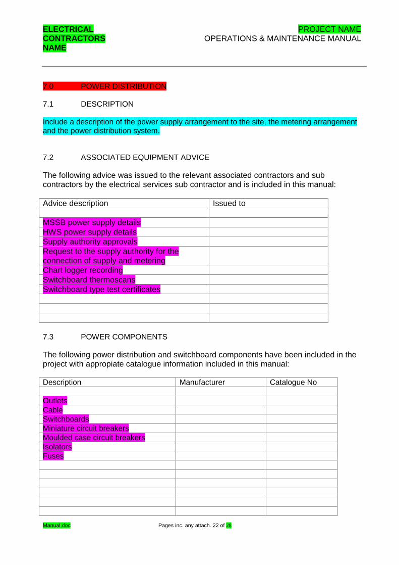
7.0 POWER DISTRIBUTION 7.1 DESCRIPTION Include a description of the power supply arrangement to the site, the metering arrangement and the power distribution system. 7.2 ASSOCIATED EQUIPMENT ADVICE The following advice was issued to the relevant associated contractors and sub contractors by the electrical services sub contractor and is included in this manual: Advice description Issued to MSSB power supply details HWS power supply details Supply authority approvals Request to the supply authority for the connection of supply and metering
Chart logger recording Switchboard thermoscans Switchboard type test certificates 7.3 POWER COMPONENTS The following power distribution and switchboard components have been included in the project with appropiate catalogue information included in this manual: Description Manufacturer Catalogue No Outlets Cable Switchboards Miniature circuit breakers Moulded case circuit breakers Isolators Fuses
ELECTRICAL PROJECT NAME CONTRACTORS OPERATIONS & MAINTENANCE MANUAL NAME
Manual.doc Pages inc. any attach. 23 of 28
7.4 SWITCHBOARD SCHEDULES The following power distribution board switchboard switch board schedules represent the switchboard circuit configuration at the time of practical completion and have been included in this manual: Distribution board DB-A DB-B DB-C

ELECTRICAL PROJECT NAME CONTRACTORS OPERATIONS & MAINTENANCE MANUAL NAME
Manual.doc Pages inc. any attach. 24 of 28
8.0 AS BUILT DRAWINGS The following as built drawings represent the electrical services installation as completed by the electrical services sub contract. The following as built drawings included in this manual are in hard copy as A3 and A1 sizes as well as on a Compact disc in AutoCAD R14 format. All information in the as built documents must be confirmed on site as these documents do not account for any changes or additions to the electrical services installation post practical completion of the electrical services sub contract. Number Title

ELECTRICAL PROJECT NAME CONTRACTORS OPERATIONS & MAINTENANCE MANUAL NAME
Manual.doc Pages inc. any attach. 25 of 28
9.0 EMERGENCY LIGHTING 9.1 REQUIREMENTS It is a legal requirement to test and rectify if required the emergency and exit lighting installation every six months to the requirements of the Australian standard AS2293. Emergency lighting is tested every six months by a simulated power outage. Results are to be recorded in a logbook or any approved system by the regulatory
authority. The logbook shall contain test results, corrective action taken, names of persons responsible for maintenance work and tests carried out and date of action.
Australian Standard 2293 Part 2, is the code which specifies requirements of testing and repairs of emergency lighting.
Replacement parts in servicing of emergency lighting must comply with the relevant Australian Standard and meet the manufacturer�s specification.
When replacing batteries in stand alone type luminaries (Single Point Unit), all cells must be replaced, and be the same type and ampere-hour rating.
9.2 PROCEDURE 9.2.1 Manual Test Individual Fitting The emergency lighting can be tested by pushing the red override button on each fitting. This function changes the supply from mains to battery power feeding the lamp. This test only checks that the lamp is operating. 9.2.2 Group Test Facility Emergency and Evacuation lighting test switches are located in the Main Switchboard, this tests all of the emergency and evacuation lighting in the installation. On pushing the test button a power outage is simulated, and power is removed to these circuits, for a predetermined time. This causes the emergency and evacuation lighting to operate, thereby lighting all emergence tubes/exit signs and evacuation lights. It is then a simple case of following the fitting identification numbers in the record book, referenced to a location on your drawings and check if the light is illuminated. The results are then recorded in the record book. Operation of the test circuit is on a timed basis, this is to overcome the problem of it is inadvertently left off. This however should be noted when testing large numbers of fittings, as they will turn off when the circuit times out if all lights are failing, check test circuit is still operating. On completion of testing record book and drawings are to be returned to their storage area, with a report sent to the principle, showing the condition of area tested and action required or instigated. Repair of fittings etc. will follow as arranged, with a test of the

ELECTRICAL PROJECT NAME CONTRACTORS OPERATIONS & MAINTENANCE MANUAL NAME
Manual.doc Pages inc. any attach. 26 of 28
individual fitting via the manual test method above, as proof of an effective repair (also to be documented in the appropriate record book). 9.3 LOG BOOK This manual includes a copy of an 8th edition GLS Emergency Lighting Maintenance Log Book And Manual. It is a statutory requirement this log book must be completed and updated with the test results of each test of the emergency and exit light installation.

ELECTRICAL PROJECT NAME CONTRACTORS OPERATIONS & MAINTENANCE MANUAL NAME
Manual.doc Pages inc. any attach. 27 of 28
10.0 TEST RESULTS The following tests have been undertaken and results included within this manual: Test Date Power distribution system Load balance results Switchboard thermoscans Lighting installation Communication installation Fire alarm installation Security installation MATV installation Lightning protection CCTV installation Background music installation School bell installation.

ELECTRICAL PROJECT NAME CONTRACTORS OPERATIONS & MAINTENANCE MANUAL NAME
Manual.doc Pages inc. any attach. 28 of 28
11.0 FIRE ALARM SYSTEM