PROJECT MANUAL VOLUME TWOAdmin/Finance+Admin+… · SECTION 00 00 01 3/27/2019 Page 1 of 1 City of...
523
CITY OF KIRKLAND KIRKLAND PARKS MAINTENANCE BUILDING RENOVATION PROJECT NO. 21-19-CMO Project 12006 120TH Pl. NE Kirkland, WA 98034 PROJECT MANUAL VOLUME TWO 3/27/2019
Transcript of PROJECT MANUAL VOLUME TWOAdmin/Finance+Admin+… · SECTION 00 00 01 3/27/2019 Page 1 of 1 City of...

CITY OF KIRKLAND KIRKLAND PARKS MAINTENANCE BUILDING
RENOVATION PROJECT NO. 21-19-CMO
Project 12006 120TH Pl. NE Kirkland, WA 98034
PROJECT MANUAL VOLUME TWO
3/27/2019

KIRKLAND PARKS MAINTENANCE BUILDING RENOVATION PROJECT DIRECTORY SECTION 00 00 01
3/27/2019 Page 1 of 1
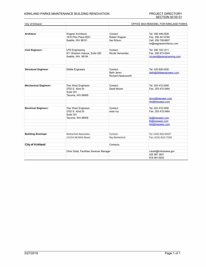
City of Kirkland OFFICE MAX REMODEL FOR KIRKLAND PARKS
Wagner Architects Contact: Tel: 206 448-25281916 Pike Place #221 Robert Wagner Fax: 206 441-6184Seattle, WA 98101 Ilva Wilson Cell: 206 728-8807
LPD Engineering Contact: Tel: 206 725-1211911 Western Avenue, Suite 420 Nicole Hernandez Fax: 206 973-5344Seattle, WA 98104 [email protected]
Dibble Engineers Contact: Tel: 425 828-4200Beth Jensn [email protected] Hawksworth
Tres West Engineers Contact: Tel: 253 472-33002702 S. 42nd St David Moore Fax: 253 472-3464Suite 301Tacoma, WA 98409
[email protected] [email protected]
Tres West Engineers Contact: Tel: 253 472-33002702 S. 42nd St sean roy Fax: 253 472-3464Suite 301Tacoma, WA 98409 [email protected]
[email protected] [email protected]
Wetherholt Associates Contact: Tel: (425) 822-839713104 NE 85th Street Ray Wetherholt Fax: (425) 822-7595
City of Kirkland Contacts:
Chris Dodd, Facilities Services Manager [email protected] 587 3931818 581-5933
Building Envelope
Architect:
Civil Engineer:
Structural Engineer
Mechanical Engineer:
Electrical Engineer:


KIRKLAND PARKS MAINTENANCE BUILDING RENOVATION TABLE OF CONTENTS SECTION 00 00 02
3/27/2019 Page 1 of 4
VOLUME ONE OF PROJECT MANUAL NUMBER TITLE PAGES DIVISION 0 - PROCUREMENT AND CONTRACTING REQUIREMENTS Title Page . . . . . . . . . . . . . . . . . . . . . . . . . . . . . . . . . . . . . . . . . . 1 00 00 01 Project Directory . . . . . . . . . . . . . . . . . . . . . . . . . . . . . . . . . . . . . 1 00 00 02 Table of Contents . . . . . . . . . . . . . . . . . . . . . . . . . . . . . . . . . . . . 4 00 00 10 Bidder’s Checklist. . . . . . . . . . . . . . . . . . . . . . . . . . . . . . . . . . . . . 2 00 10 10 Bid Advertisement. . . . . . . . . . . . . . . . . . . . . . . . . . . . . . . . . . . . .2 00 10 20 Bidder’s Qualifications . . . . . . . . . . . . . . . . . . . . . . . . . . . . . . . . . 2 00 15 30 Bidder Responsibility Criteria . . . . . . . . . . . . . . . . . . . . . . . . . . . .7 00 20 00 Instructions to Bidders . . . . . . . . . . . . . . . . . . . . . . . . . . . . . . . . . 5 00 30 00 Information Available to Bidders. . . . . . . . . . . . . . . . . . . . . . . . . . 1 00 41 00 Bid Form. . . . . . . . . . . . . . . . . . . . . . . . . . . . . . . . . . . . . . . . . . . . 4 00 43 30 Bid Security Form. . . . . . . . . . . . . . . . . . . . . . . . . . . . . . . . . . . . . 1 00 43 70 Non-Collusion Affidavit. . . . . . . . . . . . . . . . . . . . . . . . . . . . . . . . .1 00 44 00 Sub Contractor Listing. . . . . . . . . . . . . . . . . . . . . . . . . . . . . . . . . .1 00 45 70 Retainage Investment. . . . . . . . . . . . . . . . . . . . . . . . . . . . . . . . . . 2 00 52 20 Agreement Form. . . . . . . . . . . . . . . . . . . . . . . . . . . . . . . . . . . . . . 3 00 60 00 Bonds and Certificates. . . . . . . . . . . . . . . . . . . . . . . . . . . . . . . . . 3 00 62 30 Certificates of Insurance. . . . . . . . . . . . . . . . . . . . . . . . . . . . . . . . 1 00 65 19.16 Contractor’s Affidavit of Release of Liens Form. . . . . . . . . . . . . . 1 00 70 00 General Conditions. . . . . . . . . . . . . . . . . . . . . . . . . . . . . . . . . . . 45 00 80 00 Supplementary Conditions. . . . . . . . . . . . . . . . . . . . . . . . . . . …..1 00 82 50 Special Conditions. . . . . . . . . . . . . . . . . . . . . . . . . . . . . . . . . . . . 4 00 83 00 Department of Labor Wage Rates. . . . . . . . . . . . . . . . . . . . . . . . 1
DIVISION 1 - GENERAL REQUIREMENTS 01 11 00 Summary of Work. . . . . . . . . . . . . . . . . . . . . . . . . . . . . . . . . . . . .2 01 13 00 Schedule of Values . . . . . . . . . . . . . . . . . . . . . . . . . . . . . . . . . . . 2 01 16 00 Application for Payment. . . . . . . . . . . . . . . . . . . . . . . . . . . . . . . . 3 01 31 00 Coordination. . . . . . . . . . . . . . . . . . . . . . . . . . . . . . . . . . . . . . . . . 3 01 32 00 Project Meetings. . . . . . . . . . . . . . . . . . . . . . . . . . . . . . . . . . . . . . 2 01 33 00 Construction Schedule. . . . . . . . . . . . . . . . . . . . . . . . . . . . . . . . . 3 01 34 00 Submittals. . . . . . . . . . . . . . . . . . . . . . . . . . . . . . . . . . . . . . . . . . . 3 01 41 00 Product Requirements . . . . . . . . . . . . . . . . . . . . . . . . . . . . . . . . . 3 01 42 00 Substitution Request Form. . . . . . . . . . . . . . . . . . . . . . . . . . . . . . 3 01 43 00 Field Engineering. . . . . . . . . . . . . . . . . . . . . . . . . . . . . . . . . . . . . 2 01 51 00 Abbreviations. . . . . . . . . . . . . . . . . . . . . . . . . . . . . . . . . . . . . . . . 2 01 52 00 Inspections and Testing Services . . . . . . . . . . . . . . . . . . . . . . . . 3 01 53 00 Construction Facilities . . . . . . . . . . . . . . . . . . . . . . . . . . . . . . . . . 3 01 54 00 Tree and Plant Protection. . . . . . . . . . . . . . . . . . . . . . . . . . . . . . .3 01 55 00 Protection of Existing Conditions. . . . . . . . . . . . . . . . . . . . . . . . . 3 01 56 00 Temporary Erosion and Sediment Control . . . . . . . . . . . . . . . . . 1 01 56 26 Temporary Fencing . . . . . . . . . . . . . . . . . . . . . . . . . . . . . . . . . . . 1 01 80 10 Project Closeout. . . . . . . . . . . . . . . . . . . . . . . . . . . . . . . . . . . . . . 6 01 90 00 Project Record Documents. . . . . . . . . . . . . . . . . . . . . . . . . . . . . .2 DIVISION 2 EXISTING CONDITIONS 02 41 16 Building Demolition. . . . . . . . . . . . . . . . . . . . . . . . . . . . . . . . . . . 5 DIVISION 3 CONCRETE 03 30 00 Cast-In-Place-Concrete . . . . . . . . . . . . . . . . . . . . . . . . . . . . . . . 11 03 35 43 Polished Concrete Floors . . . . . . . . . . . . . . . . . . . . . . . . . . . . . .10
KIRKLAND PARKS MAINTENANCE BUILDING RENOVATION TABLE OF CONTENTS SECTION 00 00 02
3/27/2019 Page 2 of 4
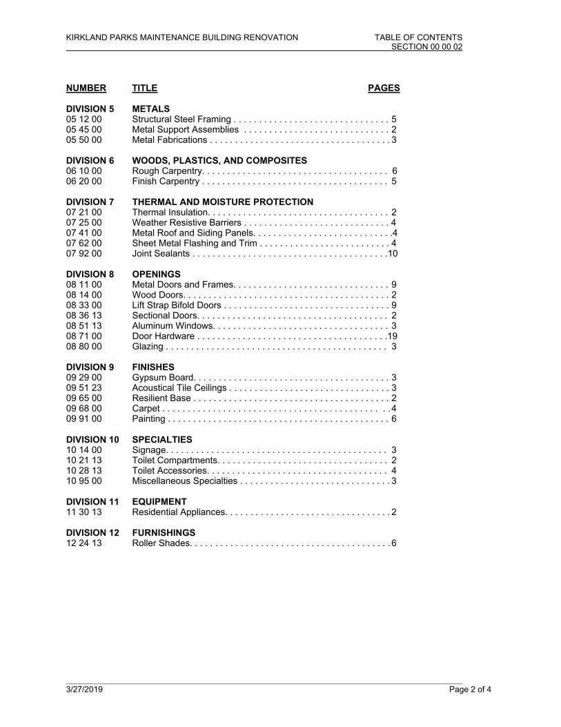
NUMBER TITLE PAGES DIVISION 5 METALS 05 12 00 Structural Steel Framing . . . . . . . . . . . . . . . . . . . . . . . . . . . . . . . 5 05 45 00 Metal Support Assemblies . . . . . . . . . . . . . . . . . . . . . . . . . . . . . 2 05 50 00 Metal Fabrications . . . . . . . . . . . . . . . . . . . . . . . . . . . . . . . . . . . . 3 DIVISION 6 WOODS, PLASTICS, AND COMPOSITES 06 10 00 Rough Carpentry. . . . . . . . . . . . . . . . . . . . . . . . . . . . . . . . . . . . . 6 06 20 00 Finish Carpentry . . . . . . . . . . . . . . . . . . . . . . . . . . . . . . . . . . . . . 5 DIVISION 7 THERMAL AND MOISTURE PROTECTION 07 21 00 Thermal Insulation. . . . . . . . . . . . . . . . . . . . . . . . . . . . . . . . . . . . 2 07 25 00 Weather Resistive Barriers . . . . . . . . . . . . . . . . . . . . . . . . . . . . . 4 07 41 00 Metal Roof and Siding Panels. . . . . . . . . . . . . . . . . . . . . . . . . . . .4 07 62 00 Sheet Metal Flashing and Trim . . . . . . . . . . . . . . . . . . . . . . . . . . 4 07 92 00 Joint Sealants . . . . . . . . . . . . . . . . . . . . . . . . . . . . . . . . . . . . . . .10 DIVISION 8 OPENINGS 08 11 00 Metal Doors and Frames. . . . . . . . . . . . . . . . . . . . . . . . . . . . . . . 9 08 14 00 Wood Doors. . . . . . . . . . . . . . . . . . . . . . . . . . . . . . . . . . . . . . . . . 2 08 33 00 Lift Strap Bifold Doors . . . . . . . . . . . . . . . . . . . . . . . . . . . . . . . . . 9 08 36 13 Sectional Doors. . . . . . . . . . . . . . . . . . . . . . . . . . . . . . . . . . . . . . 2 08 51 13 Aluminum Windows. . . . . . . . . . . . . . . . . . . . . . . . . . . . . . . . . . . 3 08 71 00 Door Hardware . . . . . . . . . . . . . . . . . . . . . . . . . . . . . . . . . . . . . .19 08 80 00 Glazing . . . . . . . . . . . . . . . . . . . . . . . . . . . . . . . . . . . . . . . . . . . . 3 DIVISION 9 FINISHES 09 29 00 Gypsum Board. . . . . . . . . . . . . . . . . . . . . . . . . . . . . . . . . . . . . . . 3 09 51 23 Acoustical Tile Ceilings . . . . . . . . . . . . . . . . . . . . . . . . . . . . . . . . 3 09 65 00 Resilient Base . . . . . . . . . . . . . . . . . . . . . . . . . . . . . . . . . . . . . . . 2 09 68 00 Carpet . . . . . . . . . . . . . . . . . . . . . . . . . . . . . . . . . . . . . . . . . . . . . 4 09 91 00 Painting . . . . . . . . . . . . . . . . . . . . . . . . . . . . . . . . . . . . . . . . . . . . 6 DIVISION 10 SPECIALTIES 10 14 00 Signage. . . . . . . . . . . . . . . . . . . . . . . . . . . . . . . . . . . . . . . . . . . . 3 10 21 13 Toilet Compartments. . . . . . . . . . . . . . . . . . . . . . . . . . . . . . . . . . 2 10 28 13 Toilet Accessories. . . . . . . . . . . . . . . . . . . . . . . . . . . . . . . . . . . . 4 10 95 00 Miscellaneous Specialties . . . . . . . . . . . . . . . . . . . . . . . . . . . . . . 3 DIVISION 11 EQUIPMENT 11 30 13 Residential Appliances. . . . . . . . . . . . . . . . . . . . . . . . . . . . . . . . . 2 DIVISION 12 FURNISHINGS 12 24 13 Roller Shades. . . . . . . . . . . . . . . . . . . . . . . . . . . . . . . . . . . . . . . . 6
KIRKLAND PARKS MAINTENANCE BUILDING RENOVATION TABLE OF CONTENTS SECTION 00 00 02
3/27/2019 Page 3 of 4
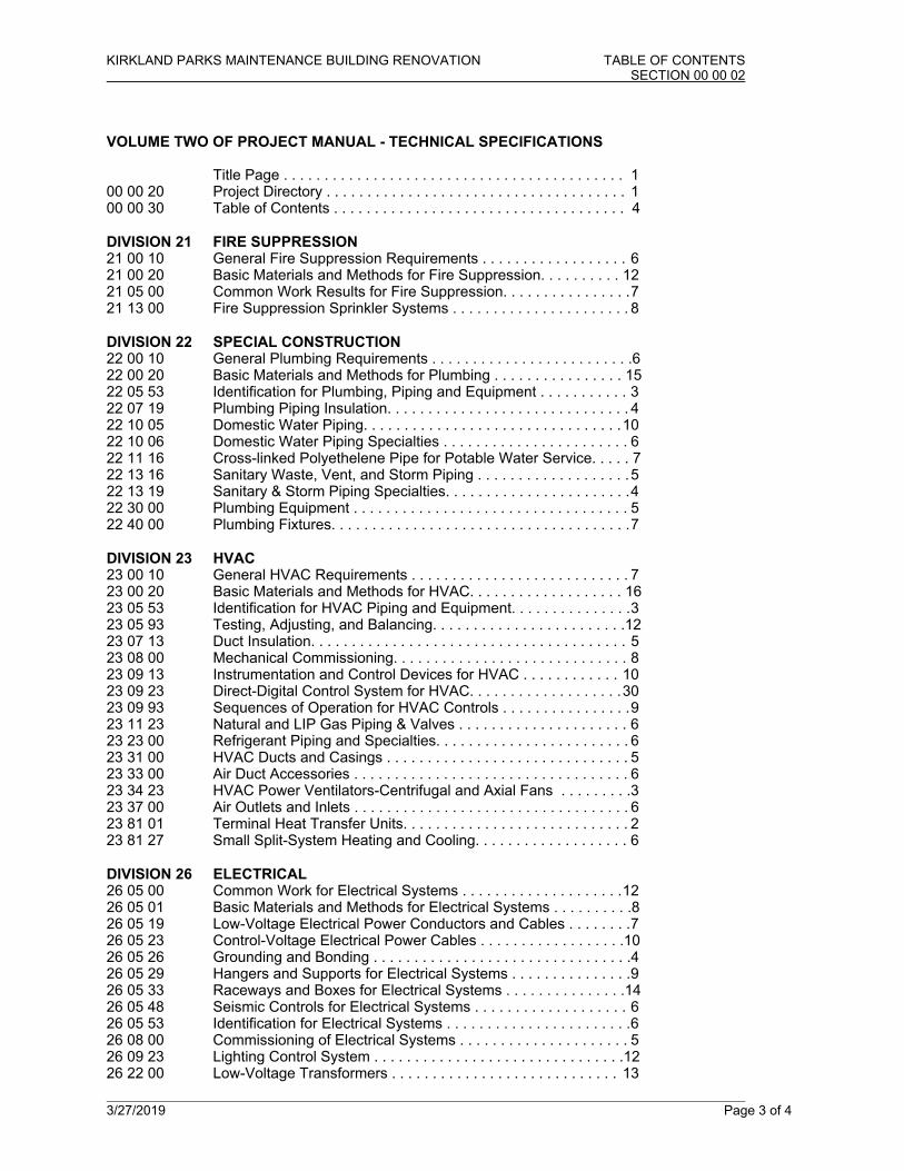
VOLUME TWO OF PROJECT MANUAL - TECHNICAL SPECIFICATIONS Title Page . . . . . . . . . . . . . . . . . . . . . . . . . . . . . . . . . . . . . . . . . . 1 00 00 20 Project Directory . . . . . . . . . . . . . . . . . . . . . . . . . . . . . . . . . . . . . 1 00 00 30 Table of Contents . . . . . . . . . . . . . . . . . . . . . . . . . . . . . . . . . . . . 4 DIVISION 21 FIRE SUPPRESSION 21 00 10 General Fire Suppression Requirements . . . . . . . . . . . . . . . . . . 6 21 00 20 Basic Materials and Methods for Fire Suppression. . . . . . . . . . 12 21 05 00 Common Work Results for Fire Suppression. . . . . . . . . . . . . . . . 7 21 13 00 Fire Suppression Sprinkler Systems . . . . . . . . . . . . . . . . . . . . . . 8 DIVISION 22 SPECIAL CONSTRUCTION 22 00 10 General Plumbing Requirements . . . . . . . . . . . . . . . . . . . . . . . . .6 22 00 20 Basic Materials and Methods for Plumbing . . . . . . . . . . . . . . . . 15 22 05 53 Identification for Plumbing, Piping and Equipment . . . . . . . . . . . 3 22 07 19 Plumbing Piping Insulation. . . . . . . . . . . . . . . . . . . . . . . . . . . . . . 4 22 10 05 Domestic Water Piping. . . . . . . . . . . . . . . . . . . . . . . . . . . . . . . . 10 22 10 06 Domestic Water Piping Specialties . . . . . . . . . . . . . . . . . . . . . . . 6 22 11 16 Cross-linked Polyethelene Pipe for Potable Water Service. . . . . 7 22 13 16 Sanitary Waste, Vent, and Storm Piping . . . . . . . . . . . . . . . . . . . 5 22 13 19 Sanitary & Storm Piping Specialties. . . . . . . . . . . . . . . . . . . . . . . 4 22 30 00 Plumbing Equipment . . . . . . . . . . . . . . . . . . . . . . . . . . . . . . . . . . 5 22 40 00 Plumbing Fixtures. . . . . . . . . . . . . . . . . . . . . . . . . . . . . . . . . . . . . 7 DIVISION 23 HVAC 23 00 10 General HVAC Requirements . . . . . . . . . . . . . . . . . . . . . . . . . . . 7 23 00 20 Basic Materials and Methods for HVAC. . . . . . . . . . . . . . . . . . . 16 23 05 53 Identification for HVAC Piping and Equipment. . . . . . . . . . . . . . . 3 23 05 93 Testing, Adjusting, and Balancing. . . . . . . . . . . . . . . . . . . . . . . .12 23 07 13 Duct Insulation. . . . . . . . . . . . . . . . . . . . . . . . . . . . . . . . . . . . . . . 5 23 08 00 Mechanical Commissioning. . . . . . . . . . . . . . . . . . . . . . . . . . . . . 8 23 09 13 Instrumentation and Control Devices for HVAC . . . . . . . . . . . . 10 23 09 23 Direct-Digital Control System for HVAC. . . . . . . . . . . . . . . . . . . 30 23 09 93 Sequences of Operation for HVAC Controls . . . . . . . . . . . . . . . . 9 23 11 23 Natural and LIP Gas Piping & Valves . . . . . . . . . . . . . . . . . . . . . 6 23 23 00 Refrigerant Piping and Specialties. . . . . . . . . . . . . . . . . . . . . . . . 6 23 31 00 HVAC Ducts and Casings . . . . . . . . . . . . . . . . . . . . . . . . . . . . . . 5 23 33 00 Air Duct Accessories . . . . . . . . . . . . . . . . . . . . . . . . . . . . . . . . . . 6 23 34 23 HVAC Power Ventilators-Centrifugal and Axial Fans . . . . . . . . .3 23 37 00 Air Outlets and Inlets . . . . . . . . . . . . . . . . . . . . . . . . . . . . . . . . . . 6 23 81 01 Terminal Heat Transfer Units. . . . . . . . . . . . . . . . . . . . . . . . . . . . 2 23 81 27 Small Split-System Heating and Cooling. . . . . . . . . . . . . . . . . . . 6 DIVISION 26 ELECTRICAL 26 05 00 Common Work for Electrical Systems . . . . . . . . . . . . . . . . . . . . 12 26 05 01 Basic Materials and Methods for Electrical Systems . . . . . . . . . .8 26 05 19 Low-Voltage Electrical Power Conductors and Cables . . . . . . . . 7 26 05 23 Control-Voltage Electrical Power Cables . . . . . . . . . . . . . . . . . .10 26 05 26 Grounding and Bonding . . . . . . . . . . . . . . . . . . . . . . . . . . . . . . . .4 26 05 29 Hangers and Supports for Electrical Systems . . . . . . . . . . . . . . . 9 26 05 33 Raceways and Boxes for Electrical Systems . . . . . . . . . . . . . . .14 26 05 48 Seismic Controls for Electrical Systems . . . . . . . . . . . . . . . . . . . 6 26 05 53 Identification for Electrical Systems . . . . . . . . . . . . . . . . . . . . . . . 6 26 08 00 Commissioning of Electrical Systems . . . . . . . . . . . . . . . . . . . . . 5 26 09 23 Lighting Control System . . . . . . . . . . . . . . . . . . . . . . . . . . . . . . .12 26 22 00 Low-Voltage Transformers . . . . . . . . . . . . . . . . . . . . . . . . . . . . 13

KIRKLAND PARKS MAINTENANCE BUILDING RENOVATION TABLE OF CONTENTS SECTION 00 00 02
3/27/2019 Page 4 of 4
26 24 16 Panelboards . . . . . . . . . . . . . . . . . . . . . . . . . . . . . . . . . . . . . . . .13 26 27 17 Equipment Wiring. . . . . . . . . . . . . . . . . . . . . . . . . . . . . . . . . . . . . 3 26 27 26 Wiring Devices . . . . . . . . . . . . . . . . . . . . . . . . . . . . . . . . . . . . . . 11 26 28 13 Fuses . . . . . . . . . . . . . . . . . . . . . . . . . . . . . . . . . . . . . . . . . . . . . . 2 26 28 16 Enclosed Switches . . . . . . . . . . . . . . . . . . . . . . . . . . . . . . . . . . . .4 26 43 13 Surge Protective Devices (SPDs) . . . . . . . . . . . . . . . . . . . . . . . . 8 26 50 00 Lighting . . . . . . . . . . . . . . . . . . . . . . . . . . . . . . . . . . . . . . . . . . . . 9 DIVISION 27 COMMUNICATIONS 27 10 00 Telecommunications Systems . . . . . . . . . . . . . . . . . . . . . . . . . . . 5 DIVISION 28 ELECTRONIC SAFETY AND SECURITY 28 13 00 Access Control Systems . . . . . . . . . . . . . . . . . . . . . . . . . . . . . . . 9 28 16 00 Intrusion Detection . . . . . . . . . . . . . . . . . . . . . . . . . . . . . . . . . . . . 7 28 23 00 Video Surveillance . . . . . . . . . . . . . . . . . . . . . . . . . . . . . . . . . . . 23 28 31 00 Fire Detection and Alarm Systems . . . . . . . . . . . . . . . . . . . . . . 23 DIVISION 31 EARTHWORK 31 10 00 Site Preparation . . . . . . . . . . . . . . . . . . . . . . . . . . . . . . . . . . . . . 3 31 12 00 Earthwork . . . . . . . . . . . . . . . . . . . . . . . . . . . . . . . . . . . . . . . . . . 4 31 41 33 Trench Safety Systems. . . . . . . . . . . . . . . . . . . . . . . . . . . . . . . . .1 DIVISION 32 EXTERIOR IMPROVEMENTS 32 12 16 Asphalt Concrete Paving . . . . . . . . . . . . . . . . . . . . . . . . . . . . . . . 3 32 31 19 Decorative Metal Fences and Gates . . . . . . . . . . . . . . . . . . . . . . 3 DIVISION 33 UTILITIES 33 30 00 Sanitary Sewer. . . . . . . . . . . . . . . . . . . . . . . . . . . . . . . . . . . . . . . 3 DRAWINGS: PART OF CONTRACT DOCUMENTS (Bound Separately)
***END OF SECTION 00 00 30***

KIRKLAND PARKS GENERAL FIRE SUPPRESSION REQUIREMENTS MAINTENANCE BUILDING RENOVATION SECTION 21 00 10
3/27/19 PAGE 1 OF 6
PART l - GENERAL
1.01 GENERAL
A. Conform to General Conditions, Supplementary Conditions, and Division 01.
B. This section of the specification applies to the entire mechanical work, both interior and
exterior, as specified herein after and shown on the plans.
C. This Contractor is responsible for coordination with all other trades.
1.02 SCOPE
A. All services to within five (5) feet of the building, shall be provided as shown on plans,
and final connections to these services shall be made by the Mechanical Contractor.
1.03 DEFINITIONS
A. The term "approved equal" means final approval by the Owner's representative of a
material or piece of equipment substituted for that which is shown in the specifications or
plans.
B. The term "provide" means the furnishing and installing of equipment (including
connections and appurtenances) complete and ready for use.
C. The terms "Mechanical Contractor (MC)" and "Electrical Contractor (EC)" as used in
these Specifications or on the Contract Drawings, refers to those subcontractors working
under the direction of the "General Contractor (GC)."
1.04 INTENT OF DRAWINGS
A. The drawings are diagrammatic and do not show the exact details and locations, nor all
offsets in piping. Contractor shall provide additional fittings, offsets and extensions in
piping and related mechanical insulation as required to meet the intent of the documents,
and shall include these items in his bid. Contractor shall also include in his bid provisions
to relocate or shift piping where conflicts exist with Structural, Architectural, or Electrical
components.
B. Refer to the complete set of Architectural, Structural, Electrical, and Civil Plans and
Specifications for additional details of the work. Review Plans and Specifications of other
trades to identify other requirements. Discrepancies shall be reported to the Owner's
representative immediately before ordering material or beginning work.
1.05 COORDINATION
A. Examine the Architectural, Civil, Structural and Electrical drawings before work is started.
Consult with each of the other Contractors regarding locations and spaces required for
work and lay out work to avoid interference. Maximum clearance shall be maintained for
service access and maintenance of all equipment. Failure to coordinate shall be
justification to require Contractor, at his own expense, to move his work to provide the
necessary space for the other contractors.
B. Mechanical systems have space priority as follows, listed with highest priority first:
Graded Drainage Piping, then Ductwork, Drainage Vents, Hydronic Piping, Domestic
Water Piping, Natural Gas Piping, and Fire Protection Piping. MC to make certain that
priority access is maintained. This shall be coordinated by the GC and MC without
assistance from Owner's representative, Engineer, or Architect.
C. Contractor shall be responsible for his own coordination between all other trades.
Development of Shop Drawings shall be a collaborative effort between the General
Contractor, Mechanical Contractor, Electrical Contractor and all other subcontractors

KIRKLAND PARKS GENERAL FIRE SUPPRESSION REQUIREMENTS MAINTENANCE BUILDING RENOVATION SECTION 21 00 10
3/27/19 PAGE 2 OF 6
working on the project. Shifting of piping, ductwork and other mechanical items shall be
the responsibility of the Team to maintain the intent of the documents. Submit shop
drawings to the Owner's representative.
1.06 WORK IN OTHER SECTIONS
A. Drawings and General Provisions of the Contract, including General and Special
Conditions and Division 01 Specification Sections, apply to this Section.
1.07 CODES AND REFERENCES
A. Codes and Standards listed shall be the most current issue as adopted by the Local
Jurisdiction. In the event of a conflict of codes, the most stringent code will apply.
1. International Building Code (IBC)
2. Uniform Plumbing Code (UPC)
3. International Mechanical Code (IMC)
4. Washington State Energy Code
5. SMACNA Duct Construction Standards, Metal and Flexible
6. National Electrical Code (NEC)
1.08 PERMITS AND FEES
A. Obtain and pay for all permits, licenses and construction or utility fees. Furnish final
certificate to Owner showing compliance with code requirements.
1.09 SCHEDULING
A. Comply with requirements of General Specifications.
1.10 PRIOR APPROVALS
A. Specifications have been written around equipment and material selected for this project
based on quality, size, capacity, and performance required to meet building design
criteria. Any equipment and/or material used in this project that is not as specified, must
have prior approval from the Owner's representative.
B. Request for Approval must be submitted with substitution request form included in
Division 0 to Owner's representative a minimum of 10 calendar days prior to bid date.
This letter shall be accompanied with complete information regarding items to be
substituted. If supplier requires a reply to the request for approval, he is to send a self-
addressed, stamped envelope with request.
C. Those items that receive prior approval will be listed in the Mechanical Addenda.
D. Supplier and/or Mechanical Contractor shall be responsible for ensuring that substituted
material or equipment is of the same size, quality, capacity, weight, and electrical
characteristics as that specified. Any changes and costs required during construction,
due to contractor's/supplier's neglect to properly select substituted equipment, shall be
paid by the contractor/supplier.
E. Prior approval to bid does not mean automatic final approval of material or equipment by
the Owner's representative. Final approval will be given after final submittal data has
been presented to Owner's representative, with complete information regarding weights,
capacities, size, electrical requirements and quality.
1.11 MATERIAL AND MATERIAL SUBMITTALS

KIRKLAND PARKS GENERAL FIRE SUPPRESSION REQUIREMENTS MAINTENANCE BUILDING RENOVATION SECTION 21 00 10
3/27/19 PAGE 3 OF 6
A. All material used on the project shall be new material and free from defects. This
Contractor shall submit catalog data and engineering data on all equipment as specified
or having received prior approval.
B. Material and equipment specified is designated by various manufacturer's catalog
numbers. Acceptable alternate manufacturers are also listed. Such manufacturers are
exempt from the 10-day prior approval clause of these specifications, but must submit
standard submittal data for final approval as otherwise noted.
C. Submittal shall be arranged in numerical order, according to specification section number
and item number. Submittal shall be bound in hard cover, loose-leaf binder(s).
D. Submittal shall be as follows: Before ordering or installing any of the materials, this
Contractor shall submit copies of complete information on the materials to be used on the
project. Submittal may be electronic or in hard copy. If contractor chooses to submit
printed copies, he shall provide five copies to the Owner’s representative. Submittal shall
include, but not be limited to, the following.
1. Contractor's Cost Breakdown.
2. Complete List of Subcontractors and Suppliers.
3. Pipe, Valves and Specialties for fire protection systems.
4. Fire Sprinkling Systems.
5. Fire pumps.
6. Insulation.
E. The Owner's representative will return one set, electronic or printed copy, of this submittal
to the contractor showing any corrections, additions, and/or deletions. If the Contractor
needs additional printed copies, he shall photocopy his approved copy of the required
items. This Contractor shall resubmit those items that need to be corrected or added.
1.12 CONTRACTOR'S COST BREAKDOWN
A. Mechanical Contractor shall submit, with the bound submittals, a cost breakdown of the
major portions of his work, pursuant to the following outline.
1. Job organization and submittals.
2. Outside site utilities.
3. Fire protection systems.
1.13 RECORD DRAWINGS, OPERATING INSTRUCTIONS, OPERATION AND MAINTENANCE
RECORD (AS-BUILT) DRAWINGS
A. This Contractor shall maintain a set of Contract Drawings at the site on which the actual
installed location of piping, equipment, etc., shall be shown in a legible, neat manner.
This set of plans shall show actual dimensions (including depth of bury) of underground
piping from construction lines, so they can be readily found after covering. Upon
completion of the project, the as-built information shall be transformed into AutoCAD
version 2010 or greater. Record drawings shall be the same size as contract drawings.
This set of plans shall be submitted for final approval. Drawings shall be one full size set,
one half size set and on CD in PDF and .dwg format. The contractor shall be ready for
review of the on-site as-builts monthly prior to submitting his billing. Failure to have
drawings available for review may delay monthly billings.
1.14 OPERATING INSTRUCTIONS

KIRKLAND PARKS GENERAL FIRE SUPPRESSION REQUIREMENTS MAINTENANCE BUILDING RENOVATION SECTION 21 00 10
3/27/19 PAGE 4 OF 6
A. Operate all systems through complete cycles in the presence of designated Owner's
representative. Give instructions for operation, care and maintenance. All systems shall
be operated through complete operating cycles for a minimum period of 7 days in
conjunction with the designated Owner's representative before acceptance.
1.15 TRAINING
A. The Mechanical Contractor shall digitally record all Owner Mechanical training sessions
and shall provide copies on DVDs. Training sessions shall be provided for all mechanical
systems. Three copies of these DVDs shall be turned over to the Owner at the
completion of the project.
1.16 OPERATION AND MAINTENANCE MANUALS (O&Ms)
A. General: Provide one preliminary bound set of Operation and Maintenance Manuals
including maintenance information and parts list furnished by the manufacturer with the
equipment, together with supplementary drawings where necessary, to itemize serving
and maintenance points. Include the Valve Tag list(s) as posted in the Mechanical
spaces. Include filter maintenance, methods of operation, seasonal requirements,
manufacturer's data and warranty forms. Warranty forms are to be located in the front of
the manuals as well as in each applicable section. Provide address and 24-hour phone
number of the firms responsible under warranty. Items requiring service or correction
during the warranty period shall be serviced within 24-hours of notification by Owner.
Data in manuals shall be neat, clean copies, posted on 8 1/2" x 11" sheets, with
operation and maintenance instructions for each item of equipment installed. Drawings
shall be accordion folded. An index shall be provided with all contents listed in an orderly
presentation according to specification section.
B. Number of Copies: A preliminary set of the O&M Manuals shall be submitted for
approval. After this set has been approved, two additional sets shall be prepared and the
three sets shall be transmitted to the Owner's representative.
C. Binding: Organize operating and maintenance data into suitable sets of manageable size.
Copies shall be submitted in 3-ring binders. Covers shall include the name of the Job,
Owner, Architect, Engineer, Contractor, and the year of completion. The back edge of the
binder shall include a label with the name of the Job, the Owner and the year completed.
Each copy shall have a typewritten index and tabbed dividers between equipment
categories. Binders to be no more than 80% full.
1.17 CERTIFICATIONS
A. Provide written certification that work has been fully completed in strict accordance with
Plans and Specifications and request final inspection.
B. Provide written certification that Contractor will replace materials and workmanship that
prove defective for one (1) year after date of acceptance or extended warranty as listed in
individual sections.
C. Provide written certification of inspection from the Authority Having Jurisdiction, stating
that all work has been inspected, accepted, and approved as complying with existing
governing ordinances and codes.
D. Provide written certification that Owner's representative has been fully instructed in the
operation and function of all mechanical systems.
E. Provide copies of certifications in the O & M Manuals.
1.18 DOCUMENTS
KIRKLAND PARKS GENERAL FIRE SUPPRESSION REQUIREMENTS MAINTENANCE BUILDING RENOVATION SECTION 21 00 10
3/27/19 PAGE 5 OF 6
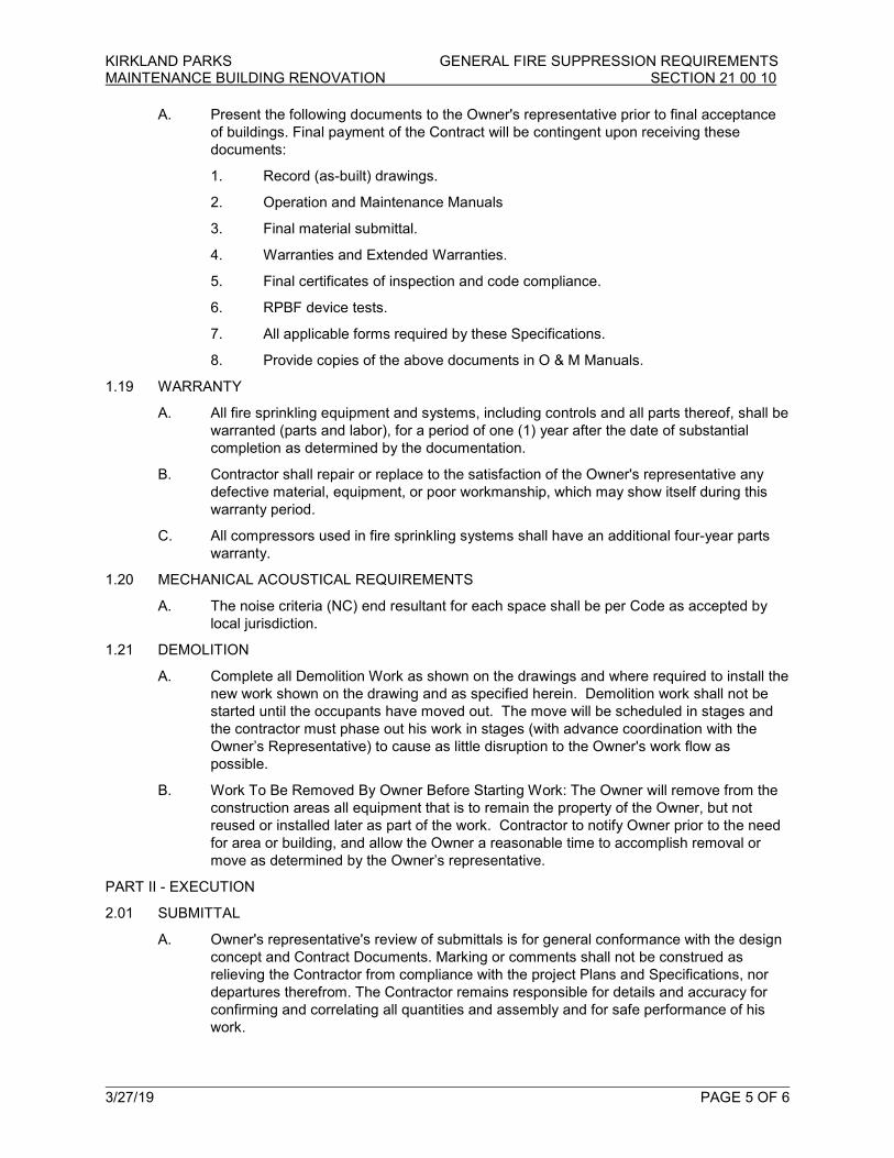
A. Present the following documents to the Owner's representative prior to final acceptance
of buildings. Final payment of the Contract will be contingent upon receiving these
documents:
1. Record (as-built) drawings.
2. Operation and Maintenance Manuals
3. Final material submittal.
4. Warranties and Extended Warranties.
5. Final certificates of inspection and code compliance.
6. RPBF device tests.
7. All applicable forms required by these Specifications.
8. Provide copies of the above documents in O & M Manuals.
1.19 WARRANTY
A. All fire sprinkling equipment and systems, including controls and all parts thereof, shall be
warranted (parts and labor), for a period of one (1) year after the date of substantial
completion as determined by the documentation.
B. Contractor shall repair or replace to the satisfaction of the Owner's representative any
defective material, equipment, or poor workmanship, which may show itself during this
warranty period.
C. All compressors used in fire sprinkling systems shall have an additional four-year parts
warranty.
1.20 MECHANICAL ACOUSTICAL REQUIREMENTS
A. The noise criteria (NC) end resultant for each space shall be per Code as accepted by
local jurisdiction.
1.21 DEMOLITION
A. Complete all Demolition Work as shown on the drawings and where required to install the
new work shown on the drawing and as specified herein. Demolition work shall not be
started until the occupants have moved out. The move will be scheduled in stages and
the contractor must phase out his work in stages (with advance coordination with the
Owner’s Representative) to cause as little disruption to the Owner's work flow as
possible.
B. Work To Be Removed By Owner Before Starting Work: The Owner will remove from the
construction areas all equipment that is to remain the property of the Owner, but not
reused or installed later as part of the work. Contractor to notify Owner prior to the need
for area or building, and allow the Owner a reasonable time to accomplish removal or
move as determined by the Owner’s representative.
PART II - EXECUTION
2.01 SUBMITTAL
A. Owner's representative's review of submittals is for general conformance with the design
concept and Contract Documents. Marking or comments shall not be construed as
relieving the Contractor from compliance with the project Plans and Specifications, nor
departures therefrom. The Contractor remains responsible for details and accuracy for
confirming and correlating all quantities and assembly and for safe performance of his
work.

KIRKLAND PARKS GENERAL FIRE SUPPRESSION REQUIREMENTS MAINTENANCE BUILDING RENOVATION SECTION 21 00 10
3/27/19 PAGE 6 OF 6
2.02 DEMOLITION
A. Complete all demolition, wrecking, and removal of work necessary for the completion of
the work shown on the drawings and/or as specified. All mechanical materials
designated for removal shall be removed from site and disposed of legally. The Owner
shall be offered the right of first refusal for demolished mechanical equipment and
components. Loading and disposal as described here shall be at no expense to the
Owner. Care shall be taken in making openings in walls and roofs as not to damage any
of the existing walls, floors and roofs. Where holes are left from removal of mechanical
equipment this Contractor shall be responsible for patching same to match the
surrounding finishes unless otherwise shown or specified.
B. Debris: Allow no debris to accumulate at, or in buildings, on grounds, streets, and/or
walks. Haul away from site as soon as removed. Allow no debris to remain in the
building and/or outside the building overnight. Legally dispose of at Contractor's
expense.
C. Interior Dust Control: Provide dust tight partition around area to be cut and as required to
prevent dust from entering the ventilation system. Equip partition with adequate access
doors that can be closed dust tight while cutting work is in progress. Remove dust tight
partitions when no longer required.
D. Building Protection: Protect the inside of the building from foul weather by covering wall
and roof openings.
E. Asbestos Materials: Notify the Owner’s representative if the presence of asbestos is
suspected. Immediately stop work in that area.
F. Refrigeration Recovery: The recovery of all refrigerant from existing equipment shall
conform to accepted industry standards and methods and shall be in compliance with all
applicable regulations. Refrigerant shall not be vented to atmosphere.
G. Structural Members: Check with, and gain approval from, the Owner’s representative
prior to cutting or altering structural members.
***** END OF SECTION 21 00 10*****

KIRKLAND PARKS BASIC MATERIAL AND METHODS FOR FIRE SUPPRESSION MAINTENANCE BUILDING RENOVATION SECTION 21 00 20
3/27/19 PAGE 1 OF 12
PART l - GENERAL
1.01 WORK INCLUDES
A. General requirements for basic materials and methods.
B. At a minimum, provide system per requirements of NFPA 13. Provide additional items as
noted in these specifications. In the event that information in these specifications conflicts
with NFPA 13, the more stringent requirements shall apply.
1.02 REFERENCES
A. American Society of Heating, Refrigeration and Air Conditioning Engineers (ASHRAE).
B. "Seismic Restraint Manual Guidelines for Mechanical Systems" by Sheet Metal and Air
Conditioning Contractors National Association, Inc. (SMACNA).
C. Sprinkler line attachments shall conform to NFPA Pamphlet 13. See Fire Protection
Specifications.
PART ll - PRODUCTS
2.01 GENERAL
A. See specific sections for this requirement.
2.02 PRODUCT TESTING
A. Any piece of equipment used in this project and hereinafter specified which, by its nature,
requires electrical connection, such as compressors, pumps, etc., must be provided with
an approval label from one of the agencies hereinafter listed.
B. Approval from agency must be for the total package; approval of individual components
not acceptable. Labels must be located outside of equipment and shall be visible to
inspector. Comply with all requirements of RCW 19.28.010 and NEC Sections 90-7 and
110-3 (1993).
C. It shall be the responsibility of this Contractor or the equipment supplier to meet the
requirements of this section. Any agency costs to provide appropriate label for a piece of
equipment must be included in this bid. Failure by this Contractor or supplier to obtain
approval labels prior to bid shall be sufficient cause for this Contractor/supplier to obtain
all such labels at no additional cost to Owner. The following is a list of approval testing
laboratories:
1. Underwriters Laboratories, Inc., www.ul.com
2. Canadian Standards Association, www.csagroup.org
3. American Gas Association, www.aga.org.
4. Factory Mutual Systems, www.fmglobal.com
5. MET Electrical Testing, www.metlabs.com
6. Intertek Testing, www.intertek.com
2.03 DAMAGED OR REJECTED MATERIALS
A. Remove from the site immediately.
2.04 STARTERS AND DISCONNECTS
KIRKLAND PARKS BASIC MATERIAL AND METHODS FOR FIRE SUPPRESSION MAINTENANCE BUILDING RENOVATION SECTION 21 00 20
3/27/19 PAGE 2 OF 12
A. All starters shall be provided and installed by Electrical Contractor unless otherwise
noted.
B. All disconnects shall be provided and installed by Electrical Contractor unless otherwise
noted.
C. This Contractor shall coordinate with the Electrical Contractor and provide voltage,
phase, horsepower, and amperage, based on approved submittals and the actual
equipment being provided.
2.05 FIRE INTEGRITY - PENETRATION SEALING SYSTEMS
A. Manufacturers
1. 3M Fire Products
2. Holdrite
3. Approved equal
B. The penetration sealing systems shall be provided with F-Rating and/or T-Rating as
required by IBC Section 714.3 and 714.4. Penetrations include the following:
1. Through-penetration firestopping in fire-rated construction.
2. Construction-gap firestopping at connections of the same or different materials in
fire-rated construction.
3. Construction-gap firestopping occurring within fire-walls, floor or floor-ceiling
assemblies.
4. Construction-gap firestopping in smoke partitions.
5. Through-penetration smoke stopping in smoke partitions.
6. Construction-gap smoke stopping in smoke partitions.
7. All piping penetrating mechanical spaces, mechanical mezzanines, mechanical
lofts, mechanical boiler rooms, or other mechanical spaces, shall be fire caulked,
even if the walls are not rated. Visible piping penetrations shall be covered by
split chrome-plated floor and ceiling plates.
C. All products shall be listed in Underwriters Laboratory Fire Resistance Directory.
Firestopping for penetrations and voids shall be UL-tested systems
1. Through-penetration firestop devices (XHCR).
2. Fire resistance ratings (BXUV).
3. Through-penetration firestop systems (XHEZ).
4. Fill, void or cavity material (XHHW).
D. All material shall be tested per American Society for Testing and Material Standards,
ASTM E814: Standard test method for fire tests of through-penetration firestops.
E. Firestopping for penetrations and voids shall be UL-tested systems.
2.06 HANGERS
A. Manufacturers
1. Grinnell
2. Michigan Hanger

KIRKLAND PARKS BASIC MATERIAL AND METHODS FOR FIRE SUPPRESSION MAINTENANCE BUILDING RENOVATION SECTION 21 00 20
3/27/19 PAGE 3 OF 12
3. Tolco
4. PHD
5. Anvil
6. Holdrite
7. Approved equal
B. Provide all anchors, hangers and all supports for piping and equipment included in
contract.
C. It is the responsibility of the Contractor to provide an adequate pipe suspension system in
accordance with recognized engineering practices, using standard, commercially-
accepted pipe hangers and accessories.
D. All pipe hangers and supports shall conform to the latest requirements of ASME B31.1
Code for Pressure Piping, and Manufacturers Standardization Society Documents MSS
SP-58 and MSS SP-69.
2.07 INSERTS AT HANGERS AND SUPPORTS
2.08 ELECTRIC MOTORS
A. Minimum efficiencies of electric motors shall comply with the Washington State Energy
Code.
2.09 ACCESS DOORS AND PANELS
A. Manufacturers:
1. Jay R. Smith
2. Milcor
3. Mifab
4. Approved equal.
B. 16 gauge steel door and frame with concealed hinge and cylinder lock. Provide matching
latches/locks keyed the same for multiple panels in a project. When "B" dimension is 24"
or more, provide additional latches at the top and bottom of door. Provide finish and
material as noted in Part 3 – Execution.
2.13 VIBRATION AND SEISMIC CONTROLS
A. Manufacturers:
1. Kinetics Noise Control, Inc.
2. Mason Industries
3. Amber-Booth
4. I.S.A.T.
5. Flexicraft
6. Twin City Hose
7. Approved equal.
B. General

KIRKLAND PARKS BASIC MATERIAL AND METHODS FOR FIRE SUPPRESSION MAINTENANCE BUILDING RENOVATION SECTION 21 00 20
3/27/19 PAGE 4 OF 12
1. If equipment is internally isolated by the manufacturer, internal isolation (base
and isolator) shall be equivalent to the scheduled base and isolator and the
isolator shall meet the scheduled spring static deflection.
2. Size anchoring bolts to withstand lateral seismic shear and isolate bolts from
direct contact with structure using bolt isolation washer and bushing.
3. Bases specified in the schedule can be supplied by the manufacturer of the
equipment if they meet the specification given herein.
4. Electrical connections shall be made with floppy length of flexible cable.
5. Piping in connected to vibrating equipment shall be supported from resilient
ceiling hangers or from floor mounted resilient supports.
C. Piping not requiring sway bracing is as follows:
1. Piping in mechanical spaces less than 1".
2. All other piping less than 2-1/2".
3. Piping suspended by hangers 12" or less in length measured from the top of the
pipe to bottom of hanger support where the hanger is attached.
PART lll - EXECUTION
3.01 LAYING OUT WORK
A. Locate all general reference points as established by the General Contractor and take
such action as is necessary to prevent their destruction; lay out work and be responsible
for all lines, elevations, grading for utilities and other work executed under the Contract.
Exercise proper precautions to verify figures shown on drawings, before laying out work
and be responsible for any errors resulting from failure to exercise such precaution. The
coordination of the utility installation with the final site grading and elevation by the
General Contractor shall be the responsibility of this contractor. Locate existing utility
lines which will be affected by the building location before any footing work begins.
Report conflicts with the Plans to the Owner's representative for adjustment before
proceeding with the work. Failure to follow this instruction will result in the contractor
being required to alter his work at his own expense.
3.02 ELECTRICAL WORK
A. All electrical work performed under this Section of the Specification shall conform to all
applicable portions of the Electrical Section of the Specifications, and shall conform to all
applicable codes.
3.03 WORKMANSHIP
A. Furnish and install all equipment for a neat and finished appearance. If it is the opinion of
the Owner's representative that any portion of the work has not been installed in a
workmanlike manner, or has been left in a rough unfinished manner, Contractor will be
required to remove and reinstall the equipment, and patch and paint surrounding
surfaces in a manner satisfactory to the Owner's representative. This shall be completed
without any increase in cost to the Owner.
3.04 EXCAVATION - GENERAL
A. Perform all necessary excavation, shoring and backfilling required for the proper
installation of work inside the buildings and premises, or outside as may be necessary.
Slope sides of excavation to comply with local codes and ordinances having jurisdiction.

KIRKLAND PARKS BASIC MATERIAL AND METHODS FOR FIRE SUPPRESSION MAINTENANCE BUILDING RENOVATION SECTION 21 00 20
3/27/19 PAGE 5 OF 12
Shore and brace where sloping is not possible because of space restrictions or stability of
material excavated.
B. Excess excavation shall be backfilled with gravel or sand and mechanically compacted to
give full support to the piping. No underground lines shall be covered until the installation
has been approved by the Owner's representative, and the local Authority Having
Jurisdiction. Maintain sides and slopes of excavations in safe condition until completion of
backfilling. All backfill shall be thoroughly compacted.
C. No cinders shall be used for backfilling where steel, iron or copper piping is used. All
trenches near or under footings shall be cut only after approval of the Owner's
representative, and all backfilling of such trenches shall be according to his direction.
D. All items of grading which will in any manner affect the bearing capacity of the soil
foundations upon which will be placed floor slabs, walls, column footings or pipe beds
shall be performed to the satisfaction of the Owner's representative. All soil foundation
areas which will in any manner support any of the above-stated construction will be
compacted by the use of mechanical tampers to at least 95% of the maximum density of
the soil foundations as determined by the compaction control test, in accordance with the
"Method of test for Moisture Density Relations of Soils, ASTM Designation D1557." The
moisture control at the time of compaction shall be uniform throughout the area and shall
not vary more than 5% above or below the optimum moisture content as determined by
the above described "Compaction Control Test." Place fill in 8" loose layers, each layer
compacted.
3.05 EXCAVATION DEWATERING
A. Prevent surface water and subsurface or ground water from flowing into excavations, and
from a flooding project site and/or surrounding area.
B. Do not allow water to accumulate in excavations. Remove water to prevent softening of
foundation bottoms, undercutting footings, and soil changes detrimental to stability of
subgrades and foundations. Provide and maintain pumps, well points, sumps, suction
and discharge lines, and other dewatering system components necessary to convey
water away from excavations.
C. Establish and maintain temporary drainage ditches and other diversions, outside
excavation limits to convey rain water and water removed from excavations to collection
points or run off areas. Do not use trench excavation as temporary drainage ditches.
3.06 EXCESS EXCAVATION MATERIAL
A. Dirt and debris from trench excavation shall be disposed of by this Contractor, as directed
by the Owner's representative.
3.07 PIPING INSTALLATION
A. Lay piping in straight lines with uniform slope, leave no pockets. Care shall be taken to
keep all foreign materials out of the piping during installation. Where ground water is
present, provide suction pumps to keep trenches free of water, and cap ends of piping
exposed to ground water when work is interrupted.
B. All underground piping used for the distribution of fire protection services located outside
the building perimeter shall be buried a minimum of 36" from finish grade to top of piping.
C. All piping run above the floor SHALL NOT BE LOCATED OVER ELECTRICAL PANELS
OR SWITCHBOARDS, except where located above a structural ceiling, or with drain
pans approved by the AHJ. Piping includes, but is not limited to, fire sprinkler lines.

KIRKLAND PARKS BASIC MATERIAL AND METHODS FOR FIRE SUPPRESSION MAINTENANCE BUILDING RENOVATION SECTION 21 00 20
3/27/19 PAGE 6 OF 12
D. All piping SHALL BE ROUTED AROUND Elevator Equipment Rooms. Piping may serve
the room, but shall not pass through it. Follow all codes applicable to these areas.
E. Provide access panels to valves located above hard ceilings.
3.08 OPENINGS IN PIPING
A. Keep all openings covered tightly with plastic during the work.
3.09 PIPE SLEEVES
A. General: Provide pipe sleeves for piping passing through foundations, walls, floors,
partitions, and roof to allow piping to pass freely through.
B. Foundation Walls: Where piping passes through walls below finished grade, but does not
enter the building spaces, the sleeves shall be Schedule 40 galvanized steel pipe.
Provide a modular seal between the sleeve and the piping.
C. Building Walls (Below Grade) and Floor Slabs: Where piping passes through building
walls below grade, and floor slabs on grade or below grade, the sleeves shall extend a
minimum of 1" inside the building wall or above the finished floor level, and shall be made
watertight and gas tight by the appropriate modular seal. Sleeves shall be Schedule 40
galvanized steel pipe. If the sleeve and modular seal are subject to trapping water on the
top side, pack with water-resistant foam and caulk with flexible caulking or grout.
D. Building Walls and Floor Slabs (Above Grade) - New Construction: Where piping passes
through concrete walls or floors within the building, the sleeves shall be of sufficient
strength to withstand the pressure and concrete pouring operation without deforming or
rupturing. Sheet metal ductwork with ends slit and formed into flanges is not acceptable.
Sleeves shall extend 1" above the finished floor. Sleeves in walls shall be flush on both
sides.
E. Building Walls (Above Grade) - Existing Construction: Where piping passes through
concrete or masonry walls, provide galvanized sheet metal sleeves. When piping passing
through is insulated, the sleeve shall be large enough to permit the covering to pass
through. Where the wall is a fire separation, the opening between the sleeve and
insulation shall be sealed with intumescent material; see Paragraph "Fire Integrity" in this
section. The wall around sleeves shall be patched to original finish.
3.10 WALL/FLOOR PLATES AND ESCUTCHEONS
A. Where piping passes through any wall, floor or ceiling, it shall be fitted with chromium-
plated escutcheons, with suitable set screws or other approved holding device. Where
extended sleeves are necessary, the plates shall be of sufficient depth to cover the
sleeves.
3.11 PIPE HANGERS AND SUPPORTS
A. Where thermal movement in the pipe line will occur, the pipe hanger assembly must be
capable of supporting the line in all operating conditions. Accurate weight balance
calculations shall be made to determine the supporting force at each hanger location, in
order to prevent excessive stress in either pipe or equipment connections.
B. Where piping is to be supported from building steel, beam clamps shall be used. Beam
clamp selection shall be for the required load and the configuration of the steel at the
point of attachment. Drilling holes in the steel for hanger rod will not be permitted unless
approved by the Structural Engineer. Use only adjustable side beam clamps (Type 25);
standard beam clamps are not acceptable.
KIRKLAND PARKS BASIC MATERIAL AND METHODS FOR FIRE SUPPRESSION MAINTENANCE BUILDING RENOVATION SECTION 21 00 20
3/27/19 PAGE 7 OF 12
C. Riser Clamps (Vertical Piping): Piping shall be supported at each floor with a riser clamp
or at sufficient intervals to carry the weight of the piping and that of its contents. Stacks
shall be supported at their base by a concrete pier or by a suitable hanger located on the
horizontal run, close to the riser. Riser clamp extensions shall rest on the building
structure where possible; auxiliary steel supports shall be provided where it is impractical
to rest directly on the building structure.
D. Angle Clips: Where piping is to be supported from building wood structure, angle clips
shall be used with lag bolts sized to support the load in shear. Any attachment to wooden
structural members shall be subject to the approval of the Structural Engineer.
E. Hanger Rods: Hanger rod size shall be selected on the basis of loading from the
following table:
3/8" 610 pounds
1/2" 1130 pounds
5/8" 1810 pounds
F. Hangers shall be subject to tensile loading only. Where lateral or axial movement is
anticipated, use suitable linkage in hanger rod to permit swing. DO NOT BEND RODS.
G. All rods shall be electro-plated to prevent corrosion.
H. All rods shall be double-nutted with lock washer and cut washer, on both ends if
applicable, and excess rod on the bottom shall be cut flush and ground for safety.
I. Hanger Spacing: The maximum allowable spacing for pipe hangers shall be in
accordance with the following. Where concentrated loads of valves, fittings, etc., occur,
closer spacing will be necessary and shall be based on the weight supported and
recommended loads for the hanger components.
1. Spacing:
a. Steel - Threaded or Welded:
1) Horizontally: 3/4" and smaller, 10'; 1" and larger, 12'.
2) Vertically: Every other floor, not to exceed 25'. See note 1.
b. Notes Referenced Above:
1) Vertical water lines may be supported in accordance with
recognized engineering principles with regard to expansion and
contraction when first approved by the Authority Having
Jurisdiction
2) See the appropriate IAPMO Installation Standard for expansion
and other special requirements.
J. Hangers - Horizontal Piping:
1. General: All hangers shall be provided with means of vertical adjustment. The
following schedule shall be followed to select acceptable hangers for the type of
service.
a. Steel Piping:
1) Adjustable Split Ring Swivel Hanger
2) Adjustable steel Band Hanger
3) Clevis Hanger
KIRKLAND PARKS BASIC MATERIAL AND METHODS FOR FIRE SUPPRESSION MAINTENANCE BUILDING RENOVATION SECTION 21 00 20
3/27/19 PAGE 8 OF 12
2. Trapeze Hangers: Where piping is grouped in parallel, provide manufactured
strut or trapeze hangers consisting of two steel angles bolted back-to-back, with
space between for a hanger rod at each end. Where the length of angles is
greater than 24", there shall be three (3) rod supports. Piping shall be able to
move independently, and hanger spacing shall be dictated by the smallest pipe.
3. Brackets and Racks: Where piping is run adjacent walls or steel columns, welded
steel brackets shall be used as base supports. Multiple pipe racks or trapeze
hangers shall be designed and fabricated to suit conditions.
4. Vibration Control: Provide a vibration control hanger for all piping within a
mechanical room and at the first three hanger locations from any motor operated
equipment. Hanger shall consist of steel frame and spring, with neoprene
washers.
5. Anchors, Guides and Sliding Supports: Shall be as shown on the drawings or as
necessary to prevent excessive stress in either piping or equipment.
6. Auxiliary Steel: All auxiliary steel necessary for the installation of the pipe
hangers and supports shall be designed in accordance with the AISC Steel
Handbook, furnished by the Contractor, and shall receive one shop coat of
primer paint.
7. Submittals: The Contractor shall submit the following information and data for
approval prior to installation.
a. Data Sheets on all cataloged items to be used.
b. Sketches covering all specially designed hanger assemblies and
fabrications.
3.12 CUTTING AND PATCHING (NEW WORK)
A. Furnish dimensions and locations of openings to other Contractors doing the work.
Provide ample time to avoid delays and unnecessary labor. Cutting and patching made
necessary to admit work, repair defective material or workmanship, or by neglect to
anticipate proper requirements, shall be done by the General Contractor. at the expense
of this contractor.
3.13 CUTTING AND PATCHING (EXISTING STRUCTURE)
A. All necessary cutting and patching of existing structures necessary for installation of fire
sprinkler work shall be done by this contractor, as directed by the Owner's representative.
B. All surfaces must be patched upon completion of the work to the satisfaction of the
Owner's representative. Final finish of all patched surfaces shall be done per
Architectural finish schedule, by the General Contractor. All excavation necessary for this
contractor shall be performed by the this contractor. Surfaces shall be patched as
hereinbefore specified and all backfilling shall be done in accordance with requirements
of this section and other related notes in the Contract Documents. If none specified,
restore to original condition.
3.14 ACCESSIBILITY
A. Locate valves, etc., so as to be easily accessible in mechanical spaces or through access
panels, specified hereinafter. Otherwise, obtain Owner's representative's approval of
location.
B. Any equipment requiring maintenance clearances for servicing of filters, motors,
compressors, etc., shall be carefully installed to avoid servicing problems. Failure of

KIRKLAND PARKS BASIC MATERIAL AND METHODS FOR FIRE SUPPRESSION MAINTENANCE BUILDING RENOVATION SECTION 21 00 20
3/27/19 PAGE 9 OF 12
contractor to comply with this requirement shall be sufficient cause for contractor to make
all necessary changes at no cost to the Owner. To avoid problems with interpretation of
the NEC, allow 42" for all electrical clearances.
3.15 ACCESS DOORS AND PANELS
A. Locations of panels shall be carefully selected during construction, so as not to be
located behind cabinets, etc. Coordinate closely with the Architectural and Electrical
Plans before installing panels.
B. In areas such as janitor's room or on painted walls, etc., access panels shall be prime-
coated and painted by the General Contractor; install before surrounding surfaces have
been painted. In areas such as toilet rooms, the access panels shall be stainless steel or
chrome-plated. In other finished areas such as on ceilings, all access panels shall have
the same type of finished surface as that of the surrounding area.
C. Verify with the Owner's representative location and finish prior to ordering; failure to get
the Owner's representative's approval may result in replacement of access panels at the
Contractor's expense. Minimum size of access doors is 12" x 12"; actual size depends on
the specific circumstance, and panel shall be large enough to accomplish replacement or
repair of the item requiring access. The Owner's representative shall have the final say
on whether or not the access is of sufficient size.
D. Provide access panels for all concealed valves for all piping.
E. Doors shall have cylinder lock latches, all keyed alike.
F. Provide fire-rated access doors for one-hour or two-hour rated walls and ceilings; units
shall be UL labeled.
3.16 ACCESSES
A. Provide suitable access to all equipment requiring servicing, maintenance, replacement,
or repair. In concealed spaces where access has not been provided by the Architect by
means of doors, hatchways, walkways or other means, provide wall or ceiling access
doors of a type suitable to the Owner's representative, sized to provide easy access to all
equipment. Location of such doors shall be coordinated with the work of the other trades,
to avoid conflict therewith, and such locations shall be approved by the Owner's
representative prior to installation of access panels.
3.17 PAINTING, TAGS, ETC.
A. Field painting of all fire sprinkler equipment, piping etc., located in and exposed in
occupied spaces, shall be by the General Contractor. See Architectural painting
specification.
B. Identification Tags: Provide identification tags for each main shutoff and control valve
throughout the building indicating the system served. Tags shall be black phenolic plastic
with white engraved inscription attached with chrome chain.
C. Provide valve tag lists under glass. Locate as directed by Owner's representative.
D. Each major item of fire equipment shall be provided with the name of the item, i.e., Pump
No. 1, etc., in labels of black phenolic plastic with white engraved inscription. Minimum
size of lettering is 1" with a maximum of 2". Select appropriate sizes for the size of the
equipment being labeled. Align labels with edges of equipment and locate labels so as to
be visible.
E. Pipe Markers:
KIRKLAND PARKS BASIC MATERIAL AND METHODS FOR FIRE SUPPRESSION MAINTENANCE BUILDING RENOVATION SECTION 21 00 20
3/27/19 PAGE 10 OF 12
1. Piping throughout the building shall equal to Brady Corporation No. B-946, M.S.I.
No. MS-900, meeting or exceeding ANSI A13.10-1981. Pipe markers shall
consist of two wraps of arrows in the direction of flow, color, and wording as
indicated in the schedule following. Stencils shall be visibly located and spaced
on maximum 20'-0" centers for long straight piping runs. Stencils shall be located
on both sides of a wall, within the first 3'.
2. Color Code Schedule:
3. Service Color Stencil
4. Fire Protection Red FIRE
5. Ceiling Tile Access Labels: Where it is necessary to remove ceiling tile(s) to
access valves, etc., provide and install round 1/2" diameter, red, self-adhesive
labels on the metal ceiling grid, visible near all four corners of each tile requiring
removal.
3.18 FIRE INTEGRITY
A. All penetrations of fire-rated walls, ceilings, roofs or floors via piping must be protected by
appropriately-rated assemblies and caulking to maintain integrity of structure.
3.19 CLEANING UP
A. Comply with requirements of the General Specifications.
3.20 CAULKING
A. Caulk all openings and flash around all piping and equipment passing through roof, floor,
and walls. All caulking shall be water resistant. See also paragraph "Fire Integrity" for
piping penetrations of rated walls, ceilings, roofs, or floor penetrations.
B. All piping penetrations of walls, ceilings, and floors shall be caulked. A chrome-plated
escutcheon plate shall be installed at each visible piping penetration of walls, ceilings, or
floors.
3.21 OPERATION OF EQUIPMENT AND SYSTEMS
A. Contractor is responsible during all periods of testing. Provide temporary utilities as
required.
3.22 TESTS, ADJUSTMENTS AND INSPECTION
A. Test all work thoroughly and systematically, both during construction and after
completion. Notify Owner's representative 48 hours in advance of all tests. Tests shall be
maintained until approved. Tests shall be as hereinafter specified.
B. The Contractor shall test the completed installation as in regular service. Any defects or
imperfections that may show up are to be promptly corrected. The Contractor shall
guarantee the entire system and all parts thereof for a period of one year from date of
final acceptance. The Contractor shall repair or replace any part which may show signs of
failure during that time, if such failure, in the opinion of the Owner's representative, is due
to imperfections in material or to improper workmanship.
C. No system, whether prescribed for testing or not, shall be covered or concealed below
ground, in walls, in ceiling spaces, or generally from ease of viewing, without first
notifying the Owner's representative. Failure to notify the Owner's representative for
inspection of concealed systems shall be cause to require this contractor to uncover and
re-cover such systems at no additional cost to Owner.

KIRKLAND PARKS BASIC MATERIAL AND METHODS FOR FIRE SUPPRESSION MAINTENANCE BUILDING RENOVATION SECTION 21 00 20
3/27/19 PAGE 11 OF 12
D. A log of all tests shall be kept. The log shall note, dates, time of day test started, system
or portion of system tested, length of test, test results, and who witnessed the test (AHJ,
Owner's representative, or GC). Contractor shall insert legible name of witnesses.
Contractor to submit a copy of the contractor's test log monthly to the Owner's
representative.
E. Review the project to determine when final inspection is appropriate and advise Owner's
representative. Contractor is required to complete his work before requesting final
inspection.
F. See specification section of piping used for test methods or procedures to be followed.
3.23 FINAL INSPECTION
A. This contractor shall thoroughly review and inspect the project to determine when final
inspection is required, and shall so advise the Owner's representative. It shall be
understood that the work is to be essentially complete. If such is not the case and more
than one final inspection and one backcheck are necessary, this Contractor may be billed
for the additional backchecks at the then governing rate for the personnel involved. The
final inspection punchlist shall be legibly signed on a copy of the punch list by a person
responsible for the trade involved, and transmitted to the Owner’s representative, before
a backcheck will be scheduled.
3.24 PROTECTION AND CLEANING
A. All equipment and material installed by this contractor shall be properly protected from
damage during the course of construction. All equipment shall be thoroughly cleaned
before final inspection.
B. In attic or other spaces where piping has been installed at floor level and interferes with
foot traffic, this contractor shall provide covers to protect this piping. Wood or other such
material will be acceptable.
C. Provide and protect walking paths in mechanical spaces. Maintain 6'-8" minimum
headroom for all piping. If the required clearance is not possible, obtain permission from
the Owner's representative to violate the above requirement, and comply with protective
measures required.
3.25 SPECIAL PROTECTION
A. Exercise maximum precaution to protect the building and equipment from damage of any
kind, and in particular, prevent water and dust seepage into new equipment.
3.26 INSTRUCTION PERIODS FOR OWNER'S PERSONNEL
A. Scope: Following installation of mechanical work, have representatives of installation
tradesmen conduct demonstrations and instruction periods to point out locations of
servicing points and required points of maintenance to Owner's representatives.
B. General Description of Instruction Periods: Each period shall include preliminary
discussion and presentation of information from maintenance manuals with appropriate
references to drawings, followed by tours of building areas explaining maintenance
requirements, access methods, servicing and maintenance procedures, equipment
cleaning procedures, and available adjustments.
C. Scheduling of Instruction Periods: Notice of Contractor's readiness to conduct such
instruction and demonstration shall be given to the Owner's representative at least two
weeks prior to the instruction periods, and agreement reached as to the date at which the
instruction periods are to be performed. Advise Owner's representative two weeks prior to
KIRKLAND PARKS BASIC MATERIAL AND METHODS FOR FIRE SUPPRESSION MAINTENANCE BUILDING RENOVATION SECTION 21 00 20
3/27/19 PAGE 12 OF 12
date when ready to conduct instruction and demonstrations; receive approvals of
proposed date prior to making final arrangements.
3.27 ON-SITE OBSERVATIONS AND SAFETY MEASURES
A. During its progress, all work shall be subject to observation by the Owner's
representative, and by the National Board of Fire Underwriters, State and Local
Inspectors. The Engineer has not been retained or compensated to provide design and
construction review services relating to the Contractor's safety precautions or to means,
methods, techniques, sequences or procedures required for the Contractor to perform his
work. The Contractor will be totally responsible for conditions of the jobsite, including
safety of all persons and property during performance of the work. This requirement will
apply continuously and not be limited to normal working hours. The duty of the Owner's
representative to conduct construction observations of the Contractor's performance is
not intended to include review of the adequacy of the Contractor's safety measures in,
on, or near the construction site. It shall be the Contractor's responsibility to comply with
"Safety and Health Regulations for Construction" in the Federal Register by the U.S.
Department of Labor. Contractor shall be responsible for providing all such safety
measures and shall consult with the State and/or Federal Safety Inspector for
interpretation whenever in doubt as to whether he is or is not in compliance with State
and/or Federal regulations. Furthermore, the Contractor distinctly assumes all risk or
damage or injury to any persons or property wherever located resulting from any action
or operation under this contract or in connection with the work.
3.28 CONTINUITY OF BUILDING UTILITIES AND SHUTDOWNS
A. General: Continuity of utilities services in the building shall be maintained at all times, as
required to provide heat, water, lighting, and power to all portions of the building. Utility
systems shutdowns required for extensions, alterations or connections of new services
shall be accomplished in accordance with the following requirements.
3.29 DRAFT STOPS
A. It shall be the responsibility of each contractor performing his trade to verify with
Architectural Plans and to maintain the integrity of draft stops, whenever his work
requires penetration of these areas. Patch as required to maintain integrity of draft stops.
3.30 COMMISSIONING
A. This Contractor will be required to participate in the commissioning process. See Section
23 08 00 and the Commissioning Section in the Architectural Section of the specification.
The Contractor shall complete the start-up forms and be available to assist in the
commissioning process. The Contractor shall include in his bid all cost associated with
his portion of the commissioning process.
B. The following systems shall be commissioned:
1. Fire Sprinkling System.
***** END OF SECTION 21 00 20*****
KIRKLAND PARKS COMMON WORK RESULTS FOR FIRE SUPPRESSION MAINTENANCE BUILDING RENOVATION SECTION 21 05 00
3/27/19 PAGE 1 OF 7
PART l - GENERAL
1.01 SECTION INCLUDES
A. Pipe, fittings, valves, and connections for sprinkler and/or standpipe systems.
1.02 RELATED REQUIREMENTS
A. Section 22 05 53 - Identification for Plumbing Piping and Equipment: Piping
identification.
B. Section 21 13 00 - Fire-Suppression Sprinkler Systems: Sprinkler systems design.
1.03 REFERENCE STANDARDS
A. ASME (BPV IX) - Boiler and Pressure Vessel Code, Section IX - Welding and Brazing
Qualifications; The American Society of Mechanical Engineers.
B. ASME B16.1 - Gray Iron Pipe Flanges and Flanged Fittings: Classes 25, 125, and 250;
The American Society of Mechanical Engineers.
C. ASME B16.3 - Malleable Iron Threaded Fittings; The American Society of Mechanical
Engineers.
D. ASME B16.4 - Gray Iron Threaded Fittings; The American Society of Mechanical
Engineers.
E. ASME B16.5 - Pipe Flanges and Flanged Fittings; The American Society of Mechanical
Engineers; (ANSI/ASME B16.5).
F. ASME B36.10M - Welded and Seamless Wrought Steel Pipe; The American Society of
Mechanical Engineers.
G. ASTM A 47 - Standard Specification for Ferritic Malleable Iron Castings
H. ASTM A 53 - Standard Specification for Pipe, Steel, Black and Hot-Dipped, Zinc-Coated,
Welded and Seamless.
I. ASTM A 135 - Standard Specification for Electric-Resistance Welded Steel Pipe.
J. ASTM A 795 - Standard Specification for Black and Hot-Dipped Zinc-Coated
(Galvanized) Welded and Seamless Steel Pipe for Fire Protection Use.
K. AWWA C110/A21.10 - American National Standard for Ductile-Iron and Gray-Iron
Fittings, 3 In. Through 48 In., for Water and Other Liquids; American Water Works
Association.
L. AWWA C111/A21.11 - Rubber-Gasket Joints for Ductile-Iron Pressure Pipe and Fittings;
American Water Works Association; (ANSI/AWWA C111/A21.11).
M. AWWA C151/A21.51 - Ductile-Iron Pipe, Centrifugally Cast, for Water; American Water
Works Association; (ANSI/AWWA C151/A21.51).
N. NFPA 13 - Standard for the Installation of Sprinkler Systems; National Fire Protection
Association.
O. UL (FPED) - Fire Protection Equipment Directory; Underwriters Laboratories Inc.
P. UL 262 - Gate Valves for Fire-Protection Service; Underwriters Laboratories Inc.
Q. UL 312 - Check Valves for Fire-Protection Service; Underwriters Laboratories Inc.
KIRKLAND PARKS COMMON WORK RESULTS FOR FIRE SUPPRESSION MAINTENANCE BUILDING RENOVATION SECTION 21 05 00
3/27/19 PAGE 2 OF 7
R. Reference standards shall be the latest revision as accepted by the local Authority
Having Jurisdiction.
1.04 SUBMITTALS
A. Product Data: Provide manufacturer's catalog information. Indicate valve data and
ratings.
B. Grooved joint couplings and fittings shall be referred to on drawings and product
submittals and shall be identified by the manufacturer’s style or series designation. Trade
names and abbreviations are not acceptable.
C. Shop Drawings: Indicate pipe materials used, jointing methods, supports, floor and wall
penetration seals. Indicate installation, layout, weights, mounting and support details, and
piping connections.
D. Project Record Documents: Record actual locations of components and valve tag
numbering.
E. Operation and Maintenance Data: Include installation instructions and spare parts lists.
1.05 QUALITY ASSURANCE
A. Perform work in accordance with applicable codes.
B. All grooved joint couplings, fittings, valves, and specialties shall be of a single
manufacturer. Grooving tools shall be of the same manufacturer as the grooved
components.
C. All castings used for fittings, couplings, valve bodies, etc., shall include a cast date stamp
for quality assurance and traceability.
D. Conform to UL and FM requirements.
E. Valves: Bear UL label or marking. Provide manufacturer's name and pressure rating
marked on valve body.
F. The installer shall possess a valid state of Washington "Fire Sprinkler Contractor's
License". Provide a copy with the submittals.
1.06 DELIVERY, STORAGE, AND HANDLING
A. Deliver and store valves in shipping containers, with labeling in place.
B. Provide temporary protective coating on cast iron and steel valves.
C. Provide temporary end caps and closures on piping and fittings. Maintain in place until
installation.
PART II - PRODUCTS
2.01 FIRE PROTECTION SYSTEMS
A. Sprinkler Systems: Conform work to NFPA 13.
B. Standpipe and Hose Systems: Conform to NFPA 14.
C. Welding Materials and Procedures: Conform to ASME Code.
D. Below Ground systems : Conform to NFPA 24.
2.02 BELOW-GROUND PIPING
A. Pipe: Provide piping in accordance with NFPA 24. Piping shall be UL-listed for fire
protection service and comply with AWWA Standards. Design working pressure shall not
KIRKLAND PARKS COMMON WORK RESULTS FOR FIRE SUPPRESSION MAINTENANCE BUILDING RENOVATION SECTION 21 05 00
3/27/19 PAGE 3 OF 7
be less than 150 PSI. Ferrous metal pipe shall be lined and coated in accordance with
NFPA 24. Ductile Iron Pipe: AWWA C151/A21.51.
B. Below-Ground Systems
1. Fittings: Fittings shall be compatible with pipe system and be provided to the
same criteria. AWWA C110, standard thickness.
2. Joints: AWWA C111, rubber gasket.
3. Mechanical Couplings: Shaped composition sealing gasket, steel bolts, nuts,
and washers.
4. Thrust Blocks: Provide thrust blocking at all below-grade elbows.
5. Buried Utility Warning and Identification Tape: Provide detectable aluminum foil
plastic-backed tape or detectable magnetic plastic tape manufactured specifically
for warning and identification of buried piping. Tape shall be detectable by an
electronic detection instrument. Provide tape in rolls, 3" minimum width, color-
coded for the utility involved with warning and identification imprinted in bold
black letters continuously and repeatedly over entire tape length. Warning and
identification shall read "Caution: Buried Water Piping Below" or similar wording.
Use permanent code and letter coloring unaffected by moisture and other
substances contained in trench backfill material.
2.03 ABOVE-GROUND PIPING
A. Piping: Provide steel pipe per NFPA 13 and NFPA 14, except as modified herein.
1. Steel Pipe: ASTM A 53 Schedule 40, black, unless otherwise specified. Steel
piping shall be Schedule 40 minimum for sizes less than 8", and Schedule 10 for
sizes 8" and larger.
2. Iron Fittings: ASME B16.1, flanges and flanged fittings, ASME B16.4 and
threaded fittings.
3. Mechanical Grooved Couplings: Two ductile-iron housing clamps to engage and
lock, "C" shaped elastomeric sealing gasket, ASTM A449 electroplated steel
bolts, nuts, and washers; galvanized for galvanized pipe.
B. Above-Ground Systems
1. Shop welding allowed per NFPA 13, NO field welding allowed. Perform welding
in the shop; field-welding will not be permitted.
2. Steel piping with wall thickness less than Schedule 30 shall not be threaded.
3. Conceal piping in finished area, unless otherwise indicated.
C. Fittings: Provide fittings for changes in direction of piping and for connections.
1. Fittings shall be UL-listed or FM-approved for use in wet pipe sprinkler systems.
2. Fittings, mechanical couplings, and rubber gaskets shall all be supplied by the
same manufacturer.
3. Short-pattern fittings shall have flow equal to standard pattern fittings. Basis of
Design: Victaulic FireLock.
4. Rubber-gasketed grooved-end pipe and fittings with mechanical couplings shall
be permitted in pipe sizes 1-1/2" and larger.

KIRKLAND PARKS COMMON WORK RESULTS FOR FIRE SUPPRESSION MAINTENANCE BUILDING RENOVATION SECTION 21 05 00
3/27/19 PAGE 4 OF 7
5. Fittings into which sprinkler heads, sprinkler head riser nipples, or drop nipples
are threaded shall be welded, threaded, or grooved-end type.
6. Plain end fittings with mechanical couplings, and fittings which use steel gripping
devices to bite into the pipe when pressure is applied, will not be permitted.
7. U-bolt connected threaded mechanical tees will not be permitted.
8. Piping shall be hot-dipped galvanized inside and out (dry systems only).
2.04 PIPE HANGERS AND SUPPORTS
A. Hangers for Pipe Sizes 1/2" to 1-1/2": Malleable iron, adjustable swivel, split ring.
B. Hangers for Pipe Sizes 2" and Over: Carbon steel, adjustable, clevis.
C. Wall Support for Pipe Sizes to 3": Cast iron hook.
D. Wall Support for Pipe Sizes 4" and Over: Welded steel bracket and wrought steel clamp.
E. Vertical Support: Steel riser clamp.
F. Floor Support: Cast iron adjustable pipe saddle, lock nut, nipple, floor flange, and
concrete pier or steel support.
2.05 GATE VALVES
A. Up to and including 2":
1. Bronze body, bronze trim, rising stem, handwheel, solid wedge or disc, threaded
ends.
B. Over 2":
1. Iron body, bronze trim, rising stem pre-grooved for mounting tamper switch,
handwheel, OS&Y, solid bronze or cast iron wedge, grooved or flanged ends.
Basis of Design: Victaulic Series 771.
2.06 GLOBE OR ANGLE VALVES
A. Up to and including 2":
1. Bronze body, bronze trim, rising stem and handwheel, inside screw, renewable
rubber disc, threaded ends, with backseating capacity repackable under
pressure.
B. Over 2":
1. Iron body, bronze trim, rising stem, handwheel, OS&Y, plug-type disc, flanged
ends, renewable seat and disc.
2.07 BALL VALVES
A. Up to and including 2":
1. Bronze two piece body, brass, chrome plated bronze, or stainless steel ball,
teflon seats and stuffing box ring, lever handle or with weatherproof actuator
housing and handwheel, and balancing stops, threaded ends with union. Basis of
Design: Victaulic Series 728.
B. Over 2":
1. Cast steel body, chrome plated steel ball, teflon seat and stuffing box seals, lever
handle or gear drive handwheel for sizes 10" and over, flanged.
2.08 BUTTERFLY VALVES
KIRKLAND PARKS COMMON WORK RESULTS FOR FIRE SUPPRESSION MAINTENANCE BUILDING RENOVATION SECTION 21 05 00
3/27/19 PAGE 5 OF 7
A. Cast or Ductile Iron Body
1. Cast or ductile iron, chrome or electroless nickel-plated ductile iron or aluminum
bronze disc, resilient replaceable EPDM pressure responsive seat, wafer, lug, or
grooved ends, extended neck. Weatherproof actuator housing with handwheel,
and gear drive, integral indicating device, and external tamper switch rated 15
amps at 115 volt AC. Coordinate voltage with EC. Basis of Design: Victaulic Style
705.
2.09 CHECK VALVES
A. Up to and including 2":
1. Bronze body and swing disc, rubber seat, threaded ends.
B. Over 2":
1. Iron body, stainless steel or bronze trim, spring-assisted swing check with
stainless steel or rubber-coated disc, renewable disc and seat, flanged or
grooved ends. Suitable for vertical or horizontal installation. Basis of Design:
Victaulic Series 717.
2.10 DRAIN VALVES
A. Compression Stop:
1. Bronze with hose thread nipple and cap.
B. Ball Valve:
1. Brass with cap and chain, 3/4" hose thread.
PART III - EXECUTION
3.01 GENERAL
A. Unless otherwise indicated or specified, all materials and equipment shall be installed
and tested in accordance with the manufacturer's recommendations and in accordance
with NFPA 13, NFPA 14, and NFPA 24. Cutting structural members for passage of piping
or for pipe-hanger fastenings will not be permitted.
B. Until approval has been obtained from the Authority Having Jurisdiction, shop fabrication
or installation may proceed at the Contractor's risk. The Contractor shall make all
changes to fabricated or installed components in order to conform to the Plans approved
by the Authority Having Jurisdiction.
C. The location of ductwork, other piping, and other equipment takes precedence over
sprinkler piping. Provide all offsets, fittings, and transitions required to install the sprinkler
system in the available space as part of the scope of work.
D. Coordinate with Fire Alarm Contractor. Provide all information concerning the connection
and operation of tamper switches, alarm valves, flow switches, and all other indicating
devices.
E. Coordinate with Electrical Contractor. Provide all information concerning the connection
and operation of devices requiring electrical power.
3.02 PREPARATION
A. Ream pipe and tube ends. Remove burrs.
B. Remove scale and foreign material, from inside and outside, before assembly.
C. Prepare piping connections to equipment with flanges or unions.
KIRKLAND PARKS COMMON WORK RESULTS FOR FIRE SUPPRESSION MAINTENANCE BUILDING RENOVATION SECTION 21 05 00
3/27/19 PAGE 6 OF 7
D. Unions and flanges for servicing or disconnect are not required on installations using
grooved joint couplings. The couplings shall serve as disconnect points.
3.03 INSTALLATION
A. Install sprinkler system and service main piping, hangers, and supports in accordance
with NFPA 13.
B. Install standpipe piping, hangers, and supports in accordance with NFPA 14.
C. Grooved joint couplings and fittings shall be installed in accordance with the
manufacturer’s written installation instructions. Grooved ends shall be clean and free
from indentations, projections, and roll marks in the area from pipe end to groove.
Gaskets shall be verified as suitable for the intended service prior to installation. Gaskets
shall be molded and produced by the coupling manufacturer. The grooved coupling
manufacturer’s factory trained representative shall provide on-site training for contractor’s
field personnel in the use of grooving tools, application of groove, and installation of
grooved joint products. The manufacturer’s representative shall periodically visit the
jobsite and review installation. Contractor shall remove and replace any joints deemed
improperly installed.
D. Route piping in orderly manner, plumb and parallel to building structure. Maintain
gradient.
E. Install piping to conserve building space, to not interfere with use of space and other
work.
F. Attend coordination meetings with other subcontractors to layout work. Failure to
participate gives last priority to this subcontractor for space or work flow.
G. Group piping whenever practical at common elevations.
H. Sleeve pipes passing through partitions, walls, and floors.
I. Install piping to allow for expansion and contraction without stressing pipe, joints, or
connected equipment.
J. Pipe Hangers and Supports:
1. Install hangers to provide minimum 1/2" space between finished covering and
adjacent work.
2. Place hangers within 12" of each horizontal elbow.
3. Use hangers with 1-1/2" minimum vertical adjustment. Design hangers for pipe
movement without disengagement of supported pipe.
4. Support vertical piping at every floor. Support riser piping independently of
connected horizontal piping.
K. Slope piping and arrange systems to drain at low points. Use eccentric reducers to
maintain top of pipe level.
L. Do not penetrate building structural members unless indicated or written permission is
received from the structural engineer.
M. Provide sleeves when penetrating footings, floors, and walls. Seal pipe and sleeve
penetrations to achieve fire resistance equivalent to fire separation required. On floor and
subgrade sleeves use modular seals to prevent leakage. Fill sleeve void with water
resistant foam and caulk or grout, flush with top of sleeve.
KIRKLAND PARKS COMMON WORK RESULTS FOR FIRE SUPPRESSION MAINTENANCE BUILDING RENOVATION SECTION 21 05 00
3/27/19 PAGE 7 OF 7
N. When installing more than one piping system material, ensure system components are
compatible and joined to ensure the integrity of the system. Provide necessary joining
fittings. Ensure flanges, union, and couplings for servicing are consistently provided.
O. Install valves with stems upright or horizontal, not inverted. Remove protective coatings
prior to installation.
P. Provide gate valves for shut-off or isolating service.
Q. Provide drain valves at main shut-off valves, low points of piping, and apparatus.
***END OF SECTION 21 05 00***


KIRKLAND PARKS FIRE SUPPRESSION SPRINKLER SYSTEMS MAINTENANCE BUILDING RENOVATION SECTION 21 13 00
3/27/19 PAGE 1 OF 8
PART l - GENERAL
1.01 SECTION INCLUDES
A. Wet-pipe sprinkler system.
B. System design, installation, and certification.
1.02 RELATED REQUIREMENTS
A. Section 21 05 00 - Common Work Results for Fire Suppression: Pipe, fittings, and
valves.
B. Section 22 05 53 - Identification for Plumbing Piping and Equipment
1.03 REFERENCE STANDARDS
A. FM P7825 - Approval Guide; Factory Mutual Research Corporation.
B. NFPA 13 - Standard for the Installation of Sprinkler Systems; National Fire Protection
Association.
C. NFPA 13R - Standard for the Installation of Sprinkler Systems in Low-Rise Residential
Occupancies; National Fire Protection Association.
D. NFPA 13D: Standard for the Installation of Sprinkler Systems in One- and Two-Family
Dwellings and Manufactured Homes
E. NFPA 101 - Safety to Life from Fire in Buildings and Structures (Life Safety Code).
F. NFPA 170 - Fire Safety Symbols.
G. UL (FPED) - Fire Protection Equipment Directory; Underwriters Laboratories Inc.
H. Reference standards shall be the latest revision as accepted by the local Authority
Having Jurisdiction.
1.04 ADMINISTRATIVE REQUIREMENTS
A. Predesign Meeting: Convene one week before starting design work for this section.
1.05 SCOPE OF WORK
A. Extend and modify the existing fire sprinkler system to meet current codes, revised
occupancy, and space layouts.
B. Design, fabricate, and install a complete wet pipe fire sprinkler system in accordance with
the Standards set forth in this Section and as conceptually described on the Plans.
C. Obtain and pay for all permits and fees required by the Authority Having Jurisdiction.
D. Arrange for, perform and pay all fees associated with all tests required by the Authority
Having Jurisdiction.
E. Unless otherwise determined by the Authority Having Jurisdiction, occupancy shall be as
defined in NFPA 13, Annex A.
1.06 DESIGN CRITERIA
A. Systems shall be hydraulically designed in accordance with NFPA 13 and NFPA 14.
B. Water Supply Information: Obtain water flow test information from the local water
purveyor.
C. Provide complete sprinkler coverage for building and overhangs.

KIRKLAND PARKS FIRE SUPPRESSION SPRINKLER SYSTEMS MAINTENANCE BUILDING RENOVATION SECTION 21 13 00
3/27/19 PAGE 2 OF 8
D. Provide a control assembly consisting of a supervised control valve, pressure gauge,
test/drain connection, and drain piping.
E. All system piping shall be seismically braced and restrained in accordance with NFPA 13.
This includes restraint of branch lines.
F. Provide listed flexible sprinkler hose connections to supply sprinkler heads in suspended
ceiling applications.
1.07 INTENT OF DRAWINGS
A. The Plans may depict the design location of sprinkler heads or piping. These locations
may be changed if required to conform to applicable codes. There is no intent by the
Owner or his representatives to provide design for any portion of the fire protection
systems except for the location of the service entry.
1.08 SUBMITTALS
A. Product Data: Provide data on sprinklers, valves, and specialties, including
manufacturer’s catalog information. Submit performance ratings, rough-in details,
weights, support requirements, and piping connections.
B. Obtain and pay for all permits required for this system. Submit copies for approval.
C. Shop Drawings:
1. Submit preliminary layout of finished ceiling areas indicating only sprinkler
locations coordinated with ceiling installation.
2. Make changes requested by the Owner's representative as needed to maintain
building esthetics; request prior approval from the Owner's representative should
a situation exist that could cause a future problem.
3. Indicate hydraulic calculations, detailed pipe layout, hangers and supports,
sprinklers, components and accessories. Indicate system controls. Show
seismic protection in accordance with NFPA 13.
4. Submit shop drawings and hydraulic calculations to Authority Having Jurisdiction
for approval. Submit proof of approval to Owner's representative. Provide
approved drawings to the Owner's representative for final review. The Engineer
will retain one copy of approved drawings.
5. Sprinklers shall be referred to on drawings, submittals, and other documentation,
by the sprinkler identification or model number as specifically published in the
appropriate agency listing or approval. Trade names or other abbreviated
designations shall not be allowed.
D. Project Record Documents: Record actual locations of sprinklers and deviations of
piping from drawings. Indicate drain and test locations.
E. Manufacturer's Certificate: Certify that system has been tested and meets or exceeds
specified requirements and code requirements.
F. Operation and Maintenance Data: Include components of system, servicing
requirements, record drawings, inspection data, replacement part numbers and
availability, and location and numbers of service depot.
1.09 QUALITY ASSURANCE
A. Perform work in accordance with applicable codes.
B. Conform to UL and FM requirements.
KIRKLAND PARKS FIRE SUPPRESSION SPRINKLER SYSTEMS MAINTENANCE BUILDING RENOVATION SECTION 21 13 00
3/27/19 PAGE 3 OF 8
C. Designer Qualifications: System designer shall hold minimum of NICET Level III
certification, and be experienced in the design of this type of work.
D. The installer shall possess a valid State of Washington Fire Sprinkler Contractor's
License. Provide a copy with the submittals.
E. Installer Qualifications: Company specializing in performing the work of this section with
minimum 5 years’ experience. Provide written certificate with the submittals.
F. Equipment and Components: Provide products that bear UL, FM, Manufacturer's Logo or
Manufacturer's Name, and Country of Origin labels or markings.
G. Products Requiring Electrical Connection: Listed and classified by testing firm acceptable
to the Authority Having Jurisdiction as suitable for the purpose specified and indicated.
1.10 PRE-INSTALLATION MEETING
A. Convene one week before starting work of this section.
1.11 DELIVERY, STORAGE, AND HANDLING
A. Store products in shipping containers and maintain in place until installation. Provide
temporary inlet and outlet caps. Maintain caps in place until installation.
1.12 EXTRA MATERIALS
A. Provide extra sprinklers of type and size matching those installed, in quantity required by
referenced NFPA design and installation standard.
B. Provide suitable wrenches for each sprinkler type.
C. Provide metal storage cabinet located adjacent alarm valve.
1.13 USE OF THE SYSTEM PRIOR TO COMPLETION
A. Owner reserves the right to order the entire automatic fire sprinkler system or any portion
thereof turned on and made operational at any time after installation has been completed
sufficiently to permit beneficial use without causing unreasonable delays in contract work.
If so ordered, comply within 24 hours after receipt of order. Such use of system by Owner
shall not be construed as acceptance of any part of the work, and claims which Owner
may have against Contractor shall not be deemed to be waived by such use. The
following items shall occur if the system is used prior to completion.
1. Arrangements for monitoring the system shall be made.
2. Portions of the system planned for use shall be hydrostatically tested.
3. All parties involved with construction or operation agree to assume responsibility
for damage as a result of system leakage which they cause.
1.14 SERVICE AGREEMENTS
A. After completion of fire protection installation and at start of guarantee year, execute
National Automatic Sprinkler and Fire Control Association, Inc. Standard Form of
Inspection Agreement, or equal, without charge to Owner for four (4) inspections of
sprinkler system during guarantee year.
B. During guarantee year, inspections shall be made as per Inspection Agreement, plus the
following maintenance is to be performed during the course of fourth inspection:
1. Operation of all control valves.
2. Lubrication of operating stems of all interior control valves.

KIRKLAND PARKS FIRE SUPPRESSION SPRINKLER SYSTEMS MAINTENANCE BUILDING RENOVATION SECTION 21 13 00
3/27/19 PAGE 4 OF 8
3. Operation of water motor gong and/or electric alarms.
4. Cleaning of alarm valves.
5. Lubrication of fire department hose connection inlets.
1.15 MISCELLANEOUS REQUIREMENTS
A. Standard Products: Material and equipment shall be the standard products of a
manufacturer regularly engaged in the manufacture of the products.
B. Verification of Dimensions: The Contractor shall become familiar with all details of the
work, verify all dimensions in the field, and shall advise the Owner's representative of any
discrepancies before performing work.
C. Welding: Welding shall be in accordance with NFPA 13. Only shop-welded appropriate
welding fittings shall be used.
PART ll - PRODUCTS
2.01 MANUFACTURERS
A. Sprinklers, Valves, and Equipment:
1. Tyco Fire Suppression & Building Products: tyco-fire.com.
2. Viking Corporation: vikinggroupinc.com.
3. Reliable: reliablesprinkler.com
4. Potter: pottersignal.com
5. Approved equal.
2.02 SPRINKLER SYSTEM
A. Sprinkler System: Provide coverage for the entire building in compliance with code and
local AHJ requirements.
B. Sprinkler body shall be integrally cast with a hex- or square-shaped wrench boss to
reduce the risk of damage during installation. Wrenches shall be provided by the sprinkler
manufacturer that directly engage the wrench boss.
C. Sprinklers shall not contain rubber O-rings.
D. Occupancy: Comply with NFPA 13..
E. Water Supply: Determine volume and pressure from water flow test
F. Provide fire department connections where indicated.
G. Provide steel storage cabinet for spare sprinklers and tools; locate adjacent alarm valve.
2.03 WET SPRINKLERS
A. Ceiling - Recessed
1. Recessed pendant with matching push-on escutcheon plate.
2. Response Type: Quick
3. Coverage Type: As required
4. Finish: Chrome-plated.
5. Escutcheon Plate Finish: Chrome-plated.
6. Fusible Link: Glass bulb type, temperature-rated for specific area hazard.
KIRKLAND PARKS FIRE SUPPRESSION SPRINKLER SYSTEMS MAINTENANCE BUILDING RENOVATION SECTION 21 13 00
3/27/19 PAGE 5 OF 8
7. Basis of Design: Victaulic Model V27.
B. Exposed - Upright
1. Upright with guard.
2. Response Type: Quick
3. Coverage Type: As required
4. Finish: Chrome-plated.
5. Fusible Link: Glass bulb type, temperature-rated for specific area hazard.
6. Guard:
a. Provide where piping is below 7’-0”
b. Provide in gymnasiums and other areas where heads are subject to
damage
7. Basis of Design: Victaulic Model V27.
C. Sidewall
1. Recessed horizontal sidewall type with matching push-on escutcheon plate and
guard.
2. Response Type: Quick
3. Coverage Type: As required
4. Finish: Chrome-plated.
5. Escutcheon Plate Finish: Chrome-plated.
6. Fusible Link: Glass bulb type, temperature rated for specific area hazard.
7. Basis of Design: Victaulic Model V27.
2.04 PIPING SPECIALTIES
A. Wet Pipe Sprinkler Alarm Valve: Check-type valve with divided seat ring, rubber-faced or
aluminum-bronze clapper with elastomer seal, pressure retard chamber, and variable
pressure trim to automatically actuate water motor alarm and electric alarm. Include test
and drain valve.
B. Water Motor Alarm: Hydraulically-operated impeller type alarm with aluminum alloy red-
enameled gong and motor housing, nylon bearings, and inlet strainer. Locate as
approved by the Authority Having Jurisdiction. Basis of Design: Victaulic Series 760.
C. Electric Alarm: Electrically-operated red-enameled gong with pressure alarm switch.
Coordinate electrical connection with EC. Basis of Design: System Sensor.
D. Water Flow Switch: Vane type switch for mounting horizontally or vertically, with two
contacts; rated 15 amps at 125 volt AC and 2.5 amps at 24 volt DC. Basis of Design:
System Sensor.
E. Main Alarm Check Valve: For horizontal, vertical, or horizontal and vertical installation,
with non-slamming spring-loaded elastomer-faced clapper. Basis of Design: Victaulic
Series 751.
F. Automatic Drip Valve: Designed to Underwriter’s Laboratory and Factory Mutual
requirements. Brass casting body, stainless steel ball, phosphor-bronze spring, stainless
steel retaining ring.

KIRKLAND PARKS FIRE SUPPRESSION SPRINKLER SYSTEMS MAINTENANCE BUILDING RENOVATION SECTION 21 13 00
3/27/19 PAGE 6 OF 8
G. Test and Drain Valve: Single-handle ball valve for test function and express drain
function, with tamper-resistant test orifice and integral tamper-resistant sight glasses.
H. Main Drain Valve: Nibco or approved equal.
I. Tamper Switch: Supervisory switch, integral to butterfly valves, field-mountable on OS&Y
valves.
J. Pressure Switch: Provides a low pressure supervisory signal. Provide explosion-proof
switch if required.
K. Flexible Sprinkler Hose Connections for Suspended Ceilings
1. Provide multiple-use flexible piping connections to sprinkler heads in suspended
ceilings. All flexible piping systems shall be UL 2443 listed as Flexible Sprinkler
Hose with Fittings for Fire Protection Service. Flexible piping systems shall be
installed according to their listing.
2. All flexible piping connections to include a fully-welded (non-mechanical fittings),
braided, leak-tested, stainless steel sprinkler drop with a minimum internal
corrugated hose diameter of 1", or with zinc plated steel 1” NPT Male threaded
nipple for connection to branch-line piping, and a one-piece multi-port open-gate
ceiling bracket with removable attachment hub and self-securing integrated snap-
on clip ends, for attachment to ceiling grid without the need for a screw fastener.
The bracket shall allow installation before the ceiling tile is in place.
3. Victaulic Vic-Flex, Flexhead Industries, or approved equal.
L. Fire Department Connections:
1. Type: Free-standing type with ductile iron pipe pedestal and brass hose outlets.
2. Check Valve: For horizontal and vertical installation, with non-slamming spring-
loaded elastomer-faced clapper
3. Outlets: Two-way with thread size to suit fire department hardware (by this
subcontractor); threaded dust cap, and chain of matching material and finish.
4. Drain: 3/4” automatic drip, outside.
5. Label: "Sprinkler - Fire Department Connection".
6. At the low-point near each fire department connection, install a 90-degree elbow
with drain connection to allow for drainage to prevent freezing. Basis of design:
Victaulic #10-DR
PART lll - EXECUTION
3.01 INSTALLATION
A. Install in accordance with referenced NFPA design and installation standard.
B. Install equipment in accordance with manufacturer's instructions.
C. Ductwork location shall take precedence over sprinkler piping. General Contractor shall
coordinate all subcontractors’ work. Notify the Owner's representative of any irresolvable
field issues.
D. Maintain 6'-8" minimum head room in all Mechanical spaces. If minimum spacing is not
possible, obtain the Owner's representative's permission, in writing, to install piping at
lower heights.
E. Conform to requirements for phased construction, if phasing is required by Owner.
KIRKLAND PARKS FIRE SUPPRESSION SPRINKLER SYSTEMS MAINTENANCE BUILDING RENOVATION SECTION 21 13 00
3/27/19 PAGE 7 OF 8
F. Place piping runs so as to minimize obstruction to other work.
G. Place piping in concealed spaces above finished ceilings.
H. Center sprinklers in two directions in ceiling tile and provide piping offsets as required. Do
not install sprinkler heads through or with escutcheon plate covering suspended ceiling
grids.
I. Do not install sprinklers that have been dropped or show a visible loss of fluid. Never
install sprinklers with cracked bulbs.
J. The sprinkler bulb protector must remain in place until the sprinkler is completely installed
and before the system is placed in service. Remove bulb protectors carefully by hand
after installation. Do not use any tools to remove bulb protectors.
K. Provide chrome-plated steel escutcheon plates for exposed piping passing through walls,
floors, or ceilings. Provide identification of piping throughout building.
L. Flush entire piping system of foreign matter; have Owner's representative witness
flushing.
M. Hydrostatically test entire system. Test shall be witnessed by the Authority Having
Jurisdiction and Owner's representative.
N. Inspector's Test Connection and Test Valves:
1. Provide test connections approximately 6' above the floor for each sprinkler
system or portion of each sprinkler system equipped with an alarm device; locate
at the hydraulically most remote part of each system. Provide test connection
piping to a location where the discharge will be readily visible and where water
may be discharged without property damage. Provide discharge orifice of same
size as corresponding sprinkler orifice.
2. Locate test valves such that they are conveniently accessible from the floor.
Coordinate locations with the AHJ and Owner. Drips and drains shall be installed
for all test valves. All drains shall be piped to discharge at safe points outside
each building or to sight cones attached to drains of adequate size to readily
carry the full flow from each sprinkler drain under maximum pressure. In no case
shall a direct connection be made to any sewer system.
O. Installation of Piping
1. Install accurately cut steel piping to measurements established at the jobsite, free
of fins and burrs. Install using full pipe lengths; random pipe lengths jointed by
couplings will not be accepted. Clean all piping before placing in position and
maintain in a clean condition. Work into place without springing or forcing.
Support pipe from structural member only.
2. For pipe joints, provide full cut threads. Apply pipe compound to male thread
only. Connect joints so that not more than three threads on the pipe remain
exposed.
3. Install grooved couplings in accordance with manufacturer's recommendations.
P. Fire Stopping: Provide approved fire stop materials for all penetrations through fire-rated
walls. Maintain wall fire rating.
Q. Dirt Legs and Drain Valves: Install approved dirt legs and drain valves at low points of all
piping to permit complete drainage of system without disconnection of any piping; drain
valves at base of riser to have 1-1/2" hose adapters matching threads of hose systems in
the building.

KIRKLAND PARKS FIRE SUPPRESSION SPRINKLER SYSTEMS MAINTENANCE BUILDING RENOVATION SECTION 21 13 00
3/27/19 PAGE 8 OF 8
R. Modifications: Install in accordance with approved Shop Drawings. Modifications made to
system design or arrangement after approval of drawings by the Authority Having
Jurisdiction may only be made after receiving written approval of authority and the
Owner's representative; such modifications do not include minor relocations in piping or
head placement. Make all revisions in accordance with NFPA 13.
S. Damage During Testing: The Contractor shall be responsible during the installation and
testing periods of the sprinkler system for any damage to the work of others, to the
building, its contents, etc., caused by leaks in any equipment, by unplugged or
disconnected pipes, fittings, etc., or by overflow, and shall pay for necessary
replacements or repairs to work of others damaged by such leakage.
T. Supports: Provide pipe/equipment supports and seismic bracing per NFPA 13. The
earthquake zone shall be as defined by the IBC.
U. Test: Test sprinkler piping under hydrostatic pressure of 200 PSI for two-hour period.
Prove system watertight to satisfaction of the Owner's representative. Prior to performing
tests, notify the Authority Having Jurisdiction and the Owner's representative of the
pressure test schedule.
V. Provide four hours of instruction to the Owner's personnel at a time acceptable to the
Owner. The four hours may be in one session or multiple sessions, and may be added to
other Fire Protection Sections for total hours of training available to the Owner.
W. Posted Instructions: Provide, next to the sprinkler riser main, a printed sheet protected by
glass or a transparent plastic cover, giving brief instructions regarding control, emergency
procedure, and other data as required by NFPA 13. For hydraulically designed sprinkler
system, permanently attach a placard to the riser indicating the location and basis of
design (discharge density and system demand).
X. Approval and Acceptance: After the sprinkler system has been completely installed,
pressure tested, drained, and all punch list items corrected, obtain the approval and
acceptance of the system by the Authority Having Jurisdiction, in accordance with NFPA
13. Submit the certification of approval and acceptance by the Authority Having
Jurisdiction to the Owner's representative.
Y. Identification Signs: Provide per NFPA 13. Attach properly lettered and approved metal
signs to each valve and alarm device. Permanently affix hydraulic design data name
plates to the riser of each system.
***END OF SECTION 21 13 00***

KIRKLAND PARKS GENERAL PLUMBING REQUIREMENTS MAINTENANCE BUILDING RENOVATION SECTION 22 00 10
3/27/19 PAGE 1 OF 6
PART l - GENERAL
1.01 GENERAL
A. Conform to General Conditions, Supplementary Conditions, and Division 01.
B. This section of the specification applies to the entire mechanical work, both interior and
exterior, as specified herein after and shown on the plans.
C. This Contractor is responsible for coordination with all other trades.
1.02 SCOPE
A. All services to within five (5) feet of the building shall be provided as shown on plans, and
final connections to these services shall be made by the Mechanical Contractor.
1.03 DEFINITIONS
A. The term "approved equal" means final approval by the Owner's representative of a
material or piece of equipment substituted for that which is shown in the specifications or
plans.
B. The term "provide" means the furnishing and installing of equipment (including
connections and appurtenances) complete and ready for use.
C. The terms "Mechanical Contractor (MC)" and "Electrical Contractor (EC)" as used in
these Specifications or on the Contract Drawings, refer to those subcontractors working
under the direction of the "General Contractor (GC)."
1.04 INTENT OF DRAWINGS
A. The drawings are diagrammatic and do not show the exact details and locations, nor all
offsets in piping. Contractor shall provide additional fittings, offsets and extensions in
piping and related mechanical insulation as required to meet the intent of the documents
and shall include these items in his bid. Contractor shall also include in his bid provisions
to relocate or shift piping where conflicts exist with Structural, Architectural or Electrical.
B. Refer to the complete set of Architectural, Structural, Electrical, and Civil Plans and
Specifications for additional details of the work. Review Plans and Specifications of other
trades to identify other requirements. Discrepancies shall be reported to the Owner's
representative immediately before ordering material or beginning work.
1.05 COORDINATION
A. Examine the Architectural, Civil, Structural and Electrical drawings before work is started.
Consult with each of the other Contractors regarding locations and spaces required for
work and lay out work to avoid interference. Maximum clearance shall be maintained for
service access and maintenance of all equipment. Failure to coordinate shall be
justification to require Contractor, at his own expense, to move his work to provide the
necessary space for the other contractors.
B. Mechanical systems have space priority as follows, listed with highest priority first:
Graded Drainage Piping, then Ductwork, Drainage Vents, Hydronic Piping, Domestic
Water Piping, Natural Gas Piping, and Fire Protection Piping. MC to make certain that
priority access is maintained. This shall be coordinated by the GC and MC without
assistance from Owner's representative, Engineer, or Architect.
C. Contractor shall be responsible for his own coordination between all other trades.
Development of Shop Drawings shall be a collaborative effort between the General
Contractor, Mechanical Contractor, Electrical Contractor and all other subcontractors

KIRKLAND PARKS GENERAL PLUMBING REQUIREMENTS MAINTENANCE BUILDING RENOVATION SECTION 22 00 10
3/27/19 PAGE 2 OF 6
working on the project. Shifting of piping, ductwork and other mechanical items shall be
the responsibility of the Team to maintain the intent of the documents. Submit drawings
to the Owner's representative.
D. Detail Drawings By Contractor: Whenever the Contractor's work is of sufficient complexity
to warrant additional detailing, or when requested by the Owner's representative, this
contractor shall prepare additional detail drawings to scale 1/4" = 1' on paper same size
as Contract Drawings. With these layouts, coordinate this work with the work of other
trades. Such detail work shall be clearly identified on the drawings as to the area to which
it applies. Do not submit these drawings for approval. At completion, include a set of such
drawings with each set of As-Built Drawings for Owner's record purposes.
1.06 WORK IN OTHER SECTIONS
A. Drawings and General Provisions of the Contract, including General and Special
Conditions and Division 01 Specification Sections, apply to this Section.
1.07 CODES AND REFERENCES
A. Codes and Standards listed shall be the most current issue as adopted by the Local
Jurisdiction. In the event of a conflict of codes, the most stringent code will apply.
1. International Building Code (IBC)
2. Uniform Plumbing Code (UPC)
3. International Mechanical Code (IMC)
4. Washington State Energy Code
5. SMACNA Duct Construction Standards, Metal and Flexible
6. National Electrical Code (NEC)
1.08 PERMITS AND FEES
A. Obtain and pay for all permits, licenses and construction or utility fees. Furnish final
certificate to Owner showing compliance with code requirements.
1.09 SCHEDULING
A. Comply with requirements of General Specifications.
1.10 PRIOR APPROVALS
A. Specifications have been written around equipment and material selected for this project
based on quality, size, capacity, and performance required to meet building design
criteria. Any equipment and/or material used in this project, that is not as specified, must
have prior approval from the Owner's representative.
B. Request for Approval must be submitted with substitution request form included in
Division 0 to Owner's representative a minimum of 10 calendar days prior to bid date.
This letter shall be accompanied with complete information regarding items to be
substituted. If supplier requires a reply to the request for approval, he is to send a self-
addressed, stamped envelope with request.
C. Those items that receive prior approval will be listed in the Mechanical Addenda.
D. Supplier, and/or Mechanical Contractor, shall be responsible for ensuring that substituted
material or equipment is of the same size, quality, capacity, weight, and electrical
characteristics as that specified. Any changes and costs required during construction,
due to contractor's/supplier's neglect to properly select substituted equipment, shall be
paid by the contractor/supplier.
KIRKLAND PARKS GENERAL PLUMBING REQUIREMENTS MAINTENANCE BUILDING RENOVATION SECTION 22 00 10
3/27/19 PAGE 3 OF 6
E. Prior approval to bid does not mean automatic final approval of material or equipment by
the Owner's representative. Final approval will be given after final submittal data has
been presented to Owner's representative, with complete information regarding weights,
capacities, size, electrical requirements and quality.
1.11 MATERIAL AND MATERIAL SUBMITTALS
A. All material used on the project shall be new material and free from defects. This
Contractor shall submit catalog data and engineering data, on all equipment as specified
or having received prior approval.
B. All Plumbing Fixtures, Trim, Piping and Valves in contact with potable water shall be
certified lead free (less than 1/4 of 1%). Any product designed for dispensing potable
water must meet both the NSF 61 and NSF 372 test standards, or be NSF-61-G certified
to all requirements of NSF/ANSI 61 (health effects) and all requirements of Annex G and
NSF/ANSI 372 (lead content) via third-party testing and certification.
C. Material and equipment specified is designated by various manufacturer's catalog
numbers. Acceptable alternate manufacturers are also listed. Such manufacturers are
exempt from the 10-day prior approval clause of these specifications, but must submit
standard submittal data for final approval as otherwise noted.
D. Submittal shall be arranged in numerical order, according to specification section number
and item number. Submittal shall be bound in hard cover, loose-leaf binder(s).
E. Submittal shall be as follows: Before ordering or installing any of the materials, this
Contractor shall submit copies of complete information on the materials to be used on the
project. Submittal may be electronic or in hard copy. If contractor chooses to submit
printed copies, he shall provide five copies to the Owner’s representative. Submittal shall
include, but not be limited to, the following.
1. Contractor's Cost Breakdown.
2. Complete List of Subcontractors and Suppliers.
3. Pipe, Valves and Specialties for each system including storm and sanitary
drainage systems, domestic water systems, plumbing systems, and all outside
systems including fire protection systems.
4. All Plumbing Fixtures.
5. All pumps for Plumbing.
6. Water Heaters.
7. Insulation.
F. The Owner's representative will return one set, electronic or printed copy, of this submittal
to the contractor showing any corrections, additions, and/or deletions. If the Contractor
needs additional printed copies, he shall photocopy his approved copy of the required
items. This Contractor shall resubmit those items that need to be corrected or added.
1.12 CONTRACTOR'S COST BREAKDOWN
A. Mechanical Contractor shall submit, with the bound submittals, a cost breakdown of the
major portions of his work, pursuant to the following outline.
1. Job organization and submittals.
2. Outside site utilities.
3. Plumbing rough-in.
4. Plumbing fixtures.

KIRKLAND PARKS GENERAL PLUMBING REQUIREMENTS MAINTENANCE BUILDING RENOVATION SECTION 22 00 10
3/27/19 PAGE 4 OF 6
5. Plumbing piping and insulation.
6. Plumbing specialties - compressed air, hospital gases, shop gases and shop
lube.
1.13 RECORD (AS-BUILT) DRAWINGS
A. This Contractor shall maintain a set of Contract Drawings at the site on which the actual
installed location of piping, equipment, etc., shall be shown in a legible, neat manner.
This set of plans shall show actual dimensions (including depth of bury) of underground
piping from construction lines, so they can be readily found after covering. Upon
completion of the project, the as-built information shall be transformed into AutoCAD
version 2007 or greater. Record drawings shall be the same size as contract drawings.
This set of plans shall be submitted for final approval. Drawings shall be one full size set,
one half size set and on CD in PDF and .dwg format. The contractor shall be ready for
review of the on-site as-builts monthly prior to submitting his billing. Failure to have
drawings available for review may delay monthly billings.
1.14 OPERATING INSTRUCTIONS
A. Operate all systems through complete cycles in the presence of designated Owner's
representative. Give instructions for operation, care and maintenance. All systems shall
be operated through complete operating cycles for a minimum period of 7 days in
conjunction with the designated Owner's representative before acceptance.
1.15 TRAINING
A. The Mechanical Contractor shall digitally record all Owner Mechanical training sessions
and shall provide copies on DVDs. Training sessions shall be provided for all mechanical
systems. Three copies of these DVDs shall be turned over to the Owner at the
completion of the project.
1.16 OPERATION AND MAINTENANCE MANUALS (O&MS)
A. General: Provide one preliminary bound set of Operation and Maintenance Manuals
including maintenance information and parts list furnished by the manufacturer with the
equipment, together with supplementary drawings where necessary, to itemize serving
and maintenance points. Include the Valve Tag list(s) as posted in the Mechanical
spaces. Include filter maintenance, methods of operation, seasonal requirements,
manufacturer's data and warranty forms. Warranty forms are to be located in the front of
the manuals as well as in each applicable section. Provide address and 24-hour phone
number of the firms responsible under warranty. Items requiring service or correction
during the warranty period shall be serviced within 24-hours of notification by Owner.
Data in manuals shall be neat, clean copies, posted on 8 1/2" x 11" sheets, with
operation and maintenance instructions for each item of equipment installed. Drawings
shall be accordion folded. An index shall be provided with all contents listed in an orderly
presentation according to specification section.
B. Number of Copies: A preliminary set of the O&M Manuals shall be submitted for
approval. After this set has been approved, two additional sets shall be prepared and the
three sets shall be transmitted to the Owner's representative.
C. Binding: Organize operating and maintenance data into suitable sets of manageable size.
Copies shall be submitted in 3-ring binders. Covers shall include the name of the Job,
Owner, Architect, Engineer, Contractor, and the year of completion. The back edge of the
binder shall include a label with the name of the Job, the Owner and the year completed.
Each copy shall have a typewritten index and tabbed dividers between equipment
categories. Binders are to be no more than 80% full; binders that are over 80% full will be
sent back for dividing into additional binders.

KIRKLAND PARKS GENERAL PLUMBING REQUIREMENTS MAINTENANCE BUILDING RENOVATION SECTION 22 00 10
3/27/19 PAGE 5 OF 6
1.17 CERTIFICATIONS
A. Provide written certification that work has been fully completed in strict accordance with
Plans and Specifications and request final inspection.
B. Provide written certification that Contractor will replace materials and workmanship that
prove defective for one (1) year after date of acceptance or extended warranty as listed in
individual sections.
C. Provide written certification of inspection from the Authority Having Jurisdiction, stating
that all work has been inspected, accepted, and approved as complying with existing
governing ordinances and codes.
D. Provide written certification that Owner's representative has been fully instructed in the
operation and function of all mechanical systems.
E. Provide copies of certifications in the O & M Manuals.
1.18 DOCUMENTS
A. Present the following documents to the Owner's representative prior to final acceptance
of buildings. Final payment of the Contract will be contingent upon receiving these
documents:
1. Record (as-built) drawings.
2. Operation and Maintenance Manuals
3. Final material submittal.
4. Warranties and Extended Warranties.
5. Approved Final Balancing logs.
6. State of Washington certification of all pressure vessels installed on the project.
Affix a copy to each tank.
7. Final certificates of inspection and code compliance.
8. Domestic water test results.
9. RPBF device tests.
10. All applicable forms required by these specifications.
11. Provide copies of the above documents in O & M Manuals.
1.19 WARRANTY
A. All Plumbing systems, and all parts thereof, shall be warranted (parts and labor), for a
period of one (1) year after the date of substantial completion as determined by the
documentation.
B. Contractor shall repair or replace, to the satisfaction of the Owner's representative, any
defective material, equipment, or poor workmanship which may show itself during this
warranty period.
C. Test and Balance shall be warranted for two (2) years total, from date of final acceptance.
1.20 MECHANICAL ACOUSTICAL REQUIREMENTS
A. The noise criteria (NC) end resultant for each space shall be per Code, as accepted by
Local Jurisdiction.
1.21 DEMOLITION
KIRKLAND PARKS GENERAL PLUMBING REQUIREMENTS MAINTENANCE BUILDING RENOVATION SECTION 22 00 10
3/27/19 PAGE 6 OF 6
A. Complete all Demolition Work as shown on the drawings and where required to install the
new work shown on the drawing and as specified herein. Demolition work shall not be
started until the occupants have moved out.
B. Work To Be Removed By Owner Before Starting Work: The Owner will remove from the
construction areas all equipment that is to remain the property of the Owner, but not
reused or installed later as part of the work. Contractor to notify Owner prior to the need
for area or building, and allow the Owner a reasonable time to accomplish removal or
move as determined by the Owner’s representative.
PART ll - PRODUCTS (Not Used)
PART lll - EXECUTION
3.01 SUBMITTAL
A. Owner's representative's review of submittals is for general conformance with the design
concept and Contract Documents. Marking or comments shall not be construed as
relieving the Contractor from compliance with the project Plans and Specifications, nor
departures therefrom. The Contractor remains responsible for details and accuracy for
confirming and correlating all quantities and assembly and for safe performance of his
work.
3.02 DEMOLITION
A. Complete all demolition, wrecking, and removal of work necessary for the completion of
the work shown on the drawings and/or as specified. All mechanical materials
designated for removal shall be removed from site and disposed of legally. The Owner
shall be offered the right of first refusal for demolished mechanical equipment and
components. Loading and disposal as described here shall be at no expense to the
Owner. Care shall be taken in making openings in walls and roofs as not to damage any
of the existing walls, floors and roofs. Where holes are left from removal of mechanical
equipment this Contractor shall be responsible for patching same to match the
surrounding finishes unless otherwise shown or specified.
B. Debris: Allow no debris to accumulate at, or in buildings, on grounds, streets, and/or
walks. Haul away from site as soon as removed. Allow no debris to remain in the
building and/or outside the building overnight. Legally dispose of at Contractor's
expense.
C. Interior Dust Control: Provide dust tight partition around area to be cut and as required to
prevent dust from entering the ventilation system. Equip partition with adequate access
doors that can be closed dust tight while cutting work is in progress. Remove dust tight
partitions when no longer required.
D. Building Protection: Protect the inside of the building from foul weather by covering wall
and roof openings.
E. Asbestos Materials: Notify the Owner’s representative if the presence of asbestos is
suspected. Immediately stop work in that area.
F. Refrigeration Recovery: The recovery of all refrigerant from existing equipment shall
conform to accepted industry standards and methods and shall be in compliance with all
applicable regulations. Refrigerant shall not be vented to atmosphere.
G. Structural Members: Check with, and gain approval from, the Owner’s representative
prior to cutting or altering structural members.
***END OF SECTION 22 00 10***
KIRKLAND PARKS BASIC MATERIALS AND METHODS FOR PLUMBING MAINTENANCE BUILDING RENOVATION SECTION 22 00 20
3/27/19 PAGE 1 OF 15
PART l - GENERAL
1.01 WORK INCLUDES
A. General requirements for basic materials and methods.
1.02 REFERENCES
A. American Society of Heating, Refrigeration and Air Conditioning Engineers (ASHRAE).
B. "Seismic Restraint Manual Guidelines for Mechanical Systems" by Sheet Metal and Air
Conditioning Contractors National Association, Inc. (SMACNA).
PART ll - PRODUCTS
2.01 GENERAL
A. See specific sections for this requirement.
2.02 PRODUCT TESTING
A. Any piece of equipment used in this project and hereinafter specified which, by its nature,
requires electrical connection, such as pumps, water heaters, booster heaters, etc., must
be provided with an approval label from one of the agencies hereinafter listed.
B. Approval of agency must be for the total package (approval of individual components not
acceptable). All labels must be located outside of equipment and shall be visible to
inspector. Comply with all requirements of RCW 19.28.010 and NEC Sections 90-7 and
110-3 (1993).
C. It is the responsibility of the Mechanical Contractor or the equipment supplier to meet the
requirements of this section. Any agency costs to provide appropriate label for a piece of
equipment must be included in this bid. Failure by Mechanical Contractor or supplier to
obtain approval labels prior to bid shall be sufficient cause for the Mechanical
Contractor/supplier to obtain all such labels at no additional cost to Owner. The following
is a list of approval testing laboratories:
1. Underwriters Laboratories, Inc., www.ul.com
2. Canadian Standards Association, www.csagroup.org
3. American Gas Association, www.aga.org
4. Factory Mutual Systems, www.fmglobal.com
5. MET Electrical Testing, www.metlabs.com
6. Intertek Testing, www.intertek.com
2.03 PRESSURE VESSELS
A. At the completion of the project, the Contractor shall provide State of Washington
Certification of all pressure vessels installed on the project. Affix certification on the
vessels and provide a copy in the O&M Manual..
2.04 DAMAGED OR REJECTED MATERIALS
A. Remove from the site immediately.
2.05 STARTERS AND DISCONNECTS
A. All starters shall be provided and installed by Electrical Contractor unless otherwise
noted.

KIRKLAND PARKS BASIC MATERIALS AND METHODS FOR PLUMBING MAINTENANCE BUILDING RENOVATION SECTION 22 00 20
3/27/19 PAGE 2 OF 15
B. All disconnects shall be provided and installed by Electrical Contractor unless otherwise
noted.
C. The Mechanical Contractor shall coordinate with the Electrical Contractor and provide
voltage, phase, horsepower, and amperage for all of the mechanical equipment being
provided, based on approved submittals and the actual equipment being provided.
D. Starters, disconnects, and VFDs shall be provided in a timely manner, so as to not delay
the Electrical Contractor's work.
2.06 FIRE INTEGRITY - PENETRATION SEALING SYSTEMS
A. Manufacturers
1. 3M Fire Products
2. Holdrite
3. Approved equal
B. The penetration sealing systems shall be provided with F-Rating and/or T-Rating as
required by IBC Section 714.3 and 714.4. Penetrations include the following:
1. Through-penetration firestopping in fire-rated construction.
2. Construction-gap firestopping at connections of the same or different materials in
fire-rated construction.
3. Construction-gap firestopping occurring within fire-walls, floor or floor-ceiling
assemblies.
4. Construction-gap firestopping in smoke partitions.
5. Through-penetration smoke stopping in smoke partitions.
6. Construction-gap smoke stopping in smoke partitions.
7. All and piping penetrating mechanical spaces, mechanical mezzanines,
mechanical lofts, mechanical boiler rooms, or other mechanical spaces, shall be
fire caulked, even if the walls are not rated. Visible piping penetrations shall be
covered by split chrome-plated floor and ceiling plates.
C. All products shall be listed in Underwriters Laboratory Fire Resistance Directory.
1. Through-penetration firestop devices (XHCR).
2. Fire resistance ratings (BXUV).
3. Through-penetration firestop systems (XHEZ).
4. Fill, void or cavity material (XHHW).
D. All material shall be tested per American Society for Testing and Material Standards,
ASTM E814: Standard test method for fire tests of through-penetration firestops.
E. Firestopping for penetrations and voids shall be UL-tested systems.
2.07 HANGERS
A. Manufacturers:
1. Grinnell
2. Michigan Hanger
3. Tolco
4. PHD
KIRKLAND PARKS BASIC MATERIALS AND METHODS FOR PLUMBING MAINTENANCE BUILDING RENOVATION SECTION 22 00 20
3/27/19 PAGE 3 OF 15
5. Anvil
6. Holdrite
7. Approved equal
B. Provide all anchors, hangers and all supports for piping and equipment included in
contract.
C. It is the responsibility of the Contractor to provide an adequate pipe suspension system in
accordance with recognized engineering practices, using standard, commercially-
accepted pipe hangers and accessories.
D. All pipe hangers and supports shall conform to the latest requirements of ASME B31.1
Code for Pressure Piping , and Manufacturers Standardization Society Documents MSS
SP-58 and MSS SP-69.
2.08 INSERTS AT HANGERS AND SUPPORTS
A. Manufacturers:
1. Holdrite
2. Buckaroos
3. Cooper
4. Metro Supply Company
5. Value Engineered Products, Inc.
6. Hydra-Zorb Klo-Shure 7-series or 8-series strut-mount and Clevis
7. Approved equal
B. Insulated pipe inserts shall be provided at hanger, support, anchor, and guide locations
on piping requiring insulation. The insert is to consist of either hydrous calcium silicate or
polyisocyanurate foam insulation (urethane) encircling the entire circumference of the
pipe with a 360-degree PVC (1/16” thick) or galvanized steel jacket (20 gauge minimum).
Inserts are to be installed on piping during piping installation, by the Piping Contractor.
Provide continuous insulation vapor barrier. Seal penetrations in insulation at hangers,
supports, anchors, and other projections with vapor retarder mastic.
C. For elastomeric insulation, provide Hydra-Zorb Klo-Shure 7-series 8-series strut-mount or
Clevis Hanger Insulation Couplings or approved equal.
D. Insulation and covering shall meet the flame spread index and smoke developed index as
noted in the International Building Code.
E. Insert thickness shall match Code-required insulation thickness as a minimum.
F. Provide pipe covering protection saddle for piping on rollers; Anvil figure 160 through
166A or approved equal.
G. Inserts for piping in plenums shall have appropriate flame/smoke spread rating.
2.09 SUPPORT FOR ROOF-MOUNTED PIPING
A. Manufacturers
1. Blox
2. Dura-blok
3. Mifab
4. Approved equal
KIRKLAND PARKS BASIC MATERIALS AND METHODS FOR PLUMBING MAINTENANCE BUILDING RENOVATION SECTION 22 00 20
3/27/19 PAGE 4 OF 15
B. For piping run across roof areas, provide the following support system, detail the type
and locations of the different configurations required, and submit for approval prior to
starting work:
C. Mount on roof per manufacturer's recommendation; do not penetrate the roofing material.
Receive approval from the roofing contractor before gluing down bases. Support bases
are to be installed per manufacturer’s installation instructions.
D. Do not exceed support assembly weight limits or that of the roof. Coordinate with the
Architect and GC prior to installing the specified system.
E. Secure piping to the support system.
2.10 ELECTRIC MOTORS
A. Minimum efficiencies of electric motors shall comply with the Washington State Energy
Code.
2.11 ACCESS DOORS AND PANELS
A. Manufacturers:
1. Jay R. Smith
2. Milcor
3. Mifab
4. Approved equal.
B. 16 gauge steel door and frame with concealed hinge and cylinder lock. Provide matching
latches/locks keyed the same for multiple panels in a project. When "B" dimension is 24"
or more, provide additional latches at the top and bottom of door. Provide finish and
material as noted in Part 3 – Execution.
2.12 VIBRATION AND SEISMIC CONTROLS
A. Manufacturers:
1. Kinetics Noise Control, Inc.
2. Mason Industries
3. Amber-Booth
4. I.S.A.T.
5. Flexicraft
6. Twin City Hose
7. Approved equal.
B. General
1. If equipment is internally isolated by the manufacturer, internal isolation (base
and isolator) shall be equivalent to the scheduled base and isolator and the
isolator shall meet the scheduled spring static deflection.
2. Size anchoring bolts to withstand lateral seismic shear and isolate bolts from
direct contact with structure using bolt isolation washer and bushing.
3. Bases specified in the schedule can be supplied by the manufacturer of the
equipment if they meet the specification given herein.
4. Electrical connections shall be made with floppy length of flexible cable.

KIRKLAND PARKS BASIC MATERIALS AND METHODS FOR PLUMBING MAINTENANCE BUILDING RENOVATION SECTION 22 00 20
3/27/19 PAGE 5 OF 15
5. Piping in connected to vibrating equipment shall be supported from resilient
ceiling hangers or from floor mounted resilient supports.
C. Pipe Isolation - General
1. Hung Type Isolators: Double-Deflection Neoprene Hanger to 4", Deflection - 30
degree Swing Spring and Double Deflection Neoprene Hanger - 6" and larger.
2. Isolator Deflection: 1/4” to 4", 1" - 6" and larger.
3. Motion Restraint Snubber: seismic restraint cable, rod clamp for standard 1-5/8"
x 1-5/8" unistrut, and clevis cross brace.
D. Piping not requiring sway bracing is as follows:
1. Piping in mechanical spaces less than 1".
2. All other piping less than 2-1/2".
3. Piping suspended by hangers 12" or less in length measured from the top of the
pipe to bottom of hanger support where the hanger is attached.
2.13 BURIED UTILITY WARNING AND IDENTIFICATION TAPE
A. Where non-metallic piping is buried, provide detectable aluminum foil plastic-backed tape
or detectable magnetic plastic tape manufactured specifically for warning and
identification of buried piping. Tape shall be detectable by an electronic detection
instrument. Provide tape in rolls, 3" minimum width, color-coded for the utility involved
with warning and identification imprinted in bold black letters continuously and repeatedly
over entire tape length. Warning and identification shall read "Caution: Buried Water
Piping Below" or similar wording. Use permanent code and letter coloring unaffected by
moisture and other substances contained in trench backfill material.
PART lll - EXECUTION
3.01 LAYING OUT WORK
A. Locate all general reference points as established by the General Contractor and take
such action as is necessary to prevent their destruction; lay out work and be responsible
for all lines, elevations, grading for utilities and other work executed under the Contract.
Exercise proper precautions to verify figures shown on drawings before laying out work,
and be responsible for any errors resulting from failure to exercise such precaution. The
coordination of the utility installation with the final site grading and elevation by the
General Contractor shall be the responsibility of this Contractor. Locate existing utility
lines which will be affected by the building location before any footing work begins.
Report conflicts with the Plans to the Owner's representative for adjustment before
proceeding with the work. Failure to follow this instruction will result in the Contractor
being required to alter his work at his own expense.
3.02 ELECTRICAL WORK
A. All electrical work performed under this Section of the Specification shall conform to all
applicable portions of the Electrical section of the Specifications, and shall conform to all
applicable Codes.
3.03 WORKMANSHIP
A. Furnish and install all equipment for a neat and finished appearance. If, in the judgment
of the Owner's representative, any portion of the work has not been installed in a
workmanlike manner, or has been left in a rough, unfinished manner, Contractor will be
required to remove and reinstall the equipment, and patch and paint surrounding
KIRKLAND PARKS BASIC MATERIALS AND METHODS FOR PLUMBING MAINTENANCE BUILDING RENOVATION SECTION 22 00 20
3/27/19 PAGE 6 OF 15
surfaces in a manner satisfactory to the Owner's representative, without any increase in
cost to the Owner.
3.04 EXCAVATION - GENERAL
A. Perform all necessary excavation, shoring and backfilling required for the proper
installation of work inside the buildings and premises, or outside as may be necessary.
Slope sides of excavation to comply with local codes and ordinances having jurisdiction.
Shore and brace where sloping is not possible because of space restrictions or stability of
material excavated. Sewer trenches shall be excavated to the grade with the bottom
rounded to the outside of the sewer piping. Bell holes shall be hand excavated to ensure
that piping rests for its entire length upon the bottom of the trench.
B. Excess excavation shall be backfilled with gravel or sand and mechanically compacted to
give full support to the piping. In case of sewer lines in rock excavation, the excavation
shall be made at least 6" deeper than required and backfilled with sand to outside invert
grades to provide cushion. No underground lines shall be covered until the installation
has been approved by the Owner's representative and the Authority Having Jurisdiction.
Maintain sides and slopes of excavations in safe condition until completion of backfilling.
All backfill shall be thoroughly compacted.
C. No cinders shall be used for backfilling where steel, iron or copper piping is used. All
trenches near or under footings shall be cut only after approval of the Owner's
representative, and all backfilling of such trenches shall be according to his direction.
D. All items of grading which will in any manner affect the bearing capacity of the soil
foundations upon which will be placed floor slabs, walls, column footings or pipe beds
shall be performed to the satisfaction of the Owner's representative. All soil foundation
areas which will in any manner support any of the above-stated construction will be
compacted by the use of mechanical tampers to at least 95% of the maximum density of
the soil foundations as determined by the compaction control test, in accordance with the
"Method of test for Moisture Density Relations of Soils, ASTM Designation D1557." The
moisture control at the time of compaction shall be uniform throughout the area and shall
not vary more than 5% above or below the optimum moisture content as determined by
the above described " Compaction Control Test." Place fill in 8" loose layers, each layer
compacted.
E. Division 31, (31 23 16 - Excavation, 31 23 23 Fill, 31 26 16.13 Trenching), shall provide
Excavation, Fill and Trenching for the Mechanical Contractor, as needed to complete his
work.
3.05 EXCAVATION DEWATERING
A. Prevent surface water and subsurface or ground water from flowing into excavations, and
from a flooding project site and/or surrounding area.
B. Do not allow water to accumulate in excavations. Remove water to prevent softening of
foundation bottoms, undercutting footings, and soil changes detrimental to stability of
subgrades and foundations. Provide and maintain pumps, well points, sumps, suction
and discharge lines, and other dewatering system components necessary to convey
water away from excavations.
C. Establish and maintain temporary drainage ditches and other diversions, outside
excavation limits to convey rain water and water removed from excavations to collection
points or run off areas. Do not use trench excavation as temporary drainage ditches.
3.06 EXCESS EXCAVATION MATERIAL
A. Dirt and debris from trench excavation shall be disposed of by this Contractor, as directed
by the Owner's representative.
KIRKLAND PARKS BASIC MATERIALS AND METHODS FOR PLUMBING MAINTENANCE BUILDING RENOVATION SECTION 22 00 20
3/27/19 PAGE 7 OF 15
3.07 PIPING INSTALLATION
A. Lay piping in straight lines with uniform slope, leave no pockets. Care shall be taken to
keep all foreign materials out of the piping during installation. Where ground water is
present, provide suction pumps to keep trenches free of water, and cap ends of piping
exposed to ground water when work is interrupted.
B. All underground piping used for the distribution of domestic water systems and waste
drainage systems located outside the building perimeter shall be buried a minimum of 36"
from finish grade to top of piping.
C. Piping run above the floor SHALL NOT BE LOCATED OVER ELECTRICAL PANELS
OR SWITCHBOARDS, except where located above a structural ceiling, or with drain
pans approved by the AHJ. This piping includes, but is not limited to, waste and vent and
domestic water lines.
D. All piping SHALL BE ROUTED AROUND Elevator Equipment Rooms unless placed
above a structural ceiling. Piping may serve the room, but may not pass through it. Follow
all codes applicable to these areas.
E. Isolation Valves:
1. Provide isolation valves on inlets and outlets of all major pieces of equipment, to
facilitate serving and removal of such equipment without the necessity of draining
the associated system. Provide whether or not shown on Plans.
2. Provide isolation ball or butterfly valves with positive shutoff for all hot water, cold
water and hot water recirculation piping serving restrooms.
3. Provide isolation ball or butterfly valves at all branches off the mains.
4. Isolation valves shall be located above T-Bar ceiling where possible.
5. Provide access panels to isolation valves located above hard ceilings.
F. Circuit balance valves: Hot water recirculation lines are to have a circuit balance valve at
each branch and restroom in addition to the isolation valve. Provide whether or not
shown on Plans.
G. Do not solder within 12” of valves, flanges, etc., manufactured from any bismuth alloy.
3.08 OPENINGS IN PIPING
A. Keep all openings covered tightly with plastic during the work.
3.09 PIPE SLEEVES
A. General: Provide pipe sleeves for piping passing through foundations, walls, floors,
partitions, and roof to allow piping to pass freely through.
B. Foundation Walls: Where piping passes through walls below finished grade, but does not
enter the building spaces, the sleeves shall be Schedule 40 galvanized steel pipe.
Provide a modular seal between the sleeve and the piping.
C. Building Walls (Below Grade) and Floor Slabs: Where piping passes through building
walls below grade, and floor slabs on grade or below grade, the sleeves shall extend a
minimum of 1" inside the building wall or above the finished floor level, and shall be made
watertight and gas tight by the appropriate modular seal. Sleeves shall be Schedule 40
galvanized steel pipe. If the sleeve and modular seal are subject to trapping water on the
top side, pack with water resistant foam and caulk with flexible caulking or grout.
D. Building Walls and Floor Slabs (Above Grade) - New Construction: Where domestic hot
and cold water and hot water circulation piping passes through concrete walls or floors

KIRKLAND PARKS BASIC MATERIALS AND METHODS FOR PLUMBING MAINTENANCE BUILDING RENOVATION SECTION 22 00 20
3/27/19 PAGE 8 OF 15
within the building, the sleeves shall be of sufficient strength to withstand the pressure
and concrete pouring operation without deforming or rupturing. Sheet metal ductwork
with end slit and formed into flanges is not acceptable. Sleeves shall extend 1" above the
finished floor. Sleeves in walls shall be flush on both sides.
E. Building Walls (Above Grade) - Existing Construction: Where domestic hot water and hot
water circulation piping passes through concrete or masonry walls, provide galvanized
sheet metal sleeves. When piping passing through is insulated, the sleeve shall be large
enough to permit the covering to pass through. Where the wall is a fire separation, the
opening between the sleeve and insulation shall be sealed with intumescent material; see
Paragraph "Fire Integrity" in this section. The wall around sleeves shall be patched to
original finish.
F. Piping Subject to Expansion: Where piping is subject to motion due to expansion, such
as domestic hot water piping, the sleeve shall be made large enough to allow free
motion. When piping passing through is insulated, the sleeve shall be large enough to
permit the covering to pass through.
3.10 WALL/FLOOR PLATES AND ESCUTCHEONS
A. Where piping passes through any wall, floor or ceiling, it shall be fitted with chromium-
plated escutcheons, with suitable set screws or other approved holding device. Where
extended sleeves are necessary, the plates shall be of sufficient depth to cover the
sleeves.
3.11 PIPE HANGERS AND SUPPORTS
A. Where thermal movement in the pipe line will occur, the pipe hanger assembly must be
capable of supporting the line in all operating conditions. Accurate weight balance
calculations shall be made to determine the supporting force at each hanger location, in
order to prevent excessive stress in either pipe or equipment connections.
B. Where piping is to be supported from building steel, beam clamps shall be used. Beam
clamp selection shall be for the required load and the configuration of the steel at the
point of attachment. Drilling holes in the steel for hanger rod will not be permitted unless
approved by the Structural Engineer. Use only adjustable side beam clamps (Type 25);
standard beam clamps are not acceptable.
C. Riser Clamps (Vertical Piping): Piping shall be supported at each floor with a riser clamp
or at sufficient intervals to carry the weight of the piping and its contents. Stacks shall be
supported at their base by a concrete pier or by a suitable hanger located on the
horizontal run, close to the riser. Riser clamp extensions shall rest on the building
structure where possible; auxiliary steel supports shall be provided where it is impractical
to rest directly on the building structure.
D. Angle Clips: Where piping is to be supported from building wood structure, angle clips
shall be used with lag bolts sized to support the load in shear. Any attachment to wooden
structural members shall be subject to the approval of the Structural Engineer.
E. Hanger Rods: Hanger rod size shall be selected on the basis of loading from the
following table: 3/8" 610# 1/2" 1,130# 5/8" 1,810# 3/4" 2,710#
F. Hangers shall be subject to tensile loading only. Where lateral or axial movement is
anticipated, use suitable linkage in hanger rod to permit swing. DO NOT BEND RODS.
G. All rods shall be electro-plated to prevent corrosion.

KIRKLAND PARKS BASIC MATERIALS AND METHODS FOR PLUMBING MAINTENANCE BUILDING RENOVATION SECTION 22 00 20
3/27/19 PAGE 9 OF 15
H. All rods shall be double-nutted, on both ends if applicable, and excess rod on the bottom
shall be cut flush and ground for safety.
I. Hanger Spacing: The maximum allowable spacing for pipe hangers shall be in
accordance with the following. Where concentrated loads of valves, fittings, etc., occur,
closer spacing will be necessary and shall be based on the weight supported and
recommended loads for the hanger components.
1. Spacing:
a. Cast Iron Hubless - Shielded Coupling:
1) Horizontally: Every other joint, unless over 4', then support each
joint. See notes 1, 2, 3, and 4.
2) Vertically: Base and each floor not to exceed 15'.
b. Copper Tube and Piping - Soldered, Brazed or Welded.
1) Horizontally: 1-1/2" and smaller, 6'; 2" and larger, 10'.
2) Vertically: Each floor, not to exceed 10'. See note 5.
c. Steel Piping for Gas - Threaded or Welded.
1) Horizontally: 1/2", 6'; 3/4" and 1", 8'; 1-1/4" and larger, 10'.
2) Vertically: 1/2", 6'; 3/4" and 1", 8'; 1-1/4" and larger, every floor
level.
d. Notes For Above:
1) Support adjacent to joint not to exceed 18".
2) Brace at not more than 40' intervals to prevent horizontal
movement.
3) Support at each horizontal branch connection.
4) Hangers shall not be placed on the coupling.
5) Vertical water lines may be supported in accordance with
recognized engineering principles with regard to expansion and
contraction when first approved by the Authority Having
Jurisdiction.
6) See the appropriate IAPMO Installation Standard for expansion
and other special requirements.
J. Hangers - Horizontal Piping:
1. General: All hangers shall be provided with means of vertical adjustment. The
following schedule shall be followed to select acceptable hangers for the type of
service.
a. Non-Insulated Steel Piping:
1) Adjustable Split Ring Swivel Hanger
2) Adjustable steel Band Hanger
3) Clevis Hanger
b. Non-Insulated Copper Piping:
1) Copper Tubing Hanger
KIRKLAND PARKS BASIC MATERIALS AND METHODS FOR PLUMBING MAINTENANCE BUILDING RENOVATION SECTION 22 00 20
3/27/19 PAGE 10 OF 15
2) Copper Tubing Band Hanger
3) Copper Tubing Clevis Hanger
c. Insulated Steel Piping:
1) Adjustable Steel Band Hangers with Shield
2) Clevis hanger with Shield.
d. Insulated Copper Piping:
1) Adjustable steel Band Hanger with Shield.
2) Clevis hanger with Shield. e. Insulated pipe inserts shall be provided at hanger, support, anchor, and
guide locations on piping requiring insulation. See paragraph “Inserts at Hangers and Supports” in this Section.
2. Trapeze Hangers: Where piping is grouped in parallel, provide manufactured
strut or trapeze hangers consisting of two steel angles bolted back to back, with
space between for a hanger rod at each end. Where the length of angles is
greater than 24", there shall be three rod supports. Piping shall be able to move
independently, and hanger spacing shall be dictated by the smallest pipe.
3. Brackets and Racks: Where piping is run adjacent walls or steel columns, welded
steel brackets shall be used as base supports. Multiple pipe racks or trapeze
hangers shall be designed and fabricated to suit conditions.
4. Anchors, Guides and Sliding Supports: Shall be as shown on the drawings or as
necessary to prevent excessive stress in either piping or equipment.
5. Auxiliary Steel: All auxiliary steel necessary for the installation of the pipe
hangers and supports shall be designed in accordance with the AISC Steel
Handbook, furnished by the Mechanical Contractor, and shall receive one shop
coat of primer paint.
6. Submittals: The Contractor shall submit, prior to installation, the following
information and data for approval.
a. Data Sheets on all cataloged items to be used.
b. Sketches covering all specially designed hanger assemblies and
fabrications.
3.12 CUTTING AND PATCHING (NEW WORK)
A. Furnish dimensions and locations of openings to other Contractors doing the work.
Provide ample time to avoid delays and unnecessary labor. Cutting and patching made
necessary to admit work, repair defective material or workmanship, or by neglect to
anticipate proper requirements, shall be done by the General Contractor. at the expense
of the Mechanical Contractor.
3.13 CUTTING AND PATCHING (EXISTING STRUCTURE)
A. All necessary cutting and patching of existing structures necessary for installation of
mechanical work shall be done by the Mechanical Contractor, as directed by the Owner's
representative.
B. All surfaces must be patched upon completion of the work to the satisfaction of the
Owner's representative. Final finish of all patched surfaces shall be done per
Architectural finish schedule, by the General Contractor. All excavation necessary for the
Mechanical Contractor shall be performed by the MC. Surfaces shall be patched as

KIRKLAND PARKS BASIC MATERIALS AND METHODS FOR PLUMBING MAINTENANCE BUILDING RENOVATION SECTION 22 00 20
3/27/19 PAGE 11 OF 15
herein before specified and all backfilling shall be done in accordance with requirements
of this section and other related notes in the Contract Documents. If none specified,
restore to original condition.
3.14 ACCESSIBILITY
A. Locate valves, traps, damper operators, etc., so as to be easily accessible in mechanical
spaces or through access panels, specified hereinafter. Otherwise, obtain Owner's
representative's approval of location.
B. Any equipment requiring maintenance clearances for servicing of filters, motors,
compressors, etc., shall be carefully installed to avoid servicing problems. Failure of
Contractor to comply with this requirement shall be sufficient cause for Contractor to
make all necessary changes at no cost to the Owner. To avoid problems with
interpretation of the NEC, allow 42" for all electrical clearances.
3.15 ACCESS DOORS AND PANELS
A. Locations of panels shall be carefully selected during construction, so as not to be
located behind cabinets, etc. Coordinate closely with the Architectural and Electrical
Plans before installing panels.
B. In areas such as janitor's room or on painted walls, etc., access panels shall be prime-
coated and painted by the General Contractor; install before surrounding surfaces have
been painted. In areas such as toilet rooms, the access panels shall be stainless steel or
chrome-plated. In other finished areas such as on ceilings, all access panels shall have
the same type of finished surface as that of the surrounding area.
C. Verify with the Owner's representative location and finish prior to ordering; failure to get
the Owner's representative's approval may result in replacement of access panels at the
Mechanical Contractor's expense. Minimum size of access doors is 12" x 12"; actual size
depends on the specific circumstance, and panel shall be large enough to accomplish
replacement or repair of the item requiring access. The Owner's representative shall have
the final say on whether or not the access is of sufficient size.
D. Provide access panels for all wall cleanouts on drainage piping and concealed valves for
all piping.
E. Doors shall have cylinder lock latches, all keyed alike.
F. Provide fire-rated access doors for one-hour or two-hour rated walls and ceilings; units
shall be UL labeled.
3.16 MECHANICAL ACCESSES
A. Provide suitable access to all mechanical equipment requiring servicing, maintenance,
replacement, or repair. In concealed spaces where access has not been provided by the
Architect by means of doors, hatchways, walkways or other means, provide wall or
ceiling access doors of a type suitable to the Owner's representative, sized to provide
easy access to all equipment. Location of such doors shall be coordinated with the work
of the other trades, to avoid conflict therewith, and such locations shall be approved by
the Owner's representative prior to installation of access panels.
3.17 PAINTING, TAGS, ETC.
A. Field painting of all equipment, piping etc., located in and exposed in occupied spaces,
shall be by the General Contractor. See Architectural painting specification.
B. Identification Tags: Provide identification tags for each main shut-off and control valve
throughout the building indicating the system served. Tags shall be black phenolic plastic
with white engraved inscription attached with chrome chain.

KIRKLAND PARKS BASIC MATERIALS AND METHODS FOR PLUMBING MAINTENANCE BUILDING RENOVATION SECTION 22 00 20
3/27/19 PAGE 12 OF 15
C. Provide valve tag lists under glass. Locate as directed by the Owner's representative.
D. Each major item of Equipment shall be provided with the name of the item, i.e., Water
Heater No. 1, etc., in labels of black phenolic plastic with white engraved inscription.
Minimum size of lettering is 1" with a maximum of 2". Select appropriate sizes for the size
of the equipment being labeled. Align labels with edges of equipment and locate labels so
as to be visible.
E. Pipe Markers:
1. Piping throughout the building shall be equal to Brady Corporation No. B-946,
M.S.I. No. MS-900, meeting or exceeding ANSI A13.10-1981. Pipe markers shall
consist of two wraps of arrows in the direction of flow, color, and wording as
indicated in the following schedule. Stencils shall be visibly located and spaced
on maximum 20'-0" centers for long straight pipe runs. Stencils shall be located
on both sides of a wall, within the first 3'.
2. Color Code Schedule: (Service, Color, Stencil) Domestic Cold Water Green C.W. Domestic Hot Water Yellow H.W. Domestic Hot Water Recirc. Yellow H.W.C. Waste and Vent Lines Yellow D.W.V. Air Piping Green AIR
3. Ceiling Tile Access Labels: Where it is necessary to remove ceiling tile(s) to
access valves, etc., provide and install round 1/2" diameter, yellow, self-adhesive
labels on the metal ceiling grid, visible near all four corners of each tile requiring
removal.
3.18 TEST PLUGS AND GAUGES
A. Pressure or temperature test plugs shall be installed on inlet and discharge of all pumps,
coils, boilers and other hydronic equipment, even if they are not shown on Plans.
B. Pressure or temperature test plugs shall be installed adjacent all temperature and/or
pressure sensors, even if they are not shown on Plans.
C. A minimum of six (6) compatible pressure gauges (including pressure gauge adapters)
and six (6) compatible temperature gauges shall be provided.
D. P&T test plugs included on other devices that serve the same purpose and that provide
the same information are acceptable; duplicates are not required.
3.19 FIRE INTEGRITY
A. All penetrations of fire-rated walls, ceilings, roofs or floors by piping must be protected by
appropriately-rated assemblies and caulking to maintain integrity of structure.
3.20 CLEANING UP
A. Comply with requirements of the General Specifications.
B. Remove tags, labels, etc., from all plumbing fixtures. Clean all fixtures and trim.
3.21 CAULKING
A. Caulk all openings and flash around all piping and equipment passing through roof, floor,
and walls. All caulking shall be water resistant. See also Paragraph "Fire Integrity" for
rated wall, ceiling, roof, or floor penetrations.
B. All piping penetrations of walls, ceilings, and floors shall be caulked. A chrome-plated
escutcheon plate shall be installed at each visible pipe penetration of walls, ceilings, or
floors.

KIRKLAND PARKS BASIC MATERIALS AND METHODS FOR PLUMBING MAINTENANCE BUILDING RENOVATION SECTION 22 00 20
3/27/19 PAGE 13 OF 15
3.22 OPERATION OF EQUIPMENT AND SYSTEMS
A. Contractor is responsible during all periods of balancing and testing. Provide temporary
utilities as required.
3.23 TESTS, ADJUSTMENTS AND INSPECTION
A. Test all work thoroughly and systematically, both during construction and after
completion. Notify Owner's representative 48 hours in advance of all tests. Tests shall be
maintained until approved. Tests shall be as hereinafter specified.
B. The Contractor shall test the completed installation as in regular service. Any defects or
imperfections that may show up are to be promptly corrected. The Contractor shall
guarantee the entire system and all parts thereof for a period of one year from date of
final acceptance. The Contractor shall repair or replace any part which may show signs of
failure during that time, if such failure, in the opinion of the Owner's representative, is due
to imperfections in material or to improper workmanship.
C. No system, whether prescribed for testing or not, shall be covered or concealed below
ground, in walls, in ceiling spaces, or generally from ease of viewing, without first
notifying the Owner's representative. Failure to notify the Owner's representative for
inspection of concealed systems shall be cause to require this Contractor to uncover and
recover such systems at no additional cost.
D. A log of all tests shall be kept. The log shall note dates, time of day test started, system
or portion of system tested, length of test, test results, and who witnessed the test (AHJ,
Owner's representative, or GC). Contractor shall include legible names of witnesses.
Contractor to submit a copy of the contractor's test log monthly to the Owner's
representative.
E. Review the project to determine when final inspection is appropriate and advise Owner's
representative. Mechanical Contractor is required to complete his work before requesting
final inspection.
F. See specification section of piping used for test methods or procedures used.
3.24 FINAL INSPECTION
A. This Contractor shall thoroughly review and inspect the project to determine when final
inspection is required, and shall so advise the Owner's representative. It shall be
understood that the work is to be essentially complete. If such is not the case and more
than one final inspection and one backcheck are necessary, this Contractor may be billed
for the additional back checks at the then governing rate for the personnel involved. The
final inspection punchlist shall be legibly signed on a copy of the punch list by a person
responsible for the trade involved, and transmitted to the Owner’s representative, before
the backcheck will be scheduled.
3.25 PROTECTION AND CLEANING
A. All equipment and material installed by this Contractor shall be properly protected from
damage during the course of construction. Enamelware or china fixtures which are
plastered around and/or over shall be protected with heavy, thoroughly-secured,
wrapping paper. All fixtures and equipment shall be thoroughly cleaned before final
inspection. Remove all pasted paper labels from plumbing fixtures.
B. In attic or other spaces where piping such as domestic water lines, etc. have been
installed at floor level and interfere with foot traffic, the Mechanical Contractor shall
provide covers to protect these pipes. Wood or other such material will be acceptable.
C. Provide and protect walking paths in mechanical spaces. Maintain 6'-8" headroom for all
piping. If required clearance is not possible, obtain permission from the Owner's

KIRKLAND PARKS BASIC MATERIALS AND METHODS FOR PLUMBING MAINTENANCE BUILDING RENOVATION SECTION 22 00 20
3/27/19 PAGE 14 OF 15
representative to violate the above requirement, and comply with protective measures
required.
3.26 SPECIAL PROTECTION
A. Exercise maximum precaution to protect the building and equipment from damage of any
kind, and in particular, prevent water and dust seepage into new equipment.
3.27 BALANCING WORK
A. Provide Testing, Adjusting and Balancing as required in this section of the specification.
3.28 INSTRUCTION PERIODS FOR OWNER'S PERSONNEL
A. Scope: Following installation of mechanical work, have representatives of installation
tradesmen conduct demonstrations and instruction periods to point out locations of
servicing points and required points of maintenance to Owner's representatives.
B. General Description of Instruction Periods: Each period shall include preliminary
discussion and presentation of information from maintenance manuals with appropriate
references to drawings, followed by tours of building areas explaining maintenance
requirements, access methods, servicing and maintenance procedures, equipment
cleaning procedures, settings, and available adjustments.
C. Scheduling of Instruction Periods: Notice of Contractor's readiness to conduct such
instruction and demonstration shall be given to the Owner's representative at least two
weeks prior to the instruction periods, and agreement reached as to the date at which the
instruction periods are to be performed. Advise Owner's representative two weeks prior to
date when ready to conduct instruction and demonstrations; receive approvals of
proposed date prior to making final arrangements.
3.29 ON-SITE OBSERVATIONS AND SAFETY MEASURES
A. During its progress, all work shall be subject to observation by the Owner's
representative, and of the National Board of Fire Underwriters, State and Local
Inspectors. The Engineer has not been retained or compensated to provide design and
construction review services relating to the Contractor's safety precautions or to means,
methods, techniques, sequences or procedures required for the Contractor to perform his
work. The Contractor will be totally responsible for conditions of the jobsite, including
safety of all persons and property during performance of the work. This requirement will
apply continuously and not be limited to normal working hours. The duty of the Owner's
representative to conduct construction observations of the Contractor's performance is
not intended to include review of the adequacy of the Contractor's safety measures in,
on, or near the construction site. It shall be the Contractor's responsibility to comply with
"Safety and Health Regulations for Construction" in the Federal Register by the U.S.
Department of Labor. Contractor shall be responsible for providing all such safety
measures and shall consult with the State and/or Federal Safety Inspector for
interpretation whenever in doubt as to whether he is or is not in compliance with State
and/or Federal regulations. Furthermore, the Contractor distinctly assumes all risk or
damage or injury to any persons or property wherever located resulting from any action
or operation under this contract or in connection with the work.
3.30 CONTINUITY OF BUILDING UTILITIES AND SHUTDOWNS
A. General: Continuity of utilities services in the building shall be maintained at all times, as
required to provide heat, water, lighting, and power to all portions of the building. Utility
systems shutdowns required for extensions, alterations or connections of new services
shall be accomplished in accordance with the following requirements.
3.31 DRAFT STOPS

KIRKLAND PARKS BASIC MATERIALS AND METHODS FOR PLUMBING MAINTENANCE BUILDING RENOVATION SECTION 22 00 20
3/27/19 PAGE 15 OF 15
A. It shall be the responsibility of each Contractor performing his trade to verify with
Architectural Plans and to maintain the integrity of draft stops, whenever his work
requires penetration of these areas. Patch as required to maintain integrity of draft stops.
3.32 COMMISSIONING
A. This Contractor will be required to participate in the commissioning process. See Section
23 08 00 and the Commissioning Section in the Architectural Section of the specification.
The Mechanical Contractor shall complete the start-up forms and be available to assist in
the commissioning process. The Mechanical Contractor shall include in his bid all cost
associated with his portion of the commissioning process.
B. The following Mechanical Items shall be commissioned.
1. Water heaters
2. Hot water recirculation systems
***END OF SECTION 22 00 20***

KIRKLAND PARKS IDENTIFICATION FOR PLUMBING, PIPING AND EQUIPMENT MAINTENANCE BUILDING RENOVATION SECTION 22 05 53
3/27/19 PAGE 1 OF 3
PART l - GENERAL
1.01 SECTION INCLUDES
A. Nameplates.
B. Valve Tags.
C. Pipe Markers and Arrows.
D. Equipment Identification Nameplates.
E. Ceiling Tile Access Markers.
1.02 REFERENCE STANDARDS
A. ASME A13.1 - Scheme for the Identification of Piping Systems; The American Society of
Mechanical Engineers.
B. Reference standards shall be the latest revision as accepted by the local Authority
Having Jurisdiction.
1.03 SUBMITTALS
A. List: Submit list of wording, symbols, letter size, and color coding for mechanical
identification, include matching size and colored arrows.
B. Chart and Schedule: Submit valve chart and schedule, including valve tag number,
location, function, and valve manufacturer's name and model number.
C. Product Data: Provide manufacturer’s catalog literature for each product required.
D. Project Record Documents: Record actual locations of tagged valves, on As-Built's.
1.04 QUALITY ASSURANCE
A. Perform work in accordance with applicable codes.
PART ll - PRODUCTS
2.01 MANUFACTURERS
A. Brady Corporation
B. Seton Identification Products
C. Marking Services, Inc.
D. Approved equal.
2.02 NAMEPLATES
A. Description: Laminated three-layer plastic with engraved letters.
B. Letter Color: White.
1. Letter Height, Equipment: 1-1/2"
2. Background Color: Black.
2.03 VALVE TAGS
A. Metal Tags: Brass with stamped blackened letters; tag size minimum 1-1/2" diameter
with smooth edges, 40 mils thick.
B. Tag Lettering: First Line = System Abbreviation; Second Line = Consecutive Valve
Numbers, staring at 01.
KIRKLAND PARKS IDENTIFICATION FOR PLUMBING, PIPING AND EQUIPMENT MAINTENANCE BUILDING RENOVATION SECTION 22 05 53
3/27/19 PAGE 2 OF 3
C. Beaded Chain: #6 x 4-1/2" - Nickel Plated.
2.04 PIPE MARKERS AND ARROWS
A. Comply with ASME A13.1.
B. Plastic Tape Pipe Markers: Flexible vinyl film tape with pressure sensitive adhesive
backing and printed markings.
C. Plastic Tape Pipe Arrows: Nominal sizes and colors to match pipe markers. 1", 2" and 4".
D. Size of pipe markers:
1. 3/4" to 1-1/4" OSD of covering = 1/2" letters.
2. 1-1/2" to 2" OSD of covering = 3/4" letters.
3. 2-1/2" to 6" OSD of covering = 1-1/4" letters.
4. 8" to 10" OSD of covering = 2-1/2" letters.
2.05 EQUIPMENT IDENTIFICATION NAMEPLATES
A. Description:
1. Plastic Laminate 1-1/4" letters and arrow.
2. Vinyl Markers 1-1/4" letter and arrow.
3. Color per ASME standards.
PART lll - EXECUTION
3.01 PREPARATION
A. Degrease and clean surfaces to receive adhesive for identification materials.
3.02 INSTALLATION
A. Install plastic nameplates and markers with corrosion-resistant mechanical fasteners, or
adhesive. Apply with sufficient adhesive to ensure permanent adhesion.
B. Install tags with nickel-plated chain.
C. Install plastic pipe markers in accordance with manufacturer's instructions. Install a
circular wrap of arrows at each end of the pipe marker.
D. Install plastic tape pipe arrows completely around pipe in accordance with manufacturer's
instructions.
E. Identify all mechanical equipment with plastic nameplates.
F. Identify control panels and major control components on outside of panels with plastic
nameplates.
G. Identify ALL valves with tags.
H. Tag automatic controls, instruments, valves and relays. Key to control schematic, show
on control As-Builts. Provide tags identical to valve tags. First line = abbreviation [EMCS].
Number consecutively starting at 01.
I. Identify piping, concealed or exposed, with plastic pipe markers. Identify service, flow
direction. Install in clear view and align with axis of piping. Locate identification not to
exceed 20' on center for straight runs including risers and drops, adjacent each valve and
tee, at each side of penetration of structure or enclosure, and at each obstruction.
J. Identify all ductwork with plastic or vinyl nameplates. Identify with air handling unit
identification number, system (Outside Air, Return Air, Exhaust Air, Supply Air, etc.) and

KIRKLAND PARKS IDENTIFICATION FOR PLUMBING, PIPING AND EQUIPMENT MAINTENANCE BUILDING RENOVATION SECTION 22 05 53
3/27/19 PAGE 3 OF 3
area served. Locate identification as ducts leave or return to Air Handling Unit, on duct
runs not to exceed 20' on center, adjacent each branch, at each side of penetration of
structure or enclosure, and at each obstruction. Do not install labels on exposed
ductwork.
***END OF SECTION 22 05 53***


KIRKLAND PARKS PLUMBING PIPING INSULATION MAINTENANCE BUILDING RENOVATION SECTION 22 07 19
3/27/19 PAGE 1 OF 4
PART l – GENERAL
1.01 SECTION INCLUDES
A. Glass Fiber Pipe Insulation, Rigid and Semi-Rigid
B. Jackets
1.02 RELATED REQUIREMENTS
A. Section 22 10 05 – Domestic Water Piping: Placement of hangers and hanger inserts.
1.03 REFERENCE STANDARDS
A. ASTM A666 - Standard Specification for Annealed or Cold-Worked Austenitic Stainless
Steel Sheet, Strip, Plate, and Flat Bar.
B. ASTM B209 - Standard Specification for Aluminum and Aluminum-Alloy Sheet and Plate.
C. ASTM C534/C534M - Standard Specification for Preformed Flexible Elastomeric Cellular
Thermal Insulation in Sheet and Tubular Form.
D. ASTM C547 - Standard Specification for Mineral Fiber Pipe Insulation.
E. ASTM C552 - Standard Specification for Cellular Glass Thermal Insulation.
F. ASTM C591 - Standard Specification for Unfaced Preformed Rigid Cellular
Polyisocyanurate Thermal Insulation.
G. ASTM C610 - Standard Specification for Molded Expanded Perlite Block and Pipe
Thermal Insulation.
H. ASTM E84 - Standard Test Method for Surface Burning Characteristics of Building
Materials.
I. ASTM E96/E96M - Standard Test Methods for Water Vapor Transmission of Materials.
J. NFPA 255 - Standard Method of Test of Surface Burning Characteristics of Building
Materials; National Fire Protection Association.
K. UL 723 - Standard for Test for Surface Burning Characteristics of Building Materials;
Underwriters Laboratories Inc.; Current Edition, Including All Revisions.
L. All insulation material and installations shall meet or exceed Washington State Energy
Code.
M. All codes and standards shall be latest version as accepted by the local Authority Having
Jurisdiction.
1.04 SUBMITTALS
A. Product Data: Provide product description, thermal characteristics, list of materials,
thickness for each service, and locations.
1.05 QUALITY ASSURANCE
A. Perform work in accordance with applicable codes.
B. Applicator Qualifications: Company specializing in performing the type of work specified
in this section with minimum 5 years of experience.
1.06 DELIVERY, STORAGE, AND HANDLING
A. Accept materials on site, labeled with manufacturer's identification, product density, and
thickness.

KIRKLAND PARKS PLUMBING PIPING INSULATION MAINTENANCE BUILDING RENOVATION SECTION 22 07 19
3/27/19 PAGE 2 OF 4
B. Protect piping systems from entry of foreign materials by temporary covers, completing
sections of the work, and isolating parts of completed systems.
PART ll - PRODUCTS
2.01 REQUIREMENTS FOR ALL PRODUCTS OF THIS SECTION
A. Surface Burning Characteristics: Flame spread/Smoke developed index of 25/50
maximum, when tested in accordance with ASTM E 84, NFPA 255, or UL 723.
B. Provide thickness of insulation to meet or exceed Washington State Energy Code and/or
local codes, whichever is more stringent.
2.02 MANUFACTURERS
A. Knauf Fiberglass
B. Johns Manville Corporation
C. Owens Corning Corporation
D. CertainTeed Corporation
E. Pittsburgh Corning Corporation
F. Armacell International
G. Approved equal
2.03 GLASS FIBER
A. Pipe Insulation: ASTM C 547 and ASTM C 795; rigid molded, noncombustible, with
factory applied vapor barrier jacket.
1. 'K' value: ASTM C177, 0.24 at 75 degrees F.
2. Maximum service temperature: 850 degrees F.
3. Maximum moisture absorption: 0.2% by volume.
B. Semi-Rigid Pipe Insulation: ASTM C 547 and ASTM C 795; semi-rigid, noncombustible,
end grain adhered to jacket.
1. 'K' value: ASTM C177, 0.24 at 75 degrees F.
2. Maximum service temperature: 650 degrees F.
3. Maximum moisture absorption: 0.2% by volume.
C. Usage: Domestic Water
D. Vapor Barrier Jacket: White kraft paper, Foil-Scrim-Kraft, (FSK), with 2" overlapped
joints, and glass-fiber yarn, bonded to aluminized film; moisture vapor transmission when
tested in accordance with ASTM E 96/E 96M of 0.02 perm-inches.
E. Tie Wire: 0.048” stainless steel with twisted ends on maximum 12” centers.
F. Vapor Barrier Coating:
1. Manufacturers:
a. Childers Model CP-35
b. Approved equal.
2. Compatible with insulation.
G. Insulating Mastic/Coating:

KIRKLAND PARKS PLUMBING PIPING INSULATION MAINTENANCE BUILDING RENOVATION SECTION 22 07 19
3/27/19 PAGE 3 OF 4
1. Manufacturers:
a. Childers Model CP-10/11
b. Approved equal.
H. Fibrous Glass Fabric:
1. Cloth: Untreated; 9 ounces per square yard.
2. Blanket: 1.0 pounds per cubic foot density.
3. Weave: 5x5.
I. Combination Coating and Lagging Adhesive:
1. Manufacturers:
a. Childers Model CP-50A HV2
b. Approved equal.
J. Fibrous Adhesive:
1. Manufacturers:
a. Childers Model CP-97
b. Approved equal.
2.04 JACKETS
A. PVC Plastic.
1. Jacket: One-piece molded-type fitting covers and sheet material; off-white color.
a. Minimum Service Temperature: 0 degrees F.
b. Maximum Service Temperature: 150 degrees F.
c. Moisture Vapor Permeability: 0.002 perm inch, maximum, when tested
in accordance with ASTM E96/E96M.
d. Thickness: 10 mil.
e. Connections: Brush-on welding adhesive.
2. Covering Adhesive Mastic:
a. Compatible with insulation.
B. Stainless Steel Jacket: ASTM A666, Type 304 stainless steel.
1. Thickness: 0.016".
2. Finish: Smooth.
3. Fittings: 0.010" thick die shaped fitting covers with factory attached protective
liner.
4. Metal Jacket Bands: 3/8" wide; 0.010” thick stainless steel.
C. Flexible insulation blanket/pad: Filled with fiberglass insulation, encased in textile fabric
and components. Blankets to be wired on, using copper wire and attached hooks.
Blankets to be removable and reusable on maintenance items, such as pumps, valves, y-
strainers, balance valves, etc. Lap over adjacent insulation a minimum of 3".
PART lll - EXECUTION
3.01 EXAMINATION

KIRKLAND PARKS PLUMBING PIPING INSULATION MAINTENANCE BUILDING RENOVATION SECTION 22 07 19
3/27/19 PAGE 4 OF 4
A. Verify that piping has been tested before applying insulation materials.
B. Verify that surfaces are clean and dry, with foreign material removed.
3.02 INSTALLATION
A. Install in accordance with manufacturer's instructions.
B. Install in accordance with NAIMA National Insulation Standards, have a copy on site for
reference. Employ only skilled tradesmen specializing in this kind of work.
C. Exposed Piping: Locate seams of insulation and cover in least visible locations.
D. Insulated piping conveying fluids below ambient temperature: Insulate entire system
including fittings, valves, unions, flanges, strainers, flexible connections, pump bodies,
and expansion joints.
E. Glass fiber insulated piping conveying fluids below ambient temperature:
1. Provide vapor barrier jackets, factory-applied. Secure with self-sealing
longitudinal laps and butt strips with pressure sensitive adhesive. Secure with
outward clinch expanding stainless steel staples and vapor barrier mastic.
2. Insulate fittings, joints, and valves with molded insulation of like material and
thickness as adjacent piping. Finish with PVC fitting covers.
F. For hot piping conveying fluids 140 degrees F or less, do not insulate flanges and unions
at equipment. Bevel and seal ends of insulation.
G. Glass fiber insulated pipes conveying fluids above ambient temperature:
1. Provide standard jackets with vapor barrier, factory-applied. Secure with self-
sealing longitudinal laps and butt strips with pressure sensitive adhesive. Secure
with outward clinch expanding stainless steel staples. Maintain a continuous
vapor barrier.
2. Insulate fittings, joints, and valves with insulation of like material and thickness as
adjoining pipe. Finish with PVC fitting covers.
H. Inserts and Shields: Provided and installed by piping contractor at each hanger.
Reference Section 22 00 20.
I. Continue insulation through walls, sleeves, pipe hangers, and other pipe penetrations.
Finish at supports, protrusions, and interruptions.
J. Insulate all domestic cold water, rain leaders and roof drain bowls with a minimum of 1/2"
insulation or as required by the Washington State Energy Code and or local codes,
whichever is more stringent.
K. Piping Exposed in Finished Spaces less than 8’ above finished floor: Finish with stainless
steel jacket and stainless steel fitting covers
L. Exterior Applications: Provide vapor barrier jacket. Insulate fittings, joints, and valves
with insulation of like material and thickness as adjoining pipe, and finish vapor barrier.
Cover with stainless steel jacket with seams located on side of horizontal piping, lapped
so that water cannot enter; make watertight.
3.03 SCHEDULES OF THICKNESSES
A. Provide thicknesses of insulation to meet or exceed Washington State Energy Code and
or local codes, whichever is more stringent.
***END OF SECTION 22 07 19***

KIRKLAND PARKS DOMESTIC WATER PIPING MAINTENANCE BUILDING RENOVATION SECTION 22 10 05
3/27/19 PAGE 1 OF 10
PART l - GENERAL
1.01 SECTION INCLUDES
A. Water Piping, Buried to 5' outside of Building
B. Water Piping, Above Grade
C. Flanges, Unions, and Couplings
D. Pipe Hangers and Supports
E. Ball Valves
F. Butterfly Valves
G. Flow Control Valves / Circuit Balance Valves
H. Thermostatic Balancing Valve
I. Swing Check Valves
J. Water Pressure Reducing Valves
K. Relief Valves
L. Solenoid Valves
M. Strainers
N. Drain Valves
1.02 RELATED REQUIREMENTS
A. Section 22 05 53 - Identification for Plumbing Piping and Equipment.
B. Section 22 07 19 - Plumbing Piping Insulation.
C. Division 31 - Earthwork.
1.03 REFERENCE STANDARDS
A. ASME B16.18 - Cast Copper Alloy Solder Joint Pressure Fittings; The American Society
of Mechanical Engineers; (ANSI B16.18).
B. ASME B16.22 - Wrought Copper and Copper Alloy Solder Joint Pressure Fittings; The
American Society of Mechanical Engineers.
C. ASME B16.51 Copper and Copper Press-Connect Pressure Fittings
D. ASME B31.9 - Building Services Piping; The American Society of Mechanical Engineers;
(ANSI/ASME B31.9).
E. ASTM B32 - Standard Specification for Solder Metal.
F. ASTM B42 - Standard Specification for Seamless Copper Pipe, Standard Sizes.
G. ASTM B75 - Standard Specification for Seamless Copper Tube.
H. ASTM B88 - Standard Specification for Seamless Copper Water Tube.
I. AWS A5.8 - Specification for Filler Metals for Brazing and Braze Welding; American
Welding Society.
J. ICC LC1002 PMG Listing Criteria for Press Connection Fittings for Potable Water Tube
and Radiant Heating Systems

KIRKLAND PARKS DOMESTIC WATER PIPING MAINTENANCE BUILDING RENOVATION SECTION 22 10 05
3/27/19 PAGE 2 OF 10
K. MSS SP-58 - Pipe Hangers and Supports - Materials, Design, Manufacture, Selection,
Application, and Installation; Manufacturers Standardization Society of the Valve and
Fittings Industry, Inc.
L. MSS SP-67 - Butterfly Valves; Manufacturers Standardization Society of the Valve and
Fittings Industry, Inc.
M. MSS SP-69 - Pipe Hangers and Supports - Selection and Application; Manufacturers
Standardization Society of the Valve and Fittings Industry, Inc.
N. MSS SP-89 - Pipe Hangers and Supports - Fabrication and Installation Practices;
Manufacturers Standardization Society of the Valve and Fittings Industry, Inc.
O. MSS SP-110 - Ball Valves Threaded, Socket-Welding, Solder Joint, Grooved and Flared
Ends; Manufacturers Standardization Society of the Valve and Fittings Industry, Inc.
P. NSF 61 & NSF 372 Drinking water system components and drinking water systems
components – lead content.
Q. NSF 61-G Annex G Lead Free Designation
R. All codes and standards shall be latest version as accepted by the local Authority Having
Jurisdiction.
1.04 SUBMITTALS
A. Product Data: Provide data on all materials, tubing, tube fittings, valves, and
accessories. Provide manufacturer’s catalog information. Indicate valve data and
ratings.
B. Shop Drawings: Provide drawings covering all specially-designed hanger assemblies and
fabrications. Also provide drawings showing assemblies of standard manufactured
hangers based upon this particular project’s requirements.
C. Project Record Documents: Record actual locations of valves, buried piping, and any
other changes made to contract drawings.
D. Mechanical Contractor to submit sketches covering all hangers proposed for use on this
project. Manufacturer’s data shall also be submitted.
1.05 QUALITY ASSURANCE
A. Perform work in accordance with applicable codes.
B. Valves: Manufacturer's name and pressure rating marked on valve body.
C. All domestic water piping and valves in contact with potable water shall be certified lead
free (less than 1/4 of 1%). Any product designed for dispensing potable water must meet
both the NSF 61 and NSF 372 test standards, or be NSF-61-G certified to all
requirements of NSF/ANSI 61 (health effects) and all requirements of Annex G and
NSF/ANSI 372 (lead content) via third-party testing and certification.
D. Do not solder within 12” of valves manufactured from any bismuth alloy.
1.06 DELIVERY, STORAGE, AND HANDLING
A. Accept products on site in shipping containers with labeling in place. Inspect for damage.
B. Protect piping systems from entry of foreign materials by providing temporary covers,
completing sections of the work, and isolating parts of completed system.
C. Plastic Pipe
1. Read the manufacturer's installation instructions.
KIRKLAND PARKS DOMESTIC WATER PIPING MAINTENANCE BUILDING RENOVATION SECTION 22 10 05
3/27/19 PAGE 3 OF 10
2. Keep pipe and fittings in original packaging until needed.
3. Cover pipe and fittings with an opaque tarp if stored outdoors.
4. Inspect pipe for damage prior to use.
5. Use tools specifically designed for use with plastic pipe.
PART ll - PRODUCTS
2.01 WATER PIPING, BURIED TO 5' OUTSIDE OF BUILDING
A. Copper Tube: ASTM B42, hard drawn, type K.
1. Fittings: ASME B16.18, cast copper alloy or ASME B16.22 wrought copper and
bronze.
2. Joints: AWS A5.8, BCuP silver braze.
2.02 WATER PIPING, ABOVE GRADE (Pipe sizes 1-1/2” and above, Pipe sizes below 1-1/2” shall be
PEX)
A. Copper Tube: ASTM B 88 (ASTM B 88M), Type L (B), Hard Drawn.
1. Fittings: ASME B16.18, cast copper alloy or ASME B16.22, wrought copper and
bronze.
2. Joints:
a. ASTM B 32, lead-free solder.
b. Extracted collars approved for pipe sizes 1/2" to 2". For joints made with
a T-Drill mechanical extractor, follow manufacturer’s operating
instructions.
c. Press-Seal Fitting, approved for pipe sizes 1/2" to 4".
1) Manufacturers
a) Viega,
b) Nibco Press System
c) Approved equal
2) Fittings shall be manufactured with an inboard bead design
having compression crimp applied on both upstream and
downstream sides of EPDM elastomeric seal bead and un-
pressed fitting leak identification feature. 2-1/2” thru 4” shall have
a 420 stainless steel grip ring, PBT separator ring, and EPDM
sealing element.
d. Mechanical Couplings: See paragraph “Flanges, Unions and Couplings”
2.03 FLANGES, UNIONS, AND COUPLINGS
A. Unions for Pipe Sizes 2" and Under:
1. Copper tube: Class 150 bronze unions with soldered joints.
B. Flanges for Pipe Size 2-1/2" and larger.
1. Copper tube: Class 150 slip-on bronze flanges; preformed EPDM gaskets.
C. Mechanical Couplings for Grooved and Shouldered Joints
1. Manufacturers:
KIRKLAND PARKS DOMESTIC WATER PIPING MAINTENANCE BUILDING RENOVATION SECTION 22 10 05
3/27/19 PAGE 4 OF 10
a. Victaulic
b. Gruvlok
c. Approved equal
2. Two or more curved housing segments with continuous key to engage pipe
groove, circular C-profile gasket, and bolts to secure and compress gasket.
3. Grooved mechanical couplings. 200 psi minimum joint working pressure, cast
ductile iron housing conforming with ASTM A-536. Gaskets for domestic water
service, EPDM per ASTM D-2000.
4. Grooved mechanical flange adapters shall be ductile iron (ASTM A-536),
engaging directly into roll grooved copper tube and fittings and bolting directly
into ANSI Class 150 steel flanged components. Gasket material similar to
coupling gasket material noted above.
5. Dimensions and Testing: In accordance with AWWA C606.
6. Housing Material: Ductile iron conforming to ASTM A-536, grade 65-45-12.
7. Housing Coating: Copper-colored alkyd enamel.
8. Gasket Material: Grade EHP or EP, UL classified in accordance with ANSI/NSF
61 for cold +86°F/+30°C and hot +180°F/+82°C potable water service.
9. Bolts and Nuts: Hot dipped galvanized.
10. When pipe is field grooved, provide coupling manufacturer's grooving tools if
required by manufacturer’s warranty.
D. Dielectric Connections
1. Manufacturers:
a. Victaulic
b. Gruvlok
c. Approved equal
2. Provide dielectric waterway fittings that maintain external electrical continuity
while maintaining internal isolation. Fittings shall comply with ASTM F 492, and
be listed by IAPMO. For pipe sizes 2" and less used dielectric nipples and for
pipe sizes 2-1/2" and larger use dielectric flange kits. Do not use dielectric
unions.
2.04 PIPE HANGERS AND SUPPORTS
A. Provide hangers and supports that comply with ASME B31.9, MSS SP-58 & SP-69.
1. If type of hanger or support for a particular situation is not indicated, select
appropriate type using MSS SP-58 & SP-69 recommendations, see Section 22
00 20.
2. Overhead Supports: Individual steel rod hangers attached to structure or to
trapeze hangers.
3. Supports for roof mounted pipe, for flat roof applications, see Section 22 00 20
B. Plumbing Piping - Water:
1. Conform to ASME B31.9.
2. Hangers for Pipe Sizes 1/2" to 2": Carbon steel, adjustable swivel, split ring.

KIRKLAND PARKS DOMESTIC WATER PIPING MAINTENANCE BUILDING RENOVATION SECTION 22 10 05
3/27/19 PAGE 5 OF 10
3. Hangers for Cold Water Piping Sizes 2" and Over: Carbon steel, adjustable,
clevis.
4. Hangers for Hot Water Piping Sizes 2" and over: Carbon steel, adjustable,
clevis.
5. Adjustable side beam clamps MSS-SP69-Type 25 or approved equal.
6. Multiple or Trapeze Hangers: Steel channels with welded supports or spacers
and hanger rods.
7. Multiple or Trapeze Hangers for Hot Piping Sizes 6" and over: Steel channels
with welded supports or spacers and hanger rods, cast iron roll.
8. Vertical Support: Steel riser clamp.
9. Floor Support for Cold Piping: Cast iron adjustable pipe saddle, lock nut, nipple,
floor flange, and or steel support.
10. Floor Support for Hot Piping: Cast iron adjustable pipe saddle, locknut, nipple,
floor flange, and steel support.
11. Floor Support for Hot Piping Sizes 6” and Over: Adjustable cast iron pipe roll and
stand, steel screws, and steel support.
12. Copper Tube Support: Carbon steel ring, adjustable, copper plated.
13. Hanger Rods: Mild steel threaded both ends, threaded one end, or continuous
threaded, zinc plated.
14. All hanger materials to be zinc or cadmium plated.
15. Isolate all pipe work within the first 50' of vibration isolated equipment or within
the mechanical spaces, whichever is greater.
16. Provide roller hangers for all applications where thermal movement causes
hanger rods to deviate more than 4 degrees from vertical or longitudinal
movement exceeds 1/2". Provide protection saddles for use with roller hanger.
17. All auxiliary steel necessary for the installation of the pipe hangers and supports
shall be designed in accordance with the AISC Steel Handbook and furnished by
the Mechanical Contractor and shall have one coat of primer paint prior to or
after installation.
18. It shall be the responsibility of the Mechanical Contractor to provide an adequate
pipe suspension system in accordance with recognized engineering practices,
using standard, commercially-accepted pipe hangers and accessories.
2.05 VALVES
A. Manufacturers:
1. Armstrong
2. Apollo
3. Asco
4. Griswold Controls
5. Gruvlok
6. Kitz
7. Milwaukee Valve Company

KIRKLAND PARKS DOMESTIC WATER PIPING MAINTENANCE BUILDING RENOVATION SECTION 22 10 05
3/27/19 PAGE 6 OF 10
8. Nexus
9. Nibco, Inc.
10. Red-White Valve Corporation
11. Stockham Valve Company
12. ThermOmegaTech
13. Tour Anderson
14. Victaulic
15. Viega, LLC
16. Watts Regulator Company
17. Zurn-Wilkins Industries
18. Approved equal
B. Ball Valves
1. 2" and Smaller:
a. MSS SP-110, 150 psig SWP, 600 psig CWP, bronze, two-piece body,
chrome-plated brass ball, full port, teflon seats and stuffing box ring,
blow-out-proof stem, lever handle, with solder, threaded, or grooved
ends; provide stem extension to allow operation without interfering with
pipe insulation.
C. Butterfly Valves
1. 2-1/2" and Larger:
a. MSS SP-67, 200 psi CWP, ductile iron body, aluminum bronze disc,
resilient replaceable EPDM seat, lug ends, extended neck, infinite
position lever handle with memory stop.
b. Provide gear operators for valves 6" and larger.
c. Provide chain-wheel operators for valves 6" and larger mounted over 8'
above floor.
d. Provide butterfly valve with gear operator for main building shut off.
D. Flow Control Valves / Circuit Balance Valve
1. 3" and Smaller:
a. Class 125, Brass or bronze body with union on inlet , temperature and
pressure test plugs on inlet and outlet .
b. To retain calibrated accuracy, a minimum length of unrestricted straight
pipe adjacent the valve shall be 3 pipe diameters upstream, and 1 pipe
diameter downstream.
E. Thermostatic Balancing Valve for Domestic Hot Water Systems
1. Self-acting thermostatic recirculation valve
2. Type 303 stainless steel construction
3. Valve shall bypass small amount of water
4. ThermOmegaTech CircuitSolver or approved equal.

KIRKLAND PARKS DOMESTIC WATER PIPING MAINTENANCE BUILDING RENOVATION SECTION 22 10 05
3/27/19 PAGE 7 OF 10
F. Swing Check Valves
1. Up to 2":
a. MSS SP-80, Class 150, bronze body and cap, bronze swing disc with
bronze seat, solder or threaded ends.
G. Water Pressure Reducing Valves
1. Single Valves
a. Up to 2":
1) Bronze body, stainless steel and thermoplastic internal parts,
fabric reinforced diaphragm, strainer, threaded single union
ends. Equal to Watts 223, lead free.
b. 2-1/2" and larger:
1) Bronze body, stainless steel and elastomeric diaphragm and
seat disc, flanged ends. Equal to Watts N223B, lead free.
H. Relief Valves
1. Pressure Relief:
a. CSA certified to ANSI Z21.22, bronze body, teflon seat, steel stem and
springs, automatic, direct-pressure actuated. Capacity ASME(BPV IV)
certified and labeled.
2. Temperature and Pressure Relief:
a. CSA certified to ANSI Z21.22, bronze body, teflon seat, stainless steel
stem and springs, automatic, direct-pressure actuated. Temperature
relief maximum 210 degrees F. Capacity ASME (BPV IV) certified and
labeled.
I. Solenoid Valves
1. 2-1/2" and smaller; brass or stainless steel body, stainless steel internal
components, 24vdc or 120vac operation, watertight or watertight/explosion-proof
solenoid enclosure, CSA certified. Valves shall be line size and full port. Asco
8210 or approved equal.
J. Strainers
1. Size 2" and Under:
a. Threaded bronze body for 175 psi working pressure, Y-pattern with 1/32”
stainless steel perforated screen. Equal to Watts 777. Provide lead-free
models where in contact with potable water.
2. Size 2-1/2" and Larger:
a. Class 125, flanged bronze or grooved ductile iron body, Y- pattern with
3/16” stainless steel perforated screen. Equal to Watts 77F-B. Provide
lead-free models equal to Watts 77F-DI-FDA-125 where in contact with
potable water.
K. Drain Valves
1. Provide a full-port ball valve with 3/4" hose connection, cap and chain at all low
points and at equipment drains. Nibco T-585-70HC or approved equal.
PART lll - EXECUTION

KIRKLAND PARKS DOMESTIC WATER PIPING MAINTENANCE BUILDING RENOVATION SECTION 22 10 05
3/27/19 PAGE 8 OF 10
3.01 PREPARATION
A. Ream pipe and tube ends. Remove burrs.
B. Remove scale and dirt on inside and outside before assembly.
C. Prepare piping connections to equipment with flanges or unions.
D. Keep open ends of pipe free from scale and dirt; protect open ends with temporary plugs
or caps.
E. After completion, fill, clean and disinfect system.
3.02 INSTALLATION
A. Install in accordance with manufacturer's instructions.
B. Lead type solders are not allowed on the jobsite.
C. Use only water soluble paste flux designed to work with lead free solders.
D. Do not solder within 12” of valves, flanges, etc., manufactured from any bismuth alloy.
E. Provide non-conducting dielectric waterway connections wherever jointing dissimilar
metals. Dielectric unions are not allowed.
F. Route piping in orderly manner and maintain gradient. Route parallel and perpendicular
to walls.
G. Install piping to maintain 6'-8" headroom minimum, conserve space, and do not interfere
with use of the space.
H. Group piping whenever practical at common elevations.
I. Install piping to allow for expansion and contraction without stressing pipe, joints, or
connected equipment.
J. Provide clearance in hangers and from structure and other equipment for installation of
insulation and access to valves and fittings. Refer to Section 22 07 19.
K. Provide access where valves and fittings are not exposed, minimum size 12" x 12".
L. Install valves with stems upright or horizontal, not inverted.
M. Provide circuit balance and check valves between domestic hot water and hot water
circulating branch lines on the return leg, even if not shown on the Plans. All branches
are to be balanced.
N. Install water piping to ASME B31.9.
O. Copper Tube Extracted Joints may be used on copper tubing. Dimple branch connection
to control insertion. Brazed joints only.
P. Tube Press Fit Joints shall be installed in accordance with the manufacturer's installation
instructions. The tubing shall be fully inserted into the fitting and the tubing marked at the
shoulder of the fitting. The fitting alignment shall be checked after pressing against the
mark on the tubing to assure the tubing is fully inserted into the fitting. The joints shall be
pressed using only the tool approved by the manufacturer.
Q. Copper Tube Rolled Groove joints shall be installed in accordance with manufacturer's
instructions.
R. Provide sleeves for pipes passing through partitions, walls and floors. Use commercially
manufactured modular seals for sleeves passing through floors, below-grade walls and
floor slabs below grade. Make these penetrations water-tight against ground water
pressure.
KIRKLAND PARKS DOMESTIC WATER PIPING MAINTENANCE BUILDING RENOVATION SECTION 22 10 05
3/27/19 PAGE 9 OF 10
S. Pipe Hangers and Supports:
1. It shall be the responsibility of the Contractor to provide an adequate pipe
suspension system in accordance with recognized engineering practices, using
standard commercially-accepted pipe hangers and accessories.
2. Install in accordance with ASME B31.9 and MSS SP-89.
3. Use only adjustable side beam clamps (Type 25); standard beam clamps are not
acceptable.
4. Inserts and shields are to be placed at each hanger by the piping contractor.
Reference Section 22 00 20.
5. Install hangers to provide a minimum of 1/2" space between finished covering
and adjacent work.
6. Place hangers within 12" of each horizontal elbow.
7. Use hangers with 1-1/2" minimum vertical adjustment. Design hangers for pipe
movement without disengagement of supported pipe.
8. Support vertical piping at every floor. Support riser piping independently of
connected horizontal piping.
9. Where more than one piping run can be installed in parallel and at same
elevation, provide multiple or trapeze hangers.
10. Provide hangers adjacent motor-driven equipment with vibration isolation.
11. Auxiliary Steel: All auxiliary steel necessary for the installation of the pipe
hangers and supports shall be designed in accordance with the AISC Steel
Handbook, and shall be furnished and installed by this Contractor.
12. All steel rods, hangers and brackets, shall be electro-plated. Custom fabricated
steel brackets or hangers shall receive one shop coat primer paint by this
Contractor.
3.03 APPLICATION
A. Use grooved mechanical couplings and fasteners only in accessible locations.
B. Provide unions downstream of valves and at equipment or apparatus connections.
C. Provide ball valves for shut-off and to isolate equipment, parts of systems, or vertical
risers.
D. Provide flow controls in water recirculating systems where required or indicated.
E. Provide isolation valves with positive shutoff for domestic hot water, cold water and hot
water recirculation at restrooms. Isolation valves shall be located above T-bar ceiling in
area adjacent restrooms where possible. If located above a hard ceiling, provide access
panel.
F. Connect hot water circulating piping to hot water piping within 24” of plumbing fixtures.
Bring circulating piping down into wall as needed to meet this distance requirement.
3.04 TOLERANCES
A. Water Piping: Slope at minimum of 1/32” per foot, and arrange to drain at low points.
3.05 DISINFECTION OF DOMESTIC WATER PIPING SYSTEM
A. Prior to starting work, verify system is complete, flushed, and clean.

KIRKLAND PARKS DOMESTIC WATER PIPING MAINTENANCE BUILDING RENOVATION SECTION 22 10 05
3/27/19 PAGE 10 OF 10
B. Inject disinfectant (free chlorine in liquid, powder, tablet or gas form) throughout system
to obtain 50 to 80 mg/L residual.
C. Bleed water from outlets to ensure distribution, and test for disinfectant residual at
minimum of 15% of outlets.
D. Leave disinfectant in system for 24 hours.
E. If final disinfectant residual tests less than 25 mg/L, repeat treatment.
F. Flush disinfectant from system until residual is equal to that of incoming water or 1.0
mg/L.
G. Take samples no sooner than 24 hours after flushing, from 10% of outlets and from water
point of entry; analyze in accordance with AWWA C651.
H. Provide copies of certified test reports from the Health Department to the Owner’s
Commissioning Agent, Owner’s representative, and General Contractor prior to
occupancy.
3.06 TESTING
A. Test Domestic Water a minimum of 100 PSI or 1-1/2 times incoming pressure whichever
is greater and hold pressure for two hours, without loss of pressure. Have the test
witnessed by the Commissioning Agent and the Owner’s representative. If the building is
phased, provide multiple tests as needed. Do not over pressurize the system if there is
PEX tubing in the system.
***END OF SECTION 22 10 05***
KIRKLAND PARKS DOMESTIC WATER PIPING SPECIALTIES MAINTENANCE BUILDING RENOVATION SECTION 22 10 06
3/27/19 PAGE 1 OF 6
PART l - GENERAL
1.01 SECTION INCLUDES
A. Interior Hose Bibbs
B. Non-Freeze Wall Box Hydrants
C. Washing Machine Box
D. Refrigerator Recessed Box
E. Reduced Pressure Backflow Preventer
F. Water Hammer Arrestors
G. Trap Primers
H. Thermostatic Mixing Valves
I. Pipe Freeze Protection (Electric Heat Tape/Heat Trace)
1.02 RELATED REQUIREMENTS
A. Section 22 10 05 - Domestic Water Piping.
B. Section 22 40 00 - Plumbing Fixtures.
C. Section 22 30 00 - Plumbing Equipment.
1.03 REFERENCE STANDARDS
A. ASSE 1011 - Hose Connection Vacuum Breakers; American Society of Sanitary
Engineering; 2004 (ANSI/ASSE 1011).
B. ASSE 1013 - Reduced Pressure Principle Backflow Preventers and Reduced Pressure
Fire Protection Principle Backflow Preventers; American Society of Sanitary Engineering.
C. ASSE 1019 - Vacuum Breaker Wall Hydrants, Freeze Resistant Automatic Draining
Type; American Society of Sanitary Engineering; (ANSI/ASSE 1019).
D. PDI-WH 201 - Water Hammer Arresters; Plumbing and Drainage Institute.
E. All codes and standards shall be latest version as accepted by the local Authority Having
Jurisdiction.
1.04 SUBMITTALS
A. Product Data: Provide component sizes, rough-in requirements, service sizes, and
finishes.
B. Manufacturer's Instructions: Indicate manufacturer's installation instructions: Indicate
assembly and support requirements.
C. Maintenance Data: Include installation instructions, spare parts lists, exploded assembly
views.
1.05 QUALITY ASSURANCE
A. Perform work in accordance with applicable codes.
B. All Domestic Water Piping Specialties in contact with potable water shall be certified lead
free (less than 1/4 of 1%). Any product designed for dispensing potable water must meet
both the NSF 61 and NSF 372 test standards, or be NSF-61-G certified to all
requirements of NSF/ANSI 61 (health effects) and all requirements of Annex G and
NSF/ANSI 372 (lead content) via third-party testing and certification.
KIRKLAND PARKS DOMESTIC WATER PIPING SPECIALTIES MAINTENANCE BUILDING RENOVATION SECTION 22 10 06
3/27/19 PAGE 2 OF 6
1.06 DELIVERY, STORAGE, AND HANDLING
A. Accept specialties on-site in original factory packaging. Inspect for damage.
1.07 EXTRA MATERIALS
A. Supply for Owner's use in maintenance of project:
1. One extra loose key for each inside and outside hose bibb and/or hydrants.
1.08 REGULATORY REQUIREMENTS
A. Conform to applicable codes for installation of backflow preventing devices.
B. Provide certificate from Authority Having Jurisdiction indicating approval of installation of
backflow preventing devices.
PART ll - PRODUCTS
2.01 INTERIOR HOSE BIBBS
A. Manufacturers:
1. Chicago Faucet Company
2. Woodford Manufacturing Company
3. Acorn Engineering Company
4. Zurn
5. Approved equal
B. Interior Hose Bibbs: (Install where shown on the Plans and in large toilet rooms with 2 or
more Water Closets and or Urinals), ASSE 1011.
1. Bronze or brass, wall mounted, box type, single service faucet with hose thread
spout, with chrome-plated wheel handle and vacuum breaker in conformance
with ASSE 1011.
a. Woodford B24-3/4" or approved equal for installation at chase wall.
2. Recessed box-type with single service faucet.
a. Box construction: Stainless steel, 18-gage box, 16-gage flange and door.
Include cylinder lock with two (2) keys.
b. Valve: Chrome-plated cast bronze, cartridge-operated with removable
loose key wheel handle, screwdriver-operated stop, and vacuum
breaker.
c. Acorn model 8151 or approved equal for installation at non-chase wall.
C. Interior Mixing Type Hose Bibbs: (Where shown)
1. Bronze or brass, wall mounted close-coupled box-type double-service faucet with
hose thread spout, chrome-plated wheel handle and vacuum breaker .
a. Woodford B22CC or approved equal for installation at chase wall.
2. Recessed box-type with dual-service faucets (hot and cold).
a. Box construction: Stainless steel, 18-gage box, 16-gage flange and door.
Include cylinder lock with two (2) keys.
b. Valve: Chrome-plated cast bronze, cartridge-operated with removable
loose key wheel handle, screwdriver-operated stop, and vacuum
breaker.
KIRKLAND PARKS DOMESTIC WATER PIPING SPECIALTIES MAINTENANCE BUILDING RENOVATION SECTION 22 10 06
3/27/19 PAGE 3 OF 6
c. Acorn model 8156 or approved equal for installation at non-chase wall.
2.02 NON-FREEZE HYDRANTS
A. Manufacturers:
1. Jay R. Smith Manufacturing Company
2. Woodford Industries
3. Zurn
4. Approved equal
B. Wall Hydrant, Single Temperature, ASSE 1052
1. Box Type, integral vacuum breaker, nickel-plated bronze, quarter-turn, with all
clamp and t-handle key.
a. Jay R. Smith 5509QT or approved equal.
C. Wall Hydrants, Dual-Temperature, ASSE 1052
1. Freezeless, self-draining, with nickel-plated bronze box, hose connection, wall
clamp, and vacuum breaker; 3/4” inlet.
a. Jay R. Smith 5660QT-H-WH or approved equal.
2.03 WASHING MACHINE BOXES
A. Box Manufacturers:
1. IPS / Guy Gray
2. Oatey
3. Water-Tite
4. Sioux Chief
5. Approved equal
B. Epoxy-coated steel box, brass valves, water hammer arresters, socket for 2” waste; Guy
Gray “T” series or approved equal.
C. Fire-rated box: Epoxy-coated steel box, brass valves, water hammer arresters, and
intumescent pads; Guy Gray FR-12 or approved equal.
2.04 REFRIGERATOR ICE-MAKER OUTLET BOX
A. Box Manufacturers:
1. IPS Corporation/Guy Gray
2. Oatey
3. Sioux Chief
4. Approved equal
B. Epoxy-coated steel rough-in box, lead-free valve, hammer arrester; Guy Gray IMOB, or
approved equal.
C. Fire-rated box: Epoxy-coated steel rough-in box, brass valves, water hammer arresters,
and intumescent pads; Guy Gray FR-12 or approved equal
2.05 DISHWASHER VALVE BOX
KIRKLAND PARKS DOMESTIC WATER PIPING SPECIALTIES MAINTENANCE BUILDING RENOVATION SECTION 22 10 06
3/27/19 PAGE 4 OF 6
A. Box Manufacturers:
1. IPS Corporation/Guy Gray
2. Oatey
3. Approved equal
B. Epoxy-coated steel box, brass valve, hammer arrester.
2.06 REDUCED PRESSURE BACKFLOW PREVENTERS
A. Manufacturers:
1. Watts Regulator Company
2. Zurn/Wilkins Industries, Inc.
3. Approved equal
B. All reduced pressure backflow preventers shall be listed by the State of Washington
Department of Health as an approved cross-connection control device.
C. Provide air-gap fitting and route drainage piping to nearest floor drain.
D. Reduced-Pressure Backflow Preventers
1. ASSE 1013; bronze body with bronze internal parts and stainless steel springs;
two independently operating spring-loaded check valves, diaphragm-type
differential pressure relief valve located between check valves, third check valve
that opens under backpressure in case of diaphragm failure, non-threaded vent
outlet, assembled with two ball valves (gear-operated butterfly valves on 2-1/2"
and larger), and four test cocks.
a. Watts 957QT - Silver Eagle or approved equal.
2. Gate valves to be bronze, or substituted with butterfly valves.
E. Reduced Pressure Zone Assembly
1. A Reduced Pressure Zone Assembly shall be installed at each potential health
hazard location to prevent backflow due to back-siphonage and/ or back-
pressure.
2. The assembly shall consist of an internal pressure differential relief valve located
in a zone between two positive seating check modules with captured springs and
silicone seat discs. Seats and seat discs shall be replaceable in both check
modules and the relief valve. There shall be no threads or screws in the
waterway exposed to line fluids. Service of all internal components shall be
through a single access cover secured with stainless steel bolts. Body and
shutoffs shall be constructed using Lead Free* cast copper silicon alloy
materials. The assembly shall also include two resilient seated isolation valves,
four resilient seated test cocks, and an air gap drain fitting.
3. Lead Free* reduced pressure zone assembly shall comply with state codes and
standards requiring reduced lead content. The assembly shall meet the
requirements of: USC; ASSE Standard 1013 and AWWA Standard C511; CSA
B64.4.
a. Watts Series LF009 or approved equal.
2.07 WATER HAMMER ARRESTORS
A. Manufacturers:
KIRKLAND PARKS DOMESTIC WATER PIPING SPECIALTIES MAINTENANCE BUILDING RENOVATION SECTION 22 10 06
3/27/19 PAGE 5 OF 6
1. Jay R. Smith Manufacturing Company
2. Precision Plumbing Products
3. Zurn Industries, Inc.
4. Approved equal
B. Water Hammer Arrestors:
1. Stainless steel construction, bellows-type, sized in accordance with PDI-WH 201.
2. Precharged, suitable for operation in temperature range -100 to 300 degrees F
and maximum 250 psi working pressure.
2.08 TRAP PRIMERS
A. Manufacturers:
1. Precision Plumbing Products, Inc.
2. Jay R Smith
3. Approved equal
B. General
1. Provide ball valve shut-off at each trap primer.
2. Provide an access panel large enough to remove and replace trap primer
assembly; panel minimum size is 12" x 12".
C. Electronic Trap Primer for one to four drains: Provide a PPP MPB-500 Mini-Primer with
distribution unit, 120v, with electronic controller, 1/2" inlet, integral vacuum breaker and
flush mount cabinet with prime coat or stainless steel access door as needed.
D. Electronic Trap Primer for four to thirty drains: Provide a PPP PT-*, Prime Time, 120v,
with 24 hour clock, 3/4" inlet. integral vacuum breaker and flush mount cabinet with prime
coated, stainless steel, or fire rated prime coated access door, as needed. * in model
number indicates number of manifold openings.
2.09 THERMOSTATIC MIXING VALVES
A. Manufacturers:
1. Powers
2. Leonard Valve Company
3. Bradley
4. Lawler
5. Approved equal
B. Thermostatic Mixing Valves:
1. Valve: Cast brass body, stainless steel or copper alloy bellows, integral
temperature adjustment. Valve to have cold water bypass in case of valve failure
or loss of hot water. Valve to be Certified lead free. ASSE 1017.
2. Capacity: See schedule.
3. Accessories:
a. Stem thermometer on outlet.
b. Strainer stop checks on inlets.

KIRKLAND PARKS DOMESTIC WATER PIPING SPECIALTIES MAINTENANCE BUILDING RENOVATION SECTION 22 10 06
3/27/19 PAGE 6 OF 6
4. Cabinet: 16 gage stainless steel, for recessed mounting with keyed lock.
C. Individual Lavatory Mixing Valve
1. ASSE 1016, bronze body with corrosion-resistant internal parts, 1/2" NPT.
Includes integral checks with screens and thermal actuator to compensate for
inlet temperature fluctuations. Valve to be factory set at 105 degrees F. Install
under individual lavatories to mix and adjust hot water temperature. Each
tempering valve shall serve an individual lavatory or sink. Valve to be Certified
Lead Free.
2. Piping connections are to be made so as to permit proper operation of integral
check valves.
3. Equal to Powers LFe480.
PART lll - EXECUTION
3.01 INSTALLATION
A. Install in accordance with manufacturer's instructions.
B. Install approved potable water protection devices on plumbing lines where contamination
of domestic water may occur, as required or as shown on the Plans.
C. Pipe drain from reduced pressure backflow preventer to nearest drain, utilizing an air gap
fitting.
D. The Mechanical Contractor shall be responsible for providing water to trap primers and
running primer lines to the drains. Verify location of trap primers with Owner’s
representative before installing. ALL floor drains and floor sinks, including showers, are to
have primers. Show trap primer locations on Record Drawings.
E. Install water hammer arrestors complete with accessible isolation valve on hot and cold
water supply piping to lavatories, sinks, washing machine outlets, etc. for fixtures
equipped with quick-closing valves. Install on cold water supply for any fixtures with flush
valves. Install behind access panel for future maintenance; minimum panel size 12" x
12".
F. Provide access panels for all concealed valves in walls or above hard ceiling.
***END OF SECTION 22 10 06***

KIRKLAND PARKS CROSS-LINKED POLYETHYLENE PIPE FOR POTABLE WATER SERVICE MAINTENANCE BUILDING RENOVATION SECTION 22 11 16
3/27/19 PAGE 1 OF 7
PART l - GENERAL
1.01 SUMMARY
A. Section includes: Potable hot and cold water distribution system, using cross-linked
polyethylene (PEX) tubing and ASTM F1960 cold expansion fittings.
1.02 REFERENCES
A. ASTM E84 Standard Test Method for Surface Burning Characteristics of Building
Materials
B. ASTM E119 Standard Test Methods for Fire Tests of Building Construction and
Materials
C. ASTM E814 Standard Test Method for Fire Tests of Through-Penetration Fire Stops
D. ASTM F876 Standard Specification for Cross-linked Polyethylene (PEX) Tubing
E. ASTM F877 Standard Specification for Cross-linked Polyethylene (PEX) Plastic Hot-
and Cold-Water Distribution Systems
F. ASTM F1960 Standard Specification for Cold Expansion Fittings with PEX Reinforcing
Rings for Use with Cross-linked Polyethylene (PEX) Tubing
G. ASTM F1807 Standard Specification for Metal Insert Fittings Utilizing a Copper Crimp
Ring for SDR9 Cross-linked Polyethylene (PEX) Tubing
H. ASTM F2159 Standard Specification for Plastic Insert Fittings Utilizing a Copper
Crimp Ring for SDR9 Cross-linked Polyethylene (PEX) Tubing
I. ANSI/NSF Standard 14 Plastics Piping System Components and Related Materials
J. ANSI/NSF Standard 61 Drinking Water System Components - Health Effects
K. ANSI/UL 263 Standard for Safety for Fire Tests of Building Construction and Materials
L. International Plumbing Code (IPC)
M. ICC Evaluation Service (ES) Evaluation Report No. ESR 1099
N. Uniform Plumbing Code (UPC)
O. HUD Material Release No. 1269
P. Plastics Pipe Institute (PPI) PPI Technical Report TR-4/06
Q. Canadian Standards Association (CSA) CAN/CSA B137.5 Cross-linked Polyethylene
(PEX) Tubing Systems for Pressure Applications
R. Reference standards shall be the latest revision as accepted by the local Authority
Having Jurisdiction.
1.03 QUALITY ASSURANCE
A. Any product in contact with potable water shall be certified lead free (less than 1/4 of
1%). Any product designed for dispensing potable water must meet both the NSF 61
and NSF 372 test standards, or be NSF-61-G certified to all requirements of
NSF/ANSI 61 (health effects) and all requirements of Annex G and NSF/ANSI 372
(lead content) via third-party testing and certification.
1.04 SCOPE

KIRKLAND PARKS CROSS-LINKED POLYETHYLENE PIPE FOR POTABLE WATER SERVICE MAINTENANCE BUILDING RENOVATION SECTION 22 11 16
3/27/19 PAGE 2 OF 7
A. Pex piping allowed for pipe sizes smaller than 1-1/2”. Provide copper for all other pipe
sizes per Section 22 10 05
1.05 DESIGN REQUIREMENTS
A. Standard grade hydrostatic pressure ratings from Plastics Pipe Institute (PPI) in
accordance with TR-3 as listed in TR-4. The following three standard-grade
hydrostatic ratings are required.
1. 200 degrees F at 80 psi
2. 180 degrees F at 100 psi
3. 73.4 degrees F at 160 psi
B. Tubing will meet certification of flame spread/smoke development rating of 25/50 in
accordance with ASTM E84 provided the installation meets one of the following
requirements.
1. Tubing spacing is a minimum of 18” apart for the following sizes.
a. 3/8”
b. 1/2”
c. 5/8”
d. 3/4”
2. Tubing is wrapped with 1/2” fiberglass insulation with a flame spread of not
more than 20 and a smoke-developed rating of not more than 30 and a
nominal density of 4.0 to 4.5 pcf. Tubing can run with three tubes separated
by 0” and then 18”between the next group of three tubes for the following
sizes.
a. 3/8”
b. 1/2”
c. 5/8“
d. 3/4”
e. 1”
f. 1-1/4”
C. Performance requirements: to provide a PEX tubing hot and cold potable water
distribution system, which is manufactured, fabricated and installed to comply with
regulatory agencies and to maintain performance criteria stated by the PEX tubing
manufacturer without defects, damage or failure.
1. Comply with ANSI/NSF Standard 14.
2. Comply with ANSI/NSF Standard 61.
3. Show compliance with ASTM F877.
4. Show compliance with ASTM E119 and ANSI/UL 263 through certification
listings with Underwriters Laboratories, Inc. (UL).
a. UL Design No. L557 — 1 hour wood frame floor/ceiling assemblies
b. UL Design No. K913 — 2 hour concrete floor/ceiling assemblies

KIRKLAND PARKS CROSS-LINKED POLYETHYLENE PIPE FOR POTABLE WATER SERVICE MAINTENANCE BUILDING RENOVATION SECTION 22 11 16
3/27/19 PAGE 3 OF 7
c. UL Design No. U372 — 1 hour wood stud/gypsum wallboard wall
assemblies
d. UL Design No. V444 — 1 hour steel stud/gypsum wallboard wall
assemblies
1.06 SUBMITTALS
A. General: Submit listed submittals in accordance with Conditions of the Contract and
Division 1 Submittal Procedures Section.
B. Product Data: Submit manufacturer’s product submittal data and installation
instructions.
C. Shop Drawings: Provide installation drawings indicating tubing layout, manifold
locations, plumbing fixtures supported and schedules with details required for
installation of the system.
D. Samples: Upon request, submit selection and verification samples of tubing.
E. Quality Assurance/Control Submittals: Submit the following:
1. Test Reports: Upon request, submit test reports from recognized testing
laboratories.
2. Certificates:
a. Manufacturer’s certificate that products comply with specified
requirements.
b. Certificate indicating that the installer is authorized to install the
manufacturer’s products
F. Closeout Submittals:
1. Warranty documents specified herein
2. Operation and maintenance data
1.07 RELATED SECTIONS
A. 22 07 19 Plumbing Piping Insulation
1.08 QUALITY ASSURANCE
A. Installer Qualifications: Use an installer with demonstrated experience on projects of
similar size and complexity and possessing documentation proving successful
completion of PEX plumbing installation training by the PEX tubing manufacturer.
B. Installer will use skilled workers holding a trade qualification license or equivalent, or
apprentices under the supervision of a licensed trade professional.
1.09 DELIVERY, STORAGE AND HANDLING
A. General: Comply with Division 1 Product Requirement Section.
B. Comply with manufacturer’s ordering instructions and lead-time requirements to avoid
construction delays.
C. Delivery: Deliver materials in manufacturer’s original, unopened, undamaged
containers with identification labels intact.

KIRKLAND PARKS CROSS-LINKED POLYETHYLENE PIPE FOR POTABLE WATER SERVICE MAINTENANCE BUILDING RENOVATION SECTION 22 11 16
3/27/19 PAGE 4 OF 7
D. Storage and Protection: Store materials protected from exposure to harmful
environmental conditions and at temperature and humidity conditions recommended
by the manufacturer.
1. Store PEX tubing in cartons or under cover to avoid dirt or foreign material
from being introduced into the tubing.
2. Do not expose PEX tubing to direct sunlight for more than 30 days. If
construction delays are encountered, provide cover to portions of tubing
exposed to direct sunlight.
1.10 WARRANTY
A. Provide manufacturer's standard warranty; include in O & M Manual.
PART ll - PRODUCTS
2.01 MATERIALS
A. Manufacturers
1. Uponor
2. Viega, LLC
3. Zurn
4. Approved equal.
B. Tubing
1. Material: Crosslinked polyethylene (PEX) shall conform to ASTM F876, F877,
ASTM E84, CSA B137.5, NSF 61 (NSF®us-pw) and tested for compliance by
an independent third party agency.
2. Standard grade hydrostatic design and pressure ratings from PPI
3. Minimum Bend Radius (cold bending): No less than six (6) times the outside
diameter. Use a bend support as supplied by the PEX tubing manufacturer for
tubing with a bend radius less than stated.
4. Nominal Inside Diameter: Provide tubing with nominal inside diameter, in
accordance with ASTM F876.
5. If PEX tubing is substituted for copper tubing, PEX piping sizes must be sized
up one pipe size to compensate for the reduced inside diameter of PEX piping
versus copper.
C. Fittings
1. Material: Fitting assembly shall conform to ASTM F1960, F877, F1807, or
F2159, and NSF 61 (NSF® pw-G). PEX Fitting for use with SDR Designated
tube shall be cold expansion or PEX press, made from lead free bronze, Poly-
Alloy, or Radel-R. Fittings are to be from the same manufacturer as piping.
D. Accessories
1. Angle stops and straight stops that are compatible with PEX tubing from same
manufacturer as piping.
2. Fixture supply connections:
KIRKLAND PARKS CROSS-LINKED POLYETHYLENE PIPE FOR POTABLE WATER SERVICE MAINTENANCE BUILDING RENOVATION SECTION 22 11 16
3/27/19 PAGE 5 OF 7
a. PEX stub-out with elbow support, escutcheon, and sleeve, ProPEX
Out-Of-The-Wall Support System or approved equal.
b. Chrome-plated Finishing Sleeve for covering PEX pipe stub-out
between wall and supply stop.
3. Bend supports designed for maintaining tight radius bends from same
manufacturer as piping, or Holdrite 704 or 734 PEX bend support brackets, or
approved equal.
4. Expander tool to install the ASTM F1960 compatible fittings from same
manufacturer as piping.
5. Clips and/or PEX rails for supporting tubing runs from same manufacturer as
piping.
6. Provide epoxy-coated horizontal tubing hangers and riser clamps.
PART lll - EXECUTION
3.01 MANUFACTURER’S INSTRUCTIONS
A. Comply with manufacturer's product data, including product technical bulletins,
installation instructions, design drawings and manufacturer's installation guide.
3.02 EXAMINATION
A. Site Verification of Conditions:
1. Verify that site conditions are acceptable for installation of the PEX potable
water system.
2. Do not proceed with installation of the PEX potable water system until
unacceptable conditions are corrected.
3.03 INSTALLATION
A. Tubing
1. Install tubing in accordance with the tubing manufacturer's recommendations
and as indicated in the installation handbook.
2. Insulate all domestic water piping (hot and cold).
3. Do not install PEX tubing within 6” of gas appliance vents or within 12” of any
recessed light fixtures.
4. Do not solder within 18” of PEX tubing in the same waterline. Make sweat
connections prior to making PEX connections.
5. Do not expose PEX tubing to direct sunlight for more than 30 days.
6. Ensure no glues, solvents, sealants or chemicals come in contact with the
tubing without prior permission from the tubing manufacturer.
7. Use grommets or sleeves at the penetration for PEX tubing passing through
metal studs.
8. Protect PEX tubing with sleeves where abrasion may occur.
9. Use strike protectors where PEX tubing penetrates a stud or joist and has the
potential for being struck with a screw or nail.

KIRKLAND PARKS CROSS-LINKED POLYETHYLENE PIPE FOR POTABLE WATER SERVICE MAINTENANCE BUILDING RENOVATION SECTION 22 11 16
3/27/19 PAGE 6 OF 7
10. Use tubing manufacturer-supplied bend supports where bends are less than
six times the outside tubing diameter.
11. Provide horizontal supports installed not less than 32” between hangers in
accordance with model plumbing codes and the PEX piping installation
handbook. Provide inserts at support locations.
12. PEX riser installations require epoxy-coated riser clamps installed at the base
of the ceiling per floor.
13. A mid-story support is required for riser applications.
14. Pressurize tubing with air in accordance with applicable codes or in the
absence of applicable codes to a pressure of 25 psi above normal working
pressure of the system.
15. Comply with safety precautions when pressure testing, including use of
compressed air, where applicable. Do not use water to pressurize the system
if ambient air temperature has the possibility of dropping below 32°F.
B. Through-penetration Firestop
1. Ensure compliance of one- and two-hour rated through penetration
assemblies in accordance with ASTM E814.
2. A list of firestop manufacturers that list PEX tubing with their firestop systems
is available from the PEX tubing manufacturer.
C. Related Products Installation: Refer to other sections listed in Related Sections
paragraph herein for related products installation.
3.04 FIELD QUALITY CONTROL
A. Site Tests
1. Test systems at 100 PSI. Hold test for two-hours without loss of pressure.
2. Tests may be witnessed by the Owner’s representative, and any defects
corrected to his satisfaction.
B. Manufacturer’s Field Services: Provide manufacturer’s field service consisting of
product use recommendations and periodic site visit for inspection of product
installation in accordance with manufacturer’s instructions.
3.05 CLEANING
A. Remove temporary coverings and protection of adjacent work areas.
B. Repair or replace damaged installed products.
C. Clean installed products in accordance with manufacturer’s instructions prior to
owner’s acceptance.
D. Remove construction debris from project site and legally dispose of debris.
3.06 DISINFECTION
A. General: New or repaired water systems shall be purged of deleterious matter and
disinfected prior to utilization. The method to be followed shall be that prescribed by
the health authority or water purveyor having jurisdiction or, in the absence of a
prescribed method, the procedure described in either AWWA C651 or AWWA C652,

KIRKLAND PARKS CROSS-LINKED POLYETHYLENE PIPE FOR POTABLE WATER SERVICE MAINTENANCE BUILDING RENOVATION SECTION 22 11 16
3/27/19 PAGE 7 OF 7
or as described in this section. This requirement shall apply to “on site” or “in plant”
fabrication of a system or to a modular portion of a system.
1. Procedure:
a. The pipe system shall be flushed with clean, potable water until dirty
water does not appear at the points of outlet.
b. The system or part thereof shall be filled with a water/chlorine solution
containing at least 50 parts per million of chlorine, and the system or
part thereof shall be valved off and allowed to stand for no longer
than 24 hours; or the system or part thereof shall be filled with a
water/chlorine solution containing at least 200 parts per million of
chlorine and allowed to stand for 3 hours.
c. Following the required standing time, the system shall be flushed with
clean potable water until the chlorine is purged from the system.
d. The procedure shall be repeated where shown by a bacteriological
examination that contamination remains present in the system.
3.07 PROTECTION
A. Protect installed work from damage due to subsequent construction activity on the
site.
***END OF SECTION 22 10 07***


KIRKLAND PARKS SANITARY WASTE, VENT, AND STORM PIPING MAINTENANCE BUILDING RENOVATION SECTION 22 13 16
3/27/19 PAGE 1 OF 5
PART l - GENERAL
1.01 SECTION INCLUDES
A. Pipe, pipe fittings, and connections for piping systems
B. Sanitary Sewer Piping, Buried to 5' Outside of Building
C. Sanitary Sewer piping, Above Grade
D. Storm Water Piping, Buried to 5' Outside of Building
E. Storm Water Piping, Above Ground
F. Flanges, Unions, and Couplings
G. Pipe Hangers and Supports
1.02 RELATED SECTIONS
A. Section 22 05 53 - Identification for Plumbing Piping and Equipment.
B. Section 22 07 19 - Plumbing Piping Insulation.
C. Division 31 - Earthwork.
1.03 REFERENCES
A. ASME B31.9 - Building Services Piping; The American Society of Mechanical Engineers;
(ANSI/ASME B31.9).
B. ASTM A 74 - Standard Specification for Cast Iron Soil Pipe and Fittings.
C. ASTM C 564 - Standard Specification for Rubber Gaskets for Cast Iron Soil Pipe and
Fittings.
D. ASTM A888 - Standard Specification for Hubless Cast Iron Soil Pipe and Fittings for
Sanitary and Storm Drain, Waste, and Vent Piping Applications
E. CISPI 301 - Standard Specification for Hubless Cast Iron Soil Pipe and Fittings for
Sanitary and Storm Drain, Waste and Vent Piping Applications; Cast Iron Soil Pipe
Institute.
F. CISPI 310 - Specification for Coupling for Use in Connection with Hubless Cast Iron Soil
Pipe and Fittings for Sanitary and Storm Drain, Waste, and Vent Piping Applications;
Cast Iron Soil Pipe Institute.
G. MSS SP-58 - Pipe Hangers and Supports - Materials, Design and Manufacture;
Manufacturers Standardization Society of the Valve and Fittings Industry, Inc.
H. MSS SP-69 - Pipe Hangers and Supports - Selection and Application; Manufacturers
Standardization Society of the Valve and Fittings Industry, Inc.
I. MSS SP-89 - Pipe Hangers and Supports - Fabrication and Installation Practices;
Manufacturers Standardization Society of the Valve and Fittings Industry, Inc.
J. Reference standards shall be the latest revision as accepted by the local Authority
Having Jurisdiction.
1.04 SUBMITTALS
A. Product Data: Provide data on pipe materials, pipe fittings, valves, and accessories.
Provide manufacturer’s catalog information. Indicate valve data and ratings.
KIRKLAND PARKS SANITARY WASTE, VENT, AND STORM PIPING MAINTENANCE BUILDING RENOVATION SECTION 22 13 16
3/27/19 PAGE 2 OF 5
B. Provide sketches covering all specially designed hanger assemblies and fabrications.
Also provide sketches showing assemblies of standard manufactured hangers based on
this particular project’s requirements.
1.05 QUALITY ASSURANCE
A. Perform work in accordance with applicable codes.
1.06 DELIVERY, STORAGE, AND PROTECTION
A. Accept products on-site in shipping containers with labeling in place. Inspect for damage.
B. Protect piping systems from entry of foreign materials by temporary covers, completing
sections of the work, and isolating parts of completed system.
PART ll - PRODUCTS
2.01 MANUFACTURERS
A. AB&I
B. Charlotte
C. Tyler
D. Approved equal
2.02 SANITARY SEWER PIPING, BURIED TO 5' OUTSIDE OF BUILDING
A. Cast Iron Pipe: CISPI 301 and ASTM A888, hubless.
1. Fittings: Iron.
2. Joints: Heavy-duty shielded, stainless steel couplings, with stainless steel shield,
stainless steel bands and tightening devices and ASTM C56A rubber sleeve.
a. Manufacturers
1) Clamp-All Hi -Torq 125
2) Husky SD 4000
3) Approved equal; must be listed for underground application.
3. Pipe and fittings shall be marked with the collective trademark of the Cast Iron
Soil Pipe Institute
2.03 SANITARY SEWER PIPING, ABOVE GRADE
A. Cast Iron Pipe: CISPI 301 and ASTM A888, hubless.
1. Fittings: Iron.
2. Joints: CISPI 310, neoprene gasket or stainless steel clamp and shield
assemblies conforming to ASTM C1277.
a. Manufacturers
1) Clamp-All Hi-Torq 125
2) Husky SD 4000
3) Or Approved Equal.
3. Pipe and fittings shall be marked with the collective trademark of the Cast Iron
Soil Pipe Institute, and be listed by NSF International.
2.04 STORM WATER PIPING, BURIED TO 5' OUTSIDE OF BUILDING

KIRKLAND PARKS SANITARY WASTE, VENT, AND STORM PIPING MAINTENANCE BUILDING RENOVATION SECTION 22 13 16
3/27/19 PAGE 3 OF 5
A. Cast Iron Pipe: CISPI 301 and ASTM A888, hubless.
1. Fittings: Iron.
2. Joints: Heavy-duty shielded, stainless steel couplings, with stainless steel shield,
stainless steel bands and tightening devices and ASTM C56A rubber sleeve.
a. Clamp-All Hi-Torq 125
b. Husky SD 4000
c. Or Approved Equal.
3. Pipe and fittings shall be marked with the collective trademark of the Cast Iron
Soil Pipe Institute, and be listed by NSF International.
2.05 STORM WATER PIPING, ABOVE GRADE
A. Cast Iron Pipe: CISPI 301 and ASTM A888, hubless.
1. Fittings: Iron.
2. Joints: Heavy-duty shielded, stainless steel couplings, with stainless steel shield,
stainless steel bands and tightening devices and ASTM C56A rubber sleeve.
a. Clamp-All Hi-Torq 125
b. Husky SD 4000
c. Or Approved Equal.
3. Pipe and fittings shall be marked with the collective trademark of the Cast Iron
Soil Pipe Institute, and be listed by NSF International.
2.06 PIPE HANGERS AND SUPPORTS
A. Plumbing Piping - Drain, Waste, and Vent:
1. Conform to ASME B31.9.
2. Hangers for Pipe Sizes 1/2” to 1-1/2”: Carbon steel, adjustable swivel, split ring.
3. Hangers for Pipe Sizes 2” and Over: Carbon steel, adjustable, clevis.
4. Adjustable side beam clamps MSS-SP69-Type 25 or approved equal.
5. Multiple or Trapeze Hangers: Steel channels with welded spacers and hanger
rods.
6. Vertical Support: Steel riser clamp.
7. Floor Support: Cast iron adjustable pipe saddle, lock nut, nipple, floor flange,
and steel support.
PART lll - EXECUTION
3.01 PREPARATION
A. Ream pipe and tube ends. Remove burrs.
B. Remove scale and dirt, on inside and outside, before assembly.
C. Keep open ends of pipe free from scale and dirt, protect open ends with temporary plugs
or caps.
D. After completion, fill, clean and flush system.
3.02 INSTALLATION

KIRKLAND PARKS SANITARY WASTE, VENT, AND STORM PIPING MAINTENANCE BUILDING RENOVATION SECTION 22 13 16
3/27/19 PAGE 4 OF 5
A. Install in accordance with manufacturer's instructions.
B. Route piping in orderly manner and maintain gradient. Route parallel and perpendicular
to walls.
C. Install piping to maintain 6'-8" minimum headroom, conserve space, and not interfere with
use of space.
D. Group piping whenever practical at common elevations.
E. Install piping to allow for expansion and contraction without stressing pipe, or joints.
F. Provide clearance in hangers and from structure and other equipment for installation of
insulation and access to valves and fittings.
G. Install vent piping penetrating roofed areas to maintain integrity of roof assembly; All pipe
shall be flashed, flashing shall extend to at least 10" in all directions from pipe and run at
least 12" above roof around pipe. Each pipe shall be counter-flashed or turned down
inside of pipe. Vent flashing shall be made watertight. Two-piece flashings are not
acceptable.
H. Pipe Hangers and Supports:
1. It shall be the responsibility of the Contractor to provide an adequate pipe
suspension system in accordance with recognized engineering practices, using
standard commercially-accepted pipe hangers and accessories.
2. Use only adjustable side beam clamps (Type 25), standard beam clamps are not
acceptable.
3. Install hangers to provide a minimum of 1/2” space between finished covering
and adjacent work.
4. Place hangers within 12” of each horizontal elbow.
5. Use hangers with 1-1/2” minimum vertical adjustment. Design hangers for pipe
movement without disengagement of supported pipe.
6. Where several pipes can be installed in parallel and at same elevation, provide
multiple or trapeze hangers.
7. Provide hangers adjacent to motor driven equipment with vibration isolation.
8. Support cast iron drainage piping at every joint.
9. Auxiliary Steel: All auxiliary steel necessary for the installation of the pipe
hangers and supports shall be designed in accordance with the AISC Steel
Handbook, and furnished and installed by this Contractor.
10. All steel rods, hangers and brackets, shall be electro-plated. Custom-fabricated
steel brackets or hangers shall receive one shop coat of primer paint by this
Contractor.
I. Indirect drain piping shall terminate two (2) pipe diameters above the flood rim of the
receptor and shall be cut at a 45 degree angle.
3.03 ERECTION TOLERANCES
A. Drainage Piping: Establish invert elevations within 1/2” vertically of location indicated and
slope to drain at minimum of 1/4” per foot slope.
3.04 SERVICE CONNECTIONS

KIRKLAND PARKS SANITARY WASTE, VENT, AND STORM PIPING MAINTENANCE BUILDING RENOVATION SECTION 22 13 16
3/27/19 PAGE 5 OF 5
A. Before commencing work check invert elevations required for sewer connections, confirm
inverts and ensure that these can be properly connected with slope for drainage and
cover to avoid freezing.
B. Provide sleeves in walls or floors for service mains. Caulk enlarged sleeve and make
watertight with modular seals and pliable material. Anchor service main inside to concrete
walls or floors. C. Sleeves around service mains to be Schedule 40 galvanized pipe to 1" above finished
floor.
3.05 TESTING
A. Test the Drainage Systems as required by local Authority Having Jurisdiction.
***END OF SECTION 22 13 16***

KIRKLAND PARKS SANITARY & STORM PIPING SPECIALTIES MAINTENANCE BUILDING RENOVATION SECTION 22 13 19
3/27/19 PAGE 1 OF 4
PART l - GENERAL
1.01 SECTION INCLUDES
A. Floor Drains
B. Cleanouts
C. Vandal-Proof Hooded Vent Caps
1.02 RELATED SECTIONS
A. Section 22 10 05 – Domestic Water Piping.
B. Section 22 40 00 - Plumbing Fixtures.
C. Section 22 30 00 - Plumbing Equipment.
1.03 REFERENCES
A. ASME A112.6.3 - Floor and Trench Drains; The American Society of Mechanical
Engineers.
B. Reference standards shall be the latest revision as accepted by the local Authority
Having Jurisdiction.
1.04 SUBMITTALS
A. Product Data: Provide component sizes, rough-in requirements, service sizes, and
finishes.
B. Manufacturer's Instructions: Indicate Manufacturer's Installation Instructions: Indicate
assembly and support requirements.
C. Operation Data: Indicate frequency of treatment required for interceptors.
D. Maintenance Data: Include installation instructions, spare parts lists, exploded assembly
views.
1.05 QUALITY ASSURANCE
A. Perform work in accordance with applicable codes.
B. Light commercial drains and cleanouts are not acceptable. If found on this project they
will be removed and replaced by the Mechanical Contractor, at no cost to the Owner.
1.06 DELIVERY, STORAGE, AND PROTECTION
A. Accept specialties on site in original factory packaging. Inspect for damage.
PART ll - PRODUCTS
2.01 FLOOR DRAINS
A. Manufacturers:
1. Jay R. Smith
2. Wade, Inc.
3. Zurn Industries, Inc.
4. Josam
5. Mifab
6. Sioux Chief
KIRKLAND PARKS SANITARY & STORM PIPING SPECIALTIES MAINTENANCE BUILDING RENOVATION SECTION 22 13 19
3/27/19 PAGE 2 OF 4
7. Approved equal.
B. Floor Drain (FD):
1. ASME A112.6.3; galvanized cast iron two piece body with double drainage
flange, weep holes, reversible clamping collar, trap primer connection, vandal-
proof screws, and round, adjustable nickel-bronze strainer.
C. Floor and Funnel Drain (F&FD):
1. Cast iron two-piece body with flashing collar, seepage openings, round polished
nickel bronze (stainless steel) adjustable strainer head and grate complete with
4" diameter polished nickel bronze funnel, trap primer connection and vandal-
proof screws.
2.02 CLEANOUTS
A. Manufacturers:
1. Jay R. Smith
2. Zurn Industries, Inc.
3. Wade, Inc.
4. Mifab
5. Josam
6. Sioux Chief
7. Approved equal.
B. Cleanouts at Exterior Surfaced Areas (SCO):
1. Round cast nickel bronze access frame and non-skid cover, marked “CO”.
C. Cleanouts at Exterior Unsurfaced Areas (SCO):
1. Same as above except with 18" x 18" x 4" concrete pad around cleanout.
D. Cleanouts at Interior Finished Floor Areas (FCO):
1. Lacquered cast iron body with anchor flange, threaded top assembly, and round
scoriated secured nickel bronze cover in a round depressed frame, with ABS
tapered threaded plug.
2. Cleanouts at Interior Finished Floor Areas for Carpeted Floors:
a. Where cleanout is installed in carpeted areas, provide nickel bronze
carpet clamp frame.
b. MC to coordinate carpet clamp rings or correct after carpet installation.
3. Cleanouts at Interior Finished Floor Areas for Tile Floors:
a. Where cleanout is installed in tiled areas, provide nickel bronze top with
1/8" tile recess cover; obtain tile piece to insert into cover.
E. Cleanouts at Interior Finished Wall Areas (WCO):
1. Line type with lacquered cast iron body and ABS tapered thread plug, and round
smooth stainless steel access cover secured with stainless steel machine
screws.
F. Cleanouts at Interior Unfinished Accessible Areas (CO): Calked or threaded type.
Provide bolted stack cleanouts on vertical rainwater leaders.
KIRKLAND PARKS SANITARY & STORM PIPING SPECIALTIES MAINTENANCE BUILDING RENOVATION SECTION 22 13 19
3/27/19 PAGE 3 OF 4
G. Provide cleanouts at each pair of 45-degree elbows. At each 90-degree turn, and at each
50’ of straight run.
H. Cleanouts shall be line size up to and including 3” piping, and 4” for piping 4” and larger.
2.03 VANDAL-PROOF HOODED VENT CAPS
A. Manufacturers:
1. Jay R. Smith
2. Zurn Industries, Inc.
3. Wade, Inc.
4. Josam
5. Mifab
6. Approved equal.
B. Provide vandal proof vent caps on all vents passing through the roof. Vent caps to be
lacquered cast iron body and dome. All units to be secured with fasteners internal to the
units. Vent caps do not need flashing sleeves unless roofing membrane extends up vent.
2.04 PIPE FREEZE PROTECTION (ELECTRIC HEAT TAPE)
A. Manufacturers:
1. Chromalox
2. Raychem Corporation
3. Chemelex
4. Approved equal.
B. Where sanitary piping and p-traps are being run outside the insulation envelope, the
piping shall be heat traced. Heat tracing of pipe shall be done with cable of 4 to 8
Watts/ft. density. Use size and length as recommended by manufacturer for diameter of
pipe and with insulation thickness as specified. Install as recommended by manufacturer
with adjustable thermostat to control turning on and off based on temperatures and
accessories for a complete installation.
C. Mechanical Contractor to provide cable and accessories; Electrical Contractor to provide
permit, install cable, accessories, arrange for inspection, and energize. Mechanical
Contractor to coordinate.
PART lll - 3 EXECUTION
3.01 INSTALLATION
A. Install in accordance with manufacturer's instructions.
B. MC to coordinate the height of floor drains with the GC.
C. Extend cleanouts to finished floor or wall surface. Lubricate threaded cleanout plugs with
mixture of graphite and linseed oil.
D. Ensure adequate clearance at Floor Cleanouts and Floor Drains for rodding of drainage
system; 18” minimum required. Do not install Floor Cleanouts or Floor Drains directly
under toilet partitions.
E. Encase exterior cleanouts in concrete flush with grade.
F. Install floor cleanouts at elevation to accommodate finished floor. Mechanical Contractor
to coordinate with floor finisher for a smooth finished floor.
KIRKLAND PARKS SANITARY & STORM PIPING SPECIALTIES MAINTENANCE BUILDING RENOVATION SECTION 22 13 19
3/27/19 PAGE 4 OF 4
G. Provide proof to the Owner’s representative that limestone supplies for the Acid
Neutralization Tank have been provided to the Owner.
H. Provide traps and trap primers for all drains (floor drains, trench drains, floor sinks, etc.)
I. Provide two-way cleanout at junction of building drain and building exterior sewer.
Provide concrete pad around cleanout; see contract drawing details.
J. All downspouts shall be furnished and installed by the General Contractor.
K. Mechanical Contractor to coordinate installation of heat tracing with Electrical Contractor
and all subcontractors, and inspect prior to allowing insulation to be installed.
L. Mechanical Contractor to confirm that heat tracing is installed per manufacturer’s written
instructions.
***END OF SECTION 22 13 19***

KIRKLAND PARKS PLUMBING EQUIPMENT MAINTENANCE BUILDING RENOVATION SECTION 22 30 00
3/27/19 PAGE 1 OF 5
PART l - GENERAL
1.01 SECTION INCLUDES
A. Commercial Gas Fired Water Heater
B. Commercial Electric Water Heater
C. Water Heater Drain Pan
D. In-Line Circulator Pump
E. Cooling Condensate Removal Pumps
1.02 RELATED REQUIREMENTS
A. Division 31 – Earthwork.
1.03 REFERENCE STANDARDS
A. ANSI Z21.10.1 - Gas Water Heaters - Volume I - Storage Water Heaters with Input
Ratings of 75,000 Btu per Hour or Less.
B. ANSI Z21.10.3 - Gas Water Heaters - Volume III - Storage Water Heaters with Input
Ratings Above 75,000 Btu per Hour, Circulating and Instantaneous Water Heaters.
C. ASME CODE (BPV VIII, 1) - Boiler and Pressure Vessel Code, Section VIII, Division 1 -
Rules for Construction of Pressure Vessels; The American Society of Mechanical
Engineers.
D. Reference standards shall be the latest revision as accepted by the local Authority
Having Jurisdiction.
1.04 SUBMITTALS
A. Product Data:
1. Provide dimension drawings of water heaters indicating components and
connections to other equipment and piping.
2. Indicate pump type, capacity, power requirements.
3. Provide certified pump curves showing pump performance characteristics with
pump and system operating point plotted. Include NPSH curve when applicable.
4. Provide electrical characteristics and connection requirements.
B. Shop Drawings:
1. Indicate heat exchanger dimensions, size of tappings, and performance data.
2. Indicate dimensions of tanks, tank lining methods, anchors, attachments, lifting
points, tappings, and drains.
C. Manufacturer's Installation Instructions.
D. Operation and Maintenance Data: Include operation, maintenance, and inspection data,
replacement part numbers and availability, and service depot location and telephone
number.
1.05 QUALITY ASSURANCE
A. Perform work in accordance with applicable codes.
B. Manufacturer Qualifications: Company specializing in manufacturing the type of products
specified in this section, with minimum five years of documented experience.
KIRKLAND PARKS PLUMBING EQUIPMENT MAINTENANCE BUILDING RENOVATION SECTION 22 30 00
3/27/19 PAGE 2 OF 5
C. All Domestic Water Piping Equipment in contact with potable water shall be certified lead
free (less than 1/4 of 1%). Any product designed for dispensing potable water must meet
both the NSF 61 and NSF 372 test standards, or be NSF-61-G certified to all
requirements of NSF/ANSI 61 (health effects) and all requirements of Annex G and
NSF/ANSI 372 (lead content) via third-party testing and certification.
D. Provide Thermostatic Mixing Valves at each water heater or as shown on Plans.
Reference Section 22 10 06. See detail on Plans.
E. Installations under jurisdiction of the City of Seattle and the Seattle Boiler Code: For
water heaters and boilers with input of 200,000 btuh or greater, provide additional hi-limit
(adjustable) external to tank on discharge side for testing. Do not provide isolation valve
between additional hi-limit and tank discharge.
1.06 CERTIFICATIONS
A. All water heaters shall meet the requirements of the American Society of Heating,
Refrigeration and Air Conditioning Engineers (ASHRAE) Standard 90.1-1999 and be so
labeled. Controls shall not allow water temperature to exceed 210 degrees F. Water
heaters shall comply with all provisions of the Washington State Energy Code.
B. Water Heaters and Domestic Water Expansion Tanks shall be NSF approved.
C. Gas Water Heaters: Certified by AGA & CSA International to ANSI Z21.10.1 or ANSI
Z21.10.3, as applicable, in addition to requirements specified elsewhere and ASME
CODE labeled, to ASME CODE (BPV VIII, 1).
D. Electric Water Heaters: UL listed and labeled to UL 174 or UL 1453 and ASME CODE
labeled to ASME CODE (BPV VIII, 1).
E. Pressure Vessels for Heat Exchangers: ASME CODE labeled, to ASME CODE (BPV
VIII, 1).
1.07 DELIVERY, STORAGE, AND HANDLING
A. Provide temporary inlet and outlet caps. Maintain caps in place until installation.
1.08 WARRANTY
A. Provide five (5) year manufacturer warranty for domestic water heaters.
PART ll - PRODUCTS
2.01 WATER HEATER MANUFACTURERS
A. A.O. Smith Water Products Co
B. State Water Heaters
C. PVI Industries
D. HTP Phoenix
E. Approved equal
2.02 COMMERCIAL GAS-FIRED WATER HEATERS
A. Type: Automatic, natural gas-fired, vertical storage, Condensing High Efficiency.
B. Performance: See schedule on drawings
C. Maximum working pressure: 150 psig.
D. Tank: Welded steel ASME CODE labeled; multiple flue passages, 4” diameter inspection
port, thermally insulated with minimum 2” Insulation, encased in corrosion-resistant steel
jacket; baked-on enamel finish; floor shield and legs.
KIRKLAND PARKS PLUMBING EQUIPMENT MAINTENANCE BUILDING RENOVATION SECTION 22 30 00
3/27/19 PAGE 3 OF 5
E. The heater shall be sealed combustion direct venting using 4" diameter PVC solid core
exhaust pipe for a maximum total distance of 80' equivalent feet of vent and 80'
equivalent feet of intake. The power burner shall be a design that requires no special
calibration on startup. The heater(s) shall be approved for 0" clearance to combustibles.
F. The control shall be integrated solid state temperature and ignition control devise with
integral diagnostics, LED fault display capability and a digital display of temperature
settings.
G. Heater shall be listed by SCAQMD Rule 1146.2 Low NOx.
H. Accessories: Brass water connections and dip tube, drain valve, magnesium anode, and
ASME rated temperature and pressure relief valve.
2.03 COMMERCIAL ELECTRIC WATER HEATERS
A. Type: Factory-assembled and wired, electric, vertical storage.
B. Performance: See Schedule on Plans.
C. Maximum working pressure: 150 psig.
D. Electrical Characteristics: See Schedule on Plans.
E. Tank: Glass lined welded steel, ASME rated, with 4” diameter inspection port, thermally
insulated with minimum 2” insulation, encased in corrosion-resistant steel jacket with
baked-on enamel finish.
F. Controls: Automatic immersion water thermostat; externally adjustable temperature
range from 60 to 180 degrees F, flanged or screw-in nickel chrome elements, high
temperature limit thermostat.
G. Provide with the following accessories:
1. Temperature and Pressure Relief Valve: ASME rated.
2.04 CERTIFICATIONS
A. Controls: Ventilated control cabinet, factory-wired with solid state progressive
sequencing step controller, fuses, magnetic contactors, control transformer, pilot lights
indicating main power and heating steps, control circuit toggle switch, electronic low-
water (probe-type) cut-off, high temperature limit thermostat, flush-mounted temperature
and pressure gages.
B. Heating Elements: Flange-mounted immersion elements; individual elements sheathed
with corrosion-resistant metal alloy, rated less than 75 watts per square inch.
2.05 WATER HEATER DRAIN PAN
A. Provide drain pan under all water heaters, constructed of welded, 18 gage stainless steel.
Pan to be rectangular, 6" larger minimum each direction than the tank, 4" deep with top
edge hemmed over for safety and strength.
B. Provide a pan drain connection, located as close to the bottom of the pan as possible.
Provide sloped drain piping to nearest floor drain, floor sink, or as shown on Plans.
2.06 DIAPHRAGM-TYPE DOMESTIC WATER COMPRESSION/EXPANSION TANK
A. Manufacturers:
1. Amtrol Inc.
2. Armstrong
3. ITT Bell & Gossett
KIRKLAND PARKS PLUMBING EQUIPMENT MAINTENANCE BUILDING RENOVATION SECTION 22 30 00
3/27/19 PAGE 4 OF 5
4. Taco, Inc.
5. Approved equal.
B. Construction: Welded steel, tested and stamped in accordance with ASME CODE (BPV
VIII, 1); supplied with National Board Form U-1, rated for working pressure of 150 psig,
with flexible EPDM diaphragm sealed into tank, and steel legs or saddles. Tank shall be
suitable for Potable Water Systems and labeled by NSF.
C. Accessories: Pressure gage and air-charging fitting, tank drain.
D. Precharge to 50 psig.
E. Thermal expansion tank size shall be as shown on Schedule on Plans.
2.07 IN-LINE CIRCULATOR PUMPS
A. Manufacturers:
1. Armstrong Pumps Inc.
2. ITT Bell & Gossett
3. Grundfos
4. Taco, Inc.
5. Approved equal.
B. Construction
1. Pump Body: Certified Lead-Free Bronze
2. Impeller: Poly-phenylene Sulfide or Bronze
3. Shaft: AISI 420 Stainless Steel
4. Rotor: Permanent Magnet
5. Bearing: Carbon Sleeve
6. Gasket/O-Ring: EPDM
7. All Other Wetted Parts: AISI 304 Stainless Steel
8. Motor Type: Electronically Commutated Motor /Permanent Magnet
9. Motor Insulation Class: F
C. Standard control modes
1. Proportional pressure control
2. Constant pressure control
3. Manual set constant speed.
4. Advanced settings can be managed from a PC, tablet or smartphone, and are
accessible via optional built-in Wi-Fi or Ethernet cable.
5. Multiple inputs including start-stop, temperature control, pressure regulation and
advanced Modbus or BACnet control provide dynamic system management.
6. An external temperature probe can be added for more advanced Delta T control.
D. Performance: See Schedule on Plans.
PART lll - EXECUTION
3.01 INSTALLATION

KIRKLAND PARKS PLUMBING EQUIPMENT MAINTENANCE BUILDING RENOVATION SECTION 22 30 00
3/27/19 PAGE 5 OF 5
A. A separate switch shall be provided to permit turning off the energy supplied to electric
service water heating systems.
B. For equipment requiring venting, furnish and install per Chapter 5 of the Uniform
Plumbing Code.
C. Install plumbing equipment in accordance with manufacturer's instructions, as required by
code, and complying with conditions of certification, if any.
D. Anchor and/or strap water heaters to resist displacement due to earthquake motion.
Contractor to determine extent of bracing required, based on actual location and
adjoining equipment and/or piping.
3.02 SYSTEM STARTUP
A. Provide the services of a manufacturer's field representative for starting and testing
equipment.
B. Prepare a manufacturer’s startup report and submit to the Owner’s representative and
Commissioning Agent.
***END OF SECTION 22 30 00***


KIRKLAND PARKS PLUMBING FIXTURES MAINTENANCE BUILDING RENOVATION SECTION 22 40 00
3/27/19 PAGE 1 OF 7
PART l - GENERAL
1.01 SECTION INCLUDES
A. Plumbing Fixtures.
B. Fixture Carriers.
C. Faucets and Trim.
D. Emergency Fixtures.
E. Water Efficiency Standards
1.02 RELATED REQUIREMENTS
A. Section 22 10 05 - Domestic Water Piping.
B. Section 22 10 06 - Domestic Water Piping Specialties
C. Section 22 13 16 - Sanitary Waste, Vent Piping, and Storm Piping
D. Section 22 13 19 - Sanitary and Storm Piping Specialties
E. Section 22 30 00 - Plumbing Equipment
1.03 REFERENCE STANDARDS
A. ANSI Z358.1 - American National Standard for Emergency Eyewash and Shower
Equipment.
B. ASHRAE Standard 18 - Methods of Testing for Rating Drinking-Water Coolers with Self-
Contained Mechanical Refrigeration.
C. ARI 1010 - Self-Contained, Mechanically-Refrigerated Drinking-Water Coolers; Air-
Conditioning and Refrigeration Institute.
D. ASME A112.6.1M - Supports for Off-the-Floor Plumbing Fixtures for Public Use; The
American Society of Mechanical Engineers.
E. ASME A112.18.1 - Plumbing Supply Fittings; The American Society of Mechanical
Engineers.
F. ASME A112.19.1M - Enameled Cast Iron Plumbing Fixtures; The American Society of
Mechanical Engineers.
G. ASME A112.19.2 - Vitreous China Plumbing Fixtures and Hydraulic Requirements for
Water Closets and Urinals; The American Society of Mechanical Engineers.
H. ASME A112.19.3 - Stainless Steel Plumbing Fixtures (Designed for Residential Use);
The American Society of Mechanical Engineers.
I. ASME A112.19.4M - Porcelain Enameled Formed Steel Plumbing Fixtures; The
American Society of Mechanical Engineers.
J. ASME A112.19.5 - Trim for Water-Closet Bowls, Tanks and Urinals; The American
Society of Mechanical Engineers.
K. Reference standards shall be the latest revision as accepted by the local Authority
Having Jurisdiction.
1.04 SUBMITTALS
A. Product Data: Provide catalog illustrations of fixtures, sizes, rough-in dimensions, utility
sizes, trim, and finishes.
KIRKLAND PARKS PLUMBING FIXTURES MAINTENANCE BUILDING RENOVATION SECTION 22 40 00
3/27/19 PAGE 2 OF 7
B. Manufacturer's Instructions: Indicate installation methods and procedures.
1.05 QUALITY ASSURANCE
A. Perform work in accordance with applicable codes.
B. All Plumbing Fixtures in contact with potable water shall be certified lead free (less than
1/4 of 1%). Any product designed for dispensing potable water must meet both the NSF
61 and NSF 372 test standards, or be NSF-61-G certified to all requirements of
NSF/ANSI 61 (health effects) and all requirements of Annex G and NSF/ANSI 372 (lead
content) via third-party testing and certification.
1.06 REGULATORY REQUIREMENTS
A. Products Requiring Electrical Connection: Listed and classified by Underwriters
Laboratories Inc., as suitable for the purpose specified and indicated.
1.07 DELIVERY, STORAGE, AND HANDLING
A. Accept fixtures on site in factory packaging. Inspect for damage.
B. Protect installed fixtures from damage by securing areas and by leaving factory
packaging in place to protect fixtures and prevent use.
PART ll - PRODUCTS
2.01 PLUMBING FIXTURES
A. Manufacturers: The following manufacturers’ products are approved. Select products and
provide submittals to suit specific requirements of Specifications and Plans.
1. Acorn
2. American Standard
3. Beneke
4. Brasscraft
5. Brocar Products, Inc.
6. Chicago Faucets
7. Elkay
8. Fiat
9. Fiber-Fab
10. Freedom Shower
11. Guy Gray/IPS
12. Haws
13. Jay R. Smith
14. Josam
15. Just
16. Kohler
17. Oasis
18. Olsonite
19. Precision Plumbing Products
KIRKLAND PARKS PLUMBING FIXTURES MAINTENANCE BUILDING RENOVATION SECTION 22 40 00
3/27/19 PAGE 3 OF 7
20. Sloan
21. T&S Brass
22. Truebro, Inc.
23. Wade
24. Watts
25. Zurn
26. Approved equal
B. Fixtures are specified in the plumbing fixture schedule, followed by the catalog
designation of the listed manufacturers. Similar fixtures of equal quality and type from
manufacturers listed above are acceptable alternates subject to final approval.
C. Fixtures shall be new, free from flaws and blemishes with bright, smooth surface. All
vitreous ware shall be non-absorbent, even color, unwrapped, two-fired china. Enameled
ironware shall be acid resisting porcelain enameled cast-iron.
D. Flush valves shall be Sloan Royal models as listed in the fixture schedule. Similar flush
valves of equal quality and type manufactured by Delaney or Zurn are acceptable
alternates.
E. Water closet seats shall be open front, less cover, with concealed stainless steel, self-
sustaining check hinge and shall be sized to fit bowl size of water closet specified.
F. Fixtures shall be white unless noted otherwise.
G. All handicapped-accessible plumbing fixtures shall comply with the American With
Disabilities Act (ADA) standards and procedures latest effective date. This Contractor
shall verify these requirements with each manufacturer specified or acceptable alternate
prior to the submittal process. All handicapped lavatories and sinks shall be provided with
offset-type tailpieces.
H. Handicapped-accessible sinks shall meet the size requirement below and shall comply
with the American With Disabilities Act (ADA) standards and procedures latest effective
date. The depth of the sinks shall be no more than 6-1/2", the front to back shall be no
more than 19-1/2", the left to right dimension may vary. See the Plumbing Fixture
Schedule on the drawings. If the scheduled sink is greater than the dimensions listed
above, the MC shall coordinate the larger sink sizes with the Owner’s representative and
GC prior to ordering.
I. All Plumbing Fixtures in contact with potable water shall be certified lead free (less than
1/4 of 1%). Any product designed for dispensing potable water must meet both the NSF
61 and NSF 372 test standards via third-party testing and certification.
J. Flush control for manual handicapped water closets shall be mounted for use from wide
side of the water closet area.
K. P-traps: P-traps shall be chrome-plated cast brass body with cleanout, 17 gauge
seamless tubular wall bend with cast brass slip nuts. Trap shall be certified by CSA or
other recognized testing authority. P-trap shall bear manufacturer and testing mark. P-
traps shall be McGuire, Eastman, or approved equal.
L. Plumbing Fixture Schedule: See Schedule on Plans.
2.02 FIXTURE CARRIERS
A. Manufacturers
1. Jay R. Smith
KIRKLAND PARKS PLUMBING FIXTURES MAINTENANCE BUILDING RENOVATION SECTION 22 40 00
3/27/19 PAGE 4 OF 7
2. Josam
3. Mifab
4. Wade
5. Watts
6. Zurn
7. Approved equal
B. Provide carrier types noted for the plumbing fixtures listed. Check and verify plumbing
chase requirements with Plans. Provide back-to-back carriers where back-to-back
fixtures are shown. Where floor mount carriers are called for, anchor foot assembly to
floor per manufacturer’s written instructions. Floor-mounted single water closet carriers
shall be back-bolted to the floor with two bolts via factory-provided bracket. Loose
carriers will require re-working at the Mechanical Contractor’s expense.
1. Water Closet: Adjustable horizontal above floor or compact vertical carriers.
Carrier shall be rated for 500 pounds. See plans and riser diagram for type of
carrier required. Equal to Zurn Z1203-ND4, Z1203-N4, Z1204-ND4, Z1204-N4.
2. Urinals: Floor mounted with bearing plate.
3. Lavatories: Floor mounted with concealed arm carriers or exposed arm carriers,
see schedule.
4. Drinking Fountain/Water Coolers: Floor mounted with bearing plate.
2.03 FAUCETS AND TRIM
A. Manufacturers
1. Delta
2. Chicago Faucets
3. T&S Brass
4. McGuire
5. Brasscraft
6. Approved equal
B. Faucets and other trim shall be as listed in the Plumbing Fixture Schedule Similar faucets
and other trim of equal quality and type from manufacturers listed above are acceptable
alternates subject to final approval..
C. Provide all plumbing fixtures complete with all fittings, stops, risers, accessories,
connections to waste, hot and cold water and /or flush connection as required to make
each individual "P" unit pursuant to Plans a completely finished and working plumbing
fixture.
D. All trim and exposed piping shall be chrome-plated brass. Supplies, wastes and traps in
cabinets or under counters shall be considered exposed to view.
E. All faucets shall have ADA-acceptable handles, even if the fixtures are not designated as
ADA.
F. Piping for flush valves shall be anchored to prevent movement in the wall. Products such
as Holdrite 114-C shall be acceptable for use with water closets.
G. Bubblers provided at sinks shall be provided with separate supply stops and risers.

KIRKLAND PARKS PLUMBING FIXTURES MAINTENANCE BUILDING RENOVATION SECTION 22 40 00
3/27/19 PAGE 5 OF 7
H. Any product designed for dispensing potable water must meet both the NSF 61 and NSF
372 test standards via third-party testing and certification.
I. Provide insulation on exposed hot water supply, cold water supply and waste piping to
ADA lavatory and ADA sink fixtures.
1. Manufacturers
a. Brocar Products, Inc.- Trap Wrap
b. Truebro, Inc. - Handi-Lav-Guard
c. McGuire - ProWrap
d. Zurn ADA Products
e. Approved equal.
2.04 EMERGENCY FIXTURES
A. Manufacturers:
1. Haws Corporation
2. Guardian Equipment
3. Speakman
4. Bradley
5. Acorn
6. Stingray Systems
7. Approved equal
B. Fixtures are specified in the plumbing fixture schedule followed by the catalog
designation of the listed manufacturers. Similar fixtures of equal quality and type from
manufacturers listed above are acceptable alternates subject to final approval.
C. Emergency Eye And Face Wash - Wall Mounted
1. Comply with ANSI Z358.1
2. Wall-mounted, self-cleaning, non-clogging eye and face wash with quick
opening, full-flow valves, stainless steel eye and face wash receptor, twin eye
wash heads and face spray, stainless steel dust cover, copper alloy control valve
and fittings.
3. Provide thermostatic mixing valve with each emergency eye and face wash unit.
Set the temperature between 70 and 90 degrees F.
4. Provide with air gap fitting in wall to drain, provide with access door.
D. Equipment is specified in the Plumbing Fixture Schedule followed by the catalog
designation of the listed manufacturer. Similar fixtures of equal quality and type
manufactured by the manufacturers listed for the items above are acceptable alternates.
2.05 WATER EFFICIENCY STANDARDS
A. All plumbing fixture water usage flow rates shall be in full compliance with the latest
Washington State amendments to the Uniform Plumbing Code and/or requirements of
local jurisdictions, whichever is more restrictive. Where more restrictive flows are shown
on the Plumbing Fixture Schedule, these requirements shall take precedence.
PART lll - EXECUTION

KIRKLAND PARKS PLUMBING FIXTURES MAINTENANCE BUILDING RENOVATION SECTION 22 40 00
3/27/19 PAGE 6 OF 7
3.01 EXAMINATION
A. Verify that wall and floor finishes are prepared and ready for installation of fixtures.
B. Verify that electric power is available and of the correct characteristics.
C. Confirm that millwork is constructed with adequate provision for the installation of counter
top lavatories and sinks.
3.02 PREPARATION
A. Rough-in fixture piping connections in accordance with minimum sizes indicated in fixture
rough-in schedule for particular fixtures.
B. Handicapped Mounting Heights:
1. Water Closets: Mounting height from floor to top of seat shall be a maximum of
19" and a minimum of 17".
2. Urinals: Front lip of basin shall not exceed 17" above finished floor.
3. Lavatories: Lavatory rim or counter surface shall not be higher than 34" above
the finished floor.
4. Mechanical Contractor to coordinate mounting heights with the Architectural
Drawings and applicable codes for both ADA and standard fixtures.
3.03 INSTALLATION
A. Install each fixture with trap easily removable for servicing and cleaning.
B. Provide chrome-plated rigid or braided stainless steel flexible supplies to fixtures with
loose key stops, quarter-turn ball valves, reducers, and escutcheons. Where chrome-
plated pipe and fittings are not available, typically commercial-type kitchen equipment
installation, paint the pipe and fittings with chrome paint or provide stainless steel drain
pipe and fittings.
C. Install components level and plumb.
D. Install and secure fixtures in place with wall supports and bolts.
E. Seal fixtures to wall and floor surfaces with sealant adhesive caulk, color to match fixture.
F. Install each fixture in accordance with architectural details. Unless otherwise noted, each
fixture shall be located symmetrically, with its center line congruent with the center of
windows, stall spaces, wall spaces, or casework. Unless noted otherwise, mounting
height of fixtures shall be in accordance with the manufacturer's rough-in Standards.
G. Provide escutcheon plates for all lines through the walls and floors.
H. Attach floor-mounted water closets to the floor with solid brass closet bolts, not brass
plated.
I. Connect hot water circulating piping to hot water piping within 24” of plumbing fixtures.
Bring circulating piping down into wall as needed to meet this distance requirement.
J. The Electrical Subcontractor shall provide all power wiring and low voltage wiring to flush
valves and other fixtures as needed. The Mechanical Contractor shall provide flush valve
trim and any transformers needed. Mechanical and Electrical subcontractors to
coordinate prior to starting rough-in.
K. Install carrier bolts in cured concrete only; test and prove to the Owner’s representative
that all carrier bolts are secured in the floor. On the second floor and above, through-bolt
the carrier feet with longer bolts, 2" x 2" heavy square washers, lock washers and double

KIRKLAND PARKS PLUMBING FIXTURES MAINTENANCE BUILDING RENOVATION SECTION 22 40 00
3/27/19 PAGE 7 OF 7
nuts. Contractor is responsible for following the manufacturer’s installation requirements
and the installation results.
3.04 INTERFACE WITH WORK OF OTHER SECTIONS
A. Review millwork shop drawings. Confirm location and size of fixtures and openings
before rough-in and installation.
3.05 ADJUSTING
A. Adjust stops or valves for intended water flow rate to fixtures so as to prevent splashing,
noise, or overflow.
3.06 CLEANING
A. Clean plumbing fixtures and equipment.
***END OF SECTION 22 40 00***

KIRKLAND PARKS GENERAL HVAC REQUIREMENTS MAINTENANCE BUILDING RENOVATION SECTION 23 00 10
3/27/19 PAGE 1 OF 7
PART l - GENERAL
1.01 GENERAL
A. Conform to General Conditions, Supplementary Conditions, and Division 01.
B. This section of the specification applies to the entire mechanical work, both interior and
exterior, as specified herein after and shown on the plans.
1.02 SCOPE
A. Provide heating, ventilating, and air conditioning equipment, piping, ductwork, etc. as
shown on Plans and as described in contract documents.
1.03 DEFINITIONS
A. The term "approved equal" means final approval by the Owner's representative of a
material or piece of equipment substituted for that which is shown in the specifications or
plans.
B. The term "provide" means the furnishing and installing of equipment (including
connections and appurtenances) complete and ready for use.
C. The term "Mechanical Contractor (MC)" and "Electrical Contractor (EC)" as used in these
Specifications or on the Contract Drawings, refers to those subcontractors working under
the direction of the "General Contractor (GC)."
1.04 INTENT OF DRAWINGS
A. The drawings are diagrammatic and do not show the exact details and locations, nor all
offsets in ductwork and piping. Contractor shall provide additional fittings, offsets and
extensions in piping, ductwork and related mechanical insulation as required to meet the
intent of the documents. Contractor shall include in his bid provisions to relocate or shift
piping and ductwork where conflicts exist with Structural, Architectural, or Electrical.
B. Refer to the complete set of Architectural, Structural, Electrical, and Civil Plans and
Specifications for additional details of the work. Review Plans and Specifications of other
trades to identify other requirements. Discrepancies shall be reported to the Owner's
representative immediately before ordering material or beginning work.
1.05 COORDINATION
A. Examine the Architectural, Civil, Structural and Electrical drawings before work is started.
Consult with each of the other Contractors regarding locations and spaces required for
work and lay out work to avoid interference. Maximum clearance shall be maintained for
service access and maintenance of all equipment. Failure to coordinate shall be
justification to require Contractor, at his own expense, to move his work to provide the
necessary space for the other contractors.
B. Mechanical systems have space priority as follows, listed with highest priority first:
Graded Drainage Piping, then Ductwork, Drainage Vents, Hydronic Piping, Domestic
Water Piping, Natural Gas Piping, and Fire Protection Piping. MC to make certain that
priority access is maintained. This shall be coordinated by the GC and MC without
assistance from Owner's representative, Engineer, or Architect.
C. Contractor shall be responsible for his own coordination between all other trades.
Development of Shop Drawings shall be a collaborative effort between the General
Contractor, Mechanical Contractor, Electrical Contractor and all other subcontractors
working on the project. Shifting of piping, ductwork and other mechanical items shall be

KIRKLAND PARKS GENERAL HVAC REQUIREMENTS MAINTENANCE BUILDING RENOVATION SECTION 23 00 10
3/27/19 PAGE 2 OF 7
the responsibility of the Team to maintain the intent of the documents. Submit shop
drawings to the Owner's representative.
1.06 WORK IN OTHER SECTIONS
A. Drawings and General Provisions of the Contract, including General and Special
Conditions and Division 01 Specification Sections, apply to this Section.
1.07 CODES AND REFERENCES
A. Codes and Standards listed shall be the most current issue as adopted by the Local
Jurisdiction. In the event of a conflict of codes, the most stringent code will apply.
1. International Building Code (IBC)
2. Uniform Plumbing Code (UPC)
3. International Mechanical Code (IMC)
4. Washington State Energy Code
5. SMACNA Duct Construction Standards, Metal and Flexible
6. National Electrical Code (NEC)
1.08 PERMITS AND FEES
A. Obtain and pay for all permits, licenses and construction or utility fees. Furnish final
certificate to Owner showing compliance with code requirements.
1.09 SCHEDULING
A. Comply with requirements of General Specifications.
1.10 PRIOR APPROVALS
A. Specifications have been written around equipment and material selected for this project
based on quality, size, capacity, and performance required to meet building design
criteria. Any equipment and/or material used in this project, that is not as specified, must
have prior approval from the Owner's representative.
B. Request for Approval must be submitted with substitution request form included in
Division 0 to Owner's representative, a minimum of 10 calendar days prior to bid date.
This letter shall be accompanied with complete information regarding items to be
substituted. If supplier requires a reply to the request for approval, he is to send self-
addressed, stamped envelope with request.
C. Those items that receive prior approval, will be listed in the Mechanical Addenda.
D. Supplier, and/or Mechanical Contractor, shall be responsible for ensuring that substituted
material or equipment is of the same size, quality, capacity, weight, and electrical
characteristics as that specified. Any changes and costs required during construction,
due to contractor's/supplier's neglect to properly select substituted equipment, shall be
paid by the contractor/supplier.
E. Prior approval to bid does not mean automatic final approval of material or equipment by
the Owner's representative. Final approval will be given after final submittal data has
been presented to Owner's representative, with complete information regarding weights,
capacities, size, electrical requirements and quality.
1.11 MATERIAL AND MATERIAL SUBMITTALS
A. All material used on the project shall be new material and free from defects. This
Contractor shall submit catalog data and engineering data on all equipment as specified
or having received prior approval.

KIRKLAND PARKS GENERAL HVAC REQUIREMENTS MAINTENANCE BUILDING RENOVATION SECTION 23 00 10
3/27/19 PAGE 3 OF 7
B. Material and equipment specified is designated by various manufacturer's catalog
numbers. Acceptable alternate manufacturers are also listed. Such manufacturers are
exempt from the 10-day prior approval clause of these specifications, but must submit
standard submittal data for final approval as otherwise noted.
C. Submittal shall be arranged in numerical order, according to specification section number
and item number. Submittal shall be bound in hard cover, loose-leaf binder(s).
D. Submittal shall be as follows: Before ordering or installing any of the materials, this
Contractor shall submit copies of complete information on the materials to be used on the
project. Submittal may be electronic or in hard copy. If contractor chooses to submit
printed copies, he shall provide five copies to the Owner’s representative. Submittal shall
include, but not be limited to, the following.
1. Contractor's Cost Breakdown
2. Complete List of Subcontractors and Suppliers
3. HVAC Insulation
4. All Air-Handling Equipment
5. Air Terminals
6. Air Filters
7. HVAC Ductwork
8. Natural Gas Systems
9. Tests and Adjustments - Balancing
10. Integrated Automation - Energy management and control system
E. Owner's representative's review of submittals is for general conformance with the design
concept and Contract Documents. Marking or comments shall not be construed as
relieving the Contractor from compliance with the project Plans and Specifications, nor
departures therefrom. The Contractor remains responsible for details and accuracy for
confirming and correlating all quantities and assembly and for safe performance of his
work.
F. The Owner's representative will return one set, electronic or printed copy, of this submittal
to the contractor showing any corrections, additions, and/or deletions. If the Contractor
needs additional printed copies, he shall photocopy his approved copy of the required
items. This Contractor shall resubmit those items that need to be corrected or added.
1.12 CONTRACTOR'S COST BREAKDOWN
A. Mechanical Contractor shall submit, with the bound submittals, a cost breakdown of the
major portions of his work, pursuant to the following outline.
1. Job organization and submittals.
2. Outside site utilities.
3. HVAC Equipment, including air handling units, heat pump fans, electric units
heater etc.
4. HVAC ductwork and air terminals.
5. HVAC piping and insulation.
6. HVAC specialties.
7. Tests and adjustments - air balance.
KIRKLAND PARKS GENERAL HVAC REQUIREMENTS MAINTENANCE BUILDING RENOVATION SECTION 23 00 10
3/27/19 PAGE 4 OF 7
8. Integrated Automation - Energy management and control system.
1.13 RECORD (AS-BUILT) DRAWINGS
A. This Contractor shall maintain a set of Contract Drawings at the site on which the actual
installed location of piping, equipment, etc., shall be shown in a legible, neat manner.
This set of plans shall show actual dimensions (including depth of bury) of underground
piping from construction lines, so they can be readily found after covering. Upon
completion of the project, the as-built information shall be transformed into AutoCAD
version 2007 or greater. Record drawings shall be the same size as contract drawings.
This set of plans shall be submitted for final approval. Drawings shall be one full size set,
one half size set and on CD in PDF and .dwg format. The contractor shall be ready for
review of the on-site as-builts monthly prior to submitting his billing. Failure to have
drawings available for review may delay monthly billings.
1.14 OPERATING INSTRUCTIONS
A. Operate all systems through complete cycles in the presence of designated Owner's
representative. Give instructions for operation, care and maintenance. All systems shall
be operated through complete operating cycles for a minimum period of 7 days in
conjunction with the designated Owner's representative before acceptance.
1.15 TRAINING
A. The Mechanical Contractor shall digitally record all Owner Mechanical training sessions
and shall provide copies on DVDs. Training sessions shall be provided for all mechanical
systems. Three copies of these DVDs shall be turned over to the Owner at the
completion of the project.
1.16 OPERATION AND MAINTENANCE MANUALS (O&Ms)
A. General: Provide one preliminary bound set of Operation and Maintenance Manuals
including maintenance information and parts list furnished by the manufacturer with the
equipment, together with supplementary drawings where necessary, to itemize serving
and maintenance points. Include the Valve Tag list as posted in the Mechanical spaces.
Include filter maintenance, methods of operation, seasonal requirements, manufacturer's
data and warranty forms. Warranty forms are to be located in the front of the manuals as
well as in each applicable specific section. Provide address and 24-hour phone number
of the firms responsible under warranty. Items requiring service or correction during the
warranty period shall be serviced within 24 hours of notification by Owner. Data in
manuals shall be neat, clean copies, posted on 8-1/2" x 11" sheets, with operation and
maintenance instructions for each item of equipment installed. Drawings shall be
accordion folded. An index shall be provided with all contents listed in an orderly
presentation according to specification section.
B. Number of Copies: A preliminary set of the O&M Manuals shall be submitted for
approval. After this set has been approved, two additional sets shall be prepared and the
three sets shall be transmitted to the Owner's representative.
C. Binding: Organize operating and maintenance data into suitable sets of manageable size.
Copies shall be submitted in 3-ring binders. Covers shall include the name of the Job,
Owner, Architect, Engineer, Contractor, and the year of completion. The back edge of the
binder shall include a label with the name of the Job, the Owner and the year completed.
Each copy shall have a typewritten index and tabbed dividers between equipment
categories. Binders to be no more than 80% full; binders that are over 80% full will be
sent back for dividing into additional binders.
1.17 CERTIFICATIONS
KIRKLAND PARKS GENERAL HVAC REQUIREMENTS MAINTENANCE BUILDING RENOVATION SECTION 23 00 10
3/27/19 PAGE 5 OF 7
A. Provide written certification that work has been fully completed in strict accordance with
Plans and Specifications and request final inspection.
B. Provide written certification that Contractor will replace materials and workmanship that
prove defective for one (1) year after date of acceptance or extended warranty as listed in
individual sections.
C. Provide written certification of inspection from the Authority Having Jurisdiction, stating
that all work has been inspected, accepted, and approved as complying with existing
governing ordinances and codes.
D. Provide written certification that Owner's representative has been fully instructed in the
operation and function of all mechanical systems.
E. Provide copies of certification in the O & M Manuals.
1.18 DOCUMENTS
A. Present the following documents to the Owner's representative prior to final acceptance
of buildings. Final payment of the Contract will be contingent upon receiving these
documents:
1. Record (as-built) drawings.
2. Operation and Maintenance Manuals
3. Final material submittal.
4. Warranties and Extended Warranties.
5. Approved Final Balancing logs.
6. State of Washington certification of all pressure vessels installed on the project.
Affix a copy to each tank.
7. Final certificates of inspection and code compliance.
8. RPBF device tests.
9. All applicable forms required by these specifications.
10. Provide copies of the above documents in O & M Manuals.
1.19 WARRANTY
A. All mechanical equipment and systems including Heating, Ventilating, and Air
Conditioning systems, including controls and all parts thereof, shall be warranted (parts
and labor), for a period of one (1) year after the date of substantial completion as
determined by the documentation.
B. Contractor shall repair or replace to the satisfaction of the Owner's representatives any
defective material, equipment, or poor workmanship, which may show itself during this
warranty period.
C. All compressors used in HVAC equipment shall have an additional four-year parts
warranty.
D. Controls shall be warranted for two (2) years total parts and labor, from date of final
acceptance.
E. Test and Balance shall be warranted for two (2) years total, from date of final acceptance.
1.20 REQUIREMENTS PRIOR TO OCCUPANCY - OFF-GASSING AND BAKE-OUT
A. Mechanical Contractor shall provide in his bid provisions for Off-Gassing and Bake-out of
new materials installed in this contract. HVAC systems shall be run continuously for a

KIRKLAND PARKS GENERAL HVAC REQUIREMENTS MAINTENANCE BUILDING RENOVATION SECTION 23 00 10
3/27/19 PAGE 6 OF 7
minimum of two (2) week period prior to occupancy, at the completion of each area of the
project. HVAC systems shall maintain a constant temperature of 70 to 78 degrees F, in
all zones at 60% minimum outside air. Coordinate this requirement with the General
Contractor.
1.21 MECHANICAL ACOUSTICAL REQUIREMENTS
A. The noise criteria (NC) end resultant for each space shall be per Code as adopted by
Local Jurisdiction.
1.22 DEMOLITION
A. Complete all Demolition Work as shown on the drawings and where required to install the
new work shown on the drawing and as specified herein. Demolition work shall not be
started until the occupants have moved out. The move will be scheduled in stages and
the contractor must phase out his work in stages (with advance coordination with the
Owner’s Representative) to cause as little disruption to the Owner's work flow as
possible.
B. Work To Be Removed By Owner Before Starting Work: The Owner will remove from the
construction areas all equipment that is to remain the property of the Owner, but not
reused or installed later as part of the work. Contractor to notify Owner prior to the need
for area or building, and allow the Owner a reasonable time to accomplish removal or
move as determined by the Owner’s representative.
PART ll - PRODUCTS (Not Used)
PART lll - EXECUTION
3.01 SUBMITTAL
A. Owner's representative's review of submittals is for general conformance with the design
concept and Contract Documents. Marking or comments shall not be construed as
relieving the Contractor from compliance with the project Plans and Specifications, nor
departures therefrom. The Contractor remains responsible for details and accuracy for
confirming and correlating all quantities and assembly and for safe performance of his
work.
3.02 DEMOLITION
A. Complete all demolition, wrecking, and removal of work necessary for the completion of
the work shown on the drawings and/or as specified. All mechanical materials
designated for removal shall be removed from site and disposed of legally. The Owner
shall be offered the right of first refusal for demolished mechanical equipment and
components. Loading and disposal as described here shall be at no expense to the
Owner. Care shall be taken in making openings in walls and roofs as not to damage any
of the existing walls, floors and roofs. Where holes are left from removal of mechanical
equipment this Contractor shall be responsible for patching same to match the
surrounding finishes unless otherwise shown or specified.
B. Debris: Allow no debris to accumulate at, or in buildings, on grounds, streets, and/or
walks. Haul away from site as soon as removed. Allow no debris to remain in the
building and/or outside the building overnight. Legally dispose of at Contractor's
expense.
C. Interior Dust Control: Provide dust tight partition around area to be cut and as required to
prevent dust from entering the ventilation system. Equip partition with adequate access
doors that can be closed dust tight while cutting work is in progress. Remove dust tight
partitions when no longer required.

KIRKLAND PARKS GENERAL HVAC REQUIREMENTS MAINTENANCE BUILDING RENOVATION SECTION 23 00 10
3/27/19 PAGE 7 OF 7
D. Building Protection: Protect the inside of the building from foul weather by covering wall
and roof openings.
E. Asbestos Materials: Notify the Owner’s representative if the presence of asbestos is
suspected. Immediately stop work in that area.
F. Refrigeration Recovery: The recovery of all refrigerant from existing equipment shall
conform to accepted industry standards and methods and shall be in compliance with all
applicable regulations. Refrigerant shall not be vented to atmosphere.
G. Structural Members: Check with, and gain approval from, the Owner’s representative
prior to cutting or altering structural members.
***END OF SECTION 23 00 10***


KIRKLAND PARKS BASIC MATERIALS AND METHODS FOR HEATING VENTILATING, AND AIR-CONDITIONING
MAINTENANCE BUILDING RENOVATION SECTION 23 00 20
3/27/19 PAGE 1 OF 16
PART l - GENERAL
1.01 WORK INCLUDES
A. General requirements for basic materials and methods.
1.02 REFERENCES
A. American Society of Heating, Refrigeration and Air Conditioning Engineers (ASHRAE).
B. "Seismic Restraint Manual Guidelines for Mechanical Systems" by Sheet Metal and Air
Conditioning Contractors National Association, Inc. (SMACNA).
PART ll - PRODUCTS
2.01 GENERAL
A. See specific sections for this requirement.
2.02 PRODUCT TESTING
A. Any piece of equipment used in this project and hereinafter specified which, by its nature,
requires electrical connection, such as fans, pumps, air handling equipment, etc., must
be provided with an approval label from one of the agencies hereinafter listed.
B. Approval of agency must be for the total package; approval of individual components not
acceptable. All labels must be located outside of equipment and shall be visible to
inspector. Comply with all requirements of RCW 19.28.010 and NEC Sections 90-7 and
110-3 (1993).
C. It shall be the responsibility of the Mechanical Contractor or the equipment supplier to
meet the requirements of this section. Any agency costs to provide an appropriate label
for a piece of equipment must be included in this bid. Failure by Mechanical Contractor or
supplier to obtain approval labels prior to bid shall be sufficient cause for the Mechanical
Contractor/supplier to obtain all such labels at no additional cost to Owner. The following
is a list of approval testing laboratories:
1. Underwriters Laboratories, Inc., www.ul.com
2. Canadian Standards Association, www.csagroup.org
3. American Gas Association, www.aga.org.
4. Factory Mutual Systems, www.fmglobal.com
5. MET Electrical Testing, www.metlabs.com
6. Intertek Testing, www.intertek.com
2.03 DAMAGED OR REJECTED MATERIALS
A. Remove from the site immediately.
2.04 STARTERS, DISCONNECTS AND VFDS
A. All starters shall be provided and installed by Electrical Contractor unless otherwise
noted.
B. All disconnects shall be provided and installed by Electrical Contractor unless otherwise
noted.
C. VFDs shall be provided by the Control Contractor, installed by the Electrical Contractor,
and controlled by the Control Contractor unless otherwise noted.

KIRKLAND PARKS BASIC MATERIALS AND METHODS FOR HEATING VENTILATING, AND AIR-CONDITIONING
MAINTENANCE BUILDING RENOVATION SECTION 23 00 20
3/27/19 PAGE 2 OF 16
D. Mechanical Contractor shall coordinate VFDs, based on direction provided in the
Contract Specifications. All VFDs are to be of a single manufacture and/or provided by a
specific contractor. The MC shall be responsible for compliance with the specification or
shall correct problems at his expense.
E. The Mechanical Contractor shall coordinate with the Electrical Contractor and provide
voltage, phase, horsepower, and amperage for all of the mechanical equipment being
provided, based on approved submittals and the actual equipment being provided.
F. Starters, disconnects, and VFDs shall be provided in a timely manner, so as to not delay
the Electrical Contractor's work.
2.05 FIRE INTEGRITY
A. Manufacturers
1. 3M Fire Products
2. Holdrite
3. Approved equal
B. The penetration sealing systems shall be provided with F-Rating and/or T-Rating as
required by IBC Section 714.3 and 714.4 Penetrations include the following:
1. Through-penetration firestopping in fire-rated construction.
2. Construction-gap firestopping at connections of the same or different materials in
fire-rated construction.
3. Construction-gap firestopping occurring within fire-walls, floor or floor-ceiling
assemblies.
4. Construction-gap firestopping in smoke partitions.
5. Through-penetration smoke stopping in smoke partitions.
6. Construction-gap smoke stopping in smoke partitions.
7. All ductwork and piping penetrating mechanical spaces, mechanical mezzanines,
mechanical lofts, mechanical boiler rooms, or other mechanical spaces, shall be
fire caulked, even if the walls are not rated. Visible piping penetrations shall be
covered by split chrome-plated floor and ceiling plates. Visible ductwork
penetrations shall be covered by painted angle-iron frames.
C. All products shall be listed in Underwriters Laboratory Fire Resistance Directory.
Firestopping for penetrations and voids shall be UL-tested systems.
1. Through-penetration firestop devices (XHCR).
2. Fire resistance ratings (BXUV).
3. Through-penetration firestop systems (XHEZ).
4. Fill, void or cavity material (XHHW).
D. All material shall be tested per American Society for Testing and Material Standards,
ASTM E814: Standard test method for fire tests of through-penetration firestops.
E. Firestopping for penetrations and voids shall be UL-tested systems.
2.06 HANGERS
A. Manufacturers:

KIRKLAND PARKS BASIC MATERIALS AND METHODS FOR HEATING VENTILATING, AND AIR-CONDITIONING
MAINTENANCE BUILDING RENOVATION SECTION 23 00 20
3/27/19 PAGE 3 OF 16
1. Grinnell
2. Michigan Hanger
3. Tolco
4. PHD
5. Anvil
6. Holdrite
7. Approved equal
B. Provide all anchors, hangers and all supports for piping and equipment included in
contract.
C. It is the responsibility of the Contractor to provide an adequate pipe suspension system in
accordance with recognized engineering practices, using standard, commercially-
accepted pipe hangers and accessories.
D. All pipe hangers and supports shall conform to the latest requirements of ASME B31.1
Code for Pressure Piping, and Manufacturers Standardization Society Documents MSS
SP-58 and MSS SP-69.
2.07 INSERTS AT HANGERS AND SUPPORTS
A. Manufacturers:
1. Holdrite
2. Buckaroos
3. Cooper
4. Metro Supply Company
5. Value Engineered Products, Inc.
6. Hydra-Zorb Klo-Shure 7-series or 8-series strut-mount and Clevis
7. Approved equal
B. Insulated pipe inserts shall be provided at hanger, support, anchor, and guide locations
on piping requiring insulation. The insert is to consist of either hydrous calcium silicate or
polyisocyanurate foam insulation (urethane) encircling the entire circumference of the
pipe with a 360-degree PVC (1/16” thick) or galvanized steel jacket (20 gauge minimum).
Inserts are to be installed on piping during piping installation, by the Piping Contractor.
Provide continuous insulation vapor barrier. Seal penetrations in insulation at hangers,
supports, anchors, and other projections with vapor retarder mastic.
C. For elastomeric insulation, provide Hydra-Zorb Klo-Shure 7-series 8-series strut-mount or
Clevis Hanger Insulation Couplings or approved equal.
D. Insulation and covering shall meet the flame spread index and smoke developed index as
noted in the International Building Code.
E. Insert thickness shall match Code-required insulation thickness as a minimum.
F. Provide pipe covering protection saddle for piping on rollers; Anvil figure 160 through
166A or approved equal.
G. Inserts for piping in plenums shall have appropriate flame/smoke spread rating.
2.08 SUPPORT FOR ROOF-MOUNTED PIPING

KIRKLAND PARKS BASIC MATERIALS AND METHODS FOR HEATING VENTILATING, AND AIR-CONDITIONING
MAINTENANCE BUILDING RENOVATION SECTION 23 00 20
3/27/19 PAGE 4 OF 16
A. Manufacturers
1. Blox
2. Dura-blok
3. Mifab
4. Approved equal
B. For piping run across roof areas, provide the following support system, detail the type
and locations of the different configurations required, and submit for approval prior to
starting work:
C. Mount on roof per manufacturer's recommendation; do not penetrate the roofing material.
Receive approval from the roofing contractor before gluing down bases. Support bases
are to be installed per manufacturer’s installation instructions.
D. Do not exceed support assembly weight limits or that of the roof. Coordinate with the
Architect and GC prior to installing the specified system.
E. Secure piping to the support system.
2.09 ELECTRIC MOTORS
A. Minimum efficiencies of electric motors shall comply with the Washington State Energy
Code.
2.10 ACCESS DOORS AND PANELS
A. Manufacturers:
1. Jay R. Smith
2. Milcor
3. Mifab
4. Approved equal.
B. 16 gauge steel door and frame with concealed hinge and cylinder lock. Provide matching
latches/locks keyed the same for multiple panels in a project. When "B" dimension is 24"
or more, provide additional latches at the top and bottom of door. Provide finish and
material as noted in Part 3 – Execution.
2.11 VIBRATION ISOLATION
A. Manufacturers:
1. Kinetics Noise Control, Inc.
2. Mason Industries
3. Amber-Booth
4. I.S.A.T.
5. Flexicraft
6. Twin City Hose
7. Approved equal.
B. General

KIRKLAND PARKS BASIC MATERIALS AND METHODS FOR HEATING VENTILATING, AND AIR-CONDITIONING
MAINTENANCE BUILDING RENOVATION SECTION 23 00 20
3/27/19 PAGE 5 OF 16
1. If equipment is internally isolated by the manufacturer, internal isolation (base
and isolator) shall be equivalent to the scheduled base and isolator and the
isolator shall meet the scheduled spring static deflection.
2. Size anchoring bolts to withstand lateral seismic shear and isolate bolts from
direct contact with structure using bolt isolation washer and bushing.
3. Bases specified in the schedule can be supplied by the manufacturer of the
equipment if they meet the specification given herein.
4. Electrical connections shall be made with floppy length of flexible cable.
5. Piping in connected to vibrating equipment shall be supported from resilient
ceiling hangers or from floor mounted resilient supports.
C. Pipe Isolation - General
1. Hung Type Isolators: Double-Deflection Neoprene Hanger to 4", Deflection - 30
degree Swing Spring and Double Deflection Neoprene Hanger - 6" and larger.
2. Isolator Deflection: 1/4” to 4", 1" - 6" and larger.
3. Motion Restraint Snubber: seismic restraint cable, rod clamp for standard 1-5/8"
x 1-5/8" unistrut, and clevis cross brace.
D. Piping not requiring sway bracing is as follows:
1. Piping in mechanical spaces less than 1".
2. All other piping less than 2-1/2".
3. Piping suspended by hangers 12" or less in length measured from the top of the
pipe to bottom of hanger support where the hanger is attached.
E. Air Handling Unit or Inline Fan - Up to 5000 CFM
1. Base Type: Integral structural steel base. Structural steel support members with
welded-on isolator support brackets and pre-located and drilled anchor bolt
holes, supplied by the equipment manufacturer with the equipment.
2. Hung Type Isolator: 1" Deflection - 30 degree Swing Spring and Double
Deflection Neoprene Hanger.
3. Floor Type Isolator: 1" Deflection - housed/restrained cast open-spring isolators.
4. Flex Connector: Flexible duct connection manufactured from UL listed fire-
retardant neoprene-coated woven glass fiber fabric to NFPA 90A, with minimum
density of 30 ounces per square yard.
5. Motion Restraint Snubber: Seismic Restraint - Cable.
F. Air Cooled Condensing Units
1. Base Type: Integral structural steel base. Structural steel support members with
welded-on isolator support brackets and pre-located and drilled anchor bolt
holes, supplied by the equipment manufacturer with the equipment.
2. Floor Type Isolator: Neoprene waffle pads, 40 durometer hardness,
minimum1/2"; maximum loading 60 psi.
3. Flex Connector: Flexible pipe connection for refrigerant piping.
PART lll - EXECUTION
3.01 LAYING OUT WORK

KIRKLAND PARKS BASIC MATERIALS AND METHODS FOR HEATING VENTILATING, AND AIR-CONDITIONING
MAINTENANCE BUILDING RENOVATION SECTION 23 00 20
3/27/19 PAGE 6 OF 16
A. Locate all general reference points as established by the General Contractor and take
such action as is necessary to prevent their destruction; lay out work and be responsible
for all lines, elevations, grading for utilities and other work executed under the Contract.
Exercise proper precautions to verify figures shown on drawings, before laying out work
and be responsible for any errors resulting from failure to exercise such precaution. The
coordination of the utility installation with the final site grading and elevation by the
General Contractor shall be the responsibility of this contractor. Locate existing utility
lines which will be affected by the building location before any footing work begins.
Report conflicts with the Plans to the Owner's representative for adjustment before
proceeding with the work. Failure to follow this instruction will result in the contractor
being required to alter his work at his own expense.
3.02 ELECTRICAL WORK
A. All electrical work performed under this Section of the Specifications shall conform to all
applicable portions of the Electrical Section of the Specifications, and shall conform to all
applicable codes.
3.03 WORKMANSHIP
A. Furnish and install all equipment for a neat and finished appearance. If, in the judgment
of the Owner's representative, any portion of the work has not been installed in a
workmanlike manner, or has been left in a rough, unfinished manner, Contractor will be
required to remove and reinstall the equipment, and patch and paint surrounding
surfaces in a manner satisfactory to the Owner's representative, without any increase in
cost to the Owner.
3.04 EXCAVATION - GENERAL
A. Perform all necessary excavation, shoring and backfilling required for the proper
installation of work inside the buildings and premises, or outside as may be necessary.
Slope sides of excavation to comply with local codes and ordinances having jurisdiction.
Shore and brace where sloping is not possible because of space restrictions or stability of
material excavated.
B. Excess excavation shall be backfilled with gravel or sand and mechanically compacted to
give full support to the piping. In case of sewer lines in rock excavation, the excavation
shall be made at least 6" deeper than required and backfilled with sand to outside invert
grades to provide cushion. No underground lines shall be covered until the installation
has been approved by the Owner's representative, and the Authority Having Jurisdiction.
Maintain sides and slopes of excavations in safe condition until completion of backfilling.
All backfill shall be thoroughly compacted.
C. No cinders shall be used for backfilling where steel, iron or copper piping is used. All
trenches near or under footings shall be cut only after approval of the Owner's
representative, and all backfilling of such trenches shall be according to his direction.
D. All items of grading which will in any manner affect the bearing capacity of the soil
foundations upon which will be placed floor slabs, walls, column footings or piping beds
shall be performed to the satisfaction of the Owner's representative. All soil foundation
areas which will in any manner support any of the above stated construction will be
compacted by the use of mechanical tampers to at least 95% of the maximum density of
the soil foundations, as determined by the compaction control test, in accordance with the
"Method of test for Moisture Density Relations of Soils, ASTM Designation D1557." The
moisture control at the time of compaction shall be uniform throughout the area and shall
not vary more than 5% above or below the optimum moisture content as determined by

KIRKLAND PARKS BASIC MATERIALS AND METHODS FOR HEATING VENTILATING, AND AIR-CONDITIONING
MAINTENANCE BUILDING RENOVATION SECTION 23 00 20
3/27/19 PAGE 7 OF 16
the above described " Compaction Control Test." Place fill in 8" loose layers, each layer
compacted.
3.05 EXCAVATION DEWATERING
A. Prevent surface water and subsurface or ground water from flowing into excavations, and
from a flooding project site and/or surrounding area.
B. Do not allow water to accumulate in excavations. Remove water to prevent softening of
foundation bottoms, undercutting footings, and soil changes detrimental to stability of
subgrades and foundations. Provide and maintain pumps, well points, sumps, suction
and discharge lines, and other dewatering system components necessary to convey
water away from excavations.
C. Establish and maintain temporary drainage ditches and other diversions, outside
excavation limits to convey rain water and water removed from excavations to collection
points or run off areas. Do not use trench excavation as temporary drainage ditches.
3.06 EXCESS EXCAVATION MATERIAL
A. Dirt and debris from trench excavation shall be disposed of by this contractor, as directed
by the Owner's representative.
3.07 PIPING INSTALLATION
A. Lay piping in straight lines with uniform slope, leave no pockets. Care shall be taken to
keep all foreign materials out of the piping during installation. Where ground water is
present, provide suction pumps to keep trenches free of water, and cap ends of piping
exposed to ground water when work is interrupted.
B. All underground piping used for the distribution of HVAC systems located outside the
building perimeter shall be buried a minimum of 36" from finish grade to top of piping.
C. Piping and ductwork run above the floor SHALL NOT BE LOCATED OVER
ELECTRICAL PANELS OR SWITCHBOARDS, except where located above a structural
ceiling, or with drain pans approved by the AHJ. This piping includes, but is not limited to,
heating water lines.
D. All piping and ductwork SHALL BE ROUTED AROUND Elevator Equipment Rooms.
Piping and ductwork may serve the room, but shall not pass through it. Follow all codes
applicable to these areas.
E. Isolation valves: Provide isolation ball or butterfly valves with positive shutoff on all inlets
and outlets of all major pieces of equipment to facilitate serving and removal of such
equipment without the necessity of draining the associated system. These valves are
required even if not shown on the Plans.
3.08 OPENINGS IN PIPING AND DUCTWORK
A. Keep all openings covered tightly with plastic during the work.
3.09 PIPE SLEEVES
A. General: Provide pipe sleeves for piping passing through foundations, walls, floors,
partitions, and roof to allow piping to pass freely through.
B. Foundation Walls: Where piping passes through walls below finished grade, but does not
enter the building spaces, the sleeves shall be Schedule 40 galvanized steel pipe.
Provide a modular seal between the sleeve and the piping.
C. Building Walls (Below Grade) and Floor Slabs: Where piping passes through building
walls below grade, and floor slabs on grade or below grade, the sleeves shall extend a

KIRKLAND PARKS BASIC MATERIALS AND METHODS FOR HEATING VENTILATING, AND AIR-CONDITIONING
MAINTENANCE BUILDING RENOVATION SECTION 23 00 20
3/27/19 PAGE 8 OF 16
minimum of 1" inside the building wall or above the finished floor level, and shall be made
watertight and gas tight by the appropriate modular seal. Sleeves shall be Schedule 40
galvanized steel pipe. If the sleeve and modular seal are subject to trapping water on the
top side, pack with water resistant foam and caulk with flexible caulking or grout.
D. Building Walls and Floor Slabs (Above Grade) - New Construction: Where piping passes
through concrete walls or floors within the building, the sleeves shall be of sufficient
strength to withstand the pressure and concrete pouring operation without deforming or
rupturing. Sheet Metal Ductwork with end slit and formed into flanges is not acceptable.
Sleeves shall extend 1" above the finished floor. Sleeves in walls shall be flush on both
sides.
E. Building Walls (Above Grade) - Existing Construction: Where piping passes through
concrete or masonry walls, provide galvanized sheet metal sleeves. Where piping
passing through is insulated, the sleeve shall be large enough to permit the covering to
pass through. Where the wall is a fire separation, the opening between the sleeve and
insulation shall be sealed with intumescent material; see Paragraph "Fire Integrity" in this
section. The wall around sleeves shall be patched to original finish, and covered with
Chrome plated floor and ceiling plates
F. Piping Subject to Expansion: Where piping is subject to motion due to expansion, such
as hot water heating mains, the sleeve shall be made large enough to allow free motion.
Where piping passing through is insulated, the sleeve shall be large enough to permit the
covering to pass through.
3.10 WALL/FLOOR PLATES AND ESCUTCHEONS A. Where piping or ductwork passes through any wall, floor or ceiling, it shall be fitted with
chromium-plated escutcheons or stainless steel angle/trim rings for ductwork, with suitable set screws or other approved holding device. Where extended sleeves are necessary, the plates shall be of sufficient depth to cover the sleeves.
3.11 HANGERS AND SUPPORTS
A. General
1. Submittals: The Contractor shall submit, prior to installation, the following
information and data for approval.
a. Data Sheets on all cataloged items to be used.
b. Sketches covering all specially designed hanger assemblies and
fabrications.
2. Where thermal movement will occur, the hanger assembly must be capable of
supporting in all operating conditions. Accurate weight balance calculations shall
be made to determine the supporting force at each hanger location, in order to
prevent excessive stress on piping, ductwork, and/or equipment.
3. Where piping or ductwork is to be supported from building steel, beam clamps
shall be used. Beam clamp selection shall be for the required load and the
configuration of the steel at the point of attachment. Drilling holes in the steel for
hanger rod will not be permitted unless approved by the Structural Engineer. Use
only adjustable side beam clamps (Type 25); standard beam clamps are not
acceptable.
4. Angle Clips: Where piping or ductwork is to be supported from building wood
structure, angle clips shall be used with lag bolts sized to support the load in
shear. Any attachment to wooden structural members shall be subject to the
approval of the Structural Engineer.
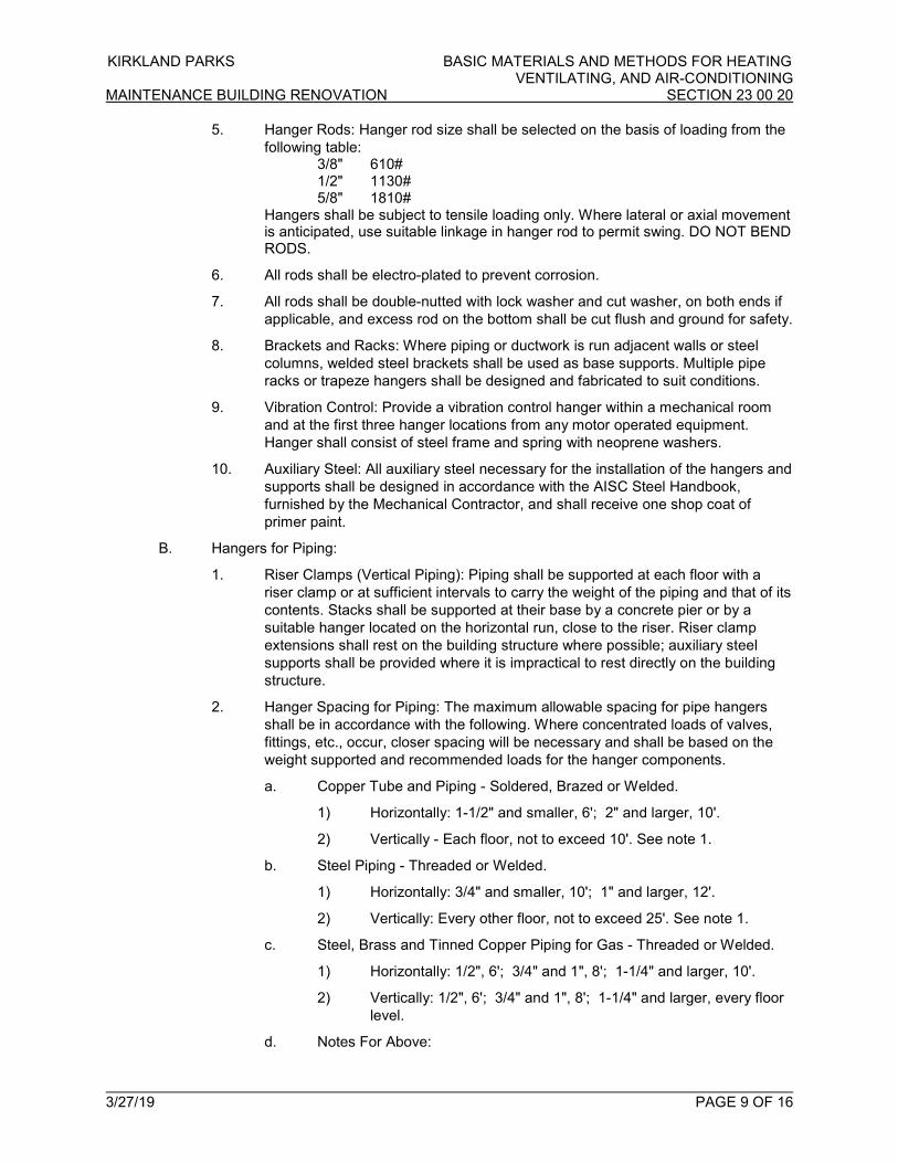
KIRKLAND PARKS BASIC MATERIALS AND METHODS FOR HEATING VENTILATING, AND AIR-CONDITIONING
MAINTENANCE BUILDING RENOVATION SECTION 23 00 20
3/27/19 PAGE 9 OF 16
5. Hanger Rods: Hanger rod size shall be selected on the basis of loading from the
following table: 3/8" 610# 1/2" 1130# 5/8" 1810# Hangers shall be subject to tensile loading only. Where lateral or axial movement is anticipated, use suitable linkage in hanger rod to permit swing. DO NOT BEND RODS.
6. All rods shall be electro-plated to prevent corrosion.
7. All rods shall be double-nutted with lock washer and cut washer, on both ends if
applicable, and excess rod on the bottom shall be cut flush and ground for safety.
8. Brackets and Racks: Where piping or ductwork is run adjacent walls or steel
columns, welded steel brackets shall be used as base supports. Multiple pipe
racks or trapeze hangers shall be designed and fabricated to suit conditions.
9. Vibration Control: Provide a vibration control hanger within a mechanical room
and at the first three hanger locations from any motor operated equipment.
Hanger shall consist of steel frame and spring with neoprene washers.
10. Auxiliary Steel: All auxiliary steel necessary for the installation of the hangers and
supports shall be designed in accordance with the AISC Steel Handbook,
furnished by the Mechanical Contractor, and shall receive one shop coat of
primer paint.
B. Hangers for Piping:
1. Riser Clamps (Vertical Piping): Piping shall be supported at each floor with a
riser clamp or at sufficient intervals to carry the weight of the piping and that of its
contents. Stacks shall be supported at their base by a concrete pier or by a
suitable hanger located on the horizontal run, close to the riser. Riser clamp
extensions shall rest on the building structure where possible; auxiliary steel
supports shall be provided where it is impractical to rest directly on the building
structure.
2. Hanger Spacing for Piping: The maximum allowable spacing for pipe hangers
shall be in accordance with the following. Where concentrated loads of valves,
fittings, etc., occur, closer spacing will be necessary and shall be based on the
weight supported and recommended loads for the hanger components.
a. Copper Tube and Piping - Soldered, Brazed or Welded.
1) Horizontally: 1-1/2" and smaller, 6'; 2" and larger, 10'.
2) Vertically - Each floor, not to exceed 10'. See note 1.
b. Steel Piping - Threaded or Welded.
1) Horizontally: 3/4" and smaller, 10'; 1" and larger, 12'.
2) Vertically: Every other floor, not to exceed 25'. See note 1.
c. Steel, Brass and Tinned Copper Piping for Gas - Threaded or Welded.
1) Horizontally: 1/2", 6'; 3/4" and 1", 8'; 1-1/4" and larger, 10'.
2) Vertically: 1/2", 6'; 3/4" and 1", 8'; 1-1/4" and larger, every floor
level.
d. Notes For Above:
KIRKLAND PARKS BASIC MATERIALS AND METHODS FOR HEATING VENTILATING, AND AIR-CONDITIONING
MAINTENANCE BUILDING RENOVATION SECTION 23 00 20
3/27/19 PAGE 10 OF 16
1) Vertical water lines may be supported in accordance with
recognized engineering principles with regard to expansion and
contraction when first approved by the Authority Having
Jurisdiction.
3. Hangers - Horizontal Piping:
a. General: All hangers shall be provided with means of vertical adjustment.
The following schedule shall be followed to select acceptable hangers for
the type of service.
1) Non-Insulated steel Piping:
a) Adjustable Split Ring Swivel Hanger
b) Adjustable steel Band Hanger
c) Clevis Hanger
2) Non-Insulated Copper Piping:
a) Copper Tubing Hanger
b) Copper Tubing Band Hanger
c) Copper Tubing Clevis Hanger
3) Insulated Steel Piping:
a) Adjustable Steel Band Hangers with Shield
b) Clevis hanger with Shield.
4) Insulated Copper Piping:
a) Adjustable steel Band Hanger with Shield.
b) Clevis hanger with Shield.
5) Insulated pipe inserts shall be provided at hanger, support,
anchor, and guide locations on piping requiring insulation. See
paragraph “Inserts at Hangers and Supports” in this Section.
b. Trapeze Hangers: Where piping is grouped in parallel, provide
manufactured strut or trapeze hangers consisting of two steel angles
bolted back-to-back, with space between for a hanger rod at each end.
Where the length of angles is greater than 24", there shall be three rod
supports. Piping shall be able to move independently, and hanger
spacing shall be dictated by the smallest pipe.
c. Anchors, Guides and Sliding Supports: Shall be as shown on the
drawings or as necessary to prevent excessive stress in either piping or
equipment.
C. Hangers for Ductwork:
1. Reference and comply with SMACNA HVAC Duct Construction Standards -
Metal and Flexible Table 4-1 - Rectangular Duct Hangers Minimum Size, and
Table 4-2 - Minimum Hanger Sizes for Round Duct for the following:
a. Strap and Rod Sizes
b. Hanger Spacing
2. Steel Cables

KIRKLAND PARKS BASIC MATERIALS AND METHODS FOR HEATING VENTILATING, AND AIR-CONDITIONING
MAINTENANCE BUILDING RENOVATION SECTION 23 00 20
3/27/19 PAGE 11 OF 16
a. Galvanized-Steel Ducts: Galvanized steel complying with ASTM A 602
b. Stainless-Steel ducts: Stainless steel complying with ASTM A 492.
c. End Connections: Cadmium-plate steel assemblies with brackets, swivel,
and bolts designed for duct hanger service, with an automatic locking
and clamping device.
3. Duct Attachments: Sheet-metal screws, blind rivets, or self-tapping metal screws,
compatible with duct materials.
4. Support materials shall match ductwork materials (i.e. provide stainless steel
support materials for stainless steel duct, galvanized steel support materials for
galvanized steel ducts, and aluminum support materials for aluminum ducts).
5. Hanger and Support Installation:
a. Reference Table 4-1 - Rectangular Duct Hangers Minimum Size, and
Table 4-2 - Minimum Hanger Sizes for Round Duct.
b. Support vertical ducts with steel angles or channel secured to the sides
of the duct with welds, bolts, sheetmetal screws, or blind rivets; support
at each floor and at a maximum interval of 16 feet.
c. Install upper attachments to structure. Select and size upper attachments
with pull-out, tension, and shear capacities appropriate for supported
loads and building materials where used.
3.12 CUTTING AND PATCHING (NEW WORK)
A. Furnish dimensions and locations of openings to other Contractors doing the work.
Provide ample time to avoid delays and unnecessary labor. Cutting and patching made
necessary to admit work, repair defective material or workmanship, or by neglect to
anticipate proper requirements, shall be done by the General Contractor at the expense
of the Mechanical Contractor.
3.13 CUTTING AND PATCHING (EXISTING STRUCTURE)
A. All necessary cutting and patching of existing structures necessary for installation of
mechanical work shall be done by the Mechanical Contractor as directed by the Owner's
representative.
B. All surfaces must be patched upon completion of the work to the satisfaction of the
Owner's representative. Final finish of all patched surfaces shall be done per
Architectural finish schedule, by the General Contractor. All excavation necessary for the
Mechanical Contractor shall be performed by the MC. Surfaces shall be patched as
hereinbefore specified and all backfilling shall be done in accordance with requirements
of this section and other related notes in the Contract Documents. If none specified,
restore to original condition.
3.14 ACCESSIBILITY
A. Locate valves, damper operators, etc., so as to be easily accessible in mechanical
spaces or through access panels, specified hereinafter. Otherwise, obtain Owner's
representative's approval of location.
B. Any equipment requiring maintenance clearances for servicing of filters, motors,
compressors, etc., shall be carefully installed to avoid servicing problems. Failure of
contractor to comply with this requirement shall be sufficient cause for contractor to make
all necessary changes at no cost to the Owner. To avoid problems with interpretation of
the NEC, allow 42" for all electrical clearances.

KIRKLAND PARKS BASIC MATERIALS AND METHODS FOR HEATING VENTILATING, AND AIR-CONDITIONING
MAINTENANCE BUILDING RENOVATION SECTION 23 00 20
3/27/19 PAGE 12 OF 16
3.15 ACCESS DOORS AND PANELS
A. Locations of panels shall be carefully selected during construction, so as not to be
located behind cabinets, etc. Coordinate closely with the Architectural and Electrical
Plans before installing panels.
B. In areas such as janitor's room or on painted walls, etc., access panels shall be prime-
coated and painted by the General Contractor; install before surrounding surfaces have
been painted. In areas such as toilet rooms, the access panels shall be stainless steel or
chrome-plated. In other finished areas such as on ceilings, all access panels shall have
the same type of finished surface as that of the surrounding area.
C. Verify with the Owner's representative location and finish prior to ordering; failure to get
the Owner's representative's approval may result in replacement of access panels at the
Mechanical Contractor's expense. Minimum size of access doors is 12" x 12"; actual size
depends on the specific circumstance, and panel shall be large enough to accomplish
replacement or repair of the item requiring access. The Owner's representative shall have
the final say on whether or not the access is of sufficient size.
D. Provide access panels for all concealed valves for all piping.
E. Doors shall have cylinder lock latches, all keyed alike.
F. Provide fire-rated access doors for one-hour or two-hour rated walls and ceilings; units
shall be UL labeled.
3.16 MECHANICAL ACCESSES
A. Provide suitable access to all mechanical equipment requiring servicing, maintenance,
replacement, or repair. In concealed spaces where access has not been provided by the
Architect by means of doors, hatchways, walkways or other means, provide wall or
ceiling access doors of a type suitable to the Owner's representative, sized to provide
easy access to all equipment. Location of such doors shall be coordinated with the work
of the other trades, to avoid conflict therewith, and such locations shall be approved by
the Owner's representative prior to installation of access panels.
B. In addition to building access openings, provide access panels on ducts where required
to service fire dampers, damper operators, and other associated equipment. All access
doors providing access to mechanically furnished panels, control boxes and filter
compartments shall be provided with fully-hinged, easily-opened access doors. Minimum
size is 12" x 12", unless access area prevents that size. Consult Owner's representative
prior to installing smaller sizes.
3.17 PAINTING, TAGS, ETC.
A. Field painting of all mechanical equipment, piping etc., located in and exposed in
occupied spaces, shall be by the General Contractor. See Architectural painting
specification.
B. Identification Tags: Provide identification tags for each main shutoff and control valve
throughout the building indicating the system served. Tags shall be black phenolic plastic
with white engraved inscription attached with chrome chain.
C. Mechanical Room: Provide valve tag lists under glass, one for the Boiler Room and one
for the remaining areas of the building. Coordinate location with Owner's representative.
D. Each major item of Mechanical Equipment shall be provided with the name of the item,
i.e., Exhaust Fan No. 2, etc., in labels of black phenolic plastic with white engraved
inscription. Minimum size of lettering is 1" with a maximum of 2". Select appropriate sizes
KIRKLAND PARKS BASIC MATERIALS AND METHODS FOR HEATING VENTILATING, AND AIR-CONDITIONING
MAINTENANCE BUILDING RENOVATION SECTION 23 00 20
3/27/19 PAGE 13 OF 16
for the size of the equipment being labeled. Align labels with edges of equipment and
locate labels so as to be visible. For ceiling exhaust fans, provide additional tag on grille.
E. Pipe Markers:
1. Piping throughout the building shall be equal to Brady Corporation No. B-946,
M.S.I. No. MS-900, meeting or exceeding ANSI A13.10-1981. Pipe markers shall
consist of two wraps of arrows in the direction of flow, color, and wording as
indicated in the schedule following. Stencils shall be visibly located and spaced
on maximum 20'-0" centers for long straight pipe runs. Stencils shall be located
on both sides of a wall, within the first 3'.
2. Color Code Schedule: (Service, Color, Stencil) Condensate Yellow COND. Waste and Vent Lines Yellow D.W.V. Gas Piping Yellow GAS
3. Ceiling Tile Access Labels: Where it is necessary to remove ceiling tile(s) to
access mechanical equipment, backdraft dampers, motorized dampers, remote
control sensors, valves/controllers, combination fire/smoke dampers, filters,
valves, volume dampers, etc., provide and install round 1/2" diameter, yellow,
self-adhesive labels on the metal ceiling grid, visible near all four corners of each
tile requiring removal.
3.18 TEMPORARY HEAT
A. Heating equipment may be not be used as temporary heating units during construction
3.19 FIRE INTEGRITY
A. All penetrations of fire-rated walls, ceilings, roofs or floors via ductwork, piping and air
terminals must be protected by fire dampers, fire/smoke dampers, appropriately-rated
assemblies, and caulking to maintain integrity of structure.
3.20 CLEANING UP
A. Comply with requirements of the General Specifications.
1. Ducts shall be maintained as clean as possible during erection, and shall be
blown clean before the building painting operations are started. Ducts and
apparatus casings shall be thoroughly cleaned before fans and filters are
operated. Installed ductwork and equipment openings shall be sealed to prevent
contamination of construction dust, debris and moisture. Uninstalled ductwork
and equipment shall be securely covered to prevent contamination or the
insulation getting wet. Uninstalled ductwork and equipment shall be stored on
pallets or dunnage that prevents water reaching the ductwork. If ductwork or
equipment is found to be dirty or wet, this contractor shall be responsible for
replacing such items. Contaminated or wet duct shall be spray painted with high
visibility paint and removed from the site immediately. After equipment has been
used for any purpose, such as adjusting, testing, or temporary ventilation, filters
shall be replaced and exhaust/return ducts shall be cleaned. Use temporary
filters with 80% to 85% filter efficiency during construction. Cover all openings
with temporary filters if startup, test and balance, or commissioning starts prior to
all work being completed in the building.
2. Remove tags, shipping labels, etc., from all ductwork in exposed areas, whether
ductwork is painted or not.
3.21 CAULKING
KIRKLAND PARKS BASIC MATERIALS AND METHODS FOR HEATING VENTILATING, AND AIR-CONDITIONING
MAINTENANCE BUILDING RENOVATION SECTION 23 00 20
3/27/19 PAGE 14 OF 16
A. Caulk all openings and flash around all piping, equipment, and ductwork passing through
roof, floor, and walls. All caulking shall be water resistant. See also paragraph "Fire
Integrity" for rated walls, ceilings, roofs, or floor penetrations.
B. All piping and ductwork penetrations of walls, ceilings, and floors shall be caulked. A
chrome-plated escutcheon plate shall be installed at each visible piping penetration of
walls, ceilings, or floors. All duct penetrations of walls, ceilings or floors shall be flashed
with 3" x 3" 18 gauge galvanized sheet metal angle for concealed ducts, and stainless
steel angle for exposed ducts.
3.22 OPERATION OF EQUIPMENT AND SYSTEMS
A. Contractor is responsible during all periods of balancing and testing. Provide temporary
utilities as required.
3.23 TESTS, ADJUSTMENTS AND INSPECTION
A. Test all work thoroughly and systematically, both during construction and after
completion. Notify Owner's representative 48 hours in advance of all tests. Tests shall be
maintained until approved. Tests shall be as hereinafter specified.
B. The Contractor shall test the completed installation as in regular service. Any defects or
imperfections that may show up are to be promptly corrected. The Contractor shall
guarantee the entire system and all parts thereof for a period of one year from date of
final acceptance. The Contractor shall repair or replace any part which may show signs of
failure during that time, if such failure, in the opinion of the Owner's representative, is due
to imperfections in material or to improper workmanship.
C. No system, whether prescribed for testing or not, shall be covered or concealed below
ground, in walls, in ceiling spaces, or generally from ease of viewing, without first
notifying the Owner's representative. Failure to notify the Owner's representative for
inspection of concealed systems shall be cause to require this contractor to uncover and
recover such systems at no additional cost to Owner.
D. A log of all tests shall be kept. The log shall note, dates, time of day test started, system
or portion of system tested, length of test, test results, and who witnessed the test (AHJ,
Owner's representative, or GC). Contractor shall insert legible name of witnesses.
Contractor to submit a copy of the contractor's test log monthly to the Owner's
representative.
E. Review the project to determine when final inspection is appropriate and advise Owner's
representative. Mechanical Contractor is required to complete his work before requesting
final inspection.
F. See specification section of piping used for test methods or procedures used.
G. Conduct refrigeration leak test on all DX equipment prior to installation on or in buildings.
H. Prior to repair, modification or tying into existing hydronic systems, take test samples
from the system to be analyzed for glycol type, concentration, and/or other ingredients.
Test report shall be forwarded to the Owner's representative.
3.24 FINAL INSPECTION
A. This contractor shall thoroughly review and inspect the project to determine when final
inspection is required, and shall so advise the Owner's representative. It shall be
understood that the work is to be essentially complete. If such is not the case and more
than one final inspection and one backcheck are necessary, this Contractor may be billed
for the additional backchecks at the then governing rate for the personnel involved. The
final inspection punchlist shall be legibly signed on a copy of the punch list by a person
KIRKLAND PARKS BASIC MATERIALS AND METHODS FOR HEATING VENTILATING, AND AIR-CONDITIONING
MAINTENANCE BUILDING RENOVATION SECTION 23 00 20
3/27/19 PAGE 15 OF 16
responsible for the trade involved, and transmitted to the Owner’s representative, before
a backcheck will be scheduled.
3.25 PROTECTION AND CLEANING
A. All equipment and material installed by this contractor shall be properly protected from
damage during the course of construction.
B. In attic or other spaces where piping such as condensate drains, heating lines,
refrigeration lines, etc. have been installed at floor level and interfere with foot traffic, the
Mechanical Contractor shall provide covers to protect this piping. Wood or other such
material will be acceptable. Where duct plenums or duct runs interfere with normal traffic
patterns of maintenance personnel, the sheet metal contractor shall provide a wooden
"bridge" over the ducts to prevent damage.
C. Protect walking paths in mechanical spaces. Maintain 6'-8" headroom minimum, for all
piping and ductwork. If required clearance is not possible, obtain permission from the
Owner's representative to violate the above requirement, and comply with protective
measures required.
3.26 SPECIAL PROTECTION
A. Exercise maximum precaution to protect the building and equipment from damage of any
kind, and in particular, prevent water and dust seepage into new equipment.
3.27 BALANCING WORK
A. Provide Testing, Adjusting and Balancing as required in this section of the specification.
3.28 INSTRUCTION PERIODS FOR OWNER'S PERSONNEL
A. Scope: Following installation of mechanical work, have representatives of installation
tradesmen conduct demonstrations and instruction periods to point out locations of
servicing points and required points of maintenance to Owner's representatives.
B. General Description of Instruction Periods: Each period shall include preliminary
discussion and presentation of information from maintenance manuals with appropriate
references to drawings, followed by tours of building areas explaining maintenance
requirements, access methods, servicing and maintenance procedures, equipment
cleaning procedures, temperature control settings, and available adjustments.
C. Scheduling of Instruction Periods: Notice of Contractor's readiness to conduct such
instruction and demonstration shall be given to the Owner's representative at least two
weeks prior to the instruction periods, and agreement reached as to the date at which the
instruction periods are to be performed. Advise Owner's representative two weeks prior to
date when ready to conduct instruction and demonstrations; receive approvals of
proposed date prior to making final arrangements.
D. Schedule an additional instruction period for the off-season. That is, if initial instruction
period takes place during the heating season, schedule another during the cooling
season, or vice versa.
3.29 ON-SITE OBSERVATIONS AND SAFETY MEASURES
A. During its progress, all work shall be subject to observation by the Owner's
representative, and of the National Board of Fire Underwriters, State and Local
Inspectors. The Engineer has not been retained or compensated to provide design and
construction review services relating to the Contractor's safety precautions or to means,
methods, techniques, sequences or procedures required for the Contractor to perform his
work. The Contractor will be totally responsible for conditions of the jobsite, including
KIRKLAND PARKS BASIC MATERIALS AND METHODS FOR HEATING VENTILATING, AND AIR-CONDITIONING
MAINTENANCE BUILDING RENOVATION SECTION 23 00 20
3/27/19 PAGE 16 OF 16
safety of all persons and property during performance of the work. This requirement will
apply continuously and not be limited to normal working hours. The duty of the Owner's
representative to conduct construction observations of the Contractor's performance is
not intended to include review of the adequacy of the Contractor's safety measures in,
on, or near the construction site. It shall be the Contractor's responsibility to comply with
"Safety and Health Regulations for Construction" in the Federal Register by the U.S.
Department of Labor. Contractor shall be responsible for providing all such safety
measures and shall consult with the State and/or Federal Safety Inspector for
interpretation whenever in doubt as to whether he is or is not in compliance with State
and/or Federal regulations. Furthermore, the Contractor distinctly assumes all risk or
damage or injury to any persons or property wherever located resulting from any action
or operation under this contract or in connection with the work.
3.30 CONTINUITY OF BUILDING UTILITIES AND SHUTDOWNS
A. General: Continuity of utilities services in the building shall be maintained at all times as
required to provide heat, water, lighting, and power to all portions of the building. Utility
systems shutdowns required for extensions, alterations or connections of new services
shall be accomplished in accordance with the following requirements.
3.31 DRAFT STOPS
A. It shall be the responsibility of each contractor performing his trade to verify with
Architectural Plans and to maintain the integrity of draft stops, whenever his work
requires penetration of these areas. Patch as required to maintain integrity of draft stops.
3.32 SYSTEM STARTUP
A. Provide the services of manufacturer's field representative for starting and testing
equipment.
B. Prepare a manufacturer's startup report, and turn over to the Owner's representative and
Commissioning Agent.
3.33 COMMISSIONING
A. This Contractor will be required to participate in the commissioning process. See Section
23 08 00 and the Commissioning Section in the Architectural section of the Specification.
The Mechanical Contractor shall complete the start-up forms and be available to assist in
the commissioning process. The Mechanical Contractor shall include in his bid all cost
associated with his portion of the commissioning process.
B. As a minimum, the following Mechanical Items shall be commissioned, see
Commissioning section.
1. All HVAC equipment.
2. Exhaust fans.
3. Energy management and control systems.
***END OF SECTION 23 00 20***
KIRKLAND PARKS INDENTIFICATION FOR HVAC PIPING AND EQUIPMENT MAINTENANCE BUILDING RENOVATION SECTION 23 05 53
3/27/19 PAGE 1 OF 3
PART l - GENERAL
1.01 SECTION INCLUDES
A. Nameplates.
B. Tags.
C. Pipe Markers and Arrows.
D. Ductwork Identification Nameplates.
1.02 REFERENCE STANDARDS
A. ASME A13.1 - Scheme for the Identification of Piping Systems; The American Society of
Mechanical Engineers.
B. Reference standards shall be the latest revision as accepted by the local Authority
Having Jurisdiction.
1.03 SUBMITTALS
A. List: Submit list of wording, symbols, letter size, and color coding for mechanical
identification, including matching size and colored arrows.
B. Chart and Schedule: Submit valve chart and schedule, including valve tag number,
location, function, and valve manufacturer's name and model number.
C. Product Data: Provide manufacturers catalog literature for each product required.
D. Project Record Documents: Record actual locations of tagged valves, on As-Builts.
1.04 QUALITY ASSURANCE
A. Perform work in accordance with applicable codes.
PART ll - PRODUCTS
2.01 MANUFACTURERS
A. Brady Corporation
B. Seton Identification Products
C. Marking Services, Inc.
D. Approved equal
2.02 NAMEPLATES
A. Description: Laminated three-layer plastic with engraved letters.
1. Letter Color: White.
2. Letter Height, Equipment: 1 -1/2".
3. Background Color: Black.
2.03 VALVE TAGS
A. Metal Tags: Brass with stamped letters; tag size minimum 1-1/2 inch diameter with
smooth edges.
B. Tag Lettering: First Line = System Abbreviation; Second Line = Consecutive Valve
Numbers, staring at 01.
C. Beaded Chain: #6 x 4-1/2" - Nickel Plated.

KIRKLAND PARKS INDENTIFICATION FOR HVAC PIPING AND EQUIPMENT MAINTENANCE BUILDING RENOVATION SECTION 23 05 53
3/27/19 PAGE 2 OF 3
2.04 PIPE MARKERS & ARROWS
A. Color: Conform to ASME A13.1.
B. Plastic Tape Pipe Markers: Flexible, vinyl film tape with pressure sensitive adhesive
backing and printed markings.
C. Plastic Tape Pipe Arrows: Nominal sizes and colors to match pipe markers. 1", 2" and 4".
D. Size of pipe markers:
1. 3/4" to 1-1/4" OSD of Covering = 1/2" letters.
2. 1-1/2" to 2" OSD of Covering = 3/4" letters.
3. 2-1/2" to 6" OSD of Covering = 1-1/4" letters.
2.05 DUCTWORK IDENTIFICATION NAMEPLATES
A. Description:
1. Plastic Laminate 1-1/4" letters and arrows.
2. Vinyl Markers 1-1/4" letters and arrows.
3. Color per ASME standards.
PART lll - EXECUTION
3.01 PREPARATION
A. Degrease and clean surfaces to receive adhesive for identification materials.
3.02 INSTALLATION
A. Install plastic nameplates and markers with corrosive-resistant mechanical fasteners, or
adhesive. Apply with sufficient adhesive to ensure permanent adhesion.
B. Install tags with nickel plated chain.
C. Install plastic pipe markers in accordance with manufacturer's instructions. Install a
circular wrap of arrows at each end of the pipe marker.
D. Install plastic tape pipe markers complete around pipe in accordance with manufacturer's
instructions.
E. Identify all mechanical equipment; air handling units, fans and heater etc. with plastic
nameplates.
F. Identify control panels and major control components outside panels with plastic
nameplates.
G. Identify ALL valves with tags.
H. Tag automatic controls, instruments, valves and relays. Key to control schematic, show
on control As-Builts. Provide tags identical to valve tags. First line = abbreviation [EMCS].
Number consecutively starting at 01. Provide Valve Chart Frames and Control Device
Lists on walls in an accessible location, well lighted space, in each Mechanical Space.
(Does not include Janitor Rooms).
I. Identify piping, concealed or exposed, with plastic pipe markers. Identify service, and
flow direction. Install in clear view and align with axis of piping. Locate identification not to
exceed 20' on center for straight runs, including risers and drops, adjacent to each valve
and tee, at each side of penetration of structure or enclosure, and at each obstruction.
J. Identify all ductwork with plastic or vinyl nameplates. Identify with air handling unit
identification number, system (Outside Air, Return Air, Exhaust Air, Supply Air, etc.) and

KIRKLAND PARKS INDENTIFICATION FOR HVAC PIPING AND EQUIPMENT MAINTENANCE BUILDING RENOVATION SECTION 23 05 53
3/27/19 PAGE 3 OF 3
area served. Locate identification as ducts leave or return to Air Handling Unit, on duct
runs not to exceed 20' on center, adjacent each branch, at each side of penetration of
structure or enclosure, and at each obstruction. air handling unit, at each side of
penetration of structure or enclosure, and at each obstruction. Do not install labels on
exposed ductwork.
***END OF SECTION 23 05 53***

KIRKLAND PARKS TESTING, ADJUSTING, AND BALANCING MAINTENANCE BUILDING RENOVATION SECTION 23 05 93
3/27/19 PAGE 1 OF 12
PART l - GENERAL
1.01 SECTION INCLUDES
A. Testing, adjustment, and balancing of air systems.
B. Measurement of final operating condition of HVAC systems.
C. Testing, adjusting, and balance of domestic water.
D. Commissioning activities.
1.02 RELATED REQUIREMENTS
A. Section 23 08 00 - Commissioning of HVAC.
1.03 REFERENCE STANDARDS
A. AABC MN-1 - AABC National Standards for Total System Balance; Associated Air
Balance Council.
B. ASHRAE Standard 111 - Practices for Measurement, Testing, Adjusting and Balancing of
Building Heating, Ventilation, Air-Conditioning, and Refrigeration Systems; American
Society of Heating, Refrigerating and Air-Conditioning Engineers, Inc.
C. NEBB (TAB) - Procedural Standards for Testing Adjusting Balancing of Environmental
Systems; National Environmental Balancing Bureau.
D. SMACNA (TAB) - HVAC Systems Testing, Adjusting, and Balancing; Sheet Metal and Air
Conditioning Contractors' National Association.
E. Reference standards shall be the latest revision as accepted by the local Authority
Having Jurisdiction.
1.04 SUBMITTALS
A. Qualifications: Submit name of Testing, Adjusting and Balancing agency and TAB
supervisor within 30 days after award of the Mechanical Contract by the General
Contractor. Include a list of the last 12 projects completed with a list of the respective
Owner's representatives and a contact phone number for each.
B. TAB Plan: Submit a written plan indicating the testing, adjusting, and balancing standard
to be followed and the specific approach for each system and component.
1. Submit for Review.
2. Submit for forwarding to Owner’s Commissioning Authority.
3. Submit plan twelve weeks prior to starting the testing, adjusting, and balancing
work, or sooner.
4. Include at least the following in the plan:
a. List of all air flow, water flow, system capacity, and efficiency
measurements to be performed and a description of specific test
procedures, parameters, and formulas to be used.
b. Copy of field checkout sheets and logs to be used, listing each piece of
equipment to be tested, adjusted and balanced with the data cells to be
gathered for each.
c. Identification and types of measurement instruments to be used and their
most recent calibration date.

KIRKLAND PARKS TESTING, ADJUSTING, AND BALANCING MAINTENANCE BUILDING RENOVATION SECTION 23 05 93
3/27/19 PAGE 2 OF 12
d. Discussion of what notations and markings will be made on the ductwork
and piping drawings during the process.
e. Final test report forms to be used.
f. Detailed step-by-step procedures for TAB work for each system and
issue, including:
1) Terminal flow calibration (for each terminal type).
2) Diffuser proportioning.
3) Branch/sub-main proportioning.
4) Total flow calculations.
5) Rechecking.
6) Diversity issues.
g. Expected problems and solutions, etc.
h. Details of how TOTAL flow will be determined; for example:
1) Air: Sum of terminal flows via control system calibrated readings
or via hood readings of all terminals, supply (SA) and return air
(RA) pitot traverse, SA or RA flow stations.
2) Water: Pump curves, circuit setter, flow station, ultrasonic, etc.
i. Specific procedures that will ensure that both air and water side are
operating at the lowest possible pressures and methods to verify this.
j. Confirmation of understanding of the outside air ventilation criteria under
all conditions.
k. Method of verifying and setting minimum outside air flow rate will be
verified and set and for what level (total building, zone, etc.).
l. Methods for making coil or other system plant capacity measurements, if
specified.
m. Time schedule for TAB work to be done in phases (by floor, etc.).
n. Time schedule for deferred or seasonal TAB work, if specified.
o. Exhaust fan balancing and capacity verifications, including any required
room pressure differentials.
p. Procedures for field technician logs of discrepancies, deficient or
uncompleted work by others, contract interpretation requests and lists of
completed tests (scope and frequency).
q. Procedures for formal progress reports, including scope and frequency.
r. Procedures for formal deficiency reports, including scope, frequency and
distribution.
C. Field Logs: Submit at least twice a week to General Contractor, Owner’s representative,
and Commissioning Authority. Label accordingly. If no field logs are submitted, it will be
assumed that no work was being done during this period.
D. Control System Coordination Reports: Communicate in writing to the controls installer all
setpoint and parameter changes made or problems and discrepancies identified during
TAB that affect, or could affect, the control system setup and operation.
KIRKLAND PARKS TESTING, ADJUSTING, AND BALANCING MAINTENANCE BUILDING RENOVATION SECTION 23 05 93
3/27/19 PAGE 3 OF 12
E. Progress Reports. Provide preliminary/hand-written balance report no later than one (1)
week after completion of work. No progress payments will be authorized if a preliminary
balance report has not been submitted.
F. Final Report: Indicate deficiencies in systems that would prevent proper testing, adjusting, and balancing of systems and equipment to achieve specified performance.
1. Submit draft copies of report for review prior to final acceptance of Project.
Provide final copies for Owner’s representative and for inclusion in Operating and
Maintenance manuals.
2. Provide reports in hard cover, 3-ring binder, complete with index page and
indexing tabs, with cover identification at front and side. Include set of reduced
drawings with air outlets and equipment identified to correspond with data
sheets, and indicating thermostat locations.
3. Include actual instrument list with manufacturer name, serial number, and date of
calibration.
4. Form of Test Reports: Use report format recommended by TAB standard. If
none of these apply, follow ASHRAE Standard 111.
5. Units of Measure: Report data in I-P (inch-pound) units only.
6. Include the following on the title page of each report:
a. Name of Testing, Adjusting, and Balancing Agency.
b. Address of Testing, Adjusting, and Balancing Agency.
c. Telephone number of Testing, Adjusting, and Balancing Agency.
d. Project name of project.
e. Project location of project.
f. Project Architect.
g. Project Mechanical Engineer.
h. Project General Contractor.
i. Project Mechanical Contractor.
j. Project Controls Contractor.
k. Owner's Commissioning Agent.
l. Report date.
G. Project Record Documents: Record actual locations of flow measuring stations and
balancing valves and rough setting.
1.05 DALT DUCT AIR LEAKAGE TESTING - ASSISTANCE
A. M.C. to provide HVAC equipment mechanics to operate and assist with HVAC equipment
and HVAC ductwork mechanics to provide the field required test ports and other
modifications needed to perform the DALT. M.C. to ensure that these support personnel
are present at the agreed upon times.
1.06 INSULATION PRIOR TO TAB OR DALT AIR LEAKAGE TESTING
A. Do not allow insulating of ductwork or piping prior to TAB and or DALT testing. If project
is behind schedule, the Owner’s representative may agree to partial insulation prior to
completion of testing, if the TAB contractor agrees.

KIRKLAND PARKS TESTING, ADJUSTING, AND BALANCING MAINTENANCE BUILDING RENOVATION SECTION 23 05 93
3/27/19 PAGE 4 OF 12
1.07 QUALITY ASSURANCE
A. Perform work in accordance with applicable codes.
B. M.C. to provide conformed construction drawings and specifications to the TAB firm, if
available. If not available, issue the same drawings that are being provided to the other
Subcontractors, along with any RFIs or Change Orders that may affect their work. The
M.C. is responsible to keep the TAB firm up to date with pertinent contract documents
and correspondence.
C. M.C. to provide approved equipment submittals and project schedule for the use by the
TAB subcontractor.
1.08 WARRANTY
A. Include a warranty for 24 months after final acceptance by the Owner, during which time
the Owner may request a recheck, or resetting of any outlet, coil or device listed in the
project test report. TAB contractor to contact other project subcontractors if their technical
assistance is required to make any test or adjustments required. Maximum number of
rechecks shall not exceed a yearly total of 5% of the entire project. However, if the
balance reports are proved to be inaccurate, the Owner may request the entire project be
re-balanced during the warranty period. See paragraph Commissioning in this Section for
recheck and failure criteria. The above warranty shall be included in the original contract
bid proposal.
PART ll - PRODUCTS - NOT USED
PART lll - EXECUTION
3.01 GENERAL REQUIREMENTS
A. Provide services for all mechanical equipment including both new and existing.
B. Perform total system balance in accordance with one of the following:
1. AABC MN-1, AABC National Standards for Total System Balance.
2. ASHRAE Standard 111, Practices for Measurement, Testing, Adjusting and
Balancing of Building Heating, Ventilation, Air-Conditioning, and Refrigeration
Systems.
3. NEBB Procedural Standards for Testing Adjusting Balancing of Environmental
Systems.
4. SMACNA HVAC Systems Testing, Adjusting, and Balancing.
C. Begin work after completion of systems to be tested, adjusted, or balanced and complete
work prior to Substantial Completion of the project.
D. TAB Agency Qualifications:
1. Certified by one of the following:
a. AABC, Associated Air Balance Council: www.aabchq.com; upon
completion submit AABC National Performance Guaranty.
b. NEBB, National Environmental Balancing Bureau: www.nebb.org.
c. TABB, The Testing, Adjusting, and Balancing Bureau of National Energy
Management Institute: www.tabbcertified.org.
E. TAB Supervisor Qualifications: Professional Engineer licensed in the State in which the
Project is located.

KIRKLAND PARKS TESTING, ADJUSTING, AND BALANCING MAINTENANCE BUILDING RENOVATION SECTION 23 05 93
3/27/19 PAGE 5 OF 12
F. TAB Team Members: Submit their qualifications along with the Companies qualifications
and the TAB Supervisor qualifications. TAB team approved to accomplish work on this
contract, must be full-time employees of the TAB agency. No other personnel are allowed
to do TAB work on this contract.
G. Pre-Qualified TAB Agencies:
1. Neudorfer Engineering (206) 621-1810.
2. Hardin & Sons (253) 862-6645.
3. Air Balance Associates (206) 528-4788.
3.02 EXAMINATION
A. Verify that systems are complete and operable before commencing work. Ensure the
following conditions:
1. Systems are started and operating in a safe and normal condition.
2. Temperature control systems are installed complete and operable.
3. Proper thermal overload protection is in place for electrical equipment.
4. Final filters are clean and in place. If required, have HVAC contractor replace or
install temporary media in addition to final filters.
5. Duct systems are clean of debris.
6. Fans are rotating correctly.
7. Fire and volume dampers are in place and open.
8. Air coil fins are cleaned and combed.
9. Access doors are closed and duct end caps are in place.
10. Air outlets are installed and connected.
11. Confirm duct system leakage is minimized. Have HVAC contractor coat or recoat
joints that may not be up to SMACNA standards prior to testing.
12. Properly sized strainer baskets, are clean and in place.
13. Service and balance valves are open.
B. Submit field reports. Report defects and deficiencies that will or could prevent proper
system balance.
C. The testing and balancing work is a part of the overall project, and shall be shown on the
project schedule with a reasonable time allotted to accomplish the work. If the Owner,
General Contractor and or other Subcontractors have delayed the project and there is no
time left for the testing and balancing to be performed, the following remedies shall be
considered by the Owner;
1. The time of completion shall be extended.
2. The Owner’s representative and General Contractor shall negotiate overtime for
the Test and Balancing Contractor to accelerate the time required to complete his
work.
3. The Owner’s representative may allow some systems and requirements to be
waived or extended to a later time period.

KIRKLAND PARKS TESTING, ADJUSTING, AND BALANCING MAINTENANCE BUILDING RENOVATION SECTION 23 05 93
3/27/19 PAGE 6 OF 12
4. Or other remedies as suggested by the Test and Balance Contractor that will
allow him to complete his work and is agreeable to the Owner’s representative
and General Contractor.
5. Any changes in the contract terms or specification requirements shall be in
writing prior to the testing and balancing work commencing.
D. Beginning of work means acceptance of existing conditions, or that a letter allowing
revised conditions has been received by the TAB contractor.
E. The TAB contractor shall exercise care while performing his work so as to avoid
damaging the work of other trades, particularly paint and ceiling tile. If damage is incurred
by the Test and Balance Contractor, repairs shall be made at their expense.
3.03 PREPARATION
A. Hold Pre-balancing meeting two weeks prior to starting TAB work.
1. Require attendance by all installers whose work will be tested, adjusted, or
balanced, plus General Contractor, Owner’s representative, and Owners
Commissioning Agent.
2. Complete Project Examination noted above prior to Pre-balancing meeting, so
that any problems found that would prevent balancing can be dealt with at the
meeting.
B. Provide instruments required for testing, adjusting, and balancing operations. Make
instruments available to Owner’s representative and Owner’s Commissioning Agent to
facilitate spot checks during testing.
C. Request HVAC contractor provide additional balancing devices as required.
3.04 ADJUSTMENT TOLERANCES
A. Air Handling Systems: Adjust to within plus or minus 10% of design for supply, return,
and exhaust systems.
B. Air Outlets and Inlets: Adjust total airflow to within plus or minus 10% of design to space.
Adjust outlets and inlets in space to within plus or minus 10% of design.
3.05 RECORDING AND ADJUSTING
A. Field Logs: Maintain written logs including:
1. Running log of events and issues.
2. Discrepancies, deficient or uncompleted work by others.
3. Contract interpretation requests.
4. Lists of completed tests.
B. Ensure recorded data represents actual measured or observed conditions.
C. Permanently mark settings of valves, dampers, and other adjustment devices allowing
settings to be restored. Set and lock memory stops.
D. Mark locations where traverse and other critical measurements were taken on the Plans
and cross reference the location in the final report.
E. After adjustment, take measurements to verify balance has not been disrupted or that
such disruption has been rectified.
F. Leave systems in proper working order; replace belt guards, close access doors, close
doors to electrical switch boxes, and restore thermostats to specified settings.
KIRKLAND PARKS TESTING, ADJUSTING, AND BALANCING MAINTENANCE BUILDING RENOVATION SECTION 23 05 93
3/27/19 PAGE 7 OF 12
G. At final inspection, recheck random selections of data recorded in report. Recheck points
or areas as selected and witnessed by the Owner’s representative and Owner’s
Commissioning Agent.
3.06 AIR SYSTEM PROCEDURE
A. Adjust air handling and distribution systems to provide required design supply, return,
and exhaust air quantities at site altitude.
B. Make air quantity measurements in ducts by Pitot tube traverse of entire cross sectional
area of duct.
C. Measure air quantities at air inlets and outlets.
D. Adjust distribution system to obtain uniform space temperatures free from objectionable
drafts and noise.
E. Use volume control devices to regulate air quantities only to extent that adjustments do
not create objectionable air motion or sound levels. Effect volume control by duct internal
devices such as dampers and splitters.
F. Vary total system air quantities by adjustment of fan speeds. Provide drive changes
required. Vary branch air quantities by damper regulation.
G. Provide system schematic with required and actual air quantities recorded at each outlet
or inlet.
H. Measure static air pressure conditions on air supply units, including filter and coil
pressure drops, and total pressure across the fan. Make allowances for 50% loading of
filters.
I. Adjust outside air automatic dampers, outside air, return air, and exhaust dampers for
design conditions.
J. Measure performance capacity tests for all coils, confirm manufacturers capacities, single
points test are acceptable for units below 7.5 tons, for units above 7.5 ton, average of
multiple readings in compliance with acceptable standards, is required.
K. Measure temperature conditions across outside air, return air, and exhaust dampers to
check leakage.
L. Where modulating dampers are provided, take measurements and balance at extreme
conditions. Balance variable volume systems at maximum air flow rate, full cooling, and
at minimum air flow rate, full heating.
M. Measure building static pressure and adjust supply, return, and exhaust air systems to
provide required relationship between each to maintain approximately 0.05” positive
static pressure near the building entries.
N. At completion, be sure all test holes in low pressure duct have pressure sealing plugs
installed; duct tape is not allowed. Test holes in high pressure duct shall employ threaded
and capped duct air fittings.
O. The Test and Balance contractor shall include in his bid the cost of one sheave change
for each belt driven air moving piece of equipment. If a sheave change is not required,
the test and balance contractor shall submit to the Owner a credit for the work that was
not required. The total cost of sheave changes shall be listed as a separate line item on
the Schedule of Values and submitted to the Owner’s representative for approval prior to
the first pay application.
3.07 WATER SYSTEM PROCEDURE

KIRKLAND PARKS TESTING, ADJUSTING, AND BALANCING MAINTENANCE BUILDING RENOVATION SECTION 23 05 93
3/27/19 PAGE 8 OF 12
A. Adjust water systems to provide required or design quantities. Test systems at design
fluid temperatures.
B. Effect adjustment of water distribution systems by means of balancing cocks, valves, and
fittings. Do not use service or shut-off valves for balancing unless indexed for balance
point.
3.08 COMMISSIONING
A. See Section 23 08 00 for additional requirements.
B. Perform prerequisites prior to starting commissioning activities.
C. Re-check final TAB report data as directed by the Owner's Commissioning Agent.
1. Original TAB agency shall execute the re-checks.
2. Use the same test instruments as used in the original TAB work.
3. Failure of more than 10% of the re-checked items of a given system shall result
in the rejection of the system TAB report; rebalance the system, provide a new
system TAB report, and repeat random re-checks.
4. For purposes of re-check, failure is defined as follows:
a. Air Flow of Supply and Return: Deviation of more than 10% of
instrument reading.
b. Minimum Outside Air Flow: Deviation of more than 20% of instrument
reading; for inlet vane or VFD outside air compensation system using
linear proportional control, deviation of more than 30% at intermediate
supply flow.
c. Temperatures: Deviation of more than one degree F.
d. Air and Water Pressures: Deviation of more than 10% of full scale of test
instrument reading.
5. For purposes of re-check, a whole system is defined as one in which
inaccuracies will have little or no impact on connected systems; for example, the
air distribution system served by one air handler or the hydronic chilled water
supply system served by a chiller or the condenser water system.
D. In the presence of the Commissioning Authority, verify that:
1. Final settings of all valves, splitters, dampers and other adjustment devices have
been permanently marked.
2. The air system is being controlled to the lowest possible static pressure while still
meeting design loads, less diversity. This shall include a review of TAB methods
and established control setpoints. Physically verify that at least one leg, from fan
to diffuser, during full cooling, has all balancing dampers for terminal units taking
off downstream of the static pressure sensor wide open, with the damper for the
terminal unit on the critical leg 90% or more open.
E. No seasonal tests are required.
3.09 MINIMUM DATA TO BE REPORTED
A. Electric Motors:
1. Manufacturer
2. Model/Frame

KIRKLAND PARKS TESTING, ADJUSTING, AND BALANCING MAINTENANCE BUILDING RENOVATION SECTION 23 05 93
3/27/19 PAGE 9 OF 12
3. HP/BHP
4. Phase, voltage, amperage from nameplate
5. Phase, voltage, amperage from actual, no load conditions.
6. RPM
7. Service factor
8. Starter size, rating, heater elements
9. Sheave Make/Size/Bore
B. V-Belt Drives:
1. Identification/location
2. Required driven RPM
3. Driven sheave, diameter and RPM
4. Belt, size and quantity
5. Motor sheave diameter and RPM
6. Center-to-center distance, maximum, minimum, and actual
C. Pumps:
1. Identification/number
2. Manufacturer
3. Size/model
4. Impeller
5. Service
6. Design flow rate, pressure drop, BHP
7. Actual flow rate, pressure drop, BHP
8. Discharge pressure
9. Suction pressure
10. Total operating head pressure
11. Shut-off, discharge and suction pressures
D. Combustion Equipment:
1. Manufacturer
2. Model number
3. Serial number
4. Firing rate
5. Overfire draft
6. Gas pressure at meter outlet
7. Gas flow rate
8. Heat input
9. Burner manifold gas pressure

KIRKLAND PARKS TESTING, ADJUSTING, AND BALANCING MAINTENANCE BUILDING RENOVATION SECTION 23 05 93
3/27/19 PAGE 10 OF 12
10. Percent excess air
11. Flue gas temperature at outlet
12. Ambient temperature
13. Heat output
E. Air Cooled Condensers:
1. Identification/number
2. Location
3. Manufacturer
4. Model number
5. Serial number
6. Refrigerant Pressures
7. Number of compressors
F. Cooling Coils:
1. Identification/number
2. Location
3. Service
4. Manufacturer
5. Air flow, design and actual
6. Entering air DB temperature
7. Entering air WB temperature
8. Leaving air DB temperature
9. Leaving air WB temperature
10. Saturated suction temperature
11. Air pressure drop
G. Heating Coils:
1. Identification/number
2. Location
3. Service
4. Manufacturer
5. Air flow, design and actual
6. Entering air temperature
7. Leaving air temperature
8. Air pressure drop
H. Air Moving Equipment:
1. Location
2. Manufacturer

KIRKLAND PARKS TESTING, ADJUSTING, AND BALANCING MAINTENANCE BUILDING RENOVATION SECTION 23 05 93
3/27/19 PAGE 11 OF 12
3. Model number
4. Serial number
5. Arrangement/Class/Discharge
6. Air flow, specified and actual
7. Return air flow, specified and actual
8. Outside air flow, specified and actual
9. Total static pressure (total external), specified and actual
10. Show filter static pressure, specified and actual
11. Inlet pressure
12. Discharge pressure
13. Sheave Make/Size/Bore
14. Number of Belts/Make/Size
15. Fan RPM
I. Return Air/Outside Air:
1. Identification/location
2. Design air flow
3. Actual air flow
4. Design return air flow
5. Actual return air flow
6. Design outside air flow
7. Actual outside air flow
8. Return air temperature
9. Outside air temperature
10. Required mixed air temperature
11. Actual mixed air temperature
12. Design outside/return air ratio
13. Actual outside/return air ratio
J. Exhaust Fans:
1. Location
2. Manufacturer
3. Model number
4. Serial number
5. Air flow, specified and actual
6. Total static pressure (total external), specified and actual
7. Inlet pressure
8. Discharge pressure

KIRKLAND PARKS TESTING, ADJUSTING, AND BALANCING MAINTENANCE BUILDING RENOVATION SECTION 23 05 93
3/27/19 PAGE 12 OF 12
9. Sheave Make/Size/Bore
10. Number of Belts/Make/Size
11. Fan RPM
K. Air Distribution Tests:
1. Air terminal number
2. Room number/location
3. Terminal type
4. Terminal size
5. Area factor
6. Design velocity
7. Design air flow
8. Test (final) velocity
9. Test (final) air flow
10. Percent of design air flow
***END OF SECTION 23 05 93***
KIRKLAND PARKS DUCT INSULATION MAINTENANCE BUILDING RENOVATION SECTION 23 07 13
3/27/19 PAGE 1 OF 5
PART l - GENERAL
1.01 SECTION INCLUDES
A. Glass Fiber Flexible Duct Wrap Insulation
B. Jackets for Duct Wrap Insulation
C. Duct Liner
D. Plenum Waterproofing
1.02 RELATED REQUIREMENTS
A. Section 22 05 53 - Identification for Plumbing Piping and Equipment.
B. Section 23 31 00 - HVAC Ductwork and Casings:
1.03 REFERENCE STANDARDS
A. ASTM B209 - Standard Specification for Aluminum and Aluminum-Alloy Sheet and Plate.
B. ASTM C553 - Specification for Mineral Fiber Blanket Thermal Insulation for Commercial
and Industrial Applications.
C. ASTM C612 - Standard Specification for Mineral Fiber Block and Board Thermal
Insulation.
D. ASTM C916 - Standard Specification for Adhesives for Duct Thermal Insulation.
E. ASTM C1071 - Standard Specification for Fibrous Glass Duct Lining Insulation (Thermal
and Sound Absorbing Material).
F. ASTM E84 - Standard Test Method for Surface Burning Characteristics of Building
Materials.
G. ASTM E96/E96M - Standard Test Methods for Water Vapor Transmission of Materials.
H. ASTM G21 - Standard Practice for Determining Resistance of Synthetic Polymeric
Materials to Fungi.
I. NFPA 255 - Standard Method of Test of Surface Burning Characteristics of Building
Materials; National Fire Protection Association.
J. SMACNA (DCS) - HVAC Duct Construction Standards - Metal and Flexible; Sheet Metal
and Air Conditioning Contractors' National Association; 2005.
K. UL 723 - Standard for Test for Surface Burning Characteristics of Building Materials;
Underwriters Laboratories Inc.
L. Reference standards shall be the latest revision as accepted by the local Authority
Having Jurisdiction.
1.04 SUBMITTALS
A. Product Data: Provide product description, thermal characteristics, list of materials and
thickness for each service, and locations.
B. Manufacturer's Instructions: Indicate installation procedures necessary to ensure
acceptable workmanship and that installation standards will be achieved.
1.05 QUALITY ASSURANCE
A. Perform work in accordance with applicable codes.
KIRKLAND PARKS DUCT INSULATION MAINTENANCE BUILDING RENOVATION SECTION 23 07 13
3/27/19 PAGE 2 OF 5
B. Applicator Qualifications: Company specializing in performing the type of work specified
in this section, with minimum 5 years of experience.
1.06 DELIVERY, STORAGE, AND HANDLING
A. Accept materials on-site in original factory packaging, labeled with manufacturer's
identification, including product density and thickness.
B. Do not store excess material in the building. Provide secure dry storage on-site, to store
material.
C. Protect insulation from weather and construction traffic, dirt, water, chemical, and
mechanical damage, by storing in original wrapping.
1.07 FIELD CONDITIONS
A. Maintain ambient temperatures and conditions required by manufacturers of adhesives,
mastics, and insulation cements.
B. Maintain temperature during and after installation for minimum period of 24 hours.
PART ll - PRODUCTS
2.01 REQUIREMENTS FOR ALL PRODUCTS OF THIS SECTION INSTALLED INSIDE BUILDINGS
A. Surface Burning Characteristics: Flame spread/Smoke developed index of 25/50,
maximum, when tested in accordance with ASTM E 84, NFPA 255, or UL 723.
2.02 MANUFACTURERS
A. Knauf Fiber Glass
B. Johns Manville Corporation
C. Owens Corning Corp
D. CertainTeed Corporation
E. Pittsburgh Corning Corporation
F. Armacell International
G. Approved equal.
2.03 GLASS FIBER, FLEXIBLE
A. Insulation: ASTM C553; flexible, noncombustible blanket.
1. 'K' value: 0.36 at 75 degrees F, when tested in accordance with ASTM C518.
2. Maximum Service Temperature: 450 degrees F.
3. Maximum Water Vapor Sorption: 5.0% by weight.
B. Usage: HVAC Air Distribution Systems Ductwork - Interior - Medium to Low
Temperatures.
C. Vapor Barrier Jacket:
1. Kraft paper with glass fiber yarn and bonded to aluminized film.
2. Moisture Vapor Permeability: 0.02 perm inch, when tested in accordance with
ASTM E96/E96M.
3. Secure with pressure sensitive tape.
D. Vapor Barrier Tape:

KIRKLAND PARKS DUCT INSULATION MAINTENANCE BUILDING RENOVATION SECTION 23 07 13
3/27/19 PAGE 3 OF 5
1. Kraft paper reinforced with glass fiber yarn and bonded to aluminized film, with
pressure sensitive rubber-based adhesive.
E. Tie Wire: Annealed steel, 16 gage.
2.04 DUCT LINER
A. Insulation: Incombustible glass fiber complying with ASTM C 1071; flexible blanket, rigid
board, and preformed round liner board with impregnated surface and edges coated with
polyvinyl acetate polymer or acrylic polymer shown to be fungus and bacteria resistant by
testing to ASTM G 21.
1. Apparent Thermal Conductivity: Maximum of 0.31 at 75 degrees F.
2. Service Temperature: Up to 250 degrees F.
3. Rated Velocity on Coated Air Side for Air Erosion: 5,000 fpm, minimum.
4. Minimum Noise Reduction Coefficients:
a. 1" Thickness: 0.45.
B. Usage: Line Duct as detailed in paragraphs below.
C. Adhesive: Waterproof, fire-retardant type, ASTM C916.
D. Liner Fasteners: Galvanized steel, welded with press-on head, per SMACNA standards.
2.05 PLENUM WATERPROOFING
A. Coordinate installation of a continuous self-adhering rubberized asphalt flashing, extend
up each side a minimum of 6" and extend from the weatherproof louver back 4' or to the
end of the plenum and up 6"; corners to be sealed watertight. Mechanical Contractor to
provide certification letter stating Plenum Waterproofing has been installed in all plenums;
provide a copy to the Owner's Commissioning Agent and Owner's representative.
PART lll - EXECUTION
3.01 EXAMINATION
A. Verify that ductwork pressurization has been tested before applying insulation materials.
B. Verify that surfaces are clean and dry, with foreign material removed.
3.02 INSTALLATION
A. Install in accordance with manufacturer's instructions.
B. Install in accordance with NAIMA National Insulation Standards; have a copy on site for
reference. Employ only skilled tradesmen specializing in this kind of work.
C. Insulated ductwork conveying air, below ambient temperature:
1. Provide insulation with vapor barrier jackets.
2. Finish with tape and vapor barrier jacket.
3. Continue insulation through walls, sleeves, hangers, and other duct penetrations.
4. Insulate entire system including fittings, joints, flanges, fire dampers, flexible
connections, and expansion joints.
D. Insulated ductwork conveying air above ambient temperature:
1. Provide with standard vapor barrier jacket.
KIRKLAND PARKS DUCT INSULATION MAINTENANCE BUILDING RENOVATION SECTION 23 07 13
3/27/19 PAGE 4 OF 5
2. Insulate fittings and joints. Where service access is required, bevel and seal
ends of insulation.
E. Ductwork Exposed in Mechanical Equipment Rooms below 10' above finish floor: Finish
with aluminum jacket.
F. Ductwork Exposed in finished Spaces: Finish with stainless steel jacket.
G. Duct Liner Application:
1. Adhere insulation with adhesive for 90% coverage.
2. Secure insulation with mechanical liner fasteners. Refer to SMACNA HVAC Duct
Construction Standards - Metal and Flexible for spacing.
3. Seal and smooth joints. Seal and coat transverse joints.
4. Seal liner surface penetrations with adhesive.
5. Duct dimensions indicated are net inside dimensions required for air flow.
Increase duct size to allow for insulation thickness.
3.03 SCHEDULES
A. Provide thickness of insulation to meet or exceed Washington State Energy Code and or
local codes whichever are more stringent.
B. Special Requirements - DUCT LINER.
1. Duct liner for this project will be 1" unless noted otherwise in Contract
documents.
2. Contractor to show extent of duct lining on shop drawings to avoid confusion,
omission and possible rejection.
3. Line ALL of the following ductwork (see exceptions in #4 below);
a. Rectangular Supply ductwork
b. Rectangular Return ductwork.
c. Rectangular Relief ductwork.
d. Rectangular Exhaust ductwork, from the fan to the last air terminal,
unless such ductwork contains corrosive gases.
1) Do not line fume hood or kitchen hood ductwork.
e. Rectangular Transfer Air ductwork.
f. Rectangular Outside Air ductwork.
4. Fiberglass liner shall not be used in the following applications:
a. Within 6' of outside air intakes or outside grilles. (Duct wrap shall be used
in these locations).
b. In air duct systems operating above 250 degrees F.
c. In systems conveying solids, particulates or corrosive gases.
d. In welding shop exhaust ductwork.
e. In ductwork operating at a velocity in excess of the liner’s maximum
recommended velocity.
f. Plenums exposed to the outside air, including intake, relief or exhaust
plenums.
KIRKLAND PARKS DUCT INSULATION MAINTENANCE BUILDING RENOVATION SECTION 23 07 13
3/27/19 PAGE 5 OF 5
g. In contact with any HVAC equipment wet surface.
5. Additional requirements may be shown on the plans and are in addition to the
requirements specified herein.
C. Special Requirements - DUCT WRAP.
1. Wrap all of the following ductwork:
a. Outside air ductwork within 6' of an outside air intake.
b. Concealed supply, return, and outside air ductwork and plenums, except
within 10' of the floor in Mechanical spaces. (Use blanket insulation
wrap.)
c. Exposed supply, return and outside air ductwork and plenums, located
within 10' of the floor in Mechanical spaces. Provide rigid insulation with
vapor barrier jacket.
d. Ductwork that is located on the exterior of the building: Wrap with
laminated flexible elastomeric cellular insulation.
e. Plenums.
f. Outside air and relief/exhaust air ductwork from damper to building
opening, louver, or hood. Insulation R-value is to match building
envelope insulation R-value regardless of location, per the requirements
of the Washington State Energy Code.
g. Blanket insulation for primary air ductwork (supply duct between AHU
and terminal units), regardless of location.
2. Duct wrap shall not be used in the following applications:
a. In conditioned spaces, do not wrap ductwork exposed to view within a
zone that serves that zone.
D. Provide insulation thicknesses per Washington State Energy Code as a minimum.
***END OF SECTION 23 07 13***

KIRKLAND PARKS MECHANICAL COMMISSIONING MAINTENANCE BUILDING RENOVATION SECTION 23 08 00
3/27/19 PAGE 1 OF 8
PART l - GENERAL
1.01 SUMMARY
A. This section covers the Mechanical Contractor's responsibilities, and that of his
subcontractors, for commissioning; each subcontractor or installer is responsible for the
installation of a particular system or equipment item to be commissioned, and is
responsible for the commissioning activities relating to that system or equipment item.
B. The Commissioning Authority (CA) directs and coordinates all commissioning activities
and provides Prefunctional Checklists and Functional Test Procedures for Contractor's
use. This specification is a supplement to the Owner's Commissioning Specification; its
intent is to make the Mechanical Contracting Team aware of their responsibilities under
the Commissioning requirements for this project. This specification should be considered
the minimum requirements; the Owner's Commissioning Specification is the Lead
Specification.
C. The entire HVAC system is to be commissioned, including commissioning activities for
the following specific items:
1. Control system.
2. Major and minor equipment items.
3. Piping systems and equipment, including plumbing systems.
4. Ductwork and accessories.
5. Terminal units.
6. Other equipment and systems explicitly identified elsewhere in Contract
Documents as requiring commissioning.
D. The Prefunctional Checklist and Functional Test requirements specified in this section
are in addition to, not a substitute for, inspection or testing specified in other sections.
1.02 RELATED REQUIREMENTS
A. Section 23 09 23 - Direct-Digital Control System for HVAC.
B. Section 23 09 13 - Instrumentation and Control Devices for HVAC.
C. Section 23 09 93 - Sequence of Operations for HVAC Controls.
D. Section 23 05 93 - Testing, Adjusting, and Balancing.
1.03 REFERENCE STANDARDS
A. ASHRAE Guideline 1 - The HVAC Commissioning Process; 1996
1.04 SUBMITTALS
A. HVAC Control System Documentation: Submit detailed sequences of operation, control
system drawings, and points list, as specified in Section 23 09 93.
1. Incorporate the sequence of operation information specified in other HVAC
specification sections.
2. Incorporate the shop drawing submittal information specified in the HVAC control
system section.
3. Submittals prepared for other sections may be used in preparation of this
documentation.
KIRKLAND PARKS MECHANICAL COMMISSIONING MAINTENANCE BUILDING RENOVATION SECTION 23 08 00
3/27/19 PAGE 2 OF 8
B. Updated Submittals: Keep the CA informed of all changes to control system
documentation made during programming and setup; revise and resubmit when
substantial changes are made.
C. DRAFT Prefunctional Checklists and Functional Test Procedures for Control System:
Detailed written plan indicating the procedures to be followed to test, checkout and adjust
the control system prior to full system Functional Testing; include at least the following for
each type of equipment controlled.
D. System name.
E. List of devices.
F. Step-by-step procedures for testing each controller after installation, including:
1. Process of verifying proper hardware and wiring installation.
2. Process of downloading programs to local controllers and verifying that they are
addressed correctly.
3. Process of performing operational checks of each controlled component.
4. Plan and process for calibrating valve and damper actuators and all sensors.
5. Description of the expected field adjustments for transmitters, controllers and
control actuators should control responses fall outside of expected values.
6. Copy of proposed log and field checkout sheets to be used to document the
process; include space for initial and final read values during calibration of each
point and space to specifically indicate when a sensor or controller has “passed”
and is operating within the contract parameters.
7. Description of the instrumentation required for testing.
8. Indicate what tests on what systems should be completed prior to TAB using the
control system for TAB work. Coordinate with the CA and TAB contractor for this
determination.
G. Startup Reports, Prefunctional Checklists, and Trend Logs: Submit for approval of CA.
H. HVAC Control System O&M Manual Requirements. In addition to documentation
specified elsewhere, compile and organize at minimum the following data on the control
system:
1. Specific step-by-step instructions on how to perform and apply all functions,
features, modes, etc. mentioned in the controls training sections of this
specification and other features of this system. Provide an index and clear table
of contents. Include the detailed technical manual for programming and
customizing control loops and algorithms.
2. Full as-built set of control drawings.
3. Full as-built sequence of operations for each piece of equipment.
4. Full points list; in addition to the information on the original points list submittal,
include a listing of all rooms with the following information for each room:
a. Floor.
b. Room number.
c. Room name.
d. Air handler unit ID.
KIRKLAND PARKS MECHANICAL COMMISSIONING MAINTENANCE BUILDING RENOVATION SECTION 23 08 00
3/27/19 PAGE 3 OF 8
e. Reference drawing number.
f. Air terminal unit tag ID.
g. Heating and/or cooling valve tag ID.
h. Minimum air flow rate.
i. Maximum air flow rate.
5. Full print out of all schedules and set points after testing and acceptance of the
system.
6. Full as-built print out of software program.
7. Electronic copy on disk of the entire program for this facility.
8. Marking of all system sensors and thermostats on the as-built floor plan and
HVAC drawings with their control system designations.
9. Maintenance instructions, including sensor calibration requirements and methods
by sensor type, etc.
10. Control equipment component submittals, parts lists, etc.
11. Warranty requirements.
12. Copies of all checkout tests and calibrations performed by the Contractor (not
commissioning tests).
13. Organize and subdivide the manual with permanently labeled tabs for each of the
following data in the given order:
a. Sequences of operation.
b. Control drawings.
c. Points lists.
d. Controller and/or module data.
e. Thermostats and timers.
f. Sensors and DP switches.
g. Valves and valve actuators.
h. Dampers and damper actuators.
i. Program setups (software program printouts).
I. Project Record Documents: See Section 01 78 00 for additional requirements.
1. Submit updated version of control system documentation, for inclusion with
operation and maintenance data.
2. Show actual locations of all static and differential pressure sensors (air, water
and building pressure) and airflow stations on project record drawings.
J. Draft Training Plan: In addition to requirements specified in Section 01 79 00, include:
1. Follow the recommendations of ASHRAE Guideline 1.
2. Control system manufacturer's recommended training.
3. Demonstration and instruction on function and overrides of any local packaged
controls not controlled by the HVAC control system.
K. Training Manuals: See Section 01 79 00 for additional requirements.

KIRKLAND PARKS MECHANICAL COMMISSIONING MAINTENANCE BUILDING RENOVATION SECTION 23 08 00
3/27/19 PAGE 4 OF 8
1. Provide three extra copies of the controls training manuals, to be include in the O
& M manuals.
1.05 QUALITY ASSURANCE
A. Perform work in accordance with applicable codes.
PART ll - PRODUCTS
2.01 TEST EQUIPMENT
A. Provide all standard testing equipment required to perform startup, initial checkout, and
required functional performance testing. Unless noted otherwise, such testing equipment
will not become the property of the Owner.
PART lll - EXECUTION
3.01 PREPARATION
A. Cooperate with the Commissioning Authority (CA) to develop the Prefunctional Checklists
and Functional Test Procedures.
B. Furnish additional information requested by the CA.
C. Prepare a preliminary schedule for HVAC and domestic water piping, duct systems
testing, flushing and cleaning, equipment start-up and testing, adjusting, and balancing
start and completion for use by the CA; update the schedule as it changes.
D. Notify the CA when piping and duct systems testing, flushing, cleaning, startup of each
piece of equipment and testing, adjusting, and balancing will occur. Inform the CA when
commissioning activities not yet performed or not yet scheduled will delay construction.
Notify ahead of time, and be proactive in seeing that the CA has the scheduling
information needed to efficiently execute the commissioning process.
E. Put all equipment and systems into operation and continue operation during each
working day of testing, adjusting, and balancing and commissioning, as required.
1. Include cost of sheaves and belts that may be required for testing, adjusting, and
balancing.
F. Provide test holes in ducts and plenums where directed to allow air measurements and
air balancing; close with an approved plug.
G. Provide temperature and pressure taps in accordance with the contract documents.
1. Provide a pressure/temperature plug at each water sensor that is an input point
to the control system.
3.02 INSPECTING AND TESTING - GENERAL
A. Submit startup plans, startup reports, and Prefunctional Checklists for each item of
equipment or other assembly to be commissioned.
B. Perform the Functional Tests directed by the CA for each item of equipment or other
assembly to be commissioned.
C. Provide cellular phones or two-way radios for use during the testing.
D. Valve/Damper Stroke Setup and Check:
1. For all valve/damper actuator positions checked, verify the actual position against
the control system readout.
2. Set pump/fan to normal operating mode.

KIRKLAND PARKS MECHANICAL COMMISSIONING MAINTENANCE BUILDING RENOVATION SECTION 23 08 00
3/27/19 PAGE 5 OF 8
3. Command valve/damper closed; visually verify that valve/damper is closed and
adjust output zero signal as required.
4. Command valve/damper open; verify position is full open and adjust output signal
as required.
5. Command valve/damper to a few intermediate positions.
6. If actual valve/damper position does not reasonably correspond, replace
actuator.
E. Isolation Valve or System Valve Leak Check (for valves not adjacent coils):
1. With full pressure in the system, command valve closed.
2. Use an ultra-sonic flow meter to detect flow or leakage.
F. Deficiencies: Correct deficiencies and re-inspect or re-test, as applicable, at no extra
cost to Owner.
3.03 TAB COORDINATION
A. TAB: Testing, adjusting, and balancing.
B. Coordinate commissioning schedule with TAB schedule.
C. Review the TAB plan to determine the capabilities of the control system toward
completing TAB.
D. Provide all necessary unique instruments and instruct the TAB technicians in their use.
This includes handheld control system interface for setting terminal unit boxes, etc.
E. Have all required Prefunctional Checklists, calibrations, startup and component
Functional Tests of the system completed and approved by the CA prior to starting TAB.
F. Provide a qualified control system technician to operate the controls to assist the TAB
technicians or provide sufficient training for the TAB technicians to operate the system
without assistance.
3.04 CONTROL SYSTEM FUNCTIONAL TESTING
A. Prefunctional Checklists for control system components will require a signed and dated
certification that all system programming is complete as required to accomplish the
requirements of the Contract Documents and the detailed Sequences of Operation
documentation submittal.
B. Do not start functional testing until all controlled components have themselves been
successfully functionally tested in accordance with the contract documents.
C. Using a skilled technician who is familiar with this building, execute the functional testing
of the control system as required by the CA.
D. Functional testing of the control system constitutes demonstration and trend logging of
control points monitored by the control system.
1. The scope of trend logging is partially specified; trend log up to 50% more points
than specified at no extra cost to Owner.
2. Perform all trend logging specified in Prefunctional Checklists and Functional
Test Procedures.
E. Functionally Test integral or stand-alone controls in conjunction with the Functional Tests
of the equipment they are attached to, including any interlocks with other equipment or
systems; further testing during control system Functional Test is not required unless
specifically indicated below.
KIRKLAND PARKS MECHANICAL COMMISSIONING MAINTENANCE BUILDING RENOVATION SECTION 23 08 00
3/27/19 PAGE 6 OF 8
F. Demonstrate the following to the CA during testing of controlled equipment; coordinate
with commissioning of equipment.
1. Setpoint changing features and functions.
2. Sensor calibrations.
G. Demonstrate to the CA:
1. That all specified functions and features are set up, debugged and fully operable.
2. That scheduling features are fully functional and set up, including holidays.
3. That all graphic screens and value readouts are completed.
4. Correct date and time setting in central computer.
5. That field panels read the same time as the central computer; sample 10% of
field panels; if any of those fail, sample another 10%; if any of those fail, test all
remaining units at no extra cost to Owner.
6. Functionality of field panels using local operator keypads and local ports (plug-
ins) using portable computer/keypad. Demonstrate 100% of panels and 10% of
ports; if any ports fail, sample another 10%; if any of those fail, test all remaining
units at no extra cost to Owner.
7. Power failure and battery backup and power-up restart functions.
8. Global commands features.
9. Security and access codes.
10. Occupant over-rides (manual, telephone, key, keypad, etc.).
11. Operation and maintenance schedules and alarms.
12. Occupancy sensors and controls.
13. Communications to remote sites.
14. All control strategies and sequences not tested during controlled equipment
testing.
15. Trend logging and graphing features that are specified.
16. Other integrated tests specified in the contract documents
17. That control system features that are included but not specified to be set up are
actually installed.
H. Perform and submit trend logging on the following using the control system, for minimum
period of five (5) days including one weekend, if the control points are monitored by the
control system:
1. Sequential staging ON of equipment; optionally demonstrate manually.
2. Optimum start-stop functions.
3. Miscellaneous equipment current or status for duty cycling and demand limiting.
4. Equipment optimum start/stop functions.
I. If the control system, integral control components, or related equipment do not respond to
changing conditions and parameters appropriately as expected, as specified and
according to acceptable operating practice, under any of the conditions, sequences, or
modes tested, correct all systems, equipment, components, and software required at no
additional cost to Owner.

KIRKLAND PARKS MECHANICAL COMMISSIONING MAINTENANCE BUILDING RENOVATION SECTION 23 08 00
3/27/19 PAGE 7 OF 8
3.05 OPERATION AND MAINTENANCE MANUALS
A. See Section 01 78 00 and 23 00 10 for additional requirements.
B. Add design intent documentation furnished by Architect to manuals prior to submission to
Owner.
C. Submit manuals related to items that were commissioned to CA for review; make
changes recommended by CA.
D. CA will add commissioning records to manuals after submission to Owner.
3.06 DEMONSTRATION AND TRAINING
A. See Section 23 00 10 for additional requirements.
B. Demonstrate operation and maintenance of HVAC system to Owner's personnel; if during
any demonstration, the system fails to perform in accordance with the information
included in the O&M manual, stop demonstration, repair or adjust, and repeat
demonstration. Demonstrations may be combined with training sessions if appropriate.
C. These demonstrations are in addition to, and not a substitute for, Prefunctional Checklists
and demonstrations to the CA during Functional Testing.
D. Provide classroom and hands-on training of Owner's designated personnel on operation
and maintenance of the HVAC system, control system, and all equipment items indicated
to be commissioned. Provide the minimum durations of training, as called for in the
individual equipment specifications.
E. TAB Review: Instruct Owner's personnel for minimum four (4) hours, after completion of
TAB, on the following:
1. Review final TAB report, explaining the layout and meanings of each data type.
2. Discuss any outstanding deficient items in control, ducting or design that may
affect the proper delivery of air or water.
3. Identify and discuss any terminal units, duct runs, diffusers, coils, fans and
pumps that are close to or are not meeting their design capacity.
4. Discuss any temporary settings and steps to finalize them for any areas that are
not finished.
5. Other salient information that may be useful for facility operations, relative to
TAB.
F. HVAC Control System Training: Perform training in at least three phases:
1. Phase 1 - Basic Control System: Provide minimum of 8 hours of actual training
on the control system itself. Upon completion of training, each attendee, using
appropriate documentation, should be able to perform elementary operations and
describe general hardware architecture and functionality of the system.
a. This training may be held on-site or at the manufacturer's facility.
b. If held off site, the training may occur prior to final completion of the
system installation.
2. Phase 2 - Integrating with HVAC Systems: Provide minimum of eight (8) hours
of on-site, hands-on training after completion of Functional Testing. Include
instruction on:

KIRKLAND PARKS MECHANICAL COMMISSIONING MAINTENANCE BUILDING RENOVATION SECTION 23 08 00
3/27/19 PAGE 8 OF 8
a. The specific hardware configuration of installed systems in this facility
and specific instruction for operating the installed system, including
interfaces with other systems, if any.
b. Security levels, alarms, system start-up, shut-down, power outage and
restart routines, changing setpoints and alarms and other typical
changed parameters, overrides, freeze protection, manual operation of
equipment, optional control strategies that can be considered, energy
savings strategies and set points that if changed will adversely affect
energy consumption, energy accounting, procedures for obtaining
vendor assistance, etc.
c. Trend logging and monitoring features (values, change of state,
totalization, etc.), including setting up, executing, downloading, viewing
both tabular and graphically and printing trends; provide practice in
setting up trend logging and monitoring during training session.
d. Every display screen, allowing time for questions.
e. Use of keypad or plug-in laptop computer at the zone level.
f. Use of remote access to the system via phone lines or networks.
g. Setting up and changing an air terminal unit controller.
h. Graphics generation.
i. Point database entry and modifications.
3. Phase 3 - Post-Occupancy: Six (6) months after occupancy conduct minimum of
eight (8) hours of training. Tailor training session to questions and topics
solicited beforehand from Owner. Also be prepared to address topics brought up
and answer questions concerning operation of the system.
G. Provide the services of manufacturer’s representatives to assist instructors where
necessary.
H. Provide the services of the HVAC controls instructor at other training sessions, when
requested, to discuss the interaction of the controls system as it relates to the equipment
being discussed.
***END OF SECTION 23 08 00***
KIRKLAND PARKS INSTRUMENTATION AND CONTROL DEVICES FOR HVAC MAINTENANCE BUILDING RENOVATION SECTION 23 09 13
3/27/19 PAGE 1 OF 10
PART l - GENERAL
1.01 SECTION INCLUDES
A. General Requirements for Field Devices
B. Automatic Control Dampers (Motorized Dampers)
C. Automatic Control Damper - Actuators
D. CO2 Sensors
E. CO Sensors
F. Control Panel
G. Current Switch/Sensor
H. Differential Pressure Transducer
I. Duct Smoke Detector
J. Guards, General
K. Humidity Sensor - Duct, Outside Air, or Space
L. Input / Output Sensors
M. Intelligent Room Sensor with LCD Readout
N. Nitrogen Dioxide (NO2/NOx) Detector
O. Miscellaneous Accessories
P. Positioning Relays
Q. Pressure Transducers
R. Switches - Electric
S. Temperature Sensors
T. Thermostats
U. Time Clocks
V. Transmitters
W. Wall Sensor
1.02 RELATED REQUIREMENTS
A. Section 23 33 00 - Air Duct Accessories: Installation of automatic dampers.
B. Section 23 09 23 - Direct-Digital Control System for HVAC.
C. Section 23 09 93 - Sequence of Operations for HVAC Controls.
1.03 REFERENCE STANDARDS
A. AMCA 500-D - Laboratory Methods for Testing Dampers for Rating; Air Movement and
Control Association International, Inc..
B. NEMA DC 3 - Residential Controls - Electrical Wall-Mounted Room Thermostats;
National Electrical Manufacturers Association.
C. NEMA 250 - Enclosures for Electrical Equipment (1000 Volts Maximum); National
Electrical Manufacturers Association.

KIRKLAND PARKS INSTRUMENTATION AND CONTROL DEVICES FOR HVAC MAINTENANCE BUILDING RENOVATION SECTION 23 09 13
3/27/19 PAGE 2 OF 10
D. NFPA 90A - Standard for the Installation of Air-Conditioning and Ventilation Systems;
National Fire Protection Association.
E. Reference standards shall be the latest revision as accepted by the local Authority
Having Jurisdiction.
1.04 SUBMITTALS
A. Product Data: Provide description and engineering data for each control system
component. Include sizing as requested. Provide data for each system component and
software module used on this particular project.
B. Manufacturer's Instructions: Provide for all manufactured components.
C. Operation and Maintenance Data: Include inspection period, cleaning methods,
recommended cleaning materials, and calibration tolerances.
1.05 QUALITY ASSURANCE
A. Perform work in accordance with applicable codes.
B. Products Requiring Electrical Connection: Listed and classified by Underwriters
Laboratories Inc., as suitable for the purpose specified and indicated.
1.06 WARRANTY
A. Provide a two (2) year manufacturer’s warranty on equipment, covering parts and labor.
PART ll - PRODUCTS
2.01 EQUIPMENT - GENERAL
A. Products Requiring Electrical Connection: Listed and classified by Underwriters
Laboratories Inc., as suitable for the purpose specified and indicated.
B. The following field devices may or may not be used on this project. See Section 23 09 23
Direct Digital Control System for HVAC and 23 09 93 HVAC Sequence of Operation for
specific field devices required. The following alphabetical listing of field devices is
provided to establish a quality and operating range for commonly used devices.
C. Actuators, controllers, etc. shall utilize 24-volt DC power unless otherwise noted. Power
to equipment requiring line voltage connection shall be coordinated with the E.C.
2.02 AUTOMATIC CONTROL DAMPERS (MOTORIZED DAMPERS)
A. Manufacturers
1. Ruskin
2. Greenheck
3. Vent Products
4. Air Balance
5. Johnson Control
6. Honeywell
7. Approved equal.
B. General:
1. Performance: Test in accordance with AMCA 500-D.
2. Frames: Galvanized steel, welded or riveted with corner reinforcement, minimum
12 gage.
KIRKLAND PARKS INSTRUMENTATION AND CONTROL DEVICES FOR HVAC MAINTENANCE BUILDING RENOVATION SECTION 23 09 13
3/27/19 PAGE 3 OF 10
3. Blades: Galvanized steel, maximum blade size 6" wide, 48" long, minimum 22
gauge, attached to minimum 1/2" shafts with set screws.
4. Blade Seals: Synthetic elastomeric mechanically attached, field replaceable.
Suitable for 0 degrees F to 180 degrees F operating temperature.
5. Jamb Seals: Spring stainless steel.
6. Shaft Bearings: Oil impregnated sintered bronze.
7. Linkage Bearings: Oil impregnated sintered bronze.
8. Blade linkages shall be attached at mid-point of blade length.
9. Leakage: Less than 1% based on approach velocity of 2000 ft/min and 4” wg.
10. Maximum Pressure Differential: 6" wg.
11. Temperature Limits: -40 to 200 degrees F.
12. Provide actuators as required for application.
13. Provide one actuator for every 20 sq. ft. of damper.
14. Actuators shall utilize spring return on all outside air applications.
15. Actuators shall be manufactured by Belimo.
C. Low Leakage Modulating Type
1. Opposed-blade type unless indicated otherwise.
2. Internally braced frames shall be constructed of 16-gage galvanized steel.
3. Airfoil blades shall be equipped with 0.50" minimum thickness axles, stainless
steel or bronze sleeve bearings, field-replaceable EDPM or vinyl edge seals, and
a flexible aluminum or stainless steel compression type jamb seal.
4. Leakage shall not be greater than 4 cfm/square foot at 1.0” static pressure
difference.
5. Damper shall have a maximum operating static pressure differential of 6.00" and
be capable of operating with face velocities up to 3,000 fpm.
6. Unless indicated otherwise, dampers shall be sized for a maximum pressure
drop of 0.10" at maximum design airflow.
7. Actuators shall be manufactured by Belimo.
8. Ruskin CD50 or approved equal.
2.03 AUTOMATIC CONTROL DAMPER - ACTUATORS
A. General: Provide smooth proportional control with sufficient power for air velocities 20%
greater than maximum design velocity and to provide tight seal against maximum system
pressures. Provide spring return for two-position control and for fail safe operation.
1. Provide sufficient number of operators to achieve unrestricted movement
throughout damper range.
2. Provide one operator for maximum 20 square foot damper section.
B. Electric Operators:
1. Spring return, adjustable stroke motor having oil immersed gear train, with
auxiliary end switch.

KIRKLAND PARKS INSTRUMENTATION AND CONTROL DEVICES FOR HVAC MAINTENANCE BUILDING RENOVATION SECTION 23 09 13
3/27/19 PAGE 4 OF 10
2. Electric control actuation shall utilize direct coupled actuators. Belimo, no
substitution.
3. Damper actuators shall be Brushless DC Motor Technology with stall protection,
bidirectional, fail-safe spring return (where shown on Plans or in sequence of
operation as normally open or normally closed), all metal housing, manual
override, and independent adjustable dual auxiliary switch.
4. The actuator assembly shall include the necessary hardware and proper
mounting and connection to a standard 1/2" diameter shaft or damper blade.
5. Actuators shall be designed for mounting directly to the damper shaft without the
need for connecting linkages.
6. Actuators having more than 100 lb-in torque output shall have a self-centering
damper shaft clamp that guarantees concentric alignment of the actuator output
coupling with the damper shaft. The self-centering clamp shall have a pair of
opposed "v" shaped toothed cradles; each having two rows of teeth to maximize
holding strength. A single clamping bolt shall simultaneously drive both cradles
into contact with damper shaft.
7. All actuators having more than a 100 lb-in torque output shall accept a 1"
diameter shaft directly, without the need for auxiliary adapters.
8. All actuators shall be designed and manufactured using ISO900 registered
procedures, and shall be listed under Standards UL873 and CSA22.2 No. 24-93
I.
9. Belimo operators are the only electronic operators accepted.
2.04 CO2 SENSORS
A. Provide an electronic sensor, suitable for duct or wall mounting, to monitor Carbon
Dioxide (CO2). Internal electronics shall require a 24 vac power supply and shall
calculate CO2 concentration in return air and output a linearized actual valve of 0-5 vdc
to DDC system for use in optimization of mixing dampers and economizer control.
Provide SenseAir Model 9290, Vaisala or approved equal.
2.05 CO SENSORS
A. Provide and install sensors with tamper-proof steel housing suitable for mounting in
parking garage area where indicated on mechanical drawings. Sensor shall provide an
analog signal to DDC system. Sensor shall be powered by 24 vac. Provide Airtest TR-
2000-CO, or approved equal.
2.06 CONTROL PANEL
A. Unitized cabinet type for each system under automatic control with relays and controls
mounted in cabinet and temperature indicators, pressure gages, pilot lights, push buttons
and switches flush on cabinet panel face. Label panel and other devices.
B. NEMA 250, general purpose utility enclosures with enameled finished face panel.
C. Provide common keying for all panels.
2.07 CURRENT SWITCH/SENSOR
A. Solid state relay which senses AC current and outputs a DC current suitable for either a
DDC digital input or analog input, as required for application. Veris, Hawkeye or approved
equal.
2.08 CURRENT TRANSDUCER

KIRKLAND PARKS INSTRUMENTATION AND CONTROL DEVICES FOR HVAC MAINTENANCE BUILDING RENOVATION SECTION 23 09 13
3/27/19 PAGE 5 OF 10
A. Current transducers measure amperage at electrical main distribution equipment. Provide
for balanced and/or un-balanced loads as required. Output as required for application.
Veris, Hawkeye or approved equal.
2.09 DUCT SMOKE DETECTOR
A. Furnished, controlled, and wired per the Fire Alarm Systems specification by the
Electrical Contractor. Provide monitoring through EMCS, low voltage wiring and
contactors provided by the Control Contractor.
2.10 HUMIDISTATS
A. Room Humidistats:
1. Wall mounted, proportioning type.
2. Throttling range: Adjustable 2% relative humidity.
3. Operating range: 30 to 80%.
4. Maximum temperature: 110 degrees F.
5. Cover: Set point indication.
2.11 HUMIDITY SENSOR - DUCT, OUTSIDE AIR, OR SPACE
A. Humidity monitoring range 0 to 95% RH.
B. Output Signal: 4-20ma DC.
C. Accuracy: +/- 2% RH at 77 degrees F.
2.12 INPUT/OUTPUT SENSORS
A. Humidity Sensors:
1. Elements: Accurate within 5% full range with linear output.
2. Room Sensors: With locking cover matching thermostats used, span of 10 to
60% relative humidity.
3. Duct and Outside Air Sensors: With element guard and mounting plate, range of
0 - 100% relative humidity.
B. Static Pressure Sensors:
1. Unidirectional with ranges not exceeding 150% of maximum expected input.
2. Temperature compensated with typical thermal error or 0.06% of full scale in
temperature range of 40 to 100 degrees F.
3. Accuracy: 1% of full scale with repeatability 0.3%.
4. Output: 0 - 5 vdc with power at 12 to 28 vdc.
C. Equipment Operation Sensors:
1. Status Inputs for Fans: Differential pressure switch with adjustable range of 0 to
5" wg.
2. Status Inputs for Pumps: Differential pressure switch piped across pump with
adjustable pressure differential range of 8 to 60 psi.
3. Status Inputs for Electric Motors: Current sensing relay with current
transformers, adjustable and set to 175% of rated motor current.
D. Damper Position Indication: Potentiometer mounted in enclosure with adjustable crank
arm assembly connected to damper to transmit 0 - 100% damper travel.

KIRKLAND PARKS INSTRUMENTATION AND CONTROL DEVICES FOR HVAC MAINTENANCE BUILDING RENOVATION SECTION 23 09 13
3/27/19 PAGE 6 OF 10
E. Carbon Monoxide Detectors:
1. Single or multichannel dual-level detectors, using solid state sensors with three
year minimum life. Sensor replacement shall take maximum 15 minutes.
Suitable over temperature range of 23 to 130 degrees F.
2. Provide individual indicators and contractors for each level, initially calibrated for
50 ppm and 100 ppm.
3. Maximum response time to 100 ppm CO calibration gas shall be two (2) minutes.
2.13 INTELLIGENT ROOM SENSOR WITH LCD READOUT
A. Sensor shall contain a backlit LCD digital display and user function keys along with
temperature sensor. Controller shall function as room control unit, and shall allow
occupant to raise and lower setpoint, and activate terminal unit for override use - all
within limits as programmed by building operator. Sensor shall also allow service
technician access to hidden functions as described in Sequence of Operation.
B. The intelligent room sensor shall simultaneously display room setpoint, room
temperature, outside (ambient) temperature, and fan status (if applicable) at each
controller. This unit shall be programmable; site developer should be able to program the
unit to display time-of-day, room humidity and outdoor humidity. Unit must have the
capability to show temperatures in Fahrenheit or Centigrade.
C. Override time may be set and viewed in half-hour increments. Override time count down
shall be automatic, but may be reset to Zero by occupant from the sensor. Time
remaining shall be displayed. Display shall show the word "OFF" in unoccupied mode
unless a function button is pressed.
D. See sequence of operation for specific cooperation of LCD displays and function keys in
field service mode and in normal occupant mode.
E. Provide Room Sensor with LCD readout for all rooms indicated by thermostat or labeled
as such per the mechanical legend.
2.14 NITROGEN DIOXIDE (NO2/NOx) DETECTOR
A. Analog transmitter with continuous, linear, analog signal for connection directly to building
management system (BMS). The transmitter shall provide a 4 - 20 mA signal
representing the quantitative measurement range. Provide transmitter for Nitrogen
Dioxide detection range of 0 - 10 ppm. Transmitters shall incorporate electrochemical
sensors and automatic resetting thermal fuse for fault protection. The transmitters shall
be installed 4' to 6' from the floor (breathing zone) and each unit shall be capable of
monitoring an area of approximately 5,000 to 7,500 ft2 each.
B. The transmitter circuit shall be housed in a wall mount, rugged, break resistant, corrosion
resistant, PVC junction box with a secured, hinged door. The circuit will be powered by
24 VDC (nominal) input voltage. Wiring shall be 2 conductor 18 gauge shielded cable or
in conduit for VDC installation. The PVC junction box shall have conduit entry ports on
the top, bottom, right side and rear. Provide with polycarbonate enclosure. Provide with
audible and visual alarms.
C. The contractor shall provide all wiring, conduit and interconnection required for a
successful installation. System should be tested and commissioned after installation, with
a report provided after the site visit.
2.15 POSITIONING RELAYS
A. Provide positioning relays on pneumatic actuators where required to provide sufficient
power, sequencing, repeatability, or speed of response.

KIRKLAND PARKS INSTRUMENTATION AND CONTROL DEVICES FOR HVAC MAINTENANCE BUILDING RENOVATION SECTION 23 09 13
3/27/19 PAGE 7 OF 10
2.16 PRESSURE TRANSDUCERS
A. Provide with range to match application. Total output error shall be less than +/- 0.5% of
operating range from 25 degree F to 150 degrees F Setra, or approved equal.
2.17 SWITCHES - ELECTRIC
A. Door
1. Switch for installation in door jamb (concealed) with pushbutton, so that opening
door causes switch action.
B. Emergency Key-On Shutdown
1. Mushroom-head, red color, spring return, key-on, Allen Bradley 800G-MKE or
approved equal.
C. Multipurpose - Control Panel
1. Allen-Bradley 800H, or approved equal.
D. Wall, On/Off
1. Standard wall box type switch, single pole, with illuminated switch to indicate that
controlled item is on. Provide with stainless steel wall plate, labeled as to
function. Leviton or approved equal.
E. Wall, Three-Position
1. Standard wall box-type switch, with center “OFF” position, pole and throw to suit
application. Provide with stainless steel wall plate labeled as to function and each
switch position. Arrow-Hart 4356, 4357, 4361, 4371 or approved equal.
2.18 TEMPERATURE SENSORS
A. All temperature sensors shall be solid state electronic, factory-calibrated to within 0.5
degree F, interchangeable with housing appropriate for application.
B. Wall sensors to be installed as indicated on drawings. Mount 48" above finished floor.
C. Duct sensors to be installed such that the sensing element is in the main air stream.
D. Immersion sensors to be installed in wells provided by Control Contractor, and installed
by Mechanical Contractor. Immersion wells shall be filled with thermal compound before
installation of immersion sensors.
E. Outside air sensors shall be installed away from exhaust or relief vents, not in an outside
air intake, and in a location that is in the shade most of the day. Provide element with sun
shade to minimize solar effects. Mount sun shade at least 3” from building outside wall.
Sun shade shall not inhibit the flow of ambient air across the sensing element. Shade
shall also protect sensing element from snow, ice and rain.
F. Duct (single point) temperature:
1. Temperature monitoring range: / -20 to 120 degrees F.
2. Output signal / Changing resistance.
3. Accuracy at Calibration point: +/-0.5 degrees F.
G. Duct Averaging temperature:
1. Temperature monitoring range: -20 to 120 degrees F.
2. Output signal: 4 - 20 ma DC.
3. Accuracy at Calibration point: 0 .05 degrees F.

KIRKLAND PARKS INSTRUMENTATION AND CONTROL DEVICES FOR HVAC MAINTENANCE BUILDING RENOVATION SECTION 23 09 13
3/27/19 PAGE 8 OF 10
4. Sensor probe length: 25' L.
H. Outside air temperature:
1. Temperature monitoring range: -40 to 120 degrees F.
2. Output signal: 4 - 20 ma DC
3. Accuracy at calibration point: +/- 0.5 degrees F.
I. Pressure to current transducer
1. Range: 3 to 15 psig or 3 to 30 psig.
2. Output signal: 4 - 20 ma DC
3. Accuracy: +/- 1% of full scale.
2.19 THERMOSTATS
A. Electric Room Thermostats:
1. Type: NEMA DC 3, 24vac, with setback/setup temperature control.
2. Service: Cooling and heating.
3. Covers: Locking with set point adjustment, with thermometer.
B. Line-Voltage Thermostats:
1. Integral manual On/Off/Auto selector switch, single or two pole as required.
2. Dead band: Maximum 2 degrees F.
3. Cover: Locking with set point adjustment, with thermometer.
4. Rating: Motor load.
C. Reverse-acting Thermostats
1. Integral manual On/Off/Auto selector switch, single or two pole as required.
2. Dead band: Maximum 2 degrees F.
3. Cover: Locking with set point adjustment, with thermometer.
4. Rating: Motor load.
5. Thermostat shall activate equipment when a preset high temperature is detected.
D. Room Thermostat Accessories:
1. Thermostat Covers: Brushed aluminum.
2. Insulating Bases: For thermostats located on exterior walls.
3. Thermostat Guards: Locking transparent plastic mounted on separate base.
4. Adjusting Key: As required for device.
5. Aspirating Boxes: Where indicated for thermostats requiring flush installation.
E. Immersion Thermostat:
1. Remote bulb or bimetallic rod and tube type, proportional action with adjustable
setpoint and adjustable throttling range.
F. Airstream Thermostats:
1. Remote bulb or bimetallic rod and tube type, proportional action with adjustable
setpoint in middle or range and adjustable throttling range.

KIRKLAND PARKS INSTRUMENTATION AND CONTROL DEVICES FOR HVAC MAINTENANCE BUILDING RENOVATION SECTION 23 09 13
3/27/19 PAGE 9 OF 10
2. Averaging service remote bulb element; 7.5 feet
2.20 TIME CLOCKS
A. Digital:
1. 120vac digital 7-day programmable time clock with 100 hour minimum battery
backup. Program shall allow for day of week, am/pm, hour, and minutes. Time
clock shall be capable of storing 14 different switching programs (over 7 days) in
memory. Shortest on/off switch time shall be one minute.
B. Electric:
1. 120 volt electrically powered, mechanically driven 7-day, 24-hour per day time
clock with 10 hour minimum battery backup with number and type of contacts as
required.
2.21 TRANSMITTERS
A. Building Static Pressure Transmitter:
1. One-pipe, direct-acting, double-bell, scale range 0.01" to 6.0" wg positive or
negative, and sensitivity of 0.0005" wg. Transmit electronic signal to receiver
with matching scale range.
B. Pressure Transmitters:
1. One-pipe direct-acting indicating type for gas, liquid, or steam service, range
suitable for system, proportional electronic output.
C. Temperature Transmitters:
1. One-pipe, directly proportional output signal to measured variable, linearity within
+/- 0.5% of range for 200 degree F span and +/- 1% for 50 degree F span, with
50 degrees F temperature range, compensated bulb, averaging capillary, or rod
and tube operation on 20 psig input pressure and 3 to 15 psig output.
PART lll - EXECUTION
3.01 EXAMINATION
A. Verify existing conditions before starting work.
B. Verify that systems are ready to receive work.
C. Beginning of installation means installer accepts existing conditions.
D. Sequence work to ensure installation of components is complementary to installation of
similar components in other systems.
E. Coordinate installation of system components with installation of mechanical systems
equipment such as, but not limited to, air handling units and air terminal units.
F. Ensure installation of components is complementary to installation of similar components.
G. Coordinate installation of system components with installation of mechanical systems
equipment such as, but not limited to, air handling units and air terminal units.
3.02 INSTALLATION
A. Install in accordance with manufacturer's instructions.
B. Check and verify location of thermostats with plans and room details before installation.
Locate 48" above floor. Align with lighting switches and humidistats.
KIRKLAND PARKS INSTRUMENTATION AND CONTROL DEVICES FOR HVAC MAINTENANCE BUILDING RENOVATION SECTION 23 09 13
3/27/19 PAGE 10 OF 10
C. Mount outdoor-reset thermostats and outdoor sensors inside building. Locate sensing
elements on exterior of building; include sun shield.
D. Provide separable sockets for liquids, and flanges for air bulb elements.
E. Provide guards on thermostats in entrances, public areas, and where indicated.
F. Install damper motors on outside of duct in warm areas. Do not install motors in locations
at outdoor temperatures.
G. Mount control panels adjacent associated equipment on vibration free walls or free-
standing unistrut supports. A single cabinet may accommodate more than one system in
same equipment room. Provide engraved plastic nameplates for instruments and
controls inside cabinet and engraved plastic nameplates on cabinet face.
H. Install "HAND/OFF/AUTO" selector switches to override automatic interlock controls
when switch is in "HAND" position.
I. Provide electrical material, conduit, electrical wiring, and installation in accordance with
the Divisions 26, 27, and 28.
J. Provide insulating pad behind thermostat if thermostats are located on exterior walls.
***END OF SECTION 23 09 13***

KIRKLAND PARKS DIRECT-DIGITAL CONTROL SYSTEM FOR HVAC MAINTENANCE BUILDING RENOVATION SECTION 23 09 23
3/27/19 PAGE 1 OF 30
PART l - GENERAL
1.01 SECTION INCLUDES
A. System Description
B. Operator Interface
C. Controllers
D. Power Supplies and Line Filtering
E. System Software
F. Controller Software
1.02 HVAC CONTROL SYSTEMS
A. Control equipment, a fully integrated Energy Management Control System (EMCS),
incorporating Direct Digital Control (DDC) for energy management, equipment
monitoring, and control, and subsystems with native BACnet open communications
capabilities, as herein specified.
B. Software, material, and equipment shall be standard components, regularly
manufactured for this and/or other systems and not of custom or proprietary design
specifically for this project.
C. The EMCS contractor shall be responsible for all EMCS and Temperature Control wiring
for a complete and operable system. All wiring shall be done in accordance with all local
and national codes.
D. Provide all fire alarm detection and shutdown devices required for HVAC equipment.
Provide all required wire and conduit up to fire alarm control panel, unless otherwise
specified or shown. This requirement is job specific; Control Contractor to investigate and
review fire alarm specification for interface requirements and include the necessary cost
in his bid.
E. Actuators, controllers, etc. shall utilize 24-volt DC power unless otherwise noted. Power
to equipment requiring line voltage connection shall be coordinated with the Electrical
Contractor.
1. Combination fire/smoke dampers, smoke dampers, etc., that are not connected
to the Building Automation System shall be line voltage.
1.03 RELATED REQUIREMENTS
A. Section 23 09 13 - Instrumentation and Control Devices for HVAC (Field Devices).
B. Section 23 09 93 - Sequence of Operations for HVAC Controls.
1.04 REFERENCE STANDARDS
A. NFPA 70 - National Electrical Code; National Fire Protection Association; Most Recent
Edition Adopted by Authority Having Jurisdiction, Including All Applicable Amendments
and Supplements.
1.05 SYSTEM DESCRIPTION
A. System shall be complete with built in webserver for easy integration and access from the
internet.

KIRKLAND PARKS DIRECT-DIGITAL CONTROL SYSTEM FOR HVAC MAINTENANCE BUILDING RENOVATION SECTION 23 09 23
3/27/19 PAGE 2 OF 30
B. A distributed logic Energy Management Control System (EMCS) complete with all
software and hardware functions shall be provided and installed. This system is to control
all mechanical equipment.
1. Operator's workstation software shall be based on Microsoft Windows operating
system. Software shall include password protection, alarming, logging of
historical data, full graphics with animation, and a full suite of field engineering
tools including graphical programming and applications.
2. Building controllers shall include complete energy management software, with
scheduling, building control strategies, and logging routines. All energy
management software and firmware shall be resident in field hardware and shall
not be dependent on the operator's terminal. Operator's terminal software is to be
used for access to field-based energy management functions only. Provide zone
by zone direct digital logic control of space temperature, scheduling, run-time
accumulation, equipment alarm reporting, and override timers for after-hours
usage.
3. All application controllers for every piece of controlled equipment shall be fully
programmable. Application controllers shall be mounted next to controlled
equipment and communicate with building controller via LAN.
C. BACnet Interface: The EMCS shall include a BACnet interface to be utilized by
commissioning agents, consultants, and building owners. The control system contractor
shall provide all material and field labor necessary to accomplish this interface as detailed
below:
1. The BACnet interface shall transmit BACnet objects over a BACnet LAN. BACnet
LAN may be Ethernet, ARCNET, MS/TP, or PTP. Connection to the BACnet
interface shall occur adjacent the central operator workstation. Necessary wiring
runs to this point shall be within the limitations of the LAN technology utilized,
and shall be this Control Contractors' responsibility.
2. Include as a minimum all physical points as defined in the project input/output
summary, as well as all system set-points, occupancy mode points, alarm points,
and points picked up through serial interfaces to third party equipment.
3. The Control Contractor shall submit an object list that includes a description of
each object and the object instance and type. This list shall be provided by the
Control Contractor as part of the project submittal package prior to system
commissioning. Include all BACnet devices instances and network numbers
utilized. BACnet interface devices will be clearly identified on all system network
and riser diagrams. The Control Contractor shall include also a BACnet Protocol
Implementation Conformance Statement (PICS) for all BACnet devices.
4. Provide sufficient BACnet interface to ensure reasonable data transfer rates and
capacity for 25% object growth. Multiple BACnet interface devices may be used,
but all shall be routed to one common connection point at the central operator
workstation as outlined above.
5. Control system manufacturers shall be members of BMA (BACnet Manufacturers
Association). In addition, all BACnet devices and products utilized in the BACnet
interface shall be BTL (BACnet Testing Laboratories) listed and shall carry the
BTL logo on their products. The BACnet interface shall be demonstrated during
system commissioning to verify system functionality and conformance.
1.06 WORK BY OTHERS
KIRKLAND PARKS DIRECT-DIGITAL CONTROL SYSTEM FOR HVAC MAINTENANCE BUILDING RENOVATION SECTION 23 09 23
3/27/19 PAGE 3 OF 30
A. Mechanical Contractor shall install all control valves, taps, wells for temperature sensors,
and D.P. Transmitters and switches, dampers, etc. furnished by EMCS manufacturer.
B. Electrical Contractor provides:
1. A source of 120v power for the Control Contractor as shown on the electrical
drawings. The Control Contractor shall provide all 120v power connections, not
shown on the electrical drawings.
2. Wiring of all power feeds through all disconnect/starters to electrical motors.
3. Wiring of any remote start/stop switches and manual or automatic motor speed
control devices not furnished by EMCS manufacturer, unless noted to be
provided by Mechanical Contractor on the mechanical schedules.
4. Wiring of any electrical sub-metering devices furnished by EMCS manufacturer.
1.07 SUBMITTALS
A. Product Data: Provide data for each system component and software module. Provide
names and pertinent information on any sub-tier subcontractors planned to hire.
B. Shop Drawings:
1. Submit five (5) complete sets of documentation within 31 days after the notice to
proceed date. Provide System schematic drawings within 90 days after the notice
to proceed date.
2. Provide 11" x 17" drawings or larger.
3. Include trunk cable schematic showing programmable control unit locations, and
trunk data conductors.
4. List connected data points, including connected control unit and input devices.
5. Indicate system graphics indicating monitored systems, data (connected and
calculated), point addresses, and operator notations.
6. Show system configuration with peripheral devices, batteries, power supplies,
diagrams, modems, and interconnections.
7. Indicate description and sequence of operation of operating, user, and
application software.
C. Manufacturer's Instructions: Indicate manufacturer's installation instructions for all
manufactured components.
D. Project Record Documents: Record actual locations of control components, including
control units, thermostats, and sensors.
1. Revise shop drawings to reflect actual installation locations and operating
sequences.
E. Operation and Maintenance Data:
1. Include interconnection wiring diagrams of complete field installed systems with
system components and devices identified and numbered.
2. Include keyboard illustrations and step-by-step procedures indexed for each
operator function.
3. Include inspection period, cleaning methods, cleaning materials recommended,
and calibration tolerances.
1.08 QUALITY ASSURANCE

KIRKLAND PARKS DIRECT-DIGITAL CONTROL SYSTEM FOR HVAC MAINTENANCE BUILDING RENOVATION SECTION 23 09 23
3/27/19 PAGE 4 OF 30
A. Perform work in accordance with applicable codes.
B. The EMCS system shall be designed, installed, commissioned and serviced by factory-
trained personnel of the local branch office of the manufacturer or the local
manufacturer's franchised dealer. The manufacturer's dealer shall have an in-place
support facility within 100 miles of the site with technical staff, spare parts inventory and
necessary test and diagnostic equipment. Manufacturer/dealer shall have fully dedicated
Service Department facility within 90 minutes response time of the facility, with technical
staff, spare parts inventory, and necessary test and diagnostic equipment. The
manufacturer or franchised dealer shall provide an experienced project manager for this
work, responsible for direct supervision of the design, installation, start-up, and
commissioning of the EMCS.
C. Perform work in accordance with NFPA 70.
D. Products Requiring Electrical Connection: Listed and classified by Underwriters
Laboratories Inc., as suitable for the purpose specified and indicated.
1.09 PRE-INSTALLATION MEETING
A. Convene two weeks before starting field work of this Section.
B. Require attendance of parties directly affecting the work of this Section. General
Contractor, Owner, Owner's Commissioning Agent, Owner’s representative, Mechanical
Contractor, and Electrical Contractor. Notify all a minimum of two weeks prior to the
scheduled meeting.
1.10 WARRANTY
A. Correct defective work, equipment, material, software or labor, within a one (1) year
period after Substantial Completion. Warranty work is to commence via on-line support
within two (2) hours of being notified, and completed on-site within an 8-hour period.
Notify the Owner of warranty work completed by the next business day. Any equipment,
material, software or labor found defective shall be repaired or replaced without expense
to the Owner.
1.11 MAINTENANCE SERVICE
A. Provide service and maintenance of energy management and control systems for one
year from project Date of Substantial Completion.
B. The control manufacturer, upon completion of the installation, warranty and maintenance
periods, shall make available to the Owner an annual service agreement, covering all
labor and material required to efficiently maintain the control system. The Owner is not
obligated to retain the installing control contractor.
1.12 WIRING
A. The entire control system shall be installed by skilled electricians and mechanics, all of
whom are properly trained and qualified for this work. All electric wiring in connection with
the automatic temperature control system shall be furnished and installed by licensed
electricians in accordance with applicable National, State and Local Codes and the
electrical provisions of the specification. Supervision and checkout of the system shall be
by the Control Contractor. All line voltage wiring shall be installed in conduit and in
accordance with electrical section of these specification.
B. All control wiring installed in any mechanical or electrical room, occupied spaces, or
above inaccessible ceiling spaces, shall be installed in conduit. Other control wire in
unfinished areas may be installed using open, plenum-rated cable.

KIRKLAND PARKS DIRECT-DIGITAL CONTROL SYSTEM FOR HVAC MAINTENANCE BUILDING RENOVATION SECTION 23 09 23
3/27/19 PAGE 5 OF 30
C. Install cabling utilizing "D" rings where cable tray is not identified and in mechanical
mezzanine or catwalk areas. Install as follows:
1. Provide "D" rings at intervals required to securely support cable and at a
maximum of 4' on center.
2. Attach "D" rings directly to building structure. Do not connect "D" rings or cabling
to suspended ceiling grid or support wires, other equipment, piping, conduit or
ductwork.
3. Do not install cabling at areas where access may be required for equipment
maintenance.
4. Install "D" rings and exposed cabling perpendicular or parallel to walls.
5. Install exposed cabling and "D" rings without excessive sagging between "D" ring
and other supports.
D. Provide suitable cable fittings and connectors as needed to accommodate installation of
low voltage cabling at all conduit, surface raceway, cable tray, and "D" ring locations.
E. All wiring within equipment housings shall be done in a neat and organized manner.
Wires shall be routed in bundles arranged to allow easy access.
F. All cabling, conduit and raceways shall be concealed in occupied space. Exposed
cabling, conduit or raceways in finished spaces will not be allowed.
G. Electrical Contractor will provide a 120-volt single-phase circuit in a junction box in each
mechanical room for EMCS power. Control Contractor shall extend power from these
locations as required. When power locations are not shown on the drawings, Control
Contractor shall coordinate power circuit locations in the field with the Electrical
Contractor, and provide required circuits and wires.
1.13 POWER/COMPONENTS
A. All necessary control, power, time delays and control transformers shall be provided to
make a complete and operable system as called for in the Sequence of Operation.
B. All electrical power serving the control system equipment shall come from dedicated
electrical circuits. Other sources of power for control system components will not be
acceptable. Electrical power serving control equipment shall not share a disconnect with
the equipment it serves. Control equipment shall continue to operate when the equipment
it serves is disconnected from electrical power.
C. All control components, including local operator station, shall continue to function on
emergency power when the standard power supply is interrupted, if emergency power is
available.
D. Surge suppressors shall be provided on all control circuits.
1.14 PROJECT MANAGEMENT
A. Provide a designated project manager who will be responsible for the following:
1. Construction and maintaining project schedule.
2. On-site coordination with applicable trade subcontractors.
3. Accepting and executing orders or instructions from Owner’s representative.
4. Attending project meetings as necessary to avoid conflicts and delays.
5. Making necessary field decisions relating to this scope of work.
6. Coordination; single point of contact.

KIRKLAND PARKS DIRECT-DIGITAL CONTROL SYSTEM FOR HVAC MAINTENANCE BUILDING RENOVATION SECTION 23 09 23
3/27/19 PAGE 6 OF 30
PART ll - PRODUCTS
2.01 MANUFACTURERS
A. The following contractors:
1. Reliable Controls installed by Building Intellect – 425-233-2394
2. Approved equal
2.02 SYSTEM DESCRIPTION
A. Automatic temperature control field monitoring and control system using field
programmable micro-processor based units with communications to Building
Management System.
B. Base system on distributed system of fully intelligent, stand-alone controllers, operating in
a multi-tasking, multi-user environment on token passing network, with central and
remote hardware, software, and interconnecting wire and conduit.
C. Include computer software and hardware, operator input/output devices, control units,
local area networks (LAN), sensors, control devices, actuators.
D. Provide control systems consisting of thermostats, control valves, dampers and
operators, indicating devices, interface equipment and other apparatus and accessories
required to operate mechanical systems, and to perform functions specified.
E. Include installation and calibration, supervision, adjustments, and fine tuning necessary
for complete and fully operational system.
2.03 OPERATOR INTERFACE
A. Workstation, controllers, and control backbone to communicate using BACnet protocol
and addressing.
B. Work Station:
1. PC-based work station shall consist of keyboard, software, printers, monitor, and
interface devices for communication to stand-alone control units and to system.
Operator station shall provide full interface to entire system for monitoring,
equipment control database management, system performance, and analysis
and management reports.
2. Configuration: System computer shall be a manufactured desktop computer with
the following minimum requirements:
a. Desktop
b. Intel® Core™ i5 processor
c. Integrated 10/100/1000 Ethernet
d. Genuine Windows®
e. 20"W LED Monitor
f. 8GB RAM
g. 500GB Hard Drive
h. Resource USB drive
i. Keyboard: Low profile, detachable, having "QWERTY" layout plus a 10
key numeric keypad, dedicated function keys.
KIRKLAND PARKS DIRECT-DIGITAL CONTROL SYSTEM FOR HVAC MAINTENANCE BUILDING RENOVATION SECTION 23 09 23
3/27/19 PAGE 7 OF 30
j. Mouse: Software supported mouse with support software including self-
building menus and displays of system operations and functions.
k. UPS: Shall be APC-700 stand-alone unit.
l. Provide all necessary software to make the EMCS function as designed
2.04 CONTROLLERS
A. Building Controllers
1. General:
a. Manage global strategies by one or more independent, standalone,
micro-processor based controllers.
b. Provide sufficient memory to support controller's operating system,
database, and programming requirements.
c. Share data between networked controllers.
d. Controller operating system shall manage input and output
communication signals allowing distributed controllers to share real and
virtual object information and allowing for central monitoring and alarms.
e. Utilize real-time clock for scheduling.
f. Continuously check processor status and memory circuits for abnormal
operation.
g. Controller to assume predetermined failure mode and generate alarm
notification upon detection of abnormal operation.
h. Communication with other network devices to be based on assigned
protocol.
2. Communication:
a. Controller to reside on a BACnet network using ISO 8802-3
(ETHERNET) Data Link/Physical layer protocol.
b. Perform routing when connected to a network of custom application and
application specific controllers.
c. Provide service communication port for connection to a portable
operator's terminal or hand held device with compatible protocol.
3. Anticipated Environmental Ambient Conditions:
a. Outdoors and/or in Wet Ambient Conditions:
1) Mount within waterproof enclosures.
2) Rated for operation at 40 to 150 degrees F.
b. Conditioned Space:
1) Mount within dustproof enclosures.
2) Rated for operation at 32 to 120 degrees F.
4. Provisions for Serviceability:
a. Diagnostic LEDs for power, communication, and processor.
b. Make all wiring connections to field removable, modular terminal strips,
or to a termination card connected by a ribbon cable.
KIRKLAND PARKS DIRECT-DIGITAL CONTROL SYSTEM FOR HVAC MAINTENANCE BUILDING RENOVATION SECTION 23 09 23
3/27/19 PAGE 8 OF 30
5. Memory: In the event of a power loss, maintain all BIOS and programming
information for a minimum of 72 hours.
6. Power and Noise Immunity:
a. Maintain operation at 90% to 110% of nominal voltage rating.
b. Perform orderly shutdown below 80% of nominal voltage.
c. Operation protected against electrical noise of 5 to 120 Hz and from
keyed radios up to 5 W. at 3 feet.
B. Input/Output Interface
1. Hardwired inputs and outputs shall tie into the EMCS through building, custom
application, or application specific controllers.
2. All Input/Output Points:
a. Protect controller from damage resulting from any point short-circuiting or
grounding and from voltage up to 24 volts of any duration.
b. Provide universal type for building and custom application controllers
where input or output is software designated as either binary or analog
type with appropriate properties.
3. Binary Inputs:
a. Allow monitoring of On/Off signals from remote devices.
b. Provide wetting current of 12 mA minimum, compatible with commonly
available control devices and protected against the effects of contact
bounce and noise.
c. Sense dry contact closure with power provided only by the controller.
4. Pulse Accumulation Input Objects: Conform to all requirements of binary input
objects and accept up to 10 pulses per second.
5. Analog Inputs:
a. Allow for monitoring of low voltage 0 to 10 VDC, 4 to 20 mA current, or
resistance signals (thermistor, RTD).
b. Compatible with and field configurable to commonly available sensing
devices.
6. Binary Outputs:
a. Use for On/Off operation or a pulsed low-voltage signal for pulse width
modulation control.
b. Outputs provided with three position (On/Off/Auto) override switches.
c. Status lights for building and custom application controllers to be
selectable for normally open or normally closed operation.
7. Analog Outputs:
a. Monitoring signal provides a 0 to 10 VDC or a 4 to 20 mA output signal
for end device control.
b. Provide status lights and two position (AUTO/MANUAL) switch for
building and custom application controllers with manually adjustable
potentiometer for manual override on building and custom application
controllers.

KIRKLAND PARKS DIRECT-DIGITAL CONTROL SYSTEM FOR HVAC MAINTENANCE BUILDING RENOVATION SECTION 23 09 23
3/27/19 PAGE 9 OF 30
c. Drift to not exceed 0.4 percent of range per year.
8. Tri-State Outputs:
a. Coordinate two binary outputs to control three point floating type
electronic actuators without feedback.
b. Limit the use of three point floating devices to the following zone and
terminal unit control applications:
c. Control algorithms are to run the zone actuator to one end of its stroke
once every 24 hours for verification of operator tracking.
9. System Object Capacity:
a. System size to be expandable to twice the number of input output
objects required by providing additional controllers, including associated
devices and wiring.
b. Hardware additions or software revisions for the installed operator
interfaces are not to be required for future, system expansions.
2.05 POWER SUPPLIES AND LINE FILTERING
A. Power Supplies:
1. Provide UL listed control transformers with Class 2 current limiting type or over-
current protection in both primary and secondary circuits for Class 2 service as
required by the NEC.
2. Limit connected loads to 80 percent of rated capacity.
3. Match DC power supply to current output and voltage requirements.
4. Unit to be full wave rectifier type with output ripple of 5.0 mV maximum peak to
peak.
5. Regulation to be 1% combined line and load with 100 microsecond response
time for 50% load changes.
6. Provide over-voltage and over-current protection to withstand a 150% current
overload for 3 seconds minimum without trip-out or failure.
7. Operational Ambient Conditions: 32 to 120 degrees F.
8. EM/RF meets FCC Class B and VDE 0871 for Class B and MIL-STD 810 for
shock and vibration.
9. Line voltage units UL recognized and CSA approved.
10. Power Line Filtering:
11. Provide external or internal transient voltage and surge suppression component
for all workstations and controllers.
12. Minimum surge protection attributes:
a. Dielectric strength of 1000 volts minimum.
b. Response time of 10 nanoseconds or less.
c. Transverse mode noise attenuation of 65 dB or greater.
d. Common mode noise attenuation of 150 dB or greater at 40 to 100 Hz.
2.06 GLOBAL CONTROLLER
KIRKLAND PARKS DIRECT-DIGITAL CONTROL SYSTEM FOR HVAC MAINTENANCE BUILDING RENOVATION SECTION 23 09 23
3/27/19 PAGE 10 OF 30
A. Units: Modular in design and consisting of processor board with programmable RAM,
local operator access and display panel, and integral interface equipment.
B. Battery Backup: Capable of powering complete system for minimum of 48 hours,
including RAM, without interruption. Provide with automatic battery charger.
C. Controller Unit Functions:
1. Monitor or control each input/output point.
2. Maintain control independently with hardware clock/calendar and software.
3. Acquire, process, and transfer information to operator station or other control
units on network.
4. Accept, process, and execute commands from other control units or devices or
operator stations.
5. Access both data base and control functions simultaneously.
6. Record, evaluate, and report changes of state or value that occur among
associated points. Continue to perform associated control functions regardless
of status of network.
7. Perform in stand-alone mode:
a. Start/stop.
b. Duty cycling.
c. Automatic temperature control.
d. Demand control via a sliding window, predictive algorithm.
e. Event initiated control.
f. Calculated point.
g. Scanning and alarm processing.
h. Full direct digital control.
i. Trend logging.
j. Global communications.
k. Maintenance scheduling.
D. Global Communications:
1. Broadcast point data onto network, making that information available to all other
system control units.
2. Transmit any or all input/output points onto network for use by other control units
and utilize data from other control units.
E. Input/Output Capability:
1. Discrete/digital input (contact status).
2. Discrete/digital output.
3. Pulse input (5 pulses/second).
4. Pulse output (0-655 seconds in duration with 0.01 second resolution).
KIRKLAND PARKS DIRECT-DIGITAL CONTROL SYSTEM FOR HVAC MAINTENANCE BUILDING RENOVATION SECTION 23 09 23
3/27/19 PAGE 11 OF 30
F. Monitor, control, or address data points. Mix shall include analog inputs, analog outputs,
pulse inputs, pulse outputs and discrete inputs/outputs, as required. Install control units
with minimum 30% spare capacity.
G. Point Scanning: Set scan or execution speed of each point to operator selected time
from 1 to 250 seconds.
H. Upload/Download Capability: Download from or upload to operator station.
Upload/Download time for entire control unit database maximum 10 seconds on hard
wired LAN, or 60 seconds over voice-grade phone lines.
I. Test Mode Operation: Place input/output points in test mode to allow testing and
developing of control algorithms on line without disrupting field hardware and controlled
environment. In test mode:
1. Inhibit scanning and calculation of input points. Issue manual control to input
points (set analog or digital input point to operator-determined test value) from
work station.
2. Control output points but change only data base state or value; leave external
field hardware unchanged.
3. Enable control actions on output points, but change only data base state or
value.
J. Local display and adjustment panel: Portable control unit, containing digital display, and
numerical keyboard. Display and adjust:
1. Input/output point information and status.
2. Controller set points.
3. Controller tuning constants.
4. Program execution times.
5. High and low limit values.
6. Limit differential.
7. Set/display date and time.
8. Control outputs connected to the network.
9. Automatic control outputs.
10. Perform control unit diagnostic testing.
11. Points in "Test" mode.
2.07 LOCAL AREA NETWORK (LAN)
A. Provide communication between control units over local area network (LAN).
B. LAN Capacity: Not less than 60 stations or nodes.
C. On Break in Communication Path: Alarm and automatically initiate LAN reconfiguration.
D. LAN Data Speed: Minimum 19.2 Kb.
E. Communication Techniques: Allow interface into network by multiple operation stations
and by auto-answer/auto-dial modems. Support communication over telephone lines
utilizing modems.
F. Transmission medium: Fiber optic or single pair of solid 24-gage twisted, shielded
copper cable.

KIRKLAND PARKS DIRECT-DIGITAL CONTROL SYSTEM FOR HVAC MAINTENANCE BUILDING RENOVATION SECTION 23 09 23
3/27/19 PAGE 12 OF 30
G. Network Support: Time for global point to be received by any station shall be less than 3
seconds. Provide automatic reconfiguration if any station is added or lost. If
transmission cable is cut, reconfigure two sections with no disruption to system's
operation without operator intervention.
2.08 SYSTEM SOFTWARE
A. Operating System:
1. Concurrent, multi-tasking capability.
a. Common Software Applications Supported: Microsoft Excel.
2. System Graphics:
a. Allow up to 10 graphic screens, simultaneously displayed for comparison
and monitoring of system status.
b. Animation displayed by shifting image files based on object status.
c. Provide method for operator with password to perform the following:
1) Move between, change size, and change location of graphic
displays.
2) Modify on-line.
3) Add, delete, or change dynamic objects consisting of:
3. Analog and binary values.
4. Dynamic text.
5. Static text.
6. Animation files.
7. Custom Graphics Generation Package:
a. Create, modify, and save graphic files and visio format graphics in PCX
formats.
b. HTML graphics to support web browser compatible formats.
c. Capture or convert graphics from AutoCAD.
8. Standard HVAC Graphics Library:
a. HVAC Equipment:
b. Ancillary Equipment:
B. Workstation System Applications:
1. Automatic System Database Save and Restore Functions:
a. Current database copy of each Building Controller is automatically stored
on hard disk.
b. Automatic update occurs upon change in any system panel.
c. In the event of database loss in any system panel, the first workstation to
detect the loss automatically restores the database for that panel unless
disabled by the operator.
2. Manual System Database Save and Restore Functions by Operator with
Password Clearance:

KIRKLAND PARKS DIRECT-DIGITAL CONTROL SYSTEM FOR HVAC MAINTENANCE BUILDING RENOVATION SECTION 23 09 23
3/27/19 PAGE 13 OF 30
a. Save database from any system panel.
b. Clear a panel database.
c. Initiate a download of a specified database to any system panel.
3. Software provided allows system configuration and future changes or additions
by operators under proper password protection.
4. On-line Help:
a. Context-sensitive system assists operator in operation and editing.
b. Available for all applications.
c. Relevant screen data provided for particular screen display.
d. Additional help available via hypertext.
5. Security:
a. Operator log-on requires user name and password to view, edit, add, or
delete data.
b. System security selectable for each operator.
c. System supervisor sets passwords and security levels for all other
operators.
d. Operator passwords to restrict functions accessible to viewing and/or
changing system applications, editor, and object.
e. Automatic, operator log-off results from keyboard or mouse inactivity
during user-adjustable, time period.
f. All system security data stored in encrypted format.
6. System Diagnostics:
a. Operations Automatically Monitored:
1) Workstations.
2) Printers.
3) Modems.
4) Network connections.
5) Building management panels.
6) Controllers.
b. Device failure is annunciated to the operator.
7. Alarm Processing:
a. All system objects are configurable to "alarm in" and "alarm out" of
normal state.
b. Configurable Objects:
1) Alarm limits.
2) Alarm limit differentials.
3) States.
4) Reactions for each object.

KIRKLAND PARKS DIRECT-DIGITAL CONTROL SYSTEM FOR HVAC MAINTENANCE BUILDING RENOVATION SECTION 23 09 23
3/27/19 PAGE 14 OF 30
8. Alarm Messages:
a. Descriptor: English language.
b. Recognizable Features:
1) Source.
2) Location.
3) Nature.
9. Configurable Alarm Reactions by Workstation and Time of Day:
a. Logging.
b. Printing.
c. Starting programs.
d. Displaying messages.
e. Dialing out to remote locations.
f. Paging.
g. Providing audible annunciation.
h. Displaying specific system graphics.
10. Custom Trend Logs:
a. Definable for any data object in the system including interval, start time,
and stop time.
b. Trend Data:
1) Sampled and stored on the building controller panel.
2) Archivable on hard disk.
3) Retrievable for use in reports, spreadsheets and standard
database programs.
4) Archival on LAN accessible storage media including hard disk,
tape, Raid array drive, and virtual cloud environment.
5) Protected and encrypted format to prevent manipulation, or
editing of historical data and event logs.
11. Alarm and Event Log:
a. View all system alarms and change of states from any system location.
b. Events listed chronologically.
c. Operator with proper security acknowledges and clears alarms.
d. Alarms not cleared by operator are archived to the workstation hard disk.
12. Object, Property Status and Control:
a. Provide a method to view, edit if applicable, the status of any object and
property in the system.
b. Status Available by the Following Methods:
1) Menu.
2) Graphics.
KIRKLAND PARKS DIRECT-DIGITAL CONTROL SYSTEM FOR HVAC MAINTENANCE BUILDING RENOVATION SECTION 23 09 23
3/27/19 PAGE 15 OF 30
3) Custom Programs.
13. Reports and Logs:
a. Reporting Package:
1) Allows operator to select, modify, or create reports.
2) Definable as to data content, format, interval, and date.
3) Archivable to hard disk.
b. Real-time logs available by type or status such as alarm, lockout, normal,
etc.
c. Stored on hard disk and readily accessible by standard software
applications, including spreadsheets and word processing.
d. Set to be printed on operator command or specific time(s).
14. Reports:
a. Standard:
1) Objects with current values.
2) Current alarms not locked out.
3) Disabled and overridden objects, points and SNVTs.
4) Objects in manual or automatic alarm lockout.
5) Objects in alarm lockout currently in alarm.
6) Logs:
C. Alarm History.
D. System messages.
E. System events.
F. Trends.
1. Custom:
a. Daily.
b. Weekly.
c. Monthly.
d. Annual.
e. Time and date stamped.
f. Title.
g. Facility name.
2. Weather: Monthly showing minimum, maximum, average outdoor air temperature
and heating/cooling degree-days for the month.
G. Workstation Applications Editors:
1. Provide editing software for all system applications at the PC workstation.
2. Downloaded application is executed at controller panel.
3. Full screen editor for each application allows operator to view and change:

KIRKLAND PARKS DIRECT-DIGITAL CONTROL SYSTEM FOR HVAC MAINTENANCE BUILDING RENOVATION SECTION 23 09 23
3/27/19 PAGE 16 OF 30
a. Configuration.
b. Name.
c. Control parameters.
d. Set-points.
4. Scheduling:
a. Monthly calendar indicates schedules, holidays, and exceptions.
b. Allows several related objects to be scheduled and copied to other
objects or dates.
c. Start and stop times adjustable from master schedule.
5. Custom Application Programming:
a. Create, modify, debug, edit, compile, and download custom application
programming during operation and without disruption of all other system
applications.
b. Programming Features:
1) English oriented language, based on BASIC, FORTRAN, C, or
PASCAL syntax allowing for free form programming.
2) Alternative language graphically based using appropriate
function blocks suitable for all required functions and amenable
to customizing or compounding.
3) Insert, add, modify, and delete custom programming code that
incorporates word processing features such as cut/paste and
find/replace.
4) Allows the development of independently, executing, program
modules designed to enable and disable other modules.
5) Debugging/simulation capability that displays intermediate
values and/or results including syntax/execution error messages.
6) Support for conditional statements (IF/THEN/ELSE/ELSE-F)
using compound Boolean (AND, OR, and NOT) and/or relations
(EQUAL, LESS THAN, GREATER THAN, NOT EQUAL)
comparisons.
7) Support for floating-point arithmetic utilizing plus, minus, divide,
times, square root operators; including absolute value;
minimum/maximum value from a list of values for mathematical
functions.
8) Language consisting of resettable, predefined, variables
representing time of day, day of the week, month of the year,
date; and elapsed time in seconds, minutes, hours, and days
where the variable values cab be used in IF/THEN comparisons,
calculations, programming statement logic, etc.
9) Language having predefined variables representing status and
results of the system software enables, disables, and changes
the set points of the controller software.
2.09 CONTROLLER SOFTWARE
KIRKLAND PARKS DIRECT-DIGITAL CONTROL SYSTEM FOR HVAC MAINTENANCE BUILDING RENOVATION SECTION 23 09 23
3/27/19 PAGE 17 OF 30
A. All applications reside and operate in the system controllers and editing of all applications
occurs at the operator workstation.
B. System Security:
1. User access secured via user passwords and user names.
2. Passwords restrict user to the objects, applications, and system functions as
assigned by the system manager.
3. User Log On/Log Off attempts are recorded.
4. Automatic Log Off occurs following the last keystroke after a user defined delay
time.
C. Object or Object Group Scheduling:
1. Weekly Schedules Based on Separate, Daily Schedules:
a. Include start, stop, optimal stop, and night economizer.
b. 10 events maximum per schedule.
c. Start/stop times adjustable for each group object.
D. Provide standard application for equipment coordination and grouping based on function
and location to be used for scheduling and other applications.
E. Alarms:
1. Binary object is set to alarm based on the operator specified state.
2. Analog object to have high/low alarm limits.
3. All alarming is capable of being automatically and manually disabled.
4. Alarm Reporting:
a. Operator determines action to be taken for alarm event.
b. Alarms to be routed to appropriate workstation.
c. Reporting Options:
F. Maintenance Management: System monitors equipment status and generates
maintenance messages based upon user-designated run-time limits.
G. Sequencing: Application software based upon specified sequences of operation in
Section 23 09 93.
H. PID Control Characteristics:
1. Direct or reverse action.
2. Anti-windup.
3. Calculated, time-varying, analog value, positions an output or stages a series of
outputs.
4. User selectable controlled variable, set-point, and PED gains.
I. Staggered Start Application:
1. Prevents all controlled equipment from simultaneously restarting after power
outage.
2. Order of equipment startup is user selectable.
J. Anti-Short Cycling:

KIRKLAND PARKS DIRECT-DIGITAL CONTROL SYSTEM FOR HVAC MAINTENANCE BUILDING RENOVATION SECTION 23 09 23
3/27/19 PAGE 18 OF 30
1. All binary output objects protected from short-cycling.
2. Allows minimum on-time and off-time to be selected.
K. On-Off Control with Differential:
1. Algorithm allows binary output to be cycled based on a controlled variable and
set-point.
2. Algorithm to be direct-acting or reverse-acting incorporating an adjustable
differential.
L. Run-Time Totalization:
1. Totalize run-times for all binary input objects.
2. Provides operator with capability to assign high run-time alarm.
2.10 OPERATING SYSTEM SOFTWARE
A. Input/Output Capability From Operator Station:
1. Request display of current values or status in tabular or graphic format.
2. Command selected equipment to specified state.
3. Change analog limits.
4. Add, delete, or change points within each control unit or application routine.
5. Change point input/output descriptors, status, alarm descriptors, and engineering
unit descriptors.
6. Add new control units to system.
7. Modify and set up maintenance scheduling parameters.
8. Develop, modify, delete or display full range of color graphic displays.
9. Automatically archive select data even when running third party software.
10. Provide capability to sort and extract data from archived files and to generate
custom reports.
11. Support two printer operations.
a. Alarm printer: Print alarms, operator acknowledgements, action
messages, system alarms, operator sign-on and sign-off.
b. Data printer: Print reports, page prints, and data base prints.
12. Select daily, weekly or monthly as scheduled frequency to synchronize time and
date in digital control units. Accommodate daylight savings time adjustments.
13. Print selected control unit data base.
B. Operator System Access: Via software password with minimum 30 access levels at work
station and minimum three (3) access levels at each control unit.
C. Data Base Creation and Support: Changes shall utilize standard procedures. Control
unit shall automatically check work station data base files upon connection and verify
data base match. Minimum capability shall include:
1. Add and delete points.
2. Modify any point parameter.
3. Change, add, or delete English language descriptors.
KIRKLAND PARKS DIRECT-DIGITAL CONTROL SYSTEM FOR HVAC MAINTENANCE BUILDING RENOVATION SECTION 23 09 23
3/27/19 PAGE 19 OF 30
4. Add, modify, or delete alarm limits.
5. Add, modify, or delete points in start/stop programs, trend logs, etc.
6. Create custom relationship between points.
7. Create or modify DDC loops and parameters.
8. Create or modify override parameters.
9. Add, modify, and delete any applications program.
10. Add, delete, develop, or modify dynamic color graphic displays.
D. Dynamic Color Graphic Displays:
1. Utilizes custom symbols or system-supported library of symbols.
2. Sixteen (16) colors.
3. Sixty (60) outputs of real time, live dynamic data per graphic.
4. Dynamic graphic data.
5. 1,000 separate graphic pages.
6. Modify graphic screen refresh rate between 1 and 60 seconds.
E. Operator Station:
1. Accept data from LAN as needed without scanning entire network for updated
point data.
2. Interrogate LAN for updated point data when requested.
3. Allow operator command of devices.
4. Allow operator to place specific control units in or out of service.
5. Allow parameter editing of control units.
6. Store duplicate data base for every control unit and allow downloading while
system is on line.
7. Control or modify specific programs.
8. Develop, store and modify dynamic color graphics.
9. Provide data archiving of assigned points and support overlay graphing of this
data utilizing up to four (4) variables.
F. Alarm Processing:
1. Off normal condition: Cause of alarm and appropriate message, including time,
system, point descriptor, and alarm condition. Select alarm state/value and
which alarms shall cause automatic dial-out.
2. Critical alarm or change-of-state: Display message stored on disk for review,
sort, or print.
3. Print online changeable message, up to 60 characters in length, for each alarm
point specified.
4. Display alarm reports on video. Display multiple alarms in order of occurrence.
5. Define time delay for equipment start-up or shutdown.
6. Allow unique routing of specific alarms.
KIRKLAND PARKS DIRECT-DIGITAL CONTROL SYSTEM FOR HVAC MAINTENANCE BUILDING RENOVATION SECTION 23 09 23
3/27/19 PAGE 20 OF 30
7. Operator specifies if alarm requires acknowledgement.
8. Continue to indicate unacknowledged alarms after return to normal.
9. Alarm notification:
a. Automatic print.
b. Display indicating alarm condition.
c. Selectable audible alarm indication.
G. Event Processing: Automatically initiate commands or user-defined messages, take
specific control actions, or change control strategy and application programs resulting
from event condition. Event condition may be value-crossing operator-defined limit,
change-of-state, specified state, alarm occurrence, or return to normal.
H. Automatic Restart: Automatically restart field equipment on restoration of power.
Provide time delay between individual equipment restart and time of day start/stop.
I. Messages:
1. Automatically display or print user-defined message subsequent to occurrence of
selected events.
2. Compose, change, or delete any message.
3. Display or log any message at any time.
4. Assign any message to any event.
J. Reports:
1. Manually requested with time and date.
2. Long term data archiving to hard disk.
3. Automatic directives to download to transportable media such as compact disc
for storage.
4. Data selection methods to include data base search and manipulation.
5. Data extraction with mathematical manipulation.
6. Data reports shall allow development of XY curve plotting, tabular reports (both
statistical and summary), and multi-point time-based plots with not less than four
(4) variables displayed.
7. Generating reports either normally at operator direction, or automatically under
work station direction.
8. Reports may be either manually displayed or printed, or may be printed
automatically on daily, weekly, monthly, yearly or scheduled basis.
9. Include capability for statistical data manipulation and extraction.
10. Provide capability to generate four types of reports: Statistical detail, summary,
trend graphic plots, and x-y graphic plots.
K. Parameter Save/Restore: Store most current operating system, parameter changes, and
modifications on disk or diskette.
L. Data Collection:
1. Automatically collect and store in disk files.

KIRKLAND PARKS DIRECT-DIGITAL CONTROL SYSTEM FOR HVAC MAINTENANCE BUILDING RENOVATION SECTION 23 09 23
3/27/19 PAGE 21 OF 30
2. Daily electrical energy consumption, peak demand, and time of peak demand for
up to 30 electrical meters over 2-year period.
3. Daily consumption for up to 30 meters over a two- (2) year period.
4. Daily billable electrical energy consumption and time for up to 1024 zones over a
10 year period.
5. Provide archiving of stored data for use with system supplied custom reports.
M. Graphic Display: Support graphic development on work station with software features:
1. Page linking.
2. Generate, store, and retrieve library symbols.
3. Single or double height characters.
4. Sixty (60) dynamic points of data per graphic page.
5. Pixel level resolution.
6. Animated graphics for discrete points.
7. Analog bar graphs.
8. Display real time value of each input or output line diagram fashion.
N. Maintenance Management:
1. Run time monitoring, per point.
2. Maintenance scheduling targets with automatic annunciation, scheduling and
shutdown.
3. Equipment safety targets.
4. Display of maintenance material and estimated labor.
5. Target point reset, per point.
O. Advisories:
1. Summary which contains status of points in locked-out condition.
2. Continuous operational or not-operational report of interrogation of system
hardware and programmable control units for failure.
3. Report of power failure detection, time and date.
4. Report of communication failure with operator device, field interface unit, point,
programmable control unit.
2.11 LOAD CONTROL PROGRAMS
A. General: Support inch-pounds and SI (metric) units of measurement.
B. Demand Limiting:
1. Monitor total power consumption per power meter and shed associated loads
automatically to reduce power consumption to an operator-set maximum demand
level.
2. Input: Pulse count from incoming power meter connected to pulse accumulator
in control unit.
3. Forecast demand (KW): Predicted by sliding window method.
KIRKLAND PARKS DIRECT-DIGITAL CONTROL SYSTEM FOR HVAC MAINTENANCE BUILDING RENOVATION SECTION 23 09 23
3/27/19 PAGE 22 OF 30
4. Automatically shed loads throughout the demand interval selecting loads with
independently adjustable on and off time of between one and 255 minutes.
5. Demand Target: Minimum of three (3) per demand meter; change targets based
upon time, status of pre-selected points, or temperature.
6. Load: Assign load shed priority, minimum "ON" time and maximum "OFF" time.
7. Limits: Include control band (upper and lower limits).
8. Output advisory if loads are not available to satisfy required shed amount, advise
shed requirements and requiring operator acknowledgement.
C. Duty Cycling:
1. Periodically stop and start loads, based on space temperature, and according to
various “ON/OFF” patterns.
2. Modify off portion of cycle based on operator specified comfort parameters.
Maintain total cycle time by increasing “ON” portion of cycle by same amount that
“OFF” portion is reduced.
3. Set and modify following parameters for each individual load.
a. Minimum and maximum “OFF” time.
b. “ON/OFF” time in one minute increments.
c. Time period from beginning of interval until load can be cycled.
d. Manually override the DCC program and place a load in an “ON” or
“OFF” state.
e. Cooling Target Temperature and Differential.
f. Heating Target Temperature and Differential.
g. Cycle “OFF” adjustment.
D. Automatic Time Scheduling:
1. Self-contained programs for automatic start/stop/scheduling of building loads.
2. Support up to seven (7) normal day schedules, seven (7) "special day" schedules
and two (2) temporary day schedules.
3. Special days schedule shall support up to 30 unique date/duration combinations.
4. Any number of loads assigned to any time program; each load can have
individual time program.
5. Each load assigned at least 16 control actions per day with one (1) minute
resolution.
6. Time schedule operations may be:
a. Start.
b. Optimized Start.
c. Stop.
d. Optimized Stop.
e. Cycle.
f. Optimized Cycle.
KIRKLAND PARKS DIRECT-DIGITAL CONTROL SYSTEM FOR HVAC MAINTENANCE BUILDING RENOVATION SECTION 23 09 23
3/27/19 PAGE 23 OF 30
7. Minimum of 30 holiday periods up to 100 days in length may be specified for the
year.
8. Create temporary schedules.
9. Broadcast temporary "special day" date and duration.
E. Start/Stop Time Optimization:
1. Perform optimized start/stop as function of outside conditions, inside conditions,
or both.
2. Adaptive and self-tuning, adjusting to changing conditions unattended.
3. For each point under control, establish and modify:
a. Occupancy period.
b. Desired temperature at beginning of occupancy period.
c. Desired temperature at end of occupancy period.
F. Night Setback/Setup Program: Reduce heating space temperature setpoint or raise
cooling space temperature setpoint during unoccupied hours; in conjunction with
scheduled start/stop and optimum start/stop programs.
G. Calculated Points: Define calculations and totalization computed from monitored points
(analog/digital points), constants, or other calculated points.
1. Arithmetic, Algebraic, Boolean, and special function operations.
2. Treat calculated values like any other analog value, use for any function that a
"hard wired point" might be used.
H. Event Initiated Programming: Event may be initiated by any data point, causing series of
controls in a sequence.
1. Define time interval between each control action between 0 to 3600 seconds.
2. Output may be analog value.
3. Provide for "skip" logic.
4. Verify completion of one action before proceeding to next. If not verified,
program shall be able to skip to next action.
I. Direct Digital Control: Each control unit shall provide Direct Digital Control software so
that the operator may customize control strategies and sequences of operation by
defining the appropriate control loop algorithms and choosing the optimum loop
parameters.
1. Control loops: Defined using "modules" that are analogous to standard control
devices.
2. Output: Paired or individual digital outputs for pulse-width modulation, and
analog outputs, as required.
3. Firmware:
a. PID with analog or pulse-width modulation output.
b. Floating control with pulse-width modulated outputs.
c. Two-position control.
d. Primary and secondary reset schedule selector.
KIRKLAND PARKS DIRECT-DIGITAL CONTROL SYSTEM FOR HVAC MAINTENANCE BUILDING RENOVATION SECTION 23 09 23
3/27/19 PAGE 24 OF 30
e. Hi/Lo signal selector.
f. Single pole double throw relay.
g. Single pole double throw time delay relay with delay before break, delay
before make and interval time capabilities.
4. Direct Digital Control loops: Downloaded upon creation or on operator request.
On sensor failure, program shall execute user defined failsafe output.
5. Display: Value or state of each of the lines which interconnect DDC modules.
J. Fine Tuning Direct Digital Control PID or floating loops:
1. Display information:
a. Control loop being tuned
b. Input (process) variable
c. Output (control) variable
d. Setpoint of loop
e. Proportional band
f. Integral (reset) Interval
g. Derivative (rate) Interval
2. Display format: Graphic, with automatic scaling; with input and output variable
superimposed on graph of "time" versus "variable".
K. Trend logging:
1. Each control unit will store samples of control unit's data points.
2. Update file continuously at discretely assignable intervals.
3. Automatically initiate upload request and then store data on hard disk.
4. Time synchronize sampling at operator-specified times and intervals with sample
resolution of one minute.
5. Co-ordinate sampling with on/off state of specified point.
6. Display trend samples on work station in graphic format. Automatically scale
trend graph with minimum 60 samples of data in plot of time vs data.
2.12 HVAC CONTROL PROGRAMS
A. General:
1. Support Inch-pounds and SI (metric) units of measurement.
2. Identify each HVAC Control system.
B. Optimal Run Time:
1. Control start-up and shutdown times of HVAC equipment for both heating and
cooling.
2. Base on occupancy schedules, outside air temperature, seasonal requirements,
and interior room mass temperature.
3. Start up systems by using outside air temperature, room mass temperatures, and
adaptive model prediction for how long building takes to warm up or cool down
under different conditions.

KIRKLAND PARKS DIRECT-DIGITAL CONTROL SYSTEM FOR HVAC MAINTENANCE BUILDING RENOVATION SECTION 23 09 23
3/27/19 PAGE 25 OF 30
4. Use outside air temperature to determine early shut down with ventilation
override.
5. Analyze multiple building mass sensors to determine seasonal mode and worse
case condition for each day.
6. Operator commands:
a. Define term schedule
b. Add/delete fan status point.
c. Add/delete outside air temperature point.
d. Add/delete mass temperature point.
e. Define heating/cooling parameters.
f. Define mass sensor heating/cooling parameters.
g. Lock/unlock program.
h. Request optimal run time control summary.
i. Request optimal run time mass temperature summary.
j. Request HVAC point summary.
k. Request HVAC saving profile summary.
7. Control Summary:
a. HVAC Control system begin/end status.
b. Optimal run time lock/unlock control status.
c. Heating/cooling mode status.
d. Optimal run time schedule.
e. Start/Stop times.
f. Selected mass temperature point ID.
g. Optimal run time system normal start times.
h. Occupancy and vacancy times.
i. Optimal run time system heating/cooling mode parameters.
8. Mass temperature summary:
a. Mass temperature point type and ID.
b. Desired and current mass temperature values.
c. Calculated warm-up/cool-down time for each mass temperature.
d. Heating/cooling season limits.
e. Break point temperature for cooling mode analysis.
9. HVAC point summary:
a. Control system identifier and status.
b. Point ID and status.
c. Outside air temperature point ID and status.
d. Mass temperature point ID and point.
KIRKLAND PARKS DIRECT-DIGITAL CONTROL SYSTEM FOR HVAC MAINTENANCE BUILDING RENOVATION SECTION 23 09 23
3/27/19 PAGE 26 OF 30
e. Calculated optimal start and stop times.
f. Period start.
C. Supply Air Reset:
1. Monitor heating and cooling loads in building spaces, single zone unit discharge
temperatures.
2. Adjust discharge temperatures to most energy efficient levels satisfying
measured load by:
a. Raising cooling temperatures to highest possible value.
b. Reducing heating temperatures to lowest possible level.
3. Operator commands:
a. Add/delete fan status point.
b. Lock/unlock program.
c. Request HVAC point summary.
d. Add/Delete discharge controller point.
e. Define discharge controller parameters.
f. Add/delete air flow rate.
g. Define space load and load parameters.
h. Request space load summary.
4. Control summary:
a. HVAC control system status (begin/end).
b. Supply air reset system status.
c. Optimal run time system status.
d. Heating and cooling loop.
e. High/low limits.
f. Deadband.
g. Response timer.
h. Reset times.
5. Space load summary:
a. HVAC system status.
b. Optimal run time status.
c. Heating/cooling loop status.
d. Space load point ID.
e. Current space load point value.
f. Control heat/cool limited.
g. Gain factor.
h. Calculated reset values.
i. Fan status point ID and status.

KIRKLAND PARKS DIRECT-DIGITAL CONTROL SYSTEM FOR HVAC MAINTENANCE BUILDING RENOVATION SECTION 23 09 23
3/27/19 PAGE 27 OF 30
j. Control discharge temperature point ID and status.
k. Space load point ID and status.
l. Air flow rate point ID and status.
D. Enthalpy Switchover:
1. Calculate outside and return air enthalpy using measured temperature and
relative humidity; determine energy expended and control outside and return air
dampers.
2. Operator commands:
a. Add/delete fan status point.
b. Add/delete outside air temperature point.
c. Add/delete discharge controller point.
d. Define discharge controller parameters.
e. Add/delete return air temperature point.
f. Add/delete outside air dew point/humidity point.
g. Add/delete return air dew point/humidity point.
h. Add/delete damper switch.
i. Add/delete minimum outside air.
j. Add/delete atmospheric pressure.
k. Add/delete heating override switch.
l. Add/delete evaporative cooling switch.
m. Add/delete air flow rate.
n. Define enthalpy deadband.
o. Lock/unlock program.
p. Request control summary.
q. Request HVAC point summary.
3. Control summary:
a. HVAC control system begin/end status.
b. Enthalpy switchover optimal system status.
c. Optimal return time system status.
d. Current outside air enthalpy.
e. Calculated mixed air enthalpy.
f. Calculated cooling cool enthalpy using outside air.
g. Calculated cooling cool enthalpy using mixed air.
h. Calculated enthalpy difference.
i. Enthalpy switchover deadband.
j. Status of damper mode switch.
2.13 PROGRAMMING APPLICATION FEATURES

KIRKLAND PARKS DIRECT-DIGITAL CONTROL SYSTEM FOR HVAC MAINTENANCE BUILDING RENOVATION SECTION 23 09 23
3/27/19 PAGE 28 OF 30
A. Trend Point:
1. Each point capable of collecting 300 samples at intervals specified in minutes,
hours, days, or month.
2. Output trend logs as line graphs or bar graphs. Output graphic on terminal, with
each point for line and bar graphs designated with a unique pattern, vertical scale
either actual values or percent of range, and horizontal scale time base. Print
trend logs up to 12 columns of one point/column.
B. Alarm Messages:
1. Allow definition of messages, each having maximum length of 256 characters for
each individual message.
2. Assign alarm messages to system messages including point's alarm condition,
point's off-normal condition, totalized point's warning limit, hardware elements
advisories.
3. Output assigned alarm with "message requiring acknowledgement".
4. Operator commands include define, modify, or delete; output summary listing
current alarms and assignments; output summary defining assigned points.
C. Weekly Scheduling:
1. Automatically initiate equipment or system commands, based on preselected
time schedule for points specified.
2. Provide program times for each day of week, per point, with one minute
resolution.
3. Automatically generate alarm output for points not responding to command.
4. Provide for holidays, minimum of 366 consecutive days.
5. Operator commands:
a. System logs and summaries.
b. Start of stop point.
c. Lock or unlock control or alarm input.
d. Add, delete, or modify analog limits and differentials.
e. Adjust point operation position.
f. Change point operational mode.
g. Open or close point.
h. Enable/disable, lock/unlock, or execute interlock sequence or
computation profile.
i. Begin or end point totalization.
j. Modify totalization values and limits.
k. Access or secure point.
l. Begin or end HVAC or load control system.
m. Modify load parameter.
n. Modify demand limiting and duty cycle targets.

KIRKLAND PARKS DIRECT-DIGITAL CONTROL SYSTEM FOR HVAC MAINTENANCE BUILDING RENOVATION SECTION 23 09 23
3/27/19 PAGE 29 OF 30
6. Output summary: Listing of programmed function points, associated program
times, and respective day of week programmed points by software groups or
time of day.
D. Interlocking:
1. Permit events to occur, based on changing condition of one or more associated
master points.
2. Binary contact high/low limit of analog point or computed point shall be capable
of being utilized as master. Same master may monitor or command multiple
slaves.
3. Operator commands:
a. Define single master/multiple master interlock process.
b. Define logic interlock process.
c. Lock/unlock program.
d. Enable/disable interlock process.
e. Execute terminate interlock process.
f. Request interlock type summary.
PART lll - EXECUTION
3.01 EXAMINATION
A. Verify existing conditions before starting work.
B. Verify that conditioned power supply is available to the control units and to the operator
work station. Verify that field end devices and wiring are installed prior to installation
proceeding.
3.02 INSTALLATION
A. Install control units and other hardware in position on permanent walls where not subject
to excessive vibration.
B. Install software in control units and in operator work station. Implement all features of
programs to specified requirements and appropriate to sequence of operation. Refer to
Section 23 09 93.
C. Provide with 120v AC, 15 amp dedicated emergency power circuit to each programmable
control unit.
D. Provide conduit and electrical wiring in accordance with Section 26 27 17. Electrical
material and installation shall be in accordance with appropriate requirements of the
Electrical Division.
E. Identify equipment, boxes, panels, etc. with permanently mounted phenolic engraved
labels.
3.03 MANUFACTURER'S FIELD SERVICES
A. Start and commission systems. Allow sufficient time for start-up and commissioning prior
to placing control systems in permanent operation.
B. Provide service engineer to instruct Owner's representatives in operation of systems
plant and equipment for 24 hours of training, dates and times to be selected by the
Owner.
3.04 TEMPERATURE CONTROL SYSTEM ADJUSTMENT

KIRKLAND PARKS DIRECT-DIGITAL CONTROL SYSTEM FOR HVAC MAINTENANCE BUILDING RENOVATION SECTION 23 09 23
3/27/19 PAGE 30 OF 30
A. After entire heating and ventilating system is operational, the Control Contractor shall
calibrate all sensing and readout devices not pre-calibrated at the factory, shall observe
the operation of each and every item of equipment, and shall submit a report that all
items furnished under this contract are functioning according to the intent of the above
specifications. The report shall be signed by the individual directly responsible for the
supervision of the installation of the Temperature Control System.
B. In addition, this Contractor shall schedule and coordinate with the HVAC System
Balancer to have a field technician onsite to place all systems in operation as required
and to perform necessary adjustments to facilitate the complete balancing of all HVAC
systems. The field technician shall be required to be onsite until the entire system is
balanced, or provide the Balancer with access to the control system. The Balancer may
require the technician be present anyway, if the system fails to operate properly.
Scheduling of the foregoing shall be at a time mutually acceptable to the HVAC System
Balancing Contractor and the Control Contractor as approved by the Owner’s
representative.
C. In addition to above, the Control Contractor will provide a qualified technician to operate
and adjust the system while the Owner's Commissioning Agent observes the sequence
of operation and the operation of each piece of equipment.
D. Unless stated otherwise, adjust as follows; Control Temperatures within plus and minus 2
degrees F, Humidity within plus or minus 3% of the set point, and Static Pressure within
10% of set point.
3.05 DEMONSTRATION AND INSTRUCTIONS
A. As part of the Owner’s training, demonstrate complete and operating systems to the
Owner’s maintenance personnel.
3.06 COMPLETION
A. Start the Control System Design immediately upon award of the General Contract.
B. Notify the Owner’s representative if a Subcontract has not been provided to the Control
Subcontractor within 4 weeks of award of the General Contract.
C. Complete the controls system in a timely manner. Allow time for Balancing and
Commissioning to take place prior to substantial completion.
D. Notify the Owner’s representative if the General Contractor’s Schedule does not allow
time to complete the Control work or Commissioning.
***END OF SECTION 23 09 23***

KIRKLAND PARKS SEQUENCES OF OPERATION FOR HVAC CONTROLS MAINTENANCE BUILDING RENOVATION SECTION 23 09 93
3/27/19 PAGE 1 OF 9
PART l - GENERAL
1.01 SCOPE
A. This section defines the manner and method by which controls function. Requirements
for each type of control system operation are specified. Equipment, devices, and system
components required for control systems are specified in other sections. These
sequences are for use with an Energy Management Control System (EMCS),
incorporating Direct Digital Control (DDC) for energy management, equipment
monitoring, and control.
B. Sequence of operation for:
1. Alarm Reporting
2. Cabinet Heaters
3. Carbon Dioxide (CO2) Sensors
4. Ductless Split Systems
5. Economizer Cooling
6. Exhaust Fan - General Instructions
7. Exhaust Fan - General Use
8. Exhaust Fan - Reverse-Acting Thermostat
9. Exhaust Fan - Shop Ventilation Systems
10. Fire Alarm Monitoring and Air Handling Equipment Shutdown
11. Global Controls
12. Heating and Ventilating Units with (DX) Cooling
13. Motorized Dampers on Outside Air Ducts
14. Night Setback
15. Occupancy Sensor
16. Occupied Mode
17. Occupied Mode Space Pressurization
18. Open Door Switches
19. Optimum Start/Stop
20. Pressure Relief - Building Air Pressure
21. Start-Up of Mechanical Equipment
22. Unit Heaters
23. Unoccupied Mode
1.02 RELATED SECTIONS
A. Section 23 09 23 - Direct-Digital Control System for HVAC.
B. Section 23 09 13 - Instrumentation and Control Devices for HVAC.
1.03 SUBMITTALS
KIRKLAND PARKS SEQUENCES OF OPERATION FOR HVAC CONTROLS MAINTENANCE BUILDING RENOVATION SECTION 23 09 93
3/27/19 PAGE 2 OF 9
A. Sequence of Operation Documentation: Submit written sequence of operation for entire
HVAC system and each piece of equipment.
1. Preface: One or two paragraph overview narrative of the system describing its
purpose, components, and function.
2. State each sequence in small segments, and give each segment a unique
number for referencing in Functional Test procedures. Provide a complete
description regardless of the completeness and clarity of the sequences specified
in the contract documents.
3. Include at least the following sequences:
a. Start-up.
b. Warm-up mode.
c. Occupied mode.
d. Unoccupied mode.
e. Shutdown.
f. Capacity control sequences and equipment staging.
g. Temperature and pressure control, such as setbacks, setups, resets, etc.
h. Detailed sequences for all control strategies, such as economizer
control, optimum start/stop, staging, optimization, demand limiting, etc.
i. Effects of power or equipment failure with all standby component
functions.
j. Sequences for all alarms and emergency shut downs.
k. Seasonal operational differences and recommendations.
l. Interactions and interlocks with other systems.
4. Include initial and recommended values for all adjustable settings, setpoints and
parameters that are typically set or adjusted by operating staff; and any other
control settings or fixed values, delays, etc. that will be useful during testing and
operating the equipment.
5. For packaged controlled equipment, include manufacturer's furnished sequence
of operation amplified as required to describe the relationship between the
packaged controls and the control system, indicating which points are adjustable
control points and which points are only monitored.
6. Include schedules, if known.
B. Control System Diagrams: Submit graphic schematic of the control system showing each
control component and each component controlled, monitored, or enabled.
1. Label with settings, adjustable range of control and limits.
2. Include flow diagrams for each control system, graphically depicting control logic.
3. Include the system and component layout of all equipment that the control
system monitors, enables or controls, even if the equipment is primarily
controlled by packaged or integral controls.
4. Include draft copies of graphic displays indicating mechanical system
components, control system components, and controlled function status and
value.

KIRKLAND PARKS SEQUENCES OF OPERATION FOR HVAC CONTROLS MAINTENANCE BUILDING RENOVATION SECTION 23 09 93
3/27/19 PAGE 3 OF 9
5. Include all monitoring, control and virtual points specified elsewhere.
6. Include a key to all abbreviations.
C. Points List: Submit list of all control points indicating at least the following for each point.
1. Name of controlled system.
2. Point abbreviation.
3. Point description; such as dry bulb temperature, airflow, etc.
4. Display unit.
5. Control point or setpoint (Yes/No); i.e. a point that controls equipment and can
have its setpoint changed.
6. Monitoring point (Yes/No); i.e. a point that does not control or contribute to the
control of equipment but is used for operation, maintenance, or performance
verification.
7. Intermediate point (Yes/No); i.e. a point whose value is used to make a
calculation which then controls equipment, such as space temperatures that are
averaged to a virtual point to control reset.
8. Calculated point (Yes/No); i.e. a “virtual” point generated from calculations of
other point values.
D. Project Record Documents: Record actual locations of components and setpoints of
controls, including changes to sequences made after submission of shop drawings.
1.04 QUALITY ASSURANCE
A. Perform work in accordance with applicable codes.
PART ll - PRODUCTS - NOT USED
PART lll - EXECUTION
3.01 GENERAL
A. Provide 5-degree adjustable deadband to meet requirements of Washington State
Energy Code.
3.02 ALARM REPORTING
A. Report alarm conditions indicated on the Input/Output Summary to the Operator Station.
B. Provide high pressure alarms for all units operating at 3” S.P. or above. Alarm shall shut
down fan or ramp down VFD.
3.03 CABINET HEATERS
A. Space temperature sensor set at 68 degrees F (adjustable) maintains constant space
temperature by cycling unit fan motor and electric heating elements or heating system
water supply valve. Integral thermostat or relay in electric cabinet heaters continues fan
operation until element temperature falls below 100 degrees F (adjustable).
3.04 CARBON DIOXIDE (CO2) SENSORS
A. Provide CO2 sensors where scheduled and/or shown on Plans. The average range of the
CO2 monitor and percentage of outside air override shall be adjustable at the EMCS.
B. When in the occupied mode, outside air damper on unit(s) associated with space shall
open to allow 10% minimum outside air. When the CO2 level rises above 1000 parts per

KIRKLAND PARKS SEQUENCES OF OPERATION FOR HVAC CONTROLS MAINTENANCE BUILDING RENOVATION SECTION 23 09 93
3/27/19 PAGE 4 OF 9
million (PPM), the outside air damper shall modulate to keep the CO2 level below 1000
PPM. Return air damper shall modulate closed inversely with the outside air damper.
C. Provide a high CO2 alarm setpoint that will indicate economizer failure. The alarm point
shall be adjustable and initially set at 1500 PPM.
D. Calibration: Monitor CO2 sensors for calibration. EMCS shall perform a sensor test
measurement of CO2 levels of unoccupied rooms from 2:00 am to 3:00 am. Provide an
alarm when readings are not between 300 PPM and 500 PPM (adjustable range) for
more than 30 minutes; alarms during this period of time require EMCS to display
"Calibrate CO2 Sensor".
3.05 DUCTLESS SPLIT SYSTEMS
A. Units shall be controlled by the EMCS for all modes of operation, functions, and controls.
The safeties shall be controlled with resident control logic and shall be capable of
operating in standalone mode if DDC trunk communication is lost. All safeties shall be
monitored by the EMCS. During heating mode, supply fan shall operate, compressor and
condenser fan shall activate to maintain space setpoint temperature. In cooling mode
supply fan shall operate, compressor and condenser fan shall activate to maintain space
setpoint temperature.
3.06 ECONOMIZER COOLING
A. Economizer Enthalpy Control
1. The economizer shall be enabled whenever:
a. The outside air dry-bulb temperature is less than the return air dry-bulb
temperature
b. AND the fan status is on.
2. When the outside air dew point is less than the return air dew point by an
adjustable dead band (3 degrees F), the outdoor air damper(s) shall be set for
100% outdoor air.
3. When the Outdoor Air temperature is less than the supply air temperature set
point the outdoor air damper, exhaust air damper, and return air damper will
modulate, as appropriate, between the adjustable minimum position and full open
to maintain the Discharge Air Temperature that will meet the room thermostat
demand.
4. When the return air dew point is greater than the outdoor air dew point OR the
outdoor air temperature is greater than the return air temperature the exhaust air
damper, return air damper and outside air damper shall be positioned to the
minimum outside air position.
5. The economizer shall close to 0% (outside air and exhaust dampers shall be
closed and return air damper shall be open) whenever:
a. Supply fan or return fan is off
b. OR mixed air temperature is less than 40°F.
c. OR on loss of fan status.
d. OR the Discharge Air Temperature Sensor has failed
e. OR the AHU is in the Morning Warm-up or Cool-down mode
6. The Outdoor Air Damper shall be set to its adjustable minimum position if the
Economizer function is disabled.

KIRKLAND PARKS SEQUENCES OF OPERATION FOR HVAC CONTROLS MAINTENANCE BUILDING RENOVATION SECTION 23 09 93
3/27/19 PAGE 5 OF 9
7. Alarms shall be provided as follows:
a. High Mixed Air Temp: If the mixed air temperature is 5°F greater than set
point.
b. Low Mixed Air Temp: If the mixed air temperature is 5°F less than set
point.
c. High or low supply air temperature
3.07 EXHAUST FAN - GENERAL INSTRUCTIONS
A. Provide control for each fan.
B. ALL exhaust fans provided on this project shall be interlocked with the EMCS.
C. EMCS shall monitor status of each fan. Fans not listed to be interlocked or controlled via
thermostat or switch shall be controlled directly from the EMCS (schedule shall be
adjustable). Provide adjustable reverse-acting thermostats for all fans as scheduled.
Refer to Schedule on Plans for additional control requirements.
3.08 EXHAUST FAN - GENERAL USE
A. When the associated air handling unit is in occupied mode, the zone’s exhaust fan shall
start. When the air handling unit is in unoccupied mode, the exhaust fan shall stop.
B. Typical Areas Where Used
1. Restrooms
2. Custodian
3. Locker Rooms
3.09 EXHAUST FAN - REVERSE-ACTING THERMOSTAT
A. On rise in temperature to above 80 degree F (adjustable), the exhaust fan shall be
energized, and any associated outside air damper shall open. On a drop in temperature,
fan shall be de-energized, and associated damper closed. Fans shall not be de-
energized for unoccupied mode.
3.10 EXHAUST FAN - SHOP VENTILATION SYSTEMS (EF-4A/4B)
A. Carbon Monoxide (CO) and Nitrogen Dioxide (NO2/NOx) detectors maintain maximum
CO/NO2/NOx levels of 25 PPM by cycling exhaust fan at minimum levels and then
ramping up fans accordingly in order to maintain space contaminants below thresholds.
When CO or NO2/NOx level exceeds 100 PPM, signal alarm.
B. Open outside air Make-up roof hood dampers to allow for make-up air when required to
maintain space pressure of +0.06 (adjustable).
3.11 FIRE ALARM MONITORING
A. Monitor fire alarm system for alarm and trouble conditions such that either of these
conditions will be communicated to the EMCS host computer equipment.
B. Upon signal from the fire alarm panel, stop all air-handling units, and exhaust fans
through software.
3.12 GLOBAL CONTROLS
A. Global shutdown shall be through a software point easily located on the main page for
the controls display.
B. Global variables for controls shall include master change for all setpoints together such
as: heating/cooling setpoints and offsets, override time, nighttime setbacks, minimum and
KIRKLAND PARKS SEQUENCES OF OPERATION FOR HVAC CONTROLS MAINTENANCE BUILDING RENOVATION SECTION 23 09 93
3/27/19 PAGE 6 OF 9
maximum room setpoints, heating and cooling lockouts, etc., as well as manual overrides
for significant outputs such as coil control valves, dampers, heating and cooling modes,
nighttime purge, etc.
3.13 HEATING AND VENTILATING UNITS WITH (DX) COOLING
A. Each unit shall have a direct digital controller provided by Controls Contractor.
B. Occupied/unoccupied signal shall be received from the central control system optimal
start program. Each unit shall have room sensor with a push button for after hours
(adjustable). When any zone is placed in the occupied mode, the unit serving that zone
shall operate. This function shall be enabled or disabled through the central operator
station. The after-hours time duration and zone set points shall be set at the computer
terminal.
C. Occupied Mode: On an optimized signal to change from the unoccupied to the occupied
mode, the supply fan shall be enabled, the outside air dampers remain closed, return air
damper open, and heating system shall modulate to maintain warm-up discharge air
setpoint until the occupied start time. Upon reaching the occupied start time, each coil
shall maintain room setpoint temperature, and dampers shall modulate to minimum
outside air position when the occupancy sensor detects occupants. The unit shall be
placed into cooling mode or heating mode, whichever is required to maintain room set
point. Upon being placed in the economizer mode, the unit shall modulate the outside air
dampers toward the open position or remain at minimum if the outside air temperature is
above 70 degrees F (adjustable).
1. Stage 1 Cooling: Cooling shall be the economizer cycle with the outside air
damper fully open.
2. Stage 2 Cooling: Outdoor condensing unit shall operate, and the heating system
shall remain off. Provide integrated operation so that the outside air damper can
be modulated open when outside air temperature will benefit mechanical cooling.
3. Stage 3 Cooling: Outdoor condensing unit shall operate, and the heating system
shall remain off. When outside air temperature does not benefit mechanical
cooling, position the outside air damper to the minimum position.
D. Units In Variable Occupancy Areas With CO2 Sensors: See paragraph CARBON
DIOXIDE (CO2) SENSORS.
E. Unoccupied Mode: During the unoccupied mode, the unit fan shall be off with the outside
air damper closed and return air damper open. Fan and heating system shall cycle as
required to maintain unoccupied mode setpoint.
3.14 MOTORIZED DAMPERS ON OUTSIDE AIR DUCTS/EXHAUST AIR DUCTS
A. Motorized dampers shall be provided on the outside/exhaust air ducts (see Plans for
locations). Dampers shall open when air handing/exhaust units being served by that
outside air source are energized and in an occupied or economizer mode.
3.15 NIGHT SETBACK
A. Apply to each zone.
B. Night Setback shall be configured and interlocked with the building schedule.
C. Night Setback temperature shall be adjustable.
D. Building schedule shall be fully configurable allowing for each day and hour per year.
3.16 OCCUPIED MODE
A. Cooling and heating equipment are enabled as suitable for ambient conditions.
KIRKLAND PARKS SEQUENCES OF OPERATION FOR HVAC CONTROLS MAINTENANCE BUILDING RENOVATION SECTION 23 09 93
3/27/19 PAGE 7 OF 9
B. Fans run continuously.
C. Modulate outside air damper position as required for minimum outside air flow as
scheduled on the drawings and in conjunction with Testing and Balancing.
D. Sequence heat stages, dampers (on economizer cycle), and economizer cooling to
maintain the discharge setpoint. Reset the discharge air temperature setpoint as needed
to maintain the room temperature setpoint.
E. Modulate motorized relief air damper in proportion to the outside air damper (CFM) to
maintain 0.06 - inches WC, differential pressure. Coordinate with Testing and Balance
contractor.
F. Shut down fans on receipt of fire alarm condition.
3.17 OCCUPIED MODE SPACE PRESSURIZATION
A. Each air handling unit shall have an associated return air damper, relief air damper and
outside air damper. The relief air damper shall track with the outside air damper. Each air
handling unit zone shall be equipped with a space differential pressure sensor that
measures the inside room static pressure relative to the outdoors. This sensor shall be
set to maintain +0.06" W.C. (adjustable range of 0" w.c.. to 1" w.c.). If differential
pressure drops below the setpoint of +0.06" w.c. then the associated relief damper shall
close until setpoint is achieved. Relief air damper shall then resume normal operation and
track with the outside air damper.
3.18 OPEN DOOR SWITCH – CONTROL (E)AC/1 AND (E)AC/3
A. Provide magnetic switch on garage door in shop area.
B. Provide switch and/or contactor and interface to the EMCS system to allow for a
configuration sequence to adjust the room setpoint when open for more than 5 minutes
(adjustable)
C. Upon signal from an open "Door switch", the EMCS shall disable the associated
equipment to save energy.
1. Provide the option to allow for setpoint mode of operation adjustment and run
fans.
D. Upon signal from an open "Door switch", the EMCS shall adjust the heating and cooling
setpoint of the associated equipment to save energy. When the door is open and the
space is calling for cooling, lock out mechanical cooling. When the door is open and the
space is calling for heat, lock out heat.
1. Provide the option to allow adjustment of setpoint temperature in lieu of "Lock
Out".
E. Allow for other settings as determined by the Owner.
F. When the door is closed the equipment shall resume normal mode operation.
3.19 OPTIMUM START/STOP
A. Apply the Optimized Start/Stop program to each heating and ventilation zone.
B. Optimized Start/Stop shall be fully configurable; provide all required hardware, sensors
and programming to enable Optimum Start/Stop.
C. Optimized Start/Stop shall automatically adjust start time for each individual unit to
achieve setpoint temperature 30 minutes prior to occupancy.
D. Building schedule shall be fully configurable allowing for each day and hour per year.

KIRKLAND PARKS SEQUENCES OF OPERATION FOR HVAC CONTROLS MAINTENANCE BUILDING RENOVATION SECTION 23 09 93
3/27/19 PAGE 8 OF 9
E. Control system optimum-start controls shall provide warm-up switching for all items. The
outside air dampers shall remain fully closed during the warm-up cycle until the space
temperature heating setpoint is reached or occupied period begins, whichever occurs
first. After warm-up and 30 minutes prior to room occupancy, the outside air damper shall
be opened to minimum outside air volume damper position as listed on Plans and as set
by the Test and Balance subcontractor.
3.20 PRESSURE RELIEF - BUILDING AIR PRESSURE
A. Provide pressure relief control for spaces so as to have a maximum pressure of 0.08"
w.c. This is to be achieved by modulating the motorized relief damper in relation to the
respective outside air damper and with respect to exhaust airflow. Coordinate this feature
with the balancing contractor.
B. Provide building and/or space pressure sensors for interlocked with equipment as noted
in the equipment schedule on Plans. These units will provide make-up air as well as
conditioning for the space. When drop in building pressure is sensed, the outside air
damper shall modulate open until the room pressure set point is achieved.
3.21 START-UP OF MECHANICAL EQUIPMENT
A. All mechanical equipment shall energize in a staged fashion. In case of loss of electricity
due to power failure, holiday/weekend scheduling and morning warm-up shall require
mechanical equipment to be staged "on" in a staggered fashion to prevent a large initial
electrical load.
3.22 UNIT HEATERS
A. Maintain constant space temperature at 68 degrees F (adjustable) by cycling unit fan
motor and energizing electric heating elements or Gas burner assembly. Integral
thermostat continues fan operation until element/burner temperature falls below 100
degrees F (adjustable).
3.23 UNOCCUPIED CYCLE
A. Supply, return, and exhaust fans shall be de-energized.
B. Outside air and relief air dampers shall be closed.
C. Mixed air damper shall be open.
D. Heating system shall be off.
E. Cooling system shall be off.
F. If a zone requires heating to maintain the minimum night setback temperature, the
appropriate equipment, fans, pumps, etc. shall be energized. The cooling system shall
remain off. The heating system shall bring the zone up to the night setback minimum
temperature. The outside air and relief air dampers shall remain closed.
G. If a zone requires cooling to maintain the maximum night setback temperature, the
appropriate equipment, fans, pumps, etc. shall be energized.
1. If conditions suit the use of economizer cooling, allow economizer cooling to
commence, open outside air damper and relief air damper. The heating system
shall remain off.
2. If economizer cooling is not appropriate, the mechanical cooling system shall
operate to maintain night setback maximum temperature in the zone. The
heating system shall remain off. The outside air and relief air dampers shall
remain closed.
KIRKLAND PARKS SEQUENCES OF OPERATION FOR HVAC CONTROLS MAINTENANCE BUILDING RENOVATION SECTION 23 09 93
3/27/19 PAGE 9 OF 9
H. Revert to temporary Occupied Mode when space temperature sensor night override
button is pushed; override initially set at 2 hours (adjustable).
***END OF SECTION 23 09 93***

KIRKLAND PARKS NATURAL AND LP GAS PIPING AND VALVES MAINTENANCE BUILDING RENOVATION SECTION 23 11 23
3/27/19 PAGE 1 OF 6
PART l - GENERAL
1.01 SECTION INCLUDES
A. Natural and LP Gas Piping, Buried To 5' Outside of Building
B. Natural and LP Gas Piping, Above Grade
C. Flanges, Unions, and Couplings
D. Pipe Hangers and Supports
E. Plug Valves
F. Solenoid Valves
G. Gas Regulators
H. Flexible Connectors
1.02 RELATED SECTIONS
A. Section 23 05 53 - Identification for HVAC Piping and Equipment.
B. Division 31 - Earthwork.
1.03 REFERENCES
A. ANSI Z21.22 - American National Standard for Relief Valves and Automatic Gas Shutoff
Devices for Hot Water Supply Systems.
B. ASME B16.1 - Gray Iron Pipe Flanges and Flanged Fittings: Classes 25, 125, and 250;
The American Society of Mechanical Engineers.
C. ASME B16.3 - Malleable Iron Threaded Fittings; The American Society of Mechanical
Engineers.
D. ASME B16.4 - Gray Iron Threaded Fittings; The American Society of Mechanical
Engineers.
E. ASME B31.1 - Power Piping; The American Society of Mechanical Engineers;
(ANSI/ASME B31.1).
F. ASME B31.2 - Fuel Gas Piping; The American Society of Mechanical Engineers.
G. ASME B31.9 - Building Services Piping; The American Society of Mechanical Engineers;
(ANSI/ASME B31.9).
H. ASME (BPV IV) - Boiler and Pressure Vessel Code, Section IV - Rules for Construction
of Heating Boilers; The American Society of Mechanical Engineers.
I. ASME (BPV IX) - Boiler and Pressure Vessel Code, Section IX - Welding and Brazing
Qualifications; The American Society of Mechanical Engineers.
J. ASTM A 53 - Standard Specification for Pipe, Steel, Black and Hot-Dipped, Zinc-Coated,
Welded and Seamless.
K. ASTM A 234 - Standard Specification for Piping Fittings of Wrought Carbon Steel and
Alloy Steel for Moderate and High Temperature Service.
L. ASTM D 2513 - Standard Specification for Thermoplastic Gas Pressure Pipe, Tubing,
and Fittings.
M. MSS SP-58 - Pipe Hangers and Supports - Materials, Design and Manufacture;
Manufacturers Standardization Society of the Valve and Fittings Industry, Inc.

KIRKLAND PARKS NATURAL AND LP GAS PIPING AND VALVES MAINTENANCE BUILDING RENOVATION SECTION 23 11 23
3/27/19 PAGE 2 OF 6
N. MSS SP-69 - Pipe Hangers and Supports - Selection and Application; Manufacturers
Standardization Society of the Valve and Fittings Industry, Inc.
O. MSS SP-78 - Cast Iron Plug Valves, Flanged and Threaded Ends; Manufacturers
Standardization Society of the Valve and Fittings Industry, Inc.
P. MSS SP-89 - Pipe Hangers and Supports - Fabrication and Installation Practices;
Manufacturers Standardization Society of the Valve and Fittings Industry, Inc.
Q. NFPA 54 - National Fuel Gas Code; National Fire Protection Association.
R. NFPA 58 - Liquefied Petroleum Gas Code; National Fire Protection Association.
S. All codes and reference standards shall be the current version accepted by the local
Authority Having Jurisdiction.
1.04 SUBMITTALS
A. Product Data: Provide data on pipe materials, pipe fittings, valves, and accessories.
Provide manufacturers catalog information. Indicate valve data and ratings.
B. Provide sketches covering all specially designed hanger assemblies and fabrications.
Also provide sketches showing assemblies of standard manufactured hangers, based on
this particular projects’ requirements.
C. Project Record Documents: Record actual locations of valves.
1.05 QUALITY ASSURANCE
A. Perform work in accordance with applicable codes.
B. Mechanical Contractor to verify with the local gas company if there is a charge for gas
service, modifications or upgrading of service. If there is, the Mechanical Contractor is to
include these costs in his bid. The Owner will not reimburse the contractor for these
costs.
C. Valves: Manufacturer's name and pressure rating marked on valve body.
D. Welding Materials and Procedures: Conform to ASME (BPV IX) and applicable state
labor regulations.
E. Welders Certification: In accordance with ASME (BPV IX).
F. Do not install threaded pipe, fittings or unions in areas that are not accessible for repair or
maintenance. Weld all connections in these types of areas.
G. Piping systems located inside building shall not exceed 5 psi unless the piping system is
welded.
1.06 DELIVERY, STORAGE, AND PROTECTION
A. Accept products on-site in shipping containers with labeling in place. Inspect for damage.
B. Protect piping systems from entry of foreign materials by temporary covers, completing
sections of the work, and isolating parts of completed system.
PART ll - PRODUCTS
2.01 NATURAL AND LP GAS PIPING, BURIED TO 5' OUTSIDE OF BUILDING
A. Steel Pipe: ASTM A 53 Schedule 40 black.
1. Fittings:
a. ASTM A 234, wrought steel welding type.

KIRKLAND PARKS NATURAL AND LP GAS PIPING AND VALVES MAINTENANCE BUILDING RENOVATION SECTION 23 11 23
3/27/19 PAGE 3 OF 6
b. Viega MegaPressG, or equal, carbon steel fittings conforming ANSI LC4-
2012/CSA 6.32-2012 2nd Edition. Fittings shall have HNBR sealing
element, 420 stainless steel grip ring, 304 stainless steel separator ring
and Smart Connect Feature.
2. Joints: ASME B31.1, welded or mechanically pressed.
3. Jacket: AWWA C105/A21.5 polyethylene jacket or double layer, half-lapped 10
mil polyethylene tape.
4. Point of connection determined by the Gas provider, this contractor to connect at
that point.
2.02 NATURAL AND LP GAS PIPING, ABOVE GRADE
A. Steel Pipe: ASTM A 53 Schedule 40 black.
1. Fittings: 1/2" to 2":
a. ASME B16.3, malleable iron, or 2-1/2" and larger, ASTM A 234, wrought
steel welding type.
b. Viega MegaPressG, or equal, carbon steel fittings conforming ANSI LC4-
2012/CSA 6.32-2012 2nd Edition. Fittings shall have HNBR sealing
element, 420 stainless steel grip ring, 304 stainless steel separator ring
and Smart Connect Feature.
2. Joints: NFPA 54, threaded or welded to ASME B31.1 or mechanically pressed.
2.03 FLANGES, UNIONS, AND COUPLINGS
A. Unions for Pipe Sizes 2" and Under:
1. Ferrous pipe: Class 150 malleable iron threaded or mechanically-pressed
unions, ground joint. Use only in locations approved by the governing authority.
2. Ferrous pipe: Class 150 malleable iron threaded flanges; preformed neoprene
gaskets. Use in place of threaded unions.
3. Use only malleable couplings with tapered threads, steel couplings with straight
threads are not acceptable, (thread protectors).
B. Flanges for Pipe Size 2-1/2" and larger.
1. Ferrous pipe: Forged steel slip-on flanges; preformed neoprene gaskets.
2.04 PIPE HANGERS AND SUPPORTS
A. Plumbing Piping - Gas:
1. Conform to ASME B31.9.
2. Hangers for Pipe Sizes 1/2" to 2": Carbon steel, adjustable swivel, split ring.
3. Hangers for Pipe Sizes 2" and Over: Carbon steel, adjustable, clevis.
4. Adjustable side beam clamps MSS-SP69-Type 25 or approved equal.
5. Multiple or Trapeze Hangers: Steel channels with welded supports or spacers
and hanger rods.
6. Multiple or Trapeze Hangers for Hot Pipe Sizes 6" and Over: Steel channels with
welded supports or spacers and hanger rods, cast iron roll.
7. Vertical Support: Steel riser clamp.

KIRKLAND PARKS NATURAL AND LP GAS PIPING AND VALVES MAINTENANCE BUILDING RENOVATION SECTION 23 11 23
3/27/19 PAGE 4 OF 6
8. Floor Support for Cold Pipe: Cast iron adjustable pipe saddle, lock nut, nipple,
floor flange, and or steel support.
2.05 PLUG VALVES (ONLY VALVE ALLOWED IN GAS SYSTEM FOR SHUT OFF SERVICE)
A. Manufacturers:
1. Flowserve / Super Nordstrom Iron Plug Valve
2. Approved equal.
B. Construction 2" and smaller: MSS SP-78, 200 psi CWP, cast iron body and teflon coated
plug, pressure lubricated, with screwed ends Model 142. Provide lever operator with set
screw.
C. Construction 2-1/2" and Larger: MSS SP-78, 200 psi CWP, cast iron body and teflon
coated plug, pressure lubricated, with flanged ends Model 143. Provide lever operator
with set screw.
2.06 SOLENOID VALVES
A. Manufacturers:
1. Asco, Inc.
2. Approved equal.
B. 2-1/2" and smaller; aluminum body, stainless steel internal components, 24V DC or 120V
AC operation, Normally closed. Watertight and Explosion Proof, solenoid enclosure,
CSA, UL, FM, certified. Valves shall be line size and full port valves. Similar to Asco
Model 8214.
C. Coordinate with the Electrical Subcontractor to wire solenoid. MC to provide Emergency
Gas red “mushroom" shut-off push button.
2.07 GAS REGULATORS
A. For use in interior of buildings:
1. Manufacturers:
a. Pietro Fiorentini
b. Maxitrol
c. Approved equal.
2. Provide gas service regulators with external vent limiter as required and as
shown on the contract drawings. Regulator shall not require venting to building
exterior.
B. Size regulators for use at no more than 80% of regulator capacity. Match turndown of
regulator to application. May use two regulators in parallel to suit application if necessary.
C. Provide isolation valve upstream and downstream of gas regulator.
D. Provide union between isolation valve and regulator on each side of regulator.
E. Provide pressure gauge upstream and downstream of regulator.
2.08 FLEXIBLE CONNECTORS
A. Manufacturers:
1. Flexicraft
2. Metraflex

KIRKLAND PARKS NATURAL AND LP GAS PIPING AND VALVES MAINTENANCE BUILDING RENOVATION SECTION 23 11 23
3/27/19 PAGE 5 OF 6
3. Approved equal.
B. Gas Piping Connections to Equipment: For pipe diameters 1/2" to 4". Provide single
braided stainless steel hose flexible connector with carbon steel weld or male NPT thread
ends with CSA/AGA approval. Model CSA by Flexicraft Industries or approved equal.
C. Expansion Joint/Seismic Connector: For pipe diameters 1/2" to 4". Provide single braided
stainless steel hose flexible loop with Schedule 40 carbon steel weld or male NPT thread
ends with CSA/AGA approval. Model ML Loop by Flexicraft Industries or approved equal.
D. Pressure to be suitable for service.
PART lll - EXECUTION
3.01 PREPARATION
A. Ream pipe and tube ends. Remove burrs. Bevel plain end ferrous pipe.
B. Remove scale and dirt, on inside and outside, before assembly.
C. Prepare piping connections to equipment with flanges or unions.
D. Keep open ends of pipe free from scale and dirt, protect open ends with temporary plugs
or caps.
E. After completion, fill, clean and flush system.
3.02 INSTALLATION
A. Install in accordance with manufacturer's instructions.
B. Install Branch Isolation Valves on ALL branches off the gas main, even if not shown on
the drawings.
C. Provide non-conducting dielectric connections wherever jointing dissimilar metals.
D. Route piping in orderly manner and maintain gradient. Route parallel and perpendicular
to walls.
E. Install piping to maintain 6'-8" headroom, conserve space, and not interfere with use of
space.
F. Group piping whenever practical at common elevations.
G. Install vent piping penetrating roofed areas to maintain integrity of roof assembly; All pipe
shall be flashed, flashing shall extend to at least 10" in all directions from pipe and run at
least 12" above roof around pipe. Each pipe shall be counter-flashed or turned down
inside of pipe. Vent flashing shall be made watertight. Two-piece flashings are not
acceptable.
H. Install valves with stems upright or horizontal, not inverted.
I. Pipe vents from gas pressure reducing valves to outdoors and terminate in weather hood.
J. Piping systems located inside building shall not exceed 5 psi unless the piping system is
welded.
K. Where gas piping is installed on exterior of building, it shall be painted. Provide one coat
of anti-rust primer and two coats of exterior paint.
L. Pipe Hangers and Supports:
1. It shall be the responsibility of the Contractor to provide an adequate pipe
suspension system in accordance with recognized engineering practices, using
standard commercially-accepted pipe hangers and accessories.

KIRKLAND PARKS NATURAL AND LP GAS PIPING AND VALVES MAINTENANCE BUILDING RENOVATION SECTION 23 11 23
3/27/19 PAGE 6 OF 6
2. Install in accordance with ASME B31.9 and MSS SP-89.
3. Use adjustable side beam clamps (Type 25) only; standard beam clamps are not
acceptable.
4. Install hangers to provide a minimum of 1/2" space between finished covering
and adjacent work.
5. Place hangers within 12" of each horizontal elbow.
6. Use hangers with 1-1/2" minimum vertical adjustment. Design hangers for pipe
movement without disengagement of supported pipe.
7. Where several pipes can be installed in parallel and at same elevation, provide
multiple or trapeze hangers.
8. Provide hangers adjacent to motor driven equipment with vibration isolation.
9. Auxiliary Steel; All auxiliary steel necessary for the installation of the pipe
hangers and supports shall be designed in accordance with the AISC Steel
Handbook, and furnished and installed by this Contractor.
10. All steel rods, hangers and brackets, shall be electro-plated. Custom fabricated
steel brackets or hangers shall receive one shop coat of primer paint by this
Contractor.
M. Viega Mega Press G Systems: Follow manufacturer’s installation instructions completely.
Cut pipe ends square to the pipe. Pipe ends shall be reamed and chamfered. All paint,
lacquer, grease, oil or dirt shall be removed from the pipe end with an abrasive cloth or
Ridgid MegaPress pipe end prep tool. Visually examine the fitting sealing element to
ensure there is no damage. Insert pipe fully into the fitting and make a mark on the pipe
with a white paint marker or other permanent marker at the face of the fitting. Examine
the pipe to ensure it is fully inserted into the fitting prior to pressing the joint. MegaPress
fittings shall be joined using Ridgid MegaPress Tools. MegaPress fittings shall be
installed according to the most current edition of the Viega installation guidelines.
Installers shall attend a Viega MegaPress installation training class prior to using these
products. Sealing elements shall be verified to be appropriate for the intended use.
3.03 APPLICATION
A. Install unions at equipment or apparatus connections.
B. Provide plug valves in natural and LP gas systems for shut-off service.
C. Connect gas piping to equipment with flexible connectors.
3.04 TESTING
A. Test Gas Piping System, as required by local Authority having Jurisdiction.
B. As a minimum test with compressed air or nitrogen to 100 psig for 8 hours. Soap all joints
during testing, repair any leaks found and retest.
C. After Viega MegaPress G fittings have been installed, perform a “step test.” Utilizing air or
dry nitrogen, pressurize the system between 5 psi and 45 psi. Check the pressure gauge
for pressure loss. If the system does not hold pressure, walk the system and check for
un-pressed fittings. Any identified un-pressed fittings shall be pressed after ensuring that
the pipe is fully inserted into the fitting. After appropriate repairs have been made, retest
the system, including additional requirements per local code or these specifications.
***END OF SECTION 23 11 23***
KIRKLAND PARKS REFRIGERANT PIPING AND SPECIALTIES MAINTENANCE BUILDING RENOVATION SECTION 23 23 00
3/27/19 PAGE 1 OF 6
PART l - GENERAL
1.01 SECTION INCLUDES
A. Piping
B. Refrigerant
C. Valves
D. Insulation
E. Jackets
1.02 RELATED REQUIREMENTS
A. Section 23 00 20 - Basic Materials and Methods for Plumbing; Inserts
B. Section 23 09 93 - Sequences of Operations for HVAC Controls
C. Division 31 – Earthwork
1.03 REFERENCE STANDARDS
A. ASHRAE Standard 15 - Safety Standard for Refrigeration Systems; American Society of
Heating, Refrigerating and Air-Conditioning Engineers, Inc.; (ANSI/ASHRAE Standard
15).
B. ASHRAE Standard 34 - Designation and Safety Classification of Refrigerants; American
Society of Heating, Refrigerating and Air-Conditioning Engineers, Inc.
C. ASME B16.22 - Wrought Copper and Copper Alloy Solder Joint Pressure Fittings; The
American Society of Mechanical Engineers.
D. ASME B16.26 - Cast Copper Alloy Fittings For Flared Copper Tubes; The American
Society of Mechanical Engineers.
E. ASME B31.5 - Refrigeration Piping and Heat Transfer Components; The American
Society of Mechanical Engineers.
F. ASTM B88 - Standard Specification for Seamless Copper Water Tube.
G. ASTM B280 - Standard Specification for Seamless Copper Tube for Air Conditioning and
Refrigeration Field Service.
H. ASTM F708 - Standard Practice for Design and Installation of Rigid Pipe Hangers.
I. AWS A5.8 - Specification for Filler Metals for Brazing and Braze Welding; American
Welding Society; and errata.
J. MSS SP-58 - Pipe Hangers and Supports - Materials, Design and Manufacture,
Selection, Application, and Installation; Manufacturers Standardization Society of the
Valve and Fittings Industry, Inc.
K. MSS SP-69 - Pipe Hangers and Supports - Selection and Application; Manufacturers
Standardization Society of the Valve and Fittings Industry, Inc.
L. MSS SP-89 - Pipe Hangers and Supports - Fabrication and Installation Practices;
Manufacturers Standardization Society of the Valve and Fittings Industry, Inc.
M. ASTM B210 - Standard Specification for Aluminum and Aluminum-Alloy Drawn Seamless
Tubes
N. UL 207 - Refrigerant-Containing Components and Accessories, Nonelectrical

KIRKLAND PARKS REFRIGERANT PIPING AND SPECIALTIES MAINTENANCE BUILDING RENOVATION SECTION 23 23 00
3/27/19 PAGE 2 OF 6
O. Reference standards shall be the latest revision as accepted by the local Authority
Having Jurisdiction.
1.04 SYSTEM DESCRIPTION
1.05 SUBMITTALS
A. Product Data: Provide general assembly of specialties, including manufacturers
catalogue information. Provide manufacturers catalog data including load capacity.
B. Design Data: Submit design data indicating pipe sizing. Indicate load carrying capacity of
trapeze, multiple pipe, and riser support hangers.
C. Test Reports: Indicate results of leak test, acid test.
D. Manufacturer's Installation Instructions: Indicate support, connection requirements, and
isolation for servicing.
E. Submit certifications of compliance with ASME (BPV IX) for each welder.
F. Project Record Documents: Record exact locations of equipment and refrigeration
accessories on record drawings.
1.06 QUALITY ASSURANCE
A. Perform work in accordance with applicable codes.
B. Installer Qualifications: Company specializing in performing the type of work specified in
this section, with minimum 5 years of documented experience.
1.07 REGULATORY REQUIREMENTS
A. Conform to ASME B31.9 for installation of piping system.
B. Welding Materials and Procedures shall conform to ASME (BPV IX) and applicable state
labor regulations.
C. Provide Welder Certification in accordance with ASME (BPV IX).
D. Products Requiring Electrical Connection shall be listed and classified by UL as suitable
for the purpose indicated.
1.08 DELIVERY, STORAGE, AND HANDLING
A. Deliver and store piping and specialties in shipping containers with labeling in place.
B. Protect piping and specialties from entry of contaminating material by leaving end caps
and plugs in place until installation.
C. Dehydrate and charge components such as piping and receivers; seal prior to shipment
and keep sealed until connected into system.
PART ll - PRODUCTS
2.01 PIPING
A. Copper Tube: ASTM B 280, H58 hard drawn cleaned, dehydrated and sealed marked
ACR on hard tempered straight tubing.
1. Fittings: ASME B16.22 wrought copper.
2. Joints: Braze, AWS A5.8 BCuP silver/phosphorus/copper alloy, with between 5%
& 15% silver.
B. Condensate
1. Copper Tube: ASTM B 88, Type L (B), drawn.

KIRKLAND PARKS REFRIGERANT PIPING AND SPECIALTIES MAINTENANCE BUILDING RENOVATION SECTION 23 23 00
3/27/19 PAGE 3 OF 6
2. Solder Joints: ASME B16.18 cast brass/bronze or ASME B16.22 solder wrought
copper fittings; ASTM B32 lead-free solder, HB alloy (95-5 tin-antimony) or tin
and silver.
3. Joints: ASTM B 32, Lead Free Solder.
C. Pipe Supports and Anchors:
1. Conform to ASME B31.5.
2. Hangers for Pipe Sizes 1/2" to 1-1/2": Malleable iron adjustable swivel, split ring.
3. Hangers for Pipe Sizes 2" and Over: Carbon steel, adjustable, clevis.
4. Multiple or Trapeze Hangers: Steel channels with welded spacers and hanger
rods.
5. Wall Support for Pipe Sizes to 3": Cast iron hook.
6. Wall Support for Pipe Sizes 4" and Over: Welded steel bracket and wrought steel
clamp.
7. Vertical Support: Steel riser clamp.
8. Floor Support: Cast iron adjustable pipe saddle, lock nut, nipple, floor flange, and
concrete pier or steel support.
9. Copper Pipe Support: Carbon steel ring, adjustable, copper plated.
10. Hanger Rods: Mild steel threaded both ends, threaded one end, or continuous
threaded. Zinc plated.
2.02 REFRIGERANT
A. Refrigerant: 410a, combination of difluoromethane (HFC-32) and pentafluoroethane
(HFC-125) as defined in ASHRAE Standard 34. Verify with equipment manufacturer prior
to charging.
B. Other refrigerants are not to be used unless prior approval is obtained from the Owner’s
representative.
2.03 VALVES
A. Manufacturers:
1. Sporlan Valve Company
2. Approved equal
B. Ball Valves:
1. Two piece bolted forged brass body with teflon ball seals and copper tube
extensions, brass bonnet and seal cap, chrome plated ball, stem with neoprene
ring stem seals. Maximum working pressure of 500 psi and maximum
temperature of 300 degrees F.
2.04 FLEXIBLE ELASTOMERIC CELLULAR INSULATION
A. Insulation: Preformed flexible elastomeric cellular rubber insulation complying with ASTM
C534 Grade 3; use molded tubular material wherever possible.
1. Minimum Service Temperature: -40 degrees F.
2. Maximum Service Temperature: 220 degrees F.
3. Connection: Waterproof vapor barrier adhesive.
KIRKLAND PARKS REFRIGERANT PIPING AND SPECIALTIES MAINTENANCE BUILDING RENOVATION SECTION 23 23 00
3/27/19 PAGE 4 OF 6
B. Usage: Refrigeration Piping - Interior / Exterior.
C. Elastomeric Foam Adhesive: Air dried, contact adhesive, compatible with insulation.
D. Interior pipe installations: No finish is required over concealed insulation indoors. Apply
two coats of manufacturer's recommended finish, where insulation is exposed indoors.
E. Inserts: Provide inserts at all support locations; see Section 23 00 20.
F. Exterior pipe installations:
1. Apply one coat of manufacturer's recommended finish
2. Jacket
a. Stainless steel jacket and fittings; make watertight.
b. Zinc-coated sheetmetal ducting. SlimDuct RD-series or approved equal.
c. UV-, fire-, and weather-resistant ivory-colored extruded PVC round duct;
SlimDuct PD-Series or approved equal.
2.05 JACKETS
A. PVC Plastic.
1. Jacket: One piece molded type fitting covers and sheet material, off-white color. a. Minimum Service Temperature: 0 degrees F.
b. Maximum Service Temperature: 150 degrees F.
c. Moisture Vapor Permeability: 0.002 perm inch, maximum, when tested
in accordance with ASTM E96/E96M.
d. Thickness: 10 mil.
e. Connections: Brush on welding adhesive.
2. Covering Adhesive Mastic:
a. Compatible with insulation.
B. Stainless Steel Jacket: ASTM A666, Type 304 stainless steel.
1. Thickness: 0.016”.
2. Finish: Smooth.
3. Metal Jacket Bands: 3/8” wide; 0.010” thick stainless steel.
C. Lineset Covers
1. Manufacturers
a. Fortress
b. SpeediChannel
c. SlimDuct
d. Approved equal
2. Sized to cover refrigerant piping and insulation.
3. UV-resistant fire-resistant rigid polyvinyl chloride, or zinc-coated sheetmetal
4. Standard color as selected by Architect
PART lll - EXECUTION
KIRKLAND PARKS REFRIGERANT PIPING AND SPECIALTIES MAINTENANCE BUILDING RENOVATION SECTION 23 23 00
3/27/19 PAGE 5 OF 6
3.01 PREPARATION
A. Ream pipe and tube ends. Remove burrs. Bevel plain end ferrous pipe.
B. Remove scale and dirt on inside and outside before assembly.
C. Prepare piping connections to equipment with flanges or unions.
3.02 INSTALLATION
A. Install refrigeration specialties in accordance with manufacturer's instructions.
B. Route piping in orderly manner, with plumbing parallel to building structure, and maintain
gradient.
C. Install piping to conserve building space and avoid interference with use of space.
D. Group piping whenever practical at common elevations and locations. Slope piping one
percent in direction of oil return.
E. Install piping to allow for expansion and contraction without stressing pipe, joints, or
connected equipment.
F. Pipe Hangers and Supports:
1. Install in accordance with ASME B31.5.
2. Support horizontal piping as scheduled.
3. Install hangers to provide minimum 1/2" space between finished covering and
adjacent work.
4. Place hangers within 12" of each horizontal elbow.
5. Support vertical piping at every other floor. Support riser piping independently of
connected horizontal piping.
6. Where several pipes can be installed in parallel and at same elevation, provide
multiple or trapeze hangers.
7. Provide copper plated hangers and supports for copper piping.
G. Arrange piping to return oil to compressor. Provide traps and loops in piping, and provide
double risers as required. Slope horizontal piping 0.40 percent in direction of flow.
H. Provide clearance for installation of insulation and access to valves and fittings.
I. Provide access to concealed valves and fittings. Coordinate size and location of access
doors with Section 08 31 00.
J. Flood copper piping system with nitrogen when brazing.
K. Where pipe support members are welded to structural building frame, brush clean, and
apply one coat of zinc rich primer to welding.
L. Prepare unfinished pipe, fittings, supports, and accessories ready for finish painting.
Refer to Section 09 90 00.
M. Insulate piping and equipment; refer to Section 23 07 19.
N. Follow ASHRAE Standard 15 procedures for charging and purging of systems and for
disposal of refrigerant.
O. Fully charge completed system with refrigerant after testing.
KIRKLAND PARKS REFRIGERANT PIPING AND SPECIALTIES MAINTENANCE BUILDING RENOVATION SECTION 23 23 00
3/27/19 PAGE 6 OF 6
P. Exterior Insulation Applications: Cover with stainless steel jacketing or UV resistant linset
covers with seams located on side of horizontal piping, jacketing shall be lapped so that
water cannot enter; make watertight.
3.03 FIELD QUALITY CONTROL
A. Test refrigeration system in accordance with ASME B31.5.
B. Pressure test system with dry nitrogen according to manufacturer’s installation
instructions and warranty requirements. Test to no leakage.
***END OF SECTION 23 23 00***
KIRKLAND PARKS HVAC DUCTS AND CASINGS MAINTENANCE BUILDING RENOVATION SECTION 23 31 00
3/27/19 PAGE 1 OF 5
PART l - GENERAL
1.01 SECTION INCLUDES
A. Duct Materials
B. Ductwork Fabrication
C. Manufactured Metal Ductwork and Fittings
1.02 RELATED REQUIREMENTS
A. Section 23 00 20 - Basic Materials And Methods for HVAC
B. Section 23 07 13 - Duct Insulation: External insulation and duct liner.
C. Section 23 33 00 - Air Duct Accessories.
D. Section 23 37 00 - Air Outlets and Inlets.
E. Section 23 05 93 - Testing, Adjusting, and Balancing
1.03 REFERENCE STANDARDS
A. ASTM A 36 - Standard Specification for Carbon Structural Steel.
B. ASTM A 653 - Standard Specification for Steel Sheet, Zinc-Coated (Galvanized) or Zinc-
Iron Alloy-Coated (Galvannealed) by the Hot-Dip Process.
C. NFPA 90A - Standard for the Installation of Air-Conditioning and Ventilating Systems;
National Fire Protection Association.
D. NFPA 90B - Standard for the Installation of Warm Air Heating and Air Conditioning
Systems; National Fire Protection Association.
E. SMACNA (LEAK) - HVAC Air Duct Leakage Test Manual; Sheet Metal and Air
Conditioning Contractors' National Association.
F. SMACNA (DCS) - HVAC Duct Construction Standards - Metal and Flexible; Sheet Metal
and Air Conditioning Contractors' National Association.
G. UL 181 - Standard for Factory-Made Air Ducts and Air Connectors; Underwriters
Laboratories Inc.
H. All codes and reference standards shall be the latest revision as accepted by the local
Authority Having Jurisdiction.
1.04 PERFORMANCE REQUIREMENTS
A. No variation of duct configuration or sizes permitted except by written permission of the
Architect and Engineer. Size round ducts installed in place of rectangular ducts in
accordance with ASHRAE table of equivalent rectangular and round ducts. Meet or
exceed SMACNA requirements for all sheet metal systems.
B. Leakage Testing General Requirements: Maximum permissible leakage shall be as noted
in the Washington State Energy Code, or as noted in these specifications, whichever is
more stringent.
1.05 SUBMITTALS
A. Product Data: Provide data for all materials.
B. Shop Drawings: Indicate ducts, fittings, and particulars such as gage, sizes, welds, and
configuration prior to starting work on systems. Duct design pressure rating is posted on
contract drawings, shop drawings shall reflect pressure class as shown. Shop drawings
KIRKLAND PARKS HVAC DUCTS AND CASINGS MAINTENANCE BUILDING RENOVATION SECTION 23 31 00
3/27/19 PAGE 2 OF 5
are to clarify duct routing taking into consideration structural members, electrical
equipment, and other mechanical equipment. Contractor to submit shop drawings for
review.
C. Test Reports: Indicate pressure tests performed. Include date, section tested, test
pressure, and leakage rate, following SMACNA (LEAK) - HVAC Air Duct Leakage Test
Manual.
D. Manufacturer's Installation Instructions.
E. Project Record Documents: Record actual locations of ducts and duct fittings. Record
changes in fitting location and type. Show additional fittings used.
1.06 QUALITY ASSURANCE
A. Perform work in accordance with applicable codes.
1.07 REGULATORY REQUIREMENTS
A. Construct ductwork to NFPA 90A, 90B, 96 and SMACNA standards.
1.08 FIELD CONDITIONS
A. Do not install lined duct in wet locations. Contractor to keep ends of lined duct covered at
all times. If lined duct becomes wet or dirty, remove from jobsite and replace with new
duct. The General Contractor to provide weather protection if his schedule requires the
sheet metal subcontractor to working ahead of the building being dried in.
B. Do not install duct sealants when temperatures are less than those recommended by
sealant manufacturers.
C. Maintain temperatures within acceptable range during and after installation of duct
sealants.
PART ll - PRODUCTS
2.01 DUCT ASSEMBLIES
A. Provide duct assemblies as shown on Plans.
2.02 MATERIALS
A. Galvanized Steel Ducts: Hot-dipped galvanized steel sheet, ASTM A 653 FS Type B,
with G60/Z180 coating.
B. Joint Sealers and Sealants: Non-hardening, water resistant, mildew and mold resistant.
1. Type: Heavy mastic or liquid used alone or with tape, suitable for joint
configuration and compatible with substrates, and recommended by
manufacturer for pressure class of ducts.
2. VOC Content: Not more than 250 g/L, excluding water.
3. Surface Burning Characteristics: Flame spread of zero, smoke developed of
zero, when tested in accordance with ASTM E84.
C. Insulated Flexible Ducts:
1. Manufacturers:
a. Thermaflex Model G-KM
b. Approved equal
2. Chlorinated polyethylene core supported by helically wound coated spring steel
wire; fiberglass insulation; black polyethylene vapor barrier film.

KIRKLAND PARKS HVAC DUCTS AND CASINGS MAINTENANCE BUILDING RENOVATION SECTION 23 31 00
3/27/19 PAGE 3 OF 5
a. Pressure Rating: 6" wg positive and 1" wg negative.
b. Maximum Velocity: 5000 fpm
c. Temperature Range: -20 degrees F to 200 degrees F continuous.
d. R-4.2, meeting UL 181, & NFPA 90A - 90B fire codes, self-extinguishing.
e. GREENGUARD certified for Children and Schools.
f. Acoustically rated.
g. Warranted for 10 years
h. Maximum length 6'.
i. Install per manufacturer's recommendations.
j. Run insulated flexible duct as straight as possible.
D. Joint Sealers and Sealants: Non-hardening, water resistant, mildew and mold resistant.
E. Outside Air Intake: 1” w.g. pressure class, galvanized steel.
F. Hanger Rod: ASTM A 36; steel, galvanized; threaded both ends, threaded one end, or
continuously threaded.
G. Supply/exhaust air: 2” w.g. pressure class, galvanized steel.
2.03 DUCTWORK FABRICATION
A. Fabricate and support in accordance with SMACNA HVAC Duct Construction Standards -
Metal and Flexible, and as indicated. Provide duct material, gages, reinforcing, and
sealing for operating pressures indicated.
B. Provide duct material, gages, reinforcing, and sealing for operating pressures indicated.
C. Construct T's, bends, and elbows with radius of not less than 1-1/2 times width of duct on
centerline. Where not possible and where rectangular elbows must be used, provide air
foil turning vanes of perforated metal with glass fiber insulation.
D. Provide turning vanes of perforated metal with glass fiber insulation when acoustical
lining is indicated.
E. T's, bends, and elbows: Construct according to SMACNA (DCS).
F. Increase duct sizes gradually, not exceeding 15 degrees divergence wherever possible;
maximum 30 degrees divergence upstream of equipment and 45 degrees convergence
downstream.
G. Fabricate continuously welded round and oval duct fittings in accordance with SMACNA
HVAC Duct Construction Standards - Metal and Flexible.
H. Provide standard 45 degree lateral wye takeoffs unless otherwise indicated where 90
degree conical tee connections may be used.
I. Where ducts are connected to exterior wall louvers and duct outlet is smaller than louver
frame, provide minimum 12" long plenum same size as the louver, sloped to drain to the
exterior. Line plenum with self-adhering rubberized asphalt flashing as shown on Plans;
seal plenum to louver frame and duct. Connect duct to plenum with 45 degree divergence
fittings.
J. Contractor may use the Ductmate connection system at his option. System consists of
flanges with integral sealants, corner pieces, clips, bolts, cleats and gaskets.
2.04 MANUFACTURED METAL DUCTWORK AND FITTINGS

KIRKLAND PARKS HVAC DUCTS AND CASINGS MAINTENANCE BUILDING RENOVATION SECTION 23 31 00
3/27/19 PAGE 4 OF 5
A. Manufacturers
1. Metal-Fab, Inc.
2. SEMCO Incorporated
3. United McGill Corporation
4. Local shop fabrication by installing contractor.
5. Approved equal
B. Manufacture in accordance with SMACNA HVAC Duct Construction Standards as
indicated. Provide duct material, gages, reinforcing, and sealing for operating pressures
indicated on drawings.
C. Single Wall Round Duct And Fittings: Materials shall be per SMACNA HVAC Duct
Construction Standards, Metal and Flexible, Galvanized Sheet Metal. Provide spiral
duct.
D. Flat Oval Ducts: Machine made from round spiral lockseam duct.
1. Manufacture in accordance with SMACNA HVAC Duct Construction Standards -
Metal and Flexible.
2. Fittings: Manufacture at least two gages heavier metal than duct.
3. Provide duct material, gages, reinforcing, and sealing for operating pressures
indicated. Provide additional reinforcing where duct is used in negative pressure
applications. Utilize SMACNA reinforcing requirements for rectangular duct.
4. Manufacturers:
a. United McGill Corporation
b. Approved equal
PART lll - EXECUTION
3.01 INSTALLATION
A. Install, support, and seal ducts in accordance with SMACNA HVAC Duct Construction
Standards - Metal and Flexible.
B. General:
1. Install in accordance with manufacturer's instructions.
2. During construction provide temporary closures of metal or taped polyethylene
on open ductwork to prevent construction dust from entering ductwork system.
3. Kitchen Hood Exhaust: Provide residue traps at base of vertical risers with
provisions for clean out.
4. Duct sizes indicated are inside clear dimensions. For lined ducts, maintain sizes
inside lining.
5. Install and seal metal and flexible ducts in accordance with SMACNA HVAC Duct
Construction Standards - Metal and Flexible.
6. Provide openings in ductwork where required to accommodate thermometers
and controllers. Provide pitot tube openings where required for testing of
systems, complete with metal can with spring device or screw to ensure against
air leakage. Where openings are provided in insulated ductwork, install
insulation material inside a metal ring.
KIRKLAND PARKS HVAC DUCTS AND CASINGS MAINTENANCE BUILDING RENOVATION SECTION 23 31 00
3/27/19 PAGE 5 OF 5
7. Locate ducts with sufficient space around equipment to allow normal operating
and maintenance activities.
8. Use crimp joints with or without bead for joining round duct sizes 8" and smaller
with crimp in direction of air flow.
9. Use double nuts and lock washers on threaded rod supports. Cut rods flush with
second nut.
10. Connect terminal units to supply ducts directly or with one foot maximum length
of flexible duct. Do not use flexible duct to change direction.
11. Connect diffusers to low pressure ducts directly or with 6' maximum length of
flexible duct held in place with strap or clamp.
12. The sheet metal contractor shall protect the fabric duct to assure that the system
is clean on completion of installation and at project acceptance.
13. At exterior wall louvers, provide minimum of 12" long plenum same size as louver
and sloped to the exterior. Plenum shall be lined with self-adhering rubberized
flashing as detailed on Plans. Seal plenum to louver. Connect duct to plenum
with 45 degree divergence.
3.02 CLEANING
A. Clean duct systems with high power vacuum machines. Protect equipment which may
be harmed by excessive dirt with filters, or bypass during cleaning. Provide adequate
access into ductwork for cleaning purposes. Repair any damage caused to duct lining
caused by cleaning operation.
1. Duct cleaning required, when contractor fails to protect duct prior to installation
and or keep ends covered once duct is installed.
2. On remodeled systems, clean existing ducts prior to connecting new ducts to
existing systems. See drawings for extent of systems to be cleaned.
B. Remove all labels from exposed ductwork, including ductwork in mechanical spaces.
Labels may remain on ducts in concealed locations only.
***END OF SECTION 23 31 00***

KIRKLAND PARKS AIR DUCT ACCESSORIES MAINTENANCE BUILDING RENOVATION SECTION 23 33 00
3/27/19 PAGE 1 OF 6
PART l - GENERAL
1.01 SECTION INCLUDES
A. Air Turning Devices/Extractors
B. Backdraft Dampers
C. Dryer Vent Box
D. Duct Access Doors
E. Duct Test Holes
F. Fire and Smoke Dampers
G. Flexible Duct Connections
H. Motorized Dampers
I. Remote Access For Volume Control Dampers
J. Sleeves For Ducts Through Non-Fire-Rated Walls
K. Volume Control Dampers
1.02 RELATED REQUIREMENTS
A. Section 23 31 00 - HVAC Ducts and Casings
1.03 REFERENCE STANDARDS
A. NFPA 90A - Standard for the Installation of Air-Conditioning and Ventilating Systems;
National Fire Protection Association.
B. NFPA 92A - Standard for Smoke-Control Systems Utilizing Barriers and Pressure
Differences.
C. SMACNA (DCS) - HVAC Duct Construction Standards - Metal and Flexible; Sheet Metal
and Air Conditioning Contractors' National Association.
D. UL 33 - Heat Responsive Links for Fire-Protection Service; Underwriters Laboratories
Inc.
E. UL 555 - Standard for Fire Dampers; Underwriters Laboratories Inc.
F. UL 555S - Standard for Leakage Rated Dampers for Use in Smoke Control Systems;
Underwriters Laboratories Inc.
G. Reference standards shall be the latest revision as accepted by the local Authority
Having Jurisdiction.
1.04 SUBMITTALS
A. Product Data: Provide for shop fabricated assemblies including volume control dampers.
Include electrical characteristics and connection requirements.
B. Shop Drawings: Indicate for shop fabricated assemblies including volume control
dampers.
C. Manufacturer's Installation Instructions: Provide instructions for fire dampers.
1.05 QUALITY ASSURANCE
A. Perform work in accordance with applicable codes.
1.06 DELIVERY, STORAGE, AND HANDLING

KIRKLAND PARKS AIR DUCT ACCESSORIES MAINTENANCE BUILDING RENOVATION SECTION 23 33 00
3/27/19 PAGE 2 OF 6
A. Protect dampers from damage to operating linkages and blades.
1.07 EXTRA MATERIALS
A. Provide six (6) of each size and type of fusible link used on this project.
PART ll - PRODUCTS
2.01 AIR TURNING DEVICES/EXTRACTORS
A. Manufacturers:
1. Krueger
2. Price Industries
3. Ruskin Company
4. Titus
5. Approved equal
B. Multi-blade device with blades aligned in short dimension, steel construction, with
individually adjustable blades and mounting straps.
C. Multi-blade device with radius blades attached to pivoting frame and bracket, steel
construction, with push-pull operator strap.
2.02 BACKDRAFT DAMPERS
A. Manufacturers:
1. Greenheck Fan Corporation
2. Louvers & Dampers, Inc.
3. Nailor Industries Inc.
4. Ruskin Company
5. Approved equal
B. Gravity Backdraft Dampers, Size 18” x 18” or smaller, furnished with air moving
equipment shall be air moving equipment manufacturer's standard construction.
C. Multi-Blade, Parallel Action Backdraft Dampers - Vertical:
1. Maximum Leakage: 15 cfm @ 1”. w.g. Tested in accordance with AMCA
standard 500-D.
2. Maximum Differential Pressure Rating: 2.5” w.g.
3. Maximum Velocity Rating: 2000 feet per minute
4. Construction:
a. Damper Frame: 0.063” extruded aluminum
b. Blades: 0.050” extruded aluminum, 6” maximum blade width
c. Blade Edge Seals: Vinyl, mechanically fastened to blade
d. Linkage: Plated steel.
e. Axles:. Aluminum
f. Bearings: Synthetic polycarbonate
g. Finish: Mill finish

KIRKLAND PARKS AIR DUCT ACCESSORIES MAINTENANCE BUILDING RENOVATION SECTION 23 33 00
3/27/19 PAGE 3 OF 6
5. Counter-Balance required for applications that do not include forced air (i.e. do
not have a fan).
6. Similar to Greenheck ES series.
2.03 DRYER VENT BOX
A. Manufacturers
1. In-O-Vate Technologies
2. Construction Solutions
3. Approved equal.
B. Aluminized or powder-coated steel box for terminating clothes dryer flex hose.
C. Provide box with 1-hour fire rating at 1-hour rated walls.
D. Locate at exhaust duct from dryer. Coordinate location at rough-in so not to interfere with
other trades later on.
2.04 DUCT ACCESS DOORS
A. Manufacturers:
1. Acudor Products Inc.
2. Greenheck Fan Corporation
3. Nailor Industries Inc.
4. Ruskin Company
5. Approved equal
B. Fabricate in accordance with SMACNA HVAC Duct Construction Standards - Metal and
Flexible, and as indicated.
C. Fabrication: Rigid and close-fitting of galvanized steel with sealing gaskets and quick
fastening locking devices. For insulated ducts, install minimum 1" thick insulation with
sheet metal cover.
1. Less Than 12" Square: Secure with sash locks.
2. Up to 18" Square: Provide two hinges and two sash locks.
3. Up to 24" x 48": Three hinges and two compression latches with outside and
inside handles.
4. Larger Sizes: Provide an additional hinge.
2.05 DUCT TEST HOLES
A. Temporary Test Holes: Cut or drill in ducts as required. Cap with neat patches,
neoprene plugs, threaded plugs, or threaded or twist-on metal caps.
2.06 FIRE AND SMOKE DAMPERS
A. Manufacturers:
1. Greenheck Fan Corporation
2. Louvers & Dampers, Inc.
3. Nailor Industries Inc.
4. Ruskin Company

KIRKLAND PARKS AIR DUCT ACCESSORIES MAINTENANCE BUILDING RENOVATION SECTION 23 33 00
3/27/19 PAGE 4 OF 6
5. Approved equal
B. Combination Fire and Smoke Dampers (CFSD)
1. Fabricate in accordance with NFPA 90A, UL 555, UL 555S, and as indicated.
2. Provide factory sleeve and collar for each damper. Minimum sleeve length 17".
3. Multiple Blade Dampers: Fabricate with 16 gage galvanized steel frame and
blades, oil-impregnated bronze or stainless steel sleeve bearings and plated
steel axles, stainless steel jamb seals, concealed linkage, stainless steel closure
spring, blade stops, and lock, and 1/2" actuator shaft. Similar to Greenheck FSD.
4. Operators: UL listed and labeled spring return electric type suitable for 120 volts,
single phase, 60 Hz. Locate damper operator on interior of duct and link to
damper operating shaft. Belimo or approved equal.
5. Electronic Fuse Link (EFL): EFL shall activate at 165 degrees F; 120 volts,
single phase, 60 Hz; UL listed and labeled.
6. Access panels for combination fire smoke dampers shall have a phenolic label
on the exterior access panel stating "Combination Fire Smoke Damper" in a
minimum of 3/8" high letters. The label shall also list a specific identifier for each
CFSD, either in conjunction with a fire life safety monitoring and testing system,
or as a stand-alone system. Minimum size of access panel is 12" x 12".
7. Grille-Access Out-of-Wall CFSD: Actuator is accessible by removing grille;
similar to Greenheck GFSD.
8. Accessories:
a. Provide end switches to indicate damper position.
b. Open/Closed indicator
c. Smoke detector
d. Resettable Link
2.07 FLEXIBLE DUCT CONNECTIONS
A. Wherever ducts make connection with any air-handling device such as supply fans,
exhaust fans, etc., flexible connections shall be provided.
B. Fabricate in accordance with SMACNA HVAC Duct Construction Standards - Metal and
Flexible, and as indicated.
C. Flexible Duct Connections: Fabric crimped into metal edging strip.
1. Fabric: UL listed fire-retardant neoprene coated woven glass fiber fabric to
NFPA 90A, minimum density 30 ounces per square yard.
2. Net Fabric Width: Approximately 2" wide.
2.08 MOTORIZED DAMPERS
A. See Section 23 09 13 Instrumentation and Control Devices for HVAC.
B. All motorized dampers shall be installed under this specification unless specified as a
standard integral component of a particular piece of equipment, e.g., packaged kitchen
heat recovery unit. Installation shall be under the supervision of the Automatic
Temperature Control Contractor.

KIRKLAND PARKS AIR DUCT ACCESSORIES MAINTENANCE BUILDING RENOVATION SECTION 23 33 00
3/27/19 PAGE 5 OF 6
C. Dampers shall be full size of duct, be sealed between damper frame and duct, and shall
operate without binding on duct wall. Provide access panels for motorized dampers, 12" x
12" minimum.
D. Where motorized dampers are installed in fiberglass ductwork, provide sheet metal
sleeve that also contains the access noted above.
2.09 REMOTE ACCESS FOR VOLUME CONTROL DAMPERS
A. Manufacturers:
1. Ventlock
2. Young Regulator
3. United Enertech
4. Approved equal
B. Provide Ventlock Model 666 concealed damper regulator, where required.
C. Provide Remote Power Balance System, damper and control, where shown.
2.10 SLEEVES FOR DUCTS THROUGH NON-FIRE-RATED WALL
A. Provide sheet metal sleeves around ducts, penetrating through walls or floors. Pack
opening around duct with fiberglass and caulk with resilient acoustical caulk and then
install 3" x 3" - 18 gage sheet metal closure angle all around duct, overlapping corners,
secure to duct and wall. Caulk and install closure angle on both sides of wall. When
insulated on the exterior, butt to closure angles. See Section 07 84 00 for Fire Caulking
requirements, Fire Caulking installation by Section 07 84 00 Subcontractor or General
Contractor.
2.11 VOLUME CONTROL DAMPERS
A. Manufacturers:
1. Louvers & Dampers, Inc.
2. Nailor Industries Inc.
3. Ruskin Company
4. Greenheck Fan Corporation
5. Approved equal
B. Fabricate in accordance with SMACNA HVAC Duct Construction Standards - Metal and
Flexible, and as indicated.
C. Volume Control Dampers, shall be installed on all branch duct take-offs to diffusers,
grilles and registers. Do not provide or use dampers at the face of the diffuser, grilles or
registers for balancing.
D. Single Blade Dampers: Fabricated for duct sizes up to 6" x 30"
E. Multi-Blade Damper: Fabricate of opposed blade pattern with maximum blade sizes 8" x
72". Assemble center and edge crimped blades in galvanized channel frame with
suitable hardware.
F. End Bearings: Except in round ducts 12" and smaller, provide end bearings. On multiple
blade dampers, provide oil-impregnated nylon or sintered bronze bearings.
G. Quadrants:
KIRKLAND PARKS AIR DUCT ACCESSORIES MAINTENANCE BUILDING RENOVATION SECTION 23 33 00
3/27/19 PAGE 6 OF 6
1. Provide locking, indicating quadrant regulators on single and multi-blade
dampers.
2. On insulated ducts mount quadrant regulators on stand-off mounting brackets,
bases, or adapters.
3. Where rod lengths exceed 30", provide regulator at both ends.
PART lll - EXECUTION
3.01 PREPARATION
A. Verify that electric power is available and of the correct characteristics.
3.02 INSTALLATION
A. Install accessories in accordance with manufacturer's instructions, NFPA 90A, and follow
SMACNA HVAC Duct Construction Standards - Metal and Flexible. Refer to Section 23
31 00 for duct construction and pressure class.
B. Provide additional backdraft dampers on exhaust fans or exhaust ducts nearest to the
outside and where indicated.
C. Provide duct access doors for inspection and cleaning before and after filters, coils, fans,
automatic dampers, at fire dampers, combination fire and smoke dampers, and
elsewhere as indicated. Provide for cleaning kitchen exhaust ducts in accordance with
NFPA 96. Provide minimum 8" x 8" size for hand access, 18" x 18" size for shoulder
access, and as indicated. Provide 4" x4" for balancing dampers only. Review locations
prior to fabrication.
D. Provide duct test holes where indicated and required for testing and balancing purposes.
E. Provide fire dampers, combination fire and smoke dampers, and smoke dampers at
locations indicated, where ducts and outlets pass through fire rated components, and
where required by authorities having jurisdiction. Install with required perimeter mounting
angles, sleeves, breakaway duct connections, corrosion resistant springs, bearings,
bushings and hinges.
F. Install combination smoke and fire dampers in accordance with NFPA 92A.
G. Demonstrate re-setting of fire dampers to Owner's representative.
H. At equipment supported by vibration isolators, provide flexible duct connections
immediately adjacent the equipment.
I. Provide balancing dampers at points on supply, return, and exhaust systems where
branches are taken from larger ducts as required for air balancing. Install minimum 2
duct widths from duct take-off.
J. Provide balancing/volume dampers on all branch duct take-offs to diffusers, grilles, and
registers. These will be used in addition to dampers at the face of the devices.
3.03 COMMISSIONING
A. A factory-authorized commissioning agent shall fully demonstrate all functions of the fire
life safety monitoring and testing system in conjunction with Owner’s Commissioning
Agent.
***END OF SECTION 23 33 00***
KIRKLAND PARKS HVAC POWER VENTILATORS - CENTRIFUGAL AND AXIAL FANS MAINTENANCE BUILDING RENOVATION SECTION 23 34 23
3/27/19 PAGE 1 OF 3
PART l - GENERAL
1.01 SECTION INCLUDES
A. Roof Exhausters.
B. Cabinet and Ceiling Exhaust Fans.
C. Centrifugal Fans
1.02 RELATED REQUIREMENTS
A. Section 23 33 00 - Air Duct Accessories: Backdraft dampers.
1.03 REFERENCE STANDARDS
A. AMCA 99 - Standards Handbook; Air Movement and Control Association International,
Inc.
B. AMCA 210 - Laboratory Methods of Testing Fans for Aerodynamic Performance Rating;
Air Movement and Control Association International, Inc.; (ANSI/AMCA 210, same as
ANSI/ASHRAE 51).
C. AMCA (DIR) - [Directory of] Products Licensed Under AMCA International Certified
Ratings Program; Air Movement and Control Association International, Inc.
D. AMCA 300 - Reverberant Room Method for Sound Testing of Fans; Air Movement and
Control Association International, Inc.
E. AMCA 301 - Methods for Calculating Fan Sound Ratings from Laboratory Test Data; Air
Movement and Control Association International, Inc.
F. NEMA MG 1 - Motors and Generators; National Electrical Manufacturers Association.
G. NFPA 96 - Standard for Ventilation Control and Fire Protection of Commercial Cooking
Operations; National Fire Protection Association.
H. UL 705 - Power Ventilators; Underwriters Laboratories Inc.
I. Reference standards shall be the latest revision as accepted by the local Authority
Having Jurisdiction.
1.04 SUBMITTALS
A. Product Data: Provide data on fans and accessories including fan curves with specified
operating point clearly plotted, power, RPM, sound power levels at rated capacity, and
electrical characteristics and connection requirements.
B. Manufacturer's Instructions: Indicate installation instructions.
1.05 QUALITY ASSURANCE
A. Perform work in accordance with applicable codes.
B. Products Requiring Electrical Connection: Listed and classified by Underwriters
Laboratories Inc. as suitable for the purpose specified and indicated.
1.06 DELIVERY, STORAGE, AND HANDLING
A. Protect motors, shafts, and bearings from weather and construction dust.
1.07 FIELD CONDITIONS

KIRKLAND PARKS HVAC POWER VENTILATORS - CENTRIFUGAL AND AXIAL FANS MAINTENANCE BUILDING RENOVATION SECTION 23 34 23
3/27/19 PAGE 2 OF 3
A. Permanent ventilators may be used for ventilation during construction only after ductwork
is clean, filters are in place, bearings have been lubricated, and fan has been test run
under observation.
PART l - PRODUCTS
2.01 MANUFACTURERS
A. Greenheck
B. Loren Cook
C. Panasonic
D. Fantech
E. PennBarry
F. ACME
G. Twin City Blower
H. Approved equal
2.02 ROOF EXHAUSTERS
A. Product Requirements:
1. Performance Ratings: Determined in accordance with AMCA 210 and bearing
the AMCA Certified Rating Seal.
2. Sound Ratings: AMCA 301, tested to AMCA 300, and bearing AMCA Certified
Sound Rating Seal.
3. Fabrication: Conform to AMCA 99.
4. UL Compliance: UL listed and labeled, designed, manufactured, and tested in
accordance with UL 705.
B. Performance Ratings:
1. See Schedule on Plans.
C. Fan Unit: Direct-driven as indicated, with spun aluminum housing; resilient mounted
motor; 1/2" mesh, 0.062" thick aluminum wire birdscreen; square base to suit roof curb
with continuous curb gaskets.
D. Roof Curb: Self-flashing galvanized steel with continuously welded seams and built-in
cant strips. Curb is to bear on roof deck, with top minimum 12" above finished roof level.
E. Disconnect Switch: Factory wired, non-fusible, in housing for thermal overload protected
motor .
F. Provide speed controller
G. Variable speed motor - electronically commutated motor (ECM)
1. Greenheck Vari-Green
2. Approved equal
H. Backdraft Damper: Gravity actuated, aluminum multiple blade construction, felt edged
with offset hinge pin, nylon bearings, blades linked.
I. Motorized Damper: Line-voltage or low-voltage motor drive, power open and spring
return.
KIRKLAND PARKS HVAC POWER VENTILATORS - CENTRIFUGAL AND AXIAL FANS MAINTENANCE BUILDING RENOVATION SECTION 23 34 23
3/27/19 PAGE 3 OF 3
J. Sheaves: Cast iron or steel, dynamically balanced, bored to fit shafts and keyed; variable
and adjustable pitch motor sheave selected so required rpm is obtained with sheaves set
at mid-position; fan shaft with self-aligning pre-lubricated ball bearings.
2.03 CABINET AND CEILING EXHAUST FANS
A. Performance Ratings:
1. See Schedule on Plans.
B. Centrifugal Fan Unit: V-belt or direct driven with galvanized steel housing lined with
acoustic insulation, resilient mounted motor, gravity backdraft damper in discharge.
C. Disconnect Switch: Cord and plug in housing for thermal overload protected motor and
wall mounted switch.
D. Grille: Molded white plastic.
E. Sheaves: Cast iron or steel, dynamically balanced, bored to fit shafts and keyed; variable
and adjustable pitch motor sheaves selected so required rpm is obtained with sheaves
set at mid adjustment. Fan shaft with self-aligning pre-lubricated ball bearings.
F. Speed Controller: Provide speed controllers for all direct drive cabinet and ceiling exhaust
fans. Speed controllers are for the purpose of balancing exhaust air quantities and shall
be factory mounted on the fan housing.
G. Variable speed motor - electronically commutated motor (ECM)
1. Greenheck Vari-Green
2. Approved equal
H. Backdraft Damper: Gravity actuated, aluminum construction, felt edged with offset hinge
pin, nylon bearings.
PART lll - EXECUTION
3.01 INSTALLATION
A. Install in accordance with manufacturer's instructions.
B. Secure roof exhausters with stainless steel lag screws to roof curb.
C. Extend ducts to roof exhausters into roof curb. Counterflash duct to roof opening.
D. Hung Fans:
1. Install fans with vibration mounts and with flexible electrical leads. Refer to
Section 23 05 48 for specific requirements..
2. Install flexible connections specified in Section 23 33 00 between fan and
ductwork. Ensure metal bands of connectors are parallel with minimum one inch
flex between ductwork and fan while running.
E. Provide safety screen where inlet or outlet is exposed.
F. Provide backdraft dampers on outlet from cabinet and ceiling exhauster fans and as
indicated.
3.02 SYSTEM STARTUP
A. Provide the services of manufacturer's field representative for starting and testing unit.
B. Prepare a manufacturer’s startup report and turn over to the Owner and Commissioning
Agent. ***END OF SECTION 23 34 23***


KIRKLAND PARKS AIR OUTLETS AND INLETS MAINTENANCE BUILDING RENOVATION SECTION 23 37 00
3/27/19 PAGE 1 OF 6
PART l - GENERAL
1.01 SECTION INCLUDES
A. Rectangular Ceiling Diffusers.
B. Ceiling Grid Core Exhaust and Return Registers/Grilles.
C. Wall Supply Registers/Grilles.
D. Wall Exhaust and Return Registers/Grilles.
E. Louvers, Mechanical.
F. Roof Hoods.
1.02 REFERENCE STANDARDS
A. AMCA 500-L - Laboratory Methods of Testing Louvers for Rating; Air Movement and
Control Association International, Inc.
B. ARI 890 - Standard for Air Diffusers and Air Diffuser Assemblies; Air-Conditioning and
Refrigeration Institute.
C. ASHRAE Standard 70 - Method of Testing for Rating the Performance of Air Outlets and
Inlets; American Society of Heating, Refrigerating and Air Conditioning Engineers, Inc.
D. SMACNA (DCS) - HVAC Duct Construction Standards - Metal and Flexible; Sheet Metal
and Air Conditioning Contractors' National Association.
E. Reference standards shall be the latest revision as accepted by the local Authority
Having Jurisdiction.
1.03 SUBMITTALS
A. Product Data: Provide data for equipment required for this project. Review outlets and
inlets as to size, finish, and type of mounting prior to submission. Submit schedule of
outlets and inlets showing type, size, location, application, throw, drop, terminal velocity
and noise level.
1.04 QUALITY ASSURANCE
A. Perform work in accordance with applicable codes.
B. Test and rate air outlet and inlet performance in accordance with ASHRAE Standard 70.
C. Test and rate louver performance in accordance with AMCA 500-L.
PART ll - PRODUCTS
2.01 MANUFACTURERS
A. Grilles/Registers/Diffusers
1. Titus
2. Price Industries
3. Kees
4. Krueger
5. Carnes Company
6. Tuttle & Bailey

KIRKLAND PARKS AIR OUTLETS AND INLETS MAINTENANCE BUILDING RENOVATION SECTION 23 37 00
3/27/19 PAGE 2 OF 6
7. Approved equal
B. Louvers/Louvered Penthouses
1. Ruskin Manufacturing
2. Greenheck
3. Carnes Company
4. Loren Cook
5. Approved equal
2.02 RECTANGULAR CEILING DIFFUSERS
A. Type: Square, stamped, multi-core diffuser to discharge air in 360 degree pattern with
sectorizing baffles where indicated.
B. Frame: Surface mount type.
C. Accessories: Provide radial opposed-blade, butterfly, and combination splitter volume
control damper; removable core, sectorizing baffle, equalizing grid, operating rod
extension, anti-smudging device, and gaskets for surface mounted diffusers with damper
adjustable from diffuser face.
D. Fabrication: Steel with baked enamel off-white finish.
2.03 CEILING EGG CRATE EXHAUST AND RETURN GRILLES
A. Type: Egg crate style face consisting of 1/2” x 1/2” x 1/2” grid core.
B. Fabrication: Grid core consists of aluminum with mill aluminum finish.
C. Frame: 1-1/4” margin with countersunk screw mounting.
D. Frame: Channel lay-in frame for suspended grid ceilings.
E. Accessories:
1. Provide integral gang and face operated opposed-blade damper.
2. Provide with filter frame.
2.04 WALL SUPPLY REGISTERS/GRILLES
A. Type: Streamlined and individually adjustable curved blades to discharge air along face
of grille with deflection as listed in the schedule.
B. Frame: 1-1/4" margin with countersunk screw mounting and gasket.
C. Fabrication: Aluminum extrusions with factory off-white enamel finish.
2.05 WALL EXHAUST AND RETURN REGISTERS/GRILLES - HEAVY DUTY
A. Type: Steel grille with 3/8” bar spacing and 0°deflection.
B. Frame: 1-1/4" margin with countersunk screw mounting.
C. Fabrication: 16 gauge steel frames and 14 gauge steel blades, with factory off-white
enamel finish. Bars shall be reinforced by perpendicular, steel support bars spaced on 6”
maximum centers.
D. Accessories: Provide filter frame for a standard 1” filter to fit the specified duct size.
2.06 DOOR GRILLES
A. Type: V-shaped louvers of 20 gage thick steel, 1” deep on 1/2” centers.
KIRKLAND PARKS AIR OUTLETS AND INLETS MAINTENANCE BUILDING RENOVATION SECTION 23 37 00
3/27/19 PAGE 3 OF 6
B. Frame: 20 gage steel with auxiliary frame to give finished appearance on both sides of
door, with factory prime coat finish.
C. Color and finish type to be selected by Architect.
D. Equal to Titus CT-700L.
2.07 WEATHERPROOF LOUVERS
A. Louvers shall be furnished for installation in exterior walls as shown on the Plans. Louver
blades shall be fabricated from anodized aluminum or galvanized steel sheets, and shall
be provided with a frame of galvanized steel or aluminum structural shapes. Sheet metal
thickness and fabrication shall conform to SMACNA HVAC Duct Construction Standards-
Metal and Flexible. Blades shall be accurately fitted and secured to frames. Edges of
louver blades shall be folded or beaded for rigidity and baffled to exclude driving rain.
Louver shall be provided with bird screen. Louvers shall bear AMCA Certified Ratings
Seal for air performance and water penetration ratings as described in AMCA 500.
B. Louver Types
1. 3” deep, extruded aluminum, Wind Driven Rain Louver, Equal to Greenheck
EVH-301
a. Frame
1) Downspouts and caulking surfaces provided.
2) Wall Thickness: 0.081" nominal.
b. Blades:
1) Vertical rain resistant style, ¾” spacing
2) 6063T5 extruded aluminum.
3) Wall Thickness: 0.050" nominal.
c. Screen: 3/4" x .051" expanded, flattened aluminum bird screen in
removable frame. Screen adds approximately 1/2" to louver depth.
d. Mounting: Furnish with screw holes in jambs.
e. Finish: Architect/Owner to select finish from manufacturer’s standard
finishes.
f. Performance: Beginning point of water penetration shall be above
1250fpm free area veloctity. Pressure drop shall be 0.15”WG at
1000fpm free area velocity.
g. Variations
1) Extended sill.
2) Integral flange for face installation.
3) Front or rear security bars.
2.08 LOUVERED PENTHOUSE
A. Type: All welded assembly with 4" deep louvers, mitered corners, sheet aluminum roof.
B. Provide with factory anodized finish. Color to be selected by Architect.
C. Fabricate louver penthouses with mitered corners and reinforce with structural angles.
Insulate underside of metal roof.
D. Water penetration shall not occur below 900' per minute free area velocity.

KIRKLAND PARKS AIR OUTLETS AND INLETS MAINTENANCE BUILDING RENOVATION SECTION 23 37 00
3/27/19 PAGE 4 OF 6
E. Mount unit on curb base with insulation between duct and curb, or as detailed on Plans.
Curb is to bear on roof deck, with top minimum 12" above finished roof level.
F. Provide with finish selected from standard finishes by Architect.
G. Install Louvered Penthouse level. Slope curb to match roof slope.
H. All louvered penthouses to be of identical appearance, by the same manufacturer.
I. Greenheck WIH/WRH or approved equal.
2.09 ROOF HOODS
A. Low silhouette ventilator for relief or intake applications with natural gravity or negative
pressure system.
1. Hood and Base:
a. Material Type: Aluminum
b. Hood Constructed of precision formed, arched panels with interlocking
seams
c. Birdscreen: Constructed of 1/2”inch aluminum mesh, mounted
horizontally across the intake area of the hood.
d. Hood Support: Constructed of galvanized steel and fastened so the hood
can either be removed completely from the base or hinged open
2. Provide the following Options and Accessories:
a. Roof Curbs:
1) Mounted onto roof with hood
2) Material: Aluminum
3) Insulation thickness: 1”
4) Curb Seal: Rubber seal between fan and the roof curb
b. Dampers:
1) Type: Gravity or motorized as shown on Plans.
2) Galvanized frames with prepunched mounting holes
c. Filters:
1) Mounted in open end racks for easy removal
2) Washable 2” aluminum mesh designed to remove contaminants
from the air
d. Finishes: As selected by Architect from standard finishes.
e. Hood Insulation: 1” fiberglass insulation.
f. Tie-Down Points: Four aluminum brackets located on hood supports,
secures fan in heavy wind applications
B. Spun Aluminum Intake or Relief Gravity Ventilator
1. General Description:
a. For intake applications with natural gravity or negative pressure system
b. Hood: Constructed of aluminum; internal structure is constructed of
galvanized steel

KIRKLAND PARKS AIR OUTLETS AND INLETS MAINTENANCE BUILDING RENOVATION SECTION 23 37 00
3/27/19 PAGE 5 OF 6
c. Birdscreen: Constructed of 1/2” Aluminum mesh, mounted horizontally
across the intake area of the hood.
2. Housing:
a. Curb Cap type: Hinged or Not Hinged
b. Constructed of aluminum, including windband and curb cap. Windband
to be one piece spun aluminum construction and maintain original
material thickness throughout the housing, and to include an integral
rolled bead for strength
c. Curb cap to have integral deep spun inlet venturi and prepunched
mounting holes.
3. Options/Accessories:
1) Curb Seal: Rubber seal between fan and the roof curb
b. Roof Curbs:
1) Mounted onto roof with fan
2) Material: Aluminum
3) Insulation thickness: 1”
c. Dampers:
1) Type: Gravity or motorized as shown on Plans.
2) Galvanized frames with prepunched mounting holes
3) Finishes: As selected by Architect from standard finishes.
d. Flashing Flange:
1) Constructed of aluminum
2) Pre-punched holes for installation without a roof curb
3) Hood Insulation: 1” fiberglass insulation.
4) Tie-Down Points: Four aluminum brackets located on windband
e. Reducer/Adapter:
1) Material type: Aluminum
C. Fabricate air inlet or exhaust hoods in accordance with SMACNA HVAC Duct
Construction Standards - Metal and Flexible.
D. Mount unit on minimum 12" high curb base with insulation between duct and curb.
E. Install Roof Hoods level. Slope bottom of curb to match roof slope.
PART lll - EXECUTION
3.01 INSTALLATION
A. Install in accordance with manufacturer's instructions.
B. Air Terminals
1. Check location of outlets and inlets and make necessary adjustments in position
to conform with architectural features, symmetry, and lighting arrangement.
2. When installed in T-bar ceilings, provide pans as necessary.

KIRKLAND PARKS AIR OUTLETS AND INLETS MAINTENANCE BUILDING RENOVATION SECTION 23 37 00
3/27/19 PAGE 6 OF 6
3. Terminals installed in suspended ceiling systems shall be attached or supported
as required by the latest appropriate Building Code for "Suspended Acoustical
Ceilings.”
4. Install diffusers to ductwork with air tight connections.
5. Install insulated diffuser boxes as detailed on the contract drawings.
6. Install grilles and registers to ductwork with air tight connections. Use screws and
foil tape only; do not use duct tape.
7. Provide balancing/volume dampers on all branch duct take-offs to diffusers,
grilles and registers.
8. Paint ductwork visible behind air outlets and inlets matte black.
C. Duct Openings: Where no grille, register, or diffuser is called out at duct openings,
provide 1/2” hardware cloth over openings.
D. Louvers
1. Louvers shall be installed in exterior walls utilizing framed or masonry openings.
The duct or plenum attached to the louver shall have the bottom surface sloped
toward the louver and shall be rigidly secured and sealed watertight to the
exterior wall, such that any entrained water will drain through the louver. The
louver frame shall be sealed watertight to building surface. See details on Plans.
2. Install plumb, level, and free of rack and twist. Use only stainless steel fasteners
to secure louvers to the building. Fasteners are to be removable from the exterior
of the building.
3. Flashings as required by building architectural details are to be provided by G.C.
Caulk and make watertight.
4. Provide 3" continuous galvanized closure angles and closure plates on inside
head, inside jambs, and inside sill of exterior wall louvers. Caulk angles and
plates prior to installation.
5. Install self-adhering rubberized asphalt flashing (Ice & Water Shield or approved
equal) on the interior of plenum as shown on the Mechanical Details.
6. After installation, clean all exposed surfaces per manufacturer’s
recommendations and protect from damage until completion of project.
***END OF SECTION 23 37 00***

KIRKLAND PARKS TERMINAL HEAT TRANSFER UNITS MAINTENANCE BUILDING RENOVATION SECTION 23 81 01
3/27/19 PAGE 1 OF 2
PART l - GENERAL
1.01 SECTION INCLUDES
A. Electric Unit Heaters
1.02 RELATED REQUIREMENTS
A. Section 23 09 93 - Sequence of Operations for HVAC Controls.
1.03 SUBMITTALS
A. Product Data: Provide typical catalog of information including arrangements.
B. Shop Drawings:
1. Indicate cross sections of cabinets, grilles, bracing and reinforcing, and typical
elevations.
2. Submit schedules of equipment and enclosures typically indicating length and
number of pieces of element and enclosure, corner pieces, end caps, cap strips,
access doors, pilaster covers, and comparison of specified heat required to
actual heat output provided.
3. Indicate mechanical and electrical service locations and requirements.
C. Manufacturer's Instructions: Indicate installation instructions and recommendations.
D. Operation and Maintenance Data: Include manufacturer’s descriptive literature,
operating instructions, installation instructions, maintenance and repair data, and parts
listings.
1.04 QUALITY ASSURANCE
A. Perform work in accordance with applicable codes.
B. Manufacturer Qualifications: Company specializing in manufacturing the Products
specified in this section with minimum five years documented experience.
C. Products Requiring Electrical Connection: Listed and classified by Underwriters
Laboratories Inc. as suitable for the purpose specified and indicated.
1.05 WARRANTY
A. Provide five(5) year manufacturer’s warranty on units, covering parts and labor.
PART ll - PRODUCTS
2.01 ELECTRIC UNIT HEATERS
A. Manufacturers:
1. INDEECO (Industrial Engineering and Equipment Company)
2. Marley Engineered Products
3. Qmark
4. The Trane Company
5. Approved equal.
B. Assembly: UL listed and labeled assembly with terminal box and cover, and built-in
controls.

KIRKLAND PARKS TERMINAL HEAT TRANSFER UNITS MAINTENANCE BUILDING RENOVATION SECTION 23 81 01
3/27/19 PAGE 2 OF 2
C. Heating Elements: Enclosed copper tube, aluminum finned element of coiled nickel-
chrome resistance wire centered in tubes and embedded in refractory material.
D. Cabinet: 18 gage steel with easily removed front panel with integral air outlet and inlet
grilles.
E. Element Hangers: Quiet operating, ball bearing cradle type providing unrestricted
longitudinal movement, on enclosure brackets.
F. Fan: Direct drive propeller type, statically and dynamically balanced, with fan guard.
G. Motor: Permanently lubricated, sleeve bearings for horizontal models, ball bearings for
vertical models.
H. Control: Separate fan speed switch and thermostat heat selector switch, factory wired,
with switches built-in behind cover. Provide thermal overload.
I. Electrical Characteristics: See Schedule on Plans.
1. Disconnect Switch: Factory mount disconnect switch.
PART lll - EXECUTION
3.01 INSTALLATION
A. Install in accordance with manufacturer's instructions.
B. Install equipment exposed to finished areas after walls and ceiling are finished and
painted. Do not damage equipment or finishes.
C. Protection: Provide finished cabinet units with protective covers during balance of
construction.
D. Unit Heaters: Hang from building structure, with pipe hangers anchored to building, not
from piping. Mount as high as possible to maintain greatest headroom unless otherwise
indicated.
E. Install electric heating equipment including devices furnished by manufacturer but not
factory-mounted. Furnish copy of manufacturer's wiring diagram submittal. Install
electrical wiring in accordance with manufacturer's submittals and Division 26.
3.02 SYSTEM STARTUP
A. Provide the services of manufacturer's field representative for starting and testing unit.
B. Prepare a manufacturer's startup report, and turn over to the Owner’s representative and
commissioning agent.
3.03 CLEANING
A. After construction is completed, including painting, clean exposed surfaces of units.
Vacuum clean coils and inside of cabinets.
B. Touch-up marred or scratched surfaces of factory-finished cabinets, using finish materials
furnished by manufacturer.
C. Install new filters.
***END OF SECTION 23 81 01***
KIRKLAND PARKS SMALL SPLIT-SYSTEM HEATING AND COOLING MAINTENANCE BUILDING RENOVATION SECTION 23 81 27
3/27/19 PAGE 1 OF 6
PART l - GENERAL
1.01 SECTION INCLUDES
A. Manufactured Air-Source Split-System Heating and Cooling Units
B. Indoor Units for Ductless Systems
C. Outdoor Unit - Air Cooled Remote Condensing Unit
1.02 RELATED REQUIREMENTS
A. Section 22 10 05 - Domestic Water Piping: Indoor coil condensate drain.
B. Section 23 31 00 - HVAC Ducts and Casings.
1.03 REFERENCE STANDARDS
A. AHRI 210/240 - Standard for Performance Rating of Unitary Air Conditioning and Air-
Source Heat Pump Equipment; Air-Conditioning, Heating, and Refrigeration Institute.
B. AHRI 520 - Performance Rating of Positive Displacement Condensing Units; Air-
Conditioning, Heating, and Refrigeration Institute.
C. AHRI 610 - Performance Rating of Central System Humidifiers for Residential
Applications; Air Conditioning, Heating, and Refrigeration Institute.
D. ASHRAE Standard 15 - Safety Standard for Refrigeration Systems; American Society of
Heating, Refrigerating and Air-Conditioning Engineers, Inc.
E. ASHRAE Standard 23 - Methods of Testing for Rating Positive Displacement Refrigerant
Compressors and Condensing Units; American Society of Heating, Refrigerating and Air-
Conditioning Engineers, Inc.
F. ASHRAE Standard 52.1 - Gravimetric and Dust-Spot Procedures for Testing Air-Cleaning
Devices Used in General Ventilation for Removing Particulate Matter; American Society
of Heating, Refrigerating and Air-Conditioning Engineers, Inc.
G. ASHRAE Standard 90.1 - Energy Standard for Buildings Except Low-Rise Residential
Buildings; American Society of Heating, Refrigerating and Air-Conditioning Engineers,
Inc., Including All Addenda (ANSI/ASHRAE)
H. ASHRAE Standard 103 - Methods of Testing for Annual Fuel Utilization Efficiency of
Residential Central Furnaces and Boilers; American Society of Heating, Refrigerating and
Air-Conditioning Engineers, Inc.
I. NEMA MG 1 - Motors and Generators; National Electrical Manufacturers Association.
J. NFPA 90A - Standard for the Installation of Air-Conditioning and Ventilating Systems;
National Fire Protection Association.
K. NFPA 90B - Standard for the Installation of Warm Air Heating and Air Conditioning
Systems; National Fire Protection Association.
L. NFPA 211 - Standard for Chimneys, Fireplaces, Vents, and Solid Fuel-Burning
Appliances; National Fire Protection Association.
M. UL 207 - Refrigerant-Containing Components and Accessories, Nonelectrical;
Underwriters Laboratories Inc.; Current Edition, Including All Revisions.
N. Reference standards shall be the latest revision as accepted by the local Authority
Having Jurisdiction.
1.04 SUBMITTALS
KIRKLAND PARKS SMALL SPLIT-SYSTEM HEATING AND COOLING MAINTENANCE BUILDING RENOVATION SECTION 23 81 27
3/27/19 PAGE 2 OF 6
A. Product Data: Provide rated capacities, weights, accessories, electrical nameplate data,
and wiring diagrams.
B. Shop Drawings: Indicate assembly, required clearances, and location and size of field
connections.
C. Design Data: Indicate refrigerant pipe sizing.
D. Manufacturer's Instructions: Indicate rigging, assembly, and installation instructions.
E. Operation and Maintenance Data: Include manufacturer's descriptive literature,
operating instructions, installation instructions, maintenance and repair data, and parts
listing.
1.05 QUALITY ASSURANCE
A. Perform work in accordance with applicable codes.
B. Manufacturer Qualifications: Company specializing in manufacturing the type of products
specified in this section, with minimum five (5) years of documented experience.
1.06 WARRANTY
A. Provide five year manufacturer’s warranty on units, covering parts and labor.
Compressors shall have a warranty of seven years.
PART ll - PRODUCTS
2.01 MANUFACTURERS
1. Mitsubishi
2. Fujitsu
3. Daikin
4. Approved equal.
2.02 SPLIT-SYSTEM HEATING AND COOLING UNITS
A. The Heat Pump system shall be split system with variable speed inverter compressor.
The system shall consist of an outdoor unit, and a matched capacity indoor section that
shall be equipped with a wired wall-mounted, remote controller.
B. Provide refrigerant lines between indoor and outdoor units, factory cleaned, dried,
pressurized, sealed, and insulated. Provide insulation inserts as noted in Section 23 00
20.
C. Performance Requirements: See Drawings for additional requirements.
1. Efficiency: Energy Efficiency Rating (EER/SEER)/Coefficient of Performance
(COP) not less than requirements of ASHRAE Standard 90.1; seasonal efficiency
to ASHRAE Standard 103, Washington State Energy Code, or local jurisdiction
energy code, whichever is the most stringent.
2. Air Handling: See schedule.
3. Heating Performance Requirements: See schedule on Plans.
4. Cooling Performance Requirements: See schedule on Plans.
D. Electrical Characteristics: See schedule on Plans.
E. Basis of design is Mitsubishi.
2.03 INDOOR UNITS FOR DUCTLESS SYSTEMS

KIRKLAND PARKS SMALL SPLIT-SYSTEM HEATING AND COOLING MAINTENANCE BUILDING RENOVATION SECTION 23 81 27
3/27/19 PAGE 3 OF 6
A. Indoor unit shall be factory assembled, wired and tested. Contained within the unit shall
be all factory wiring and internal piping, control circuit board and fan motor. The unit, in
conjunction with the remote controller, shall have a self-diagnostic function, 3-minute time
delay mechanism, an auto restart function, and a test run switch. Indoor unit and
refrigerant pipes shall be purged with dry air before shipment from the factory.
B. Unit Cabinet: Casing shall be ABS plastic. Cabinet shall be designed for suspension
mounting from above and horizontal operation. Indoor unit shall have removable
mounting brackets. A mounting template with suspension bolt locations shall be furnished
with indoor unit. Mounting bolts or threaded rod of 3/8” diameter shall be used to suspend
unit and unit shall not require direct contact with ceiling or panel for proper operation.
C. Fan: The indoor unit fan shall have multiple high performance, double inlet, forward
curve sirocco fans driven by a single motor. The fans shall be statically and dynamically
balanced and run on a motor with permanently lubricated bearings. The indoor fan shall
have multiple speeds plus AUTO fan setting. The fan shall have a selectable Auto fan
setting that will adjust the fan speed based on the difference between controller set-point
and sensed space temperature.
D. Vane: Unit shall include a motorized horizontal vane to automatically direct air flow in a
horizontal and downward direction for uniform air distribution. The horizontal vane shall
provide a choice of five (5) vertical airflow patterns selected by remote control, and swing.
The horizontal vane shall significantly decrease downward air resistance for lower sound
levels, and shall close the outlet port when operation is stopped. There shall also be a
set of vertical vanes to provide horizontal swing airflow movement selected by remote
control.
E. Filter: Return air shall be filtered by means of an easily removable, washable filter.
F. Coil: The evaporator coil shall be of nonferrous construction with pre-coated aluminum
strake fins on copper tubing. All tube joints shall be brazed with PhosCopper or silver
alloy. The coils shall be pressure tested at the factory. A condensate pan and drain shall
be provided under the coil. Drain pan level switch, designed to connect to the control
board, shall be provided and installed on the condensate pan to prevent condensate from
overflowing. A drain lift mechanism (condensate pump), capable of lifting condensate 23-
5/8” above the drain pan, shall be provided.
G. Electrical: The electrical power shall be as noted on Plans. Power to the indoor unit shall
be supplied from the outdoor unit; wiring shall provide power feed and bi-directional
control transmission between the outdoor and indoor units. If code requires a disconnect
mounted near the indoor unit, a TAZ-MS303 3-Pole Disconnect shall be used – all three
conductors must be interrupted.
H. System Control:
1. The control system shall consist of a minimum of two (2) microprocessors, one
on each indoor and outdoor unit, interconnected by a single non-polar two-wire
cable. The microprocessor located in the indoor unit shall have the capability of
monitoring return air temperature and indoor coil temperature, receiving and
processing commands from a wireless or wired controller, providing emergency
operation and controlling the outdoor unit. The control signal between the indoor
and outdoor unit shall be pulse signal 24 volts DC. Indoor units shall have the
ability to control supplemental heat via connector CN24 and a 12 VDC output.
2. The system shall be capable of automatic restart when power is restored after
power interruption. The system shall have self-diagnostics ability, including total
hours of compressor run time. Diagnostics codes for indoor and outdoor units
shall be displayed on the wired controller panel.

KIRKLAND PARKS SMALL SPLIT-SYSTEM HEATING AND COOLING MAINTENANCE BUILDING RENOVATION SECTION 23 81 27
3/27/19 PAGE 4 OF 6
I. Remote Controllers
1. Wired Remote Controller (PAR-21MAA)
a. Include a built-in weekly timer with up to 8 pattern settings per day. The
controller shall consist of an On/Off button, Increase/Decrease Set
Temperature buttons, a Cool/Auto/Fan/Dry mode selector, a Timer Menu
button, a Timer On/Off button, Set Time buttons, a Fan Speed selector, a
Ventilation button, a Test Run button, and a Check Mode button. The
controller shall have a built-in temperature sensor. Temperature changes
shall be by increments of 1°F. Controller shall have the capability of
controlling up to a maximum of 16 systems, as a group with the same
mode and set-point for all, at a maximum developed control cable
distance of 1,500 feet. The control voltage from the wired controller to
the indoor unit shall be 12/24 volts, DC. Field wiring shall run directly
from the indoor unit to the wall mounted controller with no splices.
b. The microprocessor located in the indoor unit shall have the capability of
sensing return air temperature and indoor coil temperature, receiving and
processing commands from the wireless or a wired controller, providing
emergency operation and controlling the outdoor unit.
c. Indoor units shall be equipped with an optional “i-see® Sensor” kit for
automatic response to adjust the set temperature and provide uniform
comfort from floor to ceiling.
2.04 OUTDOOR UNITS - AIR COOLED REMOTE CONDENSING UNIT
A. Outdoor Units: The outdoor unit shall be completely factory assembled, piped, and
wired. Each unit must be test run at the factory.
1. Comply with AHRI 210.
2. Refrigerant: R-410A.
3. Construction and Ratings: In accordance with AHRI 210/240 with testing in
accordance with ASHRAE Standard 23 and UL listed.
B. The outdoor unit shall be able to operate with a maximum height difference of 100 feet
between indoor and outdoor units. System shall operate at up to a maximum refrigerant
tubing length of 100 feet without the need for line size changes, traps or additional oil.
Contractor to provide any additional required refrigerant for proper operation.
C. The outdoor unit shall be capable of cooling operation down to 0°F ambient temperature
without additional low ambient controls (provide with wind baffle).
D. Cabinet
1. Casing shall be constructed from galvanized steel plate, finished with an
electrostatically applied, thermally fused acrylic or polyester powder coating.
2. Provide mounting feet welded to the base of the cabinet, of sufficient size for
stability.
3. Provide with removable panel sections for servicing.
4. The fan grill shall be of ABS plastic.
5. Cabinet mounting and construction shall be sufficient to withstand 155 MPH wind
speed conditions for use in Hurricane condition areas. Mounting, base support,
and other installation to meet Hurricane Code Conditions shall be by others.
E. Fan

KIRKLAND PARKS SMALL SPLIT-SYSTEM HEATING AND COOLING MAINTENANCE BUILDING RENOVATION SECTION 23 81 27
3/27/19 PAGE 5 OF 6
1. Units shall be furnished with DC fan motor(s).
2. Fan blade(s) shall be of aerodynamic design, and the fan motor bearings shall be
permanently lubricated.
3. The outdoor unit shall have horizontal discharge airflow. The fan shall be
mounted in front of the coil, pulling air across it from the rear and dispelling it
through the front. The fan shall be provided with a raised guard.
F. Coil
1. Condenser coil shall be of copper tubing with flat aluminum fins. The coil shall be
protected with an integral metal guard.
2. Refrigerant flow from the condenser shall be controlled by means of an electronic
linear expansion valve (LEV).The LEV shall be controlled by a microprocessor-
controlled step motor.
3. All refrigerant lines between outdoor and indoor units shall be of annealed,
refrigeration grade copper tubing, ARC Type, meeting ASTM B280 requirements,
individually insulated in twin-tube, flexible, closed-cell, CFC-free (ozone depletion
potential of zero), elastomeric material for the insulation of refrigerant pipes and
tubes with thermal conductivity equal to or better than requirements of the
Washington State Energy Code, Seattle Energy Code, or local jurisdiction energy
code, whichever is more stringent.
G. Compressor
1. Compressor shall have variable speed inverter drive to control compressor
speed. The compressor speed shall dynamically vary to match the room load.
2. To prevent liquid from accumulating in the compressor during the off cycle, a
minimal amount of current shall be automatically, intermittently applied to the
compressor motor windings to maintain sufficient heat to vaporize any
refrigerant. No crankcase heater is to be used.
3. The compressor shall be mounted to avoid the transmission of vibration.
4. The outdoor unit shall have an accumulator and high pressure safety switch.
H. Electrical
1. Power for the indoor unit shall be supplied from the outdoor unit.
2. The outdoor unit shall be controlled by the microprocessor located in the indoor
unit. The control signal between the indoor unit and the outdoor unit shall be
pulse signal 24 volts DC.
3. The unit shall have Pulse Amplitude Modulation circuit to utilize 98% of input
power supply.
I. Mounting Pad: Precast concrete pad, minimum of 4" thick, 4" larger in all directions than
unit being mounted. Install level and plumb to the adjacent building, set unit on waffle
pads and secure to concrete pad. Provide drainage around unit, do not allow unit to sit in
water.
J. Unit Guards: Precast concrete bollards, minimum of 6" diameter, bury a minimum of 36"
into ground, set in concrete. Provide a minimum of two units at each exposed corner.
PART lll - EXECUTION
3.01 EXAMINATION

KIRKLAND PARKS SMALL SPLIT-SYSTEM HEATING AND COOLING MAINTENANCE BUILDING RENOVATION SECTION 23 81 27
3/27/19 PAGE 6 OF 6
A. Verify that substrates are ready for installation of units and openings are as indicated on
shop drawings.
B. Verify that proper power supply is available and in correct location.
C. Verify that proper fuel supply is available for connection.
D. Verify equipment locations on the drawing, and in the field, do not exceed the
manufacturer’s maximum refrigeration pipe length, including elevation and fitting
allowance. MC to coordinate with GC, CC and EC, prior to rough-in.
E. Verify equipment wiring and coordinate with EC, some units have power to one location,
with a intertie between units and others have power to both unit locations, with control
intertie.
3.02 INSTALLATION
A. Install in accordance with manufacturer's instructions and requirements of local
Authorities Having Jurisdiction.
B. Install in accordance with NFPA 90A and NFPA 90B.
C. Install gas fired furnaces in accordance with NFPA 54.
D. Provide vent connections in accordance with NFPA 211.
E. Install refrigeration systems in accordance with ASHRAE Standard 15.
F. Install humidifiers in accordance with AHRI 610.
G. Pipe drain from humidifiers to nearest floor drain.
H. Pressurize and test in accordance with manufacturer’s installation instructions and
warranty requirements.
3.03 SYSTEM STARTUP
A. Provide the services of manufacturer's field representative for starting and testing unit.
B. Engage a factory authorized service representative to train owner's maintenance
personnel to adjust, operate and maintain the entire system.
C. Prepare a manufacturer’s startup report and turn over to the Owner and Commissioning
Agent.
***END OF SECTION 23 87 27***
KIRKLAND PARKS COMMON WORK FOR ELECTRICAL SYSTEMS MAINTENANCE BUILDING RENOVATION SECTION 26 05 00
3/29/19 PAGE 1 OF 12
PART I - GENERAL
1.01 GENERAL
A. Conform to General Conditions, Supplementary Conditions, Division 01, Division 26, Division 27, and Division 28.
B. Review the Specifications and Drawings for coordination with additional requirements and information that apply to work under this Specification.
1.02 GENERAL REQUIREMENTS
A. Review the Specifications and Drawings for coordination with additional requirements and information that apply to work under this Section.
B. Provisions within the Specifications and Drawings describe minimum guidelines for electrical installations.
C. All electrical installations shall comply with the code requirements of NFPA 70 (NEC), NFPA 72, NFPA 90, WAC/RCW, Americans with Disabilities Act (ADA) and all local codes and ordinances.
D. Where industry standard design practices are published for use by design professionals, such guidelines shall be used as a minimum basis of design; e.g., IESNA Recommended Practices, BICSI Communication Distribution Standards, ANSI/TIA/EIA Standards and IEEE Publications.
E. Electrical efficiency, life-cycle cost and maintainability of proposed systems shall be considered prior to product selection.
F. Availability (lead times) and potential obsolescence shall be considered during product selection. Potential long-lead items shall be reviewed with the Owner’s Representative.
G. Specified items that are essential to a facility’s functional use shall have locally available spare parts and service and not be at risk to be discontinued by the manufacturer for a minimum of 5 years.
H. All low-voltage cables shall be labeled with computer printed, sleeve type, wire markers. The designation on the wire markers shall match those on the shop drawings.
I. The Owner shall be instructed on the operation of all systems at substantial completion and again three months after the initial instruction period.
1.03 SUMMARY
A. Provide supervision, labor, materials, tools, equipment/machinery, temporary power and lighting, and other services necessary to complete the work for complete operations described herein and as shown on the Drawings.
B. The provisions and intent of the General Conditions, Special Conditions, and General Requirements apply to the work as if specified in this Section and other Sections of the Specifications. Provide the electrical work as indicated or specified in other Sections of the Specifications and Drawings of the Contract Documents.
C. Execute electrical work in strict accordance with the latest edition of the National Electrical Code and governing local ordinances, codes, and regulations. Assure the strict conformity of electrical equipment, materials, construction methods, tests, and definitions with the established standards of the following in their latest adopted revision: Underwriter’s Laboratories, Inc. (UL), and National Electrical Manufacturers Association (NEMA).
KIRKLAND PARKS COMMON WORK FOR ELECTRICAL SYSTEMS MAINTENANCE BUILDING RENOVATION SECTION 26 05 00
3/29/19 PAGE 2 OF 12
D. Furnish and install all equipment in the Contract in harmony with other trades to provide completed systems with neat, finished appearance, using approved methods of the trade. Only good workmanship will be accepted. If, in the judgment of the Owner’s Representative, any portion of work not installed in a workmanlike manner or left in a rough, unfinished condition, remove the equipment, reinstall same, patch and paint surrounding surfaces satisfactory to the Owner’s Representative, with no increase in cost.
E. Mounting details of equipment, devices, light fixtures, raceways, junction boxes and the like are not usually shown or specified. Provide per industry standard practice and code requirements as necessary for proper installation and operation the same as if herein specified or shown.
F. Provide supervision, labor, materials, tools, equipment/machinery, temporary power and lighting and other services necessary to complete the work for complete operations described herein and shown on the Drawings.
G. Provide installation means and methods of all equipment, devices, light fixtures, raceways, junction boxes and the like per industry standard practice and code requirements as necessary for proper configuration and operation as if herein specified or shown.
H. Execute electrical work in strict conformance with the latest edition of the National Electrical Code, NFPA, IBC, IFC, WSEC-2015, and governing local ordinances, codes, and regulations. Assure the strict conformity of Electrical equipment, materials, construction methods, tests, and definitions with the established standards of the following in their latest adopted revision: UL and NEMA.
I. All installations shall comply with ADA requirements.
J. Purchase permits, licenses, and approvals required for execution of the Work.
K. Test the entire electrical installation to assure compliance with Codes and proper system operation.
L. Electrical systems commissioning consists of static checks of component and system installations and actual testing of equipment conditions and functions.
M. The Commissioning Authority shall review and approve, prior to use, all test procedures and forms used and shall witness a varying fraction of the checks and testing performed by the Contractor. The Commissioning Authority shall review the completed check and test documentation of the Contactor for all checks and tests.
1.04 CALCULATIONS AND LABELLING
A. Provide complete Arc-Flash Hazards Calculation Report and label all equipment required per NFPA 70E to properly identify arc-flash hazards. Contractor is required to pay for and submit Arc-Flash Hazards Calculation to Owner’s Representative and Engineer for review and approval prior to commencing work.
B. Provide complete Overcurrent Protective Device Coordination Study Report and install all devices per settings contained in the Coordination Study Report. Contractor is required to pay for and submit Coordination Study Report to Owner’s Representative and Engineer for review and approval prior to commencing work.
1.05 REFERENCES
A. National Fire Protection Association (NFPA):
1. NFPA 70 – National Electrical Code.
2. NFPA 70E – Standard for Electrical Safety in the Workplace.
B. International Code Council:
KIRKLAND PARKS COMMON WORK FOR ELECTRICAL SYSTEMS MAINTENANCE BUILDING RENOVATION SECTION 26 05 00
3/29/19 PAGE 3 OF 12
1. IBC – International Building Code.
2. IFC – International Fire Code.
C. National Electrical Manufacturers Association (NEMA).
D. Underwriters Laboratories (UL).
1.06 DEFINITIONS
A. The terms “or other reviewed and approved Manufacturers”, “or approved equal” and “or equal” means final approval by the Architect or Engineer of a material or piece of equipment substituted for that which is shown in the Contract Documents.
B. The word “provide” as used in these Specifications or on the Drawings shall mean “furnish, install, and complete connection per factory instructions”.
C. The term Mechanical Contractor (M.C.) and Electrical Contractor (E.C.) as used in these Specifications or on the Contract Drawings, refer to those subcontractors working under the direction of the General Contractor (G.C.).
D. The term “Engineer” shall refer to the licensed professional electrical engineer who is responsible for the preparation of the electrical documents.
1.07 EQUIPMENT
A. All materials shall be UL listed and labeled.
B. The interior of all electrical equipment shall be thoroughly cleaned prior to final acceptance.
C. All equipment and receptacles shall have permanent panel name and circuit number on equipment, disconnects, coverplates, etc.
1.08 SUBMITTALS
A. Approval Submittals:
1. Statement of Manufacturer’s Qualifications.
2. Statement of Installer’s Qualifications.
3. Product Data: Submit and clearly identify product data, selection, and options.
4. Shop Drawings: Submit all required shop drawings. Where product data and shop drawings are required for the work, submit both at the same time.
B. Shop Drawings:
1. Shop drawings produced in AutoCAD shall be provided for each low-voltage system (data, fire alarm, security, etc.) and specialty systems (lighting controls, etc.). Shop drawings shall show all device-to-device wiring. All as-builts shall be delivered in electronic format.
2. Shop drawings shall be based on the final room numbers established by the Owner or Architect; not the room numbers shown on the Architectural Floor Plans.
3. Provide as-built shop drawings for all systems. As-builts shall show the locations of all components, conduit runs and cables utilized.
C. Quality Assurance Submittals:
1. Test and Inspection Results.
D. Closeout Submittals:
1. Operations and Maintenance Manual Content.
2. Spare Parts and Materials.
E. Substitutions:
KIRKLAND PARKS COMMON WORK FOR ELECTRICAL SYSTEMS MAINTENANCE BUILDING RENOVATION SECTION 26 05 00
3/29/19 PAGE 4 OF 12
1. Conform to Division 01.
2. The naming of a certain brand or make or manufacturer in the Specifications is to establish a quality standard for the article desired. The Contractor is not restricted to the use of the specific name brand or manufacturer unless so specified as “no substitution”. However, substitution request is required and permitted only as specified in Division 01.
3. The Contractor shall assume full financial responsibility for any and all additional expenses arising from the use of a substitute product.
1.09 QUALITY ASSURANCE
A. General: These Specifications and Drawings are intended to cover a completed installation of systems. The omission of expressed reference to any items of labor or material for the proper execution of the work in accordance with present practice of the trade shall not relieve the Contractor from providing such labor and materials. Refer to the Drawings and Shop Drawings or other trades for additional details, which affect the proper installation of this work.
B. Conform to requirements of NFPA 70.
C. Conform to the latest edition of the NECA Standards for good workmanship in the electrical construction manual.
D. Provide all equipment included and as necessary and in harmony with other trades to provide completed systems with neat, finished appearance, using approved methods of the trade. Only good workmanship will be accepted. If, in the judgment of the Owner’s Representative, any portion of the work has not been installed in a workmanlike manner or left in a rough, unfinished condition, remove the equipment, reinstall same, patch and paint surrounding surfaces satisfactory to the Owner’s Representative, with no increase in cost to the Owner.
E. Before submitting bid, Contractor is strongly encouraged to visit the site and examine existing conditions by which to provide a complete and accurate bid.
F. A Certified Testing Company shall perform the work of this Section and shall be qualified to test electrical equipment and is a NETA (National Electrical Testing Association) certified testing agency. The Certified Testing Company shall not be associated with the manufacturer(s) of the equipment or systems under test.
G. The Contractor shall provide all test equipment necessary to fulfill the checks and testing requirements. Test equipment shall have been calibrated within one (1) year of its use on this Project.
H. Installer Qualifications: An authorized representative who is trained and approved by the manufacturer.
1.10 COORDINATION
A. Coordinate features of distribution equipment and power monitoring and control components to form an integrated interconnection of compatible components.
1. Match components and interconnections for optimum performance of specified functions.
B. Coordinate Work of this Section with those in Section specifying distribution components that are monitored or controlled by power monitoring and control equipment.
1.11 WARRANTY
KIRKLAND PARKS COMMON WORK FOR ELECTRICAL SYSTEMS MAINTENANCE BUILDING RENOVATION SECTION 26 05 00
3/29/19 PAGE 5 OF 12
A. Warranty workmanship and components of the work excluding incandescent and fluorescent lamps for a period of one-year from the date of final acceptance. Remedy any defects in workmanship and repair or replace any faulty equipment that fails within the warranty period without additional cost to the Owner. Assure cleanliness of lamps and fluorescent tubes and replacement of defective units at the time of final acceptance.
B. Refer to other Sections for additional warranty requirements.
1.12 CLOSEOUT DOCUMENTS
A. Conform to Division 01.
B. As-Built Drawings: Maintain a set of full-size Contract Plans at the site on which all changes and “as-built” modifications are recorded. All marks shall be in red pencil in a legible, neat manner. These drawings shall be reviewed monthly prior to final approval of pay request. Upon completion of the Project, the Contractor shall submit these drawings for final approvals.
C. Operation and Maintenance Manuals: Conform to Division 01.
D. Warranties:
1. Conform to Division 01.
2. Submit one-year warranty on all materials under the Contract work (excluding lamps). Refer to other Sections for additional warranty requirements.
3. Submit all subcontractor warranties.
4. Submit all manufacturer warranties.
1.13 OPERATION AND MAINTENANCE MANUALS
A. Provide Operation and Maintenance Manuals in accordance with Division 01.
1. Provide one preliminary bound set of Operation and Maintenance Manuals including maintenance information and parts list furnished by the manufacturer with the equipment, together with supplementary drawings where necessary to itemize serving and maintenance points. Include periodic maintenance, methods of operation, seasonal requirements, manufacturer’s data and warranty forms. Provide address and 24-hour phone number of firm responsible under warranty. Items requiring service or correction during the warranty period shall be serviced within 24-hours of notification by the Owner. Data in manuals shall be neat, clean copies, and posted on 8-1/2” x 11” sheets, typed, operation and maintenance instructions for each item of equipment installed. Drawings shall be accordion folded. An index shall be provided with all contents listed in an orderly presentation according to Specification Section.
2. Number of Copies: The preliminary set of the O&M Manual shall be presented to the Owner’s Representative for review of content. After this set has been reviewed and accepted, two or as indicated in Division 01, additional copies shall be provided.
3. Binding: Binders shall be as specified in accordance with Division 01, or if not specified in Division 01, binders shall be single touch, locking, D-Ring Type. Covers shall be black printed with the name of the job, the Owner, Architect, Engineer, Contractor, and the year of completion. The back edge shall be imprinted with the name of the job, the Owner, and the year of completion. Each copy shall have typewritten index and tabbed dividers between equipment categories. Binder shall have sufficient capacity to contain all data sheets and not exceed 3/4 of fill capacity.
1.14 DELIVERY, STORAGE, AND HANDLING

KIRKLAND PARKS COMMON WORK FOR ELECTRICAL SYSTEMS MAINTENANCE BUILDING RENOVATION SECTION 26 05 00
3/29/19 PAGE 6 OF 12
A. Schedule materials, equipment, and light fixture deliveries and make all arrangements as necessary to complete all work in accordance with the project construction schedules. Provide schedules of work to the Owner’s Representative as directed during construction.
B. Schedule deliveries and unloading to prevent traffic congestion, blocking of access, and interference with work. Arrange deliveries to avoid larger accumulations than can be suitably stored at site. Provide for continuity of supply to avoid change of supplier or change in brand of materials during any phase of work.
C. Deliver packaged materials to site in manufacturer’s original, unopened, labeled containers. Do not open containers until approximate time for use. Store materials at locations that will not interfere with progress of work. Arrange locations of storage areas in approximately order of intended use.
D. Store materials in a manner that will prevent damage to materials or structure, and that will prevent injury to persons. Store cementitious materials in dry, weathertight, ventilated spaces. Store ferrous materials to prevent contact with ground and to avoid rusting and damage from weather.
E. Provide documentation to the Owner’s Representative for any claim of material, equipment and light fixture deliveries not able to meet construction schedules.
1.15 PROJECT CONDITIONS
A. Field verify and examine existing conditions.
B. Verify requirements for temporary electrical power and construction power. Temporary electrical power must be provided to keep existing facilities fully operational during construction. Contractor shall be responsible to insure compliance with this requirement.
C. Verify requirements for permanent power and telecommunication service requirements.
D. Identify existing conditions and requirements for cutting, patching, excavation, core drilling, etc.
E. Include all costs to provide the electrical installation associated with the existing conditions for the best workmanship and operation according to the intent of the Specifications and Drawings.
F. Report to the Owner’s Representative any condition that might prevent the installation of the equipment in the manner intended.
PART II - PRODUCTS
2.01 GENERAL
A. Naming of manufacturers indicates the manufacturer’s brand name is acceptable only if their product is in compliance with each and every provision of this Specification. Failure to comply will result in disapproval.
B. Supplier and/or Electrical Contractor shall be responsible to ensure that material or equipment is of the same size, quality, capacity, weight, and electrical characteristics as that specified. The Contractor/Supplier shall pay any changes and costs required during construction due to Contractors/Suppliers neglect to properly select equipment.
C. Notify Owner’s Representative for an on-site visit to inspect material and equipment prior to installation.
D. Materials and equipment shall be new, undamaged, and shall be UL listed for its use.
E. Defects and damages of material shall be replaced, furnish any new material as necessary and install the system at the Contractor’s expense.
F. Furnish material and equipment samples when requested by the Owner’s Representative, within 21-days of request.

KIRKLAND PARKS COMMON WORK FOR ELECTRICAL SYSTEMS MAINTENANCE BUILDING RENOVATION SECTION 26 05 00
3/29/19 PAGE 7 OF 12
G. Non-approved material and equipment must be removed from the jobsite.
PART III - EXECUTION
3.01 EXAMINITION
A. Examine pathway elements intended for cables. Check raceways, cable trays, and other elements for compliance with space allocations, installation tolerances, hazards to cable installation, and other conditions affecting the performance of the Work.
B. Proceed with installation only after unsatisfactory conditions have been corrected.
3.02 GENERAL
A. Conform to Division 01.
B. Provide conduit, wiring, and all components indicated on schedules and diagrams.
C. Before any installation, devices or equipment can be directed or located by the Owner’s Representative within 20-feet of the designed contract location without extra cost.
D. Device or equipment mounting height given herein the Specifications, Contract Drawings, and/or documents are intended to provide general guidelines pursuant to industry standards. Such guidelines may not be exact or accurate and may or may not conflict with other trades installation without verification.
E. Provide field coordination and verification with other contractors, trades, or any shop drawings, and ensure that such mounting heights if indeed are practical and feasible as not to conflict with other installation and construction. If conflicts are discovered at any time during the construction, report to the Owner’s Representative immediately for resolution.
F. If the Contractor fails to provide such coordination and field verification and results of erroneous installation, the Contractor shall remedy such installation per Owner’s Representative direction, at Contractor’s cost.
3.03 MANUFACTURER’S DIRECTIONS
A. Apply, install, connect, and erect manufactured items or materials according to the recommendations, wiring diagrams, instructions of the manufacturer when such recommendations are not illustrated or in conflict with the Contract Documents.
B. Furnish to the Owner’s Representative on request, copies of manufacturer’s recommendations. Secure approval of recommendations before proceeding with work.
C. Keep at the site not less than one copy, in good condition, of manufacturer’s recommendations, wiring diagrams, instructions, or directions, pertaining to work at the site. Inform involved personnel of requirements and availability of manufacturer’s recommendations.
3.04 UTILITY STANDARDS
A. All work associated with electrical power and telecommunications utilities shall be installed in accordance with the standards and specifications established by the serving utility.
B. Contact electrical power and telecommunications utilities. Verify and coordinate work scope prior to commencement of installation.
3.05 CONTINUITY OF BUILDING AND UTILITY SERVICES AND SHUTDOWNS
A. Continuity of utilities services in the building shall be maintained at all times as required to provide heat, water, lighting, and power to all portions of all buildings. Utility systems shutdowns required for extensions, alterations or connections of new services shall be accomplished in accordance with the following requirements.
KIRKLAND PARKS COMMON WORK FOR ELECTRICAL SYSTEMS MAINTENANCE BUILDING RENOVATION SECTION 26 05 00
3/29/19 PAGE 8 OF 12
B. Shutdowns: Utilities shutdowns shall be scheduled for weekends, holidays, or at night if the shutdown affects the use of the Owner’s buildings. The actual time and date will be coordinated with, and approved by the Owner at least 72-hours in advance. Contractor shall be required to provide temporary power as required by the Owner to keep facilities operational during utility shutdowns. Coordinate with Owner.
C. Costs: Pay all costs associated with utilities shutdowns. No extra payment will be made for overtime work, schedule changes, or failure to complete utilities connections within authorized shutdown periods.
3.06 COORDINATION
A. The drawings are diagrammatic and indicate generally the locations of materials and equipment. These drawings shall be followed as closely as possible. Coordinate the work under this section with the architectural, structure, plumbing, heating and air conditioning, and the drawings of other trades for exact dimensions, clearances, and roughing-in locations. Cooperate with other trades in order to make minor field adjustments to accommodate the work of others.
B. Coordinate work with Ceiling Contractor so that above-ceiling work is completed, inspected and accepted by the Owner’s Representative prior to ceiling installation.
C. Verify counter heights with cabinet installer and cabinet shop drawings, prior to rough-in for outlets. Unless otherwise indicated, outlets are to be mounted 6” (on center) above counter or backsplash. Existing outlets to be extended to match new outlet installation height. Verify height with Owner’s Representative of any location that will not accommodate mounting heights.
D. Coordinate electrical work with mechanical installations. Connect power wiring to mechanical equipment through starters, contactors as required. Maintain clearances around mechanical equipment to allow access for maintenance per NEC codes and local codes.
E. Coordinate wiring interconnections for the complete operation of electrical-mechanical equipment to include items provided by other divisions. Examine equipment connection information with manufacturer’s shop drawings and submittals.
F. Provide detailed wiring diagrams for equipment and component interconnection when requested by the Owner’s Representative.
G. Verify with Mechanical Contractor for final mechanical equipment locations prior to work. Connect power wiring to mechanical equipment through starters, contactors, and VFDs as required.
H. Refer to project Construction Schedules. Schedule each specific area so that the delivery of materials and equipment are such as to cause no delay in Construction Schedules. Include the premium cost of delivery of equipment and overtime work in order to comply with the Construction Schedule if necessary.
I. Coordinate and verify exact locations of wiring devices, light fixtures, fire alarm and communication devices and equipment prior to beginning of rough-in.
J. If directed by the Owner’s Representative, the Contractor shall, without extra charge, verify with local inspectors or authorities having jurisdiction, and make reasonable modifications in the layout as needed to prevent conflict with work of other trades of for proper execution of the work.
K. If directed by the Owner’s Representative, the Contractor shall, without extra charge, provide layouts of equipment and details of mounting method for review, prior to installation to ensure proper execution of the work.
3.07 RACEWAYS
KIRKLAND PARKS COMMON WORK FOR ELECTRICAL SYSTEMS MAINTENANCE BUILDING RENOVATION SECTION 26 05 00
3/29/19 PAGE 9 OF 12
A. One-line diagrams, risers, and conduit routing are schematic and are not showing exact physical arrangement of equipment or exact routing of conduit. Coordinate conduit routing with all other trades.
B. Where indicated on Drawings, junction boxes and pull boxes are minimum requirements. Provide other fittings and pull boxes of adequate size in the raceway system wherever necessary or required by the National Electrical Code. Allow a maximum of four-quarter bends between pull boxes in each run of conduits.
C. Provide expansion joint fittings for conduits passing through new or existing expansion joints installed between buildings. Verify exact locations and details of expansion joints prior to work.
D. Coordinate conduit routing, pull box and equipment locations with other trades to avoid conflicts of equipment installations.
E. All empty conduits shall have pull wires.
F. Provide unistrut mounting channels, hanger rods, anchor bolts and fittings to support conduits and pull boxes.
G. Work shall comply with National Electrical Code requirements.
3.08 MISCELLANEOUS
A. Support all conduits and equipment in accordance with the National Electrical Code and the International Building Code.
B. Cutting and Patching: Perform cutting and patching as may be necessary for the proper installation of the electrical work. Grout around raceway penetrations and fill anchor bolt holes or spalled areas. Core drill new penetrations through existing structural walls, ceilings, and floor slabs.
C. Cleanup: The premises must be kept free of accumulated materials, rubbish, and debris at all times. Surplus materials, tools, and equipment must not be stored at the building. At the completion of the job, equipment and fixtures shall be left clean and in proper condition for their intended use.
D. Trenching: Perform excavation and backfill as may be necessary for the proper installation of the Electrical work, unless noted otherwise on the Drawings.
E. Demolition: Electrical demolition shall be performed by the Electrical Contractor as indicated on Plans and other sections of the Contract Documents.
F. Installation Details: Prepare and submit to the Owner’s Representative detail sketches indicating equipment installation information with locations and dimensions.
G. Tests: Test wiring and electrical equipment to verify absence of grounds and short circuits and verify proper operation, rotation, and phase relationship. Demonstrate operation of all equipment in accordance with the requirements of this Specification and the manufacturer’s recommendations. Perform tests in the presence of the Owner’s Representative. Provide instruments and personnel required to conduct these tests.
3.09 DRAFT STOPS AND FIRE STOPS
A. Verify with Architectural Plans and to maintain the integrity of the draft stops whenever work requires penetration of these areas. Patch as required to maintain integrity of stops.
B. Maintain fire-resistance ratings of walls, partitions, floors, ceiling, or other fire separation barriers whenever work requires penetrations or openings for equipment. Provide and use approved methods and fire seal material and fitting to maintain the fire resistance rating. Provide approved fire rated enclosures of double gypsum wall board for electrical panels installed in fire rated walls to maintain the wall fire resistance rating. Where panels are semi-flush mounted, provide painted oak wood trim.
KIRKLAND PARKS COMMON WORK FOR ELECTRICAL SYSTEMS MAINTENANCE BUILDING RENOVATION SECTION 26 05 00
3/29/19 PAGE 10 OF 12
C. Locate devices horizontally a minimum of 2-feet apart on opposing sides of a fire separation wall to maintain fire rating of wall.
3.10 INSTRUCTION PERIODS FOR OWNER’S PERSONNEL
A. Scope: Following installation of work, have representatives of installation tradesmen conduct demonstrations and instruction periods to point out locations of servicing points and required points of maintenance to Owner’s Representatives.
B. General Description of Instruction Periods: Each period shall include preliminary discussion, and presentation of information from maintenance manuals with appropriate references to Drawings; followed by tours of building areas explaining maintenance requirements, access methods, servicing and maintenance procedures, and equipment cleaning procedures, control settings and available adjustments.
C. Scheduling of Instruction Periods: Notice of Contractor’s readiness to conduct such instruction and demonstration shall be given to Owner’s Representative at least two (2) weeks prior to the instruction periods, and agreement reached as to the date at which the instruction periods are to be performed. Obtain approvals of proposed date prior to making final arrangements.
3.11 GENERAL ELECTRICAL CHECKS AND TESTING
A. Test wiring and electrical equipment to verify absence of grounds and short circuits and verify proper operation, rotation, and phase relationship. Upon request, demonstrate operation of all equipment in accordance with the requirements of this Specification and the manufacturer’s recommendations. Provide instruments and personnel required to conduct these tests.
B. Checks are intended to begin upon completion of a component or equipment installation. Testing generally occurs later when systems are energized or nearing that point. Beginning system testing before full completion, does not relieve the Contractor from fully completing the system as soon as possible, including all construction checklists and may require retesting portions of the system once all components are fully functioning.
C. The check and test procedures and record forms shall contain the following:
1. The Subcontractor(s) executing checks or tests.
2. A list of the integral components being inspected and tested, equipment tag numbers, manufacturer, model number, pertinent performance information / rating data.
3. Test equipment used.
4. Construction checklists associated with the components, if any.
5. Any special required conditions of the check or test for each procedure.
6. Items, conditions or functions to be inspected, verified or tested, the checks and testing method given and a place provided with results recorded.
7. Acceptance criteria (or reference by specific table where the acceptance criteria is found).
8. For each procedure, list the technician performing check or test and company, witnesses of the tests and dates of tests.
9. Sampling strategies used.
KIRKLAND PARKS COMMON WORK FOR ELECTRICAL SYSTEMS MAINTENANCE BUILDING RENOVATION SECTION 26 05 00
3/29/19 PAGE 11 OF 12
D. The test procedures for dynamic equipment like lighting controls, emergency generator or fire alarm shall contain more step-by-step procedures. The test procedures and forms for more static components like panelboards, switchgear, circuit breakers, transformers, etc., can be more checklist-like in format. For each piece of equipment, checks and test procedures and their documentation record forms may be different documents or combined in the same document, but checks and tests should be grouped.
E. At the Commissioning Authority’s discretion, if large numbers or repeated deficiencies are encountered, the Contractor shall test and troubleshoot all remaining systems at issue on their own before commissioning with the Commissioning Authority will resume.
F. Sampling for Identical Units. When there are a number of identical units, at the Commissioning Authority’s discretion, some or all procedures of a test for a piece of equipment or assembly may be omitted when these same tests on other pieces of identical equipment or assemblies were conducted without deficiency.
G. Common Testing Requirements:
1. The following requirements apply to all electrical systems and features that are to be commissioned when referenced below. Tests shall:
a. Verify functionality and compliance with the design intent for each individual sequence module in the sequences of operation. Verify proper operation of all control strategies, energy efficiency and self-diagnostics features by stepping through each sequence and documenting equipment and system performance. Test every step in every written sequence and other significant modes, sequences and operational features not mentioned in written sequences; including startup, normal operation, shutdown, scheduled on and off, unoccupied and manual modes, safeties, alarms, overrides, lockouts, and power failures.
b. Verify all alarm and high and low limit functions and messages generated on all points with alarm settings.
c. Verify integrated performance of all components and control system components, including all interlocks and interactions with other equipment and systems.
d. Verify shutdown and restart capabilities both for scheduled and unscheduled events (e.g. power failure recovery and normal scheduled start/stop).
e. When applicable, demonstrate a full cycle from off to on and no load to full load and then to no load and off.
f. Verify time of day schedules and setpoints.
g. Verify all energy saving control strategies.
h. Verify that monitoring system graphics are representative of the systems and that all points and control elements are in the same location on the graphic as they are in the field.
i. Verify operator control of all commandable control system points including proper security level access.
j. When testing procedures for commissioned equipment are listed in NETA Acceptance Testing Specifications for Electric Power Distribution Equipment and Systems the NETA test procedures shall be part of the testing requirements of this specification. Additional testing procedures may be listed in this Specification.
H. Common Acceptance Criteria:

KIRKLAND PARKS COMMON WORK FOR ELECTRICAL SYSTEMS MAINTENANCE BUILDING RENOVATION SECTION 26 05 00
3/29/19 PAGE 12 OF 12
1. The following common acceptance criteria apply to all equipment, assemblies, and features:
a. For the conditions, sequences and modes tested, the equipment, integral components and related equipment shall respond to varying loads and changing conditions and parameters appropriately as expected, according to the sequences of operation, as specified, according to acceptable operating practice and the manufacturer’s performance specifications. Verify that equipment operates within tolerances specified in: governing codes, acceptance criteria contained in the construction documents, manufacturer’s literature and according to good operating practice.
b. Systems shall accomplish their intended function and performance.
c. All safety trips shall require a manual reset to allow a system restart.
d. Resetting a manual safety shall result in a stable, safe, and predictable return to normal operation by the system.
e. Safety circuits and permissive control circuits shall function in all possible combinations of selector switch positions (hand, auto, inverter, bypass, etc.).
f. Other acceptance criteria is given in the equipment testing requirements articles or referenced standards.
g. Additional acceptance criteria will be developed by the Commissioning Authority when detailed test procedures are developed.
h. When testing procedures for commissioned equipment are listed in NETA Acceptance Testing Specifications for Electric Power Distribution Equipment and Systems the NETA performance criteria shall apply.
I. Load Balancing:
1. Checks shall be made for proper load balance between phase conductors and make adjustments as necessary to bring unbalanced phases to within 15% of average load.
2. Record all circuit changes on as-built drawings.
3. Do not fabricate nameplates, or cover plate device labeling prior to load balance test and adjustments.
3.12 COMMISSIONING REQUIREMENTS
A. The equipment and systems referenced in this Section are to be tested and commissioned per Section 01 52 00 “Inspections and Testing Services” and per Section 26 08 00 “Commissioning of Electrical Systems”. The Contractor has specific responsibilities for scheduling, coordination, startup, test development, testing and documentation. Coordinate all commissioning activities with the Commissioning Authority.
***** END OF SECTION 26 05 00*****

KIRKLAND PARKS BASIC MATERIALS AND METHODS FOR ELECTRICAL SYSTEMS MAINTENANCE BUILDING RENOVATION SECTION 26 05 01
3/29/19 PAGE 1 OF 8
PART I - GENERAL
1.01 GENERAL
A. Conform to General Conditions, Supplementary Conditions, Division 01, Division 26, Division 27, and Division 28.
B. Review the Specifications and Drawings for coordination with additional requirements and information that applies to work under this Specification.
1.02 SUMMARY
A. Devices, material, equipment, enclosures, and assemblies shall be new, UL listed, approved, and suitable for its environment where used.
B. Unless noted otherwise, wiring systems shall be installed in a complete raceway system.
C. Determine the exact electrical requirements of equipment from the equipment suppliers prior to rough-in.
D. All installations shall comply with ADA requirements.
1.03 REFERENCES
A. National Fire Protection Association (NFPA) – www.nfpa.org:
1. NFPA 70 – National Electrical Code.
2. NFPA 70E – Standard for Electrical Safety in the Workplace.
B. International Code Council – www.iccsafe.org:
1. IBC – International Building Code.
2. IFC – International Fire Code.
C. National Electrical Manufacturers Association (NEMA).
D. Underwriters Laboratories (UL).
1.04 EQUIPMENT FINISH
A. Electrical equipment, control panels, and cabinets, shall be furnished factory painted in the manufacturer’s standard colors unless otherwise specified.
B. Unfinished materials and equipment except conduit, shall be cleaned, primed and painted by the Electrical Contractor as directed by the Owner’s Representative in accordance with the Painting Section of the Specifications.
C. The colors of exposed electrical materials and apparatus shall be as selected by the Owner’s Representative.
1.05 SUBMITTALS
A. Product Data: Submit manufacturer’s product data, installation instructions, use limitations and recommendations for each material used. Provide certifications stating that materials comply with requirements.
1.06 QUALITY ASSURANCE
A. Source: For each type of material required for the Work of this Section, provide primary materials which are the products of one manufacturer. Provide secondary materials which are acceptable to the manufacturers of the primary materials.
1.07 DELIVERY, STORAGE, AND HANDLING
A. Deliver materials and products in unopened factory labeled packages. Store and handle in strict compliance with manufacturer’s instructions and recommendations. Protect from damage.

KIRKLAND PARKS BASIC MATERIALS AND METHODS FOR ELECTRICAL SYSTEMS MAINTENANCE BUILDING RENOVATION SECTION 26 05 01
3/29/19 PAGE 2 OF 8
B. Make all necessary provisions for storing materials and equipment at the site to insure the quality and condition of the material to be installed. Utilize only new materials which are free of defects and which arrive at the jobsite unopened in the original container.
1.08 COORDINATION
A. Coordinate location of raceways, supports, cable trays and electrical equipment with other trades.
B. Determine the exact electrical requirements of all equipment from the equipment suppliers prior to rough in wiring. Refer any discrepancy between the Drawings and equipment requirements to the Architect for resolution prior to installation.
C. Construction Observation: Advise the Architect at least two (2) full working days prior to the covering of concealed electrical work.
PART II - PRODUCTS
2.01 GENERAL
A. Furnish all items of the materials, design, sizes, and ratings specified herein.
B. All devices, equipment, enclosures, and material shall be UL listed, Engineer approved, and suitable for its environment where used.
2.02 RACEWAYS AND FITTINGS
A. All raceways shall be 3/4" minimum for homeruns.
B. 3/4" raceways shall have no more than six (6) #12 AWG conductors.
C. Minimize the use of flexible metallic conduit. Flexible conduit shall only be used for light fixture connections, interior equipment connections, expansion and seismic joints, and sound control. Flexible metallic conduit shall not be used in concealed locations.
D. Electrical Metallic Tubing (EMT): Hot dipped galvanized or sherardized steel. Utilize compression type with insulated throat in interior locations and steel rain tight type in exterior locations. Cast metal shall not be used.
E. Rigid Galvanized Steel (RGS): Rigid metal conduit shall be galvanized steel type. Conduit fittings and accessories shall be listed for use with RGS.
F. Polyvinyl-Chloride (PVC): Rigid PVC conduit shall be used in ductbanks and encased in concrete where noted on Drawings.
G. Flexible Steel Conduit: Interlocking single strip, hot-dipped galvanized or sherardized, liquid-tight when used in wet or damp locations. Fittings shall be screw wedge type or liquid-tight type depending on conduit type used. Provide grounding fittings for ground wire installation outside conduit.
H. Concealed raceways shall be secured with heavy-duty, single-hole, steel straps. Nail-in style straps shall not be used.
I. Exposed raceways shall be secured with heavy-duty, two-hole, steel straps.
J. Exposed raceway running on roofs, surface mounted on building exterior within 10-feet of ground, walkways or stairs, exposed to weather or under covered walkways shall be galvanized rigid steel on rubber support pads with strut straps (not wood).
K. Raceways shall be supported independently from the ceiling suspension system, cable trays, ducts, and piping.
L. Pendant mounted groups of raceways shall be supported by 1-5/8” square preformed channel (Unistrut).
M. Cap or plug the ends of below grade conduits to prevent concrete and other materials from obstructing conduits.
KIRKLAND PARKS BASIC MATERIALS AND METHODS FOR ELECTRICAL SYSTEMS MAINTENANCE BUILDING RENOVATION SECTION 26 05 01
3/29/19 PAGE 3 OF 8
N. Wherever buried, non-metallic, conduit passes through an expansion or contraction joint, or where required to compensate for thermal expansion and contraction, provide a conduit expansion joint. Install the conduit to cross the joint at right angles.
O. Pull Wires: Provide a pull wire in all empty raceways:
1. Use nylon pull-wires of tensile strength not less than 240-pounds in each conduit and duct, leave pull-wires in ducts and conduit after cleaning.
2. No splices in pull-wire will be allowed.
3. Leave ample slack length at each end of pull-wire.
2.03 PATHWAYS FOR LOW-VOLTAGE SYSTEMS
A. Provide a complete pathway system for all low-voltage wiring. Pathways shall consist of “open” cabling supports (D-rings, J-Hooks, etc.), cable tray, or a combination of both. The extent of the cable tray shall be coordinated with the Owner’s Representative.
B. Pathways shall not include inaccessible spaces, unless a continuous conduit is provided through such spaces.
C. Provide a pull wire in all empty raceways.
D. Open Cable Supports:
1. Where cables are to be installed as “Open Cabling”, cable supports (D-rings, J-hooks, adjustable straps and saddles as appropriate) shall be installed to allow cabling to be grouped and run along a common path. Cables shall be run parallel or at right angles to the building structure, and shall not be looped diagonally across the ceiling space. Cables shall be loosely bundled with cable ties at a minimum every 36” O.C.
2. J-Hooks: Shall comply with TIA requirements for structured cabling system, and have a galvanized finish; Caddy #CAT21 with CATHBA angled hanger bracket or equal. Follow manufacturer’s recommendations for quantity of cables supported.
3. Cable Tray:
a. Provide 18” wide x 4” deep aluminum ladder style cable tray with 9” rung spacing in all major corridors or as shown in Drawings.
b. Provide longitudinal and lateral seismic bracing.
c. All penetrations through rated walls shall be firestopped with removable, re-enterable fire stopping system. Fire stopping shall be the responsibility of the Electrical Contractor, not the individual low-voltage subcontractor(s). All conduits/penetrations should be sealed prior to ceiling cover inspection.
4. Ground all cable trays as required per NEC.
5. Do not run cable tray through rated walls or floors. Provide multiple 4-inch raceway sleeves through rated walls and floors to simplify fire stopping.
2.04 RACEWAY SLEEVES (FIRE-STOP DEVICES)
A. Provide raceway sleeves as required or as indicated on Drawings for low-voltage cabling through walls and floors. Sleeves shall be Hilti model CP-653 or approved equal. Provide diameter size as required. Sleeves shall have the following features at a minimum:
1. Shall be re-penetrable, high capacity cable management devices for low-voltage cable routing.
2. Shall have the ability to re-penetrate from one side of the wall.
3. Shall have 100% visual fill.

KIRKLAND PARKS BASIC MATERIALS AND METHODS FOR ELECTRICAL SYSTEMS MAINTENANCE BUILDING RENOVATION SECTION 26 05 01
3/29/19 PAGE 4 OF 8
4. Can be installed in wall and floor applications.
5. Fire-rated for up to 3-hours in concrete and fire-rated up to 4-hours for gypsum walls.
2.05 WIRE AND CABLE
A. Branch circuit wiring shall be #12 AWG copper minimum unless indicated otherwise. Conductors #10 AWG and smaller shall be solid copper with Code grade insulation and a minimum temperature rating of 75 deg C.
B. Branch circuit ground wire, isolated ground wire, equipment grounding conductor and grounding electrode conductors shall be insulated the same as the circuit or feeder conductors.
C. Conductors #8 AWG and larger shall be stranded copper, with Code grade insulation and a minimum insulation temperature rating of 75 deg C, and connected to equipment by means of compression type terminal lugs. Compression lugs shall be hydraulic compression only. Mechanical compression methods are not acceptable. Provide two-hole lugs of AL/Cu type only. Single hold lugs are not acceptable.
D. Marking: Wire must be marked at 2’ intervals with gauge, insulation type, and manufacturer. Label feeders at each end of phase designation.
E. Low voltage wiring and cables specified herein by Divisions 26, 27, or 28 shall be installed either in complete raceway system or shall be plenum rated.
2.06 JUNCTION AND PULLBOXES
A. Manufacturers: Bower, Raco or Steel City. Boxes exposed to weather shall be Crouse Hinds or approved equal cast aluminum type.
B. Electrical boxes shall conform to UL-50, “Standard for Electrical Enclosures” and UL-514, “Standard for Electrical Outlet Boxes and Fittings”.
C. Provide electrical boxes of the material, finish, type, and size indicated and required for the location, kind of service, number of wires, and function.
D. Electrical boxes that are shown on the Drawings with no indication of size shall be provided in accordance with the NEC.
E. Junction boxes, pull boxes, and outlet boxes shall be pressed steel with knockouts and matching cover as required with size, depth, and shape best suited to the location and intended service. Cover on finish area shall be provided with specification grade quantity type to match finish surface. Include plaster or tile rings as required.
F. Provide neoprene gaskets 1/8” thick with all boxes subjected to weather.
G. Grounding: Provide each box with a grounding terminal.
1. Grounding Terminal: Either a green-colored washer-in-head machine screw not smaller than 10-32 in a drilled and tapped hole in the back of the box or a grounding bushing with green-colored machine screw terminal attached to one of the conduits.
2. Install grounding jumpers as specified in 26 05 26 “Grounding and Bonding”.
2.07 SUPPORTING DEVICES
A. Provide dedicated blocking and support method to ensure secure installation of all device boxes such that the installation is capable of withstanding a minimum 50-pound pulling force without moving.
KIRKLAND PARKS BASIC MATERIALS AND METHODS FOR ELECTRICAL SYSTEMS MAINTENANCE BUILDING RENOVATION SECTION 26 05 01
3/29/19 PAGE 5 OF 8
B. Support raceway by straps, suitable clamps or hangers to provide a rigid installation. Perforated strap hangers and twisted wire attachments will not be acceptable. Do not support or fasten raceways to other pipe or in a manner to prevent the ready removal of other pipe.
2.08 GROUNDING
A. Conform to NEC Article 250.
B. Ground Wire: Color coded green, copper conductor, with insulation same as circuit or feeder conductors.
C. Grounding Conductor: Provide green insulated equipment grounding conductor or circuit grounding conductor per NEC 250 in raceway system. Insulation and conductor type shall be the same as circuit conductors.
PART III - EXECUTION
3.01 RACEWAY
A. IMC and EMT: Interior areas.
B. RGS: Exterior area with approved weatherproof fittings.
C. PVC: Exterior underground with RGS factory-radius elbows transitioning above ground.
D. Flexible Conduit: Flexible metal conduit located in wet locations, mechanical room, kitchen areas, shall be liquid-tight type. A maximum of 72” of flexible metal conduit shall be used for the connection to motors and vibrating equipment, final connection to lay-in light fixtures. Flexible metal conduit shall be continuous grounding type and provide with grounding lug per spec. No flexible conduit allowed for any concealed installation.
E. Minimum Sizes: Conduit sizes are not necessarily specified on Drawings. Provide a minimum 3/4" conduit branch circuits and minimum 3/4" conduit homeruns and multi-pole circuits. Refer to other specification sections for other minimum sizes. Contractor shall provide sizing of conduits as required to meet code where the above specified minimum sizes are too small to afford 40% fill. Conduit sizes shall be sized for conductor types and sizes per NEC.
F. Conduit termination shall have code-sized junction box for flush or surface installation. Conduit stubs shall have nylon insulated type bushing.
G. Pull Wires: Provide pull wires in all empty raceways. Pull wires shall be continuous in each raceway run and extend a minimum distance of 12” from the junction box or terminal at the end of the raceway.
3.02 INSTALLATION
A. One-line diagrams, risers, and conduit routing are schematic and do not show exact arrangement of equipment.
B. Where indicated on Drawings, junction boxes and pull boxes are minimum requirements. Provide other fittings and pull boxes of adequate size in the raceway system wherever necessary or required by the NEC. Allow a maximum of four 90-degree bends between pull boxes in each run of conduit.
C. For root-top conduit installation, provide expansion joint fittings and Firestone rubber blocking (to match existing where applicable) and assemblies.
D. Provide expansion joint fittings for conduits passing through new or existing expansion joints. Verify exact locations and details of expansion joints prior to work.
E. Coordinate conduit routing, pull box and equipment locations with other trades to avoid conflicts of equipment installations. Empty conduits shall have pull wires.
F. Conceal all raceways except as permitted by Architect.
KIRKLAND PARKS BASIC MATERIALS AND METHODS FOR ELECTRICAL SYSTEMS MAINTENANCE BUILDING RENOVATION SECTION 26 05 01
3/29/19 PAGE 6 OF 8
G. Where permitted, exposed raceway shall be run parallel or perpendicular to the building. Run raceways as high as possible, unless noted otherwise.
H. Carefully form bends to avoid injuring or flattening raceway. Raceways 1-inch trade size and larger shall utilize factory formed fittings where bends are 45-degrees or larger. Minor offsets are permitted to be filed bent. All bends in conduits serving low-voltage systems shall not have bend radii less than 10-times the nominal conduit size.
I. Support raceways with heavy-duty, one-hole, pressed steel straps on interior surfaces. Support pendant mounted raceways on 1/4" rod with pear-shaped hanger (up to 2” pipe size) or trapeze type hanger with 3/8” rod, 1-5/8” square preformed channel. Conduit support system shall be dedicated and isolated from other systems and ceiling supports or tees. Conduit installations shall not use ceiling type wire and clips as support system.
J. Anchor all electrical work securely to structure using fasteners approved by a Washington State Licensed Structural Engineer for the types of structure encountered.
K. Anchor to frame structure by means of sheet metal screws. Fasten to structural walls with lead anchors or steel expansion shells and threaded bolts or screws with slotted heads. Fasten to architectural or masonry walls with toggle bolts or molley screws. Deviation from these methods must be approved prior to installation.
L. Furnish anchor bolts and anchorage items as required, and field check to insure proper alignment and location. Provide templates, layout drawings, and supervision at the job site to ensure correct placing of anchorage items in concrete. Check embedded items for correctness of location and detail before concrete is placed.
M. Control erection tolerance requirements to not impair the strength, safety, serviceability, or appearance of installations, as approved by the Engineer. Determine exact location of conduit. Route all conduit parallel to building lines.
N. Hot-dip galvanize all exterior support hardware after fabrication.
O. Install individual conductors in conduits, raceways, ducts, and trenches to complete the wiring systems.
P. Install switches and cover plates complete in a neat manner in accordance with the NEC and local codes.
3.03 WIRE AND CABLE
A. Branch circuits shall be #12 AWG minimum.
B. Branch circuit wiring size #10 AWG and smaller shall have continuous color code identification per standard listed below. Tin all stripped ends of wiring #10 AWG and smaller prior to termination under set screws.
C. Use no mechanical means for pulling wires, and no lubricant except powdered soapstone or approved substitute.
D. Branch circuit splices may be made with 3M Scotch-Lok Electrical Spring type connectors up to #8 AWG size, except motor connections.
E. Utilize crimp-type pressure connectors insulated with tape or pre-fabricated covers on motor connections and splices of wiring #6 AWG and larger.
F. Make no splices in home runs.
G. Do not inter-mix wiring from separate raceway systems unless specifically permitted by the Engineer.
H. Color Coding Standards:

KIRKLAND PARKS BASIC MATERIALS AND METHODS FOR ELECTRICAL SYSTEMS MAINTENANCE BUILDING RENOVATION SECTION 26 05 01
3/29/19 PAGE 7 OF 8
3Ø, 4 Wire System: 208Y/120V 480Y/277V
Phase A Black Brown
Phase B Red Orange
Phase C Blue Yellow
Neutral White Gray
Ground Green Green
Control Wiring: Grey or black with identifying wire numbers at each termination
Color-coded Tape: May be used in lieu of color-coded insulation for conductors #8 AWG and larger. However, the insulation shall be black only and shall be tape-identified with color scheme shown above at splices, terminations and junction boxes.
I. Each single pole branch circuit shall contain a dedicated neutral conductor and equipment grounding conductor of the same size as the hot conductors. Shared neutral conductors and/or multi-pole breakers used on single pole loads are not permitted.
J. All wiring shall be identified with permanent wire labels, using alphanumeric designations. All terminations and splices shall be identically labeled for the same wire (i.e. common conductors terminated in multiple locations). Wire labels shall agree with the circuit designations on the as-built drawings. Provide Thomas and Betts, Brady, or equal, printed plastic adhesive tapes to show circuit numbers. Wrap tapes at least two turns around conductor.
K. Identify conductors in outlets, pullboxes, and similar locations where conductors are accessible.
L. Conductors in panels, cabinets, and enclosures: Provide neat and workmanlike installation with conductors tied with T&B Ty-Rap, or equal, nylon wire ties. Provide adhesive back nylon Ty-Rap 4-way bases (#TC200X200AX or equal) to group conductors in neat and orderly manner.
M. Low voltage wiring and cables specified herein by Divisions 26, 27, or 28 shall be installed either in complete raceway system or shall be plenum rated.
3.04 WIRING DEVICES
A. Installation: Install two or more wiring devices shown in one location under a common plate. Install plates with edges in continuous contact with finished wall surfaces. Do not install more than one device in single-gang position.
B. Device Locations: Device or equipment mounting height given herein the Specifications, Contract Drawings, and/or documents are intended to provide general guidelines. Provide pre rough-in coordination and verification with other divisions. Verify that the intended mounting heights are appropriate for the intended device use, and the device location is not in conflict with other components.
C. Prior to rough-in, devices and equipment locations may be revised by the Owner’s Representative within 20’ of the designed contract location, at no cost. Prior to rough-in, confirm locations with Owner for devices they may wish to have relocated from the location indicated on the contract drawings.
D. If the contractor fails to provide such coordination and field verification and results of erroneous installation, the contractor shall remedy such installation per Owner Representative’s direction, at contractor’s cost.
E. Provide GFCI protection for receptacles requiring GFCI protection per NEC Article 511.
KIRKLAND PARKS BASIC MATERIALS AND METHODS FOR ELECTRICAL SYSTEMS MAINTENANCE BUILDING RENOVATION SECTION 26 05 01
3/29/19 PAGE 8 OF 8
F. Mount wiring devices above finished floor to centerline of device as follows, unless noted otherwise or as directed by Owner’s Representative. Coordinate with Owner’s Representative for possible interference with decorative features, art displays, etc.
Switches 42-inches
Receptacles, Telecom Outlets 18-inches
Receptacles Above Counter 6-inches to CL above backsplash or as directed
Fire Alarm Pull Stations, Wall Phones 42-inches
Fire Alarm Audio Visual Devices 80-inches (or 6” below ceiling), whichever is lower
Receptacles (in Classified Areas) 24-inches (above finished floor and below ceiling)
3.05 BOXES
A. Support boxes securely and independently.
B. Mount boxes on building surfaces or support with trapeze hanger.
C. Do not use junction boxes unless the number of bends, pulling length or circuit requirement necessitates their installation.
D. Junction or pull box openings must be accessible.
E. Do not use extension rings to provide Code size space within a new junction box. Provide larger junction boxes as required in lieu of extension rings.
F. Do not intermix raceways and wiring at common junction boxes except at terminal equipment connections.
3.06 GROUNDING
A. General: Provide system and equipment grounding in accordance with the applicable codes and ordinances and as further amplified on the Drawings.
B. Ground service equipment, separately derived systems, conduits, devices and equipment in accordance with NEC, Article 250.
C. Grounding Conductor: Provide green insulated equipment grounding conductor in conduits containing wiring systems above 50 volts. Insulation and conductor type shall be the same for circuit or feeder conductors. Size conductors in accordance with NEC Article 250.
D. Bonding: All conduit systems shall be effectively grounded and bonded together by approved bonding means in accordance with the NEC. Verify ground continuity between conduits, boxes, receptacles, and equipment.
E. Inspection: Place no backfill around grounding system until it has been inspected by the Engineer, Electrical Inspector, and Owner’s Representative.
***** END OF SECTION 26 05 01*****
KIRKLAND PARKS LOW-VOLTAGE ELECTRICAL POWER CONDUCTORS AND CABLES MAINTENANCE BUILDING RENOVATION SECTION 26 05 19
3/29/19 PAGE 1 OF 7
PART I - GENERAL
1.01 GENERAL
A. Conform to General Conditions, Supplementary Conditions, Division 01, Division 26, and Division 27.
B. Review the Specifications and Drawings for coordination with additional requirements and information that apply to work under this Specification.
1.02 SUMMARY
A. Section Includes:
1. Copper building wire rated 2000 V or less.
2. Metal-clad cable, Type MC, rated 2000 V or less.
3. Tray cable, Type TC, rated 2000 V or less.
4. Connectors, splices, and terminations rated 2000 V and less.
B. Related Requirements:
1. Section 26 05 23 “Control-Voltage Electrical Power Cables” for control systems communications cables and Classes 1, 2, and 3 control cables.
2. Section 27 10 00 “Telecommunications System” for twisted pair cabling used for data circuits.
1.03 DEFINITIONS
A. RoHS: Restriction of Hazardous Substances.
B. VFC: Variable-frequency controller.
1.04 ACTION SUBMITTALS
A. Product Data: For each type of product.
B. Product Schedule: Indicate type, use, location, and termination locations.
1.05 INFORMATION SUBMITTALS
A. Qualification Data: For manufacturer’s authorized service representative.
B. Field quality-control reports.
1.06 QUALITY ASSURANCE
A. Conform to requirements of NFPA 70.
B. Testing Agency Qualifications: Member company of NETA.
1. Testing Agency’s Field Supervisor: Certified by NETA to supervise on-site testing.
PART II - PRODUCTS
2.01 COPPER BUILDING WIRE
A. Description: Flexible, insulated and uninsulated, drawn copper current-carrying conductor with an overall insulation layer or jacket, or both, rated 2000 V or less.
B. Basis-of-Design Product: Subject to compliance with requirements, provide Service Wire Co. or a comparable product by one of the following:
1. Alpha Wire Company.
2. American Bare Conductor.

KIRKLAND PARKS LOW-VOLTAGE ELECTRICAL POWER CONDUCTORS AND CABLES MAINTENANCE BUILDING RENOVATION SECTION 26 05 19
3/29/19 PAGE 2 OF 7
3. Belden Inc.
4. Cerro Wire LLC.
5. Encore Wire Corporation.
6. General Cable Technologies Corporation.
7. Okonite Company.
8. Southwire Company.
9. WESCO.
C. Standards:
1. Listed and labeled as defined in NFPA 70, by a qualified testing agency, and marked for intended location and use.
2. RoHS compliant.
3. Conductor and Cable Marking: Comply with wire and cable marking according to UL’s “Wire and Cable Marking and Application Guide”.
D. Conductors: Copper, complying with ASTM B3 for bare annealed copper and with ASTM B8 for stranded conductors.
E. Conductor Insulation:
1. Type NM: Comply with UL 83 and UL 719.
2. Type RHH and Type RHW-2: Comply with UL 44.
3. Type USE-2 and Type SE: Comply with UL 854.
4. Type TC-ER: Comply with NEMA WC 70/ICEA S-95-658 and UL 1277.
5. Type THHN and Type THWN-2: Comply with UL 83.
6. Type THW and Type THW-2: Comply with NEMA WC-70/ICEA S-95-658 and UL 83.
7. Type UF: Comply with UL 83 and UL 493.
8. Type XHHW-2: Comply with UL 44 and dual rated for 600 volt and 1,000 volt.
2.02 METAL-CLAD CABLE, TYPE MC
A. Description: A factory assembly of one or more current-carrying insulated conductors in an overall metallic sheath, rated 600 V.
B. Basis-of-Design Product: Subject to compliance with requirements, provide Service Wire Co., or a comparable product by one of the following:
1. AFC Cable Systems; a part of Atkore International.
2. Alpha Wire Company.
3. American Bare Conductor.
4. Belden Inc.
5. Encore Wire Corporation.
6. General Cable Technologies Corporation.
7. Okonite Company.
8. Southwire Company.
9. WESCO.
KIRKLAND PARKS LOW-VOLTAGE ELECTRICAL POWER CONDUCTORS AND CABLES MAINTENANCE BUILDING RENOVATION SECTION 26 05 19
3/29/19 PAGE 3 OF 7
C. Standards:
1. Listed and labeled as defined in NFPA 70, by a qualified testing agency, and marked for intended location and use.
2. Comply with UL 1569.
3. RoHS compliant.
4. Conductor and Cable Marking: Comply with wire and cable marking according to UL’s “Wire and Cable Marking and Application Guide”.
D. Circuits:
1. Single circuit and multicircuit with color-coded conductors.
2. Power-limited fire-alarm circuits: Comply with UL 1424.
E. Conductors: Copper, complying with ASTM B3 for bare annealed copper and with ASTM B8 for stranded conductors.
F. Ground Conductor: Insulated.
G. Conductor Insulation:
1. Type TFN/THHN/THWN-2: Comply with UL 83.
2. Type XHHW-2: Comply with UL 44.
H. Armor: Steel, interlocked.
I. Jacket: PVC applied over armor.
2.03 TRAY CABLE, TYPE TC
A. Description: A factory assembly of insulated current-carrying conductors with or without an equipment grounding conductor in a nonmetallic jacket, rated 600 V.
B. Manufacturers: Subject to compliance with requirements, provide products by one of the following:
1. Service Wire Co.
2. Alpha Wire Company.
3. Belden Inc.
4. Encore Wire Corporation.
5. General Cable Technologies Corporation.
6. Okonite Company.
7. Southwire Company.
8. WESCO.
C. Standards:
1. Comply with UL 1277 or UL 1569, UL 1685, and NFPA 70 for Type TC-ER or Type MC Cable.
2. Listed and labeled as defined in NFPA 70, by a qualified testing agency, and marked for intended location and use.
3. RoHS Compliant.
4. Comply with ICEA S-73-532/NEMA WC 57 for Type TC cables used for control, thermocouple extension, and instrumentation.
KIRKLAND PARKS LOW-VOLTAGE ELECTRICAL POWER CONDUCTORS AND CABLES MAINTENANCE BUILDING RENOVATION SECTION 26 05 19
3/29/19 PAGE 4 OF 7
5. Comply with ICEA S-95-658/NEMA WC 70 for Type TC cables used for power distribution.
6. Conductor and Cable Marking: Comply with wire and cable marking according to UL’s “Wire and Cable Marking and Application Guide”.
D. Conductors: Copper, complying with ASTM B3 for bare annealed copper and with ASTM B8 for stranded conductors.
E. Ground Conductor: Insulated.
F. Conductor Insulation: Type XHHW-2. Comply with UL 44.
G. Shield: Metallic.
1. Type TC-ER or Type MC: Cable designed for use with VFCs, with oversized crosslinked polyethylene insulation, spiral wrapped foil plus 85 percent coverage braided shields and insulated full-size ground wire, and sunlight- and oil-resistant outer PVC, CPE, or Limited Smoke Zero Halogen jacket.
2.04 CONNECTORS AND SPLICES
A. Description: Factory-fabricated connectors, splices, and lugs of size, ampacity rating, material type, and class for application and service indicated; listed and labeled as defined in NFPA 70, by a qualified testing agency, and marked for intended location and use.
B. Basis-of-Design Product: Subject to compliance requirements, provide Service Wire Co. or a comparable product by one of the following:
1. 3M Electrical Products.
2. AFC Cable Systems; a part of Atkore International.
3. Gardner Bender.
4. Hubbell Power Systems, Inc.
5. Ideal Industries, Inc.
6. ILSCO.
7. NSi Industries LLC.
8. O-Z/Gedney; a brand of Emerson Industrial Automation.
9. TE Connectivity Ltd.
10. Thomas & Betts Corporation; A Member of the ABB Group.
C. Jacketed Cable Connectors: For steel and aluminum jacketed cables, zinc die-cast with set screws, designed to connect conductors specified in this Section.
D. Lugs: One piece, seamless, designed to terminate conductors specified in this Section.
1. Material: Copper.
2. Type: One hole with standard barrels.
3. Termination: Compression.
PART III - EXECUTION
3.01 CONDUCTOR MATERIAL APPLICATIONS
A. Feeders: Copper solid for No. 16 AWG and smaller, stranded for No. 14 AWG and larger.
B. Feeders: Copper for feeders smaller than No. 4 AWG; copper for feeders No. 4 AWG and larger. Conductors shall be solid for No. 10 AWG and smaller; stranded for No. 8 AWG and larger.
KIRKLAND PARKS LOW-VOLTAGE ELECTRICAL POWER CONDUCTORS AND CABLES MAINTENANCE BUILDING RENOVATION SECTION 26 05 19
3/29/19 PAGE 5 OF 7
C. Branch Circuits: Copper. Solid for No. 10 AWG and smaller; stranded for No. 8 AWG and larger.
D. VFC Output Circuits Cable: Flexible stranded for all sizes.
E. Power-Limited Fire Alarm and Control: Solid for No. 12 AWG and smaller.
3.02 CONDUCTOR INSULATION AND MULTICONDUCTOR CABLE APPLICATIONS AND WIRING METHODS
A. Feeders Concealed in Ceilings, Walls, Partitions, and Crawlspaces: Type THHN/THWN-2, single conductors in raceway.
B. Exposed Branch Circuits, including in Crawlspaces: Type THHN/THWN-2, single conductors in raceway.
C. Branch Circuits concealed in Ceilings, Walls, and Partitions: Type THHN/THWN-2, single conductors in raceway.
D. Cord Drops and Portable Appliance Connections: Type SO, hard service cord with stainless steel, wire-mesh, strain relief device at terminations to suit application.
E. VFC Output Circuits: Type XHHW-2 in metal conduit.
3.03 INSTALLATION OF CONDUCTORS AND CABLES
A. Conceal cables in finished walls, ceilings, and floors unless otherwise indicated.
B. Complete raceway installation between conductor and cable termination points according to Section 26 05 33 “Raceways and Boxes for Electrical Systems” prior to pulling conductors and cables.
C. Use manufacturer-approved pulling compound or lubricant where necessary; compound used must not deteriorate conductor or insulation. Do not exceed manufacturer’s recommended maximum pulling tensions and sidewall pressure values.
D. Use pulling means, including fish tape, cable, rope, and basket-weave wire/cable grips, that will not damage cables or raceway.
E. Install exposed cables parallel and perpendicular to surfaces of exposed structural members, and follow surface contours where possible.
F. Support cables according to Section 26 05 29 “Hangers and Supports for Electrical Systems”.
3.04 CONNECTIONS
A. Tighten electrical connectors and terminals according to manufacturer’s published torque-tightening values. If manufacturer’s torque values are not indicated, use those specified in UL 486A-486B.
B. Make splices, terminations, and taps that are compatible with conductor material and that possess equivalent or better mechanical strength and insulation ratings than unspliced conductors.
1. Use oxide inhibitor in each splice, termination, and tap for aluminum conductors.
C. Wiring at Outlets: Install conductor at each outlet, with at least 6-inches of slack.
D. Comply with requirements in Section 28 31 00 “Fire Detection and Alarm” for connecting, terminating, and identifying wires and cables.
3.05 IDENTIFICATION
A. Identify and color-code conductors and cables according to Section 26 05 53 “Identification for Electrical Systems”.
KIRKLAND PARKS LOW-VOLTAGE ELECTRICAL POWER CONDUCTORS AND CABLES MAINTENANCE BUILDING RENOVATION SECTION 26 05 19
3/29/19 PAGE 6 OF 7
B. Identify each spare conductor at each end with identity number and location of other end of conductor, and identify as spare conductor.
3.06 SLEEVE AND SLEEVE-SEAL INSTALLATION FOR ELECTRICAL PENETRATIONS
A. Install sleeves and sleeve-seals at penetrations of exterior floor and wall assemblies.
3.07 FIRESTOPPING
A. Apply firestopping to electrical penetrations of fire-rated floor and wall assemblies to restore original fire-resistance rating of assembly according to Division 7.
3.08 FIELD QUALITY CONTROL
A. Testing Agency: Engage a qualified testing agency to perform tests and inspections.
B. Manufacturer’s Field Service: Engage a factory-authorized service representative to test and inspect components, assemblies, and equipment installations, including connections.
C. Perform tests and inspections with the assistance of a factory-authorized service representative.
1. After installing conductors and cables and before electrical circuitry has been energized, test service entrance and feeder conductors for compliance with requirements.
2. After installing conductors and cables and before electrical circuitry has been energized, test conductors feeding any critical equipment as deemed critical by the Owner’s Representative.
3. Perform each of the following visual and electrical tests:
a. Inspect exposed sections of conductors and cables for physical damage and correct connections according to the single-line diagram.
b. Test bolted connections for high resistance using one of the following:
1) A low-resistance ohmmeter.
2) Calibrated torque wrench.
3) Thermographic survey.
c. Inspect compression-applied connectors for correct cable match and identification.
d. Inspect for correct identification.
e. Inspect cable jacket and condition.
f. Insulation-resistance test on each conductor for ground and adjacent conductors. Apply a potential of 500-V dc for 300-V rated cable and 1000-V dc for 600-V rated cable for a one-minute duration.
g. Continuity test on each conductor and cable.
h. Uniform resistance of parallel conductors.
4. Initial Infrared Scanning: After Substantial Completion, but before Final Acceptance, perform an infrared scan of each splice in conductors No. 3 AWG and larger. Remove box and equipment covers so splices are accessible to a portable scanner. Correct deficiencies determined during scan.
a. Instrument: Use an infrared scanning device designed to measure temperature or to detect significant deviations from normal values. Provide calibration record of device.

KIRKLAND PARKS LOW-VOLTAGE ELECTRICAL POWER CONDUCTORS AND CABLES MAINTENANCE BUILDING RENOVATION SECTION 26 05 19
3/29/19 PAGE 7 OF 7
b. Record of Infrared Scanning: Prepare a certified report that identifies switches checked and that describes scanning results. Include notation of deficiencies detected, remedial action taken and observations after remedial action.
5. Follow-up Infrared Scanning: Perform an additional follow-up infrared scan of each switch 11 months after date of Substantial Completion.
D. Cables will be considered defective if they do not pass tests and inspections.
E. Prepare test and inspection reports to record the following:
1. Procedures used.
2. Results that comply with requirements.
3. Results that do not comply with requirements, and corrective action taken to achieve compliance with requirements.
***** END OF SECTION 26 05 19*****

KIRKLAND PARKS CONTROL-VOLTAGE ELECTRICAL POWER CABLES MAINTENANCE BUILDING RENOVATION SECTION 26 05 23
3/29/19 PAGE 1 OF 10
PART I - GENERAL
1.01 GENERAL
A. Conform to General Conditions, Supplementary Conditions, Division 01, and Division 26.
B. Review the Specifications and Drawings for coordination with additional requirements and information that apply to work under this Specification.
1.02 SUMMARY
A. Section Includes:
1. Backboards.
2. Category 6a balanced twisted pair cable.
3. Balanced twisted pair cabling hardware.
4. RS-485 cabling.
5. Low-voltage control cabling.
6. Control-circuit conductors.
7. Identification products.
1.03 DEFINITIONS
A. EMI: Electromagnetic interference.
B. Low Voltage: As defined in NFPA 70 for circuits and equipment operating at less than 50 V or for remote-control and signaling power-limited circuits.
C. Plenum: A space forming part of the air distribution system to which one or more air ducts are connected. An air duct is a passageway, other than a plenum, for transporting air to or from heating, ventilating, or air-conditioned equipment.
D. RCDD: Registered Communications Distribution Designer.
1.04 ACTION SUBMITTALS
A. Product Data: For each type of product.
B. Sustainable Design Submittals:
1. Product Data: For each conductor and cable indicating lead content.
2. Environmental Product Declaration: For each product.
3. Health Product Declaration: For each product.
4. Sourcing of Raw Materials: Corporate sustainability report for each manufacturer.
5. Environmental Product Declaration: For each product.
6. Third-Party Certifications: For each product.
7. Third-Party Certified Life Cycle Assessment: For each product.
1.05 INFORMATION SUBMITTALS
A. Qualification Data: For testing agency, RCDD, layout technician, installation supervisor, and field inspector.
B. Source quality-control reports.
C. Field quality-control reports.
1.06 QUALITY ASSURANCE
A. Conform to requirements of NFPA 70.
KIRKLAND PARKS CONTROL-VOLTAGE ELECTRICAL POWER CABLES MAINTENANCE BUILDING RENOVATION SECTION 26 05 23
3/29/19 PAGE 2 OF 10
B. Testing Agency Qualifications: Accredited by NETA.
1. Testing Agency’s Field Supervisor: Currently certified by BICSI as an RCDD to supervise on-site testing.
PART II - PRODUCTS
2.01 PERFORMANCE REQUIREMENTS
A. Electrical Components, Devices, and Accessories: Listed and labeled as defined in NFPA 70, by a qualified testing agency, and marked for intended location and application.
B. Flame Travel and Smoke Density in Plenums: As determined by testing identical products according to NFPA 262, by a qualified testing agency. Identify projects for installation in plenums with appropriate markings of applicable testing agency.
1. Flame Travel Distance: 60-inches or less.
2. Peak Optical Smoke Density: 0.5 or less.
3. Average Optical Smoke Density: 0.15 or less.
C. Flame Travel and Smoke Density for Riser Cables in Non-Plenum Building Spaces: As determined by testing identical products according to UL 1666.
D. Flame Travel and Smoke Density for Cables in Non-Riser Applications and Non-Plenum Building Spaces: As determined by testing identical products according to UL 1685.
E. RoHS Compliant.
2.02 BACKBOARDS
A. Description: Plywood, fire-retardant treated, 3/4 by 48 by 96 inches. Comply with requirements for plywood backing panels in Section 06 10 00 “Rough Carpentry”.
B. Painting: Paint plywood on all sides and edges with fire-retardant paint. Comply with requirements in Section 09 91 00 “Painting”.
1. Lead Content: Less than 300 parts per million.
2.03 CATEGORY 6A BALANCED TWISTED PAIR CABLE
A. Description: Four-pair, balanced twisted pair cable, certified to meet transmission characteristics of Category 6a cable at frequencies up to 500 MHz.
B. Manufacturers: Subject to compliance with requirements, provide products by one of the following:
1. AMP NETCONNECT; a TE Connectivity Ltd. Company.
2. Berk-Tek Leviton; a Nexans/Leviton alliance.
3. CommScope, Inc.
4. Belden Inc.
C. Standard: Comply with NEMA WC 66/ICEA S-116-732 and TIA-568-C.2 for Category 6 cables.
D. Conductors: 100-ohm, 23 AWG solid copper.
1. Lead Content: Less than 300 parts per million.
E. Shielding/Screening: Shielded twisted pairs (FTP).
F. Cable Rating: Plenum.
G. Jacket: Orange.
2.04 BALANCED TWISTED PAIR CABLE HARDWARE

KIRKLAND PARKS CONTROL-VOLTAGE ELECTRICAL POWER CABLES MAINTENANCE BUILDING RENOVATION SECTION 26 05 23
3/29/19 PAGE 3 OF 10
A. Description: Hardware designed to connect, splice, and terminate balanced twisted pair copper communications cable.
B. Manufacturers: Subject to compliance with requirements, provide products by one of the following:
1. AMP NETCONNECT; a TE Connectivity Ltd. Company.
2. Berk-Tek Leviton; a Nexans/Leviton alliance.
3. CommScope, Inc.
4. Belden Inc.
C. General requirements for Balanced Twisted Pair Cable Hardware:
1. Comply with the performance requirements of Category 6.
2. Comply with TIA-568-C.2, IDC type, with modules designed for punch down caps or tools.
3. Cables shall be terminated with connecting hardware of same category or higher.
D. Source Limitations: Obtain balanced twisted pair cable hardware from same manufacturer as balanced twisted pair cable, from single source.
E. Connecting Blocks: 110-style IDC for Category 6. Provide the blocks for the number of cables terminated on the block plus 25 percent spare, integral with connector bodies, including plugs and jacks where indicated.
F. Cross-Connect: Modular array of connecting blocks arranged to terminate building cables and permit interconnection between cables.
1. Number of terminals per field: one for each conductor in assigned cables.
G. Patch Panel: Modular panels housing numbered jack units with IDC-type connectors at each jack location for permanent termination of pair groups of installed cables.
1. Features:
a. Universal T568A and T568B wiring labels.
b. Labeling areas adjacent to conductors.
c. Replaceable connectors.
d. 24 or 48 ports.
2. Construction: 16-gauge steel and mountable on 19-inch equipment racks.
3. Number of Jacks per Field: One for each four-pair conductor group of indicated cables, plus spares and blank positions adequate to suit specified expansion criteria. Confirm with Owner’s Representative.
H. Patch Cords: Factory-made, four-pair cables in 36-inch lengths; terminated with an eight-position modular plug at each end.
1. Patch cords shall have bend-relief-compliant boots and color-coded icons to ensure performance.
2. Patch cords shall have latch guards to protect against snagging.
3. Patch cords shall have color-coded boots for circuit identification.
I. Plugs and Plug Assemblies:
1. Male; eight position; color-coded modular telecommunications connector designed for termination of a single four-pair 100-ohm unshielded balanced twisted pair cable.
KIRKLAND PARKS CONTROL-VOLTAGE ELECTRICAL POWER CABLES MAINTENANCE BUILDING RENOVATION SECTION 26 05 23
3/29/19 PAGE 4 OF 10
2. Comply with IEC 60603-7-1, IEC 60603-7-2, IEC 60603-7-3, IEC 60603-7-4, and IEC 60603-7-5.
3. Marked to indicate transmission performance.
J. Jacks and Jack Assemblies:
1. Female, eight position; modular; fixed telecommunications connector designed for termination of a single four-pair 100-ohm unshielded or shielded balanced twisted pair cable.
2. Designed to snap-in to a patch panel or faceplate.
3. Standards:
a. Category 6a, unshielded balanced twisted pair cable shall comply with IEC 60603-7-41.
b. Category 6a, shielded balanced twisted pair cable shall comply with IEC 60603-7-51.
4. Marked to indicate transmission performance.
K. Faceplate:
1. Two, four, or six port, vertical single-gang faceplates designed to mount to single-gang wall boxes.
2. Eight, ten, twelve port, vertical double-gang faceplates designed to mount to double-gang wall boxes.
3. Plastic Faceplate: High-impact plastic. Coordinate color with Section 26 27 26 “Wiring Devices”. Default color shall be white, unless otherwise indicated.
4. Metal Faceplates: Stainless steel, complying with requirements in Section 26 27 26 “Wiring Devices”.
5. For use with snap-in jacks accommodating any combination of balanced twisted pair, optical fiber, and coaxial work area cords.
a. Flush mounting jacks, positioning the cord at a 45-degree angle.
L. Legend:
1. Machine printed, in the field, using adhesive-tape label.
2. Snap-in, clear-label covers and machine printed paper inserts.
2.05 RS-232 CABLE
A. Manufacturers: Subject to compliance with requirements, provide products by one of the following:
1. Allied Wire & Cable Inc.
2. Belden Inc.
3. General Cable Technologies Corporation.
4. Genesis Cable Products; Honeywell International, Inc.
5. Southwire Company.
B. PVC-Jacketed, TIA 232-F:
1. Three, No. 22 AWG, stranded (7x30) tinned copper conductors.
2. Lead Content: Less than 300 parts per million.
3. Polypropylene insulation.

KIRKLAND PARKS CONTROL-VOLTAGE ELECTRICAL POWER CABLES MAINTENANCE BUILDING RENOVATION SECTION 26 05 23
3/29/19 PAGE 5 OF 10
4. Aluminum foil-polyester tape shield with 100-percent shield coverage.
5. PVC jacket.
6. Conductors are cabled on common axis with No. 24 AWG, stranded (7x32) tinned copper drain wire.
7. NFPA 70 Type: CM.
8. Flame Resistance: Comply with UL 1581.
C. Plenum-Type TIA 232-F.
1. Three, No. 22 AWG, stranded (7x30) tinned copper conductors.
2. Lead Content: Less than 300 parts per million.
3. PE insulation.
4. Aluminum foil-polyester tape shield with 100-percent shield coverage.
5. Fluorinated ethylene propylene jacket.
6. Conductors are cabled on common axis with No. 24 AWG, stranded (7x32) tinned copper drain wire.
7. Flame Resistance: Comply with NFPA 262.
2.06 RS-485 CABLE
A. Standard Cable: NFPA 70, Type CMG:
1. Paired, two pairs, twisted, No. 22 AWG, stranded (7x30) tinned-copper conductors.
2. PVC insulation.
3. Unshielded.
4. PVC jacket.
5. Flame Resistance: Comply with UL 1685.
6. Lead Content: Less than 300 parts per million.
B. Plenum-Rated Cable: NFPA 70, Type CMP:
1. Paired, two pairs, twisted, No. 22 AWG, stranded (7x30) tinned-copper conductors.
2. Fluorinated ethylene propylene insulation.
3. Unshielded.
4. Fluorinated ethylene propylene jacket.
5. Flame Resistance: NFPA 262.
6. Lead Content: Less than 300 parts per million.
2.07 LOW-VOLTAGE CONTROL CABLE
A. Paired Cable: NFPA 70, Type CMG.
1. One pair, twisted, No. 16 AWG, stranded (19x29) tinned-copper conductors.
2. PVC insulation.
3. Unshielded.
4. PVC jacket.
5. Flame Resistance: Comply with UL 1685.
KIRKLAND PARKS CONTROL-VOLTAGE ELECTRICAL POWER CABLES MAINTENANCE BUILDING RENOVATION SECTION 26 05 23
3/29/19 PAGE 6 OF 10
6. Lead Content: Less than 300 parts per million.
B. Plenum-Rated, Paired Cable: NFPA 70, Type CMP.
1. One pair, twisted, No. 16 AWG, stranded (19x29) tinned-copper conductors.
2. PVC insulation.
3. Unshielded.
4. PVC jacket.
5. Flame Resistance: Comply with NFPA 262.
6. Lead Content: Less than 300 parts per million.
2.08 CONTROL-CIRCUIT CONDUCTORS
A. Basis-of-Design Product: Subject to compliance with requirements, provide Service Wire Co. or a comparable product by one of the following:
1. Encore Wire Corporation.
2. General Cable; General Cable Corporation.
3. Southwire Company.
B. Class 1 Control Circuits: Stranded copper, Type THHN/THWN-2, complying with UL 83 in raceway.
C. Class 2 Control Circuits: Stranded copper, Type THHN/THWN-2, complying with UL 83 in raceway.
2.09 SOURCE QUALITY CONTROL
A. Testing Agency: Engage a qualified testing agency to evaluate cables.
B. Factory test twisted pair cables according to TIA-568-C.2.
C. Cable will be considered defective if it does not pass tests and inspections.
D. Prepare test and inspection reports.
PART III - EXECUTION
3.01 EXAMINATION
A. Test cables on receipt at Project Site.
1. Test each pair of twisted pair cable for open and short circuits.
3.02 INSTALLATION OF RACEWAYS AND BOXES
A. Comply with requirements in Section 26 05 33 “Raceways and Boxes for Electrical Systems” for raceway selection and installation requirements for boxes, conduits, and wireways as supplemented or modified in this Section.
B. Comply with TIA-569-D for pullbox sizing and length of conduit and number of bends between pull points.
C. Install manufactured conduit sweeps and long-radius elbows where possible.
D. Raceway Installation in Equipment Rooms:
1. Position conduit ends adjacent to a corner on backboard if a single piece of plywood is installed, or in the corner of the room if multiple sheets of plywood are installed around perimeter walls of the room.
2. Install cable trays to route cables if conduits cannot be located in these positions.
3. Secure conduits to backboard if entering the room from overhead.

KIRKLAND PARKS CONTROL-VOLTAGE ELECTRICAL POWER CABLES MAINTENANCE BUILDING RENOVATION SECTION 26 05 23
3/29/19 PAGE 7 OF 10
4. Extend conduits 3-inches above finished floor.
5. Install metal conduits with grounding bushings and connect with grounding conductor to the grounding system.
E. Backboards: Install backboards with 96-inch dimension vertical. Butt adjacent sheets tightly and form smooth gap-free corners and joints.
3.03 INSTALLATION OF CONDUCTORS AND CABLES
A. Comply with NECA 1.
B. General Requirements for Cabling:
1. Comply with TIA-568-C Series of Standards.
2. Comply with BICSI ITSIMM, Ch. 5, “Copper Structured Cabling Systems”.
3. Terminate all conductors; no cable shall contain unterminated elements. Make terminations only at indicated outlets, terminals, and cross-connect and patch panels.
4. Cables may not be spliced and shall be continuous from terminal to terminal. Do not splice cable between termination, tap, or junction points.
5. Cables serving a common system may be grouped in a common raceway. Install network cabling and control wiring and cable in separate raceway from power wiring. Do not group conductors from different systems or different voltages.
6. Secure and support cables at intervals not exceeding 30-inches and not more than 6-inches from cabinets, boxes, fittings, outlets, racks, frames, and terminals.
7. Bundle, lace, and train conductors to terminal points without exceeding manufacturer’s limitations on bending radii, but not less than radii specified in BICSI ITSIMM, Ch. 5, “Copper Structured Cabling Systems”. Install lacing bars and distribution spools.
8. Do not install bruised, kinked, scored, deformed, or abraded cable. Remove and discard cable if damaged during installation and replace it with new cable.
9. Cold-Weather Installation: Bring cable to room temperature before dereeling. Do not use heat lamps for heating.
10. Pulling Cable: Comply with BICSI ITSIMM, Ch. 5, “Copper Structured Cabling Systems”. Monitor cable pull tensions.
11. Support: Do not allow cables to lie on removable ceiling tiles.
12. Secure: Fasten securely in place with hardware specifically designed and installed so as to not damage cables.
13. Provide strain relief.
14. Keep runs short. Allow extra length for connecting to terminals. Do not bend cables in a radius less than 10-times the cable outside diameter (OD). Use sleeves or grommets to protect cables from vibration at points where they pass around sharp corners and through penetrations.
15. Ground wire shall be copper, and grounding methods shall comply with IEEE C2. Demonstrate ground resistance.
C. Balanced Twisted Pair Cable Installation:
1. Comply with TIA-568-C.2.
2. Install termination hardware as specified in Section 27 15 13 “Communications Copper Horizontal Cabling”, unless otherwise indicated.
KIRKLAND PARKS CONTROL-VOLTAGE ELECTRICAL POWER CABLES MAINTENANCE BUILDING RENOVATION SECTION 26 05 23
3/29/19 PAGE 8 OF 10
3. Do not untwist balanced twisted pair cables more than 1/2 inch at the point of termination to maintain cable geometry.
D. Installation of Control-Circuit Conductors:
1. Install wiring in raceways.
2. Use insulated spade lugs for wire and cable connection to screw terminals.
3. Comply with requirements specified in Section 26 05 33 “Raceways and Boxes for Electrical Systems”.
E. Open-Cable Installation:
1. Install cabling with horizontal and vertical cable guides in telecommunications spaces with terminating hardware and interconnection equipment.
2. Suspend copper cable not in a wireway or pathway a minimum of 8 inches above ceilings by cable supports not more than 30-inches apart.
3. Cable shall not be run through or on structural members or in contact with pipes, ducts, or other potentially damaging items. Do not run cables between structural members and corrugated panels.
F. Separation from EMI Sources:
1. Comply with BICSI TDMM and TIA-569-D recommendations for separating unshielded copper voice and data communications cable from potential EMI sources including electrical power lines and equipment.
2. Separation between open communications cables or cables in nonmetallic raceways and unshielded power conductors and electrical equipment shall be as follows:
a. Electrical Equipment or Circuit Rating Less than 2 kVA; a minimum of 5-inches.
b. Electrical Equipment or Circuit Rating between 2 and 5 kVA; a minimum of 12-inches.
c. Electrical Equipment or Circuit Rating more than 5 kVA; a minimum of 24-inches.
3. Separation between communications cables in grounded metallic raceways and unshielded power lines or electrical equipment shall be as follows:
a. Electrical Equipment or Circuit Rating Less than 2 kVA; a minimum of 2-1/2-inches.
b. Electrical Equipment or Circuit Rating between 2 and 5 kVA; a minimum of 6-inches.
c. Electrical Equipment or Circuit Rating more than 5 kVA; a minimum of 12-inches.
4. Separation between communications cables in grounded metallic raceways and power lines and electrical equipment located in grounded metallic conduits or enclosures shall be as follows:
a. Electrical Equipment or Circuit Rating Less than 2 kVA; no requirement.
b. Electrical Equipment or Circuit Rating between 2 and 5 kVA; a minimum of 3-inches.
c. Electrical Equipment or Circuit Rating more than 5 kVA; a minimum of 6-inches.
KIRKLAND PARKS CONTROL-VOLTAGE ELECTRICAL POWER CABLES MAINTENANCE BUILDING RENOVATION SECTION 26 05 23
3/29/19 PAGE 9 OF 10
5. Separation between Communications Cables and Electrical Motors and Transformers, 5 kVA or 5 HP and Larger; a minimum of 48-inches.
6. Separation between Communications Cables and Fluorescent Fixtures: a minimum of 5-inches.
3.04 REMOVAL OF CONDUCTORS AND CABLES
A. Remove abandoned conductors and cables. Abandoned conductors and cables are those installed that are not terminated at equipment and are not identified with a tag for future use.
3.05 CONTROL-CIRCUIT CONDUCTORS
A. Minimum Conductor Sizes.
1. Class 1 remote-control and signal circuits; No. 14 AWG.
2. Class 2 low-energy, remote-control, and signal circuits; No. 16 AWG.
3. Class 3 low-energy, remote-control, alarm, and signal circuits; No. 12 AWG.
3.06 FIRESTOPPING
A. Comply with requirements in Division 7.
B. Comply with TIA-569-D; Annex A, “Firestopping”.
C. Comply with BICSI TDMM; “Firestopping” Chapter.
3.07 GROUNDING
A. For data communication wiring, comply with TIA-607-B and with BICSI TDMM, “Bonding and Grounding (Earthing)” Chapter.
B. For low-voltage control wiring and cabling, comply with requirements in Section 26 05 26 “Grounding and Bonding for Electrical Systems”.
3.08 IDENTIFICATION
A. Comply with requirements for identification specified in Section 26 05 53 “Identification for Electrical Systems”.
B. Identify data and communications system components, wiring, and cabling according to TIA-606-B; label printers shall use label stocks, laminating adhesives, and inks complying with UL 969.
C. Identify each wire on each end and at each terminal with a number-coded identification tag. Each wire shall have a unique tag.
3.09 FIELD QUALITY CONTROL
A. Testing Agency: Engage a qualified testing agency to perform tests and inspections.
B. Manufacturer’s Field Service: Engage a factory-authorized service representative to test and inspect components, assemblies, and equipment installations, including connections.
C. Perform tests and inspections with the assistance of a factory-authorized service representative.
D. Tests and Inspections:
1. Visually inspect cable jacket materials for UL or third-party certification markings. Inspect cabling terminations to confirm color-coding for pin assignments, and inspect cabling connections to confirm compliance with TIA-568-C-1.
2. Visually inspect cable placement, cable termination, grounding and bonding, equipment and patch cords, and labeling of all components.

KIRKLAND PARKS CONTROL-VOLTAGE ELECTRICAL POWER CABLES MAINTENANCE BUILDING RENOVATION SECTION 26 05 23
3/29/19 PAGE 10 OF 10
3. Test cabling for direct-current loop resistance, shorts, opens, intermittent faults, and polarity between conductors. Test operation of shorting bars in connection blocks. Test cables after termination, but not after cross-connection.
a. Test instruments shall meet or exceed applicable requirements in TIA-568-C.2. Perform tests with a tester that complies with performance requirements in its “Test Instruments (Normative)” Annex, complying with measurement accuracy specified in its “Measurement Accuracy (Informative)” Annex. Use only test cords and adapters that are qualified by test equipment manufacturer for channel or link test configuration.
E. Document data for each measurement. Print data for submittals in a summary report that is formatted using Table 10.1 in BICSI TDMM as a guide, or transfer the data from the instrument to the computer, save as text files, print, and submit.
F. End-to-end cabling will be considered defective if it does not pass tests and inspections.
G. Prepare test and inspection reports.
***** END OF SECTION 26 05 23*****

KIRKLAND PARKS GROUNDING AND BONDING MAINTENANCE BUILDING RENOVATION SECTION 26 05 26
3/29/19 PAGE 1 OF 4
PART I - GENERAL
1.01 GENERAL
A. Conform to General Conditions, Supplementary Conditions, Division 01, Division 26, Division 27, and Division 28.
B. Review the Specifications and Drawings for coordination with additional requirements and information that applies to work under this Specification.
1.02 SUMMARY
A. Provide a complete grounding system that complies with the current edition of the National Electrical Code (NEC), and all applicable regulatory codes.
B. Provide all components necessary to complete the grounding system(s) consisting of:
1. Metal underground water pipes.
2. Metal frame of buildings.
3. Rod electrodes.
4. Ground bars.
5. Additional grounding and bonding components required.
C. Performance Requirements: Maximum 5-ohms grounding system resistance.
1.03 REFERENCES
A. NFPA 70 – National Electrical Code (NEC); National Fire Protection Association; Most recent edition adopted by the Authority Having Jurisdiction, including all applicable amendments and supplements.
1.04 SUBMITTALS
A. Product Data: Provide manufacturers catalog cuts for grounding electrodes, conductors, and connections.
1.05 QUALITY ASSURANCE
A. Conform to requirements of NFPA 70.
B. Manufacturer Qualifications: Company specializing in manufacturing the products specified in this section with minimum three years documented experience with service facilities within 100 miles of the Project.
C. Products: Listed and classified by Underwriters Laboratories Inc. as suitable for the purpose specified and indicated.
PART II - PRODUCTS
2.01 MANUFACTURERS
A. Cooper Power Systems.
B. Storm Copper Components Co.
C. Or other reviewed and approved Manufacturers.
2.02 GROUND RODS
A. Minimum size: 5/8” diameter by 8’-0” long, copper clad steel rods.
2.03 GROUND BARS
A. Copper bar with pre-punched holes.

KIRKLAND PARKS GROUNDING AND BONDING MAINTENANCE BUILDING RENOVATION SECTION 26 05 26
3/29/19 PAGE 2 OF 4
B. UL recognized standoff insulators for wall mounting.
C. Stainless steel mounting brackets, stainless steel assembly bolts and lock washers.
D. Suitable for indoor and outdoor installations.
E. Size as required.
2.04 GROUND CONDUCTORS
A. Grounding conductors shall be soft drawn, bare, stranded copper unless otherwise noted. Size as shown on the plans and per NEC, Article 250.
1. Grounding Electrode Conductors for AC Systems:
a. See NEC Table 250.66.
2. Equipment Grounding Conductors:
a. See NEC Table 250.122.
b. Equipment grounding conductors may be insulated; provide green insulation and/or approved permanent identification for conductors larger than #6 AWG.
2.05 GROUND ELECTRODE CONNECTORS
A. Connectors for grounding electrode conductor to ground rod shall be of thermal fusion type; conductor-to-conductor connections may be either thermal fusion or approved hydraulically applied compression type.
2.06 GROUNDING BUSHINGS
A. Grounding bushings shall be matched to the ampacity of the grounding conductor and shall have approved set-screw type grounding lug connectors.
2.07 GROUNDING CONNECTORS
A. Shall meet the requirements of ground bushings, cast, set-screw, or bolted type.
B. Clamps shall be matched to the ampacity of the grounding conductor. Provide approved raceway hub where grounding conductor is shown protected by conduit or armored cable. Clamps shall be U-bolt type for connection to water pipes.
PART III - EXECUTION
3.01 EXAMINATION
A. Verify existing conditions prior to beginning work.
B. Verify that final backfill and compaction has been completed before driving rod electrodes.
C. Prior to making mechanical or thermal connections, all conductors shall be clean, dry and bright with the bonding surface thoroughly cleaned of any oxides, mill, scale, or other foreign matter.
3.02 INSTALLATION
A. Provide system and equipment grounding in accordance with the applicable codes and ordinances and as indicated on the Plans.
B. Ground service equipment, separately derived systems, conduits, devices, and equipment in accordance with NEC, Article 250.

KIRKLAND PARKS GROUNDING AND BONDING MAINTENANCE BUILDING RENOVATION SECTION 26 05 26
3/29/19 PAGE 3 OF 4
C. Grounding Conductor: Provide green insulated equipment grounding conductor in conduits containing wiring systems above 50V. Insulation and conductor type shall be the same for circuit or feeder conductors. Size conductors in accordance with NEC Article 250.
D. Inspection: Place no backfill around made electrode earth grounding systems until the installation is inspected and approved by the Owner’s Representative and Electrical Inspector.
E. Bonding: Conduit systems shall be effectively grounded and bonded together by approved bonding means in accordance with the NEC. Verify ground continuity between conduits, boxes, receptacles, and equipment.
F. Install ground electrodes at locations indicated on Plans or required by NEC.
1. Unless otherwise indicated, top of electrode shall be 6” below finished surface.
2. Bury electrode conductors below finished surface.
G. Provide grounding electrode conductor and connect to reinforcing steel in foundation footing. Bond steel together.
H. Provide bonding to meet requirements described in Section 1 of this Specification.
3.03 GROUND CONTINUITY
A. Maintain ground continuity throughout the entire electrical system.
B. Permanently connect the electrical system neutral to the water service. The system shall be grounded only at transformer secondaries and at the main switchboard. Branch panel neutrals must be isolated from additional points of grounding.
C. Provide approved grounding bushings or locknuts on all conduits terminating in panelboards, pullboxes, or other enclosures to insure continuity of conduit grounding connections.
D. Install insulated equipment grounding conductors with all feeders and branch circuits. Connect to the grounding system in an approved manner.
E. All plug-in receptacles shall be bonded to the box and raceway ground system unless specific isolated ground connections are shown on the Drawings.
3.04 GROUND CONNECTIONS
A. All grounding connections shall be carefully made to insure low system impedance. Locate grounding connections to allow future servicing and expansion.
3.05 PROTECTION
A. Ground conductors shall be protected from mechanical injury during construction. Provide protective coverings or rigid non-ferrous conduit.
3.06 GROUND RODS
A. Ground rods shall be driven into undisturbed soil to full depth. Provide additional rods, ionic salt solutions and the like where special low-resistant grounds are specified.
3.07 THROUGH-SLAB GROUND PENETRATIONS
A. Ground conductors extending through the slab shall be protected by a rigid conduit sleeve; the void portion of the sleeve shall be packed with a non-hardening type duct seal.
3.08 TESTING

KIRKLAND PARKS GROUNDING AND BONDING MAINTENANCE BUILDING RENOVATION SECTION 26 05 26
3/29/19 PAGE 4 OF 4
A. Measure the Ohmic value of the electrical service entrance metallic “Electrical System Ground” with reference to “Earth Ground” using the “Multiple Ground Rods” method and suitable instruments. Maximum resistance to ground shall be less than 10 ohms. If this resistance cannot be obtained, notify the Owner’s Representative in writing.
B. Provide a paper copy of the test results and in the record O&M Manuals.
***** END OF SECTION 26 05 26*****

KIRKLAND PARKS HANGERS AND SUPPORTS FOR ELECTRICAL SYSTEMS MAINTENANCE BUILDING RENOVATION SECTION 26 05 29
3/29/19 PAGE 1 OF 9
PART I - GENERAL
1.01 GENERAL
A. Conform to General Conditions, Supplementary Conditions, Division 01, and Division 26.
B. Review the Specifications and Drawings for coordination with additional requirements and information that apply to work under this Specification.
1.02 SUMMARY
A. Section Includes:
1. Steel slotted support systems.
2. Aluminum slotted support systems.
3. Conduit and cable support devices.
4. Support for conductors in vertical conduit.
5. Structural steel for fabricated supports and restraints.
6. Mounting, anchoring, and attachment components, including powder-actuated fasteners, mechanical expansion anchors, concrete inserts, clamps, through bolts, toggle bolts, and hanger rods.
7. Fabricated metal equipment support assemblies.
B. Related Requirements:
1. Section 26 05 48 “Seismic Controls for Electrical Systems” for products and installation requirements necessary for compliance with seismic criteria.
1.03 ACTION SUBMITTALS
A. Product Data: For each type of product.
1. Include construction details, material descriptions, dimensions of individual components and profiles, and finishes for the following:
a. Slotted support systems, hardware, and accessories.
b. Clamps.
c. Hangers.
d. Sockets.
e. Eye nuts.
f. Fasteners.
g. Anchors.
h. Saddles.
i. Brackets.
2. Include rated capacities and furnished specialties and accessories.
B. Shop Drawings: Signed and sealed by a qualified professional engineer. For fabrication and installation details for electrical hangers and support systems.
1. Hangers. Include product data for components.
2. Slotted support systems.
3. Equipment supports.

KIRKLAND PARKS HANGERS AND SUPPORTS FOR ELECTRICAL SYSTEMS MAINTENANCE BUILDING RENOVATION SECTION 26 05 29
3/29/19 PAGE 2 OF 9
4. Vibration Isolation Base Details: Detail fabrication including anchorages and attachments to structure and to supported equipment. Include adjustable motor bases, rails, and frames for equipment mounting.
C. Delegated-Design Submittal: For hangers and supports for electrical systems.
1. Include design calculations and details of hangers.
2. Include design calculations for seismic restraints.
1.04 INFORMATION SUBMITTALS
A. Coordination Drawings. Reflected ceiling plan(s) and other details, drawn to scale, on which the following items are shown and coordinated with each other, using input from installers of the items involved:
1. Suspended ceiling components.
2. Ductwork, piping, fittings, and supports.
3. Structural members to which hangers and supports will be attached.
4. Size and location of initial access modules for acoustical tile.
5. Items penetrating finished ceiling, including the following:
a. Luminaires.
b. Air outlets and inlets.
c. Speakers.
d. Sprinklers.
e. Access panels.
f. Projectors.
B. Seismic Qualification Data: Certificates, for hangers and supports for electrical equipment and systems, accessories, and components, from manufacturer.
1. Basis for Certification: Indicate whether withstand certification is based on actual test of assembled components or on calculation.
2. Dimensioned Outline Drawings of Equipment Unit: Identify center of gravity and locate and describe mounting and anchorage provisions.
3. Detailed description of equipment anchorage devices on which the certification is based and their installation requirements.
C. Welding certificates.
1.05 QUALITY ASSURANCE
A. Welding Qualifications: Qualify procedures and personnel according to the following:
1. AWS D1.1/D1.1M.
2. AWS D1.2/D1.2M.
PART II - PRODUCTS
2.01 PERFORMANCE REQUIREMENTS
A. Delegated Design: Engage a qualified professional engineer, as defined in Section 01 40 00 “Product Requirements”, to design hanger and support system.
B. Seismic Performance for Electrical Component Supports located within structures falling under seismic design categories C, D, E, and F: Hangers and supports shall withstand the effects of earthquake motions determined according to ASCE/SEI 7.

KIRKLAND PARKS HANGERS AND SUPPORTS FOR ELECTRICAL SYSTEMS MAINTENANCE BUILDING RENOVATION SECTION 26 05 29
3/29/19 PAGE 3 OF 9
1. The term “withstand” means “the supported equipment and systems will remain in place without separation of any parts when subjected to the seismic forces specified and the supported equipment and systems will be fully operational after the seismic event”.
2. Component Importance Factor: 1.5.
C. Surface-Burning Characteristics: Comply with ASTM E 84; testing by a qualified testing agency. Identify products with appropriate markings of applicable testing agency.
1. Flame Rating: Class 1.
2. Self-extinguishing according to ASTM D 635.
2.02 SUPPORT, ANCHORAGE, AND ATTACHMENT COMPONENTS
A. Steel Slotted Support Systems: Preformed steel channels and angles with minimum 13/32-inch diameter holes at maximum of 8 inches o.c. in at least one surface.
1. Basis-of-Design Product: Subject to compliance with requirements, provide Gripple, Inc., pipe support and hanging systems, or comparable products by one of the following:
a. Allied Tube & Conduit; a part of Atkore International.
b. B-line, an Eaton business.
c. ERICO International Corporation.
d. Flex-Strut Inc.
e. GS Metals Corp.
f. G-Strut.
g. Haydon Corporation.
h. Metal Ties Innovation.
i. Thomas & Betts Corporation; A Member of the ABB Group.
j. Unistrut; Part of Atkore International
k. Wesanco, Inc.
2. Pipe Bracket Kit Description: Pipe Bracket (PB1FT / PB2FT / PB3FT / PB4FT) and Universal (GC2-T) clamps or Compact (GC2-C) clamps. Manually assembled in the field to support multiple parallel pipes.
3. Approvals: ISO 17025, MSS-SP 58, IAPMO/ANSI UPC 1-2012, UL 2239, and UL 2043.
4. Material for Channel: Pregalvanized steel G90 (Z275).
5. Channel Width: Selected for applicable load criteria. Default is 1-3/4 inches.
6. Painted Coatings: Manufacturer’s standard painted coating applied according to MFMA-4.
7. Protect finishes on exposed surfaces from damage by applying a strippable, temporary protective covering before shipping.
B. Aluminum Slotted Support Systems: Extruded-aluminum channels and angles with minimum 13/32-inch diameter holes at a maximum of 8 inches o.c. in at least one surface.
1. Manufacturers: Subject to compliance with requirements, provide products by one of the following:
KIRKLAND PARKS HANGERS AND SUPPORTS FOR ELECTRICAL SYSTEMS MAINTENANCE BUILDING RENOVATION SECTION 26 05 29
3/29/19 PAGE 4 OF 9
a. Cooper Industries, Inc.
b. Flex-Strut Inc.
c. Haydon Corporation
d. MKT Metal Manufacturing
e. Thomas & Betts Corporation; A Member of the ABB Group.
f. Unistrut; Part of Atkore International.
2. Standard: Comply with MFMA-4 factory-fabricated components for field assembly.
3. Channel Material: 6063-T5 aluminum alloy.
4. Fittings and Accessories Material: 5052-H32 aluminum alloy.
5. Channel Width: selected for applicable load criteria. Defaults are: 1-5/8 inches or 1-1/4 inches.
6. Nonmetallic Coatings: Manufacturer’s standard PVC, polyurethane, or polyester coating applied according to MFMA-4.
7. Painted Coatings: Manufacturer’s standard painted coating applied according to MFMA-4.
8. Protect finishes on exposed surfaces from damage by applying a strippable, temporary protective covering before shipping.
C. Conduit and Cable Support Devices: Steel and malleable iron hangers, clamps, and associated fittings, designed for types and sizes of raceway or cable to be supported.
1. Basis-of-Design Product: Subject to compliance with requirements, provide Gripple, Inc.; adjustable clamp and pipe bracket system for suspension of conduits 4-inch and smaller, or comparable products by one of the following:
a. Allied Tube & Conduit; a part of Atkore International.
b. B-line, an Eaton Business.
c. Fabco Plastics Wholesale Limited.
d. G-Strut.
e. Haydon Corporation.
f. Seasafe, Inc.; AMICO, a Gibraltar Industries Company.
2. Wire Rope Type 1: High tensile steel wire rope, to ASTM A1023/1023M, class A zinc coating; 7 by 7 and 7 by 19 cross-sectional construction; having a tensile strength of 256,000 psi; lengths, diameters, and wire construction as indicated on Shop Drawings. Cables are pre-cut lengths with fused ends. Pre-made end attachments are available depending on the application.
3. Wire Rope Type 2: High tensile steel wire rope, to ASTM A492, Type 316 stainless steel, 7 by 7 cross-sectional construction; having a tensile strength of 256,000 psi; lengths, diameters, and wire construction as indicated on Shop Drawings. Cables are pre-cut lengths with fused ends. Pre-made end attachments are available depending on the application.
4. Y-Fit: Two wire ropes, arranged to form two leg attachment points at one end with a ferrule. Factory-crimped with a 30-ton hydraulic press. For loads up to 200 lbs (5:1 safety factor).
KIRKLAND PARKS HANGERS AND SUPPORTS FOR ELECTRICAL SYSTEMS MAINTENANCE BUILDING RENOVATION SECTION 26 05 29
3/29/19 PAGE 5 OF 9
5. Adjustable Fastener Type 1: One-piece die cast type ZA2 zinc two-channel housing; encasing a series of Type 302 stainless-steel springs with serrated self-locking steel wedges, adjustable with setting key or integrated mechanism; UV stabilized homopolymer polypropylene end caps. Sizes as indicated on Shop Drawings. Safe working load (SWL) with 5:1 safety factor. Gripple model HF/XP Adjustable Fastener.
6. Adjustable Fastener Type 2: One-piece Type 316 stainless-steel two channel housing to ASTM A167; encasing a series of Type 302 stainless-steel springs with serrated self-locking ceramic wedges, adjustable with setting key; Type 316 A4 stainless-steel end caps. For load of 200 lb or 500 lb. SWL with 5:1 safety factor. Model: Gripple No. 3 or 4 Stainless Steel Adjustable Fastener.
7. Adjustable Fastener Type 3: One-piece die cast type ZA2 zinc one-channel housing; encasing a series of Type 302 stainless-steel springs with serrated self-locking ceramic wedge adjustable with setting key; Type 316 A4 stainless-steel end caps. For load of 200 lb or 500 lb. SWL with 5:1 safety factor. Model: Gripple No. 3 or 4 Stainless Steel Adjustable Fastener.
8. Adjustable Fastener Type 4: One-piece die cast type ZA2 zinc one-channel housing; encasing a series of Type 302 stainless-steel springs with serrated self-locking steel wedge, adjustable with integrated mechanism; UV stabilized homopolymer polypropylene end caps. Sizes as indicated on Shop Drawings. SWL with 5:1 safety factor. Gripple model STZ2/TZ3 Adjustable Fastener.
9. Adjustable Fastener Type 5: Mild steel (type EN1A), bright zinc plated, one-channel body; encasing a series of Type 302 stainless-steel springs with serrated self-locking grade 40 chrome steel balls, adjustable by means of an integrated mechanism, capable of accommodating load of 100 lb, 200 lb, or 500 lb as required. Model No. 2, 3, or 4 Trapeze Plus Adjustable Fastener.
10. Adjustable Fastener Type 6: One-piece die cast type ZA2 zinc two-channel housing; encasing a series of Type 302 stainless-steel springs with serrated self-locking ceramic rollers, adjustable with setting key and extra allen key locking mechanism; UV stabilized homopolymer polypropylene end caps. UL/CSA listed. Manufactured in an ISO 9002 facility. Sizes as indicated on Shop Drawings. SWL with 5:1 safety factor. Gripple Lockable Plus Adjustable Fastener.
11. Adjustable Fastener Type 7: Bright nickel-plated, type ZA2 zinc housing; encasing a Delrin 511P NC010 spring with self-locking brass roller, adjustable with integrated mechanism. For loads up to 30 lb. SWL with 5:1 safety factor. Model: Gripple Angle Hanger Family
12. End Fixing Type 1: Mechanically-spliced wire rope with factory end fixing using a 30-ton hydraulic press; to accommodate the design load and safety factor of the fastener kit (loop, stud, toggle, hook, 90-degree eyelet, or shot fire).
13. End Fixing Type 2 (C-Clip): Zinc ZA2 for load of 100 lb (Gripple No. 2). C-Clip: 1/8 inch or ¼ inch with crimped loop fastener. Mechanically-spliced wire rope with factory end fixing using a 30-ton hydraulic press; to accommodate the design load and safety factor of the fastener kit.
14. End Fixing Type 2 (Shot Fire Ceiling Clip and Pin): Galvanized steel pin and clip for load of 25 lb (Gripple No. 1) or 100 lb (Gripple No. 2). Shot Fire: C925 with crimped loop fastener. Mechanically-spliced wire rope with factory end fixing using a 30-ton hydraulic press; to accommodate the design load and safety factor of the fastener kit.

KIRKLAND PARKS HANGERS AND SUPPORTS FOR ELECTRICAL SYSTEMS MAINTENANCE BUILDING RENOVATION SECTION 26 05 29
3/29/19 PAGE 6 OF 9
15. End Fixing Type 3 (Eyelag): Galvanized steel eyelag screw for load of 25 lb (Gripple No. 1) or 100 lb (Gripple No. 2). Eyelag: ELD with crimpled loop fastener. Mechanically-spliced wire rope with factory end fixing using a 30-ton hydraulic press; to accommodate the design load and safety factor of the fastener kit.
16. End Fixing Type 4 (Swivel Toggle): Zinc-plated steel, 1-1/2 inches, for load of 100 lb (Gripple No. 2) or 200 lb (Gripple No. 3). Swivel Toggle: Gripple Spider/MDI. Mechanically-spliced wire rope with factory end fixing using a 30-ton hydraulic press; to accommodate the design load and safety factor of the fastener kit.
17. End Fixing Type 5 (Loop Ferrule): Type 316 stainless-steel, ASTM A167, 1/2 inch by 5/16 inch, for load of 100 lb (Gripple No. 2) or 200 lb (Gripple No. 3). Mechanically-spliced wire rope with factory end fixing using a 30-ton hydraulic press; to accommodate the design load and safety factor of the fastener kit.
18. End Fixing Type 6 (Toggle Plate and Endstop): Type 304/A2 stainless-steel, 1/4 inch thickness, 5/16 inch by 1-9/16 inch, for load of 100 lb (Gripple No. 2). Mechanically-spliced wire rope with factory end fixing using a 30-ton hydraulic press; to accommodate the design load and safety factor of the fastener kit.
19. End Fixing Type 7 (Threaded Stud): Type 304/A2 stainless-steel, 1/4 – 20 (M6 x 1) threaded rod, for load of 100 lb (Gripple No. 2) or 200 lb (Gripple No. 3). Mechanically-spliced wire rope with factory end fixing using a 30-ton hydraulic press; to accommodate the design load and safety factor of the fastener kit.
20. End Fixing Type 8 (Hook Stud): Type 304/A2 stainless-steel, 1/4 inch thickness, 5/8 inch by 3 inches, for load of 100 lb (Gripple No. 2). Mechanically-spliced wire rope with factory end fixing using a 30-ton hydraulic press; to accommodate the design load and safety factor of the fastener kit.
21. End Fixing Type 9 (Barrel): Zinc-plated steel with aesthetic fixing for use with up to 1/4 inch or 3/8 inch threaded anchor, for load of 200 lb. SWL with 5:1 safety factor.
D. Accessories:
1. Cable Basket Adaptor: Galvanized steel adaptor for load of 100 lb (Gripple No. 2), to suspend cable basket with wire diameter up to 1/4 inch.
2. Y-Fit: Two wire ropes, arranged to form two leg attachment points at one end with a ferrule. Factory-crimped with a 30-ton hydraulic press. For loads of 50 lb (Gripple No. 1), 100 lb (Gripple No. 2) or 200 lb (Gripple No. 3).
3. Karabiner: Galvanized steel karabiner for load of 200 lb with 5:1 safety factor, to suspend cable basket.
4. G-Bracket: Cold formed mild steel bracket (BS EN 10346:2009 DX51D) with slots to support cable trays, for load up to 100 lb (SWL with 3:1 safety rating), compatible with Y-fit range.
5. GF Bracket: Ductile iron with hot dip galvanized finish. Bracket for clamping onto wide flange beam section, suitable for 1/4 inch to 1/2 inch flange thickness, and for use with 1/2 inch diameter threaded rod supplied by others.
E. Support for Conductors in Vertical Conduit: Factory-fabricated assembly consisting of threaded body and insulating wedge plug or plugs for nonarmored electrical conductors or cables in riser conduits. Plugs shall have number, size and shape of conductor gripping pieces as required to suit individual conductors or cables supported. Body shall be made of malleable iron.
KIRKLAND PARKS HANGERS AND SUPPORTS FOR ELECTRICAL SYSTEMS MAINTENANCE BUILDING RENOVATION SECTION 26 05 29
3/29/19 PAGE 7 OF 9
F. Structural Steel for Fabricated Supports and Restraints: ASTM A 36/A 36M steel plates, shapes, and bars; black and galvanized.
G. Mounting, Anchoring, and Attachment Components: Items for fastening electrical items or their supports to building surfaces include the following:
1. Powder-Actuated Fasteners: Threaded-steel stud, for use in hardened portland cement concrete, steel, or wood, with tension, shear, and pullout capacities appropriate for supported loads and building materials where used.
a. Manufacturers: Subject to compliance with requirements, provide products by one of the following:
1) Hilti, Inc.
2) ITW Ramset/Red Head; Illinois Tool Works, Inc.
3) MKT Fastening, LLC.
4) Simpson Strong-Tie Co., Inc.
2. Mechanical-Expansion Anchors: Insert wedge type, zinc-coated or stainless steel, for use in hardened portland cement concrete, with tension, shear, and pullout capacities appropriate for supported loads and building materials where used.
a. Manufacturers: Subject to compliance with requirements, provide products by one of the following:
1) B-line, an Eaton business.
2) Empire Tool and Manufacturing Co., Inc.
3) Hilti, Inc.
4) ITW Ramset/Red Head; Illinois Tool Works, Inc.
5) MKT Fastening, LLC.
3. Concrete Inserts: Steel or malleable-iron, slotted support system units are similar to MSS Type 18 units and comply with MFMA-4 or MSS SP-58.
4. Clamps for Attachment to Steel Structural Elements: MSS SP-58 units are suitable for attached structural element.
5. Through Bolts: Structural type, hex head, and high strength. Comply with ASTM A 325.
6. Toggle Bolts: All stainless-steel springhead type.
7. Hanger Rods: Threaded steel.
PART III - EXECUTION
3.01 APPLICATION
A. Comply with the following standards for application and installation requirements of hangers and supports, except where requirements on Drawings or in this Section are stricter:
1. NECA 1.
2. NECA 101.
3. NECA 102.
4. NECA 105.
5. NECA 111.
KIRKLAND PARKS HANGERS AND SUPPORTS FOR ELECTRICAL SYSTEMS MAINTENANCE BUILDING RENOVATION SECTION 26 05 29
3/29/19 PAGE 8 OF 9
B. Comply with requirements in Division 7 for firestopping materials and installations for penetrations through fire-rated walls, ceilings, and assemblies.
C. Comply with requirements for raceways and boxes specified in Section 26 05 33 “Raceways and Boxes for Electrical Systems”.
D. Maximum Support Spacing and Minimum Hanger Rod Size for Raceways: Space supports for EMT, IMC, and RMC as scheduled in NECA 1, where its Table 1 lists maximum spacings that are less than those stated in NFPA 70. Minimum rod size shall be 1/4 inch in diameter.
E. Multiple Raceways or Cables: Install trapeze-type supports fabricated with steel slotted or other support system, sized so capacity can be increased by at least 25-percent in the future without exceeding specified design load limits.
1. Secure raceways and cables to these supports with single-bolt conduit clamps using spring friction action for retention in support channel.
F. Spring-steel clamps designed for supporting single conduits without bolts may be used for 1-1/2 inch and smaller raceways serving branch circuits and communication systems above suspended ceilings, and for fastening raceways to trapeze supports.
3.02 SUPPORT INSTALLATION
A. Comply with NECA 1 and NECA 101 for installation requirements except as specified in this Section.
B. Raceway Support Methods: In addition to methods described in NECA 1, EMT, IMC, and RMC may be supported by openings through structure members, according to NFPA 70.
C. Strength of Support Assemblies: Where not indicated, select sizes of components so strength will be adequate to carry present and future static loads within specified loading limits. Minimum static design load used for strength determination shall be weight of supported components plus 200 lb.
D. Mounting and Anchorage of Surface-Mounted Equipment and Components: Anchor and fasten electrical items and their supports to building structural elements by the following methods unless otherwise indicated by code:
1. To Wood: Fasten with lag screws or through bolts.
2. To New Concrete: Bolt to concrete inserts.
3. To Masonry: Approved toggle-type bolts on hollow masonry units and expansion anchor fasteners on solid masonry units.
4. To Existing Concrete: Expansion anchor fasteners.
5. Instead of expansion anchors, powder-actuated driven threaded studs provided with lock washers and nuts may be used in existing standard-weight concrete 4 inches thick or greater. Do not us for anchorage to lightweight-aggregate concrete for slabs less than 4 inches thick.
6. To Steel: Welded threaded studs complying with AWS D1.1/D1.1M, with lock washers and nuts or spring-tension clamps.
7. To Light Steel: Sheet metal screws.
8. Items Mounted on Hollow Walls and Nonstructural Building Surfaces: Mount cabinets, panelboards, disconnect switches, control enclosures, pull and junction boxes, transformers, and other devices on slotted channel racks attached to substrate by means that comply with seismic-restraint strength and anchorage requirements.

KIRKLAND PARKS HANGERS AND SUPPORTS FOR ELECTRICAL SYSTEMS MAINTENANCE BUILDING RENOVATION SECTION 26 05 29
3/29/19 PAGE 9 OF 9
E. Drill holes for expansion anchors in concrete at locations and to depths that avoid the need for reinforcing bars.
3.03 PAINTING
A. Touchup: Clean field welds and abraded areas of shop paint. Paint exposed areas immediately after erecting hangers and supports. Use same materials as used for shop painting. Comply with SSPC-PA 1 requirements for touching up field-painted surfaces.
1. Apply paint by brush or spray to provide minimum dry film thickness of 2.0 mils.
B. Touchup: Comply with requirements in Section 09 91 00 “Painting” as required for cleaning and touchup painting of field welds, bolted connections, and abraded areas of shop paint on miscellaneous metal.
C. Galvanized Surfaces: Clean welds, bolted connections, and abraded areas and apply galvanizing-repair paint to comply with ASTM A 780.
***** END OF SECTION 26 05 29*****


KIRKLAND PARKS RACEWAYS AND BOXES FOR ELECTRICAL SYSTEMS MAINTENANCE BUILDING RENOVATION SECTION 26 05 33
3/29/19 PAGE 1 OF 14
PART I - GENERAL
1.01 GENERAL
A. Conform to General Conditions, Supplementary Conditions, Division 01, Division 27, and Division 26.
B. Review the Specifications and Drawings for coordination with additional requirements and information that apply to work under this Specification.
1.02 SUMMARY
A. Section Includes:
1. Metal conduits, tubing, and fittings.
2. Nonmetal conduits, tubing, and fittings.
3. Metal wireways and auxiliary gutters.
4. Nonmetal wireways and auxiliary gutters.
5. Surface raceways.
6. Floor boxes.
7. Boxes, enclosures, and cabinets.
8. Handholes and boxes for exterior underground cabling.
B. Related Requirements:
1. Section 27 10 00 “Telecommunications System” for conduits, wireways, surface pathways, innerduct, boxes, faceplate adapters, enclosures, cabinets, and handholes serving communications systems.
1.03 DEFINTIONS
A. EMT: Electrical metallic tubing.
B. GRC: Galvanized rigid steel conduit.
C. IMC: Intermediate metal conduit.
1.04 ACTION SUBMITTALS
A. Product Data: For surface raceways, wireways and fittings, floor boxes, hinged-cover enclosures, and cabinets.
B. Shop Drawings: For custom enclosures and cabinets. Include plans, elevations, sections, and attachment details.
C. Samples: For wireways, nonmetallic wireways and surface raceways and for each color and texture specified, provide 12-inch long sample(s).
1.05 INFORMATION SUBMITTALS
A. Coordination Drawings: Conduit routing plans, drawn to scale, on which the following items are shown and coordinated with each other, using input from installers of items involved:
1. Structural members in paths of conduit groups with common supports.
2. HVAC and plumbing items and architectural features in paths of conduit groups with common supports.
B. Qualification Data: For professional engineer.
C. Seismic Qualification Certificates: For enclosures, cabinets, and conduit racks and their mounting provisions, including those for internal components, from manufacturer.

KIRKLAND PARKS RACEWAYS AND BOXES FOR ELECTRICAL SYSTEMS MAINTENANCE BUILDING RENOVATION SECTION 26 05 33
3/29/19 PAGE 2 OF 14
1. Basis of Certification: Indicate whether withstand certification is based on actual test of assembled components or on calculation.
2. Dimensioned Outline Drawings of Equipment Unit: Identify center of gravity and locate and describe mounting and anchorage provisions.
3. Detailed description of equipment anchorage devices on which the certification is based and their installation requirements.
4. Detailed description of conduit support devices and interconnections on which the certification is based and their installation requirements.
D. Source quality-control reports.
1.06 QUALITY ASSURANCE
A. Conform to requirements of NFPA 70.
PART II - PRODUCTS
2.01 METAL CONDUITS, TUBING, AND FITTINGS
A. Manufacturers: Subject to compliance with requirements, provide products by one of the following:
1. AFC Cable Systems, Inc.
2. Allied Tube & Conduit.
3. Anamet Electrical, Inc.
4. Electri-Flex Company.
5. FSR Inc.
6. O-Z/Gedney; and EGS Electrical Group brand.
7. Patriot Aluminum Products, LLC.
8. Picoma Industries.
9. Republic Conduit.
10. Robroy Industries.
11. Southwire Company.
12. Thomas & Betts Corporation, A Member of the ABB Group.
13. Western Tube and Conduit Corporation.
14. Wheatland Tube Company.
B. Listing and Labeling: Metal conduits, tubing, and fittings shall be listed and labeled as defined in NFPA 70, by a qualified testing agency, and marked for intended location and application.
C. GRC: Comply with ANSI C80.1 and UL 6.
D. IMC: Comply with ANSI C80.6 and UL 1242.
E. PVC-Coated Steel Conduit: PVC-coated rigid steel conduit.
1. Comply with NEMA RN 1.
2. Coating Thickness: 0.040 inch (1 mm), minimum.
F. EMT: Comply with ANSI C80.3 and UL 797.
G. FMC: Comply with UL 1; zinc-coated steel.
H. LFMC: Flexible steel conduit with PVC jacket and complying with UL 360.

KIRKLAND PARKS RACEWAYS AND BOXES FOR ELECTRICAL SYSTEMS MAINTENANCE BUILDING RENOVATION SECTION 26 05 33
3/29/19 PAGE 3 OF 14
I. Fittings for Metal Conduit: Comply with NEMA FB 1 and UL 514B.
1. Conduit fittings for Hazardous (Classified) Locations: Comply with UL 886 and NFPA 70.
2. Fittings for EMT:
a. Material: Steel.
b. Type: Compression.
3. Expansion Fittings: PVC or steel to match conduit type, complying with UL 651, rated for environmental conditions where installed, and including flexible external bonding jumper.
4. Coating for Fittings for PVC-Coated Conduit: Minimum thickness of 0.040 inch (1 mm), with overlapping sleeves protecting threaded joints.
J. Joint Compound for IMC, GRC: Approved, as defined in NFPA 70, by authorities having jurisdiction for use in conduit assemblies, and compounded for use to lubricate and protect threaded conduit joints from corrosion and to enhance their conductivity.
2.02 NONMETALLIC CONDUITS, TUBING, AND FITTINGS
A. Manufacturers: Subject to compliance with requirements, provide products by one of the following:
1. AFC Cable Systems, Inc.
2. Anamet Electrical, Inc.
3. Arnco Corporation.
4. CANTEX INC.
5. CertainTeed Corporation.
6. Condux International Inc.
7. Electri-Flex Company.
8. Kraloy.
9. Lamson & Sessions.
10. Niedax Inc.
11. RACO; Hubbell.
12. Thomas & Betts Corporation, A Member of the ABB Group.
B. Listing and labeling: Nonmetallic conduits, tubings, and fittings shall be listed and labeled as defined in NFPA 70, by a qualified testing agency, and marked for intended location and application.
C. ENT: Comply with NEMA TC 13 and UL 1653.
D. RNC: Type EPC-40-PVC, complying with NEMA TC 2 and UL 651 unless otherwise indicated.
E. LFNC: Comply with UL 1660.
F. Rigid HDPE: Comply with UL 651A.
G. Continuous HDPE: Comply with UL 651B.
H. Coilable HDPE: Preassembled with conductors or cables, and complying with ASTM D 3485.
I. RTRC: Comply with UL 1684A and NEMA TC 14.

KIRKLAND PARKS RACEWAYS AND BOXES FOR ELECTRICAL SYSTEMS MAINTENANCE BUILDING RENOVATION SECTION 26 05 33
3/29/19 PAGE 4 OF 14
J. Fittings for ENT and RNC: Comply with NEMA TC 3; match to conduit or tubing type and material.
K. Fittings for LFNC: Comply with UL 514B.
L. Solvent cements and adhesive primers shall have a VOC content of 510 and 550 g/L or less, respectively, when calculated according to 40 CFR 59, Subpart D (EPA Method 24).
M. Solvent cements and adhesive primers shall comply with the testing and product requirements as required for approval from the AHJ.
2.03 METAL WIREWAYS AND AUXILIARY GUTTERS
A. Manufacturers: Subject to compliance with requirements, provide products by one of the following:
1. Cooper B-Line, Inc.; a division of Cooper Industries.
2. Hoffman; a brand of Pentair Equipment Protection.
3. MonoSystems, Inc.
4. Square D.
5. Wiegmann; division of Hubbell Incorporated.
B. Description: Sheet metal, complying with UL 870 and NEMA 250, Type 1, unless otherwise indicated, and sized according to NFPA 70.
1. Metal wireways installed outdoors shall be NEMA-3R and listed and labeled as defined in NFPA 70, by a qualified testing agency, and marked for intended location and application.
C. Fittings and Accessories: Include covers, couplings, offsets, elbows, expansion joints, adapters, hold-down straps, end caps, and other fittings to match and mate with wireways as required for complete system.
D. Wireway Covers: Hinged Type, unless otherwise indicated.
E. Finish: Manufacturer’s standard enamel finish.
2.04 NONMETALLIC WIREWAYS AND AUXILIARY GUTTERS
A. Manufacturers: Subject to compliance with requirements, provide products by one of the following:
1. Allied Moulded Products, Inc.
2. Hoffman; a brand of Pentair Equipment Protection.
3. Lamson & Sessions.
4. Niedax Inc.
B. Listing and Labeling: Nonmetallic wireways and auxiliary gutters shall be listed and labeled as defined in NFPA 70, by a qualified testing agency, and marked for intended location and application.
C. Description: Fiberglass polyester, extruded and fabricated to required size and shape, without holes or knockouts. Cover shall be gasketed with oil-resistant gasket material and fastened with captive screws treated for corrosion resistance. Connections shall be flanged and have stainless-steel screws and oil-resistant gaskets.
D. Description: PVC, extruded and fabricated to required size and shape, and having snap-on cover, mechanically coupled connections, and plastic fasteners.
KIRKLAND PARKS RACEWAYS AND BOXES FOR ELECTRICAL SYSTEMS MAINTENANCE BUILDING RENOVATION SECTION 26 05 33
3/29/19 PAGE 5 OF 14
E. Fittings and Accessories: Coupling, offsets, elbows, expansion joints, adapters, hold-down straps, end caps, and other fittings shall match and mate with wireways as required for a complete system.
F. Solvent cements and adhesive primers shall have a VOC content of 510 and 550 g/L or less, respectively, when calculated according to 40 CFR 59, Subpart D (EPA Method 24).
G. Solvent cements and adhesive primers shall comply with testing and product requirements as required per AHJ.
2.05 SURFACE RACEWAYS
A. Listing and Labeling: Surface raceways shall be listed and labeled as defined in NFPA 70, by a qualified testing agency, and marked for intended location and application.
B. Surface Metal Raceways: Single piece galvanized steel complying with UL 5. Manufacturer’s standard enamel finish in color selected by Architect.
1. Basis-of-Design Product: Subject to compliance with requirements, provide Hubbell incorporated; HBL750 or comparable product by one of the following:
a. MonoSystems, Inc.
b. Panduit Corp.
c. Wiremold/Legrand.
C. Surface Metal Raceways: Galvanized steel with snap-on covers complying with UL 5. Manufacturer’s standard enamel finish in color selected by Architect.
1. Basis-of-Design Product: Subject to compliance with requirements, provide Hubbell incorporated; HBL6750 or comparable product by one of the following:
a. MonoSystems, Inc.
b. Panduit Corp.
c. Wiremold/Legrand.
2. Wiring Channels: Dual, unless otherwise indicated. Multiple channels shall be used where circuit voltage and low voltage are in same raceway to maintain separation. Each channel shall be capable of housing a standard 20 to 30 amp NEMA device flush within the raceway.
3. Surface steel metal raceways shall be available from the manufacturer as prewired and preassembled in order to provide the highest quality control and appearance.
D. Surface Aluminum Raceways: Anodized Aluminum with snap-on covers complying with UL 5. Manufacturer’s standard anodized aluminum finish.
1. Basis-of-Design Product: Subject to compliance with requirements, provide Hubbell incorporated; HBLALU5000 or a comparable product by one of the following:
a. MonoSystems, Inc.
b. Panduit Corp.
c. Wiremold / Legrand.
2. Wiring Channels: Dual. Each wiring channel shall be capable of housing a standard 20 to 30 amp NEMA device flush within the raceway. Multiple channels shall be used to provide division between circuit voltage and low voltage.
3. Aluminum raceways shall be available as factory pre-wired and assembled in order to provide highest quality control and appearance.
KIRKLAND PARKS RACEWAYS AND BOXES FOR ELECTRICAL SYSTEMS MAINTENANCE BUILDING RENOVATION SECTION 26 05 33
3/29/19 PAGE 6 OF 14
E. Surface Nonmetallic Raceways: Two- or three-piece construction, complying with UL 5A, and manufactured of rigid PVC with texture and color selected by Architect from manufacturer’s standard colors. Product shall comply with UL 94 V-0 requirements for self-extinguishing characteristics.
1. Basis-of-Design Product: Subject to compliance with requirements, provide Hubbell incorporated; PB3 or a comparable product by one of the following:
a. MonoSystems, Inc.
b. Panduit Corp.
c. Wiremold / Legrand.
2.06 BOXES, ENCLOSURES, AND CABINETS
A. Basis-of-Design Product: Subject to compliance with requirements, provide Hubbell Incorporated; steel boxes or comparable product by one of the following:
1. Adalet.
2. Cooper Technologies Company.
3. EGS/Appleton Electric.
4. Erickson Electrical Equipment Company.
5. FSR Inc.
6. Hoffman; a brand of Pentair Equipment Protection.
7. Kraloy.
8. Milbank Manufacturing Co.
9. MonoSystems, Inc.
10. Oldcastle Enclosure Solutions.
11. O-Z/Gedney; an EGS Electrical Group brand.
12. RACO; Hubbell.
13. Robroy Industries.
14. Spring City Electrical Manufacturing Company.
15. Stahlin Non-Metallic Enclosures.
16. Thomas & Betts Corporation, A Member of the ABB Group.
17. Wiremold / Legrand.
B. General Requirements for Boxes, Enclosures, and Cabinets: Boxes, enclosures, and cabinets installed in wet locations shall be listed for use in wet locations.
C. Sheet Metal Outlet and Device Boxes: Comply with NEMA OS 1 and UL 514A.
D. Cast-Metal Outlet and Device Boxes: Comply with NEMA FB 1, ferrous alloy or aluminum, Type FD, with gasketed cover.
E. Nonmetallic Outlet and Device Boxes: Comply with NEMA OS 2 and UL 514C.
F. Metal Floor Boxes:
1. Basis-of-Design Product: Subject to compliance with requirements, provide Hubbell Incorporated; B series or a comparable product by one of the following:
a. FSR, Inc.
b. Thomas & Betts Corporation, A Member of the ABB Group.
KIRKLAND PARKS RACEWAYS AND BOXES FOR ELECTRICAL SYSTEMS MAINTENANCE BUILDING RENOVATION SECTION 26 05 33
3/29/19 PAGE 7 OF 14
c. Wiremold / Legrand.
2. Material: Cast metal or sheet metal.
3. Type: Fully adjustable.
4. Shape: Rectangular.
5. Size: 3 gang.
6. Cover: Brushed Aluminum or Brass.
7. Listing and Labeling: Shall comply with UL 514C. Metal floor boxes shall be listed and labeled as defined in NFPA 70, by a qualified testing agency, and marked for intended location and application.
G. Nonmetallic Floor Boxes: Nonadjustable, rectangular.
1. Basis-of-Design Product: Subject to compliance with requirements, provide Hubbell Incorporated; PFBRG3 rectangular floor box or a comparable product by one of the following:
a. FSR, Inc.
b. Thomas & Betts Corporation, A Member of the ABB Group.
c. Wiremold / Legrand.
2. Cover Finishes: Brass or Aluminum for carpet or tile applications.
3. Listing and Labeling: Nonmetallic floor boxes shall be listed to comply with UL 514C and labeled as defined in NFPA 70, by a qualified testing agency, and marked for intended location and application.
H. Luminaire Outlet Boxes: Nonadjustable, designed for attachment of luminaire weighing up to 50 lb. Outlet boxes designed for attachment of luminaires weighing more than 50 lb shall be listed and marked for the maximum allowable weight.
I. Paddle Fan Outlet Boxes: Nonadjustable, designed for attachment of paddle fan weighing 70 lb.
1. Listing and Labeling: Paddle fan outlet boxes shall be listed and labeled as defined in NFPA 70, by a qualified testing agency, and marked for intended location and application.
J. Small Sheet Metal Pull and Junction Boxes: NEMA OS 1.
K. Cast-Metal Access, Pull, and Junction Boxes: Comply with NEMA FB 1 and UL 1773, cast aluminum or galvanized cast iron with gasketed cover.
L. Box extensions used to accommodate new building finishes shall be of same material as recessed box.
M. Device Box Dimensions: 4 inches square by 2-1/8 inches deep.
N. Gangable boxes are allowed.
O. Hinged-Cover Enclosures: Comply with UL 50 and NEMA 250, Type 1 with continuous hinge cover with flush latch unless otherwise indicated. Enclosures outside or interior wet locations shall be NEMA Type 3R.
1. Metal Enclosures: Steel finished inside and out with manufacturer’s standard enamel.
2. Nonmetallic Enclosures: Plastic or fiberglass.
3. Interior Panels: Steel; all sides finished with manufacturer’s standard enamel.
P. Cabinets:

KIRKLAND PARKS RACEWAYS AND BOXES FOR ELECTRICAL SYSTEMS MAINTENANCE BUILDING RENOVATION SECTION 26 05 33
3/29/19 PAGE 8 OF 14
1. NEMA 250, Type 1 galvanized steel box with removable interior panel and removable front, finished inside and out with manufacturer’s standard enamel. Enclosures outside or interior wet locations shall be NEMA Type 3R.
2. Hinged door in front cover with flush latch and concealed hinge.
3. Key latch to match panelboards.
4. Metal barriers to separate wiring of different systems and voltage.
5. Accessory feet where required for freestanding equipment.
6. Nonmetallic cabinets shall be listed and labeled as defined in NFPA 70, by a qualified testing agency, and marked for intended location and application.
2.07 HANDHOLES AND BOXES FOR EXTERIOR UNDERGROUND WIRING
A. General Requirements for Handholes and Boxes:
1. Boxes and handholes for use in underground systems shall be designed and identified as defined in NFPA 70, for intended location and application.
2. Boxes installed in wet areas shall be listed and labeled as defined in NFPA 70, by a qualified testing agency, and marked for intended location and application.
B. Polymer-Concrete Handholes and Boxes with Polymer-Concrete Cover: Molded of sand and aggregate, bound together with polymer resin, and reinforced with steel, fiberglass, or a combination of the two:
1. Manufacturers: Subject to compliance with requirements, provide products by one of the following:
a. Armorcast Products Company.
b. Carson Industries LLC.
c. NewBasis.
d. Oldcastle Precast, Inc.
e. Quazite: Hubbell Power Systems, Inc.
f. Synertech Moulded Products.
2. Standard: Comply with SCTE 77.
3. Configuration: Designed for flush burial with open bottom unless otherwise indicated.
4. Cover: Weatherproof, secured by tamper-resistant locking devices and having structural load rating consistent with enclosure and handhole location.
5. Cover Finish: Nonskid finish shall have a minimum coefficient of friction of 0.50.
6. Cover Legend: Molding lettering, “ELECTRIC” or “SYSTEMS”.
7. Conduit Entrance Provisions: Conduit-terminating fittings shall mate with entering ducts for secure, fixed installation in enclosure wall.
8. Handholes 12 inches wide by 24 inches long and larger: Have inserts for cable racks and pulling-in irons installed before concrete is poured.
2.08 SOURCE QUALITY CONTROL FOR UNDERGROUND ENCLOSURES
A. Handhole and Pull-box Prototype Test: Test prototypes of handholes and boxes for compliance with SCTE 77. Strength tests shall be for specified tier ratings of products supplied:
1. Tests of materials shall be performed by an independent testing agency.

KIRKLAND PARKS RACEWAYS AND BOXES FOR ELECTRICAL SYSTEMS MAINTENANCE BUILDING RENOVATION SECTION 26 05 33
3/29/19 PAGE 9 OF 14
2. Strength tests of complete boxes and covers shall be by either an independent testing agency or manufacturer. A qualified registered professional engineer shall certify tests by manufacturer.
3. Testing machine pressure gages shall have current calibration certification complying with ISO 9000 and ISO 10012 and traceable to NIST standards.
PART III - EXECUTION
3.01 RACEWAY APPLICATION
A. Outdoors: Apply raceway products as specified below unless otherwise indicated:
1. Exposed Conduit: GRC.
2. Concealed Conduit, Aboveground: EMT.
3. Underground Conduit: RNC, Type EPC-40-PVC. Concrete encased under roadways and streets, or areas subject to vehicular traffic.
4. Connection to vibrating equipment (Including transformers and hydraulic, pneumatic, electric solenoid, or motor-driven equipment): LFMC.
5. Boxes and enclosures, aboveground: NEMA 250, Type 3R.
B. Indoors: Apply raceway products as specified below unless otherwise indicated:
1. Exposed, not subject to physical damage: EMT.
2. Exposed, not subject to severe physical damage: EMT.
3. Exposed, and subject to severe physical damage: GRC. Raceway locations include the following:
a. Loading docks.
b. Corridors used for traffic of mechanized carts, forklifts, and pallet-handling units.
c. Mechanical Rooms.
d. Gymnasiums.
4. Concealed in Ceilings and Interior Walls and Partitions: EMT.
5. Connection to vibrating equipment (Including transformers and hydraulic, pneumatic, electric solenoid, or motor-driven equipment): FMC, except use LFMC in damp or wet locations.
6. Damp or Wet Locations: GRC.
7. Boxes and Enclosures: NEMA 250 Type 1, except use NEMA Type 4 stainless steel in institutional and commercial kitchens and dam or wet locations.
C. Minimum Raceway Size: 3/4 inch trade size.
D. Raceway Fittings: Compatible with raceways and suitable for use and location.
1. Rigid and Intermediate Steel Conduit: Use threaded rigid steel conduit fittings unless otherwise indicated. Comply with NEMA FB 2.10.
2. PVC Externally Coated, Rigid Steel Conduits: Use only fittings listed for use with this type of conduit. Patch and seal all joints, nicks, and scrapes in PVC coating after installing conduits and fittings. Use sealant recommended by fitting manufacturer and apply in thickness and number of coats recommended by manufacturer.
3. EMT: Use compression fittings. Comply with NEMA FB 2.10.

KIRKLAND PARKS RACEWAYS AND BOXES FOR ELECTRICAL SYSTEMS MAINTENANCE BUILDING RENOVATION SECTION 26 05 33
3/29/19 PAGE 10 OF 14
4. Flexible Conduit: Use only fittings listed for use with flexible conduit. Comply with NEMA FB 2.20.
E. Install nonferrous conduit or tubing for circuits operating above 60 Hz. Where aluminum raceways are installed for such circuits and pass through concrete, install in nonmetallic sleeve.
F. Do not install aluminum conduits, boxes, or fittings in contact with concrete or earth.
G. Install surface raceways only where indicated on Drawings.
H. Do not install nonmetallic conduit where ambient temperature exceeds 120 deg F.
3.02 INSTALLATION
A. Comply with NECA 1 and NECA 101 for installation requirements except where requirements on Drawings or in this Section are stricter. Comply with NECA 102 for aluminum conduits. Comply with NFPA 70 limitations for types of raceways allowed in specific occupancies and number of floors.
B. Keep raceways at least 6 inches away from parallel runs of flues and steam hot-water pipes. Install horizontal raceway runs above water and steam piping.
C. Complete raceway installation before starting conductor installation.
D. Comply with requirements in Section 26 05 29 “Hangers and Supports for Electrical Systems” for hangers and supports.
E. Arrange stub-ups so curved portions of bends are not visible above finished slabs.
F. Install no more than the equivalent of four (4) 90-degree bends in any conduit run except for control wiring circuits, for which fewer bends are allowed. Support within 12 inches of changes in direction.
G. Conceal conduit and EMT within finished walls, ceilings, and floors unless otherwise indicated. Install conduits parallel or perpendicular to building lines.
H. Support conduit within 12 inches of enclosures to which attached.
I. Stub-ups to Above Recessed Ceilings.
1. Use EMT for raceways.
2. Use a conduit bushing or insulated fitting to terminate stub-ups not terminated in hubs or in an enclosure.
J. Threaded Conduit Joints, Exposed to Wet, Damp, Corrosive, or Outdoor Conditions: Apply listed compound to threads of raceway and fittings before making up joints. Follow compound manufacturer’s written instructions.
K. Coat field-cut threads on PVC-coated raceway with a corrosion-preventing conductive compound prior to assembly.
L. Raceway Terminations at Locations Subject to Moisture or Vibration: Use insulating bushings to protect conductors including conductors smaller than No. 4 AWG.
M. Terminate threaded conduits into threaded hubs or with locknuts on inside and outside of boxes or cabinets. Install bushings on conduits up to 1-1/4 inch trade size and insulated throat metal bushings on 1-1/2 inch trade size and larger conduits terminated with locknuts. Install insulated throat metal grounding bushings on service conduits.
N. Install raceways square to the enclosure and terminate at enclosures with locknuts. Install locknuts hand tight plus 1/4 turn more.
O. Do not rely on locknuts to penetrate nonconductive coatings on enclosures. Remove coatings in the locknut area prior to assembling conduit to enclosure to assure a continuous ground path.
KIRKLAND PARKS RACEWAYS AND BOXES FOR ELECTRICAL SYSTEMS MAINTENANCE BUILDING RENOVATION SECTION 26 05 33
3/29/19 PAGE 11 OF 14
P. Cut conduit perpendicular to the length. For conduits 2-inch trade size and larger, use roll cutter or a guide to make cut straight and perpendicular to the length.
Q. Install pull wires in empty raceways. Use polypropylene or monofilament plastic line with not less than 200-lb tensile strength. Leave at least 12-inches of slack at each end of pull wire. Cap underground raceways as designated as spare above grade alongside raceways in use.
R. Surface Raceways:
1. Install surface raceway with a minimum 2-inch radius control at bend points.
2. Secure surface raceway with screws or other anchor-type devices at intervals not exceeding 48 inches and with no less than two supports per straight raceway section. Support surface raceway according to manufacturer’s written instructions. Tape and glue are not acceptable support methods.
S. Install raceway sealing fittings at accessible locations according to NFPA 70 and fill them with listed sealing compound. For concealed raceways, install each fitting in a flush steel box with a blank cover plate having a finish similar to that of adjacent plates or surfaces. Install raceway sealing fittings according to NFPA 70.
T. Install devices to seal raceway interiors at accessible locations. Locate seals so no fittings or boxes are between the seal and the following changes of environments. Seal the interior of all raceways at the following points:
1. Where conduits pass from warm to cold locations, such as boundaries of refrigerated spaces.
2. Where an underground service raceway enters a building or structure.
3. Where otherwise required by NFPA 70.
U. Comply with manufacturer’s written instructions for solvent welding RNC and fittings.
V. Expansion-Joint Fittings:
1. Install in each run of aboveground RNC that is located where environmental temperature change may exceed 30 deg F and that has straight-run length that exceeds 25-feet. Install in each run of aboveground RMC and EMT conduit that is located where environmental temperature change may exceed 100 deg F and that has straight-run length that exceeds 100-feet.
2. Install type and quantity of fittings that accommodate temperature change listed for each of the following locations:
a. Outdoor Locations Not Exposed to Direct Sunlight: 125 deg F temperature change.
b. Outdoor Locations Exposed to Direct Sunlight: 155 deg F temperature change.
c. Indoor Spaces Connected with Outdoors without Physical Separation: 125 deg F temperature change.
d. Attics: 135 deg F temperature change.
3. Install fittings that provide expansion and contraction for at least 0.00041 inch per foot of length of straight run per deg F of temperature change for PVC conduits. Install fittings that provide expansion and contraction for at least 0.000078 inch per foot of length and straight run per deg F of temperature change for metal conduits.
4. Install expansion fittings at all locations where conduits cross building or structure expansion joints.
KIRKLAND PARKS RACEWAYS AND BOXES FOR ELECTRICAL SYSTEMS MAINTENANCE BUILDING RENOVATION SECTION 26 05 33
3/29/19 PAGE 12 OF 14
5. Install each expansion-joint fitting with position, mounting, and piston setting selected according to manufacturer’s written instructions for conditions at specific location at time of installation. Install conduit supports to allow for expansion movement.
W. Flexible Conduit Connections: Comply with NEMA RV 3. Use a maximum of 72 inches of flexible conduit for equipment, including light fixtures, subject to vibration, noise transmission, or movement; and for transformers and motors.
1. Use LFMC in damp or wet locations subject to severe physical damage.
2. Use LFMC or LFNC in damp or wet locations not subject to severe physical damage.
X. Mount boxes at heights indicated on Drawings. If mounting heights of boxes are not individually indicated, give priority to ADA requirements. Install boxes with height measured to center of box unless otherwise indicated.
Y. Recessed Boxes in Masonry Walls: Saw-cut opening for box in center of cell of masonry block, and install box flush with surface of wall. Prepare block surfaces to provide a flat surface for a raintight connection between box and cover plate or supported equipment and box.
Z. Horizontally separate boxes mounted on opposite sides of walls so they are not in the same vertical channel.
AA. Locate boxes so that cover or plate will not span different building finishes.
BB. Support boxes of three gangs or more from more than one side by spanning two framing members or mounting on brackets specifically designed for the purpose.
CC. Fasten junction and pull boxes to or support from building structure. Do not support boxes by conduits.
DD. Set metal floor boxes level and flush with finished floor surface.
EE. Set nonmetallic floor boxes level. Trim after installation to fit flush with finished floor surface.
3.03 INSTALLATION OF UNDERGROUND CONDUIT
A. Install conduit and ducts as indicated on Drawings and according to manufacturer’s written instructions.
B. Slope: Pitch ducts minimum of 4-inches per 100 feet to drain toward vaults and handholes and away from buildings and equipment or as indicated on the Drawings. Slope ducts from a high point in runs between (2) vaults to drain in both directions.
C. Curves and Bends: Use manufactured galvanized rigid steel elbows for stub-ups at equipment and at building entrances with a minimum radius of 36-inches. Use long sweep bends with a minimum radius of 25-feet both horizontally and vertically at other locations, not to exceed 20 degrees for field bends or as indicated on the Drawings.
D. Make joints in ducts and fittings watertight according to manufacturer’s instructions. Stagger couplings so those of adjacent ducts do not lie in the same plane.
E. Duct Entrances to Vaults and Handholes: Space end bells approximately 8-inches on center for 4-inch ducts and varied proportionately for other duct sizes. Change from regular spacing to end bell spacing 10-feet from the end bell without reducing duct line slope and without forming a trap in the line. Grout end bells into vault walls from both sides to provide watertight entrances.
F. Building Entrances: Transition from underground duct to rigid steel conduit 5-feet minimum outside the building wall. Use fittings manufactured for the purpose. Follow appropriate installation instructions below:

KIRKLAND PARKS RACEWAYS AND BOXES FOR ELECTRICAL SYSTEMS MAINTENANCE BUILDING RENOVATION SECTION 26 05 33
3/29/19 PAGE 13 OF 14
1. Concrete Encased Ducts: Install reinforcing in ductbanks passing through disturbed earth near buildings and other excavations. Provide ductbank support at wall without reducing structural or watertight integrity of building wall.
2. Direct Buried, Non-encased Duct entering non-waterproofed walls: provide a Schedule 40 galvanized steel pipe sleeve for each duct. Caulk space between the conduit and sleeve with duct sealing compound on both sides for moisture-tight seal.
3. Waterproofed Wall and Floor Entrances: provide a watertight entrance sealing device with the sealing gland assembly on the inside. Anchor device into masonry construction with one or more integral flanges. Secure membrane waterproofing to the device to make permanently watertight. Manufactured by OZ/Gedney or approved equal.
G. Separation between direct buried, non-encased ducts: Provide 3-inches minimum separation for like services, and 12-inches minimum between power and communication/signal ducts.
H. Stub-Ups: Use rigid steel conduit for stub-ups through concrete to equipment. Install insulated grounding bushings at the conduit terminations. For equipment mounted on outdoor concrete pads, extend steel conduit a minimum of 4-inches beyond the edge of the pad. Couple steel conduits to the ducts with adapters designed for the purpose and then encase the coupling with 3-inches of concrete.
I. Sealing: Provide temporary closure at all duct terminations in vaults installed on this Project. Use sealing compound and plugs to withstand a minimum of 15 psi hydrostatic pressure.
J. Pulling Wire: Install 100-pound test nylon cord in installed ducts, including spares, or pull rope as indicated on the Drawings.
3.04 INSTALLATION OF UNDERGROUND HANDHOLES AND BOXES
A. Install handholes and boxes level and plumb and with orientation and depth coordinated with connecting conduits to minimize bends and deflections required for proper entrances.
B. Unless otherwise indicated, support units on a level bed of crushed stone or gravel, graded from 1/2 inch sieve to No. 4 sieve and compacted to same density as adjacent undisturbed earth.
C. Elevation: In paved areas, set so cover surface will be flush with finished grade. Set covers of other enclosures 1 inch above finished grade.
D. Install handholes with bottom below frost line, below grade.
E. Install removable hardware, including pulling eyes, cable stanchions, cable arms, and insulators, as required for installation and support of cables and conductors and as indicated. Select arm lengths to be long enough to provide spare space for future cables but short enough to preserve adequate working clearances in enclosure.
F. Field-cut openings for conduits according to enclosure manufacturer’s written instructions. Cut wall of enclosure with a tool designed for material to be cut. Size holes for terminating fittings to be used, and seal around penetrations after fittings are installed.
3.05 UNDERGROUND WARNING TAPE
A. Warning tape shall be installed directly above the pipe or concrete for encased ducts, at a depth of 12-inches below finished grade unless otherwise shown.
3.06 PERMANENT MARKERS
KIRKLAND PARKS RACEWAYS AND BOXES FOR ELECTRICAL SYSTEMS MAINTENANCE BUILDING RENOVATION SECTION 26 05 33
3/29/19 PAGE 14 OF 14
A. Where ducts (conduits) are stubbed below grade for future services, provide graystone Index PC 3.06 Surveyor’s Monument located directly over end of stubbed duct with top at finished grade, with marking indicating system piping serves.
3.07 IDENTIFICATION
A. Identify raceways, cables, and equipment as specified in Section 26 05 53 “Identification for Electrical Systems”, or as indicated on Drawings.
B. Provide warning and caution signs as required by the Authority Having Jurisdiction, these Specifications, or as indicated on Drawings.
C. Label raceways entering concealed locations from exposed locations as to the destination via the concealed area.
3.08 SLEEVE AND SLEEVE-SEAL INSTALLATION FOR ELECTRICL PENETRATIONS
A. Install sleeves and sleeve seals at penetrations of exterior floor and wall assemblies.
3.09 FIRESTOPPING
A. Install firestopping at penetrations of fire-rated floor and wall assemblies. Comply with requirements in Division 7.
3.10 PROTECTION
A. Protect coatings, finishes, and cabinets from damage and deterioration.
1. Repair damage to galvanized finishes with zinc-rich paint recommended by manufacturer.
2. Repair damage to PVC coatings or paint finishes with matching touchup coating recommended by manufacturer.
***** END OF SECTION 26 05 33*****

KIRKLAND PARKS SEISMIC CONTROLS FOR ELECTRICAL SYSTEMS MAINTENANCE BUILDING RENOVATION SECTION 26 05 48
3/29/19 PAGE 1 OF 6
PART I - GENERAL
1.01 GENERAL
A. Conform to General Conditions, Supplementary Conditions, Division 01, and Division 26.
B. Review the Specifications and Drawings for coordination with additional requirements and information that apply to work under this Specification.
1.02 SUMMARY
A. Section Includes:
1. Restraint channel bracings.
2. Restraint cables and accessories.
3. Seismic-restraint accessories.
4. Mechanical anchor bolts.
5. Adhesive anchor bolts.
B. Related Requirements:
1. Section 26 05 29 “Hangers and Supports for Electrical Systems” for commonly used electrical supports and installation requirements.
1.03 ACTION SUBMITTALS
A. Product Data: For each type of product.
1. Illustrate and indicate style, material, strength, fastening provision, and finish for each type and size of seismic restraint component used
a. Tabulate types and sizes of seismic restraints, complete with report numbers and rated strength in tension and shear as evaluated by an agency acceptable to authorities having jurisdiction.
b. Annotate to indicate application of each product submitted and compliance with requirements.
B. Delegated-Design Submittal: For each seismic-restraint device.
1. Include design calculations and details for selecting seismic restraints complying with performance requirements, design criteria, and analysis data signed and sealed by the qualified professional engineer responsible for their preparation.
2. Design Calculations: Calculate static and dynamic loading caused by equipment weight, operation, and seismic and wind forces required to select seismic and wind restraints and for designing vibration isolation bases.
a. Coordinate design calculations with wind load calculations required for equipment mounted outdoors. Comply with requirements in other Sections for equipment mounted outdoors.
3. Seismic and Wind Restraint Details.
a. Design Analysis: To support selection and arrangement of seismic and wind restraints. Include calculations of combined tensile and shear loads.
b. Details: Indicate fabrication and arrangement. Detail attachments of restraints to the restrained items and to the structure. Show attachment locations, methods, and spacings. Identify components, list their strengths, and indicate directions and values of forces transmitted to the structure during seismic events. Indicate association with vibration isolation devices.
KIRKLAND PARKS SEISMIC CONTROLS FOR ELECTRICAL SYSTEMS MAINTENANCE BUILDING RENOVATION SECTION 26 05 48
3/29/19 PAGE 2 OF 6
c. Coordinate seismic-restrain and vibration isolation details with wind-restraint details required for equipment mounted outdoors. Comply with requirements in other Sections for equipment mounted outdoors.
d. Preapproval and Evaluation Documentation. By an agency acceptable to authorities having jurisdiction, showing maximum ratings of restraint items and the basis for approval (tests or calculations).
1.04 INFORMATION SUBMITTALS
A. Coordination Drawings: Show coordination of seismic bracing for electrical components with other systems and equipment in the vicinity, including other supports and seismic restraints. Electrical Components include:
1. Luminaires.
2. Panelboards.
3. Transformers.
B. Qualification Data: For professional engineer and testing agency.
C. Welding certificates.
D. Field quality-control reports.
1.05 QUALITY ASSURANCE
A. Conform to requirements of NFPA 70.
B. Comply with seismic-restraint requirements in the IBC unless requirements in this Section are more stringent.
C. Welding Qualifications: Qualify procedures and personnel according to AWS D1.1/D1.1M, “Structural Welding Code – Steel”.
D. Seismic-restraint devices shall have horizontal and vertical load testing and analysis. They shall bear anchorage preapproval from OSHPD in addition to preapproval, showing maximum seismic-restraint ratings, by ICC-ES or another agency acceptable to authorities having jurisdiction. Ratings based on independent testing are preferred to ratings based on calculations. If preapproved ratings are not available, submittals based on independent testing are preferred. Calculations (including combining shear and tensile loads) that support seismic-restraint designs must be signed and sealed by a qualified professional engineer.
PART II - PRODUCTS
2.01 PERFORMANCE REQUIREMENTS
A. Wind-Restraint Loading:
1. Basic Wind Speed: 30mph.
2. Building Classification Category: I, II, III, or IV as required per Architect.
3. Minimum 10 lb/sq. ft. multiplied by maximum area of component projected on vertical plane normal to wind direction and 45 degrees either side of normal.
B. Seismic-Restraint Loading:
1. Site Class as Defined in the IBC: A, B, C, D, E, or F as required per Architect.
2. Assigned Seismic Use Group or Building Category as Defined in the IBC: I, II, or III as required per Architect.
a. Component Importance Factor: 1.0.
b. Component Response Modification Factor: 1.5.

KIRKLAND PARKS SEISMIC CONTROLS FOR ELECTRICAL SYSTEMS MAINTENANCE BUILDING RENOVATION SECTION 26 05 48
3/29/19 PAGE 3 OF 6
c. Component Amplification Factor: 1.0.
3. Design Spectral Response Acceleration at Short Periods (0.2 seconds): percentage as required per Architect.
4. Design Spectral Response Acceleration at 1.0 Second Period: percentage as required per Architect.
2.02 RESTRAINT CHANNEL BRACINGS
A. Manufacturers: Subject to compliance with requirements, provide products by one of the following:
1. B-line, an Eaton Business.
2. Hilti, Inc.
3. Mason Industries, Inc.
4. Unistrut; Part of Atkore International.
B. Description: MFMA-4, shop- or field-fabricated bracing assembly made of slotted steel channels with accessories for attachment to braced component at one end and to building structure at the other end, with other matching components, and with corrosion-resistant coating; rated in tension, compression, and torsion forces.
2.03 RESTRAINT CABLES
A. Basis-of-Design Product: Subject to compliance with requirements, provide Gripple, Inc.; GS Seismic Bracing Kits, or a comparable product by one of the following:
1. Kinetics Noise Control, Inc.
2. Vibration & Seismic Technologies, LLC.
3. Vibration Mounting & Controls, Inc.
B. Restraint Cables: ASTM A 1023 galvanized-steel cables. End connections made of steel assemblies with adjustable seismic fastener, thimbles, brackets, swivel, and bolts designed for restraining cable service; with loop ferrule to accommodate the load and safety factor of the fastener kit or a minimum of two clamping bolts for cable management.
C. Adjustable Seismic Fastener: One-piece die cast type ZA2 zinc two-channel housing; encasing a series of Type 302 stainless-steel springs with serrated self-locking steel wedges, adjustable with setting key; ZA2 zinc end caps with locking screws.
2.04 SEISMIC-RESTRAINT ACCESSORIES
A. Basis-of-Design Product: Subject to compliance with requirements, provide Gripple, Inc.; Rod Stiffener (RS) or comparable product by one of the following:
1. B-line, an Eaton Business.
2. Kinetics Noise Control, Inc.
3. Mason Industries, Inc.
4. TOLCO; a brand of NIBCO INC.
B. Hanger-Rod Stiffener: Steel tube or steel slotted-support system sleeve with internally bolted connections to hanger rod.
C. Bushings for Floor-Mounted Equipment Anchor Bolts: Neoprene bushings designed for rigid equipment mountings and matched to type and size of anchor bolts and studs.

KIRKLAND PARKS SEISMIC CONTROLS FOR ELECTRICAL SYSTEMS MAINTENANCE BUILDING RENOVATION SECTION 26 05 48
3/29/19 PAGE 4 OF 6
D. Bushing Assemblies for Wall-Mounted Equipment and Anchorage: Assemblies of neoprene elements and steel sleeves designed for rigid equipment mountings and matched to type and size of attachment devices used.
E. Resilient Isolation Washers and Bushings: One piece, molded, oil- and water-resistant neoprene, with a flat washer face.
2.05 MECHANICAL ANCHOR BOLTS
A. Manufacturers: Subject to compliance with requirements, provide products by one of the following:
1. B-line, an Eaton Business.
2. Hilti, Inc.
3. Kinetics Noise Control, Inc.
4. Mason Industries, Inc.
5. Powers Fasteners.
B. Mechanical Anchor Bolts: Drilled-in and stud-wedge or female-wedge type in zinc-coated steel for interior applications and stainless steel for exterior applications. Select anchor bolts with strength required for anchor and as tested according to ASTM E 488.
2.06 ADHESIVE ANCHOR BOLTS
A. Manufacturers: Subject to compliance with requirements, provide products by one of the following:
1. Hilti, Inc.
2. Kinetics Noise Control, Inc.
3. Mason Industries, Inc.
4. Powers Fasteners.
B. Adhesive Anchor Bolts: Drilled-in and capsule anchor system containing PVC or urethane methacrylate-based resin and accelerator, or injected polymer or hybrid mortar adhesive. Provide anchor bolts and hardware with zinc-coated steel for interior applications and stainless steel for exterior applications. Select anchor bolts with strength required for anchor and as tested according to ASTM E 488.
PART III - EXECUTION
3.01 EXAMINATION
A. Examine areas and equipment to receive vibration isolation and seismic-control devices for compliance with requirements for installation tolerances and other conditions affecting performance of the Work.
B. Examine roughing-in for reinforcement and cast-in-place anchors to verify actual locations before installation.
C. Proceed with installation only after unsatisfactory conditions have been corrected.
3.02 APPLICATIONS
A. Multiple Raceways or Cables: Secure raceways and cables to trapeze member with clamps approved for application by an agency acceptable to authorities having jurisdiction.
B. Hanger-Rod Stiffeners: Install hanger-rod stiffeners where indicated or scheduled on Drawings to receive them and where required to prevent buckling of hanger rods caused by seismic forces.

KIRKLAND PARKS SEISMIC CONTROLS FOR ELECTRICAL SYSTEMS MAINTENANCE BUILDING RENOVATION SECTION 26 05 48
3/29/19 PAGE 5 OF 6
C. Strength of Support and Seismic-Restraint Assemblies: Where not indicated, select sizes of components so strength will be adequate to carry present and future static and seismic loads within specified loading limits.
3.03 SEISMIC-RESTRAINT DEVICE INSTALLATION
A. Coordinate the location of embedded connection hardware with supported equipment attachment and mounting points and with requirements for concrete reinforcement and formwork specified in Section 03 30 00 “Cast-in-Place Concrete”.
B. Equipment and Hanger Restraints:
1. Install resilient, bolt-isolation washers on equipment anchor bolts where clearance between anchor and adjacent surface exceeds 0.125 inch.
2. Install seismic-restraint devices using methods approved by an agency acceptable to authorities having jurisdiction providing required submittals for component.
C. Install cables so they do not bend across edges of adjacent equipment or building structure.
D. Install bushing assemblies for mounting bolts for wall-mounted equipment, arranged to provide resilient media where equipment or equipment-mounting channels are attached to wall.
E. Attachment to Structure: If specific attachment is not indicated, anchor bracing to structure at flanges of beams, at upper truss chords or bar joists, or at concrete members.
F. Drilled-in Anchors:
1. Identify position of reinforcing steel and other embedded items prior to drilling holes for anchors. Do not damage existing reinforcing or embedded items during coring or drilling. Notify the structural engineer if reinforcing steel or other embedded items are encountered during drilling. Locate and avoid prestressed tendons, electrical and telecommunications conduit, and gas lines.
2. Do not drill holes in concrete or masonry until concrete, mortar, or grout has achieved full design strength.
3. Wedge Anchors: Protect threads from damage during anchor installation. Heavy-duty sleeve anchors shall be installed with sleeve fully engaged in the structural element to which anchor is to be fastened.
4. Adhesive Anchors: Clean holes to remove loose material and drilling dust prior to installation of adhesive. Place adhesive in holes proceeding from the bottom of the hole and progressing toward the surface in such a manner as to avoid introduction of air pockets in adhesive.
5. Set anchors to manufacturer’s recommended torque using a torque wrench.
6. Install zinc-coated steel anchors for interior and stainless steel anchors for exterior applications.
3.04 ACCOMMODATION OF DIFFERENTIAL SEISMIC MOTION
A. Install flexible connections in runs of raceways, cables, wireways, cable trays, and busways where they cross seismic joints, where adjacent sections or branches are supported by different structural elements, and where connection is terminated to equipment that is anchored to a different structural element from the one supporting them as they approach equipment.
3.05 FIELD QUALITY CONTROL

KIRKLAND PARKS SEISMIC CONTROLS FOR ELECTRICAL SYSTEMS MAINTENANCE BUILDING RENOVATION SECTION 26 05 48
3/29/19 PAGE 6 OF 6
A. Testing Agency: Engage a qualified testing agency to perform tests and inspections.
B. Perform the following tests and inspections:
1. Provide evidence of recent calibration of test equipment by a testing agency acceptable to authorities having jurisdiction.
2. Schedule test with Owner, through Architect, before connecting anchorage device to restrained component (unless postconnection testing has been approved), and with at least seven (7) day’s advance notice.
3. Obtain Architect’s approval before transmitting test loads to structure. Provide temporary load-spreading members.
4. Test at least four (4) of each type and size of installed anchors and fasteners selected by Architect.
5. Test to 90 percent of rated proof load of device.
C. Seismic controls will be considered defective if they do not pass tests and inspections.
D. Prepare test and inspection reports.
3.06 ADJUSTING
A. Adjust restraints to permit free movement of equipment within normal mode of operation.
***** END OF SECTION 26 05 48*****

KIRKLAND PARKS IDENTIFICATION FOR ELECTRICAL SYSTEMS MAINTENANCE BUILDING RENOVATION SECTION 26 05 53
3/29/19 PAGE 1 OF 6
PART I - GENERAL
1.01 GENERAL
A. Conform to General Conditions, Supplementary Conditions, Division 01, and Division 26.
B. Review the Specifications and Drawings for coordination with additional requirements and information that apply to work under this Specification.
1.02 SUMMARY
A. Provide completely identified electrical systems and equipment that complies with the current edition of the National Electrical Code (NEC), and all applicable regulatory codes.
1.03 CALCULATIONS AND LABELLING
A. Provide complete Arc-Flash Hazards Calculation Report and label all equipment required per NFPA 70E to properly identify arc-flash hazards. Contractor is required to pay for and submit Arc-Flash Hazards Calculation to Owner’s Representative and Engineer for review and approval prior to commencing work.
1.04 LABELLING GENERAL
A. Label each and every circuit breaker in the Main Switchboard(s) or Distribution Board(s) with a phenolic nameplate that identifies the load and location served.
B. Label all panelboards with a phenolic nameplate that also identifies the voltage, ampere rating, and source panel.
C. Provide a sign on the cover of each panelboard requiring a minimum of 36” or 42” of clear working space in front of the panel.
D. Label all transformers with a phenolic nameplate that identifies the source panel and the panel or load being served.
E. Label all disconnect switches and motor starters and permanently mounted electrical loads and control equipment with a phenolic nameplate that identifies the source panel and the load served.
1.05 REFERENCES
A. ANSI/NFPA 70 – National Electrical Code.
B. NFPA 70E – Standard for Electrical Safety in the Workplace.
C. ASTM International.
1.06 GENERAL REQUIREMENTS
A. Electrical and Communications Vaults shall be properly labeled per ID shown on the Drawings.
B. Underground conduits shall be properly labeled in vaults and in buildings where conduits stub up from below grade. Contractor shall be responsible for the ID names/numbers.
C. Electrical and Low-Voltage Equipment shall have placards with appropriate ID on front covers of equipment.
D. All interior conduit and junction boxes shall be labelled with panel name and circuit numbers of conductors routed via conduit and junction boxes.
E. Conductors shall be properly identified with both color coding and self-adhesive labels.
F. All equipment per NFPA 70E that requires arc-flash labelling shall be properly identified per NFPA 70E.
1.07 SUBMITTALS

KIRKLAND PARKS IDENTIFICATION FOR ELECTRICAL SYSTEMS MAINTENANCE BUILDING RENOVATION SECTION 26 05 53
3/29/19 PAGE 2 OF 6
A. Product Data: Provide catalog data for nameplates, labels, and markers.
B. Manufacturer’s Instructions: Indicate application conditions and limitations of use stipulated by product testing agency specified under Quality Assurance. Include instructions for storage, handling, protection, examination, preparation, and installation of product.
C. Arc-Flash Hazards Calculation: Provide complete arc-flash hazards calculation per NFPA 70E to Owner’s Representative and Engineer for review and approval.
D. Underground Conduit Ductbanks: Provide site plan with identification names/numbers of individual conduits, vaults, and handholes for Owner’s Representative and Engineer’s review and approval.
1.08 QUALITY ASSURANCE
A. Products: Listed and classified by Underwriters Laboratories (UL) as suitable for purpose specified as shown.
B. Comply with NFPA 70 and NFPA 70E.
1.09 COORDINATION
A. Coordinate identification names, abbreviations, colors, and other features with requirements in other Sections requiring identification applications and with those required by codes and standards.
1.10 DELIVERY, STORAGE, AND HANDLING
A. Deliver materials and products in unopened factory labeled packages. Store and handle in strict compliance with manufacturer’s instructions and recommendations. Protect from damage.
PART II - PRODUCTS
2.01 IDENTIFICATION APPLICATIONS
A. Electrical Equipment: Arc-Flash Labels per NFPA 70E.
B. Conduit: Conduit Markers.
C. Electrical Distribution and Control Equipment Enclosures: Nameplates.
D. Transformers: Nameplates.
E. Junction Box Load Connections: Wire Markers.
F. Outlet Box Load Connections: Wire Markers.
G. Outlet Box Wall Cover Plates: Laser Etching.
H. Panel Gutter Load Connections: Wire Markers.
I. Pull Box Load Connections: Wire Markers.
2.02 NAMEPLATES AND LABELS
A. Manufacturers:
1. Marking Services, Inc. (MSI): http://www.markserv.com
2. Double O Laser Services, Inc.: http://www.doubleolaser.com
3. Or other reviewed and approved manufacturers.
B. Panelboard, Distribution Board, and Equipment Disconnect Nameplates: Engraved plastic, high contrast for maximum visibility. 1/16” engraving plastic with either mounting holes or adhesive backing.
1. Normal Power: White letters on black.

KIRKLAND PARKS IDENTIFICATION FOR ELECTRICAL SYSTEMS MAINTENANCE BUILDING RENOVATION SECTION 26 05 53
3/29/19 PAGE 3 OF 6
2. Panelboard and Distribution Board Labels:
Description: Example:
Panel Name: 1M
Voltage: 480/277V
Amperes: 800A
Supplied From: MSB-1
3. Equipment Disconnect Labels:
Description: Example:
Equipment Name: AHU-1
Voltage/Phase: 480V/3PH
Rated Load: 20HP
Supplied From: PANEL 1M
C. Load Equipment Nameplates: Laser engraved black impression stainless steel with brushed satin finish & permanent black impression.
1. 430 Alloy, .029 thick.
2. 1/8” holes for attachment to equipment with stainless steel self-drilling screws.
3. Letter Size:
a. Load Equipment Name: use 0.375-inch letters.
b. All others: use 0.25-inch letters.
D. Labels: Embossed adhesive tape, with 3/16 inch white letters on black background. Use only for identification of individual wall switches, receptacles, control device stations.
E. Warning/Safety Labels: Industry standard self-adhesive warning/safety labels. Provide industry standard labeling, code required and per AHJ.
2.03 DEVICE AND JUNCTION BOXES
A. Manufacturer pre-painted junction box cover plates:
1. 480/277V Normal Power System: Yellow.
2. 208/120V Normal Power System: Blue.
3. Fire Alarm System: Red (painted inside and outside all other sides of box).
B. Identify power circuits contained within junction boxes using permanent black ink marker with Panel Name and Circuit Number on cover plate of junction box.
2.04 OUTLET BOX COVER PLATES
A. Laser etched with panel name and circuit number on stainless steel cover plates. Laser etching shall be by Marking Services, Inc. (MSI). Refer to the following for examples:
Panel Name – Circuit Number - 2X4A – 22
Panel Name – Circuit Numbers - 1M4A – 1,3,5
KIRKLAND PARKS IDENTIFICATION FOR ELECTRICAL SYSTEMS MAINTENANCE BUILDING RENOVATION SECTION 26 05 53
3/29/19 PAGE 4 OF 6
2.05 CONDUCTOR IDENTIFICATION
A. Manufacturers:
1. Brady Corporation: Model (B-702).
2. Or other reviewed and approved Manufacturers.
B. Description: Vinyl cloth type self-adhesive wire markers.
C. Color: Black on White.
D. Legend:
1. Power and Lighting Circuits: Branch circuit or feeder number indicated on Drawings.
E. Wire Color Coding:
1. Three Phase, 4-Wire System: 120/208-Volt.
a. Phase A: Black.
b. Phase B: Red.
c. Phase C: Blue.
d. Neutral: White.
2. Three Phase, 4-Wire System: 277/480-Volt.
a. Phase A: Brown.
b. Phase B: Orange.
c. Phase C: Yellow.
d. Neutral: Gray.
3. Equipment Ground Wire: Green.
4. Control wiring shall be black with identifying wire numbers at each termination.
5. Color-coded tape may be used in lieu of color-coded insulation for conductors #8 AWG and larger. However, when color coded tape is used, the conductor insulation shall be black only and shall be tape identified with color scheme shown above at splices, terminations, and junction boxes.
2.06 RACEWAY IDENTIFICATION
A. Comply with ANSI A13.1 for minimum size of letters for legend and for minimum length of color field for each raceway size.
B. Provide conduit identification at both ends of all Electrical Conduits and Communications Conduits identifying systems contained within conduits and “to” location for other end of conduit. This requirement applies to both site underground conduits routed between vaults, buildings, and also conduits within Buildings.
2.07 CONDUIT MARKERS
A. Location: Furnish markers for each conduit longer than 6-feet (2m).
B. Spacing: 20-feet (6m) on center.
C. Color:
1. 480/277 Volt System: Yellow.
2. 208/120 Volt System: Blue.
3. Fire Alarm System: Red.
KIRKLAND PARKS IDENTIFICATION FOR ELECTRICAL SYSTEMS MAINTENANCE BUILDING RENOVATION SECTION 26 05 53
3/29/19 PAGE 5 OF 6
D. Underground Conduit Entering Vaults:
1. Brass conduit tags.
2. .032-inch (20 gauge) brass.
3. 3/16-inch hole for easy mounting.
4. Top line 1/4-inch text with second line 1/2-inch number is standard.
5. Tag shall identify conduit by system and location of other end of conduit. E.g., “FIBER – RM K104”. Identify “SPARE” for system for empty conduits.
2.08 UNDERGROUND WARNING TAPE
A. Underground Warning Tape: 3-inches (76 mm) wide polyethylene tape, detectable type colored red with suitable warning label describing buried electrical lines.
B. Warning tape shall be acid and alkali-resistant and shall have a minimum strength of 1,750 psi lengthwise and 1,500 psi crosswise, with an elongation factor of 350%.
2.09 WARNING/SAFETY LABELS
A. Self-adhesive, industry standard labels.
B. Provide labels per code requirements and per AHJ.
C. Provide the following label on front of all 208V Panelboards, Distribution Boards, and Switchboards:
CAUTION
AREA IN FRONT OF
ELECTRICAL PANEL
MUST BE KEPT CLEAR
FOR 36 INCHES
D. Provide the following label on front of all 480V Panelboards, Distribution Boards, and Switchboards:
CAUTION
AREA IN FRONT OF
ELECTRICAL PANEL
MUST BE KEPT CLEAR
FOR 48 INCHES
E. Provide the identification label/sign at all Emergency Power Off “EPO” pushbuttons, stating Panel Name pushbutton controls (shunts off).
2.10 CABLE TIES
A. General-Purpose Cable Ties: Fungus insert, self-extinguishing, one-piece, self-locking, Type 6/6 nylon:
1. Minimum width: 3/16”.
2. Tensile strength at 73-degrees F, according to ASTM D 638: 12,000 psi.
3. Temperature Range: Minus 40 to plus 185-degrees F.
4. Color: Black.
PART III - EXECUTION
3.01 INSTALLATION

KIRKLAND PARKS IDENTIFICATION FOR ELECTRICAL SYSTEMS MAINTENANCE BUILDING RENOVATION SECTION 26 05 53
3/29/19 PAGE 6 OF 6
A. Verify identity of each item before installing identification products.
B. Degrease and clean surfaces to receive nameplates and labels.
C. Location: Install identification materials and devices at locations for most convenient viewing without interference with operation and maintenance of equipment.
D. Apply identification devices to surfaces that require finish after completing finish work.
E. Self-Adhesive Identification Products: Clean surfaces before application, using materials, and methods recommended by manufacturer of identification device.
F. Attach sign and plastic labels that are not self-adhesive type with mechanical fasteners appropriate to the location and substrate.
G. Attach plastic raceway and cable leads that are not self-adhesive type with clear vinyl tape with adhesive appropriate to the location and substrate.
H. Install nameplates and labels parallel to equipment lines.
I. Secure nameplates to equipment front using screws or rivets.
J. Identify empty conduit at each end with permanent ink marker. Indicate function and termination location of other end.
K. Identify underground conduits using underground warning tape. Install one tape per trench at 3-inches, or as indicated in Drawings, below finished grade.
L. Each outdoor conduit shall be labeled with the location of the opposite end of the conduit, and numbered as C# (Where C stands for conduit and # is increased with each conduit in the set).
1. For example, if 2 conduits are installed between vault 101 and vault 102, both conduits in vault 101 shall have a weatherproof label and be labeled “C1 To Vault 102” and “C2 To Vault 102” while both conduits in vault 102 shall be labeled “C1 To Vault 101” and “C2 To Vault 101” respectively. If a conduit ends in a building, the building name and room number shall be labeled as the destination.
3.02 COMMISSIONING REQUIREMENTS
A. The equipment and systems referenced in this Section shall be tested and commissioned per Section 01 52 00 “Inspections and Testing Services” and per Section 26 08 00 “Commissioning of Electrical Systems”. The Contractor has specific responsibilities for scheduling, coordination, startup, test development, testing, and documentation. Coordinate all commissioning activities with the Commissioning Authority.
***** END OF SECTION 26 05 53*****

KIRKLAND PARKS COMMISSIONING OF ELECTRICAL SYSTEMS MAINTENANCE BUILDING RENOVATION SECTION 26 08 00
3/29/19 PAGE 1 OF 5
PART I - GENERAL
1.01 GENERAL
A. Conform to General Conditions, Supplementary Conditions, Division 01, and Division 26.
B. Review the Specifications and Drawings for coordination with additional requirements and information that apply to work under this Specification.
1.02 SUMMARY
A. Test the entire electrical installation to assure compliance with Codes and proper system operation.
B. Electrical systems commissioning consists of static checks of component and system installations and actual testing of equipment conditions and functions.
C. The Commissioning Authority shall review and approve, prior to use, all test procedures and forms used and shall witness a varying fraction of the checks and testing performed by the Contractor. The Commissioning Authority shall review the completed check and test documentation of the Contractor for all checks and tests.
1.03 SUBMITTALS
A. Thirty (30) days before any testing is conducted, submit an overall testing plan and schedule for electrical systems that lists the equipment, modes to be tested, dates of testing and parties conducting the tests. Put these tests into the master construction schedule. Keep this plan and schedule updated throughout the Project.
1.04 QUALITY ASSURANCE
A. A Certified Testing Company shall perform the work of this Section, and shall be qualified to test electrical equipment, and is a NETA (National Electrical Testing Association) Certified Testing Agency. The Certified Testing Company shall not be associated with the manufacturer(s) of the equipment or systems under test.
B. The Contractor shall provide all test equipment necessary to fulfill the checks and testing requirements. Test equipment shall have been calibrated within one (1) year of its use on this Project.
PART II - PRODUCTS
2.01 TEST EQUIPMENT
A. Standard certified test equipment for commissioning shall be provided by the Commissioning Authority.
B. Proprietary test equipment required by the manufacturer shall be provided by the manufacturer of the equipment. Manufacturer shall provide the test equipment, demonstrate its use, and assist the Commissioning Authority in the commissioning process.
2.02 MATERIALS AND INSTRUMENTATION
A. All testing and commissioning materials and instrumentation shall be provided by and remain the property of the Contractor.
PART III - EXECUTION
3.01 ELECTRICAL SYSTEM TESTING
A. Conform to Commissioning Requirements.
B. Electrical system testing as required in other sections of this Specification shall be coordinated with the Commissioning Authority. The Commissioning Authority may witness testing performed by the Division 26 Contractor.

KIRKLAND PARKS COMMISSIONING OF ELECTRICAL SYSTEMS MAINTENANCE BUILDING RENOVATION SECTION 26 08 00
3/29/19 PAGE 2 OF 5
C. All testing documentation related to Division 26 equipment and systems, as specified in other sections of this Specification, will be provided to the Commissioning Authority for use and review.
D. Test wiring and electrical equipment to verify absence of grounds and short circuits, and verify proper operation, rotation, and phase relationships. Upon request, demonstrate operation of all equipment in accordance with the requirements of this Specification and the manufacturer’s recommendations. Provide instruments and personnel required to conduct these tests.
3.02 CHECKS AND TESTS
A. Checks are intended to begin upon completion of a component or equipment installation. Testing generally occurs later when systems are energized or nearing that point. Beginning system testing before full completion, does not relieve the Contractor from fully completing the system as soon as possible, including all construction checklists and may require retesting portions of the system once all components are fully functioning.
B. The check and test procedures and record forms shall contain the following:
1. The Subcontractor(s) executing checks and/or tests.
2. A list of the integral components being inspected and tested, equipment tag numbers, manufacturer, model number, pertinent performance information/rating data.
3. Test equipment used.
4. Construction checklists associated with the components, if any.
5. Any special required conditions of the checks or tests for each procedure.
6. Items, conditions, or functions to be inspected, verified or tested, the checks and testing method given and a place provided with results recorded.
7. Acceptance criteria (or reference by specific table where the acceptance criteria is found).
8. For each procedure, list the technician performing the checks or tests and company, witnesses of the tests, and dates of tests.
9. Sampling strategies used.
C. The test procedures for dynamic equipment like lighting controls, emergency generator, or fire alarm system shall contain more step-by-step procedures. The test procedures and forms for more static components like panelboards, switchgear, circuit breakers, transformers, etc., can
D. At the Commissioning Authority’s discretion, if large numbers or repeated deficiencies are encountered, the Contractor shall test and troubleshoot all remaining systems at issue on their own before commissioning with the Commissioning Authority resumes.
E. Sampling for Identical Units: When there are a number of identical units, at the Commissioning Authority’s discretion, some or all procedures of a test for a piece of equipment or assembly may be omitted when these same tests on other pieces of identical equipment or assemblies were conducted without deficiency.
3.03 LOAD BALANCE
A. Checks shall be made for proper load balance between phase conductors and make adjustments as necessary to bring unbalanced phases to within 15% of average load.
B. Record all circuit changes on the As-Built Drawings.
C. Do not fabricate nameplates, or coverplates’ labelling, prior to load balance test and adjustments.

KIRKLAND PARKS COMMISSIONING OF ELECTRICAL SYSTEMS MAINTENANCE BUILDING RENOVATION SECTION 26 08 00
3/29/19 PAGE 3 OF 5
3.04 GROUNDING TEST
A. Measure the Ohmic value of the existing electrical service entrance metallic “Electrical System Ground” with reference to “Earth Ground” using the “Multiple Ground Rod” method and suitable instruments. Maximum resistance to ground shall be less than 10 ohms. If this resistance cannot be obtained, notify the Architect and Engineer in writing.
B. Provide paper copy of the test results in the record O&M manuals.
3.05 EQUIPMENT SPECIFIC TESTING
A. The following paragraphs define the testing requirements for each type of system or feature that is a part of this Project. The Commissioning Authority shall use this information to develop specific testing procedures for each of the systems to be commissioned. The Contractor shall be responsible for support, execution, and coordination of these tests as described in the Project Specifications, including intersystem tests and interlocks with systems in other Divisions.
B. Common Testing Requirements:
1. The following requirements apply to all electrical systems and features that are to be commissioned when referenced below. Tests shall:
a. Verify functionality and compliance with the design intent for each individual sequence module in the sequences of operation. Verify proper operation of all control strategies, energy efficiency, and self-diagnostics, by stepping through each sequence and documenting equipment and system performance. Test every step in every written sequence and other significant modes, sequences, and operational features not mentioned in written sequences. These shall include: startup, normal operation, shutdown, scheduled on/off, unoccupied and manual modes, safeties, alarms, overrides, lockouts, and power failure.
b. Verify all alarm and high and low limit functions, and messages generated on all points with alarm settings.
c. Verify integrated performance of all components and control system components, including all interlocks and interactions with other equipment and systems.
d. Verify shutdown and restart capabilities both for scheduled and unscheduled events (e.g. power failure recovery and normal scheduled start/stop).
e. When applicable, demonstrate a full cycle from off to on and no load to full load and then to no load and off.
f. Verify time of day schedules and setpoints.
g. Verify all energy saving control strategies.
h. Verify that monitoring system graphics are representative of the systems and that all points and control elements are in the same location on the graphic as they are in the field.
i. Verify operator control of all commandable control system points including proper security level access.
j. When testing procedures for commissioned equipment are listed in NETA Acceptance Testing Specifications for Electric Power Distribution Equipment and Systems the NETA test procedures shall be part of the testing requirements of this Specification. Additional testing procedures may be listed in this Specification.

KIRKLAND PARKS COMMISSIONING OF ELECTRICAL SYSTEMS MAINTENANCE BUILDING RENOVATION SECTION 26 08 00
3/29/19 PAGE 4 OF 5
C. Common Acceptance Criteria:
1. The following common acceptance criteria apply to all equipment, assemblies, and features:
a. For the conditions, sequences, and modes tested, the equipment, integral components, and related equipment shall respond to varying loads, and changing conditions, and parameters appropriately as expected, according to the sequences of operation, as specified, according to acceptable operating practices, and the manufacturer’s performance specifications.
b. Verify that equipment operates within tolerances specified in: governing codes, acceptance criteria contained in construction documents, manufacturer’s literature, and according to good operating practice.
c. Systems shall accomplish their intended function and performance.
d. All safety trips shall require a manual reset to allow a system restart.
e. Resetting a manual safety shall result in a stable, safe, and predictable return to normal operation by the system.
f. Safety circuits and permissive control circuits shall function in all possible combinations of selector switch positions (hand, auto, inverter, bypass, etc.)
g. Other acceptance criteria are given in the equipment testing requirement articles or reference standards.
h. Additional acceptance criteria will be developed by the Commissioning Authority when detailed test procedures are developed.
i. When testing procedures for commissioned equipment are listed in NETA Acceptance Testing Specifications for electric power distribution equipment and systems, the NETA performance criteria shall apply.
D. Equipment-Specific Testing Requirements:
1. Scheduled Lighting Controls:
a. Apply the applicable common testing requirements and acceptance criteria.
b. Test Methods: Utilize active testing, and trending when available. If able to trend, trend all zones over a week period.
c. Sampling Strategy: Manually test all of the zones.
2. Occupancy Sensor/Daylighting Controls:
a. Apply applicable common testing requirements and acceptance criteria. Test all unit functions, including sensor sensitivity and time-to-OFF functions and ensure that sensor location is proper and won't be tripped inadvertently by other occupants and movements outdoors, etc.
b. Test Methods: Utilize active test methods.
c. Sampling Strategy: Manually test all of the sensors.
d. Additional Acceptance Criteria: Reasonable sensitivity, no inadvertent trips, lights go off or dim within 5 seconds of design.
3. Fire Alarm System:
a. Apply applicable common testing requirements and acceptance criteria.
KIRKLAND PARKS COMMISSIONING OF ELECTRICAL SYSTEMS MAINTENANCE BUILDING RENOVATION SECTION 26 08 00
3/29/19 PAGE 5 OF 5
b. Test the fire alarm and smoke detection systems according to NFPA 110 (current edition adopted by AHJ), and Division 28 Section "Fire Detection and Alarm”.
3.06 TRAINING
A. The Division 26 Contractor will be required to participate in the training of the Owner’s Engineering and Maintenance Staff for each electrical system and the related components. Training may be conducted in a classroom setting, with system and component documentation, and suitable classroom training aids, or in the field with the specific equipment. The type of training will be per the Owner’s option.
***** END OF SECTION 26 08 00*****

KIRKLAND PARKS LIGHTING CONTROL SYSTEM MAINTENANCE BUILDING RENOVATION SECTION 26 09 23
3/29/19 PAGE 1 OF 12
PART I - GENERAL
1.01 GENERAL
A. Conform to General Conditions, Supplementary Conditions, Division 01, and Division 26.
B. Review the Specifications and Drawings for coordination with additional requirements and information that apply to work under this Specification.
1.02 SUMMARY
A. Lighting Control Panel (LCP).
B. Daylight Harvesting Controls.
C. Remote/Low-Voltage Switches.
D. Occupancy/Vacancy Sensors.
E. Plug Load Controllers.
F. Provide complete installation of the occupancy sensor/daylight harvesting sensor based lighting control system using the approved factory shop drawings so that lighting is turned off automatically when a room or area is occupied and luminaires are dimmed accordingly when daylight is present. The time delay for occupancy sensors shall be set at no more than 30-minutes pursuant to the Washington State Non-Residential Energy Code.
G. The system shall include, but not be limited to the following list: pre-wired, microprocessor controlled relay or dimming panels with latching relays controlled via a complete list of communication based accessories including digital switches, digital photocells, Digital Time Clock (DTC) and interface cards to dimming systems, building automation systems, thermostats, and other devices. The type of lighting control equipment and wiring specified in this Section is covered by the description: Microprocessor Controlled Digital Lighting Control system with RS-485 bus communications. Requirements are indicated elsewhere in these Specifications for work including, but not limited to, raceways and electrical boxes and fittings required for installation of control equipment and wiring. They are not the work of this Section.
1.03 SYSTEM DESCRIPTION
A. Extent of lighting control system work is indicated by Drawings and by the requirements of this Specification. It is the intent of this Section to provide an integrated, energy saving lighting control system for a single supplier. Contractor is responsible for confirming that the panels and sensors interoperate as a single system.
B. The lighting control system is a networked system that communicates via BACnet. The system must be able to communicate with fully digital centralized relay panels, as well as contain standalone small distributed relay panels (available with 0-10 volt dimming outputs). The system will also include digital switches, photocells, and occupancy sensors as indicated on Drawings. The intent of the Specification is to have all lighting controls provided by one manufacturer. Lighting control system shall include all hardware and software. Software shall be resident within the lighting control system. System shall provide local access to all programming functions at the master LCP. Lighting control system shall have the capability to be remotely controlled via the internet or building wide Ethernet LAN. Remote computers are not part of this Section and will be provided by others.
C. System software shall provide real time status of each relay, each zone, and each group.

KIRKLAND PARKS LIGHTING CONTROL SYSTEM MAINTENANCE BUILDING RENOVATION SECTION 26 09 23
3/29/19 PAGE 2 OF 12
D. Lighting control system shall be able to be monitored by and take commands from a remote PC. At any time, should the remote PC go offline, all system programming uploaded to the lighting control system shall continue to operate as intended. Systems requiring an online PC or server for normal operation are not acceptable.
E. All programs, schedules, time of day, etc., shall be held in non-volatile memory for an indefinite time exceeding 10 years in the event of power failure. At restoration of power, lighting control system shall implement programs required by current time and date. Time of day shall be battery backed for at least 10 years.
F. System shall be capable of warning of an impending off sweep by flashing lights Off/On once or twice (programmable) by relay or by zone prior to the lights being turned off. The warning interval times between the flash and the final lights off signal shall be definable for each zone. Additionally an audible signal shall be able to be programmed that gives a mild note on the first flash and a more insistent signal on the second one. Occupants shall be able to override any scheduled Off sweep using local wall switches within the occupied space. Occupant override time shall be locally and remotely programmable and not exceed 2-hours.
G. The system shall be capable of implementing On commands, Off commands, Raise (dimming) commands, Lower (dimming) commands for any relay, group or zone by means of digital wall switches, contact closure switches, time clock schedules, including offsets from dusk and dawn by up to 10 hours, photocell, PC software, or other devices connected to programmable inputs in a lighting control panel (LCP).
H. The lighting control system shall provide the ability to control each relay and each relay group per this Specification requirements. All programming and scheduling shall be able to be done locally at the master LCP and remotely via dial up modem or via the Internet. Remote connection to the lighting control system shall provide real time control and real time feedback.
I. System shall control lighting on/off and dimming functions by:
1. Time.
2. Available Daylight.
3. Occupancy Sensors.
4. Remote/Low-Voltage Switches.
J. The system shall be capable of turning lighting loads on/off using inputs, schedules, time clock, and astronomical clock programming.
K. The system shall be a complete, functional, lighting control system for the control of incandescent, low-voltage, neon, cold cathode, LED, fluorescent, and HID lighting.
L. The Contractor shall furnish and install a low-voltage lighting control system consisting of, but not be limited to, panels with relays, graphic user interfaces, controllers, enclosures, switches, photo sensors, occupancy sensors, low-voltage Class 2 wiring for input devices and data wiring between master and secondary panels as required for a complete, and operable lighting control system.
1.04 REFERENCES
A. NEMA ICS 4 – Industrial Control and Systems: Terminal Blocks; National Electrical Manufacturers Associate (NEMA); 2005.
B. NFPA 70 – National Fire Protection Association; National Electrical Code; 2017.
1.05 SUBMITTALS
A. Submit the manufacturer’s installation and startup manual and operating and maintenance manual as a part of the initial equipment submittal.

KIRKLAND PARKS LIGHTING CONTROL SYSTEM MAINTENANCE BUILDING RENOVATION SECTION 26 09 23
3/29/19 PAGE 3 OF 12
B. Provide submittal data on all products specified under Section 2 of this Specification and all other associated products that may not be specified, but that are required.
C. Submit manufacturer’s data on lighting control system and components including shop drawings, detailed point to point wiring diagrams, and floor plans showing occupancy and daylighting sensor locations. Provide typical mounting details for occupancy and daylighting sensors for this application.
D. Submittal package shall include, but not be limited to, the following:
1. Bill of Materials: Provide as part of the submittal package a detailed itemized listing of all proposed equipment, including quantities and capacities for all major system components.
2. Product Data Sheets: Provide as part of the submittal package, detailed product data sheets for all major system components.
3. Shop Drawings: Submittal shall include shop drawings that accurately represent the system or systems specified herein. Shop Drawings shall include the name of the project, quantity, and physical dimensions of all major system components, wire sizes, and counts for all required connections, for all rooms, and between system components. Shop Drawings shall also include equipment and complete wiring diagrams for site, and whole building lighting controls as well as individual wiring diagrams for rooms with standalone lighting control systems. Provide complete equipment and wiring diagrams for all scenarios.
4. Contractor/Commissioning Worksheet: must be completed prior to factory startup.
1.06 QUALITY ASSURANCE
A. All components shall meet the National Electrical Code (NFPA 70) requirements, shall be UL listed, and shall meet requirements of the WA State NREC.
B. Manufacturers shall be regularly engaged in the manufacture of lighting control equipment and ancillary equipment, of types and capacities required, whose products have been in satisfactory use in similar service for not less than 10-years.
C. Comply with NEC, NEMA, and FCC Emission requirements for Class A applications.
D. UL Approvals: Relay panels and accessory devices are to be UL listed under UL 916 Energy Management Equipment. Configured to order or custom relay panels shall be UL Listed under UL 508, Industrial Control Panels.
E. Factory Assembly: All devices shall be factory assembled and tested. All system components shall arrive at the job site completely pre-wired, and ready for installation, requiring only the connection of lighting circuits and control terminations. All connections shall be made to clearly and permanently labeled termination points.
F. Component Testing: All system components and assemblies shall be individually tested prior to assembly. Once assembled, all finished products shall be tested for proper operation of all control functions per Specifications prior to shipment.
1.07 MAINTENANCE MATERIALS
A. Provide system O&Ms electronically.
B. Once startup is complete, provide electronic copy of as-built system documentation.
1.08 PROJECT CONDITIONS
A. Do not install equipment until the following conditions can be maintained in the spaces, where equipment is to be placed:
1. Ambient temperature: 0° to 40° C (32° to 104° F).

KIRKLAND PARKS LIGHTING CONTROL SYSTEM MAINTENANCE BUILDING RENOVATION SECTION 26 09 23
3/29/19 PAGE 4 OF 12
2. Relative humidity: Maximum 95-percent, non-condensing.
3. Lighting control system must be protected from dust during installation.
1.09 WARRANTY
A. All devices in lighting control system shall have a minimum 5-year manufacturer’s warranty.
B. Warranty period shall begin after the completion of the installation and the system’s startup and training, the point at which the system Owner receives beneficial use of the control system or 1-year after shipment from the manufacturer, whichever occurs first.
PART II - PRODUCTS
2.01 MANUFACTURERS
A. Wattstopper; basis of design.
1. Panels: Wattstopper or approved equal.
2. Standalone Rooms Low-Voltage Devices: Power Pack Control: Wattstopper or approved equal.
3. Standalone Rooms Line Voltage: Sensor Switch or approved equal.
B. Or other reviewed and approved Manufacturers.
1. Substitution requests shall comply with Division 01.
2. Substitution requests shall include the following at a minimum:
a. Equipment cut sheets for all equipment with part numbers, options, and accessories. Equipment, options, and accessories shall all be shown selected/highlighted.
b. Warranty Information: warranties shall meet or exceed basis of design.
c. Schematic details/diagrams that accurately represent the system or systems specified herein.
d. Schematic diagrams shall include the name of the project, quantity, and physical dimensions of all major system components, wire sizes, and counts for all required connections, for all rooms, between system components.
e. Schematic diagrams shall include all equipment and complete wiring diagrams for the following:
1) Exterior lighting circuits and control equipment.
2) Interior whole building lighting controls and equipment.
3) Interface with emergency power – UL-924 transfer devices, UL-924 DMX bypass controllers, and UL-924 lighting control panels.
4) Individual wiring diagrams, with room name and room number, for rooms with standalone lighting controls systems. Provide complete wiring diagrams showing all equipment, switching zones, daylight zones, complying with the basis of design and contained on the Contract Drawings.
2.02 LIGHTING CONTROL PANEL AND COMPONENTS
A. Relay Panels:
1. All lighting control panels (LCPs) shall be in a NEMA 1 rated enclosure with screw cover or hinged locking door. Other NEMA rated types are optional.

KIRKLAND PARKS LIGHTING CONTROL SYSTEM MAINTENANCE BUILDING RENOVATION SECTION 26 09 23
3/29/19 PAGE 5 OF 12
2. A barrier shall separate the high voltage and low voltage compartments of the panel and separate 120V, 208V, and 277V.
3. LCP input power shall be capable of accepting 120V, 208V, or 277V without rewiring.
4. Control electronics in the low-voltage section shall be capable of driving 2 to 48 relays, control any individual or group of relays, provide individual relay overrides, provide a master override for each panel, store all programming in non-volatile memory, after power is restored return system to the correct state for time of day, provide programmable dual blink warn timers for each relay or zone of relays, and be able to control Normally Open Latching (NOL) or Normally Closed Latching (NCL) relays.
5. Lighting control system shall be digital and consist of a Master LCP, standalone Micro LCPs (with up to 8 individual relays), digital switches, digital interface cards, occupancy sensors, and photocells. All components shall connect and be controlled via Category 5, 4 twisted pair cables with RJ-45 connectors, providing real time two-way communication with each system component.
B. Low-Voltage Switches:
1. All switches shall be digital and communicate via RS-485 and be provided as indicated on plans.
2. Digital low voltage switches shall be devices that sit on the lighting control system bus. Digital switches shall connect to the system bus using the same cable and connection method required for relay panels. Each button shall be capable of being programmed for On only, Off only, Mix (Some On, some Off), On/Off (toggle), Raise (dim up) and Lower (dim down). Further, each button shall be able to be enabled or disabled over the bus. An audible alarm shall be available on all switches that can be programmed to beep on button push or with warning light blinks.
3. Keyed switches shall be similarly programmable and connect to the lighting control system bus.
C. DTC – Digital Electronic Time Clock:
1. A Digital Time Clock (DTC) shall control and program the entire lighting control system and supply all time functions and accept BACnet IP inputs.
2. The DTC shall provide system wide timed overrides. Any relay, group or zone that is overridden ON, before or after hours, shall automatically be swept OFF by the DTC a maximum of 2 hours later.
D. Photocell: Photocells shall be mounted in locations indicated on the Plans. Photocells used for exterior lights shall provide multiple trip points from (1) roof mounted unit. All trip points shall be able to be changed remotely via Internet or dial up modem. Photocells requiring manual trip point adjustment are not acceptable. Photocells used for interior lighting control shall have multiple settings such as start-point, mid-point, off-point, fade-up, fade-down, etc. All settings shall be remotely accessible and adjustable. Systems providing local adjustment only are not acceptable. Photocells shall be certified to comply with the current energy code covering this Project at time of submittal of plans for building permit.
E. Interfaces:
1. For future expansion capability, systems are to have available, all of the following interfaces. Verify and install only those interfaces indicated on the plans.

KIRKLAND PARKS LIGHTING CONTROL SYSTEM MAINTENANCE BUILDING RENOVATION SECTION 26 09 23
3/29/19 PAGE 6 OF 12
2. A dry contact input interface card that provides 14 programmable dry contact closure inputs. Use shielded cable to connect input devices to interface card on runs over 200 feet.
2.03 NETWORKED SWITCH STATIONS
A. Electrical contractor shall provide and install Networked Switch Stations of the types and quantities shown on the Drawings and as specified herein.
B. Networked Switch Stations shall be injection molded and designed to mount in a standard single gang junction box with standard decorator-style switch plate opening.
C. Networked Switch Stations shall be available in two (2) colors: White and Ivory.
D. Networked Switch Stations shall be available in multiple button configurations. Provide as indicated on plans.
E. Each button on a Networked Switch Station may be programmed to perform any of the following functions:
1. Control any individual relay in any single lighting control panel.
2. Control any group of relays in all of the lighting control panels.
3. Control any preset in all of the lighting control panels.
F. Networked Switch Stations may be programmed for active and inactive times.
G. BACnet object information shall be available for the following objects:
1. Button state
2. Switch lock control
3. Switch lock status
H. Networked Switch Station shall include:
1. Two RJ-45 ports for connection to DLM local network.
I. Multiple digital wall switches may be installed in a room by simply connecting them to the free topology DLM local network. No additional configuration shall be required to achieve multi-way switching.
2.04 NETWORKED OCCUPANCY SENSORS
A. Electrical contractor shall provide and install Networked Occupancy Sensors of the types and quantities shown on the Drawings and as specified herein.
B. Each Networked Occupancy Sensor may be programmed to perform any of the following functions:
1. Control any individual relay in any single lighting control panel.
2. Control any group of relays in all of the lighting control panels.
3. Control any preset in all of the lighting control panels.
C. Networked Occupancy Sensors shall be certified.
D. Networked Occupancy Sensors shall use digital technology and combine ultrasonic and passive infrared sensing technologies. Products that react to noise or ambient sound shall not be considered.
E. Networked Occupancy Sensors shall provide 2,000 sq. ft. of coverage minimum.
F. Networked Occupancy Sensors may be programmed for active and inactive times.
G. Network Occupancy Sensor shall include:

KIRKLAND PARKS LIGHTING CONTROL SYSTEM MAINTENANCE BUILDING RENOVATION SECTION 26 09 23
3/29/19 PAGE 7 OF 12
1. one or two RJ-45 port(s) for connection to DLM local network. 2. Assignment of occupancy sensor to a specific load within the room without wiring
or special tools.
3. Manual override of controlled loads.
H. BACnet object information shall be available for the following objects:
1. Detection state
2. Occupancy sensor time delay
3. Occupancy sensor sensitivity, PIR and Ultrasonic
2.05 NETWORKED PHOTOSENSORS
A. Electrical contractor shall provide and install Networked Photo Sensors and Control Modules of the types and quantities shown on the Drawings and as specified herein.
B. Each photocell shall be mounted in the appropriate location for measuring the available daylight. Each photocell will have a separate control/calibration module mounted separately and in an accessible location.
C. Networked Photo Sensor Control Module shall transmit real time foot candle levels over network to any and all devices.
D. Networked Photo Sensor Control Module shall support zero to 1,000 footcandle range with (1) footcandle resolution.
E. Networked Photo Sensor Control Module shall provide six (6) programmable ON and OFF set points.
F. Networked Photo Sensor Control Module may be programmed to perform any of the following functions:
1. Control any individual relay in any single lighting control panel.
2. Control any group of relays in all of the lighting control panels.
3. Control any preset in all of the lighting control panels.
G. Networked Photo Sensor Control Module shall be BacNet® certified.
H. Networked Photo Sensor Control Module may be programmed for active and inactive times.
2.06 NETWORKED DRY CONTACT INTERFACE MODULE
A. Electrical contractor shall provide and install Networked Dry Contact Interface Module of the types and quantities shown on the Drawings and as specified herein.
B. Networked Dry Contact Interface Modules shall provide contact closure output intended for integration to the BAS system.
C. Each input on a Networked Dry Contact Interface Module may be programmed to perform any of the following functions:
1. Control any individual relay in any single lighting control panel.
2. Control any group of relays in all of the lighting control panels.
3. Control any preset in all of the lighting control panels.
D. Networked Dry Contact Interface Module may be programmed for active and inactive times.
E. Data Protection and Storage: All programmed data shall be stored in non-volatile flash memory
KIRKLAND PARKS LIGHTING CONTROL SYSTEM MAINTENANCE BUILDING RENOVATION SECTION 26 09 23
3/29/19 PAGE 8 OF 12
2.07 UL-924 TRANSFER DEVICES
A. Electrical contractor shall provide and install UL-924 transfer devices of the types and quantities shown on the Drawings and per the basis of design contained in the Drawings. Provide all required components and accessories such that emergency lights turn automatically on and raise to full bright upon loss of normal power.
2.08 PLUG LOAD CONTROLLERS
A. Electrical contractor shall provide and install plug load controllers of the types and quantities required per the Drawings.
B. Plug load controllers shall include:
1. 120 VAC, 60 Hz rated for 20A total load. Controller carries application-specific UL 20 rating for receptacle control.
2. One relay configuration with additional connection for unswitched load
3. Configurable additive time delay to extend plug load time delay beyond occupancy sensor time delay (e.g. a 10 minute additive delay in a space with a 20 minute occupancy sensor delay ensures that plug loads turn off 30 minutes after the space is vacated).
4. Factory default operation is Auto-on/Auto-off, based on occupancy
5. Provide a wireless transmitter that can be connected to any Cat 5e network of the lighting controls that will communicate the room's occupancy state to receptacles mounted in the area with integral relays. Binding of the transmitter to the receptacles shall be accomplished by pressing a test button on the transmitter, and then a test button on the receptacle.
PART III - EXECUTION
3.01 INSTALLATION
A. Mount relay control cabinets adjacent to respective lighting panelboard. Cabinet shall be surface or flush mount, as per plans. Wiring between relay control cabinets and panelboards shall be in accordance with local codes and acceptable industry standards. Under no circumstances will any extra payment be authorized for the Electrical Contractor or the General Contractor due to the Electrical Contractor’s lack of knowledge or understanding of any and all prevailing codes or specified manufacturer’s installation requirements. Neatly lace and rack wiring in cabinets. During construction process, protect all interior components of each relay panel and each digital switch from dust and debris. Any damage done to electronic components due to failure to protect them shall be the sole responsibility of the installing contractor.
B. Provide outlet boxes, single or multi-gang, as shown on the Drawings for the low-voltage digital switches. Mount switches as per plans. Supply faceplates per plans and specifications. Electrical contractor is specifically responsible to supply and install the required low-voltage cable, Category 5e, 4-twisted pair, with RJ-45 connectors (commonly referred to as Cat 5e patch cable) between all switches and control panels. Field test all Cat 5e patch cable with a recognized cable tester. All low-voltage wire shall be run in conduit, per local codes.
C. Manufacturer shall provide on all systems of more than 2 control panels, a crimping kit with sufficient approved EZ Brand RJ-45 connectors to populate the whole system. A simple manual that shows all the pitfalls of crimping RJ-45s and how to do it correctly must be both provided and read by the installing contractor.
D. Wiring:
1. Do not mix low-voltage and high voltage conductors in the same conduit, no exceptions.
KIRKLAND PARKS LIGHTING CONTROL SYSTEM MAINTENANCE BUILDING RENOVATION SECTION 26 09 23
3/29/19 PAGE 9 OF 12
2. Ensure low-voltage conduits or control wires do not run parallel to current carrying conductors.
3. Place manufacturer supplied “terminators” at each end of the system bus per manufacturer’s instructions.
4. Plug in Category 5e patch cable with RJ-45 end connector that has been field tested with a recognized cable tester, at the indicated RJ-45 connector provided at each lighting control device, per manufacturer’s instructions.
5. Do not exceed manufacturer’s recommended wire length for the system bus.
6. All items on the bus shall be connected in sequence (daisy chained). Star and spur topologies are not acceptable.
7. The specified lighting control system shall be installed by the electrical contractor, whom shall make all necessary wiring connections to external devices and equipment, and also includes photocells. Electrical contractor shall install wire per manufacturer’s instructions.
3.02 INSTALLATION AND SETUP
A. Verify that conduit for line voltage wires enter the panels in line voltage areas and conduit for low-voltage control wires enter the panels in low-voltage areas. Refer to manufacturer’s plans and approved shop drawings for location of line and low-voltage areas. This is especially applicable in projects where back boxes are shipped in advance. It is the responsibility of the contractor to verify with the lighting control manufacturer all catalog information and specific product acceptability.
B. For approved contact closure switches, use #18 AWG stranded conductors. For all other digital switches, provide wiring as required by the system manufacturer.
C. Contractor shall test all low-voltage cabling for integrity and proper operation prior to turn over. Verify with system manufacturer, all wiring and testing requirements.
D. Before Substantial Completion, arrange and provide a one-day Owner instruction period to designated Owner personnel. Setup, commissioning of the lighting control system, and Owner instruction includes:
1. Confirmation of entire system operation and communication to each device.
2. Confirmation of operation of individual relays, switches, occupancy sensors, and daylight sensors.
3. Confirmation of System Programming, photocell settings, override settings, etc.
4. Provide training to cover installation, maintenance, troubleshooting, programming, repair, and operation of the lighting control system.
E. Panels shall be located so that they are readily accessible and not exposed to physical damage.
F. Panel locations shall be furnished with sufficient working space around panels to comply with the National Electrical Code (NEC).
G. Panels shall be securely fastened to the mounting surface by at least 4 points.
H. Unused openings in the cabinet shall be effectively closed.
I. Cabinets shall be grounded as specified in the NEC.
J. Lugs shall be suitable and listed for installation with the conductor being connected.
K. Conductor lengths shall be maintained to a minimum within the wiring gutter space. Conductors shall be long enough to reach the terminal location in a manner that avoids strain on the connecting lugs.

KIRKLAND PARKS LIGHTING CONTROL SYSTEM MAINTENANCE BUILDING RENOVATION SECTION 26 09 23
3/29/19 PAGE 10 OF 12
L. Maintain the required bending radius of conductors inside cabinets.
M. Clean cabinets of foreign material such as cement, plaster, and paint.
N. Distribute and arrange conductors neatly in the wiring gutters.
O. Follow the manufacturer’s torque values to tighten lugs.
P. Before energizing a panel, the following steps shall be taken:
1. Retighten relay connections to the manufacturer’s torque specifications. Verify that required connections have been furnished.
2. Remove shipping blocks from component devices and the panel interior.
3. Remove debris from panel interior.
Q. Follow manufacturer’s instructions for installation and all low-voltage wiring.
R. Service and Operation Manuals:
1. Submit operation and service manuals. Complete manuals shall be bound in flexible binders and data shall be typewritten or drafted.
2. Manuals shall include instructions necessary for proper operation and servicing of systems and shall include complete wiring circuit diagrams of systems, wiring destination schedules for circuits and replacement part numbers. Manuals shall include as-built cable Project site plot plans and floor plans indicating cables, both underground and in each building with conduit, and as-built color coding used on cables. Programming forms of systems shall be submitted with complete information.
3. Comply with energy code lighting control system “Acceptance Requirements”. Acceptance tests are used to verify that lighting controls were installed and calibrated correctly. These tests may require that a responsible party certify that controls are installed and calibrated properly. This is the installing contractor’s responsibility. Verify requirements with building authority.
3.03 SUPPORT SERVICES
A. System Startup and Commissioning: Manufacturer shall provide a factory authorized technician to confirm proper installation and operation of all lighting control system components. The startup requirement is intended to verify the following:
1. All occupancy and daylighting sensors are located, installed, and adjusted as intended by the factory and the contract documents.
2. Occupancy sensors and daylighting sensors are operating within the manufacturers specifications.
3. Sensors and relay panels interact as a complete and operational system to meet the design intent.
B. Manufacturer to provide a written statement verifying that the system meets the above requirements.
3.04 DOCUMENTATION
A. Each relay shall have an identification label indicating the originating branch circuit number and panelboard name as indicated on the Drawings. Each line side branch circuit conductor shall have an identification tag indicating the branch circuit number.

KIRKLAND PARKS LIGHTING CONTROL SYSTEM MAINTENANCE BUILDING RENOVATION SECTION 26 09 23
3/29/19 PAGE 11 OF 12
B. Provide a point-to-point wiring diagram for the entire lighting control system. Diagram must indicate exact mounting location of each system device. The accurate “as-built” shall indicate the loads controlled by each relay and the identification number for that relay, placement of switches, and location of the photocell. Original to be given to the owner, and copies placed inside the door of each LCP.
3.05 SITE VERIFICATION
A. Verify all wiring conditions installed under separate sections at the time of panel installation as acceptable to and in accordance to the manufacturer’s installation instructions supplied with the products.
3.06 FIELD MEASUREMENTS
A. The electrical contractor shall be responsible for field measurements and coordination of physical size as appropriate for the product location. The electrical contractor shall coordinate with all Architectural requirements for the space that the panel is located.
3.07 INSPECTION
A. The electrical contractor shall inspect all materials prior to installation and notify the manufacturer of any unacceptable materials prior to installation.
3.08 SITE PROTECTION
A. Contractor shall protect installed product and finished surfaces from damage during all phases of construction including storage, preparation, testing, and cleanup.
3.09 SERVICE AND SUPPORT
A. Startup: Contractor shall contact local factory representation 3 weeks prior to startup date to schedule technician to the jobsite for initial system energization, programming, and owner training. Contractor shall be available at the time of startup to perform any corrections required by the factory authorized technician.
B. Provide a factory technician for onsite training of the Owner’s Representatives and maintenance personnel. Contractor is responsible for coordinating with all trades to ensure that all Owner’s Representatives are available at the scheduled training date/time, which will occur immediately following system programming.
3.10 SYSTEM TRAINING
A. Manufacturer shall provide factory authorized technician to train Owner’s personnel in the operation, programming, and maintenance of the lighting control system, including all occupancy sensors and daylight harvesting controls.
3.11 SYSTEM PROGRAMMING
A. Manufacturer shall provide system programming including:
1. Wiring documentation.
2. Switch operation.
3. Telephone overrides (if applicable)
4. Operating schedules.
3.12 CLEANING
A. Refer to Division 01.
B. Clean photocell lenses as recommended by the Manufacturer.
C. Clean all switch faceplates.
3.13 COMMISSIONING REQUIREMENTS

KIRKLAND PARKS LIGHTING CONTROL SYSTEM MAINTENANCE BUILDING RENOVATION SECTION 26 09 23
3/29/19 PAGE 12 OF 12
A. The equipment and systems referenced in this Section are to be tested and commissioned per Section 01 52 00 “Inspections and Testing Services” and per Section 26 08 00 “Commissioning of Electrical Systems”. The Contractor has specific responsibilities for scheduling, coordination, startup, test development, testing, and documentation. Coordinate all commissioning activities with the Commissioning Authority.
***** END OF SECTION 26 09 23*****
KIRKLAND PARKS LOW-VOLTAGE TRANSFORMERS MAINTENANCE BUILDING RENOVATION SECTION 26 22 00
3/29/19 PAGE 1 OF 13
PART I - GENERAL
1.01 GENERAL
A. Conform to General Conditions, Supplementary Conditions, Division 01, and Division 26.
B. Review the Specifications and Drawings for coordination with additional requirements and information that applies to work under this Specification.
1.02 SUMMARY
A. Provide dry-type transformers complete and fully operational. Transformers shall be UL listed and comply with NEMA Standards ST-20 and DOE 2016.
1.03 REFERENCES
A. ANSI C2 – National Electrical Safety Code.
B. ANSI C.57.12.01 – General Requirements for Dry-Type Distribution and Power Transformers.
C. ANSI C57.12.91 – Test Code for Dry-Type Distribution and Power Transformers.
D. ANSI C57.94 – Recommended Practices for Installation, Application, Operation and Maintenance of Dry-Type General Purpose Distribution and Power Transformers.
E. ANSI C57.96 – Guide for Loading Dry-Type Distribution and Power Transformers.
F. ANSI Z55.1 – Gray Finishes for Industrial Apparatus and Equipment.
G. NEMA ST-20 – Dry-Type Transformers for General Applications.
H. NFPA 70 – National Electrical Code.
I. NFPA 70E – Standard for Electrical Safety in the Work Place.
J. UL 1561 – Dry-Type General Purpose and Distribution Transformers.
K. NETA ATS – Acceptance Testing Standard.
1.04 SUBMITTALS
A. Provide manufacturer’s data sheets and shop drawings to include, but not be limited to, the following:
1. Outline drawing showing plan, elevation views, and mounting dimensions including locations of control cabinet, terminals, conduit entry, ground connections, and weights.
2. Foundation diagrams showing location of anchor bolts and static and dynamic forces which the foundation must withstand.
3. Drawing of nameplate data with nameplated data filled in.
4. Elementary and wiring diagram of fan cooling provisions, where applicable.
B. Product Data: Include completed “Low-Voltage Transformer Performance Compliance” form for each transformer signed by manufacturer’s representative.
C. Product Data: For each type of product:
1. Include construction details, material descriptions, enclosure dimensions, dimensions of individual components and profiles, unit weight, and finishes for each type and size of transformer.
2. Include rated nameplate data, capacities, weights, dimensions, minimum clearances, installed devices and features, and performances for each type and size of transformer.

KIRKLAND PARKS LOW-VOLTAGE TRANSFORMERS MAINTENANCE BUILDING RENOVATION SECTION 26 22 00
3/29/19 PAGE 2 OF 13
3. Include documentation that transformers comply with specification performance requirements.
4. Include documentation for selected integrated transformer options.
5. Include documentation for meter, and current transformer with model numbers, serial numbers, accuracy, and calibration information.
6. Include insulation system data sheets as published by the supplier.
7. Include documentation for performance characteristics, insulation class, temperature rise, core materials, coil materials, impedances, and audible noise level.
8. Include documentation that primary protection sizing at 125% of nominal full load amps will not result in nuisance tripping due to transformer inrush.
9. Include documentation for transformer power and capacity ratings, primary voltage, secondary voltage, voltage taps, and basic insulation level (BIL). Include the following documentation:
a. Inrush current (three cycle recovery).
b. Short-circuit current data for primary and secondary.
c. Efficiency, losses, and heat output.
d. No load and full load losses according to NEMA ST-20.
e. Linear load data at 1/6, 1/4, 1/2, 3/4, and full load.
f. Linear load efficiency at 35-percent loading when tested according to DOE 10 CFR Part 431, Subpart K.
g. Efficiency under a K-7 load profile at 16.7-, 25-, 50-, 75-, and 100-percent of nameplate rating.
10. Include documentation the transformers comply with UL listing for 2-inch clearance from ventilated surfaces.
11. Include documentation describing nonlinear load test program for factory ISO 9001 procedure.
12. Include documentation that transformers comply with Special Warranty section below.
13. Include ISO 14001: 2004 Certificate for manufacturer.
14. Include ISO 9001: 2008 Certificate for manufacturer.
15. Include ISO 17025 Certificate – Efficiency Test Lab for facility where transformers are tested.
16. Include documentation that materials used for shipment packaging comply with environmental requirements.
17. For LEED projects, optimize energy performance and include documentation of calculated energy savings compared to the DOE 2016 baseline reference.
D. Shop Drawings:
1. Vibration Isolation Base Details: Detail fabrication including anchorages and attachments to structure and to supported equipment.
2. Include diagrams for power, signal, and control wiring.
KIRKLAND PARKS LOW-VOLTAGE TRANSFORMERS MAINTENANCE BUILDING RENOVATION SECTION 26 22 00
3/29/19 PAGE 3 OF 13
E. Certified Laboratory Test Reports: Submit to the Owner’s Representative, in triplicate, certified copies of reports for all tests required in accordance with referenced standards and as specified herein.
F. Spare Parts Data: As soon as practicable, and after acceptance of materials and equipment, furnish to the Owner’s Representative spare parts data for each different item of equipment listed. The data shall include a complete list of parts and supplies, with current unit prices and source of supply. The foregoing shall not relieve the Contractor of any responsibilities under the Warranty.
G. Test procedures, detailing tests to be conducted, description of how tests will be performed, and what the expected results shall be. Test reports shall conform to the criteria defined in NETA ATS.
H. Manufacturer Seismic Qualification Certification: Submit certification that components will withstand seismic forces. Include the following:
1. Basis for Certification: Indicate whether the withstand certification is based on actual test of assembled components or on calculation. The term “withstand” means the unit will remain in place without separation of any parts from the device when subjected to the seismic forces available and the unit will fully operate after a seismic event.
1.05 INFORMATION SUBMITTALS
A. Qualification Data: For the testing agency.
B. Seismic Qualification Data: Certificates, for transformers, accessories, and components, from the manufacturer.
1. Basis for Certification: Indicate whether withstand certification is based on actual test of assembled components or on calculation.
2. Dimensioned Outline Drawings of Equipment Unit: Identify the center of gravity and locate and describe mounting and anchorage provisions.
3. Detailed description of equipment anchorage devices on which the certification is based and their installation requirements.
4. Certification: Indicate that the equipment meets equipment seismic requirements.
C. Performance Validation Reports: For each transformer:
1. Include documentation, signed and sealed by the manufacturer’s Professional Engineer (PE), identifying each product by model and serial number.
2. Include documentation the transformers are tested in an ISO 17025 certified test lab.
3. Include documentation that test reports comply with DOE Test Method for Measuring the Energy Consumption of Distribution Transformers under Appendix A of DOE 10 CFR, Part 431, Subpart K, identifying no-load losses, and efficiency at 35-percent loading.
4. Include documentation for audible noise complying with NEMA ST-20’s Routine Test Report.
D. Source quality-control reports.
E. Field quality-control reports.
1.06 CLOSEOUT SUBMITTALS
A. Operation and Maintenance Data: For transformers to include in emergency, operation, and maintenance manuals.

KIRKLAND PARKS LOW-VOLTAGE TRANSFORMERS MAINTENANCE BUILDING RENOVATION SECTION 26 22 00
3/29/19 PAGE 4 OF 13
B. Applicable wiring diagrams, including any modifications.
C. Performance Validation Reports and other completed factory and site testing reports.
1.07 QUALITY AND ENVIRONMENTAL ASSURANCE
A. Conform to requirements of NFPA 70.
B. On-Site Testing Agency Qualifications: Accredited by NETA.
1. Testing Agency’s Field Supervisor: Certified by NETA to supervise on-site testing.
C. Certified ISO 9001 Quality Management System.
D. Certified ISO 14001 Environmental System.
1.08 DELIVERY, STORAGE, AND HANDLING
A. Ship unit(s) securely packaged and labeled for safe handling in shipment and to avoid damage or distortion.
B. Inspection: On receipt, inspect for and note any shipping damage to packaging and transformer.
1. If manufacturer’s packaging is removed for inspection, and transformer will be stored after inspection, re-package transformer using original or new packaging materials that provide adequate protection equivalent to original manufacturer’s packaging.
C. Where necessary, brace transformer(s) housing for hoisting, lowering, and skidding into position. Label temporary internal bracing.
D. Store transformer(s) in a secure, warm, dry, and temperature-stable location in original shipping packaging.
E. Temporary Heating: Apply temporary heat according to manufacturer’s written instructions within the enclosure of each ventilated-type unit, throughout periods during which equipment is not energized and when transformer is not in a space that is continuously under normal control of temperature and humidity.
F. Handling: Follow manufacturer’s instructions for lifting and transporting transformers.
1.09 COORDINATION
A. Coordination: In a timely fashion, furnish inserts and anchors which must be built into other work. Work closely with installers of finish materials, so that access doors are aligned and installed flush with adjacent finishes.
1.10 TESTING
A. Shall be made in accordance with ANSI C57.12.50, ANSI C57.12.51, ANSI C57.12.90, and ANSI C57.12.91.
B. The final installed equipment shall be tested and reports submitted in accordance with NETA ATS.
C. Complete tests on the transformer(s) shall be made at the factory. The Owner reserves the right to witness the tests to ensure compliance with the Specifications.
D. The Owner shall be advised 15 Calendar Days before the tests are to begin and a copy of test forms shall be used and shall be furnished to the Owner’s Representative.
E. At the conclusion of the tests, the Owner’s Representative shall be furnished with copies of all original test data for acceptance.
F. The accuracy of the calibration of all instruments shall be employed during the tests and shall be ascertained and recorded at the beginning of the tests.

KIRKLAND PARKS LOW-VOLTAGE TRANSFORMERS MAINTENANCE BUILDING RENOVATION SECTION 26 22 00
3/29/19 PAGE 5 OF 13
G. Tests for transformers rated below 600 Volts, shall include, but not be limited to, the following:
1. No-load losses.
2. Polarity check.
3. Applied potential test.
4. Induced potential test.
5. Ratio check.
6. Sound levels.
7. Temperature rise.
8. No-load issues.
9. Impedance.
1.11 WARRANTY
A. Standard Warranty Period: Twenty (20) years, pro-rated from the date of shipment.
1. Warranty remains in effect through a qualified seismic event.
B. Performance Guarantee: Manufacturer warrants that transformers will meet published performance data for the warranty period.
PART II - PRODUCTS
2.01 MANUFACTURERS
A. Eaton Cutler-Hammer (basis of design).
B. Siemens.
C. Square D (Schneider Electric).
D. Source Limitations: Obtain each transformer type from a single source from single manufacturer.
2.02 PERFORMANCE REQUIREMENTS
A. Seismic Performance: Transformers shall withstand the effects of earthquake motions determined according to the International Building Code (IBC) – 2006/2009 Edition, ASCE Standard 7 – 2005, OSHPD with OSHPD CAN 2-1708A.5 (Revised), and ICC-ES AC 156, Effective 01/01/2007.
1. The term “withstand” means the transformer will remain in place without separation of any parts when subjected to the seismic forces specified and the transformer will be fully operational after a seismic event.
2.03 GENERAL TRANSFORMER REQUIREMENTS
A. Description: Factory assembled and tested, air-cooled units for 60 Hz service.
1. Three-phase, common core, ventilated, dry-type, transformer with terminals and changing taps accessible by removing the front cover plate, 10-kV BIL.
B. Comply with NFPA 70.
1. Electrical Components, Devices, and Accessories: Listed and labeled as defined in NFPA 70, by a qualified testing agency, and marked for intended location and use.
C. Comply with NEMA ST 20-2014 “Dry Type Transformers for General Applications”, and the standards referenced in this publication.

KIRKLAND PARKS LOW-VOLTAGE TRANSFORMERS MAINTENANCE BUILDING RENOVATION SECTION 26 22 00
3/29/19 PAGE 6 OF 13
D. Labeling for intended use by UL, ULc, CSA, or an NRTL acceptable to Authorities Having Jurisdiction (AHJ).
E. Transformers Rated 15 kVA and Larger:
1. Exceed efficiency levels established in U.S. Department of Energy, 10 CFR Part 431, April 18, 2013. Energy Conservation Program: Energy Conservation Standards for Distribution Transformers; Final Rule (DOE 2016).
2. Nameplate marked with efficiency levels and marked as exceeding DOE 2016 efficiency levels established in DOE 2016.
F. Shipping Restraints: Paint or otherwise color-code bolts, wedges, blocks, and other restraints that are to be removed after installation and before de-energizing. Use fluorescent colors that are easily identifiable inside the transformer enclosure.
G. Provide transformers that are constructed to withstand seismic forces specified in Section 26 05 48 “Seismic Controls for Electrical Systems”, and comply with Paragraph 2.1 “Performance Requirements”.
H. Cores: Electrical grade, non-aging silicon steel with high permeability and low hysteresis losses.
1. One leg per phase.
2. Core volume shall allow efficient transformer operation at 10-percent above the nominal tap voltage.
3. Grounded to enclosure.
I. Coils: Continuous windings except for taps.
1. Internal Coil Connections: Brazed or pressure type.
2. Terminal Connections: Welded or bolted.
J. Enclosure: Ventilated with lockable hinged door.
1. NEMA 250, Type 2 or Type 3R for exterior applications.
a. Lockable hinged doors to facilitate front access. Comply with NFPA 70E/CSA-Z462 to minimize arc flash risk when opening the enclosure of live equipment.
b. Rear Clearance: UL Listed for 2-inch clearance from wall, with clearance indicated on the nameplate.
2. KVA Ratings: Based on convection cooling only and not relying on auxiliary fans.
3. Finish: Comply with NEMA 250.
a. Finish Color: Manufacturer’s standard color.
K. Taps for Transformers 15 kVA and Larger: Two 2.5-percent taps above and four 2.5-percent taps below normal full capacity.
L. Insulation System Class: 220 degrees C, UL component recognized insulation system. Refer to individual model description for associated operating temperature rise.
M. Impedance: Four-percent or higher, to manage downstream fault, arc flash levels, and downstream component fault interrupting (k AIC) ratings.
N. Inrush Currents: Suitable for a 125-percent rated primary overcurrent protective device, documented by the manufacturer.
O. Grounding: Provide ground-bar kit or a ground-bar installed on the inside of the transformer enclosure.
KIRKLAND PARKS LOW-VOLTAGE TRANSFORMERS MAINTENANCE BUILDING RENOVATION SECTION 26 22 00
3/29/19 PAGE 7 OF 13
P. Low Sound Level Requirements: Maximum sound levels when factory tested according to NEMA ST 20-2014, applied to all transformers, including those with K-factor ratings up to 20, as follows:
1. 9.00 kVA and Less: 40 dBA.
2. 9.01 to 30.00 kVA: 42 dBA.
3. 30.01 to 50.00 kVA: 42 dBA.
4. 50.01 to 150.00 kVA: 47 dBA.
5. Factory Sound Level Tests: Conduct sound level tests on equipment. Provide data for each serial number upon request.
6. Test each transformer for required noise limit. Type testing is not acceptable.
2.04 DISTRIBUTION TRANSFORMERS (600 VOLTS AND BELOW)
A. Standards: Shall conform to NEMA ST-20. All characteristics, definitions, terminology, voltage designations, and tests shall be in accordance with ANSI/IEEE C57.12.01.
B. Application: Suitable for indoor application and step-down of the incoming 480 Volts to 208Y120 Volts utilization level as shown.
C. Listing: UL 1561.
D. Transformer windings shall be copper.
E. Transformers shall be mounted on vibration isolation pads.
F. Type: Two winding, low-voltage, dry-type.
G. Cooling: Self-cooled.
H. Ratings:
1. Three-Phase Transformers:
a. kVA: As shown on Drawings and described herein.
b. Temperature Rise: 115 degrees C
c. Frequency: 60 Hz.
d. Primary Volts: 480
e. Secondary Volts: 208Y/120
f. Basic Impulse Level (kV): 10
g. Impedance: 6.4 percent
I. Taps:
1. Three-Phase Transformers: As shown in table below:
kVA Rating Quantity Taps % of Rated Voltage
15 – 300 2 2-1/2 FCAN
4 2-1/2 FCBN
J. Core and Coil Assembly: Coils shall be of the continuous wound construction and shall be impregnated with non-hygroscopic, thermosetting resin. Cores shall be constructed of high grade, non-aging, silicon steel with high magnetic permeability, and low hysteresis and eddy current losses. Magnetic flux densities shall be kept well below the saturation point. The complete coil and core assembly shall be bolted to the base of the enclosure, but isolated therefrom by means of rubber vibration absorbing mounts.
K. Insulation System: UL component recognized 220 degrees C, insulation system.

KIRKLAND PARKS LOW-VOLTAGE TRANSFORMERS MAINTENANCE BUILDING RENOVATION SECTION 26 22 00
3/29/19 PAGE 8 OF 13
L. Enclosure: Shall be constructed of heavy gauge, sheet steel, ventilated enclosure. The ventilating openings shall be designed to prevent accidental access to live parts in accordance with UL, NEMA, and National Electrical Code (NEC) standards for ventilated enclosures.
M. Sound Levels: Shall not exceed the values in the following table:
kVA Rating Sound Level
15 – 50 kVA 45 dB
51 – 150 kVA 50 dB
2.05 GENERAL PURPOSE TRANSFORMERS (600 VOLTS AND BELOW)
A. Standards: Shall conform to NEMA ST-20. All characteristics, definitions, terminology, voltage designations, and tests shall be in accordance with ANSI/IEEE C57.12.01.
B. Application: Suitable for indoor application and step-down of the incoming 480 Volts to 208Y/120 Volts utilization level as shown.
C. Listing: Shall be UL Listed.
D. Type: Two winding, low-voltage, dry-type.
E. Cooling: Self-cooled.
F. Core and Coil Assembly: Coils shall be of the continuous wound construction. Cores shall be constructed of high grade, non-aging, grain oriented silicon steel with high magnetic permeability, and low hysteresis and eddy current losses. Magnetic flux densities shall be kept well below the saturation point. The core and coil assembly shall be completely encapsulated in a proportional mixture of resin and aggregate to provide a moisture proof, shock resistant, seal.
G. Insulation System: As shown in table below:
kVA Rating Insulation
2 and Below 150 degrees C, based on 80 degrees C rise by resistance
3 thru 15 185 degrees C, based on 115 degrees C rise by resistance
H. Enclosure: Shall be constructed of heavy gauge, sheet steel, totally enclosed, non-ventilated.
2.06 VIBRATION ISOLATORS
A. Spring type shall be similar to Kinetics Model FPS with rubber-backed base as available from McDougal Control Co., Bellevue, Washington.
B. Rubber-in-Shear isolator shall be McDougal Control Co., Model TM.
C. Rubber pad spacers shall be fabricated from Kinetics Model NPS and NPD pads.
2.07 IDENTIFICATION
A. Nameplates: Engraved, laminated-acrylic or melamine plastic signs for each distribution transformer, mounted with corrosion resistant screws. Nameplates and label products are specified in Section 26 05 53 “Identification for Electrical Systems”.
2.08 SOURCE QUALITY CONTROL
A. Test and inspect transformers according to IEEE C57.12.01, IEEE C57.12.91, UL 1561, and DOE Test Method for Measuring Energy Consumption of Distribution Transformers under Appendix A to Subpart K of 10 CFR Part 431.
B. Standard Production Tests:
1. Ratio tests at rated voltage connections and at all tap connections.
KIRKLAND PARKS LOW-VOLTAGE TRANSFORMERS MAINTENANCE BUILDING RENOVATION SECTION 26 22 00
3/29/19 PAGE 9 OF 13
2. Phase relation and polarity tests at rated voltage connections.
3. No load losses, and excitation current and rated voltage at rated voltage connections.
4. Impedance for transformers 500-kVA and larger.
5. Load losses at rated current and rated frequency at rated voltage connections, with derived load losses at other specified loading points corrected for temperature.
6. Applied and induced tensile tests.
7. High potential test.
8. Insulation-Resistance Tests:
a. High-Voltage to Ground.
b. Low-Voltage to Ground.
c. High-Voltage to Low-Voltage.
9. Temperature Tests.
C. Nonlinear Load Tests: Conduct nonlinear load tests.
D. Factory Sound-Level Tests: Conduct sound-level tests.
E. Type Tests:
1. Resistance measurements of windings at rated voltage connections, and at nominal tap connections.
2. Temperature tests.
3. DOE 10 CFR Part 431.
4. Regulation and efficiency at rated load and voltage.
5. Impedance of transformers less than 500-kVA.
2.09 FACTORY WITNESS TESTING
A. Provide 14 days’ advance notice of tests and opportunities for observations of tests by Owner’s Representative.
2.10 NON-LINEAR LOAD TEST PROGRAM
A. Determine efficiency by actual measurement using a non-linear load bank. Calculations based on software modeling are not acceptable.
B. Perform non-linear load testing in ISO 17025 Certified Efficiency Test Lab following a defined protocol, independently audited within the manufacturer’s certified ISO system.
C. Determine efficiency in accordance with IEEE C57.12.91-1995; Standard Test Code for Dry-Type Transformers. Proprietary or non-standard methodology is not acceptable.
D. Use a non-linear load bank consisting of phase-neutral loads, and a representative of a mix of electronic equipment.
E. Use revenue class meters and current transformers with up-to-date calibration certificates. Operate current transformers within approved accuracy loading range. Obtain simultaneous primary and secondary energy and harmonic data with dual meters. Provide meter and current transformer model, accuracy, serial number, and calibration information.
F. Efficiency: Take measurements at multiple load levels. Plot to show compliance with Specification and correlation to the designed efficiency curve.
KIRKLAND PARKS LOW-VOLTAGE TRANSFORMERS MAINTENANCE BUILDING RENOVATION SECTION 26 22 00
3/29/19 PAGE 10 OF 13
G. Include harmonic data, current, and voltage total harmonic distortion (THD) at different load levels.
PART III - EXECUTION
3.01 RESPONSIBILITY
A. Install transformers, factory-supplied materials, accessories, and options, furnished by the transformer manufacturer.
3.02 EXAMINATION
A. Examine conditions for compliance with enclosure- and ambient-temperature requirements for each transformer.
B. Verify that field measurements are as needed to maintain working clearances required by NFPA 70 and manufacturer’s written instructions.
C. Examine walls, floors, roofs, and concrete bases for suitable mounting conditions where transformers will be installed.
D. Verify that ground connections are in place and requirements in Section 26 05 26 “Grounding and Bonding” have been met. Maximum ground resistance shall be 5 ohms at location of transformers.
E. Environment: Enclosures shall be rated for the environment in which they are located. Covers for NEMA 250, Type 4X enclosures shall not cause accessibility problems.
F. Proceed with installation only after unsatisfactory conditions have been corrected.
3.03 INSTALLATION
A. Installation shall comply with ANSI C2, C57.94, C57.96, NFPA 70 as amended by the State of Washington, and to requirements specified herein.
B. Install conduits, raceways, and ducts in accordance with manufacturer’s recommendations, Section 26 05 01 “Basic Materials & Methods for Electrical Systems”, Section 26 05 33 “Raceways and Boxes for Electrical Systems”, and as shown on the Drawings.
C. Make power cable and control wire connections in accordance with manufacturer’s recommendations, Section 26 27 17 “Equipment Wiring”, Section 26 05 19 “Low-Voltage Electrical Power Conductors and Cables”, and as shown on the Drawings.
D. Install transformers in positions shown and in accordance with manufacturer’s recommendations.
E. Install wall-mounted transformers level and plumb with wall brackets fabricated by the transformer manufacturer.
1. Coordinate installation of wall-mounted and structure hanging supports with actual transformer(s) provided.
2. Brace wall-mounted transformers as specified in Section 26 05 48 “Seismic Controls for Electrical Systems”.
F. Install transformers level and plumb on a concrete base with vibration-dampening supports. Locate transformers away from corners and not parallel to adjacent wall surfaces.
G. Construct concrete bases according to Section 03 30 00 “Cast-in-Place Concrete” and anchor floor-mounted transformers according to manufacturer’s written instructions, seismic codes applicable to the Project, and requirements in Section 26 05 29 “Hangers and Supports for Electrical Systems”.

KIRKLAND PARKS LOW-VOLTAGE TRANSFORMERS MAINTENANCE BUILDING RENOVATION SECTION 26 22 00
3/29/19 PAGE 11 OF 13
1. Coordinate size and location of concrete bases with actual transformer(s) provided. Cast anchor-bolt inserts into bases. Concrete, reinforcement, and formwork requirements are specified with concrete.
H. Secure transformer to concrete base according to manufacturer’s written instructions.
I. Secure covers to enclosure and tighten all bolts to manufacturer-recommended torques to reduce noise generation.
J. Remove shipping bolts, blocking, and wedges.
K. Maintain minimum clearances and workspace at equipment according to manufacturer’s written instructions and per NFPA 70.
L. Install transformer nameplates with specific transformer data. Nameplates and label products are specified in Section 26 05 53 “Identification for Electrical Systems”.
3.04 CONNECTIONS
A. Ground equipment according to Section 26 05 26 “Grounding and Bonding”.
B. 208Y120V 3-phase secondary transformers shall be considered “grounded neutral separately derived systems” and neutral shall be grounded per code accordingly.
C. Connect wiring according to Section 26 05 19 “Low-Voltage Electrical Power Conductors and Cables”.
D. Tighten electrical connectors and terminals according to the manufacturer’s published torque-tightening values. If manufacturer’s torque values are not indicated, use those specified in UL 486A-486B.
E. Provide flexible connections at all conduit and conductor terminations and supports to eliminate sound and vibration transmission to the building structure.
F. Voltage Tap Connections: Connect all transformers at “normal” tap. After facility is completely energized, measure secondary voltages at all transformers and service switchboard(s). Forward a list to the Engineer and Architect for evaluation. Include a copy in the O&M Manuals. Reconnect tap as subsequently directed. All costs associated with this work shall be the responsibility of the Contractor.
3.05 FIELD QUALITY CONTROL
A. Testing Agency: Engage a qualified testing agency to perform tests and inspections.
B. Manufacturer’s Field Service: Engage a qualified testing agency to perform tests and inspections.
C. Perform tests and inspections with the assistance of a factory-authorized service representative.
D. Small (up to 167-kVA single-phase or 500-kVA three-phase) Dry-Type Transformer Field Tests:
1. Visual and Mechanical Inspection:
a. Inspect physical and mechanical condition.
b. Inspect anchorage, alignment, and grounding.
c. Verify that resilient mounts are free and that any shipping brackets have been removed.
d. Verify the unit is clean and free from foreign materials.
e. Perform specific inspections and mechanical tests recommended by the manufacturer, including ensuring all bolted connections are torqued to manufacturer’s specifications.
KIRKLAND PARKS LOW-VOLTAGE TRANSFORMERS MAINTENANCE BUILDING RENOVATION SECTION 26 22 00
3/29/19 PAGE 12 OF 13
f. Verify that as-left tap connections are as specified.
g. Verify the presence of surge arresters and that their ratings are as specified.
2. Electrical Tests:
a. Measure resistance at each winding, tap, and bolted connection.
b. Perform insulation-resistance tests winding-to-winding and each winding-to-ground. Apply voltage according to manufacturer’s published data. In the absence of manufacturer’s published data, comply with NETA ATS, Table 100.5. Calculate polarization index: the value of the index shall not be less than 1.0.
c. Perform turns-ratio tests at all tap positions. Test results shall not deviate by more than 1/2-percent from either the adjacent coils or the calculated ratio. If fails, replace the transformer.
d. Verify the correct secondary voltage, phase-to-phase and phase-to-neutral, after energization and prior to loading.
E. Where integrated metering has been specified to be connected to an external network, provide the required connection and commissioning to the Owner’s System.
F. Remove and replace units that do not pass tests or inspections and retest as specified above.
G. Infrared Scanning: Two months after Substantial Completion, perform an infrared scan of transformer connections:
1. Use an infrared-scanning device designed to measure temperature or detect significant deviations from normal values. Provide documentation of device calibration.
2. Perform two follow-up infrared scans of transformers, one at four months, and the other at 11 months after Substantial Completion.
3. Prepare a certified test report identifying transformer(s) checked and describing results of scanning. Include notation of deficiencies detected, remedial action taken, and scanning observations after remedial action.
H. Test Labeling: On completion of satisfactory testing of each unit, attach a dated and signed “Satisfactory Test” label to tested equipment.
3.06 FIELD TESTS AND INSPECTIONS
A. Inspections: Before placing transformer(s) in service, perform the following inspections:
1. Check the operation of cooling fans where applicable.
2. Verify the selection of taps and ratio connections.
3. Check tightness and clearances of all electrical connections.
B. Tests:
1. General: Shall be performed in accordance with ANSI C57.12.91, and NETA ATS.
2. Distribution Transformers: Before placing transformer(s) in service, perform the following tests:
a. Insulation resistance test.
b. Applied-voltage test.
c. Ratio test.
KIRKLAND PARKS LOW-VOLTAGE TRANSFORMERS MAINTENANCE BUILDING RENOVATION SECTION 26 22 00
3/29/19 PAGE 13 OF 13
d. Test transformer secondary voltage and adjust taps to provide output voltage of 208Y/120V as applicable.
3. General-Purpose Transformers: Before placing transformer(s) in service, perform the following tests:
a. Test transformer secondary voltage and adjust taps as necessary to provide to proper output voltage.
C. Training:
1. Provide one 4-hour day of training for Owner’s Operating Personnel.
a. Training shall be divided between classroom training and hands on field instruction.
2. Training class shall consist of up to 10 individuals.
3. Training shall be held on dates and at location designated by the Owner. Provide an agenda defining the training objectives, and containing a detailed outline identifying the content of the training session.
4. Furnish the services of an instructor(s) certified by the equipment and the system manufacturers as qualified to conduct the training.
5. Training shall be based upon the O&M Manuals provided. Design the training curriculum to enable the Operating Agency to develop a self-sufficient operations and maintenance team for all equipment provided.
6. Training participants shall be given the proper instruction and be allowed to operate/manipulate actual equipment and controls in a test mode, where applicable.
3.07 ADJUSTING
A. Record transformer secondary voltage(s) at each transformer for at least 48-hours of typical occupancy period. Adjust transformer taps to provide optimum voltage conditions at secondary terminals. Optimum is defined as not exceeding nameplate voltage +5% and not being lower than nameplate voltage -3% at maximum load conditions. Submit recording and tap settings as test results.
B. Output Settings Report: Prepare a written report, recording output voltages and tap settings.
3.08 CLEANING
A. Vacuum dirt and debris; do not use compressed air to assist in cleaning.
***** END OF SECTION 26 22 00*****

KIRKLAND PARKS PANELBOARDS MAINTENANCE BUILDING RENOVATION SECTION 26 24 16
3/29/19 PAGE 1 OF 13
PART I - GENERAL
1.01 GENERAL
A. Conform to General Conditions, Supplementary Conditions, Division 01, and Division 26.
B. Review the Specifications and Drawings for coordination with additional requirements and information that applies to work under this Specification.
1.02 SUMMARY
A. Section Includes:
1. Distribution Panelboards.
2. Lighting and Appliance Branch-Circuit Panelboards.
3. Electronic-Grade Panelboards.
B. Panelboards: Furnish and install panelboards as specified herein and as shown on the Drawings.
1.03 RELATED SECTIONS
A. Section 26 05 53 “Identification for Electrical Systems”.
1.04 DEFINITIONS
A. ATS: Acceptance Testing Specification.
B. GFCI: Ground-Fault Circuit Interrupter.
C. HID: High-Intensity Discharge.
D. MCCB: Molded Case Circuit Breaker.
E. SPD: Surge Protective Device.
F. VPR: Voltage Protection Rating.
1.05 REFERENCES
A. NEMA PB 1 – Panelboards.
B. NEMA PB 1.1 – Instructions for Safe Installation, Operation and Maintenance of Panelboards, Rated 600 Volts or Less.
C. NEMA AB 1 – Molded Case Circuit Breakers.
D. UL 50 – Enclosures for Electrical Equipment.
E. UL 67 – Panelboards.
F. UL 489 – Molded Case Circuit Breakers and Circuit Breaker Enclosures.
G. CSA Standard C22.2 No. 29-M1989 – Panelboards and Enclosed Panelboards.
H. CSA Standard C22.2 No. 5-M91 – Molded Case Circuit Breakers.
I. Federal Specification W-P-115C – Type 1, Class 1.
J. Federal Specification W-C-375B/Gen – Circuit Breakers, Molded Case, Branch Circuit and Service.
K. NFPA 70 – National Electrical Code (NEC).
L. ASTM – American Society of Testing Materials.
1.06 SUBMITTALS
A. Submit under provisions of Division 01.

KIRKLAND PARKS PANELBOARDS MAINTENANCE BUILDING RENOVATION SECTION 26 24 16
3/29/19 PAGE 2 OF 13
B. Submit catalog cut sheets for all items proposed to be furnished and installed under this Section.
C. Provide complete submittal information. Approved documents shall include factory shop drawings, details, and wiring diagrams.
D. Product Data: For each type of panelboard:
1. Include materials, switching and overcurrent protective devices, SPDs, accessories, and components indicated.
2. Include dimensions and manufacturer’s technical data on features, performance, electrical characteristics, ratings, and finishes.
E. Shop Drawings: For each panelboard and related equipment:
1. Provide shop drawings which contain overall panelboard dimensions, interior mounting dimensions, and wiring gutter dimensions. The location of the main, branches, and solid neutral shall be clearly shown. In addition, the drawing shall illustrate one-line diagrams with applicable voltage systems.
2. Include dimensioned plans, elevations, sections, and details.
3. Show tabulations of installed devices with nameplates, conductor termination sizes, equipment features, and ratings.
4. Detail enclosure types including mounting and anchorage, environmental protection, knockouts, corner treatments, covers and doors, gaskets, hinges, and locks.
5. Detail bus configuration, current, and voltage ratings.
6. Short-circuit current rating (SCCR) of panelboards and overcurrent devices.
7. Include evidence of NRTL listing for series rating of installed devices.
8. Include evidence of NRTL listing for SPDs as installed in panelboards.
1.07 INFORMATIONAL SUBMITTALS
A. Qualification Data: For testing agency.
B. Panelboard Schedules: For installation in panelboards. Submit and install final versions after load balancing.
1.08 MAINTENANCE MATERIAL SUBMITTALS
A. Furnish extra materials that match products installed that are packaged with protective covering for storage and identified with labels describing contents:
1. Keys: 2 spares for each type of panelboard cabinet lock.
2. Circuit Breakers, including GFCI types: 2-spares for each panelboard.
3. Fuses for Fused Switches: Equal to 10% of the quantity installed for each size and type, but no fewer than three (3) of each size and type.
4. Fuses for Fused Power-Circuit Devices: Equal to 10% of the quantity installed for each size and type, but no fewer than three (3) of each size and type.
1.09 CLOSEOUT SUBMITTALS
A. Operation and Maintenance Data: For panelboards and components to include in emergency, operation, and maintenance manuals. In addition to items specified in Section 01 90 00 “Project Record Documents”, include the following:
1. Manufacturer’s written instructions for testing and adjusting overcurrent protective devices.
KIRKLAND PARKS PANELBOARDS MAINTENANCE BUILDING RENOVATION SECTION 26 24 16
3/29/19 PAGE 3 OF 13
2. Time-current curves, including selectable ranges for each type of overcurrent protective device that allows adjustments.
1.10 QUALITY ASSURANCE
A. Conform to requirements of NFPA 70.
B. Manufacturer Qualifications: ISO 9001 or 9002 certified.
C. Manufacturer shall have specialized in the manufacturing and assembly of panelboards for at least 50-years.
D. Furnish products listed by Underwriters Laboratories (UL).
E. The manufacturing facility shall be recognized by UL to the International Organization for Standardization ISO 9002 Series Standards for quality.
F. Contractor shall be responsible to provide arc-flash hazards labeling as required per Codes. Contractor shall be responsible to provide Arc-Flash Hazards Calculation per Section 26 05 53 “Identification for Electrical Systems”.
1.11 DELIVERY, STORAGE, AND HANDLING
A. Inspect and report concealed damage to carrier within their required time period.
B. Remove loose packing and flammable materials from inside panelboards.
C. Install temporary electric heating (250 W per panelboard) to prevent condensation.
D. Handle and prepare panelboards for installation according to NEMA PB 1.
E. Handle carefully to avoid damage to panelboard internal components, enclosure, and finish.
F. Store in a clean, dry environment. Maintain factory packaging, and if required, provide an additional heavy canvas or heavy plastic cover to protect enclosure(s) from dirt, water, construction debris, and traffic.
1.12 OPERATIONS AND MAINTENANCE MANUALS
A. Manufacturer shall provide installation instructions and NEMA Standards Publication PB 1.1 – Instructions for Safe Installation, Operation and Maintenance of Panelboards, rated 600 volts or less.
1.13 FIELD CONDITIONS
A. Environmental Limitations:
1. Do not deliver or install panelboards until spaces are enclosed and weathertight, wet work in spaces is complete and dry, work above panelboards is complete, and temporary HVAC system is operating and maintaining ambient temperature and humidity conditions at occupancy levels during the remainder of the construction period.
2. Rate equipment for continuous operation under the following conditions unless otherwise indicated:
a. Ambient Temperature: Not exceeding 23 degrees F to plus 104 degrees F.
b. Altitude: Not exceeding 6,600 feet.
B. Service Conditions: NEMA PB 1, usual service conditions, as follows:
1. Ambient temperatures within limits specified.
2. Altitude: Not exceeding 6,600 feet.
KIRKLAND PARKS PANELBOARDS MAINTENANCE BUILDING RENOVATION SECTION 26 24 16
3/29/19 PAGE 4 OF 13
C. Interruption of Existing Electrical Service: Do not interrupt electrical service to facilities occupied by the Owner or others, unless permitted under the following conditions and then only after arranging to provide temporary electrical service according to the requirements indicated:
1. Notify the Owner no fewer than two (2) business days in advance of proposed interruption of electrical service.
2. Do not proceed with interruption of electrical service without Owner’s written permission.
3. Comply with NFPA 70E.
1.14 WARRANTY
A. Manufacturer’s Warranty: Manufacturer agrees to repair or replace panelboards that fail in materials or workmanship within specified warranty period:
1. Panelboard Warranty Period: 18-months from date of Substantial Completion.
B. Special Warranty: Manufacturer’s standard form in which the manufacturer agrees to repair or replace SPDs that fail in materials or workmanship within specified warranty period.
1. SPD Warranty Period: 5-years from date of Substantial Completion.
PART II - PRODUCTS
2.01 MANUFACTURERS
A. Eaton Cutler-Hammer (basis of design).
B. Siemens.
C. Square D (Schneider Electric).
D. Approval of the above manufacturers is contingent on their equipment size to be suitable for the installation situation and physical space indicated on the Drawings. Manufacturer shall verify this requirement.
2.02 PANELBOARDS COMMON REQUIREMENTS
A. Load center type panelboards are not allowed.
B. Fabricate and test panelboards according to IEEE 344 to withstand seismic forces defined in Section 26 05 48 “Seismic Controls for Electrical Systems”.
C. Comply with NEMA PB 1.
D. Comply with NFPA 70.
E. Electrical Components, Devices, and Accessories: Listed and labeled as defined in NFPA 70, by a qualified testing agency, and marked for intended location and application.
F. Product selection for restricted space. Drawings indicate maximum dimensions for panelboards including clearances between panelboards and adjacent surfaces and other items. Comply with indicated maximum dimensions.
G. Enclosures: Flush and surface mounted, dead-front cabinets:
1. Maximum enclosure dimensions shall not exceed 21” wide and 6.5” deep and 84” high.
2. Rated for environmental conditions at installed location.
a. Indoor Dry and Clean Locations: NEMA 250, Type 1.
b. Indoor Locations subject to dust, falling dirt, and dripping noncorrosive liquids: NEMA 250, Type 12.
KIRKLAND PARKS PANELBOARDS MAINTENANCE BUILDING RENOVATION SECTION 26 24 16
3/29/19 PAGE 5 OF 13
3. Type 1 Boxes:
a. Boxes shall be galvanized steel constructed in accordance with UL 50 requirements. Galvannealed steel will not be acceptable.
b. Boxes shall have removable endwalls with knockouts located on one end. Boxes shall have welded interior mounting studs.
c. Box width shall be 20” wide maximum.
4. Type 1 Fronts:
a. Front shall meet strength and rigidity requirements per UL 50 standards. Front shall have ANSI 49 gray enamel electrodeposited over-cleaned phosphatized steel.
b. Fronts shall be door-in-door, hinged 1-piece. Mounting shall be flush or surface as indicated on schedules and/or Drawings. Hinged door-in-door trim shall be:
1) Rooms or areas accessible to anyone: Hinged Door-in-Door with inner door lock and outer door is retained with screws.
2) Electrical rooms or other locked rooms only accessible to qualified personnel: Hinged Door-in-Door with inner door lock and outer door lock. Doors shall not require screw removal to open, they shall be able to open by unlocking the locks.
c. Hinged wiring access cover shall be secured with screws. Key-lock is not acceptable.
d. Door for circuit breaker access shall be hinged and have cylindrical tumbler type lock with catch and spring-loaded stainless-steel door pull. All lock assemblies shall be keyed alike. One (1) key shall be provided with each lock. A clear plastic directory cardholder shall be mounted on the inside of the door.
5. Skirt for Surface Mount Panelboards: Same gauge and finish as panelboard front with flanges for attachment to panelboard, wall, and ceiling or floor.
6. Gutter Extension and Barrier: Same gauge and finish as panelboard enclosure; integral with enclosure body. Arrange to isolate individual panel sections.
7. Finishes:
a. Panels and Trim: Steel and galvanized steel, factory finish immediately after cleaning and pretreating with manufacturer’s standard two-coat, baked-on finish consisting of prime coat and thermosetting topcoat.
b. Back Boxes: Galvanized steel and same finish as panelboards and trim.
c. Fungus Proofing: Permanent fungicidal treatment for overcurrent devices and other components.
H. Interior:
1. Shall be voltage and ampere rated, as indicated on associated schedules and drawings, not to exceed 600 amperes maximum.
2. Short-circuit current ratings (SCCR) as specified on panel schedules. Ratings shall not be less than the following:
a. 22,000 rms symmetrical amperes at 240 VAC or 208 VAC.
b. 18,000 rms symmetrical amperes at 480 VAC.

KIRKLAND PARKS PANELBOARDS MAINTENANCE BUILDING RENOVATION SECTION 26 24 16
3/29/19 PAGE 6 OF 13
3. Provide one (1) continuous bus bar per phase. Each bus bar shall have sequentially phased branch circuit connectors suitable for plug-on or bolt-on branch circuit breakers. The bussing shall be fully rated. Panelboard bus current ratings shall be determined by heat-rise tests conducted in accordance with UL 67. Bussing rated 100-400 amperes shall be plated copper. Bussing rated for 600 amperes shall be plated copper as standard construction. Bus bar plating shall run the entire length of the bus bar. Panelboards shall be suitable for use as Service Equipment when application requirements comply with UL 67 and NEC Articles 230-F and –G.
4. Interiors shall be field convertible for top or bottom incoming feed. Main circuit breakers over 100 amps shall be vertically mounted. Main lug interiors up to 400 amps shall be field convertible to main breaker. Interior leveling provisions shall be provided for flush mount applications.
I. Incoming Mains:
1. Location: Top, Bottom, or Convertible between top and bottom as required.
2. Main Breaker: Main lug interiors up to 400 amps shall be field convertible to main breaker.
J. Phase, Neutral, and Ground Buses:
1. Material: Hard-drawn copper, 98 percent conductivity.
a. Plating shall run entire length of bus.
b. Bus shall be fully rated the entire length.
2. Interiors shall be factory assembled into a unit. Replacing switching and protective devices shall not disturb adjacent units or require removing the main bus connectors.
3. Equipment Ground Bus: Adequate for feeder and branch-circuit equipment grounding conductors, bonded to the box.
4. Isolated Ground Bus: Adequate for branch-circuit isolated ground conductors, insulated from the box.
5. Full-Sized Neutral: Equipped with full-capacity bonding strap for service entrance applications. Mount electrically isolated from the enclosure. Do not mount neutral bus in gutter.
6. Extra-Capacity Neutral Bus: Neutral bus rated 200-percent of the phase bus and listed and labeled by an NRTL, acceptable to Authority Having Jurisdiction, as suitable for nonlinear loads in electronic-grade panelboards and others designated on the Drawings. Connectors shall be sized for double-sized or parallel conductors as indicated on the Drawings. Do not mount neutral bus in gutter.
7. Split Bus: Vertical buses divided into individual vertical sections.
K. Conductor Connectors: Suitable for use with conductor material and sizes:
1. Material: Hard-drawn copper, 98-percent conductivity.
2. Terminations shall allow use of 75-degree C rated conductors without derating.
3. Size: Lugs suitable for indicated conductor sizes, with additional gutter space, if required for larger conductors.
4. Main and Neutral Lugs: Mechanical type, with a lug on the neutral bar for each pole in the panelboard.

KIRKLAND PARKS PANELBOARDS MAINTENANCE BUILDING RENOVATION SECTION 26 24 16
3/29/19 PAGE 7 OF 13
5. Ground Lugs and Bus-Configured Terminators: Mechanical type, with a lug on the bar for each pole in the panelboard.
6. Feed-Through Lugs: Mechanical type, suitable for use with conductor material. Locate at opposite end of bus from incoming lugs or main device.
7. Subfeed (Double) Lugs: Mechanical type suitable for use with conductor material. Locate at same end of bus as incoming lugs or main device.
8. Gutter-Tap Lugs: Mechanical type, suitable for use with conductor material and with matching insulating covers. Locate at same end of bus as incoming lugs or main device.
9. Extra-Capacity Neutral Lugs: Rated 200-percent of phase lugs, mounted on extra-capacity neutral bus.
L. All current-carrying parts shall be insulated from ground and phase-to-phase by high dielectric strength thermoplastic.
M. A solidly bonded copper equipment ground bar shall be provided. An additional copper isolated/insulated ground bar shall also be provided where indicated on the Panel Schedules in the Drawings.
N. Split solid neutral shall be plated and located in the mains compartment up to 225 amps so all incoming neutral cable may be of the same length.
O. Interior trim shall be of dead-front construction to shield user from energized parts. Dead-front trim shall have pre-formed circuit breaker knock-outs covering unused mounting space.
P. Future Devices: Panelboards shall have mounting brackets, bus connections, filler plates, and necessary appurtenances required for future installation of devices. Percentage of future space capacity shall be 20-percent minimum.
Q. NRTL Label: Panelboards shall be labeled by an NRTL acceptable to Authority Having Jurisdiction for use as service equipment with one or more main service disconnecting and overcurrent protective devices. Panelboards shall have meter enclosures, wiring, connections, and other provisions for utility metering. Coordinate with utility company for exact requirements.
R. Nameplates shall contain system information and catalog number or factory order number. Interior wiring diagram, neutral wiring diagram, UL Listed label and short-circuit current ratings shall all be displayed on the interior or in a booklet format.
2.03 LIGHTING AND APPLIANCE BRANCH-CIRCUIT PANELBOARDS
A. Panelboards: NEMA PB 1, lighting and appliance branch-circuit type.
B. Mains: Circuit Breaker or Lugs only as shown on Drawings.
C. Branch Overcurrent Protective Devices: Bolt-on circuit breakers, replaceable without disturbing adjacent units.
D. Contactors in Main Bus: NEMA ICS 2, Class A, electrically held, general purpose controller, with same SCCR as panelboard.
1. Internal Control-Power Source: Control-power transformer, with fused primary and secondary terminals, connected to the main bus ahead of the contactor connection.
2. External Control-Power Source: 120 volt branch-circuit.
E. Column-Type Panelboards: Single row of overcurrent devices with narrow gutter extension and overhead junction box equipped with ground and neutral terminal buses.

KIRKLAND PARKS PANELBOARDS MAINTENANCE BUILDING RENOVATION SECTION 26 24 16
3/29/19 PAGE 8 OF 13
F. Doors: Door-in-Door construction with concealed hinges; secured with multi-point latch with tumbler locks; keyed alike. Outer door shall permit full access to the panel interior. Inner door shall permit access to breaker operating handles and labeling, but current carrying terminals and bus shall remain concealed unless the outer door is open.
2.04 OVERCURRENT PROTECTIVE DEVICES
A. Molded Case Circuit Breakers:
1. Description: Quick-make, quick-break, over center toggle, trip-free, trip-indicating, circuit breakers listed and labeled as complying with UL 489, and complying with FS W-C-375 where applicable; ratings, configurations, and features as indicated on the Drawings.
2. Interrupting Capacity:
a. Provide circuit breakers with interrupting capacity as required to provide the short circuit current rating indicated in the Panel Schedules, but not less than:
1) 22,000 rms symmetrical amperes at 240 VAC or 208 VAC.
2) 18,000 rms symmetrical amperes at 480 VAC.
b. Fully Rated Systems: Provide circuit breakers with interrupting capacity not less than the short circuit current rating indicated.
3. Conductor Terminations:
a. Lug Material: Aluminum, suitable for terminating aluminum or copper conductors.
4. Thermal Magnetic Circuit Breakers: For each pole, furnish thermal inverse time tripping element for overload protection and magnetic instantaneous tripping element for short circuit protection.
5. Shall be molded case type circuit breakers, unless required to be electronic-trip for selective coordination.
6. Main circuit breakers shall have an overcenter, trip-free, toggle mechanism which will provide quick-make, quick-break contact action. Circuit breakers shall have a permanent trip unit with thermal and magnetic trip elements in each pole. Each thermal element shall be true rms sensing and be factory calibrated to operate in a 40 degrees C ambient environment. Thermal elements shall be ambient compensating above 40 degrees C.
7. Multi-Pole Circuit Breakers: Furnish with common trip for all poles.
8. Do not use tandem circuit breakers.
9. Provide multi-pole circuit breakers for multi-wire branch circuits as required by NFPA 70.
10. Two- and three-pole circuit breakers shall have common tripping of all poles. Circuit breakers frame sizes above 100 amps shall have a single magnetic trip adjustment located on the front of the circuit breaker that allows the user to simultaneously select the desired trip level of all poles. Circuit breakers shall have a push-to-trip button for maintenance and testing purposes.
11. Breaker handle/faceplate shall indicate rated ampacity. Standard construction circuit breakers shall be UL listed for reverse connection without restrictive line or load markings.
KIRKLAND PARKS PANELBOARDS MAINTENANCE BUILDING RENOVATION SECTION 26 24 16
3/29/19 PAGE 9 OF 13
12. Circuit breaker escutcheon shall have international I/O markings, in addition to standard ON/OFF markings. Circuit breaker handle accessories shall provide provisions for locking the handle in the ON or OFF position.
13. Lugs shall be UL listed to accept solid or stranded copper and aluminum conductors. Lugs shall be suitable for 90 degrees C rated wire, sized according to the 75 degrees C temperature rating per NEC Table 310-16. Lug body shall be bolted in place; snap-in designs are not acceptable.
14. The circuit breakers shall be UL listed for use with the following accessories: Shunt-Trip, Under Voltage Trip, Ground Fault Shunt Trip, Auxiliary Switch, Alarm Switch, Mechanical Lug Kits, and Compression Lug Kits.
B. Main Circuit Breaker:
1. Shall be molded case type circuit breakers, unless required to be electronic-trip for selective coordination.
2. Main circuit breakers shall have an overcenter, trip-free, toggle mechanism which will provide quick-make, quick-break contact action. Circuit breakers shall have a permanent trip unit with thermal and magnetic trip elements in each pole. Each thermal element shall be true rms sensing and be factory calibrated to operate in a 40 degrees C ambient environment. Thermal elements shall be ambient compensating above 40 degrees C.
C. Branch Circuit Breakers:
1. Circuit breakers shall be UL listed with amperage ratings, interrupting ratings, and number of poles as indicated on the associated Panel Schedules and Drawings.
2. Molded case branch circuit breakers shall have bolt-on type bus connectors.
3. Circuit breakers shall have an overcenter toggle mechanism which will provide quick-make, quick-break contact action. Circuit breakers shall have thermal and magnetic trip elements in each pole. Two- and three-pole circuit breakers shall have common tripping of all poles.
4. There shall be two forms of visible trip indication. The breaker handle shall reside in a position between ON and OFF. In addition, there shall be a trip indicator appearing in the clear window of the circuit breaker housing.
5. The exposed faceplates of all branch circuit breakers shall be flush with one another.
6. Lugs shall be UL listed to accept solid or stranded copper and aluminum conductors. Lugs shall be suitable for 90 degrees C rated wire, sized according to the 75 degrees C temperature rating per NEC Table 310-16. Branch circuit breakers rated 30 amps and below shall be UL listed to accept 60 degrees C rated wire.
7. Breakers shall be UL listed for use with the following factory installed accessories: Shunt Trip, Auxiliary Switch, and Alarm Switch.
2.05 ACCESSORIE, COMPONENTS, AND FEATURES
A. Accessory Set: Include tools and miscellaneous items required for overcurrent protective device tests, inspections, maintenance, and operation.
B. Portable Test Set: For testing functions of solid-state trip devices without removing from panelboard, include relay and meter test plugs suitable for testing panelboard meters and switchboard class relays.
2.06 IDENTIFICATION

KIRKLAND PARKS PANELBOARDS MAINTENANCE BUILDING RENOVATION SECTION 26 24 16
3/29/19 PAGE 10 OF 13
A. Provide labelling as required in Section 26 05 53 “Identification for Electrical Systems”.
B. Panelboard Labels: Manufacturer’s name and trademark, voltage, amperes, number of phases, and number of poles shall be located on the interior of the panelboard door.
C. Breaker Labels: Faceplates shall list current rating, UL and IEC certification standards, and AIC rating.
D. Circuit Directory: Computer-generated circuit directory mounted inside panelboard door with transparent plastic cover.
1. Circuit directory shall identify specific purpose with detail sufficient to distinguish it from all other circuits.
PART III - EXECUTION
3.01 EXAMINATION
A. Comply with NECA 1.
B. Install panelboards in accordance with manufacturer’s written instructions, NEMA PB 1.1, and NEC Standards.
C. Coordinate layout and installation of panelboards and components with other construction that penetrates walls or is supported by them, including electrical and other types of equipment, raceways, piping, encumbrances to workspace clearance requirements, and adjacent surfaces. Maintain required workspace clearances and required clearances for equipment access doors and panels.
D. For all new panelboards, provide minimum of four (4) additional 1-inch spare conduits with pull-strings from panelboard to above accessible ceiling for future circuits. Additionally, stub four (4) 1-inch spare conduits into raised floor space or below slab not on grade.
E. Panelboard Mounting:
1. Attach panelboard to the vertical finished or structural surface behind the panelboard.
2. Comply with requirements for seismic control devices as specified in Section 26 05 48 “Seismic Controls for Electrical Systems”.
3. Mount top of trim 90-inches above finished floor, unless otherwise indicated.
4. Mount panelboard cabinet plumb and rigid without distortion of the box.
5. Mount recessed panelboards with fronts uniformly flush with wall finish and mating with back box.
6. Mount surface-mounted panelboards to steel slotted supports 5/8 inch or 1-1/4 inch, as required, in depth. Orient steel slotted supports vertically.
F. Comply with mounting and anchoring requirements specified in Section 26 05 48 “Seismic Controls for Electrical Systems”.
G. Temporary Lifting Provisions: Remove temporary lifting eyes, channels, brackets, and temporary blocking of moving parts from panelboards.
H. Install overcurrent protective devices and controllers not already factory installed.
1. Set field-adjustable, circuit breaker trip ranges.
2. Tighten bolted connections and circuit breaker connections using a calibrated torque wrench or torque screwdriver per manufacturer’s written instructions.

KIRKLAND PARKS PANELBOARDS MAINTENANCE BUILDING RENOVATION SECTION 26 24 16
3/29/19 PAGE 11 OF 13
I. Make grounding connections and bond neutral for services and separately derived systems to ground. Make connections to grounding electrodes, separate grounds for isolated ground bars, and connections to separate ground bars.
J. Arrange conductors in gutters into groups, bundle, and wrap with wire ties after completing load balancing.
K. Install filler plates in unused spaces.
L. Panel Schedules: Provide a typed index card of circuits, listing each circuit by proper designation, on back of each cabinet door under plastic cover. Spares and spaces to be entered in pencil. Panel Schedules shall be completed with specific (what and where) information.
M. Labeling: Provide nameplate and labeling as required in Section 26 05 53.
N. Panels that are over-sprayed with wall paint must be cleaned and refinished. Otherwise, remove and replace equipment with new.
O. Cleanup: After construction is complete, vacuum panels, equipment, cabinets, and switchboards to remove dust, rust, and debris.
3.02 FIELD QUALITY CONTROL
A. Inspect complete installation for physical damage, proper alignment, anchorage, and grounding.
B. Manufacturer’s Field Service:
1. Perform tests and inspections as required.
2. Engage a factory-authorized service representative to inspect, test, and adjust components, assemblies, and equipment installations; including connections, and to assist in testing.
C. Measure steady state load currents at each panelboard feeder; rearrange circuits in the panelboard to balance the phase loads within 20-percent of each other. Maintain proper phasing for multi-wire branch circuits.
D. Check tightness of bolted connections and circuit breaker connections using calibrated torque wrench or torque screwdriver per manufacturer’s written requirements.
E. Tests and Inspections:
1. Perform each visual and mechanical inspection and electrical test for low-voltage air circuit breakers and low-voltage surge arrestors stated in NETA ATS, Paragraph 7.6 “Circuit Breakers” and Paragraph 7.19.1 “Surge Arrestors”, low-voltage. Perform optional tests. Certify compliance with test parameters.
2. Correct malfunctioning units on-site, where possible, and retest to demonstrate compliance; otherwise, replace with new units and retest.
3. Perform the following infrared scan tests and inspections and prepare reports:
a. Initial Infrared Scanning: After substantial completion, but not more than 60-days after Final Acceptance, perform an infrared scan of each panelboard. Remove front panels so joints and connections are accessible to portable scanner.
b. Follow-Up Infrared Scanning: Perform an additional follow-up infrared scan of each panelboard 11-months after date of Substantial Completion.
c. Instruments and Equipment:
KIRKLAND PARKS PANELBOARDS MAINTENANCE BUILDING RENOVATION SECTION 26 24 16
3/29/19 PAGE 12 OF 13
1) Use an infrared scanning device designed to measure temperature or to detect significant deviations from normal values. Provide calibration record for device(s).
F. Acceptance Testing Preparation:
1. Test insulation resistance for each panelboard bus, component, connecting supply, feeder, and control circuit.
2. Test continuity of each circuit.
G. Panelboards will be considered defective if they do not pass tests and inspections.
H. Prepare test and inspection reports, including a certified report that identifies panelboards included and that describes scanning results, with comparisons of the two scans. Include notation of deficiencies detected, remedial action taken, and observations after remedial action.
3.03 PROTECTION
A. Temporary Heating: Prior to energizing panelboards, apply temporary heat to maintain temperature according to manufacturer’s written instructions.
3.04 ADJUSTING
A. Adjust moving parts and operable components to function smoothly, and lubricate as recommended by the manufacturer.
B. Set field-adjustable circuit breaker trip ranges as indicated or as shown in the Overcurrent Protective Device Coordination Study, where applicable.
C. Load Balancing: After Substantial Completion, but not more than 60-days after Final Acceptance, measure load balancing and make circuit changes as required to keep phase loads within 20% of each other. Prior to making circuit changes to achieve load balancing, inform Owner’s Representative of effect on phase color coding.
1. Measure load during period of normal facility operations.
2. Perform circuit changes to achieve load balancing outside normal facility operation schedule or at times directed by the Owner’s Representative. Avoid disrupting services such as computers and on-line data processing, computing, transmitting and receiving equipment.
3. After changing circuits to achieve load balancing, recheck loads during normal facility operations. Record load readings before and after changing circuits to achieve load balancing.
4. Tolerance: Maximum difference between phase loads, within a panelboard, shall not exceed 20-percent.
3.05 IDENTIFICATION
A. Comply with requirements in Section 26 05 53 “Identification for Electrical Systems”.
B. Identify field-installed conductors, interconnecting wiring, and components.
C. Create a directory to indicate installed circuit loads after balancing panelboard loads; incorporate Owner’s final room designations. Obtain approval before installing. Handwritten directories are not acceptable. Install directory inside panelboard door.
D. Panelboard Nameplates: Label each panelboard with a nameplate.
E. Device Nameplates: Label each branch circuit device in panelboards with a nameplate.
F. Install warning signs and also identify source of remote circuits where applicable.

KIRKLAND PARKS PANELBOARDS MAINTENANCE BUILDING RENOVATION SECTION 26 24 16
3/29/19 PAGE 13 OF 13
***** END OF SECTION 26 24 16*****

KIRKLAND PARKS EQUIPMENT WIRING MAINTENANCE BUILDING RENOVATION SECTION 26 27 17
3/29/19 PAGE 1 OF 3
PART I - GENERAL
1.01 GENERAL
A. Conform to General Conditions, Supplementary Conditions, Division 01, and Division 26.
B. Review the Specifications and Drawings for coordination with additional requirements and information that applies to work under this Specification.
1.02 SUMMARY
A. Provide complete electrical connections to equipment.
1.03 RELATED SECTIONS
A. Section 26 05 33 “Raceways and Boxes for Electrical Systems”.
B. Section 26 05 19 “Low-Voltage Electrical Power Conductors and Cables”.
C. Section 26 27 26 “Wiring Devices”.
D. Section 26 05 26 “Grounding and Bonding”.
1.04 REFERENCES
A. NEMA WD 1 – General Color Requirements for Wiring Devices; National Electrical Manufacturers Association; 1999 (R 2010).
B. NEMA WD 6 – Wiring Devices – Dimensional Requirements; National Electrical Manufacturers Association; 2002 (R2012).
C. NFPA 70 – National Electrical Code; National Fire Protection Association; Most Recent Edition Adopted by the Authority Having Jurisdiction, Including all applicable amendments and supplements.
1.05 SUBMITTALS
A. Submit under provisions of Division 01.
1.06 QUALITY ASSURANCE
A. Conform to requirements of NFPA 70.
B. Products: Listed and classified by Underwriters Laboratories Inc. as suitable for the purpose specified, indicated, and intended.
1.07 GENERAL REQUIREMENTS
A. Provide detailed wiring diagrams to interconnect components for complete operation of various electrical systems, including devices and components provided under other Sections of the Construction Documents.
B. Provide layouts of equipment and details of mounting method for approval prior to installation to ensure proper execution of the Work.
C. Drawings are diagrammatic and indicated generally the locations of materials and equipment, and shall be followed as closely as possible. Coordinate the Work under this Section with the Architectural, Structural, Plumbing, Heating and Air Conditioning, and the Drawings of other trades for exact dimensions, clearances, and roughing-in locations. Cooperate with other trades in order to make minor field adjustments to accommodate the work of others.
D. All devices, outlets, cabinets, equipment, panels, light fixtures, and switches can be field located by Owner’s Representative within 20-feet of designed locations prior to rough-in work without extra compensation.

KIRKLAND PARKS EQUIPMENT WIRING MAINTENANCE BUILDING RENOVATION SECTION 26 27 17
3/29/19 PAGE 2 OF 3
E. Coordinate electrical work with mechanical installations. Verify final mechanical equipment locations with mechanical installer prior to commencement of electrical work. Connect power wiring to mechanical equipment through starters, VFDs, and contactors as required. Maintain clearances around mechanical equipment to allow access for maintenance per NEC codes and local codes.
F. Coordinate wiring interconnections for the complete operation of electrical-mechanical equipment to include items provided by other divisions. Examine equipment connection information with manufacturer’s shop drawings and submittals.
PART II - PRODUCTS
2.01 MATERIALS
A. Cords and Caps: NEMA WD 6; match receptacle configuration at outlet provide with equipment.
1. Colors: Conform to NEMA WD 1.
2. Cord Construction NFPA 70, Type SO, multi-conductor, flexible cord with identified equipment grounding conductor, suitable for use in damp locations.
3. Size: Suitable for connected load of equipment, length of cord, and rating of branch circuit overcurrent protection.
B. Disconnect Switches: As specified in Sections 26 28 16 “Enclosed Switches” and in individual equipment sections.
C. Wiring Devices: As specified in Section 26 27 26 “Wiring Devices”.
D. Raceways and Boxes: As specified in Section 26 05 33 “Raceways and Boxes for Electrical Systems”.
E. Wires and Cables: As specified in Section 26 05 19 “Low-Voltage Electrical Power Conductors and Cables”.
PART III - EXECUTION
3.01 EXAMINATION
A. Verify that equipment is ready for electrical connection, wiring, and energization.
3.02 ELECTRICAL CONNECTIONS
A. Make electrical connections in accordance with equipment manufacturer’s instructions.
B. Make conduit connections to equipment using flexible conduit. Use liquidtight flexible conduit with watertight connections in damp or wet locations.
C. Connect heat producing equipment using wire and cable with insulation suitable for temperatures encountered.
D. Provide receptacle outlet(s) to accommodate connection(s) with attachment plug(s).
E. Provide cord and cap where field-supplied attachment plug is required.
F. Install suitable strain-relief clamps and fittings for cord connections at outlet boxes and equipment connection boxes.
G. Install disconnect switches, controllers, control stations, and control devices to complete equipment wiring requirements.
H. Install terminal block jumpers to complete equipment wiring requirements.
I. Install interconnecting conduit and wiring between devices and equipment to complete equipment wiring requirements.
KIRKLAND PARKS EQUIPMENT WIRING MAINTENANCE BUILDING RENOVATION SECTION 26 27 17
3/29/19 PAGE 3 OF 3
***** END OF SECTION 26 27 17*****


KIRKLAND PARKS WIRING DEVICES MAINTENANCE BUILDING RENOVATION SECTION 26 27 26
3/29/19 PAGE 1 OF 11
PART I - GENERAL
1.01 GENERAL
A. Conform to General Conditions, Supplementary Conditions, Division 01, and Division 26.
B. Review the Specifications and Drawings for coordination with additional requirements and information that applies to work under this Specification.
1.02 SUMMARY
A. Section Includes:
1. Straight-blade convenience receptacles.
2. USB charger devices.
3. GFCI receptacles.
4. Twist-lock receptacles.
5. Cord and plug sets.
6. Toggle switches.
7. Wall switch sensor light switches with dual-technology sensors.
8. Wall-box dimmers.
9. Wall plates and gaskets.
10. Floor service outlets.
1.03 RELATED SECTIONS
A. Section 26 05 33 “Raceways and Boxes for Electrical Systems”.
B. Section 26 05 26 “Grounding and Bonding”.
C. Section 26 05 53 “Identification for Electrical Systems”.
1.04 REFERENCES
A. FS W-C-596 – Connector, Electrical, Power, General Specification for; Federal Specification; Revision G, 2001.
B. FS W-S-896 – Switches, Toggle (Toggle and Lock), Flush-mounted (General Specification); Federal Specification; Revision F, 1999.
C. NECA 1 – Standard for Good Workmanship in Electrical Contracting; National Electrical Contractors Association; 2006.
D. NEMA WD 1 – General Color Requirements for Wiring Devices; National Electrical Manufacturers Association; 1999 (R 2010).
E. NEMA WD 6 – Wiring Device – Dimensional Requirements; National Electrical Manufacturers Association; 2002 (R 2012).
F. NFPA 70 – National Electrical Code; National Fire Protection Association; Most Recent Edition Adopted by the Authority Having Jurisdiction, including all applicable amendments and supplements.
G. UL 20 – General-Use Snap Switches; Current Edition, including all revisions.
H. UL 498 – Attachment Plugs and Receptacles; Current Edition, including all revisions.
I. UL 514D – Cover Plates for Flush-Mounted Wiring Devices; Current Edition, including all revisions.
J. UL 943 – Ground-Fault Circuit-Interrupters; Current Edition, including all revisions.

KIRKLAND PARKS WIRING DEVICES MAINTENANCE BUILDING RENOVATION SECTION 26 27 26
3/29/19 PAGE 2 OF 11
K. UL 1449 – Standard for Surge Protective Devices; Current Edition, including all revisions.
L. UL 1472 – Solid-State Dimming Controls; Current Edition, including all revisions.
M. UL 1917 – Solid-State Fan Speed Controls; Current Edition, including all revisions.
1.05 DEFINITIONS
A. BAS: Building Automation System.
B. EMI: Electromagnetic Interference.
C. GFCI: Ground-Fault Circuit Interrupter.
D. Pigtail: Short lead used to connect a device to a branch-circuit conductor.
E. RFI: Radio-Frequency Interference.
F. SPD: Surge Protective Device.
G. UTP: Unshielded Twisted Pair.
1.06 SUBMITTALS
A. Submit under provisions of Division 01.
B. Submit catalog cuts for all items proposed to be furnished and installed under this Section.
C. Product Data: For each type of product, provide manufacturer’s catalog information showing dimensions, colors, and configurations.
1. Wall Dimmers: Include derating information for ganged multiple devices.
D. Shop Drawings: List of legends and description of materials and processes used for premarking wall plates.
E. Samples: One for each type of device and wall plate specified, in each color specified.
F. Project Record Documents: Record actual installed locations of all wiring devices.
G. Maintenance Materials: Furnish the following for Owner’s use in maintenance of the Project:
1. Refer to Division 01 for additional provisions.
2. Floor Service-Outlet Assemblies: One for every 10, but no fewer than one.
3. Screwdrivers for Tamper-Resistant Screws: Two of each type of screw.
4. Extra Keys for Locking Switches: Two of each type.
5. Extra Surge Protection Receptacles: Two of each type.
6. Extra GFC Protection Receptacles: Two of each type.
7. Extra Wall Plates: One of each style, size, and finish.
1.07 INFORMATION SUBMITTALS
A. Submit field quality-control reports.
1.08 CLOSEOUT SUBMITTALS
A. Operating and Maintenance Data: For wiring devices to include in all manufacturer’s packing label warnings and instruction manuals that include labeling conditions.
1.09 QUALITY ASSURANCE
A. Conform to requirements of NFPA 70.

KIRKLAND PARKS WIRING DEVICES MAINTENANCE BUILDING RENOVATION SECTION 26 27 26
3/29/19 PAGE 3 OF 11
B. Manufacturer’s Qualifications: Company specializing in manufacturing the products specified in this Section with minimum three (3) years documented experience.
C. Provide products listed and classified by Underwriters Laboratories Inc., as suitable for the purpose specified and indicated for all wiring devices.
1.10 DELIVERY, STORAGE, AND HANDLING
A. Store in a clean, dry space, in original manufacturer’s packaging until ready for installation.
1.11 COORDINATION
A. Coordinate the placement of outlet boxes with millwork, furniture, equipment, etc. installed under other Sections or by others.
B. Coordinate wiring device ratings and configurations with the electrical requirements of actual equipment to be installed.
C. Coordinate the placement of outlet boxes for wall switches with actual installed door swings.
D. Coordinate the installation and preparation of uneven surfaces, such as split face block, to provide suitable surface for installation of wiring devices.
E. Notify Owner’s Representative of any conflicts or deviations from the Contract Documents to obtain direction prior to proceeding with work.
F. Do not install wiring devices until final surface finishes and painting are complete.
PART II - PRODUCTS
2.01 MANUFACTURERS
A. Hubbell Incorporated: www.hubbell-wiring.com
B. Leviton Manufacturing Company, Inc.: www.leviton.com
C. Pass & Seymour, a brand of Legrand North America, Inc.: www.legrand.us
D. Cooper Wiring Devices: www.cooperwiringdevices.com
2.02 APPLICATIONS
A. Provide wiring devices suitable for intended use and with ratings adequate for load served.
B. For single receptacles installed on an individual branch circuit, provide receptacle with ampere rating not less than that of the branch circuit.
C. Provide weather-resistant GFCI receptacles with specified weatherproof covers for all receptacles installed outdoors or in damp or wet locations.
D. Provide GFCI receptacles for all receptacles installed within 6-feet of sinks.
E. Provide GFCI receptacles for all receptacles installed in kitchens.
F. Provide GFCI receptacles for all receptacles serving electric drinking fountains.
G. Provide GFCI receptacles for all receptacles serving vending machines.
H. Provide GFCI receptacles for all receptacles in Commercial Garages, Repair and/or Storage per Article 511 of the National Electrical Code (NEC).
I. Unless noted otherwise, do not use combination switch/receptacle devices.
2.03 GENERAL WIRING-DEVICE REQUIREMENTS
A. Comply with NFPA 70.

KIRKLAND PARKS WIRING DEVICES MAINTENANCE BUILDING RENOVATION SECTION 26 27 26
3/29/19 PAGE 4 OF 11
B. Wiring Devices, Components, and Accessories: Listed and labeled as defined in NFPA 70, by a qualified testing agency, and marked for intended location and application.
C. Devices that are manufactured for use with modular plug-in connectors may be substituted under the following conditions:
1. Connectors shall comply with UL 2459 and shall be made with stranding building wire.
2. Devices shall comply with the requirements of this Section.
D. Devices for Owner-Furnished Equipment:
1. Receptacles: match plug configurations.
2. Cord and Plug Sets: match equipment requirements.
E. Source Limitations: Obtain each type of wiring device and associated wall plate from a single source from a single manufacturer.
2.04 APPROVED PRODUCTS
DEVICE LEVITON HUBBELL COOPER
1-POLE SWITCH CSB1-20 1221 2221
3-WAY SWITCH CSB3-20 1223 2223
4-WAY SWITCH CSB4-20 1224 2224
DUPLEX RECEPTACLE 5362 5362 CR5362
DUPLEX GFCI RECEPTACLE 8899 GF5362 VGF20
2.05 WALL SWITCHES
A. Comply with NEMA WD 1, NEMA WD 6, UL 20, and FS W-S-896.
B. All Wall Switches: AC only, quiet operating, general-use snap switches with silver alloy contacts; types as indicated on the Drawings.
1. Wiring Provisions: Terminal screws for side wiring and screw actuated binding clamp for back wiring with separate ground terminal screw.
C. Switches: 120/277 V, 20 amp rated, in the following configurations:
1. Single Pole.
2. Two Pole.
3. Three Way.
4. Four Way.
5. Pilot-Light.
6. Key-Operated.
7. Single-Pole, Double-Throw, Momentary-Contact, Center-Off: for use with mechanically held lighting contactors.
8. Key-Operated, Single-Pole, Double-Throw, Momentary-Contact, Center-Off: for use with mechanically held lighting contactors, with factory-supplied key in lieu of switch handle.
2.06 STRAIGHT-BLADE RECEPTACLES
A. All Receptacles: Self-grounding, complying with NEMA WD 1, and NEMA WD 6, and listed as complying with UL 498, and where applicable, FS W-C-596; types as indicated on the Drawings.

KIRKLAND PARKS WIRING DEVICES MAINTENANCE BUILDING RENOVATION SECTION 26 27 26
3/29/19 PAGE 5 OF 11
1. Wiring Provisions: Terminal screws for side wiring or screw actuated binding clamp for back wiring, and with separate ground terminal screw.
2. NEMA configurations specified are according to NEMA WD 6.
B. Single Receptacles: Heavy duty, grounding type, complying with NEMA WD 1 and WD 6.
1. Ratings: Match branch circuit and load characteristics.
C. Duplex Receptacles: Heavy duty, specification grade, 20-ampere grounding type, 125 V, complying with NEMA WD 1 and WD 6, configuration 5-20R, UL 498, and FS W-C-596.
1. One piece integral all brass mounting strap with back wired grounding terminal.
2. Back and side wired conductor terminals.
3. External wiring clamps with #10 large head brass screws.
4. NEMA Configuration: 5-20R.
2.07 USB CHARGER DEVICES
A. Tamper-Resistant, USB Charger Receptacles: 12 V DC, 2.0 A, USB Type A; comply with NEMA WD 1 and WD 6, configuration 5-20R, UL 498, UL 1310, and FS W-C-596.
1. Description: Single-piece, rivetless, nickel-plated, all-brass grounding system. Nickel-plated, brass mounting strap.
2. USB Receptacles: Dual, Type A.
3. Line Voltage Receptacles: Dual, two-pole, three-wire, and self-grounding.
2.08 GFCI RECEPTACLES
A. General Description:
1. 125 V, 20 A, straight-blade, feed-through type.
2. Comply with NEMA WD 1 and WD 6, configuration 5-20R, UL 498, UL 943 Class A, and FS W-C-596.
3. Include indicator light that shows when the GFCI has malfunctioned and no longer provides proper GFCI protection.
2.09 TWIST-LOCKING RECEPTACLES
A. Twist-Lock, Single Convenience Receptacles: 125 V, 20 A; comply with NEMA WD 1 and WD 6, configuration L5-20R or as specified on the Drawings, and UL 498.
B. Twist-Lock, Isolated-Ground, Single Convenience Receptacles: 125 V, 20A; comply with NEMA WD 1 and WD 6, configuration L5-20R or as specified on the Drawings, and UL 498.
1. Grounding: Equipment grounding contacts shall be connected only to the green grounding screw terminal of the device and with inherent electrical isolation from the mounting strap. Isolation shall be integral to receptacle construction and not dependent on removable parts.
2.10 CORD AND PLUG SETS
A. Description:
1. Match voltage and current ratings and number of conductors to requirements of equipment being connected.
2. Cord: Rubber-insulated, stranded-copper conductors, with Type SOW-A jacket; with the green-insulating grounding conductor, and ampacity of at least 130-percent of the equipment rating.

KIRKLAND PARKS WIRING DEVICES MAINTENANCE BUILDING RENOVATION SECTION 26 27 26
3/29/19 PAGE 6 OF 11
3. Plug: Nylon body and integral cable-clamping jaws. Match cord and receptacle type for connection.
2.11 TOGGLE SWITCHES
A. Toggle Switches: Square-face, 120/277 V, 20 A; comply with NEMA WD 1, UL 20, and FS W-S-896.
2.12 WALL SWITCH SENSOR LIGHT SWITCH, DUAL-TECHNOLOGY
A. Description: Switchbox-mounted, combination lighting-control sensor and conventional switch lighting-control unit using dual-technology.
1. Connections:
a. Provisions for connection to BAS.
b. Hard wired.
c. Wireless.
2. Rated 960 W at 120 VAC for tungsten lighting, 10 A at 120/277 VAC for fluorescent or LED lighting, and 1/4 HP at 120 VAC.
3. Integral relay for connection to BAS.
4. Adjustable time delay; 5, 10, 15, or 20 minutes and set at 20 minutes.
5. Able to be locked to Automatic-On or Manual-On mode.
6. Automatic Light-Level Sensor: Adjustable from 2 to 200 footcandles.
7. Comply with NEMA WD 1, UL 2, and FS W-S-896.
2.13 WALL-BOX DIMMERS
A. Dimmer Switches: Modular, full-wave, solid-state units with integral, quiet on-off switches, with audible frequency and EMI/RFI suppression filters.
B. Control: Continuously adjustable slider, with single-pole or three-way switching. Comply with UL 1472.
C. Fluorescent Lamp Dimmer Switches: Modular, compatible with dimmer ballasts; trim potentiometer to adjust low-end dimming; dimmer-ballast combination capable of consistent dimming with low end not greater than 20-percent of full brightness.
D. LED Dimmer Switches: Modular, compatible with LED drivers; trim potentiometer to adjust low-end dimming; capable of consistent dimming with low end not greater than 20-percent of full brightness.
2.14 COVER PLATES AND GASKETS
A. All cover plates shall comply with UL 514D.
1. Configuration: One piece cover as required for quantity and types of corresponding wiring devices.
2. Size: Standard or as otherwise indicated.
3. Screws: Metal with slotted heads finished to match wall plate finish.
B. Single and combination types shall match corresponding wiring devices.
1. Plate-Securing Screws: Metal with head color to match plate finish.
2. Material for Finished Spaces: 0.035-inch thick, satin finished, Type 302 Stainless Steel.
3. Materials for Unfinished Spaces: Galvanized Steel.

KIRKLAND PARKS WIRING DEVICES MAINTENANCE BUILDING RENOVATION SECTION 26 27 26
3/29/19 PAGE 7 OF 11
4. Material for Damp Locations: Cast aluminum with spring-loaded lift cover, and listed and labeled for use in wet and damp locations.
C. Interior Device Cover Plates:
1. 302 Stainless Steel, with laser etching marking panel name and circuit number. Refer to Section 26 05 53 “Identification for Electrical Systems” for more information.
D. Wet-Location, Weatherproof Cover Plates: NEMA 250, complying with Type 3R, weather-resistant, die-cast aluminum with lockable cover.
E. Exterior Device Cover Plates: Wiring devices installed outdoors or wet areas shall be provided with hinged, gasketed, weatherproof covers.
F. Exterior Receptacle Hinged Covers: Exterior receptacles accessible to the general public (building exterior at grade, etc.) shall be installed in flush cast aluminum outlet covers with hinged cover and keyed lock. Approved manufacturer: Pass & Seymour Catalog No. 4600.
G. Cover Plate Gaskets: Manufacturer’s standard sound-isolating and fire-protective molded neoprene complying with ASTM D 2000, formed to fit the electrical device and cover plate.
1. Basis-of-Design Product: Subject to compliance with requirements, provide STC Sound Control; STC Box Seal or comparable product by one of the following:
a. Trademark Soundproofing.
b. Or approved equal.
2. Sound Rating: Cover plate gaskets to improve STC of recessed outlets by 7 dB or higher.
3. Fire Rating: UL listed as Wall Opening Protective Device for use in 1-hour fire-rated walls, including back-to-back outlets.
2.15 FLOOR SERVICE FITTINGS
A. Type: Modular, flush-type, dual-service units suitable for wiring method used.
B. Compartments: Barrier separates power from voice and data communications cabling.
C. Service Plates: Round, die-cast aluminum with satin finish.
D. Power Receptacles: NEMA WD 6, configuration 5-20R, white finish unless otherwise indicated.
E. Data Communications Outlets: Two modular, keyed, color-coded, RJ-45 jacks for twisted pair cabling complying with requirements in Section 27 10 00 “Telecommunications System”.
2.16 FINISHES
A. Device Color:
1. Wiring Devices Connected to Normal Power System: White, or as selected by the Architect, or as otherwise indicated.
B. Cover Plate Color: For plastic covers, match device color, otherwise 302 stainless steel.
PART III - EXECUTION
3.01 EXAMINATION

KIRKLAND PARKS WIRING DEVICES MAINTENANCE BUILDING RENOVATION SECTION 26 27 26
3/29/19 PAGE 8 OF 11
A. Device or equipment mounting height given herein the Specifications, Drawings, and/or Contract Documents, are intended to provide general guidelines pursuant to industry standards. Such guidelines may not be exact or accurate and may or may not conflict with other trades installation without verification. Provide field coordination and verification with other divisions.
1. Verify counter heights with cabinet installer and cabinet shop drawings, prior to rough-in for outlets.
2. Examine other trades shop drawings to ensure that such mounting heights are appropriate for the intended device use, and the device locations do not conflict with other components. Immediately report impaired device use and conflict/location to the Owner’s Representative for resolution. Devices may be moved up to 20-feet without additional compensation.
3. Verify that outlet boxes are installed in proper locations and at proper mounting heights and are properly sized to accommodate devices and conductors in accordance with NFPA 70.
B. Verify that final surface finishes are complete, including painting.
1. Verify that branch circuit wiring installation is completed, tested, and ready for connection to wiring devices.
C. Verify that conditions are satisfactory for installation prior to starting work.
3.02 PREPARATION
A. Provide extension rings to bring outlet boxes flush with finished surface.
B. Clean dirt, debris, plaster, and other foreign materials from outlet boxes.
C. The Drawings are diagrammatic and indicate generally the locations of materials, equipment, and devices. These Drawings shall be followed as closely as possible.
1. Coordinate the work under this Section with the Architectural, Structural, Plumbing, Heating and Air-Conditioning, and the drawings of other trades for exact dimensions, clearances, and roughing-in locations.
2. Cooperate with other trades in order to make minor field adjustments to accommodate the work of others.
3. Devices and outlets can be field located by Owner’s Representative within 20-feet of the designed locations prior to rough-in work, without extra compensation.
3.03 INSTALLATION
A. Comply with NECA 1, including mounting heights listed, unless otherwise indicated.
B. Coordination with Other Trades:
1. Protect installed devices and their boxes. Do not place wall finish materials over device boxes, and do not cut holes for boxes with routers that are guided by riding against outside of boxes.
2. Keep outlet boxes free of plaster, drywall joint compound, mortar, cement, concrete, dust, paint, and other material that may contaminate the raceway system, conductors, and cables.
3. Install device boxes in brick or block walls so that the cover plate does not cross a joint, unless the joint is troweled flush with the face of the wall.
4. Install wiring devices after all wall preparation, including painting, is complete.
C. Conductors:

KIRKLAND PARKS WIRING DEVICES MAINTENANCE BUILDING RENOVATION SECTION 26 27 26
3/29/19 PAGE 9 OF 11
1. Do not strip insulation from conductors until right before they are spliced or terminated on devices.
2. Strip insulation evenly around the conductor using tools designed for the purpose. Avoid scoring or nicking of solid wire or cutting strands from stranded wire.
3. The length of free conductors at outlets for devices shall meet provisions of NFPA 70, Article 300, without pigtails.
4. Existing conductors (where applicable):
a. Cut back and pigtail.
b. Replace all damaged conductors.
c. Straighten conductors that remain and remove corrosion and foreign matter.
d. Pigtailing existing conductors is permitted, provided the outlet box is large enough.
D. Install wiring devices plumb and level with mounting yoke held rigidly in place.
E. Install wall switches with OFF position down.
F. Install two or more wiring devices shown in one location under a common cover plate. Install cover plates with edges in continuous contact with finished wall surfaces. Do not install more than one device in a single gang position.
G. Before installation rough-in, device locations may be revised by the Owner’s Representative within 20-feet of the designed contract location, at no additional cost.
H. Device Installation:
1. Replace devices that have been in temporary use during construction and that were installed before building finishing operations were complete.
2. Keep each wiring device in its package, or otherwise protected until it is time to connect conductors.
3. Do not remove surface protection, such as plastic film and smudge covers, until the last possible moment.
4. Connect devices to branch circuits using pigtails that are not less than 6-inches in length.
5. When there is a choice, use side wiring with binding-head screw terminals. Wrap solid conductor tightly clockwise, 2/3s to 3/4s of the way around the terminal screw.
6. Use a torque screwdriver when a torque is recommended or required by the manufacturer.
7. When conductors larger than No. 12 AWG are installed on 15- or 20-amp circuits, splice No. 12 AWG pigtails for device connections.
8. Tighten unused terminal screws on the device(s).
9. When mounting into metal boxes, remove the fiber or plastic washers used to hold device mounting screws in the yokes, allowing metal-to-metal contact.
I. Receptacle Orientation:
1. Install ground pin of vertically mounted receptacles at the bottom, and on horizontally mounted receptacles to the right.

KIRKLAND PARKS WIRING DEVICES MAINTENANCE BUILDING RENOVATION SECTION 26 27 26
3/29/19 PAGE 10 OF 11
J. Device Cover Plates: Do not use oversized or extra-deep plates. Repair wall finishes and remount outlet boxes when standard device plates do not fit flush or do not cover rough wall opening.
K. Cover Plate Gaskets: Place gasket over exposed outlet boxes flush with wall surface with device protruding through precut opening in seal. Fit cover plate over gasket and hold in place with plate-securing screws.
L. Dimmer Switches:
1. Install dimmer switches within terms of their listing.
2. Verify that dimmer switches used for fan-speed control are listed for that application.
3. Install unshared neutral conductors on line and load side of dimmers according to manufacturer’s device listing conditions in the written instructions.
M. Arrangement of Devices: Unless otherwise indicated, mount flush, with long dimension vertical and with grounding terminal of receptacles on bottom. Group adjacent switches under single, multi-gang cover plates.
N. Adjust locations of floor service outlets and service poles to suit arrangement of partitions and furnishings.
3.04 GFCI RECEPTACLES
A. Install non-feed through-type GFCI receptacles where protection of downstream receptacles are not required.
3.05 FIELD QUALITY CONTROL
A. Perform field inspection, testing, and adjusting in accordance with Division 01.
B. Inspect each wiring device for damage and defects.
C. Operate each wall switch, dimmer switch, and fan speed controller with circuit energized to verify proper operation.
D. Test each receptacle to verify operation and proper polarity.
E. Test Instruments: Use instruments that comply with UL 1436.
F. Test Instrument for Convenience Receptacles: Digital wiring analyzer with digital readout or illuminated digital display indicators of measurement.
G. Tests for Convenience Receptacles:
1. Line Voltage: Acceptable range is 105 to 132 V.
2. Percent Voltage Drop under 15-amp Load: A value of 6-percent or higher is unacceptable.
3. Ground Impedance: Values of up to 2 ohms are acceptable.
4. GFCI Trip: Test for tripping values specified in UL 1436 and UL 943.
5. Using the test plug, verify that the device and its outlet box are securely mounted.
6. Tests shall be diagnostic, indicating damaged conductors, high resistance at the circuit breaker, poor connections, inadequate fault current path, defective devices, or similar problems. Correct circuit conditions, remove malfunctioning units and replace with new ones, and retest as specified above.
H. Wiring devices will be considered defective if they do not pass tests and inspections.
I. Correct wiring deficiencies and replace damaged or defective wiring devices.

KIRKLAND PARKS WIRING DEVICES MAINTENANCE BUILDING RENOVATION SECTION 26 27 26
3/29/19 PAGE 11 OF 11
J. Prepare test and inspection reports.
3.06 ADJUSTING
A. Adjust devices and cover plates to be flush and level.
3.07 IDENTIFICATION
A. Comply with Section 26 05 53 “Identification for Electrical Systems”.
B. Identify each receptacle with panelboard and circuit number identification. Use hot, stamped, or engraved machine printing with black-filled lettering on face of cover plate, and durable wire markers or tags inside outlet boxes.
***** END OF SECTION 26 27 26*****


KIRKLAND PARKS FUSES MAINTENANCE BUILDING RENOVATION SECTION 26 28 13
3/29/19 PAGE 1 OF 2
PART I - GENERAL
1.01 GENERAL
A. Conform to General Conditions, Supplementary Conditions, Division 01, and Division 26.
B. Review the Specifications and Drawings for coordination with additional requirements and information that applies to work under this Specification.
1.02 SUMMARY
A. Furnish and install fuses having the electrical characteristics, ratings, and modifications as specified herein and as shown on the Drawings.
1.03 RELATED SECTIONS
A. Section 26 05 53 “Identification for Electrical Systems”.
B. Section 26 28 16 “Enclosed Switches”.
1.04 REFERENCES
A. NEMA FU 1 – Low-Voltage Cartridge Fuses; National Electrical Manufacturers Association; 2002 (R 2007).
B. NFPA 70 – National Electrical Code; National Fire Protection Association; Most Recent Edition Adopted by the Authority Having Jurisdiction, including all applicable amendments and supplements.
C. UL 248-1 – Low-Voltage Fuses – Part 1: General Requirements; Current Edition, including all revisions.
1.05 SUBMITTALS
A. Submit under provisions of Division 01.
B. Submit catalog cuts for all items proposed to be furnished and installed under this Section.
1.06 QUALITY ASSURANCE
A. Conform to requirements of NFPA 70.
PART II - PRODUCTS
2.01 MANUFACTURERS
A. Bussman by Eaton: http://www.cooperindustries.com/content/public/en/products/fuses.html
B. Or other reviewed and approved Manufacturers.
2.02 FUSES
A. Comply with UL 248-1.
B. Provide products listed and classified by Underwriters Laboratories Inc. as suitable for the purpose indicated.
C. Unless specifically indicated to be excluded, provide fuses for all fusible equipment as required for a complete operating system.
D. Provide fuses of the same type, rating, and manufacturer within the same disconnect switch.
E. Unless otherwise indicated, provide cartridge type fuses complying with NEMA FU 1, class and ratings as indicated.

KIRKLAND PARKS FUSES MAINTENANCE BUILDING RENOVATION SECTION 26 28 13
3/29/19 PAGE 2 OF 2
1. Current limiting, 200,000 AIC minimum interrupting capacity, unless noted otherwise.
2. Circuits 600 amps and less: Class RK1 or Class J
3. Motor Circuits: Class RK5 dual element time-delay or Class L (601-6000A)
4. Transformer Primary Circuits: Class RK5
F. Voltage Rating: Suitable for circuit voltage.
PART III - EXECUTION
3.01 EXAMINATION
A. Verify that fuse ratings are consistent with circuit voltage and manufacturer’s recommendations and nameplate data for equipment.
B. Verify that conditions are satisfactory for the installation prior to starting work.
3.02 INSTALLATION
A. Do not install fuses until circuits are ready to be energized.
B. Provide fuses for equipment containing fuse-holders, including equipment furnished by other Divisions. Size motor branch circuit fuses in accordance with the rating of the motor served. Size fuses for equipment circuits in accordance with the branch circuit rating.
C. Install fuses with label oriented such that manufacturer, type, and size are easily able to be read.
D. Provide duplicate sets (3 fuses per set) of spare fuses of each type and rating at the completion of the Project.
E. Furnish spare fuses in a spare fuse cabinet installed at a location directed by the Owner’s Representative.
***** END OF SECTION 26 28 13*****

KIRKLAND PARKS ENCLOSED SWITCHES MAINTENANCE BUILDING RENOVATION SECTION 26 28 16
3/29/19 PAGE 1 OF 4
PART I - GENERAL
1.01 GENERAL
A. Conform to General Conditions, Supplementary Conditions, Division 01, and Division 26.
B. Review the Specifications and Drawings for coordination with additional requirements and information that applies to work under this Specification.
1.02 SUMMARY
A. Furnish and installed the Enclosed Safety Switches having the electrical characteristics, ratings, and modifications as specified herein and as shown on the Drawings.
1.03 RELATED SECTIONS
A. Section 26 05 26 “Grounding and Bonding”.
B. Section 26 05 53 “Identification for Electrical Systems”.
C. Section 26 28 13 “Fuses”.
D. Section 26 05 29 “Hangers and Supports for Electrical Systems”.
1.04 REFERENCES
A. NECA 1 – Standard for Good Workmanship in Electrical Contracting; National Electrical Contractors Association; 2006.
B. NEMA 250 – Enclosures for Electrical Equipment (1000 Volts Maximum); 2008.
C. NEMA KS 1 – Enclosed and Miscellaneous Distribution Equipment Switches (600 Volts Maximum); National Electrical Manufacturers Association; 2001 (R 2006).
D. NETA STD ATS – Acceptance Testing Specifications for Electrical Power Distribution Equipment and Systems; International Electrical Testing Association; 2009.
E. NFPA 70 – National Electrical Code; National Fire Protection Association; Most Recent Edition Adopted by Authority Having Jurisdiction, including all applicable amendments and supplements.
F. UL 50 – Enclosures for Electrical Equipment, Non-Environmental Considerations; Current Edition, including all revisions.
G. UL 50E – Enclosures for Electrical Equipment, Environmental Considerations; Current Edition, including all revisions.
H. UL 98 – Enclosed and Dead-Front Switches; Current Edition, including all revisions.
1.05 SUBMITTALS
A. Submit under Provisions of Division 01.
B. Product Data: Provide manufacturer’s standard catalog pages and data sheets for enclosed switches and other installed components and accessories.
C. Project Record Documents: Record actual locations of installed enclosed switches.
1.06 QUALITY ASSURANCE
A. Conform to requirements of NFPA 70.
1.07 DELIVERY, STORAGE, AND HANDLING
A. Equipment shall be handled and stored in accordance with manufacturer’s instructions. One (1) copy of the manufacturer’s instructions shall be included with the equipment at time of shipment.
PART II - PRODUCTS

KIRKLAND PARKS ENCLOSED SWITCHES MAINTENANCE BUILDING RENOVATION SECTION 26 28 16
3/29/19 PAGE 2 OF 4
2.01 MANUFACTURERS
A. Eaton Cutler-Hammer.
B. Siemens.
C. Square D (Schneider Electric).
D. The listing of specific manufacturers above does not imply acceptance of their products that do not meet the specified ratings, features, and functions. Manufacturers listed above are not relieved from meeting these specifications in their entirety. Products in compliance with the specification and manufactured by others not named will be considered only if pre-approved by the Engineer and Owner.
2.02 ENCLOSED SAFETY SWITCHES
A. Description: Quick-make, quick-break, enclosed safety switches complying with NEMA KS 1, type HD (heavy duty), and listed and labeled as complying with UL 98; ratings, configurations, and features as indicated on the Drawings.
B. Provide products listed and labeled by Underwriters Laboratories Inc. as suitable for the purpose specified and indicated.
C. Unless otherwise indicated, provide products suitable for continuous operation under the following service conditions:
1. Altitude: Less than 6,000 feet (2,000 m).
2. Ambient Temperature: Between -22 degrees F (-30 deg C) and 104 degrees F (40 deg C).
D. Horsepower Rating: Suitable for connected load(s).
E. Voltage Rating: Suitable for circuit voltage.
F. Short-Circuit Current Rating:
1. Provide enclosed safety switches, when protected by fuses or supply side overcurrent protective devices to be installed, with listed short-circuit current rating (SCCR) not less than the available fault current at the installed location as indicated on the Drawings.
2. Minimum Ratings: 18k AIC.
G. Provide with switch blade contact position that is visible when the cover is open.
H. Fuse Clips for Fusible Switches: As required to accept fuses indicated.
1. Where NEMA Class R fuses are installed, provide rejection feature to prevent installation of fuses other than Class R.
I. Conductor Terminations: Suitable for use with the conductors to be installed.
J. Provide insulated, groundable, fully rated solid neutral assembly where a neutral connection is required, with a suitable lug for terminating each neutral conductor.
K. Provide solidly bonded equipment ground bus in each enclosed safety switch, with a suitable lug for terminating each equipment grounding conductor.
L. Enclosures: Comply with NEMA ICS 6, NEMA KS 1 and NEMA 250, and list and label as complying with UL 50 and UL 50E.
1. Environment Type per NEMA 250: Unless otherwise indicated, as specified for the following installation locations:
a. Indoor Clean, Dry Locations: NEMA-1.
b. Indoor Dirty/Dusty, Dry Locations: NEMA-12.
KIRKLAND PARKS ENCLOSED SWITCHES MAINTENANCE BUILDING RENOVATION SECTION 26 28 16
3/29/19 PAGE 3 OF 4
c. Outdoor and Indoor Wet Locations: NEMA-3R.
M. Provide safety interlock to prevent opening the cover with the switch in the ON position with capability of overriding interlock for testing purposes.
N. Heavy-Duty Switches:
1. Conductor Terminations:
a. Provide mechanical lugs unless otherwise indicated.
b. Provide compression lugs where indicated.
c. Lug Material: Copper, suitable for terminating copper conductors only.
2. Provide externally operable handle with means for locking in the OFF position, capable of accepting three padlocks.
O. Switches shall be equipped with the number of poles, voltage and current rating required for the equipment being served.
PART III - EXECUTION
3.01 INSTALLATION
A. Install enclosed switches in accordance with the manufacturer’s instructions.
B. Install enclosed safety switches securely, in a neat workmanlike manner and in accordance with NECA-1.
C. Arrange equipment to provide minimum clearances in accordance with the manufacturer’s instructions and NFPA 70.
D. Provide required supports in accordance with Section 26 05 29 “Hangers and Supports for Electrical Systems”.
E. Install enclosed switches level and plumb.
F. Except where indicated to be mounted adjacent to the equipment they supply, mount enclosed switches such that the highest position of the operating handle does not exceed 79-inches (2000 mm) above the floor or working platform.
G. Provide grounding and bonding in accordance with Section 26 05 26 “Grounding and Bonding”.
H. Provide fuses complying with Section 26 28 13 “Fuses” for fusible switches as indicated or as required by the equipment manufacturer’s recommendations.
I. Provide identification nameplate for enclosed switches in accordance with Section 26 05 53 “Identification for Electrical Systems”.
J. Provide identification label on inside door of each fused switch indicated NEMA fuse class, rating, and size. Install label in accordance with Section 26 05 53 “Identification for Electrical Systems”.
K. Provide arc flash warning labels in accordance with NFPA 70E.
L. Provide disconnect switches as indicated on the Drawings, Schedules, at motors, motor driven equipment, motor controllers, electric heating equipment, appliances, and other equipment, unless the equipment has self-contained, code approved disconnecting method.
M. Mounting: Coordinate mounting location with equipment installation Contractor. In general, mounting height shall be 72-inches, maximum to top of switch.
3.02 FIELD QUALITY CONTROL
A. Perform field inspection in accordance with Division 01.
KIRKLAND PARKS ENCLOSED SWITCHES MAINTENANCE BUILDING RENOVATION SECTION 26 28 16
3/29/19 PAGE 4 OF 4
B. Inspect and test in accordance with NETA STD ATS, except Section 4.
C. Perform inspections and tests listed in NETA STD ATS, Section 7.5.1.1.
D. Correct deficiencies and replace damaged or defective enclosed safety switches or associated components.
3.03 ADJUSTING
A. Adjust tightness of mechanical and electrical connections to manufacturer’s recommended torque settings.
3.04 CLEANING
A. Clean dirt and debris from switch enclosure and components according to manufacturer’s instructions.
B. Repair scratched or marred exterior surfaces to match original factory finish.
***** END OF SECTION 26 28 16*****
KIRKLAND PARKS SURGE PROTECTIVE DEVICES MAINTENANCE BUILDING RENOVATION SECTION 26 43 13
3/29/19 PAGE 1 OF 8
PART I - GENERAL
1.01 GENERAL
A. Conform to General Conditions, Supplementary Conditions, Division 01, and Division 26.
B. Review the Specifications and Drawings for coordination with additional requirements and information that applies to work under this Specification.
1.02 SUMMARY
A. Section includes field-mounted Surge Protective Devices (SPDs) for low-voltage (120 V to 600 V) power distribution and control equipment.
B. Related Requirements:
1. Section 26 24 16 “Panelboards”.
C. Furnish and install the Surge Protective Device (SPD) equipment having the electrical characteristics, ratings, and modifications as specified herein and as shown on the Drawings.
D. The AC surge protection shall be integrated into electrical distribution equipment such as switchgear, switchboards, and panelboards to maximize performance and reliability and to obtain the lowest possible let-through voltages.
E. Where an SPD is mounted outside of the electrical distribution equipment enclosure, refer to Part 3 of this Specification for enclosure specifications.
1.03 RELATED SECTIONS
A. Section 26 24 16 “Panelboards”.
B. Section 26 27 26 “Wiring Devices”.
C. Section 26 05 26 “Grounding and Bonding”.
1.04 REFERENCES
A. ANSI/UL 1449, 3rd Edition: SPD units and all components shall be designed, manufactured, and tested in accordance with the latest applicable UL standards.
1.05 DEFINITIONS
A. Inominal: Nominal discharge current.
B. MCOV: Maximum continuous operating voltage.
C. Mode(s), also Modes of Protection: The pair of electrical connections where the VPR applies.
D. MOV: Metal-oxide varistors; an electronic component with a significant non-ohmic current voltage characteristic.
E. OCPD: Overcurrent protective device.
F. SCCR: Short-circuit current rating.
G. SPD: Surge protective device.
H. VPR: Voltage protection rating.
1.06 SUBMITTALS
A. Submit under provisions of Division 01.
B. Submit catalog cuts for all items proposed to be furnished and installed under this Section.
C. Provide submittals which shall include the following:
KIRKLAND PARKS SURGE PROTECTIVE DEVICES MAINTENANCE BUILDING RENOVATION SECTION 26 43 13
3/29/19 PAGE 2 OF 8
1. Provide verification that the SPD complies with required ANSI/UL 1449 3rd Edition listing by Underwriters Laboratories (UL) or other Nationally Recognized Testing Laboratory (NRTL). Compliance may be in the form of a file number that can be verified on UL’s website or on any other NRTL’s website, as long as the website contains the following information at a minimum: model number, SPD type, system voltage, phases, modes of protection, VPR, and nominal discharge current.
2. For side mounting applications (SPD mounted external to equipment assembly), electrical/mechanical drawings showing unit dimensions, weights, installation instruction details, and wiring configuration.
3. Where applicable, the following additional information shall be submitted:
a. Descriptive bulletins.
b. Productive sheets.
D. Product Data: For each type of product:
1. Include rated capacities, operating characteristics, electrical characteristics, and furnished specialties and accessories.
2. Copy of UL Category Code VZCA Certification, as a minimum, listing the tested values for VPRs, Inominal ratings, MCOVs, type designations, OCPD requirements, model numbers, system voltages, and modes of protection.
E. The following information shall be submitted for record purposes:
1. Final as-built drawings and information for items listed above and shall incorporate all changes made during the manufacturing process.
1.07 INFORMATION SUBMITTALS
A. Field quality-control reports.
B. Sample Warranty: For manufacturer’s special warranty.
1.08 CLOSEOUT SUBMITTALS
A. Maintenance Data: For SPDs to include in maintenance manuals.
1.09 QUALITY ASSURANCE
A. The manufacturer of the assembly shall be the manufacturer of the major components within the assembly.
B. For the equipment specified herein, the manufacturer shall be ISO 9001 or 9002 certified.
C. The manufacturer of the equipment shall have produced similar equipment for a minimum period of five (5) years. When requested, an acceptable list of installations with similar equipment shall be provided demonstrating compliance with this requirement.
D. The SPD shall be compliant with the Restriction of Hazardous Substances (RoHS) Directive 2002/95/EC.
1.10 WARRANTY
A. The manufacturer shall provide a full ten (10) year warranty from the date of shipment against any SPD part failure when installed in compliance with the manufacturer’s written instructions and any applicable National or Local code.
1.11 DELIVERY, STORAGE, AND HANDLING
A. Equipment shall be handled and stored in accordance with the manufacturer’s instructions. One (1) copy of the manufacturer’s instructions shall be included with the equipment at the time of shipment.
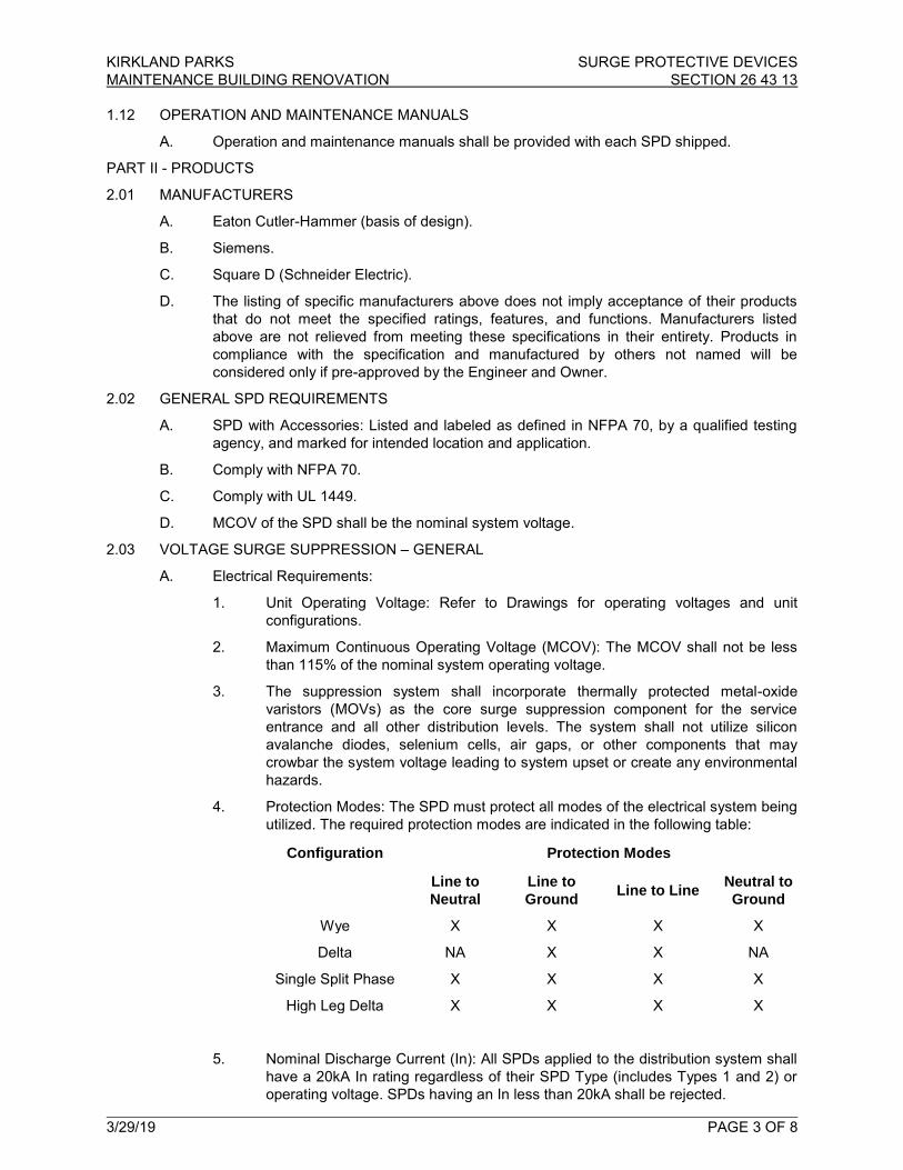
KIRKLAND PARKS SURGE PROTECTIVE DEVICES MAINTENANCE BUILDING RENOVATION SECTION 26 43 13
3/29/19 PAGE 3 OF 8
1.12 OPERATION AND MAINTENANCE MANUALS
A. Operation and maintenance manuals shall be provided with each SPD shipped.
PART II - PRODUCTS
2.01 MANUFACTURERS
A. Eaton Cutler-Hammer (basis of design).
B. Siemens.
C. Square D (Schneider Electric).
D. The listing of specific manufacturers above does not imply acceptance of their products that do not meet the specified ratings, features, and functions. Manufacturers listed above are not relieved from meeting these specifications in their entirety. Products in compliance with the specification and manufactured by others not named will be considered only if pre-approved by the Engineer and Owner.
2.02 GENERAL SPD REQUIREMENTS
A. SPD with Accessories: Listed and labeled as defined in NFPA 70, by a qualified testing agency, and marked for intended location and application.
B. Comply with NFPA 70.
C. Comply with UL 1449.
D. MCOV of the SPD shall be the nominal system voltage.
2.03 VOLTAGE SURGE SUPPRESSION – GENERAL
A. Electrical Requirements:
1. Unit Operating Voltage: Refer to Drawings for operating voltages and unit configurations.
2. Maximum Continuous Operating Voltage (MCOV): The MCOV shall not be less than 115% of the nominal system operating voltage.
3. The suppression system shall incorporate thermally protected metal-oxide varistors (MOVs) as the core surge suppression component for the service entrance and all other distribution levels. The system shall not utilize silicon avalanche diodes, selenium cells, air gaps, or other components that may crowbar the system voltage leading to system upset or create any environmental hazards.
4. Protection Modes: The SPD must protect all modes of the electrical system being utilized. The required protection modes are indicated in the following table:
Configuration Protection Modes
Line to Neutral
Line to Ground Line to Line Neutral to
Ground
Wye X X X X
Delta NA X X NA
Single Split Phase X X X X
High Leg Delta X X X X
5. Nominal Discharge Current (In): All SPDs applied to the distribution system shall have a 20kA In rating regardless of their SPD Type (includes Types 1 and 2) or operating voltage. SPDs having an In less than 20kA shall be rejected.

KIRKLAND PARKS SURGE PROTECTIVE DEVICES MAINTENANCE BUILDING RENOVATION SECTION 26 43 13
3/29/19 PAGE 4 OF 8
6. The maximum ANSI/UL 1449 3rd Edition Voltage Protection Rating (VPR) for the device shall not exceed the following:
Modes 208Y/120 Volts 480Y/277 Volts
L-N; L-G; N-G 700 1200
Line to Line 1200 2000
B. SPD Design:
1. Maintenance Free Design: The SPD shall be maintenance free and shall not require any user intervention throughout its life. SPDs containing items such as replaceable modules, replaceable fuses, or replaceable batteries shall not be accepted. SPDs requiring any maintenance of any sort such as periodic tightening of connections shall not be accepted. SPDs requiring user intervention to test the unit via a diagnostic test kit or similar device shall not be accepted.
2. Balanced Suppression Platform: The surge current shall be equally distributed to all MOV components to ensure equal stressing and maximum performance. The surge suppression platform must provide equal impedance paths to each matched MOV. Designs incorporating replaceable SPD modules shall not be accepted.
3. Electrical Noise Filter: Each unit shall include a high-performance EMI/RFI noise rejection filter. Noise attenuation for electric line noise shall be up to 50 dB from 10 kHz to 100 MHz using the MIL-STD-220A insertion loss test method. Products unable to meet this specification requirement shall not be accepted.
4. Internal Connections: No plug-in component modules or printed circuit boards shall be used as surge current conductors. All internal components shall be soldered, hardwired with connections utilizing low impedance conductors.
5. Monitoring Diagnostics: Each SPD shall provide the following integral monitoring options:
a. Protection Status Indicators: Each unit shall have a green/red solid-state indicator light that reports the status of the protection on each phase.
1) For wye configured units, the indicator lights must report the status of all protection elements and circuitry in the L-N and L-G modes. Wye configured units shall also contain an additional green/red solid-state indicator light that reports the status of the protection elements and circuitry in the N-G mode. SPDs that indicate only the status of the L-N and L-G modes shall not be accepted.
2) For delta configured units, the indicator lights must report the status of all protection elements and circuitry in the L-G and L-L modes.
3) The absence of a green light and the presence of a red light shall indicate that damage has occurred on the respective phase or mode. All protection status indicators must indicate the actual status of the protection on each phase or mode. If power is removed from any one phase, the indicator lights must continue to indicate the status of the protection on all other phases and protection modes. Diagnostics packages that simply indicate whether power is present on a particular phase shall not be accepted.
KIRKLAND PARKS SURGE PROTECTIVE DEVICES MAINTENANCE BUILDING RENOVATION SECTION 26 43 13
3/29/19 PAGE 5 OF 8
b. Remote Status Monitor: The SPD must include Form C dry contacts (one NO and one NC) for remote annunciation of its status. Both the NO and NC contacts shall change state under any fault condition.
c. Audible Alarm and Silence Button: The SPD shall contain an audible alarm that will be activated under any fault condition. There shall also be an audible alarm silence button used to silence the audible alarm after it has been activated.
d. Surge Counter: The SPD shall be equipped with an LCD display that indicates to the user how many surges have occurred at the location. The surge counter shall trigger each time a surge event with a peak current magnitude of a minimum of 50 +/- 20A occurs. A reset pushbutton shall also be standard, allowing the surge counter to be zeroed. The reset button shall contain a mechanism to prevent accidental resetting of the counter via a single, short-duration button press. In order to prevent accidental resetting, the surge counter reset button shall be depressed for a minimum of 2-seconds in order to clear the surge count total.
1) The ongoing surge count shall be stored in non-volatile memory. If power to the SPD is completely interrupted, the ongoing count indicated on the surge counter’s display prior to the interruption shall be stored in non-volatile memory and displayed after power is restored. The surge counter’s memory shall not require a backup battery in order to achieve this functionality.
6. Overcurrent Protection:
a. The unit shall contain thermally protected MOVs. These thermally protected MOVs shall have a thermal protection element packaged together with the MOV in order to achieve overcurrent protection of the MOV. The thermal protection element shall disconnect the MOV(s) from the system in a fail-safe manner should a condition occur that would cause them to enter a thermal runaway condition.
7. Fully Integrated Component Design: All of the SPD’s components and diagnostics shall be contained within one discrete assembly. SPDs or individual SPD modules that must be ganged together in order to achieve higher surge current ratings or other functionality shall not be accepted.
8. Safety Requirements:
a. The SPD shall minimize potential arc flash hazards by containing no user serviceable / replaceable parts and shall be maintenance free. SPDs containing items such as replaceable modules, replaceable fuses, or replaceable batteries shall not be accepted. SPDs requiring any maintenance of any sort such as periodic tightening of connections shall not be accepted. SPDs requiring user intervention to test the unit via a diagnostic test kit or similar device shall not be accepted.
b. SPDs designed to interface with the electrical assembly via conductors shall require no user contact with the inside of the unit. Such units shall have any required conductors be factory installed.
c. SPDs shall be factory sealed in order to prevent access to the inside of the unit. Side mount SPDs shall have factory installed phase, neutral, ground, and remote status contact conductors factory installed and shall have an 18-inch pigtail of conductors protruding outside of the enclosure for field installation.

KIRKLAND PARKS SURGE PROTECTIVE DEVICES MAINTENANCE BUILDING RENOVATION SECTION 26 43 13
3/29/19 PAGE 6 OF 8
2.04 SYSTEM APPLICATION
A. The SPD applications covered under this Section include distribution and branch panels, switchgear, and switchboard assemblies. All SPDs shall be tested and demonstrate suitability for application within ANSI/IEEE C62.41 Category A, B, and C environments.
B. Surge Current Capacity: The minimum surge capacity the device is capable of withstanding shall be as shown in the following table:
Category Application Per Phase Per Mode
A Branch Panelboard Locations 120 kA 60 kA
C. SPD Type: All SPDs installed on the line side of the service entrance disconnect shall be Type 1 SPDs. All SPDs installed on the load side of the service entrance disconnect shall be Type 1 or Type 2 SPDs.
2.05 LIGHTING AND DISTRIBUTION PANELBOARD REQUIREMENTS
A. The SPD application covered under this Section includes lighting and distribution panelboards. The SPD units shall be tested and demonstrate suitability for application within ANSI/IEEE C62.41 Category B environments.
1. The SPD shall not limit the use of through-feed lugs, sub-feed lugs, and sub-feed breaker options.
2. SPDs shall be installed immediately following the load side of the main breaker. SPDs installed in main lug only panelboards shall be installed immediately following the incoming lugs.
3. The panelboard shall be capable of re-energizing upon removal of SPD.
4. The SPD shall be interfaced to the panelboard via a direct bus bar connection. Where shown on the Drawings, an SPD connected to a 30 amp circuit breaker for disconnecting purposes may be installed using short lengths of conductors as long as the conductors originate integrally to the SPD. The SPD shall be located directly adjacent to the 30 amp circuit breaker.
5. The SPD shall be included and mounted within the panelboard by the manufacturer of the panelboard.
6. The SPD shall be of the same manufacturer as the panelboard.
7. The complete panelboard, including the SPD, shall be UL 67 listed.
8. Mounting Application Installation (SPD mounted external to the electrical assembly):
a. Lead length between the breaker and suppressor shall be kept as short as possible to ensure the optimum performance. Any excess conductor length shall be trimmed in order to minimize let-through voltage. The installer shall comply with the manufacturer’s recommended installation and wiring practices.
B. SPDs: Comply with UL 1449, Type 1:
1. Include LED indicator lights for power and protection status.
2. Internal thermal protection that disconnects the SPD before damaging internal suppressor components.
3. Include Form-C contacts rated at 5 A at 250 VAC, one normally open and one normally closed, for remote monitoring of protection status. Contacts shall reverse on failure of any surge diversion module or on opening of any current-limiting device. Coordinate with building power monitoring and control system.

KIRKLAND PARKS SURGE PROTECTIVE DEVICES MAINTENANCE BUILDING RENOVATION SECTION 26 43 13
3/29/19 PAGE 7 OF 8
C. Peak Surge Current Rating: The minimum single-pulse surge current withstand rating per phase shall not be less than 100 kA. The peak surge current rating shall be the arithmetic sum of the ratings of the individual MOVs in a given mode.
D. Comply with UL 1283.
E. Protection modes and UL 1449 VPR for grounded wye circuits with 480Y/277V and 208Y/120V, three-phase, four-wire circuits, shall not exceed the following:
Type 480Y/277V 208Y/120V
Line to Neutral 1200 Volts 700 Volts
Line to Ground 1200 Volts 700 Volts
Neutral to Ground 1200 Volts 700 Volts
Line to Line 2000 Volts 1200 Volts
F. SCCR: Equal to or exceeds 100 kA.
G. Inominal Rating: 20 kA.
2.06 ENCLOSURES
A. All enclosed equipment shall have NEMA 1 general purpose enclosures, unless otherwise noted. Provide enclosures suitable for locations as indicated on the Drawings and as described below:
1. Interior – NEMA 1: Constructed of a polymer (units integrated within electrical assemblies) or steel (side mount units only), intended for indoor use to provide a degree of protection against the ingress of solid foreign objects (falling dirt).
2.07 CONDUCTORS AND CABLES
A. Power Wiring: Same size as SPD leads, complying with Section 26 05 19 “Low-Voltage Electrical Power Conductors and Cables”.
PART III - EXECUTION
3.01 INSTALLATION
A. Comply with NECA 1.
B. The Contractor shall install all equipment per the manufacturer’s recommendations and the Contract Drawings.
C. Install an OCPD or disconnect as required to comply with the UL Listing of the SPD.
D. Install SPDs with the conductors between the suppressor and points of attachment as short and straight as possible, and adjust circuit-breaker positions to achieve shortest and straightest leads. Do not splice and extend SPD leads unless specifically permitted by the manufacturer. Do not exceed manufacturer’s recommended lead length. Do not bond neutral to ground.
E. Use crimped connectors and splices only. Wire nuts are not acceptable.
F. Wiring:
1. Power Wiring: Comply with wiring methods in Section 26 05 19 “Low-Voltage Electrical Power Conductors and Cables”.
2. Control Wiring: Comply with wiring methods in Section 26 05 19 “Low-Voltage Electrical Power Conductors and Cables”.
3.02 FACTORY TESTING
A. Standard factory tests shall be performed on the equipment under this Section. All tests shall be in accordance with the latest versions of NEMA and UL Standards.
KIRKLAND PARKS SURGE PROTECTIVE DEVICES MAINTENANCE BUILDING RENOVATION SECTION 26 43 13
3/29/19 PAGE 8 OF 8
3.03 FIELD QUALITY CONTROL
A. Perform the following tests and inspections with the assistance of a factory-authorized service representative.
1. Compare equipment nameplate data for compliance with Drawings and Specifications.
2. Inspect anchorage, alignment, grounding, and clearances.
3. Verify that electrical wiring installation complies with manufacturer’s written installation requirements.
B. An SPD will be considered defective if it does not pass tests and inspections.
C. Prepare test and inspection reports.
3.04 STARTUP SERVICE
A. Complete startup checks according to manufacturer’s written instructions.
B. Do not perform insulation-resistance tests of distribution wiring equipment with SPDs installed. Disconnect SPDs before conducting insulation-resistance tests, and reconnect them immediately after the testing is over.
C. Energize SPDs after the power system has been energized, stabilized, and tested.
3.05 GROUNDING
A. Train Owner’s maintenance personnel to operate and maintain SPDs.
***** END OF SECTION 26 43 13*****

KIRKLAND PARKS LIGHTING MAINTENANCE BUILDING RENOVATION SECTION 26 50 00
3/29/19 PAGE 1 OF 9
PART I - GENERAL
1.01 GENERAL
A. Conform to General Conditions, Supplementary Conditions, Division 01, and Division 26.
B. Review the Specifications and Drawings for coordination with additional requirements and information that apply to work under this Specification.
1.02 SUMMARY
A. Provide complete and operational lighting system including all fixtures, poles, lamps, hardware, mounting hardware including structural and pendant cable supports, installation appurtenances, wiring, and connections as required.
1.03 RELATED SECTIONS
A. Section 26 05 26 “Grounding and Bonding”.
B. Section 26 05 33 “Raceways and Boxes for Electrical Systems”.
C. Section 26 09 23 “Lighting Control System”.
D. Section 26 27 26 “Wiring Devices”.
1.04 REFERENCES
A. ANSI C82.4 – American National Standard for Ballasts for High-Intensity-Discharge Lamps (Multiple-Supply Type); 2002.
B. NECA 1 – Standard for Good Workmanship in Electrical Contracting; National Electrical Contractors Association; 2006.
C. NECA/IESNA 500 – Standard for Installing Indoor Commercial Lighting Systems; National Electrical Contractors Association; 2006.
D. NECA/IESNA 502 – Standard for Installing Industrial Lighting Systems; National Electrical Contractors Association; 2006.
E. NFPA 70 – National Electrical Code; National Fire Protection Association; Most Recent Edition Adopted by Authority Having Jurisdiction, Including All Applicable Amendments and Supplements.
F. NFPA 101 – Code for Safety to Life from Fire in Buildings and Structures; National Fire Protection Association; 2009.
G. UL 924 – Emergency Lighting and Power Equipment; Current Edition, Including All Revisions.
H. UL 1598 – Luminaires; Current Edition, Including All Revisions.
I. UL 8750 – Light Emitting Diode (LED) Equipment for Use in Lighting Products; Current Edition, Including All Revisions.
J. Institute of Electrical and Electronics Engineers (IEEE).
1.05 SUBMITTALS
A. Provide complete and operational lighting system including all fixtures, lamps, hardware, installation appurtenances, wiring, and connections as required.
B. Provide manufacturer’s standard catalog pages and data sheets including detailed information on luminaire construction, dimensions, ratings, finishes, mounting requirements, listings, service conditions, photometric performance, installed accessories, and ceiling compatibility; include model number nomenclature clearly marked with all proposed features.
C. Field quality control reports.

KIRKLAND PARKS LIGHTING MAINTENANCE BUILDING RENOVATION SECTION 26 50 00
3/29/19 PAGE 2 OF 9
D. Manufacturer’s Installation Instructions: Indicate application conditions and limitations of use stipulated by product testing agency. Include instructions for storage, handling, protection, examination, preparation, and installation of product.
E. Operation and Maintenance Data: Instructions for each product including information on replacement parts.
F. Maintenance Materials: Furnish the following for Owner’s use in maintenance of Project:
1. Extra Lenses and Louvers: Two percent of total quantity installed for each type, but not less than one of each type.
2. Extra Lamps: Ten percent of total quantity installed for each type, but not less than two of each type.
3. Extra Ballasts/Drivers: Two percent of total quantity installed for each type, but not less than one of each type.
1.06 QUALITY ASSURANCE
A. Conform to requirements of NFPA 70.
B. Manufacturer Qualifications: Company specializing in manufacturing the products specified in this section with minimum three years documented experience.
1.07 WARRANTY
A. Provide two year manufacturer warranty for all linear fluorescent ballasts.
B. Provide ten year pro-rata warranty for batteries for self-powered exit signs.
C. Provide five year manufacturer warranty for all LED power supplies.
D. Provide 50,000 hour lamp life on all LED modules.
PART II - PRODUCTS
2.01 MANUFACTURERS
A. Luminaires: Refer to Light Fixture Schedule in Drawings.
2.02 LUMINAIRES
A. Provide products that comply with requirements of NFPA 70.
B. Provide products that are listed and labeled as complying with UL 1598, where applicable.
C. Provide products listed and classified by Underwriters Laboratories Inc. as suitable for the purpose specified and indicated.
D. Unless otherwise indicated, provide complete luminaires including lamp(s) and all sockets, ballasts, reflectors, lenses, housings and other components required to position, energize and protect the lamp and distribute the light.
E. Unless specifically indicated to be excluded, provide all required conduit, boxes, wiring, connectors, hardware, supports, trims, accessories, etc. as necessary for a complete operating system.
F. Provide products suitable to withstand normal handling, installation, and service without any damage, distortion, corrosion, fading, discoloring, etc.
G. LED Luminaires: Listed and labeled as complying with UL 8750.
H. Luminaires Mounted in Continuous Rows: Provide quantity of units required for length indicated, with all accessories required for joining and aligning.

KIRKLAND PARKS LIGHTING MAINTENANCE BUILDING RENOVATION SECTION 26 50 00
3/29/19 PAGE 3 OF 9
I. Luminaires are to be manufactured or have their components assembled at the manufacturing plant for shipment. Include integrally mounted ballasts in the shipment from the fixture manufacturer where ballasts are required for the proper operation of the fixture lamps.
J. Unless noted otherwise, pendants and cord drop color shall be white, and cord drops are to be straight.
K. Provide accessories such as frames, stems, couplings, splice plates, cables, canopies, cords, toggle bolts, etc. necessary to install the fixture in the specific installation situation.
L. Pendant-mounted light fixtures shall have all supporting hardware furnished with the fixture tested in accordance with seismic support requirement Zone 4. Provide additional hanger wires and bracing for the support system above the ceiling.
2.03 LIGHT EMITTING DIODE (LED) FIXTURES
A. Housing: Rigid aluminum construction.
B. Finish: Visible surfaces. Powder coated paint or natural aluminum as specified in Light Fixture Schedule. Color and finish as selected by Architect. Concealed parts, (lamp holders, yokes, brackets, etc.) matte black.
C. Lamp Holder Housing: Cast aluminum with integral heat radiating fins to assure cool lamp base operation, with sufficient heat dissipation to meet device manufacturer's guidelines, certification programs, and test procedures for thermal management.
D. Off-State Power: Luminaires shall not draw power in the off state. Exception: Luminaires with integral occupancy, motion, photo-controls or individually addressable fixtures with external control and intelligence are exempt from this requirement. The power draw for such luminaires shall not exceed 0.5 watts when in the off state.
2.04 LED POWER SUPPLIES
A. Minimum Power Factor: 90%.
B. Minimum Operating Temperature: -20 degrees C.
C. Output Operating Frequency: 120 Hz minimum.
D. Power Supply:
1. Shall meet FCC requirements for non-consumer use.
2. Shall comply with IEEE C.62.41-1991, Class A operation.
E. Sound Rating: Class A.
2.05 LEDS
A. LED modules/arrays shall have a minimum CRI of 75 unless otherwise specified in the Light Fixture Schedule.
B. Color temperature variations shall not exceed +/- 100 degrees Kelvin at installation, and +/- 200 degrees Kelvin over the life of the module.
C. LED modules/arrays shall deliver at least 70% of initial lumens, when installed in-situ, for a minimum of 35,000 hours.
2.06 EXIT SIGNS
A. All Exit Signs: Internally illuminated with LEDs unless otherwise indicated; complying with NFPA 101 and all applicable state and local codes, and listed and labeled as complying with UL 924.
1. Number of Faces: Single or double as required for the installed location.
2. Directional Arrows: As required for the installed location.
KIRKLAND PARKS LIGHTING MAINTENANCE BUILDING RENOVATION SECTION 26 50 00
3/29/19 PAGE 4 OF 9
2.07 LAMPS
A. All Lamps:
1. Unless explicitly excluded, provide new, compatible, operable lamps in each luminaire.
2. Verify compatibility of specified lamps with luminaires to be installed. Where lamps are not specified, provide lamps per luminaire manufacturer's recommendations.
3. Minimum Efficiency: Provide lamps complying with all current applicable federal and state lamp efficiency standards.
4. Color Temperature Consistency: Unless otherwise indicated, for each type of lamp furnish products which are consistent in perceived color temperature. Replace lamps that are determined by the Owner's Representative to be inconsistent in perceived color temperature.
2.08 BALLASTS
A. Provide ballasts containing no polychlorinated biphenyls (PCBs).
B. Minimum Efficiency/Efficacy: Provide ballasts complying with all current applicable federal and state ballast efficiency/efficacy standards.
2.09 POLES
A. Furnish products as indicated in the Light Fixture Schedule in the Drawings.
B. All Poles: Provide poles, associated support components suitable for the luminaire(s), associated supports and accessories to be installed.
C. Pole Foundations:
1. Pre-cast concrete. Refer to Drawings.
2. Manufacturer’s: Oldcastle Precast, or reviewed and approved Manufacturers.
2.10 LIGHTING STANDARDS
A. Pole/Luminaire Assemblies and Bollards: Supply luminaires, davit arms, brackets, poles, handhole covers, base components and all other accessories for a complete assembly. Manufacturer shall be responsible for proper fitting of all elements and the structural integrity of the unit. Provide assembly to withstand 100 mph steady wind rated poles with 1.3 gust factor.
B. Provide watertight insulating fuse and holder in the base of each lighting standard to individually protect each lighting fixture. Fuse holder similar to Buss style "HEX" (HEB permitted for 120V or 277V), with Buss fuse of appropriate ampacity and voltage. Provide fuse for each hot circuit wire; do not fuse neutral.
PART III - EXECUTION
3.01 GENERAL
A. Comply with NEC 410.
B. Remove all tags, stickers, etc. from fixtures before installation.
3.02 EXAMINATION
A. Examine substrates, areas, and conditions, with Installer present, for compliance with requirements for installation tolerances and other conditions affecting performance of the Work.
B. Examine roughing-in for luminaire to verify actual locations of luminaire and electrical connections before luminaire installation.
KIRKLAND PARKS LIGHTING MAINTENANCE BUILDING RENOVATION SECTION 26 50 00
3/29/19 PAGE 5 OF 9
C. Proceed with installation only after unsatisfactory conditions have been corrected.
D. Verify that field measurements are as shown on the Drawings.
E. Verify that outlet boxes are installed in proper locations and at proper mounting heights and are properly sized to accommodate conductors in accordance with NFPA 70.
F. Verify that suitable support frames are installed where required.
G. Verify that branch circuit wiring installation is completed, tested, and ready for connection to luminaires.
H. Verify that conditions are satisfactory for installation prior to starting work.
3.03 WIRING
A. Pre-manufactured wiring systems are not acceptable.
B. Exit fixtures shall be connected to non-switched, emergency circuits.
3.04 LIGHTNIG FIXTURE SUPPORT
A. Fixture supports shall:
1. Provide support for all of the fixtures. Supports may be anchored to channels of the ceiling construction, to the structural slab or to structural members within a partition, or above a suspended ceiling.
2. Maintain the fixture positions after cleaning and re-lamping.
3. Support the lighting fixtures without causing the ceiling partition to deflect.
4. Hardware for recessed fixtures:
a. Where the suspended ceiling system is supported at the four corners of the fixture opening, hardware devices shall clamp the fixture to the ceiling structural members, or plaster frame at not less than four (4) points in such a manner as to resist the spreading of the support members and safely lock the fixture into the ceiling system.
b. Where the suspended ceiling system is not supported at the four (4) corners of the fixture opening, hardware devices shall independently support the fixture from the building structure at four (4) points.
c. All fixture mounting devices connecting fixtures to the ceiling system or building structure shall have a capacity for a horizontal force of 100-percent of the fixture weight and a vertical force of 400-percent of the fixture weight.
d. Mounting devices shall clamp the fixture to the ceiling system structure (main grid runners or fixture framing cross runners) at four (4) points in such a manner as to resist the spreading of these supporting members. Each support point device shall utilize a screw or approved hardware to “lock” the fixture housing to the ceiling system, restraining the fixtures from movement in any direction relative to the ceiling. The screw (size No. 10 minimum) or approved hardware shall pass through the ceiling member (T-bar, spline, or channel), or it may extend over the inside of the flange of the channel (or spline) that faces away from the fixture, in such a manner that prevents any fixture movement.
e. In addition to the above, provide the following for fixtures exceeding 20-lbs in weight:
KIRKLAND PARKS LIGHTING MAINTENANCE BUILDING RENOVATION SECTION 26 50 00
3/29/19 PAGE 6 OF 9
1) Where fixtures mounted in intermediate and heavy duty ceilings as per ASTM Standard C365, and weight between 20-lbs and 56-lbs, provide two (2) 12-gauge safety hangers hung slack between diagonal corners of the fixture and building structure.
2) Where fixtures weigh over 56-lbs, the fixtures shall be independently supported from the building structure by approved hangers. Two-way angular bracing of hangers shall be provided to prevent lateral motion.
f. Where ceiling cross runners are installed for support of lighting fixtures, they must have a carrying capacity equal to that of the main ceiling runners and be rigidly secured to the main runners.
5. Hardware for surface mounting fixtures to suspended ceilings:
a. In addition to being secured to any required outlet box, fixtures shall be bolted to a grid ceiling system at four points spaced near the corners of each fixture. The bolts shall not be less than 1/4-inch secured to channel members attached to and spanning the tops of the ceiling structural grid members or spanning channels by special clips designed for the purpose, provided they lock into place and require simple tools for removal.
b. In addition to being secured to any required outlet box, fixtures shall be bolted to ceiling structural members at four (4) points spaced near the corners of each fixture. Pre-positioned 1/4-inch studs or threaded plaster inserts secured to ceiling structural members shall be used to bolt the fixtures to the ceiling. In lieu of the above, 1/4-inch toggle bolts may be used on new or existing ceilings provided the plaster and lath can ssafely support the fixtures without sagging or cracking.
6. Surface mounted fixtures:
a. Fixtures shall be bolted against the ceiling independent of the outlet box at four (4) points spaced near the corners of each unit. The bolts (or stud-clips) shall be minimum 1/4-inch bolt, secured to main ceiling runners and/or secured to cross runners. Non-turning studs may be attached to the main ceiling runners and cross runners with special non-friction clip devices designed for the purpose, provided they bolt through the runner, or are also secured to the building structure by 12-gauge safety hangers. Studs or bolts securing fixtures weighing in excess of 56-lbs shall be supported directly from the building structure.
b. Where ceiling cross runners are installed for support of lighting fixtures, they must have a carrying capacity equal to that of the main ceiling runners and be rigidly secured to the main runners.
c. Fixtures less than 15-lbs in weight and occupying less than two (2) square-feet of ceiling area may, when designed for the purpose, be supported directly from the outlet box when all of the following conditions are met:
1) Screws attaching the fixture to the outlet box pass through round holes (not key-hole slots) in the fixture body.
2) The outlet box is attached to a main ceiling runner (or cross runner) with approved hardware.
3) The outlet box is supported vertically from the building structure.
KIRKLAND PARKS LIGHTING MAINTENANCE BUILDING RENOVATION SECTION 26 50 00
3/29/19 PAGE 7 OF 9
d. Fixtures mounted in open construction shall be secured directly to the building structure with approved bolting and clamping devices.
7. Single or multiple pendant-mounted fixtures:
a. Each stem or cable shall be supported by an approved outlet box mounted swivel joint and canopy which holds the stem or cable captive and provides spring load (or approved equivalent) dampening of fixture oscillations. Outlet box(es) shall be supported vertically from the building structure.
8. Outlet boxes for support of fixtures (where permitted):
a. Shall be secured directly to the building structure with approved devices or supported vertically in a hung ceiling from the building structure with a nine (9) gauge wire hanger, and be secured by an approved device to a main ceiling runner or cross runner to prevent any horizontal movement relative to the ceiling.
9. Manufacturer’s: Oldcastle Precast, or reviewed and approved Manufacturers.
3.05 INSTALLATION
A. Comply with NECA 1.
B. Coordinate locations of outlet boxes provided under Section 26 05 33 “Raceways and Boxes for Electrical Systems” as required for installation of luminaires provided under this section.
C. Install products according to manufacturer's instructions.
D. Install luminaires securely, in a neat and workmanlike manner, as specified in NECA and IESNA.
E. Install luminaires plumb and square and aligned with building lines and with adjacent luminaires.
F. Supports:
1. Sized and rated for luminaire weight.
2. Able to maintain luminaire position after cleaning and relamping.
3. Provide support for luminaire without causing deflection of ceiling or wall.
4. Luminaire-mounting devices shall be capable of supporting a horizontal force of 100 percent of luminaire weight and a vertical force of 400 percent of luminaire weight.
G. Flush-Mounted Luminaires:
1. Secured to outlet box.
2. Attached to ceiling structural members at four points equally spaced around circumference of luminaire.
3. Trim ring flush with finished surface.
H. Wall-Mounted Luminaires:
1. Attached to structural members in walls.
2. Do not attach luminaires directly to gypsum board.
I. Suspended Luminaires:
1. Ceiling mounted.
2. Pendants and Rods: Where longer than 48 inches, brace to limit swinging.

KIRKLAND PARKS LIGHTING MAINTENANCE BUILDING RENOVATION SECTION 26 50 00
3/29/19 PAGE 8 OF 9
3. Stem-Mounted, Single-Unit Luminaires: Suspend with twin-stem hangers. Support with approved outlet box and accessories that hold stem and provide damping of luminaire oscillations. Support outlet box vertically to building structure using approved devices.
4. Continuous Rows of Luminaires: Use tubing or stem for wiring at one point and wire support for suspension for each unit length of luminaire chassis, including one at each end.
5. Do not use ceiling grid as support for pendant luminaires. Connect support wires or rods to building structure.
J. Ceiling-Grid-Mounted Luminaires:
1. Secure to any required outlet box.
2. Secure luminaire to the luminaire opening using approved fasteners in a minimum of four locations, spaced near corners of luminaire.
3. Use approved devices and support components to connect luminaire to ceiling grid and building structure in a minimum of four locations, spaced near corners of luminaire.
K. Install accessories furnished with each luminaire.
L. Bond products and metal accessories to branch circuit equipment grounding conductor.
M. Install lamps in each luminaire.
3.06 IDENTIFICATION
A. Identify system components, wiring, cabling, and terminals. Comply with requirements for identification specified in Section 26 05 53 “Identification for Electrical Systems”.
3.07 FIELD QUALITY CONTROL
A. Inspect each product for damage and defects.
B. Operate each luminaire after installation and connection to verify proper operation.
C. Correct wiring deficiencies and repair or replace damaged or defective products at no additional cost to the Owner.
D. Repair or replace excessively noisy ballasts as determined by the Owner’s Representative at no additional cost to the Owner.
E. Repair or replace improperly functioning lamps or ballasts as determined by the Owner’s Representative at no additional cost to the Owner.
F. Perform the following tests and inspections:
1. Operational Test: After installing luminaires, switches, and accessories, and after electrical circuitry has been energized, test units to confirm proper operation.
2. Test for Emergency Lighting: Interrupt power supply to demonstrate proper operation. Verify transfer from normal power to battery power and then retransfer to normal power.
G. Luminaires will be considered defective if they do not pass operation tests and inspections.
H. Prepare test and inspection reports.
3.08 STARTUP SERVICE
A. Comply with requirements for startup as specified in Section 26 09 23 “Lighting Control System”.
KIRKLAND PARKS LIGHTING MAINTENANCE BUILDING RENOVATION SECTION 26 50 00
3/29/19 PAGE 9 OF 9
3.09 ADJUSTING
A. Occupancy Adjustments: When requested within 12 months of date of Substantial Completion, provide on-site assistance in adjusting the direction of aim of luminaires to suit occupied conditions. Make up to two visits to Project during other-than-normal hours for this purpose. Some of this work may be required during hours of darkness.
1. During adjustment visits, inspect all luminaires. Replace lamps or luminaires that are defective.
2. Parts and supplies shall be manufacturer’s authorized replacement parts and supplies.
3. Adjust the aim of luminaires in the presence of the Architect.
3.10 CLEANING
A. Clean surfaces according to NECA/IESNA and manufacturer's instructions to remove dirt, fingerprints, paint, or other foreign material and restore finishes to match original factory finish.
3.11 CLOSEOUT ACTIVITIES
A. Demonstrate proper operation of luminaires to Owner’s Representative, and correct deficiencies or make adjustments as directed. Coordinate this demonstration to be at same time as Lighting Control System programming and demonstration. Refer to Section 26 09 23 “Lighting Control System”.
B. Replace all lamps, ballasts, modules, etc. that have failed just prior to Substantial Completion.
3.12 COMMISSIONING REQUIREMENTS
A. The equipment and systems referenced in this Section are to be tested and commissioned per Section 01 52 00 “Inspections and Testing Services” and per Section 26 08 00 “Commissioning of Electrical Systems”. The Contractor has specific responsibilities for scheduling, coordination, startup, test development, testing and documentation. Coordinate all commissioning activities with the Commissioning Authority.
***** END OF SECTION 26 50 00*****


KIRKLAND PARKS TELECOMMUNICATIONS SYSTEM MAINTENANCE BUILDING RENOVATION SECTION 27 10 00
3/29/19 PAGE 1 OF 5
PART I - GENERAL
1.01 SCOPE
A. Provide complete and comprehensive cabling and termination for local area networks.
1.02 WORK INCLUDED
A. The work includes all necessary labor, installation, preparation, materials, equipment, services, and other items required, whether specified or not, to provide a complete and fully operational local area network cabling and jack system conforming to ANSI/TIA 568-D and ANSI/TIA-568-C.2 Category 6A.
B. The work requires installation of cabling, station jacks, patch cables, and patch panels, racks, cable tray, wire managers, 110 blocks, J-hooks, innerduct and other associated components.
C. The work includes performance of diagnostic tests on all cables, connectors and components. A signed written report of all diagnostic findings shall be provided to the Owner. Using the results of the diagnostic report, the Contractor is responsible for repairing all cable, connector and component problems.
D. The Telecommunications Contractor is to provide network cable to all systems as required. Category 6A cable to be provided, installed, terminated, and tested.
1.03 OWNER FURNISHED EQUIPMENT
A. All wiring switches, modules, computer equipment, file servers, workstations, network interface cards, and related hardware and software will be provided by the Owner.
B. No other equipment furnished.
1.04 DRAWINGS AND PLANS
A. All indicated data drop locations are to be cabled, including RJ45 jack at workstation end and termination and RJ45 jack at appropriate punch down blocks in head end rack.
1.05 PHYSICAL LAYER COMPONENTS
A. All components shall be new and shall comply with IEEE 802.3ab Standards for 1000-Base-T Ethernet over twisted pair media and ANSI/TIA Standard 568 (use most current revision). All components shall be housed in appropriate equipment racks so as to assure a solid, permanent installation. Bidder shall identify each proposed data system component by manufacturer and part number including data cabling, fiber optic cabling, data and data/phone jacks, UTP and fiber optic station and head end patch cables, patch panels, mounting devices for termination blocks, and equipment racks.
PART II - PRODUCTS
2.01 MATERIAL, COMPONENTS AND EQUIPMENT
A. All material, components, and equipment shall be new and of high quality. The components and equipment furnished must have a proven track record, and if required, the Contractor must furnish satisfactory evidence as to the kind and quality of materials and equipment. All work to comply with ANSI/TIA Category 6A requirements. Specification is based on products by Superior Essex/Ortronics no substitutes.
B. All telecom outlet back boxes shall be 5 square 2-7/8 inch deep. Provide T&B Steel City 82181T-1-114 or equal.
2.02 WARRANTY

KIRKLAND PARKS TELECOMMUNICATIONS SYSTEM MAINTENANCE BUILDING RENOVATION SECTION 27 10 00
3/29/19 PAGE 2 OF 5
A. Installer shall be certified by the manufacturer to provide the Ortronics CIP or CIP-ESP, nCompass™ Limited Lifetime static, Dynamic and applications warranty to the end user. The end user must also receive a Limited Lifetime product warranty. Refer to www.ncompass-systems.com or www.legrand.us for additional information on the nCompass warranty. Contractor shall provide electronic media for all above listed information.
2.03 TELECOMMUNICATIONS ROOMS AND SPACES
A. Fire Retardant Plywood Backboards:
1. Provide 3/4” x 8’ high fire retardant ACX plywood backboard to cover walls as shown on drawings. Backboard shall bear a seal identifying that plywood is fire-rated.
2. Backboard shall be finished with flat latex, white anti-static sealer or overcoat paint. Paint plywood backboard on all sides and edges prior to mounting on walls. Area around fire retardant seal shall be unpainted so that seal remains exposed and visible.
3. Backboard shall be mounted at +6-inches above finished floor.
4. Install plywood backboard in full sheets, C-side exposed, butting top edge of backboard to ceiling. Secure studs with screws nominally every 24-inches of vertical spacing.
2.04 TELECOM OUTLETS
A. ANSI/TIA 568-C Category 6A modular jacks. Provide inserts for number of data outlets shown on Drawings. Plate and outlets fog white color. Provide Ortronics OR-40300546 single gang faceplate and OR-TJ6A-99 Category 6A insert, provide yellow color icon for data and blue for voice, and label. Provide fog white blanks in unused outlets, Ortronics OR-42100002.
B. Where indicated on drawings, telecommunications modules shall share a common faceplate. All four pairs of the UTP cable shall be terminated on each RJ45 module.
C. Phone and data are same on this project.
D. Power Pole, Floor Box, or Poke-thru Pedestal Bezel:
1. Bezel types
a. Bezel shall hold a maximum of four RJ45 modules.
b. Bezels mounted in floor boxes and poke-thru pedestals shall be fog white in color.
c. Bezels mounted in power poles shall utilize a color that matches the power pole and shall utilize a 106-type configuration. Default color shall be Wiremold ivory.
d. Manufacturer is Ortronics:
1) 4-port 106–type bezel, Part No. OR-40800019-99
2) 4-port stylistics bezel, Part No. OR-41900018-99
E. T568B Type terminations.
F. Bend radius limitations must be adhered to inside the telecom outlet box. Service loops of 1-3’ should be worked into the ceiling for future use.
2.05 TELECOMMUNICATIONS HORIZONTAL CABLE
A. ANSI/TIA 568-C, Category 6A, 4-pair 23-gauge. Superior Essex 10Gain white, non-plenum rated.
2.06 RACKS & CABINETS
KIRKLAND PARKS TELECOMMUNICATIONS SYSTEM MAINTENANCE BUILDING RENOVATION SECTION 27 10 00
3/29/19 PAGE 3 OF 5
A. Floor Rack: Provide 19”, 2-post floor rack, 7’ high. Provide shelves per details. Ortronics OR-MM6E710.
B. Power Strip Ortronics No. 60400681 provide one per rack.
C. Ortronics cable runway (black).
D. Horizontal Wire management Ortronics OR-808044855 for copper and OR-808044915 for fiber.
E. Vertical Wire Management Ortronics OR-MM6VML704.
F. Wall Mount Cabinet: Provide Ortronics Mighty Mo Wall Cabinet. 48”H x 24”W x 26”D black wall mount cabinet with plexiglas door, mounting rails, and integral fans. Cabinet part # Ortronics OR-MMW262426P-B. 26U Mounting rail part # OR-MMW26M12-B. Fan assembly part # OR-MMCFAN-4-50.
2.07 PATCH PANEL
A. ANSI/TIA 568-C Category 6A, ports as shown on Drawings, 110 on back, RJ45 on front. Ortronics #OR-PHD6AU48.
B. T568B Type terminations.
2.08 PATCH CABLE
A. Data: Ortronics #OR-MC6A, ANSI/TIA Category 6A, 4-pair, 23-gauge, lengths and colors as follows:
Data-White
3' 40
5' 40
7' 10
9' 10
2.09 FIBER OPTIC PATCH PANEL & CABLE
A. Fiber Optic Backbone Cable Laser Optimized 12-Strand Multi-Mode: Superior Essex # 43012NG01
B. Indoor/outdoor 12-Strand Multi-Mode fiber optic cable: Superior Essex # W4012NGYY.
C. Fiber Optic Patch Cord: LC on both ends. Provide (10) 1 meter, (10) 2 meter, and (10) 3 meter patch cords. Ortronics P1DF series.
D. Fiber Optic Patch Panel: Provide rack mounted interconnection unit with space for fibers. Provide panel adapters. All terminations in patch panels LC Type. Ortronics OR-FC02U-P with OR-OFP-LCD12AC adapter panels.
E. Innerduct: All fiber optic cables in plastic innerduct of size required for work or as noted on Drawings.
F. Fiber Optic Connectors; LC style connectors shall be reusable. The LC style connectors must be prepolished with low insertion loss. Ortronics # 205KNT9SA-09.
2.10 WRAPS AND SUPPORTS
A. Provide J-hooks, B-Line#BCH64, 4” with BCHR4 retainer clip or Cablofil #CJ64. J-Hooks and cable tray are only acceptable cable supports.
B. Tie wraps shall not be used. Provide Ortronics OR-7070084-00 Series Velcro wraps.
PART III - EXECUTION
3.01 EQUIPMENT MOUNTING
KIRKLAND PARKS TELECOMMUNICATIONS SYSTEM MAINTENANCE BUILDING RENOVATION SECTION 27 10 00
3/29/19 PAGE 4 OF 5
A. All equipment shall be suitable mounted on fire rated terminal backboards, in equipment racks, or otherwise suitably solidly supported. Equipment suspended by its cable or connector is unacceptable. Placing of equipment shall be done to insure that it is readily accessible.
3.02 CABLE INSTALLATION
A. Cable run layouts indicated on the Drawings are generally diagrammatic. Exact routing of conduit and wiring shall be governed by the location of obstructions and building structural conditions. Cable runs shall be in cable trays, raceways, and above ceiling spaces as shown on Drawings.
B. All fiber cable runs shall have a minimum 20 times the outside diameter bending radius during installation and 10 times the outside diameter post installation.
C. All four pair copper cabling shall have a minimum bend radius of 4 times the outside diameter of the cabling.
D. Service loops are to be determined by the site manager or the associated drawings. All copper service loops shall be in a figure 8 configuration.
3.03 CABLE SUPPORTS
A. Cable shall be in raceway, either surface raceway, conduit, or cable tray or supported at 5' O.C. by J-hooks where open above ceilings. Wrap cable to perform a neat and professional installation. Cable wraps shall be loose to provide no strain on cables.
3.04 CABLE LABELS
A. All cables shall be permanently labeled at workstation jack, termination block and host module port to identify terminal location and on both ends of cable. Label designation shall be a continuation of the existing labeling scheme. Example: 1-1-6 = MDF-Patch Panel One-Port 6. Example: 2-1-6 = IDF-Patch Panel One- Port 6. Consult Owner for number sequence prior to submitting shop drawings.
3.05 DATA CABLE ROUTING
A. All shall be routed to prevent interference with any systems such as access boxed, ventilation mixing boxes, access hatches to air filters, switch panels, fire alarm equipment, lighting fixtures, etc. The routing must not interfere with any other service or system, operation or maintenance. Raceway shall not be placed in close contact with other devices, electrical or otherwise, that will interfere with its proper operation as a transmitter of data signal. The Contractor will be responsible for rerouting any raceway that is not acceptable to the Architect at no cost. Where surface raceways are used, care shall be taken to route around existing obstacles. Ceilings, wall trim shall be neatly cut to allow installation of surface raceways only as required at permission of the Owner. Cable fill rates must not exceed 75% of the maximum allowable fill to allow for future Moves, Adds and Changes. Bend radius entering and exiting the cable tray and J Hooks must be controlled to not exceed ANSI/TIA recommendations.
3.06 DATA STATION DROPS
A. All drop cables shall be installed at locations as indicated on Drawings. Exact outlet location within each room will be as indicated on the Drawings and will deviate from the drawing only by minimal shifting the outlet laterally along the indicated wall. The drop cabling shall be installed without splices from the outlets to the appropriate terminal block.
B. All copper and fiber cabling must be installed and terminated using the latest version of ANSI/TIA-568, ANSI/TIA-607-C, ANSI/TIA-569-D and BICSI TDMM Revision 13.
3.07 TESTING
KIRKLAND PARKS TELECOMMUNICATIONS SYSTEM MAINTENANCE BUILDING RENOVATION SECTION 27 10 00
3/29/19 PAGE 5 OF 5
A. The Contractor shall test all installed unshielded twisted pair cables, termination to termination to meet ANSI/TIA Category 6A Standards and Ortronics warranty requirements including wire map, length, attenuation, return loss, near end cross talk (NEXT), delay skew, Propagation Delay, PowerSum Near End Cross Talk (PSNEXT), Equal Level Far End Cross Talk (ELFEXT)and Power Sum equal level far end cross talk (PSELFEXT).
B. The end user shall receive the test results via a memory stick. Test results must be delivered in original tester format and pdf with all tests resulting in a PASS. Tests resulting in a marginal pass (*PASS) or Fail will not be acceptable. The end user can also request a printed report for their records.
3.08 COMPANY QUALIFICATIONS
A. The bidder shall be regularly engaged in the type of work specified herein. Award will be made only to a bidder who furnished satisfactory evidence that he has the technical ability, experience, equipment, personnel, and financial resources to enable him to successfully and promptly fulfill the requirements and conditions of these specifications.
B. Bidder must have an installation base of at least 150 workstation drops using proposed products.
3.09 FIBER OPTIC CABLE
A. Terminations: All strands shall be terminated and tested. Backboard, terminals, and patch panels shall be professionally configured, including but not limited to, cable cleats, wire harnesses, support rings, etc., and should be dressed and installed to provide a planned layout of the installation.
B. Cable: Install in inner duct and rack. Install in the Figure-8 method off the reel prior to pulling. No other practice is permitted. The maximum recommended bending radius shall not be exceeded. The maximum recommended permanent bend after installation shall not be exceeded.
C. Pulling locations must utilize a dynamometer. Maximum tensile load shall not exceed manufacturer’s recommendations. Install no LB’s on Fiber Optic conduit runs.
3.10 FIBER OPTIC CABLING TESTING
A. Test all cable and connections for continuity and repair all defects. Testing must be completed with an Optical Loss Test Set capable of testing single mode fiber to the application required by the Owner. Total loss budget for any fiber channel shall not exceed 2.6dB. Testing requirements must meet ANSI/TIA-526-14-C.
B. O.T.D.R. tests after the LC connectors are installed will be included for all strands and fiber optic power metering testing is required while on reel. Submit all test results to Architect.
C. Test per Ortronics and ANSI/TIA-568.D-3 testing requirements. The nCompass warranty requires bi-directional testing using both wavelengths. All testers must show a calibration within the 12 months prior to ensure accuracy. No Fail test results are allowed. The contractor must request a warranty from Ortronics shall be within 30 days of the project completion. Ortronics will issue a Limited Lifetime Static, Dynamic and Application Assurance channel warranty to the end user thru the contractor.
***** END OF SECTION 27 10 00*****


KIRKLAND PARKS ACCESS CONTROL SYSTEM MAINTENANCE BUILDING RENOVATION SECTION 28 13 00
3/29/19 PAGE 1 OF 9
PART I - GENERAL
1.01 DESCRIPTION
A. This section describes general requirements, products and methods of execution relating to the Access Control System (ACS) for the project.
B. The system shall be easy to use and fully user-programmable to allow the Owner to make all changes to the installed system. Vendor or Factory support shall not be required to make operational programming changes.
1.02 SCOPE
A. Provide in operating condition an electrically operated access control system as described herein. This system shall include but not limited to, an access control panel, software and all licensing, door contacts, card readers, proximity cards, back up batteries and shall support the connections, monitoring and reporting of the access control system. Provide all power supplies, conduit, wire, fittings and accessories required to provide a complete operating system. All units shall be located in accordance with the plans and as governed by the manufacturer’s installation guidelines.
B. The work covered by this Section of the Specifications includes the furnishing of all labor, equipment, materials, and performance of all operations in connection with the installation of the access control system as shown on the drawings and as herein specified. The requirements of the conditions of the Contract, Supplementary Conditions and General Requirements, apply to the work specified in this Section.
C. The work covered by this Section of the Specifications shall be coordinated with the related work as specified elsewhere under the project specifications.
D. Card access control system (system) basis of design is Genetec card access control system. The card reader controllers will be connected by network cabling. The IT room will have the main head end equipment.
E. Card reader located outside lobby that has security keypad will dis-alarm security system for building. Contractor to integrate the two systems together by providing all modules, devices, relays, and programming.
F. Any card reader that is in view of video surveillance camera will activate the recorder on for 10 minutes. Contractor to integrate the two systems together by providing all modules, devices, relays, and programming.
G. The system shall include a converter for Ethernet connection to the owner’s WAN/LAN.
1.03 RELATED REQUIREMENTS
A. Section 08 71 00 “Door Hardware”.
B. Section 26 05 00 “Common Work for Electrical Systems”.
C. Section 26 05 19 “Low-Voltage Electrical Power Conductors and Cables”.
D. Section 26 05 33 “Raceways and Boxes for Electrical Systems”.
E. Section 27 10 00 “Telecommunications System”.
F. Section 28 16 00 “Intrusion Detection”.
G. Section 28 31 00 “Fire Detection and Alarm”.
1.04 REFERENCES
A. ANSI/NFPA 70 – National Electrical Code.
B. NFPA 70E – Standard for Electrical Safety in the Workplace.
KIRKLAND PARKS ACCESS CONTROL SYSTEM MAINTENANCE BUILDING RENOVATION SECTION 28 13 00
3/29/19 PAGE 2 OF 9
C. TIA/EIA – Telecommunications Industry Association/Electronics Industries Alliance.
D. ASTM International.
1.05 GENERAL
A. The card access system shall be a powerful, flexible, multi-function and object oriented security and event management system that features a variety of customizable interfaces for maintaining the system and for monitoring the desired secure sites. The system shall provide an option to display these management and monitoring interfaces in the native languages of the people using the system. The security and event management system shall be flexible in order to meet specific requirements and quickly respond to evolving security challenges. The system shall be a scalable platform, simple and economical enough to support a single site, yet upgradeable enough to manage a multi-site network. The system shall use an open, distributed architecture, where database servers could reside in geographically separate locations.
B. The system shall provide extensive information management capability using Microsoft NET Framework V3.5. It shall operate in a client server configuration on personal computers with a Windows based platform. Its distributed client server architecture shall be capable of supporting up to (128) simultaneous clients, multiple types of controllers, and over (10,000) input devices, including cameras and multiple types of card readers. The system shall be constructed to be database independent and shall support at a minimum Microsoft SQL Server 2005 (Express, Standard, Data Center, or Enterprise), and Oracle 10g Databases for data protection, redundancy and manageability.
C. The system shall have true multi-tasking, multi-processor and remote client support; allowing independent activities and monitoring to occur simultaneously at different locations. The operator workstation (client) shall be user friendly, employing icon based menus and providing a mouse driven interface for system operation and the creation of color graphic maps. The user interface shall be customizable, capable of delivering a unique look and feel without a unique version release. It shall be an intuitive user interface that is similar to Microsoft’s Outlook and Explorer with its easy navigation and tree structures. A practical application layout editor shall let users drag and drop any application onto (1) screen and create a customized hub for all activities via a single “command and control” center.
D. Field devices such as card readers, alarm inputs, control points, etc. shall be connected to fully distributed intelligent field controllers or directly through a Software Development Kit or Web Services, and be capable of operating without host computer intervention. All objects within the system, i.e. doors, readers, time intervals, etc. shall be addressed by a unique name as opposed to point numbering or mnemonics. The system shall have badge generation tools to create and manage badges using a graphical interface and convenient query features to manage large numbers of badges.
1.06 TYPE OF SYSTEM
A. The Access Control System shall provide the following card access control operational objectives:
1. Controlled entry, via access card readers, of only authorized personnel to secured areas based on cardholder information entered and stored in the system data base.
2. The access request response time from card presentation, data base verification, to electric lock unlock shall be no more than one second in normal operating mode on a fully loaded system.

KIRKLAND PARKS ACCESS CONTROL SYSTEM MAINTENANCE BUILDING RENOVATION SECTION 28 13 00
3/29/19 PAGE 3 OF 9
3. All access requests, both authorized and denied, shall be sent to the host for storage and annunciation, as required, with the cardholder number, name, and access point/area where access was attempted or gained.
4. Each card and cardholder shall be entered into the database prior to their use. Each card can be manually disabled at any time without the requirement to delete the card. Each card can then be subsequently re-enabled at a later time.
5. Card records shall include the entry of activation and deactivation dates to provide for the automatic enabling and expiring of the card record.
6. The system shall provide the capability of setting a parameter of a number of days whereby cards will be automatically disabled if they are not used at all for access for that preset number of days (i.e. 30-days, 60-days, etc.). Any card can be subsequently re-enabled at any time.
7. The operating mode of access controlled doors shall be monitored as locked, unlocked, or controlled. The door status shall be monitored as open or closed.
8. The system shall provide for the monitoring of the reader controlled door position in order to detect and report Door Forced Open and Door Held Open alarm conditions. Door held condition shall be based on a user-adjustable time period. The act of opening the door shall initiate the door timer, and also cause the immediate reset of the door lock.
9. Each cardholder shall be specified with access authority to a combination of Security Areas, each security area comprised of one or more card reader controlled door. Up to eight Security Areas may be defined. Each individual security area designated as authorized to an individual cardholder shall include a time zone assignment for that specific area.
10. The system shall provide for the designation of certain calendar days to be holidays, with special access privileges and system activity to be specified for those days.
11. The system shall provide for a completely downloaded and distributed database such that access control decisions are made locally at the access controller and, in the event of the failure of the host computer or loss of communications to the host computer, the access control system shall continue to operate using full data base information for all cardholders including security areas’ authorizations, time zones, expiration dates of cards, holidays, etc. At no time after a card has been entered into the database of the file server and validated, shall the system fail to respond to an access request by a valid cardholder.
1.07 SYSTEM OPERATION
A. The system shall be comprised of the number of points shown on the drawings (246 points maximum). Each point shall consist of an appropriate sensor and an addressable module as specified in Section 2.3.
B. The system shall be armed, disarmed, reset, monitored and altered by the use of a remote 4-wire multi-plex keypad and shall be capable of supporting up to 7 (32) remote keypads (8 Supervised). The system shall provide "fail safe arming" preventing arming of the system if a zone has been violated or a door is ajar. It shall indicate which point is not ready for arming at the remote keypad. Additionally, the proximity card readers shall be capable of disarming the system on entry to the building and rearming the system on exiting the building. The arm / disarm status shall be shown by status lights at each door equipped with proximity readers. See plans for locations.
C. Actuation of any point shall cause the following to occur:
KIRKLAND PARKS ACCESS CONTROL SYSTEM MAINTENANCE BUILDING RENOVATION SECTION 28 13 00
3/29/19 PAGE 4 OF 9
1. Activate the built-in digital communicator, seize the protected premises telephone line and automatically report the alarm to a remote location.
2. Indicate the alarm condition at the remote keypad.
1.08 QUALITY ASSURANCE
A. The manufacturers of all hardware and software components employed in the system shall be established vendors to the access control / security monitoring industry for no less than 5-years and shall have successfully implemented at least (5) systems of similar size and complexity.
1.09 CONTRACTOR QUALIFICATIONS
A. The security system integrator shall have been regularly engaged in the installation and maintenance of integrated access control systems and have a proven track record with similar systems of the same size, scope, and complexity.
B. The security system integrator shall supply information attesting to the fact that their firm is an authorized product integrator certified with the system. A minimum of (1) technician shall be a factory certified installer.
C. The security system integrator shall supply information attesting to the fact that their installation and service technicians are competent factory trained and certified personnel capable of maintaining the system and providing reasonable service time.
D. The security system integrator shall provide a minimum of (3) references whose systems are of similar complexity and have been installed and maintained by the security system integrator in the last 5-years.
E. There shall be a local representative and factory authorized local service organization that shall carry a complete stock of parts and provide maintenance for these systems.
F. Contractor shall be location and be within 50-miles of project site.
G. Manufacturer’s Certified Vendor and Installer (vendor) shall be certified in Genetec Access Control System and Pelco Video Surveillance for at least 2-year of experience. Provide certifications in submittals.
H. Request for substitutions of equal for vendor and equipment must be received by the engineer in writing not later than 10-days prior to bid and will be evaluated and notes in the addenda for approved; refer to Division 01 for request for substitutions.
1.10 PRODUCT DATA
A. Prior to assembling or installing the system, the Contractor shall provide the following:
1. Complete product data and technical specification data sheets that include manufacturer’s data for all material and equipment, including terminal devices, local processors, computer equipment, access cards, and any other equipment provided as part of the system.
2. A system description, including analysis and calculations used in sizing equipment required by the system. The description shall show how the equipment shall operate as a system to meet the performance requirements of the system. The following information shall be supplied as a minimum:
a. Central processor configuration and memory size.
b. Description of site equipment and its configuration.
c. Protocol description.
d. Rigid disk system size and configuration.
KIRKLAND PARKS ACCESS CONTROL SYSTEM MAINTENANCE BUILDING RENOVATION SECTION 28 13 00
3/29/19 PAGE 5 OF 9
e. Backup / archive system size and configuration.
f. Startup operations.
g. System expansion capability and method of implementation.
h. System power requirements and UPS sizing.
i. A description of the operating system and application software.
j. Provide test matrix to follow the function and integration of each system to the card access control system.
1.11 SHOP DRAWINGS
A. Prior to assembling or installing the system, the Contractor shall provide complete shop drawings which include the following:
1. Architectural floor plans indicating all system device locations.
2. Full schematic wiring information for all devices. Wiring information shall include cable type, cable length, conductor routings, quantities, and point-to-point termination schedules.
3. Provide one (1) banana cabling to each card reader location with future spare wiring. Refer to system plans for locations.
4. Complete access control system 1-line block diagram.
5. Statement of the system sequence of operation.
6. Riser diagrams showing interconnections.
7. Detail drawings showing installation and mounting.
8. Fabrication drawings for console arrangements and equipment layout.
9. Provide a final testing matrix for each device and blank space for IP and MAC addresses.
B. All drawings shall be fully dimensioned and prepared in DWG format using any CAD based software capable of exporting the format (such as AutoCAD).
1.12 AS-BUILT DRAWINGS
A. At the conclusion of the project, the Contractor shall provide “as built” drawings. The “as built” drawings shall be a continuation of the Contractor’s shop drawings as modified, augmented, and reviewed during the installation, check out and acceptance phases of the project. All drawings shall be fully dimensioned and prepared in DWG format using any CAD based software capable of exporting the format (such as AutoCAD).
1.13 O&M MANUALS
A. At the conclusion of the project, the Contractor shall provide copies of the manuals as described herein. Each manual’s contents shall be identified on the cover. The manual shall include names, addresses, and telephone numbers of each security system integrator installing equipment and systems and the nearest service representatives for each item of equipment for each system. The manuals shall have a table of contents and labeled sections. The manuals shall include all modifications made during installation, checkout, and acceptance. The manuals shall contain the following:
1. Functional Design Manual

KIRKLAND PARKS ACCESS CONTROL SYSTEM MAINTENANCE BUILDING RENOVATION SECTION 28 13 00
3/29/19 PAGE 6 OF 9
a. The Functional Design Manual shall identify the operational requirements for the system and explain the theory of operation, design philosophy, and specific functions. A description of hardware and software functions, interfaces, and requirements shall be included for all system operating modes.
2. Hardware Manual
a. The Hardware Manual shall describe all equipment furnished including:
1) General description and specifications.
2) Installation and check out procedures.
3) Equipment layout and electrical schematics to the component level.
4) System layout drawings and schematics.
5) Alignment and calibration procedures.
6) Manufacturers repair parts list indicating sources of supply.
3. Software Manual
a. The Software Manual shall describe the functions of all software and shall include all other information necessary to enable proper loading, testing, and operation. The manual shall include:
1) Definition of terms and functions.
2) Use of system and applications software.
3) Initialization, startup, and shut down.
4) Alarm reports.
5) Reports generation.
6) Data base format and data entry requirements.
7) Directory of all disk files.
4. Operators Manual
a. The Operator’s Manual shall fully explain all procedures and instructions for the operation of the system including:
1) Computers and peripherals.
2) System startup and shut down procedures.
3) Use of system, command, and applications software.
4) Recovery and restart procedures.
5) Graphic alarm presentation.
6) Use of report generator and generation of reports.
7) Data entry.
8) Operator commands.
9) Alarm messages and reprinting formats.
10) System access requirements.
5. Maintenance Manual
KIRKLAND PARKS ACCESS CONTROL SYSTEM MAINTENANCE BUILDING RENOVATION SECTION 28 13 00
3/29/19 PAGE 7 OF 9
a. The Maintenance Manual shall include descriptions of maintenance for all equipment including inspection, periodic preventive maintenance, fault diagnosis, and repair or replacement of defective components.
PART II - PRODUCTS
2.01 MANUFACTURERS
A. Access Control System equipment shall consist of a system assembled as an approved unit of regularly manufactured components, by a single manufacturer for the purposes described elsewhere in this specification. Interconnecting equipment that has not been listed for interconnection or the creation of components or system into a non-standard unit that is not normally available from the manufacturer is not acceptable.
B. Providing they meet all specifications, control panels and related equipment shall be manufactured by Genetec Access Control System basis of design for this project.
2.02 SMS SOFTWARE
A. Security Management System (SMS) Software: Genetec Synergis Software.
2.03 SMS FIELD HARDWARE
A. General Equipment Part List:
1. Head end Equipment: Provide in IT room. Genetec Part #SY-CLOUDLINK.
2. Head end Equipment: Provide all for Diagrams in Drawings.
3. Portals License: Provide licenses as required.
4. 2-Door Access Control Node: Provide one per every two reader’s locations on drawings. HID Part #V-100-0 or Equal.
5. Power Supply: Provide one per access control panel. LSP Part # FPO75, FPO250, D8P, NL2 as required or Equal. Power supplies shall be capable of supplying power to all associated electronics, card readers, and electric locks that are connected to each panel.
6. Card Readers: Provide one for every location on electrical plans. HID Part # 920PTNNEK0000 or Equal.
7. Cards: Provide 50 cards for this project.
8. Door Contact: Provide one for every card reader location on electrical plans. Sentrol Part #1078 Series or Equal.
9. REX : Provide one for every card reader location on electrical plans. Unless the door has free egress. Bosch Part #DS150i or Equal.
10. Electric door strike – Provide one for every card reader location on electrical plans. Provided, powered, and install by contractor. Coordinate provisions with door hardware contractor.
11. Battery: Provide batteries as required per installation manual. Minimum 8-hour battery backup. Provide battery backup calculations in submittals.
12. Access Control Contractor to provide enclosures as required.
2.04 CERTIFICATIONS
A. UL 294 listed.
B. ISO 9000 listed.
PART III - EXECUTION
KIRKLAND PARKS ACCESS CONTROL SYSTEM MAINTENANCE BUILDING RENOVATION SECTION 28 13 00
3/29/19 PAGE 8 OF 9
3.01 INSTALLATION
A. Provide all equipment, wiring, conduit and outlet boxes required for the installation of a complete and operating system in accordance with applicable local, state and national codes, the manufacturer's recommendations, these plans and specifications. All circuits not in conduit must be wired with UL listed power limited cable under NEC 725 Class-II wiring. Plenum cable shall be utilized in all return air plenum ceilings. All other types of wiring must be in a separate conduit system. Color coded wires shall be used throughout. Wiring shall conform to the National Electrical Code Article 725. Provide one (1) banana cabling to each card reader location with future spare wiring. Refer to system plans for locations.
B. All equipment and wiring shall be guaranteed against defects in materials and workmanship for a 1-year period from the startup and beneficial use of the system. Warranty service for the equipment shall be provided by the system supplier's factory trained representative during normal working hours, Monday through Friday, excluding Holidays. Emergency service provide at times other than as stipulated above shall be available from the same source at additional cost to the Owner.
C. Installation of equipment and devices that pertain to other work in the Contract shall be closely coordinated with the appropriate Subcontractors.
D. The Contractor shall clean all dirt and debris from the inside and the outside of the card access equipment after completion of the installation.
3.02 SUPERVISION
A. The manufacturer shall provide all on-site supervision of the installation, perform a complete functional test of the system and submit a written report to the Contractor attesting to the proper operation of the complete system.
3.03 PROGRAMMING
A. Programming of the system shall include the following tasks:
1. Creation of the local card database in the PC, including setting card access privileges as directed by the Commissioning Agent.
2. Programming all system configuration parameters.
3.04 TESTING
A. The completed card access system shall be fully tested by the Contractor in the presence on the Owner's representative. Upon completion of a successful test, the Contractor shall so certify in writing to the Owner and General Contractor.
B. Provide test matrix to follow the function and integration of each system to the card access control system.
C. Upon completion of the installation, and after test and demonstration, the Electrical Contractor shall provide the Architect a signed written Statement of Completion.
D. Provide a final testing matrix for each device with IP and MAC addresses.
3.05 INSTRUCTION
A. The equipment manufacturer shall provide, as part of this contract, a minimum of two training sessions for programming and operation training to the Building Owner.

KIRKLAND PARKS ACCESS CONTROL SYSTEM MAINTENANCE BUILDING RENOVATION SECTION 28 13 00
3/29/19 PAGE 9 OF 9
B. The manufacturer's representative shall conduct an instruction session during which all maintenance and operational aspects of the system will be described and demonstrated to personnel selected by the Owner. O&M Manual information regarding the system shall be turned over to the Architect prior to the scheduling of the training session. Provide one training session before final acceptance by NSD, after the system has been tested and inspected and after the Record Drawings and O&M Manuals have been completed and accepted. A second, follow-up training session shall be required 45-days after occupancy by the District. This session will go over staff questions and system operation confirmation.
3.06 WARRANTY
A. The Contractor shall warrant the completed security alarm system wiring and equipment to be free from inherent mechanical and electrical defects for a period of one 1-year from the date of the completed and certified test or from the date of first beneficial use.
B. The equipment manufacturer shall make available to the Owner a Maintenance Contract proposal to provide a minimum of two (2) inspections and test per year.
3.07 AS-BUILT DRAWINGS
A. As-built drawings shall be provided by the Electrical Contractor which clearly indicates:
1. Actual routing of all raceways.
2. Actual cable type, color, number, and routing.
3. Actual system wiring diagrams, connection diagrams and interface of all components in the system.
4. Add to as-built drawings device IP and MAC addresses.
***** END OF SECTION 28 13 00*****


KIRKLAND PARKS INTRUSION DETECTION MAINTENANCE BUILDING RENOVATION SECTION 28 16 00
3/29/19 PAGE 1 OF 7
PART I - GENERAL
1.01 SCOPE & RELATED DOCUMENTS
A. The work covered by this Section of the Specifications includes the furnishing of all labor, equipment, materials, and performance of all operations in connection with the installation of the security alarm system as shown on the drawings and as herein specified conform to General Conditions, Supplementary Conditions and Division 01.
B. The system shall be completely addressable and programmable.
C. The system shall be listed as a power limited device and be listed under the following performance standards. UL 1610 Central Station Burglar Alarm Units.
1. NFPA71 Central Station Signaling Systems.
2. NFPA72A Local Protective Signaling Systems.
3. NFPA72C Remote Station Protective Signaling Systems.
D. The work covered by this Section of the Specifications shall be coordinated with the related work as specified elsewhere under the project specifications.
E. Related Requirements:
1. Section 08 71 00 “Door Hardware”.
2. Section 26 05 00 “Common Work for Electrical Systems”.
3. Section 26 05 19 “Low-Voltage Electrical Power Conductors and Cables”.
4. Section 26 05 33 “Raceways and Boxes for Electrical Systems”.
5. Section 27 10 00 “Telecommunications System”.
6. Section 28 13 00 “Access Control System”
F. Project Scope: Provide a new security alarm control panel located in Electrical Room. Provide keypad in each area as follows, main lobby. Security system shall be armed or disarmed from any keypad and disarmed by Access Control Card Reader per area. Provide B426 Ethernet network model for monitoring, integration with Access Control, Lockdown, and Video Surveillance systems, and future connections to owner. Provide monitoring to central station for lockdown upon alarm. Provide all new components, power, conduits wiring as necessary.
1.02 SECTION INCLUDES
A. Interface with Access Control System.
B. Intrusion detection devices.
C. Alarm control panel.
D. Signaling devices.
1.03 SUBMITTALS
A. Prepare and submit shop drawings and catalog cut sheets for approval within the time period as stated in the General Conditions. Contractor shall not start any construction or order any materials prior to acceptance and approval of all submittals. Partial submittals are unacceptable. Submittals, as a minimum, shall include the following:
1. Product Data: Provide electrical characteristics and connection requirements.
2. Test Reports: Indicate satisfactory completion of required tests and inspections.

KIRKLAND PARKS INTRUSION DETECTION MAINTENANCE BUILDING RENOVATION SECTION 28 16 00
3/29/19 PAGE 2 OF 7
3. Manufacturer's Installation Instructions: Indicate application conditions and limitations of use stipulated by product testing agency. Include instructions for storage, handling, protection, examination, preparation, installation, and starting of product.
4. Project Record Documents: Record actual locations of initiating devices, signaling appliances, and end-of-line devices.
5. Operation Data: Operating instructions.
6. Maintenance Data: Maintenance and repair procedures.
7. The contractor shall provide current state and factory trained certificates of technicians assigned for this project.
1.04 SHOP DRAWINGS
A. Shop drawings for systems provided under this section of the specification shall contain but not be limited to the following:
1. Specification data sheets on each individual system component.
2. Wiring diagrams indicating all system components, number and size of required conductors, and interconnecting components.
3. Floor plan layout of devices, interconnecting wiring and point-to-point diagrams.
4. Provide a final testing and control matrix for each device.
5. Address point list.
6. Graphic Map with show the following all partitions, devices, points, panel, and keypads.
1.05 SYSTEM OPERATION
A. The system shall be comprised of the number of points shown on the drawings (246-points maximum). Each point shall consist of an appropriate sensor and an addressable module as specified in Section 2.1.
B. The system shall be armed, disarmed, reset, monitored and altered by the use of a remote 4-wire multiplex keypad and shall be capable of supporting up to 7 (32) remote keypads (8 supervised). The system shall provide "fail safe arming" preventing arming of the system if a zone has been violated or a door is ajar. It shall indicate which point is not ready for arming at the remote keypad.
1. Additionally, the proximity card readers shall be capable of disarming the system on entry to the building and rearming the system on exiting the building. The arm / disarm status shall be shown by status lights at each door equipped with proximity readers. See plans for locations.
C. Actuation of any point shall cause the following to occur:
1. Activate the built-in digital communicator, seize the protected premises telephone line and automatically report the alarm to a remote location.
2. Indicate the alarm condition at the remote keypad.
1.06 QUALITY ASSURANCE
A. Conform to requirements of NFPA 70.
KIRKLAND PARKS INTRUSION DETECTION MAINTENANCE BUILDING RENOVATION SECTION 28 16 00
3/29/19 PAGE 3 OF 7
B. These Specifications are based on equipment as supplied by Washington State Certified and Manufacturer’s Certified Vendor and Installer (vendor). Request for substitutions of equal for vendor and equipment must be received by the engineer in writing not later than 10-days prior to bid and will be evaluated and notes in the addenda for approved; refer to Division 01 for request for substitutions.
C. The system supplier shall be a company specializing in the manufacture and supply of security, fire and access control systems with at least 5-years of experience and shall have local employees available for support during installation and for final hook-up and acceptance testing. The local manufacturer’s office shall produce system specific layout and wiring shop drawings for use by the Installing Contractor.
D. Manufacturer’s Certified Vendor and Installer (vendor) shall be certified in Bosch Security and Genetec Access Control system for at least 2-year of experience. Provide certifications in submittals.
E. Security Alarm Contractor shall be location and be within 50-miles of project site.
PART II - PRODUCTS
2.01 MANUFACTURERS
A. Intrusion Detection System control equipment shall consist of a system assembled as an approved unit of regularly manufactured components, by a single manufacturer for the purposes described elsewhere in this specification. Interconnecting equipment that has not been listed for interconnection or the creation of components or system into a non-standard unit that is not normally available from the manufacturer is not acceptable.
B. Providing they meet all specifications, control panels and related equipment shall be manufactured by Bosch B9512G Security System.
2.02 ACCESS CONTROL and CCTV INTERFACES
A. Access Control and CCTV will be interfaced with security system by reader control module and security B426 network module. See Access Control System specification for more information. The card reader shall be compatible with current NSD access cards.
B. The card reader shall allow authorized users to arm and disarm the system zoned areas.
2.03 SECURITY CONTROL PANEL
A. Security control panel shall be Bosch B9512G current version. The security panel shall be listed by UL for Power Limited Circuits. Provide B426 network model for central station monitoring, D8125MUX MUX Expanders, and MUX Modules as required.
B. The system shall include the following features as a minimum:
1. Control Features
a. Eight programmable areas, each
b. with perimeter/interior partitioning, master, associate, and shared area operation.
c. Real time clock, test timer and up to 1000 event memory log (including date, time, event, point ID and User ID).
d. Battery charging circuit and voltage supervision, AC power supervision.
e. Automatic reset circuit protectors.
f. On-board CPU watchdog warning buzzer and diagnostic LEDs.
g. Lightning and EMI protection.
h. Power limited external circuits.

KIRKLAND PARKS INTRUSION DETECTION MAINTENANCE BUILDING RENOVATION SECTION 28 16 00
3/29/19 PAGE 4 OF 7
i. Built-in digital communicator with phone line monitor (loop or ground start).
j. Multiple telephone numbers, primary and duplicate paths with main and alternate destinations.
k. All reports within each routing group are programmable.
l. Optional dual phone line switcher monitors 2 phone lines.
m. Automatic test and status reports.
n. Time windows for arming and open/close report suppression.
o. Programmable answering machine work-around for remote programming on shared phone lines.
2. Programmable Outputs
a. 2V DC, 2 Amp alarm power.
b. 1.4 Amp Aux power.
c. 4 alarm output patterns.
d. Automatic bell test.
e. Programmable bell shut-off timer.
f. 131 programmable relay outputs.
g. Up to 3 parallel printers.
3. System Response
a. Eight on-board detection points, up to 238 off-board points for a total of 246 points.
b. 31 custom point responses, including fire supervisory.
c. Selectable loop response time.
d. Alarm verification.
e. Watch mode.
f. Scheduled events (Skeds) arm, disarm, bypass and un-bypass points, control relays and control authority levels.
4. User Interface
a. Supervise up to 8 command centers (up to 32 non-supervised command centers can be used).
b. Custom command center text.
c. Full function list, including up to 16 custom functions.
d. 250 users, each with authority by area and 16 character name.
e. Adjustable brightness/loudness for command center display/sounder.
2.04 KEYPAD
A. Provide keypads, Bosch B942W Touch Screen, where shown on the Drawings.
B. The keypad shall allow authorized users to arm and disarm the system zoned areas.
2.05 MOTION DETECTORS

KIRKLAND PARKS INTRUSION DETECTION MAINTENANCE BUILDING RENOVATION SECTION 28 16 00
3/29/19 PAGE 5 OF 7
A. Provide, as shown on Plans, UL listed Type-MUX835 combination microwave and passive infrared detector with B335-3 Mounting kit and built-in MUX module. Unit shall operate on 12 volts. Sensor shall offer wall or corner mounting. Sensor shall provide a 35’ x 35’ protection pattern.
B. Long range passive infrared motion detectors shall be provided where shown on the Plans. Detector shall be UL listed Type-MUX794Z combination microwave and passive infrared detector with built-in MUX module. Unit shall operate on 12V DC. Sensor shall offer wall or corner mounting. Sensor shall provide 80’ x 50’ protection pattern.
2.06 DOOR CONTACTS
A. Provide j-box with cover plate within 6” above the door swing side to connect door contact with single point module. Provide DS7457i single MUX point module for each door or double doors.
B. Provide Door Switches shall have the following features:
1. Provide Steel Doors with 1¼” gap, magnetic door contact switch, self-locking for recessed mounting, UL listed; natural color, closed loop, with 12” #22 AWG leads Potter Signal Co./Amseco, AMS-26A.
2. Provide Wood Doors with 1” gap, magnetic door contact switch, self-locking for recessed mounting, UL listed; natural color, closed loop, with 12” #22 AWG leads Potter Signal Co./Amseco, AMS-25A.
3. Provide Rolling doors as shown on plans with aluminum housing, stainless steel armored cable, 2” gap rolling door magnetic door switch for closed loop operation and surface mounting; UL listed; bracket and mounting kit as required for application and location. Potter Signal Co./Amseco, ODC-59.
2.07 AUDIBLE / VISUAL SIGNALING DEVICES
A. Provide as shown on Drawings. Provide a color and audible tone different than the A/V devices on the fire alarm system. Provide weatherproof devices when located outdoors.
2.08 SPARE MATERIAL
A. Provide spare devices as listed below:
1. Motion Detector: Provide (2) spares.
2. Steel Doors Contact: Provide (2) spare.
3. MUX Single Point Module: Provide (2) spare.
PART III - EXECUTION
3.01 INSTALLATION
A. Provide all equipment, wiring, conduit and outlet boxes required for the installation of a complete and operating system in accordance with applicable local, state and national codes, the manufacturer's recommendations, these plans and specifications. All circuits not in conduit must be wired with UL listed power limited cable under NEC 725 Class-II wiring. Plenum cable shall be utilized in all return air plenum ceilings. All other types of wiring must be in a separate conduit system. Color coded wires shall be used throughout. Wiring shall conform to the National Electrical Code Article 725.
B. All equipment and wiring shall be guaranteed against defects in materials and workmanship for a 1-year period from the startup and beneficial use of the system. Warranty service for the equipment shall be provided by the system supplier's factory trained representative during normal working hours, Monday through Friday, excluding Holidays. Emergency service provide at times other than as stipulated above shall be available from the same source at additional cost to the Owner.
KIRKLAND PARKS INTRUSION DETECTION MAINTENANCE BUILDING RENOVATION SECTION 28 16 00
3/29/19 PAGE 6 OF 7
C. Installation of equipment and devices that pertain to other work in the Contract shall be closely coordinated with the appropriate Subcontractors.
D. The Contractor shall clean all dirt and debris from the inside and the outside of the security alarm equipment after completion of the installation.
3.02 SUPERVISION
A. The manufacturer shall provide all on-site supervision of the installation, perform a complete functional test of the system and submit a written report to the Contractor attesting to the proper operation of the complete system.
3.03 TESTING
A. The completed security alarm system shall be fully tested by the Contractor in the presence on the Owner's representative. Upon completion of a successful test, the Contractor shall so certify in writing to the Owner and General Contractor.
B. Upon completion of the installation, and after test and demonstration, the Electrical Contractor shall provide the Architect a signed written Statement of Completion.
C. Haft size graphic map of each floor with zones, partitions, keypads, and addressable point devices. ( No wire )
D. Central station monitoring pre-test report.
E. Security panel alarm, supervisory, and trouble event log report of all devices.
F. Provide event log report and addressable points list.
3.04 INSTRUCTION
A. The equipment manufacturer shall provide, as part of this contract, a minimum of two training sessions for programming and operation training to the Building Owner.
B. The manufacturer's representative shall conduct an instruction session during which all maintenance and operational aspects of the system will be described and demonstrated to personnel selected by the Owner. O&M Manual information regarding the system shall be turned over to the Architect prior to the scheduling of the training session. Provide one training session before final acceptance by NSD, after the system has been tested and inspected and after the Record Drawings and O&M Manuals have been completed and accepted. A second, follow-up training session shall be required 45-days after occupancy by the District. This session will go over staff questions and system operation confirmation.
C. Provide spare parts to owner.
3.05 WARRANTY
A. The Contractor shall warrant the completed security alarm system wiring and equipment to be free from inherent mechanical and electrical defects for a period of one 1-year from the date of the completed and certified test or from the date of first beneficial use.
B. The equipment manufacturer shall make available to the Owner a Maintenance Contract proposal to provide a minimum of two (2) inspections and test per year.
3.06 MAINTENANCE
A. Provide a separate maintenance contract for specified maintenance service.
B. Provide service and maintenance of intrusion detection system for one year from Date of Substantial Completion.
3.07 AS-BUILT DRAWINGS
A. As-built drawings shall be provided by the Electrical Contractor which clearly indicates:
KIRKLAND PARKS INTRUSION DETECTION MAINTENANCE BUILDING RENOVATION SECTION 28 16 00
3/29/19 PAGE 7 OF 7
1. Actual routing of all raceways.
2. Actual cable type, color, number, and routing.
3. Actual system wiring diagrams, connection diagrams and interface of all components in the system.
***** END OF SECTION 28 16 00*****


KIRKLAND PARKS VIDEO SURVEILLANCE MAINTENANCE BUILDING RENOVATION SECTION 28 23 00
_________________________________________________________________________________________________________
3/29/19 PAGE 1 OF 23
PART I - GENERAL
1.01 DESCRIPTION
A. The work covered by this Section and Specifications includes the furnishing of all labor, equipment, materials, programming, and performance of all operations in connection with the installation of the IP Video Surveillance System (IPVS) or Closed Circuit Television System (CCTV) as shown on the drawings and as herein specified. Conform to General Conditions, Supplementary Conditions and Division 01.
1. Contractor to provide a functioning camera system incorporating Exterior and Interior fixed cameras and New Network Video Recorders with the capability of on-site and remote monitoring.
B. Work covered by this Section of the Specification shall be coordinated with the related work as specified elsewhere under the project specifications.
1.02 DESCRIPTION:
A. Provide New IP Video Surveillance System (IPVS) software shall be Genetec Video Surveillance Management System.
B. Provide all integration, programming, and licenses required to make the Genetec Video Surveillance Management System and Genetec Access Control system work together. Any Card Reader shall activate the video cameras within 20-feet when card is read.
C. Any card reader that is in view of video surveillance camera will activate the recorder on for 10 minutes. Contractor to integrate these two systems together by providing all modules, devices, relays, and programming.
D. Contractor shall provide cameras, monitors, modules, and programming for a fully functional system per this specification.
1.03 RELATED REQUIREMENTS
A. Section 26 05 00 “Common Work for Electrical Systems”.
B. Section 26 05 19 “Low-Voltage Electrical Power Conductors and Cables”.
C. Section 26 05 33 “Raceways and Boxes for Electrical Systems”.
D. Section 26 05 53 “Identification for Electrical Systems”.
E. Section 27 10 00 “Telecommunications System”.
1.04 GENERAL
A. Furnish and install a complete IP Video Surveillance System (IPVS) as described herein and as shown on the plans; to be wired connected and left in first class operating condition.
B. IPVS system shall be listed with UL for power limited circuit use and shall have a minimum of 4-hour battery backup.
C. Coordinate location of the NVR and POE switches with the Owner.
D. Equipment submissions must include a minimum of the following:
1. Complete descriptive data indicating UL listing for all system components.
2. Complete sequence of operations diagrams of the system.
KIRKLAND PARKS VIDEO SURVEILLANCE MAINTENANCE BUILDING RENOVATION SECTION 28 23 00
_________________________________________________________________________________________________________
3/29/19 PAGE 2 OF 23
3. Complete system wiring diagrams for components capable of being connected to the system and interfaces to associated equipment.
E. Coordinate mandatory pre-installation meeting with Owner and Owner’s Representative, Electrical Contractor and General Contractor to discuss scope of work and duration of project.
1.05 SYSTEM OPERATION
A. System shall be comprised of IP PTZ and fixed dome cameras as shown on the drawings.
B. NVR should have the capability of a minimum of IP cameras leaving room for additional cameras to the system at a later time.
C. Video shall be accessible directly from the NVR as well as have the capability of being view through a LAN / WAN.
1.06 QUALITY ASSURANCE
A. Request for substitutions of equal for vendor and equipment must be received by the engineer in writing not later than 10-days prior to bid and will be evaluated and notes in the addenda for approved; refer to Division 01 for request for substitutions.
B. The system supplier shall be a company specializing in the manufacture and supply of IPVS, fire alarm, intrusion, and access control systems with at least 5-years of experience and shall have local employees available for support during installation and for final hook-up and acceptance testing. The local manufacturer’s office shall produce system specific layout and wiring shop drawings for use by the installing Contractor.
C. Video Surveillance and Access Control Contractor (vendor) shall be certified in Genetec Video Surveillance and Genetec Access Control system for at least 2-year of experience. Provide certifications in submittals.
D. Video Surveillance Contractor shall be location and be within 50-miles of project site.
1.07 RACEWAY AND WIRING SYSTEM
A. Conceal all circuit wiring and raceway conduits as required.
B. Provide the required raceway conduits and wring system necessary for the installation of the IPVS system. Install IPVS system wiring in a complete raceway system per code requirements. Provide cutting, patching, finish work, clean up, etc., necessary to accomplish work.
1.08 SUBMITTALS
A. Prepare and submit shop drawings and catalog cut sheets for approval within the time period as stated in the General Conditions. Contractor shall not start any construction or order any materials prior to acceptance and approval of all submittals. Partial submittals are unacceptable. Submittals, as a minimum, shall include the following:
1. Specification data sheets on each individual system component.
2. Floor plans drawn with same size and scale as the Contract Drawings. Drawings shall indicate device locations, ID number, raceway/wire routing, riser diagrams, conduit and wire size, wire identification numbers, room and floor identification numbers.
3. NVR Server Bandwidth and Storage calculations.
4. Point to point wiring diagrams of the control panels, remote monitors(s), PoE switches, and terminal cabinets showing all installed wiring (not factory wiring harnesses) and connection of all field wiring to the units.
KIRKLAND PARKS VIDEO SURVEILLANCE MAINTENANCE BUILDING RENOVATION SECTION 28 23 00
_________________________________________________________________________________________________________
3/29/19 PAGE 3 OF 23
5. Detailed mounting installation diagrams of the control panel(s), remote work station(s), and camera(s).
6. NVR Server Bandwidth and Storage calculations.
7. Riser diagrams with circuit identification labels, terminal wire identification, conduit and wire size, and device ID number and locations (with room names and numbers).
8. Operational description of the system, or a schematic ladder type logic diagram.
9. Matrix of video cameras with identification number, type, location, connection type, power requirements, and blank row spaces for MAC addresses, IP Addresses, Firmware Revisions, and test access control integration.
10. Genetec Access Control software shall be configured for mapping Graphic User Interface (GUI) video work station video graphic layout screens shall be the following:
a. Access Control card readers and ID numbers ICON’s.
b. IPVS cameras and ID numbers ICON’s.
c. Building, Rooms, and floor identification numbers import graphic from .bdg, .jpg, or .dxf files.
d. PTZ zone levels shall be a part of screen graphics.
e. All new and existing devices.
f. All video screens shall be setup and approved by owner prior to final inspection.
11. The contractor shall provide current state and factory trained certificates of technicians assigned for this project.
1.09 CONSTRUCTION DRAWINGS
A. While the system installation is in progress, one set of shop drawings will be kept at the job site. This set will be designated as the construction drawings and will be updated each working day to reflect current as-built information. One set of construction drawings can be replaced with a fresh updated set of drawings but there shall never be more than one active set of construction drawings. The Owner’s representative shall be given access to this set of construction drawings at all times so that progress may be reviewed and copies may be made. At the end of the project these marked-up construction drawings shall be submitted as part of the as-built drawings.
PART II - PRODUCTS
2.01 MANUFACTURERS
A. IP Video Surveillance System (IPVS) equipment shall consist of a system assembled as an approved unit of regularly manufactured components, by a single vendor for the purposes described elsewhere in this specification. Interconnecting equipment that has not been listed for interconnection or the creation of components or system into a non-standard unit that is not normally available from the manufacturer is not acceptable.
B. Providing they meet all specifications, head end equipment, and related equipment shall be manufactured by Genetec Video Surveillance Management System.
C. Request for substitutions for equal vendor and equipment must be received by the engineer in writing not later than 10-days prior to bid and will be evaluated and notes in the addenda for approved; refer to Division 01 for request for substitutions.
2.02 VIDEO MANAGEMENT SYSTEM DESCRIPTION
KIRKLAND PARKS VIDEO SURVEILLANCE MAINTENANCE BUILDING RENOVATION SECTION 28 23 00
_________________________________________________________________________________________________________
3/29/19 PAGE 4 OF 23
A. The Video Management System (VMS) software shall be used to view live and recorded video from IP devices connected to local and wide area networks. The VMS software shall have a client/server-based architecture that can be configured as a standalone VMS system with the client software running on the server hardware and/or the client running on any network-connected TCP/IP workstation. Multiple client workstations shall be capable of simultaneously viewing live and/or recorded video from one or more servers. Multiple servers shall also be able to simultaneously provide live and/or recorded video to one or more workstations.
B. The VMS shall not charge for the number of concurrent clients.
C. The VMS system shall utilize manufacturer built servers, commercial-off-the-shelf (COTS) computer workstations, servers, networking devices and storage equipment.
D. Recording of all video transmitted to the VMS shall be continuous, uninterrupted and unattended.
E. The VMS system shall offer the capability of video motion detection recording, such that video is recorded when the NVRMS detects motion within a region of interest of the camera’s view. Video prior to the detection of the motion shall also be stored with using the pre-recorded feature.
F. The VMS system shall manage the video it has been configured to monitor. Loss of video signal shall be configured to annunciate on VMS client by an on screen visual indication alerting operators of video loss.
G. The VMS software shall have an open architecture supporting IP cameras and encoders from multiple manufacturers providing best-of-breed solutions ranging from low-cost, entry-level features to high-resolution, megapixel features.
H. The VMS client software shall be able to view live video and audio, recorded video and audio, and be able to configure the complete system all from a single application.
I. The VMS shall continue to record video and audio at all times during the administration and configuration of any feature.
J. The VMS client software shall have the same functionality when connected remotely as it does when it is run locally on the same computer as the server software.
K. The VMS client software shall add and remove features based on the permissions of the user and the licensed functionality.
L. The VMS client software shall operate on all of the following operating systems:
1. Microsoft Windows Server 2003/2008
2. Microsoft Windows 7 (all versions)
M. The VMS software shall allow the user to have any combination of VMS client applications running on any of the supported operating systems be able to connect to any of the VMS servers running on any of the supported operating systems. For example, a VMS client running on Microsoft Windows 7 shall be able to simultaneously connect to four (4) different VMS servers all running on different operating systems, such as Windows Server 2003, Windows XP, Vista, and Linux.
N. The VMS software shall have the capability to run multiple client applications simultaneously on one workstation with multiple monitors. Up to 12 monitors shall be configured on a single workstation with one (1) client application running on each monitor. Because decompressing video is CPU-intensive, the PC workstation shall have multiple core processors, with a recommendation of one core for each VMS client application.

KIRKLAND PARKS VIDEO SURVEILLANCE MAINTENANCE BUILDING RENOVATION SECTION 28 23 00
_________________________________________________________________________________________________________
3/29/19 PAGE 5 OF 23
O. The VMS shall also allow an authorized user to view video through a web client interface. The web client interface shall allow authorized users to view live video, view recorded video, control pan-tilt zoom (PTZ) cameras and activate triggers. The web client interface shall allow connections to multiple VMS servers simultaneously.
P. The web client interface shall operate without requiring installation of any software.
Q. When using the web client interface, the VMS server shall transcode the video into a JPEG file of the size as the browser screen before sending it to the browser.
R. The web client interface shall support the following browsers:
1. Internet Explorer 6 and later
2. Firefox 2 and later
S. The VMS server software shall record and retrieve video, audio and alarm data and provide it to the VMS clients upon request.
T. The VMS software shall provide at no additional charge a purpose built mobile application capable of viewing multiple simultaneous live video streams and playing a recorded video stream. Application shall be provided for both iOS and Android operating systems (including Kindle Fire).
U. The VMS server software shall operate on any of the following operating systems:
1. Microsoft Windows Server 2003/2008
2. Microsoft Windows 7 (all versions)
V. The VMS server shall not decode video for the purpose of motion detection.
W. The VMS server shall not decode video for the purpose of repacking it for transmission to clients.
X. The VMS server software shall record video based on metadata generated by an edge network device. The edge network devices shall generate the metadata and transmit it with the video stream to the VMS server software.
Y. The VMS shall license the total number of cameras on the system. This license shall be based on the MAC address of a single network card that is present on the system. The VMS shall only require that this network card be enabled and does not require that data is actually sent through it.
Z. The VMS shall not require the manufacturer to be contacted when a camera fails.
AA. The VMS server software shall run as a service. The VMS shall not require any application to be running in order to operate.
BB. The VMS shall allow the use of maps. The maps will be accessible to users with the appropriate permission levels and display video sources and their status.
CC. The VMS allows soft triggers to be placed, viewed and triggered from a map.
DD. The VMS software shall allow the use of a command line integration. The command line shall allow for the calling up the appropriate video when requested using command line functionality.
EE. The VMS shall support the use of a panoramic lens on an analog or IP camera. The VMS client shall de-warp the image on both live and recorded video.
2.03 VIDEO MANAGEMENT SYSTEM SOFTWARE FEATURES
A. When in live display mode, the user shall be able to view live video, live audio, point of sale (POS) data, and alarm information.
B. The VMS shall be able to organize the camera video view panel in the following patterns:
KIRKLAND PARKS VIDEO SURVEILLANCE MAINTENANCE BUILDING RENOVATION SECTION 28 23 00
_________________________________________________________________________________________________________
3/29/19 PAGE 6 OF 23
1. 1-camera (full-screen) layout
2. 4-camera (2x2) layout
3. 8-camera (3 large views and 4 small views) layout
4. 10-camera (2 large views and 8 small views) layout
5. 13-camera (1 large view and 12 small views) layout
6. 16-camera (4x4) layout
7. 8-camera (1 very large view and 7 small views) layout
8. 9-camera (3x3) layout
9. 6-camera (2x3) widescreen layout
10. 12-camera (4x3) widescreen layout
11. 20-camera (5x4) widescreen layout
12. 30-camera (6x5) widescreen layout
13. 48-camera (8x6) widescreen layout
C. The VMS shall provide an option to view 16:9 wide video display panels.
D. The VMS shall allow the customization of the user interface to allow software triggers to be shown. This shall allow them to activate events through the push of a button, which could trigger recording, PTZ presets, output triggers or email.
E. The VMS shall allow the user to pick their own icon and select the software triggers to display in the client. The VMS shall also display the status of any soft triggers on connected VMS servers.
F. The VMS software shall allow control of PTZ cameras to authorized users and be used to maneuver a PTZ camera. When used on a non-PTZ camera, it shall allow you to digitally pan, tilt, and zoom on any video whether in live or recorded mode.
G. The VMS shall allow following methods of controlling a PTZ camera to be available:
1. PTZ graphics control windows
2. Live graphic overlay PTZ control icons
3. Keyboard control (up, down, left, right arrows; page up, page down for zoom)
4. PTZ presets
5. Digital PTZ
6. USB joystick to control PTZ cameras
7. Proportional PTZ control by clicking the mouse in the center and moving it
H. The VMS software shall allow virtual matrix functionality by designating a cell to do so. This video cell shall automatically show video as it is triggered.
I. The VMS software shall have a feature for viewing logical groups of cameras. This shall allow efficient viewing of cameras in a logical order.
J. The VMS software shall have a feature to organize your cameras into preset views. Views are preconfigured arrangements of the video panels so that they may be easily recalled later. A view can save the location of the video streams, audio streams, POS data, maps and event views. These views shall be accessible in both live and recorded video modes.

KIRKLAND PARKS VIDEO SURVEILLANCE MAINTENANCE BUILDING RENOVATION SECTION 28 23 00
_________________________________________________________________________________________________________
3/29/19 PAGE 7 OF 23
K. The VMS software shall have the capability to automatically cycle through two or more saved views to create a video tour. The VMS shall allow the configuration of the dwell time and the different views it shall use.
L. The VMS client software shall be used to search for and play back recorded video, audio, and events from VMS servers.
M. The VMS software shall have the capability to search for and play back video from multiple cameras simultaneously. All recorded video shall be played back and displayed in a synchronized multi-camera layout.
N. The VMS software shall support searching through recorded video based on time, date, video source, image region and have the results displayed as both a clickable timeline and a series of thumbnail images.
O. The VMS software shall allow search and play back of audio in synchronization with video.
P. The VMS software shall allow you to search on a specific area of recorded video and only display the frames where motion happened in that area.
Q. The VMS software shall have the capability to export video, maps, POS data and audio files.
R. The VMS software shall provide the option of exporting the file in the following formats:
1. Standalone Exe (*.exe) – includes an executable player with the video and audio data
2. AVI File (*.avi) – a multimedia container format
3. PS File (*.ps) – a format for multiplexing video and audio
4. QuickTime File (*.mov) – native for Macintosh computers
S. The VMS standalone player shall package all of the exported video into a single executable. The VMS standalone player shall be able to authenticate that the video has not been tampered with using a keyed Hash Message Authentication Code (HMAC).
T. The VMS client software shall be able to connect to multiple systems simultaneously. Each of the systems could have individual permissions, thereby limiting the client’s configuration or viewing abilities for that system, but not affecting the abilities on the other systems.
U. The VMS system shall be able display system information about users that are currently logged into the system, plug-in file version information number and status, and a system log that contains a detailed history of the process that occur on the system.
V. The VMS system shall have the ability to record an audit trail of when users log in that shows what changes they have made, what video they have viewed and what they have exported.
W. The VMS system shall allow the configuration of the video devices to be performed in the client, and pushed out to the devices. The configuration itself is stored both on the camera and on the VMS.
X. The VMS shall allow monitoring of the inputs on both network devices and on manufacturer provided hardware. The VMS shall also allow triggering of outputs on the network devices and manufacturer provided hardware.
Y. The VMS shall allow for the configuration of what drives to use for recording video. Those drives may be local drives, direct attached storage drives or iSCSI drives.
Z. The VMS shall allow for the configuration of rules of how to record the video. These rules shall allow you to set a maximum number of days or minimum number of days on a per video stream basis.
KIRKLAND PARKS VIDEO SURVEILLANCE MAINTENANCE BUILDING RENOVATION SECTION 28 23 00
_________________________________________________________________________________________________________
3/29/19 PAGE 8 OF 23
AA. The VMS shall not require a database when recording video.
BB. The VMS shall have the ability to receive ASCII data through the COM port on the server, or over the network.
CC. The VMS shall have the ability to look for keywords in the ASCII data and use these to execute various events such as PTZ presets, recording video, and recording audio and sending emails notifications.
DD. The VMS software shall be able to send a predefined email based on an event trigger. The VMS software shall also support SSL and TLS connections for transmissions of the mail.
EE. The VMS software shall have a feature to export a video segment from specific cameras or audio inputs to a CD or DVD upon an input trigger or other event being activated.
FF. The VMS software shall be used to connect different types of events, such as input triggers, to a desired action such as recording video or triggering an alarm. The VMS software shall recognize the following event types:
1. Video Motion
2. Video Loss
3. Input Trigger
4. POS Port
5. POS Profile
6. Health
7. IP Camera Connection
8. Software Trigger
9. Analytics
GG. The VMS software shall be able to execute the following action types:
1. Record Video
2. Output Trigger
3. Output Video
4. Send an email
5. Burn a CD/DVD
6. Call a PTZ Preset
HH. The VMS software shall have the ability to configure each video inputs recording time on an hourly basis. This shall allow the user to schedule when to record on motion, when to record on event and when to not record.
II. The VMS shall use a combination of user name and password to authenticate the user’s permission level.
JJ. The VMS shall allow granularity of permissions by creating custom user groups. The members of these custom user groups shall all have the same permissions.
KK. The VMS client shall be able to use Open GL and Direct 3D to decompress and render video.
KIRKLAND PARKS VIDEO SURVEILLANCE MAINTENANCE BUILDING RENOVATION SECTION 28 23 00
_________________________________________________________________________________________________________
3/29/19 PAGE 9 OF 23
LL. The VMS shall allow the user to perform a visual thumbnail search. The user can select one camera to see one image per set time period. The user shall be able to play video from that image or and zoom in to a time range.
MM. The VMS client can be configured to automatically switch views on any trigger within the event monitoring function.
NN. The VMS software shall allow the user to input time-based triggers through event monitoring, including the time of day and day of week.
2.04 SERVER NETWORK VIDEO RECORDER HARDWARE FEATURES
A. The server hardware shall run on the Windows 7 Pro or Server 2008 operating system. Windows shall boot and run on a 40 GB solid-state drive (SSD) to ensure high performance and reliability. The server may also run on Linux Ubuntu 10.04 Kernel 3.0 on a 4 GB flash drive.
B. The server shall be capable of simultaneously recording, displaying and playing back digitized video from IP cameras and analog cameras through the use of a video encoder. IP Server models shall be capable of being licensed to add IP cameras in increments from one (1) to 64 camera licenses.
C. The server shall support recording resolutions from CIF to 20 megapixel (camera dependent) and shall be user selectable. MJPEG, MPEG-4 and H.264 video compression format shall be user selectable depending on the IP camera configured to the IP Server. Video recording shall be available at up to 30 images per second per input channel depending on IP camera type selected.
D. Each server shall have serial port capabilities to communicate with serial devices such as point of sale (POS) terminals and automated teller machines (ATM). Once the serial device is connected to the serial port with a cable the serial port shall be configured. Transaction data shall be received from each serial device into a text database and associated with recorded video. User shall be able to search transaction data to locate the associated video.
E. Each server shall have a serial port capable of communicating with pan-tilt-zoom (PTZ) cameras.
F. Each server shall have two Gbit 1000Base T RJ-45 Ethernet connections for networking to Remote PC clients. Multiple servers shall be accessible by multiple clients located anywhere on the network. Each server shall record video, audio, and text while displaying live video or playback video. In the event that there is no client actively attached to the server, the server shall continue to record video and audio, monitor events and all other server functions.
G. Recorded video shall be triggered by the motion detection sensor of the IP camera, an external input device, or in continuous record mode.
H. Each server shall have the capability of automatically exporting a predetermined time frame of video to the internal DVD/CD device upon an external trigger input connected to the server. Such input shall export to the DVD/CD device a user defined amount of video and video camera source both pre and post event schedulable to the maximum capacity of the DVD/CD media selected.
I. Each server shall have the ability to link specific events in an “if-then” scenario. Linked events types shall include video motion, video loss, input trigger, POS port, POS profile and temperature. Sources of these events shall be any camera connected to the specific server. Action from these events shall include record video, record audio, enable output trigger, output video, notify (send e-mail), and output video to DVD.
J. The server hardware shall have an internal DVD/CD device that will allow the server to export video clips to the device in Standalone.Exe (*exe), AVI files (*.avi) and PS files (*ps) formats.

KIRKLAND PARKS VIDEO SURVEILLANCE MAINTENANCE BUILDING RENOVATION SECTION 28 23 00
_________________________________________________________________________________________________________
3/29/19 PAGE 10 OF 23
K. A RAID-5 option shall be available consisting of a 4U chassis and eight hot swappable hard drives. The RAID-5 option shall be internal to the server and shall provide notification of a drive failure to the administrator.
2.05 SPECIFICATIONS AND MODEL NUMBERS
A. Desktop Server All Desktop Servers shall have the following specifications:
1. Dimensions (L x W x H): (15.675” x 13.0” x 5.375”) (39.7 x 33.1 x 14.6 cm)
2. Weight: 18.5 – 22 lbs. (8.4 – 10 kg)
3. Input Voltage: 120/240 VAC auto-sensing
4. Power Consumption: <250 watts (150 watts typical)
5. Video Standard: NTSC (30ips) or PAL (25ips)
6. Recording Resolution: CIF to 20 megapixel (camera dependent)
7. Compression: MJPEG, MPEG-4 or H.264 by camera
8. Alarm Inputs: 0
9. Alarm Outputs: 0
10. Serial Connections: RS-232
11. NIC: 2 Gbit 1000BaseT RJ-45 (standard), 4 (optional)
12. USB 2.0 Ports: 8 (8 x USB 2.0)
13. Audio Inputs: 0
14. Audio Outputs: 1
15. Hard Drive Storage: Enterprise Class (see models below)
16. VGA Output: 1 DVI-A + 1 DVI-D + 1 Display Port maximum 2 simultaneous monitors
17. Keyboard & Mouse: Included
18. DVD/CD RW: Included, front panel access
19. Operating System:
a. Windows 7 Pro or Server 2008 on 30 GB HDD Partition
b. Linux Ubuntu 10.04 (kernel 3.0) installed on 4 GB flash drive
20. Operating Temperature: 40° – 95°F (4.5° – 35°C)
21. Relative Humidity: 5 – 95% RH (non-condensing)
B. In addition to the specifications listed above, each Desktop Server shall have unique features defined by the hard disk storage capacity described below:
1. IPS-0500-DT 500 GB
2. IPS-1000-DT 1 TB
3. IPS-2000-DT 2 TB
4. IPS-4000-DT 4 TB
C. 2U Rackmount IP Server All 2U Rackmount Servers shall have the following specifications:
KIRKLAND PARKS VIDEO SURVEILLANCE MAINTENANCE BUILDING RENOVATION SECTION 28 23 00
_________________________________________________________________________________________________________
3/29/19 PAGE 11 OF 23
1. Dimensions (L x W x H): (21.25” x 16.75” x 3.5”) (54.7 x 42.6 x 8.9 cm)
2. Weight: 27 – 31 lbs. (12.3 – 14.1 kg)
3. Input Voltage: 120/240 VAC auto-sensing
4. Power Consumption: <250 watts (150 watts typical)
5. Video Standard: NTSC (30ips) or PAL (25ips)
6. Recording Resolution: CIF to 20 megapixel (camera dependent)
7. Compression: MJPEG, MPEG-4 or H.264 by camera or encoder
8. Alarm Inputs: 0
9. Alarm Outputs: 0
10. Serial Connections: RS-232|
11. NIC: 2 Gbit 1000Base T RJ-45 (standard), 4 (optional)
12. USB 2.0 Ports: 8 (8 x USB 2.0)
13. Audio Inputs: 0
14. Audio Outputs: 1
15. Hard Drive Storage: Enterprise Class (see models below)
16. VGA Output: 1 DVI-A + 1 DVI-D + 1 Display Port maximum 2 simultaneous monitors
17. Keyboard & Mouse: Included
18. DVD/CD RW: Included, front panel access
19. Operating System:
a. Windows 7 Pro or Server 2008 on 30 GB HDD Partition
b. Linux Ubuntu 10.04 (kernel 3.0) installed on 4 GB flash drive – optional
20. Operating Temperature: 40° – 95°F (4.5° – 35°C)
21. Relative Humidity: 5 – 95% RH (non-condensing)
D. In addition to the specifications listed above, each 2U Rackmount IP Server shall have unique features defined by the hard disk storage capacity described below:
1. IPS-0500-R2 500GB
2. IPS-1000-R2 1 TB
3. IPS-2000-R2 2 TB
4. IPS-3000-R2 3 TB
5. IPS-4000-R2 4 TB
6. IPS-6000-R2 6 TB
E. 4U Rackmount IP Server All 4U Rackmount IP Servers shall have the following specifications:
1. Dimensions (L x W x H): (28” x 16.75” x 7.0”) (71.2 x 42.6 x 17.8 cm)
2. Weight: 44 – 60 lbs. (20 – 27.3 kg)
3. Input Voltage: 120/240 VAC auto-sensing

KIRKLAND PARKS VIDEO SURVEILLANCE MAINTENANCE BUILDING RENOVATION SECTION 28 23 00
_________________________________________________________________________________________________________
3/29/19 PAGE 12 OF 23
4. Power Consumption: <250 watts (150 watts typical)
5. Recording Resolution: CIF to 20 megapixel (camera dependent)
6. Compression: MJPEG, MPEG-4 or H.264 by camera or encoder
7. Alarm Inputs: 8 optional
8. Alarm Outputs: 1 optional
9. Serial Connections: RS-232, RS-485 (optional)
10. NIC: 2 Gbit 1000Base T RJ-45 (standard), 4 (optional)
11. USB 2.0 Ports: 8 (8 x USB 2.0)
12. Audio Inputs: 4 optional
13. Audio Outputs: 1 output
14. Hard Drive Storage: Enterprise Class (see models below)
15. VGA Output: 1 DVI-A + 1 DVI-D + 1 Display Port, maximum 2 simultaneous monitors
16. Keyboard & Mouse: Included
17. DVD/CD RW: Included, front panel access
18. Operating System:
a. Windows 7 Pro or Server 2008 on 30 GB HDD Partition
b. Linux Ubuntu 10.04 (kernel 3.0) installed on 4 GB flash drive (optional)
19. Operating Temperature: 40° – 95°F (4.5° – 35°C)
20. Relative Humidity: 5 – 95% RH (non-condensing)
F. In addition to the specifications listed above, each 4U Rackmount IP Server shall have unique features defined by the hard disk storage capacity described below:
1. IPS-8000-R4 8 TB
2. IPS-010T-R4 10 TB
3. IPS-012T-R4 12 TB
4. IPS-014T-R4 14 TB
5. IPS-016T-R4 16 TB
G. All 4U Rackmount RAID-5 IP Servers shall have the following specifications:
1. Dimensions (L x W x H): (28” x 16.75” x 7.0”) (71.2 x 42.6 x 17.8 cm)
2. Weight: 44 – 60 lbs. (20 – 27.3 kg)
3. Input Voltage: 120/240 VAC
4. Power Consumption: <250 watts (150 watts typical)
5. Recording Resolution: CIF to 20 megapixel (camera dependent)
6. Compression: MJPEG, MPEG-4 or H.264 by camera or encoder
7. Serial Connections: RS-232, RS-485 (optional)
8. NIC: 2 Gbit 1000Base T RJ-45 (standard), 4 (optional)
KIRKLAND PARKS VIDEO SURVEILLANCE MAINTENANCE BUILDING RENOVATION SECTION 28 23 00
_________________________________________________________________________________________________________
3/29/19 PAGE 13 OF 23
9. USB2 Ports: 8 (8 x USB 2.0)
10. Hard Drive Storage: Enterprise Class (see models below)
11. VGA Output: 1 DVI-A + 1 DVI-D + 1 Display Port, maximum 2 simultaneous monitors
12. Keyboard & Mouse: Included
13. DVD/CD RW: Included, front panel access
14. Operating System:
a. Windows 7 Pro or Server 2008 on 30 GB HDD Partition
b. Linux Ubuntu 10.04 (kernel 3.0) installed on 4 GB flash drive
15. Operating Temperature: 40° – 95°F (4.5° – 35°C)
16. Relative Humidity: 5 – 95% RH (non-condensing)
H. In addition to the specifications listed above, each 4U Rackmount RAID5 Server shall have unique features defined by the hard disk storage capacity described below:
1. IPS-4000-R4-RAID5 3 TB
2. IPS-6000-R4-RAID5 5 TB
3. IPS-8000-R4-RAID5 6 TB
4. IPS-010T-R4-RAID5 8 TB
5. IPS-012T-R4-RAID5 10 TB
6. IPS-014T-R4-RAID5 12 TB
7. IPS-016T-R4-RAID5 14 TB
2.06 CERTIFICATIONS
A. CE and FCC, A and B (all models)
2.07 MANUFACTURE WARRANTY
A. 3-year warranty on parts and labor and a 3-year Software Subscription Agreement (SSA)
2.08 VIDEO MANAGEMENT SYSTEM HARDWARE
A. Contractor to calculation and provide NVR as required per the count on the electrical plans add 10% future cameras.
B. The NVR minimum requirement for video storage and archiving:
1. Recording cameras at min. 1 frames per second and save as MPEG4 or H.264.
2. Upon alarm event recording cameras at min. 7 frames per second. Refer to cameras schedule.
3. The first week of raw video recording will be stored without any changes.
4. The next 2 weeks after will be archive 25% compression.
5. The next 6 weeks after will be archive 50% compression.
6. This will give one week of raw video and 2 months of compression video storage.
7. All Camera recording will rollover after memory is full.
C. Minimum Server Requirements

KIRKLAND PARKS VIDEO SURVEILLANCE MAINTENANCE BUILDING RENOVATION SECTION 28 23 00
_________________________________________________________________________________________________________
3/29/19 PAGE 14 OF 23
1. The VMS server software shall operate on the following minimum requirements:
2. Processor: Intel® Atom Processor D525, 1.8 GHz or greater
3. Graphics: 1280x1024x32 bits
4. RAM: 1 GB
5. NIC: 1x100 Mbps (minimum), 1 Gbps (preferred)
6. Disk Drive:
a. JBOD, Minimum sustained non-sequential write capacity 15 MBps,
b. Digital Enterprise Class drive (RE4 or better), or
c. Seagate Barracuda ES.2 drives or better
7. Operating Systems:
a. Microsoft® Windows 2003 Server (all versions)
b. Microsoft® Windows 7 (all versions)
D. Minimum Client Requirements
1. Processor: Intel® Atom D525 1.8 GHz or greater
2. Graphics: 1280x1024x32 bits
3. RAM: 1 GB
4. NIC: 10/100/1000 baseT Ethernet
5. Disk Drive:
a. Western Digital Enterprise Class drive (RE4 or better)
b. Seagate Barracuda ES.2 Drives or better
6. Operating Systems:
a. Microsoft® Windows XP (all versions) or higher
E. Recommended Server Requirements
1. Processor: Intel® Core i7-2600 Processor, 3.4 GHz or Xeon E3-1220
2. Graphics: 1280x1024
3. RAM: 4 GB
4. NIC: 2x1Gbps (minimum), 4x 1 Gbps (preferred)
5. Disk Drive: RAID-5 (minimum), RAID-6 (preferred), minimum sustained non-sequential write capacity 70 MBps
6. Operating Systems:
a. Microsoft® Windows 2008 Server (all versions)
b. Microsoft® Windows 7 Pro (all versions)
F. Recommended Client Requirements (Single Monitor)
1. Processor: Intel® Core i3 2100 Processor, 3.1 GHz or greater
2. Graphics: 1280x1024x32 bits

KIRKLAND PARKS VIDEO SURVEILLANCE MAINTENANCE BUILDING RENOVATION SECTION 28 23 00
_________________________________________________________________________________________________________
3/29/19 PAGE 15 OF 23
3. RAM: 2 GB
4. NIC: 10/100/1000 baseT Ethernet
5. Disk Drive:
a. Western Digital Enterprise Class drive (RE4 or better)
b. Seagate Barracuda ES.2 Drives or better
6. Video: 64 MB video card (Direct3D / OpenGL compatible)
7. Operating Systems:
a. Microsoft® Windows 7 (all versions) or higher
G. Recommended Client Requirements (Multi-Monitor)
1. Processor: Intel® Core i7 or greater
2. Graphics: Multi-output display adapter
3. RAM: 4 GB
4. NIC: 10/100/1000 baseT Ethernet
5. Disk Drive:
a. Western Digital Enterprise Class drive (RE4 or better)
b. Seagate Barracuda ES.2 Drives or better
6. Video Card: 512 MB video card (Direct3D / OpenGL compatible)
7. Operating Systems:
a. Microsoft® Windows 2003 Server (all versions)
b. Microsoft® Windows 7 (all versions) or higher
2.09 APPROVED CAMERA MANUFACTURERS
A. All video surveillance cameras have to be fully compatible with Genetec Video Surveillance Management System and meet all features of cameras shown below.
1. Pelco
2. Bosch
3. ACTi
4. Or other reviewed and approved Manufacturers prior to bid.
B. Request for substitutions for equal equipment must be received by the engineer in writing not later than 10-days prior to bid and will be approved by addenda; refer to Division 01 for request for substitutions.
2.10 EXTERIOR FIXED CAMERAS
A. IP Exterior cameras installed on exterior wall, pole, or corner mounted shall be a traditional camera chassis body and use a varifocal lens to capture the best image in the desired area. Camera should have a low light day / night capacity with the ability to be powered by CAT 6 cabling. Day night mode should switch automatically from color to monochrome to provide enhanced IR-Sensitive.
B. Provide 120VAC power outlet in IDF room for heater plugin transformer.

KIRKLAND PARKS VIDEO SURVEILLANCE MAINTENANCE BUILDING RENOVATION SECTION 28 23 00
_________________________________________________________________________________________________________
3/29/19 PAGE 16 OF 23
C. Exterior IP Dome Camera:
1. Camera features:
a. 5MP with 1080P quality.
b. 3x Zoom Lens, Iris Control, and Auto Focus.
c. Multiple H.264 streams and Motion JPEG video streams.
d. Day and night color down to 0.1 lux then B/W 0.0 lux with superior low light sensitivity with adaptive IR LED’s.
e. MicroSDHC memory card minimum 64GB to be included with each camera.
f. Exterior – IP67 rating.
g. High impact, vandal resistant housing.
h. Heater .
i. RJ45 Connection.
2. Camera Model: Exterior IP Fixed Dome Camera ACTi B81.
D. Exterior IP Fisheye Dome Camera:
1. Camera features:
a. 12MP with 1080P quality
b. Day and night color down to 0.1 lux then B/W 0.0 lux with superior low light sensitivity with adaptive IR LED’s.
c. 360 Fisheye Lens.
d. OZT technology (360º Overview , Zoom, and Tracking).
e. Built-in Analytics.
f. Multiple H.264 streams and Motion JPEG video streams.
g. MicroSDHC memory card minimum 64GB to be included with each camera.
h. Exterior – IP68 rating.
i. High impact, vandal resistant housing.
j. Defogging.
k. RJ45 Connection.
2. Camera Model: Exterior IP Fisheye Dome Camera ACTi B76.
E. Exterior IP PTZ Dome Camera:
1. Camera features:
a. 2MP with 1080P quality
b. Day and night color down to 0.1 lux then B/W 0.0 lux with superior low light sensitivity with adaptive IR LED’s.
c. 33x Zoom Lens, Iris Control, and Auto Focus.
d. Endless Pan & Tilt.
e. Built-in Analytics.

KIRKLAND PARKS VIDEO SURVEILLANCE MAINTENANCE BUILDING RENOVATION SECTION 28 23 00
_________________________________________________________________________________________________________
3/29/19 PAGE 17 OF 23
f. Multiple H.264 streams and Motion JPEG video streams.
g. MicroSDHC memory card minimum 64GB to be included with each camera.
h. Exterior – IP66 rating.
i. High impact, vandal resistant housing.
j. Dehumidifier.
k. RJ45 Connection.
2. Camera Model: Exterior IP PTZ Dome Camera ACTi I98.
F. Exterior IP 360º Dome Camera:
1. Camera features:
a. 12MP (4 x 3MPx).
b. 4 x 90 º Len Cameras.
c. Panoramic View.
d. Day and night.
e. Built-in Analytics.
f. Multiple H.264 streams and Motion JPEG video streams.
g. MicroSDHC memory card minimum 64GB to be included with each camera.
h. Exterior – IP66 rating.
i. High impact, vandal resistant housing.
j. Heater.
k. RJ45 Connection.
2. Camera Model: Exterior IP 360º Dome Camera Pelco IMM12036-1EP.
2.11 INTERIOR FIXED CAMERAS
A. IP Interior camera should be in a vandal resistant housing. Camera should have an integrated varifocal lens. Camera should have a low light day / night capacity with the ability to be powered by CAT 6 cabling. Day night mode should switch automatically from color to monochrome to provide enhanced IR-Sensitive. Refer to system plans for location of cameras.
B. Interior IP Dome Camera:
1. Camera features:
a. 5MP with 1080P quality.
b. Fixed Lens.
c. Multiple H.264 streams and Motion JPEG video streams.
d. Day and night with adaptive IR LED’s.
e. MicroSDHC memory card minimum 64GB to be included with each camera.
f. High impact, vandal resistant housing.
g. RJ45 Connection.
2. Camera Model: Interior IP Fixed Dome Camera ACTi B51.

KIRKLAND PARKS VIDEO SURVEILLANCE MAINTENANCE BUILDING RENOVATION SECTION 28 23 00
_________________________________________________________________________________________________________
3/29/19 PAGE 18 OF 23
C. Interior IP 180º Dome Camera:
1. Camera features:
a. 12MP (4 x 3MPx) .
b. 4 x 90 º Len Cameras.
c. Panoramic View.
d. Day and night.
e. Built-in Analytics.
f. Multiple H.264 streams and Motion JPEG video streams.
g. MicroSDHC memory card minimum 64GB to be included with each camera.
h. High impact, vandal resistant housing.
i. RJ45 Connection.
2. Camera Model: Interior IP 180º Dome Camera Pelco IMM12018-1S.
D. Interior IP 270º Dome Camera:
1. Camera features:
a. 12MP (4 x 3MPx) .
b. 4 x 90 º Len Cameras.
c. Panoramic View.
d. Day and night.
e. Built-in Analytics.
f. Multiple H.264 streams and Motion JPEG video streams.
g. MicroSDHC memory card minimum 64GB to be included with each camera.
h. High impact, vandal resistant housing.
i. RJ45 Connection.
2. Camera Model: Interior IP 270º Dome Camera Pelco IMM12027-1S.
E. Interior IP 360º Dome Camera:
1. Camera features:
a. 12MP (4 x 3MPx) .
b. 4 x 90 º Len Cameras.
c. Panoramic View.
d. Day and night.
e. Built-in Analytics.
f. Multiple H.264 streams and Motion JPEG video streams.
g. MicroSDHC memory card minimum 64GB to be included with each camera.
h. High impact, vandal resistant housing.
i. RJ45 Connection.

KIRKLAND PARKS VIDEO SURVEILLANCE MAINTENANCE BUILDING RENOVATION SECTION 28 23 00
_________________________________________________________________________________________________________
3/29/19 PAGE 19 OF 23
2. Camera Model: Interior IP 360º Dome Camera Pelco IMM12036-1S.
2.12 VIDEO CAMERA BRACKET AND HARDWARE
A. Provide all factory bracket and hardware as required to mount each camera. Refer to system plans for location and mounting of cameras.
B. Video Camera Mounting Brackets:
1. Surface
2. Wall
3. Pendant
4. Corner
5. Pole
6. Parapet
7. Goose Neck
8. Gang Box
2.13 CAMERA LICENSES & ANNUAL SERVICE AGREEMENT
A. Provide camera licenses as required.
B. Provide 1-year annual service agreement for each camera.
2.14 IPVS SYSTEM VIDEO MONITOR
A. Provide two (2) video monitors shall fit above the Security Office doorway. The dimensions of the area above the doorway are 25-1/2" height by 102" wide.
B. Features
1. 1920x1080 resolution minimum.
2. Active matrix TFT.
3. .264 height x 0.264 vertical.
4. Flat Screen LED 31.5”.
5. Flat Screen Model: 31.5” LED (39”W x 22”H x 11”D) ASUS - PQ321Q
2.15 CABLING AND WIRINGS
A. Provide CAT6 cable for each camera per specification “Communications Copper Horizontal Cabling”.
1. Provide RJ-45 Ethernet connection for each camera location with 10-feet coil slack. Refer to Electrical Plans for locations.
2. Provide connections to existing patch panel ports to camera locations per electrical plans. Coordinate location of patch ports and required with owner.
3. Provide all CAT-6 6-feet patch cables and connections between patch panel and PoE switches as required by owner.
4. Provide spare CAT-6 6-feet patch cables 10 % of the number of units indicated on the Electrical Plans, but not less than one.
2.16 POWER SUPPLIES
KIRKLAND PARKS VIDEO SURVEILLANCE MAINTENANCE BUILDING RENOVATION SECTION 28 23 00
_________________________________________________________________________________________________________
3/29/19 PAGE 20 OF 23
A. Interior
1. RJ45 connection, PoE will be a (8) channel power supply switch hub with fiber connections. PoE shall be rack mountable.
2. Provide all mounting brackets for rack mount PoE.
3. Model: Planet IGS-10020PT or equal.
B. Exterior
1. Provide power supply for heat & blower in exterior cameras should be a single output 4 AMP 24V AC transformer. Provide 120VAC outlet inside the building above drop ceiling or equal.
2.17 RACK
A. Use spare in new rack as shown on electrical communication details plans.
B. Model
1. Middle Atlantic rack Part Number R412-3824B or equal.
2. Power Strip Part Number PDT-102OC-NS or equal.
2.18 NAMEPLATES AND LABLES
A. Manufacturers:
1. Marking Services, Inc. (MSI): http://www.markserv.com.
2. Double O Laser Services, Inc. http://www.doubleolaser.com.
3. Or other reviewed and approved Manufacturers.
B. IP Video Surveillance (IPVS ) Nameplates: Engraved plastic, high contrast for maximum visibility. 1/16” engraving plastic with mounting adhesive backing.
1. Video Surveillance Camera (IPVS ) Locations: White letters on Blue 1”x3” plate with 1/2" letters.
Description: Example:
Device Name: IPVS 06
PART III - EXECUTION
3.01 INSTALLATION
A. Provide all equipment, wiring, conduit and outlet boxes required for the installation of a complete and operating system in accordance with applicable local, state and national codes, the manufacturer's recommendations, these plans and specifications. All circuits not in conduit must be wired with UL listed power limited cable under NEC 725 Class II wiring. Plenum cable shall be utilized in all return air plenum ceilings. All other types of wiring must be in a separate conduit system. Color coded wires shall be used throughout. Wiring shall conform to the National Electrical Code Article 725.
1. All equipment and wiring shall be guaranteed against defects in materials and workmanship for a one year period from the start up and beneficial use of the system. Warranty service for the equipment shall be provided by the system supplier's factory trained representative during normal working hours, Monday through Friday, excluding holidays. Emergency service provide at times other than as stipulated above shall be available from the same source at additional cost to the owner.

KIRKLAND PARKS VIDEO SURVEILLANCE MAINTENANCE BUILDING RENOVATION SECTION 28 23 00
_________________________________________________________________________________________________________
3/29/19 PAGE 21 OF 23
2. Installation of equipment and devices that pertain to other work in the contract shall be closely coordinated with the appropriate subcontractors.
B. The contractor shall clean all dirt and debris from the inside and the outside of the video surveillance equipment after completion of the installation.
3.02 SUPERVISION
A. The manufacturer shall provide all on-site supervision of the installation, perform a complete functional pre-test of the system and submit a written report with camera name and location to the contractor attesting to the proper operation of the complete system.
B. Contractor to provide screen shot or video of each camera view after pre-test is done. Email these screen shots to general contractor that forward to Owner’s security department for approval, prior to final test.
C. Prior to final acceptance test the contractor shall provide the following documents:
1. As-built drawings shall be full construction set with redline markups that contain the following (all identification number, MAC & IP address, new device conduit or wiring pathways, and exact location of devices and panels.)
2. Provide a test matrix with identification number, type, location, MAC & IP address devices, and access control integration.
3. Haft size graphic map of each floor with identification number, MAC & IP address devices. (No wire)
4. Provide screen shots of each video camera.
5. Provide CAT6 cable test reports for each camera per specification “Communications Copper Horizontal Cabling”.
6. Provide the Genetec software configuration for mapping Graphic User Interface (GUI) of video work station video graphic layout screens as-built drawings of the following:
a. Access Control card readers and ID numbers ICON’s.
b. IPVS cameras and ID numbers ICON’s.
c. Building, Rooms, and floor identification numbers import graphic from .bdg, .jpg, or .dxf files.
d. PTZ zone levels shall be a part of screen graphics.
e. All new and existing devices.
f. All video screens shall be setup and approved by owner prior to final inspection.
7. Provide all the above documents in O&M manuals binders and one (1) binder for security office.
3.03 TESTING
A. The completed video surveillance system shall be fully tested by the contractor in the presence on the owner's representative. Upon completion of a successful test, the contractor shall so certify in writing to the owner and general contractor.
B. Upon completion of the installation, and after test and demonstration, the Electrical Contractor shall provide the Architect a signed written statement of completion.
3.04 INSTRUCTION

KIRKLAND PARKS VIDEO SURVEILLANCE MAINTENANCE BUILDING RENOVATION SECTION 28 23 00
_________________________________________________________________________________________________________
3/29/19 PAGE 22 OF 23
A. The equipment manufacturer shall provide, as part of this contract, a minimum of two (2), four-hour time periods for instruction of the personnel designated by the owner as to the correct operation of the system and mapping of GUI.
B. The equipment manufacturer shall provide, as part of this contract, a minimum four-hour time periods for high level video management and data storage instructions of the owner IT personnel.
C. The manufacturer's representative shall conduct all instruction sessions during which all maintenance and operational aspects of the system will be described and demonstrated to personnel selected by the Owner.
D. O & M manual information regarding the system shall be turned over to the Architect prior to the scheduling of the training session.
E. Provide two 4 hours training sessions after final acceptance by Owner, after the system has been tested and inspected and after the record drawings and O& M manuals have been completed and accepted.
F. Provide the remaining two sessions for follow-up and refreshing training after occupancy by the district. These sessions shall focus on staff questions and system operation confirmation.
G. All training sessions shall be recorded on video for Owner future reference. Additionally, a written record of training meeting minutes shall be maintained and given to the Owner once each training session is complete.
H. Training sessions shall not occur less than 30-days apart. This allows the owner time to familiarize themselves with the system and develop questions.
I. All operational guidelines shall be given in written form in sufficient numbers so that all key personnel have operational instructions of programming, station use, and special features. Copies of these instructions shall be provided for permanent record in the operation manuals.
J. The Owner shall be provided with record drawings showing at least the following:
1. As-built conduit routing on a floor plan drawing.
2. As-built system wiring diagrams showing the electrical interface of all components supplied.
3.05 WARRANTY
A. The contractor shall warrant the completed video surveillance system wiring and equipment to be free from inherent mechanical and electrical defects for a period of one (1) year from the date of the completed and certified test or from the date of first beneficial use.
B. The contractor shall warrant the IP video surveillance cameras for a period of the manufacture states on data sheet from date of purchase and certified.
C. The equipment manufacturer shall make available to the owner a maintenance contract proposal to provide a minimum of two (2) inspections and test per year.
3.06 AS-BUILT DRAWINGS
A. As-built drawings shall be provided by the Electrical Contractor which clearly indicates:
1. Actual routing of all raceways.
2. Actual cable type, color, number, and routing.
3. Identification number, MAC & IP address devices
4. Actual system wiring diagrams, connection diagrams and interface of all components in the system.

KIRKLAND PARKS VIDEO SURVEILLANCE MAINTENANCE BUILDING RENOVATION SECTION 28 23 00
_________________________________________________________________________________________________________
3/29/19 PAGE 23 OF 23
***** END OF SECTION 28 23 00*****

KIRKLAND PARKS FIRE DETECTION AND ALARM MAINTENANCE BUILDING RENOVATION SECTION 28 31 00
3/29/19 PAGE 1 OF 23
PART I - GENERAL
1.01 SECTION INCLUDES
A. Provide a complete bidder design addressable fire alarm system per building with a fire alarm control panel, remote annunciator, smoke detectors, heat detectors, manual pull stations, duct detectors, audio/visual notification devices, sprinkler devices, fire/smoke dampers, door closers, door holders, pre-action systems, and all wiring. The fire alarm devices shown on these drawings are for basis of design minimum of the fire alarm system.
1. Control panel expansion cards.
2. Booster power supplies.
3. Detection Devices.
4. Monitoring Devices.
5. Interface HVAC control relays.
6. Elevator recall and shunt controls relays.
7. Electrical Shunt Trip Power and heat detector monitoring.
8. Access Control release unlock doors
9. Audible and visual appliances.
10. Raceway and wiring.
11. System programming as required.
12. Contractor to provide Knox Box with recessed mounting kit per AHJ for building. Provide monitoring point module, interface to security system, and connection to Knox Box.
13. Central Station Communications:
a. The fire alarm control panel shall provide an integral Digital Alarm Communicator Transmitter (DACT) for signaling to Central Station via AES wireless transmitter.
b. Provide AES panel with interface module to capture the digital fire alarm communicator.
c. Provide 100-feet of antenna cable to route remote antenna to mount in catwalk or roof.
d. Provide higher gain antenna with lighting protector and mounting brackets to insure transmitter has a proper signal straight.
e. The DACT shall contain a “Dialer-Runaway” feature preventing unnecessary transmissions as the result of intermittent faults in the system and shall be Carrier Access Code (CAC) compliant, accepting up to 20-digit central station telephone numbers.
f. The fire department shall be consulted as to authorized central station companies serving municipality.
g. The fire alarm system shall transmit both alarm and trouble signals with alarm having priority over trouble signal.
h. The contractor shall be responsible for installation charges, while the owner shall be responsible for line lease charges.
i. Provide central station monitoring point list for the final inspection.
KIRKLAND PARKS FIRE DETECTION AND ALARM MAINTENANCE BUILDING RENOVATION SECTION 28 31 00
3/29/19 PAGE 2 OF 23
14. Accessories required furnishing a complete and operational Life Safety System.
15. Provide 1 year of central station monitoring in the base bid with an option to renew the next year. This is to maintain the warranty of the fire alarm installation. Provide a written monitoring agreement for fire alarm system for the next year to the owner. Coordinate central station monitoring company with owner.
16. Provide annual inspections of the fire alarm system after 1 year from final Fire Marshal inspection. Provide a written service agreement for annual inspections and services of the fire alarm system for the next year to the owner.
17. Submit fire alarm design documents and shop drawings to Authority Having Jurisdiction (AHJ) for plan review. Obtain fire alarm system installation permits.
18. Install, program and test system to the satisfaction of the Owner’s Representative and all code enforcement authority.
19. Contractor will provide all fire watch if the fire alarm will be out of service during replacement.
1.02 RELATED SECTIONS
A. Section 01 11 00 “Summary of Work”.
B. Section 01 33 00 “Construction Schedule”.
C. Section 01 34 00 “Submittals”.
D. Section 01 90 00 “Project Record Documents”.
E. Section 26 05 00 “Common Work for Electrical Systems”.
1.03 PROJECT SEQUENCING
A. Install new addressable fire alarm panel on wall. Connect 120VAC power to new fire alarm panel.
B. Connect to data network. Coordinate with Owner data network connection.
C. Install new devices, connection, and program to fire alarm panel.
D. Pre-test new fire alarm systems for any faults.
E. Pre-test fire alarm systems; obtain report from monitoring central station, and local fire alarm event log report.
F. Pre-test owner interface with the owner emails.
G. Perform all closeout document requirements.
H. Perform final testing and update O&Ms as necessary.
1.04 EXTRA MATERIALS AND LABOR
A. Provide extra materials, outlet boxes, installation, wiring, testing and programming of the equipment listed below. Install devices in locations as directed by the Owner’s Representative. Provide 100-feet of conduit and wiring for each device. Equipment not installed shall be turned over to the Owner at the end of the project.
B. Horn/Strobe Units: 10% of the number of units of each type indicated on the Drawings, but not less than one.
C. Smoke Detectors, Sensors, Fire Detectors, and Flame Detectors: 10% of the number of units of each type indicated on the Drawings but not less than one of each type.
D. Detector & Sensor Bases: 2% of the number of units of each indicated on the Drawings but not less than one of each type.
KIRKLAND PARKS FIRE DETECTION AND ALARM MAINTENANCE BUILDING RENOVATION SECTION 28 31 00
3/29/19 PAGE 3 OF 23
E. Monitor Modules: 2% of the number of units indicated on the Drawings but not less than one.
F. Control relays: 2 % of the number of units indicated on the Drawings but not less than one.
G. Connection to combination smoke fire dampers: 1% of the number of units indicated on the Drawings, but not less than one.
1.05 CODES AND STANDARDS
A. Perform work in accordance with the requirements of the latest adopted edition of the following codes and standards, unless specifically directed otherwise in this Specification in order to allow designs in excess of code requirements.
1. International Building Code
2. International Mechanical Code.
3. International Fire Code.
4. NFPA 70 – National Electrical Code.
5. NFPA 72 – National Fire Alarm Code.
6. NFPA 101 - Life Safety Code.
7. NEC - National Electric Code (NFPA 70).
8. NFC - National Fire Code.
9. American Disabilities Act.
10. Underwriter's Laboratories, Inc. (UL) Standards: 50, 268, 864, 268A, 521, 228, 464, 38, 346, 1481, 1076, 1971.
11. Local and State Building Codes.
12. All requirements of the Authority Having Jurisdiction (AHJ).
13. Local rules and interpretations required by the Authority Having Jurisdiction.
1.06 FIRE ALARM CONTRACTOR QUALIFICATIONS
A. Manufacturer: The Manufacturer shall be a nationally recognized company specializing in detection and alarm systems. This organization shall employ factory trained and NICET III certified technicians, and shall maintain a service organization within 50-miles of this project location. The Manufacturer and service organization shall have a minimum of 7-years experience in the fire detection and alarm systems industry. All shop drawings shall be stamped or signed by NICET III certified person.
B. Installer: The installation organization shall be a company specializing in the installation of detection and alarm systems. This organization shall have a minimum of 10-years experience with installation of fire detection and alarm systems. The fire alarm system shall be installed by NICET II certified or factory trained installers.
C. The organization supplying final check-out, contractual service and testing, shall be listed and authorized by UL to provide services for alarm system certification as a means of identifying compliance with applicable NFPA Standards.
D. General: The Fire Alarm System shall be installed by skilled electricians and technicians certified by the equipment manufacturer, all who are properly trained and qualified for this work. As a minimum, conform to all codes and manufacture’s requirements.
E. Supervise, program and commission the system and provide warranty service.
F. Provide any replacement device and accessories on site within 48-hours.

KIRKLAND PARKS FIRE DETECTION AND ALARM MAINTENANCE BUILDING RENOVATION SECTION 28 31 00
3/29/19 PAGE 4 OF 23
G. Provide a fully equipped, qualified repair technician at the job site within four (4) hours of a request for emergency service. This service shall be available 24-hours per day throughout the warranty period.
1.07 SUBMITTALS
A. Prepare and submit shop drawings and catalog cut sheets for approval within the time period as stated in the General Conditions. Drawings shall first be submitted to the Authority Having Jurisdiction for approval. Upon receipt of this approval, drawings and catalog cut sheets shall then be submitted as stated in the General Conditions. Contractor shall not start any construction or order any materials prior to acceptance and approval of all submittals. Partial submittals are unacceptable. Submittals, as a minimum, shall include the following:
1. Floor plans drawn with same size and scale as the Contract Drawings. Drawings shall indicate device locations, raceway/wire routing, riser diagrams, conduit and wire size, wire identification numbers, room and floor identification numbers.
2. Point to point wiring diagrams of the control panels, remote annunciator panel(s), and terminal cabinets showing all installed wiring (not factory wiring harnesses) and connection of all fields wiring to the units.
3. Detailed mounting elevation installation diagrams for all devices and panels.
4. Battery calculations.
5. Riser diagrams with circuit identification labels, terminal wire identification, conduit and wire size, and device locations (with room numbers).
6. Operational description of the system for each device, or a schematic ladder type logic diagram (Matrix). This Matrix shall provide all inputs to outputs of the fire alarm system include all panel LED lighting and LCD display readouts. All addressable addresses shall match fire alarm display readout.
7. Front view of the control panel(s) and all annunciator panels.
8. Front view drawing of graphic map.
9. Bypass and control switch layout for the fire alarm control panel(s) and annunciators shall be provided.
10. Wiring diagrams for all connections to interposing relays, control panels, HVAC equipment, elevator recall and other systems.
11. List of site personal that are qualified NICET II, factory, and state certificated that will be doing the work on site.
12. All fire alarm drawings will be stamped approved by NICET III and factory certified person. Provide certification in submittal package.
13. The Contractor shall submit a written acceptance test procedure for approval by the Owner’s representative.
1.08 CONSTRUCTION DRAWINGS
A. While the system installation is in progress, one set of shop drawings will be kept at the job site, and available for review at any time by the Owner’s Representative. This set will be designated as the construction drawings and will be updated each working day to reflect current as-built information. One set of construction drawings can be replaced with a fresh updated set of drawings but there shall never be more than one active set of construction drawings. The Owner’s Representative shall be given access to this set of construction drawings at all times so that progress may be reviewed and copies may be made. At project completion these redlined construction drawings shall be submitted as the As-Built drawings.
KIRKLAND PARKS FIRE DETECTION AND ALARM MAINTENANCE BUILDING RENOVATION SECTION 28 31 00
3/29/19 PAGE 5 OF 23
1.09 FIRE ALARM WIRING SYSTEM
A. Wiring shall be in accordance with Article 760 of the National Electrical Code and Local Electrical Codes.
1.10 PERMITS
A. This Contractor shall be responsible to obtain required fire alarm system construction permits, Shop Drawing approvals and final approvals from Authority Having Jurisdiction. This Contractor shall furnish and install all required fire alarm system equipment imposed by AHJ at the Shop Drawing review and final system acceptance test period.
1.11 FIRE ALARM MONITORING
A. Provide connection to Owner designated central monitoring service. Communicator shall report separately each alarm point to the monitoring service. Provide connection between the fire alarm Ethernet communicator and owner data network.
B. Coordinate location of data network and requirements with Owner.
1.12 WARRANTY
A. Provide control panel manufacturer's warranty that system components other than wire and conduit are free from defects and will remain so for 1 year after date of Substantial Completion.
B. Provide installer's warranty that the installation is free from defects and will remain so for 1 year after date of Substantial Completion.
C. Emergency warranty service shall be available within four (4) hours of a request 24-hours per day. The warranty period shall begin on the date the Owner provides final acceptance.
1.13 FIRE ALARM SYSTEM DESCRIPTION
A. Equipment and Materials Shall Include:
1. Fire Alarm Control Panel (FACP) or Panels.
2. Remote Annunciator.
3. Alarm Initiating Devices.
4. Alarm Notification Devices.
5. Auxiliary devices and equipment connected there to as specified herein.
6. Wire, cable and raceways for interconnecting the above and connecting the system to an Owner approved monitoring agency.
B. System shall be hard wired, non-coded, positive, successive, non-interfering, and electrically supervised.
1.14 OPERATION
A. Under normal conditions, the control panel shall display a "SYSTEM NORMAL" message and the current time and date.
B. Should an abnormal condition be detected, the appropriate LED (Alarm, Supervisory, or Trouble) shall flash. The panel audible signal shall pulse for alarm conditions and sound steadily for trouble and supervisory conditions.
C. The panel shall display the following information relative to the abnormal condition of a point in the system:
1. Custom location label (40 Characters minimum).
2. Type of device (i.e. smoke, pull station, water flow).

KIRKLAND PARKS FIRE DETECTION AND ALARM MAINTENANCE BUILDING RENOVATION SECTION 28 31 00
3/29/19 PAGE 6 OF 23
3. Point status (i.e. alarm, trouble).
D. These three characteristics relative to an abnormal condition of a point shall be displayed simultaneously in alphanumeric format. Systems must be capable of such a display on the panel faceplate and shall include a CRT display meeting the above requirements and battery backup for the CRT.
E. Activating the appropriate button shall acknowledge the alarm or trouble condition. The acknowledge functions may be pass code protected if the user has insufficient privilege to acknowledge such conditions. A message shall indicate insufficient privilege but allow the user to view the points without acknowledging them. Should the user have sufficient privilege to acknowledge, a message will be displayed informing the user that the condition has been acknowledged. Systems not capable of password protected manual command operations shall provide key operated switches for these functions. Function key switches shall be keyed differently from any other keyed switches or locks used within the system.
F. After all the points have been acknowledged, the LEDs shall glow steady and the panel audible signal will be silenced. The total number of alarms, supervisory, and trouble conditions shall be displayed along with a prompt to review each list chronologically. The end of the list shall be indicated.
G. Alarm Silencing:
1. Should the "Alarm Silence" button be pressed, all notification appliances shall be deactivated.
2. Notification appliances shall not be deactivated during alarm silence inhibit mode.
H. System Reset:
1. "System Reset" button shall be used to return the system to its normal state after an alarm condition has been remedied. The display shall step the user through the reset process with simple English language messages. Messages shall provide operator assurance of the sequential steps (i.e.: "In Progress", "Reset Completed", and "System Normal") as they occur, should all alarm conditions be cleared.
2. Should an alarm condition continue to exist, the system will remain in an abnormal state. System control relays shall not reset. The panel audible signal and the Alarm LED shall be on. The display will indicate the total number of alarms and troubles present in the system along with a prompting to review the points. These points will not require acknowledgment if they were previously acknowledged.
3. Should the Alarm Silence Inhibit function be active, the "System Reset" key press will be ignored and a "Reset Inhibited" message will be displayed for a short time to indicate the action was not taken. For operator assurance, a "Reset No Longer Inhibited" message will be displayed when the inhibit function times out.
I. History Logging:
1. The control panel shall have the ability to store a minimum of three hundred (300) events in an alarm log plus a minimum of three hundred (300) events in a separate trouble log. These events shall be stored in a battery protected random access memory (RAM). Systems not having discrete alarm and trouble logging memory shall include an alternate supervised (e.g.: floppy drive, tape cassette) historic recording method with battery backup. Real time and date shall accompany all history event recording.
J. LED Supervision:
1. All slave module LEDs shall be supervised for burnout or disarrangement. Should a problem occur, the panel shall display the module and the LED location numbers to facilitate location of that LED.
KIRKLAND PARKS FIRE DETECTION AND ALARM MAINTENANCE BUILDING RENOVATION SECTION 28 31 00
3/29/19 PAGE 7 OF 23
K. System Trouble Reminder:
1. Should a trouble condition be present within the system and the audible trouble signal silenced, the trouble signal shall resound at preprogrammed time intervals to act as a reminder that the fire alarm system is not 100 % operational. Both the time interval and the trouble reminder signal shall be programmable to suit the Owner's application.
L. Access Levels:
1. There shall be a minimum of three (3) access levels. Pass codes shall consist of up to ten (10) digits. Changes to pass codes shall only be made by authorized personnel. Systems not capable of password protected manual command operations shall provide key operated switches for these functions. Function key switches shall be keyed differently from any other keyed switches or locks used within the system.
2. In order to maintain security when entering a pass code, the digits entered will not be displayed. All key presses will be acknowledged by local audible momentary tones.
3. When a correct pass code is entered, an "Access Granted" message shall be displayed. The new access level shall be in effect until the operator leaves the keypad inactive for ten-minutes or manually logs out.
4. Pass code access shall be entered into the system history log and shall be available for review with pass codes of proper authorization.
5. Should an invalid code be entered, the operator shall be notified with a message and shall be allowed up to three chances to enter a valid code. After three unsuccessful tries, an "Access Denied" message shall be displayed.
6. Access to a level will only allow the operator to perform all actions within that level and all actions of lower levels, not higher levels.
7. The following keys/switches shall have access levels associated with them:
a. Alarm Silence.
b. System Reset.
c. Set Time/Date.
d. Manual Control.
e. On/Off/Auto Control.
f. Disable/Enable.
g. Clear Historical Alarm Log.
h. Clear Historical Trouble Log.
i. Change Alarm Verification.
j. Acknowledge keys shall also require privileged access to acknowledge points. An error message will be displayed if the operator presses an acknowledge key with insufficient access. The points will scroll with each key press to view the points on the list, but the points will not get acknowledged in the database.
M. Detection Operation:
KIRKLAND PARKS FIRE DETECTION AND ALARM MAINTENANCE BUILDING RENOVATION SECTION 28 31 00
3/29/19 PAGE 8 OF 23
1. Smoke sensors shall be smoke density measuring devices having no self-contained alarm set point (fixed threshold). The control panel shall determine the alarm decision for each sensor. The control panel shall determine the condition of each sensor by comparing the sensor value to the stored values.
2. The control panel shall maintain a moving average of the sensor’s smoke chamber value to automatically compensate (move the threshold) for dust and dirty conditions that could affect detection operations. The system shall automatically maintain constant smoke obscuration sensitivity for each sensor (via the floating threshold) by compensating for environmental factors. Photoelectric sensor smoke obscuration sensitivity shall be adjustable to within 0.3 % of either limit of the UL window (0.5 % to 4.0 %) to compensate for any environment.
3. The system shall automatically indicate when an individual sensor needs cleaning. When a sensor's average value reaches a predetermined level, a "Dirty Sensor" trouble condition shall be audibly and visibly indicated at the control panel for the individual sensor. Additionally, the LED on the sensor base shall glow steady giving a visible indication at the sensor location. If a "Dirty Sensor" is left unattended, and its average value increases to a second predetermined value, an "Excessively Dirty Sensor" trouble condition shall be indicated at the control panel for the individual sensor. To prevent false alarms, these "Dirty" conditions shall in no way decrease the amount of smoke obscuration necessary for system activation. For scheduling of maintenance, the control panel shall be able to generate an "Almost Dirty" indication for any sensor approaching a "Dirty" trouble condition.
4. The control panel shall continuously perform an automatic self-test routine on each sensor, which will functionally check sensor electronics and ensure the accuracy of the values being transmitted to the control panel. Any sensor that fails this test shall indicate a "Self-Test Abnormal" trouble condition with the sensor location at the control panel.
5. An operator at the control panel, having a proper access level, shall have the capability to manually access the following information for each sensor:
a. Primary status:
1) Device type.
2) Present average value.
3) Present sensitivity selected *.
4) Peak detection values *.
5) Sensor range (normal, dirty, etc.).
6) * Values shall be in "percent of smoke obscuration" format so that the operator requires no interpretation.
b. An operator at the control panel, having a proper access level, shall have the capability to manually control the following for each sensor:
1) Clear peak detection values.
2) Enable or disable the point.
3) Clear verification tally.
4) Establish alarm sensitivity.
5) Control a sensor's relay driver output.

KIRKLAND PARKS FIRE DETECTION AND ALARM MAINTENANCE BUILDING RENOVATION SECTION 28 31 00
3/29/19 PAGE 9 OF 23
c. It shall be possible to program the control panel to automatically change the sensitivity settings of each sensor based on time of day and day of week (for example, to be more sensitive during unoccupied times and less sensitive during occupied periods). There shall be seven sensitivity settings available for each sensor.
d. The control panel shall have the capability of being programmed for a pre-alarm or two-stage function. This function allows an indication to occur when, for example, a 3 % sensor reaches a threshold of 1.5 % smoke obscuration.
e. For increased smoke detection assurance, all individually addressed smoke sensors shall be provided with alarm verification. Only a verified alarm shall initiate the alarm sequence operation.
1.15 ALARM SEQUENCE
A. The system alarm operation subsequent to the alarm activation of any manual station, automatic detection device, or sprinkler flow switch is to be as follows:
1. All audible alarm notification appliances shall sound a continuous fire alarm signal until silenced by the alarm silence switch at the control panel.
2. All visible alarm notification appliances Xenon Strobes shall display a continuous pattern until extinguished by the Alarm Silence Switch.
3. All doors normally held open by door control devices shall release.
4. A supervised signal to notify the local fire department or an approved central station is to be activated. To accommodate and facilitate job site changes, the type of "city connection circuit" is to be on site configurable to provide either a "reverse polarity", "local energy", "shunt" or dry contact connection.
5. Shut down air handling systems per Life Safety Specification, IMC 606.
6. An alarm is to be displayed on the panel display. The alarm LED shall flash on the control panel and the remote annunciator until the alarm has been acknowledged at the control panel or the remote annunciator. Once acknowledged, this same LED shall latch on. A subsequent alarm received from another zone after acknowledged shall flash the alarm LED on the control panel and the panel display shall show the new alarm information. A pulsing alarm tone shall occur within the control panel until acknowledge.
B. The activation of any system smoke detector shall initiate an Alarm Verification operation whereby the panel will reset the activated detector and wait for a second alarm activation. If, within one-minute after resetting, a second alarm is reported from the same or any other smoke detector, the system shall process the alarm as described previously. If no second alarm occurs within one minute the system is to resume normal operation. The Alarm Verification is to operate only on smoke detector alarms. Other activated initiating devices shall be processed immediately. The alarm verification operation is to be selectable by device.
1. The control panel shall have the capability to display the number of times a zone has gone into a verification mode.
C. The control panel is to have a dedicated supervisory service LED and a dedicated supervisory service acknowledge switch.
1. The activation of any standpipe or sprinkler valve tamper switch shall activate the system supervisory service audible signal and illuminate the LED at the control panel. Differentiation between valve tamper activation and opens and/or grounds on fire alarm initiation circuit wiring shall be provided.

KIRKLAND PARKS FIRE DETECTION AND ALARM MAINTENANCE BUILDING RENOVATION SECTION 28 31 00
3/29/19 PAGE 10 OF 23
2. Activating the Supervisory Service Acknowledge Switch will silence the supervisory audible signal while maintaining the Supervisory Service LED on indication that the tamper contact is still in the off-normal state.
3. Restoring the valve to the normal position shall cause the Supervisory Service LED to extinguish thus indicating restoration to normal position.
D. A manual evacuation switch shall be provided to operate the systems alarm notification appliances. Other control circuits shall not be activated.
E. Activation of an auxiliary bypass switch shall override the automatic functions either selectively or throughout the system.
F. Alarm and trouble conditions shall be immediately displayed on the control panel front alphanumeric display. If more alarms or troubles are in the system, the operator may scroll to display new alarms.
G. The system shall have an alarm list key that will allow the operator to display all alarms, troubles, and supervisory service conditions with the time of occurrence. This shall allow for the determination of not only the most recent alarm but also may indicate the path that the fire is taking.
H. All doors normally held open by door control devices shall release upon AC power failure.
I. The control panel shall be capable of supplying 7A at 24V DC power output for external system use.
1.16 POWER REQUIREMENTS
A. The control panel shall receive 120V AC power via dedicated branch circuit. Refer to plans for circuit information.
B. The system shall be provided with sufficient battery capacity to operate the entire system upon loss of normal 120V AC power in a normal supervisory mode for a period of 24-hours with 10-minutes of alarm operation at the end of this period. The system shall automatically transfer to the standby batteries upon power failure. All battery charging and recharging operations shall be automatic.
C. All circuits requiring operating power shall be 24V DC and shall be individually fused at the control panel.
1.17 ADDRESSABLE PERIPHERAL NETWORK
A. Communication with devices: The system must provide communication with all initiating and control devices individually. All of these devices are to be individually annunciated at the control panel. Annunciation shall include the following conditions for each point:
1. Alarm.
2. Trouble.
3. Open.
4. Short.
5. Ground.
6. Device Fail/or Incorrect Device.
B. All devices shall have the capability of being disabled or enabled individually.
C. Format:

KIRKLAND PARKS FIRE DETECTION AND ALARM MAINTENANCE BUILDING RENOVATION SECTION 28 31 00
3/29/19 PAGE 11 OF 23
1. The communication format must be a poll/response protocol to allow T-tapping of the wire to addressable devices and be completely digital. A high degree of communication reliability must be obtained using parity data bit error checking routines for address codes and check sum routines for the data transmission protocol. Systems that do not utilize full digital transmission protocol (i.e. that may use time pulse width methods to transmit data etc.) will not be acceptable since they are considered unreliable and susceptible to errors.
D. Identification Of Addressable Devices:
1. Each addressable device must be uniquely identified by an address code entered on each device at time of installation.
PART II - PRODUCTS
2.01 GENERAL
A. All materials and equipment shall be new. Previously used equipment or discontinued models shall not be acceptable unless specifically identified elsewhere in the Drawings or these Specifications.
2.02 MANUFACTURER
A. The fire alarm control equipment shall consist of a system assembled as an approved unit of regularly manufactured components, by a single manufacturer for the purposes described elsewhere in this Specification. Interconnecting equipment that has not been listed for interconnection or the creation of components or system into a non-standard unit that is not normally available from the manufacturer is not acceptable.
B. All equipment shall be listed and labeled by Underwriters' Laboratories or approved by Factory Mutual.
C. Request for substitutions for equal vendor and equipment must be received by the engineer in writing not later than 10-days prior to bid and will be evaluated and notes in the addenda for approved; refer to Division 01 for request for substitutions.
D. Provided all specifications are met, control panels and related equipment shall be manufactured by Potter Signal Inc. as equal.
2.03 LOCKS
A. Locks for cabinets and enclosures shall be keyed. Provide (2) sets of keys for each lock.
2.04 EXCEPTIONS
A. Exceptions or substitutions may not be made to any specified or named product unless "or approved equal" is included in the Specification. Refer to Section 00 & 01.
2.05 FIRE ALARM CONTROL PANELS (FACP)
A. FACP shall be Potter Signal Inc. – PFC-6800
B. FACP shall incorporate power supplies, and all controls for the system except as described elsewhere within the specification. All components shall be mounted within a steel enclosure with locked door(s). Door(s) shall incorporate a transparent window for viewing indicator lights, and other pertinent components. Provisions shall be made in or near the FACP for storing connection and schematic wiring diagrams, and emergency operating plans.
C. This fire alarm panel has a built-in Ethernet connection for UL monitoring and emailing status of the fire alarm system. This function shall be matched in a as equal fire alarm system.
KIRKLAND PARKS FIRE DETECTION AND ALARM MAINTENANCE BUILDING RENOVATION SECTION 28 31 00
3/29/19 PAGE 12 OF 23
D. Fire Alarm System, including FACP, shall be wired for "Class B" operation on and signaling (Evacuation) circuits.
E. All controls shall be labeled; all zone locations shall be clearly identified. Submit wording for approval as a part of the contractor's submittal package documents.
F. Power Supplies:
1. The emergency or standby 24V DC power supply shall contain standby batteries and automatic charger with the following requirements:
a. Sealed gelled cell type batteries.
b. 24-hour system backup capability plus 5-minutes of full alarm operation at the end of the 24-hour period.
c. Charger shall be able to restore batteries to full charge within 24-hours after a complete discharge.
d. Battery and charging system shall be supervised, including trouble annunciation of high/low voltage, shorted cell and open circuits.
2. The fire alarm panel has a built-in 10amp NAC booster with 6-NAC circuits at rated 3amps each and synchronization.
2.06 REMOTE LCD ANNUNCIATOR(S)
A. Annunciator shall consist of an 80 Character, backlit, alphanumeric liquid crystal display (LCD). Information shall be presented in clear, descriptive English language and includes: point status (alarm trouble), etc.); alarm type (smoke detector, manual station, etc.); number of system alarms, supervisory conditions, and trouble conditions; and a custom location label.
2.07 NAC BOOSTER POWER EXTENDER
A. Shall be manufactured by Potter Signal built-in to the Fire Alarm Panel, PSN-106, or as equal.
1. Provide NAC booster extender if the new fire alarm panel will not have enough NAC circuits for this project.
2. The NAC Booster Power Extender panel shall be a stand-alone panel capable of powering a minimum of (6) notification appliance circuits that can be programmable for synchronized notification appliance and door holders circuits. Notification appliance circuits shall be Class-B Style-Y rated at 3 amps each. All new notification and visual devices shall be synchronized.
3. The internal power supply and battery charger shall be capable of charging up 12.7Ah batteries internally mounted or 18Ah batteries mounted in an external cabinet.
4. The NAC booster extender panel may be mounted close to the host control panel or can be remotely located. Using addressable point and relay modules the NAC booster extender panel can be connected to the addressable fire alarm panel.
5. When connected to a conventional (non-addressable panel) (1) or (2) standard notification appliance circuits from the main control panel may be used to activate all the circuits on the NAC booster power extender panel.
6. Alarms from the host fire panel shall signal the NAC booster power extender panel to activate. The panel shall monitor itself and each of its NACs for trouble conditions and shall report trouble conditions to the host panel.
2.08 ALARM NOTIFICATION DEVICES

KIRKLAND PARKS FIRE DETECTION AND ALARM MAINTENANCE BUILDING RENOVATION SECTION 28 31 00
3/29/19 PAGE 13 OF 23
A. Shall be manufactured by System Sensor except for the explosion-proof devices see below.
1. Horn: Piezoelectric type horn shall be listed to UL 464. The horn shall have a minimum sound pressure level of 85 dBA at 24V DC. The horn shall mount directly to a standard single gang, double gang or 4" square electrical box, without the use of special adapter or trim rings.
a. Horn Model: (System Sensor - HW or equal).
2. Visible/Only: Strobe shall be listed to UL 1971. The V/O shall consist of a xenon flash tube and associated lens/reflector system. The V/O enclosure shall mount directly to standard single gang, double gang or 4" square electrical box, without the use of special adapters or trim rings. V/O appliances shall be provided with selectable minimum flash intensities of 15cd, 30cd, 75cd, and 110cd. Strobe intensity setting shall be visible with appliance cover installed for field verification of the Visible/Only appliance.
a. Strobe Model: (System Sensor – SW, SCW, or equal).
3. Audible/Visible: Combination Audible/Visible (A/V) Notification Appliances shall be listed to UL 1971 and UL 464. The strobe light shall consist of a xenon flash tube and associated lens/reflector system. Provide a label inside the strobe lens to indicate the listed candela rating of the specific strobe. The horn shall have a minimum sound pressure level of 85 dBA at 24V DC. The audible/visible enclosure shall mount directly to standard single gang, double gang or 4" square electrical box, without the use of special adapters or trim rings.
a. Horn/strobe Model: (System Sensor - P2W, PC2W, or equal).
4. Notification Appliance Circuit provides synchronization of strobes at a rate of 1Hz and operates horns with a Temporal Code Pattern operation. The circuit shall provide the capability to silence the audible signals, while the strobes continue to flash, over a single pair of wires. The capability to synchronize multiple notification appliance circuits shall be provided.
5. Weather-proof Combination Audible/Visible:
a. Hermetically sealed for moisture proof or dust proof installations. This device is provided with a special weather-proof back box with 3/4" conduit threads for attachment of conduit. For indoor or outdoor use when watertight seal is required, use weather-proof boxes.
b. UL listed For NEMA-4X
c. Notification Appliances shall be listed to UL 1971 and UL 464. The strobe light shall consist of a xenon flash tube and associated lens/reflector system. Provide a label inside the strobe lens to indicate the listed candela rating of the specific strobe. The horn shall have a minimum sound pressure level of 85 dBA at 24V DC.
d. Provide water tight conduit, wiring, and connections as required for weather-proof area.
e. Weather-proof horn/strobe Model: (System Sensor - P2WK or equal).
6. The Accessories: The contractor shall furnish any necessary accessories.
7. Audio/Visual units shall be white color.
2.09 ADDRESSABLE DEVICE TYPES
A. General:

KIRKLAND PARKS FIRE DETECTION AND ALARM MAINTENANCE BUILDING RENOVATION SECTION 28 31 00
3/29/19 PAGE 14 OF 23
1. The system control panel, over its two wire multi-drop channel, must be capable of communicating with the types of addressable devices specified below.
B. Addressable Spot Type Smoke Detectors:
1. Photoelectric type detectors shall be plug-in units, which mount to a twist lock base, and shall be UL listed.
2. Detectors shall be of the solid-state photoelectric type and shall contain no radioactive material. Detectors shall use a pulsed infrared LED light source and be sealed against rear airflow entry.
3. Detectors shall fit into a base that is common with both the heat detector and ionization type detector and shall be compatible with other addressable detectors, addressable manual stations, and addressable Monitor Modules on the same circuit. Detectors shall also fit into a non-addressable base that is capable of being monitored by an addressable Zone Adapter Module.
4. There shall be no limit to the number of detectors or Monitor Modules, which may be activated, or "in alarm" simultaneously.
C. Addressable Heat (Thermal) Detectors:
1. Thermal detectors must be UL listed. They shall be rate compensated type, and available in 135-degrees F and 190-degrees F temperature rating.
D. Addressable Pull Stations:
1. Addressable pull stations shall contain electronics that communicate the station's status (alarm, normal) to the control panel over two wires, which also provide power to the pull station. Addresses shall be set on each station. Stations shall be manufactured from high impact red Lexan. Lettering shall be raised and painted white. Stations shall mechanically latch upon operation and remain so until manually reset by opening with a key common to all system locks. Pull stations shall be double action.
2. Stations shall be hinged to a back-plate assembly and must be opened with a key to reset the station. Keys shall be common with the control panels. Stations, which use Allen wrenches or special tools to reset, will not be accepted. Stations shall consist of high impact Lexan, red in color.
3. Addressable manual pull stations shall be capable of field programming "address" location on an addressable signaling line circuit.
4. There shall be no limit to the number of stations, detectors, or Monitor Modules, which may be activated or "in alarm" simultaneously.
5. The addressable manual pull stations shall be UL listed.
6. At exterior locations, provide NEMA 3R pull stations with protective shields. Protective shields shall be equipped with horn and battery suitable for surface-mount installation.
E. Addressable Photoelectric Duct Detectors:
1. Detectors shall be non-polarized, 4-wire, 24V DC analog addressable type, which are compatible with the Fire Alarm Panel and obtain operating power from the supervisory current in the fire alarm detection loop. Auxiliary power shall be supervised by means of UL approved end of line relay.

KIRKLAND PARKS FIRE DETECTION AND ALARM MAINTENANCE BUILDING RENOVATION SECTION 28 31 00
3/29/19 PAGE 15 OF 23
2. Detectors shall be of the solid-state photoelectric type and shall operate on the light scattering, photodiode principle. To minimize nuisance alarms, detectors shall have an insect screen and be designed to ignore invisible particles or smoke densities that are below the factory set point. No radioactive material shall be used.
3. Detector heads shall be directly interchangeable with an ionization detector type. The 24V DC detector may be reset by actuating the control panel reset switch.
4. Detector construction shall have a mounting base with a twist lock detecting head that is lockable. The locking feature must be field removable when not required. Contact between the base and head shall be of the bifurcated type utilizing spring type, self-wiping contacts. Removal of the detector head shall interrupt the supervisory current of the fire alarm detection loop and cause a trouble signal at the control panel. Detector design shall provide compatibility with other normally open fire alarm detection loop devices (heat detectors, pull stations, etc.).
5. It shall be possible to alarm the duct housing by using a test switch.
6. For maintenance purposes, it shall be possible to clean the duct housing sampling tubes by accessing them through the duct housing front cover.
7. To minimize false alarms, voltage and radio frequency (RF) suppression techniques shall be employed as well as a smoke signal verification circuit and an insect screen.
8. Auxiliary single pole double throw (SPDT) relays and/or remote LED alarm indicators and key operated test stations shall be installed as required.
F. Projection Beam Smoke Detectors:
1. Detector coverage range shall be 30 to 350’. The UL listed spacing for smooth ceilings is 60’.
2. Internal pointability adjustment range shall be +/- 10 degrees vertical and +/- 90 degrees horizontal.
3. Detector shall be provided with 6 sensitivity settings.
4. Detector shall be equipped with form “A” and form “C” alarm contacts, and form “B” tamper/trouble contacts.
5. Additional features shall include: Built in power supervision, automatic signal synchronization, automatic environmental compensation and bore sight alignment.
6. Detectors are to be UL, ULC, FM and CSFM approved.
7. Remote test/display panels shall allow remote testing and resetting. Panels shall indicate normal, trouble and alarm.
G. Addressable Sensors:
1. Addressable smoke sensors shall be of the photoelectric or ionization type and shall communicate actual smoke chamber values to the system control panel.
2. Addressable temperature sensors shall sense within a temperature range of 32° F. to 158° F. The control panel shall be capable of sensing either a set point of 135° F., or a rate-of-rise of 15° F. per minute for fire sensing. For utility sensing, a set point may be chosen within the stated range and the control panel programming will be capable of using that information to determine specific response such as warning of failure of local temperature controls.

KIRKLAND PARKS FIRE DETECTION AND ALARM MAINTENANCE BUILDING RENOVATION SECTION 28 31 00
3/29/19 PAGE 16 OF 23
3. Addressable sensors shall be listed to UL Standard 268 and shall be documented as compatible with the control equipment to which they are connected. Sensors shall be listed for both ceiling and wall mount applications.
4. Each sensor base shall contain an LED that will flash each time it is scanned by the control panel (once every 4 seconds). When the control panel determines a sensor is in the alarm or a trouble condition, the control panel shall command the LED on sensor's base to turn on steady indicating the abnormal condition. Sensors, which do not provide a visible indication of an abnormal condition at the sensor location shall not be acceptable.
5. Sensor bases shall be provided with a relay driver output that is to be controlled either automatically or manually from the control panel.
6. Each sensor shall contain a magnetically actuated test switch to provide for easy alarm testing at the sensor location.
7. Each sensor shall be scanned by the control panel for its type identification to prevent inadvertent substitution of another sensor type. The control panel shall operate with the installed device but shall initiate a "Wrong Device" trouble condition until the proper type is installed or the programmed sensor type is changed.
8. Sensor's electronics shall be immune from false alarms caused by EMI and RFI.
H. Monitor Modules:
1. Monitor Modules shall be used for monitoring of water flow, valve tamper, non-addressable detectors, and for control of evacuation indicating appliances and HVAC systems.
2. An addressable monitor module shall be provided for interfacing normally open direct contact devices to an addressable signaling line circuit.
3. Monitor Modules shall be capable of mounting in a standard electric outlet box. Monitor Modules shall receive their 24V DC power from a separate two wire pair running from an appropriate power supply.
4. Use mini monitor modules only behind local devices.
I. Module Functions:
1. For conventional 2-wire smoke detector and/or contact device monitoring with Style-B or Style-D (NFPA 72 initiating device circuit) wiring supervision.
2. This type of addressable device module will provide power to, and monitor the status of a zone consisting of conventional 2-wire smoke detectors and/or N/O contact devices. The supervision of the initiating device circuit wiring will be Style-B. These modules will communicate the zone's status (normal, alarm, trouble) to the control panel.
3. For conventional 4-wire smoke detector and/or contact device monitoring with Style-B or Style-D (NFPA 72 initiating device circuit) wiring supervision.
4. This type of addressable device module will provide power to and monitor the status of a zone consisting of conventional 4-wire smoke detectors and/or N/O contact devices. The supervision of the initiating device circuit wiring will be Style-B and/or Style-D as also identified in the Schedule on the Plans. The module will provide detector reset capability and a 2A fuse to provide over current power protection for the 4-wire detector. Modules shall communicate the zone's status (normal, alarm, trouble) to the control panel.
KIRKLAND PARKS FIRE DETECTION AND ALARM MAINTENANCE BUILDING RENOVATION SECTION 28 31 00
3/29/19 PAGE 17 OF 23
5. For alarm notification appliances, and other device control with Style-Y or Style-Z wiring supervision.
6. This type of addressable device will provide double pole double throw relay switching that can be used to connect through easily replaceable 2A fuses: A circuit of alarm notification appliances to a power source; or activate a variety of controlled devices.
7. Modules shall be available in either a Style-Y or Style-Z supervision versions:
a. Style-Y version: an end of line device will supervise the wiring.
b. Style-Z version: the wiring will be looped back and connected to the module to allow continual operation of the controlled devices even if the wiring sustains a single break and shall communicate the supervised wiring status (normal, trouble) to the fire alarm control panel and will receive a command to transfer the relay from the fire alarm control panel.
8. For non-supervised control.
9. This type of addressable device will provide double pole double throw relay switching for loads up to 120V AC. It will contain easily replaceable 2A fuse, one on each common leg of the relay.
10. The module shall be supervised and uniquely identified by the control panel. Device identification shall be transmitted to the control panel for processing according to the program instructions. Should the module become non-operational, tampered with, or removed, a discrete trouble signal, unique to the device, shall be transmitted to, and annunciated at, the control panel.
11. The module shall be capable of being programmed for its "address" location on the addressable device signaling line circuit. The module shall be compatible with addressable manual stations and addressable detectors on the same addressable circuit.
J. All devices shall be supervised for trouble conditions. The system control panel shall be capable of indicating the type of trouble condition (open, short, device missing/failed). Should a device fail, it shall not hinder the operation of other system devices. Should an issue occur on a particular wire run, it shall not affect other wire runs.
2.10 SPRINKLER
A. Provide all connections and interface requirements for fire alarm system supervision and alarm of fire sprinkler system. Provide addressable point modules as required.
2.11 COMBINATION SMOKE FIRE DAMPERS
A. Provide connections to operate all combination smoke fire dampers, existing and new.
2.12 SPARES
A. In addition to spare capacities and equipment listed in other portions of this specification, the following spare components shall be provided and installed in the FACP cabinet.
1. Smoke Detector Head – Two.
2. Addressable Mini Input Point Module - Two.
3. Addressable Input Point Module - Two.
4. Addressable Relay Module - One.
5. WP Wall Horn/strobe – Two.
6. Fuse – Two.

KIRKLAND PARKS FIRE DETECTION AND ALARM MAINTENANCE BUILDING RENOVATION SECTION 28 31 00
3/29/19 PAGE 18 OF 23
2.13 GRAPHIC MAP
A. Graphic map shall be mounted adjacent to the remote annunciator and fire alarm panel. Map shall consist of a 1/16” = 1’ scale floor plan graphic rendering of the building with rooms identified by names or number.
B. Map shall be silk-screened on an anodized aluminum face with ultra-violet protection paint, and shall be enclosed behind a polycarbonate viewing pane, with a brushed stainless steel frame and tamper resistant stainless steel screws.
2.14 NAMEPLATES AND LABELS
A. Manufacturers:
1. Marking Services, Inc. (MSI): http://www.markserv.com.
2. Double O Laser Services, Inc. http://www.doubleolaser.com.
3. Or other reviewed and approved Manufacturers.
B. Fire Alarm Main Control Panel, Fire Alarm Subpanels, and Duct detectors Nameplates: Engraved plastic, high contrast for maximum visibility. 1/16” engraving plastic with mounting adhesive backing.
1. Fire Alarm Panels: White letters on Red.
Description: Example:
Panel Name: MAIN FIRE ALARM
Node #: Node 10
AC PANEL: AC Panel 2X2A
BREAKER #: Breaker #34
2. Duct Detector Locations: White letters on Red 1”x3” plate with 1/2" letters.
Description: Example:
Device Name: DUCT SLC1-S26
C. Labels: Embossed adhesive tape, with 3/16 inch white letters on black background. Use for identification of all fire alarm input and output control devices.
Description: Example:
Device Name: N10SLC1-S26
2.15 FIRE ALARM DOCUMENTS STORAGE CABINET
A. Provide fire alarm documents storage cabinet adjacent to main fire alarm panel per NFPA-72 2007 code. Coordinate location with Owner’s Representative prior to installation.
B. Download program data and point list onto the 4GB flash drive built-in to cabinet per NFPA-72 2007 code. Provide binder as required per this specification.
C. Manufacturers:
1. Space Age Electronic Part Number SSU00685 or equal.
2.16 PRIMARY 120VAC POWER PROTECTION DEVICE
A. Provide primary 120VAC power circuit lockout kit per NFPA 2013 code.
KIRKLAND PARKS FIRE DETECTION AND ALARM MAINTENANCE BUILDING RENOVATION SECTION 28 31 00
3/29/19 PAGE 19 OF 23
B. Manufacturers:
1. Space Age Electronic Part Number ELOCK_FA or equal.
PART III - EXECUTION
3.01 APPROVAL
A. Equipment shall not be provided at the job site until shop drawings have been reviewed and approved by the AHJ. An approved set of shop drawings shall be continuously available at the job site during construction.
3.02 MOUNTING POSITION
A. Evacuation horns and strobes shall be mounted in accordance with UL Standard 1971 and AHJ requirements.
B. Fire Alarm Duct Detector shall be mounted in accordance with UL Standard 268A, NFPA90, NFPA92A&B, NFPA72, and Authority Having Jurisdiction requirements.
1. Fire alarm duct detectors are required for all HVAC unit 2000CFM or above per code and AHJ. Fire alarm duct detectors are typically supervisory alarm mode, but some local AHJ want alarm mode. Coordinate what mode the AHJ wants for this site prior to final programming and inspection.
2. If possible in large HVAC units mount duct detector inside the HVAC unit.
3. Location of the fire alarm duct detector shall be mounted minimum of 3-feet in or on air ducts shall be downstream from any duct openings, deflection plats, sharp bends or branch connections.
4. This detail shows the shutdown of HVAC unit upon fire alarm duct detector alarm or supervisory mode as required to be controlled by code.
5. Fire alarm contractor to provide duct detector to mechanical contractor to be install and electrical contractor wire all connections to the HVAC units and duct detectors.
6. Mount duct detectors per code and in accessible space. Provide remote test/led annunciator for any duct detector that is above drop ceiling and has hard access.
7. Provide nameplate per spec 28 31 00 para 2.14 on access point and next to drop ceiling tile.
8. Provide a written detail description of each duct detector location to direct a person to that location in the closeout documents.
3.03 MOUNTING METHODS
A. Conduit, panels, devices and boxes shall be secured by means of expansion shields in concrete, machine screws on metal surfaces and wood screws on wood construction. Attachment with devices driven in by power charge or nail type nylon anchors are not acceptable in lieu of machine screws.
3.04 WIRING
A. Provide plenum-rated cable for all cabling.
1. The manufacturer's recommendations shall only be used as a minimum requirement.
2. All wiring shall be plenum rated and minimum #16.
3. Exception to plenum-rated cable is underground-rated cable when fire alarm cabling leaves the building. Provide protect per manufacture requirements.
B. General Wiring System:

KIRKLAND PARKS FIRE DETECTION AND ALARM MAINTENANCE BUILDING RENOVATION SECTION 28 31 00
3/29/19 PAGE 20 OF 23
1. All wire shall be new, UL approved and marked, and brought to the job site in original packages.
2. Wire insulation shall be of types required by NEC. All wires shall be sized per the NEC for the load serviced. Field wiring for initiation, supervision and signal circuits shall be solid conductor. All wire shall be rated at 105 degrees C and be approved for fire alarm installations.
3. Twisted wire shall twists per foot rate in accordance with equipment manufacturer's requirements.
4. Aluminum wire is prohibited.
5. All conduits shall be minimum 3/4”.
6. Wire pulls by powered mechanical means will not be permitted. Conduit shall be thoroughly cleaned of all foreign material just prior to pulling the wire or cable. Lubricants shall be compounds specifically prepared for cable pulling and shall not contain petroleum or other products, which will affect cable insulation.
7. Wire that has scrapes, nicks, gouges, or crushed insulation shall not be used and shall be removed.
8. Low voltage energy limited wiring shall not be run in the same wireways with or closely parallel to high voltage and/or switched power wiring.
9. Interposing relays shall be used for all switched power loads and shall be located such that the switched power conductors do not run in the same wireway as the interposing relay coil power or any other energy limited low voltage conductors.
10. No wire run or circuit shall be longer than 80% of the maximum allowable length and power consumption for the wire size and application. No alarm input/output circuit shall exceed 80% of the maximum load capacity specified by the manufacturer.
11. Splicing shall be minimized and shall be accomplished only in accessible outlets, junction, or cabinet boxes, which are clearly indicated on the as-builts.
12. All wiring for each building level shall be terminated in a terminal cabinet prior to running the wires to the fire alarm panel. Provide at least one terminal cabinet for each level in each building.
13. All solid wire terminations shall be made bare to screw terminals specifically designed for bare wire connection. All stranded wire terminations shall be made with T&B "Sta-Kon" (or equivalent) self-insulated, spade lugs where connected to screw type terminals.
14. Wiring in all cabinets and terminal boxes shall be neatly arranged and bundled with tyraps or equivalent.
15. Wires shall be numbered at each connection, termination, and junction box.
16. All conductors shall be tagged, labeled, and color coded. Color coding shall be by wire insulation, not taping or banding. The numbering and color-coding shall be continuous for each circuit wire. Tag numbers shall match wire numbers assigned on manufacturer's wiring diagrams and the installation wiring diagrams and drawings.
3.05 AUXILIARY CONTROL WIRING
A. Conductors and power supplies of sufficient size shall be installed to minimize voltage drop consistent with the proper operation of all devices, including spare device requirements as herein before specified.
KIRKLAND PARKS FIRE DETECTION AND ALARM MAINTENANCE BUILDING RENOVATION SECTION 28 31 00
3/29/19 PAGE 21 OF 23
3.06 AUXILIARY CONTROLS
A. Provide all raceways, conductors and auxiliary relay panels for FACP controlled equipment.
3.07 VISUAL ALARM APPLIANCES
A. Provide visual alarm appliances with sync and light output intensity to comply with room size in accordance with NFPA 72.
3.08 AUDIO ALARM APPLIANCES
A. Provide audio alarm appliances with temporal and to be 15db above ambient sound level of the room accordance with NFPA 72.
3.09 SMOKE DETECTORS
A. Locations of smoke detectors indicated on Drawings are approximate. Install detectors with spacing in accordance with NFPA 72 and the AHJ. Adjust locations to coordinate with other equipment, sprinkler, light fixtures, air diffusers. Locate smoke detectors 36-inches away from air handling diffusers and 24-inches from light fixtures. Distance between detectors shall not exceed their listed spacing. Detectors indicated on sloped ceilings shall be located within 3-feet horizontally of the highest point of the slope.
3.10 PROGRAMMING
A. Program system for complete operation to the satisfaction of the Owner’s Representative and the AHJ. Program all addressable devices to correspond with final room identification. Verify room identification with the Owner’s Representative.
B. Factory default install code will not be changed.
C. Program owner code to 1111.
D. Program the options to access date & time, smoke status, event log, new emails, and add devices.
3.11 DOCUMENTS
A. As a condition for the project final acceptance, the Contractor shall prior to final testing, submit the following documents to the Owner’s Representative for approval:
B. Record Drawings:
1. Provide as built record drawings indicating the completed installation. Drawings shall be prepared on approved shop drawings with changes marked in red pencil, in a legible and neat manner. Drawings shall indicate locations of: fire alarm devices, junction boxes, terminal cabinets, sensors and controlled equipment (motor starters, fans, pumps, valves, dampers, etc.). Drawings shall indicate: Riser diagrams, sources of power, raceway sizes and routing, type and number of conductors.
2. As-built panel schematic, connection and interconnection wiring diagrams showing all system components. Trunk type wiring diagrams are not acceptable.
3. Component connection diagrams shall show schematic point-to-point identification.
4. Central station monitoring pre-test report of all new addressable points.
5. Provide an extra parts and spare parts list of devices and equipment to be provided to owner during closeout.
C. Provide the AHJ at final acceptance the following documents:

KIRKLAND PARKS FIRE DETECTION AND ALARM MAINTENANCE BUILDING RENOVATION SECTION 28 31 00
3/29/19 PAGE 22 OF 23
1. As-built drawings shall be full construction set with redline markups that contain the following (all zoning, device point numbers, new device conduit or wiring pathways, and exact location of devices and panels.)
2. Haft size graphic map of each floor with zones and addressable point devices. ( No wire )
3. Central station monitoring pre-test report of all new zones.
4. Fire alarm panel alarm, supervisory, and trouble event log report of all devices.
5. Addressable points list for both bldgs.
6. Written detail description of each duct detector location to direct a person to that location in the closeout documents.
7. Completed NFPA 72 Record of Completion current forms to owner and AHJ.
8. Provide digital copy of all above on one following (CD-ROM, DVD, or Flash Drive).
9. Provide all the above documents in O&M manuals binder.
D. Operation and Maintenance Manuals (O&Ms):
1. Manuals shall contain cut sheets of all equipment and devices installed, wiring diagrams, operational and maintenance instructions. All device options shall be clearly identified. Refer to Section 01 90 00 “Project Record Documents”.
2. Manual shall contain all documents in Section 3.11.C of this Specification.
3. Contractor to provide O&M Manual binder at each fire alarm panel locations.
4. Any revisions required due to final testing, shall be updated and included in final O&Ms.
E. Functional Description For Auxiliary Controls:
1. When an interface exists between the fire alarm system and other control systems or controlled devices, the contractor shall provide a complete narrative describing operational relationships to the fire alarm system.
3.12 TESTING
A. The completed system shall be subjected to two required tests. The initial test shall be a preliminary test, which will be witnessed by the Owner’s Representative. This test shall be completed after the system has been on line for a minimum of seven-days. Should the results not be satisfactory to the Owner’s Representatives, then corrections shall be made and a re-test will be required at the Contractor's expense. A Contractor's representative and Contractor supplied fire alarm technician shall be present for all testing. The fire alarm technician shall conduct the tests.
B. After satisfactory completion of the preliminary testing, the Contractor shall arrange for the AHJ to witness a final acceptance test of the system. The AHJ will grant final acceptance. Approval of the AHJ shall be evidenced in writing and a copy forwarded to the Owner’s Representative.
C. The following items and procedures will be required as a minimum for the preliminary testing of the system:
1. Bypass and control switches shall be operated to indicate proper supervision of the switch.
2. Valve and sprinkler supervision switches shall be operated to verify proper response.

KIRKLAND PARKS FIRE DETECTION AND ALARM MAINTENANCE BUILDING RENOVATION SECTION 28 31 00
3/29/19 PAGE 23 OF 23
3. Valve and sprinkler supervision switches shall have one wire removed to verify proper supervision.
4. Each alarm output, detection or supervision zone may be tested for proper response to ground conditions.
5. AC power shall be interrupted to see if the system will operate on batteries. Audible devices shall operate for 30-minutes on battery power.
6. All critical fuses shall be removed to check for proper supervision.
7. Detectors shall be tested for alarm operation.
8. Flashing light units will be tested for wiring supervision by removing a wire from the device. Devices shall also be tested for proper alarm operation.
9. Alarm sounding devices shall be tested for proper operation.
10. Audibility tests will be conducted by the Contractor to determine compliance with the dBA requirements.
3.13 TRAINING
A. The Contractor shall, after two (2) weeks minimum written notification to the Owner’s Representative and conduct two (2) training sessions of not less than four (4) hours length in each session during which all maintenance and operational aspects of the system will be described and demonstrated to personnel selected by the Owner’s representative. A manufacturer’s representative experienced with the characteristics of the installed system shall conduct the session.
B. Train owner and maintenance department personal how to request event and devices status reports.
3.14 PROJECT CLOSEOUT
A. Project closeout will be based on completion of the following:
1. Completion and approval of acceptance tests.
2. Completion of punch list items.
3. Delivery and acceptance of the as-built drawings, O&Ms, and the “Closeout Documents Checklist”. Refer to 28 31 00 Appendix A for Closeout Documents Checklist.
4. Provide CD-ROM, DVD, or Flash Drive of program data in fire alarm panel as required by NFPA-72 codes. Also provide electronic AutoCAD as-built drawings.
5. Clean-up of installation site to the satisfaction of the Owner’s Representative.
***** END OF SECTION 28 31 00*****


KIRKLAND PARKS MAINTENANCE BUILDING RENOVATION SITE PREPARATION SECTION 31 10 00
3/27/2019 Page 1 of 3
PART 1 - GENERAL 1.1 SECTION INCLUDES
A. Work includes but is not limited to the following:
1. Locate existing utilities. 2. Remove and dispose of curbs, slabs, walls, foundations, fencing, pavement and miscellaneous items
according to regulatory requirements and as required to install new improvements. Salvage existing materials as specified.
3. Protection and repair of existing utilities and irrigation lines.
B. Contractor shall inspect all buildings prior to bidding.
C. Work shall be in accordance with the latest edition of the APWA/WSDOT Standard Specifications for Road, Bridge and Municipal Construction, Washington State Department of Transportation/APWA.
1.2 DESCRIPTION OF WORK
A. Save and protect from all harm any trees or other objects selected to remain.
1.3 REGULATORY REQUIREMENTS
A. Comply with all applicable Federal, State and Local codes and safety regulations. If there are any conflicts among referenced standards, the more stringent requirements shall govern.
B. Coordinate demolition work with utility companies. C. Obtain necessary permits.
1.4 HEALTH AND SAFTEY
A. Contractor shall be responsible for the health and safety of its own personnel. Contractor shall provide properly trained and equipped personnel, an appropriate health and safety plan, and all site facilities to meet these requirements. Training and equipment shall conform to appropriate state and federal health and safety requirements. Minimum requirements of the health and safety plan will include a dust control plan that complies with regulations for controlling fugitive dust emissions with the goal of “no visible dust” leaving the site.
PART 2 - PRODUCTS
Not Used
PART 3 - EXECUTION 3.1 EXAMINATION
A. Verify that site improvement removal may safely and appropriately begin. B. Obtain required permits and permission from local governing authorities and Owner prior to commencing
work.

KIRKLAND PARKS MAINTENANCE BUILDING RENOVATION SITE PREPARATION SECTION 31 10 00
3/27/2019 Page 2 of 3
C. Prior to beginning site removals and clearing, meet with the Owner and review demolition plan. Indicate all existing trees that will be affected by construction. Coordinate removals of landscape materials with the Owner.
3.2 EROSION CONTROL
A. In accordance with the Standard Specifications, perform the following: 1. The implementation of the Erosion Control plans and the construction, maintenance, replacement,
and upgrading of these facilities is the responsibility of the Contractor until all construction is approved. The Temporary Erosion and Sediment Control (TESC) facilities shown on the plan must be constructed in conjunction with all clearing and grading activities, and in such a manner as to ensure that sediment-laden water does not enter the drainage system or violate applicable water standards.
2. The TESC facilities shown are the minimum requirements for anticipated site conditions. During the
construction period, the erosion control facilities shall be upgraded (e.g. additional sumps, construction of ditches and filter fabric fences, etc.) as needed. Contractor shall pay for all costs associated with the construction, maintenance, upgrading and removal of the erosion control system throughout project duration.
3. Access Roads: Provide wheel-cleaning stations to clean wheels and undercarriage of trucks before
leaving site, as necessary to prevent dirt from being carried onto public roads. If roads are fouled, they must be cleaned immediately in conformance with City of Kirkland requirements, as indicated on the plans and all governing requirements and regulations.
3.3 TREE PROTECTION
A. Protect trees per Section 01 54 00.
1. Maintain existing grade within dripline of trees unless otherwise indicated.
3.4 SITE IMPROVEMENT REMOVALS
A. Remove and dispose of slabs, pavement, stairs, posts, walls, structures, fences, landscaping, piping and other obstructions in areas to be cleared. Materials not designated for salvage shall be broken up, loaded, and legally disposed of by the Contractor. Care shall be taken removing items to ensure that damage does not occur to the existing trees and improvements which are to remain in place. All removals shall be accomplished by making a neat vertical saw cut at the limits of removal. Adjacent materials designated to remain that are damaged by the Contractor during the work shall be replaced at no additional cost to the Owner.
B. Sprinkle excavated material and access roads with water as necessary to limit dust to the lowest
practicable level. Do not use water to such an extent as to cause flooding, contaminated runoff, or icing. C. Irrigation lines shall not be damaged or removed without prior approval of the Owner. D. In the event the Contractor encounters utility lines not shown on the site plan or otherwise indicated to be
saved, removed, or abandoned, the location of such lines shall be marked in the field and owner notified. 3.5 DRAINAGE

KIRKLAND PARKS MAINTENANCE BUILDING RENOVATION SITE PREPARATION SECTION 31 10 00
3/27/2019 Page 3 of 3
A. Keep drainage ways open for drainage at all times. Provide erosion control facilities as required according
to the plan or per the City inspector to prevent sediment transport either downstream or offsite. At no time shall more than one foot of sediment be allowed to accumulate within a catch basin. All catch basins ditches shall be cleaned prior to paving. Mud/sediment build-up shall be removed, and the cleaning operation shall not flush sediment-laden water into the downstream system.
B. Open pits and holes caused as a result of demolition work shall be kept free of standing water.
3.6 DISPOSAL OF MATERIALS
A. The refuse resulting from site preparation shall be disposed of by the Contractor in a manner consistent with all government regulations. In no case shall refuse material be left on the project site, shoved onto abutting private properties, or be buried in embankments or trenches on the project site. Debris shall not be deposited in any stream or body of water, or in any public right of way or upon any private property except by written consent of the private property owner. On-site burning is not allowed. Maintain hauling routes clean and free of any debris resulting from work of this Section.
B. The Owner encourages the salvage and recycling of materials from demolished structures. The
Contractor shall salvage or recycle, in an acceptable manner to environmental agencies and the Owner, at his/her option any of the materials designated for disposal.
C. All materials noted for salvage shall be stored separately by the Contractor for inspection by the Owner.
All approved salvage material shall be delivered as directed by the Owner. Unaccepted materials shall be salvaged or recycled by the Contractor, or disposed of legally by the Contractor at no additional cost to the Owner.
D. Non-salvageable or non-recyclable demolition, contaminated soils, and creosote debris shall be
transported to an approved lined landfill with a Leachate Collection System.
***END OF SECTION***

KIRKLAND PARKS MAINTENANCE BUILDING RENOVATION EARTHWORK SECTION 31 12 00
3/27/2019 Page 1 of 4
PART 1 - GENERAL
1.01 SUMMARY
A. Work includes but is not limited to the following:
1. Remove and dispose of materials from the site which are either:
a. not approved for use, or;
b. are in excess of that required.
2. Importing any additional required materials.
B. Work shall be in accordance with the Standard Specifications for Road, Bridge and Municipal Construction, most recent version, Washington State Department of Transportation/APWA
1.02 RELATED SECTIONS
A. Coordinate related work specified in other parts of the Project Manual. following:
1.03 REFERENCES
A. WSDOT/APWA Standard Specifications for Road, Bridge and Municipal Construction most recent version. Washington State Department of Transportation/APWA
1.04 QUALITY ASSURANCE
A Testing:
1. See Section 01 52 00 - Inspections and Tests.
2. Contractor shall be responsible for coordination and assistance of all required testing and shall furnish copies of test reports to the Engineer.
3. The Owner’s Testing Agency shall have the authority to ask the Contractor to excavate in order to expose completed lifts to perform density tests at no additional cost to the Owner.
B. Submittal: Submit samples of all imported fill materials to be used 7 days in advance of use. Samples shall consist of a sieve analysis of each type of material from an independent testing agency.
C. Reports (4 copies) will be submitted by Contractor’s Testing Agency to the Engineer indicating results of tests and compliance or non-compliance with Specifications for all imported fill materials.
PART 2 - PRODUCTS
2.01 FILL MATERIALS
A. Material used in filling shall be appropriate to the site and the intended use of that portion of the site.
B. Fill shall be composed of earth materials. Any rock or other similar irreducible material used in a fill shall be of a maximum diameter of 10 inches and shall compose not more than 20% of the total fill material, unless otherwise specified below.
C. Topsoil shall not be used as a fill material.
D. No frozen or thawing material shall be used in a fill.
2.02 PIPE BEDDING

KIRKLAND PARKS MAINTENANCE BUILDING RENOVATION EARTHWORK SECTION 31 12 00
3/27/2019 Page 2 of 4
A. Pipe bedding for sanitary sewer and storm drainage pipe shall conform to the City of Kirkland standards.
2.03 BACKFILL FOR UTILITY (WATER, STORM, SEWER, ELECTRICAL) TRENCHES
A. Backfill for all utility trenches shall conform to City of Kirkland Standards
2.04 1-1/4” CRUSHED SURFACING BASE COURSE
A. 1-1/4” crushed surfacing top course shall meet the requirements of WSDOT/APWA 9-03.9(3).
PART 3 - EXECUTION
3.01 PERMITS
A. Obtain all permits necessary to perform Contractor’s activities.
3.02 TEMPORARY EROSION AND SEDIMENTATION CONTROL
A. All site work shall conform to the plans and the City of Kirkland requirements.
3.03 PROTECTION OF EXISTING FACILITIES
A. Utilities:
1. The Contractor shall protect from damage private and public utilities in accordance with WSDOT/APWA Section 1-07.17. Contractor shall, before excavation begins, call the Utilities Underground Location Center 1-800-424-5555. Contractor shall pay all costs associated with location of existing utilities.
2. The Contractor shall, at his/her own expense, make excavations and borings ahead of the work, as necessary, to determine the exact location of utilities and underground structures.
B. Pavement: The Contractor shall protect from damage all pavement or paved areas including curbs intended to remain. Contractor shall be responsible for replacement if damage occurs to pavement or curbs to remain.
1. Access Streets and Roadways: Provide wheel cleaning stations to clean wheels and undercarriage of trucks before leaving site, as necessary to prevent dirt from being carried onto public streets. If streets are fouled they must be cleaned immediately in conformance with City of Kirkland and all governing requirements and regulation.
2. Repair and/or replacement of damaged facilities will be accomplished at the Contractor’s expense.
3. Dust Control: Contractor shall sprinkle water as necessary to control dust during dry weather conditions. Do not use water to extent causing flooding, contaminated runoff, or icing.
4. At paving and other site improvements, shape subgrades to line, grades, and cross sections indicated. After design grade is reached, loosen exposed soils to a depth of at least 6 inches, moisture condition if necessary, and then compact to the required relative minimum. Any soft soils encountered shall be moisture conditioned and recompacted or excavated and replaced with compacted fill, whichever is necessary, to reach the required compaction. Excavate rock encountered to a depth of 6” below finish subgrade elevations. Bring low areas up to required elevations with approved fill materials.
5. Seal prepared surfaces to have positive drainage and direct flows to TESC facilities.
KIRKLAND PARKS MAINTENANCE BUILDING RENOVATION EARTHWORK SECTION 31 12 00
3/27/2019 Page 3 of 4
6. Refer to Section 02110 Tree Protection for grading near trees to be protected.materials, away from The City of Kent owned property and shall protect the Owner from any and all damages that may arise therefrom.
7. All earthwork for utilities shall conform to the Washington Administrative Code (WAC) 296-155 requirements for Excavation, Trenching and Shoring. See Section 02250- Trench Safety Systems.
C. Trench Excavation for Storm Drains and Sanitary Sewers:
1. Trenching shall include all excavation of every description and of whatever materials encountered to the depth indicated on the Drawings or in the Project Manual and shall be in accordance with Section 7-08 of WSDOT/APWA.
D. Bedding and Backfill for Storm Drains and Sanitary Sewers:
1. Bedding of storm drains and sanitary sewers shall be in accordance with Section 7-08.3(1)C of WSDOT/APWA.
2. Backfilling of all storm drains and sanitary sewers shall be per Section 7-08 3(3) of WSDOT/APWA.
3. Compaction of backfill shall be in accordance with the plans and Section 7-08 of WSDOT/APWA with the following exception:
a. In-place density will be determined by ASTM D2922 - Test for Density of Soil in-place by the nuclear method.
3.04 DISPOSAL OF EARTH MATERIALS
A. Remove all excavated material that is not acceptable for use as fill on site. Legally dispose of excess material off site, at Contractor’s expense.
3.05 FIELD QUALITY CONTROL
A. Contractor shall perform his/her own testing per paragraph 1.4 to verify conformance with Specifications and Drawings.
B. Compaction:
1. Compact all fill and backfill to prevent subsequent settlement.
2. Water settling or jetting will not be permitted as a means of compaction.
3. Furnish heavy rollers or compactors except as follows:
a. Use pneumatic hand tampers for trenches and areas not accessible to heavy equipment.
b. Compact areas within 5’ of footings, foundations and walls with hand vibrators.
4. Required compaction: Compact fills and backfills to the following minimum relative compaction (percentage of maximum dry density determined in accordance with ASTM D1557
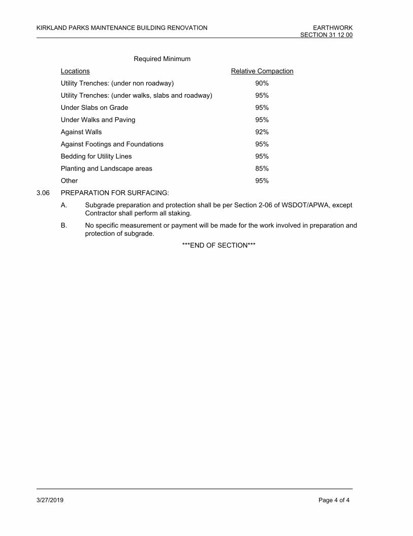
KIRKLAND PARKS MAINTENANCE BUILDING RENOVATION EARTHWORK SECTION 31 12 00
3/27/2019 Page 4 of 4
Required Minimum
Locations Relative Compaction
Utility Trenches: (under non roadway) 90%
Utility Trenches: (under walks, slabs and roadway) 95%
Under Slabs on Grade 95%
Under Walks and Paving 95%
Against Walls 92%
Against Footings and Foundations 95%
Bedding for Utility Lines 95%
Planting and Landscape areas 85%
Other 95%
3.06 PREPARATION FOR SURFACING:
A. Subgrade preparation and protection shall be per Section 2-06 of WSDOT/APWA, except Contractor shall perform all staking.
B. No specific measurement or payment will be made for the work involved in preparation and protection of subgrade.
***END OF SECTION***

KIRKLAND PARKS MAINTENANCE BUILDING RENOVATION TRENCH SAFETY SYSTEMS SECTION 31 41 33
3/27/2019 Page 1 of 1
PART 1 - GENERAL 1.1 SUMMARY
A. This section specifies requirements for the safety systems to be used in all excavation activities, including but not limited to storm, water, sewer, electrical trench, structure excavation and excavation for grading.
1.2 RELATED SECTIONS
A. Coordinate related work specified in other parts of the Project Manual, including but not limited to following:
Section 31 10 00 - Earthwork
1.3 REFERENCES
R.C.W. Chapter 49.17 WISHA.
WAC 296-155 Safety Standards for Construction Work.
WAC 296-155-660.
R.C.W. Chapter 39.04.180 Public Works/Trench Excavations - Safety Systems Required. PART 2 - PRODUCTS
Not Used
PART 3 - EXECUTION 3.1 EXCAVATION SAFETY SYSTEMS
A. Protect all excavation in excess of 4 feet in depth with a safety system conforming to the referenced requirements.
B. The Contractor’s excavation safety system shall be designed by a qualified person and meet the
referenced requirements. C. All excavation not requiring trench safety systems shall also meet the WISHA safety standards and the
requirements of Section 02300 - Earthwork.
***END OF SECTION***


KIRKLAND PARKS MAINTENANCE BUILDING RENOVATION ASPHALT CONCRETE PAVING SECTION 32 12 16
3/27/2019 Page 1 of 3
PART 1 - GENERAL 1.01 SUMMARY
A. Work includes but is not limited to the following:
1. New asphalt concrete paving, including crushed surfacing top course and asphalt treated base (ATB).
2. Permanent pavement patching. 3. Patching existing pavement to remain. 4. Sawcutting at edge of pavement to be removed and joined with new concrete paving.
B. Work shall be in accordance with the Standard Specifications for Road, Bridge and Municipal
Construction, most recent version, Washington State Department of Transportation/APWA
1.02 RELATED SECTIONS
A. Coordinate related requirements specified in other parts of the Project Manual, including but not limited to the following:
1. Section 02 41 16 – Building Demolition 2. Section 03 30 00 – Cast-in-Place Concrete
1.03 REFERENCES
APAW Designs and Specifications for Asphalt Concrete Pavements and Bases, most recent version.
WSDOT/APWA Standard Specifications for Road, Bridge and Municipal Construction, most
recent version, Washington State Department of Transportation/APWA 1.04 DESCRIPTION
A. This work shall consist of one or more courses of plant-mixed asphalt concrete placed on a prepared foundation or base in accordance with these Specifications and in close conformity with the lines, grades, thickness, and typical cross-sections shown in the plans.
1.05 SUBMITTALS
A. Submit Certificates: Furnish certification that all materials comply with Specification requirements; include laboratory test reports verifying compliance. Mixing plant to be member of Asphalt Paving Association of Washington (APAW) and approved by Engineer.
1.06 PROJECT SITE CONDITIONS
A. Environmental Requirements:
1. In accordance with referenced standard Specifications and the following: a. Do no paving in rain or when subgrade or base is wet or frozen. b. Do not apply tack coats when temperature is below 50 degrees F. or when
base is wet. c. Apply asphalt concrete paving only when temperature is above 40 degrees
and when base is dry.

KIRKLAND PARKS MAINTENANCE BUILDING RENOVATION ASPHALT CONCRETE PAVING SECTION 32 12 16
3/27/2019 Page 2 of 3
1.07 WARRANTY
A. Note that work correction is to include aggregate separation, soft spots, and excess porosity.
B. Repair cracks. Repair unsatisfactory elevation irregularities immediately upon notification; replace any paving not draining properly.
PART 2 - PRODUCTS 2.01 GENERAL
A. Comply with Quality Control Section provisions, Specifications, and Manufacturer's data. Where these may be in conflict, the more stringent requirements govern.
1. Match Existing Sections, or Conform to APAW - Section II, "Specifications for Asphalt
Paving" of above referenced manual. Provide bases, type and thickness of asphalt concrete as required by these Specifications and plans for site paving.
B. All materials shall conform to WSDOT Section 5-04.2.
2.02 CRUSHED SURFACING TOP COURSE
A. Where asphalt concrete paving is to be installed over previously unpaved areas, a top course of 5/8” maximum crushed surfacing aggregate shall be installed over the prepared subgrade as indicated and to depths shown on the plans. Gradation of the top course shall conform to WSDOT/APWA Section 9-03.9(3).
2.03 ASPHALT CONCRETE
A. Asphalt concrete shall be composed of asphalt and aggregate which, with or without the
addition of mineral filler and blending sand as may be required, shall be mixed in the proportions specified to provide a homogenous, stable and workable mixture.
B. Asphalt concrete shall be Class ½” conforming to WSDOT Section 5-04.
2.04 TACK COAT
A. Tack coat of asphalt shall have .05 to .08 gallons of retained asphalt per square yard of application and be in accordance with WSDOT 5-04.3(5)B.
PART 3 - EXECUTION 3.01 GENERAL
A. Verify installation conditions as satisfactory to receive work of this Section. Do not install until unsatisfactory conditions are corrected. Beginning work constitutes Contractor’s acceptance of conditions as satisfactory.
1. Construction shall conform to the details, dimensions and grades specified. Maximum
variations in finished grade of paving shall be +/- 1/8" in 10 feet.
B. Protect surrounding areas and surfaces to preclude damage from work of this Section.

KIRKLAND PARKS MAINTENANCE BUILDING RENOVATION ASPHALT CONCRETE PAVING SECTION 32 12 16
3/27/2019 Page 3 of 3
1. Protect work of other trades. Take special care in work adjacent to buildings. 2. Should any defacement or damage occur, repair or replace as directed.
C. Provide barricades and warning devices as required and in accordance with the current
Manual on Uniform Traffic Control Devices. 3.02 AGGREGATE TOP COURSE
A. Prepare subgrades and place crushed rock courses in conformance with WSDOT/APWA Section 4-04.
3.03 ASPHALT TREATED BASE
A. Preparation of asphalt, aggregates, mixing, hauling, spreading, finishing and compaction in accordance with WSDOT/APWA Section 4-06.
3.04 ASPHALT CONCRETE
A. Preparation of aggregates, mixing, hauling, spreading, finishing and compaction shall be as specified for Class ½” in WSDOT/APWA Section 5-04.3.
B. Joints and Connections with Existing Facilities shall be in accordance with WSDOT/APWA
Sections 5-04.3(11). C. Sampling and testing of asphalt concrete shall be in accordance with WSDOT/APWA Section
5-04.3(10)B. 3.05 TACK COAT
A. Tack coat shall be applied per WSDOT/APWA Section 5-04.3(5)B. 3.06 CLEANING
A. After completion of paving operations, clean surfaces of excess or spilled asphaltic materials. B. Do not permit vehicular traffic on asphaltic paving until it has cooled and hardened, and in no
case sooner than six (6) hours after placing. C. Provide barricades and warning devices to prevent traffic on asphalt paving and to alert
pedestrians to the surface condition.
***END OF SECTION***

KIRKLAND PARKS MAINTENANCE FACILITY DECORATIVE METAL FENCES AND GATES SECTION 32 31 19
3/27/2019 Page 1 of 3
PART I - GENERAL
1.01 SECTION INCLUDES:
A. Ornamental Rackable welded steel fence system.
B. Swinging vehicle gates
1.02 REFERENCES:
A. ASTM-F593-02e2_Stainless Steel Fasteners
B. ASTM A500 Seamless Grade A metal tubing
C. ASTM A123 Hot dip electroplating
D. ASTM E935 Cone Penetration test (Method D)
In-fill Load Test (Method C)
Vertical Concentrated Load Test (Method B)
Horizontal Load Test (Method A)
E. ASTM B117-97 Salt Spray Corrosion test
F. AC174 Section 4.2.2 In-Fill Load Test
Section 4.2.3 Uniform Load Test
Section 4.2.4 Concentrated Load Test
G. ICBO UBC-97 Quality standards
H. International Building Codes
1.03 WARRANTY
A. Provide a 5-year warranty for installation. Warranty to provide for replacement of panels damaged thru problems with installation, and re-installation of panels and posts.
PART II – PRODUCTS
2.01 MANUFACTURER
A. Design is based on: Fortress V2, as manufactured by:
Fortress Iron Railing and Fence Systems:
1800 Jay Ell, Suite 200
Richardson, Texas 75081
Phone: 866-323-4766 Fax: 972-644-3720
Web site: www.fortressfence.com
E-Mail: [email protected]
2.02 FENCE MATERIALS
A. Rails are Grade A cold rolled steel formed U-Channel conforming to ASTM A500 with G 60 zinc coating (0.60 oz/ft2) total inside and outside surfaces in accordance with the ASTM A123 hot dipped electroplating process. Materials

KIRKLAND PARKS MAINTENANCE FACILITY DECORATIVE METAL FENCES AND GATES SECTION 32 31 19
3/27/2019 Page 2 of 3
also conform to ASTM E935 testing (Methods A, B, C and D) and load testing in accordance with AC174 (Sections 4.2.2, 4.2.3 and 4.2.4).
B. Pickets are Grade A cold rolled steel formed and welded tubing conforming to ASTM A500 with G 60 zinc coating (0.60 oz/ft2) total inside and outside surfaces in accordance with the ASTM A123 hot dipped electroplating process. Materials also conform to ASTM E935 testing (Methods A, B, C and D) and load testing in accordance with AC174 (Sections 4.2.2, 4.2.3 and 4.2.4).
2.03 COMPONENTS
A. Rails: 14-gauge formed U-Channel ASTM 500 galvanized steel, 1-9/16-inch Leg X 1 3/16 inch Web.
B. Pickets: 14-gauge ASTM A500 galvanized welded and formed steel 3/4-inch square.
C. Posts: 16-gauge 2 1/2-inch square, 14-gauge 2 1/2inch square, 14-gauge 3-inch square. ASTM A500 galvanized formed and welded steel tubing with powder coated factory finish. Post caps can be pressed steel dome.
D. Fasteners: All nuts, bolts, sheet metal and wood screws are stainless steel conforming to ASTM F593-02e2 standard.
E. Fittings: Fabricated tees, elbows, splice connections; wall returns, wall ends and other similar components are of the same material, specification and finish as fence panels.
2.03 SWINGING GATE MATERIALS
A. Gates are to be bidder designed and fabricated, subject to the following criteria.
B. Fabricate to profiles and elevations shown on drawings.
C. Provide posts adequate to resist all normal forces
D Frames to constructed of square tube steel
E. Provide diagonal tube steel bracing
F. Provide barrel type bearing hinges.
G. Provide device to lock gates shut with key lock
H. Provide drop bolt or other device to hold gates open
I. Powder coat frames and posts
J. Gates to have no more than 4” clearance above grade when closed and locked.
K. Gates to have the same fabric as the fence.
L. Gates to be shop fabricated.
PART III – EXECUTION
3.01 PREPARATION
A. Stake layout showing locations of all gates and posts. Contact “CALL BEFORE YOU DIG” prior to beginning any excavation work.

KIRKLAND PARKS MAINTENANCE FACILITY DECORATIVE METAL FENCES AND GATES SECTION 32 31 19
3/27/2019 Page 3 of 3
3.02 INSTALLATION
A. Install fences in accordance with written instructions and in accordance with authorities having jurisdiction.
B. Concrete Set Posts: Drill hole in firm soil. Posts holes will be a minimum of 24 inches deep with a minimal diameter of 8 inches. Fence post (2 ½”) shall be spaced 95” on-center to accommodate installation of brackets on 2 ½” post.
C. Installation is to conform to the specifications referenced in Section 1.02 of this specification.
D. Install Fortress brackets onto fence section and posts as indicated in printed instructions for specific fence style. Attach fence sections to brackets with approved fasteners and techniques to insure that fence sections are parallel to grade within ¼-inch in 12 feet.
E. Install gates and verify ease of operation.
3.04 REPAIR
A. Paint damaged surfaces per 09 91 00.
3.05 CLEANING
A. Remove all cutting and drilling chips that are attached to the fencing, post, brackets or additions to prevent corrosion.
B. Repair scratches and other installation-incurred damage. Using a spray paint of the appropriate color that includes a zinc additive, repaint and seal any scratches or holes drilled in the fencing, post, brackets, or additions to prevent rust from forming.
C. Clean up debris and unused material and remove from site.
*** END OF SECTION 32 31 19***


KIRKLAND PARKS MAINTENANCE BUILDING RENOVATION SANITARY SEWER SECTION 33 30 00
3/27/2019 Page 1 of 3
PART 1 - GENERAL 1.1 SUMMARY
A. Work includes but is not limited to the following: 1. Furnishing and installing sanitary sewer pipe, fittings, and cleanouts of the type and sizes
designated in the plans and Specifications. 2. Locating the existing system and connecting the sysem to the building.
B. Work shall be in accordance with the Standard Specifications for Road, Bridge and Municipal Construction, most recent version, Washington State Department of Transportation/APWA
1.2 RELATED SECTIONS
A. Coordinate related work specified in other parts of the Project Manual.
1.3 REFERENCES
WSDOT/APWA Standard Specifications for Road, Bridge and Municipal Construction, 2006, Washington State Department of Transportation/APWA
1.4 DIMENSIONS AND LAYOUTS
A. The Contractor will be responsible for furnishing, setting, and marking all line location stakes. A qualified layout engineer, surveyor, or technical specialist must be assigned to the Contractor's crew for this work and shall be on site at all times when work requiring control is being performed, together with all necessary equipment, supplies, and instruments related thereto. This equipment and personnel must be available, at no additional cost to the Owner, for the purpose of verifying layout and certifying the accuracy of work on the site.
B. The Contractor is responsible for review of all records relative to the existing underground utilities. The
Contractor is responsible for avoiding damage to these facilities and shall restore all active utilities at the Contractor's own expense.
C. The Contractor is to notify the Owner immediately of underground utilities encountered which are not
shown on the drawings or Owner's survey or record drawings. PART 2 - PRODUCTS 2.1 POLYVINYL CHLORIDE PIPE (PVC) AND FITTINGS
A. PVC pipe shall conform to ASTM D3034 and shall be defined as flexible pipe. Joints shall conform to ASTM D3212 using a restrained rubber gasket conforming to ASTM F477.
B. Fittings shall be injection molded tees or factory solvent welded saddle tees. Saddles fastened to pipe
with external bands are not acceptable on any new system. 2.3 DUCTILE IRON PIPE AND FITTINGS
A. Ductile iron pipe shall conform to AWWA C151 Class 52 with push-on joints or mechanical joints, unless noted otherwise on plans. Ductile iron pipe shall be cement mortar lined conforming to AWWA C104.
KIRKLAND PARKS MAINTENANCE BUILDING RENOVATION SANITARY SEWER SECTION 33 30 00
3/27/2019 Page 2 of 3
B. Joints for ductile iron shall be rubber gasketed conforming to requirements of AWWA C-111/ANSI
A21-11. C. Fittings shall be ductile or cast iron, meet the same requirements as the connecting pipe, and conform
to COS Section 9-30.2(1). Saddles fastened to pipe with external bands shall not be acceptable on any new system.
2.4 HIGH DENSITY POLYETHYLENE (HDPE) PIPE AND FITTINGS
A. High Density Polyethylene (HDPE) pipe and fittings for forcemain (pressure) sewer systems shall be
in accordance with ASTM D3350. Pipe thickness shall be SDR 17, rated for minimum 100 psi. Pipe and fittings shall be designed for use with corrosive materials. HDPE pipe shall be Driscopipe 4200 Series or approved equivalent.
2.5 CONDUCTIVE WARNING TAPE
A. Conductive warning tape is required over all sewer, drainage, water and irrigation pipe. Tape shall be manufacturer's standard, permanent, bright-colored, continuous printed plastic tape, aluminum backed, intended for direct-burial service. Tape shall be not less than 6" wide x 4 mils thick. Tape Schedule:
Piping Color Wording Sanitary Sewer Green Caution Sanitary Sewer
2.6 FITTINGS, COUPLINGS AND JOINTS
A. Fittings shall be the same material as the pipe. B. Tees on existing pipe and new connections to manholes shall be connected by core drilling and
flexible connections. Connections to existing pipes shall be made with Inserta-Tee fittings. C. Pipe-to-pipe connections between pipes of differing material shall be made with a flexible gasketed
coupling, adaptor or coupling-adaptor to make a watertight joint. Couplings shall be those manufactured by Romac, Caulder, or Fernco, as approved by the Engineer.
D. Joint types utilized on concrete pipe shall be consistent within individual manhole runs.
2.7 BEDDING AND BACKFILL MATERIAL
A. Bedding material shall be in accordance with Section 31 12 00, Earthwork. B. Backfill material shall be in accordance with Section 31 12 00, Earthwork.
2.8 CLEANOUTS
A. Cleanouts shall be installed in accordance with the Plans and Details. PART 3 - EXECUTION 3.1 COORDINATION WITH OTHER WORK

KIRKLAND PARKS MAINTENANCE BUILDING RENOVATION SANITARY SEWER SECTION 33 30 00
3/27/2019 Page 3 of 3
A. Verify location from the records. B. Before installation, Contractor shall make proper provisions for site sanitary sewer lines and to avoid
interference with installation of other work and/or other contractors. Any changes caused by Contractor's neglect to coordinate work shall be made by Contractor at Contractor's expense.
3.2 TRENCHING AND PIPE LAYING
A. Excavation and preparation of the trench shall be in accordance with Section 31 12 000, Earthwork. All trenching shall conform to City of Kirkland Standards, the Washington Administrative Code (WAC) 296-155 and WISHA requirements for Excavation, Trenching and Shoring. (See Section 02165, Trench Safety Systems.)
B. Excavation shall be made to alignment, elevation, grade and slope as indicated on the drawings. C. Laying shall be in conformance with Section 02300 and WSDOT/APWA Section 7-08.3(2).
3.4 BEDDING AND BACKFILLING
A. Bedding and backfill shall be per Section 31 12 00 and the details in the Plans.
3.6 CLEANING AND TESTING A. Cleaning and testing shall be in conformance with Section 7-17.3(2) of WSDOT/APWA.
3.7 PERMANENT CONNECTIONS TO EXISTING SYSTEMS
A. Where indicated on the plans, make permanent connections to existing sewer systems. B. Where existing pipe is to be connected to a new structure, replace existing pipe and/or add fittings
and pipe as necessary to provide an approved connection per the plans. C. Where new pipe is to be connected to an existing structure, rebuild structure as necessary to provide
an approved connection per the plans. Rechannel the structure and modify ladder rungs as necessary.
***END OF SECTION***