Project: IEEE P802.15 Working Group for Wireless Personal Area Networks (WPANs)
Upload
rogan-reidCategory
view
9download
0description
November 2003
CRL-UWB ConsortiumSlide1Submission
doc.:IEEE802.15-03-0472-00-003a
Project: IEEE P802.15 Working Group for Wireless Personal Area Networks (WPANS)Project: IEEE P802.15 Working Group for Wireless Personal Area Networks (WPANS)
Submission Title: [CRL-UWB Consortium - Ultra Wideband Printed Bow-Tie Antenna]Date Submitted: [November 2003]Source: [Kamya Yekeh Yazdandoost, Ryuji Kohno] Company [(1) Communications Research Laboratory (CRL), (2) CRL-UWB Consortium] Connector’s Address [3-4, Hikarino-oka, Yokusuka, 239-0847, Japan] Voice: [+81-56-847-5435], FAX: [+81-46-847-5431] E-mail: [[email protected], [email protected]] Re: [IEEE P802.15 Alternative PHY Call for Proposals, IEEE P802.15-02/327r7]Abstract: [This presentation is Introduction to the Printed Bow-Tie Antenna for UWB system.]Purpose: [Antenna for 802.15.TG3a]Notice: [This document has been prepared to assist the IEEE P802.15. It is offered as a basis for discussion and is not binding on the contributing individual(s) or organization(s). The material in this document is subject to change in form and content after further study. The contributor(s) reserve(s) the right to add, amend or withdraw material contained herein.]Release: [The contributor acknowledges and accepts that this contribution becomes the property of IEEE and may be made publicly available by P802.15.]

November 2003
CRL-UWB ConsortiumSlide2Submission
doc.:IEEE802.15-03-0472-00-003a
ULTRA WIDEBAND PRINTED BOW-TIE ANTENNA
Kamya Yekeh Yazdandoost
Ryuji Kohno
Director, UWB Technology Institute, CRL
Professor, Yokohama National University
Chair, CRL-UWB Consortium
Presented by Yuko Rikuta
Communications Research Laboratory (CRL)
& CRL-UWB Consortium

November 2003
CRL-UWB ConsortiumSlide3Submission
doc.:IEEE802.15-03-0472-00-003a
Presentation Overview
• Introduction• Patch Antenna • Printed Bow-Tie Antenna• UWB Antenna Design Challenge• UWB Printed Bow-Tie Antenna • Wideband Mechanism of Printed Bow-Tie Antenna• Results• Conclusions

November 2003
CRL-UWB ConsortiumSlide4Submission
doc.:IEEE802.15-03-0472-00-003a
Introduction• Antenna performance and size have a large impact
on the development of wireless system.• It is more complicated to provide the typical
parameters like Bandwidth, Efficiency, and Gain within the limited antenna volume.
• This is more critical with respect to the UWB Antenna.
• It is well-known that the UWB antenna design remains to be the major face in the progress of UWB technology.

November 2003
CRL-UWB ConsortiumSlide5Submission
doc.:IEEE802.15-03-0472-00-003a
Patch Antenna Patch antennas are extensively used in different wireless applications due to:
– Low profile – Light weight– Easy to fabricate– Low cost
The major drawback is narrow bandwidth
Because of it limited bandwidth, several designs of broadband patch antenna have been reported
But the question is, a broadband antenna can be UWB antenna ?

November 2003
CRL-UWB ConsortiumSlide6Submission
doc.:IEEE802.15-03-0472-00-003a
Traditional Printed Bow-Tie Antenna
Patch
Ground Plane Side view
Top view
Feed Point
Substrate

November 2003
CRL-UWB ConsortiumSlide7Submission
doc.:IEEE802.15-03-0472-00-003a
UWB Antenna Design Challenge
• Compact size while providing acceptable: 1- VSWR 2- Bandwidth 3- Gain 4- Efficiency• Omni-directional pattern• To be suitable for on chip design, with good impedance
matching• Light weight• Low cost
November 2003
CRL-UWB ConsortiumSlide8Submission
doc.:IEEE802.15-03-0472-00-003a
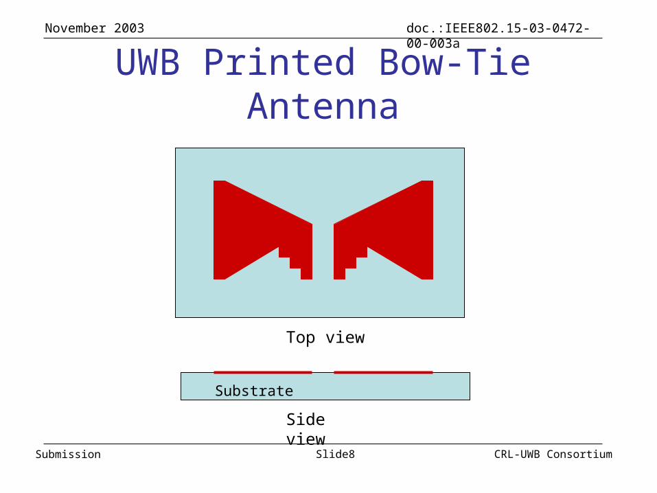
UWB Printed Bow-Tie Antenna
Substrate
Top view
Side view
November 2003
CRL-UWB ConsortiumSlide9Submission
doc.:IEEE802.15-03-0472-00-003a
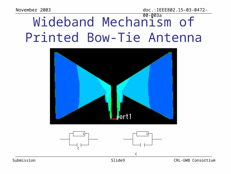
Wideband Mechanism of Printed Bow-Tie Antenna
L
C
L
C

November 2003
CRL-UWB ConsortiumSlide10Submission
doc.:IEEE802.15-03-0472-00-003a
Results Field Distributions

November 2003
CRL-UWB ConsortiumSlide11Submission
doc.:IEEE802.15-03-0472-00-003a
Results
VSWR< 3 (3.8 to 10.6GHz)
Frequency GHz
Mag
nitu
de o
f V
SW
RVSWR

November 2003
CRL-UWB ConsortiumSlide12Submission
doc.:IEEE802.15-03-0472-00-003a
ResultsS11
S11< -6 dB (3.8 to 10.6GHz)
Mag
nitu
de o
f S
catt
erin
g M
atri
x (d
B)
Frequency GHz

November 2003
CRL-UWB ConsortiumSlide13Submission
doc.:IEEE802.15-03-0472-00-003a
Results
Frequency (GHz)
Mag
nitu
de o
f G
ain
(dB
i)GAIN
Gain > 2 dBi (3 to 10.6GHz)
November 2003
CRL-UWB ConsortiumSlide14Submission
doc.:IEEE802.15-03-0472-00-003a
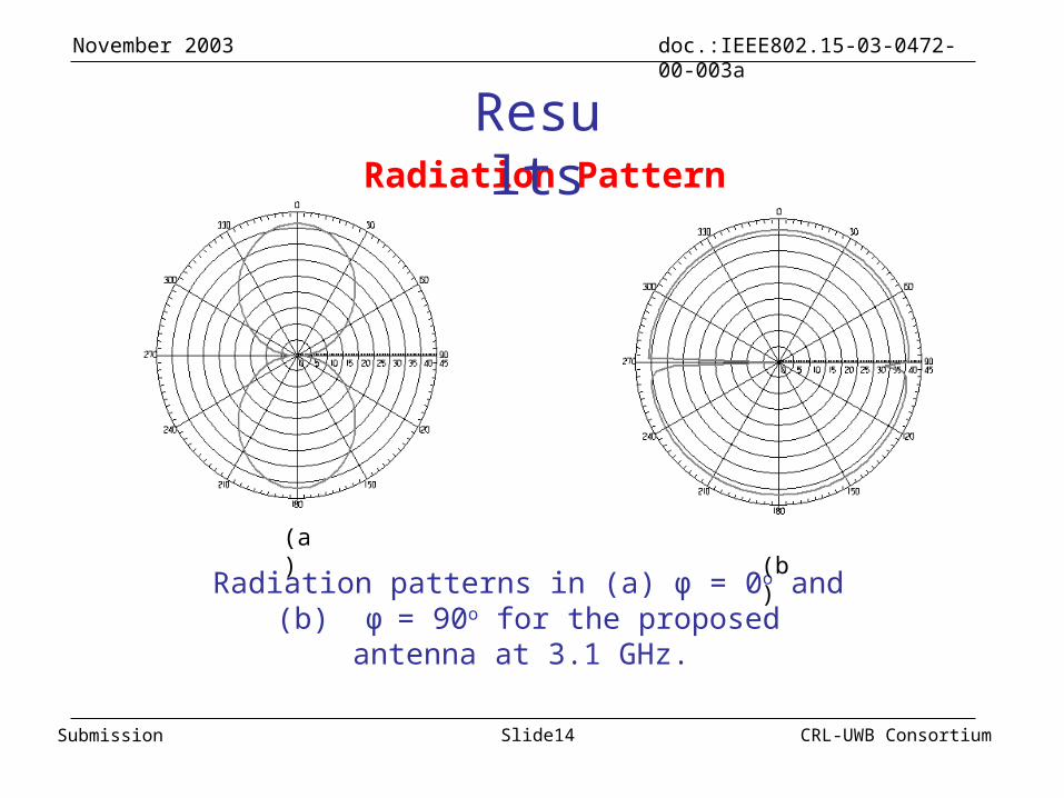
Radiation Pattern
Results
Radiation patterns in (a) φ = 0o and (b) φ = 90o for the proposed antenna at 3.1 GHz.
(a) (b)

November 2003
CRL-UWB ConsortiumSlide15Submission
doc.:IEEE802.15-03-0472-00-003a
Radiation Pattern (Cont.)
Results
Radiation patterns in (a) φ = 0o and (b) φ = 90o for the proposed antenna at 5.1 GHz.
(a) (b)

November 2003
CRL-UWB ConsortiumSlide16Submission
doc.:IEEE802.15-03-0472-00-003a
Radiation Pattern (Cont.)
Results
Radiation patterns in (a) φ = 0o and (b) φ = 90o for the proposed antenna at 7.1 GHz.
(a) (b)
November 2003
CRL-UWB ConsortiumSlide17Submission
doc.:IEEE802.15-03-0472-00-003a
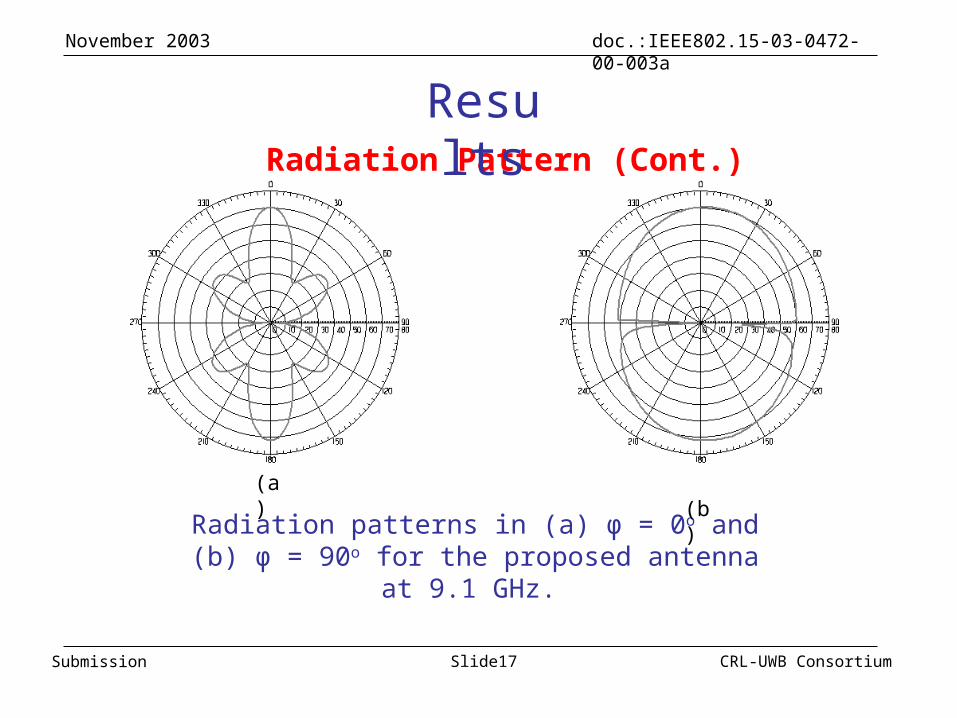
Radiation Pattern (Cont.)
Results
Radiation patterns in (a) φ = 0o and (b) φ = 90o for the proposed antenna at 9.1 GHz.
(a) (b)

November 2003
CRL-UWB ConsortiumSlide18Submission
doc.:IEEE802.15-03-0472-00-003a
Results3D Radiation Pattern
Antenna
Z
x
y

November 2003
CRL-UWB ConsortiumSlide19Submission
doc.:IEEE802.15-03-0472-00-003a
Antenna Prototype

November 2003
CRL-UWB ConsortiumSlide20Submission
doc.:IEEE802.15-03-0472-00-003a
Conclusions
The 3D radiation pattern of antenna is showing that, it has . excellent performance for wireless devices, especially for . . UWB system
Satisfied the required bandwidth for UWB systems
A thin and small antennas on FR-4 substrate
Greater than 2 dBi gain was shown to be achievable over the frequency range
Easy to design for on chip device