Project Home Cockpit By Rays Aviation · PDF fileProject Home Cockpit By Rays Aviation Intro...
21
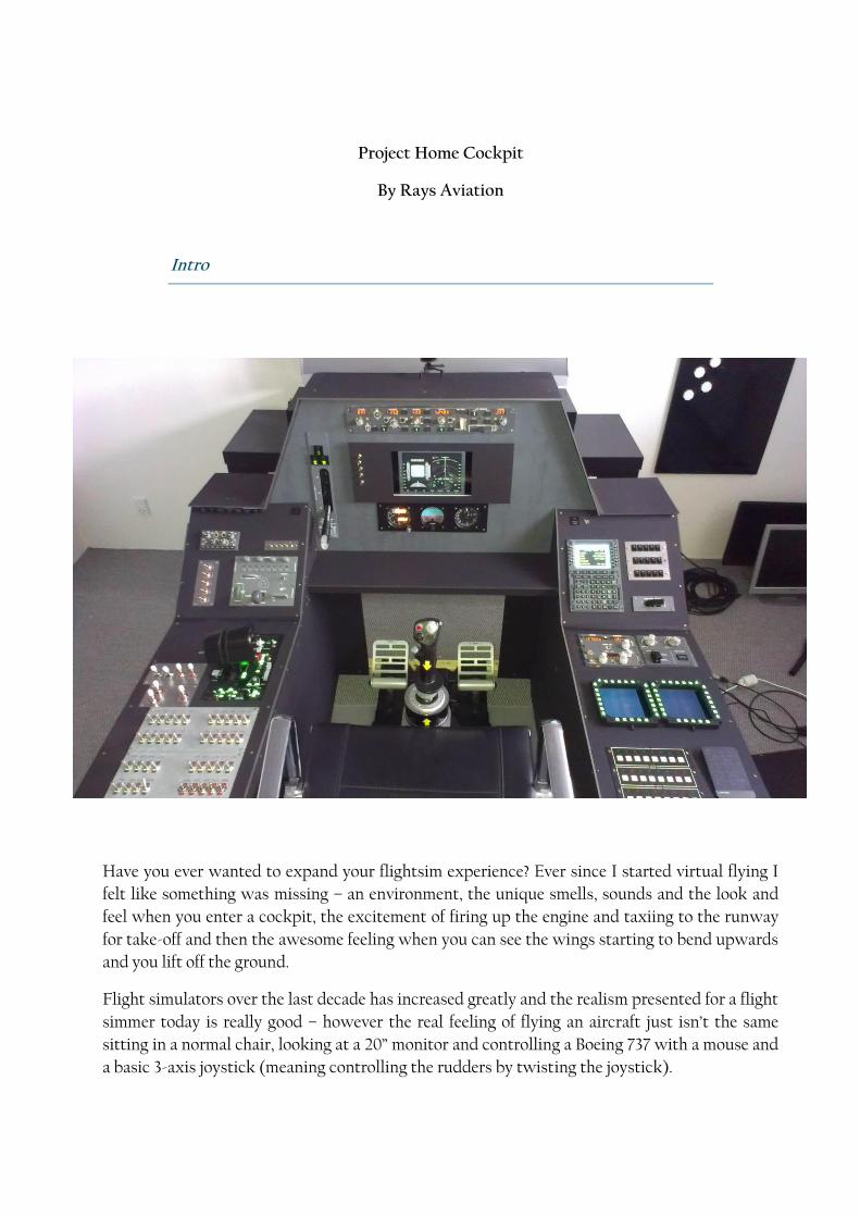
Project Home Cockpit By Rays Aviation Intro Have you ever wanted to expand your flightsim experience? Ever since I started virtual flying I felt like something was missing – an environment, the unique smells, sounds and the look and feel when you enter a cockpit, the excitement of firing up the engine and taxiing to the runway for take-off and then the awesome feeling when you can see the wings starting to bend upwards and you lift off the ground. Flight simulators over the last decade has increased greatly and the realism presented for a flight simmer today is really good – however the real feeling of flying an aircraft just isn’t the same sitting in a normal chair, looking at a 20” monitor and controlling a Boeing 737 with a mouse and a basic 3-axis joystick (meaning controlling the rudders by twisting the joystick).
Transcript of Project Home Cockpit By Rays Aviation · PDF fileProject Home Cockpit By Rays Aviation Intro...
Project Home Cockpit
By Rays Aviation
Intro
Have you ever wanted to expand your flightsim experience? Ever since I started virtual flying I
felt like something was missing – an environment, the unique smells, sounds and the look and
feel when you enter a cockpit, the excitement of firing up the engine and taxiing to the runway
for take-off and then the awesome feeling when you can see the wings starting to bend upwards
and you lift off the ground.
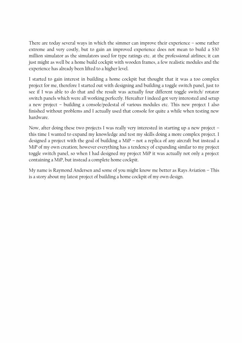
Flight simulators over the last decade has increased greatly and the realism presented for a flight
simmer today is really good – however the real feeling of flying an aircraft just isn’t the same
sitting in a normal chair, looking at a 20” monitor and controlling a Boeing 737 with a mouse and
a basic 3-axis joystick (meaning controlling the rudders by twisting the joystick).
There are today several ways in which the simmer can improve their experience – some rather
extreme and very costly, but to gain an improved experience does not mean to build a $30
million simulator as the simulators used for type ratings etc. at the professional airlines; it can
just might as well be a home build cockpit with wooden frames, a few realistic modules and the
experience has already been lifted to a higher level.
I started to gain interest in building a home cockpit but thought that it was a too complex
project for me, therefore I started out with designing and building a toggle switch panel, just to
see if I was able to do that and the result was actually four different toggle switch/ rotator
switch panels which were all working perfectly. Hereafter I indeed got very interested and setup
a new project – building a console/pedestal of various modules etc. This new project I also
finished without problems and I actually used that console for quite a while when testing new
hardware.
Now, after doing these two projects I was really very interested in starting up a new project –
this time I wanted to expand my knowledge and test my skills doing a more complex project. I
designed a project with the goal of building a MiP – not a replica of any aircraft but instead a
MiP of my own creation; however everything has a tendency of expanding similar to my project
toggle switch panel, so when I had designed my project MiP it was actually not only a project
containing a MiP, but instead a complete home cockpit.
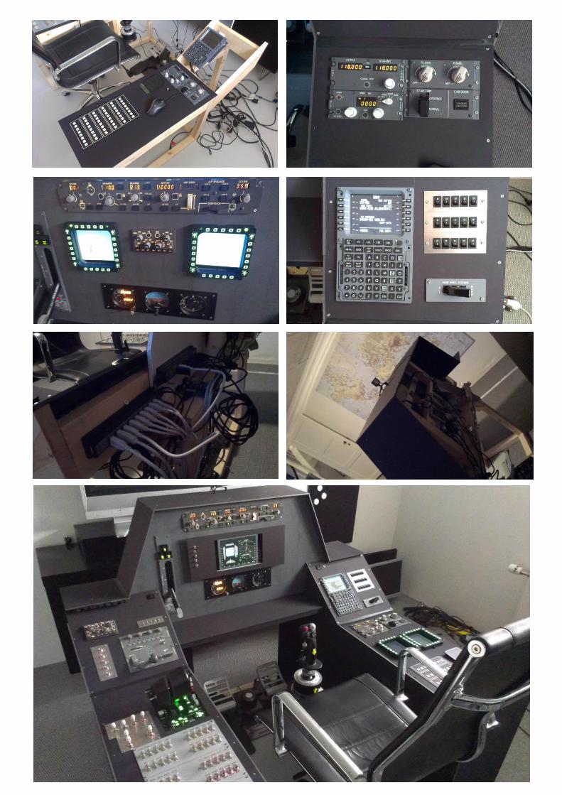
My name is Raymond Andersen and some of you might know me better as Rays Aviation – This
is a story about my latest project of building a home cockpit of my own design.
Scoping & Designing
The first thing I did when I decided to start this project was trying to define what I actually
wanted to do and what the goal should be. If I needed progress goals to keep me going and
which additional challenges I wanted to give myself during the project.
What I wanted to do was to build a home cockpit which was not a replica of any kind, which
included most of the hardware units that I had previously tested and reviewed, which could be
connected to just one single computer, which was not a turn-key solution, which included
modules or products from at least 10 different suppliers and which would feature both a glass
cockpit function but also the old standard gauges. The home cockpit should of course be
compatible with MS FSX since that is the flight simulator platform that I am using, and the
controls should be HOTAS throttle and stick which I prefer.
Cockpit of own creation => not a replica but okay to use replica modules etc.
Use most of the hardware that I already had in my portfolio
Setup should only be featuring one computer (would cause issues in regards to the video
outputs but I had a plan…)
The MiP should be both a glass cockpit but also include old fashioned gauges
Compatible with Microsoft FSX
Controls had to be HOTAS throttle and stick configuration
Use products from at least 10 different suppliers
Must NOT be a turn-key solution
I decided that I wanted to build the cockpit as a single seated cockpit since I would be using the
HOTAS configuration – of course the HOTAS configuration could also apply in a twin seated
cockpit but normally this configuration is seen and used in single seated configurations.
When creating a single seated cockpit I now did not have to build a pedestal which is normally
found between the pilots in a twin seated cockpit. Instead I had to build both a left side and
right side console supporting a variety of modules and functions together with the MiP. I
decided that I did not want to build an overhead for this home cockpit (could be an additional
project in the future), so the overall to build was only:
Left side console
Right side console
MiP
Support for rudder
Support for stick mounted on seat
I started by placing all my current hardware on the floor and there from marking each unit with
either MiP, Left console, Right console, seat, floor etc. so that I could gain an overview of which
units I wanted to place where.
I hereafter marked an area on the floor covering both the left and right console and started
placing the units where I thought it would be the most logical to place them. I did the same with
the units for the MiP and quickly ended up with 10 or 15 different layouts. Now I just had to
choose which layout would fit my idea the best.
Now I selected which layout I wanted to go with and laid out all modules on the floor for both
consoles and the MiP, took a picture and slept on the idea for a few days. I looked at the picture
a huge number of times to try and see how it could be better – it was as something was missing
and I wanted to make it more complex and include more switches etc.
This ended up in me actually designing additional modules for the cockpit – well front plates
that could support some different switches. I started searching for switches that would fit my
design and idea. I wanted to give my cockpit a touch of a Boeing B737 besides the replica
modules that I had, so I went to Opencockpits webshop and ordered some Boeing B737 toggle
switches which has the characteristic white cap.
I also searched DX.com (Deal Extreme) for additional small toggle switches and click switches –
I found some various switches and ordered them. Now that all was ordered I also had the correct
the measurements for the holes etc. that needed to be cut in the front plates.
I updated my drawings and mailed them to one of my contacts “Hedensted Maskinfabrik” who
has several machines that are able to laser cut metal – He quickly put my drawings into his
production line and the output was some excellent cut aluminum front plates of my own
creation.
Previously I had built some toggle switch panels so this time it was quite simple and I knew
how to proceed. I now had the front panels and the switches that should be a part of the
additional self-designed modules, so all I now needed was to connect them to some PCBs – I had
some PCBs from Desktop Aviator from my previous project that had some free connection pins,
and additionally I also had several PCBs from Opencockpits that also could be used for
connecting these new modules – the output was a combination of both and I now had a great
variety of modules for the complete setup.

Additionally I also had to figure out how and what kind of materials I wanted to use when
building the cockpit. Should the frames be built of plastic, metal or wood and if metal then what
kind of metal… I had the same issue if I was to choose wood as the material – what size, form and
quality should it then be.
I have no experience working with metal as steel or aluminum which I thought would be the
ideal material for this project – this was however also very expensive and I would need a lot of
outside help just to get the project started, so my solution ended up being wood for the frames
in the cockpit.Since I am actually an office working guy my skills working with wood, screws
etc. is quite limited, but I had ideas and dedication and I was not afraid to try.
One thing was the frames but what about the MiP – I had previously used plywood as a top for a
console, but to be honest I found that solution to be a bad idea because the plywood has a very
rough surface. That combined with the fact that I did not want to use aluminum or steel gave me
a challenge and I had to find a completely different material to use.
I found a Danish website created by a person who had built a Boeing B737 captains side cockpit
and he had used a material called FoamAlux, which is foamed PVC (polyvinylchloride) that has
the strength like plywood, or actually probably even better, and the surface is super smooth. To
process this material was described to be very easy – only using a Stanley knife or similar, but
that I later found out would be a modification of reality, or maybe that was because the person
who had used this material, had used a thinner piece than what I would later on use.
I selected the FoamAlux as material for the MiP and ordered at the local DIY shop one plate
with a thickness of 10mm – this was way to think for me to process simply by using the Stanley
knife, so I had to use a small manual saw and also an electrical saw to ease the processing, no
problem though - it's like the phrase "Learning by Doing".
Now my only concern in regards to materials was the glare wings and top + sides of the consoles
– my first ideas was to use the FoamAlux for that also, but that would be an incredible
expensive solution so I had to find a different solution. I went to the local DIY shop and looked
around. I found various possible solutions as 3-5mm FoamAlux, plywood, hardened plastics as
Plexiglas and acrylic plates, various hardened foam products and the Kapa Graph plate which is
foamed carton in 5mm.
The Kapa Graph material was already colored black, easy to process, price wise very fair and it
had enough stability for what I needed – the few places where I needed additional stability I
could support the Kapa Graph with wood on the back side + all screws mounted into the Kapa
Graph would also be fastened into the wood behind because the density of the Kapa Graph is
not sufficient enough to withhold screws properly.
The build
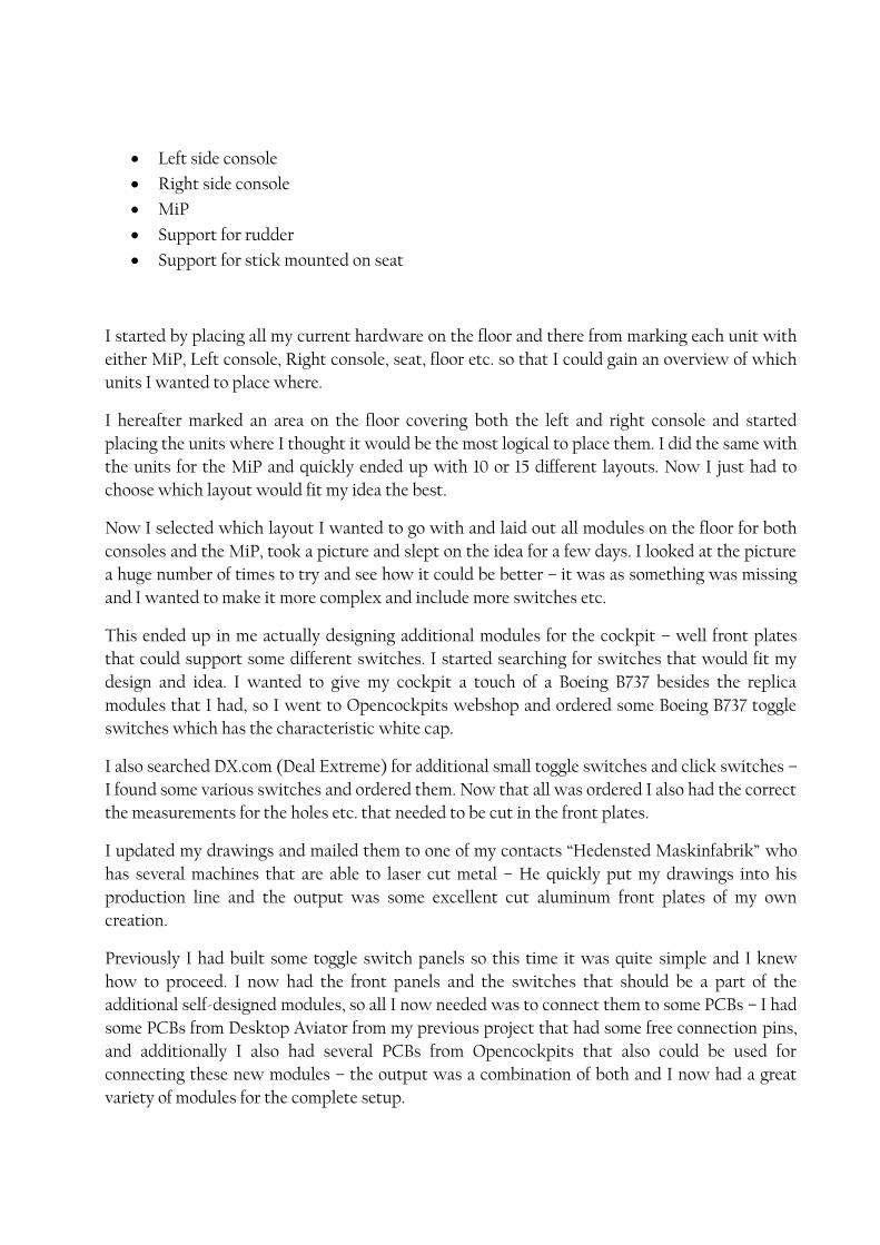
I started out by building the frames for the left and right console, and I remembered to make
sure that the left console had a support for the dual throttle that I was going to place there. That
was a very essential part and something that I easily could have overlooked until I were to place
the throttle to the setup... yea
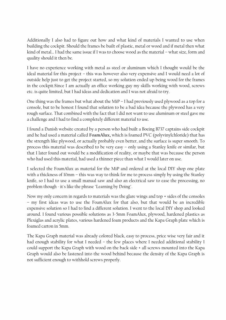
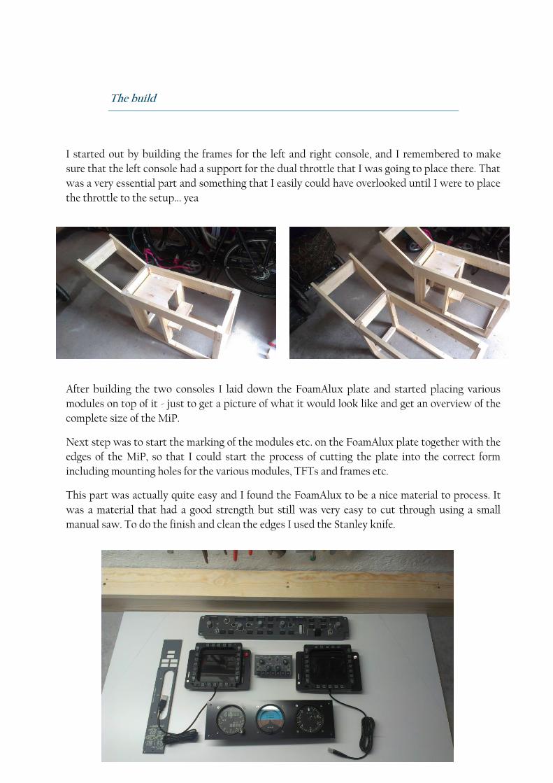
After building the two consoles I laid down the FoamAlux plate and started placing various
modules on top of it - just to get a picture of what it would look like and get an overview of the
complete size of the MiP.
Next step was to start the marking of the modules etc. on the FoamAlux plate together with the
edges of the MiP, so that I could start the process of cutting the plate into the correct form
including mounting holes for the various modules, TFTs and frames etc.
This part was actually quite easy and I found the FoamAlux to be a nice material to process. It
was a material that had a good strength but still was very easy to cut through using a small
manual saw. To do the finish and clean the edges I used the Stanley knife.
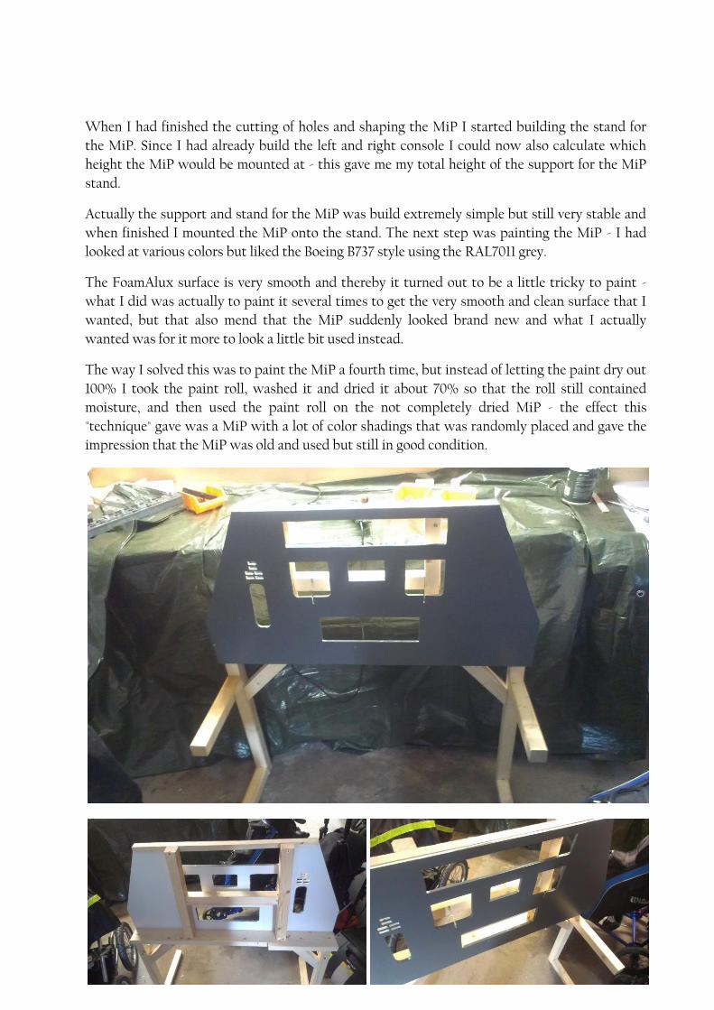
When I had finished the cutting of holes and shaping the MiP I started building the stand for
the MiP. Since I had already build the left and right console I could now also calculate which
height the MiP would be mounted at - this gave me my total height of the support for the MiP
stand.
Actually the support and stand for the MiP was build extremely simple but still very stable and
when finished I mounted the MiP onto the stand. The next step was painting the MiP - I had
looked at various colors but liked the Boeing B737 style using the RAL7011 grey.
The FoamAlux surface is very smooth and thereby it turned out to be a little tricky to paint -
what I did was actually to paint it several times to get the very smooth and clean surface that I
wanted, but that also mend that the MiP suddenly looked brand new and what I actually
wanted was for it more to look a little bit used instead.
The way I solved this was to paint the MiP a fourth time, but instead of letting the paint dry out
100% I took the paint roll, washed it and dried it about 70% so that the roll still contained
moisture, and then used the paint roll on the not completely dried MiP - the effect this
"technique" gave was a MiP with a lot of color shadings that was randomly placed and gave the
impression that the MiP was old and used but still in good condition.
I had now finished the 3 main components of the home cockpit and I started the process of
assembling the left and right console with the MiP. This was really an easy job because I had
chosen to use wood instead of metal, so the assembly was done using ordinary torx screws and
it did not take that much time.
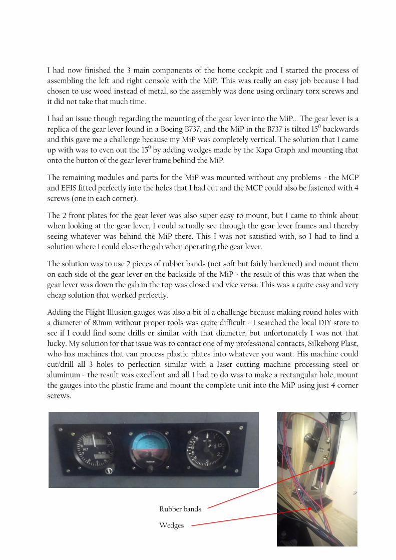
I had an issue though regarding the mounting of the gear lever into the MiP... The gear lever is a
replica of the gear lever found in a Boeing B737, and the MiP in the B737 is tilted 150 backwards
and this gave me a challenge because my MiP was completely vertical. The solution that I came
up with was to even out the 150 by adding wedges made by the Kapa Graph and mounting that
onto the button of the gear lever frame behind the MiP.
The remaining modules and parts for the MiP was mounted without any problems - the MCP
and EFIS fitted perfectly into the holes that I had cut and the MCP could also be fastened with 4
screws (one in each corner).
The 2 front plates for the gear lever was also super easy to mount, but I came to think about
when looking at the gear lever, I could actually see through the gear lever frames and thereby
seeing whatever was behind the MiP there. This I was not satisfied with, so I had to find a
solution where I could close the gab when operating the gear lever.
The solution was to use 2 pieces of rubber bands (not soft but fairly hardened) and mount them
on each side of the gear lever on the backside of the MiP - the result of this was that when the
gear lever was down the gab in the top was closed and vice versa. This was a quite easy and very
cheap solution that worked perfectly.
Adding the Flight Illusion gauges was also a bit of a challenge because making round holes with
a diameter of 80mm without proper tools was quite difficult - I searched the local DIY store to
see if I could find some drills or similar with that diameter, but unfortunately I was not that
lucky. My solution for that issue was to contact one of my professional contacts, Silkeborg Plast,
who has machines that can process plastic plates into whatever you want. His machine could
cut/drill all 3 holes to perfection similar with a laser cutting machine processing steel or
aluminum - the result was excellent and all I had to do was to make a rectangular hole, mount
the gauges into the plastic frame and mount the complete unit into the MiP using just 4 corner
screws.
Rubber bands
Wedges
The last pieces of the MiP was the TFTs which should be mounted on the backside of the MiP
and the 2 MFD frames that should be mounted on the front side but the wires should connect
behind the MiP. This was no problem - the MFDs could be mounted just by using a little bit of
glue and for the cables I had drilled 2 small openings at the button and center of each window.
Next was mounting the TFTs and this turned out to be extremely easy as well - I could use the
support that I had made for the MiP to also support the TFTs - all that was needed additionally
was 2 screws for each TFT which was screwed into the backside of the MiP just below the TFTs
=> meaning that the TFTs would be resting on the screws and at the same time being supported
by the MiP support (the H-frame).
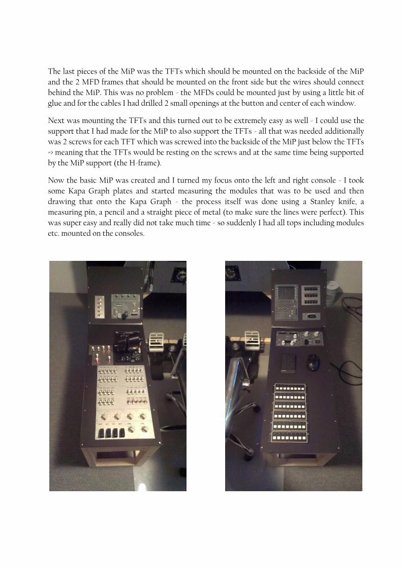
Now the basic MiP was created and I turned my focus onto the left and right console - I took
some Kapa Graph plates and started measuring the modules that was to be used and then
drawing that onto the Kapa Graph - the process itself was done using a Stanley knife, a
measuring pin, a pencil and a straight piece of metal (to make sure the lines were perfect). This
was super easy and really did not take much time - so suddenly I had all tops including modules
etc. mounted on the consoles.

After the tops were created and mounted I only remained to mount some Kapa Graph on the
sides etc. to close the consoles and create the cockpit look - this however I could not yet do
because I had only mounted the various modules etc. but they were not yet connected.
Before I put my focus on the connection of everything I wanted to mount the rudder pedals - I
wanted them to be one with the setup and not just some "loose" placed pedals which I
previously have had some issues with. Before I created this cockpit the rudder pedals was just
placed on the floor, but when using them then quite often the pedals moved out of place when
applying rudder => really annoying!
Therefore I mounted a wooden bar between the left and right leg-support for the MiP and on
this bar I mounted the rudder pedals using screws. Now the rudder was indeed an integrated
part of the setup, and if they were to move, it would mean that the complete setup would move
(not likely to happen).
Last challenge in the build was the control stick - the quick and dirty way of adding that to the
setup would have been to mount it on the right side console... but I had a different idea. Modern
military aircrafts like e.g. the F-35 has the stick mounted on the right side of the cockpit as also
the F-16, but I more like the idea with placing the stick between the legs as the F-18 or similar.
This would however mean that I needed to create a floor support or some kind of integration
with my chair. The floor support idea I discharged quickly and started thinking about ways to
integrate the stick to my chair.
The solution I came up with was a special cut metal plate that could be squeezed in between the
brackets below the chair meaning no screws or anything was needed to mount the plate. In the
metal plate was drilled 4 holes according to the locations of the 4 mounting screws used for my
control stick and mounted it now was.


Connecting everything - Part 1
The build was great fun indeed but the next stage of the project would be even more fun, but
also at times extremely frustrating it turned out to be - the connection of all modules and getting
everything to work together.
To get an overview I gathered everything into groups like controls, displays, PCB connected
modules as well as what could be connected by VGA or HDMI or USB. Furthermore I also
created a subgroup for the USB connections where I gathered USBs that could go into a hub and
USBs that needed a direct connection.
I found that the wiring was actually quite extensive and getting everything connected and
working properly was a challenge in itself. The first step was to get the toggle switch panels
connected properly to the PCBs before I would be able to connect them to the USBs - this was a
nightmare - my own build panels featured a total of 6x 12-pos, 1-pole rotator switches, 15 on/off
click switches, 5 on/on toggle switches, 44 on/off toggle switches, 5 on/off/on toggle switches, 3
momentary on/off/on switches, a nose wheel steering module switch and the gear lever with 2
micro switches.... damn.... - color coding groups of wires I found to be a good idea!
Finally I got all these wires connected to the supporting PCBs and could now set my focus on
the connection of the USBs, VGA and HDMI, but...... there was actually one more thing that I
had to find a solution for. I had created a backlight function and had some various LEDs that
needed power - some LEDs was connected through the PCBs from Opencockpits, so these I did
not have to find a solution for, but the other LEDs that was a part of the setup together with the
cooling fan for the Tracker IR5, I needed to have a power source for. That together with a 220v
power source for the power converters used for some of the modules as the CPFlight backlight
function and the Opencoickpits FMC v3 (CDU) and the Flight Illusion gauges.
What I did was to build a 220v power station in the right console and from there I connected
some power converters to build a low voltage power station, also placed in the right console -
this low voltage power station contained output of both 5v and 12v - so now I had sufficient
power to support all modules including the USB hubs needed.
Before I connected the various cables I made a connection diagram so that I was sure that I had
sufficient USB cables to support all functions. This diagram was actually quite complex and
later in this article you will see the updated version (I had to make some changes due to some
issue that came up).
I had some modules as the CP Flight MCP, the Opencockpits FMC v3, the ThrustMaster
throttle and the Tracker IR5 which apparently needed a direct connection - furthermore I had
the 2 TFTs which were to be connected through USBs (2 USBs per TFT) and that took a whole
lot of USB connections and power - and since I was only using one computer I was quite limited
by the USB outputs available on the computer....
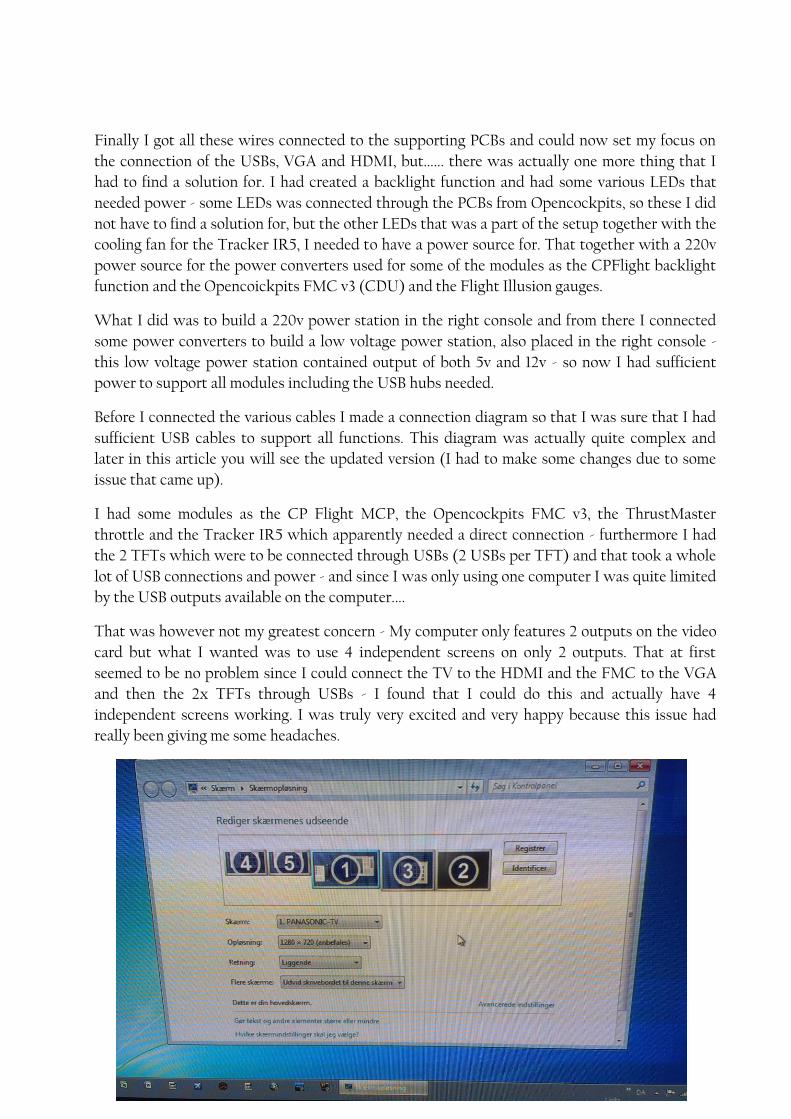
That was however not my greatest concern - My computer only features 2 outputs on the video
card but what I wanted was to use 4 independent screens on only 2 outputs. That at first
seemed to be no problem since I could connect the TV to the HDMI and the FMC to the VGA
and then the 2x TFTs through USBs - I found that I could do this and actually have 4
independent screens working. I was truly very excited and very happy because this issue had
really been giving me some headaches.
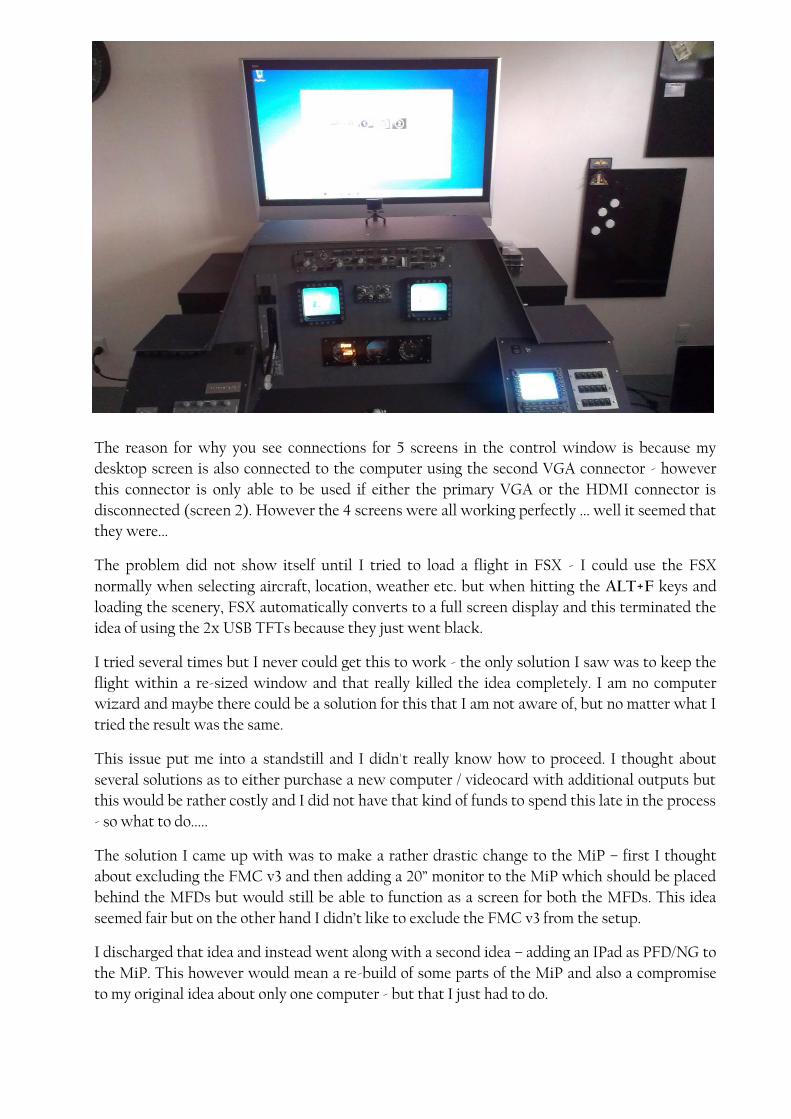
The reason for why you see connections for 5 screens in the control window is because my
desktop screen is also connected to the computer using the second VGA connector - however
this connector is only able to be used if either the primary VGA or the HDMI connector is
disconnected (screen 2). However the 4 screens were all working perfectly ... well it seemed that
they were...
The problem did not show itself until I tried to load a flight in FSX - I could use the FSX
normally when selecting aircraft, location, weather etc. but when hitting the ALT+F keys and
loading the scenery, FSX automatically converts to a full screen display and this terminated the
idea of using the 2x USB TFTs because they just went black.
I tried several times but I never could get this to work - the only solution I saw was to keep the
flight within a re-sized window and that really killed the idea completely. I am no computer
wizard and maybe there could be a solution for this that I am not aware of, but no matter what I
tried the result was the same.
This issue put me into a standstill and I didn't really know how to proceed. I thought about
several solutions as to either purchase a new computer / videocard with additional outputs but
this would be rather costly and I did not have that kind of funds to spend this late in the process
- so what to do.....
The solution I came up with was to make a rather drastic change to the MiP – first I thought
about excluding the FMC v3 and then adding a 20” monitor to the MiP which should be placed
behind the MFDs but would still be able to function as a screen for both the MFDs. This idea
seemed fair but on the other hand I didn’t like to exclude the FMC v3 from the setup.
I discharged that idea and instead went along with a second idea – adding an IPad as PFD/NG to
the MiP. This however would mean a re-build of some parts of the MiP and also a compromise
to my original idea about only one computer - but that I just had to do.

Connecting everything - Part 2 (Changing the MiP layout)
The reason for why I chose the second idea using the IPad was simply because I already had an
IPad, meaning no additional investment, and I came to think about an App that I had previously
tested. The IPObjects AirTrack v3.5 which is an App featuring both a PFD, NG, a combined PFD
and NG together with EICAS, Charts, MCP and much more – this is a very versatile piece of
software that could run on the IPad, freeing up the video output for the FMC v3.
The AirTrack is compatible with FSX and works on all aircrafts as a stand-alone program that is
fed with data from the aircraft within FSX. It features the PFD similar to the Boeing B737 style
PFD and also a very good quality NG display. These could be shown independently or combined
and the data transfer rate from FSX to AirTrack is superb providing a super smooth and
perfectly aligned IPad PFD.
Furthermore the App also features an MCP including standard functions of an MCP actually
including the radios etc. as well – however this was not my intension to use but the AirTrack
also features a function to view airport charts etc. and that combined with the fact that the IPad
could be used as a touch screen, just made this solution very ideal.
If I mounted my IPad in the MiP as being the glass cockpit and connected that to the computer
with the IPObjects software to run the PFD, NG and EICAS I would have solved the issue

without investing a lot of money. I know that I hereby also did compromise my original idea
with only one computer, since the IPad is actually an independent computer, but this way I
could keep the costs down and still get a realistic layout.
During this change of the MiP I actually saw that I could, if I wanted to, fit 2x IPads into the
MiP and hereby gaining both a PFD and NG in full size. However since the funds for the project
was already spend, I had to limit myself to only one.
I had one issue though with the IPad solution – I had already cut holes into the MiP and the
IPad could not cover these holes so…… again what to do…. I did not want to do the process of re-
building the complete MiP, so I created a frame around the IPad, which in my opinion came out
quite okay, and this frame gives the look of the IPad being integrated into the MiP in a good
way.
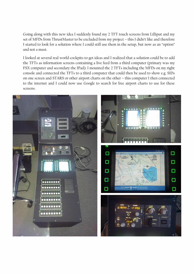
Going along with this new idea I suddenly found my 2 TFT touch screens from Lilliput and my
set of MFDs from ThrustMaster to be excluded from my project – this I didn’t like and therefore
I started to look for a solution where I could still use them in the setup, but now as an “option”
and not a must.
I looked at several real world cockpits to get ideas and I realized that a solution could be to add
the TFTs as information screens containing a live feed from a third computer (primary was my
FSX computer and secondary the IPad). I mounted the 2 TFTs including the MFDs on my right
console and connected the TFTs to a third computer that could then be used to show e.g. SIDs
on one screen and STARS or other airport charts on the other – this computer I then connected
to the internet and I could now use Google to search for free airport charts to use for these
screens.
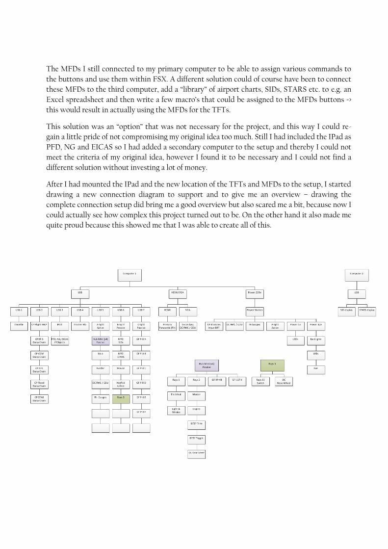
The MFDs I still connected to my primary computer to be able to assign various commands to
the buttons and use them within FSX. A different solution could of course have been to connect
these MFDs to the third computer, add a “library” of airport charts, SIDs, STARS etc. to e.g. an
Excel spreadsheet and then write a few macro’s that could be assigned to the MFDs buttons =>
this would result in actually using the MFDs for the TFTs.
This solution was an “option” that was not necessary for the project, and this way I could re-
gain a little pride of not compromising my original idea too much. Still I had included the IPad as
PFD, NG and EICAS so I had added a secondary computer to the setup and thereby I could not
meet the criteria of my original idea, however I found it to be necessary and I could not find a
different solution without investing a lot of money.
After I had mounted the IPad and the new location of the TFTs and MFDs to the setup, I started
drawing a new connection diagram to support and to give me an overview – drawing the
complete connection setup did bring me a good overview but also scared me a bit, because now I
could actually see how complex this project turned out to be. On the other hand it also made me
quite proud because this showed me that I was able to create all of this.
Conclusion
I had an amazing time building this rather complex home cockpit, and I discovered that even
though I am not a computer wizard or an engineer etc. I was still able to finish this project. I of
course had a lot of lessons learning throughout the project, but I am certain that I would not be
scared to dive into a similar project again.
It does take an incredible amount of time doing such a project, but for me it was just as much
fun to build the home cockpit as it is using it afterwards. One thing that I believe is very
important if you start a project like this, is to prioritize your time and concentrate on what is
important in your life => hereby I mean that if you are a family person, don’t forget your family! In
my case family always come first, then health, then the professional job that puts food on the
table and first then hobbies, fun etc.
I am very fortunate that I have a daughter (3½ years old) that is extremely interested in my
hobby, simply because it features a huge number of things (switches etc.) that can move, and she
really likes to go to my “office” and play. Quality time yes? ;-)
I also found that setting up some simple goals was a great way of keeping me going. Building or
going through a project with a long time schedule like this, did at times seem to be too much
and I found myself just wanted to tear the project apart and say “that was it – That was a too big and
complex project for me” but simply by setting small goals as e.g. creating the top panels for one of
the consoles or figuring out a way to support the TFTs etc.–gave me the sense of success and
that boosted my confidence and gave me more energy and devotion for sure.
I have already thought about potential upgrades to the setup as e.g. building a shell or mounting
a B737 overhead etc. but to be honest that will probably not happen – I have now finished the
project and the next step I think will be to take the home cockpit apart, and start all over with a
new design or a new project.
One thing is for sure – the TV is not the best solution for a display. Even though it is a 42”
plasma, the resolution is not high enough (my TV does not have HD resolution), so a future
solution will certainly be to add an HD projector providing a full 120” screen instead.
I would like to take this opportunity to thank all the people that have been a part of this project
– either as a sponsor, a contact or just an advisor. I am very fortunate to have all of you in my
network and I really appreciate your help greatly!
I would also like to thank www.Flightsim.com and www.DanSim.dk for publishing this article
which I hope could encourage other people to enter the flightsim community or even to start
other projects to add to the realism of the flightsim idea.