PROJECT FOR: PHASE 1 PHASE 2 - Dublin, Ohio,...
8
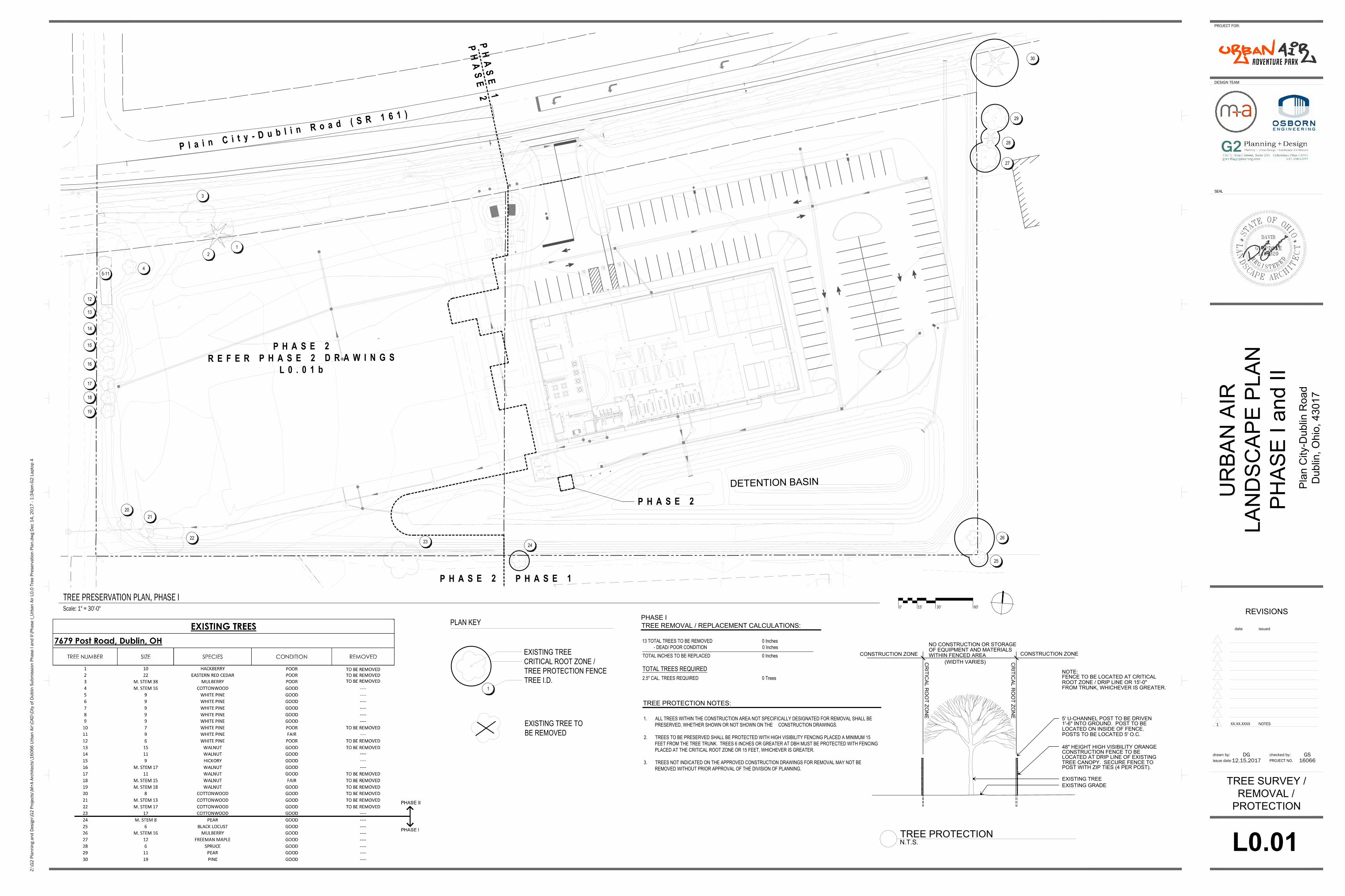
Scale: 1" = 30'-0" 0' 30' 15' 60' TREE PRESERVATION PLAN, PHASE I Plain City-Dublin Road (SR 161) L0.01 Z:\G2 Planning and Design\G2 Projects\M+A Architects\16066 Urban Air\CAD\City of Dublin Submission Phase I and II\Phase I_Urban Air L0.0 Tree Preservation Plan.dwg Dec 14, 2017 - 1:34pm-G2 Laptop 4 issue date 12.15.2017 PROJECT NO. 16066 date issued 1 XX.XX.XXXX NOTES SEAL URBAN AIR LANDSCAPE PLAN PHASE I and II Plan City-Dublin Road Dublin, Ohio, 43017 PROJECT FOR: DESIGN TEAM REVISIONS drawn by: DG checked by: GS 1 2 3 4 5-11 12 13 14 15 16 17 18 19 20 21 22 23 24 25 26 27 28 29 30 PLAN KEY EXISTING TREE CRITICAL ROOT ZONE / TREE PROTECTION FENCE TREE I.D. EXISTING TREE TO BE REMOVED 1 1. ALL TREES WITHIN THE CONSTRUCTION AREA NOT SPECIFICALLY DESIGNATED FOR REMOVAL SHALL BE PRESERVED, WHETHER SHOWN OR NOT SHOWN ON THE CONSTRUCTION DRAWINGS. 2. TREES TO BE PRESERVED SHALL BE PROTECTED WITH HIGH VISIBILITY FENCING PLACED A MINIMUM 15 FEET FROM THE TREE TRUNK. TREES 6 INCHES OR GREATER AT DBH MUST BE PROTECTED WITH FENCING PLACED AT THE CRITICAL ROOT ZONE OR 15 FEET, WHICHEVER IS GREATER. 3. TREES NOT INDICATED ON THE APPROVED CONSTRUCTION DRAWINGS FOR REMOVAL MAY NOT BE REMOVED WITHOUT PRIOR APPROVAL OF THE DIVISION OF PLANNING. TREE PROTECTION NOTES: 13 TOTAL TREES TO BE REMOVED 0 Inches - DEAD/ POOR CONDITION 0 Inches TOTAL INCHES TO BE REPLACED 0 Inches TOTAL TREES REQUIRED 2.5" CAL. TREES REQUIRED 0 Trees TREE REMOVAL / REPLACEMENT CALCULATIONS: TREE SURVEY / REMOVAL / PROTECTION EXISTING GRADE EXISTING TREE CONSTRUCTION FENCE TO BE 48" HEIGHT HIGH VISIBILITY ORANGE WITHIN FENCED AREA OF EQUIPMENT AND MATERIALS NO CONSTRUCTION OR STORAGE CONSTRUCTION ZONE CONSTRUCTION ZONE LOCATED AT DRIP LINE OF EXISTING TREE CANOPY. SECURE FENCE TO CRITICAL ROOT ZONE 1'-6" INTO GROUND. POST TO BE 5' U-CHANNEL POST TO BE DRIVEN LOCATED ON INSIDE OF FENCE. POSTS TO BE LOCATED 5' O.C. POST WITH ZIP TIES (4 PER POST). (WIDTH VARIES) CRITICAL ROOT ZONE FENCE TO BE LOCATED AT CRITICAL NOTE: ROOT ZONE / DRIP LINE OR 15'-0" FROM TRUNK, WHICHEVER IS GREATER. N.T.S. TREE PROTECTION DETENTION BASIN PHASE 1 PHASE 2 PHASE 2 PHASE 1 PHASE I PHASE 2 REFER PHASE 2 DRAWINGS L0.01b PHASE 2
Transcript of PROJECT FOR: PHASE 1 PHASE 2 - Dublin, Ohio,...
Scale: 1" = 30'-0" 0' 30'15' 60'
TREE PRESERVATION PLAN, PHASE I
P
la
in
C
ity
-D
u
b
lin
R
o
ad
(S
R
1
61
)
L0.01
Z:\G
2 Pl
anni
ng a
nd D
esig
n\G
2 Pr
ojec
ts\M
+A A
rchi
tect
s\16
066
Urba
n Ai
r\CA
D\C
ity o
f Dub
lin S
ubm
issi
on P
hase
I an
d II\
Phas
e I_
Urba
n Ai
r L0.
0 Tr
ee P
rese
rvat
ion
Plan
.dw
g D
ec 1
4, 2
017
- 1:3
4pm
-G2
Lapt
op 4
issue date 12.15.2017 PROJECT NO. 16066
date issued
1 XX.XX.XXXX NOTES
SEAL
UR
BA
N A
IR
LA
ND
SC
AP
E P
LA
N
PH
AS
E I a
nd
II
Plan C
ity-D
ublin R
oad
Dublin, O
hio, 43017
PROJECT FOR:
DESIGN TEAM
REVISIONS
drawn by: DG checked by: GS
1
2
3
4
5-11
12
13
14
15
16
17
18
19
20
21
22
23
24
25
26
27
28
29
30
PLAN KEY
EXISTING TREE
CRITICAL ROOT ZONE /
TREE PROTECTION FENCE
TREE I.D.
EXISTING TREE TO
BE REMOVED
1
1. ALL TREES WITHIN THE CONSTRUCTION AREA NOT SPECIFICALLY DESIGNATED FOR REMOVAL SHALL BE
PRESERVED, WHETHER SHOWN OR NOT SHOWN ON THE CONSTRUCTION DRAWINGS.
2. TREES TO BE PRESERVED SHALL BE PROTECTED WITH HIGH VISIBILITY FENCING PLACED A MINIMUM 15
FEET FROM THE TREE TRUNK. TREES 6 INCHES OR GREATER AT DBH MUST BE PROTECTED WITH FENCING
PLACED AT THE CRITICAL ROOT ZONE OR 15 FEET, WHICHEVER IS GREATER.
3. TREES NOT INDICATED ON THE APPROVED CONSTRUCTION DRAWINGS FOR REMOVAL MAY NOT BE
REMOVED WITHOUT PRIOR APPROVAL OF THE DIVISION OF PLANNING.
TREE PROTECTION NOTES:
13 TOTAL TREES TO BE REMOVED 0 Inches
- DEAD/ POOR CONDITION 0 Inches
TOTAL INCHES TO BE REPLACED 0 Inches
TOTAL TREES REQUIRED
2.5" CAL. TREES REQUIRED 0 Trees
TREE REMOVAL / REPLACEMENT CALCULATIONS:
TREE SURVEY /
REMOVAL /
PROTECTION
EXISTING GRADE
EXISTING TREE
CONSTRUCTION FENCE TO BE
48" HEIGHT HIGH VISIBILITY ORANGE
WITHIN FENCED AREA
OF EQUIPMENT AND MATERIALS
NO CONSTRUCTION OR STORAGE
CONSTRUCTION ZONECONSTRUCTION ZONE
LOCATED AT DRIP LINE OF EXISTING
TREE CANOPY. SECURE FENCE TO
CR
IT
IC
AL
R
OO
T Z
ON
E
1'-6" INTO GROUND. POST TO BE
5' U-CHANNEL POST TO BE DRIVEN
LOCATED ON INSIDE OF FENCE.
POSTS TO BE LOCATED 5' O.C.
POST WITH ZIP TIES (4 PER POST).
(WIDTH VARIES)
CR
IT
IC
AL
R
OO
T Z
ON
E
FENCE TO BE LOCATED AT CRITICAL
NOTE:
ROOT ZONE / DRIP LINE OR 15'-0"
FROM TRUNK, WHICHEVER IS GREATER.
N.T.S.
TREE PROTECTION
DETENTION BASIN
P
H
A
S
E
1
P
H
A
S
E
2
P H A S E 2 P H A S E 1
PHASE I
P H A S E 2
R E F E R P H A S E 2 D R A W I N G S
L 0 . 0 1 b
P H A S E 2
AutoCAD SHX Text
S
AutoCAD SHX Text
S
AutoCAD SHX Text
D
AutoCAD SHX Text
S
AutoCAD SHX Text
S
AutoCAD SHX Text
S
AutoCAD SHX Text
S
AutoCAD SHX Text
D
AutoCAD SHX Text
S
AutoCAD SHX Text
D
AutoCAD SHX Text
D
AutoCAD SHX Text
D
AutoCAD SHX Text
D
AutoCAD SHX Text
S
AutoCAD SHX Text
1401329
AutoCAD SHX Text
*
AutoCAD SHX Text
L
AutoCAD SHX Text
A
AutoCAD SHX Text
N
AutoCAD SHX Text
D
AutoCAD SHX Text
S
AutoCAD SHX Text
C
AutoCAD SHX Text
A
AutoCAD SHX Text
P
AutoCAD SHX Text
E
AutoCAD SHX Text
A
AutoCAD SHX Text
R
AutoCAD SHX Text
C
AutoCAD SHX Text
H
AutoCAD SHX Text
I
AutoCAD SHX Text
T
AutoCAD SHX Text
E
AutoCAD SHX Text
C
AutoCAD SHX Text
T
AutoCAD SHX Text
*
AutoCAD SHX Text
S
AutoCAD SHX Text
T
AutoCAD SHX Text
A
AutoCAD SHX Text
T
AutoCAD SHX Text
E
AutoCAD SHX Text
O
AutoCAD SHX Text
F
AutoCAD SHX Text
O
AutoCAD SHX Text
H
AutoCAD SHX Text
I
AutoCAD SHX Text
O
AutoCAD SHX Text
R
AutoCAD SHX Text
E
AutoCAD SHX Text
G
AutoCAD SHX Text
I
AutoCAD SHX Text
S
AutoCAD SHX Text
T
AutoCAD SHX Text
E
AutoCAD SHX Text
R
AutoCAD SHX Text
E
AutoCAD SHX Text
D
AutoCAD SHX Text
GUAPPONE
AutoCAD SHX Text
C.
AutoCAD SHX Text
DAVID

Scale: 1" = 30'-0" 0' 30'15' 60'
TREE PRESERVATION PLAN, PHASE II
P
la
in
C
ity
-D
u
b
lin
R
o
ad
(S
R
1
61
)
L0.01b
Z:\G
2 Pl
anni
ng a
nd D
esig
n\G
2 Pr
ojec
ts\M
+A A
rchi
tect
s\16
066
Urba
n Ai
r\CA
D\C
ity o
f Dub
lin S
ubm
issi
on P
hase
I an
d II\
Phas
e II_
Urba
n Ai
r L0.
0 Tr
ee P
rese
rvat
ion
Plan
.dw
g D
ec 1
4, 2
017
- 1:3
7pm
-G2
Lapt
op 4
issue date 12.15.2017 PROJECT NO. 16066
date issued
1 XX.XX.XXXX NOTES
SEAL
UR
BA
N A
IR
LA
ND
SC
AP
E P
LA
N
PH
AS
E I a
nd
II
Plan C
ity-D
ublin R
oad
Dublin, O
hio, 43017
PROJECT FOR:
DESIGN TEAM
REVISIONS
drawn by: DG checked by: GS
1
2
3
4
5-11
12
13
14
15
16
17
18
19
20
21
22
23
24
25
26
27
28
29
30
PLAN KEY
EXISTING TREE
CRITICAL ROOT ZONE /
TREE PROTECTION FENCE
TREE I.D.
EXISTING TREE TO
BE REMOVED
1
1. ALL TREES WITHIN THE CONSTRUCTION AREA NOT SPECIFICALLY DESIGNATED FOR REMOVAL SHALL BE
PRESERVED, WHETHER SHOWN OR NOT SHOWN ON THE CONSTRUCTION DRAWINGS.
2. TREES TO BE PRESERVED SHALL BE PROTECTED WITH HIGH VISIBILITY FENCING PLACED A MINIMUM 15
FEET FROM THE TREE TRUNK. TREES 6 INCHES OR GREATER AT DBH MUST BE PROTECTED WITH FENCING
PLACED AT THE CRITICAL ROOT ZONE OR 15 FEET, WHICHEVER IS GREATER.
3. TREES NOT INDICATED ON THE APPROVED CONSTRUCTION DRAWINGS FOR REMOVAL MAY NOT BE
REMOVED WITHOUT PRIOR APPROVAL OF THE DIVISION OF PLANNING.
TREE PROTECTION NOTES:
TREE SURVEY /
REMOVAL /
PROTECTION
EXISTING GRADE
EXISTING TREE
CONSTRUCTION FENCE TO BE
48" HEIGHT HIGH VISIBILITY ORANGE
WITHIN FENCED AREA
OF EQUIPMENT AND MATERIALS
NO CONSTRUCTION OR STORAGE
CONSTRUCTION ZONECONSTRUCTION ZONE
LOCATED AT DRIP LINE OF EXISTING
TREE CANOPY. SECURE FENCE TO
CR
IT
IC
AL
R
OO
T Z
ON
E
1'-6" INTO GROUND. POST TO BE
5' U-CHANNEL POST TO BE DRIVEN
LOCATED ON INSIDE OF FENCE.
POSTS TO BE LOCATED 5' O.C.
POST WITH ZIP TIES (4 PER POST).
(WIDTH VARIES)
CR
IT
IC
AL
R
OO
T Z
ON
E
FENCE TO BE LOCATED AT CRITICAL
NOTE:
ROOT ZONE / DRIP LINE OR 15'-0"
FROM TRUNK, WHICHEVER IS GREATER.
N.T.S.
TREE PROTECTION
DETENTION BASIN
P
H
A
S
E
1
P
H
A
S
E
2
P H A S E 2 P H A S E 1
P H A S E 1
R E F E R P H A S E 1 D R A W I N G S
L 0 . 0 1
13 TOTAL TREES TO BE REMOVED 180 Inches
- DEAD/ POOR CONDITION -83 Inches
TOTAL INCHES TO BE REPLACED 97 Inches
TOTAL TREES REQUIRED
2.5" CAL. TREES REQUIRED 39 Trees
(97 / 2.5" = 38.8)
TREE REMOVAL / REPLACEMENT CALCULATIONS:
PHASE II
P H A S E 2
AutoCAD SHX Text
S
AutoCAD SHX Text
S
AutoCAD SHX Text
D
AutoCAD SHX Text
S
AutoCAD SHX Text
S
AutoCAD SHX Text
S
AutoCAD SHX Text
S
AutoCAD SHX Text
D
AutoCAD SHX Text
S
AutoCAD SHX Text
D
AutoCAD SHX Text
D
AutoCAD SHX Text
D
AutoCAD SHX Text
D
AutoCAD SHX Text
S
AutoCAD SHX Text
1401329
AutoCAD SHX Text
*
AutoCAD SHX Text
L
AutoCAD SHX Text
A
AutoCAD SHX Text
N
AutoCAD SHX Text
D
AutoCAD SHX Text
S
AutoCAD SHX Text
C
AutoCAD SHX Text
A
AutoCAD SHX Text
P
AutoCAD SHX Text
E
AutoCAD SHX Text
A
AutoCAD SHX Text
R
AutoCAD SHX Text
C
AutoCAD SHX Text
H
AutoCAD SHX Text
I
AutoCAD SHX Text
T
AutoCAD SHX Text
E
AutoCAD SHX Text
C
AutoCAD SHX Text
T
AutoCAD SHX Text
*
AutoCAD SHX Text
S
AutoCAD SHX Text
T
AutoCAD SHX Text
A
AutoCAD SHX Text
T
AutoCAD SHX Text
E
AutoCAD SHX Text
O
AutoCAD SHX Text
F
AutoCAD SHX Text
O
AutoCAD SHX Text
H
AutoCAD SHX Text
I
AutoCAD SHX Text
O
AutoCAD SHX Text
R
AutoCAD SHX Text
E
AutoCAD SHX Text
G
AutoCAD SHX Text
I
AutoCAD SHX Text
S
AutoCAD SHX Text
T
AutoCAD SHX Text
E
AutoCAD SHX Text
R
AutoCAD SHX Text
E
AutoCAD SHX Text
D
AutoCAD SHX Text
GUAPPONE
AutoCAD SHX Text
C.
AutoCAD SHX Text
DAVID

LANDSCAPE PLAN
Scale: 1" = 30'-0" 0' 30'15' 60'
LANDSCAPE PLAN, PHASE I
1
CODED NOTES
L1.01
PARKING LOT (±38,892 SF)
REQUIREMENT 153.133 B(2)
(100 SF OF PAVEMENT MUST HAVE 5 SF OF LANDSCAPE)
1,945 SF LANDSCAPE REQUIRED.
3,296 SF PROVIDED
2
PARKING LOT
REQUIREMENT 153.133 B
EACH LANDSCAPE ISLAND MUST BE AT LEAST 8' WIDE
AND A MIN. OF 112 SF (153.133 B (2A))
MUST INCLUDE 1 TREE PER ISLAND
STREET TREE REQUIREMENT
25' O.C. MAX - (153.134 1C)
3
4
PARKING LOT SCREEN
1 TREE 40' O.C.
CONTINUOUS SHRUB ROW - 3.5' HT.
(APPENDIX B)
10' BUFFER - 6' HT
SHRUBS + TREES
TREES 40' O.C.
APPENDIX A
(1 TREE PER 40 LF = 9 TREES REQUIRED)
9 TREES PROVIDED
5
6
GROUND COVERAGE (64,401 SF)
REQUIREMENT 153.133 B (3A)
1 TREE FOR EVERY 5,000 SF OF GROUND COVERAGE REQUIRED
13 TREES REQUIRED
13 TREES PROVIDED
7
BUILDING LANDSCAPE
REQUIREMENT 153.133 D(2B)
PROVIDE 2% LANDSCAPE ZONE OF THE TOTAL BUILDING COVERAGE
20,000 SF BUILDING COVERAGE = 400 SF OF LA REQUIRED -
1,070 SF PROVIDED
8
9
Z:\G
2 Pl
anni
ng a
nd D
esig
n\G
2 Pr
ojec
ts\M
+A A
rchi
tect
s\16
066
Urba
n Ai
r\CA
D\C
ity o
f Dub
lin S
ubm
issi
on P
hase
I an
d II\
Phas
e I_
Urba
n Ai
r L1.
0 LA
ND
SCAP
E PL
AN.d
wg
Dec
15,
201
7 - 1
1:17
am-G
2 La
ptop
4
issue date 12.15.2017 PROJECT NO. 16066
date issued
1 XX.XX.XXXX NOTES
SEAL
UR
BA
N A
IR
LA
ND
SC
AP
E P
LA
N
PH
AS
E I a
nd
II
Plan C
ity-D
ublin R
oad
Dublin, O
hio, 43017
PROJECT FOR:
DESIGN TEAM
REVISIONS
drawn by: DG checked by: GS
DETENTION BASIN
P
la
in
C
ity
-D
u
b
lin
R
o
a
d
(S
R
1
6
1
)
2
2
2
2
2
2
7
4
5
5
7
7
7
7
7
7
8
8
6
7
7
7
SCREEN UTILITIES - FENCE, WALL, HEDGE, MOUND
1 FT HIGHER THAN STRUCTURE BUT NOT EXCEED
12' HT. 153.133 C(1)
TREE REPLACEMENT (REFER L0.01)
0 TREES REQUIRED
0 TREES PROVIDED
1. Stake all bed lines and tree locations for the Landscape Architect's review prior to installation. All
planting procedures are subject to the review of the Landscape Architect and the Contractor shall
correct any deficiencies found at no additional cost to the Owner.
2. Secure plant material as specified on plans. In the event that plant materials specified are not
available, contact Landscape Architect for approved substitutions. No substitutions for plant
materials will be allowed without prior written approval by the Landscape Architect.
3. Verify that all planting products, plant material, and plant quantities delivered to the site match what
is indicated on the plans and specifications.
4. Protect all plant material during delivery to prevent damage to root balls, trunks, branches and the
desiccation of leaves. Protect all plant material during shipping with shade cloth or ship with
enclosed transport. Maintain protections and health of plant material stored on site. Handle all trees
with nylon straps. No chains or cables will be allowed. Remove unacceptable plant material
immediately from the site.
5. All plant material shall be nursery grown, well formed, true to species, hardened off with vigorous
root systems, full crown and canopies, and free from disease, pests and insects, and defects such as
knots, sun scald, windburn, leaf dis-coloration, irregular branching or injuries.
6. All root balls shall conform to the size standards set forth in “American Standards for Nursery Stock”.
7. All plant material delivered to the site is subject to the review of the Landscape Architect before,
during and after installation.
8. Test fill all tree and planting pits with water, prior to planting, to assure proper soil percolation. Pits
which do not adequately drain shall be further excavated to a depth sufficient for drainage to occur
and/or backfilled with suitable drainage gravel. No allowances shall be made for plant material loss
due to improper drainage. Contractor shall replace lost plant material with same size and species at
no additional cost to Owner.
9. All plant materials, including relocated plant material, shall be planted in a professional manner
typical to the industry standards of the area to assure complete survivability of all installed plant
materials as well as to provide an aesthetically approved project. Contractor shall refer to the
planting details for minimum size and width of planting pits and beds, guying and staking, mulching,
and other planting requirements.
10. All planting areas shall be weed free prior to planting installation.
11. Remove all planting and landscape debris from the project site and sweep and wash clean all paved
and finished surfaces affected by the landscape installation.
L A N D S C A P E N O T E S
REFER TO SHEET:
L1.02 - COURTYARD LANDSCAPE PLAN
L1.03 - COURTYARD HARDSCAPE PLAN
SPACINGCOND.SIZEBOT. NAME/COMMON NAMECODE NOTES
Ginkgo Biloba 'Princeton Sentry'GI BI B+B MATCH FORM
PER PLAN
Princeton Sentry Ginkgo
SHRUBS
36" HT.
B+B PER PLAN
JU SG
MATCH FORM
L2.01
A
EVERGREEN TREES
Picea abiesPI AB 6' HT. B+B MATCH FORM
PER PLAN
Norway Spruce
L2.01
A
Juniperus chinensis 'Sea Green'
Sea Green Juniper
18" HT.PER PLAN
IT LH
MATCH FORM
Itea virginica 'Sprich'
Little Henry Itea
#3 CONT.
*NOTE: FIELD VERIFY LOCATION AND
DEPTHS OF ALL UTILITIES.
HAND EXCAVATE ALL PLANTING PITS.
Additional Planting Notes
1. All groundcovers and perennials to be
planted during the spring planting
window. Fall groundcover and perennial
plantings will not be accepted.
Coordinate planting times with owners
representative to increase success of
groundcover and perennial plantings
(QUANTITY)
(SPECIES)
PLANT TAG
XX XX
Platanus xacerfolia 'Bloodgood'PL AC B+B MATCH FORM
PER PLAN
Bloodgood London Planetree
Acer saccharum 'Wright Brothers'AC SA B+B
PER PLAN
Wright Brothers Maple
P L A N T L I S T (ALL PLANT MATERIAL TO BE IRRIGATED)
DECIDUOUS TREES
QTY.
N/APER PLAN
LI BB Lirope muscari 'Big Blue'
Big Blue Liriope
#1 CONT.
18" O.C.
TH SM Thuja occidentalis 'Smaragd'
Emerald Green Arborvitae
PER PLAN MATCH FORM
6' HT.
B+B
3
PI AB
43
TH SM
1
QU RU
2
AC SA
TA DE Taxus xmedia 'Densiformis'
Dense Yew
PER PLAN MATCH FORM
24" HT.
B+B
7
Quercus bicolorQU BI B+B MATCH FORM
PER PLAN
Swamp White Oak
Carpinus betulus 'Frans Fontaine'CA BE B+B MATCH FORM
PER PLAN
Frans Fontaine Hornbeam
2.5" CAL. MATCH FORM
Quercus rubraQU RU B+B MATCH FORM
PER PLAN
Red Oak
1
PERENNIALS/GRASSES
22
TH SM
7
GI BI
3
PL AC
1
AC SA
3
PL AC
2
AC SA
3
PI AB
36
TH SM
1
QU BI
2
PL AC
113
JU SG
56
JU SG
6
LI BB
9
TA DE
38
IT LH
64
TA DE
38
IT LH
9
LI BB
L2.01
B1
L2.01
B2
2.5" CAL.
2.5" CAL.
2.5" CAL.
2.5" CAL.
2.5" CAL.
5
5
7
GI BI
6
CA BE
11
AM GR
4
4
4
4
4
4
7
7
3
SMALL ORNAMENTAL TREES
B+B MATCH FORM
PER PLAN2" CAL.
Autumn Brilliance Serviceberry
Amelanchier x grandiflora 'Autumn Brilliance'AM GR
L2.01
A
39
TH SM
(140)
(15)
(73)
(76)
(169)
(6)
(11)
(14)
(5)
(8)
(1)
(6)
(1)
P H A S E 2
P H A S E 2
R E F E R P H A S E 2 D R A W I N G S
L 1 . 0 1 b
4
46
AutoCAD SHX Text
S
AutoCAD SHX Text
S
AutoCAD SHX Text
S
AutoCAD SHX Text
D
AutoCAD SHX Text
S
AutoCAD SHX Text
D
AutoCAD SHX Text
D
AutoCAD SHX Text
D
AutoCAD SHX Text
D
AutoCAD SHX Text
S
AutoCAD SHX Text
1401329
AutoCAD SHX Text
*
AutoCAD SHX Text
L
AutoCAD SHX Text
A
AutoCAD SHX Text
N
AutoCAD SHX Text
D
AutoCAD SHX Text
S
AutoCAD SHX Text
C
AutoCAD SHX Text
A
AutoCAD SHX Text
P
AutoCAD SHX Text
E
AutoCAD SHX Text
A
AutoCAD SHX Text
R
AutoCAD SHX Text
C
AutoCAD SHX Text
H
AutoCAD SHX Text
I
AutoCAD SHX Text
T
AutoCAD SHX Text
E
AutoCAD SHX Text
C
AutoCAD SHX Text
T
AutoCAD SHX Text
*
AutoCAD SHX Text
S
AutoCAD SHX Text
T
AutoCAD SHX Text
A
AutoCAD SHX Text
T
AutoCAD SHX Text
E
AutoCAD SHX Text
O
AutoCAD SHX Text
F
AutoCAD SHX Text
O
AutoCAD SHX Text
H
AutoCAD SHX Text
I
AutoCAD SHX Text
O
AutoCAD SHX Text
R
AutoCAD SHX Text
E
AutoCAD SHX Text
G
AutoCAD SHX Text
I
AutoCAD SHX Text
S
AutoCAD SHX Text
T
AutoCAD SHX Text
E
AutoCAD SHX Text
R
AutoCAD SHX Text
E
AutoCAD SHX Text
D
AutoCAD SHX Text
GUAPPONE
AutoCAD SHX Text
C.
AutoCAD SHX Text
DAVID

LANDSCAPE PLAN
Scale: 1" = 30'-0" 0' 30'15' 60'
LANDSCAPE PLAN, PHASE II
1
CODED NOTES
L1.01b
PARKING LOT (±24,091 SF)
REQUIREMENT 153.133 B(2)
(100 SF OF PAVEMENT MUST HAVE 5 SF OF LANDSCAPE)
1,205 SF LANDSCAPE REQUIRED.
1,232 SF PROVIDED
2
PARKING LOT
REQUIREMENT 153.133 B
EACH LANDSCAPE ISLAND MUST BE AT LEAST 8' WIDE
AND A MIN. OF 112 SF (153.133 B (2A))
MUST INCLUDE 1 TREE PER ISLAND
STREET TREE REQUIREMENT
25' O.C. MAX - (153.134 1C)
3
4
PARKING LOT SCREEN
1 TREE 40' O.C.
CONTINUOUS SHRUB ROW - 3.5' HT.
(APPENDIX B)
10' BUFFER - 6' HT
SHRUBS + TREES
TREES 40' O.C.
APPENDIX A
5
6
GROUND COVERAGE (50,500 SF)
REQUIREMENT 153.133 B (3A)
1 TREE FOR EVERY 5,000 SF OF GROUND COVERAGE REQUIRED
11 TREES REQUIRED
11 TREES PROVIDED
7
BUILDING LANDSCAPE
REQUIREMENT 153.133 D(2B)
PROVIDE 2% LANDSCAPE ZONE OF THE TOTAL BUILDING COVERAGE
20,000 SF BUILDING COVERAGE = 400 SF OF LA REQUIRED -
2,100 SF PROVIDED
8
9
Z:\G
2 Pl
anni
ng a
nd D
esig
n\G
2 Pr
ojec
ts\M
+A A
rchi
tect
s\16
066
Urba
n Ai
r\CA
D\C
ity o
f Dub
lin S
ubm
issi
on P
hase
I an
d II\
Phas
e II_
Urba
n Ai
r L1.
0 LA
ND
SCAP
E PL
AN.d
wg
Dec
15,
201
7 - 1
2:38
pm-G
2 La
ptop
4
issue date 12.15.2017 PROJECT NO. 16066
date issued
1 XX.XX.XXXX NOTES
SEAL
UR
BA
N A
IR
LA
ND
SC
AP
E P
LA
N
PH
AS
E I a
nd
II
Plan C
ity-D
ublin R
oad
Dublin, O
hio, 43017
PROJECT FOR:
DESIGN TEAM
REVISIONS
drawn by: DG checked by: GS
DETENTION BASIN
P
la
in
C
ity
-D
u
b
lin
R
o
a
d
(S
R
1
6
1
)
SCREEN UTILITIES - FENCE, WALL, HEDGE, MOUND
1 FT HIGHER THAN STRUCTURE BUT NOT EXCEED
12' HT. 153.133 C(1)
TREE REPLACEMENT (REFER L0.01)
39 TREES REQUIRED
39 TREES PROVIDED
1. Stake all bed lines and tree locations for the Landscape Architect's review prior to installation. All
planting procedures are subject to the review of the Landscape Architect and the Contractor shall
correct any deficiencies found at no additional cost to the Owner.
2. Secure plant material as specified on plans. In the event that plant materials specified are not
available, contact Landscape Architect for approved substitutions. No substitutions for plant
materials will be allowed without prior written approval by the Landscape Architect.
3. Verify that all planting products, plant material, and plant quantities delivered to the site match what
is indicated on the plans and specifications.
4. Protect all plant material during delivery to prevent damage to root balls, trunks, branches and the
desiccation of leaves. Protect all plant material during shipping with shade cloth or ship with
enclosed transport. Maintain protections and health of plant material stored on site. Handle all trees
with nylon straps. No chains or cables will be allowed. Remove unacceptable plant material
immediately from the site.
5. All plant material shall be nursery grown, well formed, true to species, hardened off with vigorous
root systems, full crown and canopies, and free from disease, pests and insects, and defects such as
knots, sun scald, windburn, leaf dis-coloration, irregular branching or injuries.
6. All root balls shall conform to the size standards set forth in “American Standards for Nursery Stock”.
7. All plant material delivered to the site is subject to the review of the Landscape Architect before,
during and after installation.
8. Test fill all tree and planting pits with water, prior to planting, to assure proper soil percolation. Pits
which do not adequately drain shall be further excavated to a depth sufficient for drainage to occur
and/or backfilled with suitable drainage gravel. No allowances shall be made for plant material loss
due to improper drainage. Contractor shall replace lost plant material with same size and species at
no additional cost to Owner.
9. All plant materials, including relocated plant material, shall be planted in a professional manner
typical to the industry standards of the area to assure complete survivability of all installed plant
materials as well as to provide an aesthetically approved project. Contractor shall refer to the
planting details for minimum size and width of planting pits and beds, guying and staking, mulching,
and other planting requirements.
10. All planting areas shall be weed free prior to planting installation.
11. Remove all planting and landscape debris from the project site and sweep and wash clean all paved
and finished surfaces affected by the landscape installation.
L A N D S C A P E N O T E S
REFER TO SHEET:
L1.02 - COURTYARD LANDSCAPE PLAN
L1.03 - COURTYARD HARDSCAPE PLAN
SPACINGCOND.SIZEBOT. NAME/COMMON NAMECODE NOTES
Ginkgo Biloba 'Princeton Sentry'GI BI B+B MATCH FORM
PER PLAN
Princeton Sentry Ginkgo
SHRUBS
36" HT.B+B PER PLAN
JU SG
MATCH FORM
L2.01
A
Juniperus chinensis 'Sea Green'
Sea Green Juniper
18" HT.PER PLAN
IT LH
MATCH FORM
Itea virginica 'Sprich'
Little Henry Itea
#3 CONT.
*NOTE: FIELD VERIFY LOCATION AND
DEPTHS OF ALL UTILITIES.
HAND EXCAVATE ALL PLANTING PITS.
Additional Planting Notes
1. All groundcovers and perennials to be
planted during the spring planting
window. Fall groundcover and perennial
plantings will not be accepted.
Coordinate planting times with owners
representative to increase success of
groundcover and perennial plantings
(QUANTITY)
(SPECIES)
PLANT TAG
XX XX
Platanus xacerfolia 'Bloodgood'PL AC B+B MATCH FORM
PER PLAN
Bloodgood London Planetree
Acer saccharum 'Wright Brothers'AC SA B+B
PER PLAN
Wright Brothers Maple
P L A N T L I S T (ALL PLANT MATERIAL TO BE IRRIGATED)
DECIDUOUS TREES
QTY.
N/APER PLAN
LI BB Lirope muscari 'Big Blue'
Big Blue Liriope
#1 CONT.
18" O.C.
TA DE Taxus xmedia 'Densiformis'
Dense Yew
PER PLAN MATCH FORM
24" HT.
B+B
Quercus bicolorQU BI B+B MATCH FORM
PER PLAN
Swamp White Oak
Carpinus betulus 'Frans Fontaine'CA BE B+B MATCH FORM
PER PLAN
Frans Fontaine Hornbeam
Acer rubrum 'Franksred'AC RU B+B
PER PLAN
Red Sunset Maple
2.5" CAL.
MATCH FORM
MATCH FORM
Quercus rubraQU RU B+B MATCH FORM
PER PLAN
Red Oak
1
PERENNIALS/GRASSES
L2.01
B1
L2.01
B2
2.5" CAL.
2.5" CAL.
2.5" CAL.
2.5" CAL.
2.5" CAL.
2.5" CAL.
P
H
A
S
E
II
P
H
A
S
E
I
PH
AS
E II
PH
AS
E I
2
2
2
4
4
4
4
4
4
4
4
4
4
4
4
7
7
7
7
7
7
7
7
7
7
7
3
13
AM GR
8
8
39
TA DE
122
IT LH
30
IT LH
6
LI BB
9
LI BB
6
AC RU
6
PL AC
1
PL AC
2
CA BE
3
PL AC
14
GI BI
161
JU SG
5
AC SA
8
QU RU
4
PL AC
8
QU BI
8
QU RU
SMALL ORNAMENTAL TREES
B+B MATCH FORM
PER PLAN2" CAL.
Autumn Brilliance Serviceberry
Amelanchier x grandiflora 'Autumn Brilliance'AM GR
L2.01
A
(13)
(15)
(5)
(6)
(2)
(14)
(14)
(8)
(16)
(152)
(161)
(39)
4
6
P H A S E 1
R E F E R P H A S E 1 D R A W I N G S
L 1 . 0 1
INSTALLED IN
PHASE 1
6
4
AutoCAD SHX Text
S
AutoCAD SHX Text
S
AutoCAD SHX Text
S
AutoCAD SHX Text
D
AutoCAD SHX Text
S
AutoCAD SHX Text
D
AutoCAD SHX Text
D
AutoCAD SHX Text
D
AutoCAD SHX Text
D
AutoCAD SHX Text
S
AutoCAD SHX Text
1401329
AutoCAD SHX Text
*
AutoCAD SHX Text
L
AutoCAD SHX Text
A
AutoCAD SHX Text
N
AutoCAD SHX Text
D
AutoCAD SHX Text
S
AutoCAD SHX Text
C
AutoCAD SHX Text
A
AutoCAD SHX Text
P
AutoCAD SHX Text
E
AutoCAD SHX Text
A
AutoCAD SHX Text
R
AutoCAD SHX Text
C
AutoCAD SHX Text
H
AutoCAD SHX Text
I
AutoCAD SHX Text
T
AutoCAD SHX Text
E
AutoCAD SHX Text
C
AutoCAD SHX Text
T
AutoCAD SHX Text
*
AutoCAD SHX Text
S
AutoCAD SHX Text
T
AutoCAD SHX Text
A
AutoCAD SHX Text
T
AutoCAD SHX Text
E
AutoCAD SHX Text
O
AutoCAD SHX Text
F
AutoCAD SHX Text
O
AutoCAD SHX Text
H
AutoCAD SHX Text
I
AutoCAD SHX Text
O
AutoCAD SHX Text
R
AutoCAD SHX Text
E
AutoCAD SHX Text
G
AutoCAD SHX Text
I
AutoCAD SHX Text
S
AutoCAD SHX Text
T
AutoCAD SHX Text
E
AutoCAD SHX Text
R
AutoCAD SHX Text
E
AutoCAD SHX Text
D
AutoCAD SHX Text
GUAPPONE
AutoCAD SHX Text
C.
AutoCAD SHX Text
DAVID

COURTYARD
LANDSCAPE PLAN
Scale: 1" = 10'-0" 0' 10'5' 20'
COURTYARD ENLARGEMENT PLAN
L1.02
Z:\G
2 Pl
anni
ng a
nd D
esig
n\G
2 Pr
ojec
ts\M
+A A
rchi
tect
s\16
066
Urba
n Ai
r\CA
D\C
ity o
f Dub
lin S
ubm
issi
on P
hase
I an
d II\
Urba
n Ai
r L1.
02 L
AYOU
T AN
D M
ATER
IALS
PLA
N E
NLA
RGEM
ENT.
dwg
Dec
14,
201
7 - 1
:46p
m-G
2 La
ptop
4
issue date 12.15.2017 PROJECT NO. 16066
date issued
1 XX.XX.XXXX NOTES
SEAL
UR
BA
N A
IR
LA
ND
SC
AP
E P
LA
N
PH
AS
E I a
nd
II
Plan C
ity-D
ublin R
oad
Dublin, O
hio, 43017
PROJECT FOR:
DESIGN TEAM
REVISIONS
drawn by: DG checked by: GS
SPACINGCOND.SIZEBOT. NAME/COMMON NAMECODE
P L A N T L I S T (ALL PLANT MATERIAL TO BE IRRIGATED)
NOTES
DECIDUOUS TREES
SHRUBS
S I T E A N D M A T E R I A L N O T E S
1.
TURF
2.
LANDSCAPE BED - PROVIDED 3" DEPTH HARDWOOD MULCH
PERENNIALS/GRASSES
*NOTE: FIELD VERIFY LOCATION AND DEPTHS OF ALL UTILITIES.
HAND EXCAVATE ALL PLANTING PITS.
Additional Planting Notes
1. All groundcovers and perennials to be planted during the spring planting window. Fall
groundcover and perennial plantings will not be accepted. Coordinate planting times with owners
representative to increase success of groundcover and perennial plantings
(QUANTITY)
(SPECIES)
PLANT TAG
XX XX
1
8
LI BB
2
AM CA
Acer griseumAC GR 8' HT. B+B MULTI-STEM
PER PLAN
Paperbark Maple
695
HE CM
TA EV Taxus xmedia 'Everlow'
Everlow Yew
PER PLAN MATCH FORM18" SPRD.#3 CONT.
21
TA EV
N/APER PLAN
LI BB Lirope muscari 'Big Blue'
Big Blue Liriope
#1 CONT.
Amelanchier canadensis 'Glenn Form'AM CA 8' HT. B+B MULTI-STEM
PER PLAN
Rainbow Pillar Serviceberry
N/APER PLAN
HE CM
9" O.C.
Heuchera 'Caramel'
Caramel Coral Bells
#2 CONT.
327
LI BB
WE SU Weigela florida 'Sunset'
My Monet Sunset Weigela
PER PLAN MATCH FORM18" SPRD.#3 CONT.
8
LI BB
13
TA EV
162
HE CM
1
AC GR
N/APER PLAN
SP HE
24" O.C.
Sporobolus heterolepsis
Prairie Dropseed
#3 CONT.
9" O.C.
221
WE SU
328
HE CM
Liquidambar styraciflua 'Slender Silhoutte'LI ST 2.5" CAL. B+B MATCH FORM
PER PLAN
Slender Sllhouette Sweetgum
4
LI ST
327
LI BB
37
HE CM
102
SP HE
2.
2.
2.
1.
1.
1.
1.
2.
2.
2.
37
HE CM
L2.01
A
L2.01
B2
L2.01
B1
N/APER PLAN
HO SP
24" O.C.
Hosta ‘Sun Power’
Hosta
#2 CONT.
30
HO SP
PH
AS
E II
PH
AS
E I
PH
AS
E II
PH
AS
E I
PHASE II
(1)
(2)
(4)
(34)
(221)
(670)
(1,259)
(102)
(30)
20
TH SM
TH SM Thuja occidentalis 'Smaragd'
Emerald Green Arborvitae
PER PLAN MATCH FORM
6' HT.
B+B
(20)
AutoCAD SHX Text
S
AutoCAD SHX Text
1401329
AutoCAD SHX Text
*
AutoCAD SHX Text
L
AutoCAD SHX Text
A
AutoCAD SHX Text
N
AutoCAD SHX Text
D
AutoCAD SHX Text
S
AutoCAD SHX Text
C
AutoCAD SHX Text
A
AutoCAD SHX Text
P
AutoCAD SHX Text
E
AutoCAD SHX Text
A
AutoCAD SHX Text
R
AutoCAD SHX Text
C
AutoCAD SHX Text
H
AutoCAD SHX Text
I
AutoCAD SHX Text
T
AutoCAD SHX Text
E
AutoCAD SHX Text
C
AutoCAD SHX Text
T
AutoCAD SHX Text
*
AutoCAD SHX Text
S
AutoCAD SHX Text
T
AutoCAD SHX Text
A
AutoCAD SHX Text
T
AutoCAD SHX Text
E
AutoCAD SHX Text
O
AutoCAD SHX Text
F
AutoCAD SHX Text
O
AutoCAD SHX Text
H
AutoCAD SHX Text
I
AutoCAD SHX Text
O
AutoCAD SHX Text
R
AutoCAD SHX Text
E
AutoCAD SHX Text
G
AutoCAD SHX Text
I
AutoCAD SHX Text
S
AutoCAD SHX Text
T
AutoCAD SHX Text
E
AutoCAD SHX Text
R
AutoCAD SHX Text
E
AutoCAD SHX Text
D
AutoCAD SHX Text
GUAPPONE
AutoCAD SHX Text
C.
AutoCAD SHX Text
DAVID

31'-6"31'-6"
10' 14'-6" 5'10'14'-6"5'
9'-7"4'
9'-7"4'
7' 7'-6" 7'-6" 7'7' 9'-6"
4' 16'-6" 16'-6" 4'
4'18'-6"
2'
7'-1"
COURTYARD
HARDSCAPE PLAN
Scale: 1" = 10'-0" 0' 10'5' 20'
COURTYARD HARDSCAPE PLAN
L1.03
Z:\G
2 Pl
anni
ng a
nd D
esig
n\G
2 Pr
ojec
ts\M
+A A
rchi
tect
s\16
066
Urba
n Ai
r\CA
D\C
ity o
f Dub
lin S
ubm
issi
on P
hase
I an
d II\
Urba
n Ai
r L1.
03 H
ards
cape
Pla
n En
larg
emen
t.dw
g D
ec 1
5, 2
017
- 12:
24pm
-G2
Lapt
op 4
issue date 12.15.2017 PROJECT NO. 16066
date issued
1 XX.XX.XXXX NOTES
SEAL
UR
BA
N A
IR
LA
ND
SC
AP
E P
LA
N
PH
AS
E I a
nd
II
Plan C
ity-D
ublin R
oad
Dublin, O
hio, 43017
PROJECT FOR:
DESIGN TEAM
REVISIONS
drawn by: DG checked by: GS
S I T E A N D M A T E R I A L N O T E S
ALIGN WITH ARCHITECTURE
CONCRETE PAVEMENT - SEE DETAILS C, D, E, & H, SHEET L2.01
BUFF WASH FINISH WITH SAW CUT JOINTS
RAISED PLANTER
L2.02A
SEE DETAIL A, SHEET L2.02
1
2
3
1
1
1
1
1
3
2
3
2
CODED NOTES
L2
.0
2
C
BIKE RACK (TYP. OF 7)
SEE DETAIL K, SHEET L2.01
CABLE RAIL FENCE
SEE DETAIL J, SHEET L2.01
L2.02
D
CONCRETE SEATING BLOCK, TYP (4)
SEE DETAIL B, SHEET L2.02
SEE DETAIL I, SHEET L2.01
OUTDOOR TABLE (TYP. )
3
2
2
ALIGN EDGE OF BANDWITH CONCRETE BLOCKAS SHOWN, TYP.
NOTE: CENTER FENCE BETWEEN THECONCRETE (BIKE RACKS) AND BRICKPAVEMENT AS SHOWNNOTE: CABLE FENCE TO BE INSTALLED INPHASE II
1. All dimensions shown are in feet and inches unless otherwise noted.
2. Do not scale drawings. Utilize dimensions indicated on the plans.
3. All dimensions are to the edge of pavement, face of wall, or face of curb unless otherwise noted.
4. Walkways and hardscape elements indicated as curvilinear shall have smooth continuous curves.
5. Unless indicated otherwise, all walkways abutt at 90 degree angles.
6. All concrete scoring shall be parallel, perpendicular or tangent to adjacent improvements unless
otherwise noted.
7. Layout all construction lines and verify layout with the Owner's Representative prior to beginning
any construction work.
8. Radii of curbs are estimated from survey or base data. The Contractor shall make all
modifications necessary to assure existing and new curbs meet flush, even and smoothly.
9. Provide isolation joints where concrete paving or paving base meets a fixed structure (existing or
proposed).
10. Provide flush conditions at juncture of all walkways and door thresholds.
11. Refer General Notes for additional instructions.
L A Y O U T N O T E S
1. Contractor shall be responsible for becoming familiar with drawings for all divisions of work.
2. Contractor shall familiarize himself/herself with the project site prior to bidding the work.
3. The base mapping/survey was provided by Osborn Engineering. Contractor shall field verify all
existing conditions and report any discrepancies to the Owner's Representative prior to
commencing with work.
4. Contact Ohio Utility Protection Service (OUPS) 1-800-362-2764 and all local utility services for
utility locations prior to commencing with work.
5. Contractor shall obtain all required permits prior to commencing with work.
6. The Contractor shall coordinate all work and be responsible for all methods, means, sequence
and procedures of work.
7. Contractor shall provide all necessary safety measures during construction operations to protect
the public according to all applicable codes and recognized local practices.
8. Contractor is required to take due precautionary measures to protect the utility lines shown on the
drawings as well as any discovered during the construction process.
9. Contractor shall coordinate access and staging areas with the Owner's Representative.
10. The limit of construction line shown defines the limits of work in this contract. There may be
instances where erosion protection devices and utility systems extend beyond the project limits
line in order to successfully complete operations and/or tie into adjacent systems.
11. The Contractor shall keep all drainage facilities affected by his construction operations clean and
fully operational at all times.
12. Maintain all existing erosion and sediment control measures (silt fence, orange Geo fence and/or
other measures) during construction. Provide additional measures as necessary to minimize
adverse impacts to the adjacent water bodies, surfaces and storm sewers according to all
applicable federal/state laws and regulations.
13. Contractor shall verify existing conditions prior to commencing with work. Notify Owner's
Representative of any discrepancy between the plans and actual site conditions. No work shall be
done in areas where such discrepancies exist. The contractor shall assume full responsibility for
all necessary revisions due to failure to give such notification.
14. Report all existing damage of existing site improvements to the Owner's Representative prior to
beginning work. Contractor shall be responsible for all subsequent damage.
15. Contractor shall protect, by whatever means necessary, the existing site improvements to remain.
All damaged items shall be replaced or repaired at no additional cost to the Owner. Notify
Owner's Representative immediately if any damage occurs.
16. All areas within the driplines of existing trees shall remain free of construction materials, debris,
vehicles and foot traffic at all times. Contractor shall provide temporary fencing, barricades and/or
other suitable guards outside drip line (outside perimeter of branches) to protect trees and plant
material to remain. No work shall be performed within the dripline of existing trees unless
indicated. All work indicated to be performed within the dripline of trees shall be done by hand
and care shall be taken to minimize disturbance to the tree roots.
17. Contractors shall coordinate all work with related trades and the general construction of the
project so as not to impede the progress of the work of others or the Contractors own work.
18. Each Contractor shall verify the condition and completeness of all work performed by others in
relation to his/her project work responsibilities including the checking of existing elevations or
structures prior to initiating construction. The Contractor shall immediately notify the Owner's
Representative if any site conditions are incomplete, missing or damaged.
19. All construction debris and removed items shall be disposed of legally off-site unless otherwise
indicated on the drawings.
20. Notify Owner's Representative 72 hours in advance of any planned utility interuption.
21. Contractor shall clean the work areas at the end of each working day. All materials, products and
equipment shall be stored in an organized fashion.
22. The plans assume that the layout and staking will be accomplished using total stationing / digital
methods. Any information provided is intented to support information already contained in CAD
files used for documenting layout and staking. CAD files delineating all grading and hardscape
elements shown in these plans can be provided to the Contractor upon request.
23. Contractor shall employ skilled personnel and use equipment necessary to ensure that all work is
professionally and properly installed and in full compliance with the plans and details.
24. Contractor shall comply with state and local laws and regulations regarding notification of existing
gas and oil pipeline company owners. Evidence of such notice shall be furnished to the Owner's
Representative prior to commencing with work.
G E N E R A L N O T E S
STRIPING PATTERN SHALL CONTINUETHROUGHOUT THE COURTYARD AS SHOWN
4
CONCRETE PAVEMENT - SEE DETAILS C, D, E, & H, SHEET L2.01
LIGHT BROOM FINISH WITH SAW CUT JOINTS
44
4
4
4
4
4
CL
CL
L2.01K
L2.01J
L2.02B
L2.01I
COLUMN / POLE LIGHTS, REFER ELECTRICAL DRAWINGS
NOTE: ALL LIGHTING TO BE INSTALLED IN PHASE II
5
5
5
5
5
1.
L2.02B
CEDAR FENCE
SEE DETAIL F, SHEET L2.02L2.02F
6
4' CEDAR FENCE AND GATE, REFER DETAIL F, SHEET L2.02
6
6
STAINED CONCRETE PAVEMENT I - SEE DETAILS C, D, E, & H, SHEET L2.01
DARK GRAY COLOR (FINAL SELECTION BY OWNER) WITH SAW CUT JOINTS
STAINED CONCRETE PAVEMENT II - SEE DETAILS C, D, E, & H, SHEET L2.01
LIGHT GRAY COLOR (FINAL SELECTION BY OWNER) WITH SAW CUT JOINTS
PHAS
E I
PHAS
E II
PHAS
E I
PHAS
E II
PHAS
E I
PHAS
E II
Scale: 1" = 10'-0" 0' 10'5' 20'
PHASE I - TEMPORARY FENCING DIAGRAM
PHASE I - TEMPORARY CEDAR FENCE
SEE DETAIL F, SHEET L2.02
PHASE II
1
1
1
1
1
1
1
1
PHASE I - TEMPORARY GATE
PHASE II
CABLE FENCE GATE
7
77
PHASE I - TEMPORARY GATECONCRETE SEATING BLOCK, TYP (4)
SEE DETAIL B, SHEET L2.02NOTE: ALL SEATING BLOCKS ARE
TO BE INSTALLED IN PHASE II.PROVIDE CONDUIT SLEEVINGFOR WALL LIGHTS PRIORCONCRETE POUR IN PHASE IAND PHASE II
NOTE: ALL SEATING BLOCKS ARETO BE INSTALLED IN PHASE II.PROVIDE CONDUIT SLEEVINGFOR WALL LIGHTS PRIORCONCRETE POUR IN PHASE IAND PHASE II
AutoCAD SHX Text
S
AutoCAD SHX Text
1401329
AutoCAD SHX Text
*
AutoCAD SHX Text
L
AutoCAD SHX Text
A
AutoCAD SHX Text
N
AutoCAD SHX Text
D
AutoCAD SHX Text
S
AutoCAD SHX Text
C
AutoCAD SHX Text
A
AutoCAD SHX Text
P
AutoCAD SHX Text
E
AutoCAD SHX Text
A
AutoCAD SHX Text
R
AutoCAD SHX Text
C
AutoCAD SHX Text
H
AutoCAD SHX Text
I
AutoCAD SHX Text
T
AutoCAD SHX Text
E
AutoCAD SHX Text
C
AutoCAD SHX Text
T
AutoCAD SHX Text
*
AutoCAD SHX Text
S
AutoCAD SHX Text
T
AutoCAD SHX Text
A
AutoCAD SHX Text
T
AutoCAD SHX Text
E
AutoCAD SHX Text
O
AutoCAD SHX Text
F
AutoCAD SHX Text
O
AutoCAD SHX Text
H
AutoCAD SHX Text
I
AutoCAD SHX Text
O
AutoCAD SHX Text
R
AutoCAD SHX Text
E
AutoCAD SHX Text
G
AutoCAD SHX Text
I
AutoCAD SHX Text
S
AutoCAD SHX Text
T
AutoCAD SHX Text
E
AutoCAD SHX Text
R
AutoCAD SHX Text
E
AutoCAD SHX Text
D
AutoCAD SHX Text
GUAPPONE
AutoCAD SHX Text
C.
AutoCAD SHX Text
DAVID

L2.01
Z:\G
2 Pl
anni
ng a
nd D
esig
n\G
2 Pr
ojec
ts\M
+A A
rchi
tect
s\16
066
Urba
n Ai
r\CA
D\C
ity o
f Dub
lin S
ubm
issi
on P
hase
I an
d II\
Urba
n Ai
r L2.
0 D
ETAI
LS.d
wg
Dec
15,
201
7 - 1
1:20
am-G
2 La
ptop
4
issue date 12.15.2017 PROJECT NO. 16066
date issued
1 XX.XX.XXXX NOTES
SEAL
UR
BA
N A
IR
LA
ND
SC
AP
E P
LA
N
PH
AS
E I a
nd
II
Plan C
ity-D
ublin R
oad
Dublin, O
hio, 43017
PROJECT FOR:
DESIGN TEAM
REVISIONS
drawn by: DG checked by: GS
DETAILS AND
SECTIONS
Set tree plumb in
planting pit
Protect tree trunk
with black rubber
hose
#10 gauge wire, with reflective
marker tape
mulch layer
Finished grade
Planting Soil
Remove all twine, rope,
wire, and burlap from
top half of root ball
Place root ball on
unexcavated or
tamped soil
120°
120°
120°
STAKING PLAN
If plant is shipped with a wire
basket around the root ball, cut
the wire basket in 4 places and
fold down (8") into planting hole
Tamp soil around root ball
base firmly with foot pressure
so that root ball does not
shift, provide compacted soil
under root ball as needed to
raise tree height.
Tree must be planted
such that trunk flare is
visible at top of root
ball. Trees where trunk
flare is not visible shall
be rejected. Do not
cover top of root ball
with soil.
SCALE: 1/2" = 1'-0"
DECIDUOUS TREE
Three 2" x 4" pressure treated
pine stakes, 24" long, space
evenly around tree
Twice the Root Ball Width
SCALE: 1/2" = 1'-0"
SHRUB
PREPARED PLANTING
SOIL. WHEN SHRUBS
ARE USED IN MASSES,
ENTIRE BED TO BE
EXCAVATED TO
RECEIVE PLANTING
SOIL AND PLANT
MATERIAL
4"
MIN
.
4"
MIN.
2" MIN. SPECIFIED
MULCH
SOIL BERM TO
HOLD WATER
FINISHED GRADE
PLANT MATERIAL
MULCH
SECTION
EQUAL
EQUAL
EQ
UA
L
NOTE:TYPICAL PLANT
LAYOUT, SEE PLANT LIST
NOTES FOR SPACING
PLAN
SCALE: 1" = 1'-0"
PERENNIALS & GROUNDCOVERS
3'-0" 3'-0"
3'-0
"3
'-0
"
C
L
C
L
ALIGN JOINTS AS SHOWN
BOLA BIKE RACK - OR EQUAL
WWW.LANDSCAPE FORMS.COM
INSTALL PER MANUFACTURER
SCALE: 1/2" = 1'-0"
BIKE RACK / JOINTING PLAN
L2.01
C
4"
4"
Concrete slab - sawcut
joints as indicated on
plan
3/8" expansion joint
Compacted aggregate,
Sawcut control joint,
3/16" wide, minimum
1/3 depth of concrete
Compacted subgrade
Concrete - Refer to
plans for finish
SCALE: 1-1/2" = 1'-0"
CONCRETE PAVEMENT
L2.01
D
3/8"
Sealant
Rounded backer rod
Adjacent materials
vary (see plans)
Compressable joint
filler to bottom of slab
Note: See layout plans for expansion joint locations
SCALE: NTS
CONCRETE EXPANSION JOINT
THICKENED EDGE CONCRETE
PAVING
1
2
" JOINT WITH FULL DEPTH, PREFORMED FILLER.
HOLD TOP OF FILLER DOWN
3
4
" FOR SEALANT.
PROTECT TOP EDGE DURING CONSTRUCTION
WITH PLASTIC CAP. SEALANT COLOR TO MATCH
ADJACENT PAVEMENT TYP.
VERTICAL STRUCTURE
SCALE: 1" = 1'-0"
ISOLATION JOINT
NOTE:
THIS DETAIL APPLIES TO ALL INSTAINCES
WHERE CONCRETE ABUTS A VERTICAL
SERVICE
SURFACE MATERIAL MAY
VERY, REFER PLANS
SCALE: 1" = 1'-0"
BRICK PAVEMENT ON CONCRETE BASE
4"
BRICK PAVER GRAY/RED, LAYED
HAND-TIGHT WITH SAND-SWEPT
JOINTS. SEE PLANS FOR
PATTERNING.
COMPACTED AGGREGATE
SAND SETTING BED
CONCRETE SLAB
3
4
''
2 1
/4
"
COMPACTED SUBGRADE
4"
Brick pavers
Steel paver edging;
Attach to concrete base
with 2"Lx
1
4
" Ø galv. lag
screws, 24" o.c.
SCALE: 1-1/2" = 1'-0"
STEEL PAVER EDGE
L2.01
F
Adjacent plant material
24"24"
2"
CONCRETE WALK
3
8
" REBAR DOWEL
EXPANSION JOINT
BRICK SOLDIER COURSE
6" THICKENED SLAB
4" CONCRETE BASE
4" AGGREGATE BASE
1/2" MORTAR BED
BRICK PAVING
COMPACTED SUBGRADE
SCALE: 1" = 1'-0"
BRICK TO CONCRETE TRANSITION
L2.01
F
L2.01
C
PARC CENTRE TABLE AND CHAIRS - OR EQUAL
www.landscapeforms.com
MOVEABLE PATIO FURNITURE
RAINIER TM42FC CABLE FENCING AND GATE - OR EQUAL
www.agsstainless.com
STAINLESS STEEL CABLE FENCING
A B2 C D
E F G H
I J K
B1
not used not used not used
3'-0" 3'-0"
3'-0
"3
'-0
"
C
L
C
L
ALIGN JOINTS AS SHOWN
BOLA BIKE RACK - OR EQUAL
WWW.LANDSCAPE FORMS.COM
INSTALL PER MANUFACTURER
SCALE: 1/2" = 1'-0"
BIKE RACK / JOINTING PLAN
L2.01
C
PARC CENTRE TABLE AND CHAIRS - OR EQUAL
www.landscapeforms.com
MOVEABLE PATIO FURNITURE
RAINIER TM42FC CABLE FENCING AND GATE - OR EQUAL
www.agsstainless.com
STAINLESS STEEL CABLE FENCING
AutoCAD SHX Text
1401329
AutoCAD SHX Text
*
AutoCAD SHX Text
L
AutoCAD SHX Text
A
AutoCAD SHX Text
N
AutoCAD SHX Text
D
AutoCAD SHX Text
S
AutoCAD SHX Text
C
AutoCAD SHX Text
A
AutoCAD SHX Text
P
AutoCAD SHX Text
E
AutoCAD SHX Text
A
AutoCAD SHX Text
R
AutoCAD SHX Text
C
AutoCAD SHX Text
H
AutoCAD SHX Text
I
AutoCAD SHX Text
T
AutoCAD SHX Text
E
AutoCAD SHX Text
C
AutoCAD SHX Text
T
AutoCAD SHX Text
*
AutoCAD SHX Text
S
AutoCAD SHX Text
T
AutoCAD SHX Text
A
AutoCAD SHX Text
T
AutoCAD SHX Text
E
AutoCAD SHX Text
O
AutoCAD SHX Text
F
AutoCAD SHX Text
O
AutoCAD SHX Text
H
AutoCAD SHX Text
I
AutoCAD SHX Text
O
AutoCAD SHX Text
R
AutoCAD SHX Text
E
AutoCAD SHX Text
G
AutoCAD SHX Text
I
AutoCAD SHX Text
S
AutoCAD SHX Text
T
AutoCAD SHX Text
E
AutoCAD SHX Text
R
AutoCAD SHX Text
E
AutoCAD SHX Text
D
AutoCAD SHX Text
GUAPPONE
AutoCAD SHX Text
C.
AutoCAD SHX Text
DAVID

1'-6
"
3'-6
"
1'-6"
L2.02
Z:\G
2 Pl
anni
ng a
nd D
esig
n\G
2 Pr
ojec
ts\M
+A A
rchi
tect
s\16
066
Urba
n Ai
r\CA
D\C
ity o
f Dub
lin S
ubm
issi
on P
hase
I an
d II\
Urba
n Ai
r L2.
0 D
ETAI
LS.d
wg
Dec
15,
201
7 - 1
1:20
am-G
2 La
ptop
4
issue date 12.15.2017 PROJECT NO. 16066
date issued
1 XX.XX.XXXX NOTES
SEAL
UR
BA
N A
IR
LA
ND
SC
AP
E P
LA
N
PH
AS
E I a
nd
II
Plan C
ity-D
ublin R
oad
Dublin, O
hio, 43017
PROJECT FOR:
DESIGN TEAM
REVISIONS
drawn by: DG checked by: GS
DETAILS AND
SECTIONS
SCALE: 1" = 1'-0"
CONCRETE BLOCK
NOTE:
LENGTH OF BLOCKS VARY, REFER PLANS
24"
2"
CONCRETE
6" THICKENED SLAB
6" AGGREGATE BASE
COMPACTED SUBGRADE
4"
1'-6"
1'-6
"
EXPANSION JOINT
REBAR BOTH WAYS
BUFF WASH CONCRETE
PLANTER WALL / SEAT WALL
1" BEVEL EDGE
WALL LIGHT INSERT
(REFER CHARACTER IMAGE)
L2.02
E
PIN, 24" O.C.
SCALE: 1" = 1'-0"
CONCRETE PLANTER WALL / SEAT WALL
2"
CONCRETE
6" THICKENED SLAB
6" AGGREGATE BASE
COMPACTED SUBGRADE
4"
1'-6"
1'-6
"
EXPANSION JOINT
REBAR BOTH WAYS
BUFF WASH CONCRETE
PLANTER WALL / SEAT WALL
1" BEVEL EDGE
4" PERFORATED PIPE,
CONNECT TO STORM
WRAP IN FILTER FABRIC
FINISH GRADE OF PLANTER
WALL LIGHT INSERT
(REFER CHARACTER IMAGE)
L2.02
E
PIN, 24" O.C.
24"
A
BSCALE: 1" = 1'-0"
COURTYARD SECTION A
SCALE: 1" = 1'-0"
COURTYARD SECTION B
C
D
CEDAR FENCE
RAISED CONCRETE PLANTER/SEAT WALL SEATING/DINING AREA LANDSCAPE BEDLANDSCAPE BEDBICYCLE PARKING
MOVEABLE FURNITURE
GROUNDCOVER
BIKE RACK
CABLE RAIL FENCE
UPRIGHT DECIDUOUS TREE
PH. II BUILDING -SEE ARCHITECTURAL PLANS
SPECIMEN TREE
LOW ORNAMENTAL SHRUB
GROUNDCOVER
RAISED CONCRETE PLANTER/SEAT WALL WALK
LANDSCAPE BED BEYOND
LANDSCAPE BED
UPRIGHT ORNAMENTAL TREE
LOW EVERGREEN SHRUB
UPRIGHT DECIDUOUS TREE
PH. I BUILDING -SEE ARCHITECTURAL PLANS
SCALE: NTS
CONCRETE BLOCK / WALL LIGHTING CHARACTER IMAGE
E
GROUNDCOVER
SEATING BLOCK
SCREEN FENCE
SCALE:
1
2
" = 1'-0"
A.
FRONT /BACK ELEVATION
B.
CUT SECTION
5/4" THICK CEDAR
WOOD PLANKS,
TYP.
5/4" THICK CEDAR
WOOD CAP, TYP.
4X4 CEDAR WOOD
POST, TYP. 6' O.C.
8"
3"
8"
B.
C
L
C
L
6'-0"
CONCRETE
FOOTING
3'-0
"
4'X4' CEDAR POST,
TYP.
TYP.
FENCE HEIGHT TO BE 4'0"
NOTE:
THIS DETAIL MUST BE REVIEWED AND APPROVED
BY A STRUCTURAL ENGINEER
PAINT FENCE TO MATCH BUILDING,
REFER ARCHITECTURE DRAWINGS
F
WALK
AutoCAD SHX Text
1401329
AutoCAD SHX Text
*
AutoCAD SHX Text
L
AutoCAD SHX Text
A
AutoCAD SHX Text
N
AutoCAD SHX Text
D
AutoCAD SHX Text
S
AutoCAD SHX Text
C
AutoCAD SHX Text
A
AutoCAD SHX Text
P
AutoCAD SHX Text
E
AutoCAD SHX Text
A
AutoCAD SHX Text
R
AutoCAD SHX Text
C
AutoCAD SHX Text
H
AutoCAD SHX Text
I
AutoCAD SHX Text
T
AutoCAD SHX Text
E
AutoCAD SHX Text
C
AutoCAD SHX Text
T
AutoCAD SHX Text
*
AutoCAD SHX Text
S
AutoCAD SHX Text
T
AutoCAD SHX Text
A
AutoCAD SHX Text
T
AutoCAD SHX Text
E
AutoCAD SHX Text
O
AutoCAD SHX Text
F
AutoCAD SHX Text
O
AutoCAD SHX Text
H
AutoCAD SHX Text
I
AutoCAD SHX Text
O
AutoCAD SHX Text
R
AutoCAD SHX Text
E
AutoCAD SHX Text
G
AutoCAD SHX Text
I
AutoCAD SHX Text
S
AutoCAD SHX Text
T
AutoCAD SHX Text
E
AutoCAD SHX Text
R
AutoCAD SHX Text
E
AutoCAD SHX Text
D
AutoCAD SHX Text
GUAPPONE
AutoCAD SHX Text
C.
AutoCAD SHX Text
DAVID