Project 1.3.2 Transfer System - VEXbbacher.weebly.com/uploads/8/4/6/2/8462405/1.3.2.p_… · Web...
7
Project 1.3.2 Transfer System (VEX) Introduction Henry Ford utilized the assembly line in the early 1900s. The method of moving products on the line has become an important component in manufacturing. Using a control system to operate the conveyor is not only a convenience, but with the amount of reliance on manufacturing accuracy, it has become a necessity. What if you had to pay for each part that you used? Would your system have been the most cost-effective in the class? What if you also had to pay the team that operated the system? Would that have affected how you designed the system? In this project students will create a transfer system that simulates how an early assembly line might have worked. The process must be completed efficiently, keeping costs to a minimum. Students will work in small teams to design and program a transfer system that will require human intervention. Equipment ROBOTC software VEX POE kit Stop watch Project 1.3.2a: VEX Price List Project 1.3.2b: Using the Price List Project Report Rubric Written Report Template Rapid Prototyping Machine (optional) Procedure 1. In groups of two or three, utilize VEX components and program a system that will move blocks between multiple points. © 2013 Project Lead The Way, Inc. Computer Integrated Manufacturing Project 1.3.2 Transfer System (VEX) – Page 1
Transcript of Project 1.3.2 Transfer System - VEXbbacher.weebly.com/uploads/8/4/6/2/8462405/1.3.2.p_… · Web...
Project 1.3.2 Transfer System (VEX)Introduction
Henry Ford utilized the assembly line in the early 1900s. The method of moving products on the line has become an important component in manufacturing. Using a control system to operate the conveyor is not only a convenience, but with the amount of reliance on manufacturing accuracy, it has become a necessity. What if you had to pay for each part that you used? Would your system have been the most cost-effective in the class? What if you also had to pay the team that operated the system? Would that have affected how you designed the system?
In this project students will create a transfer system that simulates how an early assembly line might have worked. The process must be completed efficiently, keeping costs to a minimum. Students will work in small teams to design and program a transfer system that will require human intervention.
Equipment ROBOTC software VEX POE kit Stop watch Project 1.3.2a: VEX Price List Project 1.3.2b: Using the Price List Project Report Rubric Written Report Template Rapid Prototyping Machine (optional)
Procedure1. In groups of two or three, utilize VEX components and program a system that will
move blocks between multiple points.
2. The system must adhere to the following constraints:
a. Multiple workers may hired and used in the operation of this transfer system.
b. Transfer system footprint must be at least 12 in. long.
c. The system will be started manually between assemblies with a digital input.
i. No parts can be preassembled before the system/assembly process starts.
ii. Subassembly processes can be started after the transfer system time has been started.
© 2013 Project Lead The Way, Inc.Computer Integrated Manufacturing Project 1.3.2 Transfer System (VEX) – Page 1
d. The system will carry the assembly and make Two stops. The Two stops will both be automated.
i. At the first two automated stops an additional part will be added to the base part to create an assembly.
ii. The finished assembly will fall into a parts bin at the end of the last automated stop.
e. The transport system must come to a complete stop before each new part is attached.
f. If a part or the assembly falls off before transportation is complete, that assembly must be started over.
g. Each part must be inspected for accuracy in assembly after it is completed. If a part is assembled incorrectly, the entire assembly must be redone.
h. Five final assemblies must be produced.
i. Cost and time must be minimized and calculated.
j. If permitted by the teacher parts may be designed and fabricated using a rapid prototype machine.
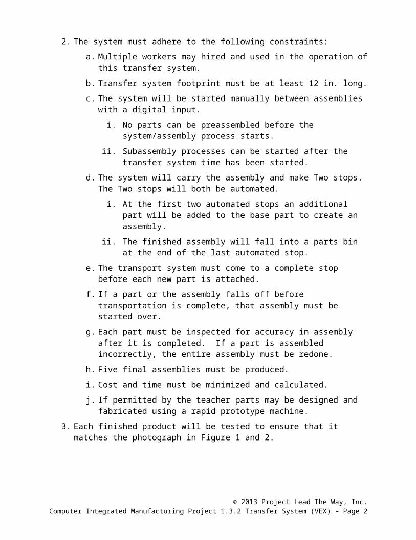
3. Each finished product will be tested to ensure that it matches the photograph in Figure 1 and 2.
Figure 1 Figure 2 Figure 3
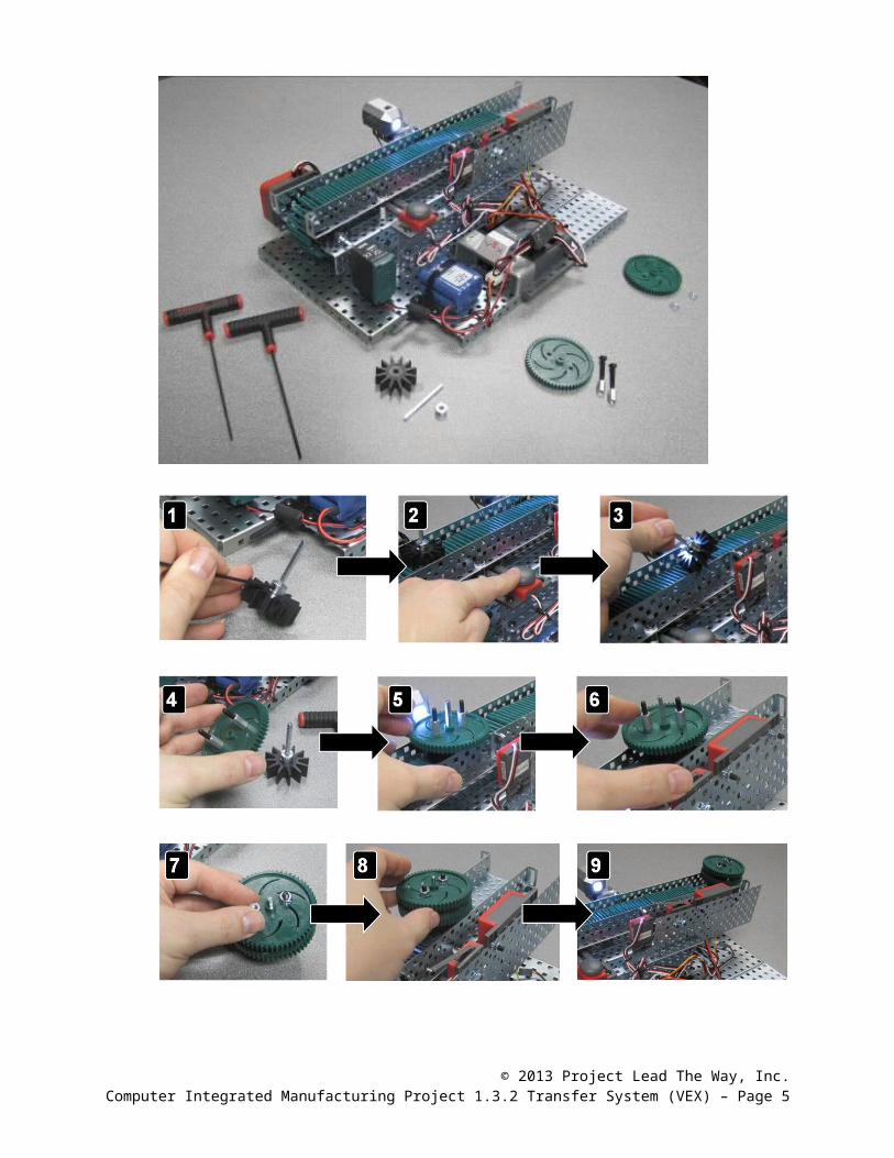
4. Assembly process steps, parts, and subassemblies.
Parts used to create one assembly
1x Intake Roller2x 60-Tooth Gear1x Shaft Colar1x 2 in. Drive Shaft2x ½ in.Standoff2x Screw – 8/32 in.x1 in.2x 8-32 Kep Nuts
© 2013 Project Lead The Way, Inc.Computer Integrated Manufacturing Project 1.3.2 Transfer System (VEX) – Page 2
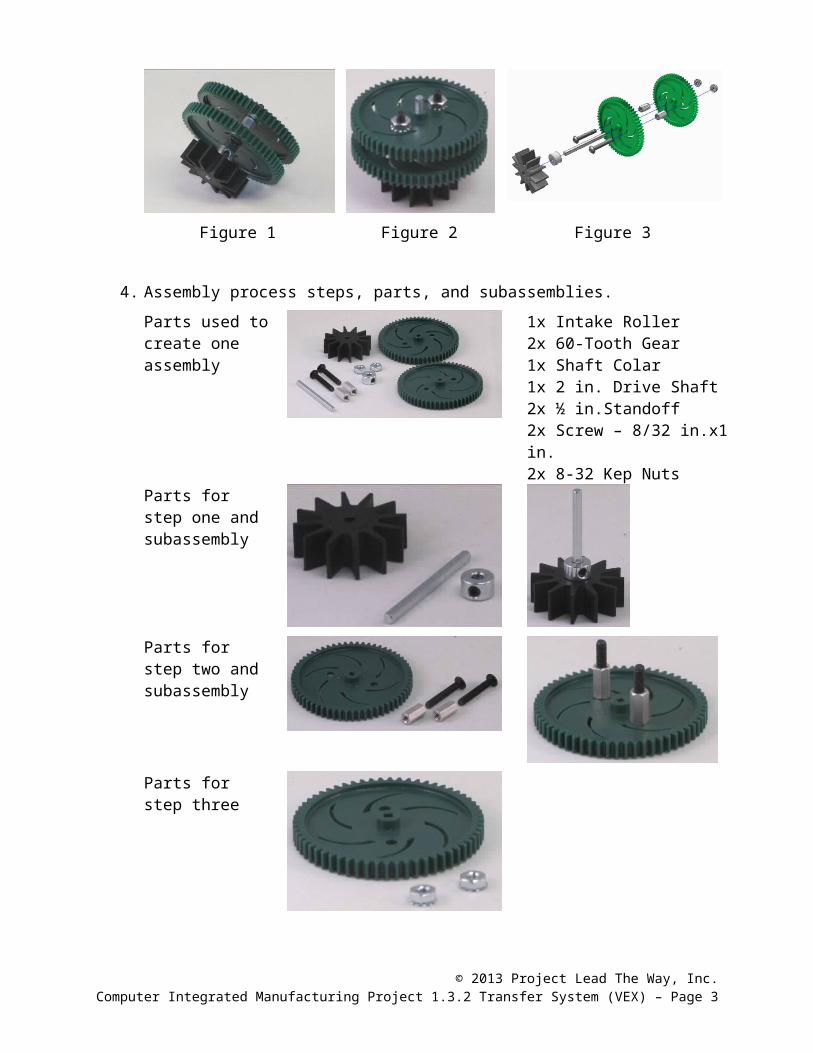
Parts for step one and subassembly
Parts for step two and subassembly
Parts for step three
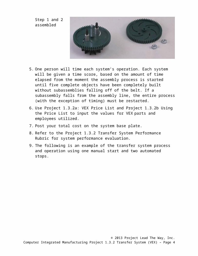
Step 1 and 2 assembled
5. One person will time each system’s operation. Each system will be given a time score, based on the amount of time elapsed from the moment the assembly process is started until five complete objects have been completely built without subassemblies falling off of the belt. If a subassembly falls from the assembly line, the entire process (with the exception of timing) must be restarted.
6. Use Project 1.3.2a: VEX Price List and Project 1.3.2b Using the Price List to input the values for VEX parts and employees utilized.
7. Post your total cost on the system base plate.
8. Refer to the Project 1.3.2 Transfer System Performance Rubric for system performance evaluation.
9. The following is an example of the transfer system process and operation using one manual start and two automated stops.
© 2013 Project Lead The Way, Inc.Computer Integrated Manufacturing Project 1.3.2 Transfer System (VEX) – Page 3
© 2013 Project Lead The Way, Inc.Computer Integrated Manufacturing Project 1.3.2 Transfer System (VEX) – Page 4
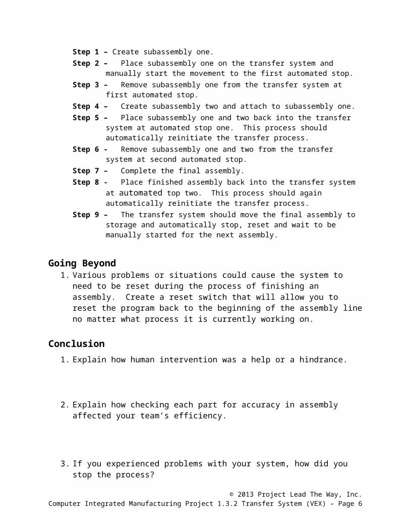
Step 1 – Create subassembly one.Step 2 – Place subassembly one on the transfer system and manually start the
movement to the first automated stop.Step 3 – Remove subassembly one from the transfer system at first automated stop.Step 4 – Create subassembly two and attach to subassembly one.Step 5 – Place subassembly one and two back into the transfer system at automated
stop one. This process should automatically reinitiate the transfer process.Step 6 - Remove subassembly one and two from the transfer system at second
automated stop.Step 7 – Complete the final assembly.Step 8 - Place finished assembly back into the transfer system at automated top two.
This process should again automatically reinitiate the transfer process.Step 9 – The transfer system should move the final assembly to storage and
automatically stop, reset and wait to be manually started for the next assembly.
Going Beyond1. Various problems or situations could cause the system to need to be reset during
the process of finishing an assembly. Create a reset switch that will allow you to reset the program back to the beginning of the assembly line no matter what process it is currently working on.
Conclusion1. Explain how human intervention was a help or a hindrance.
2. Explain how checking each part for accuracy in assembly affected your team’s efficiency.
3. If you experienced problems with your system, how did you stop the process?
4. What constraints affected the cost of your system? If you could modify these system constraints (other than length and output), what changes would you make?
5. Explain the importance of determining the amount of time taken to complete the operation sequence and the cost of parts.
© 2013 Project Lead The Way, Inc.Computer Integrated Manufacturing Project 1.3.2 Transfer System (VEX) – Page 5
6. Explain why your team’s transfer system performed better than other teams’ systems.
© 2013 Project Lead The Way, Inc.Computer Integrated Manufacturing Project 1.3.2 Transfer System (VEX) – Page 6