Progressive Waves - sciencedoctorschool.files.wordpress.com€¦ · Web view03/05/2020 ·...
82
Name ______________________________ Wave s
Transcript of Progressive Waves - sciencedoctorschool.files.wordpress.com€¦ · Web view03/05/2020 ·...
Name ______________________________
Teacher ______________________________
Waves
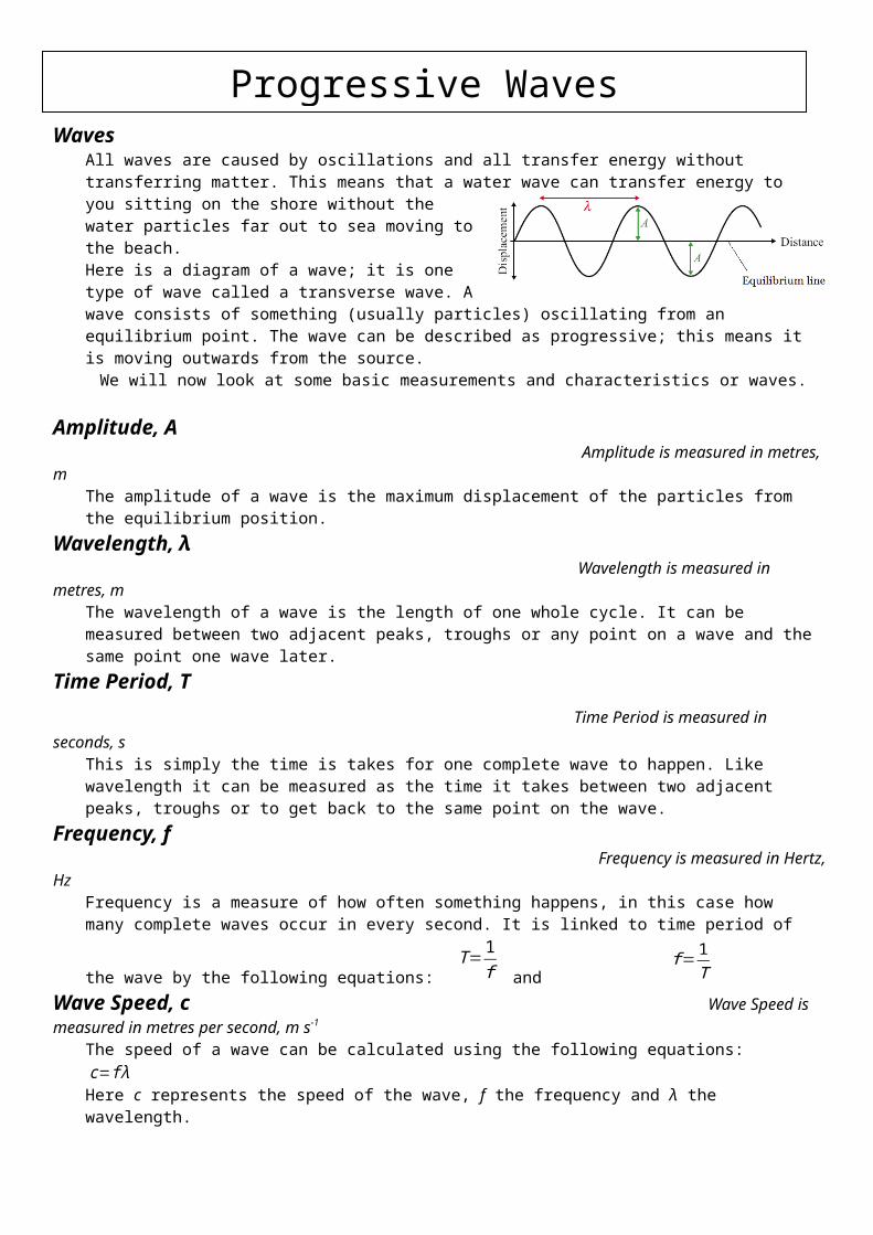
WavesAll waves are caused by oscillations and all transfer energy without transferring matter. This means that a water wave can transfer energy to you sitting on the shore without the water particles far out to sea moving to the beach. Here is a diagram of a wave; it is one type of wave called a transverse wave. A wave consists of something (usually particles) oscillating from an equilibrium point. The wave can be described as progressive; this means it is moving outwards from the source.
We will now look at some basic measurements and characteristics or waves.
Amplitude, A Amplitude is measured in metres, m
The amplitude of a wave is the maximum displacement of the particles from the equilibrium position.
Wavelength, λ Wavelength is measured in metres, m
The wavelength of a wave is the length of one whole cycle. It can be measured between two adjacent peaks, troughs or any point on a wave and the same point one wave later.
Time Period, T Time Period is measured in seconds, s
This is simply the time is takes for one complete wave to happen. Like wavelength it can be measured as the time it takes between two adjacent peaks, troughs or to get back to the same point on the wave.
Frequency, f Frequency is measured in Hertz, Hz
Frequency is a measure of how often something happens, in this case how many complete waves occur in every second. It is linked to time period of the wave by the
following equations: T=1
f and f= 1
TWave Speed, c Wave Speed is measured in metres per second, m s-1
The speed of a wave can be calculated using the following equations: c=fλHere c represents the speed of the wave, f the frequency and λ the wavelength.
Phase Difference Phase Difference is measured in radians, rad
If we look at two particles a wavelength apart (such as C and G) we would see that they are oscillating in time with each other. We say that they are completely in phase. Two points half a wavelength apart (such as I and K) we would see that they are always moving in opposite directions. We say that they are completely out of phase.The phase difference between two points depends on what fraction of a wavelength lies between them
B C D E F G H I J K L MPhase Difference from A (radians) ½π 1π 1½π 2π 2½π 3π 3½π 4π 4½π 5π 5½π 6π
Progressive Waves
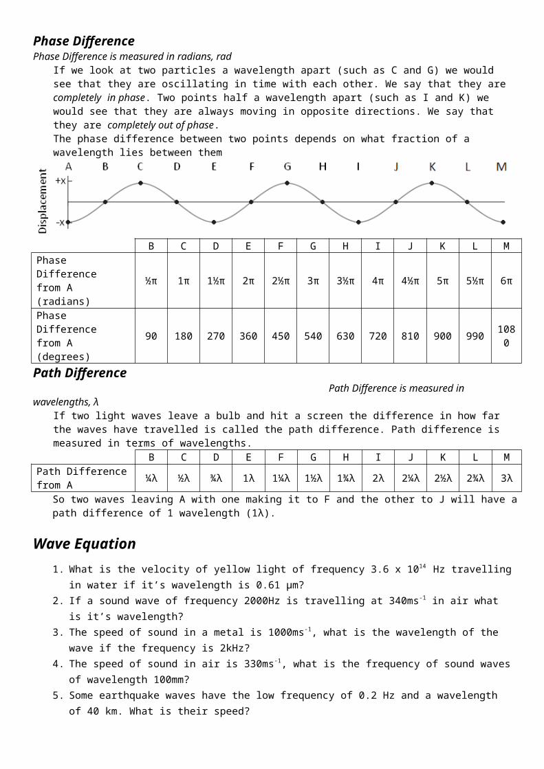
Phase Difference from A (degrees) 90 180 270 360 450 540 630 720 810 900 990 108
0Path Difference Path Difference is measured in wavelengths, λ
If two light waves leave a bulb and hit a screen the difference in how far the waves have travelled is called the path difference. Path difference is measured in terms of wavelengths.
B C D E F G H I J K L MPath Difference from A ¼λ ½λ ¾λ 1λ 1¼λ 1½λ 1¾λ 2λ 2¼λ 2½λ 2¾λ 3λ
So two waves leaving A with one making it to F and the other to J will have a path difference of 1 wavelength (1λ).
Wave Equation1. What is the velocity of yellow light of frequency 3.6 x 10¹⁴ Hz travelling in water if it’s
wavelength is 0.61 µm?2. If a sound wave of frequency 2000Hz is travelling at 340ms-1 in air what is it’s
wavelength?3. The speed of sound in a metal is 1000ms-1, what is the wavelength of the wave if the
frequency is 2kHz?4. The speed of sound in air is 330ms-1, what is the frequency of sound waves of
wavelength 100mm?5. Some earthquake waves have the low frequency of 0.2 Hz and a wavelength of 40 km.
What is their speed? 6. Electromagnetic waves travel at 3 x 10 8 ms-1, what is the frequency of a wave if its
wavelength is 100m?7. A radio wave of frequency 198 kHz. What is the wavelength of the waves that arrive at
your radio?8. What is the frequency of sound waves travelling in air at 340ms-1 if their wavelength is
0.21m?9. What is the speed of sound waves in water that travel at a frequency of 35kHz with a
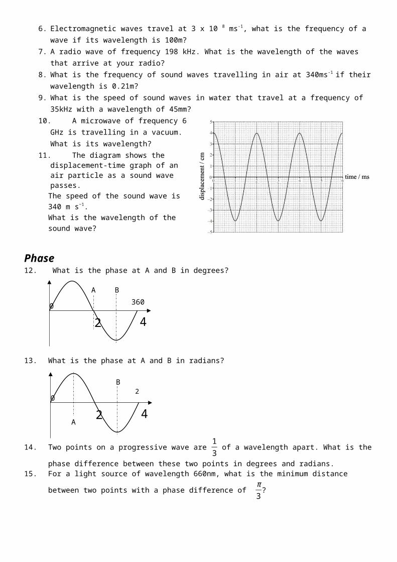
wavelength of 45mm?10.A microwave of frequency 6 GHz is
travelling in a vacuum. What is its wavelength?
11.The diagram shows the displacement-time graph of an air particle as a sound wave passes.The speed of the sound wave is 340 m s−1.What is the wavelength of the sound wave?
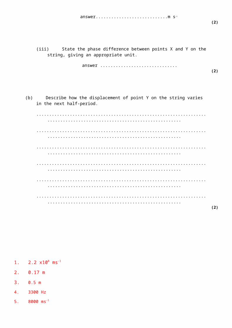
Phase12. What is the phase at A and B in degrees?
A B
3600
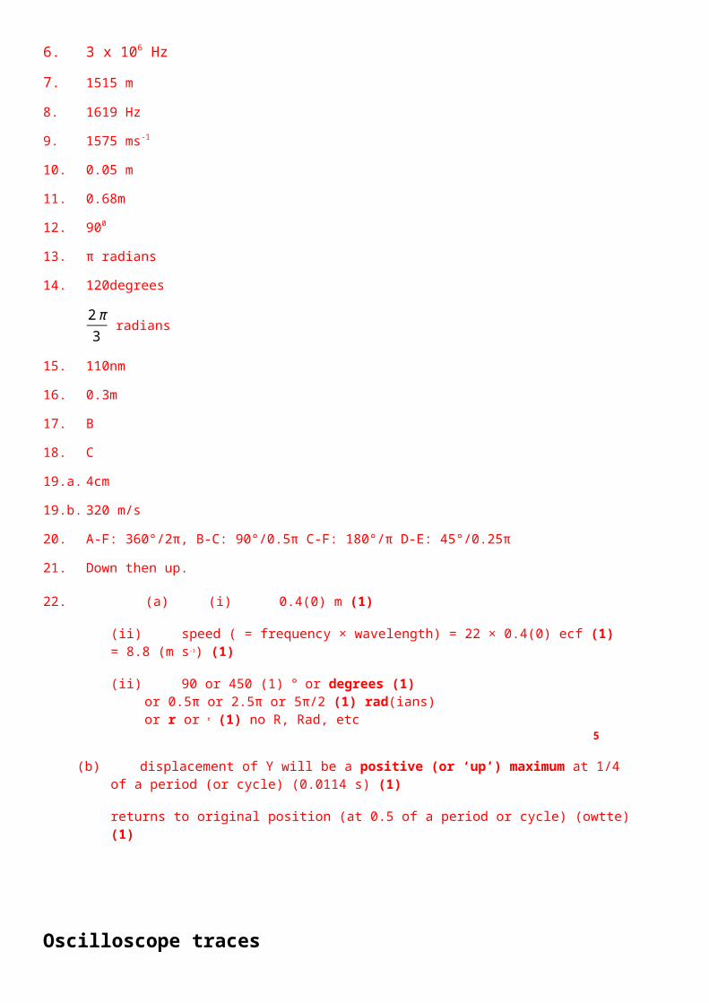
13. What is the phase at A and B in radians?
14. Two points on a progressive wave are 13 of a wavelength apart. What is the phase
difference between these two points in degrees and radians.15. For a light source of wavelength 660nm, what is the minimum distance between two
points with a phase difference of π3 ?
16. The speed of sound in steel is 6000ms-1. For a sound wave of frequency 2500Hz, what is the minimum distance between two points with a phase difference of π
4 ?17. The speed of sound in water is 1500 m s−1. For a sound wave in water having
frequency 2500 Hz, what is the minimum distance between two points at which the vibrations are π
3 rad out of phase?
A 0.05 m
B 0.10 m
C 0.15 m
D 0.20 m
18. The least distance between two points of a progressive transverse wave which have a phase difference of π
3 rad is 0.050 m. If the frequency of the wave is 500 Hz, what is the speed of the wave?
A 25 m s–1
B 75 m s–1
C 150 m s–1
D 1666 m s–1
Wave Graphs/Diagrams19. Look at the two graphs in, which refer to the same wave.a) State the amplitude of the
wave. (1 mark)b) Calculate the speed of the wave. (3 marks)
A
B
20

20. The graph shows a transverse wave.
Figure 5State the phase difference between the following points on the wave in degrees and radians. A and F B and C C and F D and E
21. In the diagram below there is a knot at point P of the rope, which is showing a transverse progressive wave travelling from left to right.
Describe what will happen to the vertical displacement of the knot in the next complete cycle.
22. (a) The diagram below represents a progressive wave travelling from left to right on a stretched string.
(i) Calculate the wavelength of the wave.
answer ................................... m(1)
(ii) The frequency of the wave is 22 Hz. Calculate the speed of the wave.
answer............................m s–1
(2)

(iii) State the phase difference between points X and Y on the string, giving an appropriate unit.
answer ..............................(2)
(b) Describe how the displacement of point Y on the string varies in the next half-period.
......................................................................................................................
......................................................................................................................
......................................................................................................................
......................................................................................................................
......................................................................................................................
......................................................................................................................(2)
1. 2.2 x10⁸ ms-1
2. 0.17 m
3. 0.5 m
4. 3300 Hz
5. 8000 ms-1
6. 3 x 10⁶ Hz
7. 1515 m
8. 1619 Hz
9. 1575 ms-1
10. 0.05 m
11. 0.68m
12. 900
13. π radians
14. 120degrees
2 π3 radians
15. 110nm
16. 0.3m
17. B
18. C
19.a. 4cm
19.b. 320 m/s
20. A-F: 360°/2π, B-C: 90°/0.5π C-F: 180°/π D-E: 45°/0.25π
21. Down then up.
22. (a) (i) 0.4(0) m (1)
(ii) speed ( = frequency × wavelength) = 22 × 0.4(0) ecf (1)= 8.8 (m s–1) (1)
(ii) 90 or 450 (1) ° or degrees (1)or 0.5π or 2.5π or 5π/2 (1) rad(ians)or r or r (1) no R, Rad, etc
5
(b) displacement of Y will be a positive (or ‘up’) maximum at 1/4 of a period (or cycle) (0.0114 s) (1)
returns to original position (at 0.5 of a period or cycle) (owtte) (1)
Oscilloscope traces1 Calculate the frequency of the wave in the diagram if the time base is set
to:A 5.0 ms cm–1 (2 marks)B 2.0 s cm–1 (2 marks)C 100 ns cm–1 (2 marks)
Each square represents 1 cm.
2. An electromagnetic wave is picked up by a detector, which produces an electrical signal. This signal is amplified and displayed on an oscilloscope screen. Each square represents 1 cm.
a The scale on the y-axis is 2.0 V cm–1. Determine the amplitude of the electrical signal.
b The time base is set to 25 ns cm–1. Determine the frequency of the signal and hence the wavelength of the electromagnetic wave.
c What type of electromagnetic wave is being detected?
3
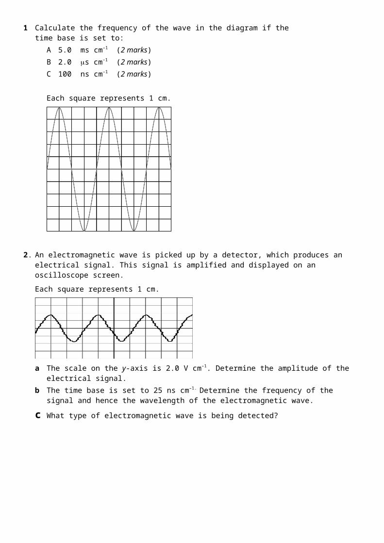
Figure 2Figure 2 shows two waves displayed on an oscilloscope. The oscilloscope is set to 2.0 V div–1 and a time base of 2.0 μs div–1.a What is the amplitude of signal A? (1 mark)
b What is the period of signal A? (1 mark)
c What is the frequency of signal A? (1 mark)
d What is the amplitude of signal B? (1 mark)
e What is the period of signal B? (1 mark)
f What is the frequency of signal B? (1 mark)
4
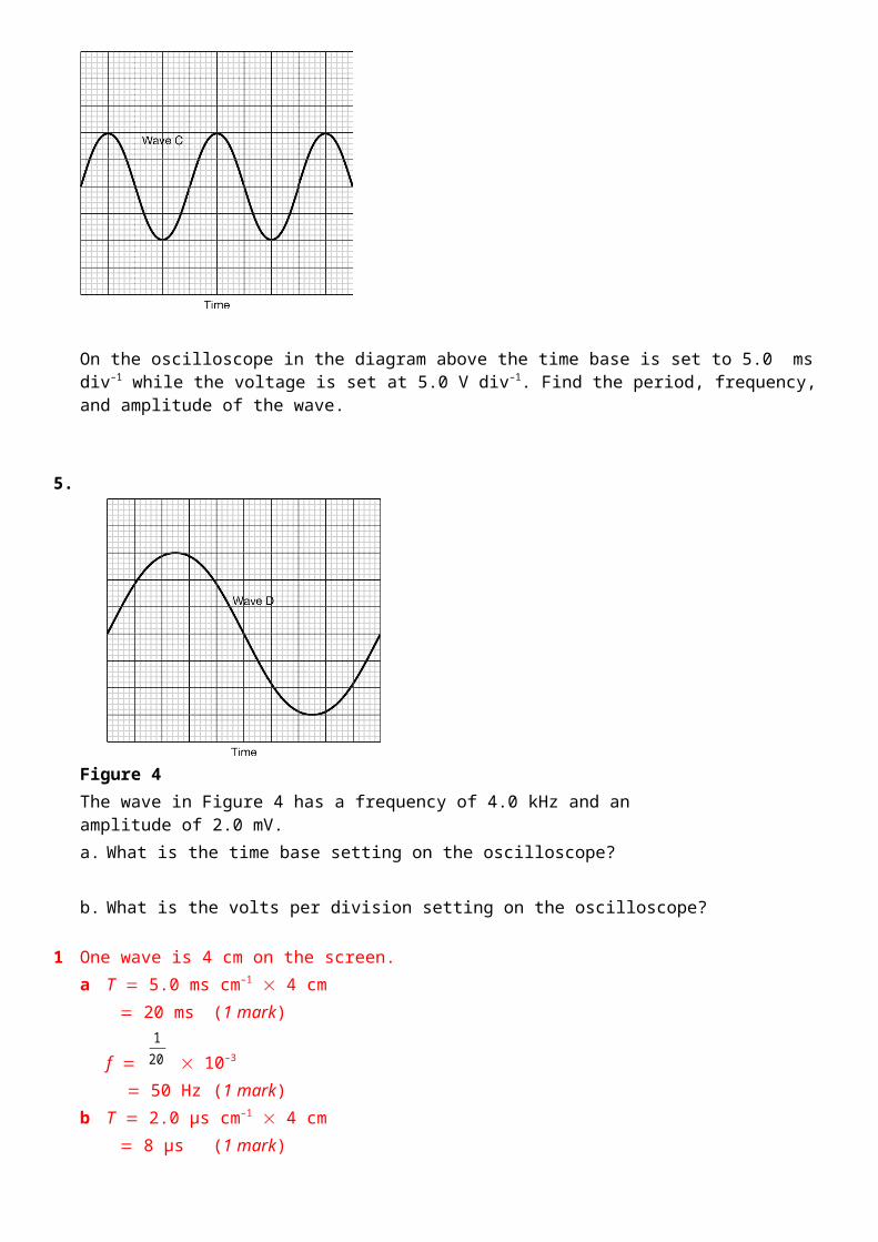
On the oscilloscope in the diagram above the time base is set to 5.0 ms div–1 while the voltage is set at 5.0 V div–1. Find the period, frequency, and amplitude of the wave.
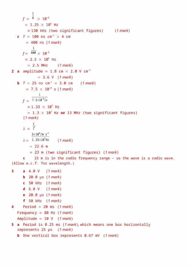
5.
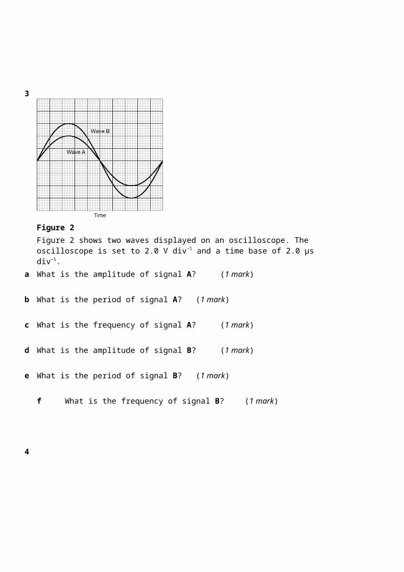
Figure 4The wave in Figure 4 has a frequency of 4.0 kHz and an amplitude of 2.0 mV.a. What is the time base setting on the oscilloscope?
b. What is the volts per division setting on the oscilloscope?
1 One wave is 4 cm on the screen.a T 5.0 ms cm–1 4 cm
20 ms (1 mark)
f 1
20 10–3
50 Hz (1 mark)b T 2.0 μs cm–1 4 cm
8 μs (1 mark)
f 18 10–6
1.25 105 Hz 130 kHz (two significant figures) (1 mark)
c T 100 ns cm–1 4 cm 400 ns (1 mark)
f 1
400 10–9
2.5 106 Hz 2.5 MHz (1 mark)
2 a amplitude 1.8 cm 2.0 V cm–1
3.6 V (1 mark)b T 25 ns cm–1 3.0 cm (1 mark)
7.5 10–8 s (1 mark)
f
17 .5×10–8 s
1.33 107 Hz 1.3 107 Hz or 13 MHz (two significant figures) (1 mark)
3×10⁸ m s–1
1 .33×107 Hz (1 mark) 22.6 m 23 m (two significant figures) (1 mark)c 23 m is in the radio frequency range – so the wave is a radio wave.
(Allow e.c.f. for wavelength.)
3 a 4.0 V (1 mark)b 20.0 μs (1 mark)c 50 kHz (1 mark)d 6.0 V (1 mark)e 20.0 μs (1 mark)f 50 kHz (1 mark)
4 Period 20 ms (1 mark)Frequency 80 Hz (1 mark)Amplitude 10 V (1 mark)
5 a Period is 0.25 ms (1 mark), which means one box horizontally represents 25 μs (1 mark)
b One vertical box represents 0.67 mV (1 mark)
WavesAll waves are caused by oscillations and all transfer energy without transferring matter. This means that a sound wave can transfer energy to your eardrum from a far speaker without the air particles by the speaker moving into your ear. We will now look at the two types of waves and how they are different
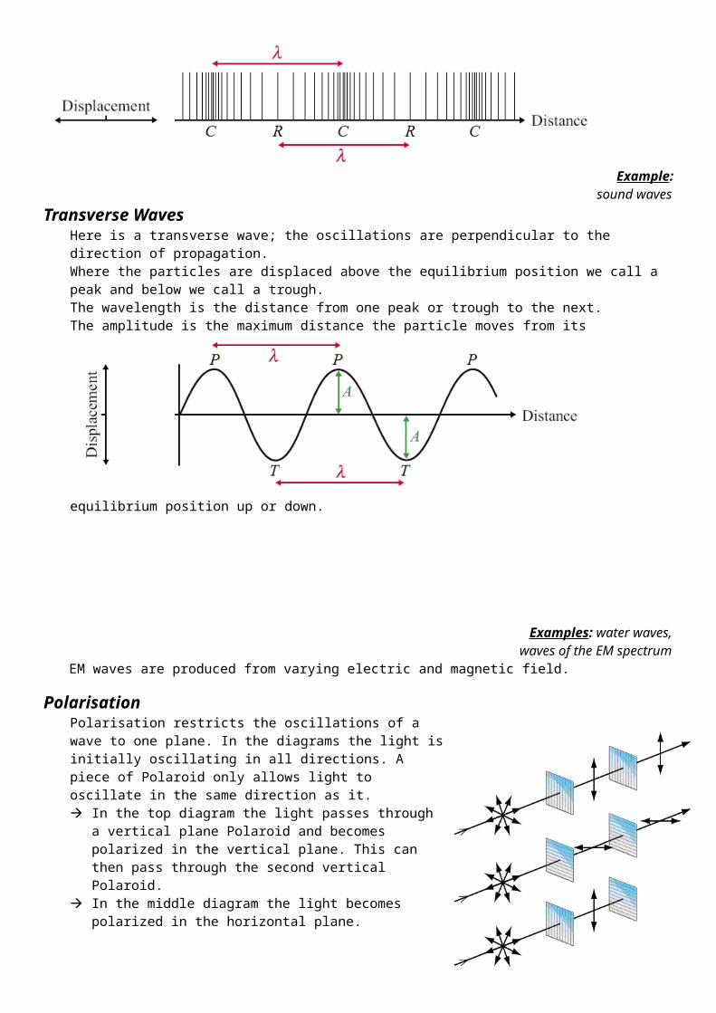
Longitudinal WavesHere is a longitudinal wave; the oscillations are parallel to the direction of propagation (travel).Where the particles are close together we call a compression and where they are spread we call a rarefaction. The wavelength is the distance from one compression or rarefaction to the next.The amplitude is the maximum distance the particle moves from its equilibrium position to the right of left.
Example: sound waves
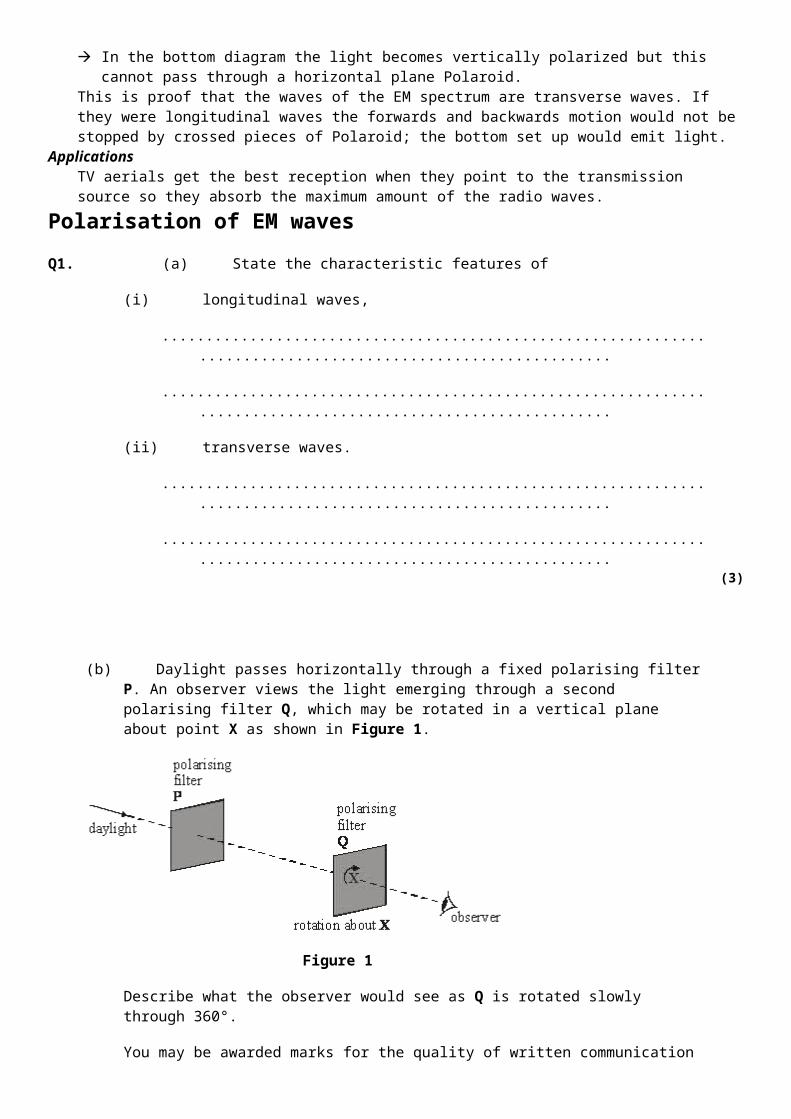
Transverse WavesHere is a transverse wave; the oscillations are perpendicular to the direction of propagation.Where the particles are displaced above the equilibrium position we call a peak and below we call a trough.The wavelength is the distance from one peak or trough to the next.The amplitude is the maximum distance the particle moves from its equilibrium position
up or down.
Examples: water waves,waves of the EM spectrum
EM waves are produced from varying electric and magnetic field.
PolarisationPolarisation restricts the oscillations of a wave to one plane. In the diagrams the light is initially oscillating in all directions. A piece of Polaroid only allows light to oscillate in the same direction as it. In the top diagram the light passes through a
vertical plane Polaroid and becomes polarized in the vertical plane. This can then pass through the second vertical Polaroid.
Longitudinal and transverse waves
In the middle diagram the light becomes polarized in the horizontal plane. In the bottom diagram the light becomes vertically polarized but this cannot pass
through a horizontal plane Polaroid.This is proof that the waves of the EM spectrum are transverse waves. If they were longitudinal waves the forwards and backwards motion would not be stopped by crossed pieces of Polaroid; the bottom set up would emit light.
ApplicationsTV aerials get the best reception when they point to the transmission source so they absorb the maximum amount of the radio waves.
Polarisation of EM wavesQ1. (a) State the characteristic features of
(i) longitudinal waves,
.............................................................................................................
.............................................................................................................
(ii) transverse waves.
.............................................................................................................
.............................................................................................................(3)
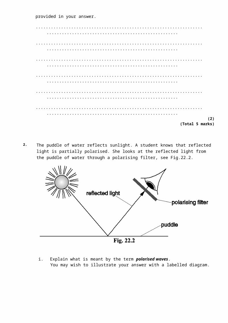
(b) Daylight passes horizontally through a fixed polarising filter P. An observer views the light emerging through a second polarising filter Q, which may be rotated in a vertical plane about point X as shown in Figure 1.
Figure 1
Describe what the observer would see as Q is rotated slowly through 360°.
You may be awarded marks for the quality of written communication provided in your answer.
......................................................................................................................
......................................................................................................................
......................................................................................................................
......................................................................................................................
......................................................................................................................
......................................................................................................................(2)
(Total 5 marks)
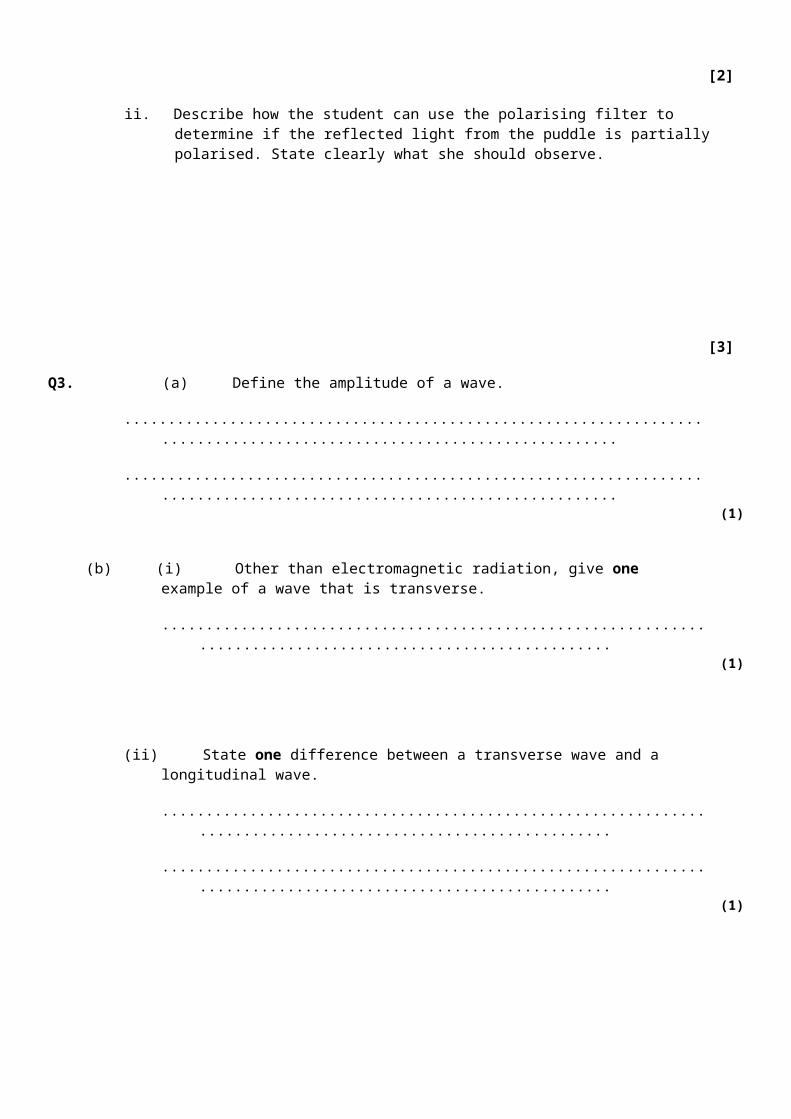
2. The puddle of water reflects sunlight. A student knows that reflected light is partially polarised. She looks at the reflected light from the puddle of water through a polarising filter, see Fig.22.2.
i. Explain what is meant by the term polarised waves.You may wish to illustrate your answer with a labelled diagram.
[2]
ii. Describe how the student can use the polarising filter to determine if the reflected light from the puddle is partially polarised. State clearly what she should observe.
[3]
Q3. (a) Define the amplitude of a wave.
......................................................................................................................
......................................................................................................................(1)
(b) (i) Other than electromagnetic radiation, give one example of a wave that is transverse.
.............................................................................................................(1)
(ii) State one difference between a transverse wave and a longitudinal wave.
.............................................................................................................
.............................................................................................................(1)
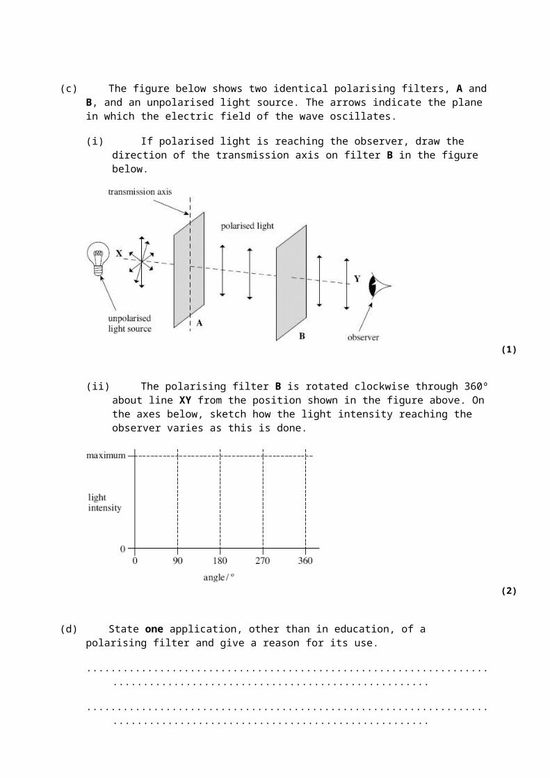
(c) The figure below shows two identical polarising filters, A and B, and an unpolarised light source. The arrows indicate the plane in which the electric field of the wave oscillates.
(i) If polarised light is reaching the observer, draw the direction of the transmission axis on filter B in the figure below.
(1)
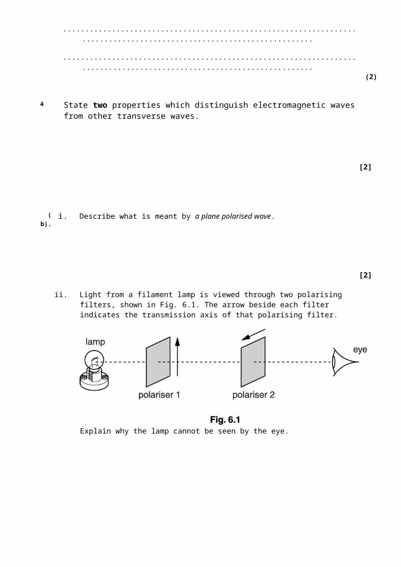
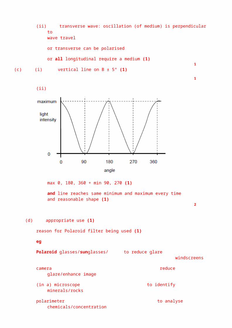
(ii) The polarising filter B is rotated clockwise through 360º about line XY from the position shown in the figure above. On the axes below, sketch how the light intensity reaching the observer varies as this is done.
(2)
(d) State one application, other than in education, of a polarising filter and give a reason for its use.
......................................................................................................................
......................................................................................................................
......................................................................................................................
......................................................................................................................(2)
4 State two properties which distinguish electromagnetic waves from other transverse waves.
[2]
(b).
i. Describe what is meant by a plane polarised wave.
[2]
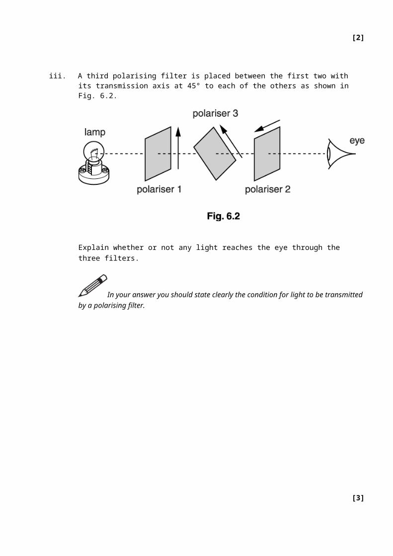
ii. Light from a filament lamp is viewed through two polarising filters, shown in Fig. 6.1. The arrow beside each filter indicates the transmission axis of that polarising filter.
Explain why the lamp cannot be seen by the eye.
[2]
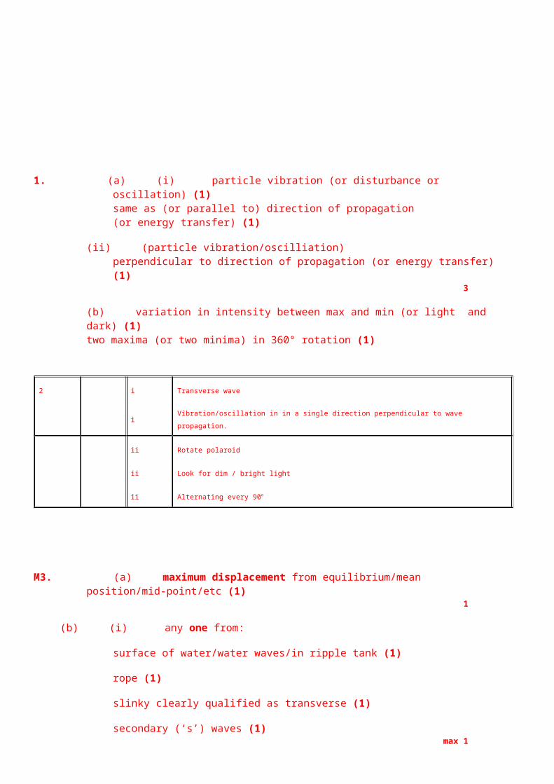
iii. A third polarising filter is placed between the first two with its transmission axis at 45° to each of the others as shown in Fig. 6.2.
Explain whether or not any light reaches the eye through the three filters.
In your answer you should state clearly the condition for light to be transmitted by a polarising filter.
[3]
1. (a) (i) particle vibration (or disturbance or oscillation) (1)same as (or parallel to) direction of propagation(or energy transfer) (1)
(ii) (particle vibration/oscilliation)perpendicular to direction of propagation (or energy transfer) (1)
3
(b) variation in intensity between max and min (or light and dark) (1)two maxima (or two minima) in 360° rotation (1)
2 i Transverse wave
i Vibration/oscillation in in a single direction perpendicular to wave propagation.
ii Rotate polaroid
ii Look for dim / bright light
ii Alternating every 90o
M3. (a) maximum displacement from equilibrium/meanposition/mid-point/etc (1)
1
(b) (i) any one from:
surface of water/water waves/in ripple tank (1)
rope (1)
slinky clearly qualified as transverse (1)
secondary (‘s’) waves (1)max 1
(ii) transverse wave: oscillation (of medium) is perpendicular towave travel
or transverse can be polarised
or all longitudinal require a medium (1)1
(c) (i) vertical line on B ± 5° (1)
1
(ii)
max 0, 180, 360 + min 90, 270 (1)
and line reaches same minimum and maximum every timeand reasonable shape (1)
2
(d) appropriate use (1)
reason for Polaroid filter being used (1)
eg
Polaroid glasses/sunglasses/ to reduce glare windscreens
camera reduce glare/enhance image
(in a) microscope to identify minerals/rocks
polarimeter to analyse chemicals/concentration or type of sugar
stress analysis reveals areas of high/low stress/ other relevant detail
LCD displays very low power/other relevant detail
3D glasses enhance viewing experience, etc2
4 a all travel at speed of light B1 max 2 marks from 3 marking points
through a vacuum
are oscillating E and B fields or are caused by accelerating
charges / AW
B1
if 3 properties are given withhold one mark for each
incorrect property so 2 correct and 1 incorrect would score
1 mark; 1 correct and 2 incorrect would score zero, etc
Examiner's Comments
This was well answered with almost all knowing the
properties of electromagnetic waves which distinguish
them from other waves.
b ioscillations (of particles / e-m fields along the wave) are in
one direction onlyB1
iperpendicular to the direction of wave propagation / of
travel of the wave / of energy transferB1
iilight passing through polariser 1 is vertically polarised /
only vertical oscillations of the light exist beyond the
polariser 1/AW
B1allow any words indicating vertical, e.g. up and down; for horizontal, e.g. at 90o to vertical or crossed polarisers
iionly (the component of) light in the horizontal plane can
pass through polariser 2 so no light reaches the eyeB1
accept using Malus’ law Itrans = Iincidentcos2θ with θ = 90o gives Itrans = 0
iiiafter polariser 1 the component of the vertically polarised
light at 45° passes through polariser 3B1
QWC statement to the effect that component of light along polarising axis of filter is transmitted
iiithe polarised light beyond polariser 3 has a component at
45° which passes through polariser 2 so light reaches the
eye
B1B1
accept using Malus’ law Itrans = Iincidentcos2θ with θ = 45o gives Itrans = Iincident/2same process gives Itrans = Iincident/2 again
iii
or mark a typical answer of the form (max 2) as follows some of the vertically polarised light passes through polariser 3 and some of this passes through polariser 2 because in each case the polarised light is not at right angles to the transmission axis of the polariser
so ¼ of light after polariser 1 reaches eye (assuming no
absorption)
accept answers in terms of amplitudes rather than
intensities, i.e. A = A0 cos θ, etc.
iii Examiner's Comments
Most candidates just repeated the question when explaining plane polarisation, failing to define clearly the plane or direction of oscillation. Candidates should be encouraged to think of a polarised wave as oscillating in a certain direction rather than in a single plane,
and to think of the vector nature of the oscillation and answer in terms of components. Those who had some understanding of Malus' law scored good marks. Those without a mathematical approach who considered that a polarising filter only stopped completely oscillations perpendicular to the transmission axis also often gave good answers. The majority considered that once polarised only oscillations in the direction of the first polariser's transmission axis could exist and would be maintained through any subsequent polarisers. They therefore came to the wrong conclusions.
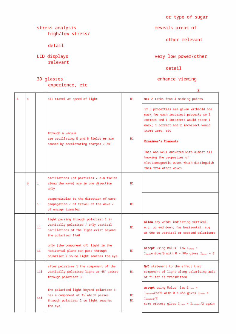
SuperpositionHere are two waves that have amplitudes of 1.0 travelling in opposite directions:
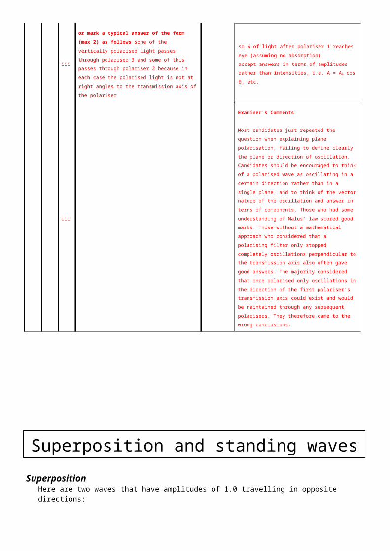
Superposition is the process by which two waves combine into a single wave form when they overlap.
If we add these waves together the resultant depends on where the peaks of the waves are compared to each other. Here are three examples of what the resultant could be: a wave with an amplitude of 1.5, no resultant wave at all and a wave with an amplitude of 2.0
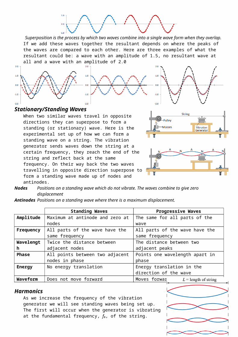
Stationary/Standing WavesWhen two similar waves travel in opposite directions they can superpose to form a standing (or stationary) wave. Here is the experimental set up of how we can form a standing wave on a string. The vibration generator sends waves down the string at a certain frequency, they reach the end of the string and reflect back at the same frequency. On their way back the two waves travelling in opposite direction superpose to form a standing wave made up of nodes and antinodes.
Superposition and standing waves
Nodes Positions on a standing wave which do not vibrate. The waves combine to give zero displacement
Antinodes Positions on a standing wave where there is a maximum displacement.
Standing Waves Progressive WavesAmplitude Maximum at antinode and zero at
nodesThe same for all parts of the wave
Frequency All parts of the wave have the same frequency
All parts of the wave have the same frequency
Wavelength
Twice the distance between adjacent nodes
The distance between two adjacent peaks
Phase All points between two adjacent nodes in phase
Points one wavelength apart in phase
Energy No energy translation Energy translation in the direction of the wave
Waveform Does not move forward Moves forwards
HarmonicsAs we increase the frequency of the vibration generator we will see standing waves being set up. The first will occur when the generator is vibrating at the fundamental frequency, f0, of the string.
First Harmonic f = f0 λ = 2 L2 nodes and 1 antinode
Second Harmonic f = 2f0 λ = L3 nodes and 2 antinodes
Third Harmonic f = 3f0 λ = ⅔ L4 nodes and 3 antinodes
Forth Harmonic f = 4f0 λ = ½ L5 nodes and 4 antinodes
Superposition
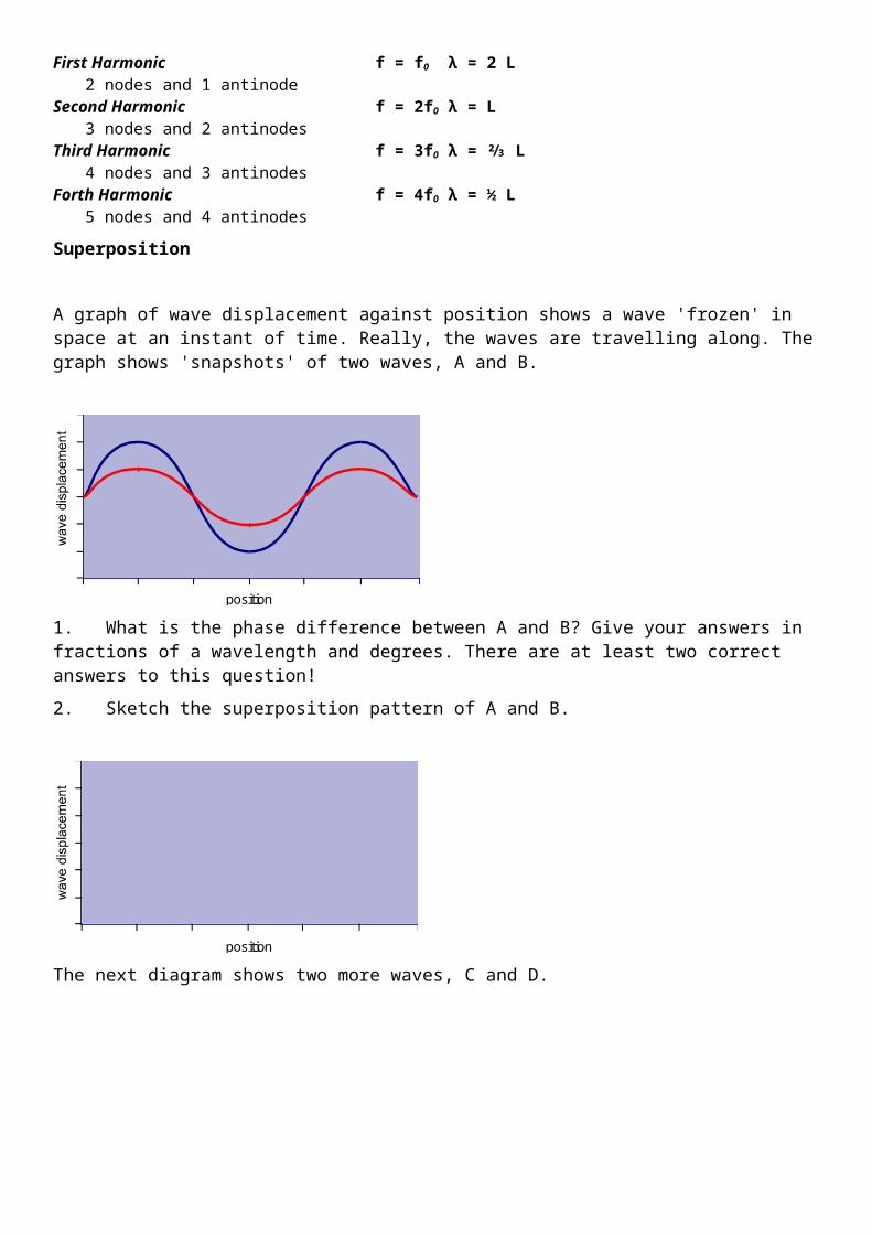
A graph of wave displacement against position shows a wave 'frozen' in space at an instant of time. Really, the waves are travelling along. The graph shows 'snapshots' of two waves, A and B.
position
1. What is the phase difference between A and B? Give your answers in fractions of a wavelength and degrees. There are at least two correct answers to this question!2. Sketch the superposition pattern of A and B.
position
The next diagram shows two more waves, C and D.
position
3. What is the phase difference between C and D?4. Sketch the superposition pattern of C and D.
position
5. What phase angle corresponds to a phase difference of 1/3 of a wavelength?
6. Sketch a diagram showing two waves of equal amplitude with a phase difference equal to 1/3 of a wavelength.
position
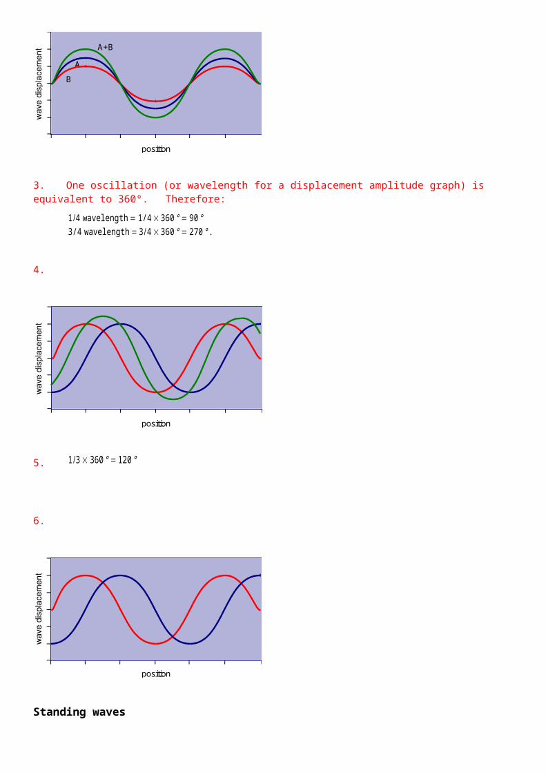
1. Zero phase difference
2.
A
B
A+B
position
3. One oscillation (or wavelength for a displacement amplitude graph) is equivalent to 360º. Therefore:
1/4 wavelength = 1/4 × 360 ° = 90 °3/4 wavelength = 3 /4 × 360 ° = 270 ° .
4.
position
5. 1/3 × 360 ° = 120 °
6.
position
Standing waves
1. How do stationary (standing) waves form? From the superposition of two progressive waves with the same frewuency/wavelength and the same amplitude moving in opposite directions.
2. What are the positions of zero and maximum displacement (amplitude) called? Nodes and antinodes, respectively.
3. What is meant by saying that the sources must be coherent to produce interference effects? The two sources must have the same frequency/wavelength and a fixed or constant phase difference.
4. If two points on a wave have a phase difference of 1080°, are they in phase or out of phase? 1080/360 = 3, and therefore in phase.
5. What is the principle of superposition? When two waves cross, the resultant displacement is the vector sum of their individual displacements.
6. What effect results from the superposition of two waves in phase? Constructive interference.
7. A stationary wave is produced on a stretched wire 0.8 m long that vibrates in its first harmonic mode. What is the wavelength of the stationary wave. 1.6 m
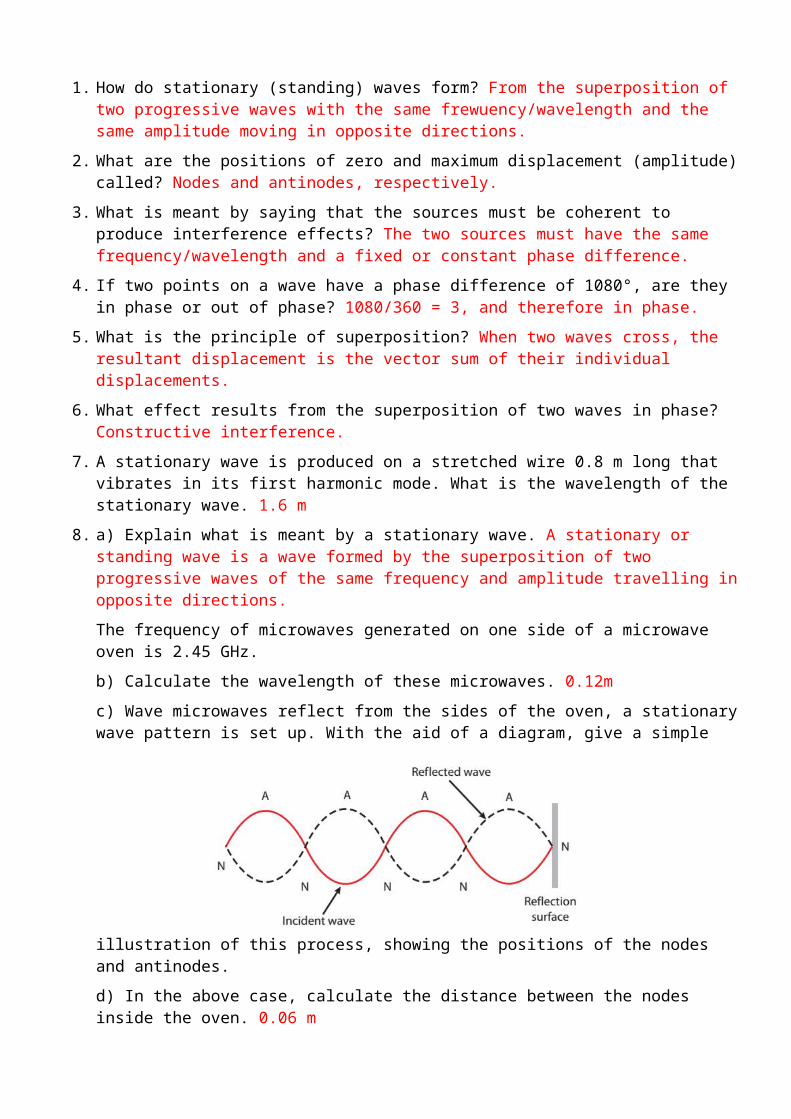
8. a) Explain what is meant by a stationary wave. A stationary or standing wave is a wave formed by the superposition of two progressive waves of the same frequency and amplitude travelling in opposite directions. The frequency of microwaves generated on one side of a microwave oven is 2.45 GHz. b) Calculate the wavelength of these microwaves. 0.12mc) Wave microwaves reflect from the sides of the oven, a stationary wave pattern is set up. With the aid of a diagram, give a simple illustration of this process, showing the positions of the nodes and antinodes.
d) In the above case, calculate the distance between the nodes inside the oven. 0.06 me) If a bar of chocolate is placed in the microwave oven (no turntable used), what effect would be seen after about 30 seconds of irradiation? Holes in the chocolate would appear at the antinode positions & separated by a distance of 0.06 m.
9. A stationary sound wave is generated in a hollow pipe has both ends open (this means that there is an antinode at both ends). The length of the pipe used is 1.2 m and the speed of sound in air is 330 m/s.
a) Draw the two diagrams to illustrate i) first and ii) second harmonic of the modes of vibration in the open pipe; mark on your diagrams the positions of the nodes and antinodes.
b) Calculate the frequency of the first harmonic, the second harmonic and the third harmonic for this open system. 137.5 Hz, 275 Hz, 412.5 Hz
One end of the pipe is now closed. c) Calculate the fundamental frequency and the first harmonic for this closed
system. 69 Hz and 207 Hzd) Comment on the quality of sound resulting from both open and closed pipes.
Closed pipes only give odd harmonics whereas open pipes give all harmonics.
10. The frequency f of waves that travel along a length of string or wire, of length L, under tension T, is given by:
f= 12l √T
μ
where μ is the mass per unit length of the string or wire in kg/m. a) What would happen to the frequency of a wave generated if i) the tension in
the string or wire is doubled or ii) the length of the string is doubled? i) Increases by a factor of √2 ii) decreased by a factor of 2.
The string is stretched between two points 0.65 m apart. b) Calculate the frequency of the fundamental where the tension in the string in
100 N and the mass per unit length is 3.5 kg/m. 4.1 Hzc) What would be the effect on the frequency if a lighter string is used?
Frequency would increase.
Q1.
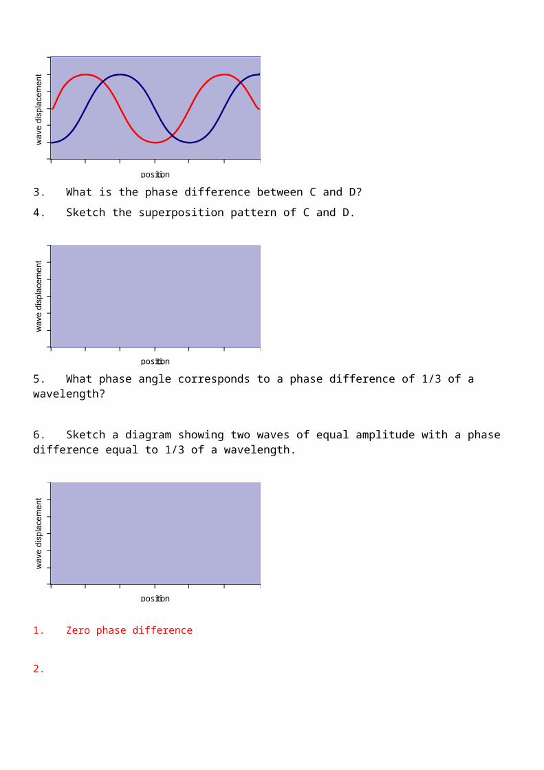
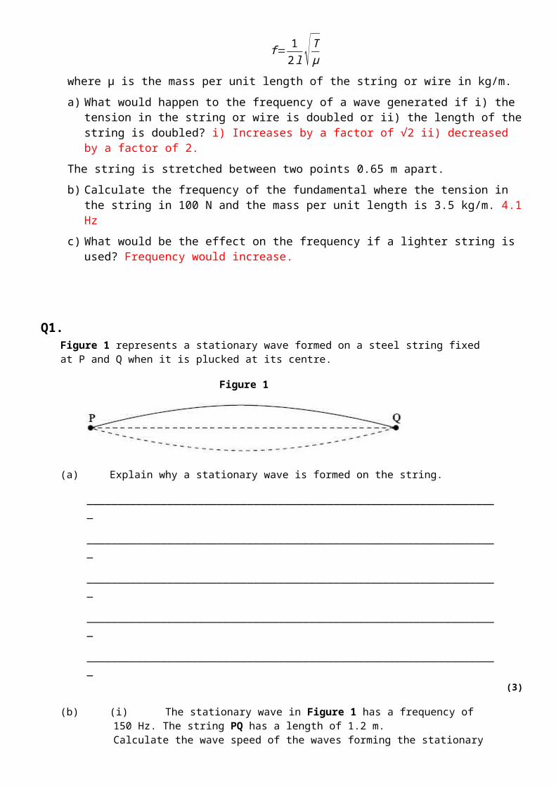
Figure 1 represents a stationary wave formed on a steel string fixed at P and Q when it is plucked at its centre.
Figure 1
(a) Explain why a stationary wave is formed on the string.
___________________________________________________________________
___________________________________________________________________
___________________________________________________________________
___________________________________________________________________
___________________________________________________________________(3)
(b) (i) The stationary wave in Figure 1 has a frequency of 150 Hz. The string PQ has a length of 1.2 m.Calculate the wave speed of the waves forming the stationary wave.
Answer ____________________ m s–1
(2)
(ii) On Figure 2, draw the stationary wave that would be formed on the string at the same tension if it was made to vibrate at a frequency of 450 Hz.
Figure 2
(2)
(Total 7 marks)
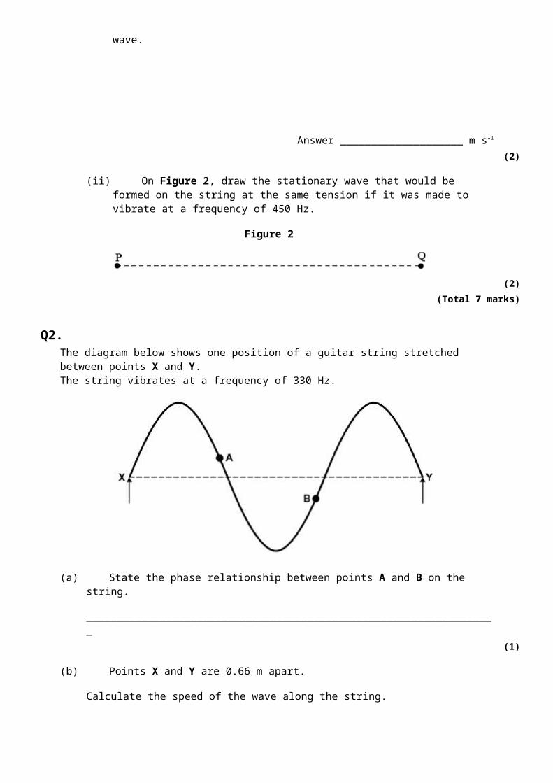
Q2.The diagram below shows one position of a guitar string stretched between points X and Y.The string vibrates at a frequency of 330 Hz.
(a) State the phase relationship between points A and B on the string.
___________________________________________________________________(1)
(b) Points X and Y are 0.66 m apart.
Calculate the speed of the wave along the string.
speed = _________________ m s−1
(2)
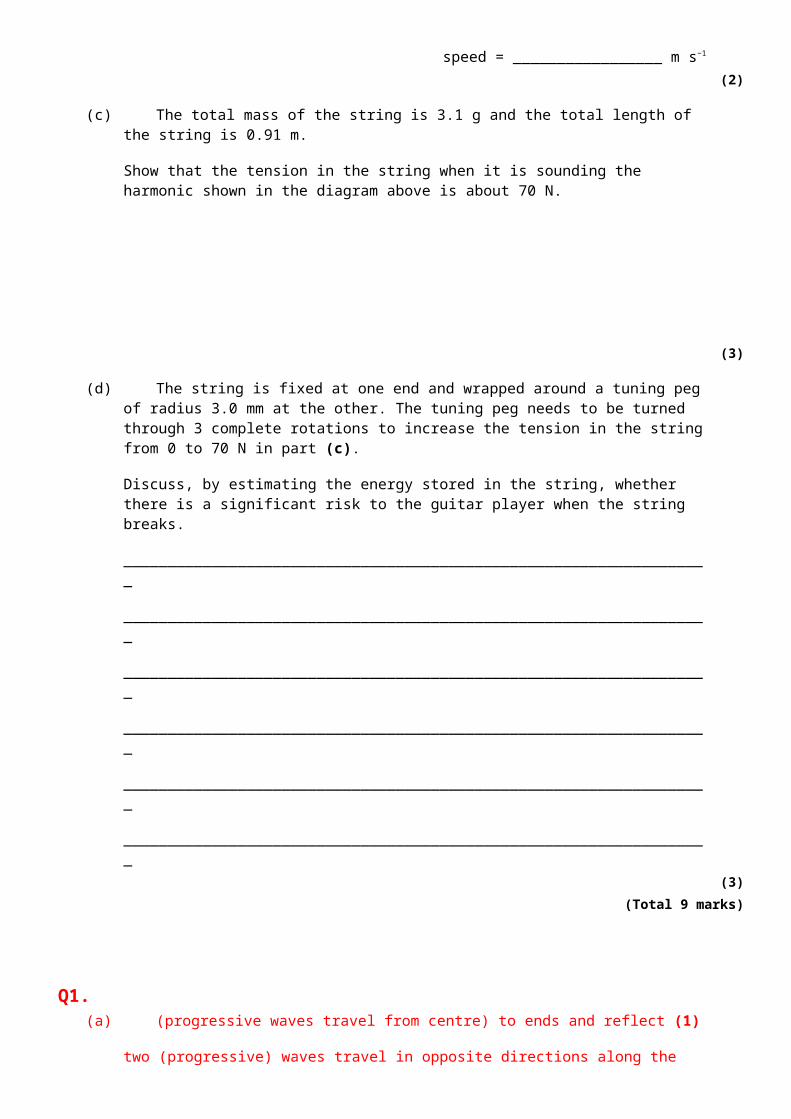
(c) The total mass of the string is 3.1 g and the total length of the string is 0.91 m.
Show that the tension in the string when it is sounding the harmonic shown in the diagram above is about 70 N.
(3)
(d) The string is fixed at one end and wrapped around a tuning peg of radius 3.0 mm at the other. The tuning peg needs to be turned through 3 complete rotations to increase the tension in the string from 0 to 70 N in part (c).
Discuss, by estimating the energy stored in the string, whether there is a significant risk to the guitar player when the string breaks.
___________________________________________________________________
___________________________________________________________________
___________________________________________________________________
___________________________________________________________________
___________________________________________________________________
___________________________________________________________________(3)
(Total 9 marks)
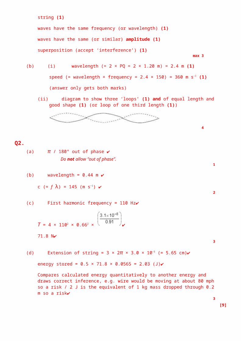
Q1.(a) (progressive waves travel from centre) to ends and reflect (1)
two (progressive) waves travel in opposite directions along the string (1)
waves have the same frequency (or wavelength) (1)
waves have the same (or similar) amplitude (1)
superposition (accept ‘interference’) (1)max 3
(b) (i) wavelength (= 2 × PQ = 2 × 1.20 m) = 2.4 m (1)
speed (= wavelength × frequency = 2.4 × 150) = 360 m s–1 (1)
(answer only gets both marks)
(ii) diagram to show three ‘loops’ (1) and of equal length andgood shape (1) (or loop of one third length (1))
4
Q2.(a) π / 180° out of phase ✔
Do not allow “out of phase”.1
(b) wavelength = 0.44 m ✔
c (= f λ) = 145 (m s−1) ✔2
(c) First harmonic frequency = 110 Hz✔
T = 4 × 1102 × 0.662 × ✔
71.8 N✔3
(d) Extension of string = 3 × 2π × 3.0 × 10−3 (= 5.65 cm)✔

energy stored = 0.5 × 71.8 × 0.0565 = 2.03 (J)✔
Compares calculated energy quantitatively to another energy and draws correct inference, e.g. wire would be moving at about 80 mph so a risk / 2 J is the equivalent of 1 kg mass dropped through 0.2 m so a risk✔
3[9]
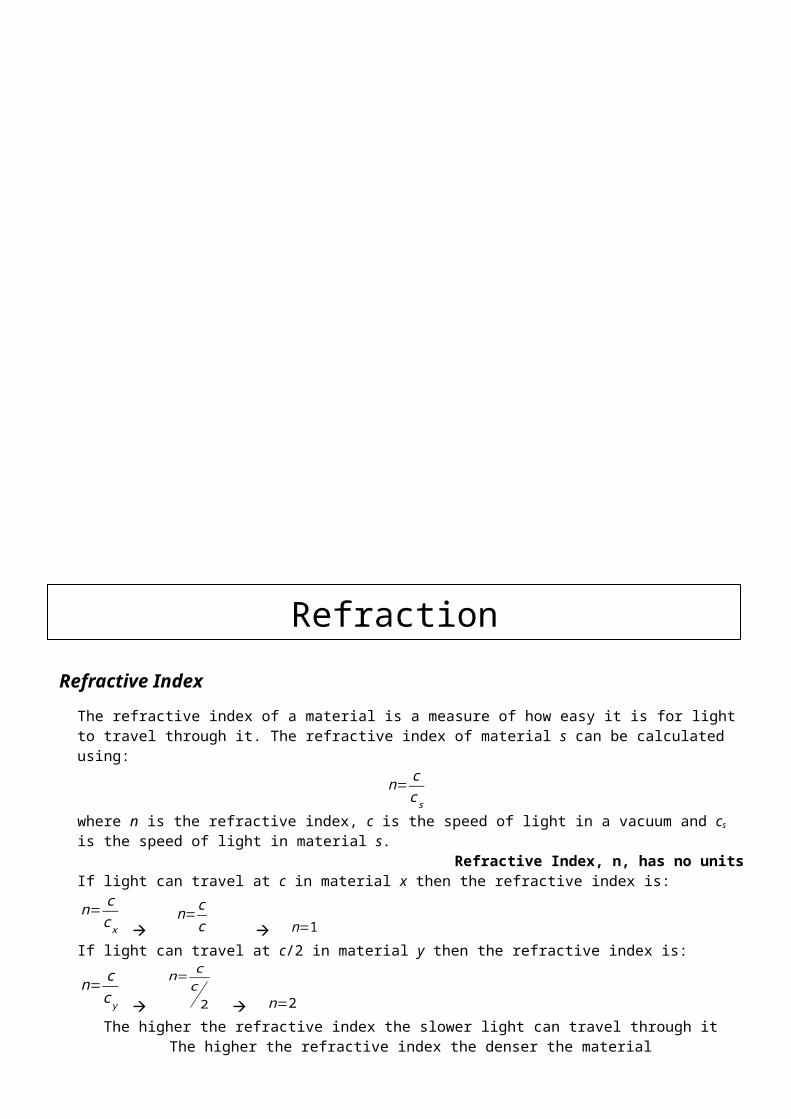
Refractive IndexThe refractive index of a material is a measure of how easy it is for light to travel through it. The refractive index of material s can be calculated using:
n= ccs
where n is the refractive index, c is the speed of light in a vacuum and cs is the speed of light in material s.
Refractive Index, n, has no units
If light can travel at c in material x then the refractive index is: n= c
cx n= c
c n=1
If light can travel at c/2 in material y then the refractive index is:n= c
c y
n= cc
2 n=2
Refraction
The higher the refractive index the slower light can travel through itThe higher the refractive index the denser the material
Bending LightWhen light passes from one material to another it is not only the speed of the light that changes, the direction can change too. If the ray of light is incident at 90° to the material then there is no change in direction, only speed.It may help to imagine the front of the ray of light as the front of a car to determine the direction the light will bend. Imagine a lower refractive index as grass and a higher refractive index at mud.
Entering a Denser MaterialThe car travels on grass until tyre A reaches the mud. It is harder to move through mud so A slows down but B can keep moving at the same speed as before. The car now points in a new direction. Denser material – higher refractive index – bends towards the Normal
Entering a Less Dense MaterialThe car travels in mud until tyre A reaches the grass. It is easier to move across grass so A can speed up but B keeps moving at the same speed as before. The car now points in a new direction. Less dense material – lower refractive index – bends away from the Normal
Relative Refractive IndexWhenever two materials touch the boundary between them will have a refractive index dependent on the refractive indices of the two materials. We call this the relative refractive index.When light travels from material 1 to material 2 we can calculate the relative refractive index of the boundary using any of the following:
1 n2=n2
n1=
c1
c2=
sin θ1
sin θ2Relative Refractive Index, 1n2, has no units
Some questions may involve light travelling through several layers of materials. Tackle one boundary at a time.
w ng=ng
nw=
cw
cg=
sin θw
sin θg ---------------------------->
g na=na
ng=
cg
ca=
sinθg
sinθa ---------------------------->
Refraction1. Monochromatic light passes from air into water. Which one of the
following statements is true?
A The velocity, frequency and wavelength all change
B The velocity and frequency change but not the wavelength
C The velocity and wavelength change but not the frequency
D The frequency and wavelength change but not the velocity
2 A ray of light, travelling in air, passes into a glass block at an angle of 65° to the normal in air. The refractive index of glass is 1.5.Calculate the angle of refraction.
3 A ray of light, travelling in glass, passes through the glass–air boundary at an angle of 25° to the normal in the glass. The refractive index of glass is 1.5.Calculate the angle of refraction.
4 A ray of light, travelling in air, passes into water. The angle of refraction is 23°. The refractive index of water is 1.33.Calculate the angle of incidence.
5 The refractive index of acrylic glass is 1.49. The speed of light in air is approximately 3 108 ms−1.Calculate the speed of light in acrylic glass.
6 A ray of light, travelling in liquid water, passes into an ice cube at an angle of 25.5° to the normal in water. The ray of light is refracted to an angle of 25.9° to the normal in the ice. The refractive index of liquid water is 1.33.
Calculate the refractive index of ice.7 The speed of light in a certain glass is 1.8 108 m s-1. What is the refractive index
of the glass?8 The refractive index of diamond is 2.4. What is the speed of light in diamond?9 The refractive index changes with the colour of the light leading to dispersion. If
the refractive index for blue light in a certain glass is 1.639 and for red light is 1.621, calculate the angle between the rays if they were both incident at 50o.
10Find the relative refractive index from glass to water if the absolute indices are 1.5 and 1.3 respectively.
1 C2 37° to two significant figures (37.2°) (2 marks)3 39° to two significant figures (39.3°) (2 marks)4 31° to two significant figures (31.3°) (2 marks)5 2 108
ms−1 (2 marks)6 25.9° to three significant figures (3 marks)7 ng = c/cg = 3.0 108 / 1.8 108 = 1.67 (no unit as refractive index is a number)8 nd = c/cd so cd = c/nd = 3 108 m s-1 / 2.4 = 1.25 10 8 m s-1
9 For blue light, sin q = sin 50° / 1.639 = 0.4674 and q = 27.86o For red light, sin q = sin 50° / 1.621 = 0.4726 and q = 27.20o
The angle between the two rays is the difference so = 0.86o. [NB with a prism red is deviated least (“red tries to go straight ahead” pronounce ‘ahead’ as “a red”), useful to learn. The diffraction grating spreads out the colours with blue deviated most.)
10 gnw = nw / ng = 1.3 / 1.5 = 0.87
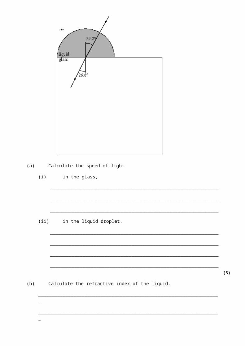
Q1.The diagram below shows a liquid droplet placed on a cube of glass. A ray of light from air, incident normally on to the droplet, continues in a straight line and is refracted at the liquid to glass boundary as shown.refractive index of the glass = 1.45
(a) Calculate the speed of light
(i) in the glass,
______________________________________________________________
______________________________________________________________
______________________________________________________________
(ii) in the liquid droplet.
______________________________________________________________
______________________________________________________________
______________________________________________________________
______________________________________________________________(3)
(b) Calculate the refractive index of the liquid.
___________________________________________________________________
___________________________________________________________________
___________________________________________________________________
___________________________________________________________________
___________________________________________________________________(2)
(Total 5 marks)
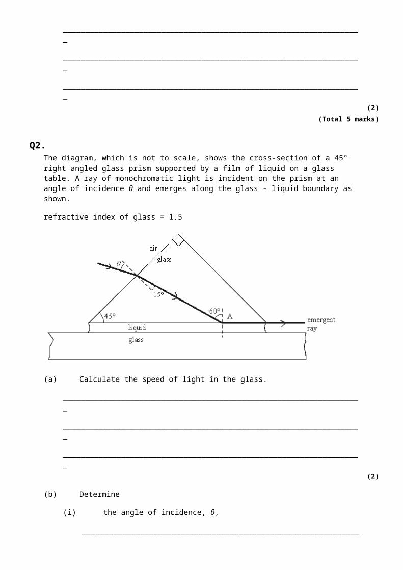
Q2.The diagram, which is not to scale, shows the cross-section of a 45° right angled glass prism supported by a film of liquid on a glass table. A ray of monochromatic light is incident on the prism at an angle of incidence θ and emerges along the glass - liquid boundary as shown.
refractive index of glass = 1.5
(a) Calculate the speed of light in the glass.
___________________________________________________________________
___________________________________________________________________
___________________________________________________________________(2)
(b) Determine
(i) the angle of incidence, θ,
______________________________________________________________
______________________________________________________________
______________________________________________________________
(ii) the refractive index of the liquid.
______________________________________________________________
______________________________________________________________
______________________________________________________________
______________________________________________________________(5)
(Total 7 marks)
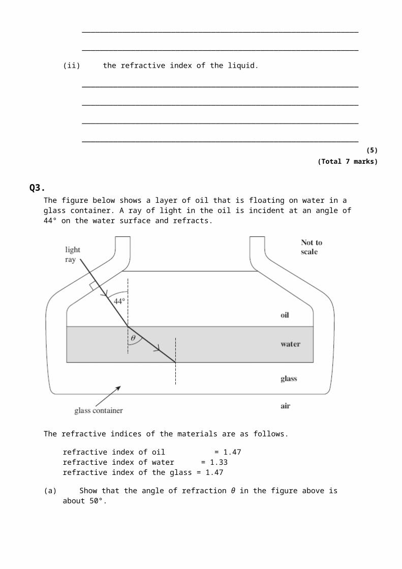
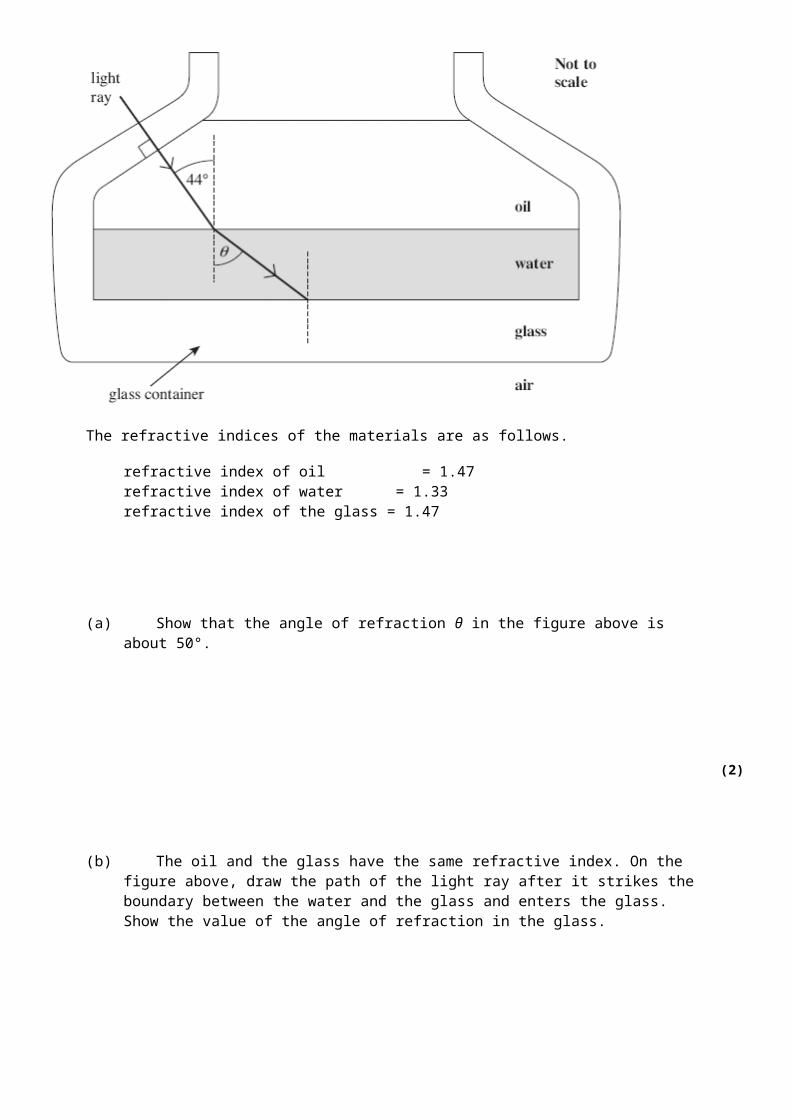
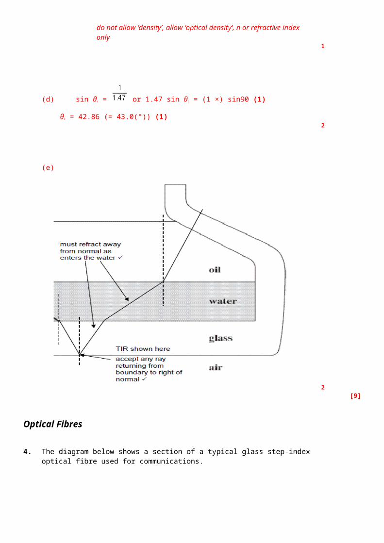
Q3.The figure below shows a layer of oil that is floating on water in a glass container. A ray of light in the oil is incident at an angle of 44° on the water surface and refracts.
The refractive indices of the materials are as follows.
refractive index of oil = 1.47refractive index of water = 1.33refractive index of the glass = 1.47
(a) Show that the angle of refraction θ in the figure above is about 50°.
(2)
(b) The oil and the glass have the same refractive index. On the figure above, draw the path of the light ray after it strikes the boundary between the water and the glass and enters the glass. Show the value of the angle of refraction in the glass.
(2) (Total 4 marks)
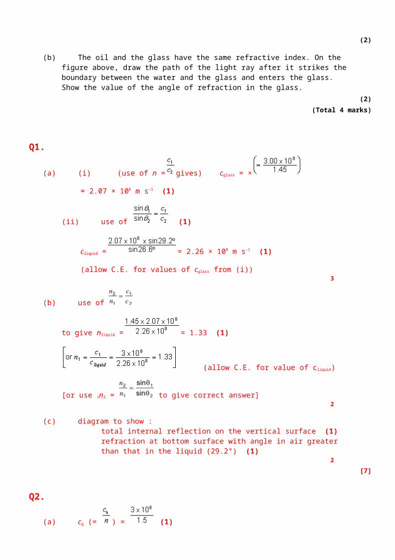
Q1.
(a) (i) (use of n = gives) cglass = ×

= 2.07 × 10⁸ m s–1 (1)
(ii) use of (1)
cliquid = = 2.26 × 10⁸ m s–1 (1)
(allow C.E. for values of cglass from (i))3
(b) use of
to give nliquid = = 1.33 (1)
(allow C.E. for value of cliquid)
[or use 1n2 = to give correct answer]2
(c) diagram to show : total internal reflection on the vertical surface (1) refraction at bottom surface with angle in air greater than that in the liquid (29.2°) (1)
2[7]
Q2.
(a) cg (= ) = (1)
= 2.0 × 10⁸ m s–1 (1)2
(b) (i) sin 1 (= n sin 2) = 1.5 × sin 15 (1)1 = 23° (1) (22.8°)
(ii) use of (1) (or equivalent)
n2 = (1)
= 1.3 (1)5
[7]
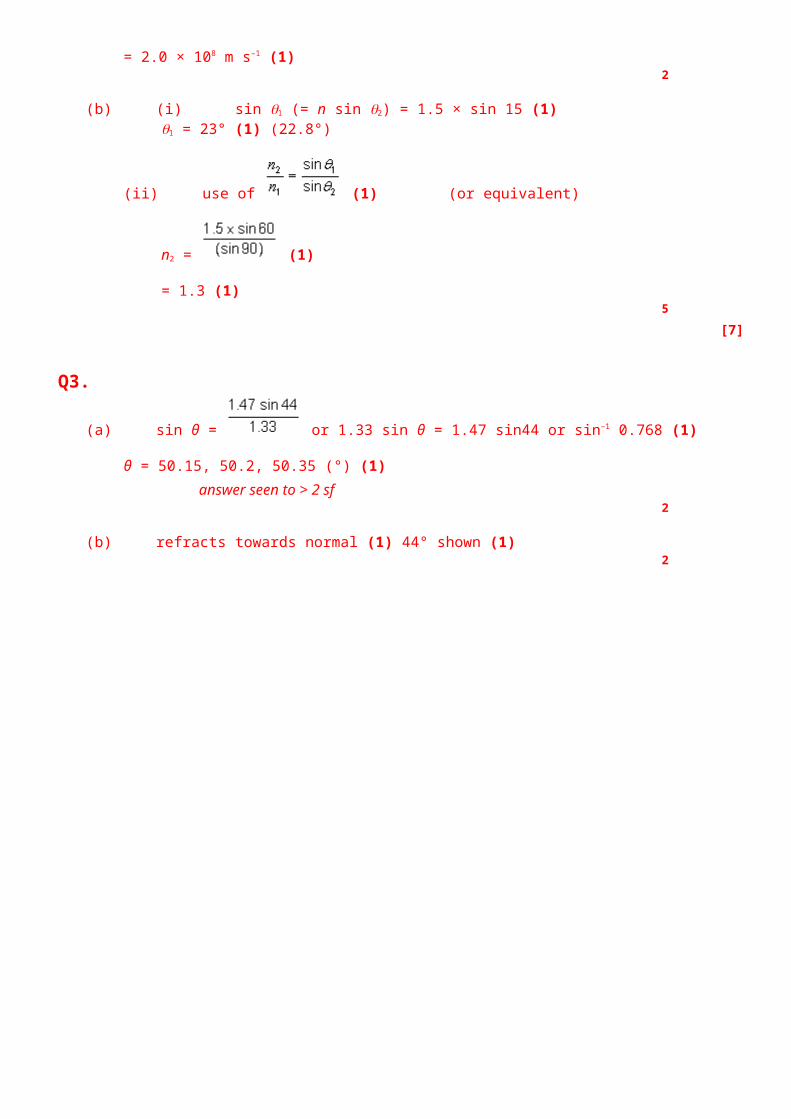
Q3.
(a) sin θ = or 1.33 sin θ = 1.47 sin44 or sin–1 0.768 (1)
θ = 50.15, 50.2, 50.35 (°) (1)answer seen to > 2 sf
2
(b) refracts towards normal (1) 44° shown (1)2
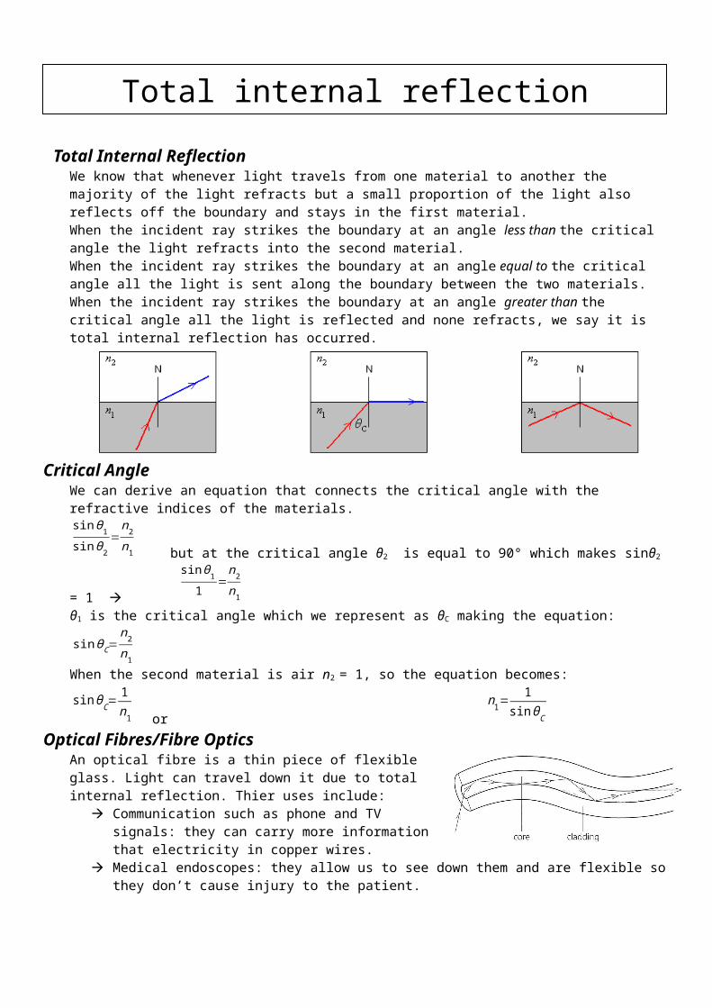
Total Internal Reflection We know that whenever light travels from one material to another the majority of the light refracts but a small proportion of the light also reflects off the boundary and stays in the first material.When the incident ray strikes the boundary at an angle less than the critical angle the light refracts into the second material.When the incident ray strikes the boundary at an angle equal to the critical angle all the light is sent along the boundary between the two materials.When the incident ray strikes the boundary at an angle greater than the critical angle all the light is reflected and none refracts, we say it is total internal reflection has occurred.
Critical Angle We can derive an equation that connects the critical angle with the refractive indices of the materials.
Total internal reflection
sin θ1
sin θ2=
n2
n1 but at the critical angle θ2 is equal to 90° which makes sinθ2 = 1 sin θ1
1=
n2
n1
θ1 is the critical angle which we represent as θC making the equation: sin θC=
n2
n1
When the second material is air n2 = 1, so the equation becomes: sin θC=
1n1 or
n1=1
sin θC
Optical Fibres/Fibre OpticsAn optical fibre is a thin piece of flexible glass. Light can travel down it due to total internal reflection. Thier uses include:
Communication such as phone and TV signals: they can carry more information that electricity in copper wires.
Medical endoscopes: they allow us to see down them and are flexible so they don’t cause injury to the patient.
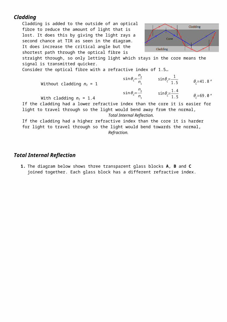
CladdingCladding is added to the outside of an optical fibre to reduce the amount of light that is lost. It does this by giving the light rays a second chance at TIR as seen in the diagram.It does increase the critical angle but the shortest path through the optical fibre is straight through, so only letting light which stays in the core means the signal is transmitted quicker. Consider the optical fibre with a refractive index of 1.5…
Without cladding n2 = 1 sin θC=
n2
n1 sin θC=
11 .5 θC=41.8 °
With cladding n2 = 1.4 sin θC=
n2
n1 sin θC=
1 .41 .5 θC=69. 0 °
If the cladding had a lower refractive index than the core it is easier for light to travel through so the light would bend away from the normal, Total Internal Reflection.If the cladding had a higher refractive index than the core it is harder for light to travel through so the light would bend towards the normal, Refraction.
Total Internal Reflection1. The diagram below shows three transparent glass blocks A, B and C joined
together. Each glass block has a different refractive index.
(a) State the two conditions necessary for a light ray to undergo total internal reflection at the boundary between two transparent media.
condition 1 .....................................................................................................
........................................................................................................................
condition 2 .....................................................................................................
........................................................................................................................(2)
(b) Calculate the speed of light in glass A.
refractive index of glass A = 1.80
speed of light ..................................... ms−1
(2)
(c) Show that angle is about 300.
(2)
(d) The refractive index of glass C is 1.40.
Calculate the critical angle between glass A and glass C.
critical angle ................................. degrees(2)
(e) (i) State and explain what happens to the light ray when it reaches the boundary between glass A and glass C.
...............................................................................................................
...............................................................................................................
...............................................................................................................(2)
(ii) On the diagram above continue the path of the light ray after it strikes the boundary between glass A and glass C.
(1)(Total 11 marks)
1.(a) n1 > n2 Allow correct reference to ‘optical density’
(incident) angle > critical angle (allow θc not ‘c’)OR critical angle must be exceeded
Allow nA > nB
Do not allow: ‘angle passes the critical angle’2
(b)
For second mark, don’t allow 1.6 × 10⁸
Allow 1.66 × 10⁸ or 1.70 × 10⁸
Allow 1.6. × 108
(= 1.667 × 10 8) = 1.67 × 10⁸ (ms−1) 2
(c) sin72 = 1.80sin θ
Correct answer on its own gets both marks
θ = 31.895 = 31.9 correct answer >= 2sf seen Do not allow 31 for second markAllow 31.8 − 32
2
(d) 1.80 sin θc=1.40 OR θc = 51.058 = 51.1 ° (accept 51)
Correct answer on its own gets both marksDon’t accept 50 by itself
2
OR = 0.778
(e) (i) 22 + their (c) (22 + 31.9 = 53.9) 53.9 > (51.1) critical angle
If c + 22 < d then TIR expectedIf c + 22 > d then REFRACTION expected
ORc + 22 c ) ecf from (c) and (d)angle less than critical angle
Allow max 1 for ‘TIR because angle > critical angle’ only if their d > c + 22
2
(ii) TIR angle correct ecf from e(i) for refraction answer
Tolerance: horizontal line from normal on the right / horizontal line from top of lower arrow.If ei not answered then ecf (d). If ei and d not answered then ecf c
1[11]
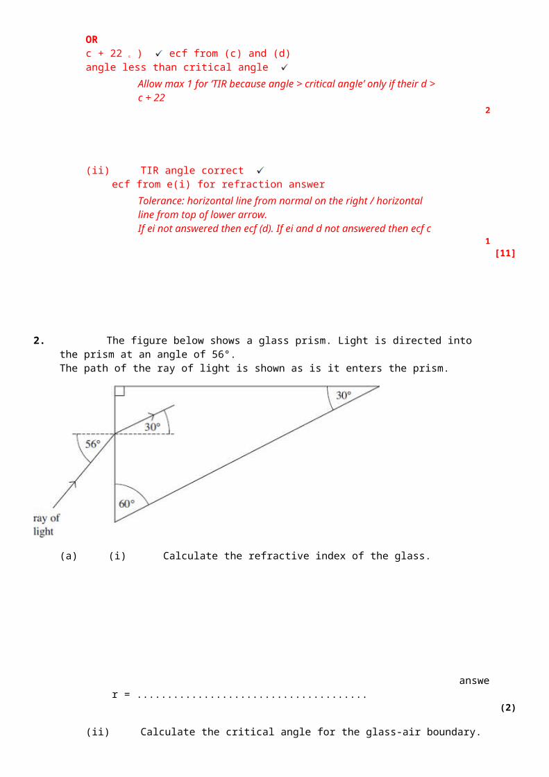
2. The figure below shows a glass prism. Light is directed into the prism at an angle of 56°.The path of the ray of light is shown as is it enters the prism.
(a) (i) Calculate the refractive index of the glass.
answer = ......................................(2)
(ii) Calculate the critical angle for the glass-air boundary.
answer = ......................... degrees(2)
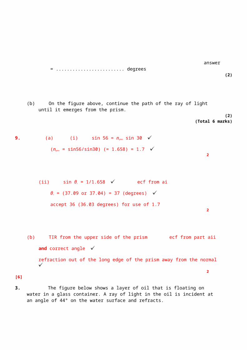
(b) On the figure above, continue the path of the ray of light until it emerges from the prism.
(2)(Total 6 marks)
9. (a) (i) sin 56 = nglass sin 30
(nglass = sin56/sin30) (= 1.658) = 1.7 2
(ii) sin θc = 1/1.658 ecf from ai
θc = (37.09 or 37.04) = 37 (degrees)
accept 36 (36.03 degrees) for use of 1.7
2
(b) TIR from the upper side of the prism ecf from part aii
and correct angle
refraction out of the long edge of the prism away from the normal 2
[6]
3. The figure below shows a layer of oil that is floating on water in a glass container. A ray of light in the oil is incident at an angle of 44° on the water surface and refracts.
The refractive indices of the materials are as follows.
refractive index of oil = 1.47refractive index of water = 1.33refractive index of the glass = 1.47
(a) Show that the angle of refraction θ in the figure above is about 50°.
(2)
(b) The oil and the glass have the same refractive index. On the figure above, draw the path of the light ray after it strikes the boundary between the water and the glass and enters the glass. Show the value of the angle of refraction in the glass.
(2)
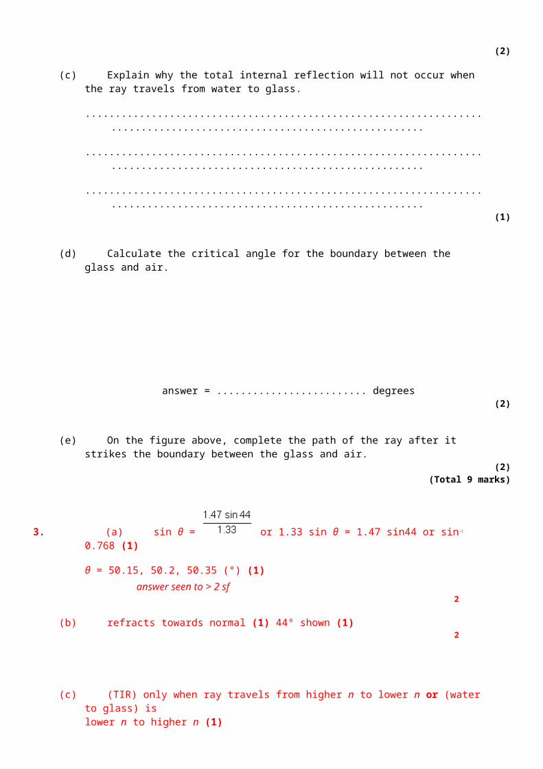
(c) Explain why the total internal reflection will not occur when the ray travels from water to glass.
......................................................................................................................
......................................................................................................................
......................................................................................................................(1)
(d) Calculate the critical angle for the boundary between the glass and air.
answer = ......................... degrees(2)
(e) On the figure above, complete the path of the ray after it strikes the boundary between the glass and air.
(2)(Total 9 marks)
3. (a) sin θ = or 1.33 sin θ = 1.47 sin44 or sin–1 0.768 (1)
θ = 50.15, 50.2, 50.35 (°) (1)answer seen to > 2 sf
2
(b) refracts towards normal (1) 44° shown (1)2
(c) (TIR) only when ray travels from higher n to lower n or (water to glass) islower n to higher n (1)
do not allow ‘density’, allow ‘optical density’, n or refractive index only
1
(d) sin θc = or 1.47 sin θc = (1 ×) sin90 (1)
θc = 42.86 (= 43.0(°)) (1)2
(e)
2[9]
Optical Fibres
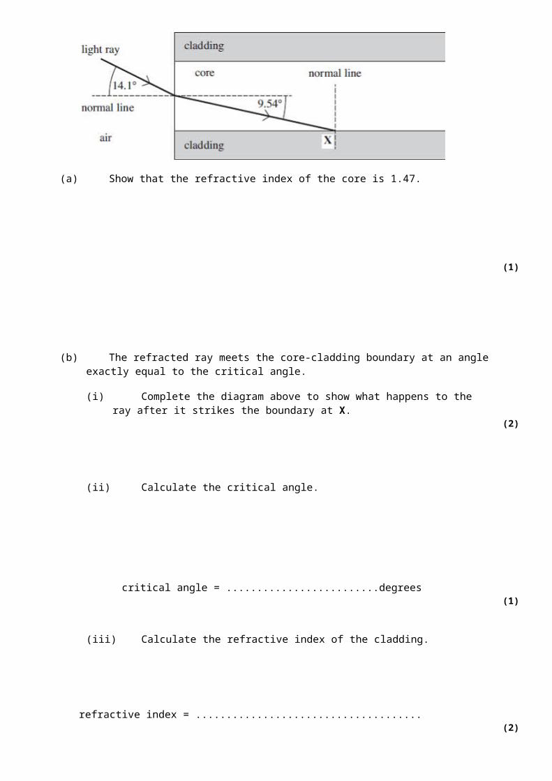
4. The diagram below shows a section of a typical glass step-index optical fibre used for communications.

(a) Show that the refractive index of the core is 1.47.
(1)
(b) The refracted ray meets the core-cladding boundary at an angle exactly equal to the critical angle.
(i) Complete the diagram above to show what happens to the ray after it strikes the boundary at X.
(2)
(ii) Calculate the critical angle.
critical angle = .........................degrees(1)
(iii) Calculate the refractive index of the cladding.
refractive index = .....................................(2)
4. (a) (n =) OR 0.2436 / 0.1657 working must be seen0.24 / 0.17 = 1.41 is not acceptable
AND ( = 1.4699) = 1.47 given correctly to 3 or more significant figuresWatch for:14.1 / 9.54 = 1.478
1
(b) (i) ray goes along the boundary Deviation by no more than 1mm by the end of the diagram.
(partial) reflection shown (allow dotted or solid line. This mark can be awarded if TIR is shown)
Tolerance: 70° to 85° to normal or labelled e.g. θ and θ, etc2
(ii) (90 − 9.54 = ) 80.46 or 80.5 (° ) ( allow 80° )Don’t allow 81 degrees
1
(iii) (n = nc sin θ)allow 80 or 81 degrees here
= 1.47 sin 80.46° ecf bii
=1.45 (1.4496)Correct answer gains both marks
2
5.(a) Describe the structure of a step-index optical fibre outlining the purpose of
the core and the cladding.
___________________________________________________________________
___________________________________________________________________
___________________________________________________________________
___________________________________________________________________
___________________________________________________________________
___________________________________________________________________
___________________________________________________________________
___________________________________________________________________
___________________________________________________________________(3)
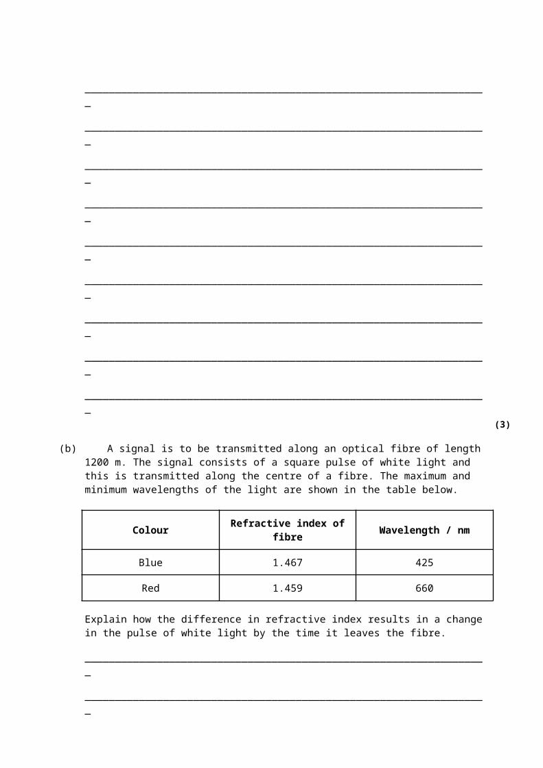
(b) A signal is to be transmitted along an optical fibre of length 1200 m. The signal consists of a square pulse of white light and this is transmitted along the centre of a fibre. The maximum and minimum wavelengths of the light are
shown in the table below.
Colour Refractive index of fibre Wavelength / nm
Blue 1.467 425
Red 1.459 660
Explain how the difference in refractive index results in a change in the pulse of white light by the time it leaves the fibre.
___________________________________________________________________
___________________________________________________________________
___________________________________________________________________
___________________________________________________________________
___________________________________________________________________
___________________________________________________________________
___________________________________________________________________(2)
(c) Discuss two changes that could be made to reduce the effect described in part (b).
___________________________________________________________________
___________________________________________________________________
___________________________________________________________________
___________________________________________________________________
___________________________________________________________________
___________________________________________________________________
___________________________________________________________________(2)
(Total 7 marks)
Q5.(a) Core is transmission medium for em waves to progress (by total internal reflection) ✓
Allow credit for points scored on a clear labelled diagram.1
Cladding provides lower refractive index so that total internal reflection takes place ✓
1
And offers protection of boundary from scratching which could lead to light leaving the core. ✓
1
(b) Blue travels slower than red due to the greater refractive index
Red reaches end before blue, leading to material pulse broadening ✓The first mark is for discussion of refractive index or for calculation of time difference.
1
Alternative calculations for first mark
Time for blue = d / v = d / (c / n) = 1200 / (3 × 10⁸ / 1.467) = 5.87 × 10⁻⁶ s
Time for red = d / v = d / (c / n) = 1200 / (3 × 10⁸ / 1.459) = 5.84 × 10⁻⁶ s
Time difference = 5.87 × 10⁻⁶ – 5.84 × 10-6 = 3(.2) × 10-8 s ✓The second mark is for the link to material pulse broadening
1
(c) Discussions to include:
Use of monochromatic source so speed of pulse constant
Use of shorter repeaters so that the pulse is reformed before significant pulse broadening has taken place.
Use of monomode fibre to reduce multipath dispersion ✓ ✓Answer must make clear that candidate understands the distinction between modal and material broadening.
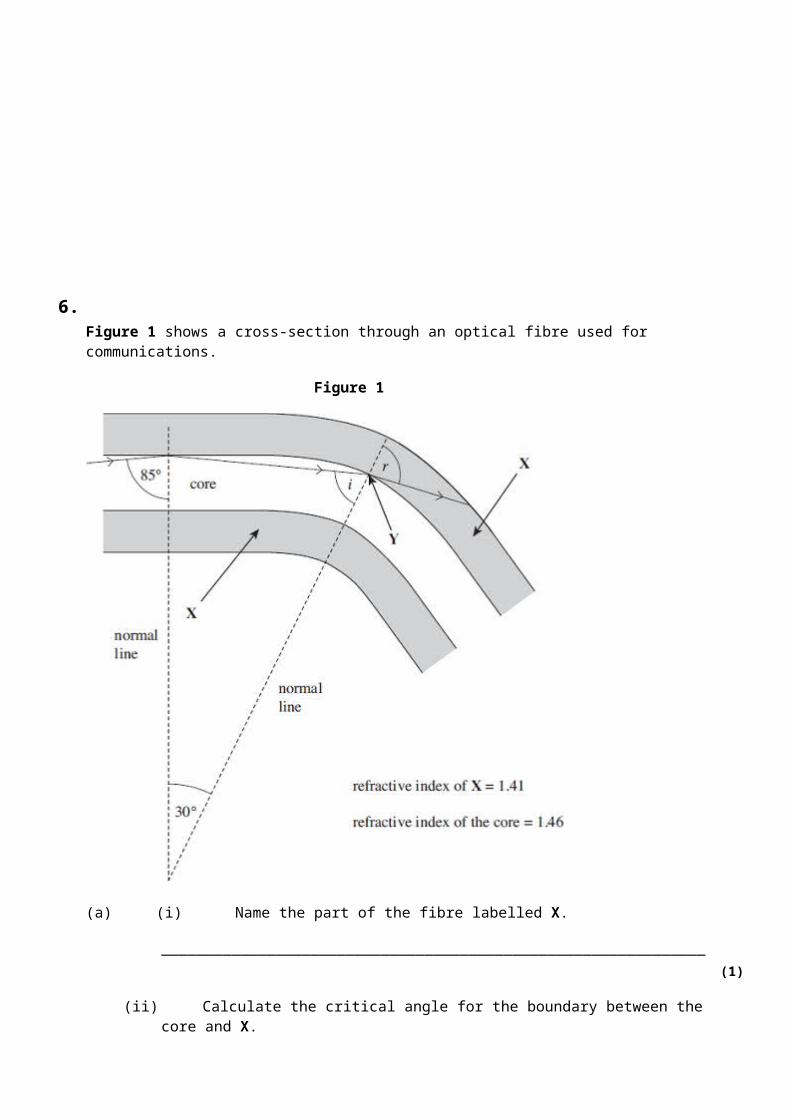
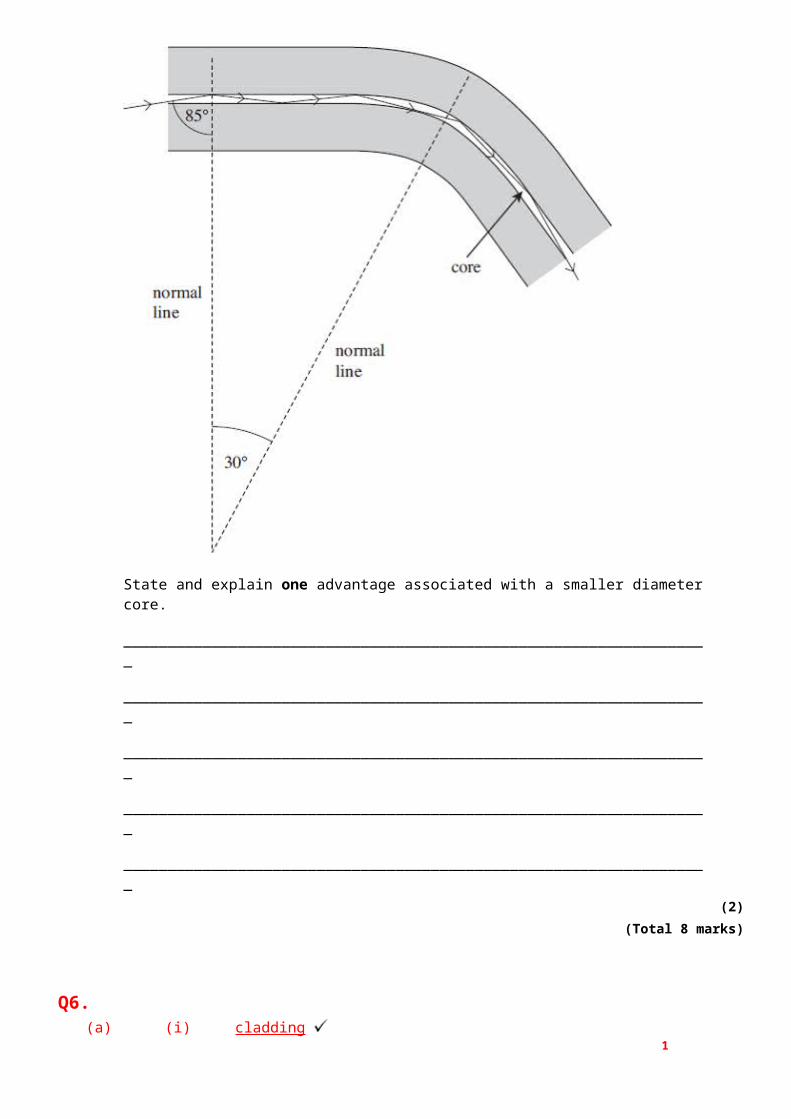
6.Figure 1 shows a cross-section through an optical fibre used for communications.
Figure 1
(a) (i) Name the part of the fibre labelled X.
______________________________________________________________(1)
(ii) Calculate the critical angle for the boundary between the core and X.
answer = ____________________degrees(2)
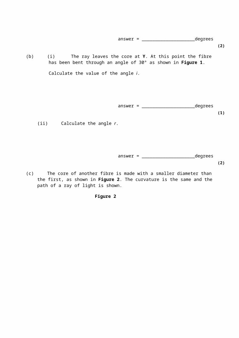
(b) (i) The ray leaves the core at Y. At this point the fibre has been bent through an angle of 30° as shown in Figure 1.
Calculate the value of the angle i.
answer = ____________________degrees(1)
(ii) Calculate the angle r.
answer = ____________________degrees(2)
(c) The core of another fibre is made with a smaller diameter than the first, as shown in Figure 2. The curvature is the same and the path of a ray of light is shown.
Figure 2
State and explain one advantage associated with a smaller diameter core.
___________________________________________________________________
___________________________________________________________________
___________________________________________________________________
___________________________________________________________________
___________________________________________________________________(2)
(Total 8 marks)
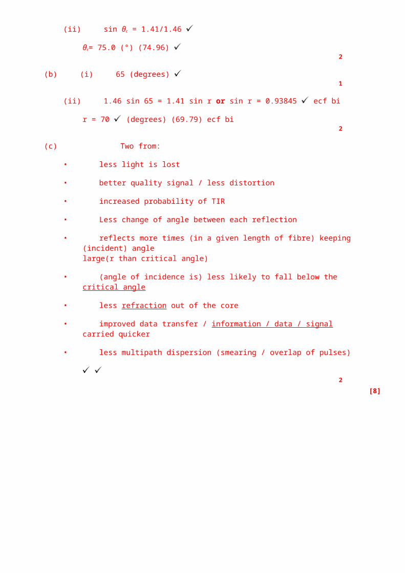
Q6.(a) (i) cladding
1
(ii) sin θc = 1.41/1.46
θc= 75.0 (°) (74.96) 2
(b) (i) 65 (degrees) 1
(ii) 1.46 sin 65 = 1.41 sin r or sin r = 0.93845 ecf bi
r = 70 (degrees) (69.79) ecf bi2
(c) Two from:
• less light is lost
• better quality signal / less distortion
• increased probability of TIR
• Less change of angle between each reflection
• reflects more times (in a given length of fibre) keeping (incident) anglelarge(r than critical angle)
• (angle of incidence is) less likely to fall below the critical angle
• less refraction out of the core
• improved data transfer / information / data / signal carried quicker
• less multipath dispersion (smearing / overlap of pulses)
2
[8]
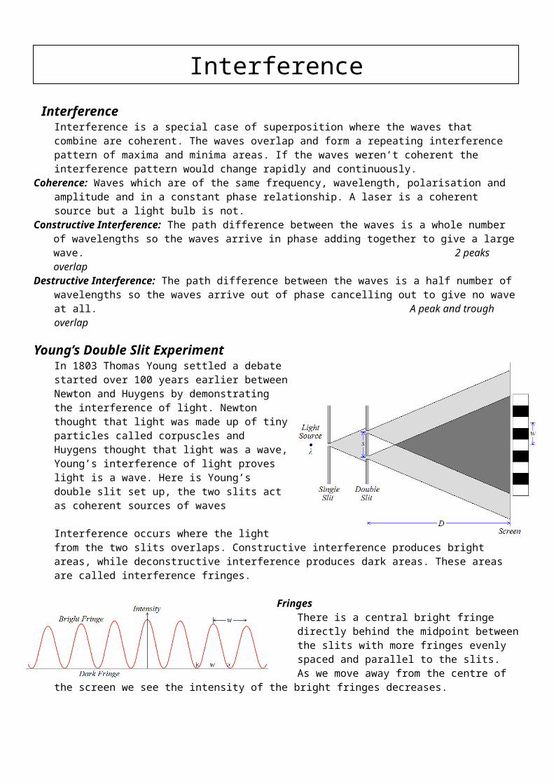
InterferenceInterference is a special case of superposition where the waves that combine are coherent. The waves overlap and form a repeating interference pattern of maxima and minima areas. If the waves weren’t coherent the interference pattern would change rapidly and continuously.
Coherence: Waves which are of the same frequency, wavelength, polarisation and amplitude and in a constant phase relationship. A laser is a coherent source but a light bulb is not.
Constructive Interference: The path difference between the waves is a whole number of wavelengths so the waves arrive in phase adding together to give a large wave. 2 peaks overlap
Destructive Interference: The path difference between the waves is a half number of wavelengths so the waves arrive out of phase cancelling out to give no wave at all. A peak and trough overlap
Young’s Double Slit ExperimentIn 1803 Thomas Young settled a debate started over 100 years earlier between Newton and Huygens by demonstrating the interference of light. Newton thought that light was made up of tiny particles called corpuscles and Huygens thought that light was a wave, Young’s interference of light proves light is a wave. Here is Young’s double slit set up, the two slits act as coherent sources of waves
Interference occurs where the light from the two slits overlaps. Constructive interference produces bright areas, while deconstructive interference produces dark areas. These areas are called interference fringes.
FringesThere is a central bright fringe directly behind the midpoint between the slits with more fringes evenly spaced and parallel to the slits.As we move away from the centre of the screen we see the intensity of the bright
fringes decreases.
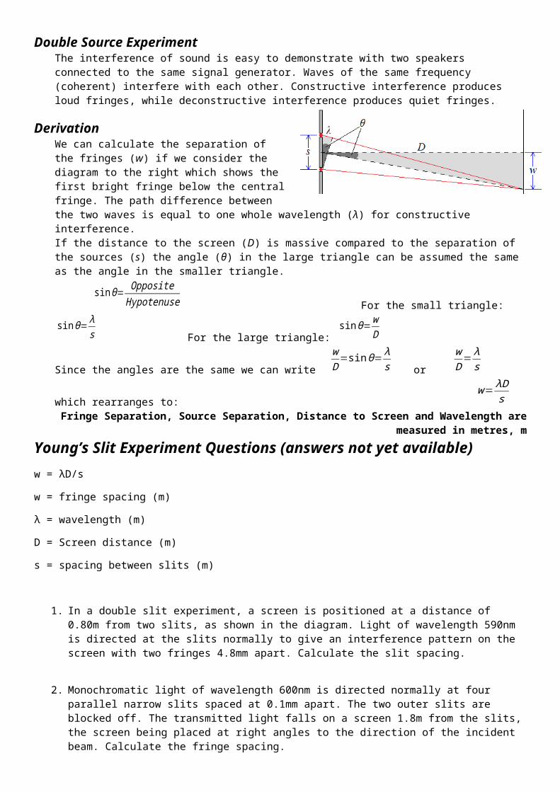
Double Source ExperimentThe interference of sound is easy to demonstrate with two speakers connected to the same signal generator. Waves of the same frequency (coherent) interfere with each other. Constructive interference produces loud fringes, while deconstructive interference produces quiet fringes.
DerivationWe can calculate the separation of the fringes (w) if we consider the diagram to the right which shows the first bright fringe below the central fringe. The path difference between the two waves is equal to one whole wavelength (λ) for constructive interference.
Interference
If the distance to the screen (D) is massive compared to the separation of the sources (s) the angle (θ) in the large triangle can be assumed the same as the angle in the smaller triangle.
sin θ= Opposite
Hypotenuse For the small triangle: sin θ= λ
s For the large triangle: sin θ=w
D
Since the angles are the same we can write wD=sin θ= λ
s or wD= λ
s which rearranges
to: w= λD
sFringe Separation, Source Separation, Distance to Screen and Wavelength are
measured in metres, mYoung’s Slit Experiment Questions (answers not yet available)w = λD/sw = fringe spacing (m)λ = wavelength (m)D = Screen distance (m)s = spacing between slits (m)
1. In a double slit experiment, a screen is positioned at a distance of 0.80m from two slits, as shown in the diagram. Light of wavelength 590nm is directed at the slits normally to give an interference pattern on the screen with two fringes 4.8mm apart. Calculate the slit spacing.
2. Monochromatic light of wavelength 600nm is directed normally at four parallel narrow slits spaced at 0.1mm apart. The two outer slits are blocked off. The transmitted light falls on a screen 1.8m from the slits, the screen being placed at right angles to the direction of the incident beam. Calculate the fringe spacing.
3. Use the equation for Young’s Slit experiment to explaina. With the slits closer together, the fringes are further apartb. Interference fringes for blue light are closer together than for red lightc. In an experiment to measure the wavelength of light, it is desirable to have the
screen as far as possible from the slits.
4. In a Young’s slit experiment, filters were placed in front of a white light source to investigate the effect of changing the wavelength of the light. At first a red filter was used (wavelength = 600nm) and the fringe separation was found to be 2.4mm. A blue filter was used (wavelength = 450mm). What would the fringe separation become?
5. Yellow sodium light of wavelength 589nm is used in a double-slit experiment. The slit separation is 0,2mm and the screen is placed 1.20m from the slits. What will be the separation of the fringes which appear on the screen?
6. Interference fringes are formed on a screen when monochromatic light is passed through two narrow slits which are close together. State how, if at all, and explain why the separation of the fringes increases if
a. The screen is moved closer towards the slits
b. The slits are made narrower but the separation is unchangedc. A more intense light source is usedd. Light of longer wavelength is usede. The separation of the slits is increased
7. In a double slit experiment using light from a helium-neon laser (wavelength = 630 nm), a student obtained the following data.Width of 10 fringes = 1.5cmSeparation of slits = 1.0mmSlit to screen distance = 2.40m
If the student moved the screen to s distance of 4.8m, what would the fringe separation be?
Q1.A laser emits light of wavelength 6.3 × 10⁻⁷ m and is used to illuminate a double slit which has a separation of 2.4 × 10⁻⁴ m. Interference fringes are observed 4.2 m from the slits.
(a) Calculate the fringe separation.(2)
(b) The double slit acts as a pair of coherent sources. Explain what is meant by coherent sources.
___________________________________________________________________
___________________________________________________________________
___________________________________________________________________(2)
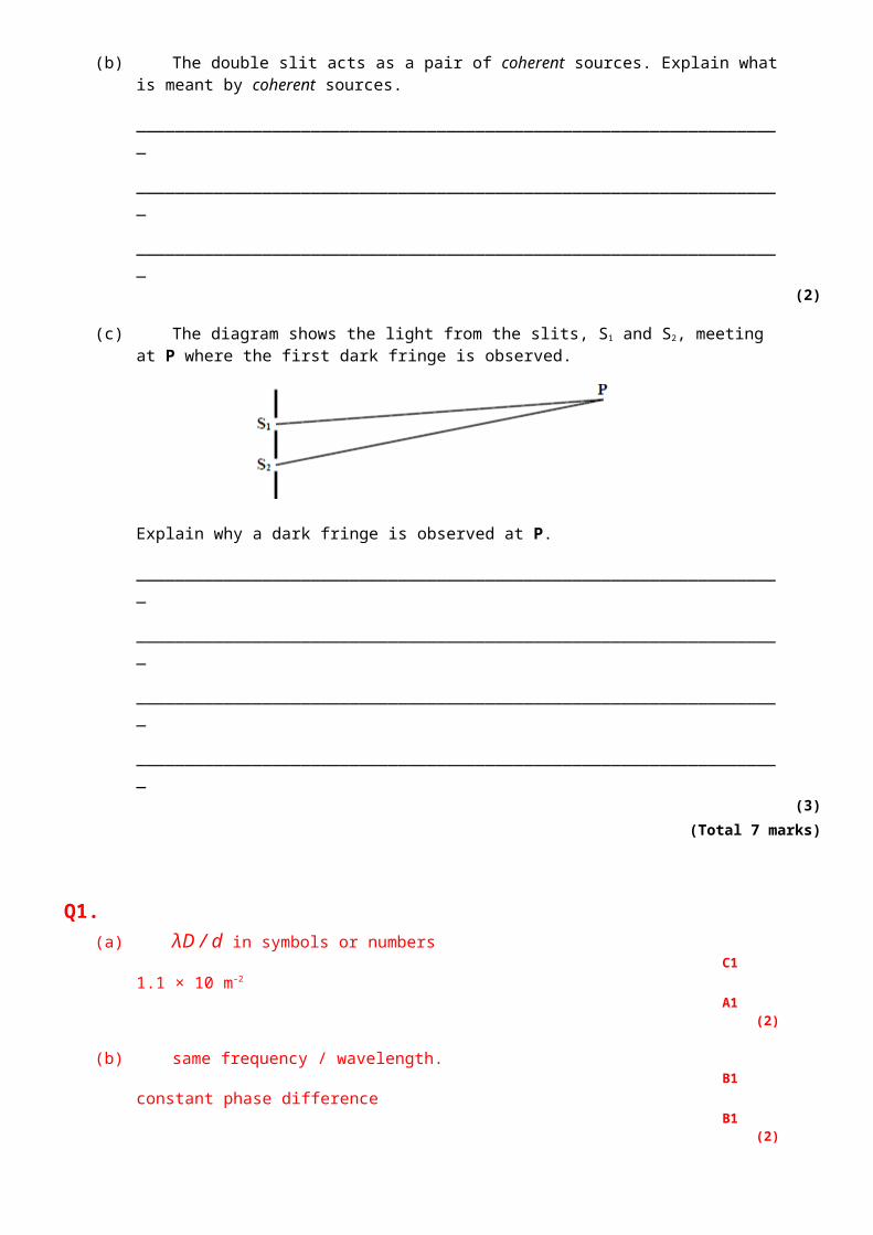
(c) The diagram shows the light from the slits, S1 and S2, meeting at P where the first dark fringe is observed.
Explain why a dark fringe is observed at P.
___________________________________________________________________
___________________________________________________________________
___________________________________________________________________
___________________________________________________________________(3)
(Total 7 marks)
Q1.(a) λD / d in symbols or numbers
C11.1 × 10 m–2
A1(2)
(b) same frequency / wavelength.B1
constant phase differenceB1
(2)
(c) Reference to out of phaseC1
phase difference is 180° or π / path difference is λ2 / explanation ofC1
antiphase eg crest meets troughA1
destructive interference / description of cancelling outB1
(3)[7]
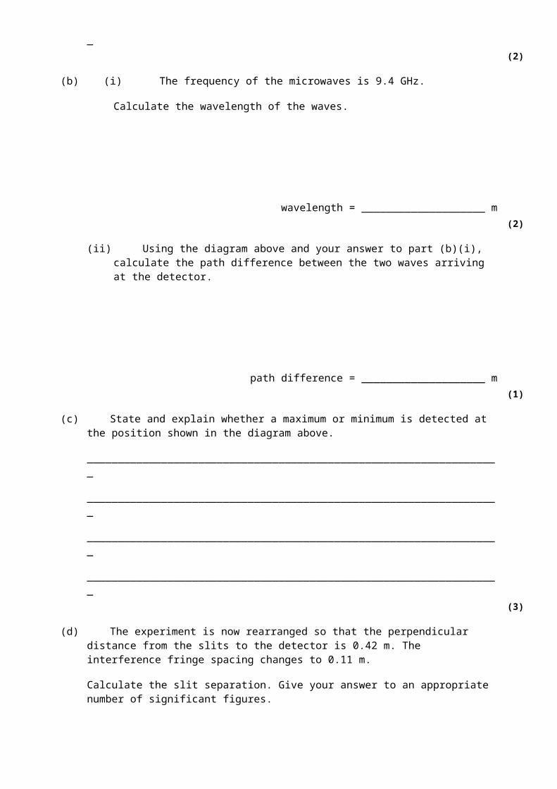
Q2.The diagram below shows the paths of microwaves from two narrow slits, acting as coherent sources, through a vacuum to a detector.
(a) Explain what is meant by coherent sources.
___________________________________________________________________
___________________________________________________________________
___________________________________________________________________
___________________________________________________________________(2)
(b) (i) The frequency of the microwaves is 9.4 GHz.
Calculate the wavelength of the waves.
wavelength = ____________________ m(2)
(ii) Using the diagram above and your answer to part (b)(i), calculate the path difference between the two waves arriving at the detector.
path difference = ____________________ m(1)
(c) State and explain whether a maximum or minimum is detected at the position shown in the diagram above.
___________________________________________________________________
___________________________________________________________________
___________________________________________________________________
___________________________________________________________________(3)
(d) The experiment is now rearranged so that the perpendicular distance from the slits to the detector is 0.42 m. The interference fringe spacing changes to 0.11 m.
Calculate the slit separation. Give your answer to an appropriate number of significant figures.
slit separation = ____________________ m(3)
(e) With the detector at the position of a maximum, the frequency of the microwaves is now doubled. State and explain what would now be detected by the detector in the same position.
___________________________________________________________________
___________________________________________________________________
___________________________________________________________________
___________________________________________________________________(3)
(Total 14 marks)
Q2.(a) same wavelength / frequency
constant phase relationship allow ‘constant phase difference’ but not ‘in phase’2
(b) (i) ( λ = )Use of speed of sound gets zero
3.00 × 108 = 9.4 (109) λ OR
= 3.2 × 10⁻² (3.19 × 10⁻² m) Allow 0.03
2
(ii) 3.2 × 10⁻² (m) ecf from biDon’t allow ‘1 wavelength’, 1λ, etcDo not accept: zero, 2 , 360 °
1
(c) maximum (at position shown) allow constructive superposition. ‘Addition’ is not enough
constructive interference / reinforcement
ecf for ‘minimum’ or for reference to wrong maximum
(the waves meet) ‘in step’ / peak meets peak / trough meets trough / path difference is (n) λ / in phase
3
(d) s = Don’t allow use of the diagram shown as a scale diagram
ecf biDo not penalise s and w symbols wrong way round in working if answer is correct.
= 0.12 (0.1218 m) Correct answer gains first two marks.
= any 2sf number Independent sf mark for any 2 sf number
3
(e) a maximum Candidates stating ‘ minimum ’ can get second mark only
(f × 2 results in) λ/2
path difference is an even number of multiples of the new wavelength ( 2n λ new )
allow ‘path difference is nλ’ / any even number of multiples of the new λ quoted e.g. ‘path difference is now 2 λ’
3
[14]Diffraction
When waves pass through a gap they spread out, this is called diffraction. The amount of diffraction depends on the size of the wavelength compared to the size of the gap. In the first diagram the gap is several times wider than the wavelength so the wave only spreads out a little. In the second diagram the gap is closer to the wavelength so it begins to spread out more. In the third diagram the gap is now roughly the same size as the wavelength so it spreads out the most.
Diffraction PatternsHere is the diffraction pattern from light being shone through a single slit. There is a central maximum that is twice as wide as the others and by far the brightest. The outer fringes are dimmer and of equal width.If we use three, four or more slits the interference maxima become brighter, narrower and further apart.
Diffraction GratingA diffraction grating is a series of narrow, parallel slits. They usually have around 500 slits per mm.When light shines on the diffraction grating several bright sharp lines can be seen as shown in the diagram to the right.The first bright line (or interference maximum) lies directly behind where the light shines on the grating. We call this the zero-order maximum. At an angle of θ from this lies the next bright line called the first-order maximum and so forth.
The zero-order maximum (n=0)
Diffraction
There is no path difference between neighbouring waves. They arrive in phase and interfere constructively.
The first-order maximum (n=1)There is a path difference of 1 wavelength between neighbouring waves. They arrive in phase and interfere constructively.
The second-order maximum (n=2)There is a path difference of 2 wavelengths between neighbouring waves. They arrive in phase and interfere constructively.
Between the maximaThe path difference is not a whole number of wavelengths so the waves arrive out of phase and interfere destructively.
DerivationThe angle to the maxima depends on the wavelength of the light and the separation of the slits. We can derive an equation that links them by taking a closer look at two neighbouring waves going to the first-order maximum.The distance to the screen is so much bigger than the distance between two slits that emerging waves appear to be parallel and can be treated that way.Consider the triangle to the right.
sin θ= OppositeHypotenuse
sin θ= λd d sin θ= λ
For the nth order the opposite side of the triangle becomes nλ, making the equation:d sin θ=nλ
Grating calculations
A grating is labelled '500 lines per mm'.1. Calculate the spacing of the slits in the grating.2. Monochromatic light is aimed straight at the grating and is found to
give a first-order maximum at 15°. Calculate the wavelength of the light source.
3. Calculate the position of the first-order maximum when red light of wavelength 730 nm is shone directly at the grating.
4. The longest visible wavelength is that of red light with λ = 750 nm. The shortest visible wavelength is violet where λ = 400nm. Use this information to calculate the width of the angle into which the first-order spectrum is spread out when white light is shone onto the grating.
A grating is illuminated with a parallel beam of light of wavelength 550 nm. The first-order maximum is in a direction making an angle of 20° with the straight-through direction.5. Calculate the spacing of the grating slits. 6. What would be the angle of the first-order maximum if a grating of
slit spacing of 2.5 × 10⁻⁶ m were used with the same light source?
7. Calculate the wavelength of light that would give a second-order maximum at θ = 32° with a grating of slit spacing 2.5 × 10⁻⁶ m.
8. A monochromatic laser beam of wavelength of 600 nm is directed at a diffraction grating with slit spacing 2.5 μm. Find the angle from the centre of the 2nd order fringe produced.
9. Monochromatic light of wavelength 450 nm is directed at a diffraction grating. The 1st order maxima is observed at an angle of 21.2°. What is the spacing of the lines in the diffraction grating?
10. Monochromatic light is directed at a diffraction grating with 500 lines per mm. The 2nd order maxima is detected at an angle of 42° from the straight-through position. What is the light’s wavelength?
11. Light of wavelength 610 nm is directed at a diffraction grating that has 700 lines per mm. Calculate the number of diffracted orders produced.
1. Number of slits per mm = 500. Therefore, slit spacing = 1 / 500 = 0.002 mm =
2 x 10⁻⁶ m.
2.
.sin ndn
Therefore
nm.520orm102.515sin102 76
3.
.sin ndn
Therefore
358.0/sin d
from which = 21.
4.
.sin dn
For red light:
0.375m102/m105.7/sin 67r d
angle r 22.
For violet light:
sin v = λ / d = 4.0 x 10⁻⁷ m / 2 x 10⁻⁶ m = 0.20
angle v 12. The difference in angle is 10.
5.
m.101.60.342/m105.5
.sin/67
d
d
6.
0.22.m102.5/m105.5sin
./sin67
d
Thus
.7.12
7.
.sin dn
Thus
nm.660m106.6
2/)0.530m105.2(
2/)32sinm105.2(
7
6
6
8. 28.7°
9. 1.2 μm
10. 670 nm
11. 2
Q1.For a plane transmission diffraction grating, the diffraction grating equation for the first order beam is:
λ = d sin θ
(a) The figure below shows two of the slits in the grating. Label the figure below with the distances d and λ.
(2)
(b) State and explain what happens to the value of angle θ for the first order beam if the wavelength of the monochromatic light decreases.
___________________________________________________________________
___________________________________________________________________
___________________________________________________________________
___________________________________________________________________(2)
(c) A diffraction grating was used with a spectrometer to obtain the line spectrum of star X shown in the figure below. Shown are some line spectra for six elements that have been obtained in the laboratory.
Place ticks in the boxes next to the three elements that are present in the atmosphere of star X.
(2)
(d) The diffraction grating used to obtain the spectrum of star X had 300 slits per mm.
(i) Calculate the distance between the centres of two adjacent slits on this grating.
answer = ______________________ m(1)
(ii) Calculate the first order angle of diffraction of line P in the figure above.
answer = ______________________ degrees(2)
(Total 9 marks)
Q1.(a) λ correct (1)
d correct (1) arrow or line needed, both ends extending beyondcentral black line
2
(b) angle θ gets smaller (1)
because path difference gets smaller/d constant, (λ smaller) sosin θ smaller (1)
max 1 for correct explanation for λ increasing2
(c) boxes 1,5,6 (1)(1)
two correct 1 mark
4 ticks max 1
5 or 6 ticks gets 02
(d) (i) 3.3 × 10⁻⁶ m (1) (1/300 = 3.33 × 10⁻³ mm, 3300 nm) DNA 1 sf hereDNA 1/300 000 as answer
accept 3 1/3 × 10–6, 3.33 × 10⁻⁶ recurring, etc1
(ii) (sin θ =) (1)
correct wavelength used and seen (545 to 548 × 10–9)
and 9.4 to 9.6 (°) (1) ecf (d) (i), for correct wavelength only(545 to 548 × 10–9)
2[9]
Q2.A narrow beam of monochromatic light of wavelength 590 nm is directed normally at a diffraction grating, as shown in the diagram below.
(a) The grating spacing of the diffraction grating is 1.67 × 10⁻⁶ m.
(i) Calculate the angle of diffraction of the second order diffracted beam.
answer ____________________ degrees(4)
(ii) Show that no beams higher than the second order can be observed at this wavelength.
(3)
(b) The light source is replaced by a monochromatic light source of unknown wavelength.A narrow beam of light from this light source is directed normally at the grating.Measurement of the angle of diffraction of the second order beam gives a value of 42.1°.
Calculate the wavelength of this light source.
answer ____________________ m(2)
(Total 9 marks)
Q2.(a) (i) = 590 × 10–9m (1)
(using d sin θ = nλ gives)
(1) = 0.707 or
7.07 × 10⁸ if nm used (1)
θ = 45.0° (1) (accept 45°)
(ii) (sin θ ≤ 1) gives ≤ 1 or n ≤ or = (1) = 2.83 (1)
so 3rd order or higher order is not possible (1)
alternative solution:(substituting) n = 3 (into d sin θ = nλ gives) (1)
sin θ ( ) = 1.06 (1)
gives ‘error’/which is not possible (1)7
(b) (using d sin θ = nλ gives)
2 λ = 1.67 × 10⁻⁶ × sin 42.1 (1)
λ(= 0.5 × 1.67 × 10–6 × sin 42.1) = 5.6(0) × 10–7 m (or 560 nm) (1)2
[9]
Q3.The diagram below shows a section of a diffraction grating. Monochromatic light of wavelength λ is incident normally on its surface. Light waves diffracted through angle θ form the second order image after passing through a converging lens (not shown). A, B and C are adjacent slits on the grating.
(a) (i) State the phase difference between the waves at A and D.
______________________________________________________________
(ii) State the path length between C and E in terms of λ.
______________________________________________________________
(iii) Use your results to show that, for the second order image,2λ = d sin θ, where d is the distance between adjacent slits.
______________________________________________________________
______________________________________________________________
______________________________________________________________
______________________________________________________________
______________________________________________________________
______________________________________________________________(3)
(b) A diffraction grating has 4.5 × 10⁵ lines m–1. It is being used to investigate the line spectrum of hydrogen, which contains a visible blue-green line of wavelength 486 nm. Determine the highest order diffracted image that could be produced for this spectral line by this grating.
___________________________________________________________________
___________________________________________________________________
___________________________________________________________________
___________________________________________________________________
___________________________________________________________________
___________________________________________________________________(2)
(Total 5 marks)
Q2.(a) (i) 0, 2π or 4π [or 0, 360° or 720°] (1)
(ii) 4λ (1)
(iii) sin θ = (1)
[or sin θ = ]
CE = 4λ and AC = 2d (1) (hence result)
[or BD = 2λ and AB = d]max 3
(b) (limiting case is when θ = 90° or sin θ = 1)
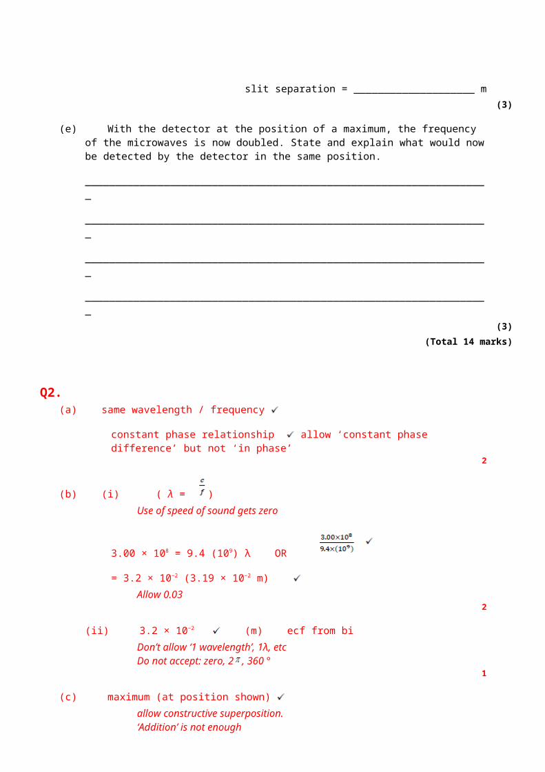
(1) (= 4.6)
highest order is 4th (1)2
[5]
Acknowledgements:
The notes in this booklet come from TES user dwyernathaniel. The original notes can be found here:https://www.tes.com/teaching-resource/a-level-physics-notes-6337841Questions from multiple areas (including progressive waves, longitudinal and transverse waves, refraction, total internal reflection) come from Bernard Rand (@BernardRand). His original resources can be found here:https://drive.google.com/drive/folders/1-2qNVLwGzJ_7AjQK9N0z4BQBIRmSHAwGQuestions in the superposition section come from the IoP TAP project. The original resources can be found here:https://spark.iop.org/episode-320-superposition#grefQuestions in the diffraction section come from the IoP TAP project. The original resources can be found here:https://spark.iop.org/episode-323-diffraction#gref