Progressive collapse behavior of rotor-type diagrid …shb.skku.edu/_res/hibs/etc/72.pdfProgressive...
16
Progressive collapse behavior of rotor-type diagrid buildings Jinkoo Kim* ,† and Jieun Kong Department of Architectural Engineering, Sungkyunkwan University, Suwon, Korea SUMMARY In this study, the progressive collapse-resisting capacities of axi-symmetric or rotor-type diagrid structural system buildings were evaluated based on arbitrary column removal scenario. For analysis models, 33-story buildings with cylindrical, convex, concave and gourd shapes were designed, and their nonlinear static and dynamic analysis results were compared. The effect of design variables such as the number of total stories, slope of diagrids and the location of removed members was also investigated. According to the analysis results, the rotor-type diagrid structures showed sufficient progressive collapse-resisting capacity regardless of the differences in shapes when a couple of diagrids were removed from the first story. The design parameter such as building height and the slope of the diagrids did not affect the results significantly as long as they were designed to meet the current design code. Copyright © 2012 John Wiley & Sons, Ltd. Received 21 October 2011; Accepted 9 December 2011 KEYWORDS: progressive collapse; diagrid; nonlinear analysis; tall buildings 1. INTRODUCTION Current trends in the design of tall buildings are driven by diverse factors such as the demand for taller height, the need for improved safety against fire and terrorist attacks and the characteristic forms that can provide distinct identity for the buildings. These requirements have led to new solutions for structural systems and form-generation techniques. Park et al. (2004) discussed a parametric design process for form generation of tall buildings based on the architectural and structural criteria. Vollers (2008) proposed a morphological scheme that enables data to be retrieved on sustainable performance of building shapes. He categorized the geometry of high-rise buildings into extruders, rotors, twisters, tordos, transformers and free shapers depending on their form-generation method. Among the high-rise building forms, rotor is a building volume created by rotating a line around a vertical axis. When the line is vertical, the volume is a cylinder. When the line is inclined, a hyperboloid results. The Tornado Tower in Doha, Qatar, is an example of a recently built hyperboloid-shaped building. A semicircle with its ends on the rotation axis when rotated results in a globe. Rotational building models can be made to bulge (a bulging rotor) or squeeze (a squeezed rotor) just by manipulating the curve that is rotated. Recently, diagrid systems are emerging as structurally efficient as well as architecturally pleasing struc- tural systems for tall buildings. The diagrid system has been applied for structural design of axi-symmetric structures such as the Swiss-Re building in London and the Tornado Tower. The diagonal members in diagrid structural systems can carry gravity loads as well as lateral forces due to their triangulated configuration in a distributive and uniform manner. Compared with conventional framed tubular structures without diagonals, diagrid structures are more effective in minimizing shear deformation because they carry shear by axial action of the diagonal members, while conventional tubular structures carry shear by the bending of the vertical columns and horizontal spandrels (Moon, 2007). Kim and Lee (2010) showed that the tube-type diagrid structure generally had high progressive collapse-resisting capacity. *Correspondence to: Jinkoo Kim, Department of Architectural Engineering, Sungkyunkwan University, 300 Cheoncheon-dong, Jangan-gu, Suwon, 440-746, Korea. † E-mail: [email protected] THE STRUCTURAL DESIGN OF TALL AND SPECIAL BUILDINGS Struct. Design Tall Spec. Build. 22, 1199–1214 (2013) Published online 8 February 2012 in Wiley Online Library (wileyonlinelibrary.com/journal/tal). DOI: 10.1002/tal.762 Copyright © 2012 John Wiley & Sons, Ltd.
Transcript of Progressive collapse behavior of rotor-type diagrid …shb.skku.edu/_res/hibs/etc/72.pdfProgressive...
THE STRUCTURAL DESIGN OF TALL AND SPECIAL BUILDINGSStruct. Design Tall Spec. Build. 22, 1199–1214 (2013)Published online 8 February 2012 in Wiley Online Library (wileyonlinelibrary.com/journal/tal). DOI: 10.1002/tal.762
Progressive collapse behavior of rotor-type diagrid buildings
Jinkoo Kim*,† and Jieun Kong
Department of Architectural Engineering, Sungkyunkwan University, Suwon, Korea
SUMMARY
In this study, the progressive collapse-resisting capacities of axi-symmetric or rotor-type diagrid structuralsystem buildings were evaluated based on arbitrary column removal scenario. For analysis models, 33-storybuildings with cylindrical, convex, concave and gourd shapes were designed, and their nonlinear static anddynamic analysis results were compared. The effect of design variables such as the number of total stories,slope of diagrids and the location of removed members was also investigated. According to the analysisresults, the rotor-type diagrid structures showed sufficient progressive collapse-resisting capacity regardlessof the differences in shapes when a couple of diagrids were removed from the first story. The designparameter such as building height and the slope of the diagrids did not affect the results significantly as longas they were designed to meet the current design code. Copyright © 2012 John Wiley & Sons, Ltd.
Received 21 October 2011; Accepted 9 December 2011
KEYWORDS: progressive collapse; diagrid; nonlinear analysis; tall buildings
1. INTRODUCTION
Current trends in the design of tall buildings are driven by diverse factors such as the demand for tallerheight, the need for improved safety against fire and terrorist attacks and the characteristic forms thatcan provide distinct identity for the buildings. These requirements have led to new solutions for structuralsystems and form-generation techniques. Park et al. (2004) discussed a parametric design process forform generation of tall buildings based on the architectural and structural criteria. Vollers (2008) proposeda morphological scheme that enables data to be retrieved on sustainable performance of building shapes.He categorized the geometry of high-rise buildings into extruders, rotors, twisters, tordos, transformersand free shapers depending on their form-generation method. Among the high-rise building forms, rotoris a building volume created by rotating a line around a vertical axis. When the line is vertical, the volumeis a cylinder. When the line is inclined, a hyperboloid results. The Tornado Tower in Doha, Qatar, is anexample of a recently built hyperboloid-shaped building. A semicircle with its ends on the rotation axiswhen rotated results in a globe. Rotational building models can be made to bulge (a bulging rotor) orsqueeze (a squeezed rotor) just by manipulating the curve that is rotated.Recently, diagrid systems are emerging as structurally efficient as well as architecturally pleasing struc-
tural systems for tall buildings. The diagrid system has been applied for structural design of axi-symmetricstructures such as the Swiss-Re building in London and the Tornado Tower. The diagonal members indiagrid structural systems can carry gravity loads as well as lateral forces due to their triangulatedconfiguration in a distributive and uniform manner. Compared with conventional framed tubularstructures without diagonals, diagrid structures aremore effective in minimizing shear deformation becausethey carry shear by axial action of the diagonal members, while conventional tubular structures carry shearby the bending of the vertical columns and horizontal spandrels (Moon, 2007). Kim and Lee (2010)showed that the tube-type diagrid structure generally had high progressive collapse-resisting capacity.
*Correspondence to: Jinkoo Kim, Department of Architectural Engineering, Sungkyunkwan University, 300Cheoncheon-dong, Jangan-gu, Suwon, 440-746, Korea.†E-mail: [email protected]
Copyright © 2012 John Wiley & Sons, Ltd.
1200 J. KIM AND J. KONG
The current trend of minimizing the number of interior and exterior columns to provide wide openinterior space and outside view results in enhanced progressive collapse potential in modern tall buildings.Shi et al. (2010) reviewed current progressive collapse analysis methods available in the literature,discussed their suitability, applicability and reliability and proposed a new method for progressivecollapse analysis of reinforced concrete frames under blast loads. Kim and Hong (2011) investigatedthe progressive collapse-resisting capacities of tilted or twisted buildings and compared theirperformances with those of regular buildings. They found that the progressive collapse potential of thetilted structures varied significantly depending on the location of the removed column and that theprogressive collapse potential of the twisted structures is not reduced significantly since they weredesigned with more structural steel to satisfy design loads and more structural elements are involved inresisting progressive collapse when a structural member is eliminated.In this study, among the various forms of tall buildings stated above, the rotor-type buildings with
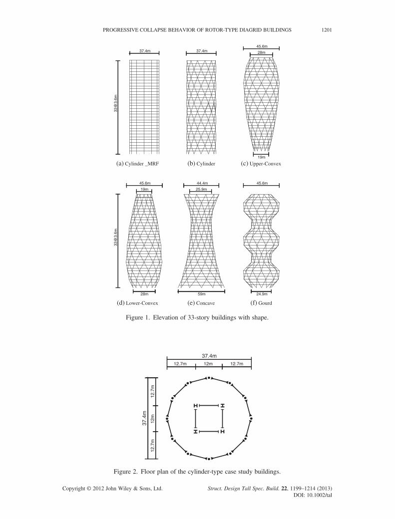
different vertical curvatures were designed using diagrid systems, and their collapse behaviors wereevaluated based on arbitrary column removal scenario. For analysis models, 33-story buildings withcylindrical, convex, concave and gourd-type elevations and circular plan shape were designed, andtheir performances were compared. The effect of design variables such as the number of total stories,slope of diagrids and the location of removed members was also investigated.
2. DESIGN AND ANALYSIS MODELING OF CASE STUDY STRUCTURES
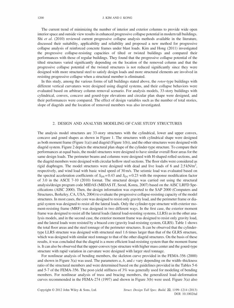
The analysis model structures are 33-story structures with the cylindrical, lower and upper convex,concave and gourd shapes as shown in Figure 1. The structures with cylindrical shape were designedas both moment frame (Figure 1(a)) and diagrid (Figure 1(b)), and the other structures were designed withdiagrid system. Figure 2 depicts the structural plan shape of the cylinder-type structure. To compare theirperformances at equal basis, the model structures were designed to have similar overall floor areas for thesame design loads. The perimeter beams and columns were designed with H-shaped rolled sections, andthe diagrid members were designed with circular hollow steel sections. The floor slabs were considered asrigid diaphragm. The model structures were designed with dead and live loads of 6 and 2.5 kN/m2,respectively, and wind load with basic wind speed of 30m/s. The seismic load was evaluated based onthe spectral acceleration coefficients of SDS= 0.43 and SD1= 0.23 with the response modification factorof 3.0 in the ASCE 7-10 (2010) format. The structural design was carried out using the structuralanalysis/design program code MIDAS (MIDAS IT, Seoul, Korea, 2007) based on the AISC LRFD Spe-cifications (AISC 2000). Then, the design information was exported to the SAP 2000 (Computers andStructures, Berkeley, CA, USA, 2004) to evaluate the progressive collapse-resisting capacity of the modelstructures. In most cases, the core was designed to resist only gravity load, and the perimeter frame or dia-grid system was designed to resist all the lateral loads. Only the cylinder-type structure with exterior mo-ment-resisting frame (MRF) was designed in two different ways. In the first case, the exterior momentframe was designed to resist all the lateral loads (lateral load-resisting systems, LLRS) as in the other ana-lysis models, and in the second case, the exterior moment frame was designed to resist only gravity load,and the lateral loads were resisted by a braced core (gravity load-resisting system, GLRS). Table 1 showsthe total floor areas and the steel tonnage of the perimeter structures. It can be observed that the cylinder-type LLRS structure was designed with structural steel 1.6 times larger than that of the GLRS structure,which was designed with similar steel tonnage to that of the other diagrid structures. On the basis of theseresults, it was concluded that the diagrid is a more efficient load-resisting system than the moment frameis. It can also be observed that the upper-convex type structure with higher mass center and the gourd-typestructure with rapid variation in curvature were designed with larger steel tonnage.For nonlinear analysis of bending members, the skeleton curve provided in the FEMA-356 (2000)
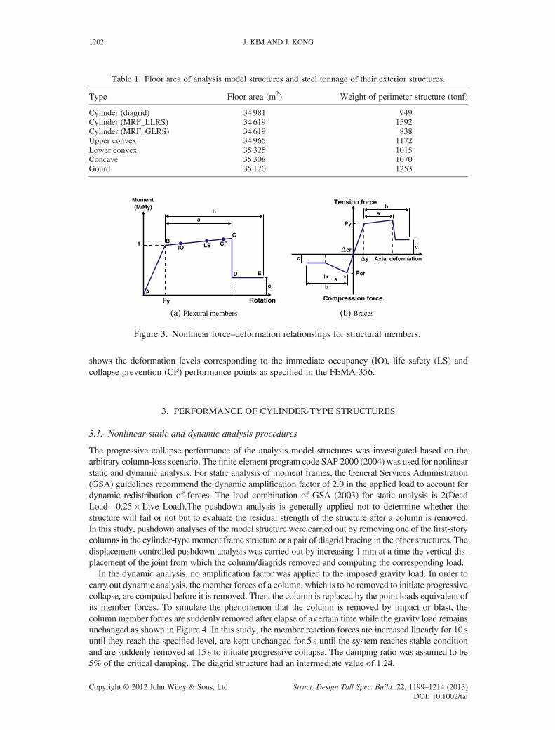
and shown in Figure 3(a) was used. The parameters a, b, and c vary depending on the width–thicknessratio of the structural members and were determined based on the guidelines provided in the Tables 5-6and 5-7 of the FEMA-356. The post-yield stiffness of 3% was generally used for modeling of bendingmembers. For nonlinear analysis of truss and bracing members, the generalized load–deformationcurves recommended in the FEMA-274 (1997) and shown in Figure 3(b) were used. Figure 3(a) also
Copyright © 2012 John Wiley & Sons, Ltd. Struct. Design Tall Spec. Build. 22, 1199–1214 (2013)DOI: 10.1002/tal
12.7m 12.7m12m
37.4m
12.7
m12
.7m
12m
37.4
m
Figure 2. Floor plan of the cylinder-type case study buildings.
37.4m
33@
3.6m
37.4m45.6m
28m
19m
(a) Cylinder _MRF (b) Cylinder (c) Upper-Convex
45.6m
19m
28m
33@
3.6m
44.4m
25.9m
59m
45.6m
24.9m
(d) Lower-Convex (e) Concave (f) Gourd
Figure 1. Elevation of 33-story buildings with shape.
PROGRESSIVE COLLAPSE BEHAVIOR OF ROTOR-TYPE DIAGRID BUILDINGS 1201
Copyright © 2012 John Wiley & Sons, Ltd. Struct. Design Tall Spec. Build. 22, 1199–1214 (2013)DOI: 10.1002/tal
Moment(M/My)
a
A
BC
IO LS CP
D E
b
c
1
y Rotation
c
ab
Pcr
Py
ba
c
y
cr
Axial deformation
Compression force
Tension force
(a) Flexural members (b) Braces
Figure 3. Nonlinear force–deformation relationships for structural members.
Table 1. Floor area of analysis model structures and steel tonnage of their exterior structures.
Type Floor area (m2) Weight of perimeter structure (tonf)
Cylinder (diagrid) 34 981 949Cylinder (MRF_LLRS) 34 619 1592Cylinder (MRF_GLRS) 34 619 838Upper convex 34 965 1172Lower convex 35 325 1015Concave 35 308 1070Gourd 35 120 1253
1202 J. KIM AND J. KONG
Copyright © 2012 John Wiley & Sons, Ltd. Struct. Design Tall Spec. Build. 22, 1199–1214 (2013DOI: 10.1002/ta
shows the deformation levels corresponding to the immediate occupancy (IO), life safety (LS) andcollapse prevention (CP) performance points as specified in the FEMA-356.
3. PERFORMANCE OF CYLINDER-TYPE STRUCTURES
3.1. Nonlinear static and dynamic analysis procedures
The progressive collapse performance of the analysis model structures was investigated based on thearbitrary column-loss scenario. The finite element program code SAP 2000 (2004) was used for nonlinearstatic and dynamic analysis. For static analysis of moment frames, the General Services Administration(GSA) guidelines recommend the dynamic amplification factor of 2.0 in the applied load to account fordynamic redistribution of forces. The load combination of GSA (2003) for static analysis is 2(DeadLoad + 0.25�Live Load).The pushdown analysis is generally applied not to determine whether thestructure will fail or not but to evaluate the residual strength of the structure after a column is removed.In this study, pushdown analyses of the model structure were carried out by removing one of the first-storycolumns in the cylinder-typemoment frame structure or a pair of diagrid bracing in the other structures. Thedisplacement-controlled pushdown analysis was carried out by increasing 1mm at a time the vertical dis-placement of the joint from which the column/diagrids removed and computing the corresponding load.In the dynamic analysis, no amplification factor was applied to the imposed gravity load. In order to
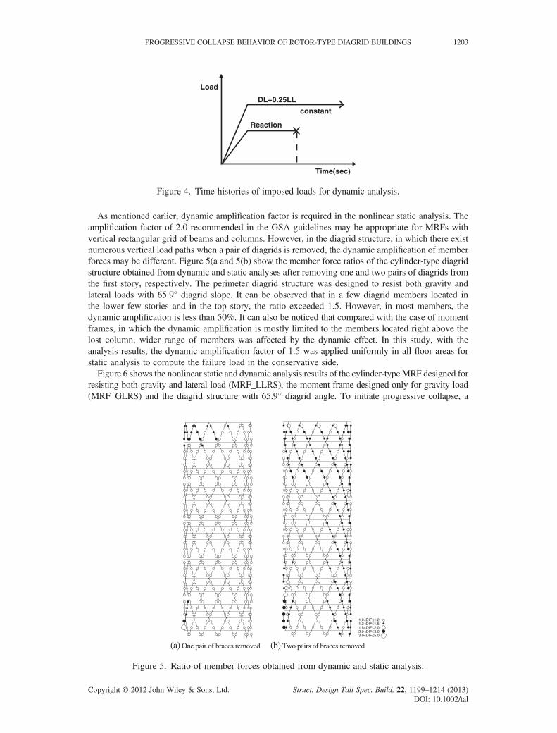
carry out dynamic analysis, the member forces of a column, which is to be removed to initiate progressivecollapse, are computed before it is removed. Then, the column is replaced by the point loads equivalent ofits member forces. To simulate the phenomenon that the column is removed by impact or blast, thecolumn member forces are suddenly removed after elapse of a certain time while the gravity load remainsunchanged as shown in Figure 4. In this study, the member reaction forces are increased linearly for 10 suntil they reach the specified level, are kept unchanged for 5 s until the system reaches stable conditionand are suddenly removed at 15 s to initiate progressive collapse. The damping ratio was assumed to be5% of the critical damping. The diagrid structure had an intermediate value of 1.24.
)l
Load
DL+0.25LL
Reaction
constant
Time(sec)
Figure 4. Time histories of imposed loads for dynamic analysis.
PROGRESSIVE COLLAPSE BEHAVIOR OF ROTOR-TYPE DIAGRID BUILDINGS 1203
As mentioned earlier, dynamic amplification factor is required in the nonlinear static analysis. Theamplification factor of 2.0 recommended in the GSA guidelines may be appropriate for MRFs withvertical rectangular grid of beams and columns. However, in the diagrid structure, in which there existnumerous vertical load paths when a pair of diagrids is removed, the dynamic amplification of memberforces may be different. Figure 5(a and 5(b) show the member force ratios of the cylinder-type diagridstructure obtained from dynamic and static analyses after removing one and two pairs of diagrids fromthe first story, respectively. The perimeter diagrid structure was designed to resist both gravity andlateral loads with 65.9� diagrid slope. It can be observed that in a few diagrid members located inthe lower few stories and in the top story, the ratio exceeded 1.5. However, in most members, thedynamic amplification is less than 50%. It can also be noticed that compared with the case of momentframes, in which the dynamic amplification is mostly limited to the members located right above thelost column, wider range of members was affected by the dynamic effect. In this study, with theanalysis results, the dynamic amplification factor of 1.5 was applied uniformly in all floor areas forstatic analysis to compute the failure load in the conservative side.Figure 6 shows the nonlinear static and dynamic analysis results of the cylinder-typeMRF designed for
resisting both gravity and lateral load (MRF_LLRS), the moment frame designed only for gravity load(MRF_GLRS) and the diagrid structure with 65.9� diagrid angle. To initiate progressive collapse, a
1.0<DIF≤1.21.2<DIF≤1.51.5<DIF≤2.02.0<DIF≤3.03.0<DIF≤5.0
(a) One pair of braces removed (b) Two pairs of braces removed
Figure 5. Ratio of member forces obtained from dynamic and static analysis.
Copyright © 2012 John Wiley & Sons, Ltd. Struct. Design Tall Spec. Build. 22, 1199–1214 (2013)DOI: 10.1002/tal

0 20 40 60 80
Displacement (cm)
0
0.5
1
1.5
2
Load
Fac
tor
MRF(LLRS)MRF(GLRS)Diagrid
0 5 10 15 20 25 30
Time (sec)
-10
-8
-6
-4
-2
0
2
Dis
plac
emen
t (cm
)
MRF(LLRS)MRF(GLRS)Diagrid
(a) Nonlinear static analysis (b) Nonlinear dynamic analysis
Figure 6. Analysis results of regular structures.
1204 J. KIM AND J. KONG
column (MRF) or a pair of diagrids was removed from the first story, and the force–vertical displacementrelationship was plotted in Figure 6(a). The vertical axis represents the load factor, which is the appliedload divided by the GSA specified load combination. It can be observed that the LLRS moment frameshowed the highest maximum load factor of 1.86 and the GLRS showed the lowest value of 0.34. Themaximum load factor of the diagrid structure turned out to be the intermediate value of 1.24. The LLRSmoment frame and the diagrid structure, which showed the maximum load factor of 1.0, may be consid-ered safe against progressive collapse triggered by the loss of a first-story column or a pair of diagrids.However, the GLRS moment frame with the maximum load factor significantly less than 1.0 is proneto fail as a result of column loss. This can be confirmed by the nonlinear dynamic analysis resultspresented in Figure 6(b). The figure shows that the vertical displacement of the GLRS structure increasedunbounded right after a first-story column was suddenly removed. It can be observed that the other twostructures remained stable. The vertical displacement of the diagrid structure was smaller than that ofthe LLRS MRF.Figure 7 shows the plastic hinge formation of the three cylinder-type model structures at their
maximum strengths. In the LLRS structure, plastic hinges formed at beam ends in nine stories abovethe lost column. The analysis stopped when plastic hinges finally formed at the second-story columns.In the GLRS structure, plastic hinges formed in all beams located at the bays from which the column
B IO LS CP C D E
(a) LLRS (b) GLRS (c) Diagrid
Figure 7. Plastic hinge formation in the cylinder-type models.
Copyright © 2012 John Wiley & Sons, Ltd. Struct. Design Tall Spec. Build. 22, 1199–1214 (2013)DOI: 10.1002/tal
PROGRESSIVE COLLAPSE BEHAVIOR OF ROTOR-TYPE DIAGRID BUILDINGS 1205
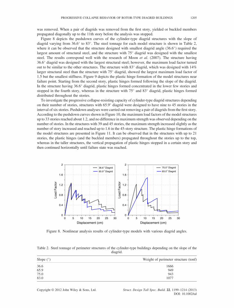
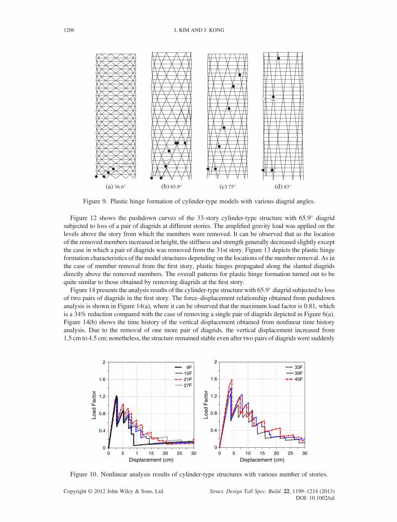
was removed. When a pair of diagrids was removed from the first story, yielded or buckled memberspropagated diagonally up to the 11th story before the analysis was stopped.Figure 8 depicts the pushdown curves of the cylinder-type diagrid structures with the slope of
diagrid varying from 36.6� to 83�. The steel tonnage for each model structure is shown in Table 2,where it can be observed that the structure designed with smallest diagrid angle (36.6�) required thelargest amount of structural steel, and the structure with 75� diagrid was designed with the smalleststeel. The results correspond well with the research of Moon et al. (2007). The structure having36.6� diagrid was designed with the largest structural steel; however, the maximum load factor turnedout to be similar to the other structures. The structure with 83� diagrid, which was designed with 14%larger structural steel than the structure with 75� diagrid, showed the largest maximum load factor of1.5 but the smallest stiffness. Figure 9 depicts the plastic hinge formation of the model structures nearfailure point. Starting from the second story, plastic hinges formed following the slope of the diagrid.In the structure having 36.6� diagrid, plastic hinges formed concentrated in the lower few stories andstopped in the fourth story, whereas in the structure with 75� and 83� diagrid, plastic hinges formeddistributed throughout the stories.To investigate the progressive collapse-resisting capacity of cylinder-type diagrid structures depending
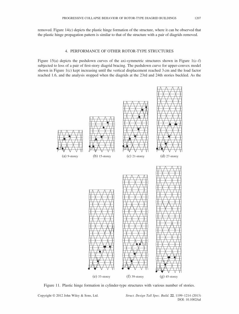
on their number of stories, structures with 65.9� diagrid were designed to have nine to 45 stories in theinterval of six stories. Pushdown analyses were carried out removing a pair of diagrids from the first story.According to the pushdown curves shown in Figure 10, the maximum load factors of the model structuresup to 33 stories reached about 1.2, and no difference inmaximum strength was observed depending on thenumber of stories. In the structures with 39 and 45 stories, the maximum strength increased slightly as thenumber of story increased and reached up to 1.6 in the 45-story structure. The plastic hinge formations ofthe model structures are presented in Figure 11. It can be observed that in the structures with up to 21stories, the plastic hinges (and the buckled members) propagated throughout the stories up to the top,whereas in the taller structures, the vertical propagation of plastic hinges stopped in a certain story andthen continued horizontally until failure state was reached.
0 5 10 15 20 25 30
Displacement (cm)
0
0.4
0.8
1.2
1.6
2
Load
Fac
tor
36.6 Diagrid
65.9 Diagrid
0 5 10 15 20 25 30
Displacement (cm)
0
0.4
0.8
1.2
1.6
2
Load
Fac
tor
75.0 Diagrid
83.0 Diagrid
Figure 8. Nonlinear analysis results of cylinder-type models with various diagrid angles.
Table 2. Steel tonnage of perimeter structures of the cylinder-type buildings depending on the slope of thediagrid.
Slope (�) Weight of perimeter structure (tonf)
36.6 166665.9 94975.0 94383.0 1077
Copyright © 2012 John Wiley & Sons, Ltd. Struct. Design Tall Spec. Build. 22, 1199–1214 (2013)DOI: 10.1002/tal
(a) 36.6° (b) 65.9° (c) 75° (d) 83°
Figure 9. Plastic hinge formation of cylinder-type models with various diagrid angles.
1206 J. KIM AND J. KONG
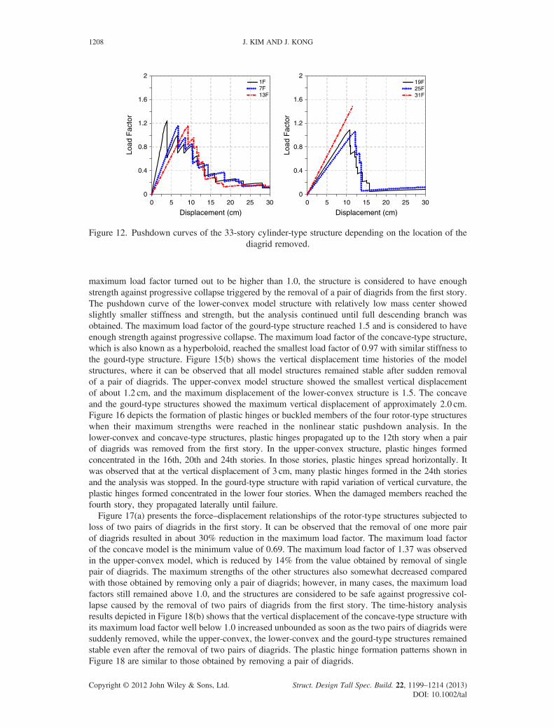
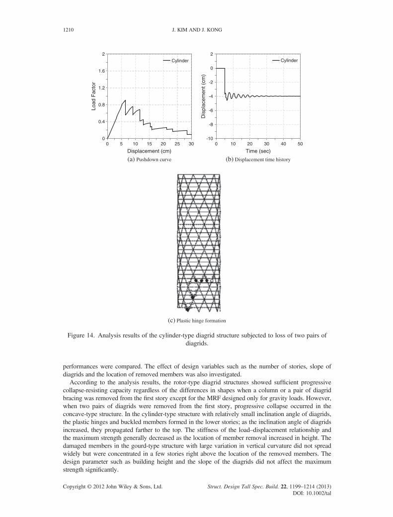
Figure 12 shows the pushdown curves of the 33-story cylinder-type structure with 65.9� diagridsubjected to loss of a pair of diagrids at different stories. The amplified gravity load was applied on thelevels above the story from which the members were removed. It can be observed that as the locationof the removedmembers increased in height, the stiffness and strength generally decreased slightly exceptthe case in which a pair of diagrids was removed from the 31st story. Figure 13 depicts the plastic hingeformation characteristics of the model structures depending on the locations of the member removal. As inthe case of member removal from the first story, plastic hinges propagated along the slanted diagridsdirectly above the removed members. The overall patterns for plastic hinge formation turned out to bequite similar to those obtained by removing diagrids at the first story.Figure 14 presents the analysis results of the cylinder-type structure with 65.9� diagrid subjected to loss
of two pairs of diagrids in the first story. The force–displacement relationship obtained from pushdownanalysis is shown in Figure 14(a), where it can be observed that the maximum load factor is 0.81, whichis a 34% reduction compared with the case of removing a single pair of diagrids depicted in Figure 6(a).Figure 14(b) shows the time history of the vertical displacement obtained from nonlinear time historyanalysis. Due to the removal of one more pair of diagrids, the vertical displacement increased from1.5 cm to 4.5 cm; nonetheless, the structure remained stable even after two pairs of diagrids were suddenly
0 5 1 15 20 25 30
Displacement (cm)
0
0.4
0.8
1.2
1.6
2
Load
Fac
tor
9F15F21F27F
0 5 10 15 20 25 30
Displacement (cm)
0
0.4
0.8
1.2
1.6
2
Load
Fac
tor
33F39F45F
Figure 10. Nonlinear analysis results of cylinder-type structures with various number of stories.
Copyright © 2012 John Wiley & Sons, Ltd. Struct. Design Tall Spec. Build. 22, 1199–1214 (2013)DOI: 10.1002/tal
PROGRESSIVE COLLAPSE BEHAVIOR OF ROTOR-TYPE DIAGRID BUILDINGS 1207
removed. Figure 14(c) depicts the plastic hinge formation of the structure, where it can be observed thatthe plastic hinge propagation pattern is similar to that of the structure with a pair of diagrids removed.
4. PERFORMANCE OF OTHER ROTOR-TYPE STRUCTURES
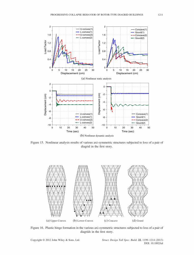
Figure 15(a) depicts the pushdown curves of the axi-symmetric structures shown in Figure 1(c–f)subjected to loss of a pair of first-story diagrid bracing. The pushdown curve for upper-convex modelshown in Figure 1(c) kept increasing until the vertical displacement reached 3 cm and the load factorreached 1.6, and the analysis stopped when the diagrids at the 23rd and 24th stories buckled. As the
(a) 9-storey (b) 15-storey (c) 21-storey (d) 27-storey
(e) 33-storey (f) 39-storey (g) 45-storey
Figure 11. Plastic hinge formation in cylinder-type structures with various number of stories.
Copyright © 2012 John Wiley & Sons, Ltd. Struct. Design Tall Spec. Build. 22, 1199–1214 (2013)DOI: 10.1002/tal
0 5 10 15 20 25 30
Displacement (cm)
0
0.4
0.8
1.2
1.6
2
Load
Fac
tor
1F7F13F
0 5 10 15 20 25 30
Displacement (cm)
0
0.4
0.8
1.2
1.6
2
Load
Fac
tor
19F25F31F
Figure 12. Pushdown curves of the 33-story cylinder-type structure depending on the location of thediagrid removed.
1208 J. KIM AND J. KONG
maximum load factor turned out to be higher than 1.0, the structure is considered to have enoughstrength against progressive collapse triggered by the removal of a pair of diagrids from the first story.The pushdown curve of the lower-convex model structure with relatively low mass center showedslightly smaller stiffness and strength, but the analysis continued until full descending branch wasobtained. The maximum load factor of the gourd-type structure reached 1.5 and is considered to haveenough strength against progressive collapse. The maximum load factor of the concave-type structure,which is also known as a hyperboloid, reached the smallest load factor of 0.97 with similar stiffness tothe gourd-type structure. Figure 15(b) shows the vertical displacement time histories of the modelstructures, where it can be observed that all model structures remained stable after sudden removalof a pair of diagrids. The upper-convex model structure showed the smallest vertical displacementof about 1.2 cm, and the maximum displacement of the lower-convex structure is 1.5. The concaveand the gourd-type structures showed the maximum vertical displacement of approximately 2.0 cm.Figure 16 depicts the formation of plastic hinges or buckled members of the four rotor-type structureswhen their maximum strengths were reached in the nonlinear static pushdown analysis. In thelower-convex and concave-type structures, plastic hinges propagated up to the 12th story when a pairof diagrids was removed from the first story. In the upper-convex structure, plastic hinges formedconcentrated in the 16th, 20th and 24th stories. In those stories, plastic hinges spread horizontally. Itwas observed that at the vertical displacement of 3 cm, many plastic hinges formed in the 24th storiesand the analysis was stopped. In the gourd-type structure with rapid variation of vertical curvature, theplastic hinges formed concentrated in the lower four stories. When the damaged members reached thefourth story, they propagated laterally until failure.Figure 17(a) presents the force–displacement relationships of the rotor-type structures subjected to
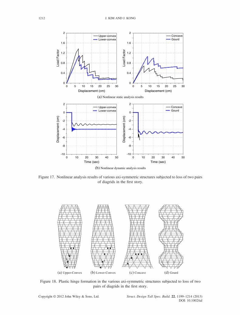
loss of two pairs of diagrids in the first story. It can be observed that the removal of one more pairof diagrids resulted in about 30% reduction in the maximum load factor. The maximum load factorof the concave model is the minimum value of 0.69. The maximum load factor of 1.37 was observedin the upper-convex model, which is reduced by 14% from the value obtained by removal of singlepair of diagrids. The maximum strengths of the other structures also somewhat decreased comparedwith those obtained by removing only a pair of diagrids; however, in many cases, the maximum loadfactors still remained above 1.0, and the structures are considered to be safe against progressive col-lapse caused by the removal of two pairs of diagrids from the first story. The time-history analysisresults depicted in Figure 18(b) shows that the vertical displacement of the concave-type structure withits maximum load factor well below 1.0 increased unbounded as soon as the two pairs of diagrids weresuddenly removed, while the upper-convex, the lower-convex and the gourd-type structures remainedstable even after the removal of two pairs of diagrids. The plastic hinge formation patterns shown inFigure 18 are similar to those obtained by removing a pair of diagrids.
Copyright © 2012 John Wiley & Sons, Ltd. Struct. Design Tall Spec. Build. 22, 1199–1214 (2013)DOI: 10.1002/tal
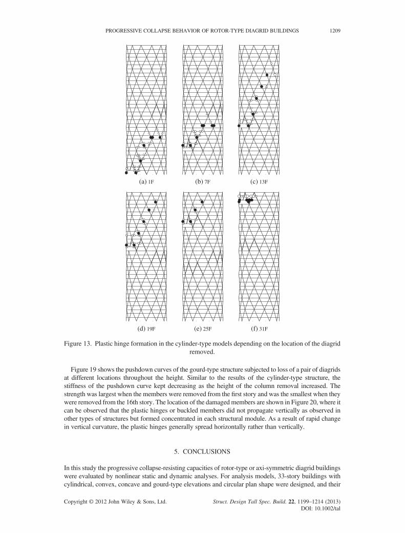
(a) 1F (b) 7F (c) 13F
(d) 19F (e) 25F (f) 31F
Figure 13. Plastic hinge formation in the cylinder-type models depending on the location of the diagridremoved.
PROGRESSIVE COLLAPSE BEHAVIOR OF ROTOR-TYPE DIAGRID BUILDINGS 1209
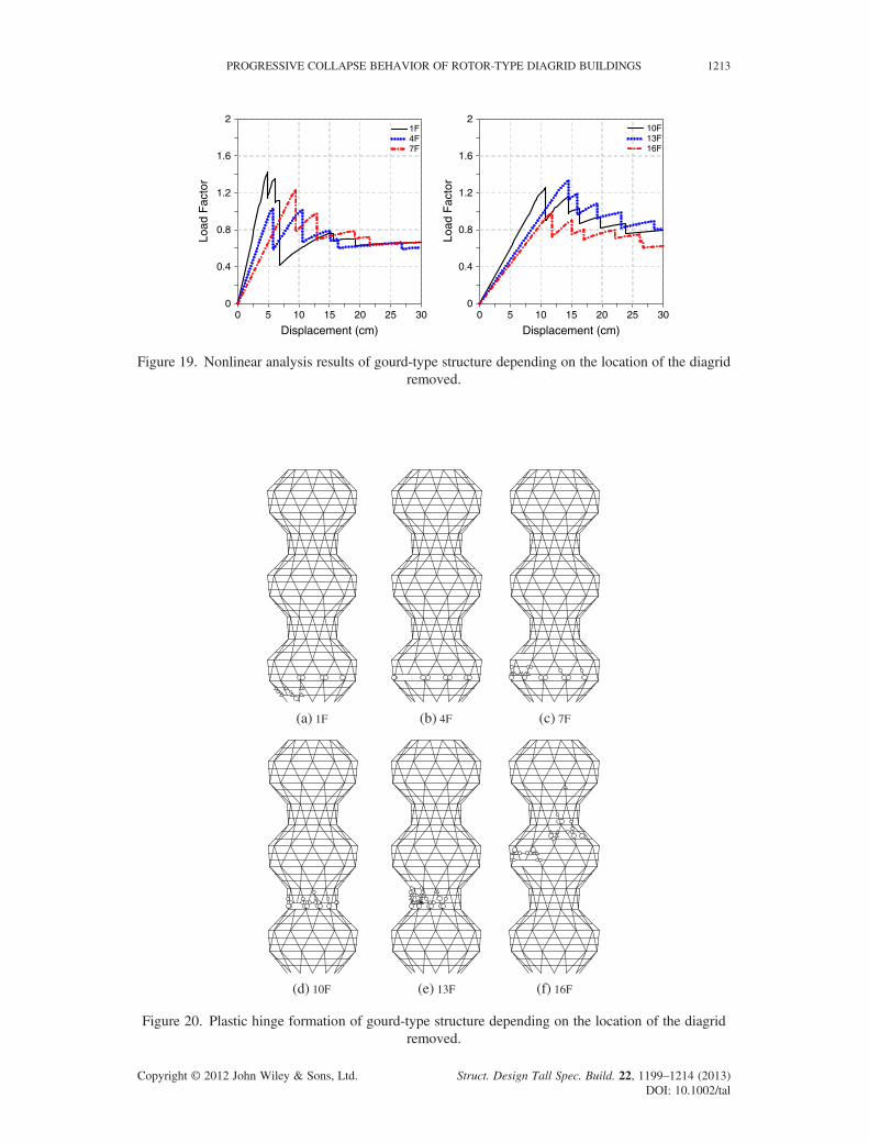
Figure 19 shows the pushdown curves of the gourd-type structure subjected to loss of a pair of diagridsat different locations throughout the height. Similar to the results of the cylinder-type structure, thestiffness of the pushdown curve kept decreasing as the height of the column removal increased. Thestrength was largest when the members were removed from the first story and was the smallest when theywere removed from the 16th story. The location of the damagedmembers are shown in Figure 20, where itcan be observed that the plastic hinges or buckled members did not propagate vertically as observed inother types of structures but formed concentrated in each structural module. As a result of rapid changein vertical curvature, the plastic hinges generally spread horizontally rather than vertically.
5. CONCLUSIONS
In this study the progressive collapse-resisting capacities of rotor-type or axi-symmetric diagrid buildingswere evaluated by nonlinear static and dynamic analyses. For analysis models, 33-story buildings withcylindrical, convex, concave and gourd-type elevations and circular plan shape were designed, and their
Copyright © 2012 John Wiley & Sons, Ltd. Struct. Design Tall Spec. Build. 22, 1199–1214 (2013)DOI: 10.1002/tal
0 5 10 15 20 25 30
Displacement (cm)
0
0.4
0.8
1.2
1.6
2
Load
Fac
tor
Cylinder
0 10 20 30 40 50
Time (sec)
-10
-8
-6
-4
-2
0
2
Dis
plac
emen
t (cm
)
Cylinder
(a) Pushdown curve (b) Displacement time history
(c) Plastic hinge formation
Figure 14. Analysis results of the cylinder-type diagrid structure subjected to loss of two pairs ofdiagrids.
1210 J. KIM AND J. KONG
performances were compared. The effect of design variables such as the number of stories, slope ofdiagrids and the location of removed members was also investigated.According to the analysis results, the rotor-type diagrid structures showed sufficient progressive
collapse-resisting capacity regardless of the differences in shapes when a column or a pair of diagridbracing was removed from the first story except for the MRF designed only for gravity loads. However,when two pairs of diagrids were removed from the first story, progressive collapse occurred in theconcave-type structure. In the cylinder-type structure with relatively small inclination angle of diagrids,the plastic hinges and buckled members formed in the lower stories; as the inclination angle of diagridsincreased, they propagated farther to the top. The stiffness of the load–displacement relationship andthe maximum strength generally decreased as the location of member removal increased in height. Thedamaged members in the gourd-type structure with large variation in vertical curvature did not spreadwidely but were concentrated in a few stories right above the location of the removed members. Thedesign parameter such as building height and the slope of the diagrids did not affect the maximumstrength significantly.
Copyright © 2012 John Wiley & Sons, Ltd. Struct. Design Tall Spec. Build. 22, 1199–1214 (2013)DOI: 10.1002/tal
0 5 10 15 20 25 30 0 5 10 15 20 25 30
Displacement (cm)
0
0.4
0.8
1.2
1.6
2
0
0.4
0.8
1.2
1.6
2
Load
Fac
tor
U-convex(1)L-convex(1)U-convex(2)L-convex(2)
Displacement (cm)
Load
Fac
tor
Concave(1)Gourd(1)Concave(2)Gourd(2)
(a) Nonlinear static analysis
0 10 20 30 40 50
Time (sec)
-10
-8
-6
-4
-2
0
2
Dis
plac
emen
t (cm
)
U-convex(1)L-convex(1)U-convex(2)L-convex(2)
0 10 20 30 40 50
Time (sec)
-10
-8
-6
-4
-2
0
Dis
plac
emen
t (cm
)
Concave(1)Gourd(1)Concave(2)Gourd(2)
(b) Nonlinear dynamic analysis
Figure 15. Nonlinear analysis results of various axi-symmetric structures subjected to loss of a pair ofdiagrid in the first story.
(a) Upper-Convex (b) Lower-Convex (c) Concave (d) Gourd
Figure 16. Plastic hinge formation in the various axi-symmetric structures subjected to loss of a pair ofdiagrids in the first story.
PROGRESSIVE COLLAPSE BEHAVIOR OF ROTOR-TYPE DIAGRID BUILDINGS 1211
Copyright © 2012 John Wiley & Sons, Ltd. Struct. Design Tall Spec. Build. 22, 1199–1214 (2013)DOI: 10.1002/tal
0 5 10 15 20 25 30
Displacement (cm)
0
0.4
0.8
1.2
1.6
2
Load
Fac
tor
Upper-convexLower-convex
0 5 10 15 20 25 30
Displacement (cm)
0
0.4
0.8
1.2
1.6
2
Load
Fac
tor
ConcaveGourd
(a) Nonlinear static analysis results
0 10 20 30 40 50
Time (sec)
-10
-8
-6
-4
-2
0
2
Dis
plac
emen
t (cm
)
Upper-convexLower-convex
0 10 20 30 40 50
Time (sec)
-10
-8
-6
-4
-2
0
2
Dis
plac
emen
t (cm
)
ConcaveGourd
(b) Nonlinear dynamic analysis results
Figure 17. Nonlinear analysis results of various axi-symmetric structures subjected to loss of two pairsof diagrids in the first story.
(a) Upper-Convex (b) Lower-Convex (c) Concave (d) Gourd
Figure 18. Plastic hinge formation in the various axi-symmetric structures subjected to loss of twopairs of diagrids in the first story.
1212 J. KIM AND J. KONG
Copyright © 2012 John Wiley & Sons, Ltd. Struct. Design Tall Spec. Build. 22, 1199–1214 (2013)DOI: 10.1002/tal
0 5 10 15 20 25 30
Displacement (cm)
0
0.4
0.8
1.2
1.6
2
Load
Fac
tor
1F4F7F
0 5 10 15 20 25 30
Displacement (cm)
0
0.4
0.8
1.2
1.6
2
Load
Fac
tor
10F13F16F
Figure 19. Nonlinear analysis results of gourd-type structure depending on the location of the diagridremoved.
(a) 1F (b) 4F (c) 7F
(d) 10F (e) 13F (f) 16F
Figure 20. Plastic hinge formation of gourd-type structure depending on the location of the diagridremoved.
PROGRESSIVE COLLAPSE BEHAVIOR OF ROTOR-TYPE DIAGRID BUILDINGS 1213
Copyright © 2012 John Wiley & Sons, Ltd. Struct. Design Tall Spec. Build. 22, 1199–1214 (2013)DOI: 10.1002/tal
1214 J. KIM AND J. KONG
ACKNOWLEDGEMENT
This research was supported by a grant (code # ’09 R&DA01) funded by the Ministry of Land, Transportand Maritime Affairs of the Korean government.
REFERENCES
AISC. 2000. Load and Resistance Factor Design Specification for Structural Steel Buildings. American Institute of SteelConstruction: Chicago.
ASCE 7-10. 2010.Minimum Design Loads for Buildings and Other Structures. American Society of Civil Engineers: New York.FEMA. 1997. NEHRP Commentary on the Guidelines for the Seismic Rehabilitation of Buildings, FEMA 274. Federal
Emergency Management Agency: Washington, DC.FEMA. 2000. Prestandard and Commentary for the Seismic Rehabilitation of Buildings, FEMA-356. Federal Emergency
Management Agency: Washington, DC.GSA. 2003. Progressive Collapse Analysis and Design Guidelines for New Federal Office Buildings and Major Modernization
Projects. The U.S. General Services Administration.Kim J, Hong S. 2011. Progressive collapse performance of irregular buildings. The Structural Design of Tall and Special
Buildings 20(6): 721–734.Kim J, Lee Y. 2010. Seismic Performance Evaluation of Diagrid System Buildings. The Structural Design of Tall and Special
Buildings 19(7): 761–777.MIDAS GenW. 2007. General Structure Design System for Windows. MIDAS Information Technology Co Ltd: Seoul, Korea.Moon K, Connor JJ, Fernandez JE. 2007. Diagrid structural systems for tall buildings: characteristics and methodology for
preliminary design. The Structural Design of Tall and Special Buildings 16(2).Moon KS. 2007. Diagrid Sturctural systems for tall buildings, characteristics and methodology for preliminary design. The
Structural Design of Tall and Special Buildings 16: 205–230.Park S, Elnimeiri M, Sharpe DC, Krawczyk RJ. 2004. Tall building form generation by parametric design process. CTBUH
Conference, Seoul, Korea.SAP 2000. 2004. Structural Analysis Program. Computers and Structures: Berkeley.Shi Y, Li ZX, Hao H. 2010. Methods for progressive collapse analysis of building structures under blast and impact loads.
Engineering Structures 32(6): 1691–1703.Vollers K. 2008. Morphological scheme of second-generation non-orthogonal high-rises, CTBUH 8th World Congress.
AUTHORS’ BIOGRAPHIES
Jinkoo Kim received his BS degree from Seoul National University, Korea. He received his MS andPhD degrees from the Department of Civil and Environmental Engineering, Massachusetts Institute ofTechnology. His research interests include performance evaluation and retrofit of building structuresagainst earthquake loads and progressive collapse.
Jieun Kong received her BS degree from Sungkyunkwan University, Korea. Currently, she is agraduate student in the same university.
Copyright © 2012 John Wiley & Sons, Ltd. Struct. Design Tall Spec. Build. 22, 1199–1214 (2013)DOI: 10.1002/tal