Progress Toward Achieving Full-time Lidar Winds from Geostationary Orbit C.J. Grund, J.H. Eraker, B....
20
Progress Toward Achieving Full- time Lidar Winds from Geostationary Orbit C.J. Grund, J.H. Eraker, B. Donley, and M. Stephens Ball Aerospace & Technologies Corp. (BATC), [email protected] 1600 Commerce St. Boulder, CO 80303 Working Group on Space-based Lidar Winds Ft. Walton Beach, FL February 3, 2010 Agility to Innovate, Strength to Deliver Ball Aerospace & Technologies Corp.
-
Upload
erik-watkins -
Category
Documents
-
view
219 -
download
0
Transcript of Progress Toward Achieving Full-time Lidar Winds from Geostationary Orbit C.J. Grund, J.H. Eraker, B....
Progress Toward Achieving Full-time Lidar Winds from Geostationary Orbit
C.J. Grund, J.H. Eraker, B. Donley, and M. StephensBall Aerospace & Technologies Corp. (BATC), [email protected]
1600 Commerce St. Boulder, CO 80303
Working Group on Space-based Lidar WindsFt. Walton Beach, FL
February 3, 2010
Agility to Innovate, Strength to Deliver
Ball Aerospace & Technologies Corp.
Page_2Page_2
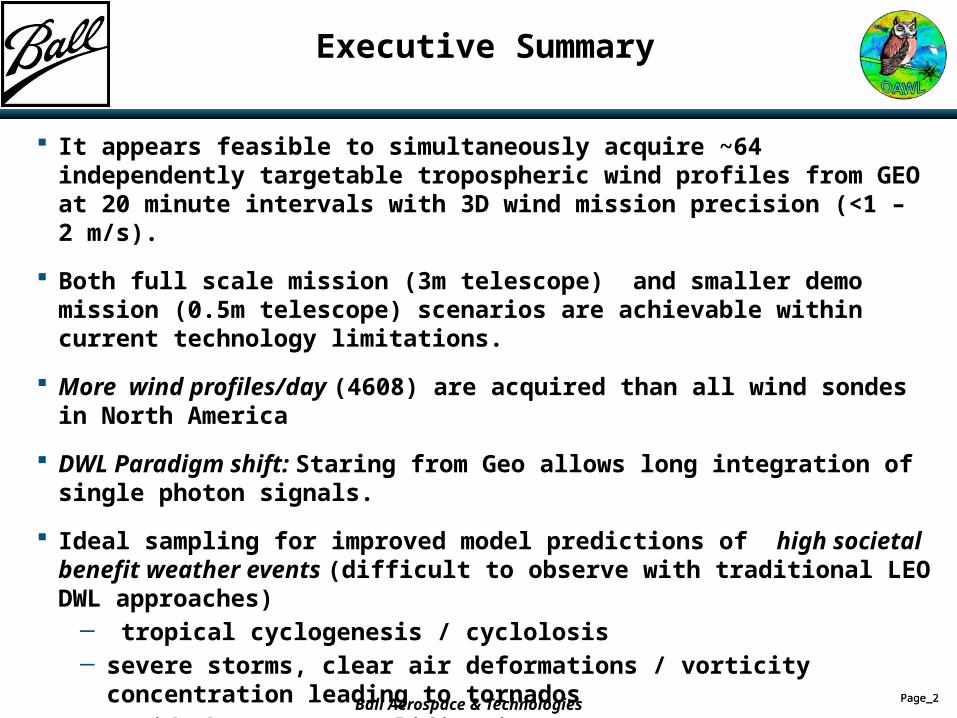
It appears feasible to simultaneously acquire ~64 independently targetable tropospheric wind profiles from GEO at 20 minute intervals with 3D wind mission precision (<1 – 2 m/s).
Both full scale mission (3m telescope) and smaller demo mission (0.5m telescope) scenarios are achievable within current technology limitations.
More wind profiles/day (4608) are acquired than all wind sondes in North America
DWL Paradigm shift: Staring from Geo allows long integration of single photon signals.
Ideal sampling for improved model predictions of high societal benefit weather events (difficult to observe with traditional LEO DWL approaches)
─ tropical cyclogenesis / cyclolosis─ severe storms, clear air deformations / vorticity concentration leading to tornados─ Rapid short wave amplification
Significant investments in needed technologies are already being made by NASA and Ball., (e.g. OAWL, ESFL, I2PC). More is need to fully develop this capability, but the payoff is high.
Executive Summary
Ball Aerospace & Technologies

Page_3Page_3
Why Winds from GEO? Isn’t LEO Hard Enough?
GEO: regional, 24/7 vantage ideal for observations of high societal benefit weather events difficult to observe from LEO:
─ Nowcasting and short term (6-36 hr) model predictions of severe stormsrapid flow deformation/ vorticity concentrationlower false alarmsgeographically pin point tornado touchdown areas
─ High temporal/spatial density tropical cyclogenesis / cyclolosis observations rapid updates in critical steering / sheer regions improved hurricane landfall and intensity model prediction
─ Tracking rapidly evolving short waves─ Supporting eddy flux measurements, regional pollution transport, night jets─ Dwells to improve short/long range forecast uncertainty─ Supporting wind farm power generation─ Does not need hydrometeors to trace flow Clear air streamline curvature
Ball Aerospace & Technologies
Page_4Page_4
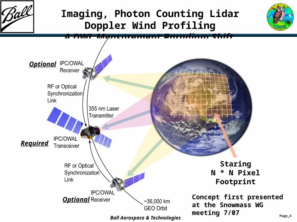
Imaging, Photon Counting Lidar Doppler Wind ProfilingA DWL Measurement Paradigm Shift
StaringN * N Pixel Footprint
Optional
Optional
Ball Aerospace & Technologies
Required
Concept first presented at the Snowmass WG meeting 7/07
Page_5Page_5
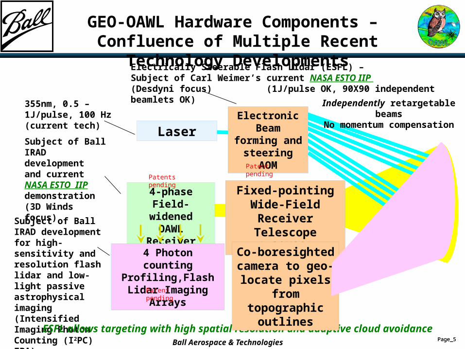
GEO-OAWL Hardware Components – Confluence of Multiple Recent Technology Developments
4-phaseField-widened
OAWL Receiver
4 Photon counting Profiling,Flash Lidar
Imaging Arrays
Subject of Ball IRAD developmentand current NASA ESTO IIP demonstration(3D Winds focus)
Subject of Ball IRAD developmentfor high-sensitivity and resolution flash lidar and low- light passive astrophysical imaging (Intensified Imaging Photon Counting (I2PC) FPA).
Fixed-pointingWide-FieldReceiver
Telescope (~3°X3°)
Electronic Beam forming and steering
AOM
Laser
Electrically Steerable Flash Lidar (ESFL) – Subject of Carl Weimer’s current NASA ESTO IIP (Desdyni focus) (1J/pulse OK, 90X90 independent beamlets OK)
355nm, 0.5 – 1J/pulse, 100 Hz (current tech)
ESFL allows targeting with high spatial resolution and adaptive cloud avoidance
Independently retargetable beamsNo momentum compensation
Co-boresightedcamera to geo-
locate pixels from topographic
outlines
Patent pending
Patents pending
Patent pending
Ball Aerospace & Technologies
Page_6Page_6
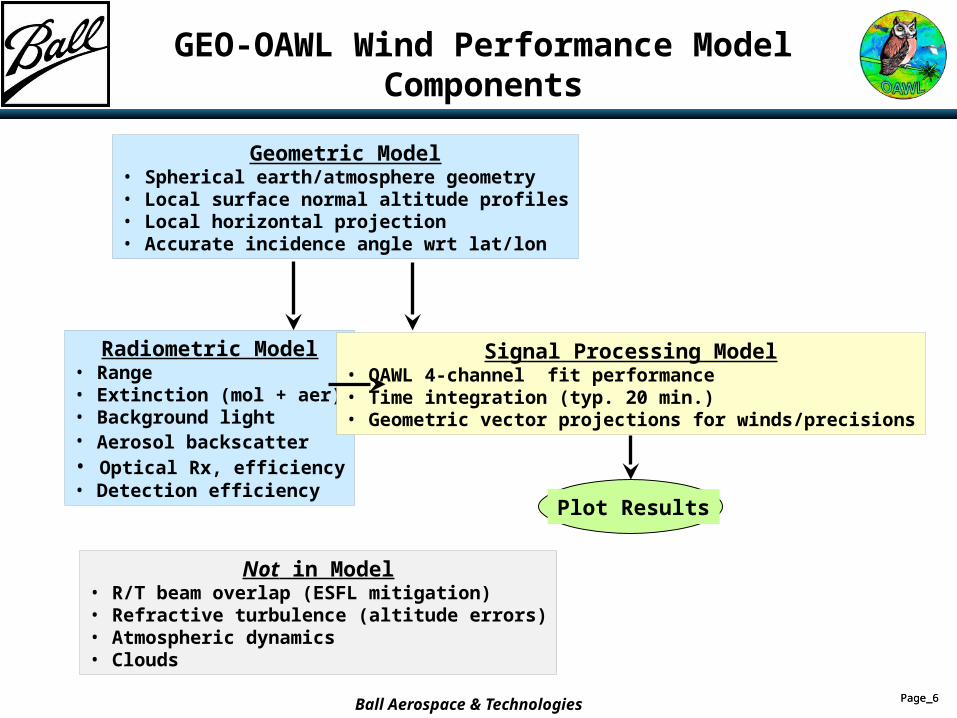
GEO-OAWL Wind Performance Model Components
Radiometric Model• Range• Extinction (mol + aer)• Background light• Aerosol backscatter • Optical Rx, efficiency• Detection efficiency
Geometric Model• Spherical earth/atmosphere geometry• Local surface normal altitude profiles• Local horizontal projection• Accurate incidence angle wrt lat/lon
Signal Processing Model• OAWL 4-channel fit performance• Time integration (typ. 20 min.)• Geometric vector projections for winds/precisions
Plot Results
Not in Model• R/T beam overlap (ESFL mitigation)• Refractive turbulence (altitude errors)• Atmospheric dynamics• Clouds
Ball Aerospace & Technologies
Page_7Page_7
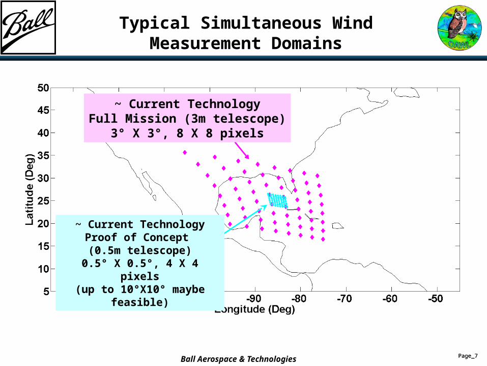
Typical Simultaneous Wind Measurement Domains
~ Current TechnologyFull Mission (3m telescope)
3° X 3°, 8 X 8 pixels
~ Current TechnologyProof of Concept (0.5m telescope)
0.5° X 0.5°, 4 X 4 pixels(up to 10°X10° maybe feasible)
Ball Aerospace & Technologies
Page_8Page_8
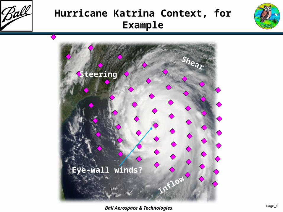
Hurricane Katrina Context, for Example
Eye-wall winds?
Inflow
ShearSteering
Ball Aerospace & Technologies
Page_9Page_9
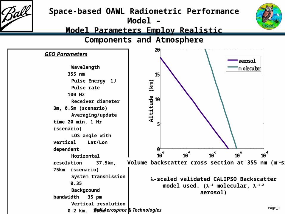
Space-based OAWL Radiometric Performance Model –Model Parameters Employ Realistic Components and Atmosphere
GEO Parameters
Wavelength
355 nm
Pulse Energy 1J
Pulse rate
100 Hz
Receiver diameter
3m, 0.5m
(scenario)
Averaging/update time
20 min, 1 Hr
(scenario)
LOS angle with vertical
Lat/Lon dependent
Horizontal resolution
37.5km, 75km
(scenario)
System transmission
0.35
Background bandwidth
35 pm
Vertical resolution
0-2 km, 250m
2-12
km, 1km
12-20
km, 2 km
Phenomenology
CALIPSO model
(right)
Wind backscatter
aerosol only
Extinction
aerosol +
molecular
l-scaled validated CALIPSO Backscatter model used. (l-4 molecular, l-1.2 aerosol)
Ball Aerospace & Technologies
10-8
10-7
10-6
10-5
10-4
0
5
10
15
20
backscatter coefficient at 355 nm m-1 sr-1
Alti
tude
, km
aerosol
molecular
Volume backscatter cross section at 355 nm (m-1sr-1)
Alt
itu
de
(km
)
Page_10Page_10
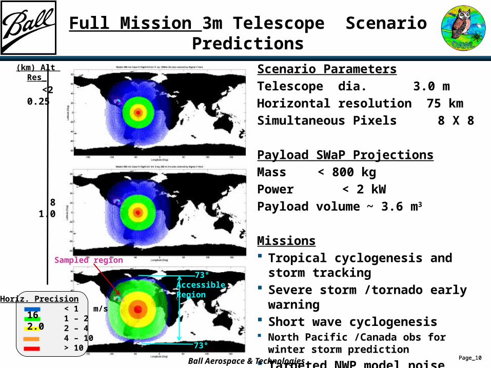
Full Mission 3m Telescope Scenario Predictions
Horiz. Precision < 1 m/s 1 – 2 2 – 4 4 – 10 > 10
(km) Alt Res_
<2 0.25
8 1.0
16 2.0Sampled region
Accessible Region
73°
73°
Scenario ParametersTelescope dia. 3.0 mHorizontal resolution 75 kmSimultaneous Pixels 8 X 8
Payload SWaP ProjectionsMass < 800 kgPower < 2 kWPayload volume ~ 3.6 m3
Missions Tropical cyclogenesis and storm tracking Severe storm /tornado early warning Short wave cyclogenesis North Pacific /Canada obs for winter storm prediction
Targeted NWP model noise reduction Targeted wind farm power prediction
Ball Aerospace & Technologies
Page_11Page_11
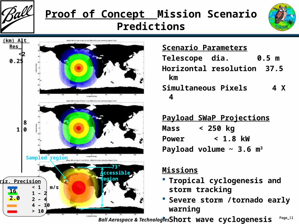
Proof of Concept Mission Scenario Predictions
Horiz. Precision < 1 m/s 1 – 2 2 – 4 4 – 10 > 10
(km) Alt Res_
<2 0.25
8 1.0
16 2.0Sampled region
Accessible Region
73°
Scenario ParametersTelescope dia. 0.5 mHorizontal resolution 37.5 kmSimultaneous Pixels 4 X 4
Payload SWaP ProjectionsMass < 250 kgPower < 1.8 kWPayload volume ~ 3.6 m3
Missions Tropical cyclogenesis and storm tracking Severe storm /tornado early warning Short wave cyclogenesis Targeted NWP model noise reduction Targeted wind farm power prediction
Ball Aerospace & Technologies
Page_12Page_12
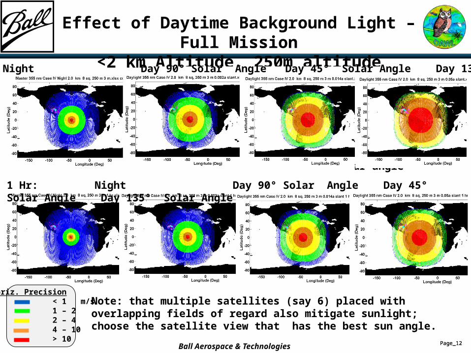
Effect of Daytime Background Light – Full Mission<2 km Altitude, 250m altitude resolution
1 Hr: Night Day 90° Solar Angle Day 45° Solar Angle Day 135° Solar Angle
45° Solar angle
20 Min: Night Day 90° Solar Angle Day 45° Solar Angle Day 135° Solar Angle
Horiz. Precision < 1 m/s 1 – 2 2 – 4 4 – 10 > 10
Note: that multiple satellites (say 6) placed with overlapping fields of regard also mitigate sunlight; choose the satellite view that has the best sun angle.
Ball Aerospace & Technologies
Page_13Page_13
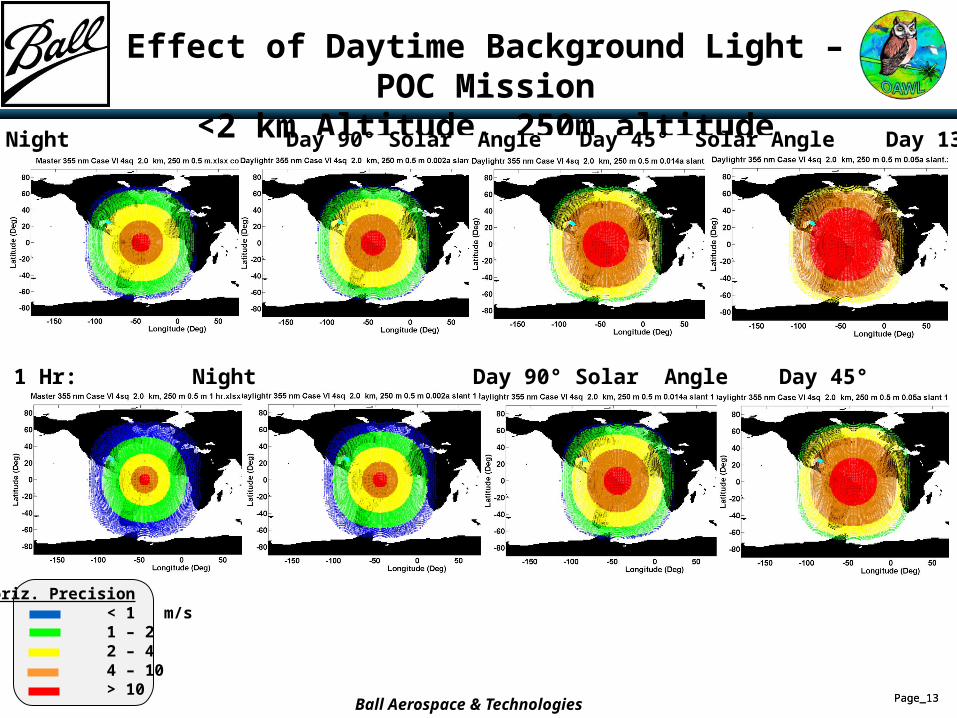
Effect of Daytime Background Light – POC Mission<2 km Altitude, 250m altitude resolution
1 Hr: Night Day 90° Solar Angle Day 45° Solar Angle Day 135° Solar Angle
20 Min: Night Day 90° Solar Angle Day 45° Solar Angle Day 135° Solar Angle
Horiz. Precision < 1 m/s 1 – 2 2 – 4 4 – 10 > 10
Ball Aerospace & Technologies
Page_14Page_14
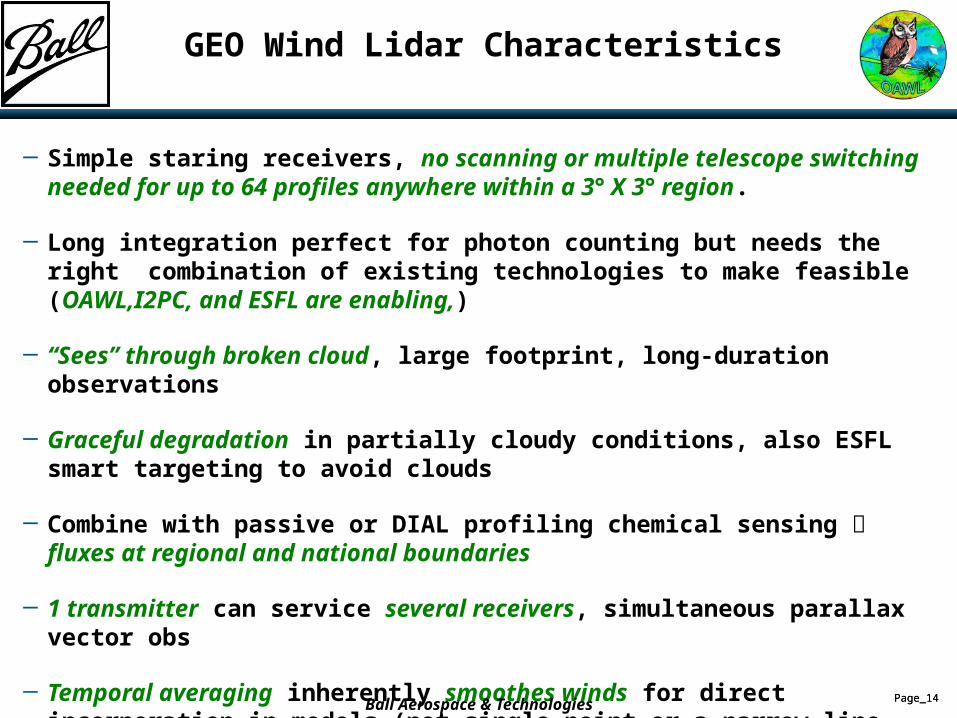
GEO Wind Lidar Characteristics
─ Simple staring receivers, no scanning or multiple telescope switching needed for up to 64 profiles anywhere within a 3° X 3° region.
─ Long integration perfect for photon counting but needs the right combination of existing technologies to make feasible (OAWL,I2PC, and ESFL are enabling,)
─ “Sees” through broken cloud, large footprint, long-duration observations
─ Graceful degradation in partially cloudy conditions, also ESFL smart targeting to avoid clouds
─ Combine with passive or DIAL profiling chemical sensing fluxes at regional and national boundaries
─ 1 transmitter can service several receivers, simultaneous parallax vector obs
─ Temporal averaging inherently smoothes winds for direct incorporation in models (not single point or a narrow line average)
─ Inherent 2-D horizontal spatial average improves wind fidelity over oceans
─ Crude pointing sufficient. Use co-boresighted camera to navigate.
─ Use of ESFL allows rapid independent retargeting of profiling pixels W/O moving telescopes
Ball Aerospace & Technologies
Page_15Page_15
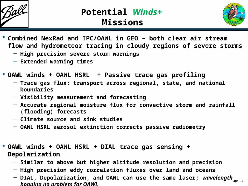
Potential Winds+ Missions
Combined NexRad and IPC/OAWL in GEO – both clear air stream flow and hydrometeor tracing in cloudy regions of severe storms
─ High precision severe storm warnings─ Extended warning times
OAWL winds + OAWL HSRL + Passive trace gas profiling─ Trace gas flux: transport across regional, state, and national boundaries─ Visibility measurement and forecasting─ Accurate regional moisture flux for convective storm and rainfall (flooding) forecasts─ Climate source and sink studies─ OAWL HSRL aerosol extinction corrects passive radiometry
OAWL winds + OAWL HSRL + DIAL trace gas sensing + Depolarization─ Similar to above but higher altitude resolution and precision─ High precision eddy correlation fluxes over land and oceans─ DIAL, Depolarization, and OAWL can use the same laser; wavelength hopping no problem for OAWL─ Cloud ice/water discrimination─ Shared large aperture telescope
Page_16Page_16
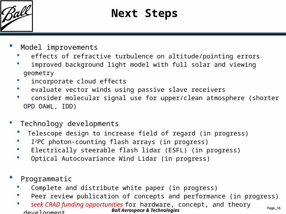
Next Steps
Model improvements effects of refractive turbulence on altitude/pointing errors improved background light model with full solar and viewing geometry incorporate cloud effects evaluate vector winds using passive slave receivers consider molecular signal use for upper/clean atmosphere (shorter OPD OAWL, IDD)
Technology developments Telescope design to increase field of regard (in progress) I2PC photon-counting flash arrays (in progress) Electrically steerable flash lidar (ESFL) (in progress) Optical Autocovariance Wind Lidar (in progress)
Programmatic Complete and distribute white paper (in progress) Peer review publication of concepts and performance (in progress) seek CRAD funding opportunities for hardware, concept, and theory development
Ball Aerospace & Technologies
Page_17Page_17
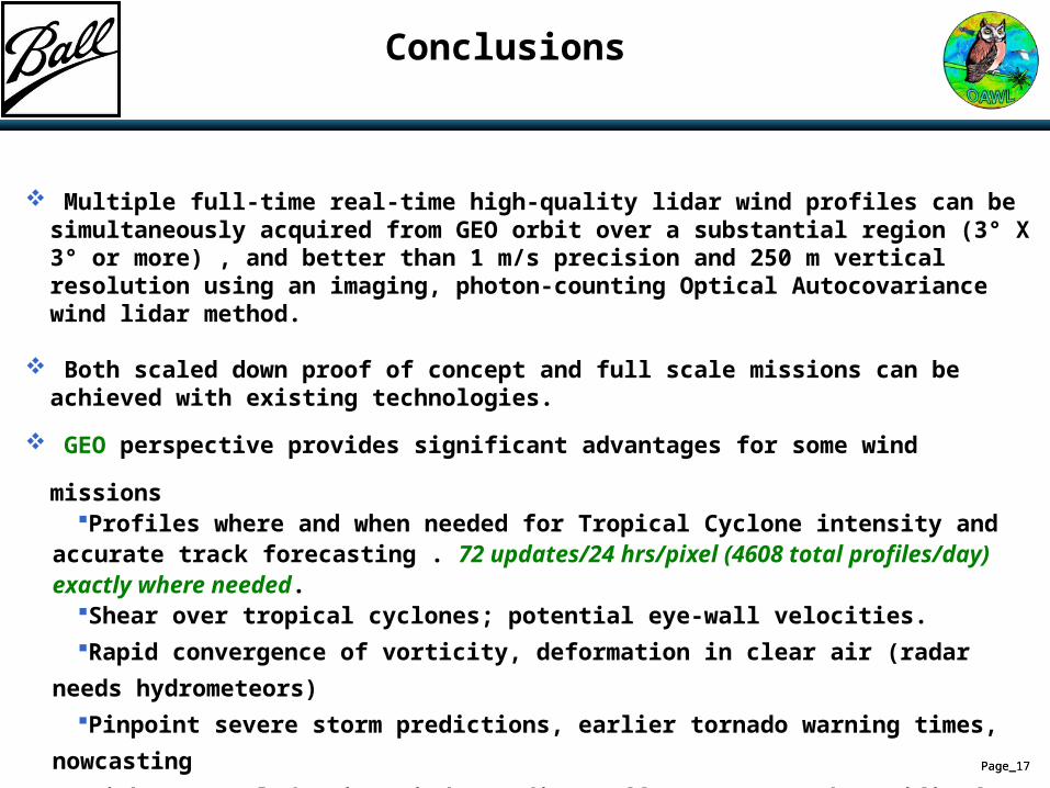
Conclusions
Multiple full-time real-time high-quality lidar wind profiles can be simultaneously acquired from GEO orbit over a substantial region (3° X 3° or more) , and better than 1 m/s precision and 250 m vertical resolution using an imaging, photon-counting Optical Autocovariance wind lidar method.
Both scaled down proof of concept and full scale missions can be achieved with existing technologies.
GEO perspective provides significant advantages for some wind missionsProfiles where and when needed for Tropical Cyclone intensity and accurate track
forecasting . 72 updates/24 hrs/pixel (4608 total profiles/day) exactly where needed. Shear over tropical cyclones; potential eye-wall velocities.Rapid convergence of vorticity, deformation in clear air (radar needs hydrometeors)Pinpoint severe storm predictions, earlier tornado warning times, nowcastingHigh temporal density wind soundings off coasts; north Pacific for example
High-efficiency electronic beam direction allows intelligent sparse/high density sampling
Modest processing requirements lead to low data rate com requirements
Page_18Page_18
Backups
Page_19Page_19
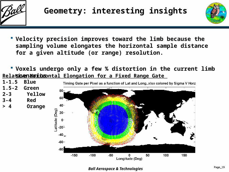
Geometry: interesting insights
Velocity precision improves toward the limb because the sampling volume elongates the horizontal sample distance for a given altitude (or range) resolution.
Voxels undergo only a few % distortion in the current limb scenarios
Relative Horizontal Elongation for a Fixed Range Gate 1-1.5 Blue1.5-2 Green 2-3 Yellow 3-4 Red> 4 Orange
Ball Aerospace & Technologies
Page_20Page_20
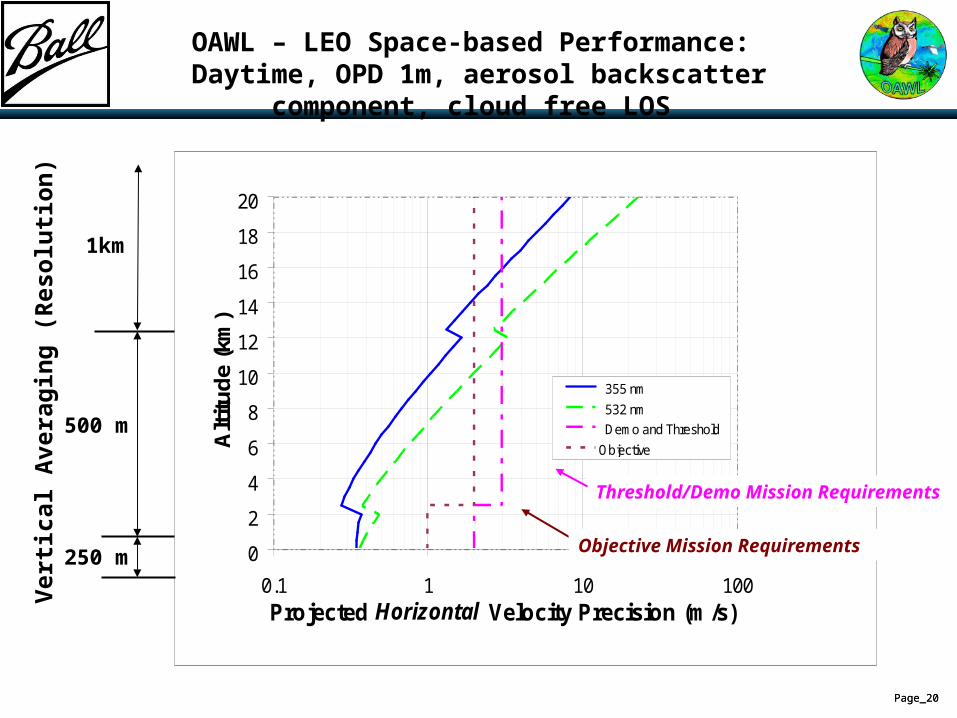
OAWL – LEO Space-based Performance: Daytime, OPD 1m, aerosol backscatter component, cloud free LOS
0
2
4
6
8
10
12
14
16
18
20
0.1 1 10 100Projected Horizontal Velocity Precision (m/s)
Alt
itu
de
(km
)
355 nm
532 nm
Demo and Threshold
Objective
Threshold/Demo Mission Requirements
250 m
500 m
1km
Ver
tica
l Ave
rag
ing
(R
eso
luti
on
)
Objective Mission Requirements