PROGRESS IN OPEN ROTOR RESEARCH: A U.S ... B2 Forward, Aft rotor blade counts BPF Blade Passing...
14
1 This material is declared a work of the U.S. Government and is not subject to copyright protection in the United States. Approved for public release; distribution is unlimited. Proceedings of ASME Turbo Expo 2015: Turbine Technical Conference and Exposition GT2015 June 15 – 19, 2015, Montréal, Canada GT2015-42203 PROGRESS IN OPEN ROTOR RESEARCH: A U.S. PERSPECTIVE Dale E. Van Zante NASA Glenn Research Center Cleveland, OH, USA ABSTRACT In response to the 1970s oil crisis, NASA created the Advanced Turboprop Project (ATP) to mature technologies for high-speed propellers to enable large reductions in fuel burn relative to turbofan engines of that era. Both single rotation and contra- rotation concepts were designed and tested in ground based facilities as well as flight. Some novel concepts/configurations were proposed as part of the effort. The high-speed propeller concepts did provide fuel burn savings, albeit with some acoustics and structural challenges to overcome. When fuel prices fell, the business case for radical new engine configurations collapsed and the research emphasis returned to high bypass ducted configurations. With rising oil prices and increased environmental concerns there is renewed interest in high-speed propeller based engine architectures. Contemporary analysis tools for aerodynamics and aeroacoustics have enabled a new era of blade designs that have both high efficiency and lower noise characteristics. A recent series of tests in the U.S. have characterized the aerodynamic performance and noise from these modern contra-rotating propeller designs. Additionally the installation and noise shielding aspects for conventional airframes and blended wing bodies have been studied. Historical estimates of ‘propfan’ performance have relied on legacy propeller performance and acoustics data. Current system studies make use of the modern propeller data and higher fidelity installation effects data to estimate the performance of a contemporary aircraft system. Contemporary designs have demonstrated high net efficiency, ~86%, at 0.78 Mach, and low noise, >15 EPNdB cumulative margin to Chapter 4 when analyzed on a NASA derived aircraft/mission. This paper presents the current state of high-speed propeller/open rotor research within the U.S. from an overall viewpoint of the various efforts ongoing. The remaining technical challenges to a production engine include propulsion airframe integration, acoustic sensitivity to aircraft weight and certification issues. NOMENCLATURE A Forward rotor annular area AoA Angle of Attack ATP Advanced Turboprop Project B1, B2 Forward, Aft rotor blade counts BPF Blade Passing Frequency CR Contra-rotating D Forward rotor diameter EASA European Aviation Safety Agency F Blade force, Eqn. 1 F net Propeller net thrust FAA Federal Aviation Administration ICAO International Civil Aviation Organization J Forward rotor advance ratio, V o / (N D) kA kth blade passing frequency of R2 N Angular speed, rev/s nF nth blade passing frequency of R1 NACA National Advisory Committee for Aeronautics NASA National Aeronautics and Space Administration P shaft Shaft power for both rotors combined PQA Power Coefficient, P shaft / (r 0 N 3 D 3 A) R1,R2 Forward, Aft Rotor r o Freestream air density SPL Sound Pressure Level, dB SR Single Rotation UTRC United Technologies Research Center v n Blade normal velocity, Eqn. 1 V o Flight or wind tunnel freestream velocity η net Overall net efficiency, F net V o /P shaft Ω Rotational speed Subscripts 1,2 Forward, Aft rotor INTRODUCTION The renewed interest in open rotors has been the impetus for a new body of work in both isolated open rotor aero/acoustics as well as installed configurations. https://ntrs.nasa.gov/search.jsp?R=20150022391 2018-07-16T12:47:02+00:00Z
Transcript of PROGRESS IN OPEN ROTOR RESEARCH: A U.S ... B2 Forward, Aft rotor blade counts BPF Blade Passing...

1 This material is declared a work of the U.S. Government and is not subject to copyright protection in the United States. Approved for public release; distribution is unlimited.
Proceedings of ASME Turbo Expo 2015: Turbine Technical Conference and Exposition GT2015
June 15 – 19, 2015, Montréal, Canada
GT2015-42203
PROGRESS IN OPEN ROTOR RESEARCH: A U.S. PERSPECTIVE
Dale E. Van Zante NASA Glenn Research Center
Cleveland, OH, USA
ABSTRACT In response to the 1970s oil crisis, NASA created the
Advanced Turboprop Project (ATP) to mature technologies for high-speed propellers to enable large reductions in fuel burn relative to turbofan engines of that era. Both single rotation and contra- rotation concepts were designed and tested in ground based facilities as well as flight. Some novel concepts/configurations were proposed as part of the effort. The high-speed propeller concepts did provide fuel burn savings, albeit with some acoustics and structural challenges to overcome. When fuel prices fell, the business case for radical new engine configurations collapsed and the research emphasis returned to high bypass ducted configurations.
With rising oil prices and increased environmental concerns there is renewed interest in high-speed propeller based engine architectures. Contemporary analysis tools for aerodynamics and aeroacoustics have enabled a new era of blade designs that have both high efficiency and lower noise characteristics. A recent series of tests in the U.S. have characterized the aerodynamic performance and noise from these modern contra-rotating propeller designs. Additionally the installation and noise shielding aspects for conventional airframes and blended wing bodies have been studied. Historical estimates of ‘propfan’ performance have relied on legacy propeller performance and acoustics data. Current system studies make use of the modern propeller data and higher fidelity installation effects data to estimate the performance of a contemporary aircraft system. Contemporary designs have demonstrated high net efficiency, ~86%, at 0.78 Mach, and low noise, >15 EPNdB cumulative margin to Chapter 4 when analyzed on a NASA derived aircraft/mission. This paper presents the current state of high-speed propeller/open rotor research within the U.S. from an overall viewpoint of the various efforts ongoing. The remaining technical challenges to a production engine include propulsion airframe integration, acoustic sensitivity to aircraft weight and certification issues.
NOMENCLATURE A Forward rotor annular area AoA Angle of Attack ATP Advanced Turboprop Project B1, B2 Forward, Aft rotor blade counts BPF Blade Passing Frequency CR Contra-rotating D Forward rotor diameter EASA European Aviation Safety Agency F Blade force, Eqn. 1 Fnet Propeller net thrust FAA Federal Aviation Administration ICAO International Civil Aviation Organization J Forward rotor advance ratio, Vo / (N D) kA kth blade passing frequency of R2 N Angular speed, rev/s nF nth blade passing frequency of R1 NACA National Advisory Committee for
Aeronautics NASA National Aeronautics and Space
Administration Pshaft Shaft power for both rotors combined PQA Power Coefficient, Pshaft / (r0 N3 D3 A) R1,R2 Forward, Aft Rotor ro Freestream air density SPL Sound Pressure Level, dB SR Single Rotation UTRC United Technologies Research Center vn Blade normal velocity, Eqn. 1 Vo Flight or wind tunnel freestream velocity ηnet Overall net efficiency, FnetVo/Pshaft Ω Rotational speed Subscripts 1,2 Forward, Aft rotor
INTRODUCTION
The renewed interest in open rotors has been the impetus for a new body of work in both isolated open rotor aero/acoustics as well as installed configurations.
https://ntrs.nasa.gov/search.jsp?R=20150022391 2018-07-16T12:47:02+00:00Z

2 This material is declared a work of the U.S. Government and is not subject to copyright protection in the United States. Approved for public release; distribution is unlimited.
Analytical/experimental efforts began in Europe within the CleanSky Program. In the U.S., General Electric (GE) partnered with NASA and the Federal Aviation Administration (FAA) to develop and test new generations of blades. NASA also partnered with Boeing to study installation effects. Only the U.S. effort is reviewed here; see Ref. [1] for an overview of the European effort.
The current U.S. effort starts from and builds upon the work done in the 1980s on a wide variety of technologies for high speed propellers. The historical overview section highlights the relevant portions of the historical work including some not well publicized technologies. The contemporary progress in open rotor aerodynamics and acoustics is summarized next including recent experimental efforts in propulsion airframe aeroacoustics (PAA). The comprehensive data sets from these tests have been utilized to predict the fuel burn and acoustic performance of a potential future aircraft configuration. Lastly, the remaining technical and certification challenges are discussed from the viewpoint of differences from current turbofan oriented requirements.
HISTORICAL OVERVIEW Overcoming the technical challenges of high speed
propellers was a key component of the ATP program. Early
studies of conventional propellers at Mach numbers close to sonic by NACA revealed efficiency limitations and structural challenges. NACA engineers recognized the inherent efficiency of propellers if the compressibility issues that limited propeller efficiency could be solved. An overview of the entire program is given by Hager and Vrabel [2]. Note that the 1980s designs were called ‘propfans’ to differentiate them from conventional propellers and imply characteristics similar to turbofan engines.
Both single and contra-rotation concepts were studied in wind tunnel tests up to flight tests in ATP as shown in Figure 1. Single rotation concepts were developed first. Figure 2 shows the evolution of blade design from a classical design, SR-2, to the advanced designs, SR-3, that incorporated sweep to mitigate compressibility effects. The SR-3 demonstrated good performance, 78.7% net efficiency at Mach 0.8, and a noise reduction relative to the conventional propeller, SR-2. The SR-5 and SR-6 blades were lower tip speed designs that were intended to further reduce noise. Aerodynamic and aeromechanical issues that could not be overcome with analysis/materials capabilities of the time were encountered during the test of both SR-5 and SR-6. However, the successful test of the SR-3 design demonstrated that the swept propeller architecture, along with area ruling of the spinner, enabled an
Figure 1: Advanced Turboprop Program (ATP) overview.

3 This material is declared a work of the U.S. Government and is not subject to copyright protection in the United States. Approved for public release; distribution is unlimited.
efficient propeller at flight Mach numbers consistent with turbofan powered aircraft.
Single rotation propellers have an inherent efficiency loss from the residual swirl downstream of the propeller. Engineers recognized the potential efficiency benefit of a contra-rotating system and development of contra-rotating designs began in 1984 with GE and Hamilton Standard (HS)/UTRC. The swept, scimitar shaped SR designs were the starting point for the contra-rotating systems.
The first configuration to test was a 5x5 blade model scale rig at UTRC with a pneumatically powered contra-rotating drive rig. The HS/UTRC effort led to the 578-DX geared engine configuration and flight test with Allison as a partner. The legacy of this effort is now within Rolls-Royce Corporation and is not discussed further here as part of the U.S. activities.
Unknown to NASA at the time, GE was developing gearless, contra-rotating systems. GE approached NASA for a cooperative test effort that included both low and high-speed wind tunnel tests, in part, as preparation for a flight test. See Hoff [3] for a very comprehensive overview of the wind tunnel test series and blade design effort. Three pneumatically driven, contra-rotating drive rigs were developed for use at Boeing, GE and NASA [4]. All three rigs had similar capabilities for rotor performance measurement and rotor speed ratio as well as were reconfigurable to vary rotor-to-rotor spacing, blade count, etc. The unique, vertically mounted GE rig is shown in the GE Cell 41 anechoic facility in Figure 3. The NASA rig is shown installed in the 9x15 Low-Speed Wind Tunnel (LSWT) in Figure 4. Note the very small rotor-to-rotor spacing in the 1980s tests. The NASA rig also had a low radius ratio, contra-rotating module for testing tractor configurations that was fabricated but never used. The NASA rig is the only remaining test hardware from this era.
Figure 3: GE Cell 41 anechoic free jet facility with
contra-rotating drive rig installed. This initial test series began in July 1985 at NASA Lewis
(now Glenn) for multiple blade designs, speeds, blade number, rotor-to-rotor spacing, mismatched rotor speeds, and reduced diameter aft blades. The initial suite of blades is shown in Figure 5. The nomenclature was established as F## to denote the forward blade design series and A## to denote the aft blade design series. Tests were done in the 8x6 Supersonic Wind Tunnel (SWT) for cruise efficiency, aeromechanic stability and cabin noise characterization. A large acoustic plate instrumented with unsteady pressure transducers could be translated from the ceiling of the 8x6 toward the propeller tips to measure the unsteady pressure field at various radii and directivity angles. These data were used to estimate the unsteady pressure on the fuselage as well as estimate enroute noise.
The drive rig was moved to the 9x15 LSWT to characterize the community noise aspects as well as any aeromechanical issues at takeoff and approach conditions. Semi-installed configurations with a pylon and influence model were tested as well [5]. Changes in the tone levels and circumferential (polar) directivity were noted with the influence model installed including the influence of the advancing propeller. The noise of an installed propeller may be lower at some circumferential locations.
Figure 2: Single Rotation (SR) series blades.

4 This material is declared a work of the U.S. Government and is not subject to copyright protection in the United States. Approved for public release; distribution is unlimited.
Figure 4: NASA contra-rotating drive rig in the 9x15
LSWT during the 1980s test program. The acoustics challenge for a contra-rotating system is
distinctly different from that of a single rotation propeller. The primary tone noise sources for contra-rotating systems are generated by the forward rotor wake and tip vortex impacting the aft rotor. The contra-rotating spectrum at the flight conditions important for community noise is dominated by interaction tones which are produced because of the two rotating propellers. Figure 6 shows a characteristic spectrum for a contra-rotating system illustrating the large number of tones present. Also the fundamental blade passing tones for single and contra-rotation systems peak in the plane of rotation, however, the interaction tones peak at forward and aft angles which leads to a different community noise exposure characteristic. It will be shown in a later section that the entire blade span is controlling for interaction tone production. Thus noise reduction strategies such as aft blade clipping are only partially effective for interaction tones. Larger rotor-to-rotor spacing is effective for reducing interaction tones but can have detrimental engine length/weight impact. It was clear from the 1980s test program that installation/engine configuration choices had a ‘varied and complex’ effect on the noise produced [6]. Design systems of the era did not have the fidelity to optimize for both aerodynamics and acoustics.
Figure 5: Some representative contra-rotating (CR)
series blades.
Figure 6: Example contra-rotating blade spectrum
showing the interaction tones.
Advanced(concepts:(Many advanced concepts were proposed as shown in
Figure 7 for both single rotation and contra-rotation configurations. A limited number of these concepts were tested with varying success and varying amounts of public knowledge. For example, many single rotation concepts that recovered residual swirl were proposed. A swirl recovery vane (SRV) concept was tested at Glenn with the SR-7 propeller. The concept did show potential for net efficiency increase [7]. Even so, contra-rotating concepts remained the primary research focus.

5 This material is declared a work of the U.S. Government and is not subject to copyright protection in the United States. Approved for public release; distribution is unlimited.
Figure 7: Advanced concepts proposed during ATP.
A forward swept front rotor design was tested with an aft
swept rear rotor, the F39/A31 rotor set [8]. The intent was to increase the axial spacing at the rotor tips to decrease tone noise. The blade set is shown in Figure 8. Aero performance and acoustics were compared to F31/A31 which was an aerodynamics optimized, conventional design contra-rotating blade set. The F39 rotor exhibited aeromechanical issues which could not be overcome with the analysis and materials capabilities of the time. Due to these issues F39/A31 could not be tested to its design point and was noisier than the F31/A31 blade set at conditions where data was available.
Figure 8: Forward swept front rotor, F39/A31 blade
set. The overall aerodynamic efficiency success but continued
acoustics issues led to the concept of ducted high-bypass propellers. Technical challenges with the concept are shown in Figure 9 from Ref [9]. This concept with the extremely short
nacelle was never tested, but the idea for low pressure ratio, ducted fans developed into the Advanced Ducted Propeller program of the late 1980s with tests of nacelle length to diameter ratios as low as 0.2 [10].
Figure 9: The ‘ducted propeller’ concept and
technical challenges.
UDF(engine(demonstrator:(In parallel with the scale model testing, GE launched a
product development program for a contra-rotating propeller based engine, the Unducted Fan (UDFTM) engine. An overview of the entire effort is shown in Figure 10 from Ref [11]. The objective was a certified, production engine, the GE36, in the early 1990s.
To meet the development program timelines, the UDF blade design was frozen at the F7/A7. As denoted by the blade series number, the F7/A7 was an early design that was also undergoing scale model testing as the engine program progressed. Unfortunately this meant that the engine program could not take advantage of blade design advancements that were coming out of the scale model test program. The UDF engine shown in Figure 11 underwent a ground test at GE Peebles and flight tests on the B-727 and MD-80 in both an 8x8 and 11x9 blade count configurations [12]. The UDF demonstrated a 15% fuel burn reduction relative to turbofans of the era. The UDF had a very unique appearance with its scimitar shaped blades and a memorable acoustic signature owing partly to the early generation blade design.
Flight test acoustic data compared favorably to scale model acoustic data [13]. This lead to confidence that results from the ongoing scale model testing of further blade designs could be used to predict the performance of a future product. As fuel prices fell, the impetus for a dramatically different engine architecture went away and the research focus returned to ducted systems. The GE36 program was cancelled in 1989 and the high speed propeller work at NASA ended in the early 1990s as well. However, the composite blade analysis/fabrication technologies were instrumental in the development of the GE90 composite fan blade thus some legacy of the work was used in a production system.

6 This material is declared a work of the U.S. Government and is not subject to copyright protection in the United States. Approved for public release; distribution is unlimited.
Figure 11: The GE UDFTM engine.
In addition to the blade development work, the Advanced
Turboprop Project also included flutter/aeromechanics research, cabin noise/structure borne noise research, gearbox/pitch change mechanism development and advanced core engine inlet research. ATP was successful at advancing technology readiness level in all of the above areas.
Contemporary(efforts(for(open(rotors:(Interest in technologies that could provide a step change
reduction in fuel burn reemerged as fuel prices rose dramatically in the early 2000s. The high-speed propeller or ‘propfan’ or ‘open rotor’, as is the current nomenclature, was a candidate technology in addition to advanced ducted systems.
The contemporary U.S. experimental effort for open rotors was a partnership with GE, NASA and the FAA [14]. The experimental test plan was very similar to the 1980s test
program with the refurbished NASA contra-rotating drive rig as the primary test vehicle. Test objectives were also similar with multiple blade designs, speeds, rotor-to-rotor spacings, speed/torque ratios and aft rotor diameters. The blade designs included the Historical Baseline blade set, F31/A31, which was remanufactured and tested as part of the current effort to provide a link back to data from the 1980s.
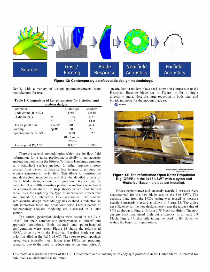
The fundamental difference from the 1980s is the design system capabilities to simultaneously optimize for both aerodynamics and acoustics which has enabled a rapid maturation of blade designs capable of meeting current noise regulations. The current generation blade designs no longer have compromised aerodynamic efficiency in order to meet noise targets. This will be shown quantitatively in the upcoming system analysis section. The current aero/acoustic design methodology is shown schematically in Fig. 12 where the starting point is a 3D viscous numerical simulation. Custom blade profiles are possible that allow for better optimized aerodynamics at the high-incidence/high-loaded takeoff condition without compromising cruise performance. This improved aerodynamics has a significant effect on noise production at the operating conditions important for community noise.
Key differences in the new blade designs are shown in Table 1. Blade count and diameter increase account for much of the noise reduction potential of the modern designs. The Historical design listed in Table 1 uses a modern blade count and spacing but with historical diameter and loading values. All of the modern designs incorporate aft blade clipping and customized blade shaping to reduce the acoustic impact of the forward rotor tip vortex. Additionally, rotor-to-rotor spacing and speed/torque ratios were optimized for maximum acoustic benefit. Some further details of the new blade designs can be found in [14]. Two generations of new designs, Gen-1 and
Figure 10: The GE36 engine development program.
7 This material is declared a work of the U.S. Government and is not subject to copyright protection in the United States. Approved for public release; distribution is unlimited.
Gen-2, with a variety of design parameters/intents were manufactured for test.
Table 1. Comparison of key parameters for historical and modern designs.
Parameter Historical Modern Blade count (R1xR2) 12x10 12x10 R1 diameter, D
m ft
3.25 10.7
4.27 14.0
Design point disk loading
kW/m2 hp/ft2
803 100
474 59
Spacing/diameter, S/D 0.28 (0.23 in the
1980s)
0.27
Design point PQA/J3 0.167 0.099 There are several methodologies which use the flow field
information for a noise prediction, typically in an acoustic analogy method using the Ffowcs Williams-Hawkings equation or a Kirchhoff surface method. In either approach, noise sources from the entire blade surface interact to produce the acoustic signature in the far field. This allows for constructive and destructive interference and thus the detailed effects of many blade design/engine configuration choices can be predicted. The 1980s acoustics prediction methods were based on empirical databases or strip theory which had limited capabilities for capturing the type of interference effects that are crucial for interaction tone generation. The current aero/acoustic design methodology has enabled a reduction in both interaction tones and broadband noise. Further details of contemporary acoustic modeling are discussed in a later section.
The current generation designs were tested in the 9x15 LSWT for their aero/acoustic performance at takeoff and approach conditions. Both isolated and pylon-installed configurations were tested. Figure 13 shows the refurbished NASA drive rig with the Historical Baseline blade set and pylon installed in the 9x15 LSWT. The rotor-to-rotor spacings tested were typically much larger than 1980s test program, primarily due to the need to reduce interaction tone noise. A
spectra from a modern blade set is shown in comparison to the Historical Baseline blade set in Figure 14 for a single directivity angle. Note the large reduction in both tonal and broadband noise for the modern blade set.
Figure 13: The refurbished Open Rotor Propulsion
Rig (ORPR) in the 9x15 LSWT with a pylon and Historical Baseline blade set installed.
Cruise performance and unsteady nearfield pressure were
characterized for the new blade sets in the 8x6 SWT. The acoustic plate from the 1980s testing was reused to measure nearfield unsteady pressure as shown in Figure 15. The cruise net efficiency for the new designs nearly met the target value of 86% as shown in Figure 16 for a 0.78 Mach condition. The new designs also maintained high net efficiency to at least 0.8 Mach, Figure 17, thus alleviating the need to fly slower to realize the benefits of open rotors.
Figure 12: Contemporary aero/acoustic design methodology.

8 This material is declared a work of the U.S. Government and is not subject to copyright protection in the United States. Approved for public release; distribution is unlimited.
Figure 14: Comparison of spectra from a legacy and a
modern blade design. From [14].
Acoustic plate
Static tube
Figure 15: Open rotor test installation in the 8x6 SWT
with acoustic plate and static tube.
Figure 16: Net efficiency at cruise 0.78 Mach
conditions [14].
Figure 17: Net efficiency versus cruise Mach number.
Diagnostics(test:(During the recent test program a series of flowfield and
acoustic diagnostic measurements were acquired in addition to the standard aerodynamic and acoustics data. Acoustic phased array, pylon installed acoustics, pressure sensitive paint, particle image velocimetry (PIV) and barrier wall/shielding acoustics measurements were all acquired with the Historical Baseline blade set. Highlights are given below.
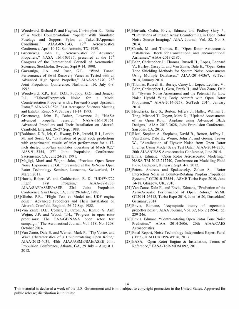
The PIV measurements were focused on the flow in the intra-rotor gap with the objective to characterize the forward rotor tip vortex and wake. An example of the data is shown in Figure 18. Since the tip vortex is a primary noise source much effort in the 1980s focused on analytic methods to predict the vortex trajectory because this was key to the aft blade design.
9 This material is declared a work of the U.S. Government and is not subject to copyright protection in the United States. Approved for public release; distribution is unlimited.
Data to validate these analytic methods was sparse and often from sources, such as helicopter rotors, that were not representative. The PIV data was used to validate the numerical flow field predictions and substantially contributed to validating the design methodology for the latter generations of blades. A more detailed comparison of vortex trajectory measurements to theory can be found in Ref [15].
Figure 18: The intra-rotor PIV data block.
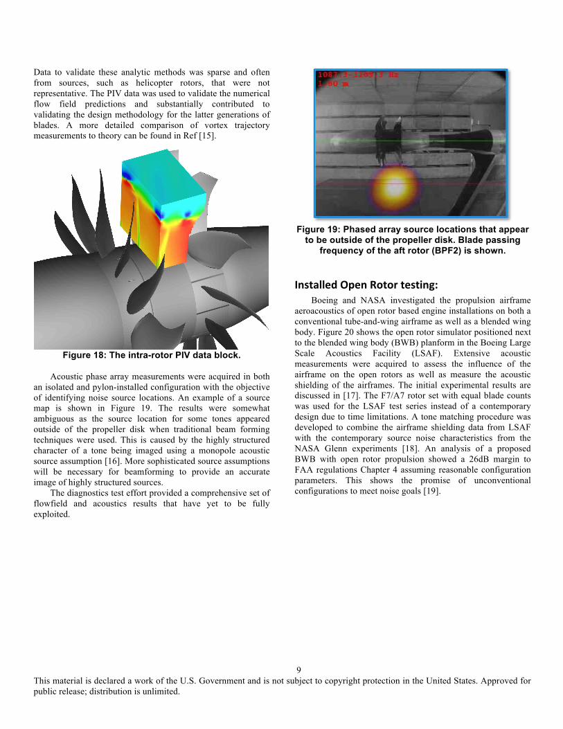
Acoustic phase array measurements were acquired in both
an isolated and pylon-installed configuration with the objective of identifying noise source locations. An example of a source map is shown in Figure 19. The results were somewhat ambiguous as the source location for some tones appeared outside of the propeller disk when traditional beam forming techniques were used. This is caused by the highly structured character of a tone being imaged using a monopole acoustic source assumption [16]. More sophisticated source assumptions will be necessary for beamforming to provide an accurate image of highly structured sources.
The diagnostics test effort provided a comprehensive set of flowfield and acoustics results that have yet to be fully exploited.
Figure 19: Phased array source locations that appear
to be outside of the propeller disk. Blade passing frequency of the aft rotor (BPF2) is shown.
Installed(Open(Rotor(testing:(Boeing and NASA investigated the propulsion airframe
aeroacoustics of open rotor based engine installations on both a conventional tube-and-wing airframe as well as a blended wing body. Figure 20 shows the open rotor simulator positioned next to the blended wing body (BWB) planform in the Boeing Large Scale Acoustics Facility (LSAF). Extensive acoustic measurements were acquired to assess the influence of the airframe on the open rotors as well as measure the acoustic shielding of the airframes. The initial experimental results are discussed in [17]. The F7/A7 rotor set with equal blade counts was used for the LSAF test series instead of a contemporary design due to time limitations. A tone matching procedure was developed to combine the airframe shielding data from LSAF with the contemporary source noise characteristics from the NASA Glenn experiments [18]. An analysis of a proposed BWB with open rotor propulsion showed a 26dB margin to FAA regulations Chapter 4 assuming reasonable configuration parameters. This shows the promise of unconventional configurations to meet noise goals [19].

10 This material is declared a work of the U.S. Government and is not subject to copyright protection in the United States. Approved for public release; distribution is unlimited.
Figure 20: The Boeing/NASA propulsion airframe
aeroacoustics experiment at LSAF.
Systems(modeling:(NASA completed a careful comparison of the fuel burn
and acoustic performance of ducted and unducted systems on a common aircraft platform [20]. Highlights are given here.
Angle-of-attack has a strong influence on the noise produced by the propellers unlike a ducted fan where the inlet buffers the AoA influence from reaching the fan rotor. In wing mounted configurations the propellers will always be exposed to a significant AoA due to wing upwash unless additional systems such as a tilting nacelle are added to the aircraft. To minimize the AoA influence, NASA designed a notional rear engine aircraft for a 3250 nautical mile mission with 162 passengers. The airframe is based on a modernized MD-90-30 aircraft with weight added to the open rotor version to account for additional noise shielding and hydraulic systems. The notional aircraft is shown in Figure 21.
Figure 21: The notional NASA aircraft with rear
mounted engines designed for 162 passengers, 3250 nautical mile mission at 0.78 cruise Mach, 35,000 feet
altitude. Aerodynamic and acoustic data from the Gen-2 blade sets
was used for the propulsor performance models. A NASA defined, advanced technology, high-bypass ratio turbofan engine was also analyzed on the same airframe. The two aircraft configurations were ‘flown’ analytically to generate ground observer noise for the certification points as well as a total fuel burn for the mission profile. The turbofan powered aircraft was predicted to have a 27% fuel burn reduction relative to the 1998 baseline with a 24 dB cumulative margin to Chapter 4. Results are shown in Figure 22 for the Gen-1 and Gen-2 open rotor designs compared to a 1998 technology baseline. As expected, the ducted system showed an acoustic advantage over the open rotor system. However, the open rotor system had ~10% fuel burn advantage with acceptable acoustics to meet current certification requirements.
GE also used the NASA aircraft design and mission profile to evaluate the fuel burn and acoustic performance of the current design, Gen-1 and Gen-2 blades, with the historical blades and notional 1990s product as summarized in Figure 23. Note that the GE engine baseline for fuel burn was the CFM56-7B, not the NASA advanced turbofan. Comparison of the ‘Historical Aero’ and ‘GE36 Product’ bars illustrates the quandary faced by 1980’s designs. The Historical Aero design is F31/A31 which was the best aerodynamic performance blade set from the 1980s and had no compromises for acoustics, except for increased blade count. The Historical Aero blades did not meet the acoustic margin for Chapter 4. The GE36 Product design was intended to meet Chapter 4 noise regulations but incurred a substantial efficiency penalty (3 points less efficient) to do so. Results from the new designs show that GE was successful at increasing the net efficiency above that of the best 1980s design while also simultaneously reducing noise. The best of the new designs is predicted to have more than 15 EPNdB cumulative margin to Chapter 4. It is difficult to communicate the acoustic impact of the new blade designs’ noise reduction so an auralization was done comparing the legacy blade set to a modern design. Details of the procedure are in [21]. The contemporary design blade sets are noticeably quieter with a ‘softer’ sound quality character.

11 This material is declared a work of the U.S. Government and is not subject to copyright protection in the United States. Approved for public release; distribution is unlimited.
Acoustic(analysis:(The code development/modeling efforts for high-speed
propellers at NASA ended when the experimental research program concluded in the early 1990s. Therefore, some ‘recovery’ of capabilities was necessary as interest in analyzing contra-rotating configurations reemerged. The highest fidelity approach to predicting the acoustic field of a high-speed propeller is a direct simulation of its unsteady pressure field everywhere within the domain of interest. The computing resources required for such a simulation make it impractical for design purposes with very few attempts to date. As previously noted, most acoustic modeling approaches make use of the
Ffowcs Williams-Hawking (FW-H) equation. See, for example, [22] and [23] for a review of these approaches.
The FW-H equation expresses the acoustic field as temporal and spatial integrals over aerodynamic source regions of interest. In general, the blade surfaces and the flowfield surrounding them constitute the regions of interest, but for most application it suffices to focus only on the blade surfaces. As a result, the FW-H equation takes the form shown in Eqn 1. It is common practice to designate the constituent terms in this equation as ‘thickness’ and ‘loading’ sources. The thickness contribution is dependent only on the propeller geometry and early prediction methods used simplified geometry models based on standard airfoil series. Similarly, loading noise is dependent only on aerodynamic loading on the blades and early
% Fuel Burn Benefit Relative to 1998 Technology Reference Vehicle!
Nois
e M
argi
n!
Initial Gen-1 Open Rotor !Fuel burn: 36% lower than ref. vehicle!Noise: 12.6 dB cum margin to Ch. 4!
Revised Gen-1 Open Rotor !Fuel burn: 35% lower than ref. vehicle!Noise: 13.6 dB cum margin to Ch. 4!
Gen-2 Open Rotor !Fuel burn: 36% lower than ref. vehicle!Noise: 16.8 dB cum margin to Ch. 4!
Advanced UHB Turbofan (BPR ~14)!Fuel burn: 27% lower than ref. vehicle!Noise: 24dB cum margin to Ch. 4 !
Figure 22: Fuel burn and acoustic comparison for an advanced turbofan and an open rotor powered aircraft.
Figure 23: Net efficiency and acoustic comparison with legacy blade sets. The CLEEN goals/baseline is used.

12 This material is declared a work of the U.S. Government and is not subject to copyright protection in the United States. Approved for public release; distribution is unlimited.
models used simplified analytic expressions for blade loading profiles. These approaches were useful in assessing the global character of propeller noise but owing to their low fidelity descriptions of the blade geometry and loading, could not reliably predict the benefits of subtle propeller design changes that could have significant impact on the acoustic signature of the propellers..
Eqn. 1: The general form of the Ffowcs Williams-Hawking equation for open rotor tone noise. The noise sources are integrated over the blade surface, S, for the appropriate time period, T. G is the Green’s function that determines propagation characteristics.
In contemporary application of the FW-H equation to
predicting the tone noise generated by high-speed propellers, the necessary blade pressure input to Eqn 1 for computing loading tone noise comes from aerodynamic simulations (typically RANS or URANS). The accuracy of the acoustic results is strongly influenced by the quality of the simulation but the approach does enable the tailoring of designs to optimize for both aerodynamics and acoustics. Figure 24 shows the magnitude of the unsteady pressure associated with the blade passing frequency tone as an example.
Results can be further interrogated to identify the regions of a blade that contribute to a particular tone. For interaction tones, such as BPF1+BPF2 tone, the entire blade span contributes to the tone level (see Figure 25). The figure shows the change in tone sound pressure level at a sideline location as the aft blade span is systematically clipped. For interaction tones, clipping the aft blade does not necessarily reduce their level and may in fact cause it to increase due to the complex interference patterns that exist amongst the loading noise sources distributed along the blade span. As such, while clipping the aft blade does reduce the aft rotor blade passing harmonic tones (i.e., nBPF2), it does little to reduce interaction tones. Therefore, other mitigation strategies like wake management are necessary to further reduce high-speed propeller noise [24].
For supersonic tip speed propellers, the so-called quadrupole source, which is associated with the flow field surrounding the blades, should also be included in order to accurately predict the noise level at the highest tip speeds [see, for example, 25]. For contemporary propeller designs, which have subsonic relative tip speeds, the quadrupole noise source contribution is not significant for community noise considerations, but may be a concern for cabin noise [26].
The current generation of blades has benefited from the ability to optimize for aero performance and acoustics.
Extensive modeling efforts continue in Europe as discussed in [1]. Efforts also continue on technologies or other strategies to reduce the noise of contra-rotating systems to levels on par with ducted fan propulsion systems.
Remaining( challenges( to( Open( Rotor(propulsion:(
Even though the recent open rotor work in the U.S. has demonstrated dramatic progress in acoustics and efficiency, there are challenges remaining to implementing an open rotor based propulsion system. Three separate but interrelated technical challenges that the research community could address are discussed here.
Firstly, the propulsion airframe integration will be challenging due to the large propeller diameter, 14 feet for a single aisle application, and the propeller noise sensitivity to AoA. Wing mounted engines tend to be preferred by airframers, but as noted earlier, the wing upwash will lead to acoustic issues with the propellers. A tail mount configuration has a more benign flowfield for the propellers but is not as easy for an airframer to ‘stretch’ for growth derivatives of the aircraft. Additionally, open rotors have demonstrated efficiency benefit relative to turbofans in isolated configurations. This efficiency advantage needs to be confirmed at cruise conditions in an installed configuration. This will require an airframe configuration designed for use with an open rotor.
Secondly, recent analysis for the noise working group of ICAO showed an increased sensitivity of noise to aircraft maximum takeoff weight (MTOW) for open rotor powered aircraft [27]. The current noise margin predicted for open rotors may not be adequate if final aircraft weight is significantly higher than design intent. Additional noise reduction
Figure 24: Example of computed unsteady blade
surface pressure.

13 This material is declared a work of the U.S. Government and is not subject to copyright protection in the United States. Approved for public release; distribution is unlimited.
technologies, beyond what has been accomplished to date, would be necessary.
Thirdly, certification requirements may limit aircraft configuration choices unless additional technology development is done. Existing regulations for engine failure and fuselage integrity are applicable [28]. For example, all 1980s flight test aircraft had the open rotor engines mounted in the rear so that the engines were shielded from each other in a blade out event and impact to the fuselage would not cause a depressurization of the passenger cabin. The diameter of the fuselage may not be adequate to shield the engines from each other due to the propeller diameters proposed for the contemporary designs. Wing mounted configurations may require fuselage shielding unless novel concepts to prevent fuselage puncture can be devised. CONCLUSIONS
Recent open rotor development effort in the United States has resulted in blade designs that have demonstrated high net efficiency, ~86%, at 0.78 Mach and low noise, >15 EPNdB cumulative margin to Chapter 4 when analyzed on a NASA derived aircraft/mission. Associated propulsion airframe aeroacoustic work with blended wing body airframes shows an even greater noise margin, ~26 EPNdB, when airframe shielding is used to reduce community noise exposure.
Challenges to implementation of open rotor based propulsion systems include propulsion airframe integration of large diameter, angle-of-attack sensitive rotors, the greater increase in propeller noise with aircraft weight than turbofan powered aircraft and certification issues. It is likely that a
dedicated aircraft/engine configuration will be required for an open rotor based engine to be successfully implemented. It appears that Europe is working towards that goal within the CleanSky Program. There are significant research opportunities for the U.S. to pursue the same goal.
ACKNOWLEDGMENTS Thanks to the NASA Environmentally Responsible
Aviation Program, Fay Collier manager, for sponsoring this publication. The contemporary work cited here also had contributions from the NASA Fixed Wing Program, NASA Aeronautics Test Program, the FAA CLEEN Program and General Electric. Ed Envia assisted with the acoustic modeling section.
REFERENCES [1] Whurr, John and Hart, Jon, “A Rolls-Royce perspective on
future Green Propulsion Systems,” Wiley Encyclopedia of Aerospace: Green Aviation, to be published 2015.
[2] Hager, R., Vrabel, D., Advanced Turboprop Project, NASA-SP-495, 1988.
[3] Hoff, G.E., “Experimental Performance and Acoustic Investigation of Modern, Counterrotating Blade Concepts,” NASA CR-185158. January 1990.
[4] Delaney, B.R., Balan, C., West, H., Humenik, F.M. and Craig, G., “A Model Propulsion Simulator for Evaluating Counter Rotating Blade Characteristics,” SAE 861715, Aerospace Technology Conference and Exhibition, Long Beach, CA, October 13-16, 1986.
Figure 25: Reduction in the first interaction tone, BPF1+BPF2, with aft rotor clipping.
14 This material is declared a work of the U.S. Government and is not subject to copyright protection in the United States. Approved for public release; distribution is unlimited.
[5] Woodward, Richard P. and Hughes, Christopher E., “Noise of a Model Counterrotation Propeller With Simulated Fuselage and Support Pylon at Takeoff/Approach Conditions,” AIAA-89-1143, 12th Aeroacoustics Conference, April 10-12, San Antonio, TX, 1989.
[6] Groeneweg, John F., “Aeroacoustics of Advanced Propellers,” NASA TM-103137, presented at the 17th Congress of the International Council of Aeronautical Sciences, Stockholm, Sweden, Sept 9-14, 1990.
[7] Gazzaniga, J.A. and Rose, G.E., “Wind Tunnel Performance of Swirl Recovery Vanes as Tested with an Advanced High Speed Propeller,” AIAA-92-3770, 28th Joint Propulsion Conference, Nashville, TN, July 6-8, 1992.
[8] Woodward, R.P., Hall, D.G., Podboy, G.G., and Jeracki, R.J., “Takeoff/Approach Noise for a Model Counterrotation Propeller with a Forward-Swept Upstream Rotor,” AIAA-93-0596, 31st Aerospace Sciences Meeting and Exhibit, Reno, NV, January 11-14, 1993.
[9] Groeneweg, John F., Bober, Lawrence J., “NASA advanced propeller research,” NASA-TM-101361, Advanced Propellers and Their Installation on Aircraft, Cranfield, England, 26-27 Sep. 1988.
[10] Boldman, D.R., Iek, C., Hwang, D.P., Jeracki, R.J., Larkin, M. and Sorin, G., “Evaluation of panel code predictions with experimental results of inlet performance for a 17-inch ducted prop/fan simulator operating at Mach 0.2,” AISS-91-3354, 27th Joint Propulsion Conference, Sacremento, CA, June 24-27, 1991.
[11] Majjigi, Muni and Wojno, John, “Previous Open Rotor Noise Experience at GE,” presented at the X-Noise Open Rotor Technology Seminar, Lausanne, Switzerland, 18 March 2011.
[12] Harris, Robert W. and Cuthbertson, R. D., “UDF™/727 Flight Test Program,” AIAA-87-1733, AIAA/SAE/ASME/ASEE 23rd Joint Propulsion Conference, San Diego, CA, June 29-July2, 1987.
[13] Gliebe, P.R., “Flight Test vs Model test UDF engine noise,” Advanced Propellers and Their Installation on Aircraft, Cranfield, England, 26-27 Sep. 1988.
[14] Van Zante, D.E., Collier, F., Orton, A., Khalid, S. Arif, Wojno, J.P. and Wood, T.H., “Progress in open rotor propulsors: The FAA/GE/NASA open rotor test campaign,” The Aeronautical Journal, Vol. 118, No. 1208, October 2014.
[15] Van Zante, Dale E. and Wernet, Mark P., “Tip Vortex and Wake Characteristics of a Counterrotating Open Rotor,” AIAA-2012-4039, 48th AIAA/ASME/SAE/ASEE Joint Propulsion Conference, Atlanta, GA, 29 July – August 1, 2012.
[16] Horvath, Csaba, Envia, Edmane and Podboy Gary P., “Limitations of Phased Array Beamforming in Open Rotor Noise Source Imaging," AIAA Journal, Vol. 52, No. 8, 2014.
[17] Czech, M. and Thomas, R., “Open Rotor Aeroacoustic Installation Effects for Conventional and Unconventional Airframes,” AIAA-2013-2185,
[18] Bahr, Christopher J., Thomas, Russell H., Lopes, Leonard V., Burley, Casey L. and Van Zante, Dale E., “Open Rotor Tone Shielding Methods for System Noise Assessments Using Multiple Databases,” AIAA-2014-0367, SciTech 2014, January 2014.
[19] Thomas, Russell H., Burley, Casey L., Lopes, Leonard V., Bahr, Christopher J., Gern, Frank H., and Van Zante, Dale E., “System Noise Assessment and the Potential for Low Noise Hybrid Wing Body Aircraft with Open Rotor Propulsion,” AIAA-2014-0258, SciTech 2014, January 2014.
[20] Hendricks, Eric S., Berton, Jeffery J., Haller, William J., Tong, Michael T., Guynn, Mark D., “Updated Assessments of an Open Rotor Airplane using Advanced Blade Designs,” AIAA 2013-3628, Joint Propulsion Conference, San Jose, CA, 2013.
[21] Rizzi, Stephen A., Stephens, David B., Berton, Jeffrey J., Van Zante, Dale E., Wojno, John P., and Goerig, Trevor W., “Auralization of Flyover Noise from Open Rotor Engines Using Model Scale Test Data,” AIAA-2014-2750, 20th AIAA/CEAS Aeroacoustics Conference, June 2014.
[22] Envia, Edmane, “Open Rotor Aeroacoustic Modeling,” NASA TM-2012-217740, Conference on Modelling Fluid Flow, Budapest, Hungary, Sept. 4-7, 2012.
[23] Peters, Andreas and Spakovszky, Zoltan S., “Rotor Interaction Noise in Counter-Rotating Propfan Propulsion Systems,” GT2010-22554 , ASME Turbo Expo 2010, June 14-18, Glasgow, UK, 2010.
[24] Van Zante, Dale E., and Envia, Edmane, “Prediction of the Aero-Acoustic Performance of Open Rotors,” ASME GT2014-26413, Turbo Expo 2014, June 16-20, Dusseldorf, Germany, 2014.
[25] Envia, Edmane, "Asymptotic theory of supersonic propeller noise", AIAA Journal, Vol. 32, No. 2 (1994), pp. 239-246.
[26] Envia, Edmane, “Contra-rotating Open Rotor Tone Noise Prediction,” AIAA 2014-2606, 20th AIAA/CAES Aeroacoustics
[27] Final Report, Noise Technology Independent Expert Panel (IEP2), ICAO CAEP/9-WP16, 2013.
[28] EASA, “Open Rotor Engine & Installation, Terms of Reference,” EASA-ToR-MDM.092, 2011.