Progress in Materials Science - Research Group of Welding ...
44
Recent advances in friction-stir welding – Process, weldment structure and properties R. Nandan a , T. DebRoy a, * , H.K.D.H. Bhadeshia b a Department of Materials Science and Engineering, Pennsylvania State University, University Park, PA 16802, USA b Department of Materials Science and Metallurgy, University of Cambridge, Cambridge CB2 3QZ, UK article info Article history: Received 7 May 2008 Accepted 18 May 2008 abstract Friction-stir welding is a refreshing approach to the joining of met- als. Although originally intended for aluminium alloys, the reach of FSW has now extended to a variety of materials including steels and polymers. This review deals with the fundamental understand- ing of the process and its metallurgical consequences. The focus is on heat generation, heat transfer and plastic flow during welding, elements of tool design, understanding defect formation and the structure and properties of the welded materials. Ó 2008 Elsevier Ltd. All rights reserved. Contents 1. Introduction ........................................................................ 981 2. FSW process ........................................................................ 982 2.1. Heat generation ............................................................... 982 2.2. Principles of heat transfer and material flow ....................................... 984 2.3. Material flow and mechanism of joining ........................................... 988 2.4. Temperature fields and cooling rates .............................................. 993 2.5. Welding variables ............................................................. 997 2.6. Tool design................................................................... 998 2.7. Defects ..................................................................... 1001 2.8. Residual stress ............................................................... 1003 3. Microstructure and properties of friction-stir welded alloys................................. 1005 3.1. Aluminium alloys ............................................................ 1005 3.2. Magnesium alloys ............................................................ 1009 3.3. Copper alloys ................................................................ 1009 3.4. Titanium alloys .............................................................. 1009 3.5. Steels ...................................................................... 1010 0079-6425/$ - see front matter Ó 2008 Elsevier Ltd. All rights reserved. doi:10.1016/j.pmatsci.2008.05.001 * Corresponding author. E-mail addresses: [email protected] (T. DebRoy), [email protected] (H.K.D.H. Bhadeshia). Progress in Materials Science 53 (2008) 980–1023 Contents lists available at ScienceDirect Progress in Materials Science journal homepage: www.elsevier.com/locate/pmatsci
Transcript of Progress in Materials Science - Research Group of Welding ...
Progress in Materials Science 53 (2008) 980–1023
Contents lists available at ScienceDirect
Progress in Materials Science
j o u r n a l h o m e p a g e : w w w . e l s e v i e r . c o m / l o c a t e / p m a t s c i
Recent advances in friction-stir welding – Process,weldment structure and properties
R. Nandan a, T. DebRoy a,*, H.K.D.H. Bhadeshia b
a Department of Materials Science and Engineering, Pennsylvania State University, University Park, PA 16802, USAb Department of Materials Science and Metallurgy, University of Cambridge, Cambridge CB2 3QZ, UK
a r t i c l e i n f o a b s t r a c t
Article history:Received 7 May 2008Accepted 18 May 2008
0079-6425/$ - see front matter � 2008 Elsevier Ltdoi:10.1016/j.pmatsci.2008.05.001
* Corresponding author.E-mail addresses: [email protected] (T. DebRoy), [email protected] (H.K.D.H. Bhadeshia).
Friction-stir welding is a refreshing approach to the joining of met-als. Although originally intended for aluminium alloys, the reach ofFSW has now extended to a variety of materials including steelsand polymers. This review deals with the fundamental understand-ing of the process and its metallurgical consequences. The focus ison heat generation, heat transfer and plastic flow during welding,elements of tool design, understanding defect formation and thestructure and properties of the welded materials.
� 2008 Elsevier Ltd. All rights reserved.
Contents
1. Introduction . . . . . . . . . . . . . . . . . . . . . . . . . . . . . . . . . . . . . . . . . . . . . . . . . . . . . . . . . . . . . . . . . . . . . . . . 9812. FSW process . . . . . . . . . . . . . . . . . . . . . . . . . . . . . . . . . . . . . . . . . . . . . . . . . . . . . . . . . . . . . . . . . . . . . . . . 982
2.1. Heat generation . . . . . . . . . . . . . . . . . . . . . . . . . . . . . . . . . . . . . . . . . . . . . . . . . . . . . . . . . . . . . . . 9822.2. Principles of heat transfer and material flow . . . . . . . . . . . . . . . . . . . . . . . . . . . . . . . . . . . . . . . 9842.3. Material flow and mechanism of joining . . . . . . . . . . . . . . . . . . . . . . . . . . . . . . . . . . . . . . . . . . . 9882.4. Temperature fields and cooling rates. . . . . . . . . . . . . . . . . . . . . . . . . . . . . . . . . . . . . . . . . . . . . . 9932.5. Welding variables . . . . . . . . . . . . . . . . . . . . . . . . . . . . . . . . . . . . . . . . . . . . . . . . . . . . . . . . . . . . . 9972.6. Tool design. . . . . . . . . . . . . . . . . . . . . . . . . . . . . . . . . . . . . . . . . . . . . . . . . . . . . . . . . . . . . . . . . . . 9982.7. Defects . . . . . . . . . . . . . . . . . . . . . . . . . . . . . . . . . . . . . . . . . . . . . . . . . . . . . . . . . . . . . . . . . . . . . 10012.8. Residual stress . . . . . . . . . . . . . . . . . . . . . . . . . . . . . . . . . . . . . . . . . . . . . . . . . . . . . . . . . . . . . . . 1003
3. Microstructure and properties of friction-stir welded alloys. . . . . . . . . . . . . . . . . . . . . . . . . . . . . . . . . 1005
3.1. Aluminium alloys . . . . . . . . . . . . . . . . . . . . . . . . . . . . . . . . . . . . . . . . . . . . . . . . . . . . . . . . . . . . 10053.2. Magnesium alloys . . . . . . . . . . . . . . . . . . . . . . . . . . . . . . . . . . . . . . . . . . . . . . . . . . . . . . . . . . . . 10093.3. Copper alloys . . . . . . . . . . . . . . . . . . . . . . . . . . . . . . . . . . . . . . . . . . . . . . . . . . . . . . . . . . . . . . . . 10093.4. Titanium alloys . . . . . . . . . . . . . . . . . . . . . . . . . . . . . . . . . . . . . . . . . . . . . . . . . . . . . . . . . . . . . . 10093.5. Steels . . . . . . . . . . . . . . . . . . . . . . . . . . . . . . . . . . . . . . . . . . . . . . . . . . . . . . . . . . . . . . . . . . . . . . 1010d. All rights reserved.
R. Nandan et al. / Progress in Materials Science 53 (2008) 980–1023 981
3.5.1. Role of thermomechanical processing. . . . . . . . . . . . . . . . . . . . . . . . . . . . . . . . . . . . . . 10113.5.2. Corrosion. . . . . . . . . . . . . . . . . . . . . . . . . . . . . . . . . . . . . . . . . . . . . . . . . . . . . . . . . . . . . 10133.5.3. FSW of martensite in mild steel . . . . . . . . . . . . . . . . . . . . . . . . . . . . . . . . . . . . . . . . . . 10133.5.4. FSW of steels at T < Ac1 . . . . . . . . . . . . . . . . . . . . . . . . . . . . . . . . . . . . . . . . . . . . . . . . . 10143.5.5. Hardness of stir zone . . . . . . . . . . . . . . . . . . . . . . . . . . . . . . . . . . . . . . . . . . . . . . . . . . . 1015
4. Outlook and remarks . . . . . . . . . . . . . . . . . . . . . . . . . . . . . . . . . . . . . . . . . . . . . . . . . . . . . . . . . . . . . . . . 1016Acknowledgements . . . . . . . . . . . . . . . . . . . . . . . . . . . . . . . . . . . . . . . . . . . . . . . . . . . . . . . . . . . . . . . 1017References . . . . . . . . . . . . . . . . . . . . . . . . . . . . . . . . . . . . . . . . . . . . . . . . . . . . . . . . . . . . . . . . . . . . . . 1017
1. Introduction
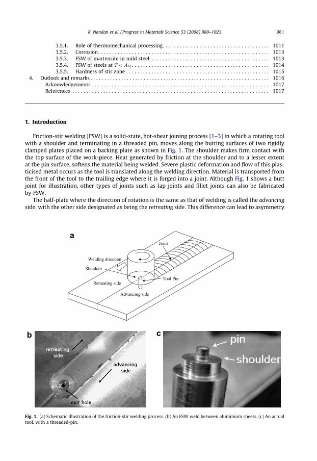
Friction-stir welding (FSW) is a solid-state, hot-shear joining process [1–3] in which a rotating toolwith a shoulder and terminating in a threaded pin, moves along the butting surfaces of two rigidlyclamped plates placed on a backing plate as shown in Fig. 1. The shoulder makes firm contact withthe top surface of the work-piece. Heat generated by friction at the shoulder and to a lesser extentat the pin surface, softens the material being welded. Severe plastic deformation and flow of this plas-ticised metal occurs as the tool is translated along the welding direction. Material is transported fromthe front of the tool to the trailing edge where it is forged into a joint. Although Fig. 1 shows a buttjoint for illustration, other types of joints such as lap joints and fillet joints can also be fabricatedby FSW.
The half-plate where the direction of rotation is the same as that of welding is called the advancingside, with the other side designated as being the retreating side. This difference can lead to asymmetry
Retreating side
Advancing side
Welding direction
Shoulder
Tool Pin
Joint
a
b c
Fig. 1. (a) Schematic illustration of the friction-stir welding process. (b) An FSW weld between aluminium sheets. (c) An actualtool, with a threaded-pin.

982 R. Nandan et al. / Progress in Materials Science 53 (2008) 980–1023
in heat transfer [4], material flow and the properties of the two sides of the weld. For example, thehardness of particular age-hardened aluminium alloys tends to be lower in the heat-affected zoneon the retreating side, which then becomes the location of tensile fracture in cross-weld tests [5]; thisis also the case for pure titanium [6].
Since its discovery in 1991 [1], FSW has evolved as a technique of choice in the routine joining ofaluminium components; its applications for joining difficult metals and metals other than aluminiumare growing, albeit at a slower pace. There have been widespread benefits resulting from the applica-tion of FSW in for example, aerospace, shipbuilding, automotive and railway industries [7].
FSW involves complex interactions between a variety of simultaneous thermomechanical pro-cesses. The interactions affect the heating and cooling rates, plastic deformation and flow, dynamicrecrystallization [8] phenomena and the mechanical integrity of the joint. A typical cross-section ofthe FSW joint consists of a number of zones (Fig. 2) [9–12]. The heat-affected zone (HAZ) is similarto that in conventional welds although the maximum peak temperature is significantly less thanthe solidus temperature, and the heat source is rather diffuse. This can lead to somewhat differentmicrostructures when compared with fusion welding processes. The central nugget region containingthe ‘‘onion-ring” appearance is the one which experiences the most severe deformation, and is a con-sequence of the way in which a threaded tool deposits material from the front to the back of the weld.The thermomechanically affected zone (TMAZ) lies between the HAZ and nugget; the grains of the ori-ginal microstructure are retained in this region, but often in a deformed state.
A unique feature of the friction-stir welding process is that the transport of heat is aided by theplastic flow of the substrate close to the rotating tool. The heat and mass transfer depend on materialproperties as well as welding variables including the rotational and welding speeds of the tool and itsgeometry. In FSW, the joining takes place by extrusion and forging of the metal at high strain rates.Jata and Semiatin estimated a typical deformation strain rate of 10 s�1 by measuring grain-size andusing a correlation between grain-size and Zener–Holloman parameter which is temperature compen-sated strain rate [13]. Kokawa et al. estimated an effective strain rates in the range 2–3 s�1 [14]. Theplastic flow must clearly feature in any theory for the process, and the behaviour of the metal at highstrain rates, its dynamic recrystallization behaviour and the effects of heating and cooling must also beconsidered.
The role of welding parameters, tool design, the initial process modelling, and the microstructureand properties of the FSW joints have been reviewed previously [15,16]. It is nevertheless a relativelynew process and one which is evolving rapidly. As a result, a periodic critical assessment of our under-standing of the welding process as well as the structure and properties of the welded materials islikely to be helpful. This is the aim of the paper.
2. FSW process
2.1. Heat generation
During FSW, heat is generated by friction between the tool and the work-piece and via plasticdeformation. A fraction of the plastic deformation energy is stored within the thermomechanicallyprocessed region in the form of increased defect densities. In the weld, a mixture of recovery and
Fig. 2. Schematic cross-section of a typical FSW weld showing four distinct zones: (A) base metal, (B) heat-affected, (C)thermomechanically affected and (D) stirred (nugget) zone [9].
R. Nandan et al. / Progress in Materials Science 53 (2008) 980–1023 983
recrystallization phenomena occur simultaneously [17]. Deformation not only increases the disloca-tion density but also the amount of grain surface and grain edge per unit volume [18] and by cuttingprecipitates may force them to dissolve [19–24].
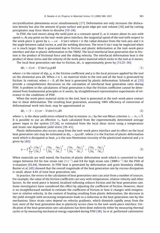
In FSW, the tool moves along the weld joint at a constant speed U, as it rotates about its axis withspeed x. At any point on the tool–work-piece interface, the tangential speed of the tool with respect tothe work-piece is given by vr ¼ xr � U sin h where r is the radial distance from the tool-axis and h isthe angle between radial vector, r, and the welding direction. The term U sin h may be neglected whenxr is much larger. Heat is generated due to friction and plastic deformation at the tool–work-pieceinterface and due to plastic deformation in the TMAZ. The local interfacial heat generation due to fric-tion is the product of frictional force and the sliding velocity. The interfacial deformation heat is theproduct of shear stress and the velocity of the work-piece material which sticks to the tool as it moves.
The local heat generation rate due to friction, d _ef , is approximately given by [15,25–36]:
d _ef ¼ dðxr � U sin hÞlf pdA ð1Þ
where d is the extent of slip, lf is the friction coefficient and p is the local pressure applied by the toolon the elemental area dA. When d is 1, no material sticks to the tool and all the heat is generated byfriction. In contrast, when d ¼ 0, all the heat is generated by plastic deformation. Schmidt et al. [33]provide a comprehensive discussion on the calculation of interfacial heat generation rates duringFSW. A problem in the calculations of heat generation is that the friction coefficient cannot be deter-mined from fundamental principles or it seems, by straightforward representative experiments of rel-evance to the conditions of FSW.
When the work-piece material sticks to the tool, heat is generated at the tool–work-piece contactdue to shear deformation. The resulting heat generation, assuming 100% efficiency of conversion ofdeformational work into heat, may be approximated as
d _es ¼ ð1� dÞðxr � U sin hÞsY dA ð2Þ
where sY is the shear yield stress related to that in tension ðrYÞ by the von Mises criterion sY ¼ rY=ffiffiffi3p
.It is possible to use an effective sY, back calculated from the experimentally determined averagepower input to the system [37,38], or estimated from the local shear stress using a temperatureand strain rate dependent yield stress [39–41].
Plastic deformation also occurs away from the tool–work-piece interface and its effect on the localheat generation rate may be estimated as d _ep ¼ bl/dV , where b is the fraction of plastic deformationwork which is dissipated as heat, l is the non-Newtonian viscosity of the plasticized material and / isgiven by [42]:
/ ¼ 2X3
i¼1
oui
oxi
� �2
þ ou1
ox2þ ou2
ox1
� �2
þ ou1
ox3þ ou3
ox1
� �2
þ ou3
ox2þ ou2
ox3
� �2
ð3Þ
When materials are well mixed, the fraction of plastic deformation work which is converted to heatranges between 0.6 for low strain rate (1 s�1) and 0.8 for high strain rate (3000 s�1) for the FSW ofa-titanium [43,44]. However, in FSW heat is generated by deformation and grain boundary sliding.Bastier et al. [45] showed that the overall magnitude of the heat generation rate by viscous dissipationis small, about 4.4% of total heat generation rate.
In practice, the errors in the calculation of heat generation rates can arise from a number of sources.For example, the value of the friction coefficient can vary with temperature, relative velocity and otherfactors. As the work-piece is heated, localised softening reduces friction and the heat generation rate.Some investigators have considered this effect by adjusting the coefficient of friction. However, thereis no straightforward method to estimate the coefficient of friction or how it changes with tempera-ture or relative velocity. In the context of heating resulting from plastic deformation, the decrease inthe yield strength with increasing temperature leads to a reduction in the heat generation rate by thismechanism. Since strain rates depend on velocity gradients, which diminish rapidly away from thetool, most of the heat generation due to plasticity occurs close to the tool–work-piece interface. Ver-ification of the heat generation rate calculations has been done indirectly either by measuring thermalcycles or by measuring mechanical energy expended during FSW [38]. Su et al. performed calorimetric
984 R. Nandan et al. / Progress in Materials Science 53 (2008) 980–1023
studies on friction-stir spot welds of AA 6111 [46]. After welding, they transferred the work-piece intoan insulated flask of oil and measured the temperature increase of the oil thus determining the heatcontent by calorimetry [46].
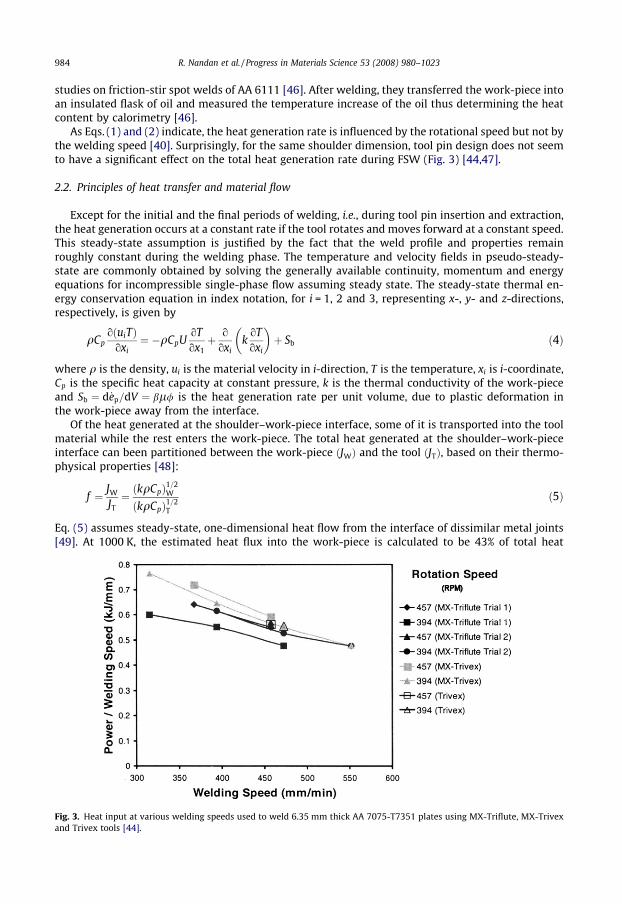
As Eqs. (1) and (2) indicate, the heat generation rate is influenced by the rotational speed but not bythe welding speed [40]. Surprisingly, for the same shoulder dimension, tool pin design does not seemto have a significant effect on the total heat generation rate during FSW (Fig. 3) [44,47].
2.2. Principles of heat transfer and material flow
Except for the initial and the final periods of welding, i.e., during tool pin insertion and extraction,the heat generation occurs at a constant rate if the tool rotates and moves forward at a constant speed.This steady-state assumption is justified by the fact that the weld profile and properties remainroughly constant during the welding phase. The temperature and velocity fields in pseudo-steady-state are commonly obtained by solving the generally available continuity, momentum and energyequations for incompressible single-phase flow assuming steady state. The steady-state thermal en-ergy conservation equation in index notation, for i = 1, 2 and 3, representing x-, y- and z-directions,respectively, is given by
Fig. 3.and Tri
qCpoðuiTÞ
oxi¼ �qCpU
oTox1þ o
oxik
oToxi
� �þ Sb ð4Þ
where q is the density, ui is the material velocity in i-direction, T is the temperature, xi is i-coordinate,Cp is the specific heat capacity at constant pressure, k is the thermal conductivity of the work-pieceand Sb ¼ d _ep=dV ¼ bl/ is the heat generation rate per unit volume, due to plastic deformation inthe work-piece away from the interface.
Of the heat generated at the shoulder–work-piece interface, some of it is transported into the toolmaterial while the rest enters the work-piece. The total heat generated at the shoulder–work-pieceinterface can been partitioned between the work-piece ðJWÞ and the tool ðJTÞ, based on their thermo-physical properties [48]:
f ¼ JW
JT¼ ðkqCpÞ1=2
W
ðkqCpÞ1=2T
ð5Þ
Eq. (5) assumes steady-state, one-dimensional heat flow from the interface of dissimilar metal joints[49]. At 1000 K, the estimated heat flux into the work-piece is calculated to be 43% of total heat
Heat input at various welding speeds used to weld 6.35 mm thick AA 7075-T7351 plates using MX-Triflute, MX-Trivexvex tools [44].
R. Nandan et al. / Progress in Materials Science 53 (2008) 980–1023 985
generated in 1018 Mn steel welded using tungsten tool. This relation has been examined experimen-tally by Lienert et al. [48] and found to be reliable.
The extent of slip can be estimated by curve fitting the measured values at various relative veloc-ities [50]:
d ¼ 0:2þ 0:8 1� exp �d0xr
x0RS
� �� �ð6Þ
where d0 is an adjustable parameter, RS is the radius of the tool shoulder, x0 is the normalising rota-tional velocity which can be taken as the mid-point of the range of rotational speeds.
Values of friction coefficient can be estimated considering the relative velocity between the tooland the work-piece according to previous work in the context of friction [51]. The relative velocity in-creases from zero at the axis of rotation to xRS at the periphery of the tool shoulder. The available datacan be fitted in the following form [51]
lf ¼ l0 exp �dxr
x0RS
� �
where l0 is a fitting constant.The boundary condition for heat exchange between the top surface of the work-piece and the sur-roundings beyond the shoulder involves consideration of both convective and radiative heat transfer as
�koToz
����top¼ r�ðT4 � T4
aÞ þ hðT � TaÞ ð7Þ
where r is the Stefan–Boltzmann constant ð5:67� 10�12 J K�4 cm�2 s�1Þ, � is the emissivity, Ta is theambient temperature and h is the heat transfer coefficient at the top surface.
At the bottom surface, the heat transfer into the backing plate is modelled by an enhanced heattransfer coefficient [38]:
koToz
����bottom
¼ hbðT � TaÞ ð8Þ
where hb is the heat transfer coefficient at the bottom surface. Several investigators [37,38,52,49] haveexamined the important role played by the boundary conditions at the bottom surface. Khandkar et al.[38] reported that for FSW of AA 6061-T651 plates, an overall convective heat transfer coefficient of1000 W m�2 K�1 might be appropriate for the bottom surface of the work-piece if the backing plateis not considered. However, they observed that when a stainless steel backing plate is taken into ac-count, a variable gap conductance would be appropriate for the work-piece/backing plate interface,and recommended an average gap conductance somewhat less than 5000 W m�2 K�1. They suggestedthat significant variations in the heat transfer rates can occur depending on the specific experimentalconditions and recommended determining the rate experimentally. Since the accuracy of the computedtemperature field depends on the value of the heat transfer coefficient, the uncertainty in the heattransfer coefficient can significantly affect the reliability of the computed temperature field. Significantimprovement in the reliability of the model predictions can be achieved by determining the uncertainparameters, such as the heat transfer coefficient using a limited volume of experimental data. This ap-proach has been tested for FSW of dissimilar aluminum alloys [53] and for fusion welding [54–57].
In recent years there has been a growing recognition of the importance of materials flow in the cal-culations of heat transfer during friction-stir welding. These calculations have adapted two ap-proaches in the modelling of flow. In many calculations, the plasticised material was treated as ahigh viscosity fluid and the flow field was obtained using computational fluid dynamics. In some othercases the plastic deformation was modelled from the principles of solid mechanics using the finite vol-ume method to solve for displacements.
The continuity equation for incompressible flow is given by
oui
oxi¼ 0 ð9Þ
986 R. Nandan et al. / Progress in Materials Science 53 (2008) 980–1023
The momentum conservation equations with reference to a coordinate system with origin at the tool-axis and moving with the tool at a constant speed U along the x-axis are:
qouiuj
oxi¼ � oP
oxjþ o
oxil ouj
oxiþ l oui
oxj
� �� qU
ouj
ox1ð10Þ
where P is the pressure. Notice that in contrast to Eq. (1) where p is the pressure applied by the tool onthe work-piece, P is a relative pressure which drives flow.
The speeds with which material moves at the tool pin periphery, u, v and w, along the weldingdirection, the normal to the welding direction in the plane of the plate being welded, and normal tothe plane of the plate, respectively, are given by
u ¼ ð1� dÞðxr sin h� UÞ; v ¼ ð1� dÞxr cos h; w ¼ Wx ð11Þ
where W is the pitch of the threads on the cylindrical tool. At the shoulder w ¼ 0.The non-Newtonian viscosity l must be estimated as a function of strain rate and temperature
using experimentally determined constitutive equations for the material of interest. According to Per-zyna, l can be expressed in terms of effective flow stress re (i.e. deviatoric stress) and effective strainrate _� (i.e. deviatoric strain rate) [58],
l ¼ re
3 _�; where _� ¼ 2
3_�ij _�ij
� �12
and _�ij ¼12
oui
oxjþ ouj
oxi
� �ð12Þ
The strain rate is found to correlate with the flow stress and temperature as follows [59]:
_� ¼ Aðsinh areÞn exp � QRT
� �ð13Þ
where the material constants A, n, a and the apparent activation energy Q are derived by fitting theequation to experimental data, and are all independent of temperature. On rearranging this equation[60,61],
re ¼1a
sinh�1 ZA
� �1n
" #ð14Þ
where Z ¼ _� expðQ=RTÞ is known as the Zener–Holloman temperature compensated strain rate [62].Sheppard and Jackson determined the fitting constants for a number of aluminium alloys [63]. Bruschiet al. [64] studied hot workability of Ti–6Al–4V alloys and estimated values of the constants in theconstitutive equation for this alloy. Material constants could be determined for other alloys fromhot working literature.
The computed variation of viscosity as a function of strain rate and temperature has been reportedfor several materials: 6061 aluminium alloys [39], 304 stainless steel [40] and 1018 C–Mn steel [41].Fig. 4 shows that the viscosity decreases significantly with both strain rate and temperature with theformer being the dominant factor for the conditions typical of FSW.
It should be emphasised that in Eq. (13), the parameters A, n and a are strictly functions of strain ina work-hardening solid. However, they should become independent of strain once a steady-state isreached during deformation in which the work-hardening is balanced by recovery-softening. Gener-ally this state is reached before strain drops to a low value, � ¼ 1, and since the strains involved inFSW are much larger, it may be assumed that a single set of material constants corresponding to stea-dy-state deformation can be utilised with the assumption that they are independent of strain.
Most of the recent studies have considered the temperature dependent thermal conductivity, spe-cific heat and yield stress for the work-piece [39,41,40,66,67,65]. The tool material commonly used forthe FSW of aluminium alloys, steels and Ti–6Al–4V are tool steel and tungsten, respectively. Table 1presents the thermophysical properties for these alloys.
Plastic deformation can be modeled using solid mechanics, which, solves for displacements insteadof velocities. Ulysse [65] used a solid mechanics approach assuming a rigid-visco-plastic materialwhere the flow stress depended on strain rate and temperature. The heat generation rate was

Fig. 4. Computed contours of log10 (viscosity in Pa s) as a function of temperature and strain rate for (a) AA 6061-T6 [39]; (b)1018 C–Mn steel [41].
R. Nandan et al. / Progress in Materials Science 53 (2008) 980–1023 987
expressed as the product of the effective stress and the effective strain rate. Temperature profiles weredetermined for the work-piece and the tool, using a three-dimensional finite analysis code.
Schmidt et al. [36] used adaptive boundary conditions to determine conditions for void-free weldsusing finite element analysis and flow stress determined according to the Johnson–Cook law. Buffa etal. [68] developed a thermomechanically coupled, rigid-visco-plastic, three-dimensional finite ele-ment model to study the effect of tool geometry and welding velocity on material flow pattern andthe grain-size distribution in the welded joints.
In the finite element method, the mechanical response on an element is obtained using forcebalance:
q€uþ c _uþ ku ¼ p ð15Þ
where q is the density, c the damping coefficient, k the stiffness coefficient, p the body force, u is thedisplacement vector, _u is the velocity vector and _u is the acceleration. In a finite element framework,the equation can be written as
M€uþ C _uþ Ku ¼ P ð16Þ
where M is the discrete mass matrix, C the viscous damping matrix, K the stiffness matrix, P the vectorof external discrete forces, which include body forces, surface forces and concentrated loads acting onthe system, and u, _u and €u are the nodal displacement, velocity and acceleration vectors, respectively.The thermal response is governed by an energy balance:
qCp_T ¼ d
dxik
dTdxi
� �þ gsij _�ij
pl ð17Þ
where Cp is the specific heat capacity at constant pressure, _T is the rate of change of temperature withtime, k the thermal conductivity, g the fraction of plastic energy dissipation, sij the deviatoric stresstensor and _�ij
pl is the plastic strain rate tensor. In FE framework, we obtain
C _Tþ BT ¼ S ð18Þ
where C is the discrete capacity matrix, B the conductivity matrix, S the source vector accounting forall thermal sources and T and _T are the nodal temperature and temperature rate vectors, respectively.
Since FSW involves large plastic deformation analogous to ballistic impact, an Eulerian finite-dif-ference code that simulates shock-wave in 3D by solving time-dependent continuum mechanics equa-tions has also been used to model friction-stir welding in aluminium [69,70]. This code is well suitedfor modelling very large deformations at high strain rate.
In polycrystalline materials, large plastic deformation alters microstructure and changes proper-ties. Boyce et al. [71] suggested that to adequately model the deformation of a polycrystalline material,
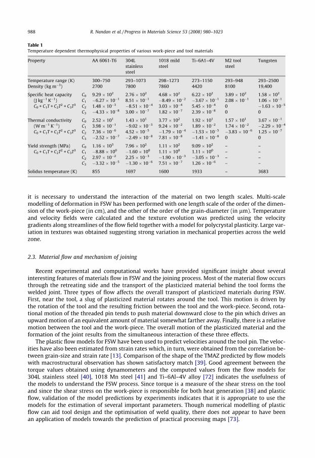
Table 1Temperature dependent thermophysical properties of various work-piece and tool materials
Property AA 6061-T6 304Lstainlesssteel
1018 mildsteel
Ti–6A1–4V M2 toolsteel
Tungsten
Temperature range (K) 300–750 293–1073 298–1273 273–1150 293–948 293–2500Density (kg m�3) 2700 7800 7860 4420 8100 19,400
Specific heat capacity(J kg�1 K�1)C0 + C1T + C2T2 + C3T3
C0 9.29 � 102 2.76 � 102 4.68 � 102 6.22 � 102 3.89 � 102 1.58 � 102
C1 �6.27 � 10�1 8.51 � 10�1 �8.49 � 10�2 �3.67 � 10�1 2.08 � 10�1 1.06 � 10�1
C2 1.48 � 10�3 �8.51 � 10�4 3.03 � 10�4 5.45 � 10�4 0 �1.63 � 10�5
C3 �4.33 � 10�8 3.00 � 10�7 1.82 � 10�7 2.39 � 10�8 0 0
Thermal conductivity(W m�1 K�1)C0 + C1T + C2T2 + C3T3
C0 2.52 � 101 1.43 � 101 3.77 � 102 1.92 � 101 1.57 � 101 3.67 � 10�1
C1 3.98 � 10�1 �9.02 � 10�3 9.24 � 10�2 1.89 � 10�2 1.74 � 10�2 �2.29 � 10�4
C2 7.36 � 10�6 4.52 � 10�5 �1.79 � 10�4 �1.53 � 10�5 �3.83 � 10�6 1.25 � 10�7
C3 �2.52 � 10�7 �2.49 � 10�8 7.81 � 10�8 �1.41 � 10�8 0 0
Yield strength (MPa)C0 + C1T + C2T2 + C3T3
C0 1.16 � 103 7.96 � 102 1.11 � 102 9.09 � 102 – –C1 �8.88 � 100 �1.60 � 100 1.11 � 100 1.11 � 100 – –C2 2.97 � 10�2 2.25 � 10�3 �1.90 � 10�3 �3.05 � 10�3 – –C3 �3.32 � 10�5 �1.30 � 10�6 7.51 � 10�7 1.26 � 10�6 – –
Solidus temperature (K) 855 1697 1600 1933 – 3683
988 R. Nandan et al. / Progress in Materials Science 53 (2008) 980–1023
it is necessary to understand the interaction of the material on two length scales. Multi-scalemodelling of deformation in FSW has been performed with one length scale of the order of the dimen-sion of the work-piece (in cm), and the other of the order of the grain-diameter (in lm). Temperatureand velocity fields were calculated and the texture evolution was predicted using the velocitygradients along streamlines of the flow field together with a model for polycrystal plasticity. Large var-iation in textures was obtained suggesting strong variation in mechanical properties across the weldzone.
2.3. Material flow and mechanism of joining
Recent experimental and computational works have provided significant insight about severalinteresting features of materials flow in FSW and the joining process. Most of the material flow occursthrough the retreating side and the transport of the plasticized material behind the tool forms thewelded joint. Three types of flow affects the overall transport of plasticized materials during FSW.First, near the tool, a slug of plasticized material rotates around the tool. This motion is driven bythe rotation of the tool and the resulting friction between the tool and the work-piece. Second, rota-tional motion of the threaded pin tends to push material downward close to the pin which drives anupward motion of an equivalent amount of material somewhat farther away. Finally, there is a relativemotion between the tool and the work-piece. The overall motion of the plasticized material and theformation of the joint results from the simultaneous interaction of these three effects.
The plastic flow models for FSW have been used to predict velocities around the tool pin. The veloc-ities have also been estimated from strain rates which, in turn, were obtained from the correlation be-tween grain-size and strain rate [13]. Comparison of the shape of the TMAZ predicted by flow modelswith macrostructural observation has shown satisfactory match [39]. Good agreement between thetorque values obtained using dynamometers and the computed values from the flow models for304L stainless steel [40], 1018 Mn steel [41] and Ti–6Al–4V alloy [72] indicates the usefulness ofthe models to understand the FSW process. Since torque is a measure of the shear stress on the tooland since the shear stress on the work-piece is responsible for both heat generation [38] and plasticflow, validation of the model predictions by experiments indicates that it is appropriate to use themodels for the estimation of several important parameters. Though numerical modelling of plasticflow can aid tool design and the optimisation of weld quality, there does not appear to have beenan application of models towards the prediction of practical processing maps [73].

R. Nandan et al. / Progress in Materials Science 53 (2008) 980–1023 989
The computed stream traces on horizontal planes around the tool pin at three different elevationsare shown in Fig. 5. The stream lines indicate the presence of rotational zone, which clearly shows therecirculating flow of a plug of material around the tool pin. The thickness of the recirculating materialflow region is affected by material properties, welding parameters and rate of heat transfer into thetool. This zone occupies larger areas at higher elevation planes due to greater momentum transportfrom the rotating shoulder. The streamlines indicate that beyond the region of recirculating plasticflow, i.e. in the transition zone, material transfer occurs mainly on the retreating side. Fig. 5 also showsa flow reversal in the advancing side close to the pin, leading to a relatively stagnant zone, whichforms closer to the pin at lower elevations. An important consequence of the lack of adequate materialflow on the advancing side has been related to the formation of ‘‘wormhole” defects [74]. The stream-lines show that beyond the rotational zone the material transport occurs mainly along the retreatingside. Flow visualisation using tracers also indicates the presence of a zone where the material rotatesand advances with the tool and transitional zone where the materials move on the retreating side [75–77].
The maximum velocity is attained near the edge of the shoulder at the top surface of the work-piece followed by a rapid decrease away from this region [39–41], as shown in Fig. 6. At planes nearthe bottom of the work-piece, the peaks in velocity were attained near the tool surface. The computedviscosity contours at different horizontal planes (Fig. 6) shows that the viscosity lies in the range of 105
to 5 � 106 Pa s for FSW of aluminium alloys. It is also seen that no significant flow occurs when the
Fig. 5. Stream traces on different horizontal planes (a) 0.35 mm, (b) 1.59 mm and (c) 2.28 mm below the top surface for a 304stainless steel plate of thickness 3.18 mm. Welding speed 4 mm s�1 with tool rotation at 300 rpm [40].

Fig. 6. Spatial variation of viscosity and velocity in AA 6061-T6 [39] at planes corresponding to z = 1.27, 4.67, 8.07 and11.47 mm for a plate thickness of 12.7 mm. Distances in x- and y-direction were equivalent, but that in the z-direction wasincreased eight-fold to enhance clarity. The welding velocity was 1.59 mm s�1 and the rotational speed was 637 rpm.
990 R. Nandan et al. / Progress in Materials Science 53 (2008) 980–1023
viscosity is higher than about 5 � 106 Pa s and that the region of plastic flow decreases with depth. Itwas observed that plastic flow ceases beyond a certain critical value of viscosity. This cut-off viscositysurface defines the geometry of the thermomechanically affected zone [39].
The flow during FSW differs in character from material flow in the liquid state during conventionalfusion welding. This is evident from studies of the welding of dissimilar metals. During fusion welding,the weld pool becomes compositionally homogenous after solidification. However, during FSW of dis-similar metals, mixing does not occur in atomic scale, and it is possible to find larger concentrationdifferences in the weld metal and the region is far from homogenous. For example, Fig. 7 shows a dif-fusion couple formation between Fe and Ni at a certain location in stir region, when pure Fe and Niplates are joined together using FSW. The diffusion couple has a length scale of only 2–3 lm. Such dif-fusion couples would not exist had melting and homogenisation of weld metal occurred.
During FSW, the material near the top of the work-piece is stirred under the action of the shoulderand vertical component of motion occurs mainly due to threading on the tool pin. The stirred materialfrom the top is carried down by the threads and deposited in the weld nugget. The vertical mixing be-comes prominent at low weld pitch, which is the ratio of welding speed to rotational speed. One way to
Fig. 7. Concentration profiles of Fe and Ni at a location in stir region for FSW of pure Fe and Ni. Points represent data obtainedby atomic emission spectroscopy and the solid lines indicate computed results [78].
R. Nandan et al. / Progress in Materials Science 53 (2008) 980–1023 991
understand material flow experimentally is to use inert markers before starting the weld [77], andthen determine their final positions using serial sectioning parallel to the top surface. The tracer tech-nique does not reveal the actual flow path of the material but it shows the final position of the tracer.Schmidt et al. [75] estimated the average velocity of material flow through shear layers during FSW ofaluminium alloy based on experimental investigation of tracer flow. They estimated the averagevelocity to be approximately 0.1–0.3 times the shoulder rotational speed. The order of magnitudeof the material velocity is comparable with the reported values from computational flow models [39].
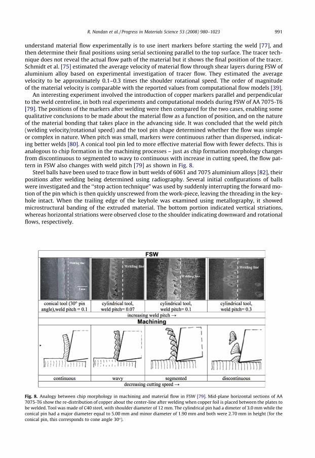
An interesting experiment involved the introduction of copper markers parallel and perpendicularto the weld centreline, in both real experiments and computational models during FSW of AA 7075-T6[79]. The positions of the markers after welding were then compared for the two cases, enabling somequalitative conclusions to be made about the material flow as a function of position, and on the natureof the material bonding that takes place in the advancing side. It was concluded that the weld pitch(welding velocity/rotational speed) and the tool pin shape determined whether the flow was simpleor complex in nature. When pitch was small, markers were continuous rather than dispersed, indicat-ing better welds [80]. A conical tool pin led to more effective material flow with fewer defects. This isanalogous to chip formation in the machining processes – just as chip formation morphology changesfrom discontinuous to segmented to wavy to continuous with increase in cutting speed, the flow pat-tern in FSW also changes with weld pitch [79] as shown in Fig. 8.
Steel balls have been used to trace flow in butt welds of 6061 and 7075 aluminium alloys [82], theirpositions after welding being determined using radiography. Several initial configurations of ballswere investigated and the ‘‘stop action technique” was used by suddenly interrupting the forward mo-tion of the pin which is then quickly unscrewed from the work-piece, leaving the threading in the key-hole intact. When the trailing edge of the keyhole was examined using metallography, it showedmicrostructural banding of the extruded material. The bottom portion indicated vertical striations,whereas horizontal striations were observed close to the shoulder indicating downward and rotationalflows, respectively.
Fig. 8. Analogy between chip morphology in machining and material flow in FSW [79]. Mid-plane horizontal sections of AA7075-T6 show the re-distribution of copper about the center-line after welding when copper foil is placed between the plates tobe welded. Tool was made of C40 steel, with shoulder diameter of 12 mm. The cylindrical pin had a dimeter of 3.0 mm while theconical pin had a major diameter equal to 5.00 mm and minor diameter of 1.90 mm and both were 2.70 mm in height (for theconical pin, this corresponds to cone angle 30�).

992 R. Nandan et al. / Progress in Materials Science 53 (2008) 980–1023
Some idea about the flow of materials can be obtained when microscopic observations are com-bined with knowledge of the crystallographic texture and microtexture [83]. Far from the tool, theundeformed grains have low-angle boundaries while near the tool, elongated subgrains form becauseof the rotation induced by the tool. These subgrains eventually develop high-angle (P15�) grainboundaries [84]. Orientation imaging microscopy can provide shear texture maps which, in turn, givesan idea of the strength of flow.
Macrostructural observations of transverse cross-sections of FS-welded aluminium alloy speci-mens reveals ‘‘onion-ring” shaped structures of the type illustrated in Fig. 9. These have been linkedto the nature of material flow during FSW [85,86,81], but the detailed mechanism of pattern formationis not completely understood. The pattern has been attributed to the geometry of the extrusion ofcylindrical sheets of material during each rotation of the tool [86]. Measurement of the spacing ofthe markings has been found to be equal to the weld pitch, i.e., the length the tool moves forwardin one rotation. Electron back scattered diffraction studies indicate that the bands have different den-sities of second-phase particles, rather than any significant difference in the local grain structure ortexture [87,88]. This is confirmed by studies of crack propagation in FS-welds [89], where it is ob-served that cracks deflect around the onion-ring structure, consistent with local variations in hard-ness. In AA 2024-T351 rolled sheet, segregated banded microstructure consisting of alternatinghard particle-rich and hard particle-poor regions form with the crack path tending to follow regionsof high particle density [90].
In FSW of dissimilar aluminium alloys of cast A356 and wrought 6061, onion-ring patterns consistof lamellar mixture of the two alloys of equal width [91]. When AA 2024 and AA 6061 are welded, theintercalated flow pattern can be visualized by differential etching of the AA 2024 producing contrastrelative to AA 6061 [92–94]. Apart from welding parameters, the base metal microstructure also af-fects the rings. For example, direct-chill casting of AA 5182 produces a dense and uniformly distrib-uted intermetallic particle structure while during strip casting intermetallics are broken-up duringhot rolling and distributed along the primary grain boundaries [95]. Strip-cast base material, withintermetallic particles present in bands, show a definite onion-ring structure in the weld. In contrast,the diffuse rings appear in the weld when the starting material is homogeneous [96].
As a result of recent research, several important features of material flow during FSW are now wellunderstood. The flow path of the plasticized materials across both the advancing and the retreatingsides of the tool and the process of joining is now better understood. However, recent research has alsouncovered several complexities and special features of the material flow in FSW such as the lack ofmixing of the plasticized materials in atomic scale and the formation of certain interesting patternsthat still require further work.
Fig. 9. Optical image showing the macroscopic features [81] in a transverse section of a friction-stir welded 2195-T81 Al–Li–Cualloy. Note the onion-ring and the adjacent large upward movement of material.

R. Nandan et al. / Progress in Materials Science 53 (2008) 980–1023 993
2.4. Temperature fields and cooling rates
The welding variables and the material properties affect the temperature profiles, cooling rates,microstructure and the resulting properties of the welded joint. The temperature fields in FSW exhibitcertain special features. The peak temperatures are significantly lower than those attained in conven-tional fusion welding processes. Furthermore, diffuse heat source in the FSW process and relativelylow welding speed often results in low cooling rate in FSW.
Thermal cycles in FSW can be measured using thermocouples (Fig. 10) [97] and in situ neutron-dif-fraction (Fig. 11) [98] where measured lattice-distortion is related to change in temperature. Whenexperimental data are not available, a recourse is to estimate the temperature profiles and the coolingrates using a computational model after the model has been properly validated with experiments.
Fig. 10. 3D plot of thermal cycles at the bottom surface along the weld centerline of AA 6061-T6 [97]. The thermal cycle at thefront is for the location where tool pin is inserted into the work-piece while other thermal cycles correspond to locations alongthe weld centreline in the direction of tool movement.
Fig. 11. Instantaneous temperature distribution, measured using neutron-diffraction, on the top surface along the weldcenterline behind the the tool pin, for FSW of AA 6061-T6 [98].
994 R. Nandan et al. / Progress in Materials Science 53 (2008) 980–1023
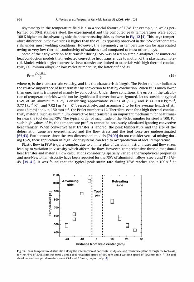
Asymmetry in the temperature field is also a special feature of FSW. For example, in welds per-formed on 304L stainless steel, the experimental and the computed peak temperatures were about100 K higher on the advancing side than the retreating side, as shown in Fig. 12 [4]. This large temper-ature difference in the two sides is higher than the values typically observed in the FSW of other mate-rials under most welding conditions. However, the asymmetry in temperature can be appreciatedowing to very low thermal conductivity of stainless steel compared to most other alloys.
Some of the early work on heat transfer during FSW was based on simple analytical or numericalheat conduction models that neglected convective heat transfer due to motion of the plasticised mate-rial. Models which neglect convective heat transfer are limited to materials with high thermal conduc-tivity (aluminum alloys) or low Péclet number, Pe, the latter defined as
Fig. 12.for theshoulde
Pe ¼ qCpucLk
ð19Þ
where uc is the characteristic velocity, and L is the characteristic length. The Péclet number indicatesthe relative importance of heat transfer by convection to that by conduction. When Pe is much lowerthan one, heat is transported mainly by conduction. Under these conditions, the errors in the calcula-tion of temperature fields would not be significant if convection were ignored. Let us consider a typicalFSW of an aluminium alloy. Considering approximate values of q, Cp and k as 2700 kg m�3,3:77 J kg�1 K�1 and 7:02 J m�1 s�1 K�1, respectively, and assuming L to be the average length of stirzone (6 mm) and u ’ 150 mm s�1, the Péclet number is 12. Therefore, even for a high thermal conduc-tivity material such as aluminium, convective heat transfer is an important mechanism for heat trans-fer near the tool during FSW. The typical order of magnitude of the Péclet number for steel is 100. Forsuch high values of Pe, the temperature profiles cannot be accurately calculated ignoring convectiveheat transfer. When convective heat transfer is ignored, the peak temperature and the size of thedeformation zone are overestimated and the flow stress and the tool force are underestimated[65,43]. Furthermore, since the two-dimensional models [74,99] do not consider vertical mixing dur-ing FSW, their application in high Péclet systems can lead to overprediction of local temperature.
Plastic flow in FSW is quite complex due to an interplay of variation in strain rates and flow stressleading to variation in viscosity which affects the flow. However, comprehensive three-dimensionalheat transfer and material flow calculations considering spatially variable thermophysical propertiesand non-Newtonian viscosity have been reported for the FSW of aluminium alloys, steels and Ti–6Al–4V [39–41]. It was found that the typical peak strain rate during FSW reaches about 100 s�1 at
Peak temperature distribution along the intersection of horizontal midplane and transverse plane through the tool-axis,FSW of 304L stainless steel using a tool rotational speed of 600 rpm and a welding speed of 10.2 mm min�1. The toolr and tool pin diameters were 25.4 and 5.6 mm, respectively [4].
R. Nandan et al. / Progress in Materials Science 53 (2008) 980–1023 995
locations where the velocity gradient is highest, such as near the shoulder edge at the work-piece sur-face and at the pin surface at lower elevations. The strain rate drops sharply to about 30 s�1 a few mmbelow the top surface. The strain rate decreases rapidly with depth due to a significant decrease invelocities through viscous dissipation. The computed strain rates were comparable with the 20 s�1 va-lue estimated based on measured grain-size and calculated peak temperature from a thermal modelreported by Frigaard et al. [9].
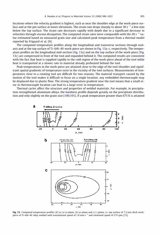
The computed temperature profiles along the longitudinal and transverse sections through tool-axis and at the top surface of Ti–6Al–4V work-piece are shown in Fig. 13a–c, respectively. The temper-ature profiles on the longitudinal mid-section (Fig. 13a) and on the top surface of the work-piece (Fig.13c) are compressed in front of the tool and expanded behind it. The computed results are consistentwith the fact that heat is supplied rapidly to the cold region of the work-piece ahead of the tool whileheat is transported at a slower rate to material already preheated behind the tool.
Peak temperatures in the work-piece are attained close to the edge of the tool shoulder and signif-icant spatial gradients of temperature exist in the vicinity of the tool surfaces. Measurements of tem-peratures close to a rotating tool are difficult for two reasons. The material transport caused by themotion of the tool makes it difficult to focus on a single location; any embedded thermocouple maybe displaced due to plastic flow. The strong temperature gradient near the tool means that a small er-ror in thermocouple location can lead to a large error in temperature.
Thermal cycles affect the structure and properties of welded materials. For example, in precipita-tion-strengthened aluminum alloys, the hardness profile depends greatly on the precipitate distribu-tion and only slightly on the grain-size [100,101]. If a peak temperature greater than 675 K is attained
Fig. 13. Computed temperature profiles (K) in (a) xz-plane, (b) yz-plane and (c) z-plane, i.e. top surface of 7.2 mm thick work-piece of Ti–6Al–4V alloy welded with translational speed of 1.6 mm s�1 and rotational speed of 275 rpm [72].

996 R. Nandan et al. / Progress in Materials Science 53 (2008) 980–1023
at any location, complete dissolution and re-precipitation takes place there. The dissolution andgrowth of the precipitates during the welding thermal cycle may lead to softening. Even when thepeak temperature is lower than 675 K, the density of the strengthening precipitate reduces as the peaktemperature gets closer to 675 K [100].
Dimensional analysis, a useful tool for understanding a complex situation, can be used to estimatepeak temperature in the work-piece using available numerically computed and experimentally mea-sured thermal cycles for different alloys [102]. The non-dimensional peak temperature, T�, and heatinput, Q �, are given by
T� ¼ TP � Ta
TS � Taand Q � ¼ fr8AxCp
kU2 ð20Þ
where Ta, and TS are the peak, ambient and solidus temperatures of the work-piece, respectively, frepresents the fraction of heat that is transported into the work-piece, r8 is the yield strength valueat a temperature which is 0.8 times the solidus temperature and A is the surface area of the shoulder.The thermal properties at the mean temperature, defined as ðTS þ TaÞ=2, are used in the calculations.Note that the non-dimensional heat input, Q �, is similar to a recovery factor, or the ratio of actual totheoretical temperature recovery [103] for surface of a body undergoing adiabatic viscous heating:
Q � ¼ fr8Axk|fflfflffl{zfflfflffl}
actual
,U2
Cp|{z}theoretical
ð21Þ
A correlation between dimensionless peak temperature, T�, and dimensionless heat input, Q �, valid fora range of Q � between 5� 103 and 5� 105, is obtained from experimentally measured and computedresults (Fig. 14):
T� ¼ 0:131 logðQ �Þ þ 0:196 ð22Þ
In principle, the yield stress of the material drops dramatically as the solidus temperature isapproached. If the yield stress decreases, so does the rate of heat generation, reaching zero in the lim-iting case of melting. The decrease in temperature allows the material to recover it strength, thus per-mitting a steady temperature to be established below the solidus [104]. However, in practice it ispossible that localised melting can occur under non-steady conditions. The unsteady condition is
log (Q*)
T*
4 4.5 5 5.50
0.2
0.4
0.6
0.8
1
linear fit6061 aluminum alloy1018 C-Mn steel304 stainless steelreported-aluminum alloyreported-1018 steelreported-304 steel
T* = 0.131 log (Q*) + 0.196
standard deviation = 0.05510
10
Fig. 14. Variation of dimensionless peak temperature [102] with non-dimensional heat input.

R. Nandan et al. / Progress in Materials Science 53 (2008) 980–1023 997
possible because heat generation is instantaneous while heat transfer takes time. Incipient meltinghas been reported in the nugget zone at high travel speeds in an aluminium alloy (AA 7100) [105],and locally melted films were observed during the FSW of cast magnesium alloy AZ91 [106].
Cooling rate determines the precipitation sequence in age hardenable alloys. It also affects thegrain-size. In fact, friction-stir processing, combined with large cooling rates obtained at higher rota-tional speed, has been found to be useful for grain refinement and has been suggested as a techniquefor producing bulk nano-crystalline materials [107].
In high carbon steels, for example S70C (0.72 wt.% C), FSW can result in martensite formation [108].To keep the volume fraction of martensite low, either the peak temperature should be lower than A1
critical temperature or the cooling rate should be slower than the critical cooling rate. The peak tem-perature decreases with increase in welding speed or decrease in rotational speed. The cooling ratedecreases with decrease in welding speed and with decrease in peak temperature. Low welding speedcombined with low rotational speed produce slow cooling rate and prevent martensite formation[109].
2.5. Welding variables
The welding speed, the tool rotational speed, the vertical pressure on the tool, the tilt angle of thetool and the tool design are the main independent variables that are used to control the FSW process.The heat generation rate, temperature field, cooling rate, x-direction force, torque, and the power de-pend on these variables. The effects of several of the independent variables on the peak temperaturehave been discussed in the previous section. In short, peak temperature increases with increasingrotational speed and decreases slightly with welding speed. Peak temperature also increases with in-crease in the axial pressure. Fig. 15 shows significant increase in peak temperature with increase inrotational speed.
During FSW, the torque depends on several variables such as the applied vertical pressure, tool de-sign, the tilt angle, local shear stress at the tool material interface, the friction coefficient and the ex-tent of slip between the tool and the material. Measured torque values can provide some idea aboutthe average flow stress near the tool and the extent of slip between the tool and the work-piece forcertain conditions of welding, when other variables are kept constant.
The torque decreases with increase in the tool rotation speed due to increase in the heat generationrate and temperature when other variables are kept constant. It becomes easier for the material toflow at high temperatures and strain rates. However, torque is not significantly affected by the changein welding speed as shown in Fig. 16. The relative velocity between the tool and the material is influ-enced mainly by the rotational speed. Therefore, the heat generation rate is not significantly affectedby the welding speed. High traverse speeds tend to reduce heat input and temperatures. The torque
Fig. 15. Relationship between rotational speed and peak temperature in FS-welds of AA 6063 [110].
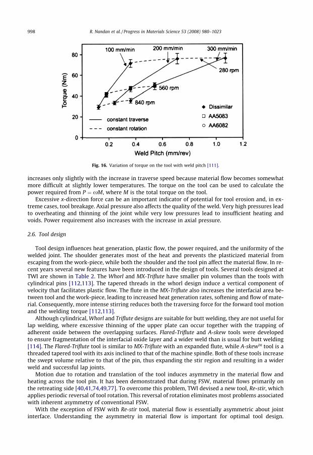
Fig. 16. Variation of torque on the tool with weld pitch [111].
998 R. Nandan et al. / Progress in Materials Science 53 (2008) 980–1023
increases only slightly with the increase in traverse speed because material flow becomes somewhatmore difficult at slightly lower temperatures. The torque on the tool can be used to calculate thepower required from P ¼ xM, where M is the total torque on the tool.
Excessive x-direction force can be an important indicator of potential for tool erosion and, in ex-treme cases, tool breakage. Axial pressure also affects the quality of the weld. Very high pressures leadto overheating and thinning of the joint while very low pressures lead to insufficient heating andvoids. Power requirement also increases with the increase in axial pressure.
2.6. Tool design
Tool design influences heat generation, plastic flow, the power required, and the uniformity of thewelded joint. The shoulder generates most of the heat and prevents the plasticized material fromescaping from the work-piece, while both the shoulder and the tool pin affect the material flow. In re-cent years several new features have been introduced in the design of tools. Several tools designed atTWI are shown in Table 2. The Whorl and MX-Triflute have smaller pin volumes than the tools withcylindrical pins [112,113]. The tapered threads in the whorl design induce a vertical component ofvelocity that facilitates plastic flow. The flute in the MX-Triflute also increases the interfacial area be-tween tool and the work-piece, leading to increased heat generation rates, softening and flow of mate-rial. Consequently, more intense stirring reduces both the traversing force for the forward tool motionand the welding torque [112,113].
Although cylindrical, Whorl and Triflute designs are suitable for butt welding, they are not useful forlap welding, where excessive thinning of the upper plate can occur together with the trapping ofadherent oxide between the overlapping surfaces. Flared-Triflute and A-skew tools were developedto ensure fragmentation of the interfacial oxide layer and a wider weld than is usual for butt welding[114]. The Flared-Triflute tool is similar to MX-Triflute with an expanded flute, while A-skewTM tool is athreaded tapered tool with its axis inclined to that of the machine spindle. Both of these tools increasethe swept volume relative to that of the pin, thus expanding the stir region and resulting in a widerweld and successful lap joints.
Motion due to rotation and translation of the tool induces asymmetry in the material flow andheating across the tool pin. It has been demonstrated that during FSW, material flows primarily onthe retreating side [40,41,74,49,77]. To overcome this problem, TWI devised a new tool, Re-stir, whichapplies periodic reversal of tool rotation. This reversal of rotation eliminates most problems associatedwith inherent asymmetry of conventional FSW.
With the exception of FSW with Re-stir tool, material flow is essentially asymmetric about jointinterface. Understanding the asymmetry in material flow is important for optimal tool design.

Table 2A selection of tools designed at TWI [112,16]
Tool Cylindrical WhorlTM MX trifluteTM Flared trifluteTM A-skewTM Re-stirTM
Schematics
Tool pin shape Cylindricalwith threads
Tapered withthreads
Threaded,tapered withthree flutes
Tri-flute withflute endsflared out
Inclinedcylindrical withthreads
Tapered withthreads
Ratio of pinvolume tocylindricalpin volume
1 0.4 0.3 0.3 1 0.4
Swept volumeto pinvolumeratio
1.1 1.8 2.6 2.6 Depends on pinangle
1.8
Rotary reversal No No No No No YesApplication Butt welding;
fails in lapwelding
Butt weldingwith lowerweldingtorque
Butt weldingwith furtherlower weldingtorque
Lap weldingwith lowerthinning ofupper plate
Lap weldingwith lowerthinning ofupper plate
When minimumasymmetry inweld property isdesired
R. Nandan et al. / Progress in Materials Science 53 (2008) 980–1023 999
Colegrove and Shercliff [44,47] calculated material flow for the FSW of AA 7075 using computationalfluid dynamics. They compared the mechanical efficiency of a triangular tool with convex surfaces(Trivex) with that of a conventional tool (Triflute) by examining the streamlines around these tools.They suggested that the Triflute tool produced a strong auguring action, thus increasing the downwardforce (Fig. 17).
Zhao et al. [115] studied the effect of tool pin design on the weldability and mechanical propertiesof welded 2014 Al plates. Cylindrical and tapered tool pins did not ensure effective mixing in the ver-tical direction leading to wormholes at the base of the TMAZ. However, when tapered tools withthreads were used, defect free welds were obtained. Other studies have also confirmed that tools withscrew threads generate more heat and improve flow of the softer material by exerting a downwardforce. Since the material flows mainly on the retreating side, insufficient plasticity and material flowresults in a ‘‘wormhole” on the advancing side [36,76]. This effect becomes more prominent at lowtemperatures due to sluggish flow of materials. The choice of pin angle, which is the angle betweenthe conical surface of the pin and its axis, is another important parameter which influences theFSW process; increasing the angle leads to a more uniform temperature distribution along the verticaldirection, which helps in reducing distortion [68]. An angle of ’40� is thought to be optimum for 7xxxaluminium alloys [68].
Design of tools based on a quantitative understanding of material flow is just beginning. Cole-grove and Shercliff [44,47] used a thermal model based on FLUENT to design a tool to minimisethe traversing force during FSW of aluminium alloy. They examined several tool geometries includ-ing Trivex, which is triangular in shape with convex surfaces, and MX-Trivex which had similar shapewith threads. They observed that the traversing force and downward forces were considerably lowerfor the Trivex tools relative to those for Triflute, especially at lower applied shear stress where con-siderable slip occurs between the tool and the work-piece. They suggested that Trivex with its con-vex surfaces avoids sticking to the material that reduces the shear force at the tool–metal interfaceand consequently reduces the traversing force. Triflute, on the other hand, has features that impedeflow and the tool sticks to the material even at low applied shear stress. The entrapped material inthe tool leads to a large shearing effect causing correspondingly greater tool forces. Interestingly,
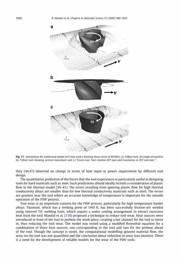
Fig. 17. Streamlines for isothermal model [47] that used a limiting shear stress of 40 MPa: (a) Triflute tool, (b) single streamlinefor Triflute tool showing vertical movement and (c) Trivex tool. Tool rotation 457 rpm and translation at 457 mm min�1.
1000 R. Nandan et al. / Progress in Materials Science 53 (2008) 980–1023
they [44,47] observed no change in terms of heat input or power requirement by different tooldesign.
The quantitative prediction of the forces that the tool experiences is particularly useful in designingtools for hard materials such as steel. Such predictions should ideally include a consideration of plasticflow in the thermal model [39–41]. The errors resulting from ignoring plastic flow for high thermalconductivity alloys are smaller than for low thermal conductivity materials such as steel. The errorsare greatest near the tool where an accurate knowledge of temperature is important for the smoothoperation of the FSW process.
Tool wear is an important concern for the FSW process, particularly for high temperature harderalloys. Titanium, which has a melting point of 1941 K, has been successfully friction-stir weldedusing sintered TiC welding tools, which require a water cooling arrangement to extract excessiveheat from the tool. Mandal et al. [116] proposed a technique to reduce tool wear. Heat sources wereintroduced in front of the tool to preheat the work-piece, creating a hot channel for the tool to movein, thus reducing the tool wear. The model was tested using a modified Rosenthal equation for acombination of three heat sources, one corresponding to the tool and two for the preheat aheadof the tool. Though the concept is novel, the computational modelling ignored material flow, thewear on the tool was not quantified and the conclusion about reduction in wear was intuitive. Thereis a need for the development of reliable models for the wear of the FSW tools.

R. Nandan et al. / Progress in Materials Science 53 (2008) 980–1023 1001
2.7. Defects
Common defects in friction-stir welds include porosity and surface defects. At a constant rotationalspeed, an increase in the travel speed leads to wormhole initiation near the bottom of the weld. Fur-thermore, the size of the wormholes increases with the travel speed [117] because of inadequatematerial flow towards the bottom of the weld. There are indications that the travel speed to rotationalspeed ratio is an important variable in the formation of the wormhole defect [118]. For the same mate-rial and tool geometry, a high ratio tends to favour the formation of wormhole defects [119].
Most of the heat generation occurs at the interface between the tool shoulder and the work-piece.Significant heterogeneity in heat generation at that interface can lead to defect formation in the formof excess flash due to surface overheating [117,120].
The propensity for cracks or voids increases with the welding speed although there is an alloy-dependence [121]. For example, defects dominated in AA 5083-O and AA 2024-T3 but not in AA6063-T6 in which there is a significant drop in hardness within the TMAZ. The defects tend to occuron the advancing side where an abrupt microstructural transition occurs from the highly refined nug-get zone to the TMAZ while the transition was gradual on the relatively defect free retreating side.
Cast Al–12 wt.% Si alloys contain coarse particles of silicon which can be used to reveal the flow anddefect evolution during FSW [122]. Insufficient heating causes the brittle Si particles to crumble sothat the observation of fine Si particles after FSW is indicative of defect formation due to limited mate-rial flow. Therefore, it is not surprising that finer particles were detected on the advancing side nearthe bottom of the tool pin where inadequate flow is associated with void formation.
It has been suggested that the force on the tool in the x-direction, which can be measured using adynamometer, could be used to predict defect formation in FSW on the assumption that large forcesindicate sluggish flow [123]. Maps showing the fraction of stirred material which is at a given flowstress and temperature, with superimposed strain rate contours (Fig. 18) can also indicate the ten-dency for defect generation [124]. Referring to Fig. 18, at 80 rpm a greater amount of material is beingdeformed at a higher strain rate with both the Triflat and Trivex tools than with the cylindrical tool. At200 rpm, greater amount of material was deformed at moderate temperatures (725–735 K) and strainrates (1–50 s�1) with the Trivex tool which shows largest deformation domain. It was concluded [124]that optimum welds correspond to maps with large regions of moderate to high strain rates and tem-peratures 30–50 K below the solidus temperature. Higher temperatures will lead to softening of thematerial and reduce the size of the deformation region.
Tool design and welding variables affect materials flow patterns. However, no specific character ofthe material flow has been related with the porosity formation and no unified mechanism of porosityformation exists.
Elangovan et al. [125] examined the effects of rotational speed and tool pin design on defect for-mation in friction-stir processing of AA 2219. Five pin profiles (straight cylindrical, tapered cylindrical,threaded cylindrical, triangular and square) were used to fabricate joints at various tool rotationalspeeds. The square tool pin profile produced the least defect content in the weld as the flat faces pro-duced a pulsating action which led to more effective stirring. Also, a square tool has higher eccentricitywhich is defined as the ratio of the dynamic volume swept by the tool to the static volume of the tool.For example, a square tool has eccentricity of pd2
=4 : d2=2 ¼ p=2 � 1:57 where d is the diagonal of the
square.In FSW lap joints of AA5083 and SS400, the size of the voids formed along the weld interface in-
creases with increase in diameter of the tool pin and tool tilt angle [126]. Large diameter pin produces(>5 mm) more heat and forms intermetallic compound FeAl3 and Fe2Al5 instead of FeAl formed at low-er temperature. Aluminum rich FeAl3 and Fe2Al5 are harder and more brittle than FeAl and they reducejoint shear strength. Increasing the tool tilt angle (>1�) also increases the heat generation rate, formsaluminum rich precipitates and decreases joint strength [126].
One advantage of the FEM model [36] is its ability to predict void formation because the arbitrary-Langrangian–Eulerian formulation allows for large material deformation and for the grid to track thematerial so that separation can occur between the work-piece and tool. Fig. 19 shows void formationat the lower advancing side, near the trailing edge of the pin/work-piece interface, due to incompletedeposition of plastic material.

Fig. 18. Material condition maps for (a) Triflat, (b) Trivex and (c) cylindrical tool pin at 80 and 200 rpm [124].
Fig. 19. Void formation at the lower advancing side due to incomplete filling [36] modeled using ALE formulation of FEM.Temperature contours are shown in �C.
1002 R. Nandan et al. / Progress in Materials Science 53 (2008) 980–1023
R. Nandan et al. / Progress in Materials Science 53 (2008) 980–1023 1003
2.8. Residual stress
The presence of residual stress in a weld plate affects its distortion behaviour and ability to sustainapplied loads while maintaining structural integrity [127–129]. While compressive stresses can insome circumstances be beneficial [130], tensile stresses can cause crack initiation and aid its propa-gation leading to catastrophic failure.
Residual stresses in the weld can be measured by using: (1) diffraction studies using X-ray or neu-tron sources without destroying the weld and (2) destructive hole-drilling methods [127,128,131].Since diffraction is expensive and conventional hole-drilling is only suited to uniform plane stressaround the hole, Ya et al. [132] used Moiré interferometry incremental-hole-drilling method to assessresidual stress in a friction-stir weld. Synchrotron diffraction has also been used to measure residualstress in such welds in the context of fatigue behaviour [133].
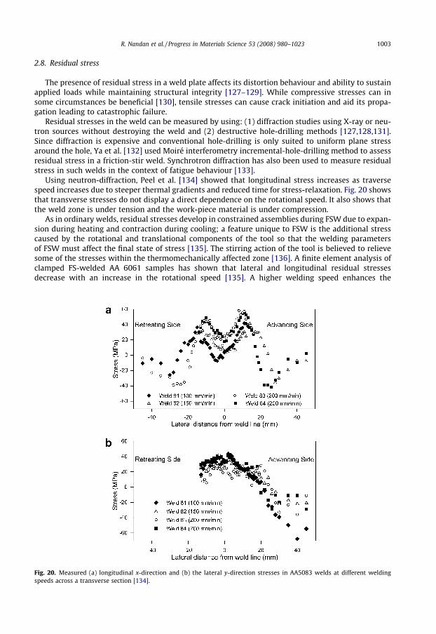
Using neutron-diffraction, Peel et al. [134] showed that longitudinal stress increases as traversespeed increases due to steeper thermal gradients and reduced time for stress-relaxation. Fig. 20 showsthat transverse stresses do not display a direct dependence on the rotational speed. It also shows thatthe weld zone is under tension and the work-piece material is under compression.
As in ordinary welds, residual stresses develop in constrained assemblies during FSW due to expan-sion during heating and contraction during cooling; a feature unique to FSW is the additional stresscaused by the rotational and translational components of the tool so that the welding parametersof FSW must affect the final state of stress [135]. The stirring action of the tool is believed to relievesome of the stresses within the thermomechanically affected zone [136]. A finite element analysis ofclamped FS-welded AA 6061 samples has shown that lateral and longitudinal residual stressesdecrease with an increase in the rotational speed [135]. A higher welding speed enhances the
Fig. 20. Measured (a) longitudinal x-direction and (b) the lateral y-direction stresses in AA5083 welds at different weldingspeeds across a transverse section [134].
1004 R. Nandan et al. / Progress in Materials Science 53 (2008) 980–1023
longitudinal residual stress but reduces it along the lateral direction. The analysis also showed that themaximum temperature gradients in the sample are located just beyond the edge of the tool shoulder.As might be expected, the residual stress distribution is dramatically altered on unclamping the sam-ples after friction-stir welding and this must be taken into account in any modeling effort.
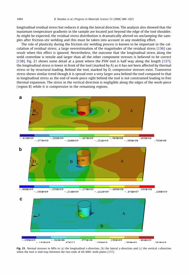
The role of plasticity during the friction-stir welding process is known to be important in the cal-culation of residual stress; a large overestimation of the magnitudes of the residual stress [136] canresult when this effect is ignored. Nevertheless, the outcome that the longitudinal stress along theweld centreline is tensile and larger than all the other component stresses is believed to be correct[138]. Fig. 21 shows some detail at a point where the FSW tool is half way along the length [137];the longitudinal stress is lower in front of the tool (marked by A) as it has not been affected by thermalstress or by structural loading. Behind the tool, marked by D, compressive stresses exist. Transversestress shows similar trend though it is spread over a very larger area behind the tool compared to thatin longitudinal stress as the end of work-piece right behind the tool is not constrained leading to freethermal expansion. The stress in the vertical direction is negligible along the edges of the work-piece(region B) while it is compressive in the remaining regions.
Fig. 21. Normal stresses in MPa in (a) the longitudinal x-direction, (b) the lateral y-direction and (c) the vertical z-directionwhen the tool is mid-way between the two ends of AA 6061 weld plates [137].
R. Nandan et al. / Progress in Materials Science 53 (2008) 980–1023 1005
Tensile stresses present in FS-welded samples lead to poor mechanical properties. Applying exter-nal tensioning during welding [139] induces compressive stresses which have the benefit of inhibitingcrack propagation. Models predict that increasing tensioning levels to values higher than 50% of theroom temperature yield stress in AA2024 aluminium alloys, leads to tension in the weld being re-placed by desirable compressive stresses [140]. This is an important finding and can be used by weld-ers as a guiding principle to produce high-quality welds. Not surprisingly, crack propagation rates areknown to correlate strongly with the state of stress [141].
There has been systematic work on the resistance to fatigue of friction-stir welds in aluminium andtitanium alloys [142], which demonstrates the key role of residual stresses in controlling crack growthwithin the HAZ along the welding direction [143]. Although the levels of residual stress can be smallerthan in conventional welding scenarios, they have a large effect on near-threshold crack propagationrates. In AA 7050-T7451, fatigue crack propagation in the weld nugget is inferior, while it is superior tothat of base alloy in the HAZ [143]. In HAZ, compressive residual stresses dominate crack growth[144]. For the weld nugget region, microstructure and intergranular failure mechanism dominatecrack growth. In precipitation hardened aluminium alloys the particles in the HAZ are much coarserand less coherent than the base material. This should in general reduce the fatigue crack growth ratein the HAZ relative to the base material, but only if tensile residual stresses are not present within theHAZ [142]. Post-weld solution heat-treatment and aging also restores the strengths of the nugget tothe same level as the base material [83]. In AA 7050 grain boundaries are sensitized during FSW[145], leading to intergranular fracture when fatigued in a 3.5% NaCl solution.
3. Microstructure and properties of friction-stir welded alloys
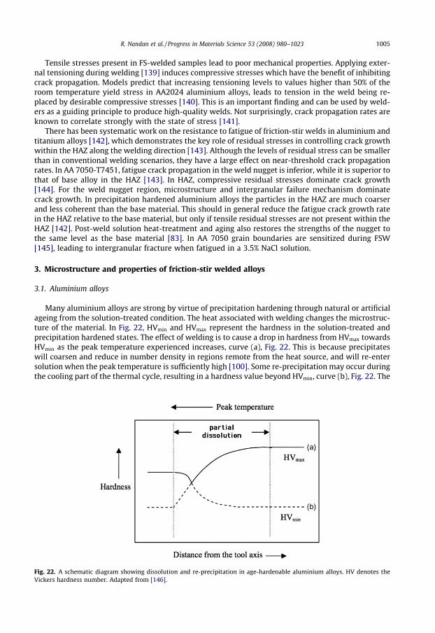
3.1. Aluminium alloys
Many aluminium alloys are strong by virtue of precipitation hardening through natural or artificialageing from the solution-treated condition. The heat associated with welding changes the microstruc-ture of the material. In Fig. 22, HVmin and HVmax represent the hardness in the solution-treated andprecipitation hardened states. The effect of welding is to cause a drop in hardness from HVmax towardsHVmin as the peak temperature experienced increases, curve (a), Fig. 22. This is because precipitateswill coarsen and reduce in number density in regions remote from the heat source, and will re-entersolution when the peak temperature is sufficiently high [100]. Some re-precipitation may occur duringthe cooling part of the thermal cycle, resulting in a hardness value beyond HVmin, curve (b), Fig. 22. The
Fig. 22. A schematic diagram showing dissolution and re-precipitation in age-hardenable aluminium alloys. HV denotes theVickers hardness number. Adapted from [146].

1006 R. Nandan et al. / Progress in Materials Science 53 (2008) 980–1023
ultimate result is the continuous line with a minimum in hardness somewhere in the heat-affectedzone, due to the competing effects of dissolution and re-precipitation [146]. But in contrast to agehardenable AA 6082, where a minimum hardness occurs in the HAZ, FSW of non-hardenable AA5082 results in uniform hardness across the weld [147].
This general scenario may be complicated by the effects of deformation in FSW as described for thespecific example of AA 2219. AA 2219 is a copper precipitation-strengthened alloy containing about6.3 wt.% Cu, which because of its strength and toughness at low temperatures, is used for containingliquefied gases for rockets of various kinds. It is frequently supplied in the T87 condition, meaning thatit has been solution-treated, cold-worked (10% reduction in rolling) and artificially aged. It can bewelded using arc processes but this results in a reduction in the cross-weld strength because the proofstrength of the fusion zone decreases to about 140 MPa compared with the 370 MPa of the plate [148].The former can be increased to between 220 and 275 MPa using pulsed GTAW or pulsed electronbeam welding techniques because this promotes finer grains in the fusion zone [148].
Friction-stir welding does not seem to have an advantage over arc welding with respect to thestrength of the fusion zone, as illustrated in Fig. 23. Notice that the TMAZ is somewhat softer thanthe fusion zone because the latter dynamically recrystallises into a fine grain structure. It is the coars-ening of the Al2Cu precipitates in the TMAZ that is partly responsible for its softening [150]. Sometransmission electron micrographs across the weld are illustrated in Fig. 24; these show clearly thehuge changes due to the heat from the process. The formation of coarse precipitates at the grainboundaries, and their associated precipitate-free zones, are common detrimental features in themicrostructure.
The fact that FSW welds in precipitation hardened alloys lead to a weak zone is not surprising giventhat the majority of strengthening in most strong alloys comes from precipitates [151]. There is someevidence that manipulation of pin profiles and FSW parameters may help improve slightly, the hard-ness in the central region [125] or indeed, in the HAZ [152]. Theoretical work has also been done to seeif cryogenic cooling after the tool pass can help retain alloying elements in solution after the peak tem-perature is experienced, so that the alloy can then naturally age and not develop the coarsened micro-structures typical of slow cooling from the peak temperature [153]. However, computations indicatethat the advantage in so doing is likely to be minimal [153].
Fig. 25a shows that the grain-size increases with increase in peak temperature caused by increasein rotational speed. Here grain-size is related to peak temperature by assuming static grain-growth ofdynamically recrystallised grains, during the cooling of the thermal cycle [110]:
Fig. 23similarIn the l
D2 ¼ D20 þ At eð�Q=RTpÞ ð23Þ
where D0 and D are the initial and recrystallized grain-size, A is a constant, t is the time to cool to448 K, Q is the activation energy for grain-growth, Tp is the peak temperature. Assumption of isother-mal condition leads to over-prediction of grain-sizes [110]. Precipitate free zones form near the grainboundaries because grain boundaries act as sinks for nearby dislocations, reducing nucleation sites for
. Open circles are data from friction-stir weld, plotted relative to the centreline of the FSW for alloy AA2219 [149];data have been reported by Paglia and Buchheit [150]. Filled circles from a variety of arc and electron-beam welds [148].atter case all values are plotted at zero on the horizontal axis to represent the fusion zone.

Fig. 24. Microstructure variations across aluminium alloy AA2219 joined using friction-stir welding. (a) Unaffected parentmaterial in the precipitation hardened condition; (b) the nugget; (c) the heat-affected zone. Micrographs courtesy of Dr.Christian Paglia.
Fig. 25. Relationship between (a) peak temperature and grain-size in AA 6063 [110] and (b) grain-size and volume fraction ofPFZs.
R. Nandan et al. / Progress in Materials Science 53 (2008) 980–1023 1007
precipitates and also as precipitation sites, effectively reducing the solute content around them. Asgrain-size increase, assuming constant width of PFZs, their volume fraction decreases with increasepeak temperature as shown in Fig. 25b [110].
Not all alloys of aluminium are precipitation hardened. In the 2000 series alloys, the strength de-pends more on grain-size (d), which has been expressed in terms of the Zener–Holloman parameter[154]:
log d ¼ aþ b log Z ð24Þ
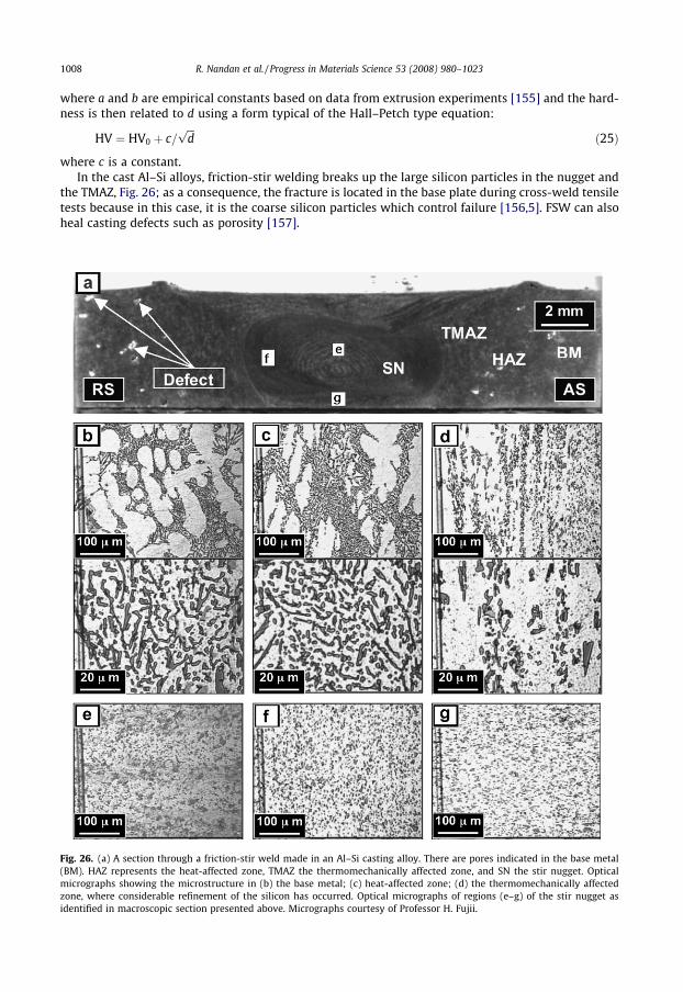
1008 R. Nandan et al. / Progress in Materials Science 53 (2008) 980–1023
where a and b are empirical constants based on data from extrusion experiments [155] and the hard-ness is then related to d using a form typical of the Hall–Petch type equation:
Fig. 26(BM). Hmicrogzone, widentifi
HV ¼ HV0 þ c=ffiffiffidp
ð25Þ
where c is a constant.In the cast Al–Si alloys, friction-stir welding breaks up the large silicon particles in the nugget and
the TMAZ, Fig. 26; as a consequence, the fracture is located in the base plate during cross-weld tensiletests because in this case, it is the coarse silicon particles which control failure [156,5]. FSW can alsoheal casting defects such as porosity [157].
. (a) A section through a friction-stir weld made in an Al–Si casting alloy. There are pores indicated in the base metalAZ represents the heat-affected zone, TMAZ the thermomechanically affected zone, and SN the stir nugget. Optical
raphs showing the microstructure in (b) the base metal; (c) heat-affected zone; (d) the thermomechanically affectedhere considerable refinement of the silicon has occurred. Optical micrographs of regions (e–g) of the stir nugget as
ed in macroscopic section presented above. Micrographs courtesy of Professor H. Fujii.

R. Nandan et al. / Progress in Materials Science 53 (2008) 980–1023 1009
Corrosion studies indicate that the weld zones produced by friction-stir welding have comparableenvironmentally assisted cracking susceptibility as the unaffected parent [150].
3.2. Magnesium alloys
Magnesium alloys, normally produced by casting, may find significant applications in the automo-tive and aerospace industries with rapid growth particularly in die-cast vehicle components becauseof their better mass-equivalent properties [158–161]. They are used for light-weight parts which oper-ate at high speeds. The motivation for using FSW for magnesium alloys is that arc welding results inlarge volumes of non-toxic fumes [162]. On the other hand, solid-state FSW does not result in soluteloss by evaporation or segregation during solidification, resulting in homogeneous distribution of sol-utes in the weld [163]. Also, many magnesium alloys in the cast condition contain porosity which canbe healed during FSW.
The hardness and strength can be retained after friction-stir welding [164]. There is no significantprecipitation hardening in the alloy studied (AZ31, ’Mg–3Al–1Zn wt.% wrought) and the net variationin hardness over the entire joint was within the range 45–65 HV, with the lower value correspondingto the base plate [164–166]. In the same system, a higher starting hardness of 70 HV leads to a sub-stantially lower hardness in the nugget (50–60 HV); the variations in hardness appear to be consistentwith measured variations in grain-size in accordance with the form of the Hall–Petch relationship[165,167]. The grains in both the nugget and TMAZ tend to be in a recrystallised form, and tend tobe finer when the net heat input is smaller (for example at higher welding speeds).
In Mg–Zr alloys with Zr-containing particles, FSW leads to a considerable refinement of the grainstructure and sound welds can be produced in thin sheets over a wide range of welding conditions;for sheets thicker than about 3 mm, the welds contained defects associated with an inability to supplysufficient heat during welding [168]. There are, however, contradictory results [169] showing success-ful welds in 6 mm thick Mg–Zn–Y–Zr plates so it is unlikely that these results are generic to magne-sium alloys.
3.3. Copper alloys
Copper which has much higher thermal diffusivity than steel cannot easily be welded by conven-tional fusion welding techniques. Heat input required for copper is much higher than conventionalFSW because of the greater dissipation of heat through the work-piece. Still, FSW has been success-fully used to weld very thick (50 mm) thick copper canisters for containment of nuclear waste [170].
FSW in copper alloys have all the typical zones found in other materials: the nugget, TMAZ, HAZand base structure. The nugget has equiaxed recrystallised small grains and its hardness may be high-er or lower than the base material depending on the grain-size of the base metal. When 4 mm thickcopper plates with average grain-size of 210 lm were welded at high rpm (1250) and low weldingspeed (1.01 mm s�1) [171], nugget had lower hardness (60–90 HV), compared to base metal (105–110 HV). Even though grain-size decreased from 210 to 100 lm, hardness decreased slightly due toreduction in dislocation density relative to base metal [171]. Similar decrease in dislocation densityin the nugget zone compared to parent metal has been observed for AA 7075 [11] and AA 6061 [12].
On the other hand, when 2 mm thick copper plates with average grain-size of 30 lm were weldedat 1000 rpm and 0.5 mm s�1 low welding speed, nugget (128–136 HV) was harder than the base metal(106–111 HV) due to reduction in average grain-size to 11 lm [172]. Flores et al. have also shown thatas-cast AA 7073 showed that weld nugget was harder than base metal while the 50% cold-rolled alloyshowed reduced hardness in the nugget [173].
3.4. Titanium alloys
By far the most dominant of titanium alloys is Ti–6Al–4V, which in its commercial condition has amixed microstructure consisting of hexagonal-close packed a and body-centred cubic b phases, whichis the stable phase at high temperatures. The usual microstructure is produced by cooling from the aphase field to produce Widmanstätten b with about 50% of the a being retained in the microstructure.
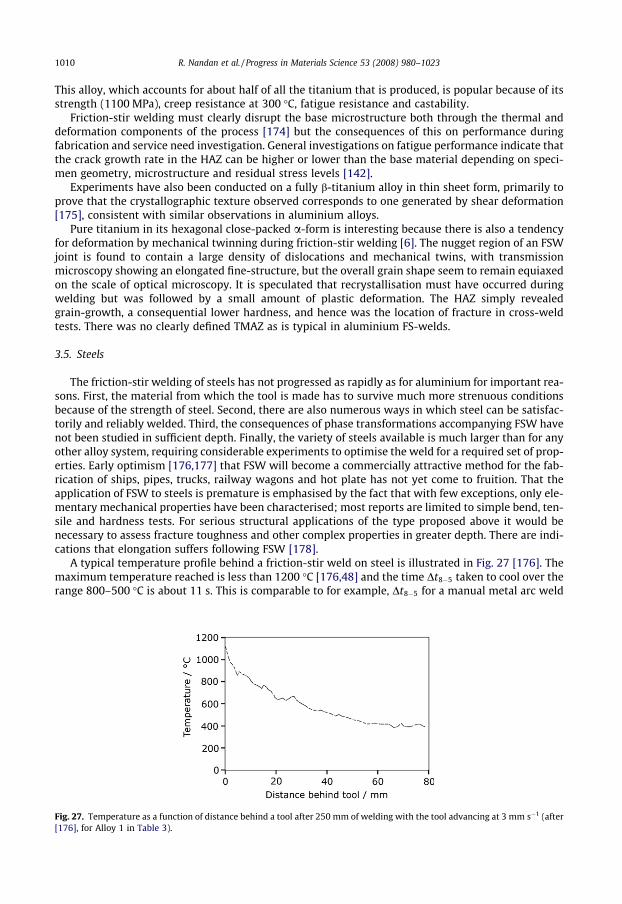
1010 R. Nandan et al. / Progress in Materials Science 53 (2008) 980–1023
This alloy, which accounts for about half of all the titanium that is produced, is popular because of itsstrength (1100 MPa), creep resistance at 300 �C, fatigue resistance and castability.
Friction-stir welding must clearly disrupt the base microstructure both through the thermal anddeformation components of the process [174] but the consequences of this on performance duringfabrication and service need investigation. General investigations on fatigue performance indicate thatthe crack growth rate in the HAZ can be higher or lower than the base material depending on speci-men geometry, microstructure and residual stress levels [142].
Experiments have also been conducted on a fully b-titanium alloy in thin sheet form, primarily toprove that the crystallographic texture observed corresponds to one generated by shear deformation[175], consistent with similar observations in aluminium alloys.
Pure titanium in its hexagonal close-packed a-form is interesting because there is also a tendencyfor deformation by mechanical twinning during friction-stir welding [6]. The nugget region of an FSWjoint is found to contain a large density of dislocations and mechanical twins, with transmissionmicroscopy showing an elongated fine-structure, but the overall grain shape seem to remain equiaxedon the scale of optical microscopy. It is speculated that recrystallisation must have occurred duringwelding but was followed by a small amount of plastic deformation. The HAZ simply revealedgrain-growth, a consequential lower hardness, and hence was the location of fracture in cross-weldtests. There was no clearly defined TMAZ as is typical in aluminium FS-welds.
3.5. Steels
The friction-stir welding of steels has not progressed as rapidly as for aluminium for important rea-sons. First, the material from which the tool is made has to survive much more strenuous conditionsbecause of the strength of steel. Second, there are also numerous ways in which steel can be satisfac-torily and reliably welded. Third, the consequences of phase transformations accompanying FSW havenot been studied in sufficient depth. Finally, the variety of steels available is much larger than for anyother alloy system, requiring considerable experiments to optimise the weld for a required set of prop-erties. Early optimism [176,177] that FSW will become a commercially attractive method for the fab-rication of ships, pipes, trucks, railway wagons and hot plate has not yet come to fruition. That theapplication of FSW to steels is premature is emphasised by the fact that with few exceptions, only ele-mentary mechanical properties have been characterised; most reports are limited to simple bend, ten-sile and hardness tests. For serious structural applications of the type proposed above it would benecessary to assess fracture toughness and other complex properties in greater depth. There are indi-cations that elongation suffers following FSW [178].
A typical temperature profile behind a friction-stir weld on steel is illustrated in Fig. 27 [176]. Themaximum temperature reached is less than 1200 �C [176,48] and the time Dt8�5 taken to cool over therange 800–500 �C is about 11 s. This is comparable to for example, Dt8�5 for a manual metal arc weld
Fig. 27. Temperature as a function of distance behind a tool after 250 mm of welding with the tool advancing at 3 mm s�1 (after[176], for Alloy 1 in Table 3).
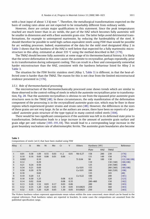
R. Nandan et al. / Progress in Materials Science 53 (2008) 980–1023 1011
with a heat input of about 1.3 kJ mm�1. Therefore, the metallurgical transformations expected on thebasis of cooling rates alone are not expected to be remarkably different from ordinary welds.
However, there are certain major qualifications to this statement. Since the peak temperaturesreached are much lower than in arc welds, the part of the HAZ which becomes fully austenitic willbe smaller in dimension and with a finer austenite grain-size. The latter helps avoid detrimental trans-formations, for example to untempered martensite, by reducing the hardenability of the steel. Itshould therefore be possible to weld high carbon-equivalent steels using FSW than would be possiblefor arc welding processes. Indeed, examination of the data for the mild steel designated Alloy 2 inTable 3 shows that the hardness of the HAZ is well below that expected for a fully martensitic micro-structure in this alloy, estimated at about 335 �C using the method described in Ref. [179].
The TMAZ should become fully austenitic at some stage of its thermomechanical history. It is likelythat the severe deformation in this zone causes the austenite to recrystallise, perhaps repeatedly, priorto its transformation during subsequent cooling. This can result in a finer and consequently somewhatharder microstructure than the HAZ, consistent with the hardness behaviour listed for Alloy 2 inTable 3.
The situation for the FSW ferritic stainless steel (Alloy 1, Table 3) is different, in that the heat-af-fected zone is harder than the TMAZ. The reason for this is not clear from the limited microstructuralevidence presented in [176].
3.5.1. Role of thermomechanical processingThe microstructure of the thermomechanically processed zone shows trends which are similar to
those observed in the control-rolling of steels in which the austenite recrystallises prior to transforma-tion, Fig. 28. That the austenite recrystallises is obvious to see from the equiaxed prior austenite grainstructures seen in the TMAZ [48]. In these circumstances, the only manifestation of the deformationcomponent of the processing is in the recrystallised austenite grain-size, which may be finer in thoseregions which experienced greater strains and strain rates [48]. However, the differences in the sizesof these grains are not very large. As far as the authors are aware, there have been no reports of a ‘pan-caked’ austenite grain structure of the type typical in many control-rolled steels [184].
There would be two significant consequences if the austenite was left in its deformed state prior totransformation. Deformation leads to a large increase in the amount of austenite grain surface andgrain edge per unit volume [185–191,18]. This would lead to a corresponding large increase in thegrain boundary nucleation rate of allotriomorphic ferrite. The austenite grain boundaries also become
Table 3Compositions of steels (wt.%) that have been studied using FSW
Alloy C Si Mn Ni Mo Cr V Others Hardness (HV) Reference
Plate HAZ TMAZ
1 0.01 0.38 1.09 0.55 0.03 11.2 0.01 Nb 0.27 158 280 230 [176]2 0.10 0.16 0.69 0.08 0.01 0.06 – 131 149 158 [176]3 0.002 0.10 Ti 0.04 90 100 130 [122,180,108]4 0.12 0.29 110 130 (160) [180,108]5 0.21 0.24 0.50 125 230 (500) [108]6 0.34 0.21 0.69 Cu 0.01 155 280 (360) [180,108]7 0.50 0.20 0.70 Cu 0.01 200 360 (520) [108]8 0.18 0.82 135 165 [48]9 0.10 0.20 1.4 Cu 0.22 180 200 [181]
10 0.18 0.30 1.25 0.08 0.35 175 320 [123]11 0.14 0.02 0.64 0.08 0.35 280–460 150 [182]12 0.13 0.26 1.52 0.03 0.17 0.03 0.06 200 300 [183]13 0.32 0.35 1.20 0.20 0.65 1.30 0.05 B 0.0025 250 360 [183]14 0.32 0.35 1.20 0.20 0.65 1.30 0.05 B 0.0025 250 450 [183]
The Vickers hardness values represent approximate mean values within the zone concerned; more detail can be found in theoriginal references. Peak hardness values are reported in brackets. In some cases the compositions are assumed from thepublished specification range.

Fig. 28. Typical microstructure of an FSW weld in a C–Mn steel (micrographs courtesy of Threadgill and Johnson [177]). (a)Parent steel, with bands of allotriomorphic ferrite and pearlite; (b) intercritically heated region of HAZ; (c) TMAZ (fine-grainedregion near stir zone); (d) stir zone.
1012 R. Nandan et al. / Progress in Materials Science 53 (2008) 980–1023
rough during deformation and this adds to their potency as heterogeneous nucleation sites; shearbands are introduced which are additional locations for ferrite formation. In summary, the formationof ferrite should be greatly accelerated by transformation from deformed austenite. At the same time,displacive transformation such as Widmanstätten ferrite [192], acicular ferrite [193], bainite [194] andmartensite [195] should be retarded by a phenomenon known as mechanical stabilization [196]. Thisis because these transformations are propagated by the displacement of glissile interfaces which arehindered by the presence of deformation debris in the parent austenite.
The consequence of both these effects is to promote diffusional transformations (allotriomorphicferrite, pearlite) over and above the displacive products. It would be interesting to conduct systematicexperiments to reveal such effects.
The recrystallised austenite grains in the stir zone typically tend to transform into coarse micro-structures such as allotriomorphic ferrite and Widmanstätten ferrite, resulting in Charpy impact-toughness values which are reasonable for some requirements, but not impressive [181]. Fig. 29 showstoughness data for the stir zone of the weld, all of which meet a minimum requirement of 27 J at�18 �C [181]; a later study revealed larger values of toughness but those data are on half-size Charpyspecimens and hence not suitable for direct comparison [197–199]. The Charpy test itself is recognisedto be an empirical measure of toughness, of use in quality control but not as an aid to design. Themechanism of fracture is sensitive to sample dimensions – the effects of plastic constraints arewell-documented. Data generated from identical specimens might however be useful in making com-parisons between different welding scenarios; thus, Konkol and Mruczek, using sub-sized Charpyspecimens have demonstrated that the toughness obtained from FSW welds on a particular steel issimilar to that from submerged-arc welds [200]. However, the particular submerged arc weld data
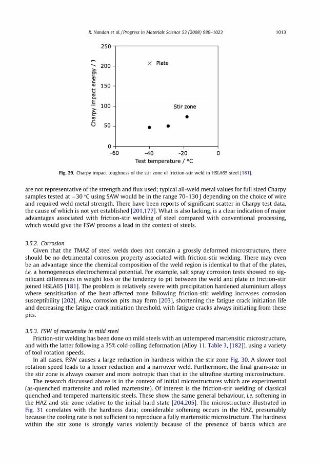
Fig. 29. Charpy impact toughness of the stir zone of friction-stir weld in HSLA65 steel [181].
R. Nandan et al. / Progress in Materials Science 53 (2008) 980–1023 1013
are not representative of the strength and flux used; typical all-weld metal values for full sized Charpysamples tested at �30 �C using SAW would be in the range 70–130 J depending on the choice of wireand required weld metal strength. There have been reports of significant scatter in Charpy test data,the cause of which is not yet established [201,177]. What is also lacking, is a clear indication of majoradvantages associated with friction-stir welding of steel compared with conventional processing,which would give the FSW process a lead in the context of steels.
3.5.2. CorrosionGiven that the TMAZ of steel welds does not contain a grossly deformed microstructure, there
should be no detrimental corrosion property associated with friction-stir welding. There may evenbe an advantage since the chemical composition of the weld region is identical to that of the plates,i.e. a homogeneous electrochemical potential. For example, salt spray corrosion tests showed no sig-nificant differences in weight loss or the tendency to pit between the weld and plate in friction-stirjoined HSLA65 [181]. The problem is relatively severe with precipitation hardened aluminium alloyswhere sensitisation of the heat-affected zone following friction-stir welding increases corrosionsusceptibility [202]. Also, corrosion pits may form [203], shortening the fatigue crack initiation lifeand decreasing the fatigue crack initiation threshold, with fatigue cracks always initiating from thesepits.
3.5.3. FSW of martensite in mild steelFriction-stir welding has been done on mild steels with an untempered martensitic microstructure,
and with the latter following a 35% cold-rolling deformation (Alloy 11, Table 3, [182]), using a varietyof tool rotation speeds.
In all cases, FSW causes a large reduction in hardness within the stir zone Fig. 30. A slower toolrotation speed leads to a lesser reduction and a narrower weld. Furthermore, the final grain-size inthe stir zone is always coarser and more isotropic than that in the ultrafine starting microstructure.
The research discussed above is in the context of initial microstructures which are experimental(as-quenched martensite and rolled martensite). Of interest is the friction-stir welding of classicalquenched and tempered martensitic steels. These show the same general behaviour, i.e. softening inthe HAZ and stir zone relative to the initial hard state [204,205]. The microstructure illustrated inFig. 31 correlates with the hardness data; considerable softening occurs in the HAZ, presumablybecause the cooling rate is not sufficient to reproduce a fully martensitic microstructure. The hardnesswithin the stir zone is strongly varies violently because of the presence of bands which are

Fig. 30. Hardness as a function of the distance from the FSW weld centreline; the horizontal line indicates the starting hardness.The upper limit of the shaded region corresponds to the slowest rotation speed and vice-versa. (a) Welded in the as-quenchedmartensitic state; (b) welded after rolling the martensite to a 35% cold reduction; (c) changes in the grain-size within the stirzone. Adapted from [182].
1014 R. Nandan et al. / Progress in Materials Science 53 (2008) 980–1023
predominantly martensitic and others which are not. Neither the impact toughness nor the ductilityobtained was adequate.
3.5.4. FSW of steels at T < Ac1
Not all steels undergo austenitisation during FSW. Alloys which are lean in carbon tend to have ahigh Ac1
1 temperature. Furthermore, because they tend to be mechanically weak, the temperaturesreached during friction-stir welding are not particularly high.
Experiments on interstitial-free steels (Alloy 3, Table 3) friction-stir welded in the ferritic condi-tion show that the scale of the final microstructure in the TMAZ depends on that of the startingmicrostructure. Originally coarse grains become much finer in the TMAZ. However, ultrafine grainsin a strong initial microstructure become coarser following FSW; this is because the heat generatedis greater when a stronger substrate is welded [122]. This can be verified from the model, as both sand p, in Eq. (2) are larger for harder work-piece material. This is illustrated in Table 4; the resultsshow that FSW will not be useful in the welding of materials with a grain-size of less than ’1 lm, ifthe objective is to preserve or refine the scale of the microstructure. Some of the fine-grained struc-tures for which FSW has been attempted show grain coarsening in the HAZ with a loss of properties[206,207].
1 Ac1 represents the lowest temperature at which austenite begins to form during heating at a specific rate – the correspondingequilibrium temperature is designated Ae1.
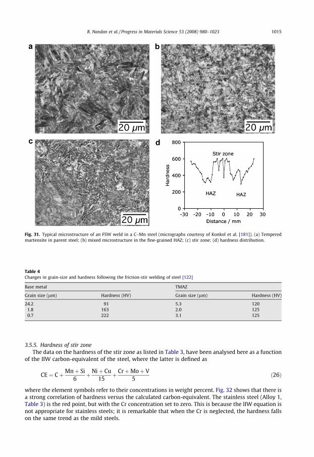
Fig. 31. Typical microstructure of an FSW weld in a C–Mn steel (micrographs courtesy of Konkol et al. [181]). (a) Temperedmartensite in parent steel; (b) mixed microstructure in the fine-grained HAZ; (c) stir zone; (d) hardness distribution.
Table 4Changes in grain-size and hardness following the friction-stir welding of steel [122]
Base metal TMAZ
Grain size (lm) Hardness (HV) Grain size (lm) Hardness (HV)
24.2 91 5.3 1201.8 163 2.0 1250.7 222 3.1 125
R. Nandan et al. / Progress in Materials Science 53 (2008) 980–1023 1015
3.5.5. Hardness of stir zoneThe data on the hardness of the stir zone as listed in Table 3, have been analysed here as a function
of the IIW carbon-equivalent of the steel, where the latter is defined as
CE ¼ CþMnþ Si6
þ Niþ Cu15
þ CrþMoþ V5
ð26Þ
where the element symbols refer to their concentrations in weight percent. Fig. 32 shows that there isa strong correlation of hardness versus the calculated carbon-equivalent. The stainless steel (Alloy 1,Table 3) is the red point, but with the Cr concentration set to zero. This is because the IIW equation isnot appropriate for stainless steels; it is remarkable that when the Cr is neglected, the hardness fallson the same trend as the mild steels.
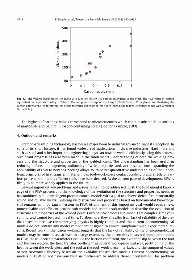
Fig. 32. The Vickers hardness of the TMAZ as a function of the IIW carbon equivalent of the steel. The >2.5 value of carbonequivalent corresponds to Alloy 1, Table 3. The red point corresponds to Alloy 1 (Table 3) with Cr neglected in calculating thecarbon equivalent. (For interpretation of the references to color in this figure legend, the reader is referred to the web version ofthis article.)
1016 R. Nandan et al. / Progress in Materials Science 53 (2008) 980–1023
The highest of hardness values correspond to microstructures which contain substantial quantitiesof martensite and bainite in carbon-containing steels (see for example, [183]).
4. Outlook and remarks
Friction-stir welding technology has been a major boon to industry advanced since its inception. Inspite of its short history, it has found widespread applications in diverse industries. Hard materialssuch as steel and other important engineering alloys can now be welded efficiently using this process.Significant progress has also been made in the fundamental understanding of both the welding pro-cess and the structure and properties of the welded joints. The understanding has been useful inreducing defects and improving uniformity of weld properties and, at the same time, expanding theapplicability of FSW to new engineering alloys. With better quantitative understanding of the under-lying principles of heat transfer, material flow, tool–work-piece contact conditions and effects of var-ious process parameters, efficient tools have been devised. At the current pace of development, FSW islikely to be more widely applied in the future.
Several important key problems and issues remain to be addressed. First, the fundamental knowl-edge of the FSW process and the knowledge of the evolution of the structure and properties needs tobe combined to build intelligent process control models with a goal to achieve, defect free, structurallysound and reliable welds. Tailoring weld structure and properties based on fundamental knowledgestill remains an important milestone in FSW. Attainment of this important goal would require new,more reliable and efficient process sub-models and reliable sub-models to describe the evolution ofstructure and properties of the welded joints. Current FSW process sub-models are complex, time con-suming, and cannot be used in real time. Furthermore, they all suffer from lack of reliability of the pre-dicted results because the underlying physics is highly complex and the current phenomenologicalmodels do not contain any model component designed to ensure compliance with experimental re-sults. Recent work in the fusion welding suggests that the lack of reliability of the phenomenologicalmodels may be contributed, at least to a large extent, by the uncertainty in several input parameters.In FSW, these uncertain parameters include the friction coefficient, the extent of slip between the tooland the work-piece, the heat transfer coefficient at several work-piece surfaces, partitioning of theheat between the work-piece and the tool at the tool–work-piece interface, and the computed valuesof non-Newtonian viscosity based on the available constitutive models. Current phenomenologicalmodels of FSW do not have any built in mechanism to address these uncertainties. This problem
R. Nandan et al. / Progress in Materials Science 53 (2008) 980–1023 1017
can be solved by combining a rigorous phenomenological process sub-model with an appropriatemultivariable optimisation scheme to determine optimised values of the uncertain variables from alimited volume of experimental data. Such an approach would result in agreement between the phe-nomenological models and the experimental results with greater degree of certainty [54–57].
However, the lack of reliability is not the only obstacle for tailoring weld attributes based on fun-damental scientific principles. An important difficulty is that the existing process models are unidirec-tional. In other words, the process sub-models require as input welding parameters, thermophysicalproperties, tool and work-piece geometry and provide, as output, the temperature and velocity fieldsand the cooling rates at various locations. In contrast, engineers should be able to specify cooling rates,the geometry of the stir zone and/or other attributes of the FSW as input and obtain as output severalalternative sets of welding parameters involving combinations of the welding speed, rotational speed,tool dimensions and other variables as output. Unless the models have a reliability component builtinto them and are bi-directional in nature, their use is likely to be restricted to researchers with onlylimited use in manufacturing and process control. Since the quantitative knowledge base in FSW isembodied in process, structure and property sub-models, these sub-models must be made more use-ful to manufacturing. Previous work in fusion welding show that such restructuring of the process,structure and property sub-models is both necessary and achievable [208,209,57]. Success of suchan undertaking will ensure availability of practically the entire quantitative knowledge base of FSWto the whole FSW community for the purpose of tailoring FSW weld attributes and fabricating defectfree, structurally sound, and reliable welds. Attainment of this milestone is well within the reach ofthe welding community within the next 10 years.
Acknowledgements
We would like to thank Dr. G.G. Roy for many helpful discussions and his interest in this work. Theresearch was supported by a grant from the Materials Division, Office of Naval Research, Dr. J. Christ-odoulu and Dr. J. DeLoach, contract monitors. One of the authors, Rituraj Nandan, is thankful to Amer-ican Welding Society for a fellowship.
References
[1] Thomas WM, Nicholas ED, Needham JC, Murch MG, Temple-Smith P, Dawes CJ. Friction stir butt welding. InternationalPatent Application No. PCT/GB92/02203; 1991.
[2] Dawes CJ, Thomas WM. Friction stir process welds aluminum alloys. Welding J 1996;75(3):41–5.[3] Thomas WM, Dolby RE. Friction stir welding developments. In: David SA, DebRoy T, Lippold JC, Smartt HB, Vitek JM,
editors. Proceedings of the sixth international trends in welding research. Materials Park, OH, USA: ASM International;2003. p. 203–11.
[4] Cho JH, Boyce DE, Dawson PR. Modeling strain hardening and texture evolution in friction stir welding of stainless steel.Mater Sci Eng A 2005;398:146–63.
[5] Liu H, Fulii H, Maeda M, Nogi K. Tensile properties and fracture locations of friction-stir welded joints of 6061-T6aluminium alloy. J Mater Sci Lett 2003;22:1061–3.
[6] Lee WB, Lee CY, Chang WS, Yeon YM, Jung SB. Microstructural investigation of friction stir welded pure titanium. MaterLett 2005;59:3315–8.
[7] Thomas WM, Nicholas ED. Friction stir welding for the transportation industries. Mater Des 1997;18:269–73.[8] Su J-Q, Nelson TW, Mishra R, Mahoney M. Microstructural investigation of friction stir welded 7050-T651 aluminium.
Acta Mater 2003;51(3):713–29.[9] Frigaard O, Grong Ø, Midling OT. A process model for friction stir welding of age hardening aluminium alloys. Metall
Mater Trans A 2001;32:1189–200.[10] Mahoney MW, Rhodes CG, Flintoff JG, Spurling RA, Bingel WH. Properties of friction-stir-welded 7075 T651 aluminum.
Metall Mater Trans A 1998;29(7):1955–64.[11] Rhodes CG, Mahoney MW, Bingel WH, Spurling RA, Bampton CC. Effect of friction stir welding on microstructure of 7075
aluminum. Scripta Mater 1997;36(1):69–75.[12] Liu G, Murr LE, Niou C-S, McClure JC, Vega FR. Microstructural aspects of the friction-stir welding of 6061-T6 aluminum.
Scripta Mater 1997;37(3):355–61.[13] Jata KV, Semiatin SL. Continuous dynamic recrystallization during friction stir welding. Scripta Mater 2000;43:743–8.[14] Masaki K, Sato YS, Maeda M, Kokawa H. Experimental simulation of recrystallized microstructure in friction stir welded Al
alloy using a plane-strain compression test. Scripta Mater 2008;58:355–60.[15] McClure JuC, Tang W, Murr LE, Guo X, Feng Z, Gould JE. A thermal model for friction stir welding. In: Vitek JM, David SA,
Johnson JA, Smartt HB, DebRoy T, editors. Trends in welding research. Ohio, USA: ASM International; 1998. p. 590–5.[16] Mishra RS, Ma ZY. Friction stir welding and processing. Mater Sci Eng R: Rep 2005;50(1–2):1–78.[17] Bever MB, Holt DL, Titchener AL. Stored energy of cold work. Prog Mater Sci 1973;17:5–192.

1018 R. Nandan et al. / Progress in Materials Science 53 (2008) 980–1023
[18] Zhu Q, Sellars CM, Bhadeshia HKDH. Quantitative metallography of deformed grains. Mater Sci Technol2007;23(7):757–66.
[19] Belous MV, Cherepin VT. Changes in the steel carbide phase under influence of cold plastic deformation. Fiz MetMetalloved 1962;14:48–54.
[20] Danoix F, Julien D, Sauvage X, Copreaux J. Direct evidence of cementite dissolution in drawn pearlitic steels observed bytomographic atom probe. Mater Sci Eng A 1998;250:8–13.
[21] Umemoto M, Liu ZG, Hao XJ, Masuyama K, Tsuchiya K. Formation of nanocrystalline ferrite through rolling and ballmilling. Mater Sci Forum 2001;360 and 362:167–74.
[22] Ivanisenko Y, MacLaren I, Valiev RZ, Fecht HJ. First observation of a shear-induced bcc to fcc transformation innanocrystalline ferrite. Adv Eng Mater 2005;7:1011–4.
[23] Lojkowski W, Ivanisenko Yu, Fecht H-J. Strain induced cementite dissolution in pearlitic steels as a classical example ofmechanical alloying. Trans Indian Inst Met 2005;58:939–1227.
[24] Gorkunov ES, Grachev SV, Smirnov SV, Somova VM, Zadvorkin SM, Kar’kina LE. Relation of physical–mechanicalproperties to the structural condition of severely deformed patented carbon steels at drawing. Russian J Nondestruct Test2005;41:65–79.
[25] Russell MJ, Shercliff H. Analytical modelling of friction stir welding. In: Russell MJ, Shercliff R, editors. INALCO’98: seventhinternational conference on joints in aluminium. Cambridge, UK: TWI; 1999. p. 197–207.
[26] Feng Z, Gould JE, Lienert TJ. A heat flow model for friction stir welding of steel. In: Bieler TR, editor. Hot deformation ofaluminium alloys. Warrendale, PA, USA: TMS–AIME; 1998. p. 149–58.
[27] Song M, Kovacevic R. Thermal modeling of friction stir welding in a moving coordinate system and its validation. Int JMach Tools Manuf 2003;43:605–15.
[28] Song M, Kovacevic R. Numerical and experimental study of the heat transfer process in friction stir welding. J Eng Manuf2003;217:73–85.
[29] Song M, Kovacevic R. Heat transfer modelling for both workpiece and tool in the friction stir welding process: a coupledmodel. J Eng Manuf 2004;218:17–33.
[30] Zhang HW, Zhang Z, Chen JT. Effect of angular velocity of pin on material flow during friction stir welding. Acta Metall Sin2005;41:853–9.
[31] Zhang HW, Zhang Z, Chen JT. Finite element simulation of the friction stir welding process. Mater Sci Eng A2005;403:340–8.
[32] Chen CM, Kovacevic R. Finite element modeling of friction stir welding – thermal and thermomechanical analysis. Int JMach Tools Manuf 2003;43:1319–26.
[33] Schmidt H, Hattel J, Wert J. An analytical model for the heat generation in friction stir welding. Modell Simul Mater SciEng 2004;12:143–57.
[34] Schmidt H, Hattel J. Heat source models in simulation of heat flow in friction stir welding. Int J Offshore Polar Eng2004;14:296–304.
[35] Schmidt H, Hattel J. Modelling heat flow around tool probe in friction stir welding. Sci Technol Weld Join2005;10:176–86.
[36] Schmidt H, Hattel J. A local model for the thermomechanical conditions in friction stir welding. Modell Simul Mater SciEng 2005;13:77–93.
[37] Khandkar MZH, Khan JA. Thermal modeling of overlap friction stir welding for Al-alloys. J Mater Process Manuf Sci2001;10:91–105.
[38] Khandkar MZH, Khan JA, Reynolds AP. Prediction of temperature distribution and thermal history during friction stirwelding: input torque based model. Sci Technol Weld Join 2003;8:165–74.
[39] Nandan R, Roy GG, DebRoy T. Numerical simulation of three-dimensional heat transfer and plastic flow during friction stirwelding. Metall Mater Trans A 2006;37:1247–59.
[40] Nandan R, Roy GG, Lienert TJ, DebRoy T. Numerical modelling of 3D plastic flow and heat transfer during friction stirwelding of stainless steel. Sci Technol Weld Join 2006;11:526–37.
[41] Nandan R, Roy GG, Lienert TJ, DebRoy T. Three-dimensional heat and material flow during friction stir welding of mildsteel. Acta Mater 2007;55:883–95.
[42] Simar A, Lecomte-Beckers J, Pardoen T, de Meester B. Effect of boundary conditions and heat source distribution ontemperature distribution in friction stir welding. Sci Technol Weld Join 2006;11:170–7.
[43] Colegrove PA, Shercliff HR. 3-Dimensional CFD modelling of flow round a threaded friction stir welding tool profile. JMater Process Technol 2005;169:320–7.
[44] Colegrove PA, Shercliff HR. Development of Trivex friction stir welding tool. Part 1 – Two-dimensional flow modelling andexperimental validation. Sci Technol Weld Join 2004;9:345–51.
[45] Bastier A, Maitournam MH, van Dang K, Roger F. Steady state thermomechanical modelling of friction stir welding. SciTechnol Weld Join 2006;11:278–88.
[46] Su P, Gerlich A, North TH, Bendzsak GJ. Energy utilisation and generation during friction stir spot welding. Sci TechnolWeld Join 2006;11(2):163–9.
[47] Colegrove PA, Shercliff HR. Development of Trivex friction stir welding tool. Part 2 – Three-dimensional flow modelling.Sci Technol Weld 2004;9:352–61.
[48] Lienert Jr TJ, Stellwag WL, Grimmett BB, Warke RW. Friction stir welding studies on mild steel. Weld J Res Suppl2003;82:1s–9s.
[49] Xu S, Deng X, Reynolds AP, Seidel TU. Finite element simulation of material flow in friction stir welding. Sci Technol WeldJoin 2001;6:191–3.
[50] Deng Z, Lovell MR, Tagavi KA. Influence of material properties and forming velocity on the interfacial slip characteristicsof cross wedge rolling. Manuf Sci Eng 2001;123:647–53.
[51] Kong HS, Ashby MF. Friction-heating maps and their applications. MRS Bull 1991;16:41–8.[52] Khan JA, Xu L, Chao YJ. Prediction of nugget development during resistance spot welding using coupled thermal–
electrical–mechanical model. Sci Technol Weld Join 1999;4:201–7.

R. Nandan et al. / Progress in Materials Science 53 (2008) 980–1023 1019
[53] Nandan R, Prabu B, De A, DebRoy T. Improving reliability of heat transfer and materials flow calculations during frictionstir welding of dissimilar aluminum alloys. Weld J 2007;86(10):313s–22s.
[54] De A, DebRoy T. Reliable calculations of heat and fluid flow during conduction mode laser welding through optimizationof uncertain parameters. Weld J 2005;84:101s–12s.
[55] De A, DebRoy T. Probing unknown welding parameters from convective heat transfer calculation and multivariableoptimization. J Phys D: Appl Phys 2006;37(1):140–50.
[56] Kumar A, Zhang W, DebRoy T. Improving reliability of modelling heat and fluid flow in complex gas metal arc fillet welds.Part I: An engineering physics model. J Phys D: Appl Phys 2005;38:119–26.
[57] Kumar A, DebRoy T. Guaranteed fillet weld geometry from heat transfer model and multivariable optimization. Int J HeatMass Transfer 2004;47(26):5793–806.
[58] Zienkiewicz OC, Cormeau IC. Visco-plasticity solution by finite-element process. Arch Mech 1972;24:872–89.[59] Sellars CM, McTegart WJ. On the mechanism of hot deformation. Acta Metall 1966;14:1136–8.[60] Sheppard T, Wright DS. Determination of flow-stress. 1: Constitutive equation for aluminum-alloys at elevated-
temperatures. Met Technol 1979;6:215–23.[61] Wright DS, Sheppard T. Determination of flow-stress. 2: Radial and axial temperature distribution during torsion testin.
Met Technol 1979;6:224–9.[62] Zener C, Hollomon JH. Effect of strain rate upon plastic flow of steel. J Appl Phys 1944;15:22–32.[63] Sheppard T, Jackson A. Constitutive equations for use in prediction of flow stress during extrusion of aluminium alloys.
Mater Sci Technol 1997;13:203–9.[64] Bruschi S, Poggio S, Quadrini F, Tata ME. Weldability of Ti–6Al–4V alloy at high temperatures and strain rates. Mater Lett
2004;58:3622–9.[65] Ulysse P. Three-dimensional modeling of the friction stir-welding process. J Mach Tools Manuf 2002;42:1549–57.[66] Dong P, Lu F, Hong JK, Cao Z. Coupled thermomechanical analysis of friction stir welding process using simplified models.
Sci Technol Weld Join 2001;6:281–7.[67] Heurtier P, Jones MJ, Desrayaud C, Driver JH, Montheillet F, Allehaux D. Mechanical and thermal modelling of friction stir
welding. J Mater Process Technol 2006;171:348–57.[68] Buffa G, Hua J, Shivpuri R, Fratini L. Design of the friction stir welding tool using the continuum based FEM model. Mater
Sci Eng A 2006;419:381–8.[69] Askari A, Silling S, London B, Mahoney M. Modelling, analysis and validation of friction stir welding and processing. J Met
2004;56:245–6.[70] Bell RL. An isotropic material remap scheme for Eulerian codes. In: Second International Conference on Cybernetics and
Information Technologies, Systems and Applications (CITSA), 2005.[71] Boyce DE, Dawson PR, Sidle B, Gnäupel-Herold T. A multiscale methodology for deformation modeling applied to friction
stir welded steel. Comput Mater Sci 2006;38:158–75.[72] Nandan R, Lienert TJ, DebRoy T. Toward reliable calculations of heat and plastic flow during friction stir welding of Ti–
6Al–4V alloy. Int J Mater Res 2008;99:434–44.[73] Bhadeshia HKDH. Mathematical models in materials science. Mater Sci Technol 2008;24:128–35.[74] Seidel TU, Reynolds AP. Two-dimensional friction stir welding process model based on fluid mechanics. Sci Technol Weld
Join 2003;8:175–83.[75] Schmidt H, Dickerson TL, Hattel J. Material flow in butt friction stir welds in AA2024-T3. Acta Mater
2006;54:1199–209.[76] Guerra M, Schmidt C, McClure JC, Murr LE, Nunes AC. Flow patterns during friction stir welding. Mater Charact
2002;49:95–101.[77] Seidel TU, Reynolds AP. Visualization of the material flow in AA2195 friction-stir welds using a marker insert technique.
Metall Mater Trans A 2001;32:2879–84.[78] Ayer R, Jin HW, Mueller RR, Ling S, Ford S. Interface structure in a Fe–Ni friction stir welded joint. Scripta Mater
2005;53:1383–7.[79] Fratini L, Buffa G, Palmeri D, Hua J, Shivpuri R. Material flow in FSW of AA7075-T6 butt joints: numerical simulations and
experimental verifications. Sci Technol Weld Join 2006;11:412–21.[80] Reynolds AP. Visualisation of material flow in autogenous friction stir welds. Sci Technol Weld Join 2000;5(2):120–4.[81] Schneider JA, Nunes AC. Characterization of plastic flow and resulting microtextures in a friction stir weld. Metall Mater
Trans B 2004;35:777–83.[82] Colligan K. Material flow behavior during friction stir welding of aluminum. Weld J Res Suppl 1999;78:229s–37s.[83] Sato YS, Kokawa H, Ikeda K, Enomoto M, Jogan S, Hashimoto T. Microtexture in the friction-stir weld of an aluminum
alloy. Metall Mater Trans A 2001;32:941–8.[84] Fonda RW, Knipling KE, Bingert JF. Microstructural evolution ahead of the tool in aluminium friction stir welds. Scripta
Mater 2008;58:343–8.[85] Baillas G, Donne CD. Characterisazion of friction stir welded joints of the aluminium alloy AA 2024-T3 by laser
extensometry. Materialprufung 2000;42:236–9.[86] Krishnan KN. On the formation of onion rings in friction stir welds. Mater Sci Eng A 2002;327:246–51.[87] Norman AF, Brough T, Pragnell PB. High resolution EBSD analysis of the grain structure in an AA2024 friction stir weld. In:
Aluminium alloys 2000: their physical and mechanical properties, parts 1–3, vols. 331–333; 2000.[88] Yang BC, Yan JH, Sutton MA, Reynolds AP. Banded microstructure in AA2024-T351 and AA2524-T351 aluminum friction
stir welds. Part I: Metallurgical studies. Mater Sci Eng A 2004;364(1–2):55–65.[89] Booth D, Sinclair I. In: Aluminium alloys 2002: their physical and mechanical properties, parts 1–3, vols. 396–402; 2002.
p. 1671–6.[90] Sutton MA, Yang B, Reynolds AP, Taylor R. Microstructural studies of friction stir welds in 2024-T3 aluminum. Mater Sci
Eng A 2002;323(1–2):160–6.[91] lee WB, Yeon YM, Jung SB. The joint properties of dissimilar formed Al alloys by friction stir welding according to the fixed
location of materials. Scripta Mater 2003;49:423–8.

1020 R. Nandan et al. / Progress in Materials Science 53 (2008) 980–1023
[92] Li Ying, Murr LE, McClure JC. Flow visualization and residual microstructures associated with the friction-stir welding of2024 aluminum to 6061 aluminum. Mater Sci Eng A 1999;271(1–2):213–23.
[93] Li Y, Murr LE, McClure JC. Flow visualization and residual microstructures associated with the friction-stir welding of2024 aluminum to 6061 aluminum. Mater Sci Eng A 1999;271(1–2):213–23.
[94] Murr LE, Li Y, Flores RD, Trillo EA, McClure JC. Intercalation vortices and related microstructural features in the friction-stir welding of dissimilar metals. Mater Res Innov 1998;2(3):150–63.
[95] Liu YL, Liu Y, Morris JG. Comparison of the evolution of microstructure and texture in DC cast and strip cast aluminumalloy AA5182 hot bands. In: Proceedings of the TMS fall meeting; 1998. p. 61–71.
[96] Attallah MM, Davis CL, Strangwood M. Influence of base metal microstructure on microstructural development inaluminium based alloy friction stir welds. Sci Technol Weld Join 2007;12:361–9.
[97] Hofmann Douglas C, Vecchio Kenneth S. Thermal history analysis of friction stir processed and submerged friction stirprocessed aluminum. Mater Sci Eng A 2007;465(1–2):165–75.
[98] Woo W, Feng Z, Wang X-L, Brown DW, Clausen B, An K, et al. In situ neutron diffraction measurements oftemperature and stresses during friction stir welding of 6061-T6 aluminium alloy. Sci. Technol. Weld. Join2007;12(4):298–303.
[99] Colegrove PA, Shercliff HR. Two-dimensional CFD modelling of flow round profiled FSW tooling. Sci Technol Weld Join2004;9:483–92.
[100] Sato Yutaka S, Kokawa Hiroyuki, Enomoto Masatoshi, Jogan Shigetoshi. Microstructural evolution of 6063 aluminumduring friction-stir welding. Metall Mater Trans A 1999;30(9):2429–37.
[101] Sato Y, Park SHC, Kokawa H. Microstructural factors governing hardness in friction-stir welds of solid-solution-hardenedAl alloys. Metall Mater Trans A 2001;32(12):3033–42.
[102] Roy GG, Nandan R, DebRoy T. Dimensionless correlation to estimate peak temperature during friction stir welding. SciTechnol Weld Join 2006;11:606–8.
[103] Sunden B. Viscous heating in forced convective heat-transfer across a circular cylinder at low Reynolds number. Int JNumer Method Eng 1992;35(4):729–36.
[104] Schmidt HB, Hattel JH. Thermal modelling of friction stir welding. Scripta Mater 2008;58:332–7.[105] Hassan KAA, Pragnell PB, Norman AF, Price DA, Williams SW. Effect of welding parameters on nugget zone microstructure
and properties in high-strength aluminium alloy friction stir welds. Sci Technol Weld Join 2003;8:257–68.[106] Su P, Gerlich A, Yamamoto M, North TH. Formation and retention of local melting films in AZ91 friction stir spot welds. J
Mater Sci 2007;42:9954–65.[107] Su J-Q, Nelson TW, Sterling CJ. A new route to bulk nanocrystalline materials. J Mater Res 2003;18(8):1757–60.[108] Fujii H, Cui L, Tsuji N, Nataka K, Nogi K, Ikeda R, et al. Transformation in stir zone of friction stir welded carbon steels with
different carbon contents. ISIJ Int 2007;47:299–306.[109] Cui Ling, Fujii Hidetoshi, Tsuji Nobuhiro, Nogi Kiyoshi. Friction stir welding of a high carbon steel. Scripta Mater
2007;56(7):637–40.[110] Sato Y, Urata M, Kokawa H. Parameters controlling microstructure and hardness during friction-stir welding of
precipitation-hardenable aluminum alloy 6063. Metall Mater Trans A 2002;33(3):625–35.[111] Peel MJ, Steuwer A, Withers PJ, Dickerson T, Shi Q, Shercliff H. Dissimilar friction stir welds in AA5083–AA6082. Part I:
Process parameter effects on thermal history and weld properties. Metall Mater Trans A 2006;37(7):2183–93.[112] Thomas WM, Johnson KI, Wiesner CS. Friction stir welding-recent developments in tool and process technologies. Adv
Eng Mater 2003;5:485–90.[113] Thomas WM. Friction stir welding – recent developments. Mater Sci Forum 2003;426–432:229–36.[114] Thomas WM, Staines DG, Johnsonand KI, Evans P. Com-stir – compound motion for friction stir welding and machining.
Adv Eng Mater 2003;5:273–4.[115] Zhao YH, Lin SB, Qu F, Wu L. Influence of pin geometry on material flow in friction stir welding process. Mater Sci Technol
2006;22:45–50.[116] Mandal A, Roy P. Modeling the compressive strength of molasses–cement sand system using design of experiments and
back propagation neural networks. J Mater Process Technol 2006;180:167–73.[117] Crawford R, Cook GE, Strauss AM, Hartman DA, Stremler MA. Experimental defect analysis and force prediction
simulation of high weld pitch friction stir welding. Sci Technol Weld Join 2006;11:657–65.[118] Liu HJ, Fujii H, Maeda M, Nogi K. Tensile fracture location characterisation of friction stir welded joints of differen
aluminium alloys. J Mater Sci Technol 2004;20:103–5.[119] Long X, Khanna SK. Modelling of electrically enhanced friction stir welding process using finite element method. Sci
Technol Weld Join 2005;10:482–7.[120] Kimand YG, Fujii H, Tsumura T, Komazaki T, Nakata K. Three defect types in friction stir welding of aluminium die casting
alloys. Mater Sci Eng A 2006;415:250–4.[121] Leal R, Loureiro A. Defect formation in friction stir welding of aluminium alloys. Adv Mater Forum II 2004;455–
456:299–302.[122] Fujii H, Ueji R, Takada Y, Kitahara H, Tsuji N, Nakata K, et al. Friction stir welding of ultrafine grained interstitial free
steels. Mater Trans JIM 2006;47:239–42.[123] Reynolds AP, Tang W, Posada M, Deloach J. Friction stir welding of DH36 steel. Sci Technol Weld Join
2003;8:455–60.[124] Colegrove PA, Shercliff HR. CFD modelling of friction stir welding of thick plate 7449 aluminium alloy. Sci Technol Weld
Join 2006;11:429–41.[125] Elangovan K, Balasubramanian V. Influences of pin profile and rotational speed of the tool on the formation of friction stir
processing zone in AA2219 aluminium alloy. Mater Sci Eng A 2007;459:7–18.[126] Kimapong K, Watanabe T. Effect of welding process parameters on mechanicl properties of FSW lap joint between
aluminium alloy and steel. Mater Trans 2005;46:2211–7.[127] Withers PJ, Bhadeshia HKDH. Residual stress. Part 1: Measurement techniques. Mater Sci Technol 2001;17:355–65.[128] Withers PJ, Bhadeshia HKDH. Residual stress. Part 2: Nature and origins. Mater Sci Technol 2001;17:366–75.
R. Nandan et al. / Progress in Materials Science 53 (2008) 980–1023 1021
[129] Francis JA, Stone HJ, Kundu S, Rogge RB, Bhadeshia HKDH, Withers PJ, et al. Transformation temperatures and weldingresidual stresses in ferritic steels. In: Proceedings of PVP2007, ASME pressure vessels and piping division conference. SanAntonio, Texas: American Society of Mechanical Engineers (ASME); 2007. p. 1–8.
[130] Ohta A, Suzuki N, Maeda Y, Hiraoka K, Nakamura T. Superior fatigue crack growth properties in newly developed weldmetal. Int J Fatigue 1999;21:S113–8.
[131] Stefanescu D, Truman CE, Smith DJ, Whitehead PS. Improvements in residual stress measurement by the incrementalcentre hole drilling technique. Exp Mech 2006;46:417–27.
[132] Ya M, Dai FL, Lu J. Study of nonuniform in-plane and in-depth residual stress of friction stir welding. J Press Vess Technol:Trans ASME 2003;125:201–8.
[133] James MN, Hattingh DG, Huges DJ, Wei LW, Patterson EA, Da Fonseca JQ. Synchrotron diffraction investigation of thedistribution and influence of residual stresses in fatigue. Fatigue Fract Eng Mater Struct 2004;27:609–22.
[134] Peel M, Steuwer A, Preuss M, Withers PJ. Microstructure, mechanical properties and residual stresses as a function ofwelding speed in aluminium AA5083 friction stir welds. Acta Mater 2003;51(16):4791–801.
[135] Chen CM, Kovacevic R. Parametric finite element analysis of stress evolution during friction stir welding. J Eng Manuf2006;220:1359–71.
[136] Khandkar MZH, Khan JA, Reynolds AP, Sutton MA. Predicting residual thermal stresses in friction stir welded metals. JMater Process Technol 2006;174:195–203.
[137] Soundararajan V, Zekovic S, Kovacevic R. Thermo-mechanical model with adaptive boundary conditions for friction stirwelding of Al 6061. Int J Mach Tools Manuf 2005;45:1577–87.
[138] Reynolds AP, Tang Wei, Gnaupel-Herold T, Prask H. Structure, properties, and residual stress of 304L stainless steelfriction stir welds. Scripta Mater 2003;48(9):1289–94.
[139] Staron P, Kocak M, Williams S. Residual stresses in friction stir welded al sheets. Appl Phys A: Mater Sci Process2002;74:S1161–2.
[140] Richards DG, Pragnell PB, Withers PJ, Williams SW, Wescott A, Oliver EC. Geometry effects when controlling residualstresses in friction stir welds by mechanical tensioning. Resid Stress VII 2006;524–525:71–6.
[141] Sutton MA. Limited weld residual stress measurements in fatigue crack propagation. Part II: FEM-based fatigue crackpropagation with complete residual stress fields. Fatigue Fract Eng Mater Struct 2006;29:537–45.
[142] John R, Jata KV, Sadananda K. Residual stress effects on near-threshold fatigue crack growth in friction stir welds inaerospace alloys. Int J Fatigue 2003;25:939–48.
[143] Jata KV, Sankaran KK, Ruschau JJ. Friction-stir welding effects on microstructure and fatigue of aluminum alloy 7050-T7451. Metall Mater Trans A 2000;31(9):2181–92.
[144] Bussu G, Irving PE. The role of residual stress and heat affected zone properties on fatigue crack propagation in frictionstir welded 2024-T351 aluminium joints. Int J Fatigue 2003;25(1):77–88.
[145] Pao PS, Gill SJ, Feng CR, Sankaran KK. Corrosion-fatigue crack growth in friction stir welded Al 7050. Scripta Mater2001;45(5):605–12.
[146] Grong Ø. Metallurgical modelling of welding. 2nd ed. London: Maney; 1997.[147] Svensson LE, Karlsson L, Larsson H, Karlsson B, Fazzini M, Karlsson J. Microstructure and mechanical properties of friction
stir welded aluminium alloys with special reference to AA 5083 and AA 6082. Sci Technol Weld Join 2000;5(5):285–96.[148] Nair SB, Pahanikumar G, Rao P, Sinah PP. Improvement of mechanical properties of gas tungsten arc and electron beam
welded AA2219 alloy. Sci Technol Weld Join 2007;12:579–85.[149] Gupta RK, Biju S, Ghosh BR, Sinha PP. Microstructural evolution and properties of friction stir welded aluminium alloy
AA2219. Aust Weld J 2007;52:35–9.[150] Paglia CS, Buchheit RG. Microstructure, microchemistry and environmental cracking susceptibility of friction stir welded
AA2219-T87. Mater Sci Eng A 2006;429:107–14.[151] Starink MJ, Seschamps A, Wang SC. The strength of friction stir welded and friction stir processed aluminium alloys.
Scripta Mater 2008;58:377–82.[152] Okuyucu H, Kurt A, Arcaklloglu E. Artificial neural network application to the friction stir welding of aluminum plates.
Mater Des 2007;28:78–84.[153] Kamp N, Sullivan A, Thomasl R, Robson JD. Modelling of heterogeneous precipitate distribution evolution during friction
stir welding process. Acta Mater 2006;54:2003–14.[154] Zhao YH, Lin SB, He ZQ, Wu L. Microhardness prediction in frictrion stir weling of 2014 aluminium alloy. Sci Technol Weld
Join 2006;11:178–82.[155] Chang CI, Lee CJ, Huang JC. Relationship between grain size and Zener–Holloman parameter during friction stir processing
in AZ31 Mg alloys. Scripta Mater 2004;51:509–14.[156] Liu HJ, Fujii H, Nogi K. Microstructure and mechanical properties of friction stir welded joints of AC4A cast aluminium
alloy. Mater Sci Technol 2004;20:399–402.[157] Ma ZY, Pilchak AL, Juhas MC, Williams JC. Microstructural refinement and property enhancement of cast light alloys via
friction stir processing. Scripta Mater 2008;58:361–6.[158] Warrington HG. Developments in magnesium alloys. Prog Met Phys 1958;2:121–48.[159] Froes FH. Advanced metals for aerospace and automotive use. Mater Sci Eng A 1994;184:119–33.[160] Forrest M, Burstow C. Magnesium – is the die cast? Mater World 2004:10–1.[161] King JF. Magnesium: commodity or exotic? Mater Sci Technol 2007;23:1–14.[162] Herold H. Recent advances in arc welding of magnesium alloys. Aust Weld J 2003;48:18–21.[163] Park Seung Hwan C, Sato Yutaka S, Kokawa Hiroyuki. Effect of micro-texture on fracture location in friction stir weld of
Mg alloy AZ61 during tensile test. Scripta Mater 2003;49(2):161–6.[164] Esparza JA, Davis WC, Trillo EA, Murr LE. Firction-stir welding of magnesium alloy AZ31B. J Mater Sci Lett
2002;21:917–20.[165] Fairman M, Afrin N, Chen DL, Cao X, Jahazi M. Microstructural evaluation of friction stir processed AZ31B-H24
magnesium alloy. Can Metall Quart 2007;46:425–32.
1022 R. Nandan et al. / Progress in Materials Science 53 (2008) 980–1023
[166] Lee WB, Kim JW, Yeon YM, Jung SB. The joint characteristics of friction stir welded AZ91D magnesium alloy. Mater Trans2003;44(5):917–23.
[167] Afrin N, Chen DL, Jahazi M. Microstructure and tensile properties of friction stir welded AZ31B magnesium alloy. MaterSci Eng A 2008;472:179–86.
[168] Mironov S, Motohashi Y, Ito T, Goloborodko A, Funami K, Kaibyshev R. Feasibility of friction stir welding for joining andmicrostructure refinement in a ZK60 magnesium alloy. Mater Trans JIM 2007;48:3140–8.
[169] Xie GM, Ma ZY, Geng L, Chen RS. Microstructural evolution and mechanical properties of friction stir welded Mg–Zn–Y–Zralloy. Mater Sci Eng A 2007;471:63–8.
[170] Cederqvist L. A weld that lasts for 100,000 years: friction stir welding of copper canisters. In: Materials Research SocietySymposium Proceedings, vol. 807. Scientific Basis for Nuclear Waste Management XXVII; 2004. p. 477–82.
[171] Lee WB, Jung SB. The joint properties of copper by friction stir welding. Mater Lett 2004;58:1041–6.[172] Sakthivel T, Mukhopadhyay J. Microstructure and mechanical properties of friction stir welded copper. J Mater Sci
2007;42:8126–9.[173] Flores OV, Kennedy C, Murr LE, Brown D, Pappu S, Nowak BM, et al. Microstructural issues in a friction-stir-welded
aluminum alloy. Scripta Mater 1998;38(5):703–8.[174] Ramirez AJ, Juhas MC. Microstructural evolution in Ti–6Al–4V friction stir welds. Mater Sci Forum 2003;426–
432:2999–3004.[175] Reynolds AP, Hood E, Tang W. Texture in friction stir welds of timetal 21s. Scripta Mater 2005;52:491–4.[176] Thomas WM, Threadgill PL, Nicholas ED. Feasibility of friction stir welding steel. Sci Technol Weld Join 1999;4:365–72.[177] Threadgill PL, Johnson R. Progress in friction stir welding of steels. Technical report 815/2004. Great Abington, Cambridge,
UK: TWI (The Welding Institute); 2004.[178] Sanders DG, Ramulu M, Klock-McCook EJ, Edwards PD, Reynolds AP, Trapp T. Characterization of superplastically formed
friction stir weld in titanium 6Al–4V: preliminary results. J Mater Eng Perform 17:187–92.[179] Maynier Ph, Jungmann B, Dollet J. Creusot–Loire system for the prediction of the mechanical properties of low alloy steel
products. In: Doane DV, Kirkaldy JS, editors. Hardenability concepts with applications to steels. Materials Park, OH,USA: TMS–AIME; 1978. p. 518–45.
[180] Fujii H, Cui L, Tsuji N, Maeda M, Nakata K, Nogi K. Friction stir welding of carbon steels. Mater Sci Eng A 2006;429:50–7.[181] Konkol PJ, Mathers JA, Johnson R, Pickens JR. Friction stir welding of HSLA-65 steel for shipbuilding. J Ship Prod
2003;19:159–64.[182] Ueji R, Fujii H, Cui L, Nishioka A, Kunishige K, Nogi K. Friction stir welding of ultrafine grained plain low-carbon steel
formed by the martensite process. Mater Sci Eng A 2006;423:324–30.[183] Ozekcin A, Jin HW, Koo JY, Bangaru NV, Ayer R, Vaughn G, et al. A microstructural study of friction stir welded joints of
carbon steels. Int J Offshore Polar Eng 2004;14:284–8.[184] Speich GR, Cuddy LJ, Gordon CR, DeArdo AJ. Formation of ferrite from control-rolled austenite. In: Marder AR, Goldstein JI,
editors. Phase transformations in ferrous alloys. Warrendale, PA, USA: TMS–AIME; 1984. p. 341–89.[185] Underwood EE. Quantitative stereology. Addison-Wesley Publication Company; 1970.[186] Czinege I, Reti T. Determination of local deformation in cold formed products by a measurement of the geometric
characteristics of the crystallites. In: Proceedings of the 18th international machine tool design and research conference,forming, vol. 1; 1977. p. 159–63.
[187] van Leeuwen Y, Vooijs S, Sietsma J, Van der Zwaag S. Effect of geometrical assumptions in modelling solid state kinetics.Metall Mater Trans A 1998;29:2925–31.
[188] Singh SB, Bhadeshia HKDH. Topology of grain deformation. Mater Sci Technol 1998;15:832–4.[189] Matsuura K, Itoh Y. Estimation of three-dimensional grain size distribution in polycrystalline material. Mater Trans JIM
1991;32:1042–7.[190] Takayama Y, Furushiro N, Tozawa T, Kato H, Hori S. A significant method for estimation of the grain size of polycrystalline
materials. Mater Trans JIM 1991;32:214–21.[191] Bate P, Hutchinson WB. Grain boundary area and deformation. Scripta Mater 2005;52:199–203.[192] Yang JR, Chang LC. Effect of stress on the Widmanstätten ferrite transformation. Mater Sci Eng A 1997;223:158–67.[193] Babu SS, Bhadeshia HKDH. Stress and the acicular ferrite transformations. Mater Sci Eng A 1992;156:1–9.[194] Shipway PH, Bhadeshia HKDH. Mechanical stabilisation of bainite. Mater Sci Eng A 1995;11:1116–28.[195] Carr MJ, Strife JR, Ansell GS. Effect of austenite prestrain above the Md temperature on the Ms temperature in Fe–Ni–Cr–C
alloys. Metall Trans A 1977;8:1471–84.[196] Chatterjee S, Wang HS, Yang JR, Bhadeshia HKDH. Mechanical stabilisation of austenite. Mater Sci Technol
2006;22:641–4.[197] Kurishita H, Kayano H, Narui M, Yamazaki M, Kano Y, Shibahara I. Effects of V-notch dimensions on charpy impact test-
results for differently sized miniature specimens of ferritic steel. Mater Trans JIM 1993;34:1042–52.[198] Bhadeshia HKDH, Strang A, Gooch DJ. Ferritic power plant steels: remanent life assessment and the approach to
equilibrium. Int Mater Rev 1998;43:45–69.[199] Shekhter A, Pereloma EV, Ringer SP. Effect of temper embrittlement and specimen size on Charpy impact testing of a Cr–
Mo–V rotor steel. Mater Sci Technol 2001;17:141–7.[200] Konkol PJ, Murczek MF. Comparison of friction stir weldments and submerged arc weldments in HSLA-65 steel. Weld J
Res Suppl 2007;86:187s–95s.[201] Posada M, DeLoach JJ, Reynolds AP, Fonda RW, Halpin JP. Evaluation of friction stir welded HSLA-65. In: Proceedings of the
fourth international friction stir welding symposium. Abington, UK: TWI; 2003 [compact disc].[202] Paglia CS, Buchhelt RG. A look in the corrosion of aluminium alloy friction stir welds. Scripta Mater 2008;58:383–7.[203] Pao PS, Gill SJ, Feng CR. On fatigue crack initiation from corrosion pits in 7075-T7351 aluminum alloy. Scripta Mater
2000;43(5):391–6.[204] Konkol PJ. Characterisation of friction stir weldments in 500 brinell hardness quenched and tempered steel. In:
Proceedings of the fourth international friction stir welding symposium. Abington, UK: TWI; 2003 [compact disc].

R. Nandan et al. / Progress in Materials Science 53 (2008) 980–1023 1023
[205] Sterling CJ, Nelson TW, Sorensen CD, Steel RJ, Packer SM. Friction stir welding of quenched and tempered C–Mn steel. In:Jata KV, Mahoney MW, Mishra RS, Semiatin SL, Lienert T, editors. Friction stir welding and processing II. Materials Park,OH, USA: TMS–AIME; 2003. p. 165–71.
[206] Fujii H, Takada Y, Tsuji N, Nogi K. Friction stir welding of ultrafine grained materials. In: Proceedings of the fifthinternational symposium on friction stir welding. Cambridge, UK: TWI; 2004. p. 1–7.
[207] Fujii H, Cui L, Tsuji N, Ueji R, Nakata K, Nogi K. Mechanical properties of friction stir welds of ultrafine grained steel andother materials. In: International offshore and polar engineering conference. Seoul: International Society of Offshore andPolar Engineers; 2005. p. 22–6.
[208] Mishra S, DebRoy T. A heat transfer and fluid flow based model to obtain a specific weld geometry using variouscombinations of welding variables. J Appl Phys 2005;98(4) [article number 044902].
[209] Rai R, DebRoy T. Tailoring weld geometry during keyhole mode laser welding using a genetic algorithm and a heattransfer model. J Phys D: Appl Phys 2006;39:1257–66.