Programming, Operating Care Manual€¦ · 4.0 DRO Mode Section Enter DRO Mode ... Program review...
111
Programming, Operating & Care Manual I Document: PIN 2031 7 Version: 0401 97 SOUTHWESTERN INDUSTRIES, INC. 2605 Homestead Place Rancho Dominguez, California 90220 Tel (310) 608-4422 1 Fax (310) 764-2668
Transcript of Programming, Operating Care Manual€¦ · 4.0 DRO Mode Section Enter DRO Mode ... Program review...

Programming, Operating & Care Manual
I Document: PIN 2031 7 Version: 0401 97
SOUTHWESTERN INDUSTRIES, INC. 2605 Homestead Place Rancho Dominguez, California 90220 Tel (310) 608-4422 1 Fax (310) 764-2668

Copyright 1997, Southwestern Industries, Inc. All rights are reserved. No part of this publication may be reproduced, stored in a retrieval system, or transmitted, in any form or by any means, mechanical, photocopying, recording or otherwise, without the prior written permission of Southwestern Industries, Inc.
While every effort has been made to include all the information required for the purposes of this guide, Southwestern Industries, Inc. assumes no responsibility for inaccuracies or omission and accepts no liability for damages resulting from the use of the information contained in this guide.
All brand names and products are trademarks or registered trademarks of their respective holders.
Southwestern Industries, Inc. 2602 Homestead Place Rancho Dominguez, CA 90224 Phn 31 01608-4422 + Fax 31 01764-2668 Service Department Phn 8001367-3165 + Fax 31 01886-8029

- rn TABLE OF CONTENTS
Section 1 .O Introduction
1.1 Turning on the ProtoTRAK MX3
Section 2.0 Description
Keyboard Soft Keys CRT Screen Pendant Back Panel Cable Box Encoders Servo MotorsIAmplifiers Ball Screw Assembly X and Y Axes Ball Screw Assembly Z Axis Emergency Stop Switch Auxiliary Function Box (option)
Section 3.0 Definitions, Terms & Concepts 9
ProtoTRAK MX3 Axis Conventions Planes and Vertical Planes Absolute & Incremental Reference Referenced and Non-Referenced Data Tool Diameter Compensation Tool Diameter Compensation When Contouring in Z Connective Events Conrad
Southwestern Industries, Inc. ProtoTRAK MX3 Programming, Operating & Care Manual

Section 4.0 DRO Mode
Section
Enter DRO Mode Clear Entry lnch to MM or MM to lnch Reset One Axis Preset Reset Absolute Reference Preset Absolute Reference Recall Absolute Position of All Axes Recall Absolute Position of One Axis Jog Power Feed Return to Absolute Zero
5.0 Proaram Mode
Enter Program Mode and Assign a Part Number Incremental Reference Position Auxiliary (AUX) Functions Programming Strategy and Procedures POSITION Events DRILL Events BOLT HOLE Events MILL Events ARC Events POCKET Event FRAME Event CONTINUE Mill HELIX Events SUBROU1-INE Events COPY Events PAUSE Events Aborting a Partially Programmed Event Editing Data While Programming an Event LOOK Finish Cuts Program Sample

1 iii
Section 6.0 Edit Mode
6.1 Enter Edit Mode 6.2 Recall and Data Correction 6.3 Adding an Event 6.4 Deleting an Event 6.5 Erasing a Program 6.6 Small Depth Adjustments
Section 7.0 Set Up Mode
7.1 Enter Set Up Mode 7.2 Inputting Tool Data 7.3 Reference Positions (REF POSN) 7.4 Tool Path Graphics 7.5 Service Codes
Section 8.0 Program Run Mode
Enter Run Mode Starting to Run Program Run Program Run Messages Stop Feed rate Override Trial Run Data Errors Fault Messages

Section 9.0 Math Help Mode
9.1 Procedure 9.2 Calculator-Math and Trig Procedures 9.3 Math Help Types
Section 1 0.0 Program Inlout Mode
10.1 Cautions About Storing and Retrieving Programs 10.2 Program Formats and Labeling 10.3 Enter Program InlOut Mode 10.4 Storing & Retrieving Programs from the Proto-TRAK MX3
Built-In Floppy Disk Drive 10.5 Backing Up Your Program 10.6 Storing & Retrieving Programs Through the RS232 Port--
Including CADICAM Generated Programs
Section I I . O service
1 1.1 Tramming the Head
Section 1 2.0 MX2e Operations
12.1 Teach 12.2 Do One 12.3 Z Jog 12.4 Programming 12.5 Graphics 1.26 Running a Two-Axis Program

SECTION
Introduction
Southwestern Industries, Inc. ProtoTRAK MX3e Programming, Operating & Care Manual

Introduction Section 1.0 1 2
1.0 INTRODUCTION Congratulations! Your ProtoTRAK MX3 is a unique, one-of-a-kind, control system which combines the simplicity of manual machining with three-axis full contouring CNC capability.
The ProtoTRAK MX3 has been designed to be effectively used in a wide variety of machining applications.
It acts like an advanced digital readout in manual machine operation. It acts like a prototyping control (MX2) to do moderately complex, low volume work. It acts like a full CNC (MX3) when programmed to do complex contouring jobs.
Section 2 of this manual provides a brief description of the ProtoTRAK MX3.
Section 3 defines some terms and concepts useful in learning to program and operate the ProtoTRAK MX3.
The ProtoTRAK MX3 is organized into seven Modes of operation which are described in the following sections.
Section 4 DRO: Digital Readout, jog, and powerfeed operations.
Section 5 PROGRAM: All input in simple machinist language.
Section 6 EDIT: Program review and edit.
Section 7 SET UP: Tool information and part graphics.
Section 8 RUN: Machining the part.
Section 9 MATH HELP: Sophisticated routines to automatically calculate points of intersection, tangency, etc.
Section 10 PROGRAM INIOUT: CADICAM interface, and program storage and retrieval

3 1 Section 1.0
1.1 Turning on the ProtoTRAK MX3
Introduction
Turn the ProtoTRAK MX3 System on by moving the on-off toggle switch on the display pendant back panel to the up position.
The display will read "Loading MX3" indicating that the system's operating software is being loaded from its floppy disk to its internal memory. This loading takes about one minute. When complete, the screen will show:
Select the Mode of operation by pressing the soft key beneath the labeled box.
SELECT MODE
If you wish to operate the system as a two-axis ProtoTRAK MX2, press the MX2 soft key. The system will reload this software.
It is recommended that the system be turned on once each day (if needed) and then turned off at night. However, the consequence of leaving the system on continuously is minor.
MX2
If the system is not used (either by a key stroke or by counting) for 20 continuous minutes, the CRT will turn itself off. Press any key or move any axis to bring the screen back to its previous display. The key you press will be ignored except to turn the screen on.
DRO
Note: When you turn the ProtoTRAK MX3 08 always wait a few seconds before turning it back on.
RUN PROG MATH
HELP
PROG
INIOUT
EDIT SET-UP

SECTION
Description
Southwestern Industries, Inc. ProtoTRAK MX3 Programming, Operating & Care Manual

Description Section 2.0 ( 5
2.0 DESCRIPTION 2.1 Keyboard (Figure I)
GO: initiates motion in Run
STOP: halts motion during Run
FEED + : feedrate override to increase feedrate
FEED r)r : feedrate override to decrease feedrate
MODE: to change from one mode of operation to another
INCIABS: switches all or one axis from incremental to absolute or absolute to incremental
INIMM: causes English to Metric or Metric to English conversion of displayed data
* : displays quick graphics in program mode
INC SET: loads incremental dimensions and general data
ABS SET: loads absolute dimensions and general data
X, Y, 2: selects axis for subsequent commands
RSTR (Restore): clears an entry, aborts a keying procedure
0-9, +I-, . : inputs numeric data with floating point format. Data is automatically + unless +I- key is pressed. All input data is automatically rounded to the system's resolution.
Beneath the CRT screen are 8 keys which are not labeled. These keys are called software programmable or soft keys. A description of the function or use of each of these keys will be shown at the bottom of the CRT screen directly above each key. If, at any time, there is no description above a key, that key will not operate.

6 ( Section 2.0 Description
The information displayed on the CRT screen is nearly always divided into 4 sections or areas.
The top line, or status line, shows the system's current status. This includes the mode, inch or mm measurement, part numbers, and servo on or off status as applicable.
Beneath the status line, and filling most of the screen, is the information area. Position data, program data, graphics, etc. are shown here.
Beneath the information area is a single "conversation" line. All instructions, prompts, messages, etc. that the control needs to communicate to you are shown on this line.
At the bottom of the CRT are boxes describing the current function or use of each soft key located under the box.
2.4 Pendant Back Panel (Figure 2)
See Figure 2 for a description of the fuses, switches, and connectors on the pendant back panel.
2.5 Computer Cabinet (Figure 3)
'The cable box provides the interface between the ProtoTRAK computer systems. See Figure 3 for a description of each connector.
2.6 Encoders (optional)
The encoders used to provide direct table and quill position feedback to the ProtoTRAK MX3 are sealed against typical shop environments and utilize the time proven gage-wheel principle. Model M250C is used on the X and Y axes. A rotary encoder is used on the Z ballscrew.
2.7 Servo MotorsIAm plifiers
The ProtoTRAK MX3 servo motor and amplifier have been combined into a single integrated package on each axis. The motors are rated 280 in-oz. maximum continuous torque which is sufficient for the heaviest cuts.

Description Section 2.0 1 7
2.8 Ball Screw Assembly X and Y Axes
The normal acme leadscrews are replaced with zero backlash, ball bearirrg leadscrews to provide accurate positioning and precise contouring.
2.9 Ball Screw Assembly Z Axis
The quill is driven through a precision ball screw to provide accurate positioning and precise contouring.
2.1 0 Emergency Stop Switch
The emergency stop (E-STOP) switch kills all power to the ProtoTRAK MX3's servo motors. The computer and pendant remain powered.
Auxiliary Function Box (option)
The optional Auxiliary Function Box provides turnkey outputs to utilize the programmable Aux functions described in Section 5.3. The box consists of:
a. An air solenoid to control spray misters or other pneumatically activated peripheral equipment. Shop air should not exceed 135 psia.
b. An automatic spindle stop connected through the E-STOP.
c. Switched and fused 120 VAC 8 Amp outlet(s) for coolant pumps, automatic oilers, etc.
d. INPUTIOUTPUT to interface with HAAS programmable indexers, dividing heads, etc.
Output from MX3 is .3 second actuation of a solid state relay between pin 3 (plus) and pin 4 (minus)
m Input to MX3 is .3 second actuation of a solid state relay between pin 1 (plus) and pin 4 (minus) Note: Pin 1 is on top, 2 on right, 3 on left, 4 on bottom
e. Toggle switch between Auto operation (up) and Manual (down). Switch to Manual to operate spindle when E-STOP is activated or MX3 is disconnected.


Figure 2
0
ONIOFF
8
0 0
8 Amp Slo Blo Fuse -. 0 Remote Stop,Go
314 Amp Slo Blo Fuse - r5232
Computer Cabinet
Cable Logic to 1 15V AC Power In -- Computer Cabinet
0
Ground Stud

Figure 3
-- Auxiliary Function Connection
Parallel Pcrt --t------a-,b
-
Cable Logic to Pendant
Program Storage Floppy Disk Drive (on front lid)
Position Encoders (TRAK Sensors)
-
Motor Connectors I I1 5V AC Power From Pendant
Switches

SECTION
Definitions, Terms & Concepts
Southwestern Industries, Inc. ProtoTRAK MX3 Programming, Operating & Care Manual

Definitions, Terms & Concepts Section 3.0 1 9
3.0 DEFINITIONS, TERMS & CONCEPTS
3.1 ProtoTRAK MX3 Axis Conventions
X Axis: positive X axis motion is defined as the table moving to the left when facing the mill. Consequently, measurement to the right is positive on the workpiece. See the figure below.
Y Axis: positive Y axis motion is defined as the table moving toward you. Measurement toward the machine (away from you) is positive on the workpiece. See the figure below.
Z Axis: positive Z axis motion is defined as moving the quill up. Measurement up is also positive on the workpiece.
The Z RAPID dimension is the position at which Z will stop rapid traversing and switch to its programmed Z feedrate. Z motion will continue until Z End depth has been reached.
I I I 1
Z RAPID
m- I I U Z END -Z

10 1 Section 3.0 Definitions, Terms & Concepts
Planes and Vertical Planes
A plane is any flat surface. If that surface lies flat on the table, it is the XY plane. That is, if you move your finger along that surface or plane, you are moving in the X and/or Y direction, but not in Z (or at least not until you pick your finger up). If you tilted that surface (think of it as a piece of paper) straight up so that it faces the front of the machine, it would be in the XZ plane. If you tilted it up so that it faced left or right, it would be in the YZ plane.
A vertical plane is any plane (or surface) tipped up on its edge on the table (see below).
3.3 Absolute & Incremental Reference
The ProtoTRAK MX3 may be programmed and operated in either (or in a combination) of absolute or incremental dimensions. An absolute reference ,from which all absolute dimensions are measured (in DRO and program operation) can be set at any point on or even off the workpiece.
To help understand the difference between absolute and incremental position, consider the following example:
I Absolute Dimensions I I
I Incremental Dimensions
I I I
Absolute Reference r\ /7 m

Definitions, Terms & Concepts Section 3.0 1 7 7
3.4 Referenced and Non-Referenced Data
Data is always loaded into the ProtoTRAK MX3 by using the INC SET or
ABS SET key. X, Y, Z positions are referenced data. In entering any X, Y, or Z position data, you must note whether it is an incremental or absolute dimension and enter it accordingly. All other information (non-referenced data), such as tool diameter, feedrate, etc. is not a position and may, therefore, be loaded with either the INC SET or ABS SET key. This manual uses the term SET when either INC SET or ABS SET may be used interchangeably.
3.5 Tool Diameter Compensation
Tool diameter compensation allows the machined edges shown directly on the print to be programmed instead of the center of the tool. The ProtoTRAK MX3 then automatically compensates for the programmed geometry so that the desired results are obtained.
If the cutter in the sketch above is moving from left to right from point X I , Y1 to X2, Y2 and on to X3, Y3, these actual points can be programmed instead of the center of the cutter.

12 ( Section 3.0 Definitions, Terms & Concepts
Or, for the sketch above, the actual desired circle with radius R can be programmed instead of the radius of the center of the cutter Rc.
Tool cutter compensation is always specified as the tool either right or left of the workpiece while looking in the direction of the tool motion. Following are examples of tool right:
Examples of tool left are:
Tool center means no compensation either right or left. That is, the centerline of the tool will be moved to the prograrr~med points.

Definitions, Terns & Concepts Section 3.0 1 13
3.6 Tool Diameter Compensation When Contouring in Z
Left and right tool diameter offsets are always those projected into the XY plane. Tool offsets in the Z direction are always up and assume the use of a ball end mill. When contouring in the Z axis, this up tool offset is always activated regardless of left, right, center.
Special attention must always be paid to tool offsets when machining with a ball end mill. The reason for this is that the tool diameter changes in the bottom part (that portion equal to the tool radius) of the tool.
The tool is always positioned at the beginning of a milling operation so that the correct point on the ball end of the tool is tangent to the beginning point, and offset perpendicular to the machined edge by the radius of the tool. Consider the example below of milling a ramp in the XZ plane from point B to point C. I I
Tool starts so end mill is tangent to BC. Rfiom center of tool is perpendicular to BC.
XZ VERl'ICAL PLANE
B
Note how the tool at the beginning point (point B) starts below (in the Z direction) point B so that it can act~~ally touch this point. If this was not true, a cusp would remain to the left of point B.
Now consider a similar example milling from A to B to C in the XZ plane.
Tool starts centered over A offset up by the tool radius R. It moves right until it is tangent to both AB and BC. Then moves to point C as in the first example.

14 1 Section 3.0 Definitions, Terms & Concepts
Note the Tool at B does not drop below the AB line and, therefore, never touches point B. As a result, a fillet is formed at point B equal to the tool radius.
This second example of continuous machining from one cut (AB) to another (BC) with full cutter compensation between, requires the two cuts to be made with events which are connective (see Section 3.7 for a more complete discussion of this requirement).
3.7 Cor~nective Events
Connective events occur between two milling events (either Mill or Arc) when the X, Y, and Z ending points of the first event are in the same location as the X, Y, and Z starting points of the next event. In addition, the tool offset and tool number of both events must be the same. And both events must lie in the XY plane or the same vertical plane (see Section 3.2).
Under special circumstances a Mill event may be connective to a Helix event, or a Helix connective to a Mill. The conditions for this are that the X, Y and Z ead points of the first event must be the same as the beginning points of the second, the Mill event must lie in the XY plane, and both events must be programmed with tool center (no rightlleft offset) and the same tool number.
3.8 Conrad
Conrad is a unique feature of the ProtoTRAK MX3 that allows you to program a tangentially connecting radius between connective events, or tangentially connecting radii for the corners of pockets and frames without the necessity of complex calculations.
For the figure below, you simply program a Mill event from X1, Y1 to X2, Y2 with tool right offset, and another Mill event from X2, Y2 to X3, Y3 also with tool right offset. During the programming of the first Mill event, the system will prompt for Conrad at which time you input the numerical value of the tangentially connecting radius (r=k). The system will calculate the tangent points T1 and T2, and direct the tool cutter to move continuously from X1, Y1 through T1, r=k, T2 to X3, Y3.

Definitions, Terms & Concepts Section 3.0 1 15
For the figure below, you program an Arc event from X I , Y1 to X2, Y2 with tool offset left, and another Arc event from X2, Y2 to X3, Y3 also with tool offset left. During the programming of the first Arc event, the system will prompt for Conrad at which time you input the numerical value of the tangentially connecting radius r=K3. The system will calculate the tangent points T I and T2 and direct the tool cutter to move continuously from X I , Y1 through T I , r=k3, T2 to X3, Y3.
\ CONRAD
Note: Conrad must always be the same as or larger than the tool radius for inside corners. Ifconrad is less than the tool radius, and an inside corner is machined, the ProtoTRAK MX3 will ignore the Conrad.
For the figure below, you program an Arc event from X I , Z1 to X2, 22, and a Mill to X3, 23. During the programming of the Arc event, the system will prompt for Conrad at which time you input the numerical value of the tangentially connecting radius r=k. The system will calculate the tangent points T I and T2 and direct the tool cutter to move continuously from X I , Z1 through T I , r=k, T2 and on to X3, 23.
X2,22 T2 X3,Z3
r = K CONRAD
W VERTICAL PLANE
+ X
X I , 2 1

SECTION
DRO Mode
Southwestern Industries, Inc. ProtoTRAK MX3 Programming, Operating & Care Manual

DRO Mode Section 4.0 1 17
4.0 DRO MODE The ProtoTRAK MX3 operates in DRO Mode as a sophisticated 3-axis digital readout with jog and power feed capability.
4.1 Enter DRO Mode
Press MODE, select DRO soft key. The CRT screen will show:
> STATUS DRO INCH
X 0.0000 INC Y 0.0000 INC Z 0.0000 INC
> INFORMATION
JOG
> CONVERSATION
> SOFT KEYS
Note the RETURN soft key is lit when in Jog or Power Feed operation
POWER
FEED
4.2 Clear Entry
Press RSTR, then re-enter all keys.
RETURN
ABS 0
RETURN

18 1 Section 4.0 DRO Mode
4.3 lnch to MM or MM to lnch
Press INIMM and note CRT screen status line.
4.4 Reset One Axis
Press X or Y or 2, INC SET. This zeros the incremental position in the selected axis.
4.5 Preset
Press X or Y or 2, numeric data, INC SET to preset selected axis.
4.6 Reset Absolute Reference
Press X or Y or 2, ABS SET to set selected axis absolute to zero at the current position. See 4.8 and 4.9 to display this data.
Note: This will also reset the incremental dimension ifthe absolute position is being displayed when it is reset.
4.7 Preset Absolute Reference
Press X or Y or 2, numeric data, ABS SET to set the selected axis absolute to a preset location for the current machine position. See 4.8 and 4.9 to display this data.
Note: This will also reset the incremental dimension if the absolute position is being displayed when it is preset.
4.8 Recall Absolute Position of All Axes
Press INCIABS. Note the dimension for each axis is labeled INC or ABS. Press INCIABS again to revert to the original reading.

DRO Mode Section 4.0 1 19
4.9 Recall Absolute Position of One Axis
Press X or Y or Z, INCIABS. Note the INC or ABS label for each axis. Repeat to get selected axis back to original reading.
4.10 Jog
The servo motors can be used to jog the table. Jogging is not allowed in Z (except with TRAK DPM).
a. Press the JOG soft key.
b. The conversation line will read "JOG + 100 ipm" indicating the table will move in the X or Y positive direction at 100 inches per minute. This message will flash to warn you that JOG is activated
c. Press +I- to reverse direction. The conversation display will read "JOG - 100 ipm." Press +I- again to go back to JOG +.
d. Press FEED * to reduce the jog speed in 10 percent increments. The conversation line will show these reductions. Press FEED + to increase the speed.
e. Press and hold X or Y to jog that axis. Note the status line will indicate "SERVO ON." Release the key to stop.
f. To jog at a prescribed rate, input the rate (for example, 25 for 25 inches per minute) and press X or Y. Press FEED + or FEED * to adjust. Press RSTR to return to 100 ipm. In metric this number represents the percent of the maximum, or 2540 mmlmin.
g. Press RETURN soft key to return to manual DRO operation.
4.11 Power Feed
The servo motors can be used as a power feed for the table, saddle or quill.
a. Press the POWER FEED soft key.
b. The conversation line will read "Power Feed 10 ipm" indicating the status and feed rate.

20 1 Section 4.0 DRO Mode
c. Press FEED rpl or FEED to adjust the feedrate from 1 ipm to 100 ipm.
d. Press X, Y or 2, the dimension you wish to move to, and INC SET.
e. Press GO to begin power feed.
f. Press STOP to halt power feed for any reason. Press GO to resume.
g. When the movement is complete, the status line will read "In Position." Repeat the process beginning at "c" above as often as you wish.
h. Press RETURN soft key to return to manual DRO operation.
4.12 Return to Absolute Zero
At any time during manual DRO operation you may automatically move the table to your absolute zero location in X and Y by pressing the RETURN ABS 0 soft key. When you do, the conversation line will read "Ready to Begin: Press Go When Ready." Make sure your tool is clear and press the GO key. When you do, the servos will turn on, move the table at rapid speed to your X and Y absolute zero position, and then turn off. You will be at zero and in manual DRO operation. Note: The quill will not be powered in this operation.

SECTION
Program Mode
Southwestern Industries, Inc. ProtoTRAK MX3 Programming, Operating & Care Manual

Program Mode
5.0 PROGRAM MODE
Section 5.0 1 22
5.1 Enter Program Mode and Assign a Part Nurr~ber and Select General Program Options
Press MODE, select PROGRAM soft key. For a new program to be written, there cannot already be a program in the active or current program memory.
If a program does not already exist when you enter the Program Mode, the conversation line will read "Program Part Number." Enter the part number (up to 8 digits) and press INC SET or ABS SET.
Note: It is not necessary to enter a part number. ynone is entered and the INC SET or ABS SET button is pushed, the system will assume a part number 0.
If there is already a program when the Program Mode is entered, the last event of this program will appear on the screen. Additional events may be added after the last event of this program. It will be necessary to erase this program first before creating a new program. The procedure to erase a program in order to create a new program is found in Section 6.5. The procedure to save a program for future use before erasing is found in Section 10.
When a new part number (for a new program) has been entered, the display will show:
> STATUS PROGRAM 12345 INCH
GENERAL PROGRAM OPTIONS: Scale: 1.000 Dwell Request: YES or NO Auxiliary Function Request: YES or NO
SCALE 1.0000 > CONVERSATION
> SOFT KEYS DATA
FWD
DATA
BACK
CONT

23 1 Section 5.0 Program Mode
Where:
Scale: Asks for a scale factor between . I and 10. An input of 5 means the part will be 5 times as big as the programmed dimensions. A value of 1.0000 is assumed if nothing is input.
Dwell Request: Asks if you wish to input a dwell at the bottom of a drill or bore cycle for any event. Select the appropriate YES or NO soft key. If you select YES you will be prompted to input a dwell time in seconds from . I to 99.9 when appropriate. Press DATA FWD to bring this option to the conversation line.
Auxiliary Function Request: Asks if you wish to activate any of the optional auxiliary functions (see Section 5.3) at any time during the program. Select the appropriate YES or NO soft key. If you select YES you will be prompted to input the type and sequencing of the aux functions when appropriate. Press DATA FWD to bring this option to the conversation line.
When the General Program Options have been selected press CONT (continue), the display will show the Select Event screen:
pressing PAGE changes the soft keys to:
PROGRAM PIN 12345 INCH
EVENT I
SELECT EVENT
> STATUS
POSN
> INFORMATION
> CONVERSATION
> SOFT KEYS DRILL BOLT
HOLE
CONTIN
MlLL
MlLL
HELIX
ARC
SUB COPY
PAGE POCKET FRAME
PAUSE PAGE

Program Mode Section 5.0 1 24
5.2 Incremental Reference Position
When X, Y, Z RAPlD and Z data for the beginning position of any event are input as incremental data, this increment must be measured from some known point in the previous event. Following are the positions for each event type from which the incremental moves are made in the subsequent event:
Position: X, Y and Z programmed
Drill: X, Y, Z RAPID, and Z END programmed
Bolt Hole: X CENTER, Y CENTER, Z RAPlD and Z END programmed
Mill: X END, Y END, Z RAPlD and Z END programmed
Arc: X END, Y END, Z RAPlD and Z END programmed
Circle (POCKET or FRAME): X CENTER, Y CENTER, Z RAPlD and Z END programmed
Rectangle or Poly (POCKET or FRAME): X I and Y1 corner, Z RAPlD and Z END programmed
Helix: The X END, Y END, Z RAPID, and Z END programmed
Sub: The reference position as defined for the specific events above for the event prior to the first event which was repeated.
Continue Mill: The appropriate reference position as defined for the specific +events above for the last event which is programmed
For example, if an ARC event followed a MlLL event, a 2.0 inch incremental X BEG would mean that in the X direction the beginning of the ARC event is 2.0 inches from the end of the MlLL event.

25 1 Section 5.0 Program Mode
5.3 Auxiliary (AUX) Functions
The ProtoTRAK MX3 has the capability to control four different auxiliary functions. In addition, you can select whether to activate or deactivate these functions at the beginning or end of each event.
If AUX functions are selected during the General Programming Options, the system will prompt for AUX BEG and AUX END in each event. You must input a 1 and/or 2 and/or 3 and/or 4 and SET to perform the following:
AUX BEG 1 : Activates a switched AC relay in the Auxiliary Function Box at the beginning of the event. This is typically used for the coolant pump.
AUX END 1 : Deactivates the above relay at the end of the event
AUX BEG 2: Turns on an air solenoid in the Auxiliary Function Box at the beginning of the event
AUX END 2: Turns the above air solenoid off at the end of the event
AUX BEG 3: Activates a 0.3 second electronic pulse contact in the Auxiliary Function Box at the beginning of the event
AUX END 3: Activates the above contact at the end of the event
AUX END 4: Activates a signal (normally reserved for the spindle) in the Auxiliary Function Box at the end of the event
Note: The AUX 3 function is basically designed to operate with a Haas (or other type) indexer. When used this way, program a PAUSE event with an AUXEND 3. The ProtoTRAK MX3 will automatically be placed in a STOP condition (because of PAUSE). The AUXEND 3 signal will go to the indexer. When complete, most products are designed to send out a signal (see Section 2.11) which the ProtoTRAK MX3 will interpret as a GO to continue to the next event without your input.
Note: An AUXEND 4 signal is automatically programmed for the end of any event prior to a tool change.
Note: It is the customer's responsibility to properly electronically connect all auxiliary function devices. See Section 2.11 for connection data.
Program Mode Section 5.0 1 26
5.4 Programming Strategy and Procedures
The ProtoTRAK MX3 makes programming easy by allowing you to program the actual part geometry as defined by the print. The Select Event screen (5.1) is basically a list of all the types of geometry that can be machined with this control on a mill.
The basic strategy is to select the soft key event type (geometry) and then follow all instructions in the conversation line. When an event is selected, all the prompts which need to be input will be shown on the right side of the information area. The first prompt will be highlighted and also shown in the conversation line. Input the dimension or data requested and press INC SET or ABS SET. For X or Y dimension data it is very important to properly select INC SET or ABS SET. For all other data either SET will do.
As data is being entered it will show in the conversation line. When SET, the data will be transferred to the information area, and the next prompt will be shown in the conversation line.
You may press the DATA FWD or DATA BACK soft keys to go back to edit any data within an event. Simply shift forward or back to get the prompt in the conversation line and re-input the data. At any time before the event is complete you may cancel the event by pressing the ABORT EVENT soft key.
When all data for an event has been entered, the entire event will be shifted to the left side of the screen and the conversation line will ask you to select the next event.
5.4.1 Assumed Tool Offset, Feedrate, and Tool #
The ProtoTRAK MX3 will automatically program the following by simply pressing SET:
Tool Offset: for a Mill or Arc Event, same as the last event if that event was a Mill or Arc event
Feedrate: same as last event if that event was a Mill, Arc, Pocket, Frame, or Helix
Tool #: same as last event
You may change these assumed inputs by simply inputting the desired data when the event is programmed.
5.4.2 Z Rapid Positioning
Between any two events the quill will always move to the higher of the Z rapid of the event just completed or the Z Rapid of the next event, unless the two events are connective (see Section 3.7). Remember, two milling events are not connective unless they lie in the same plane.

27 1 Section 5.0 Program Mode
5.5 POSITION Events
This event type positions the table and quill at a specified position. The positioning is always at rapid speed (modified by feedrate override) and in the most direct path possible from the previous location.
To program a Position event press the POSN soft key on the Select Event screen (see Section 5.1). The following screen will appear:
> STATUS PROGRAM PIN 12345 INCH
EVENT --- POSITIONIDRILL X Y Z RAPID
TOOL #
X
> INFORMA TION
DATA
FWD
> CONVERSATION
> SOFT KEYS
Where:
X is the X dimension to the position
Y is the Y dimension to the position
Z Rapid is the Z dimension to the position
Tool # is the tool number you assign
DATA
BACK
5.6 DRILL Events
ABORT
EVENT
This event positions the table to the specified X and Y position, moves the quill at rapid to the Z RAPID location, feeds the quill to the Z END location, and rapids back to Z RAPID for drill, and feeds back for bore.
Press the DRILL soft key. The screen will show:

Program Mode Section 5.0 1 28
> STATUS PROGRAM PIN 12345 INCH EVENT DRILL DRILL=I BORE=2 X Y Z RAPID Z END # PECKS Z FEEDRATE TOOL #
X > CONVERSATION
> SOFT KEYS
Where:
Drill=l, Bore=2: selects whether the hole is to be drilled or bored
ABORT
EVENT
DATA
FWD
X: is the X dimension to the hole
Y: is the Y dimension to the hole
Z Rapid: is the Z dimension to transition from rapid to feed
DATA
BACK
Z End: is the bottom of the hole
# Pecks: is the number of tool withdrawal cycles (each cycle drills progressively less and retracts to the Z Rapid position). See Section 7.5.6 for fixed depth cycles.
Z Feedrate: is the drilling feedrate
Tool #: is the tool number you assign

29 1 Section 5.0 Program Mode
5.7 BOLT HOLE Events
This event allows you to program a bolt hole pattern without needing to compute and program the position of each hole.
Press the BOLT HOLE soft key. The screen will show:
> STATUS PROGRAM PIN 12345 INCH EVENT - - - BOLT HOLE DRILL=I BORE=2 # HOLES
X CENTER Y CENTER Z RAPID Z END
RADIUS ANGLE # PECKS Z FEEDRATE TOOL #
# HOLES
> INFORMATION
> CONVERSATION
ABORT
WENT
DATA
FWD
> SOFT KEYS DATA
BACK
Where:
Drill=l, Bore=2: selects whether the hole is to be drilled or bored
# Holes: is the number of holes in the bolt hole pattern
X Center: is the X dimension to the center of the hole pattern
Y Center: is the Y dimension to the center of the hole pattern
Z Rapid: is the Z dimension to transition from rapid to feed
Z End: is the bottom of the hole
Radius: is the radius of the hole pattern from the center to the center of the holes
Angle: is the angle from the positive X axis (that is 3 o'clock) to any hole; positive angle is measured counterclockwise from 0.000 to 359.999 degrees
# Pecks: is the number of tool withdrawal cycles (each cycle drills progressively less and retracts to the Z Rapid position). See Section 7.5.6 for fixed depth cycles.
Z Feedrate: is the drilling feedrate
Tool #: is the tool number you assign

Program Mode Section 5.0 1 30
5.8 MlLL Events
This event allows you to mill in a straight line from any one XYZ point to another, including at a diagonal in space. It may be programmed with a CONRAD if it is connective with the next event (this next event must lie in the same plane as the Mill event).
Press the MlLL soft key. The screen will show:
> STATUS PROGRAM PIN 12345 INCH EVENT-- - MlLL X BEGIN Y BEGIN Z RAPID Z BEGIN X END Y END Z END CONRAD TOOL OFFSET Z FEEDRATE XYZ FEEDRATE TOOL #
X BEGIN > CONVERSATION
> SOFT KEYS
Where:
X Begin: is the X dimension to the beginning of the mill cut
Y Begin: is the Y dimension to the beginning of the mill cut
Z Rapid: is the Z dimension to transition from rapid to feed
Z Begin: is the Z dimension to the beginning of the mill cut
X End: is the X dimension to the end of the mill cut; incremental is X Begin
Y End: is the Y dimension to the end of the mill cut; incremental is Y Begin
Z End: is the Z dimension to the end of the mill cut; incremental is Z Begin
ABORT
EVENT
DATA
FWD
DATA
BACK

31 1 Section 5.0 Program Mode
Conrad: is the dimension of a tangential radius to the next event (which must lie in the same plane)
Tool Offset: is the selection of the tool offset to right (input I), offset to left (input 2), or tool center--no offset (input 0) relative to the programmed edge and direction of tool cutter movement
Z Feedrate: is the Z feedrate from Z Rapid to Z begin
XYZ Feedrate: is the milling feedrate from Begin to End in inlmin from .I to 99.9, or mmlmin from 5 to 2500
Tool #: is the tool number you assign
This event allows you to mill with circular contouring any arc (fraction of a circle) that lies in the XY plane or a vertical plane (see Section 3.2). Vertical plane arcs are also limited to those which are entirely concave or convex (in other words, if you think of the arc lying on the surface of the earth, then it can't cross the equator).
In ARC events when X Center, Y Center, and Z Center are programmed incrementally, they are referenced from X End, Y End, and Z End respectively. An ARC event may be programmed with a CONRAD if it is connective with the next event (this next event must lie in the same plane as the Arc event).
Note: When an arc is a 180° arc, there are several paths that all have the same beginning, ending, and center locations. Consider, ifyou were on the equator and you wanted to get to the other side of the earth you could go clockwise or counterclockwise around the equator, or you could go up over the north pole, or down under the south pole. The ProtoTRAK MX3 will automatically assume that all 180° arcs that have the same beginning, ending and center dimensions for Z, lie in the XYplane. Ifyou want a 180° arc in a vertical plane, you must program two 90° arcs or some equivalent.
Press the ARC soft key. The screen will show:

Program Mode Section 5.0 1 32
> STATUS
> INFORMA TlON
> CONVERSA TlON
> SOFT KEYS
I
PROGRAM PIN 12345 INCH EVENT- - - ARC X BEGIN Y BEGIN Z RAPID Z BEGIN X END Y END Z END X CENTER Y CENTER Z CENTER CONRAD DIRECTION TOOL OFFSET Z FEEDRATE XIZ FEEDRATE TOOL #
X BEGIN
Where:
X Begin: is the X dimension to the beginning of the arc cut
ABORT
EVENT
DATA
FWD
Y Begin: is the Y dimension to the beginning of the arc cut
I I I I I I I I
DATA
BACK
Z Rapid: is the Z dimension to transition from rapid to feed
Z Begin: is the Z dimension to the beginning of the arc cut
X End: is the X dimension to the end of the arc cut; incremental is from X Begin
Y End: is the Y dimension to the end of the arc cut; incremental is from Y Begin
Z End: is the Z dimension to the end of the arc cut; incremental is from Z Begin

33 1 Section 5.0 Program Mode
X Center: is the X dimension to the center of the arc; incremental is from X End
Y Center: is the Y dimension to the center of the arc; incremental is from Y End
Z Center: is the Z dimension to the center of the arc; incremental is from Z End
Conrad: is the dimension of a tangential radius to the next event (which must lie in the same plane)
Direction: is the clockwise (input I ) , or counterclockwise (input 2) direction of the arc as viewed looking down for an arc in the XY plane, looking from the front for a vertical plane, or looking from the right for a vertical YZ plane
Tool Offset: is the selection of the tool offset to right (input I ) , offset to left (input 2), or tool center--no offset (input 0) relative to the programmed edge and direction of tool cutter movement
Z Feedrate: is the Z feedrate from Z Rapid to Z Begin
XYZ Feedrate: is the milling feedrate from Begin to End in inlmin from . I to 99.9, or mmlmin from 5 to 2500
Tool #: is the tool number you assign
5.10 POCKET Event
This event allows you to machine circular, rectangular, 3 or 4-sided polygon, and irregular shaped pockets in the XY plane. Pockets include machining the circumference, as well as all the material inside the circumference of the programmed shape. If a finished cut is programmed, it will be made at the completion of the final pass.
Press the POCKET soft key. The screen will show:
> STATUS PROGRAM PIN 12345 INCH EVENT
SELECT POCKET TYPE
> INFORMA TlON
CIRCLE
> CONVERSA TlON
> SOFT KEYS RECT
ANGLE
RETURN 3 SIDE
POLY
4 SIDE
POLY
IRREG
ULAR

Program Mode Section 5.0 ( 34
Circular Pocket
Press the CIRCLE soft key if you wish to mill a circular pocket. The screen will show:
> STATUS PROGRAM PIN 12345 INCH EVENT- - -CIRCULAR POCKET
X CENTER
Y CENTER
Z RAPID
Z END
RADIUS DIRECTION
# PASSES FIN CUT
Z FEEDRATE
X / Z FEEDRATE
FINISH FEEDRATE
TOOL #
X CENTER
> INFORMATION
DATA
FWD
> CONVERSATION
> SOFT KEYS DATA
BACK
Where:
ABORT
EVENT
X Center: is the X dimension to the center of the circle
Y Center: is the Y dimension to the center of the circle
Z Rapid: is the Z dimension to transition from rapid to feed
Z End: is the Z dimension at the bottom of the pocket; incremental is from the previous event (see Section 5.2)
Radius: is the finish radius of the circle
Direction: is the clockwise (input I ) , or counterclockwise (input 2) direction for milling
# Passes: number of cycles to machine to the final depth spaced equally ,from Z Rapid to Z End (hint: keep Z Rapid small)
Fin Cut: is the width of the finish cut. If 0 is input, there will be no finish cut
Z Feedrate: is the Z feedrate from Z rapid to Z begin
Feedrate: is the milling feedrate in inlmin from . I to 99.9, or mmlmin from 5 to 2500
Finish Feedrate: is the milling feedrate for the finish cut
Tool #: is the tool number you assign

35 1 Section 5.0 Program Mode
5.10.2 Rectangular Pocket
Press RECTANGLE soft key if you wish to mill a rectangular pocket (all corners are 90° right angles and the sides are parallel to the X and Y axes). The screen will show:
> STATUS PROGRAM PIN 12345 INCH M N T - - -RECT POCKET X1 Y1
x3 Y3 Z RAPID Z END CONRAD DIRECTION # PASSES FIN CUT Z FEEDRATE XYZ FEEDRATE FINISH FEEDRATE TOOL #
X I
> INFORMATION
> CONVERSATION
> SOFT KEYS ABORT
EVENT
DATA
FWD
Where:
DATA
BACK
X I : is the X dimension to any corner
Y1: is the Y dimension to the same corner as X I
X3: is the X dimension to the corner opposite X I ; incremental is from X I
Y3: is the Y dimension to the same corner as X3; incremental is from Y1
Z Rapid: is the Z dimension to transition from rapid to feed
Z End: is the Z dimension at the bottom of the pocket; incremental is from the previous event (see Section 5.2)
Conrad: is the value of the tangential radius in each corner
Direction: is the clockwise (input I ) , or counterclockwise (input 2) direction for milling
# Passes: is the number of cycles to machine to the final depth spaced equally from Z Rapid to Z End (hint: keep Z Rapid small)
Fin Cut: is the width of the finish cut. If 0 is input there will be no finish cut

Program Mode Section 5.0 1 36
Z Feedrate: is the Z feedrate from Z rapid to Z end
XYZ Feedrate: is the milling feedrate in inlmin from .1 to 99.9, or mmlmin from 5 to 2500
Finish Feedrate: is the milling feedrate for the finish cut
Tool #: is the tool number you assign
5.10.3 3-Sided or 4-Sided Polygon Pocket
Press the 3 SlDE POLY or 4 SlDE POLY soft key if you wish to mill a 3 or 4 sided polygon pocket.
Note: The 4-sided polygon pocket may not have an interior angle between adjacent sides that is greater than 180 degrees.
The screen will show:
Where:
XI : is the dimension to any corner
PROGRAM PIN 12345 INCH EVENT- - -POLYGON POCKET XI Y1 X2 Y2
x3 Y3 X4 (4 SlDE ONLY) Y4 (4 SlDE ONLY)
Z RAPID Z END
CONRAD # PASSES FIN CUT Z FEEDRATE X W FEEDRATE
FINISH FEEDRATE TOOL #
X I -
> STATUS
DATA
FWD
> CONVERSATION
> SOFT KEYS
Yl : is the dimension to the same corner as X I
DATA
BACK
ABORT
EVENT

3 7 1 Section 5.0 Program Mode
X2, 3, 4: is the dimension to each other corner; incremental is from the previous corner
Y2, 3, 4: is the dimension to the same corner as X2, 3, 4; incremental is from the previous corner
Z Rapid: is the Z dimension to transition from rapid to feed
Z End: is the Z dimension at the bottom of the pocket; incremental is from the previous event (see Section 5.2)
Conrad: is the value of the tangential radius in each corner
# Passes: is the number of cycles to machine to the final depth spaced equally from Z Rapid to Z End (hint: keep Z Rapid small)
Fin Cut: is the width of the finish cut. If 0 is input, there will be no finish cut
Z Feedrate: is the Z feedrate from Z rapid to Z end
XYZ Feedrate: is the milling feedrate in inlmin from .I to 99.9, or mmlmin from 5 to 2500
Finish Feedrate: is the milling feedrate for the finish cut
Tool #: is the tool number you assign
5.10.4 Irregular Pocket
Press the IRREGULAR soft key if you wish to mill an irregular shaped pocket made up of straight lines (Mills) and arcs. The first screen in an irregular pocket defines some of its general parameters. The screen will show:
> STATUS PROGRAM PIN 12345 INCH EVENT- - -1RREG TOOL OFFSET # PASSES Z FEEDRATE XYZ FEEDRATE FIN CUT FIN FEEDRATE TOOL #
TOOL OFFSET, O=CENTER, l=RIGHT, 2=LEFT
> INFORMATION
DATA
FWD
> CONVERSATION > SOFT KEYS DATA
BACK
ABORT
M N T

Program Mode Section 5.0 1 38
Where:
Tool Offset: Is the selection of the tool offset to the right (input I ) , or offset to the left (input 2) in the programmed direction around the pocket perimeter. Do not select 0 for tool center. In other words, input 1 if programming clockwise around the perimeter, or input 2 if counterclockwise
# Passes: is the number of cycles to machine to the final depth spaced equally from Z rapid to Z end (hint: keep Z Rapid small)
Z Feedrate: is the Z feedrate from Z rapid to Z end
XYZ Feedrate: is the milling feedrate in inlmin from . I to 99.9, or mmlmin from 5 to 2500
Fin Cut: is the width of the finish cut. If 0 is input there will be no finish cut
Fin Feedrate: is the finish cut milling feedrate in inlmin from . I to 99.9, or mmlmin from 5 to 2500
Tool #: is the tool number you assign
When the above screen is complete, you need to define the shape of the pocket using MILL and ARC events with (or without) Conrads. The ProtoTRAK MX3 will prompt for each event (or side of the pocket) in the same way as mill and arc events. When the last side is programmed, press the END CONTIN soft key.
There are a few rules which must be followed to program a legitimate pocket.
1. The pocket may have no more than 20 sides.
2. The last side (or event) must end where the first side (or event) began.
3. No "islands" may exist in the pocket.
4. The pocket is cleared by zig-zag machining along the X axis starting at the most negative Y position. Consequently, there must not be "hidden" sections when machining along X. For example, the cross-hatched section below is "hidden."
Note: If your part has hidden sections, program it as two pockets.

39 1 Section 5.0 Program Mode
In Program Run, the pocket path will be zig-zag cuts along X, followed by a rough cut along the inside of the perimeter. This will be repeated for each pass and then followed by a finish pass (if FIN CUT was not zero) along the inside of the perimeter at the Finish Feedrate and final depth.
5.11 FRAME Event
This event allows you to mill around the outside or inside of a circular or rectangular circumference in the XY plane. If you wish to frame an irregular shape, simply use the Continue Mill feature (see Section 5.12).
Press the FRAME soft key. The screen will show:
] > STATUS PROGRAM PIN 12345 INCH
SELECT
> INFORMATION
> CONVERSATION
> SOFT KEYS CIRCLE RECT
ANGLE
RETURN

Program Mode Section 5.0 1 40
Circle Frame
Press the CIRCLE soft key if you wish to mill a circular frame. The screen will show:
> STATUS
> INFORMATION
PROGRAM PIN 12345 INCH EVENT- - - CIRCLE FRAME
X CENTER
Y CENTER
Z RAPID
Z END
RADIUS
DIRECTION
# PASSES
TOOL OFFSET
FIN CUT
Z FEEDRATE
XIZ FEEDRATE
FINISH FEEDRATE
TOOL #
X CENTER > CONVERSATION
> SOFT KEYS DATA
FWD
Where:
X Center: is the X dimension to the center of the circle
DATA
BACK
Y Center: is the Y dimension to the center of the circle
ABORT
EVENT
Z Rapid: is the Z dimension to transition from rapid to feed
Z End: is the Z dimension to the bottom of the frame; incremental is from the previous event (see Section 5.2)
Radius: is the finish radius of the circle
Direction: is the clockwise (input I ) , or counterclockwise (input 2) direction for milling
# Passes: is the number of cycles to machine to the final depth spaced equally from Z Rapid to Z End (hint: keep Z Rapid small)
Tool Offset: is the selection of the tool offset to the right (input I ) , offset to the left (input 2), or tool center--no offset (input 0) relative to the programmed edge and direction of the cutter movement
Fin Cut: is the width of the finish cut. If 0 is input, there will be no finish cut
41 1 Section 5.0 Program Mode
Z Feedrate: is the Z feedrate from Z rapid to Z end
XYZ Feedrate: is the milling feedrate in inlmin from .1 to 99.9, or mmlmin from 5 to 2500
Finish Feedrate: is the milling feedrate for the finish cut
Tool #: is the tool number you assign
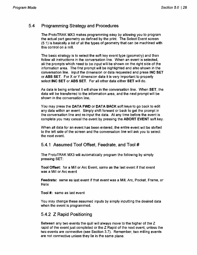
5.1 1.2 Rectangular Frame
Press the RECTANGLE soft key if you wish to mill a rectangular frame (all corners are 900 right angles). The screen will show:
> STATUS PROGRAM PIN 12345 INCH EVENT- - -RECT FRAME X 1 Y1 X3 Y3 Z RAPID Z END CONRAD DIRECTION # PASSES TOOL OFFSET FIN CUT Z FEEDRATE XYZ FEEDRATE FINISH FEEDRATE TOOL #
X I
> INFORMA TlON
> CONVERSA TlON
> SOFT KEYS ABORT
EVENT
DATA
FWD
Where:
XI: is the X dimension to any corner
Y1: is the Y dimension to the same corner as X1
X3: is the X dimension to the corner opposite X I ; incremental is from X1
Y3: is the Y dimension to the same corner as X3; incremental is from Y1
DATA
BACK
Z Rapid: is the Z dimension to transition from rapid to feed

Program Mode Section 5.0 1 42
Z End: is the Z dimension at the bottom of the frame; incremental is from the previous event (see Section 5.2)
Conrad: is the value of the tangential radius in each corner
Direction: is the clockwise (input I ) , or counterclockwise (input 2) direction for milling
Tool Offset: is the selection of the tool offset to the right (input I ) , offset to the left (input 2), or tool center--no offset (input 0) relative to the programmed edge and direction of the cutter movement
# Passes: is the number of cycles to machine to the final depth spaced equally from Z Rapid to Z End (hint: keep Z Rapid small).
Fin Cut: is the width of the finish cut. If 0 is input, there will be no finish cut
Z Feedrate: is the Z feedrate from Z rapid to Z end
XYZ Feedrate: is the milling feedrate in inlmin from .1 to 99.9, or mmlmin from 5 to 2500
Finish Feedrate: is the milling feedrate for the finish cut
Tool #: is the tool number you assign
5.12 CONTINUE Mill
The purpose of Continue Mill is to substantially reduce the required data input when programming a series of connective mill andlor arc events. Remember that events are connective if the X, Y, Z end points of one event are the same as the beginning of the next, the tool offsets are the same, the tool number is the same, and the events lie in the same plane. In other words, if the machining is continued from one event to the next.
Continue Mill is not a single event. It simply signals the control that a series of connective events will be programmed next, so a very abbreviated set of prompts will be required.
Press the CONTIN MILL soft key. The screen will show:

43 1 Section 5.0 Program Mode
> STATUS PROGRAM PIN 12345 INCH
SELECT
> INFORMATION
> CONVERSATION
>SOFT KEYS ABORT EVENT
MILL
Select the appropriate soft key to define the first segment of the connective series. The screen will revert to the Mill Event screen (see Section 5.8), or ARC Event screen (see Section 5.9). Input the data as you would normally.
ARC
When the last piece of data has been entered, the screen will show:
> STATUS PROGRAM PIN 12345 INCH
SELECT
> INFORMA TlON
MILL
> CONVERSA TlON
>SOFT KEYS ARC CW
If you select MILL, then a Mill Event will be established requiring only these prompts:
X End: the X dimension to the end of the mill cut; incremental is the beginning location
ARC CCW
Y End: the Y dimension to the end of the mill cut; incremental is the beginning location
END CONTIN

Program Mode Section 5.0 1 44
Z End: the Z dimension to the end of the mill cut; incremental is the beginning location
Conrad: the connective radius to the next event
rn If you select ARC CW or ARC CCW an Arc Event (in the clockwise or counterclockwise direction) will be established requirirrg only these prompts:
X End: the X dimension to the end of the arc cut; incremental is the beginning location
Y End: the Y dimension to the end of the arc cut; incremental is the beginning location
Z End: the Z dimension to the end of the arc cut; incremental is the beginning location
X Center: the X dimension to the center of the arc; incremental is the end location
Y Center: the Y dimension to the center of the arc; incremental is the end location
Z Center: the Z dimension to the center of the arc; incremental is the end location
CONRAD: the connective radius to the next event
rn If you select END CONTIN, you signal that the series of connective events is over. The screen will ask you to select a new event as shown in Section 5.1.
5.13 Helix Events
The Helix Event allow you to machine in a circular path in the XY plane while you simultaneously move the Z axis linearly.
Under special circumstances a Mill event may be connective to a Helix event, or a Helix connective to a Mill. The conditions for this are that the XI Y and Z end points of the first event must be the same as the beginning points of the second, the Mill event must lie in the XY plane, and both events must be programmed with tool center (no rightlleft offset) and the same tool number.
Press the HELIX soft key. The screen will show:

45 1 Section 5.0 Program Mode
> STATUS PROGRAM PIN 12345 INCH
M N T - -- HELIX
X CENTER
Y CENTER
Z RAPID
Z BEGIN
Z END
RADIUS
ANGLE
# REV
DIRECTION
TOOL OFFSET Z FEEDRATE
XYZ FEEDRATE
TOOL #
FIRST EVENT #
> INFORMA TlON
> CONVERSA TlON
ABORT
M N T
DATA FWD >SOFT KEYS
DATA
BACK
Where:
X Center: is the X dimension to the center of rotation of the helix
Y Center: is the Y dimension to the center of rotation of the helix
Z Rapid: is the Z dimension to transition from rapid to feed
Z Begin: is the Z dimension to the beginning of the helix
Z End: is the Z dimension at the end of the helix
Radius: is the radius from the center of rotation to the helix
Angle: is the angle from the positive X axis (that is, 3 o'clock) to the starting position of the helix
# Rev: is the number of revolutions in the helix, for example, 0.75 would be 270 degrees, or 3.25 would be three times around plus 90 degrees
Direction: is the clockwise (input 1) or counterclockwise (input 2) direction of the helix
Tool Offset: is the selection of the tool offset to right (input I ) , offset to left (input 2), or tool center--no offset (input 0) relative to the programmed edge and direction of the cutter movement
Z Feedrate: is the Z feedrate from Z rapid to Z begin
XYZ Feedrate: is the feedrate from beginning to end in inlmin from .I to

Program Mode Secfion 5.0 1 46
99.9, or mmlmin from 5 to 2500
Tool #: is the tool you assign
5.14 Subroutine Events
The Subroutine Events are used for manipulating previously programmed geometry within the XY plane.
The Subroutine Event is divided into three options: Repeat, Mirror, and Rotate.
REPEAT allows you to repeat an event or a group of events up to 99 times with an offset in X and/or Y and/or Z. 'This can be useful for drilling a series of evenly spaced holes, duplicating some machined shapes, or even repeating an entire program with an offset for a second fixture. Another use is to repeat a programmed set of drill events (without offset) so you can center drill, drill, and counterbore without reprogramming the second and third procedures.
Repeat events may be "nested" five deep. That is, you can repeat a repeat event, of a repeat event, of a repeat event of some programmed event(s). One new tool number may be assigned for each Repeat Event.
MIRROR is used for parts which have symmetrical patterns or mirror image patterns. In addition to specifying the events to be repeated, you must also indicate the axis or axes (X or Y or XY are allowed) that the reflection is mirrored across. In addition, you must specify the offset from absolute zero to the line of reflection. You may not mirror another mirror event, or mirror a rotate event. Consider the figure below:
2 0 Holes 1-4 are mirrored across the Y I axis to 5-8, respectively, about a line
- 0,o I r
ABSOLUTE X OFFSET

47 1 Section 5.0 Program Mode
ROTATE is used for polar rotation of parts which have a rotational symmetry around some point in the XY plane. In addition to specifying the events to be repeated, you must also indicate the absolute X and Y position of the center of rotation, the angle of rotation (measured counterclockwise as positive), and the number of times the specified events are to be rotated and repeated. You may not rotate another rotate event, or rotate a mirror event. Consider the figure below:
Press the SUBROUTINE (SUB) soft key to call up the Repeat, Mirror, and Rotate options.
C
5.14.1 Repeat
Y
Y cEEmR
Press the REPEAT soft key. The screen will show:
Shape A programmed with 4 MILL events and conrah. Using ROTATE, these 4 events are rotated through a 45 degree angle about a point offset from absolute zero by X Center and Y Center dimensions. A is rotated 3 times to produce shape B, C, and D.
> STATUS PROGRAM PIN 12345 INCH
EVENT - - - REPEAT
FIRST EVENT #
LAST EVENT #
X OFFSET
Y OFFSET
Z RAPID OFFSET
# REPEATS
Z OFFSET
TOOL #
FIRST EVENT # > CONVERSATION
>SOFT KEYS DATA
FWD
DATA
BACK
ABORT
EVENT

Program Mode Section 5.0 1 48
Where:
First Event #: is the event number of the first event to be repeated
Last Event #: is the event number of the last event to be repeated; if only one event is to be repeated, the Last Event # is the same as the First Event #
X Offset: is the incremental X offset from event to be repeated
Y Offset: is the incremental Y offset from event to be repeated
Z Offset: is the incremental Z offset from event to be repeated
Z Rapid Offset: is the incremental Z rapid offset from event to be repeated
# Repeats: is the number of times events are to be repeated up to 99
Tool #: is the tool number you assign
5.14.2 Mirror
Press the MIRROR soft key. The screen will show:
> STATUS PROGRAM PIN 12345 INCH
M N T - - - MIRROR
FIRST M N T #
LAST M N T #
MIRROR AXIS
X OFFSET
Y OFFSET
FIRST EVENT #
> INFORMATION
DATA
FWD
> CONVERSATION
>SOFT KEYS
Where:
DATA
BACK
First Event #: is the event number of the first event to be mirrored
ABORT
EVENT
Last Event #: is the event number of the last event to be mirrored; if only one event is to be mirrored, the last event is the same as the first
Mirror Axis: is the selection of the axis or axes to be mirrored (input X or Y or XY, SET)
X Offset: is the distance from Y absolute 0 to the Y axis line of reflection
Y Offset: is the distance from X absolute 0 to the X axis line of reflection

49 1 Section 5.0 Program Mode
5.14.3 Rotate
Press the ROTATE soft key. The screen will show:
> STATUS PROGRAM PIN 12345 INCH
EVENT - - - ROTATE
FIRST EVENT #
LAST EVENT #
X CENTER Y CENTER
ANGLE
# REPEATS
FIRST EVENT #
> INFORMATION
> CONVERSATION
>SOFT KEYS ABORT
EVENT DATA
FWD
Where:
DATA
BACK
First Event #: is the event number of the first event to be rotated
Last Event #: is the event number of the last event to be rotated; if only one event is to be rotated, the last event is the same as the first
X Center: is the X absolute position of the center of rotation
Y Center: is the Y absolute position of the center of rotation
Angle: is the angle of rotation of the repeated events (positive is counterclockwise)
# Repeats: is the number of times events are to be rotated up to 99
5.15 COPY Events
Copy Events are programmed exactly like Subroutine Events. The only difference is that in Copy the events are rewritten into subsequent events. If, for example, in event 11 you Copy Repeated events 6, 7, 8, 9, 10 with 2 repeats, events 6-1 0 would be copied with the input offsets into events 11-15, and recopied into 16-20.
Copy Events may be Repeat, Mirror, or Rotate just like Subroutine.
The purpose of Copy is twofold. First, it allows you to edit the events which are being repeated, mirrored or rotated without changing the original events. Second, it allows repeated or rotated events to be connective so that the quill will not move up to the Z Rapid position, and back down unnecessarily. However, to be connective, you must be certain that the X,Y,Z begin of the

Program Mode Section 5.0 1 50
first event, once offset or rotated, coincides with the X,Y,Z end of the last event.
5.16 PAUSE Events
The purpose of the Pause Event is to allow you to program a stop condition within the program. The effect of this event is to move the quill to the Z retract location with the X and Y position corresponding to the end of the previous event and stopping the program run.
Pause events are useful if you want to stop the program to activate an indexer (Section 5.3), make a measurement, change a fixture, etc.
NOTE: In general, you should avoidprogramming a PAUSE event between two connective events (see Section 3.7). The Pause event will cause the events to NOT be connective.
To program a Pause Event press the PAUSE soft key. Because there is no input required, simply press SET to load and the event counter will advance by one and the Select Event screen will reappear.
In run, press the GO key after a pause to continue.
5.1 7 Aborting a Partially Programmed Event
If you wish to not program an event (or start over) after you have started to program, press the ABORT EVENT soft key. The screen will show the "Select Event" screen as described in Section 5.1. Re-select the event type or another.
5.18 Editing Data While Programming an Event
All data is entered by pressing the appropriate numeric keys and pressing INC SET or ABS SET. If you enter an incorrect number before you press INC SET or ABS SET you may clear the nurr~ber by pressing RSTR (Restore). Then, input the correct number and press SET.
If incorrect data has been entered and SET, you may correct it as long as you are still programming that same event. Press the DATA BACK or DATA FWD (Forward) soft key until the incorrect prompt and data are highlighted and shown in the conversation line. Enter the correct number and SET. The ProtoTRAK MX3 will not allow you to skip past prompts (by pressing DATA FWD) which need to be entered to complete an event.
Previous events may be edited in the Edit Mode (see Section 6).

51 1 Section 5.0 Program Mode
LOOK
As you program each event, it may be helpful to see what you have done so far graphically displayed on the screen. For quick graphics while in the Program Mode, press the * key located in the upper right area of the keyboard.
This function is active at the end of each event, or whenever the conversation line is prompting Select Event. Press the * key and the ProtoTRAK MX3 will draw the tool path in the information area. Note that it will first quickly cycle through the program to properly size the part to fit the screen. Press RETURN to bring back the Select Event screen. You may also select a new view or adjust the view. See Section 7.4 for instructions.
Note: The LOOK routine does not check for programming errors. Use Tool Path (Section 7.4) to check the program.
5.20 Finish Cuts
The Pocket and Frame events are designed with built-in finish cut routines because they are complete, and stand-alone pieces of geometry. Shapes machined with a series of Mill or Arc events (either with or without Continue Mill) don't have an automatic routine for makirlg finish cuts. There is, however, a very simple technique which can be used.
a. Program the shape using the print dimensions, and ignore the need to leave material for a finish cut.
b. Using a subroutine event, Repeat all the events in "a." but call out a different tool number.
c. In Set-Up Mode "lie" about the tool diameter for the tool called out in events in "a.". Input a tool diameter equal to the actual tool diameter plus 2 times the finish cut you wish to leave. The ProtoTRAK MX3 will think the tool is bigger than it really is and, therefore, shift a little further away from the machined shape.
d. In Set-Up Mode input the actual diameter for the tool called in the Repeat event "b.". This will produce the final dimensioned cut.

Program Mode Section 5.0 1 52
Program Sample .7s0 R
114' ALUMINUM PLATE
250 DIA THRU
Step 1 - Decide how the part will be machined.
This sample part is programmed using the center of the circular pocket (Point A) as the program absolute zero.
The machining sequence will be: . Center drill the 5 holes in the bolt hole pattern. . Drill the above 5 holes. . Mill the circular pocket using a .500 end mill. . Using Continue Mill, mill the 2.45 radius arc starting at point B, continue past C toward D, blend the .841 radius and finish back at B.
Step 2 - Erase any program that is in the current memory.
. Be sure you have stored the current program (see Section 10) if you wish to save it. . Press MODE, select EDIT, press ERASE PROG, press YES.
Step 3 - Enter the program mode and input the part number.
53 1 Section 5.0 Program Mode
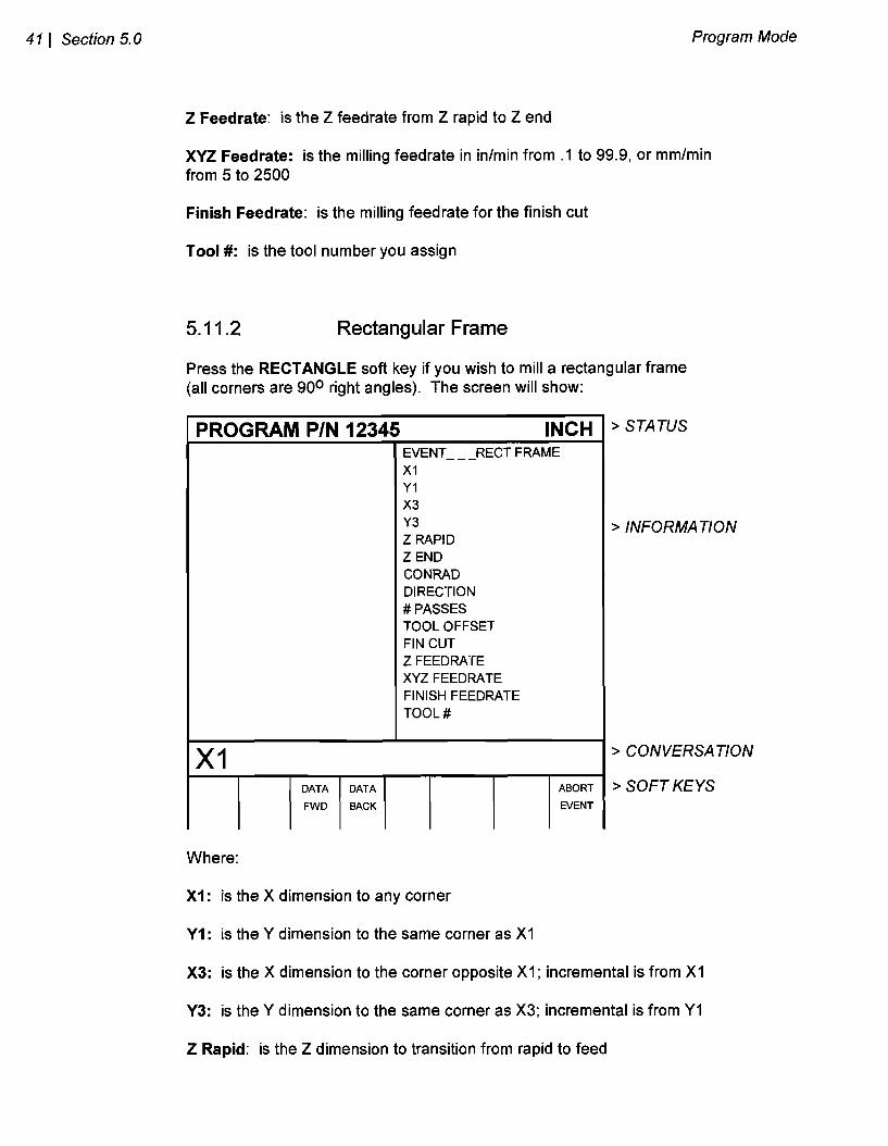
Step 4 - Select a Bolt Hole event and input the following data to center drill the holes:
Drill = I # Holes X Center Y Center Z Rapid Z End Radius Angle # Pecks Z Feedrate Tool #
1 5 0 abs 0 abs .O1 abs -. I0 abs 1.25 45. 1 5. 1 (tool 1 is the center drill)
Step 5 - Select a Subroutine (Sub) event and input the following data to drill the holes:
Select REPEAT First Event # Last Event # X Offset Y Offset Z Offset Z Rapid Offset # Repeats Tool #
1 1 0 0 -.2 (this -.2 added to - . I from the center drill is -.3 total) 0 1 2 (tool 2 is the .250 drill)
Step 6 - Select a Pocket event and input the following data to mill the .750 radius pocket:
Select CIRCLE X Center Y Center Z Rapid Z End Radius Direction # Passes Fin Cut Z Feedrate XYZ Feedrate Finish Feedrate Tool #
0 abs 0 abs .O1 abs -.2 abs .75 CCW 1 .01 2. 10. 5. 3 (tool 3 is a .500 end mill)

Program Mode Section 5.0 1 54
Step 7 - Select a Continue Mill event to rr~ill the outside perimeter.
Select ARC X Begin Y Begin Z Rapid Z Begin X End Y End Z End X Center Y Center Z Center Conrad Direction Tool Offset Z Feed rate XYZ Feedrate Tool #
0 abs -2.45 abs .O1 abs -.26 abs 0 abs 4.90 inc (or 2.45 abs) 0 inc 0 abs 0 abs 0 inc 0 Counterclockwise Right 2. 10. 3
Select Mill X End -3.064 abs Y End .5045 abs Z End 0 inc Conrad .841
Select Mill X End 0 abs Y End -2.45 abs Z End 0 inc Conrad Set
Select End Continue
Step 8 - Enter the Set Up Mode (see Section 7.0) and select TOOL DATA
a. lnput any diameter (e.g. .125) for TOOL # I - the center drill. b. Load the center drill into a tool holder and lower the quill to touch the
tool to the top of the part or some reference point. Press SET. Press DATA FWD to skip Modifier.
c. lnput .250 and SET for TOOL #2 diameter - the drill. d. Load the drill into a tool holder and lower the quill to touch the tool to the
same reference as in (b). Press SET. Press DATA FWD to skip Modifier. e. lnput .500 and SET for Tool # 3 diameter - the end mill. f. Repeat (d) for the end mill. g. Press RETURN

55 1 Section 5.0 Program Mode
h. Press REF POSN i. Move the quill near the top of its travel and SET to establish the Z
RETRACT position. j. Press RETURN. For this sample, we will allow X and Y HOME to be at
zero and we will not set any software travel limits.
Step 9 - Check your program by selecting TOOL PATH and pressing START
Step 10 - Follow the instructions in Section 8.2 to set X, Y, Z zero point and run the part.

SECTION 6.0- -=---=-
Edit Mode
Southwestern Industries, Inc. ProtoTRAK MX3 Programming, Operating & Care Manual

Edit Mode Section 6.0 1 57
6.0 EDlT MODE The ProtoTRAK MX3 allows for complete editing of programs including recall (and correction) of data, adding events in the middle of a program, deleting events within the program, and erasing programs.
6.1 Enter Edit Mode
Press MODE and select the EDlT soft key. The display will show:
> STATUS PROGRAM PIN 12345 INCH
SELECT
> INFORMATION
RECALL
> CONVERSATION
> SOFT KEYS
6.2 Recall and Data Correction
ADD
EVENT
If you wish to change, activate, or deactivate any of the General Program Options (see Section 5.1), select the PROG OPTION key.
To recall the data in your current program select the RECALL soft key. The conversation line will prompt "EVENT # asking for the event number you wish to review. Input the event number and SET. If you wish to change the part number, recall event 0. Assuming you requested Event 4, the display will show, for example:
PROG
OPTION
DELETE
EVENT
ERASE
PROG

58 1 Section 6.0 Edit Mode
> STATUS EDIT PIN 12345 INCH
> CONVERSATION
> SOFT KEYS
EVENT 3 BOLT
# HOLES 6
X CENTER 0.0000 abs Y CENTER 2.0000 abs
Z RAPID ,020 abs Z END -.75 abs RADIUS 0.8750
ANGLE 60.0000 # PECKS 2
Z FEEDRATE 4.0
TOOL # 1
Where:
EVENT 4 MILL
X BEGIN 2.4370 abs Y BEGIN 7.2950 abs Z RAPID 0 inc
Z BEGIN 0 abs X END 1.5000 inc
Y END 2.0000 inc
Z END -1.2 abs CONRAD NONE
TOOL OFFSET RIGHT
ZFEEDRATE 3.0
XYZ FEEDRATE 10.0
TOOL # 2
1 The event you recalled is shown with its data on the right side of the information area.
1 The previous event is shown to the left.
X BEGIN 2.4370 abs
1 The conversation line shows the first prompt for the selected event.
PAGE
FWD
1 The PAGE FWD (Forward) soft key indexes the event forward by one (from 3 and 4, to 4 and 5 in the above example).
1 The PAGE BACK soft key indexes the event back by one (from 3 and 4, to 2 and 3 in the above example).
PAGE
BACK
1 The DATA FWD (Forward) soft key steps the highlight and conversation line to the next prompt and data (Y Begin 7.2950A in the above example).
1 The DATA BACK soft key steps the highlight and conversation line to the previous prompt.
DATA
FWD
1 The EVENT # soft key allows you to input and recall another event without repeatedly paging.
1 The DATA END soft key jumps you to the last event prompt.
DATA
BACK
1 The RETURN soft key brings you back to the screen shown in Section 6.1.
EVENT
#
DATA
END
RETURN

Edit Mode Section 6.0 1 59
To correct any data, use the EVENT #, PAGE and DATA soft keys to get the data you wish to correct into the conversation line. Re-input and SET the correct data.
Note: Ifthe Feedrate is edited in any event it will automatically be edited in every subsequent and contiguous event with the same Tool number and feedrate. For example, let's say events 5 through 10, and 13 through 16 were all programmed with tool number 2, and 5 inches per minute feedrate. Ifyou edit the feedrate in Event 7 to 3 inches per minute, it will automatically change Events 8, 9, and 10 also. Events 5, 6, 13, 14, 15, and 16 will not be aflected.
If you request Event 0, the conversation line will display "Program Part Number" It may be changed if you wish.
6.3 Adding an Event
Events may be added to the program at the beginning, middle, or end of the program one event or Continue Mill at a time.
To do so, press the ADD EVENT soft key from the screen shown in Section 6.1. The conversation line will state "After Event #." lnput the event number which the event you wish to add will follow and press SET. The screen will ask you to "Select Event," and program as you normally would (as described in Section 5).
When an event has been added, all subsequent events will be renumbered accordingly. Appropriate adjustments will automatically be made to Subroutine events.
6.4 Deleting an Event
Events may be deleted one at a time or in continuous groups.
To do so, press the DELETE EVENT soft key from the screen shown in Section 6.1. The conversation line will state "Delete From #." lnput the first event number of the group to be deleted, and press SET. The conversation line will then read "Delete to # asking you to input the last event number of the group to be deleted, and press SET. If only one event is to be deleted, input its event number for both "Delete From # and "Delete To #."
When an event or group of events have been deleted, all subsequent events will be renumbered to eliminate any number gaps. All event numbers in any Subroutine event will also be renumbered.

60 1 Section 6.0 Edit Mode
6.5 Erasing a Program
You may erase your current program by pressing the ERASE PROG soft key shown in the screen in Section 6.1. However, if you ever wish to reuse this program, you must be certain that it has been saved on the ProtoTRAK MX3 floppy disk memory, or saved offline (see Section 10).
When you press the ERASE PROG soft key, the conversation line will be highlighted and state "ARE YOU SURE YOU WISH TO ERASE THIS PROGRAM?". If you are, press the YES soft key. If you are not, press the NO soft key. The display will return to the Select Mode screen shown in Section 6.1
6.6 Small Depth Adjustments
The tool offset procedure described in Section 7.2 is used to automatically input the differences in the various tool length offsets. The quill position is then automatically adjusted for these differences.
However, it is sometimes not possible to do this procedure with the required precision of your part. In addition, as tools wear they require more force to cut at the same rates which results in inaccurate depths on your part.
Section 7.2 also describes the procedure for inputting tool offset modifiers for each tool. These can be effectively used to make minor tool depth changes to correct for the above problems.

SECTION
Set Up Mode
Southwestern Industries, Inc. ProtoTRAK MX3 Programming, Operating & Care Manual

Set Up Mode Section 7.0 1 62
7.0 SET UP MODE The Set Up Mode is used to input tool diameter information and to visually check out a program.
7.1 Enter Set Up Mode
Press MODE and select the SET LIP soft key. The display will show:
Inputting Tool Data
SET-UP PIN 12345 INCH
SELECT
> STATUS
TOOL
DATA
> INFORMATION
> CONVERSATION
> SOFT KEYS
Every program has a corresponding Tool Table comprised of these three items:
SERV
CODES
TOOL
PATH
m Tool Diameter: used to calculate tool left or tool right adjustments
REF
POSN
Tool Offsets: used to adjust the quill (or ram for the DPM) for the length differences from one tool to the next
m Tool Modifiers: used to make small adjustments to the depth (Z rapid, Z begin and Z end) for each tool. This is actually a modifier to the tool offset above
Tool Diameters are saved and stored with the program but tool length offsets and modifiers are not. To enter tool information, press the TOOL DATA soft key. The display will show:

63 1 Section 7.0 Set Up Mode
> STATUS SET UP PIN 12345 INCH
TL# DlAM OFFSET ZMOD
1 0.0000 0.0000 0.0000 2 0.0000 0.0000 0.0000 3 0.0000 0.0000 0.0000 4 0.0000 0.0000 0.0000 7 0.0000 0.0000 0.0000
TOOL #I DIAMETER
> INFORMA TlON
PAGE
FWD
> CONVERSA TlON
>SOFT KEYS
Where:
RETURN PAGE
BACK
Each tool number that is in program 12345, as well as its diameter, and length offset and modifier are shown in the information area.
The conversation line shows the tool number for which you may input data. If that tool number already has a diameter, it will be shown in the conversation line and may be changed and SET.
DATA
FWD
The DATA FWD (Forward) soft key indexes the conversation from Tool Diameter, to Tool Offset, to Tool Modifier, to Tool Diameter for the next tool.
DATA
BACK
The DATA BACK soft key indexes the conversation back to the previous prompt for edit.
The PAGE FWD (Forward) soft key indexes the list forward if it is too long for one screen.
The PAGE BACK soft key indexes the list back if it is too lorlg for one screen.
The RETURN soft key brings you back to the Set Up Select screen in Section 7.1.
To input a tool diameter, when prompted enter the dimension and SET. To input a tool offset:
a. Load the tool into a fixed tool holder and insert in spindle.

Set Up Mode Section 7.0 1 64
b. Bring the quill down manually until the tool touches a fixed reference, e.g., the table, vice, part, etc.
c. Press SET. If this is for the tool in Event 1 the display will read "BASE". For any other tool it will automatically calculate and load the difference between that tool and the Base tool.
d. It is critical that every tool touch the same reference as b.
To edit a tool offset:
a. Enter SET UP mode and DATA FWD to the appropriate tool offset.
b. Load the new tool
c. Bring the tool down to the same reference used to set the tool originally.
To enter a tool length modifier, input the value when prompted and SET. For example, a -.005 modifier will make the part .005 inch deeper for all operations with this tool.
7.3 Reference Positio~is (REF POSN)
Appropriate reference positions can be input for each program. To do so, press the REF POSN soft key from the screen shown in Section 7.1. The display will show:
> STATUS SET-UP PIN 12345 INCH POSITION STATUS ZRETRACT SET X HOME 0 abs Y HOME 0 abs Z I-IMIT OFF X LIMIT OFF X LIMIT OFF Y I-IMIT OFF Y LIMIT OFF
SET RETRACT POS, PRESS SET
> INFORMATION
LIMITS ONlOFF
> CONVERSATION
> SOFT KEYS DATA FWD
DATA BACK
RETURN

65 1 Section 7.0 Set Up Mode
Where:
The information area shows the retract status (which has not been set), the home locations and software limits for all axes
The conversation line instructs you to move the quill to the Z retract position and press SET. It is strongly recommended that the Z retract position be set almost, but not quite all the way up. When the Z retract position has been set it will indicate so in the information area.
Note: Setting Z Retract is mandatory before a program may be run. Z Retract will always be 0.01 lower than the set value. This is to prevent the quill from hitting the upper travel limits.
X and Y home positions are where the table and saddle go when there is a tool change or at the end of the program. These dimensions must always be from absolute zero. Note Z home is the same as Z retract.
X and Y limit positions (one for plus direction, one for minus) will stop the program if they are exceeded during run. Note that pressing the LIMIT ONlOFF soft key will turn the prompted limit off, or back on to its input value.
DATA FWD (forward) soft key indexes the conversation to the next reference.
DATA BACK soft key indexes the conversation back to the previous reference.
7.4 Tool Path Graphics
The ProtoTRAK MX3 allows you to graphically show the tool path represented by your current part program. The path shown on the screen represents the center of the tool. All movements at a programmed feedrate are shown as a solid line. All rapid position paths are shown as broken lines and cross hairs.
To show the tool path, press the TOOL PATH soft key from Section 7.1. The display will show:

Set Up Mode Section 7.0 1 66
> STATUS
> INFORMATION
RUN PIN 12345 INCH
> CONVERSATlON
START
> SOFT KEYS
Where:
START: will draw the entire part scaled to fit within the screen drawing area. There will be a short delay while the ProtoTRAK MX3 computes the proper scale. Press and hold the START key for two seconds to rescale and reorient the path to its initial state if it has been adjusted (see Section 7.4.1)
SINGLE
STEP
SINGLE STEP: will draw one event one step at a time scaled to fit within the screen drawing area
SELECT
VIEW
SLOW: the same as START except the graphics will be drawn slowly so that you can see the process
SLOW RETURN
ADJUST VIEW: allows you to zoom, shift, and rotate the part view (see Section 7.4.1 below)
ADJUST
VIEW
SELECT VIEW: allows you choose between the XY, XZ, YZ, and 3D views of the part
RETURN: brings back the screen from Section 7.1
7.4.1 Adjust View
When you select the ADJUST VlEW soft key from above, the soft keys are relabeled:
SHIFT RIGHT
SHIFT UP
ZOOM PLUS
TOGGLE ROT RIGHT
RETURN ROT FWD

6 7 ( Section 7.0 Set Up Mode
and pressirrg the TOGGLE soft key shifts them back and forth from above to below:
Where:
SHIFT RIGHTILEFT: will shift the view (for the next start) of the path right or left by 10% per press
SHIFT UPIDOWN: will shift the view (for the next start) of the path up or down by 10% per press
TOGGLE SHIFT LEFT
ZOOM PLUSIMINUS: will expand or shrink the size of the graphics (for the next start) by 10% per press
RETURN ZOOM MINUS
SHIFT DOWN
ROTATE RIGHTILEFT (only if 3D view is selected): will rotate the viewing angle (for the next start) by 15 degrees per press. Note that a cube is superimposed over the screen to depict this view rotation
ROTATE FORWARDIBACKWARD (only if 3D view is selected): will rotate the viewing angle (for the next start) by 15 degrees per press. Note that a cube is superimposed over the screen to depict this view rotation
ROT LEFT
When the view has been properly adjusted, press the RETURN soft key and select START, SINGLE STEP, or SLOW to redraw the tool path with this new view.
ROT BACK
7.5 Service Codes
These are special codes which may be entered into the ProtoTRAK MX3 to call up routines used in installation checkout and service.
7.5.1 Sensor Calibration: Code 123
Occasionally it may be necessary to recalibrate the TRAK Sensor encoder accuracy. To do so, select the SERV CODES soft key from the screen in Section 7.1. The conversation line will prompt "CODE." Input 123 and press SET. The procedure is as follows:
a. The conversation line prompts "Select Axis." Press X, Y, or Z.
b. The conversation line prompts "Move to Standard Begin, then SET." Place a dial indicator in the spindle and move the table to touch off one

Set Up Mode Section 7.0 1 68
end of a standard or piece of material of known length. Press SET.
c. The conversation line prompts "Move to Standard End, then, SET." Move the table to touch off the other end of the standard. Press SET.
d. The conversation line prompts "Input Standard Length, then SET." lnput the length of the standard and press SET.
If a legitimate calibration is computed (actual divided by standard length), the system will automatically abort to the SET UP mode of operation. Repeat the entire procedure for each axis to be calibrated. If the calibration is not legitimate, the display will read "Unreasonable Calibration Factor." This occurs if the displayed readout in the calibration procedure was less than the standard length, or too much (the maximum allowable is 1 % more than the standard). Verify the standard, repeat the procedure, and request SWI or distributor service if needed.
7.5.2 Metric Default: Code 66
If you wish to have the ProtoTRAK MX3 power up in the metric measurement mode use the following procedure:
a. Press the SERV CODES soft key from the screen in Section 7.1
b. Press 66 SET when the conversation line prompts "CODE".
7.5.3 English Default: Code 67
If you wish to have the ProtoTRAK MX3 power up in the English measurement mode use the following procedure:
a. Press the SERV CODES soft key from the screen in Section 7.1.
b. Press 67 SET when the conversation line prompts "CODE"
7.5.4 Preset All Defaults: Code 99
If you wish to have all service defaults reset to those standardized at the factory use the following procedure:
a. Press the SERV CODES soft key from the screen in Section 7.1.
b. Press 99 SET when the conversation line prompts "CODE".

69 1 Section 7.0 Set Up Mode
7.5.5 Software ID: Code 33
If you wish to check the revision of the software in your ProtoTRAK MX3 use the following procedure:
a. Press the SERV CODES soft key from the screen in Section 7.1.
b. Press 33 SET when the conversation line prompts "CODE". The software identification will be shown in the Information area of the screen.
7.5.6 Variable vs. Fixed Depth Drill Pecking: Code 34
Variable depth drill pecking calls for the system to drill progressively less each peck. For example, for 3 pecks, 112 of the total is drilled the first peck, an additional 113 in the second, and the final 116 in the third.
Fixed depth drill pecking calls for the same amount in each cycle. For example, for 3 pecks, 113 in each cycle.
If you wish to switch from one peck routine to the other, use the following procedure:
a. Press the SERV CODES soft key from the screen in Section 7.1.
c. Observe the active routine in the conversation line.
b. Press TOGGLE to switch to the other routine or back.
7.5.7 Setting Z Backlash (TRAK DPM only)
See Section 5.17 in the TRAK DPM Installation, Operation, Maintenance and Safety Manual.
7.5.8 Select DNC Baud Rate: Code 37
If you have purchased the DNC option to run three-dimensional CADICAM programs via RS232, you may wish to alter the standard 4800 baud rate. Note that faster baud rates may allow you to run faster, but are subject to more error. Use the following procedure:
a. Press the SERV CODES soft key from the screen in Section 7.1

Set Up Mode Section 7.0 1 70
b. Press 37 when the conversation line prorr~pts "CODE". Select another baud rate from the soft key options, and press RETURN.
7.5.9 Adjust Following Error: Code 129
When the ProtoTRAK MX3 operates at high feedrates it may create small part machining errors as it goes around sharp corners. This exists on all CNC's and is commonly called a "following error." The ProtoTRAK MX3 is factory preset to allow a maximum following error of 0.001 inch. The feedrate will automatically be adjusted around sharp corners so as to not violate this limit.
You may adjust the maximum following error to a value as small as .0001 inch. However, the smaller the value, the slower the feedrate around corners.
To input a new Following Error use the following procedure:
a. Press the SERV CODES soft key from the screen in Section 7.1
b. Press 129 SET when the conversation line prompts "CODE"
c. Follow the instructions on the screen and input the Following Error value (from .0001 to .0100) and press INC SET.
7.5.10 Irregular Pocket Stepover: Code 140
In Irregular Pocket run, each machining pass cuts material equal to 71 percent of the tool diameter (this transfers into nearly 100% at certain corners). This represents a maximum cut or stepover.
This maximum stepover may be reduced by a factor from 1.0 (no change) to 0.1 (10 percent of the maximum). To input a new factor, use the following procedure:
a. Press the SERV CODES soft key from the screen in Section 7.1.
b. Press 140 SET when the conversation line prompts "CODE"
c. Input the new stepover factor and press INC SET.
7.5.11 EnableIDisable Z Jog: Code 202
Because of the very small quill travel for powered Z motion (this is not the case for DPM's) you may wish to disable the Z jog capability to prevent up or down crashes. To do so, use the following procedure:

71 1 Section 7.0 Set Up Mode
a. Press the SERV CODES soft key from the screen in Section 7.1
b. Press 202 SET
c. Note in the conversation line whether Z Jog is on or off. Press the TOGGLE soft key to switch. Press RETURN.
7.5.12 Save Calibration Constants to System Disk: Code 142
Calibration constants (for sensors, ball screws, etc.) and certain system configuration data are stored in the ProtoTRAK MX3 computer EEPROM memory chips. This Service Code allows you to copy these parameters to your system disk. The value of this is that if you have a computer module failure, your serviceman can copy the parameters from the disk back into the corrected computer memory without recalibrating the entire machine tool.
To save the calibration constants to the system disk, use the following procedure:
a. Press the SERV CODE soft key from the screen in Section 7.1.
b. Press 142 SET when the conversation line prompts "CODE".
c. Read the instructions and press the YES soft key if you wish to execute the operation. Press NO if you do not.

SECTION 8.0
Program Run Mode
c ProtoTRAK MX3 Programming, Operating & Care Manual

Program Run Mode Section 8.0 1 73
8.0 PROGRAM RUN MODE 8.1 Enter Run Mode
Press MODE and select the RUN soft key. 'The display will show:
> STATUS RUN PIN 12345 INCH
SELECT
> INFORMA'TION
START
> CONVERSATION
> SOFT KEYS START
EVENT #
8.2 Starting to Run
TRlAL
RUN
Before running a part, you need to establish the position relationship between the part and quill. That is, you need to identify where the part is on the table relative to the tool or quill centerline.
This is done by using an edge finder or dial indicator to move the table so that the part program absolute zero is under the quill centerline. ABS SET this position as absolute zero in the DRO mode. In addition, load the tool for Event 1 and position it at Z absolute zero. If this is impossible, position the tool some known distance above absolute zero and ABS SET this dimension.
The program may be started in the two ways identified as soft keys in the screen in Section 8.1
Pressing the START soft key begins the program at Event 1 and assumes that the absolute zero that was last set in the DRO mode corresponds to the part program zero. That is, if you were in the DRO mode and you moved the table to X=O ABS, and Y=O ABS the part program zero would be directly under the quill centerline. This start does not reset your absolute zero.

74 1 Section 8.0 Program Run Mode
Pressing the START EVNT # soft key allows you to start in the middle of a program. This kind of start will not reset the absolute position. When you press the START EVNT # soft key, the conversation line will prompt "Input Event #." lnput the number of the first event you wish to run, and press SET. If the START EVNT # is a Repeat or Rotate, the conversation line will prompt "Starting Repeat Number" asking which repeat or pass you wish to start.
8.3 Program Run
When you have started by any of the means above, the display will show:
> STATUS
> INFORMATION
RUN PIN 12345 SERVOS ON INCH EVENT 0 0 1 BOLT HOLE
X 0.0000 ABS Y 0.0000 ABS Z 0.0000 ABS FEEDRATE = 0.0 OVERRIDE = 100%
LOAD TOOL I DIA: --- > CONVERSATION
> SOFT KEYS SHOW
ABS
Where:
The part number being run is shown in the status line.
SHOW
INC
A "SERVOS ON" message will appear in the status line when the servo motors are turned on.
A "SIF" message will appear in the status line when the Scale Factor is not set at 1.0000 (see Section 5.1).
SHOW
PATH
The event number and type being run is shown at the top of the information area.
SHOW
PROG
The current X, Y, Z absolute positions are shown in the information area.
The programmed Feedrate is shown at the bottom of the information area.
The current Feedrate Override % (as controlled by the FEED qt and FEED r(r keys) is shown at the bottom of the Information Area.

Program Run Mode Section 8.0 1 75
H The conversation line will show all appropriate messages (see Section 8.4).
H The SHOW ABS soft key (which is automatically assumed if one of the other 3 show keys are not selected) will show the absolute X, Y, Z positions as the part is run.
H The SHOW INC soft key will show the incremental (or distance to go within the event) X, Y, Z positions as the part is run.
H The SHOW PATH soft key will show the tool path graphics as the part is run. You should always perform the tool graphics in the Set Up Mode (see Section 7.4) to properly size the part for this Show Path option.
H The SHOW PROG soft key will show the programmed data for the event being run, and the next event as the part is run.
The run procedure is very simple. Follow the instructions on the conversation line and proceed by pressing the GO key.
8.4 Program Run Messages
During Program Run, all messages which will help you to run the part will appear in the conversation line. The messages you will usually see are:
Load Tool : Means to load the tool requested and press GO to continue.
Run Over: Means that the program run is complete. If you are running a second part which will be fixturedlclamped in the exact same position as the first part, you do not need to relocate the absolute 0 and restart. Instead, press the NEXT PART soft key when the conversation line states "Run Over" and the system will proceed directly to Event 1 when you press GO.
8.5 Stop
At any time, the program may be halted by pressing the STOP key. This freezes the program at that point. To continue, press the GO key.
8.6 Feedrate Override
The run feedrate may be changed at any time by pressing the FEED + or FEED r(r keys. Each press modifies the programmed feedrate, as well as rapid by 10%.

76 1 Section 8.0 Program Run Mode
8.7 Trial Run
Trial Run allows you to quickly check out your program with no Z movement before you actually start to make parts. In trial run the table will move at rapid speed regardless of what feed rates are programmed (the rapid speed may be overidden with FEED + and FEED Sr keys). The table will stop at each "stop" location (for example, at each drill location) but immediately continue on without your input.
To do a trial run, press the TRIAL RUN soft key from the screen shown in Section 8.1. The conversation line will read 'Check Table and Z, then Press GO." Be certain the table is positioned so that if it moves through the part program, it will not reach its travel limit. Also check that the quill is fully retracted. Press GO to begin.
8.8 Data Errors
The Program Mode in Section 5 describes several rules which must be followed to successfully program a part. In addition, a program must make sense geometrically. For example, you can't machine a .250 inch diameter circular pocket using a .500 inch end mill.
Data errors will nearly always be detected when the ProtoTRAK MX3 runs through a program--either as a Trial Run or on an actual part run. They may also be detected in the Set Up mode when using the Tool Path Graphics routines.
Whenever the ProtoTRAK MX3 detects a data error the display will chauge to a screen typified by the example below.
EXPLANATION The programmed arc or circle is a point. XY begin, end, center are the same.
SOLUTION Check all XYZ dimensions.
Data Error 5013 around event 21
RETURN
> STATUS
> INFORMATION
> CONVERSATION
> SOFT KEYS
The Conversation Line displays the error number (you may wish to record this number for troubleshooting purposes) and the event where the error was

Program Run Mode Section 8.0 1 77
detected. This is not necessarily the event which is in error since the system often "looks ahead" to make sure there is compatibility from one event to another.
In addition, an explanation is given for each data error type as well as a suggested solution. Press the RETURN soft key to go back to the Select Mode screen, correct your error, and proceed.
8.9 Fault Messages
The ProtoTRAK MX3 performs a number of automatic checks or self- diagnostics. If problems are found it will signal you through the display. The conversation line will display "Fault ". The information area will display an explanation and suggested solution. Press the RETURN key to get back to the Select Mode screen.

78 1 Section 8.0 Program Run Mode

SECTION
Math Help Mode
Southwestern Industries, Inc. ProtoTRAK UX3 Programming, Operating & Care Manual

Math Help Mode Section 9.0 1 80
9.0 MATH HELP MODE Prints are, unfortunately, not always drawn and labeled in such a way as to provide all of the points necessary for programming. To minimize this problem, the ProtoTRAK MX3 provides a graphic math help function which can be used to automatically calculate points of intersection, centers of arcs, trig functions, square roots, etc.
9.1 Procedure
To enter the Math Help Mode, press MODE and select the MATH HELP soft key. The screen will show:
> STATUS SET-UP INCH A Line-Line lntersection B Line-Arc lntersection C Arc-Arc lntersection D Line-Arc Tangency E Centers, Points, Radius, Angles of Circles F Polar-Cartesian and Other G Calculator-Math/Trig
SELECT
> INFORMATION
A
> CONVERSATION
> SOFT KEYS B
If you already know the math help type you want (see Section 9.3) press the TYPE # soft key and enter the number and SET.
If you do not know the type, select from A through G using the soft keys.
C
If, for example, you wish to find the intersection of a straight line and an arc or circle, press the B soft key. The screen will show:
D E F G TYPE#

81 1 Section 9.0 Math Help Mode
> STATUS MATH Line-Arc Intersection INCH
TYPE 13 Find the intersection of a line and an arc when 2 points are known on the line, and the arc's center and radius are known
TYPE 14 Find the intersection of a line and an arc when 2 points are known on the line, two points are known on the arc, and the arc radius is known
SELECT
> INFORMATION
13
> CONVERSATION
> SOFT KEYS 14
If the information you know about the line and arc correspond to Type 13, then select the 13 soft key. The screen will then show:
RETURN
> STATUS
> INFORMATION
MATH Line-Arc Intersection INCH
TYPE 13
X I Y1 X2 Y2 X CENTER
R1
X I > CONVERSATION
DATA
FWD >SOFT KEYS
Input the known data in the same way you would program an event. When all of the data is entered, the solution (or solutions if there are more than one) will be shown on the left side of the information area.
DATA
BACK
There are often multiple solutions for geometry problems. For example, in the Type 13 example above, a line will often intersect an arc or circle in two
ABORT EVENT

Math Help Mode Section 9.0 1 82
places. In these cases all possible solutions will be calculated and displayed. In most cases a careful inspection of the print and some common sense will tell you which solution applies to your problem.
9.2 Calculator-Math and Trig Procedures
If you select soft key G from the first screen in Section 9.1, the display will show:
> STATUS MATH Calculator-MathRrig INCH
> INFORMATION
+
> CONVERSATION
> SOFT KEYS
Use the soft keys like a simple calculator, but always press = for each calculation. Press RSTR to Clear Entry. For example, for
-
press 3 + 9 = - 2 = x 27 = 14.5 = to get the correct answer = 60
To calculate a square root, press RSTR, the number you wish to find the square root of, and the SQUARE ROOT soft key.
x
To perform trigonometry functions, press the TRlG soft key. The display will show:
1 SQUARE
ROOT
= TRIG RETURN

83 1 Section 9.0 Math Help Mode
> STATUS
> INFORMATION
MATH Calculator-MathITrig INCH
> CONVERSATION
SlNE
> SOFT KEYS
To calculate the sine, cosine or tangent of an angle, input the angle in degrees and press the SINE, COS or TAN soft key.
To calculate the arcsine, arccosine, or arctangent of a number, input the number and press the ARC SINE, ARC COS or ARC TAN soft key to compute the angle in degrees.
COS
Press TRIANGLE to find unknown angles or side lengths of a (90 degree) right triangle. The left side of the screen shows a right triangle with sides A,B, C and angles G and H. Simply input the data you know, and when the ProtoTRAK MX3 knows enough it will automatically show the rest.
TRI-
ANGLE
9.3 Math Help Types
TAN
RETURN
A. Line-Line Intersection
Type 10 : Find the intersection of 2 lines when any 2 points are known on each line.
ARC
SlNE
Type 11 : Find the intersection of 2 lines when 2 points are known on one line, one point is known on the other line, and the angle between the lines is known.
Type 12: Find the intersection of 2 lines when 2 points are known on one, one point is known on the other, a radius tangent to both lines is known, and when one of the points on the two known point lines is also on the radius.
ARC
COS
ARC
TAN

Math Help Mode Section 9.0 1 84
B. Line-Arc lntersection
Type 13: Find the intersection of a line and an arc when 2 points are known on the line and the arc's center and radius are known.
Type 14: Find the intersection of a line and an arc when 2 points are known on the line, 2 points are known on the arc, and the radius is known.
C. Arc-Arc lntersection
Type 15: Find the intersection of 2 arcs when the center and radius of each are known.
D. Line-Arc Tangency
Type 16: Find the intersection of a line tangent to 2 arcs when the centers and radii of each are known. Line does not cross centers.
Type 17: Find the intersection of a line tangent to an arc when one point is known on the line and the arc's center and radius are known.
Type 18: Find the intersection of a line tangent to 2 arcs when the centers and radii of each are known. Line crosses centers.
Type 19: Find the intersection of an arc tangent to 2 other arcs when the centers and radii of the 2 are known, and the radius of the first is known.
E. Centers, Points, Radius and Angles of Circles
Type 20: Calculate the center of an arc when 2 points on the arc and its radius are known.
Type 21: Calculate a point on an arc when the center, another point on the arc, and the angle between the arc points are known.
Type 22: Calculate the radius of an arc or circle when one point on the arc and the center are known.
Type 23: Calculate the center of an arc or circle when 2 points on the arc and the angle between them are known.
Type 24: Calculate the center and radius of an arc or circle when 3 different points on the arc or circle are known.

85 1 Section 9.0 Math Help Mode
F. Polar-Cartesian, Other Type 25: Calculate the cartesian (X and Y) location when the polar (R and angle) coordinates are known.
Type 26: Calculate the decimal angle from an angle given in degrees, minutes, and seconds.
Type 27: Calculate an accurate XY center as close to the given XY center as possible.

SECTION
- . 10.0 Program Inlout Mode
Southwstern Industries, Inc. ProtoTRAK MX3 Programming, Operating, & Care Manual

Program In/Out Mode Section 10.0 / 87
10.0 PROGRAM INIOUT MODE You may store and retrieve programs in two different ways:
1. The ProtoTRAK MX3 has two built-in floppy disk drives. One holds the system's operating software and is not accessible. The other is accessible through a door in the computer cabinet and can store 192 moderate size programs.
2. You may store and retrieve programs through an RS232 link to most computers. The RS232 port is located on the back of the pendant box. This same link is used to load programs which have been written via a CADICAM system.
All programs are transmitted through the ProtoTRAK MX3's current or computer program memory. Programs are sent from the computer memory (that is, a current program) to one of the above two permanent memory locations. Or programs are retrieved from one of the two, and loaded into the ProtoTFWK MX3's computer memory. Programs may not be sent directly from one of the above two storage devices to another.
10.1 Cautions About Storing and Retrieving Programs
Care must be taken to keep from losing a program you wish to keep. This can happen two ways.
First, whenever a program is retrieved, it is loaded into the ProtoTRAK MX3's computer program memory. When this happens, your existing current program is erased. Therefore, if your current program is one you want to keep, be certain to store it before you retrieve another program.
Second, to store a program it must have a part number so that the ProtoTFWK MX3 can find it if you want it retrieved. However, no two programs can have the same part number (how would the system decide which to retrieve?). Therefore, if you store a program with any particular part number, it will automatically erase any other program with that same part number.

88 / Section 10.0 Program In/Out Mode
10.2 Program Formats And Labeling
The ProtoTRAK MX3 has its own unique programming system--one that organizes the program into events rather than codes and blocks. Most CADICAM sytems output their programs in an RS274 format--commonly referred to as a G-code format.
The ProtoTRAK MX3 software will accept an RS274 CADICAM generated program (as configured through a post processor similar to a Fanuc 6) and convert it to a ProtoTRAK MX3 event type program. This can occur by directly downloading the program through an RS232 connection from your personal computer to the ProtoTRAK MX3 (see Section 10.6) or by transferring your personal computer floppy disk directly to the ProtoTRAK MX3 accessible floppy disk drive.
10.3 Enter Program Inlout Mode
Press MODE, and select the PROGRAM INlOUT soft key. The display will show:
> STATUS PROG INIOUT INCH
SELECT PROGRAM STORAGE DEVICE
> INFORMATION
MX3 FLOPPY
> CONVERSATION
> SOFT KEYS
Where:
MX3 FLOPPY: selects the ProtoTRAK MX3's built-in floppy disk drive
RS232: selects a computer via the RS232 port
RS232
DNC: selects the optional DNC capability
DNC

Program In/Out Mode Section 10.0 / 89
10.4 Storing and Retrieving Programs from the ProtoTRAK MX3 Built-In Floppy Disk Drive
When you select the MX3 FLOPPY soft key from the screen shown in Section 10.3, the display will show:
> STATUS PROG INIOWT ProtoTRAK MX3 INCH
1. MX3 6. MX3
24. MX3 97. MX3
132. MX3 841. CAM
2492. MX3 8725. CAM
150292. MX3 8197 MX3
87132. MX3 252841. CAM
PART NUMBER 12345
> INFORMATION
STORE
> CONVERSATION
> SOFT KEYS
Where:
RETRV
MX3
All part numbers in the ProtoTRAK MX3 floppy disk are listed in the Information Area. The listing shows the part numbers followed by .MX3 if they were programmed through the ProtoTRAK MX3, or followed by CAM if they were programmed through a CADICAM system.
H The part number of the current program is shown in the conversation line.
The PAGE FWD (Forward) soft key will continue the part number list if there are too may to be shown on the screen.
RETRV
CAM
The PAGE BACK soft key will shift back the part number list if there are too many to be shown on the screen.
PAGE
BACK
H The RETURN soft key will bring back the screen in Section 10.3.
RETURN
ERASE
Note: All programs written on a ProtoTRAK M3 or TRAKA.G.E. 3 CNC are also labeled with a .MX3 so that they are completely compatible with programs written on this ProtoTRAK MX3.
PAGE
FWD

90 / Section 10.0 Program In/Out Mode
If you wish to store a program:
a. Check the part number shown in the conversation line. It may be edited by inputting the part number you wish.
b. Press the STORE soft key. The stored part number will be added to the list.
If you wish to retrieve a program:
a. lnput the part number so it is shown in the conversation line. Be certain it is a part number in the list.
b. Press the RETRV MX3 soft key if the part is labeled as one generated by the ProtoTRAK MX3 or ProtoTRAK M3 or TRAK A.G.E. 3. This program will now be your current program.
c. Press the RETRV CAM soft key if the part is labeled as one generated with a CAM (see Section 10.6). This program will now be your current program.
If you wish to erase a program from the list:
a. lnput the part number so it is shown in the conversation line. Be certain it is a part number in the list.
b. Press the ERASE soft key. The program will be permanently erased from the floppy disk and the part number will be eliminated from the list.
10.5 Backing Up Your Programs
It is strongly recommended that important programs not be solely stored on the ProtoTRAK MX3 accessible floppy disk drive. A back-up may be made in two ways:
a. Remove the accessible floppy diskette (in the bottom drive) which holds the part programs and, using an IBM compatible computer, make a copy or store the data on its hard drive.
b. Use the RS232 link (see Section 10.6) to transfer programs to your computer for storage.
If at any time you feel the program data on the ProtoTRAK MX3 floppy diskette is lost or damaged, use your back-up to reproduce the programs.

Program In/Out Mode Section 10.0 / 9 1
10.6 Storing and Retrieving Programs through the RS232 Port - Including CADICAM Generated Programs
If you wish to use the RS232 port to communicate between your ProtoTRAK MX3 and your computer, call the Service Department at Southwestern Industries and let us know what computer you wish to interface to. The telephone number is 8001367-31 65.
You will be sent the necessary equipment and installation instructions at no cost. Please be certain the installation is correct before attempting to use the RS232 Store and Retrieve functions.
When you select the RS232 soft key from the screen in Section 10.3, the display will show:
> STATUS PROG INIOUT RS232 INCH
PART NUMBER 12345
> INFORMATION
STORE
> CONVERSATION
> SOFT KEYS
Where:
RETRVE MX3
The part number of the current program is shown in the conversation line.
The RETURN soft key will bring back the screen in Section 10.3.
RETRVE CAM
If you wish to store a program:
RETURN
a. Be certain the program you wish to store is in the ProtoTRAK MX3 current or computer memory. It does not matter what part number is shown since the stored part number is assigned at the personal computer (see "d" below)
b. Be certain the communication port of the computer is properly configured. For IBM PC compatible computers, at the DOS prompt type MODE COMA :4800,e,7,1

92 / Section 10.0 Program In/Out Mode
c. At the computer, type COPY COMI, the program part number, and the "ENTER" key. For example, COPY COMI 12345, then press ENTER. If you have a computer that is not IBM compatible, use the standard receive message.
d. At the ProtoTRAK MX3 press the STORE soft key. The program will be written to the floppy disk, and the conversation line will read "STORING." When complete, the screen will revert to the one shown in Section 10.3
If you wish to retrieve a program:
a. Input the part number you wish the program to be assigned in the ProtoTRAK MX3.
b. Press the RETRVE MX3 soft key if the program you wish to retrieve is in the ProtoTRAK MX3 or ProtoTRAK M3 or ProtoTRAK A.G.E. 3 event type format. Press the RETRVE CAM soft key if the program you wish to retrieve is in the CADICAM, RS274, G-code format.
c. Be certain the communication port at the computer is properly configured. For IBM PC compatible computers, at the DOS prompt type MODE COMI :4800,e,7,1
Note: Ifyou write a program using a CAD/CAM system on your computer and intend to enter it into the ProtoTRAK MX3 via the RS232 port, you must name the program with one to eight numerical digits followed by a decimal point, followed by CAM for example, 123. CAM or 87654321. CAM). I f these rules are not followed the ProtoTRAK MX3 will not recognize the program.
d. At the computer, type COPY, the program part number, COMI and the ENTER key. For example, COPY 12345.MX3 COMI, then press ENTER. If you have a computer that is not IBM compatible, use the standard send procedure.
e. When the program has been completely received by the ProtoTRAK MX3 the screen will revert to the one shown in Section 10.3
Note: Do not attempt to write ProtoTRAK MX3 formattedprograms through your CAD/CAMprogramming system.

SECTION
Service
Southwestern Industries, Inc. ProtoTRAK MX3 Programming, Operating & Care Manual

Service Section 11.0 1 94
11.0 SERVICE 11.1 Tramming The Head (not for 'TRAK DPM)
The ProtoTRAK MX3 Z axis bracketry is designed to provide a rigid attachment between the ballscrew and the head. In addition, this bracketry allows you to retram or swivel your head without disturbing the ballscrew-to-head alignment. The procedure is as follows (refer to drawing):
1. Remove the cover from over the ballscrew.
2. Loosen the two socket head couplings on the left which replaced the standard left side hex nuts used to hold the head. Loosen the two hex head cap screws on the right side (Item 20).
3. Using a small allen wrench in the holes, loosen the two leveling nuts on the right (Item 16).
4. Loosen the two jackscrew nuts on the right (Item 14).
5. Swivel or tram the head as you normally would.
6. Tighten the two jackscrew nuts (Item 14) on the right, and the two socket head couplings on the left to approximately 25 ft. Ib. in a crisscross pattern. Then tighten to 50 ft. Ib. or to the manufacturer's specification in the same crisscross pattern.
7. Move the leveling nuts (Item 16) on the right up against the back of the base plate and lightly tighten the two socket head screws (Item 20) into the jackscrew nuts.
8. Ensure that the quill moves smoothly up and down. If not, use a bubble level on the front of the quill and on the front of the base plate to adjust the base plate parallel with the quill. Readjust the leveling nuts on the right as necessary to achieve this. Always lightly tighten the two socket head screws (Item 20) before checking the base plate with the bubble level.
If the quill still does not move smoothly, raise the quill all the way up, loosen the two cap screws (Item 9), move the quill up and down, raise the quill up, and retighten the cap screws.
9. Tighten the two socket head screws (Item 20) to 50 ft. Ib. and recheck quill smoothness. Repeat 8 above as necessary.
10. Replace the front cover

95 1 Section 11.0
ProtoTRAK MX3 Z Axis Drive Assembly
I PARTNO. I DESCRIPTION 1 - # J I E l 112-13X 1.75
1 16267 I Motor Assarnblv 1 10 I 1 1/4-20~3/4. 1 Socket Head Cap Screw 1 12
1 l6210 1 Positioner locator " I 13 I 1 16213-13 1 1/2-13JaCksCtewNut 1 14
I PART Nos I DESCRlPnON I ITEM# I 1 16216 I Hex Head Screw 1 15 I I Z S ~ S I Fork 1 1 1 1 16214 1 31h16 Levalinq Nut 1 16 1 I l83%5-1 1 31824 Bra&et Ballnut Mountinq Bolt 1 7 1 1 318' I Fat Washer 1 17 I 1 - I 318 Lock Washer l 3 1 1 - I 318-1 6 Hex Nut 1 18 1 1 9064QA179 1 ll-W0 mastic Nut Lock 1 4 1 1 1 4 9 3 2 I Lame Aanae Washer 1 19 I 1 1 559 1 flat Washer I 5 I 1 la -1 3x1 112' 1 Socket Head Cap Screw I 20 1 1 1/4-20x3/8' 1 Socket Head Caw Screw 6 / 1 91079A036 1 Jam Nut 1 21 1 I lIC20X1 314' 1 Scckst Head C ~ D Screw 1 7 1 1 9 8 A O 0 1 I lelBO I MX3 -Cable 1 8 I I I 1.79 1

SECTION
MX2e Operations
Southwestern Industries, Inc. ProtoTRAK MX3e Programming, Operating & Care Manual

MX2e Operations Section 12.0 1 97
12.0 MX2e OPERATIONS For most operations, using the MX2e control is very similar to using the MX3e and, therefore, does not require explanation in this manual.
The following operations are either unique to the IMX2e; or for some other reason are not obvious to the operator that has already learned the MX3e.
12.1 Teach
The Teach function allows you to input a program in the ProtoTRAK MX2e while in the DRO mode, remembering rapid position and feed rate milling events as you machine the first part, or portion of a part. (Note: Teach may be used only in the ProtoTRAK MX2e.)
This can be useful for simple operations like facing off a part, clearing out excess material, or remembering a few hole locations. While Teach can be useful, it is definitely not a'substitute for programming the ProtoTRAK MX2e which is very simple, very powerful, and much more useful.
To enter Teach, press the TEACH soft key from the screen in the DRO Mode. The display will show:
> STATUS DRO INCH
X 0.0000 INC Y 0.0000 INC Z 0.0000 INC
> CONVERSATION
> SOFT KEYS SAVE
POSN
The SAVE MlLL soft key will only be activated once an initial position event has been saved.
ERASE
TEACH RETURN SAVE
MILL RUN
TEACH

98 ( Section 12.0 MX2e Operations
12.1.1 Making a Teach Program
Only one Teach program can be contained in the ProtoTRAK MX2e at any given time. If an existing Teach program is not first erased (see below), more "teaching" will simply add events or moves on to the end of the existing program.
Teach programs are made up of Position events, or moves, and Rllill events. Position events are moves at rapid speed and are used to go to the beginning point of a milling move, or to position over a point like a hole for drilling. Mill events are straight line milling moves in the X or Y, or both directions at an input feedrate.
To make a Teach program, follow these procedures:
a) The first event must be a Position move. Crank the X and/or Y handles to the desired position and press the SAVE POSN soft key. This point will be memorized. During Teach Run the machine will move at rapid speed to this location and stop.
b) If you wish to rapid to the next location, repeat (a). If you wish to feed or mill, go to (c).
Mill the part along the X or Y (or both) path(s) using the hand cranks. It's not important how you get to the end point. In Teach Run the machine will move at the programmed feedrate in a straight line from the beginning point to the end. When at the end point, press the SAVE MILL soft key. The conversation line will prompt "Feedrate 10.0." You may change the feedrate from the 10'inches per minute default to any value you wish through the numeric keyboard. When the feedrate is what you want, press INC SET or ABS SET to load this position and feedrate into memory.
d) Repeat (a) and (c) above for all other rapid Position events, or feed Mill events you wish.
e) In Teach Run the machine will continue from one Mill event directly along to the next Mill event. You must program a SAVE POSN if you want the machine to stop.
f) All events will automatically be saved with Tool Number 99.
g) All lblill events will be saved with TOOL Center Offset.

MX2e Operations Section 12.0 ( 99
12.1.2 Running a Teach Program
A Teach Program may be run by itself from the DRO Mode, or added to a regular program (see below) and run in the normal Run Mode.
To run a Teach program, press the RUN TEACH soft key from the screen in Section 12.1 above. Follow the same procedure for running a regular program.
Note: When you use Position to go to the beginning of a Mill moue, you will have to hit GO twice to begin the milling moue.
12.1.3 Erasing a Teach Program
The ProtoTRAK MX2e may contain only one each Program. To input another, you must first erase the one that exists.
To do so: Press the ERASE 'TEACH soft key from the screen in Section 12.1, then select the YES soft key.
12.1.4 Adding a Teach Program to an lnput Program
A program generated from Teach in DRO Mode may be inserted into a regular program in the Edit Mode. You must have at least a one event program to add the Teach events.
To do so, press the ADD TEACH soft key from the Edit screen. The conversation line will state "After Event #". lnput the event number which the Teach program or events will follow, and press SET. You may edit this data as you would in any other event.
All Teach events will be added as normal Position or Mill events with CONRAD=O, Tool Offset=Center, Feedrate as set in Teach, Tool #99 and a Continue=Yes between successive Teach Mill events.
When the Teach events have been added, all subsequent events will be renumbered accordingly. Appropriate adjustments will automatically be made to Subroutine events.
The major portion of some jobs can best be done manually with DRO. However, there are often just a few cuts that require excessive time or

100 1 Section 12.0 MX2e Operations
complicated set-up, for example, arcs or diagonals. DO ONE programming assists you in performing these more difficult operations in the DRO Mode without the necessity of complete programs.
DO ONE events may only be programmed and run one at a time. When a DO ONE event has been run, it is erased from the ProtoTRAK MX2e memory.
The incremental reference position for any DO 0N.E event is the current position of the tool (or actually the table and saddle). That is, the position at the time the event is run. So, an incremental input will move the table by that amount from where it currently is. The absolute reference is unchanged. DO ONE programming is nearly identical to complete part programming with these differences.
a) Press the DO ONE soft key in the DRO Mode to activate this routine.
b) You do not have to program a tool number. Since the program has only one event, you need only one tool.
c) You will be prompted for tool diameter during DO ONE programming. Therefore, you do not need to enter SET UP Mode.
d) DO ONE Mill and Arc Events will not prompt for CORNAD. There is no second event to connect to.
e) There cannot be a DO OWE A.G.E. Profile event.
f) There cannot be a DO ONE Subroutine event,
g) You cannot draw a DO ONE part or tool path in Set-Up Mode, or with the LOOK key.
When the DO ONE event is complete, press START to run the 'DO ONE.
12.3 Z Jog
For MX3e systems retrofit to a manual knee mill, the jog command will not automatically be activated for operation of the Z (quill). In order to activate the jog for Z, enter Special Code 202 in the Set Up Mode.
In the MX2e the prompts for Z positions and feedrates are excluded. ,This results in much easier programming.

MX2e Operations Section 12.0 1 101
12.5 Graphics
Part graphics in the MX2e are always in two dimensions showing the X/Y plane.
12.6 Running a Two-Axis Program
When running a two-axis program, it is recommended that the Z axis DRO be used to machine Z depth. The Z readout may be put into INC or ABS measurement independently from the X and Y depending on your convenience. See Sections 4.4 to 4.9 for more information on operating the DRO function.
In the Run MODE the "Step Z Up" and "Step Z Down" are provided for DPM operation as a convenient way to position the Ram for different tools. This function is useful because the DPM lacks a mechanical ram crank. Each press of the "Step" key will move the ram up or down one inch at rapid speed.

Trav-A-Dial & TRAK Warranty Policy
Warranty
Trav-A-Dial and TRAK products are warranted to the original purchaser to be free from defects in workmanship and materials for the following periods:
Product Warranty Period p New Trav-A-Dial 1 Year I Year New TRAK Any EXCHANGE Unit
1 Year 1 Year 90 Days 90 Days
The warranty period starts on the date of the invoice to the original purchaser from southwestern Industries, inc. (S WI) or their authorized distributor.
If a unit under warranty fails, it will be repaired or exchanged at our option for a properly functioning unit in similar or better condition. Such repairs or exchanges will be made FOB Factory/Los Angeles or the location of our nearest factory representative or authorized distributor.
Disclaimers of Warranties
This warranty is expressly in lieu of any other warranties, express or implied, including any implied warranty of merchantability or finess for a particular purpose, and of any other obligations or liability on the part of SWI (or any producing entity, if different).
Warranty repairslexchanges do not cover incidental costs such as installation, labor, freight, etc.
SWI is not responsible for consequential damages from use or misuse of any of its products.
Trav-A-DiaFTRAK products are precision mechanicaVelectromechanical measurement systems and must be given the reasonable care that these types of instruments require:
Replacement of chip scrapers and wipers is the responsibility of the customer. Consequently, the warranty does not apply if chips have been allowed to enter the mechanism.
Accidental damage, beyond the control of SWI, is not covered by the warranty. Thus, the warranty does not apply if an instrument has been abused, dropped, hit, disassembled or opened.
Improper installation by or at the direction of the customer in such a way that the product consequently fails, is considered to be beyond the control of the manufacturer and outside the scope of the warranty.