
Programme Area: Energy Storage and Distribution Project ...
80
Title: The report defines the approach for analysing the longer term role for storage. This includes a literature review of existing approaches and a proposal for a modelling approach for analysis in Stage 2. Context: This project will develop energy system modelling capability to increase understanding of the role of energy storage and system flexibility in the future energy system. The modelling capability will provide a whole systems view of the different services that could be provided and at which points in the energy system they are most appropriate. Management consultancy Baringa Partners are delivering this new project to develop the capability to improve understanding with regards the future role of energy storage and the provision of cross-vector system flexibility within the context of the overall UK energy system. Disclaimer: The Energy Technologies Institute is making this document available to use under the Energy Technologies Institute Open Licence for Materials. Please refer to the Energy Technologies Institute website for the terms and conditions of this licence. The Information is licensed ‘as is’ and the Energy Technologies Institute excludes all representations, warranties, obligations and liabilities in relation to the Information to the maximum extent permitted by law. The Energy Technologies Institute is not liable for any errors or omissions in the Information and shall not be liable for any loss, injury or damage of any kind caused by its use. This exclusion of liability includes, but is not limited to, any direct, indirect, special, incidental, consequential, punitive, or exemplary damages in each case such as loss of revenue, data, anticipated profits, and lost business. The Energy Technologies Institute does not guarantee the continued supply of the Information. Notwithstanding any statement to the contrary contained on the face of this document, the Energy Technologies Institute confirms that the authors of the document have consented to its publication by the Energy Technologies Institute. Programme Area: Energy Storage and Distribution Project: Storage and Flexibility Modelling Project Stage 1 Final Report Abstract:
Transcript of Programme Area: Energy Storage and Distribution Project ...

Title:
The report defines the approach for analysing the longer term role for storage. This includes a literature review of
existing approaches and a proposal for a modelling approach for analysis in Stage 2.
Context:This project will develop energy system modelling capability to increase understanding of the role of energy storage
and system flexibility in the future energy system. The modelling capability will provide a whole systems view of the
different services that could be provided and at which points in the energy system they are most appropriate.
Management consultancy Baringa Partners are delivering this new project to develop the capability to improve
understanding with regards the future role of energy storage and the provision of cross-vector system flexibility within
the context of the overall UK energy system.
Disclaimer: The Energy Technologies Institute is making this document available to use under the Energy Technologies Institute Open Licence for
Materials. Please refer to the Energy Technologies Institute website for the terms and conditions of this licence. The Information is licensed ‘as is’
and the Energy Technologies Institute excludes all representations, warranties, obligations and liabilities in relation to the Information to the
maximum extent permitted by law. The Energy Technologies Institute is not liable for any errors or omissions in the Information and shall not be
liable for any loss, injury or damage of any kind caused by its use. This exclusion of liability includes, but is not limited to, any direct, indirect,
special, incidental, consequential, punitive, or exemplary damages in each case such as loss of revenue, data, anticipated profits, and lost
business. The Energy Technologies Institute does not guarantee the continued supply of the Information. Notwithstanding any statement to the
contrary contained on the face of this document, the Energy Technologies Institute confirms that the authors of the document have consented to
its publication by the Energy Technologies Institute.
Programme Area: Energy Storage and Distribution
Project: Storage and Flexibility Modelling Project
Stage 1 Final Report
Abstract:

D1.3 Approach for modelling long term role of energy storage
CLIENT: ETI
DATE: 19/08/2016

| D1.3 Approach for modelling long term role of energy storage 2
Baringa Partners LLP is a Limited Liability Partnership registered in England and Wales with registration number OC303471 and with registered offices at 3rd Floor, Dominican Court, 17 Hatfields, London SE1 8DJ UK.
Version History
Version Date Description Prepared by Approved by
V1_0 01/07/2016 Draft Final JG, LH, AB OR
V2_0 19/08/2016 Final JG, AB OR
V3_0 15/08/2017 Minor edits for publication LH LH
Contact
Name ([email protected] +44 203 327 4279)
Name ([email protected] +44 203 327 4275)
Copyright
Copyright © Baringa Partners LLP 2016. All rights reserved. This document is subject to contract and contains confidential and proprietary information.
No part of this document may be reproduced without the prior written permission of Baringa Partners LLP.
Confidentiality and Limitation Statement
This document: (a) is proprietary and confidential to Baringa Partners LLP (“Baringa”) and should not be disclosed to third parties without Baringa’s consent; (b) is subject to contract and shall not form part of any contract nor constitute an offer capable of acceptance or an acceptance; (c) excludes all conditions and warranties whether express or implied by statute, law or otherwise; (d) places no responsibility on Baringa for any inaccuracy or error herein as a result of following instructions and information provided by the requesting party; (e) places no responsibility for accuracy and completeness on Baringa for any comments on, or opinions regarding, the functional and technical capabilities of any software or other products mentioned where based on information provided by the product vendors; and (f) may be withdrawn by Baringa within the timeframe specified by the requesting party and if none upon written notice. Where specific Baringa clients are mentioned by name, please do not contact them without our prior written approval.

| D1.3 Approach for modelling long term role of energy storage 3
Baringa Partners LLP is a Limited Liability Partnership registered in England and Wales with registration number OC303471 and with registered offices at 3rd Floor, Dominican Court, 17 Hatfields, London SE1 8DJ UK.
Contents Executive Summary .......................................................................................................... 8
1 Introduction ............................................................................................................. 11 1.1 Background ...................................................................................................................... 11 1.2 Purpose of this report ...................................................................................................... 11 1.3 Structure of the report..................................................................................................... 11
2 Design requirements ................................................................................................ 13 2.1 Key conceptual requirements .......................................................................................... 13 2.2 Key modelling requirements ............................................................................................ 14
3 Review of literature ................................................................................................. 15 3.1 Approach .......................................................................................................................... 15 3.2 Multi-vector and multi-network level systems ................................................................ 17 3.3 Coupling of short-term and long-term models ................................................................ 18 3.4 Representation of uncertainty ......................................................................................... 19 3.5 Representation of electricity distribution networks ........................................................ 21 3.6 Summary of key literature review findings ...................................................................... 22
4 Overview of modelling framework ........................................................................... 24 4.1 System requirements and storage mapping .................................................................... 24 4.2 Key sources of modelling complexity .............................................................................. 29 4.3 High-level design .............................................................................................................. 38
5 Modules .................................................................................................................. 41 5.1 Long-Term Module (LTM) ................................................................................................ 41 5.2 Short-Term Module (STM) ............................................................................................... 44 5.3 LTM-STM coupling ........................................................................................................... 50 5.4 Network Input Module (NIM) .......................................................................................... 53 5.5 Modelling framework outputs ......................................................................................... 55 5.6 Simplified modelling framework ...................................................................................... 59
6 Data requirements ................................................................................................... 61 6.1 Exogenous LTM/STM data requirements ........................................................................ 61
7 Scenario framework ................................................................................................. 65 7.1 Overview .......................................................................................................................... 65 7.2 Key drivers........................................................................................................................ 65
8 Technical and data architecture ............................................................................... 67 8.1 Technical architecture ..................................................................................................... 67 8.2 Overview of conceptual data model ................................................................................ 71
9 Private investment perspective ................................................................................ 72 9.1 Overview .......................................................................................................................... 72 9.2 Viability of investment and high-level policy options ...................................................... 72 9.3 Risks or opportunities related to storage deployment .................................................... 72
Appendix A List of studies reviewed ........................................................................... 74

| D1.3 Approach for modelling long term role of energy storage 4
Baringa Partners LLP is a Limited Liability Partnership registered in England and Wales with registration number OC303471 and with registered offices at 3rd Floor, Dominican Court, 17 Hatfields, London SE1 8DJ UK.
Figures Figure 1 Overview of high-level conceptual design ................................................................... 9 Figure 2 High-level interaction between investment and operational analysis ........................ 15 Figure 3 Modelling characterisation of system benefits versus technical requirements ........... 24 Figure 4 Drivers of storage value across different timescales .................................................. 30 Figure 5 Options for varying spatial complexity ...................................................................... 31 Figure 6 Stylised example of interactions between vectors ..................................................... 34 Figure 7 Techniques to address ST uncertainty ....................................................................... 36 Figure 8 Illustration of interleaving process ........................................................................... 37 Figure 9 Illustration of Monte Carlo ....................................................................................... 38 Figure 10 Illustration of stochastic optimisation ....................................................................... 38 Figure 11 Overview of high-level conceptual design ................................................................. 40 Figure 12 “Stylised” positioning of proposed framework in current modelling landscape .......... 40 Figure 13 Data driven flexibility to increase LDN granularity for both LTM/STM ........................ 43 Figure 14 Illustration of electricity (left) and gas (right) NTS topology ....................................... 44 Figure 15 STM temporal granularity ........................................................................................ 46 Figure 16 Co-optimising system technical requirements and system benefits ........................... 47 Figure 17 Indicative start up times ........................................................................................... 48 Figure 18 Overview of LTM-STM coupling process .................................................................... 51 Figure 19 LT to ST data flows ................................................................................................... 52 Figure 20 ST to LT data flows ................................................................................................... 52 Figure 21 Potential for storage deployment in the UK (illustrative) ........................................... 56 Figure 22 Potential for electricity load shifting at NTS level ...................................................... 57 Figure 23 Value of storage technologies to the overall energy system (illustrative) ................... 58 Figure 24 Simulations of “market share” of energy balancing (illustrative) ............................... 59 Figure 25 Overarching scenario framework .............................................................................. 65 Figure 26 Overview of technical architecture ........................................................................... 70 Figure 27 Conceptual data model ............................................................................................ 71
Tables Table 1 List of key acronyms ................................................................................................... 5 Table 2 Snapshot of key topics from literature review ........................................................... 16 Table 3 Summary of system benefits .................................................................................... 26 Table 4 Summary of system requirement technical characteristics ........................................ 27 Table 5 Generic parameterisation of storage technologies .................................................... 28 Table 6 Exogenous LTM data requirements (additional to ESME) ........................................... 62 Table 7 Exogenous STM data requirements .......................................................................... 63 Table 8 Pros and cons of STM development options.............................................................. 68

| D1.3 Approach for modelling long term role of energy storage 5
Baringa Partners LLP is a Limited Liability Partnership registered in England and Wales with registration number OC303471 and with registered offices at 3rd Floor, Dominican Court, 17 Hatfields, London SE1 8DJ UK.
Table 1 List of key acronyms
Acronym Description AAHEDC Assistance for Areas with High Electricity Distribution Costs (charges)
AC Alternative Current
ADEME The French Environment and Energy Management Agency
AIMMS Advanced Integrated Multidimensional Modelling Software
B Building-level
BEGA Bilateral Embedded Generation Agreements
BM Balancing Mechanism
BMU Balancing Mechanism Unit
BSC Balancing and Settlement Code
BSIS Balancing Services Incentive Scheme
BSP Bulk Supply Point
BSUoS Balancing Services Use of System (charges)
CAPEX Capital Expenditure
CCGT Combined Cycle Gas Turbine
CCS Carbon Capture & Storage
CfD Contract for Difference
CGEN Combined Gas and Electricity Network Operation Model
CHP Combined Heat & Power (plant)
CLASS Customer Load Active System Services
CM Capacity Market
CMSC Capacity Market Supplier Charge
CO2 Carbon Dioxyde
CTO Chief Technology Officer
CUSC Connection and Use of System Code
CVEI Consumer Vehicles and Energy Integration (project)
D Distribution-level
DA Day Ahead
DC Direct Current
DECC Department of Energy & Climate Change
DG Distributed Generation
DHN District Heat Networks
DIW German Institute for Economic Research
DNO Distribution Network Operator
DOE Department of Energy (USA)
DSO Distribution System Operator
DSR Demand Side Response
DTIM Dynamic Transmission Investment Model
DUoS Distribution Use of System (charges)
EHV Extra-High Voltage
ENA Energy Networks Association
ENW Electricity North West (DNO)
EPN EnergyPath Networks
EPRI Electric Power Research Institute

| D1.3 Approach for modelling long term role of energy storage 6
Baringa Partners LLP is a Limited Liability Partnership registered in England and Wales with registration number OC303471 and with registered offices at 3rd Floor, Dominican Court, 17 Hatfields, London SE1 8DJ UK.
ERPS Enhanced Reactive Power Service
ESME Energy Systems Modelling Environment
ETH Swiss Federal Institute of Technology in Zurich
ETI Energy Technologies Institute
EUR Euro (currency)
EV Electric Vehicle
FCDM Frequency Control by Demand Management
FFR Firm Frequency Response
FR Fast Reserve
GB Great Britain
GDP Gross Domestic Product
GIS Geographic Information System
H2 Hydrogen
HV High Voltage
ID Intra-Day
IP Intellectual Property
LDN Local Distribution Network
LLF Line Loss Factors
LOLE Loss of Load Expectation
LP Linear Program
LRMC Long Run Marginal Cost
LT Long Term
LTM Long Term Module (for investment decisions)
LV Low Voltage
MARKAL MARKet ALlocation (model)
MBSS Monthly Balancing Services Summary
MC Monte Carlo
MEDT Macro Electricity Distribution Tool
MIP Mixed Integer Program
MT Medium Term
MW Megawatt
MWh Megawatt hour
NAM Network Analysis Module
NGET National Grid Electricity Transmission
NIM Network Input Module
NIV Net Imbalance Volume
NPG Norther Power Grid
NRECA National Rural Electric Cooperative Association
NREL National Renewable Energy Laboratory
NTS National Transmission System
OCGT Open Cycle Gas Turbine
Ofgem Office of Gas & Electricity Markets (regulator)
OPEX Operational Expenditure
OPF Optimal Power Flow
ORPS Obligatory Reactive Power Service

| D1.3 Approach for modelling long term role of energy storage 7
Baringa Partners LLP is a Limited Liability Partnership registered in England and Wales with registration number OC303471 and with registered offices at 3rd Floor, Dominican Court, 17 Hatfields, London SE1 8DJ UK.
ORR Operational Reserve Requirements
OS Ordnance Survey
PPA Power Purchase Agreement
PS Pump Storage
PV Solar photovoltaic
QA Quality Assurance
RES Renewable Energy Source
RO Renewables Obligation
ROCOF Rate of Change of Frequency
SBP System Buy Price
SME Subject Matter Expertise
SO System Operator
SOF System Operability Framework
SQL Structured Query Language
SRMC Short Run Marginal Cost
SSP System Sell Price
ST Short Term
STM Short Term Module (for operational decisions)
STOR Short Term Operating Reserve
T Transmission-level
TDM Transmission
TIMES The Integrated MARKAL-EFOM System
TNUoS Transmission Network Use of System (charges)
TSO Transmission System Operator
UI User Interface
UK United Kingdom
UKPN UK Power Networks
UKTM UK TIMES MARKAL (energy system model)
VAT Value Added Tax
VBA Visual Basic for Applications
VST Very Short Term
WeSIM Whole electricity System Investment Mode
WPD Western Power Distribution (DNO)
| D1.3 Approach for modelling long term role of energy storage 8
Baringa Partners LLP is a Limited Liability Partnership registered in England and Wales with registration number OC303471 and with registered offices at 3rd Floor, Dominican Court, 17 Hatfields, London SE1 8DJ UK.
Executive Summary
The primary objective of the Storage & Flexibility Modelling Project is to develop the capability to
improve understanding of the future role of energy storage and the provision of system flexibility
within the context of the overall energy system (i.e. across multiple energy vectors, points in the
energy system and in provision of multiple system services, from peak shaving to frequency response
or gas pressure regulation).
A modelling approach for analysing the longer term role for storage and other relevant flexibility
options in GB to 2050 (making use of existing ETI tools such as ESME where appropriate) has been
developed during Stage 1 of the project for this report. The approach has considered findings from
an extensive literature review as well as insights from two parallel Stage 1 project deliverables, D1.1
(a storage and flexibility requirement mapping exercise) and D1.2 (an assessment of nearer term
energy storage potential). The development of the approach has carefully considered the
implications of a number key sources of complexity that arise as part of this type of modelling,
including:
Temporal granularity – both in terms of investment decision in new technology making over the pathway to 2050 and in terms of the operation of the system
Spatial granularity – the topological representation of network infrastructure
Co-optimisation of energy vectors – the level of detail in each vector may not need to be ‘equivalent’ to understand the role of storage
Treatment of uncertainty – both over the longer term (e.g. fundamental uncertainty over technology cost) or in short term operation (e.g. forecast errors associated with intermittent renewables or demand)
An overview of the high-level conceptual design for the modelling framework is shown in Figure 11 (overleaf). The key features in the proposed framework are:
An explicit separation of long-term planning and investment decisions (over the pathway to 2050) from short-term operational analysis due to likely computational challenges. The Long-Term Module (LTM) would still have a coarse level of resolution for basic operational analysis to cover e.g. inter seasonal storage, whereas the Short-Term Module (STM) would have a more granular (hourly) resolution over characteristic periods (most likely weeks)
For the LTM it is proposed to keep the same spatial resolution as ESME (i.e. political UK regions) for the transmission-level representation. At distribution level it is proposed to create a flexible data structure that allows the creation of simple parameterised archetypal electricity networks to be represented within each transmission node. However, the final level of detail will be driven to a large extent by acceptable model performance requirements.
The STM and LTM would be tightly coupled with iteration between the two modules until a defined convergence point is reached (e.g. no further tangible change in investment decisions given the current STM results)

| D1.3 Approach for modelling long term role of energy storage 9
Baringa Partners LLP is a Limited Liability Partnership registered in England and Wales with registration number OC303471 and with registered offices at 3rd Floor, Dominican Court, 17 Hatfields, London SE1 8DJ UK.
The STM would co-optimise the supply/demand balance and wider system requirements across the multiple energy system vectors simultaneously to minimise the cost of system operation in each characteristic period given the available capacity options from the LTM
The LTM would co-optimise the investment (and coarse supply/demand operation) in new technologies and storage to ensure that future energy service demands and other constraints are met at lowest cost over the pathway
A separate electricity Network Input Module (NIM) would contain a series of parameterised LDN network reinforcement functions for use in the LTM module that are driven from the energy supply/demand balance
Within the STM it is also proposed to simulate key factors that could drive uncertainty in operational flexibility requirements via a Monte Carlo process. These include wind/solar output, lighting and appliance electricity demand profiles, heat demand profiles, prices in interconnected gas and electricity markets, plant availability due to unforced outages and variations in demand side response potential
Figure 1 Overview of high-level conceptual design
Tool development (using a combination of AIMMS, SQL and @Risk software packages) and data gathering will be undertaken in the subsequent Stage 2 of the project. The tool will also be used to undertake a range of scenario analysis to explore the future role of storage. The precise scenarios are still to be defined but will likely include consideration of a number of key drivers affecting the role of storage, such as the:
Long-term cost and availability of storage technologies
Long-term cost and availability of competing flexibility providers (particularly the level of electricity/gas interconnection and LNG capacity) and ‘consumer-led’ flexibility – e.g. restricting the ability of building heat storage to provide further load shifting potential to the electricity system

| D1.3 Approach for modelling long term role of energy storage 10
Baringa Partners LLP is a Limited Liability Partnership registered in England and Wales with registration number OC303471 and with registered offices at 3rd Floor, Dominican Court, 17 Hatfields, London SE1 8DJ UK.
Increased / decreased difficulty in decarbonising the energy system (e.g. lower CCS/nuclear availability or increased potential for biomass imports)
In addition, further semi-quantitative analysis will be undertaken drawing on the results of the system-level modelling to explore the proposed role of storage from a private investment perspective. In particular this will focus at a high-level on:
The viability of different storage options favoured in the system analysis and potential policy options necessary to support investment via a number of simple case studies
The risks or opportunities related to the deployment of the above forms of storage deployment
A detailed proposal for delivering Stage 2 of the project has also been developed as part of this report and proposes to split Stage 2 into a prototyping phase focused on demonstrating some of the new conceptual elements (such as the STM and coupling) before moving onto “version 1” of the tool and the proposed analysis. The Stage 2 proposal describes the project deliverables, workplan, team, budget, QA processes, a risk assessment and IP assessment.

| D1.3 Approach for modelling long term role of energy storage 11
Baringa Partners LLP is a Limited Liability Partnership registered in England and Wales with registration number OC303471 and with registered offices at 3rd Floor, Dominican Court, 17 Hatfields, London SE1 8DJ UK.
1 Introduction
1.1 Background
The primary objective of the Storage & Flexibility Modelling Project is to develop the capability to improve understanding of the future role of energy storage and the provision of system flexibility within the context of the overall energy system. This aims to provide a techno-economic evaluation of energy storage across multiple energy vectors (electricity, heat, gas and hydrogen) accounting for the different services that could be provided (frequency response or avoiding wind curtailment) and at which points in energy system (transmission, distribution, building level) they are most appropriate.
Stage 1 of the project is comprised of 3 deliverables:
D1.1 Energy storage mapping report - a first principles framework for mapping the system technical services and benefits that storage (heat, hydrogen, gas and electricity) and competing flexibility options could provide
D1.2 Assessment of the near term market potential for energy storage, over the next 5-10 years given the current market structures, with a particular focus on electricity
D1.3 Approach for modelling long term role of energy storage (this report) - which defines the modelling approach to analysing the longer term role for storage and other relevant flexibility options in GB from a system operator perspective
1.2 Purpose of this report
The purpose of this report is to define the modelling approach for analysing the longer term role for storage and other relevant flexibility options in GB to 2050 (making use of existing ETI tools such as ESME and EnergyPath Networks where appropriate) which will be developed within Stage 2 of this project, and assess the value of extending the functionality in these tools to cover all relevant storage technologies, and appropriate temporal and physical scales. As a result, this document assumes the reader is familiar with the basic functionality of these existing tools.
The approach takes into account the findings of deliverables D1.1 and D1.2 to balance the level of detail in the design with the materiality of different aspects of storage and the provision of flexibility services.
1.3 Structure of the report
The structure of the report is as follows:
Section 2 describes the overarching design requirements for the modelling approach in Stage 2 and the key research questions it is trying to address
Section 3 outlines a summary of a literature review of comparable studies, primarily in terms of the modelling approaches and insights for this project

| D1.3 Approach for modelling long term role of energy storage 12
Baringa Partners LLP is a Limited Liability Partnership registered in England and Wales with registration number OC303471 and with registered offices at 3rd Floor, Dominican Court, 17 Hatfields, London SE1 8DJ UK.
Sections 4 to 8 describe the proposed modelling approach, data requirements, scenarios that will be explored using the model, and the proposed technical architecture
Section 9 outlines an additional task in Stage 2, to more qualitatively understand the implications of the long-term modelling results (which are from the a whole energy system perspective) from a private investor’s perspective

| D1.3 Approach for modelling long term role of energy storage 13
Baringa Partners LLP is a Limited Liability Partnership registered in England and Wales with registration number OC303471 and with registered offices at 3rd Floor, Dominican Court, 17 Hatfields, London SE1 8DJ UK.
2 Design requirements
2.1 Key conceptual requirements
A sizeable volume of work already exists (summarised in section 3) looking at the role of energy storage in specific cases e.g. electricity storage for energy arbitrage or seasonal gas storage for security of supply. However, a key gap is a more holistic techno-economic analysis of the role of storage across multiple:
Energy vectors: electricity, heat, gas, hydrogen
Points in the energy system: transmission level, distribution level, behind-the-meter (industry, commercial, domestic)
Services: for example, frequency containment and voltage support along with wider system benefits such as peak shaving and avoiding renewables curtailment
Such a holistic assessment is challenging given that:
The scale of service requirements is likely to change significantly over time – e.g. electricity reserve requirements driven by changing demand, wind and solar levels
Different types of storage are better suited to providing some services than others
Storage competes with a range of alternatives such as conventional or distributed generation, interconnectors, DSR, etc. Therefore it is important to consider some meaningful representation of the competing alternatives when assessing the role of storage
Distribution-level requirements can be highly dependent on the topology of the network
Different services require analysis ranging from short-term operational to longer-term investment horizons
Given the complexity of the current market arrangements (described further in deliverable D1.2), in particular for electricity, it is important that the future role of storage is evaluated over the longer-term from a ‘policy agnostic’ perspective, where the role of storage is driven primarily by the techno-economic fundamentals.
2.1.1 Key research questions
The key questions that the modelling framework aims to answer are:
1. What is the future role of energy storage in the energy system considering flexibility within and across multiple vectors, points in the system and services?
2. What is the scale of the different future service requirements (e.g. in MW, MWh) and how do interactions across multiple parts of the energy system influence these?
3. What is the value of various forms of storage to the system, both in the most immediate part of the system and indirectly to wider parts of the system, e.g. through multi-vector interactions?

| D1.3 Approach for modelling long term role of energy storage 14
Baringa Partners LLP is a Limited Liability Partnership registered in England and Wales with registration number OC303471 and with registered offices at 3rd Floor, Dominican Court, 17 Hatfields, London SE1 8DJ UK.
4. How do the key drivers of uncertainty (both short- and long-term) affect the potential role of storage and the competing alternatives?
Whilst the modelling analysis is focused around a techno-economic assessment of the long-term role of storage, supplementary (and primarily qualitative) analysis will also be undertaken focused around two further research questions:
5. What might be required (e.g. in terms of policy support or mitigation of risks) to facilitate sufficient private investment in the level of storage suggested by the long-term modelling?
6. What new services or business models might emerge as part of maximising the value of storage from private investor’s perspective?
2.2 Key modelling requirements
Aside from the overarching technical requirement to deliver a long-term modelling framework capable of helping to answer the key research questions 1-4, there are a number of supplementary technical requirements which require the framework to:
Consider use of existing ETI modelling capability where appropriate, either by extension or re-use of key aspects of these models. In particular, consider ESME, PLEXOS and EPN (including the underlying model components such as PSS Sincal)
Provide flexibility via the data structure to be able to e.g. add additional storage (and competing flexibility) options as part of future analysis
Co-optimise choices across energy vectors to be able to resolve the myriad trade-offs associated with investment and operating decisions for both storage and the competing alternatives, in a practical manner
Be tractable, balancing sufficient granularity to understand the future role of storage with ‘practical’ run-times
Provide a framework for systematically exploring uncertainty in investment or operational decisions
Consider the ability to parameterise the results/insights from the detailed long-term framework into a simpler model for ease of future use by ETI and its members, for example additional calibrated constraints within ESME or a standalone spreadsheet

| D1.3 Approach for modelling long term role of energy storage 15
Baringa Partners LLP is a Limited Liability Partnership registered in England and Wales with registration number OC303471 and with registered offices at 3rd Floor, Dominican Court, 17 Hatfields, London SE1 8DJ UK.
3 Review of literature
3.1 Approach
A literature review exercise was undertaken in order to help inform the development of the long term modelling framework. More precisely, it was deemed important to understand:
The key issues of interest from an academic perspective (to ensure a good coverage in the chosen model), in particular issues spanning several energy vectors (e.g. gas & electricity coupling) or several grid levels (e.g. transmission-distribution interface)
The most common methodologies for modelling operation of & investment in energy storage assets, with a particular focus on handling uncertainty (e.g. curtailment of intermittent electricity generation)
The key learnings from this work have been incorporated into the strawman approach where feasible (i.e. balancing representation detail and computational tractability). 61 articles from major European universities (e.g. Manchester, ETH Zurich, Imperial College) and industry reports (e.g. Carbon Trust) were reviewed (the full list is provided in Appendix A).
Selected articles providing the most relevant modelling techniques and tools for assessing the value of storage were grouped by themes. The background and functionality of the models designed as well as the key learning points for developing methodology for this project were summarised.
A snapshot of some of the key topics from the review is provided in Table 2. In addition many of the modelling approaches related to storage/flexibility have focused on either a detailed analysis of short term operation only, or have looked to combine detailed short term analysis with longer-term investment analysis as shown in Figure 2. I.e. there is an implicit recognition that understanding of flexibility requires a granular representation of operation beyond that generally available in long-term investment only models. Whereas investment decisions are made in multi-year time horizons, the operational timescales storage could be required to operate are illustrated below:
Transmission-level battery storage can provide frequency stabilization requiring a response time in the order of a few milliseconds to seconds,
Pumped storage can respond to in-feed loss in minutes,
Gas storage traditionally cycles over a year.
Figure 2 High-level interaction between investment and operational analysis

| D1.3 Approach for modelling long term role of energy storage 16
Baringa Partners LLP is a Limited Liability Partnership registered in England and Wales with registration number OC303471 and with registered offices at 3rd Floor, Dominican Court, 17 Hatfields, London SE1 8DJ UK.
Table 2 Snapshot of key topics from literature review
Model type Economics Constraints Uncertainties
Long term investment
− Focus on minimisation of long-run costs (investment and operation)
− Investment in gas & electricity transmission (including interconnection) as well as distribution assets
− Investment in large scale, transmission-level electricity generation, storage & aggregated DSR
− Investment in small-scale distribution-level electricity generation, DSR, transport, heat storage
− Decarbonization: carbon targets or price
− Security of supply: Annual peak capacity margin, planned outages, gas supply & storage
− Limited consideration of short-term plant dynamics
− Heating demand (behavior, economy)
− Technology parameters (costs, efficiencies)
− Energy market prices (oil, gas, coal, etc.)
Short term operation of electricity & gas system (transmission)
− Focus on minimisation of short-run costs only
− Curtailment of intermittent RES (wind & solar), battery cycling
− Flexibility provided by linepack, aggregated DSR, batteries, interconnection, conventional flexible electricity generation (PS, CCGT, OCGT, etc.)
− Regulation & spinning reserves
− Generation asset start-up & ramping
− Transmission constraints (electricity)
− Line-pack & pressure regulation (gas)
− Demand (including DSR)
− Weather (wind, solar, rain – hydro, temperature – heating)
− Unplanned outages (generation, transmission)
− Can consider treatment probabilistic loss of load criteria
Short term operation of electricity & heat system (distribution)
− Flexibility provided by heat storage, DSR (including electric vehicles), batteries, distributed generation, (power electronics?)
− Deferment of network reinforcements
− Phase management & losses
− Distribution constraints
− Propagation of fault currents
− Demand (including DSR)
− Weather (solar, wind, temperature / heating)
− Unplanned outages (DG, N-1)
The key topics identified have been focused into four main themes and key examples are highlighted in more detail in the following sections, with potential insights for this project highlighted as separate bullets:
Treatment of multi-vector and multi-network level systems
Coupling of short-term operational models with long-term investment models
Representation of uncertainty
Representation of electricity distribution networks

| D1.3 Approach for modelling long term role of energy storage 17
Baringa Partners LLP is a Limited Liability Partnership registered in England and Wales with registration number OC303471 and with registered offices at 3rd Floor, Dominican Court, 17 Hatfields, London SE1 8DJ UK.
At a high level, given the huge computational and data challenges, there is no single example that provides comprehensive coverage of multiple energy vectors, network levels and system services, whilst provide sufficient granularity (in operational and investment decision making under uncertainty) to appropriately value the long-term role of storage. However, the key learning points from the literature review help to provide a better understanding of the trade-offs that are likely to be required, whilst tailoring this project’s modelling approach to key research questions outlined in section 2.1
3.2 Multi-vector and multi-network level systems
Synthetic City model1
Imperial College London created a local area model integrating behaviour simulations for use of land and buildings siting, a representation of urban transportation as well as network infrastructure planning and operation. In particular, the network model alternates optimal power flows for electricity with gas steady state model, both being coupled by multi-vector DG assets e.g. CHP. In this case, no performance indication was given.
The scope of this analysis is significantly broader than just energy infrastructure modelling given e.g. the transport/building siting components. As a consequence the level of detail in the network topology presented are relatively simplistic given the need to couple separate electricity power flow and gas analysis, whilst separately representing the interaction with long-term development of the energy and wider infrastructure.
Coupled GB gas and electricity nodal transmission networks2
The University of Manchester developed a nodal model coupling GB gas and electricity transmission networks. It is used to assess flexibility requirement from the gas network as well as the potential role and benefit to the system of power-to-gas facilities in scenario of high intermittent renewable electricity generation. The model involves running a first DC optimal power flow (OPF) followed by a gas flow simulation to first commit electricity generation units and determine the associated gas transport based on forecast data and then dispatch the system again (another DC OPF and gas flow simulation) taking into account flexibility constraints in the gas network as well as using the flexibility from power-to-gas facilities.
In a heat decarbonisation scenario (move from gas boilers to heat pumps, CHP or waste heat from power plant), the gas transmission network at the tail ends of the network (e.g. in Cornwall) could need reinforcements, power-to-gas facilities or storage investment to maintain pressure locally otherwise linepack constraints can potentially limit the flexibility of electricity generation dispatch as well as reserve availability (through OCGT). Power-to-gas was also be used to limit curtailment of intermittent renewables, relieve congestion on the electricity network by storing excess generation and using the gas network for energy transmission as well as relieve congestion on the gas grid due to excess load by injecting synthetic natural gas or hydrogen. Power-to-gas facilities do not seem to disrupt the operation of gas entry points. As a result it appears necessary to
1 See Urban Energy Systems Annual Report 2011/12 article in Appendix A. 2 See Integrated electrical and gas network modelling for assessment of different power-and-heat options & Integrated modelling and assessment of the operational impact of power-to-gas (P2G) on electrical and gas transmission networks articles in Appendix A.

| D1.3 Approach for modelling long term role of energy storage 18
Baringa Partners LLP is a Limited Liability Partnership registered in England and Wales with registration number OC303471 and with registered offices at 3rd Floor, Dominican Court, 17 Hatfields, London SE1 8DJ UK.
include at least a basic representation of these types of constraints on wider system flexibility.
The whole process, for a single configuration and spot year, is described to take ~12 minutes, which given the scope (operational dispatch at transmission level only with no reserve holding, voltage or frequency control) seems to indicate that the methodology does not scale well even using a DC-based (as opposed to more complex AC) power flow.
3.3 Coupling of short-term and long-term models
Multi-criteria model for evaluation of DG integration3
Lancashire University built a genetic algorithm to determine the optimal placement and size of DG (Distributed Generation) in a simplified distribution grid. The model simulates investment and operation through AC OPF (Optimal Power Flow modelling) of the grid, including voltage control, for many system configurations.
The use of a genetic algorithm allows for comparing a solution along several different criteria without linking them explicitly (e.g. CO2 emissions & costs without making assumptions on the carbon price) and can handle non linearity (in part due to the OPF). However, the use of such an algorithm makes it hard to determine whether there is an intrinsically better solution than the one provided4.
Soft-linking power dispatch model with long term energy system model5
UCL studied soft-linking a long term energy system model for the UK (UKTM) with a dispatch model for electricity so as to evaluate in detail whether taking into account the local and temporal characteristics of renewable electricity generation would influence their deployment by 2050.
The enhanced operational resolution significantly changed the insights from the solution. More wind capacity is deployed (mostly near the coasts and in Scotland) in 2050 when the local characteristics of weather are modelled, while almost no electricity is generated from gas. However, wind generation ends up being curtailed heavily (~45%) since the long term investment model does not represent peak periods well and does not install enough peaking capacity, however this flags the potential role for storage to help avoid this curtailment (It should be noted that transmission network reinforcements have not been modelled explicitly in this version UKTM).
3 See A SPEA2 Based Planning Framework for Optimal Integration of Distributed Generations article in Appendix A. 4 This is similar to non-linear optimisation problems, where it can be difficult to determine whether a local or global minima/maxima has been reached. However, for linear (or integer linear) optimisation problems a global optimum can be established. 5 See Spatially and Temporally Explicit Energy System Modelling to Support the Transition to a Low Carbon Energy Infrastructure – Case Study for Wind Energy in the UK article in Appendix A.

| D1.3 Approach for modelling long term role of energy storage 19
Baringa Partners LLP is a Limited Liability Partnership registered in England and Wales with registration number OC303471 and with registered offices at 3rd Floor, Dominican Court, 17 Hatfields, London SE1 8DJ UK.
Assessing the deployment of H2 infrastructure for transport6
Imperial College have modelled the optimal deployment and operation of H2 infrastructure and wind generation to service transport H2 demand in GB. The model considers some aspects at less granular level of detail (characteristic days, spatial clusters, import of resources, MIP optimisation for investment variables) but with considerable technology detail for H2 transport (trucks, trains, pipelines, etc.), distribution and storage (liquid H2, gaseous H2 at different pressures).
Storage inventory is carried over from a day to the next, which allows the model to recreate a full hourly annual time series of storage operation. A decomposition is used to improve tractability: the model first only optimizes transport investment, then fixes it and optimizes technology and storage investment, and cycles back and forth until the objective function converges.
3.4 Representation of uncertainty
Multi-vector DG planning under uncertainty7
Manchester University developed a model for planning small-scale multi-energy systems (CHP, heat pumps, thermal storage, and gas boilers) under price and demand uncertainties. First, an optimal dispatch (MIP optimisation) of various configurations of the system is used to screen viable system configurations for the next stage. This operational run does not consider voltage or pressure constraints. Following the operational run a stochastic approach us used (where operational information is used to represent price and demand uncertainty at different nodes) is run to assess the optimal investment decision over the long term. Several investment decision methodologies are considered from real options (progressive hedging), multi-stage (best option considering uncertainty at each stage), best view (from the starting point) & do nothing.
The screening process takes ~6 hours to evaluate 1,600 scenarios, while the investment decision run is much quicker (~10 min). This suggests most of the computation time could be spent running the operations module for various configurations.
Modelling uncertainty in the investment decision allows for not simply decreasing the system’s expected costs, but also for reducing risks linked to pessimistic scenarios (investment as a hedge).
Storage valuation with wind uncertainty8
ETH Zurich built a five-stage stochastic optimisation model to assess the value of storage under uncertainty of wind generation (itself represented by an ARMA process) at 15 minute resolution. The model focuses on uncertainty and leaves out engineering requirements (e.g. voltage control). A CHP is used to provide flexibility.
6 See A general spatio-temporal model of energy systems with a detailed account of transport and storage & Optimal design and operation of integrated wind-hydrogen-electricity networks for decarbonising the domestic transport sector in Great Britain articles in Appendix A. 7 See Flexible Distributed Multi-Energy Generation System Expansion Planning under Uncertainty article in Appendix A. 8 See The impact of wind uncertainty on the strategic valuation of distributed electricity storage article in Appendix A.

| D1.3 Approach for modelling long term role of energy storage 20
Baringa Partners LLP is a Limited Liability Partnership registered in England and Wales with registration number OC303471 and with registered offices at 3rd Floor, Dominican Court, 17 Hatfields, London SE1 8DJ UK.
Considering wind uncertainty (in a stochastic model) could increase the value of storage by up to 50% compared with the deterministic case. However, this framework was computationally intensive even for a simplified system and could not be scaled.
Multi-vector investment & operational analysis of distributed assets9
TU Wien built an optimiser for investment and operation of two representative distribution networks (urban & rural) across several energy vectors. These networks include intermittent and dispatchable DG as well as power-to-gas facilities and storage (for all energy vectors). A model runs two interleaved DC load flows (using PSS SINCAL) and a linear optimisation of costs.
In particular, the analysis identified that allowing for curtailment of renewables or adding reactive power correctors reduces the need for storage, and separately that thermal constraints tend to be more binding in a high load network (urban) whereas voltage ones are binding in a high DG network (rural). Where possible simple representations of these issues should be factored into the proposed framework to better understand the role of storage (and of the competing alternatives)
Modelling storage and DSR in the distribution grid10
The DIW Berlin (German Institute for Economic Research) built an optimiser for assessing the value of storage and DSR. The model integrates investment and operational modules as the two stages of a stochastic optimisation, and accounts for wind uncertainty as well as several scenarios of electric vehicle take-up. The Low Voltage electricity network is not modelled in detail (no voltage constraints but DC flows). The system includes CHP & PV, but only storage investment is optimised.
The break-even capex for storage varies considerably between the deterministic and stochastic runs (900 to 350 EUR/MWh) and optimizing EV charging leads to further storage build. The stochastic model solves 15 times slower than the deterministic one though.
Scheduling and balancing the distribution grid using storage11
The University of Manchester developed a model of a distribution network including distributed generation (both intermittent and dispatchable), electricity storage and voltage control at 15 minute resolution. It is used to evaluate the role of storage in providing various electricity services under short term (weather) uncertainty. In practice, the model couples an initial scheduling run to commit electricity generation using forecast data with a subsequent operational run to dispatch the system. The model calculates reserve requirements based on a target reliability rate (e.g. 99%) and evaluates three options for storage operation: does not participate in reserve, participates fully in reserve, or participates in reserve with a constraint on max energy output. It also considers voltage control.
The multi-stage approach (scheduling and operational runs) allows for representing uncertainty more realistically than a model with perfect foresight, but effectively has to run the three separate options for storage reserve participation as separate scenarios
9 See The importance of distributed storage and conversion technologies in distributed networks on an example of
“symbiose” article in Appendix A. 10 See Modelling Storage and Demand Management in Electricity Distribution Grids article in Appendix A. 11 See Active Distribution System Management: A Dual-Horizon Scheduling Framework for DSO/TSO Interface under Uncertainty article in Appendix A.

| D1.3 Approach for modelling long term role of energy storage 21
Baringa Partners LLP is a Limited Liability Partnership registered in England and Wales with registration number OC303471 and with registered offices at 3rd Floor, Dominican Court, 17 Hatfields, London SE1 8DJ UK.
rather than resolving the choice endogenously. The model can be run for a week on a small distribution network in ~3 min. It appears difficult to broaden this approach to multiple energy vectors and forms of storage given the rapid increase in storage operational scenarios (alongside other scenario drivers such as storage costs) that would need to be tested.
Autocorrelation of short term forecast errors for wind generation tends to lead to quick discharge of stored electricity, which in turn leads to unserved energy if storage is used for reserve. This can be overcome by either increasing the energy volume stored, or limiting storage participation in reserve e.g. through curtailing max output.
3.5 Representation of electricity distribution networks
Smart Grid Forum TRANSFORMTM model12
The model was developed as part of the Smart Grid Forum work streams piloted by DECC, Ofgem and the Energy Networks Association (ENA) (2011-2013) and used to determine the role of conventional and smart grid solutions for distribution networks out to 2050. In addition, some DNOs license it for analysing and planning reinforcements.
A rich and reviewed dataset of smart and conventional grid reinforcement solutions has been published. It details costs and technical parameters (e.g. voltage, thermal & power quality indicators) for all considered grid reinforcement solutions.
The chosen modelling methodology to evaluate network reinforcement deployment represents abstracted distribution networks (i.e. no load flow required) focusing on their key engineering properties (e.g. voltage and thermal headroom, etc.). Several archetypal network elements (e.g. HV substations, LV feeders, etc.) are defined to represent the most common distribution network topologies across GB. Archetypal networks’ definitions include engineering characteristics (e.g. voltage and thermal headroom) as well as a demand profile out to 2050. The existing operational situation of each representative network element is calculated using a detailed load flow model. The model builds a national (or DNO-wide) distribution network by stacking the required amount of each representative network elements.
Demand growth is differentiated spatially to represent clustering of early adopters (for EV, Solar PV and heat pumps), which leads to different reinforcement profiles across the network.
Statistical network design model13
The model was developed by Imperial College (2003-today) in order to design statistically representative distribution networks. It has been used in a variety of academic and consulting papers. In practice, customer loads are first placed on the map using a fractal distribution (this is calibrated to mimic an urban or rural setting) and joined together so as to minimize link distance. Then distribution substations are placed on the map so as to split the load as evenly as possible between the substations. Further modules can be added to optimise network design taking into
12 See The Transform Model article in Appendix A. 13 See Statistical appraisal of economic design strategies of LV distribution networks and Strategic investment in
distribution networks with high penetration of small-scale distributed energy resources articles in Appendix A.

| D1.3 Approach for modelling long term role of energy storage 22
Baringa Partners LLP is a Limited Liability Partnership registered in England and Wales with registration number OC303471 and with registered offices at 3rd Floor, Dominican Court, 17 Hatfields, London SE1 8DJ UK.
account network component costs, losses, technical constraints (e.g. voltage, fault currents, etc.), variations in customer load and distributed generation.
This presents an interesting framework for designing representative distribution networks, but the modelling approach appears relatively computationally intensive for modelling network topology (fractal distributions), operation (multiple load flow analyses) and investment (discrete optimization). As a result, this approach may not scale very well in a multi-energy, multi-region context. In addition, some elements of the methodology, particularly fractal positioning of customer loads, are complex to implement.
3.6 Summary of key literature review findings
The literature review has highlighted a number of key factors which need to be considered as part of developing the long-term modelling framework:
The various studies have demonstrated the value of insights that can be gained by considering a multi-energy vector/network/service approach. However no previous work has combined this in a way that considers both long-term investment analysis, operational issues and a reasonable representation of both transmission/distribution analysis (models such as e.g. WeSim are electricity focused rather than multi-vector). The primary factor is model performance, in particular given the need for high temporal granularity (to reflect operational issues), the level of additional complexity that distributional level representation level can entail, and the proposed treatment of uncertainty. A pragmatic approach is therefore essential, trading off modelling detail in different areas to answer the specific question at hand.
For understanding storage, existing studies have flagged the importance of sufficient temporal granularity (at least hourly) to understand the operation of the system as well as considering the role of uncertainty in system operational conditions. However, there are again key performance trade-offs. Some studies have gone to 15 minute resolution for electricity-focused analysis, which helps to refine the view of energy balancing (particularly in the treatment of reserve), but dramatically increases the problem complexity and is still not sufficient to consider some of the very short term system services such as frequency response. Stochastic optimisation is a preferred conceptual technique for dealing with uncertainty, but does not scale well in practice, requiring either significant trade-offs in complexity (e.g. reducing number of technologies, size of system under consideration) or alternative techniques such as robust optimisation14, simple sensitivities or Monte Carlo.
Various techniques have been demonstrated to address performance-related issues such as decomposing and solving parts of the problem separately, rather than as a single large, intractable problem. This is particularly prominent in the cases where operational analysis needs to be combined with longer-term investment analysis. The corollary to this is the potential need to couple and iterate between the different parts of the decomposed problem to understand the equilibrium position (i.e. as a proxy for co-solving the single larger problem). Other techniques involve creating simple proxy
14 Trying to identify the best solution against the worst possible data realization. This is particularly useful in dealing with e.g. security of supply issues where feasibility is the primary concern as the alternative is far greater cost or some unquantifiable hazard.

| D1.3 Approach for modelling long term role of energy storage 23
Baringa Partners LLP is a Limited Liability Partnership registered in England and Wales with registration number OC303471 and with registered offices at 3rd Floor, Dominican Court, 17 Hatfields, London SE1 8DJ UK.
representations of highly granular problems as part of a multi-vector model to facilitate an 80/20-type representation of the key impacts, or pushing highly complex endogenous decisions (e.g. how storage might contribute to reserve) into exogenous scenarios where each choice is assessed separately.
| D1.3 Approach for modelling long term role of energy storage 24
Baringa Partners LLP is a Limited Liability Partnership registered in England and Wales with registration number OC303471 and with registered offices at 3rd Floor, Dominican Court, 17 Hatfields, London SE1 8DJ UK.
4 Overview of modelling framework
4.1 System requirements and storage mapping
Deliverable D1.1 Storage Mapping Report provides a detailed first principle framework for identifying the mapping and materiality of the technical services required to operate the energy system, along with the wider system benefits that storage (heat, hydrogen, gas and electricity) and relevant flexibility options could provide. It also provides a mapping for how the different storage options can provide multiple services or system benefits, or where this provision is subject to mutual exclusivities (e.g. provision of frequency response limits the use of storage for energy arbitrage due to the need to position storage capacity to flex both up or down rapidly at short notice). The detail of D1.1 is not repeated in this report but the implications of this for the long-term framework are summarised briefly below.
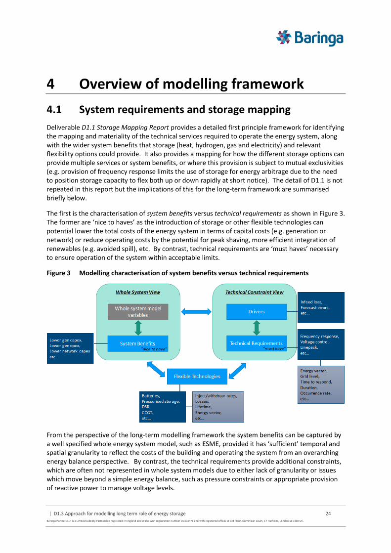
The first is the characterisation of system benefits versus technical requirements as shown in Figure 3. The former are ‘nice to haves’ as the introduction of storage or other flexible technologies can potential lower the total costs of the energy system in terms of capital costs (e.g. generation or network) or reduce operating costs by the potential for peak shaving, more efficient integration of renewables (e.g. avoided spill), etc. By contrast, technical requirements are ‘must haves’ necessary to ensure operation of the system within acceptable limits.
Figure 3 Modelling characterisation of system benefits versus technical requirements
From the perspective of the long-term modelling framework the system benefits can be captured by a well specified whole energy system model, such as ESME, provided it has ‘sufficient’ temporal and spatial granularity to reflect the costs of the building and operating the system from an overarching energy balance perspective. By contrast, the technical requirements provide additional constraints, which are often not represented in whole system models due to either lack of granularity or issues which move beyond a simple energy balance, such as pressure constraints or appropriate provision of reactive power to manage voltage levels.

| D1.3 Approach for modelling long term role of energy storage 25
Baringa Partners LLP is a Limited Liability Partnership registered in England and Wales with registration number OC303471 and with registered offices at 3rd Floor, Dominican Court, 17 Hatfields, London SE1 8DJ UK.
As a result there are two key sets of interactions and associated trade-offs that must be represented:
The interaction between the evolution of the wider energy system and what it means for technical requirements. For example, over time increased levels of storage may help support more efficient integration of wind generation by helping to avoid spill, but increasing levels of wind whose output cannot be forecast perfectly will lead to increase levels of reserve requirements
Flexible technologies (both storage and others such as DSR, CCGT/OCGT, interconnectors) can be used to system benefits and/or technical requirements, but not necessarily all aspects of these simultaneously. Hence the role for storage is a complex function of where it can provide the most value against the competing set of alternatives
The final set of system requirements and system benefits that it is proposed to cover is outlined in D1.1 and summarised in Table 3 and

| D1.3 Approach for modelling long term role of energy storage 26
Baringa Partners LLP is a Limited Liability Partnership registered in England and Wales with registration number OC303471 and with registered offices at 3rd Floor, Dominican Court, 17 Hatfields, London SE1 8DJ UK.
Table 4 .
Table 3 Summary of system benefits
Vector Application
Location in network (Building,
Distribution, Transmission)
Timescale Avoided
generation capex
Avoided generation
opex
Avoided network
capex
Multiple Seasonal storage B / D / T Months
Multiple Network congestion relief
D / T hours
Multiple Network infrastructure investment deferral
D / T hours-days
Multiple Demand shifting and peak reduction
B / D / T hours-days
Multiple Variable supply resource integration
B / D / T hours-days
Heat Flexible waste heat utilisation
B / D / T hours-days
| D1.3 Approach for modelling long term role of energy storage 27
Baringa Partners LLP is a Limited Liability Partnership registered in England and Wales with registration number OC303471 and with registered offices at 3rd Floor, Dominican Court, 17 Hatfields, London SE1 8DJ UK.
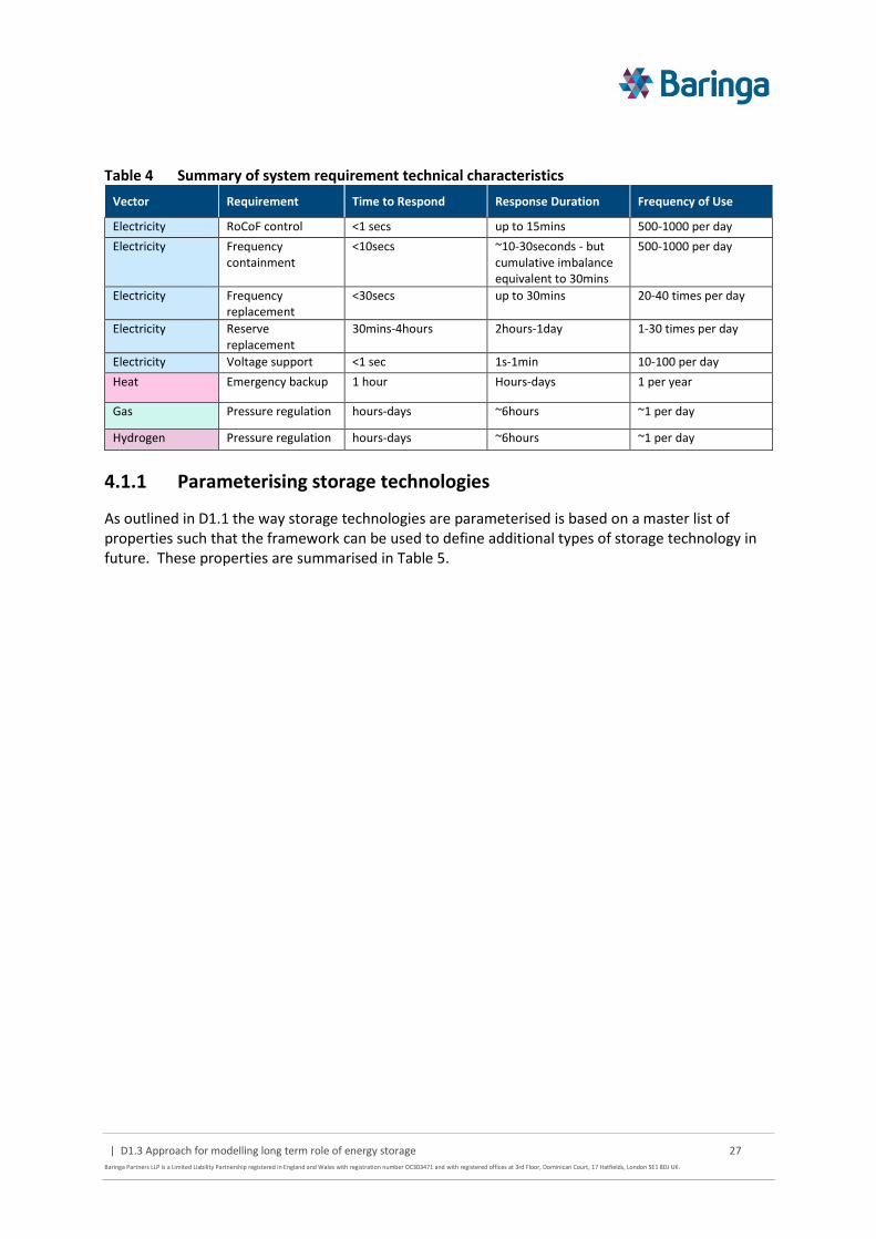
Table 4 Summary of system requirement technical characteristics
Vector Requirement Time to Respond Response Duration Frequency of Use
Electricity RoCoF control <1 secs up to 15mins 500-1000 per day
Electricity Frequency containment
<10secs ~10-30seconds - but cumulative imbalance equivalent to 30mins
500-1000 per day
Electricity Frequency replacement
<30secs up to 30mins 20-40 times per day
Electricity Reserve replacement
30mins-4hours 2hours-1day 1-30 times per day
Electricity Voltage support <1 sec 1s-1min 10-100 per day
Heat Emergency backup 1 hour Hours-days 1 per year
Gas Pressure regulation hours-days ~6hours ~1 per day
Hydrogen Pressure regulation hours-days ~6hours ~1 per day
4.1.1 Parameterising storage technologies
As outlined in D1.1 the way storage technologies are parameterised is based on a master list of properties such that the framework can be used to define additional types of storage technology in future. These properties are summarised in Table 5.

| D1.3 Approach for modelling long term role of energy storage 28
Baringa Partners LLP is a Limited Liability Partnership registered in England and Wales with registration number OC303471 and with registered offices at 3rd Floor, Dominican Court, 17 Hatfields, London SE1 8DJ UK.
Table 5 Generic parameterisation of storage technologies
Parameter Description Primary model use
Input What is the form of input energy from the storage? Determine relevant energy vector (electricity, heat, etc.) and / or siting (e.g. building / grid-level)
Output What is the form of output energy from the storage?
Energy density How much energy can be stored per unit mass (or volume equivalent)
Response Rate How quickly can the storage begin discharging/charging Ability to deliver specific technical requirements Duration How long typically can the storage discharge/charge
(min/max bounds)? Inject/withdraw rate What is the typical charge/discharge rate?
Effective capacity (%) Can the full storage capacity be used or is there a derating to avoid deep discharge?
Drives the effective cost of installation and operation of storage
Round trip efficiency (%) How much energy is available after one charge/discharge cycle?
Temporal losses (%/day) How much energy is lost when stored over time?
Max lifetime (years / cycles) What is typical operating lifetime
CAPEX Estimates of current and future capital costs (where possible differentiated by £/MW and £/MWh
OPEX Estimates of current and future fixed operating costs
Maximum build quantity Is there a maximum volume that may be built in the UK (e.g. due to physical constraints on pumped storage)?
Constrains the amount of storage that can be deployed
Maximum build per year Is there a maximum level of new capacity that can be constructed per year (e.g. due to supply chain constraints?)
In a small number of cases it may be possible to reflect these input parameters indirectly as part of the final data seen by the optimisation model, as opposed to adding more complexity explicitly to the formulation. For example, the effective capacity could be pre-processed to increase the implied unit cost of capacity rather than adding an additional constraint which limited the operational dispatch to x% of this capacity.
Endogenous versus exogenous storage sizing
Storage size is generally parameterised over two main dimensions, the effective discharge rate in power terms and the storage volume in energy terms. The ratio of maximum (resp. minimum) power/energy drives the minimum (resp. maximum) discharge duration. For some storage technologies there is flexibility in the ratio of power/energy that can be provided via different configurations of the same technology with different separate costs for £/MWh (scaling directly with volume – e.g. number of cells) and £/MW (generally set more by the balance of system costs).
ESME currently has the functionality to represent this trade-off endogenously by choosing the ratio as part of the new build investment decision (subject to min/max bounds on the effective duration of storage withdrawal) and it is proposed to retain this representation for this framework. Where it is not possible to source separate £/MWh and £/MW data on costs the storage technology configuration can still be represented by providing only value for effective duration (i.e. fixing the power/volume ratio).

| D1.3 Approach for modelling long term role of energy storage 29
Baringa Partners LLP is a Limited Liability Partnership registered in England and Wales with registration number OC303471 and with registered offices at 3rd Floor, Dominican Court, 17 Hatfields, London SE1 8DJ UK.
Open design questions
For some electricity storage technologies it may be possible to run them for short periods above their rated discharge capacity, but with some degradation in terms of a reduced operating life or available energy density. This type of operation is also possible for some of the competing providers of flexibility, such as existing pumped storage and coal15.
It may be possible to represent such a choice endogenously within the modelling framework – i.e. to explore the economic trade-offs of using the storage technologies in such a way. However, for simplicity (due to the fact this may require an integer or non-linear optimisation formulation which would impact performance) it is proposed that in the first version of the model this issue is explored via the creation of additional storage technologies with adjusted parameters (with e.g. higher output and lower lifetime/energy density) to understand the extent to which the energy system favours such a configuration. If this proves material, endogenous functionality could be added.
4.2 Key sources of modelling complexity
Before outlining the high-level design of the proposed modelling framework it is important to identify the key drivers of complexity (from the review of literature in section 3 and previous experience). The fundamental trade-off revolves around performance of the model (particularly when framed around one or more optimisation techniques) versus the level of detail necessary to generate insights into the role of storage. In addition, the level of detail can significantly impact on the input data requirements.
This complexity manifests itself in four main areas which are described below and referred back to in subsequent sections:
Temporal granularity – both in terms of investment decision making over the pathway to 2050 and in terms of the operation of the system
Spatial granularity – the topological representation of network infrastructure
Co-optimisation of energy vectors – the level of detail in each vector may not need to be ‘equivalent’ to understand the role of storage
Uncertainty – both over the longer term (e.g. fundamental uncertainty over technology cost) or in short term operation (e.g. forecast errors associated with intermittent renewables or demand)
4.2.1 Temporal granularity
The fundamental challenge for temporal granularity is that the key features of interest (covering both technical requirements and system benefits) span the range from seconds to years as shown in Figure 4.
15 http://www2.nationalgrid.com/uk/services/balancing-services/system-security/maximum-generation/

| D1.3 Approach for modelling long term role of energy storage 30
Baringa Partners LLP is a Limited Liability Partnership registered in England and Wales with registration number OC303471 and with registered offices at 3rd Floor, Dominican Court, 17 Hatfields, London SE1 8DJ UK.
Figure 4 Drivers of storage value across different timescales
It is likely to be impractical to simultaneously model both investment and operational decisions across the full spectrum of timescales. Off-model estimates for ESME suggest that significantly reducing the complexity in the wider energy system representation (e.g. collapsing multiple electric vehicle technologies into one) whilst considering 5-yearly time periods and 5 characteristic days within year at hourly resolution would increase the solving time for a single deterministic run from order of minutes to potentially 24 hours. Considering electricity only examples in the literature, the timescales for modelling do not to tend to go below 15-30 minutes and at this level of resolution are focused primarily on operational analysis.
To manage the level of complexity for this project insights from the literature review highlight:
The need to decompose separate Short-Term (ST) operational analysis from Long-Term (LT) investment analysis rather than trying to co-optimise both simultaneously. There are a number of examples where the ST and LT ‘modules’ are coupled together so that they are running iteratively with information from one informing the solution for the other and vice versa
For the electricity system, which tends to have the shortest timescale requirements, a resolution of 1-hour seems appropriate for capturing the key dynamics of system operation for storage, with very short timescale requirements captured in the form of simultaneous “holding volumes”. I.e. choosing to reserve a mix of installed technology capacity to meet these requirements in a given hour, which then limits or removes their ability to operate as part of the wider energy balancing actions within the energy system
The use of characteristic periods to understand the variation in system conditions across the year rather than modelling a full 8,760 hours. These need to reflect fundamental differences in system conditions such as heat demand in winter versus other seasons or across the weekday/weekend. For storage operation, the length of the period may also need to be in the range of ~1 week to understand the true extent of cycling and reduce the potential for start/end effects (e.g. having to specify a volume in storage at the start
“VST” “ST” “MT” “LT”
secs mins hours days weeks seasonal
RoCoF control
Voltage control
Frequency containment
Frequency replacement
Reserve Replacement
Network constraints
Peak load shifting
Variable supply integration
Seasonal storage
Network constraints
Peak load shifting
Variable supply integration
Seasonal storage
Network constraints
Peak load shifting
Variable supply integration
Seasonal storage
Pressure regulation
Emergency backup
Pressure regulation
Electricity
Heat
Gas / H2
Operating margins
years decades
Generation capacity
Transmission capacity
Storage capacity
Demand interventions
Generation capacity
Transmission capacity
Storage capacity
Demand interventions
Generation capacity
Transmission capacity
Storage capacity
Demand interventions

| D1.3 Approach for modelling long term role of energy storage 31
Baringa Partners LLP is a Limited Liability Partnership registered in England and Wales with registration number OC303471 and with registered offices at 3rd Floor, Dominican Court, 17 Hatfields, London SE1 8DJ UK.
of the period). However, rather than modelling a full 168 hours it may be possible to exploit periodicity in the periods (e.g. if weekdays look similar and weekends look similar) to collapse the number of hours that need to be modelled to reflect a full week16.
4.2.2 Spatial granularity
Spatial granularity for network infrastructure is driven by two main dimensions
The number of grid levels – for example, NTS (National Transmission System) versus LDN (Local Distribution Network) at a high level or even within level, separating LDNs into different voltage levels17 for electricity or pressure levels for gas
The number of geographical regions or nodes describing the flows of energy across and between the different network levels
Examples from the literature illustrate the challenge of maintaining detailed levels of granularity at both NTS and LDN level simultaneously and tend to focus the detail on one or the other, particularly when representing multiple energy vectors. In a multi-vector model the complexity arises because gas/H2 issues are focused predominantly at the NTS-level, whereas for electricity they span both NTS and LDN, with greater potential investment (and scope for savings at LDN level).
Although this project is focused on the role of storage as opposed to a detailed representation of energy networks it is important to represent them in sufficient detail to the extent that storage can provide a system benefit (e.g. reduce network investment, avoid curtailment of renewables behind a network constraint) or a technical requirement (e.g. gas/H2 pressure regulation). Figure 5 outlines a range of potential options for varying spatial complexity.
Figure 5 Options for varying spatial complexity
16 E.g. See Samsatli S and Samsatli N, A general spatio-temporal model of energy systems with a detailed account of transport and storage, Computers and Chemical Engineering 80 (2015) 155–176 17 E.g. EHV (Extra-High Voltage), HV (High Voltage) and LV Low Voltage
Z2Z1
Z2
Z3 Z4
Z6Z5
Z1
• Single node system
• No network constraints
• No local variation in services or demand/supply balance
• No separation of transmission and distribution
• Multi-node transmission system, simple distribution
• Transmission constraints
• Local variation in services or demand/supply balance
• Single aggregated distribution network per zone
• BSP constraints for each aggregated distribution zone
• Multi-node transmission and distribution system
• Transmission constraints
• BSP constraints
• Local variation in services or demand/supply balance, separated by grid level
• Will need archetypal LDNs, infeasible to collect data for actual LDNs
Z1
• Single-node transmission and multi-node distribution system
• No transmission constraints
• BSP constraints for archetypal distribution networks
Z1
Distribution level complexity
Tra
nsm
issi
on
leve
l co
mp
lexi
ty

| D1.3 Approach for modelling long term role of energy storage 32
Baringa Partners LLP is a Limited Liability Partnership registered in England and Wales with registration number OC303471 and with registered offices at 3rd Floor, Dominican Court, 17 Hatfields, London SE1 8DJ UK.
Note: BSP = Bulk Supply Point where energy flows interact between the LDN and NTS level.
Various decomposition techniques are flagged in the literature for reducing spatial complexity, analogous to the ST-LT coupling for managing temporal granularity. In the same example16, the spatial investment/operating decisions for conversion and storage infrastructure are also decomposed from those of the transport network infrastructure and then coupled via iteration between models. The challenge in this particular example is that it leads to three separately coupled models (trying to manage both spatial and temporal granularity) which have to be iterated sequentially to find an equilibrium position.
It is important to note that all examples in the literature which consider LDN level issues and try to scale them to the national level make use of archetypal networks, constructed in a number of different ways (see section 3.5).
Detailed network operational analysis
In addition to the granularity in the spatial representation itself (e.g. the number of spatial nodes / zones) the method of operational analysis is also a key driver of complexity. From the literature review in section 3 many of the system studies use a simple energy supply/demand balance for the underlying representation of the operation of the energy system and network, as this facilitates high levels of temporal granularity and/or coupling with capacity expansion analysis.
When focused on one particular energy vector, such as electricity, some studies also use more detailed power flow analysis to better understand a number of network constraints and system operational issues such as dynamic transmission losses and reactive power, given a fixed configuration of the network. This enables a more accurate understanding of:
Constraints on different networks (e.g. voltage, thermal, pressure limits) that may trigger a need for additional network reinforcement
Operating costs and how they can be minimised (e.g. minimising active power losses or managing compressor use on a gas network)
For electricity the most accurate approach is a full AC power flow representation, but this is a highly computationally intensive, non-linear problem solved by iterative techniques such as the Newton-Raphson method18. A DC power flow (linearly optimisable) approximation is possible, but only considers active power flows, assumes perfect voltage support and reactive power management, and neglects dynamic transmission losses19. The situation is analogous with respect to heat and gas, e.g. in terms of a complex non-linear representation of flows and pressure loss alongside potential linear simplifications20.
It is less tractable to co-solve a multi-vector representation simultaneously using separate, iterative non-linear techniques. Each vector must be solved individually (via the iterative method) and coupled to the other vectors to determine an appropriate equilibrium position (see literature examples in section 3.2). This makes it difficult to explore multiple variants of system conditions (e.g. loads) and/or system configurations (e.g. different network capacities). Even where linear
18 http://www.openelectrical.org/wiki/index.php?title=Newton-Raphson_Power_Flow 19 KU LEUVEN (2014) DC power flow in unit commitment models 20 C Correa-Posada, P Sanchez-Martin (2014) Gas Network Optimization: A comparison of Piecewise Linear Models - Preprint submitted to Chemical Engineering Science June 22, 2014

| D1.3 Approach for modelling long term role of energy storage 33
Baringa Partners LLP is a Limited Liability Partnership registered in England and Wales with registration number OC303471 and with registered offices at 3rd Floor, Dominican Court, 17 Hatfields, London SE1 8DJ UK.
approximations can enable co-optimisation they can still add significantly to the complexity of the problem compared to an energy balance representation. In addition, this introduces another degree of decomposition and coupling within the operational analysis itself, beyond any coupling necessary to link short term operational and long-term investment analysis.
The value that more detailed dynamic or steady-state network analysis can add is also dependent on the level of spatial detail being represented in the underlying topology. For example, where this shifts from a detailed nodal representation to a more aggregated zonal boundary, the value diminishes due to the other simplifications that are introduced.
For the purposes of understanding the role of storage (in a multi-vector, multi-location manner) temporal granularity appears to be the single most important dimension from the review of literature, coupled with the ability to reflect a range of uncertainty within key temporally dependent factors, such as intermittent renewable output or demand variation. As a result, the need to explore multiple sets of system conditions and network capacities with high temporal granularity is likely to require a simpler energy balance approach, even if this is a more approximate representation of network operation.
Minimisation of operating costs tends to be of second order importance compared to new network investment and can potentially be proxied indirectly, by supplementary constraints where an energy balance approach does not reflect this explicitly (e.g. injection or absorption of reactive power to maintain voltage levels).
Network capacity expansion costs are more important than network operating costs. However, these are again likely to be significantly smaller in absolute terms compared to the costs of energy supply. However, it is possible to undertake repeated “off-model” operational analysis to construct parameterised reinforcement cost curves that can then be used within an energy balance representation. Whilst this is still only a proxy for the operational analysis it helps to better reflect underlying network constraints. This is the approach used for electricity and heat networks within the EPN model whereby the impact of thermal/voltage and pressure/velocity operating constraints are run under multiple network configurations and loads to construct a parameterised reinforcement curve.
It should be noted that starting with an energy balance representation does not preclude the introduction of more detailed forms of operational analysis in future.
4.2.3 Co-optimisation of energy vectors
When considering the operation of the energy system it is important to understand the extent to which an operational decision in one point of the system materially impacts another part of the system, potentially across different energy vectors, with respect to the role of storage. Where this is not the case the less relevant part of the system can be modelled in less detail or potentially not considered at all.
From the review of literature and previous experience it is clear that electricity is the most complicated of the energy vectors to model (in particular given temporal and spatial granularity issues) and many of the other energy vectors interact directly or indirectly to deliver benefits or provide technical requirements for the electricity system.

| D1.3 Approach for modelling long term role of energy storage 34
Baringa Partners LLP is a Limited Liability Partnership registered in England and Wales with registration number OC303471 and with registered offices at 3rd Floor, Dominican Court, 17 Hatfields, London SE1 8DJ UK.
Figure 6 Stylised example of interactions between vectors
Figure 6 provides an illustration of some, but not all of the interactions across the different vectors:
The potential use of building heat storage to shift electric load and impact electricity system benefits and requirements (and competing options such as grid-scale battery storage) is significant and hence requires a strongly linked representation
By contrast the role of storage for District Heat Networks (DHN) is indirect. DHNs are typically designed with large thermal stores as an integrated part of the design to provide backup capability and help with sizing of the heat supply source. Where the heat supply source is CHP (Combined Heat and Power) the benefit is indirect in terms of flexibility in the operation of the plant to provide electricity system benefits and requirements (which if significant could be a potential driver for oversizing). It is not therefore necessary to model the complex operation of the heat network (and associated temperature and pressure requirements) simultaneously with the rest of the energy system, provided that a reasonable approximation of the flexibility that CHP would have can be established
In a similar manner, the primary operational link between the NTS gas network and the wider energy system is the indirect flexibility provided by linepack (and influenced by geographical locations of gas storage and available supply sources) which may limit the flexibility with which variable gas electricity generation may be run. As per DHN if an appropriate proxy for this flexibility (accounting for variation in supply/demand across a set of high-level NTS level nodes) can be established it may be not be necessary run a detailed simulation of the gas network operation simultaneously with the wider energy system

| D1.3 Approach for modelling long term role of energy storage 35
Baringa Partners LLP is a Limited Liability Partnership registered in England and Wales with registration number OC303471 and with registered offices at 3rd Floor, Dominican Court, 17 Hatfields, London SE1 8DJ UK.
4.2.4 Uncertainty
From the literature review uncertainty is a key driver of the value of storage and other flexible assets. Uncertainty can arise in two key areas:
Long-Term (LT) projections focused around technology costs or technical characteristics (e.g. what will the cost of different battery technologies be in 2050) or fundamental shifts in underlying energy service demands (e.g. due to population or GDP growth)
LT sources of uncertainty are more straightforward in the sense of addressing them within a modelling framework and we propose to leverage the existing combination of scenarios and Monte Carlo simulated inputs that form the core of ESME’s approach to uncertainty analysis.
Short-Term (ST) uncertainty is comprised of two key, interlinked elements:
General variation in day-to-day parameters that effect the optimal ST operation of the system such as demand patterns, intermittent wind output, interconnector flows etc.
Forecast errors (particularly within day or day-ahead) related to the expected variation in demand, output from intermittent generation or tripping of thermal plant that can lead to adjustments in operation of the system ahead of time.
ST uncertainty is potentially more complicated in terms of the spectrum of possible approaches given the compounding effect of forecast errors on top of general variation. This uncertainty manifests itself in the continuing attempts of an SO (System Operator) to position generation (or DSR) to cover unexpected events, as the electricity system has to be balanced in near real-time.
This is subject to the dynamic technical constraints of the different plant types (e.g. how quickly the plant can respond or how long it must remain off before restarting). In some cases it may be more cost-effective for the system as a whole to bring on slower ramping thermal plant earlier in the day rather than relying on more responsive, but more expensive peaking plant, in anticipation of low wind generation and high demand. However, if the forecast is wrong and wind is much higher and demand lower than expected the costs (and associated emissions) of positioning this plant unnecessarily may be more expensive than simply having used the available plant on the system if the SO had not acted.
Storage is particularly valuable in this context given its fast response times. In addition, the nature of the opportunity cost of (in)action can look considerably different (potentially more or less expensive compared to other flexibility options) due to the cost differentials from injecting/withdrawing in discontinuous time periods.
A number of options are available to address uncertainty in terms of both general variation and forecast are described below. The techniques can in many cases be combined to better address both elements of uncertainty, but at the expense of model performance.

| D1.3 Approach for modelling long term role of energy storage 36
Baringa Partners LLP is a Limited Liability Partnership registered in England and Wales with registration number OC303471 and with registered offices at 3rd Floor, Dominican Court, 17 Hatfields, London SE1 8DJ UK.
Figure 7 Techniques to address ST uncertainty
Reserve holding constraints
In addition to the standard perfect foresight deterministic dispatch of plant to meet the required supply/demand energy balance, the reserve holding constraints run in parallel across the day, potentially varying in size based on other system parameters, and effectively limit (or remove) the ability of plant to contribute to the energy balance.
For example, this may cover the potential swings in forecast error in demand or wind, or the probability of a plant tripping (typically the largest ‘infeed loss’). The optimisation works out the least cost-way of positioning and holding plant to cover the overarching reserve requirement whilst still meeting the energy balance constraint – e.g. maintaining thermal plant at their min stable level of generation such that they could ramp quickly if needed. The only contribution to the energy balance is this minimum stable generation and the headroom above this is the ‘reserve volume’.
Interleaving and myopic foresight
Interleaving tries to proxy a rolling series of dispatch decisions which are made based on the best available information at a point in time t (i.e. myopic rather than perfect foresight), but which turns out to be wrong once a point t+1 is reached, for example a forecast of demand or wind output compared to the outturn (this is illustrated in Figure 8). As a result, the decisions made during t (in the absence of perfect future information) may mean that plants operating at the start of time period t+1 are different compared to a situation where the operator had perfect foresight of t and
Ability to reflect general system variation
Ab
ility
to
ref
lect
fo
reca
st e
rro
rs
Deterministic + reserve holding constraints
Perfect foresight single deterministic
Deterministic + reserve holding + interleaving
Stochastic optimisation
+ Monte Carlo
+ Monte Carlo
+ Monte Carlo
Low
Medium
High
Very high
Complexity

| D1.3 Approach for modelling long term role of energy storage 37
Baringa Partners LLP is a Limited Liability Partnership registered in England and Wales with registration number OC303471 and with registered offices at 3rd Floor, Dominican Court, 17 Hatfields, London SE1 8DJ UK.
t+1, which subsequently affects the dispatch in t+1. For example, if the lowest cost plant was switched off and incapable of ramping in the time available in t+1 alone it would not be option.
Figure 8 Illustration of interleaving process
Interleaving can be combined with the reserve holding constraints, but that subtly changes what the forecast errors represent. In the combined case the forecast error represented by the reserve constraints would primarily be used to reflect uncertainty below the hourly resolution of the energy balancing and the interleaving would focus on forecast errors x-hours prior to this. If only the reserve constraints are used the forecast errors would effectively represent a proxy for both sub-hourly and x-hours ahead.
The use of interleaving is preferred because it provides a better representation of the acts of both holding and subsequently utilising reserve, whereas the holding constraint is focused principally on the former. The downside is that the interleaving significantly increases the number of simulated periods that need to be run, which increases as the size of the interleaved overlap decreases.
Monte Carlo
This is the underlying approach used in ESME (to simulate LT uncertainty) whereby multiple sets of (potentially correlated) inputs are simulated and the deterministic model is run multiple times for each set of inputs to build up a distribution of outputs, as illustrated in Figure 9.
In the ST this can be used to reflect uncertainty in the variation of general system parameters such as demand, wind, etc. However each individual simulation is still undertaken within the paradigm of a deterministic model. As a result the Monte Carlo treatment of uncertainty can be layered on top of both the simple reserve holding case and/or the case with interleaving. Whilst the use of Monte Carlo simulation can significantly improve the understanding of how wider system variation may affect storage the complexity scales linearly with the number of simulations that are required.
Stage 1
Stage 2
Stage 3
Interleaving
t t+1 t+2

| D1.3 Approach for modelling long term role of energy storage 38
Baringa Partners LLP is a Limited Liability Partnership registered in England and Wales with registration number OC303471 and with registered offices at 3rd Floor, Dominican Court, 17 Hatfields, London SE1 8DJ UK.
Figure 9 Illustration of Monte Carlo
Stochastic optimisation
Stochastic optimisation effectively combines the treatment of both forecast error and wider system uncertainty (e.g. an uncertain expectation of whether demand will be high/medium/low) into a single optimisation problem. The solution reflects an optimal ‘hedging’ dispatch – i.e. that it attempts to minimise the expected system costs in the face of future uncertainty whilst still being feasible across the possible set of outturn conditions. The fundamental challenge with stochastic optimisation is that the problem size can rapidly become intractable.
Figure 10 Illustration of stochastic optimisation
Variations are possible to try and capture some of the benefits of the stochastic approach whilst retaining tractability. For example, applying the stochastic optimisation on a rolling (i.e. partially interleaved) basis across the time period, but with a shorter horizon for each rolling section within the time period.
Robust optimisation is another alternative approach to dealing with uncertainty, which is more tractable than stochastic optimisation. As mentioned in section 3.6, robustness is implied to mean the best solution against the worst possible data realization (e.g. what is the least cost investment necessary to maintain a security of supply standard at ≥ a defined value where there is uncertainty over the ability of different plant to contribute to the standard). This is particularly appropriate where feasibility is the primary concern, as infeasibility is assumed to lead to far greater cost or some unquantifiable hazard. However, for the purposes of this study it is less appropriate as we are primarily trying to understand the economic value to the system of storage versus competing flexibility options, driven in large part by ‘nice to have’ system benefits as opposed to purely technical system requirements.
4.3 High-level design
An overview of the high-level conceptual design for the modelling framework is shown in Figure 11, based on the understanding of the design requirements and insights from the literature. The key features proposed are:
Single Deterministic Run
Multiple solutions
Repeat times X
Multiple inputs
Stochastic optimisation (x1)

| D1.3 Approach for modelling long term role of energy storage 39
Baringa Partners LLP is a Limited Liability Partnership registered in England and Wales with registration number OC303471 and with registered offices at 3rd Floor, Dominican Court, 17 Hatfields, London SE1 8DJ UK.
An explicit separation of LT planning and investment decisions (over the pathway to 2050) from ST operational analysis due to likely computational challenges. The Long-Term Module (LTM) would still have a coarse level of resolution for basic operational analysis to cover e.g. inter seasonal storage, whereas the Short-Term Module (STM) would have a more granular (hourly) resolution over characteristic periods (most likely weeks)
For the LTM it is proposed to keep the same spatial resolution as ESME (i.e. political UK regions) for the NTS-level representation. Whilst this does not always align directly with key parts of the underlying electricity and gas infrastructure it is considered beyond the scope of this project to adjust the base service demand/existing capacity data. However, this could be revised in future without significantly altering the proposed LTM structure (the NTS structure in the STM automatically mirrors that in the LTM). At distribution level it is proposed to create a flexible data structure that allows the creation of simple parameterised archetypal electricity LDNs within each NTS node (and potentially with multiple sub-voltage levels). However, the level of final detail will be driven to a large extent by acceptable model performance requirements.
The STM and LTM would be tightly coupled with iteration between the two modules until a defined convergence point is reached (e.g. no further tangible change in investment decisions given the current STM results)
The STM would co-optimise the supply/demand balance and wider system requirements across the multiple energy system vectors simultaneously to minimise the cost of system operation in each characteristic period given the available capacity options from the LTM
The LTM would co-optimise the investment (and coarse supply/demand operation) in new technologies and storage to ensure that future energy service demands and other constraints are met at lowest cost over the pathway
A separate electricity Network Input Module (NIM) would contain a series of parameterised LDN network reinforcement functions for use in the LTM module that are driven from the energy supply/demand balance. Given the principle focus on storage investment and operation across multiple vectors this approximation decouples the need for e.g. computationally intensive electricity optimum power flow analysis to be considered directly in the STM and simplifies this to a (granular) representation of energy balancing across multiple vectors. A number of options to create these functions have been outlined in section 5.4 including:
Using the ETI’s Macro Electricity Distribution Tool (MEDT), which was also used in the recent Consumer Vehicles and Energy Integration (CVEI) project. This is currently our preferred option.
Using the ENA/Ofgem Transform model (discussed in section 3.5) if it is possible to obtain a licence for this21
Defining illustrative LDN topologies and undertaking steady-state power flow analysis (considering thermal and voltage limits) upon a number of test configurations in a similar manner to that for EPN (using Sincal).
21 We have contacted WPD and EA Technology (the original project lead) and are in the process of contacting ENA regarding the ability to use or licence this tool

| D1.3 Approach for modelling long term role of energy storage 40
Baringa Partners LLP is a Limited Liability Partnership registered in England and Wales with registration number OC303471 and with registered offices at 3rd Floor, Dominican Court, 17 Hatfields, London SE1 8DJ UK.
A more detailed description of each module and the process of coupling the STM and LTM is provided in section 5.
Figure 11 Overview of high-level conceptual design
Based on the review of existing modelling approaches in section 3 Figure 12 illustrates, in a fairly stylised manner, where the proposed framework would sit in the existing modelling landscape; focusing on integrated frameworks rather than loosely coupled ‘patchworks’ of tools. At a high-level, the framework is similar to that in the Imperial WeSim model, but with the intention to extend this from an electricity-focus to consider multiple energy vectors. This is likely to require some rebalancing of the level of temporal/spatial granularity seen in this model to be able to explore multiple vectors whilst retaining the ability to explore uncertainty in a systematic manner.
Figure 12 “Stylised” positioning of proposed framework in current modelling landscape

| D1.3 Approach for modelling long term role of energy storage 41
Baringa Partners LLP is a Limited Liability Partnership registered in England and Wales with registration number OC303471 and with registered offices at 3rd Floor, Dominican Court, 17 Hatfields, London SE1 8DJ UK.
5 Modules
5.1 Long-Term Module (LTM)
The proposed LTM requirements are very similar to the ESME model; providing a least-cost optimisation pathway to 2050, whereby decisions are taken around where and when to deploy new technologies and how to operate these, albeit with a limited within year granularity. It is proposed to use the latest ESME v4.1 framework and dataset as the starting point for the LTM, keeping much of the core formation:
Objective function: minimise total discounted energy system costs over the pathway
Decision variables: conversion/network/storage capacity build, activity and resource use
Constraints: supply/demand balancing, carbon, peak reserve margin, maximum technology build rate/quantity, maximum resource availability, etc.
Temporal resolution: it is proposed to keep the ability to reflect 5 or 10-year time periods and the same broad level of within year time slicing to cover the MT/LT areas of temporal granularity outlined in Figure 4, along with a less granular short-term representation (i.e. fewer diurnal time slices), which is subsequently informed by the STM results
Uncertainty: retain the option for Monte Carlo analysis of key long-term drivers. However, as discussed in sections 5.3 and 7 LTM run-times (including iteration with the STM) may mean that key LT uncertainties (e.g. storage costs and level of electricity interconnector capacity) are explored through discrete sensitivities.
This section focuses on the key additions or updates necessary to meet this project’s requirements.
Energy system representation
ESME does not currently contain an explicit representation of the gas network and it is proposed to add an NTS (and single-step LDN) level representation and associated storage options to reflect the related system requirements around gas pressure regulation and the potential impact on electricity system flexibility (and similarly for hydrogen). Resource and availability constraints at entry points into the (due to interconnectors or LNG facilities) will be need to be treated via scenarios rather than endogenous decisions, as they lie at the boundary of the model
Additional conversion technologies to ensure relevant interactions across the system are represented (e.g. power-to-gas)
Potential simplification of non-core technologies – given the expansion of detail in some part of the LTM it may be necessary to simplify areas of the ESME representation to improve run-times (e.g. collapsing multiple electric vehicle variants).
System technical requirements
The additional technical requirements outlined in 4.1 must be represented in both the STM in detail and in the LTM in a simpler form. The latter will likely take the form of a set of flexibility constraints, analogous to but replacing the existing flexibility margin constraint. In some cases the scale of the requirement may be an
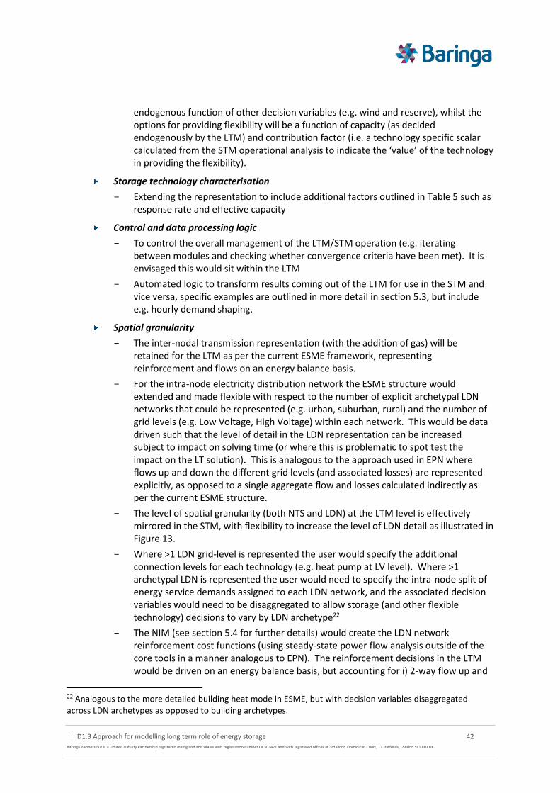
| D1.3 Approach for modelling long term role of energy storage 42
Baringa Partners LLP is a Limited Liability Partnership registered in England and Wales with registration number OC303471 and with registered offices at 3rd Floor, Dominican Court, 17 Hatfields, London SE1 8DJ UK.
endogenous function of other decision variables (e.g. wind and reserve), whilst the options for providing flexibility will be a function of capacity (as decided endogenously by the LTM) and contribution factor (i.e. a technology specific scalar calculated from the STM operational analysis to indicate the ‘value’ of the technology in providing the flexibility).
Storage technology characterisation
Extending the representation to include additional factors outlined in Table 5 such as response rate and effective capacity
Control and data processing logic
To control the overall management of the LTM/STM operation (e.g. iterating between modules and checking whether convergence criteria have been met). It is envisaged this would sit within the LTM
Automated logic to transform results coming out of the LTM for use in the STM and vice versa, specific examples are outlined in more detail in section 5.3, but include e.g. hourly demand shaping.
Spatial granularity
The inter-nodal transmission representation (with the addition of gas) will be retained for the LTM as per the current ESME framework, representing reinforcement and flows on an energy balance basis.
For the intra-node electricity distribution network the ESME structure would extended and made flexible with respect to the number of explicit archetypal LDN networks that could be represented (e.g. urban, suburban, rural) and the number of grid levels (e.g. Low Voltage, High Voltage) within each network. This would be data driven such that the level of detail in the LDN representation can be increased subject to impact on solving time (or where this is problematic to spot test the impact on the LT solution). This is analogous to the approach used in EPN where flows up and down the different grid levels (and associated losses) are represented explicitly, as opposed to a single aggregate flow and losses calculated indirectly as per the current ESME structure.
The level of spatial granularity (both NTS and LDN) at the LTM level is effectively mirrored in the STM, with flexibility to increase the level of LDN detail as illustrated in Figure 13.
Where >1 LDN grid-level is represented the user would specify the additional connection levels for each technology (e.g. heat pump at LV level). Where >1 archetypal LDN is represented the user would need to specify the intra-node split of energy service demands assigned to each LDN network, and the associated decision variables would need to be disaggregated to allow storage (and other flexible technology) decisions to vary by LDN archetype22
The NIM (see section 5.4 for further details) would create the LDN network reinforcement cost functions (using steady-state power flow analysis outside of the core tools in a manner analogous to EPN). The reinforcement decisions in the LTM would be driven on an energy balance basis, but accounting for i) 2-way flow up and
22 Analogous to the more detailed building heat mode in ESME, but with decision variables disaggregated across LDN archetypes as opposed to building archetypes.

| D1.3 Approach for modelling long term role of energy storage 43
Baringa Partners LLP is a Limited Liability Partnership registered in England and Wales with registration number OC303471 and with registered offices at 3rd Floor, Dominican Court, 17 Hatfields, London SE1 8DJ UK.
down the LDN (as network ratings are not necessarily symmetric) and ii) supply / net demand drivers to account for potential distinctions in reinforcement for thermal limits versus voltage issues with large amounts of distributed generation.
Figure 13 Data driven flexibility to increase LDN granularity for both LTM/STM
5.1.1 LTM boundary
The system modelled reflects the UK only to retain consistency with the UK’s climate targets. As such, any electricity or gas interconnector/LNG capacity or access to resource constraint commodities (e.g. international biomass markets) can only be reflected by boundary assumptions and e.g. endogenous new build of interconnectors cannot be embedded meaningfully within the framework.
However, as discussed in section 5.2 the boundary for the STM is focused on GB-only (excluding Northern Ireland) as including this would effectively require modelling of Ireland given the Single Electricity Market. Given the relatively small contribution in emissions to the UK total23 it is a reasonable approximation to let decisions for this zone be resolved by the LTM only.
5.1.2 Out of scope
ESME’s spatial representation reflects the England and Devolved Administration political regions24, but this does not necessarily align to the underlying NTS-level infrastructure topology upon which reinforcement decisions are made. Reviewing this representation and re-processing the underlying data (e.g. energy service demands, existing technology capacities and resource availabilities) is considered to be beyond the scope of this project. It may, however, be relevant to align the use of this framework with the potential further requirements of the separate ESD Multi-Vector Network study. This is primarily an exercise in re-cutting the underlying dataset as the LTM framework would provide flexibility to represent a different set of interconnected NTS nodes.
23 ~4% in 2013 from Committee on Climate Change estimates 24 https://en.wikipedia.org/wiki/Regions_of_England
Z2Z1
Multiple LDNs (and BSPs) per Transmission zone
Z2
Z3 Z4
Z6Z5
Z1
Aggregate archetypal LDNs at each transmission zone to have 1 representative LDN connected to each transmission zone

| D1.3 Approach for modelling long term role of energy storage 44
Baringa Partners LLP is a Limited Liability Partnership registered in England and Wales with registration number OC303471 and with registered offices at 3rd Floor, Dominican Court, 17 Hatfields, London SE1 8DJ UK.
Figure 14 Illustration of electricity (left) and gas (right) NTS topology
Source: National Grid
5.2 Short-Term Module (STM)
The core purpose of the STM is to model the operational dispatch of the defined LTM system at a much higher level of temporal granularity to better understand the role of storage against other competing sources of flexibility. This considers co-optimisation across
Multiple energy vectors and grid levels simultaneously as shown previously in Figure 6
Multiple NTS nodes and potential LDN archetypes as shown in Figure 14, mirroring the spatial granularity in the LTM
A given LTM pathway solution is decomposed into a number of separate ST characteristic periods for which the more detailed operation can be solved independently (e.g. 2025 winter week, 2040 summer week) and potentially in parallel. The relevant results are then aggregated up as required (e.g. weeks within the year to an annual level) before being passed back to the LTM.
The basic structure of the STM formulation is:
Objective function: minimise total operating costs over the characteristic period
Decision variables (varying by node and time slice):

| D1.3 Approach for modelling long term role of energy storage 45
Baringa Partners LLP is a Limited Liability Partnership registered in England and Wales with registration number OC303471 and with registered offices at 3rd Floor, Dominican Court, 17 Hatfields, London SE1 8DJ UK.
On/off unit commitment of relevant electricity plant (which e.g. have high fixed start-up or no-load costs)
Technology activity (electricity, DSR shedding or shifting, etc.)
Storage injection and withdrawal
Spill energy volumes
Unserved energy volume (at a high price25 to ensure the operation of the system is both feasible and as part of providing a signal back to the LTM for the value of additional investment26)
Constraints (varying by node and time slice):
Energy supply equals demand (accounting for unserved energy and losses) within node and at different grid levels accounting for flows between grid levels and NTS nodes
Capacity-related constraints (generation, storage, network, interconnectors, DSR load shedding) – e.g. maximum technology activity or storage net injection must be ≤ active capacity, or active storage volume, respectively
Additional dynamic electricity constraints (e.g. min on/off times, min stable generation, max ramp up/down rates)
DSR load shifting constraints – where this source of flexibility is not modelled explicitly in the STM (e.g. building heat storage) it will be modelled as a demand requirement that must be met within a given window of flexibility (e.g. this potentially applies to electric vehicle charging)
Individual constraints for each of the system technical requirements outlined in 4.1 such as frequency control and voltage, or gas pressure regulation. It should be noted that some technical requirements are effectively system-wide (such as frequency containment) and the constraints would be formulated as such as. The approach to structuring these is discussed further in the next section
Within each geographical node it is expected that most technologies with similar characteristics (e.g. building heat storage of the same vintage) would be treated as a single unit for operating purposes in the STM optimisation - i.e. linearising the decision making (and similarly in the LTM for investment, as per ESME). This is essential for performance tractability and similar approaches are used in the other models reviewed as part of the literature. Given the focus on system level flexibility, rather than individual asset performance, loss of detail is only really an issue if further disaggregation of the single unit into multiple units would result in significantly different decision making at the system level. Where this is an issue parameterisation of multiple units would be more important.
5.2.1 Co-optimisation of technical requirements and energy balancing
Most system benefits and services can be captured using a granularity of around 1 hour coupled with operation over a characteristic week to allow for sufficient time to observe storage cycling patterns due to e.g. intermittent renewables variation and weekday/weekend differences. Some system requirements occur at Very Short Term (VST) timescales of seconds to minutes. However, they are relatively few and confined to electricity as illustrated. As modelling at this resolution hugely
25 E.g. current Value of Lost Load in the GB balancing mechanism is priced at £10,000/MWh 26 Supply, demand-side efficiency or response, or fuel switching to non-electric technologies

| D1.3 Approach for modelling long term role of energy storage 46
Baringa Partners LLP is a Limited Liability Partnership registered in England and Wales with registration number OC303471 and with registered offices at 3rd Floor, Dominican Court, 17 Hatfields, London SE1 8DJ UK.
increases the complexity of the problem it is proposed to apply energy balancing at a 1-hourly resolution.
Figure 15 STM temporal granularity
For the technical requirements which require actions within the sub-hour timeframe it is proposed to apply a series of simultaneous reserve holding constraints, to capture how these requirements are met alongside the system energy balance requirement in a manner analogous to how the TSO manages the system.
These constraints capture a volume requirement (e.g. frequency containment) which may vary dynamically as a function of other parameters within the modelled STM energy balance (e.g. wind output). This volume can be met by the available set of ‘flexibility’ options, which are technically capable of providing the service, as built by the LTM and covering both storage and competing alternatives.
Importantly, the choice to use a particular flexibility option must consider that:
As a result of providing a holding volume it cannot contribute to the broader energy balance within the hour (or at least contribute further, e.g. where the holding volume requires a move to generate at a minimum stable level of generation this minimum level would still be provide energy to the balance) to provide wider system benefits (as per the distinction outlined in Figure 3)
secs mins hours days weeks
RoCoF control
Voltage control
Frequency containment
Frequency replacement
Reserve Replacement
Black Start
Network constraints
Peak load shifting
Variable supply integration
Network constraints
Peak load shifting
Variable supply integration
Network constraints
Peak load shifting
Variable supply integration
Pressure regulation
Emergency backup
Pressure regulation
Electricity
Heat
Gas / H2
Operating margins
“VST” “ST”
• Very Short Term (VST) operation requires high granularity, hugely increasing complexity of problem

| D1.3 Approach for modelling long term role of energy storage 47
Baringa Partners LLP is a Limited Liability Partnership registered in England and Wales with registration number OC303471 and with registered offices at 3rd Floor, Dominican Court, 17 Hatfields, London SE1 8DJ UK.
Positioning the flexibility option to provide the holding volume in period t may require active prior to period t, e.g. ramping to min. stable or ensuring there is sufficient volume in storage to provide either upwards and downwards flexibility. Depending on the nature of the technical requirement specific assumptions are imposed for storage e.g. where requirements sub-hour are generally symmetrical (e.g. minor fluctuations up or down in the case of frequency containment) the volume in storage is unchanged during the hour and the most it can contribute is effectively 50% of its volume
Some requirements are “mutually exclusive” – i.e. a flexibility option can only provide one requirement at a time, although they may be able to provide different services throughout the day, by contrast some services may be provided at the same time (e.g. the various frequency requirements)
The duration of the requirement may vary (i.e. the time for which the volume must be held). Whilst most requirements are for both a response time and a duration of response at <1 hour, some such as reserve replacement (e.g. to cover a large plant tripping) have a response <1 hour but a duration of 2+ hours
The generic approach is outlined in Figure 16, reflecting the choices for a single technology type across a series of arbitrarily defined timeslices, which could represent e.g. hours across the day or months across the year. In this example the system technical requirements A, B, C are mutually exclusive, whilst requirement D can in principle be provided alongside any of A/B/C.
Utilisation in the energy balance in blue reflects the wider use of the technology to provide system benefits, but in this example it is not possible to provide system benefits at the same time as any of the technical requirements A-D27. At the system level the optimum mix is to first provide wider system benefits before switching to provide specific system technical requirements in later time slices, and changing between elements A-C within these as time progresses.
Figure 16 Co-optimising system technical requirements and system benefits
Gas and hydrogen storage at the boundary of the characteristic STM periods
Whilst the separation of focus for the LTM and STM temporal granularity is fairly clear cut there is a potential area of overlap related to the use of long range gas and hydrogen storage. The LTM will
27 E.g. the provision of system benefits might require active dispatch/withdrawal whereas the technical requirements require the holding of volume in reserve.
T1
Requirement A
T4T2 T3 T5 T6 T7 T8
Requirement A
Requirement A
Requirement A
Requirement A
Requirement A
Requirement A
Requirement B
Requirement B
Requirement B
Requirement B
Requirement B
Requirement B
Requirement B
Requirement C Requirement C Requirement C Requirement C
Requirement D Requirement D
Mutually exclusive requirement
Accompanying requirement
Time slice
Holding volume
Not-used
Utilisation in energy balance (positioning to provide future holding volume requirement and/or for wider system benefit)
….…. ….
Energy balance

| D1.3 Approach for modelling long term role of energy storage 48
Baringa Partners LLP is a Limited Liability Partnership registered in England and Wales with registration number OC303471 and with registered offices at 3rd Floor, Dominican Court, 17 Hatfields, London SE1 8DJ UK.
consider overarching seasonal ‘arbitrage’ (in the sense of minimising system costs from injection / withdrawal across the seasons) and the maximum deliverability is defined by the storage technology.
However, there is still some flexibility in the rate of withdrawal within the season (up to the maximum rate) that will be driven by ST-MT system requirements, such as an extended cold weather period. These can occur over a cycle that stretches beyond the weekly horizon that is being proposed for the STM characteristic period. It is therefore important to ensure that where the withdrawal is more rapid, the STM sees the implied opportunity cost of then having less volume available for other characteristic periods within the season, as the total volume available is driven by the LTM.
5.2.2 Uncertainty
As discussed in section 4.2.4, key sources of uncertainty in the STM can be divided into:
General variation in demand patterns, intermittent renewables output, and interconnector flows
Forecast errors affecting positioning of the system ahead time due to expected variation in demand, output from intermittent generation, tripping of thermal plant and availability of interconnector capacity
It is not proposed to use a stochastic optimisation approach as this is very likely to make the problem intractable. It is instead proposed to start with a deterministic simulation, but coupled with a Monte Carlo process to explore the key sources of general uncertainty in system variation.
To reflect forecast errors it is important to distinguish between those which reflect uncertainty below the 1-hour resolution of energy balancing, which by definition must be represented by reserve holding constraints (see previous section 5.2.1) versus those x-hours ahead of the time slice of interest. This is of most interest in the period up to around 6 hours ahead, given ramping rates from warm and hot starts (see Figure 17), but may increase to ~12 hours ahead when also considering cold start for coal plant (e.g. if switching off for ~48+ hours around a weekend), but this is generally a less material issue when considering system flexibility.
Figure 17 Indicative start up times

| D1.3 Approach for modelling long term role of energy storage 49
Baringa Partners LLP is a Limited Liability Partnership registered in England and Wales with registration number OC303471 and with registered offices at 3rd Floor, Dominican Court, 17 Hatfields, London SE1 8DJ UK.
Source: (DECC) 2014 Technical Assessment of Operation of Coal and Gas Fired Plants report by Parsons Brinckerhoff
Given potential problem complexity at the STM with additional temporal granularity (and the desire to undertake MC analysis of wider variation) it is proposed to start with the use of reserve holding constraints to reflect forecast uncertainty x-hours ahead. Although interleaving would provide a more sophisticated representation it is likely to add significantly to the solution time. However, it is important to note that the basic structure of the STM does not preclude an extension to an interleaved approach at a later date if the problem is sufficiently tractable.
For the reserve holding volume constraints it is proposed to focus on volumes which reflect forecast errors in the ~4-6 hour ahead window. Over these time frames this is primarily associated with the ‘reserve replacement’ system requirement. In practice some volume of the energy from these volumes may also be used (e.g. analogous to the contracting and provision of STOR28 in the Balancing Mechanism), which would be modelled more explicitly via the interleaving process. Therefore if using a reserve holding volume representation some additional contribution to the energy balance is likely to be needed to avoid biasing any solution (i.e. satisfying the volume constraint) to options with low capex, but high operating costs, such as OCGT.
For example, this could represent 50% of the additional volume between minimum stable generation and full output for a plant to reflect that most demand/wind forecast error distributions are broadly symmetric. For storage, this could be reflected indirectly by driving the constraint contribution based on twice the volume in storage in the energy balance, up to a limit of 50% (to reflect potential for either injection/withdrawal once the outturn conditions are known).
5.2.3 STM boundary
The base boundary of the STM reflects the UK, as per the LTM. However, because of the effective integration of Ireland’s electricity system, it is proposed to only model GB within the STM and ignore direct operational decisions in Northern Ireland. This is relatively small loss in accuracy given the size of Northern Irish capacity and the alternative is to extending both the STM and LTM to cover Ireland, which is a far larger task.
Given the GB boundary, we are also not proposing to model the system on the other side of the interconnector boundary in detail, but would simulate a potential wholesale price series (calibrated from e.g. our Baringa pan-European PLEXOS model and adjusted with respect to factors such as gas prices) that would allow the interconnector flows to be dispatched.
The price data series for each interconnected market would be an input to the model. We are not proposed to integrate our pan-European PLEXOS model or equivalent into this framework; it is only to provide a series of inputs for delivering the analysis itself. Given price differentials and interconnector losses between markets the STM would decide whether it is more cost effective to generate in GB and/or import/export (i.e. a cost saving) as an endogenous decision, rather than attempting to fix interconnector flows in advance or assume they are always at float.
28 Short Term Operating Reserve

| D1.3 Approach for modelling long term role of energy storage 50
Baringa Partners LLP is a Limited Liability Partnership registered in England and Wales with registration number OC303471 and with registered offices at 3rd Floor, Dominican Court, 17 Hatfields, London SE1 8DJ UK.
5.2.4 Out of scope
As discussed in previous sections, it is not proposed that the initial version of the modelling framework considers:
Optimal power flow network modelling directly (i.e. as part of the core STM analysis), or comparable steady-state modelling for other vectors, given the run-time implications and need to further decouple this analysis from the core STM co-optimising across multiple vectors. Implementing this in the initial version would detract from the more important drivers of the role of storage related to temporal granularity and the ability to explore uncertainty around key temporally dependent factors such as intermittent renewables and demand variation.
In addition, the value power flow and equivalent analysis adds is dependent on the level of detail with which the underlying network topology is represented, which is fairly abstract in this case given that we are not proposing to change the ESME regional/zonal representation at this stage (see section 5.1.2). This is more relevant in detailed network analysis and could be considered as a possible extension in future.
However, it should be noted that some of the factors that this type of modelling covers are considered indirectly in simple proxy form via the system requirement constraints (e.g. the need for reactive power) and use of off-model steady-state analysis (to help understand e.g. voltage and thermal limits for network reinforcement).
Interleaving given the potential increase in run-times; however, the proposed structure of the STM could be extended in a ‘relatively’ straightforward manner in future
Stochastic optimisation, as this is highly likely to result in intractable run-times
Modelling of Northern Ireland given that this would require extension to modelling of Ireland for operational dispatch of the electricity system
5.3 LTM-STM coupling
The need to decompose the LTM and STM, rather than consider them within a single optimisation problem, means that the process by which they are mechanically run together must be as tightly coupled as possible such that
They can be run automatically with information passing between modules without the need for user intervention
They can be run iteratively until a pseudo-optimal solution is reached – assumed to be an equilibrium point where there is no further meaningful change in results in either module
An overview of the coupling process is illustrated in Figure 18.

| D1.3 Approach for modelling long term role of energy storage 51
Baringa Partners LLP is a Limited Liability Partnership registered in England and Wales with registration number OC303471 and with registered offices at 3rd Floor, Dominican Court, 17 Hatfields, London SE1 8DJ UK.
Figure 18 Overview of LTM-STM coupling process
Note: PXX refers to the probability with which a value may (or may not be exceeded). E.g. a P95 case means that from a sample distribution 95% of the values are within the value selected and only 5% exceed this.
A number of key factors should be noted:
The data being passed between modules will need to be transformed in many cases (and supplemented with further exogenous data), as described further below. It is proposed that the transformation logic is contained in the relevant module where the data is eventually used.
The STM is a set of independent optimisations reflecting different characteristic periods in each spot year. These must all be run as part of a single iteration of the STM before being passed to the LTM. The loop of running the LTM and STM continues until convergence criteria are met. It is important that the data being passed between the modules is structured in such a way that the solution does not either oscillate continuously without converging, nor traps the iterations in mutually reinforcing spiral that provides an artificial solution29. Different convergence criteria may need to be tested as part of the analysis, but it is currently proposed to use:
The delta in the total LTM discounted system cost between the current iteration and the previous iteration ≤ X%, and
No unserved energy is observed in the STM
Uncertainty in the STM is represented by MC analysis. In most cases the results passed to the LTM will reflect averages, however, in some cases they may represent PXX-type cases to represent more extreme events. For example, if the level of unserved energy observed
29 For example, if the information passed from the STM to the LTM is used to infer a maximum build quantity for storage, the next iteration between the tools is by definition only likely to see ≤ the quantity of storage from the previous iteration.

| D1.3 Approach for modelling long term role of energy storage 52
Baringa Partners LLP is a Limited Liability Partnership registered in England and Wales with registration number OC303471 and with registered offices at 3rd Floor, Dominican Court, 17 Hatfields, London SE1 8DJ UK.
in the STM is used to help refine the peak security of supply margin constraint in the LTM (is this would be retained from the ESME formulation)
Although MC analysis is in theory possible in the LTM (reusing the framework in ESME) it is likely to be too computationally intensive to run MC in both modules and loop iteratively across them. However, if it were to be used the values from the LTM passed to the STM would reflect averages only
A significant volume of transformed data is likely to be passed to and from each of the modules. The direct outputs, how they are transformed and their use in the corresponding module are described in Figure 19 and Figure 20. Additional exogenous input data is also required and is described in section 6.1
Figure 19 LT to ST data flows
Figure 20 ST to LT data flows

| D1.3 Approach for modelling long term role of energy storage 53
Baringa Partners LLP is a Limited Liability Partnership registered in England and Wales with registration number OC303471 and with registered offices at 3rd Floor, Dominican Court, 17 Hatfields, London SE1 8DJ UK.
In principle it would be possible to run the modules separately provided that the user has configured all necessary data. For example, if some inputs had not been generated automatically via the coupling process (such as more detailed hourly demand profiles when moving from LTM to STM) the user would have to provide this via the database before running the relevant module.
5.4 Network Input Module (NIM)
A separate Network Input Module (NIM) would provide a series of parameterised electricity LDN network reinforcement options (i.e. a static set of inputs) for use in the LTM module that are driven from the energy supply/demand balance. This allows the LTM to trade off the cost of having to reinforce the LDN in light of e.g. rising peak demand compared to alternative options such as using storage to reshape load or undertake DSR. There are a number of issues associated with the generation of these inputs as well as approaches to generate them, which are outlined in the following sections.
5.4.1 Parameterising electricity LDN functions from steady-state analysis
Resolving network constraints and avoiding new investment may be an important driver of the value of storage. The LTM will consider potential network expansion and the STM will explore how constrained the developed networks passing information back on e.g. the level of congestion as a potential signal for further investment.
Network issues in both the LTM and the STM will be considered on an energy balance basis to consider multiple vectors simultaneously in a tractable manner, as opposed to detailed power flow analysis or equivalent steady-state analysis for gas, hydrogen or heat. In some cases the technical requirements of the network (e.g. gas pressure regulation) will be parameterised as indirect constraints (e.g. providing a limit on gas use for flexible generation).
This treatment is considered appropriate in the majority of cases given the project’s focus on overall storage value (of which network constraints are but one component) as opposed to detailed network operational analysis on an energy vector by energy vector basis.
For example, as noted in section 4.1 and the separate deliverable D1.1 Energy storage mapping report it is not proposed to model district heat network pressure and temperature system technical requirements explicitly (e.g. via steady-state analysis in SINCAL as per the EPN framework). This is because the buffer heat storage is assumed to be an integral part of a well-designed system and is bespoke to each network. The primary issue is the extent to which this form of storage can indirectly provide flexibility to the wider electricity system (e.g. via decoupling use of CHP for electricity from the heat load) which may then compete with other forms of flexibility/storage. However, this can be modelled adequately from an energy balance perspective in the STM.
However, for the electricity LDN network in particular, given the potential scale of reinforcement required, it is deemed to be more important to parameterise the potential expansion of the LDN across different archetypal networks by first using steady-state power flow analysis, in a manner analogous to that for EPN using the SINCAL software.
The basic process is to build a series of parameterised electricity LDN network cost curves as a standalone database for different e.g. LV, HV and EHV components:

| D1.3 Approach for modelling long term role of energy storage 54
Baringa Partners LLP is a Limited Liability Partnership registered in England and Wales with registration number OC303471 and with registered offices at 3rd Floor, Dominican Court, 17 Hatfields, London SE1 8DJ UK.
Build potential network topology (e.g. the set of archetypal networks which will be developed) given typical feeder lengths, number of connections per feeder, etc.
Vary demand and supply (i.e. distributed generation) levels by assessing 1000s of potential load configurations for each given topology
Check voltage and thermal constraints
Find binding points
Extract network costs curves as a function of both net peak demand capacity and supply functions
5.4.2 Possible approaches to generating parameterised functions
A number of possible approaches to generate these functions was outlined in section 4.3 and are explained in more detail below.
Using the ETI’s Macro Electricity Distribution Tool (MEDT). This was created by Imperial for ETI and was used for the ETI’s Plug-in Vehicle Project and more recently by Baringa as part of the analytical toolset for the Consumers Vehicles and Energy Integration Project (CVEI). More detailed power flow analysis was undertaken by Imperial originally on a series of statistically generated archetypal networks (see section 3.5) and parameterised into cost functions within the MEDT. Additional LDN investment costs at the national level can then be explored as a function of varying inputs such as peak demand and implied ‘density’ of load across representative urban, semi-urban, semi-rural and rural archetypal networks.
Using the ENA/Ofgem Transform30 model (discussed in section 3.5) if it is possible to obtain a licence for this21. As per the MEDT model, underlying power flow analysis was undertaken on a series of archetypal networks incorporating various conventional and ‘smart’ reinforcement options. The results of this detailed analysis were then parameterised into cost functions and scaled so that the potential costs of electricity reinforcement at the national level could be explored.
Develop illustrative archetypal network topologies (e.g. urban, rural) using the available OS / WPD data31 for Bridgend32 and OS / NPG data for Newcastle and undertake steady state analysis using Sincal to construct the functions, in a manner similar to EPN. As part of this it will be important to separate net demand versus supply drivers of reinforcement, to allow archetypal networks to potentially be aggregated (depending on the achievable level of spatial resolution in the LTM/STM) without losing the constraints of each. For example, if one network is load constrained (e.g. reaching thermal limits) and one network is generation constrained (e.g. voltage rise with a surplus of exporting distributed
30 https://www.ofgem.gov.uk/publications-and-updates/assessing-impact-low-carbon-technologies-great-britains-power-distribution-networks 31 The key exogenous data is that for the underlying network topology (e.g. substation connectivity, feeder lengths, numbers of connection per feeder) with the bulk of the remaining data (e.g. unit costs for new cables, substations, etc.) already gathered as part of the EPN work or publically available. 32 WPD are happy in principle for us to use this data for the storage project.

| D1.3 Approach for modelling long term role of energy storage 55
Baringa Partners LLP is a Limited Liability Partnership registered in England and Wales with registration number OC303471 and with registered offices at 3rd Floor, Dominican Court, 17 Hatfields, London SE1 8DJ UK.
generation), it would be incorrect to sum the two underlying energy balances and find that there is no net constraint. The Network Analysis Module (NAM) within EPN would need to be adapted for this project to reflect the above and also to be able to accommodate a customised set of network topologies, as at present this is synthesised directly from OS topology layers from real world areas.
Our proposed approach is to use the MEDT model, on the assumption that it is not possible to obtain a licence to use Transform (although we currently still pursuing this option). The underlying data and functions within the tool could be used to parameterise final electricity LDN cost functions for use in the LTM. The 4 archetypes would need to be weighted across each LTM region (e.g. a higher proportion of rural vs urban networks in Wales versus London) based on proxies such as population density, total network length, etc. The downside to this approach is that the final functions are effectively constrained by the parameterisation that has already taken place to construct the MEDT model.
If it is possible to obtain a licence, the Transform data would be preferred as the overarching project involved significant engagement with the various DNO’s to help validate the ‘representativeness’ of the archetypal networks and their use at national level. Although validation exercises have been undertaken on the statistically generated network archetypes used to underpin MEDT, they are not believed to have had the same level of DNO involvement as Transform.
The use of SINCAL/EPN has the advantage that it allows us to tailor the parameterisation of the final functions by starting from the underlying power flow analysis. However, this process is significantly more resource intensive than the application of MEDT and the key challenge is in determining how representative any derived archetypal network topologies are. Constructing illustrative urban, or rural-type networks is plausible, but in the time available it would be difficult to validate how representative these are (e.g. repeating some of the Transform-related validation).
As such we believe that the MEDT approach represents a reasonable 80/20-type trade-off, in terms of effort to improve the very simple representation of the LDN in ESME (which would form the foundation of the LTM) for this project. It should be noted that avoiding LDN network costs are but one driver of potential storage value and need to be considered within the context of the myriad other system benefits and technical requirements that need to be represented in the modelling framework. In addition, the structure of the final LTM framework (i.e. using parameterised cost functions) would still allow e.g. the SINCAL/EPN-based approach to be used in future.
5.5 Modelling framework outputs
This section provides a number of results charts to show how the outputs from the modelling framework could be used to help answer the key quantitative research questions outlined in section 2.1.1. It is not meant to be exhaustive, but simply to provide an illustration of how the framework can be used in practice.
What is the future role of energy storage in the energy system considering multiple vectors, points in the system and services?
Figure 21 shows the potential pathway for storage deployment in capacity terms to 2050 across different energy vectors and grid levels considered. This reflects the total active capacity of all storage used to provide both system benefits and system technical requirements.

| D1.3 Approach for modelling long term role of energy storage 56
Baringa Partners LLP is a Limited Liability Partnership registered in England and Wales with registration number OC303471 and with registered offices at 3rd Floor, Dominican Court, 17 Hatfields, London SE1 8DJ UK.
Figure 21 Potential for storage deployment in the UK (illustrative)
What is the scale of the different future service requirements (e.g. in MW, MWh)?
Figure 22 illustrates the potential for shifting electrical load at the transmission level for a typical summer and winter day by comparing the case with and without storage. Note that the peak demand (without storage) could happen at different times in the day for different seasons. This chart could in theory be further disaggregated to show the relative contribution from e.g. building heat-based storage versus grid-scale electricity storage.

| D1.3 Approach for modelling long term role of energy storage 57
Baringa Partners LLP is a Limited Liability Partnership registered in England and Wales with registration number OC303471 and with registered offices at 3rd Floor, Dominican Court, 17 Hatfields, London SE1 8DJ UK.
Figure 22 Potential for electricity load shifting at NTS level
What is the value of various forms of storage to the system?
Figure 23 presents an illustrative picture of how costs of the overall energy system pathway costs would evolve as we progressively remove storage for the energy vectors considered i.e. the opportunity cost if the system technical requirements need to be fulfilled by other (potentially more expensive) technologies. This opportunity cost assessment could be targeted to reflect specific cross-vector forms of flexibility such as removing the potential for load shifting from building heat storage.

| D1.3 Approach for modelling long term role of energy storage 58
Baringa Partners LLP is a Limited Liability Partnership registered in England and Wales with registration number OC303471 and with registered offices at 3rd Floor, Dominican Court, 17 Hatfields, London SE1 8DJ UK.
Figure 23 Value of storage technologies to the overall energy system (illustrative)
How do the key drivers of uncertainty (both short- and long-term) affect the potential role of storage and the competing alternatives?
Figure 24 provides an illustrative example of the distribution of “market shares” of energy balancing across three technologies: batteries, OCGT and pumped storage. Simulating the overall energy system dispatch several times under uncertain inputs (e.g. weather, plant outages, fuel prices, etc.) would give a frequency distribution of the use of the three considered technologies for energy balancing. In this example, batteries would tend to play a larger role in energy balancing than OCGT or pumped storage.
The definition of “market share” would depend on the type of system benefit or requirement under consideration. For example, this could represent the volume contribution of each technology to a changes in output of ≥ 1 GW over 1 hour.

| D1.3 Approach for modelling long term role of energy storage 59
Baringa Partners LLP is a Limited Liability Partnership registered in England and Wales with registration number OC303471 and with registered offices at 3rd Floor, Dominican Court, 17 Hatfields, London SE1 8DJ UK.
Figure 24 Simulations of “market share” of energy balancing (illustrative)
5.6 Simplified modelling framework
As part of Stage 2 of the project, one task is to explore the extent to which the more detailed modelling framework and analysis can be parameterised more simply, so that further analysis of storage (e.g. new technologies or alternative scenario conditions) can be undertaken without needing to run the whole framework. For example, this could be to explore a wider range of storage technology parameters such as cost.
A key caveat is that where parameterisation can be undertaken, this will only be as good as the solution space explored in the more detailed modelling and it is not necessarily the case that results will be meaningful if a significantly different set of conditions are explored in the simpler parameterisation.
In terms of how a simpler model could be constructed there are three main options:
Use the LTM module only by fixing the key input values from the STM as a form of calibration and only varying other LTM inputs
Extend the ESME v4.1 model with relevant additional constraints (e.g. simple version of the system requirement constraints) and calibrated input data from the LTM. The LTM is likely to have a number of other structural/data differences compared to latest ESME model and hence this option would be a more consistent way of informing ETI’s analysis ongoing analysis
Parameterise the results into a spreadsheet model with basic flexibility in inputs (e.g. analogous to the DECC 2050 calculator) based on the more detailed modelling results.

| D1.3 Approach for modelling long term role of energy storage 60
Baringa Partners LLP is a Limited Liability Partnership registered in England and Wales with registration number OC303471 and with registered offices at 3rd Floor, Dominican Court, 17 Hatfields, London SE1 8DJ UK.
It is proposed to consider only the second of these within Stage 2 of the project, with the spreadsheet option as part of a potential Stage 3. The feasibility of this last option is unclear ahead of undertaking the main framework development and analysis and may require particular simplifications to ensure the parameterised insights are meaningful. For example, it may be necessary to fix the wider electricity system and competing flexibility options in a given scenario, so that the impact of changing only electricity storage options and parameters is explored.

| D1.3 Approach for modelling long term role of energy storage 61
Baringa Partners LLP is a Limited Liability Partnership registered in England and Wales with registration number OC303471 and with registered offices at 3rd Floor, Dominican Court, 17 Hatfields, London SE1 8DJ UK.
6 Data requirements
6.1 Exogenous LTM/STM data requirements
This section outlines the exogenous data requirements for the LTM, STM and modules. As it is proposed to re-use significant aspects of the latest ESME / EPN models for the LTM, respectively, the sections are focused on additional requirements. It does not cover transformation requirements to support the coupling of the STM/LTM modules (as already described in 5.3) except where additional exogenous data is required to support the coupling process.

| D1.3 Approach for modelling long term role of energy storage 62
Baringa Partners LLP is a Limited Liability Partnership registered in England and Wales with registration number OC303471 and with registered offices at 3rd Floor, Dominican Court, 17 Hatfields, London SE1 8DJ UK.
Table 6 Exogenous LTM data requirements (additional to ESME)
Category Item & purpose Granularity Source(s) Notes
Gas network - Topology of existing gas network incl. supply points e.g. interconnectors, LNG terminals, gas network capacities & lengths (to determine losses)
- Operational costs (including. shrinkage to model compressors)
Spatial and seasonal National Grid Gas NTS data33
Spatial representation aligned to ESME regions
Storage - Additional technologies e.g. gas storage, further electricity (e.g. metal-air batteries) & heat
- Pre-processing: response times used to determine technology availability for technical requirements, effective capacity used to scale up costs, relationship between cycling & lifetime used as part of pre-processing from STM
At technology level SANDIA (2015)34, NREL35
Conversion technologies
- DSR load shedding potential and pricing (load shifting as function of other technologies e.g. heat storage is considered separately)
- Power-to-gas technologies for Synthetic Natural Gas
Spatial & diurnal as well as linked to technologies appliances, industry
Frontier Economics (2015)36
ENEA (2016)37
Interconnection - Scenarios for future capacity deployment (electricity and gas) At technology level, by geographic node
Baringa Spatial representation aligned to ESME regions
System technical requirements
- Requirement characteristics: response time to determine suitable technologies, reserve holding volume determined through scaling factors on wind, demand, etc.
Constraints apply system-wide (e.g. frequency) or locally (e.g. linepack)
Baringa, National Grid (SOF)38
33 http://www2.nationalgrid.com/uk/industry-information/gas-transmission-operational-data/ 34 Sandia National Laboratories (2015) DOE/EPRI Electricity Storage Handbook in Collaboration with NRECA 35 http://www.nrel.gov/transportation/energystorage/publications.html 36 https://www.gov.uk/government/uploads/system/uploads/attachment_data/file/467024/rpt-frontier-DECC_DSR_phase_2_report-rev3-PDF-021015.pdf 37 http://www.enea-consulting.com/wp-content/uploads/2016/01/ENEA-Consulting-The-potential-of-power-to-gas.pdf 38System Operability Framework http://www2.nationalgrid.com/UK/Industry-information/Future-of-Energy/System-Operability-Framework/
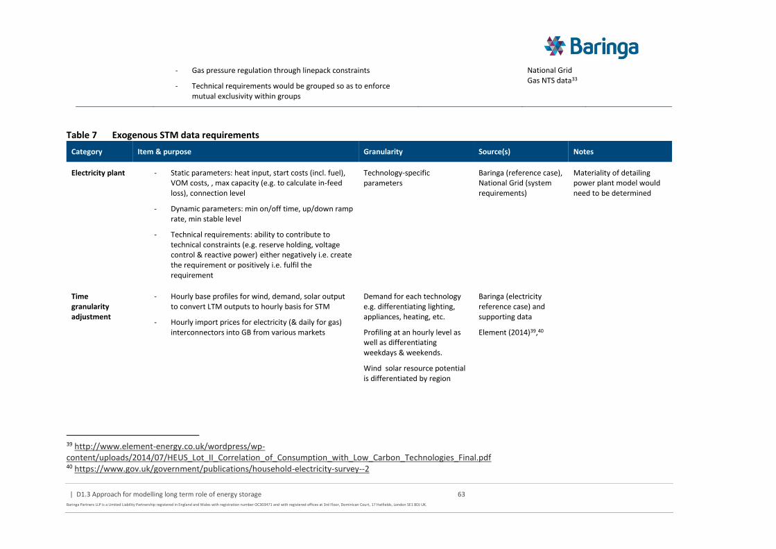
| D1.3 Approach for modelling long term role of energy storage 63
Baringa Partners LLP is a Limited Liability Partnership registered in England and Wales with registration number OC303471 and with registered offices at 3rd Floor, Dominican Court, 17 Hatfields, London SE1 8DJ UK.
- Gas pressure regulation through linepack constraints
- Technical requirements would be grouped so as to enforce mutual exclusivity within groups
National Grid Gas NTS data33
Table 7 Exogenous STM data requirements
Category Item & purpose Granularity Source(s) Notes
Electricity plant - Static parameters: heat input, start costs (incl. fuel), VOM costs, , max capacity (e.g. to calculate in-feed loss), connection level
- Dynamic parameters: min on/off time, up/down ramp rate, min stable level
- Technical requirements: ability to contribute to technical constraints (e.g. reserve holding, voltage control & reactive power) either negatively i.e. create the requirement or positively i.e. fulfil the requirement
Technology-specific parameters
Baringa (reference case), National Grid (system requirements)
Materiality of detailing power plant model would need to be determined
Time granularity adjustment
- Hourly base profiles for wind, demand, solar output to convert LTM outputs to hourly basis for STM
- Hourly import prices for electricity (& daily for gas) interconnectors into GB from various markets
Demand for each technology e.g. differentiating lighting, appliances, heating, etc.
Profiling at an hourly level as well as differentiating weekdays & weekends.
Wind solar resource potential is differentiated by region
Baringa (electricity reference case) and supporting data
Element (2014)39,40
39 http://www.element-energy.co.uk/wordpress/wp-content/uploads/2014/07/HEUS_Lot_II_Correlation_of_Consumption_with_Low_Carbon_Technologies_Final.pdf 40 https://www.gov.uk/government/publications/household-electricity-survey--2

| D1.3 Approach for modelling long term role of energy storage 64
Baringa Partners LLP is a Limited Liability Partnership registered in England and Wales with registration number OC303471 and with registered offices at 3rd Floor, Dominican Court, 17 Hatfields, London SE1 8DJ UK.
Stochastic simulation
Used to simulate variation in key drivers affecting STM operation
- Technical variability e.g. plant unforced outage rates & mean time to repair
- Weather-related variability e.g. wind /solar generation, heating demand (incl. heat pump efficiency) driven by temperature changes
- Market variability e.g. import prices / interconnector availability, fuel and carbon prices
- Behaviour-related variability for e.g. lighting, appliances EV charging windows
Spatial & diurnal Baringa (electricity reference case) and supporting data
Element (2014)39,40
Materiality of weather effects on energy system would need to be assessed
Demand Side Response
- DSR as both load shifting (potential with time window) and load shedding (supply curve of bids).
- Value of lost load for electricity, gas & heat. This would ensure feasibility, even with unserved energy
- Electric vehicle charging windows (under supplier/aggregator managed charging regime)
DSR potential differentiated by technology (e.g. EV, appliances, industry) and available for electricity & gas
London Economics (2011)41,(2013)42
Frontier Economics (2015)36
ETI CVEI project
For other DSR such as heat storage this is a function of LTM capacity and STM operational decisions
System requirements
- Dynamic scaling of system requirements (reserve holding volumes) based on wind and demand forecast errors as well as power plant properties e.g. inertia
- Gas pressure regulation through min and max linepack constraints
- Technical requirements would be grouped so as to enforce mutual exclusivity within groups
Some requirements are system-wide (e.g. frequency), others apply locally.
Baringa, National Grid (SOF)38
National Grid Gas NTS data33
See Deliverable D1.1 for further details
41 https://www.ofgem.gov.uk/ofgem-publications/40961/london-economics-estimating-value-lost-load-final-report-ofgem.pdf 42 https://www.ofgem.gov.uk/sites/default/files/docs/2013/07/london-economics-value-of-lost-load-for-electricity-in-gb_0.pdf

| D1.3 Approach for modelling long term role of energy storage 65
Baringa Partners LLP is a Limited Liability Partnership registered in England and Wales with registration number OC303471 and with registered offices at 3rd Floor, Dominican Court, 17 Hatfields, London SE1 8DJ UK.
7 Scenario framework
7.1 Overview
Once the model and dataset are developed the key purpose of the subsequent analysis is to help answer the research questions 1-4 described in section 2.1.1. To support this we have outlined a scenario framework within which the analysis can take place, as illustrated in section Figure 25.
The previous sections have outlined how uncertainty in both the input assumptions to the LTM and STM could potentially be explored via the use of MC simulation. However, the run-times are almost certainly impractical to apply this to both modules and iterate between them until convergence. It is therefore proposed to only use MC simulation (for a relatively small sample size) for specific STM inputs that are key drivers of uncertainty (with respect to the role of storage). The other key LTM/STM drivers of uncertainty would be used to frame a set of internally consistent, deterministic scenarios within which the MC STM drivers would be explored.
Figure 25 Overarching scenario framework
7.2 Key drivers
The key drivers of STM uncertainty which would be modelled by a MC process within each scenario are variations in each characteristic period in hourly outturn:
Wind generation
Solar generation
Non-weather dependent lighting and appliance electricity demand profiles
Driver 1
Dri
ver
2
Scenario 5 Scenario 6
Scenario 8
Scenario 1 Scenario 2
Scenario 3 Scenario 4
LTM/STM drivers STM drivers
Driver A
Driver B
Central case

| D1.3 Approach for modelling long term role of energy storage 66
Baringa Partners LLP is a Limited Liability Partnership registered in England and Wales with registration number OC303471 and with registered offices at 3rd Floor, Dominican Court, 17 Hatfields, London SE1 8DJ UK.
Temperature dependent heat demand profiles
Prices in electricity and gas interconnected markets
Plant availability due to unforced outages
Indirect DSR potential (e.g. uncertainty around potential EV load shifting potential)
For simplicity it is assumed that there is no (or effectively limited) correlation across these variables, with the potential exception of prices in interconnected markets. It is likely that there is some correlation in wind output and temperature such that where this leads to system stress in GB, the interconnected markets are also likely to exhibit a degree of system stress.
For the LTM/STM drivers of uncertainty that would frame the overarching scenarios we propose to focus on the following core drivers, with the low/high ends of the driver used to frame the scenarios and mid-point the central case:
Driver 1: Long-term cost and availability of storage technologies
Driver 2: Long-term cost and availability of competing flexibility providers (particularly the level of electricity/gas interconnector and LNG capacity). This could also be extended to cover the availability of ‘consumer-led’ flexibility – e.g. restricting the ability of building heat storage to provide further load shifting potential to the electricity system
Driver 3: Increased / decreased difficulty in decarbonising the energy system (e.g. lower CCS/nuclear availability or increased potential for biomass imports)
For other data inputs we would look to anchor around the latest ESME v4.1 reference case assumptions (e.g. long-term energy service demand trends).

| D1.3 Approach for modelling long term role of energy storage 67
Baringa Partners LLP is a Limited Liability Partnership registered in England and Wales with registration number OC303471 and with registered offices at 3rd Floor, Dominican Court, 17 Hatfields, London SE1 8DJ UK.
8 Technical and data architecture
8.1 Technical architecture
LTM
The proposal to adapt the latest ESME model to form the foundation of the LTM means that the technical architecture is already well defined:
AIMMS + CPLEX licences to construct and solve the optimisation problem
SQL database to manage input data/outputs
In addition, the LTM will be required to:
Transform outputs from the STM for use in the LTM for efficient coupling, this will be undertaken primarily through stored procedures and views in the SQL database
STM
For the STM the technical requirements are to:
Construct and solve an MIP/LP43 optimisation problem reflecting the conceptual framework outlined in section 5.2
Efficient management of input data/outputs across multiple simulations
Transform outputs from the LTM for use in the STM for efficient coupling
Generate Monte Carlo samples of – potentially correlated - input data (based on a range of potential different distribution types)
The two main options considered for the STM development are:
Using an extended version of a PLEXOS model. Whilst this is primarily used to reflect NTS-level electricity system dispatch it has potential extensions to cover other energy vectors, such as gas, and has some capability to incorporate additional custom constraints. ESME has previously been linked (via a 1-way intermediate processing spreadsheet) to PLEXOS so that ESME-based electricity system solutions can be explored (via a relatively automated process) from a more detailed operational dispatch perspective. It should be noted that ETI no longer licence PLEXOS.
Creating a bespoke optimisation model in the same AIMMS framework as the LTM
43 Whilst the basic unit commitment problem is a binary integer representation we will look to run the model primarily as an LP (if this is a good approximation of the IP solution) or approximate a “Rounded Relaxation” of the IP, to speed up run times.

| D1.3 Approach for modelling long term role of energy storage 68
Baringa Partners LLP is a Limited Liability Partnership registered in England and Wales with registration number OC303471 and with registered offices at 3rd Floor, Dominican Court, 17 Hatfields, London SE1 8DJ UK.
Table 8 Pros and cons of STM development options
Area Extend PLEXOS Bespoke in AIMMS
Development − Detailed existing representation of electricity system requirements (can mimic energy balance at LDN)
− Gas network add-on (but at extra cost)
− Some level of optimisation constraint customisation possible, but significant risk that this is not sufficient to deliver STM representation (e.g. representation of building heat storage only indirect as a “flexible electricity demand object”)
− Moderate effort required to replicate basic unit commitment and dynamic plant parameter representation already contained in PLEXOS (basic energy balance representation can be adapted from LTM)
− Fully customisable to create STM problem structure
Data management and STM-LTM coupling
− Current version of PLEXOS cannot interface with SQL database, significant overhead in managing inputs/outputs via intermediate Excel sheets or equivalent for both data management and coupling
− As per LTM AIMMS can integrate directly with SQL which makes data management and coupling more efficient.
− If both STM/LTM in AIMMS, overall model process control could be managed more efficiently
MC generator − Some basic MC generation capability, but likely to require generation outside of the model (e.g. correlate non-normal distributions). ETI already use @Risk to do this for ESME
− As per PLEXOS
Licence costs − ~£45k/year for first licence including core version with solver (gas network module £10k additional cost). Additional licences available at significantly lower incremental cost.
− ~€15k upfront cost for AIMMS + solver and ~15% maintenance per year. Note that this is also required for the LTM and we have assumed that it is possible to borrow one of ETI’s existing licences for the duration of the project.
At a high-level the key advantage of PLEXOS is its detailed existing electricity system representation (although noting that we do not need to use the full capability of the software for the purposes of this project). The key disadvantages are the potential lack of flexibility to customise the software in a manner which covers the required multi-vector/network-level STM representation, and the significant overhead in managing data and coupling a PLEXOS-based STM with an AIMMS-based LTM.
The key advantages of AIMMS are lower (or zero) licensing costs, that it provides freedom to develop the STM in line with the proposed requirements, and that using the same basic framework as the LTM/ESME (AIMMS + SQL + @Risk) it would facilitate more efficient development to couple the STM/LTM modules. The downside is that there is not inconsiderable effort required to re-create some of the basic electricity system representation contained in PLEXOS that would be needed for the STM.
On balance, we propose to use AIMMS for the STM development to avoid the potential risk that PLEXOS cannot be adapted sufficiently and to avoid high ongoing licensing costs for ETI (and its members) to continue to use the model internally.

| D1.3 Approach for modelling long term role of energy storage 69
Baringa Partners LLP is a Limited Liability Partnership registered in England and Wales with registration number OC303471 and with registered offices at 3rd Floor, Dominican Court, 17 Hatfields, London SE1 8DJ UK.
The Monte Carlo sample inputs required by the STM would be generated in @Risk as per the current EPN/ESME approach.
NIM
The NIM reflects a standalone generation of LDN network investment cost curves for use in the LTM that should only need to processed infrequently (e.g. if updating the costs of the underlying network components). Our preferred approach as outlined in section 5.4 is to use the ETI’s MEDT.
For reference, if the EPN-based approached were to be used the NAM (Network Analysis Module) which incorporates PSS SINCAL (as the 3rd party software to resolve the steady-state power flow) would need to be adapted for this project; changes include:
Passing a representation of archetypal network topologies into the module (as this is currently fed directly by GIS data for a real world area)
Adapt the output representation to reflect separate demand and supply drivers of reinforcement such that archetypal networks can be aggregated if necessary for use in the LTM without inadvertently netting out underlying reinforcement drivers
User interface and model control
The user interface and model control would be developed in as expedient manner as possible to facilitate analysis with the tool in Stage 2 by the project team (further refinements could be considered beyond this point). It is envisaged that this would encompass:
Control logic within the AIMMS framework to manage the iterative running (and database coordination) so that the STM/LTM can run in an automated manner through to a defined convergence criteria.
A simple Excel sheet would control the generation of the MC sample inputs and write these to the database (this operation only has to happen relatively infrequently) and pull pack a set of pre-defined model outputs into a ‘results dashboard’
For exogenous data inputs it is assumed that these would be inserted directly into the SQL database and not via an Excel/equivalent UI
An overview of the technical architecture is shown in Figure 26.

| D1.3 Approach for modelling long term role of energy storage 70
Baringa Partners LLP is a Limited Liability Partnership registered in England and Wales with registration number OC303471 and with registered offices at 3rd Floor, Dominican Court, 17 Hatfields, London SE1 8DJ UK.
Figure 26 Overview of technical architecture
8.1.1 Out of scope for stage 2
The following items are considered to be out of scope for Stage 2, but could be added to the model framework at a later date
The structure of the STM leads to a number of independent optimisations (by characteristic period and spot year and by Monte Carlo simulation) which is inherently parallelisable and would significantly speed up the performance of the STM (but would require additional solver licenses)
It is envisaged that the database structure will be able to accommodate multiple scenario inputs, however this will not extend in Stage 2 to capturing the results of multiple scenarios in a single database, only that of the active scenario
8.1.2 Software and hardware requirements
3rd-party software requirements include:
AIMMS + CPLEX solver license
SQL Server (it is envisaged that the free Express version is sufficient)
@Risk for Monte Carlo input generation
For the purpose of this project it is proposed to purchase a dedicated modelling machine that can be returned (along with software licenses) to ETI at the end of the project. The specification would be comparable to that EPN (fast multi-core processor with significant - e.g. 64GB+ - memory) as the optimisation problem is again the most computationally intensive part of the model.

| D1.3 Approach for modelling long term role of energy storage 71
Baringa Partners LLP is a Limited Liability Partnership registered in England and Wales with registration number OC303471 and with registered offices at 3rd Floor, Dominican Court, 17 Hatfields, London SE1 8DJ UK.
8.2 Overview of conceptual data model
As ESME will be the starting point for the LTM there is already a detailed physical data model44 (based upon a clear conceptual data model) upon which to build. The LTM and STM are expected to share the same SQL database, but there should be a clear separation of data groups (via e.g. use of different database schemas), covering inputs, transformations, results; as illustrated in Figure 27 where each shaded box represents a separate data group. This includes the option to save the intermediate iteration results, although this is unlikely to be selected by default for every given the potential performance implications of writing significant additional data between iterations.
Figure 27 Conceptual data model
44 A fully-attributed data model of implementation that is dependent upon a specific version of a database (or other data implementation option) and containing the full entity-relationship mapping.

| D1.3 Approach for modelling long term role of energy storage 72
Baringa Partners LLP is a Limited Liability Partnership registered in England and Wales with registration number OC303471 and with registered offices at 3rd Floor, Dominican Court, 17 Hatfields, London SE1 8DJ UK.
9 Private investment perspective
9.1 Overview
The holistic assessment of the long-term role for energy storage is undertaken from the whole system perspective, based on minimising the underlying fundamentals of system. A supplementary task in Stage 2 will provide a high-level assessment of potential issues from a private investment perspective, in a qualitative and semi-quantitative manner in the following areas. This aims to address research questions 5 and 6 described in section 2.1.1.
9.2 Viability of investment and high-level policy options
We propose to select a small number of promising storage examples (up to 3) framed by the system analysis and look at the investment cost profile versus an indirect estimate of the revenue streams suggested by the operational analysis to help understand the potential scale of any ‘missing money’.
This would consider for each spot year:
Wholesale energy arbitrage using prices on an SRMC basis
The marginal value of system technical requirements (e.g. using the shadow price of the relevant constraints) as a proxy for the potential revenue
By combining the outturn operating profiles with the estimated prices across the lifetime of the storage option this would provide an indicative set of revenue streams which can be compared against the investment and operating costs of the storage (including costs of injection).
Depending on the type of storage and its likely operating characteristics we would undertake a high-level assessment of potential ‘generic’ policy options (e.g. availability versus utilisation fees) that could be used to ensure that the investment is viable over its economic life. For example, in a world where capacity for overarching long-term security of supply is cheap and storage is providing relatively infrequent system balancing services it is possible that the estimate of ‘utilisation’ price is not sufficient for storage to recover all of its investment costs without a separate availability payment.
The overarching value of these supplementary payments, to support storage investment, could potentially be tested by seeing whether their total costs are ≤ the opportunity cost to the system solution if the storage options are removed and the pathway is re-optimised.
9.3 Risks or opportunities related to storage deployment
This will provide a qualitative, high-level assessment of other risks/issues that could impact storage deployment insofar as they can be informed by the analysis. For example:
What is the potential for cannibalisation of storage benefits due to large quantities of storage, rapid reductions in costs of future vintages (as per short term analysis in Deliverable D1.2), lumpy investments and/or uncoordinated storage provision across different parts of the energy system

| D1.3 Approach for modelling long term role of energy storage 73
Baringa Partners LLP is a Limited Liability Partnership registered in England and Wales with registration number OC303471 and with registered offices at 3rd Floor, Dominican Court, 17 Hatfields, London SE1 8DJ UK.
Is storage deployment concentrated in areas where the market framework currently does not provide an effective route to market where the benefits of the service the storage is providing can be monetised effectively (e.g. coordination of storage across different parts of the network or use of storage to manage spill of intermittent renewables), and what changes might be required to overcome this?
Does the use of storage suggest potential new services or business models as part of maximising the value from storage from a private investor’s perspective – for example:
Transformation of DNO into a DSO with more active management of both supply and demand with integrated control (direct or via incentives) over storage as part of managing distributed generation curtailment, minimising traditional network reinforcement, etc.
‒ Consumer building control integration with storage (e.g. Powerwall, integrated control of heat storage, etc.) as part of minimising costs in response to more dynamic charging tariffs, or as part of energy arbitrage given surplus PV or other microgeneration

| D1.3 Approach for modelling long term role of energy storage 74
Baringa Partners LLP is a Limited Liability Partnership registered in England and Wales with registration number OC303471 and with registered offices at 3rd Floor, Dominican Court, 17 Hatfields, London SE1 8DJ UK.
Appendix A List of studies reviewed

| D1.3 Approach for modelling long term role of energy storage 75
Baringa Partners LLP is a Limited Liability Partnership registered in England and Wales with registration number OC303471 and with registered offices at 3rd Floor, Dominican Court, 17 Hatfields, London SE1 8DJ UK.
Source Title Filename
ADEME Study of energy storage installation potential ADEME_energy_storage_deployment_potential_full.pdf
DECC Assessing the Impact of low carbon technologies on Great Britain Distribution Networks
smart_grid_forum_keynote_seminar.pdf
Deutsches Institut für Wirtschaftsforschung Belin
Modelling Storage and Demand Management in Electricity Distribution Grids
Berlin_Modeling_storage_DSR_elec_distribution_grid.pdf
EA technology The Transform Model EA_Transform_model_brochure.pdf
EA technology WS3-Ph2 Addendum V1.0 Bug fix 1.0 and data validation
EA_WS3_bug_fixes.pdf
EA technology WS3-Ph2 Addendum V2.0 Scenario data validation EA_WS3_data_bug_fixes.pdf
EA technology WS3 Phase 2 - SOLUTIONS ANNEX EA_WS3_grid_techs_data.pdf
EA technology Work Stream 3 – Phase 3.5 Review of Tipping Point Analysis
EA_WS3_model_data_and_methodology_updates.pdf
EA technology Assessing the Impact of Low Carbon Technologies on Great Britain’s Power Distribution Networks
EA_WS3_report_model_characteristics_results.pdf
Ecole Centrale de Lille Contribution du Stockage a la Gestion Avancee des Systemes Electriques : approches Organisationnelles et Technico-economiques dans les Reseaux de Distribution
ECL_Storage_contribution_to_distribution_grids.pdf
Ecole Centrale de Lille Energy storage systems in distribution grids: New assets to upgrade distribution networks abilities
ECL_CIRED_storage_services_distribution.pdf
Eindhoven University of Technology
A review of multi-energy system planning and optimization tools for sustainable urban development
Eindhoven_review_of_energy_system_models_citywide.pdf
Energy and Environmental Economics
Valuing Energy Storage as a Flexible Resource E3_Valuing_storage_as_flexible_resource.pdf

| D1.3 Approach for modelling long term role of energy storage 76
Baringa Partners LLP is a Limited Liability Partnership registered in England and Wales with registration number OC303471 and with registered offices at 3rd Floor, Dominican Court, 17 Hatfields, London SE1 8DJ UK.
ETH Zurich SCCER-FURIES, WP2: Bulk multi-energy grids Zurich_multi_stage_ESM.pdf
ETH Zurich Valuing Investments in Multi-Energy Conversion, Storage and Demand Side Management Systems under Uncertainty
Zurich_multi-energy_hub_model.pdf
ETH Zurich The impact of wind uncertainty on the strategic valuation of distributed electricity storage
Zurich_storage_valuation_wind_uncertainty.pdf
ETH Zurich Distributed multi-energy-hubs: a review and techno-economic model to assess viability and potential pathways
Zurich_value_multi_energy_hub_under_uncertainty.pdf
Frontier economics A framework for the evaluation of smart grids Frontier_EA_WS2_proposed_approach_and_model_framework.pdf
Grid scientific WORKSTREAM 3 - PHASE 3 TIPPING POINT ANALYSIS REPORT
Grid_scientific_WS3_tipping_point_analysis.pdf
Helsinki University of Technology
Electrical networks and economies of load density Helsinki_elec_network_design_and_cost_based_on_load_density.pdf
Imperial College London Modelling Requirements for Least-Cost and Market-Driven Whole-System Analysis
ICL_modelling_requirement_for_wholeSEM.pdf
Imperial College London Strategic investment in distribution networks with high penetration of small-scale distributed energy resources
CIRED_ICL_distribution_grid_investment_with_high_RES.pdf
Imperial College London Can storage help reduce the cost of a future UK electricity system?
ICL_Carbon_Trust_energy_storage_report.pdf
Imperial College London Strategic Assessment of the Role and Value of Energy Storage Systems in the UK Low Carbon Energy Future
ICL_Carbon_Trust_Role_and_Value_of_Energy_Storage.pdf
Imperial College London Role and Value of Demand Side Response in Reducing the Cost of Transition to a Low Carbon Energy Future
ICL_DSR_to_reduce_cost_of_low_carbon_transition.pdf

| D1.3 Approach for modelling long term role of energy storage 77
Baringa Partners LLP is a Limited Liability Partnership registered in England and Wales with registration number OC303471 and with registered offices at 3rd Floor, Dominican Court, 17 Hatfields, London SE1 8DJ UK.
Imperial College London Whole-system approach to assessing the value of flexible technologies in supporting cost effective integration of renewables
ICL_flex_valuation_integration_RES.pdf
Imperial College London Modelling of Smart Low-Carbon Energy Systems ICL_Models_Descriptions.pdf
Imperial College London Statistical appraisal of economic design strategies of LV distribution networks
ICL_Statistical_appraisal_of_economic_design_LV_networks.pdf
Imperial College London A general spatio-temporal model of energy systems with a detailed account of transport and storage
ICL_STeMES_H2_network.pdf
Imperial College London Optimal design and operation of integrated wind-hydrogen-electricity networks for decarbonising the domestic transport sector in Great Britain
ICL_STeMESwind_H2_for_transport.pdf
Imperial College London Value of Flexibility in a Decarbonised Grid and System Externalities of Low-Carbon Generation Technologies
ICL_CCC_Externalities_report_21Oct2015.pdf
Imperial College London Urban Energy Systems Annual Report 2011/12 ICL_Urban_Energy_Systems_Annual_Report_2011_12.pdf
Joint Research Centre Addressing flexibility in energy system models JRC_Addressing-flexibility-in-energy-system-models.pdf
Joint Research Centre Assessing Storage Value in Electricity Markets JRC_power_storage_value.pdf
National Renewable Energy Laboratory
The Value of Energy Storage for Grid Applications NREL_value_elec_storage_for_grid.pdf
Politechnico di Torino Modelling of multi-energy systems in buildings Turin_Modeling_Multi_energy_systems_buildings.pdf
SANDIA NV Energy Electricity Storage Valuation SANDIA_value_storage_NV_elec_system.pdf
SINTEF Planning of distributed energy systems with parallel infrastructures: A case study
SINTEF_planning_distributed_energy_systems.pdf
Smarter grid solutions Task 3.4: Review of Enablers, Solutions and Top-Down Modelling in TRANSFORM
SGS_WS3_data_review.pdf
Stanford University A Stochastic Programming Framework for the Valuation of Electricity Storage
Stanford_storage_valuation_stochastic_programming.pdf

| D1.3 Approach for modelling long term role of energy storage 78
Baringa Partners LLP is a Limited Liability Partnership registered in England and Wales with registration number OC303471 and with registered offices at 3rd Floor, Dominican Court, 17 Hatfields, London SE1 8DJ UK.
Strategen Consulting White Paper Analysis of Utility-Managed, On-Site Energy Storage in Minnesota
Strategen_Minnesota_storage_valuation.pdf
The University of Manchester
Integrated electrical and gas network modelling for assessment of different power-and-heat options
Manchester_integrated_elec_and_gas_model_for_assessment_of_heat_options.pdf
The University of Manchester
Business cases for distributed multi-energy systems Manchester_business_cases_for_distributed_multi_energy_systems.pdf
The University of Manchester
Demand response services from flexible distributed multi-energy systems
Manchester_DSR_ESM.pdf
The University of Manchester
Flexibility in integrated energy systems and virtual storage
Manchester_flexibility_integrated_energy_systems_and_virtual_storage.pdf
The University of Manchester
Multi-energy systems: modelling and assessing the smart grid beyond electricity
Manchester_smart_grid_beyond_elec.pdf
The University of Manchester
Active Distribution System Management: A Dual-Horizon Scheduling Framework for DSO/TSO Interface under Uncertainty
Manchester_DSO_TSO_interface_scheduling_under_uncertainty.PDF
The University of Manchester
Integrated electrical and gas network flexibility assessment in low-carbon multi-energy systems
Manchester_elec_and_gas_network_flexibility_assessment.pdf
The University of Manchester
Flexible Distributed Multi-Energy Generation System Expansion Planning under Uncertainty
Manchester_multi_energy_hub_planning_operation_model.pdf
The University of Manchester
Integrated modelling and assessment of the operational impact of power-to-gas (P2G) on electrical and gas transmission networks
Manchester_operational_impact_of_power_to_gas_on_elec_and_gas_networks.pdf
The University of Manchester
Multi -energy systems: An overview of concepts and evaluation models
Manchester_review_of_models_for_multi_energy_systems.pdf
TU Wien The importance of distributed storage and conversion technologies in distributed networks on an example of “symbiose”
Wien_CIRED_distributed_multi_energy_storage_symbiose.pdf
Univ. of Las Palmas de Gran Canaria
Simulation of Storage Systems for increasing the Power Quality of Renewable Energy Sources
Canarias_storage_for_power_quality_RES.pdf

| D1.3 Approach for modelling long term role of energy storage 79
Baringa Partners LLP is a Limited Liability Partnership registered in England and Wales with registration number OC303471 and with registered offices at 3rd Floor, Dominican Court, 17 Hatfields, London SE1 8DJ UK.
University College Cork Assessing power system security. A framework and a multi model approach
UCC_Assessing-power-system-security_IT.pdf
University College Dublin Distributed vs. Centralized Energy Storage for Power System Applications
UCD_Distributed_vs_Centralized_Energy_Storage_for_Power_Sytsem_Applications.pdf
University College London Spatially and Temporally Explicit Energy System Modelling to Support the Transition to a Low Carbon Energy Infrastructure – Case Study for Wind Energy in the UK
UCL_UKTM_linking_to_power_dispath_model_RES.pdf
University College London DynEMO: A Dynamic Energy Model for the Exploration of Energy, Society and Environment
UCL_DynEMo.pdf
University of Cambridge Distributed Generation, Storage, Demand Response, and Energy Efficiency as Alternatives to Grid Capacity Enhancement
Cambridge_storage_for_network_investment_deferral.pdf
University of Central Lancashire
A SPEA2 Based Planning Framework for Optimal Integration of Distributed Generations
Lancashire_planning_model_for_integration_of_DG.pdf
University of Grenoble Development of a dispatch model of the European power system for coupling with a long-term foresight energy model
Grenoble_Coupled_power_dispatch_LT_energy_models.pdf
University of Michigan Valuation of Energy Storage: An Optimal Switching Approach
Michigan_storage_valuation_financial_instruments.pdf