PROGRAMMABLE STEPPING MOTOR CONTROLLERS · DOVER MOTION’s DOVER MOTION-300 Series Programmable...
232
DOVER MOTION-300 SERIES PROGRAMMABLE STEPPING MOTOR CONTROLLERS OPERATOR’S MANUAL Revision 1.03 Part # 1030013 For Firmware Release 2.5.2
Transcript of PROGRAMMABLE STEPPING MOTOR CONTROLLERS · DOVER MOTION’s DOVER MOTION-300 Series Programmable...

DOVER MOTION-300 SERIES
PROGRAMMABLE
STEPPING MOTOR CONTROLLERS
OPERATOR’S MANUAL
Revision 1.03
Part # 1030013
For Firmware Release 2.5.2


DOVER MOTION-300 Series
Operator’s Manual Revision 1.03, Firmware Version 2.5.2 iii
This Manual contains instructions for the installation, operation and maintenance of
DOVER MOTION’s DOVER MOTION-300 Series Programmable Stepping Motor
Controllers.
Please read this manual carefully to ensure correct usage of the system. We recommend
that you keep this manual near the system as a reference.
Trademark Acknowledgments
All trademarks and product names mentioned are properties of their respective
companies, and are recognized and acknowledged as such by DOVER MOTION.
Copyright
Manual Revision 1.03
Copyright © 1995 DOVER MOTION, 159 Swanson Road, Boxborough, MA 01719, U.S.A. All rights reserved. Reproduction or use, without express written permission from DOVER MOTION and/or its licenser, of any portion of this manual is prohibited.
Disclaimer
While every effort has been made to ensure that the information in this manual is
complete, accurate and up-to-date, DOVER MOTION assumes no liability for damages
resulting from any errors or omissions in this manual, or from the use of the information
contained herein. DOVER MOTION reserves the right to revise this manual without
obligation to notify any person or organization of the revision.
In no event will DOVER MOTION be liable for direct, indirect, special, incidental, or
consequential damages arising out of the use of or the inability to use this manual.

DOVER MOTION-300 Series
iv Revision 1.03, Firmware Version 2.5.2 Operator’s Manual

DOVER MOTION-300 Series
Operator’s Manual Revision 1.03, Firmware Version 2.5.2 v
Overview
Scope of Manual
This manual contains information and instructions for setting up and operating DOVER
MOTION’s DOVER MOTION-300 Series Programmable Stepping Motor Controllers.
Setup
For a fast start, see Section 2. Material on setting up specific functions is found
throughout the manual.
Ordering Cables
Contact Customer Service (see below).
Returning Equipment
Contact Customer Service (see below) to obtain a Return Authorization (RA) number.
Refer to Section 17 for return policy and packing and shipping instructions.
Customer Service
Telephone: 508-475-3400
Email: [email protected]
Shipping Address: DOVER MOTION
159 Swanson Road,
Boxborough, MA 01719

DOVER MOTION-300 Series
vi Revision 1.03, Firmware Version 2.5.2 Operator’s Manual

DOVER MOTION-300 Series
Operator’s Manual Revision 1.03, Firmware Version 2.5.2 vii
Table of Contents
Section Page
A Message From DOVER MOTION’s President ..........................................Error! Bookmark not defined.
Overview ........................................................................................................................................................ v
Table of Commands...................................................................................................................................... xi
List of Figures ............................................................................................................................................. xiv
List of Tables ................................................................................................................................................ xv
1. Introduction ...................................................................................................................................... 1-1
1.1. User Feedback ................................................................................................................................1-1
1.2. Unpacking ......................................................................................................................................1-1
2. Getting Started ................................................................................................................................. 2-1
2.1. Overall System Configuration ........................................................................................................2-1
2.2. Interfacing to DOVER MOTION Positioning Stages ....................................................................2-3
2.3. Operating Other Stages ..................................................................................................................2-5
2.4. Communication ..............................................................................................................................2-9
2.4.1. Terminal Operation...............................................................................................................2-9
2.4.2. IBM PC/Compatible Operation ..........................................................................................2-13
3. Motor Wiring and Drive ................................................................................................................. 3-1
3.1. About Motors .................................................................................................................................3-1
3.1.1. DOVER MOTION Stepping Motor Ratings ........................................................................3-1
3.1.2. Four (“Two”)–Phase Stepping Motors .................................................................................3-2
3.1.3. Full Coil Versus Half Coil ....................................................................................................3-4
3.1.4. 8-Wire and 4-Wire Motors ...................................................................................................3-5
3.1.5. Midrange Resonance Suppression ........................................................................................3-5
3.2. The DOVER MOTION Motor Connection .....................................................................................3-6
3.3. Current Setting ...............................................................................................................................3-8
3.3.1. Main Current and Reduced Idle Current ...............................................................................3-8
3.3.2. Current and Resistance .........................................................................................................3-8
3.3.3. Calculating the Main Current Dip-Switch Setting ..............................................................3-10
3.3.4. Calculating the Reduced Current Set Resistance Setting ...................................................3-12
3.3.5. Accessing the Dip-Switches................................................................................................3-13

DOVER MOTION-300 Series
viii Revision 1.03, Firmware Version 2.5.2 Operator’s Manual
4. The Front Panel ................................................................................................................................ 4-1
4.1. Baud Rate Selection ...................................................................................................................... 4-1
4.2. Handshaking .................................................................................................................................. 4-3
4.2.1. Hardware and Software Handshaking .................................................................................. 4-3
4.2.2. DTR/DSR Handshaking ....................................................................................................... 4-4
4.3. Program Select .............................................................................................................................. 4-5
4.4. Jog Functions ................................................................................................................................. 4-5
4.5. Programmed Wait for Start ........................................................................................................... 4-7
4.6. Master Reset .................................................................................................................................. 4-7
4.7. GPIB Enable and Address ............................................................................................................. 4-8
4.8. Selecting a Communications Port .................................................................................................. 4-8
5. Serial Communication ..................................................................................................................... 5-1
5.1. Serial Port Configuration ............................................................................................................... 5-1
5.2. PC Control ..................................................................................................................................... 5-3
5.2.1. Immediate versus Program Modes ....................................................................................... 5-3
5.2.2. Polling versus Interrupt Modes ............................................................................................ 5-4
5.2.3. Example Programs ............................................................................................................... 5-5
5.2.4. Debugging Programs.......................................................................................................... 5-12
6. GPIB (IEEE–488) Parallel Port ...................................................................................................... 6-1
7. DOVER MOTION-300 Command Set ........................................................................................... 7-1
7.1. Command Syntax .......................................................................................................................... 7-1
7.1.1. General ................................................................................................................................. 7-1
7.1.2. User Units ............................................................................................................................ 7-2
7.1.3. Bit-Masks ............................................................................................................................. 7-2
7.1.4. Input Code Parameters ......................................................................................................... 7-4
7.2. Command Summary ...................................................................................................................... 7-8
7.3. Detailed Command Descriptions ................................................................................................. 7-11
7.3.1. Memory Commands ........................................................................................................... 7-11
7.3.2. Move Commands ............................................................................................................... 7-16
7.3.3. Report Commands ............................................................................................................. 7-20
7.3.4. Set Commands ................................................................................................................... 7-32
7.3.5. Homing Commands ........................................................................................................... 7-35
7.3.6. Trajectory Commands ........................................................................................................ 7-39
7.3.7. Execution Commands ........................................................................................................ 7-45
7.3.8. Wait Commands ................................................................................................................. 7-46
7.3.9. Program Flow Commands .................................................................................................. 7-49
7.3.10. Default Commands ............................................................................................................ 7-52
7.3.11. Communication Configuration Commands ........................................................................ 7-55
7.3.12. Motor Current Commands ................................................................................................. 7-64
7.3.13. Joystick Commands ........................................................................................................... 7-66
7.3.14. Miscellaneous Commands ................................................................................................. 7-72

DOVER MOTION-300 Series
Operator’s Manual Revision 1.03, Firmware Version 2.5.2 ix
8. Immediate Mode .............................................................................................................................. 8-1
9. Program Mode ................................................................................................................................. 9-1
9.1. Creating Programs ..........................................................................................................................9-1
9.2. Displaying a List of Programs ........................................................................................................9-2
9.3. Viewing a Program.........................................................................................................................9-3
9.4. Running Programs ..........................................................................................................................9-3
9.4.1. From the DOVER MOTION-300 .........................................................................................9-3
9.4.2. From a PC .............................................................................................................................9-4
9.5. Deleting Programs ..........................................................................................................................9-4
9.6. Editing Programs ............................................................................................................................9-5
9.7. Program Structure ..........................................................................................................................9-6
9.7.1. Comments .............................................................................................................................9-6
9.7.2. Axis Control .........................................................................................................................9-6
9.7.3. Repetitive Iterations within Programs ...................................................................................9-6
9.8. Errors and Debugging ....................................................................................................................9-9
10. Limit And Home Switches ............................................................................................................. 10-1
10.1. Hardware Considerations ........................................................................................................10-1
10.2. Software Implementation.........................................................................................................10-2
11. Input And Output Lines ................................................................................................................ 11-1
11.1. Pin Assignments ......................................................................................................................11-1
11.2. Setting Outputs and Reading Inputs ........................................................................................11-2
11.3. Applications ............................................................................................................................11-3
11.4. Voltage and Impedance ...........................................................................................................11-3
12. Encoder Interface .......................................................................................................................... 12-1
12.1. Pins and Channels ...................................................................................................................12-1
12.2. Preventing Cable Noise ...........................................................................................................12-1
12.3. Reading and Setting the Encoder Position ...............................................................................12-2
12.4. Quasi-Closed Loop Moves ......................................................................................................12-2
13. Joystick Interface ........................................................................................................................... 13-1
13.1. Concept ...................................................................................................................................13-1
13.2. Connections .............................................................................................................................13-1
13.3. Reading and Setting Joystick Values .......................................................................................13-1
13.4. Switches ..................................................................................................................................13-3
14. The DOVER MOTION 300 Series Relay PCB Switch ............................................................... 14-1
15. Default States ................................................................................................................................. 15-1
16. Connector Pin-outs ........................................................................................................................ 16-1

DOVER MOTION-300 Series
x Revision 1.03, Firmware Version 2.5.2 Operator’s Manual
17. Miscellaneous .................................................................................................................................. 17-1
17.1. Mounting and Cooling Provisions .......................................................................................... 17-1
17.2. Power Issues: Changing Fuses, and Converting to 230 Volt 50/60 Hz Operation ................. 17-1
17.3. DOVER MOTION-300 Help Diskette ................................................................................... 17-3
17.3.1. Diskette Contents ............................................................................................................... 17-3
17.3.2. UP.EXE and DOWN.EXE ................................................................................................. 17-6
17.3.3. DOVER MOTION–300 Command-Language Programs on the DOVER MOTION–300
Help Diskette .................................................................................................................................. 17-11
17.4. Bit-Mask Value Table .......................................................................................................... 17-15
17.5. Motion Calculations.............................................................................................................. 17-19
17.6. Return Procedures................................................................................................................. 17-22
17.7. Packaging and Shipping........................................................................................................ 17-23
17.8. Terms and Conditions ........................................................................................................... 17-25
17.9. DOVER MOTIONness Report .............................................................................................. 17-27
Index ............................................................................................................................................................ I-1
DOVER MOTION-300 Series
Operator’s Manual Revision 1.03, Firmware Version 2.5.2 xi
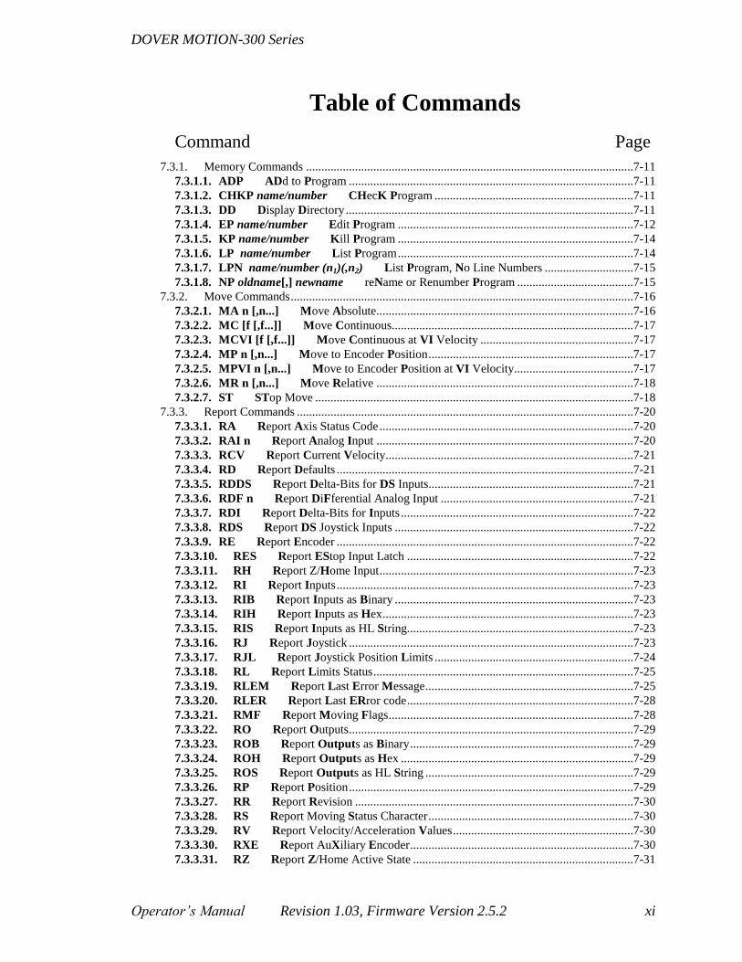
Table of Commands
Command Page
7.3.1. Memory Commands ...........................................................................................................7-11
7.3.1.1. ADP ADd to Program .............................................................................................7-11
7.3.1.2. CHKP name/number CHecK Program .................................................................7-11
7.3.1.3. DD Display Directory ..............................................................................................7-11
7.3.1.4. EP name/number Edit Program .............................................................................7-12
7.3.1.5. KP name/number Kill Program .............................................................................7-14
7.3.1.6. LP name/number List Program .............................................................................7-14
7.3.1.7. LPN name/number (n1)(,n2) List Program, No Line Numbers .............................7-15
7.3.1.8. NP oldname[,] newname reName or Renumber Program ......................................7-15
7.3.2. Move Commands ................................................................................................................7-16
7.3.2.1. MA n [,n...] Move Absolute ....................................................................................7-16
7.3.2.2. MC [f [,f...]] Move Continuous...............................................................................7-17
7.3.2.3. MCVI [f [,f...]] Move Continuous at VI Velocity ..................................................7-17
7.3.2.4. MP n [,n...] Move to Encoder Position ...................................................................7-17
7.3.2.5. MPVI n [,n...] Move to Encoder Position at VI Velocity .......................................7-17
7.3.2.6. MR n [,n...] Move Relative ....................................................................................7-18
7.3.2.7. ST STop Move ........................................................................................................7-18
7.3.3. Report Commands ..............................................................................................................7-20
7.3.3.1. RA Report Axis Status Code ...................................................................................7-20
7.3.3.2. RAI n Report Analog Input ....................................................................................7-20
7.3.3.3. RCV Report Current Velocity .................................................................................7-21
7.3.3.4. RD Report Defaults .................................................................................................7-21
7.3.3.5. RDDS Report Delta-Bits for DS Inputs...................................................................7-21
7.3.3.6. RDF n Report DiFferential Analog Input ...............................................................7-21
7.3.3.7. RDI Report Delta-Bits for Inputs ............................................................................7-22
7.3.3.8. RDS Report DS Joystick Inputs ..............................................................................7-22
7.3.3.9. RE Report Encoder .................................................................................................7-22
7.3.3.10. RES Report EStop Input Latch ..........................................................................7-22
7.3.3.11. RH Report Z/Home Input ...................................................................................7-23
7.3.3.12. RI Report Inputs .................................................................................................7-23
7.3.3.13. RIB Report Inputs as Binary ..............................................................................7-23
7.3.3.14. RIH Report Inputs as Hex ..................................................................................7-23
7.3.3.15. RIS Report Inputs as HL String..........................................................................7-23
7.3.3.16. RJ Report Joystick .............................................................................................7-23
7.3.3.17. RJL Report Joystick Position Limits .................................................................7-24
7.3.3.18. RL Report Limits Status .....................................................................................7-25
7.3.3.19. RLEM Report Last Error Message ....................................................................7-25
7.3.3.20. RLER Report Last ERror code ..........................................................................7-28
7.3.3.21. RMF Report Moving Flags ................................................................................7-28
7.3.3.22. RO Report Outputs .............................................................................................7-29
7.3.3.23. ROB Report Outputs as Binary .........................................................................7-29
7.3.3.24. ROH Report Outputs as Hex ............................................................................7-29
7.3.3.25. ROS Report Outputs as HL String ....................................................................7-29
7.3.3.26. RP Report Position .............................................................................................7-29
7.3.3.27. RR Report Revision ...........................................................................................7-30
7.3.3.28. RS Report Moving Status Character ...................................................................7-30
7.3.3.29. RV Report Velocity/Acceleration Values ...........................................................7-30
7.3.3.30. RXE Report AuXiliary Encoder .........................................................................7-30
7.3.3.31. RZ Report Z/Home Active State ........................................................................7-31

DOVER MOTION-300 Series
xii Revision 1.03, Firmware Version 2.5.2 Operator’s Manual
7.3.4. Set Commands ................................................................................................................... 7-32
7.3.4.1. SAXD Save AXis Defaults ..................................................................................... 7-32
7.3.4.2. SD Save Defaults .................................................................................................... 7-32
7.3.4.3. SE n [,n...] Set Encoder .......................................................................................... 7-33
7.3.4.4. SO i[,i] Set Outputs ................................................................................................ 7-33
7.3.4.5. SP n [,n...] Set Position .......................................................................................... 7-34
7.3.4.6. SR Set Relay ........................................................................................................... 7-34
7.3.4.7. SXCH n [,f] Set AuXiliary Encoder Input CHannel .............................................. 7-34
7.3.4.8. SXE i[,i] Set Auxiliary Encoder .............................................................................. 7-35
7.3.5. Homing Commands ........................................................................................................... 7-35
7.3.5.1. HA n [,n...] Homing Acceleration .......................................................................... 7-35
7.3.5.2. HDST n [,n...] Homing Search DiSTance .............................................................. 7-36
7.3.5.3. HF n [,n...] Homing Velocity Final ........................................................................ 7-36
7.3.5.4. HI n [,n...] Homing Velocity Initial ....................................................................... 7-37
7.3.5.5. HM n [,n...] Homing Mode .................................................................................... 7-38
7.3.5.6. MH [f,[f,...]] Move Home ...................................................................................... 7-39
7.3.5.7. ZHMP Z/HoMe Input Polarity .............................................................................. 7-39
7.3.6. Trajectory Commands ........................................................................................................ 7-39
7.3.6.1. AC n [,n...] ACceleration ....................................................................................... 7-40
7.3.6.2. BA n [,n...] Jog Button Acceleration ...................................................................... 7-40
7.3.6.3. BF n [,n...] Jog Button Velocity Final .................................................................... 7-41
7.3.6.4. BI n [,n...] Jog Button Velocity Initial .................................................................... 7-42
7.3.6.5. VF n [,n...] Velocity Final ...................................................................................... 7-42
7.3.6.6. VI n [,n...] Velocity Initial ...................................................................................... 7-43
7.3.6.7. VSET n Select Velocity SET ................................................................................... 7-44
7.3.7. Execution Commands ........................................................................................................ 7-45
7.3.7.1. XP name/number eXecute Program ...................................................................... 7-45
7.3.7.2. XS name/number eXecute Program Single step .................................................... 7-46
7.3.8. Wait Commands ................................................................................................................. 7-46
7.3.8.1. PAUC 'c' I n PAUse program on Character .......................................................... 7-46
7.3.8.2. PAUI i[,i] PAUse program on Input ....................................................................... 7-47
7.3.8.3. PAUL i[,i] PAUse program on input Level ............................................................ 7-47
7.3.8.4. PAUM f PAUse Message enable ........................................................................... 7-47
7.3.8.5. PAUS f PAUse program on Start button ................................................................ 7-48
7.3.8.6. WC (c) Wait for Character ..................................................................................... 7-48
7.3.8.7. WI i[,i] WaiT for Input ......................................................................................... 7-48
7.3.8.8. WS Wait for Start Button ....................................................................................... 7-49
7.3.8.9. WT nnn WaiT for Given # of Msec ....................................................................... 7-49
7.3.9. Program Flow Commands .................................................................................................. 7-49
7.3.9.1. BS name Begin Subroutine ..................................................................................... 7-49
7.3.9.2. CS lbl[,n] Call Subroutine ...................................................................................... 7-49
7.3.9.3. CSI lbl,i[,i][,n] Call Subroutine on Input ............................................................... 7-50
7.3.9.4. EM End of Main Program ...................................................................................... 7-51
7.3.9.5. ES [name] End Subroutine ..................................................................................... 7-51
7.3.9.6. JP n/s JumP to Label or Line # .............................................................................. 7-51
7.3.9.7. JPI lbl,i[,i] JumP on Input .................................................................................... 7-52
7.3.10. Default Commands ............................................................................................................ 7-52
7.3.10.1. ARP n Auto Run Program ................................................................................. 7-52
7.3.10.2. LIMP 1/0[,1/0…] LIMit Polarity .................................................................... 7-53
7.3.10.3. LS E/D Limit Stop, All Axes ............................................................................ 7-53
7.3.10.4. LSA 1/0[,1/0…] Limit Stop, Per Axis .............................................................. 7-54
7.3.10.5. MF E/D Move Finished .................................................................................... 7-54
7.3.10.6. RESET RESET Controller................................................................................ 7-54

DOVER MOTION-300 Series
Operator’s Manual Revision 1.03, Firmware Version 2.5.2 xiii
7.3.11. Communication Configuration Commands .........................................................................7-55
7.3.11.1. BRT n[,1/0] Baud RaTe .....................................................................................7-55
7.3.11.2. CMDI n CoMmanD Input Port Select ...............................................................7-55
7.3.11.3. GADRn GPIB ADdRess ....................................................................................7-56
7.3.11.4. GLTF f GPIB Line Terminator Flag ..................................................................7-56
7.3.11.5. GSRB n GPIB SRQ Bits Mask ...........................................................................7-57
7.3.11.6. GTRM n GPIB TeRMinal Mode ......................................................................7-61
7.3.11.7. HHSK E/D Hardware HandShaKe Mode ..........................................................7-61
7.3.11.8. SHSK E/D Software HandShaKe Mode ............................................................7-62
7.3.11.9. TERM n TERMinal Mode ................................................................................7-62
7.3.12. Motor Current Commands ..................................................................................................7-64
7.3.12.1. IC E/D Idle Current, All Axes ............................................................................7-64
7.3.12.2. ICA E/D Idle Current, Per Axis .........................................................................7-64
7.3.12.3. IDL [n] Idle Current DeLay, All Axes ...............................................................7-64
7.3.12.4. IDLA [n] Idle Current DeLay, per Axis .............................................................7-65
7.3.12.5. MCUR E/D Motor Output CURrent .................................................................7-65
7.3.13. Joystick Commands ............................................................................................................7-66
7.3.13.1. JA n [,n...] Joystick Acceleration .......................................................................7-66
7.3.13.2. JC n [,n...] Joystick Center Value ......................................................................7-66
7.3.13.3. JD n [,n...] Joystick Deadband ...........................................................................7-67
7.3.13.4. JE [f [,f...]] Joystick Enable ...............................................................................7-67
7.3.13.5. JG n [,n...] Joystick Gain ...................................................................................7-67
7.3.13.6. JIC n [,n...] Joystick Input Channel ...................................................................7-68
7.3.13.7. JMAX n [,n...] Joystick MAXimum Input Limit ...............................................7-68
7.3.13.8. JMIN n [,n...] Joystick MINimum Input Limit..................................................7-69
7.3.13.9. JNL n [,n...] Joystick Negative Position Limit ..................................................7-69
7.3.13.10. JPL n [,n...] Joystick Positive Position Limit ....................................................7-70
7.3.13.11. JQI s [,s...] Joystick Qualifier Input ...................................................................7-70
7.3.13.12. JZ [f [,f...]] Joystick Auto-Zero ..........................................................................7-71
7.3.14. Miscellaneous Commands ..................................................................................................7-72
7.3.14.1. AA Select All Axes Mode...................................................................................7-72
7.3.14.2. Ax Select Single Axis Mode ...............................................................................7-72
7.3.14.3. DC (c) Display Character ...................................................................................7-73
7.3.14.4. DS (string) Display String ..................................................................................7-73
7.3.14.5. DSN (string) Display String, No LF ...................................................................7-74
7.3.14.6. HELP[s] Show HELP Screen ............................................................................7-74
7.3.14.7. IOBN Select Current I/O-Board Number ...........................................................7-74
7.3.14.8. LPUP f [,f...] Limit PullUP/down ......................................................................7-74
7.3.14.9. UU n [,n...] User Units ........................................................................................7-75

DOVER MOTION-300 Series
xiv Revision 1.03, Firmware Version 2.5.2 Operator’s Manual
List of Figures
Figure Page
Figure 2-1 LIMIT/ENCODER CONNECTOR PIN-OUT ........................................ 2-5
Figure 2-2 MOTOR CONNECTOR PIN-OUT.......................................................... 2-6
Figure 2-3 SERIAL PORT CONNECTOR PIN-OUT ............................................ 2-10
Figure 3-1 FOUR-PHASE MOTOR COILS AND LEADS ...................................... 3-3
Figure 3-2 MOTOR CONNECTOR PIN-OUT.......................................................... 3-7
Figure 5-1 SERIAL PORT CONNECTOR PIN-OUT .............................................. 5-2
Figure 10-1 LIMIT/ENCODER CONNECTOR PIN-OUT .................................... 10-1
Figure 11-1 DIGITAL I/O CONNECTOR PIN-OUT ............................................. 11-1
Figure 16-1 SERIAL PORT CONNECTOR PIN-OUT .......................................... 16-2
Figure 16-2 DIGITAL I/O CONNECTOR PIN-OUT ............................................. 16-3
Figure 16-3 MOTOR CONNECTOR PIN-OUT...................................................... 16-4
Figure 16-4 LIMIT/ENCODER CONNECTOR PIN-OUT .................................... 16-5
Figure 16-5 JOYSTICK CONNECTOR PIN-OUT ................................................. 16-6
Figure 16-6 GPIB CONNECTOR (IEEE–488) PIN-OUT ...................................... 16-7
DOVER MOTION-300 Series
Operator’s Manual Revision 1.03, Firmware Version 2.5.2 xv
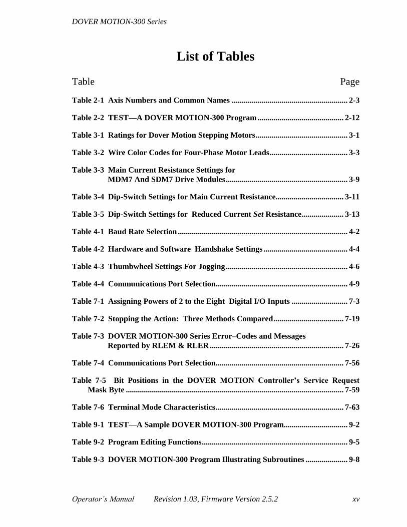
List of Tables
Table Page
Table 2-1 Axis Numbers and Common Names .......................................................... 2-3
Table 2-2 TEST—A DOVER MOTION-300 Program ........................................... 2-12
Table 3-1 Ratings for Dover Motion Stepping Motors .............................................. 3-1
Table 3-2 Wire Color Codes for Four-Phase Motor Leads ....................................... 3-3
Table 3-3 Main Current Resistance Settings for
MDM7 And SDM7 Drive Modules ............................................................. 3-9
Table 3-4 Dip-Switch Settings for Main Current Resistance.................................. 3-11
Table 3-5 Dip-Switch Settings for Reduced Current Set Resistance ..................... 3-13
Table 4-1 Baud Rate Selection ..................................................................................... 4-2
Table 4-2 Hardware and Software Handshake Settings .......................................... 4-4
Table 4-3 Thumbwheel Settings For Jogging ............................................................. 4-6
Table 4-4 Communications Port Selection .................................................................. 4-9
Table 7-1 Assigning Powers of 2 to the Eight Digital I/O Inputs ............................ 7-3
Table 7-2 Stopping the Action: Three Methods Compared ................................... 7-19
Table 7-3 DOVER MOTION-300 Series Error–Codes and Messages
Reported by RLEM & RLER ................................................................... 7-26
Table 7-4 Communications Port Selection ................................................................ 7-56
Table 7-5 Bit Positions in the DOVER MOTION Controller’s Service Request
Mask Byte ............................................................................................................. 7-59
Table 7-6 Terminal Mode Characteristics ................................................................ 7-63
Table 9-1 TEST—A Sample DOVER MOTION-300 Program................................ 9-2
Table 9-2 Program Editing Functions ......................................................................... 9-5
Table 9-3 DOVER MOTION-300 Program Illustrating Subroutines ..................... 9-8

DOVER MOTION-300 Series
xvi Revision 1.03, Firmware Version 2.5.2 Operator’s Manual
Table 15-1 Command Parameter Queries & Defaults ............................................. 15-2
Table 17-1 TEST.3X0 Program on the DOVER MOTION-300 Help Diskette .. 17-11
Table 17-2 TEST1.3X0 Program on the DOVER MOTION-300 Help Diskette 17-12
Table 17-3 TEST2.3X0 Program on the DOVER MOTION-300 Help Diskette 17-13
Table 17-4 TEST3.3X0 Program on the DOVER MOTION-300 Help Diskette 17-14
Table 17-5 Bit-Mask Values Representing Eight Numbers .................................. 17-16

DOVER MOTION-300 Series Introduction
Operator’s Manual Revision 1.03, Firmware Version 2.5.2 1-1
1. Introduction
This manual details the operation of the DOVER MOTION-300 Series Programmable
Stepping Motor Controllers. Models in the series provide programmable control of two
to four (models 320 through 340) stepping motors. They produce Step, Direction, and
Enable signals for each axis. The DOVER MOTION-300 Series can function as a pre-
programmed motion controller, or may be operated as an intelligent slave to a host
computer via its RS-232 and GPIB communication ports.
1.1. User Feedback
We have attempted to write this manual in a clear and thorough fashion, and trust that all
topics have been covered in appropriate detail. Feel free to contact us (508-475-3400)
with any questions or suggestions to improve its readability.
The software and hardware design of the DOVER MOTION-300 is itself a result of
customer feedback on preceding products over the years. In several cases (such as dual
use of the START/STOP buttons as JOG buttons, and the inclusion of front panel
PROGRAM SELECT thumbwheels), design enhancements occurred as a direct result of
customer requests. We solicit your ideas for future product improvements.
1.2. Unpacking
Upon receipt, carefully unpack the shipping container and inspect all its contents. Any
visible damage—including damage to the container itself—will require that a damage
claim be filed with the shipper. We recommend that you retain the shipping container
and packing materials, in the event that the controller will later be reshipped. The
following items should be present:
1. DOVER MOTION-300 Series unit
2. Operator’s manual
3. Six-foot RS-232 serial cable
4. 115 Volt modular AC power cord
5. 3 ½" MS-DOS Terminal Emulator and Help Diskette
If any items are missing, contact our Customer Service department immediately at
508-475-3400. The DOVER MOTION-300 Series is warranted for a period of one year
from date of shipment. Specific details on DOVER MOTION’s warranty policy and
servicing are available in Section 17 of this manual.
While initially set for 115 volt operation, the DOVER MOTION-300 Series can be
readily set to operate on 220-volt AC mains. In addition, we can supply modular
AC line cords to allow direct connection to the wall outlets of most countries. See

Introduction DOVER MOTION-300 Series
1-2 Revision 1.03, Firmware Version 2.5.2 Operator’s Manual
Power Issues: Changing Fuses, and Converting to 230 Volt 50/60 Hz Operation in
Section 17.

DOVER MOTION-300 Series Introduction
Operator’s Manual Revision 1.03, Firmware Version 2.5.2 1-3


DOVER MOTION-300 Series Getting Started
Operator’s Manual Revision 1.03, Firmware Version 2.5.2 2-1
2. Getting Started
In designing the DOVER MOTION-300, we have tried to retain a simple, easy-to-use
operator interface, while providing the advanced features needed to meet complex
motion-control requirements. Describing those features in detail is the function of this
manual. Since most people will want to try out the DOVER MOTION-300 before
thoroughly absorbing the contents of this manual, we have included this section to get
you up and running with a minimum of effort. With very few exceptions, the command
interface is the same as that employed in all other DOVER MOTION motion controllers;
if you have had any prior experience with these products, learning to use the DOVER
MOTION-300 Series will be very easy and familiar.
Before proceeding, please review the following precautions:
1. When connecting or disconnecting any cable, be sure to turn off the AC power and
allow ten seconds for internal voltages to bleed down.
2. Ensure all cables are securely connected, using any jackscrews, before applying
power.
3. Ensure that the power cord is connected to a grounded (3 prong) AC receptacle. We
recommend using a dedicated outlet to minimize any power fluctuations. We also
recommend using a ground-fault-protected outlet if there is any potential for moisture
build-up near the user.
4. The fan inlet filter should be cleaned monthly. Turn off power and disconnect the
power cord. Remove the four 6-32 flat allen-head screws that hold the filter cover in
place. Remove the filter and clean with water and a mild detergent. Thoroughly dry
the filter before re-installing. The DOVER MOTION-300 should not be operated in
excessively dusty environments.
2.1. Overall System Configuration
The DOVER MOTION-300 Series of multi-axis stepping motor controllers are one
component of a complete motion system. They control and drive two to four stepping
motors (depending on the specific model).
Another system component will consist of the positioning stages themselves, which from
an electrical standpoint consist of a stepping motor, a pair of limit switches, and possibly
an encoder. In some systems, a host computer will also be present, although the DOVER
MOTION-300 Series is capable of stand-alone, pre-programmed operation. Finally, a
joystick can be connected to the DOVER MOTION-300 for manual analog control, and a
variety of external customer-specific devices can be monitored and controlled by the
programmable I/O lines of the DOVER MOTION-300 Series unit.
Getting Started DOVER MOTION-300 Series
2-2 Revision 1.03, Firmware Version 2.5.2 Operator’s Manual
It may be helpful to contrast the above configuration with the two other popular motion
control systems. One approach, used in our DOVER MOTION-500 Series controllers
and DOVER MOTION-100 Series drivers, separates the functions of logic-level control
and high power microstepping drives. This provides a less integrated solution, but allows
a choice of stepping motor drivers—a custom drive, pre-existing or preferred driver can
be used in place of the DOVER MOTION-100 Series driver. Also, the 500-Series allows
logic-level control for up to 12 axes housed in a single enclosure, whereas such compact
grouping is physically inconvenient for more than four axes when the drives are included
as well.
The other popular system configuration places the logic-level control electronics on a
plug-in card, which is installed within a host computer. In this design, used in our
DOVER MOTION-PCX Series, an external stepping motor driver is again a necessity. In
addition, since a potentially large number of cables must be connected to the plug-in card,
and limited connector space is available, a breakout box is usually required. This serves
as a “Grand Central Station” to simplify the routing of a number of limit, encoder,
joystick, I/O, and driver signals to the PC-based card.
The plug-in card approach is quite flexible, but presupposes the existence of a computer
with an available slot. Some applications cannot afford or are prevented from using a
computer, while in other cases the existing computer may be “slot-bound”, and serial or
parallel (GPIB) communication to an external stepping motor controller may be preferred.
In high-end applications, a conventional PC may be underpowered, and a powerful
workstation may be employed for which no motion-control plug-in cards are available.
In summary, the DOVER MOTION-300 Series is the correct choice when a computer
plug-in card is inappropriate, no more than four axes are required, and flexibility in
choice of stepping motor driver is also not required.
Operation of the DOVER MOTION-300 Series Stepping Motor Controller in an overall
system configuration requires the following components:
1. Up to four mechanical axes or “stages” supported by a DOVER MOTION-300 Series
controller. Each axis will include a stepping motor, limit switches, and possibly an
encoder;
2. Optional devices as desired—a host computer, a joystick, and peripheral devices to be
controlled by I/O lines on the DOVER MOTION-300 Series controller;
3. An appropriate set of cables to interconnect the above components to the DOVER
MOTION-300 Series controller and to each other.
In general (specific guidelines are provided in the following sections), integrating the
DOVER MOTION-300 Series controller into a system requires cables connecting each
stepping motor and the connecting the limit/encoder connector of each stage axis to the
corresponding connectors on the DOVER MOTION-300 Series controller. Any optional

DOVER MOTION-300 Series Getting Started
Operator’s Manual Revision 1.03, Firmware Version 2.5.2 2-3
devices (host computer, joystick, and/or I/O) must also be connected to the DOVER
MOTION-300 Series controller.
2.2. Interfacing to DOVER MOTION Positioning
Stages
DOVER MOTION-300 Series controllers can support up to 4 axes, depending on the
model. The axes and their common names are shown in Table 2-1.
Table 2-1 Axis Numbers and Common Names
0 1 2 3
X Y Z T
Using DOVER MOTION positioning stages simplifies everything. Follow these steps to
set up your system with DOVER MOTION positioning stages:
1. Connect the limit/encoder and motor cables for each axis between the DOVER
MOTION-300 and the positioning stage’s motor mount.
Use a small, flathead screwdriver to secure the locking jackscrews between
each cable end and its mating connector. Even if you are in a hurry, make
sure that at least one jackscrew is tightened. Inadvertent disconnection can
result in damage to the controller and/or stage.
While you can make your own cables, and commercial 9-pin to 9-pin cables
exist, we strongly encourage purchasing standard DOVER MOTION cables,
which are properly shielded and are stocked in a variety of lengths. Contact
Customer Service at 508-475-3400 for assistance.
For each axis (X, Y, etc.) there are marked connectors on the controller for both the
encoder and the motor. On the DOVER MOTION-300 rear panel, the limit/encoder
and motor connectors each require a DE–9 submini cable connector, but of opposite
polarity (female for the limit/encoder, male for the motor).
Connectors on the stage may be of three types.
a) For each axis, the stage has separate DE–9 limit/encoder and motor connectors
identical to those on the controller, so each cable can be reversed end-to-end
but the cable for one function cannot plug into the connector for the other;

Getting Started DOVER MOTION-300 Series
2-4 Revision 1.03, Firmware Version 2.5.2 Operator’s Manual
b) For each axis, the stage has separate DE–9 limit/encoder and motor connectors
similar to those on the controller but of opposite orientation, so the two cables
are interchangeable with each other but cannot be reversed end-to-end;
c) For each axis, the stage has a single connector requiring a 15-pin cable female
connector for the limit/encoder and motor cables combined.
2. The current-setting dip-switches were probably matched to your stage prior to
shipment. If you are in any doubt about this, read Current Setting (Section 3.3) before
proceeding further. A current greater than the motor rating will damage the motor.
3. Plug in the DOVER MOTION-300 and turn it on with the front panel AC power
rocker switch.
Both motor and limit cables should always be connected and secure
before you turn on the DOVER MOTION–300.
An accidentally disconnected motor can cause high voltage inductive
transients that damage the output stage. We have done our part to protect the
unit from such mishaps, using surge absorbers with 2 picosecond reaction
times. All you have to do is tighten the screws.
The motor knob will now resist rotation, although its holding torque is set at a 50%
stand-by current value (this ratio of running to stationary torque is adjustable—see
Current Setting (Section 3.3)).
4. Set the DOVER MOTION-300 front panel thumbwheels to ‘90’, which configures the
START and STOP buttons as forward and reverse JOG buttons for the first (usually
called X) axis, and try moving the stage with these buttons.
Each brief depression of a button moves the motor one step. Pressing a button for a
slightly longer time (½ second) adds a 19-step move (for a total of 20 steps), while
leaving the button depressed begins a continuous move with programmable initial
speed, top speed, and acceleration (see Jog Functions in Section 4).
The default top speed is 20,000 microsteps per second, which (assuming the
DOVER MOTION-300 Series drive has been set for its default level of
divide-by-ten microstepping) is well below the DOVER MOTION-300’s top
speed, but is appropriate for most loads, and avoids dramatic, high speed
crashes into the limit switches. If the components were purchased as part of a
system, specific jog speeds better suited to your application may have been
programmed at DOVER MOTION.
5. Assuming that the X-axis moved, run it towards each end of travel, and confirm that
the limit switches inhibit travel but allow movement away from the limit.
The position of each limit is factory-set to avoid mechanical damage to the
stage. Limit-positions cannot be changed by any software command.

DOVER MOTION-300 Series Getting Started
Operator’s Manual Revision 1.03, Firmware Version 2.5.2 2-5
6. Check operation on each of the remaining axes. Jogging on other axes also uses the
START and STOP buttons as forward and reverse JOG functions, but requires that
the thumbwheels be set to ‘91’ for the Y axis, ‘92’ for the Z axis, etc.
7. Contact Customer Service at 508-475-3400 if any problems were encountered.
2.3. Operating Other Stages
Follow these steps to set up your system with stages from other manufacturers.
1. Make certain that the AC power switch is OFF.
2. Connect cables from the limit switches (and possibly encoders) for each axis to the
corresponding connectors on the rear panel of the DOVER MOTION-300. The
DOVER MOTION-300 rear panel LIMIT/ENCODER connector is a DE-9P submini
connector, with pin contacts (male). The pin-out is shown in Figure 2-1. Power (+5
volts) for active limit switches is provided on pin #1, with ground on pin #5, the
forward (+) limit on pin #2, and the reverse (–) on pin #3.
LIMIT/ENCODER CONNECTOR
Type: DE–9–P (pin, or male)
Mate: DE–9–S (socket, or female)
Pin 1 location: upper left
1 2 3 4 5
6 7 8 9
Figure 2-1 LIMIT/ENCODER
CONNECTOR PIN-OUT
(viewed facing rear panel)
PIN # FUNCTION
1 + 5 Volts (regulated)
2 + Limit Input
3 – Limit Input
4 Home Input
5 Logic Ground
6 Encoder Channel A+
7 Encoder Channel B+
8 Encoder Channel A–
9 Encoder Channel B–
The DOVER MOTION-300 expects limit switches of a normally open (or
open-collector) type, which switch low (that is, close a circuit to ground) upon
activation. If your system’s limit switches are of a different variety, refer to
Section 10 for full details on interfacing. The DOVER MOTION-300 has an
internal SIP (Single Inline Package) pull-up resistor array, so that simply

Getting Started DOVER MOTION-300 Series
2-6 Revision 1.03, Firmware Version 2.5.2 Operator’s Manual
connecting normally open mechanical switches from pins #2 and #3 to ground
(pin #5) will work.
Note: We do not advise operating the unit without limit switches;
mechanical damage to the stage or personal injury may result if switches
are not present and connected.
Encoder signals (if the axis includes an encoder) are also brought in on the
limit/encoder connector, with pins #6 to #9 being channel A, B, /A, and /B
respectively.
A single-ended index signal or home switch can be brought in on pin #4.
3. For each axis, connect a separate cable between the DOVER MOTION-300 Series
rear panel motor connector and the stepping motor. You may need to create the
cables. The drive section of the DOVER MOTION–300 is of the bipolar chopper
type and is brought out on four pins of the rear panel MOTOR connector. This
connector is a standard, DE–9 submini socket type, mates for which are widely
available from electronic distributors. The pin locations are shown in Figure 2-2.
Our Sales Department can also provide mating connectors, which feature
strain reliefs and die cast hoods with locking jackscrews.
MOTOR CONNECTOR PIN-OUT
Type: DE–9–S (socket, or female)
Mate: DE–9–P (pin, or male)
Pin 1 location: upper right
5 4 3 2 1
9 8 7 6
Figure 2-2 MOTOR CONNECTOR
PIN-OUT
(viewed facing rear panel)
PIN # FUNCTION
1 Coil A+
2 Not Connected
3 Not Connected
4 Coil B+
5 Not Connected

DOVER MOTION-300 Series Getting Started
Operator’s Manual Revision 1.03, Firmware Version 2.5.2 2-7
6 Coil A center tap*
7 Not Connected
8 Not Connected
9 Coil B center tap†
*For operation in full coil mode (see Full
Coil Versus Half Coil in Section 3.1),
this pin should be connected to motor
lead "A-", not the center tap.
†For operation in full coil mode (see
Full Coil Versus Half Coil in Section
3.1), this pin should be connected to
motor lead "B-", not the center tap.
Getting Started DOVER MOTION-300 Series
2-8 Revision 1.03, Firmware Version 2.5.2 Operator’s Manual
A stepping motor appears electrically as two independent coils. In most cases, the
coils will be center tapped, for a total of six wire leads. For full details, refer to Motor
Wiring and Drive (Section 3), but for now, wire one coil end and its center-tap (or the
other coil end if the motor has only four leads) to the motor connector pins #1 and #6.
Similarly, wire the other coil to connector pins #4 and #9. If your motor is the
standard six lead type, you will now have two unterminated lead wires. Tape or
otherwise insulate these wires to prevent inadvertent shorts to ground.
4. Whenever possible, DOVER MOTION will have set the motor current dip-switches
(for both running torque and idle torque) to match your application. Unless you are
sure that this was done, check it now. (See Current Setting, Section 3.3).
However, for a quick system check out, the default values (0.7 Amp/phase
-idle, and 1.0 Amp/phase-running) will probably be adequate.
5. Plug in the AC power cord and turn on the DOVER MOTION-300 Series front panel
AC power switch.
6. Set the DOVER MOTION-300 Series thumbwheel switches to ‘90’ and try using the
START and STOP switches as X-axis jog buttons.
a) Before making any large moves, confirm that pushing the START button
(JOG FORWARD) results in clockwise rotation as viewed facing the motor
drive shaft.
b) If it does not, then turn off the DOVER MOTION-300 and reverse the leads of
either of the motor coils. (If you are using a DOVER MOTION positioning
stage, interchange MOTOR connector pins #1 and #6.) Turn the unit back on
and confirm proper motor rotation.
7. Make sure that the limit switch which is approached by pressing the START switch
(JOG FORWARD)—NOT the limit switch which is approached by pressing the
STOP switch (JOG REVERSE)—is wired to pin #2 of the Limit/Encoder connector.
8. Confirm that approaching each limit switch inhibits motion, yet allows the stage to be
backed out of a limit condition.
9. Repeat these tests for each axis by incrementing the thumbwheel setting to ‘91’, ‘92’,
etc. for as many axes as are present.
10. Contact Customer Service at 508-475-3400 if any problems were encountered.

DOVER MOTION-300 Series Getting Started
Operator’s Manual Revision 1.03, Firmware Version 2.5.2 2-9
2.4. Communication
Having established that the DOVER MOTION-300 and the stages work effectively in jog
mode, the next burning question is usually “How do I talk to this thing?” That depends,
in large part, on what you have to talk to it with. This section presumes that you will use
an RS-232 serial port, and have access to either a terminal or an IBM-PC/compatible
computer. Communication over the GPIB port is covered in Section 6.
Before describing how to communicate with the DOVER MOTION-300 via either a
terminal (see Terminal Operation in Section 2) or a PC/compatible (see IBM
PC/Compatible Operation in Section 2), experience has shown that we should define
what we mean by the word “terminal” (or, as it is sometimes described, “dumb
terminal”).
Reduced to its essentials, a terminal is a device which includes a keyboard, a display, and
an RS-232 port. A terminal is not a computer. A computer may, however, with
appropriate software, become a terminal. Such software is called “Terminal Emulation
Software”. When operated in full duplex mode, a terminal functions in a very simple
fashion: when you strike a key (K, for example), that character is sent out the serial por.
Period. Should the device to which the character is sent re-send, or “echo”, the character
back (which the DOVER MOTION-300 does in its typical configuration), then, and only
then, does the character appear on the display.
2.4.1. Terminal Operation
Follow these steps to set up communication with the DOVER MOTION-300 via a
terminal.
1. Connect a cable between the terminal and the DOVER MOTION-300 Serial Port
(RS-232) connector. The serial port connector pin-out is shown in Figure 2-3. In the
simplest implementation, only pins 2, 3, and 7 need be connected, but it is frequently
easier to use ribbon cable and mass-termination connectors which provide a 25-wire
cable. Furthermore, you may desire—or the PC or terminal may require—connection
of certain other pins, such as pins 4 and 5 for hardware handshaking, or pins 6 and 20
to prevent the communication from “hanging.” Thus a 25-pin cable is strongly
recommended.

Getting Started DOVER MOTION-300 Series
2-10 Revision 1.03, Firmware Version 2.5.2 Operator’s Manual
(RS-232) SERIAL PORT CONNECTOR
Type: DB–25–P (pin, or male)
Mate: DB–25–S (socket, or female)
Pin 1 location: upper right
13 22 11 10 9 8 7 6 5 4 3 2 1
25 24 23 22 21 20 19 18 17 16 15 14
Figure 2-3 SERIAL PORT
CONNECTOR PIN-OUT
(viewed facing rear panel)
PIN # FUNCTION
1 PG — Protective Ground
2 TxD — data received by
DOVER MOTION-330
3 RxD — data driven by
DOVER MOTION-330
4 RTS — handshake received
by DOVER MOTION-330
(when enabled)
5 CTS — handshake driven by
DOVER MOTION-330
(when enabled)
6 DSR — connected to pin 20
(DTR) via 2.2K resistor
7 GND — logic ground
8 CD — Carrier detect
9 N.C.
10 N.C.
11 +5 Volts
12 N.C.
13 N.C.
14 N.C.
15 N.C.
16 N.C.
17 N.C.
18 N.C.
19 N.C.
20 DTR — connected to pin 6
(DSR) via 2.2K resistor
21 N.C.
22 N.C.
23 N.C.
24 N.C.
25 N.C.
NOTE: The DOVER MOTION 300 Series operates as a DCE type RS-
232 Device
A six-foot serial cable is supplied with each DOVER MOTION-300. This
cable includes a DB-25 socket connector (Part # 1144180A) on each end. If
the terminal employs a nine-pin serial connector, a 9-pin to 25-pin adapter will
be required.

DOVER MOTION-300 Series Getting Started
Operator’s Manual Revision 1.03, Firmware Version 2.5.2 2-11
2. The terminal should be configured for the following parameters: 9600 baud, no
parity, 8 bit word, 1 stop bit, and full duplex operation.
3. Although not required, handshaking between the DOVER MOTION controller and
the terminal prevents either device from sending signals faster than the other can
process them, which could lead to buffer overflow, data loss and consequent errors.
Either hardware or software handshaking (or both) may be implemented. Each
requires appropriate settings on both the DOVER MOTION and the PC or terminal.
In addition, hardware handshaking requires that pins 4 and 5 on the DOVER
MOTION-300 Serial Port be connected (which would happen automatically with a
25-wire cable, as recommended).
To implement handshaking on the DOVER MOTION-300, see Section 4.2.1.1. To
implement handshaking on the PC or terminal, see the manual for that device or for
your communications software, for hardware or software handshaking, respectively.
4. Turn on the terminal and then turn on the DOVER MOTION-300 unit. You will see
the DOVER MOTION-300 “sign on” with: “DOVER MOTION-300 Vx.x.x”
followed by ENTER, linefeed, and an “>”. The “Vx.x.x” refers to the ROM revision
level. The DOVER MOTION-300 is now ready to accept any valid immediate-mode
command. A full description of commands is available in Section 7. The following
text demonstrates several simple DOVER MOTION-300 functions.
5. To begin, type MR500, and then hit the RETURN key (henceforth, RETURN will be
represented by “(ret)”). Assuming the X axis stage was not already at its forward
limit, it will now have moved 500 steps in the forward direction (clockwise as viewed
facing the motor shaft).
6. Now try moving the motor in the reverse direction, by typing MR-200 (ret).
7. To display the current position, type RP (ret) (for Report Position). The terminal will
display 300, which is the result, in steps, of the last two moves.
In all-axes mode, RP will report on all the axes your 300-Series model is
designed to handle—e.g., 2 axes for a 320, or 4 for a 340. For example, if the
only moves you have executed since turning on the machine are MR500 and
MR-200, the RP report on a 330 will be 300,0,0—the positions of the X, Y
and Z axes, respectively. This applies to a number of the operations you will
be performing. Unless otherwise specified, we will limit our descriptions here
to the X-axis, but do not be disconcerted if reports in all-axes mode include
other axes as well.
8. Depending on the travel of the positioning stage used, you might now want to try
some larger moves (for example, MR5000 (ret)).

Getting Started DOVER MOTION-300 Series
2-12 Revision 1.03, Firmware Version 2.5.2 Operator’s Manual
9. The default final velocity is 20000 microsteps per second. Try increasing the final
velocity, by typing VF40000 (ret). Subsequent moves will be noticeably faster
(assuming the torque requirements of the load allow operation at or above the default
speed and acceleration).
10. Now for a simple program: type EP TEST (ret) to begin editing a program called
TEST. The terminal will display a “1” at the left-hand margin, and the DOVER
MOTION-300 awaits a command. Type in sequence the commands shown in Table
2-2.
Table 2-2 TEST—A DOVER MOTION-300 Program
YOU TYPE THIS1 COMMAND COMMAND
DISPLAY2– NAME ARGUMENT
1 CS SUB1,10 (ret) Call Subroutine SUB1, 10
2 EM (ret) End of Main Program
3 BS SUB1 (ret) Begin Subroutine SUB1
4 MR 50 (ret) Move Relative +50 steps
5 WT 10 (ret) WaiT for Given # of Msec 10 milliseconds
6 MR -50 (ret) Move Relative –50
7 WT 10 (ret) WaiT for Given # of Msec 10 milliseconds
8 ES (ret) End Subroutine
9 ESC [Terminate Edit]
1 Typing a space between the command letters and the argument is optional.
2 The DOVER MOTION-300 automatically adds the line numbers—you do not type them.
The DOVER MOTION-300 automatically inserts a space in the display if you did not.
11. Hit the terminal ESCAPE key to terminate the edit.

DOVER MOTION-300 Series Getting Started
Operator’s Manual Revision 1.03, Firmware Version 2.5.2 2-13
12. Typing DD (ret) will display the program directory. TEST will appear in the position
of the lowest available program number in the program directory, occupying 96 bytes
of memory. (If there were no gaps in the previous program numbering, TEST will be
at the end of the program list. However, if there were gaps, TEST will appear earlier.
For example, if the directory already contained programs numbered 1,2,3,4, 7 and 29,
TEST will be assigned program number 5.) A directory with three programs—first,
second and TEST—might appear as follows:
>dd
Directory of Programs
#: Program Name: Bytes:
1 first 60
2 second 140
3 test 96
31704 bytes free
13. Run the program by typing XP TEST (ret).
14. To execute TEST without a terminal, set the front panel thumbwheels on the
DOVER MOTION-300 to ‘01’ and press the START switch.
Having gotten this far, a careful reading of Section 7 (and the remainder of
this manual, for that matter) is in order. We have tried to write this manual in
a detailed, yet readable fashion. Feel free to contact our sales staff if you
encounter difficulties, but we would appreciate some familiarity with the
manual before you call.
2.4.2. IBM PC/Compatible Operation
Follow these steps to set up communication with the DOVER MOTION-300 via a
computer.
Each DOVER MOTION-300 is shipped with a 3½" diskette containing a Terminal
Emulator and sample software drivers. Details of the diskette’s contents are provided in
Section 5 and especially Section 17.
1. Connect a cable between the COM (1) serial port on the PC and the DOVER
MOTION-300 Serial Port connector. In the simplest implementation, only pins 2, 3,
and 7 need be connected; however, it is frequently easier to use ribbon cable and
mass-termination connectors which provide a 25-wire cable.
A six-foot serial cable is supplied with each DOVER MOTION-300. This
cable includes a DB-25 socket connector on each end. If the computer
employs a nine-pin serial connector, a 9-pin to 25-pin adapter will be required.

Getting Started DOVER MOTION-300 Series
2-14 Revision 1.03, Firmware Version 2.5.2 Operator’s Manual
2. Turn on the computer, allow it to “boot up”, and turn on the DOVER MOTION-300.
3. Insert the provided diskette into the “A” or “B” drive, and copy all the files to a
directory named DOVER MOTION.
4. From within that directory in MS-DOS, type DOVER MOTION (ret). This runs a
program that reconfigures the IBM-PC or compatible into a “dumb” terminal (Section
2.). The emulator runs at 9600 baud, which is the default (as shipped) DOVER
MOTION-300 baud rate.
5. At the base of the screen, below a dashed line, is the legend “DOVER MOTION
TERMINAL EMULATOR”; below this is the option: “PRESS ALT+Q TO QUIT”.
6. The system is now ready to send any typed character(s) to the DOVER MOTION-300,
which will echo it back onto the PC display. Pressing ENTER will cause the DOVER
MOTION-300 to return the “>” prompt, verifying that communications are
established.
7. All commands, listings, and editing functions work exactly as if the PC were a
terminal. Refer to Section 2.4.1, steps 5-14, for a sequence of simple commands and
editing procedures to explore the DOVER MOTION-300’s operation.
8. At any time, you can exit to the PC operating system by pressing ALT+Q.
We have just seen how a PC can be used as a “dumb” terminal to access the “brains” of
the 300-Series controller. In this mode, you can give commands; receive information;
and write, edit and execute programs, but the PC is functioning merely as a device for
communicating with the DOVER MOTION 300. Any programs are stored in and run
from the DOVER MOTION 300 itself.
It is also possible to use a PC as a computer, writing programs in your favorite
programming language and executing them from the computer itself. In this mode the
DOVER MOTION 300 acts as an intelligent slave to the computer. See Section 9,
Program Mode.

DOVER MOTION-300 Series Getting Started
Operator’s Manual Revision 1.03, Firmware Version 2.5.2 2-15

DOVER MOTION-300 Series Motor Wiring and Drive
Operator’s Manual Revision 1.03, Firmware Version 2.5.2 3-1
3. Motor Wiring and Drive
This chapter provides detailed information on motor wiring, current setting, etc. If you
are driving a DOVER MOTION positioning stage and motor, much of this information
will be unnecessary, since we pre-configure the motor current whenever it's known, and
have stock motor cables to interconnect the drive and the stage.
3.1. About Motors
3.1.1. DOVER MOTION Stepping Motor Ratings
Stepping motors can be characterized by their mechanical dimensions and step size,
together with the rated torque, current, voltage, and inductance. These values are
available from each manufacturer; the current rating is usually listed on the motor
nameplate. Ratings for the eleven standard DOVER MOTION stepping motors are given
in
Table 3-1.
Table 3-1 Ratings for Dover Motion Stepping Motors

Motor Wiring and Drive DOVER MOTION-300 Series
3-2 Revision 1.03, Firmware Version 2.5.2 Operator’s Manual
Part # Frame
Size
Steps per
Rev.
Torque
(oz-in)
Voltage Current
per Phase
(amps)
Inductance
(mHenries)
Rotor
Inertia
(oz-in²)
Length
(inches)
2198375 17 200 22 4.0 0.95 2.2 0.19 1.30
2198376 17 200 44 4.0 1.2 2.0 0.37 1.85
2198366 17 400 23 4.0 1.2 3.1 0.19 1.85
2198377 17 200 36 6.0 0.8 6.5 0.30 1.54
2198348 23 200 53 5.0 1.0 10.0 0.62 2.00
2198349 23 200 100 4.7 1.6 5.7 1.28 3.25
2198358 23 200 100 1.7 4.7 0.8 1.28 3.25
2198350 23 200 150 3.4 2.9 2.9 1.74 4.00
2198352 23 400 80 6.0 1.2 4.5 0.74 2.13
2198364 23 400 118 5.4 1.5 3.5 1.10 2.99
2198365 34 200 300 2.5 4.6 2.7 6.52 3.70
3.1.2. Four (“Two”)–Phase Stepping Motors
The DOVER MOTION–300 is designed to drive two- (or four-) phase stepping motors,
which are the most widely used type (some motors are available with three and five
phases, but these make up only a small percentage of the world market). The most
popular wiring convention for four-phase motors is that of two center-tapped, bifiliar
wound coils, resulting in six lead wires. Four-phase motors are often referred to as two-
phase motors. The two coils are electrically isolated, as Figure 3-1 shows in schematic
form. Table 3-2 shows the lead wire color coding used by several large manufacturers.
The DOVER MOTION–300, which features a high-speed bipolar chopper drive, connects
to a stepping motor via four leads (typically pins 1 and 6 for coil 1; pins 4 and 9 for coil
2). Since the motor connector has four pins and typical stepping motors have six wires,
the choice of which wires to connect has a number of implications, as described below.
Please note that some eight-wire motors are wired either full- or half-coil only.
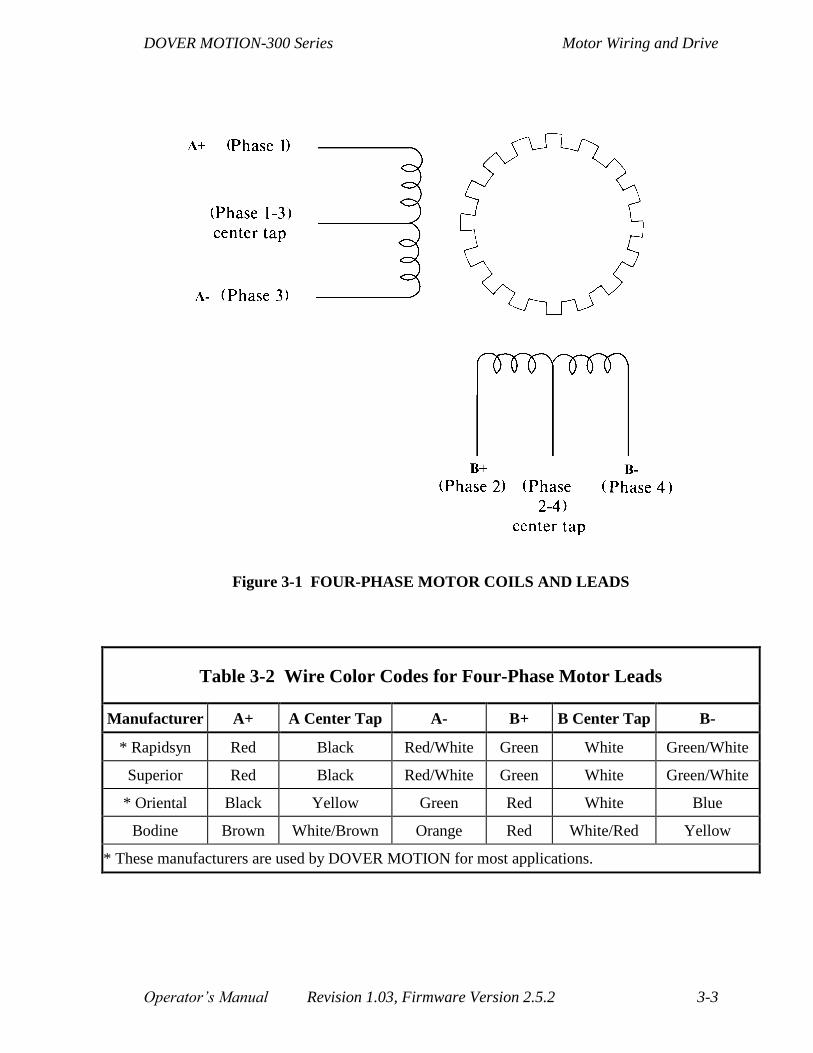
DOVER MOTION-300 Series Motor Wiring and Drive
Operator’s Manual Revision 1.03, Firmware Version 2.5.2 3-3
Figure 3-1 FOUR-PHASE MOTOR COILS AND LEADS
Table 3-2 Wire Color Codes for Four-Phase Motor Leads
Manufacturer A+ A Center Tap A- B+ B Center Tap B-
* Rapidsyn Red Black Red/White Green White Green/White
Superior Red Black Red/White Green White Green/White
* Oriental Black Yellow Green Red White Blue
Bodine Brown White/Brown Orange Red White/Red Yellow
* These manufacturers are used by DOVER MOTION for most applications.
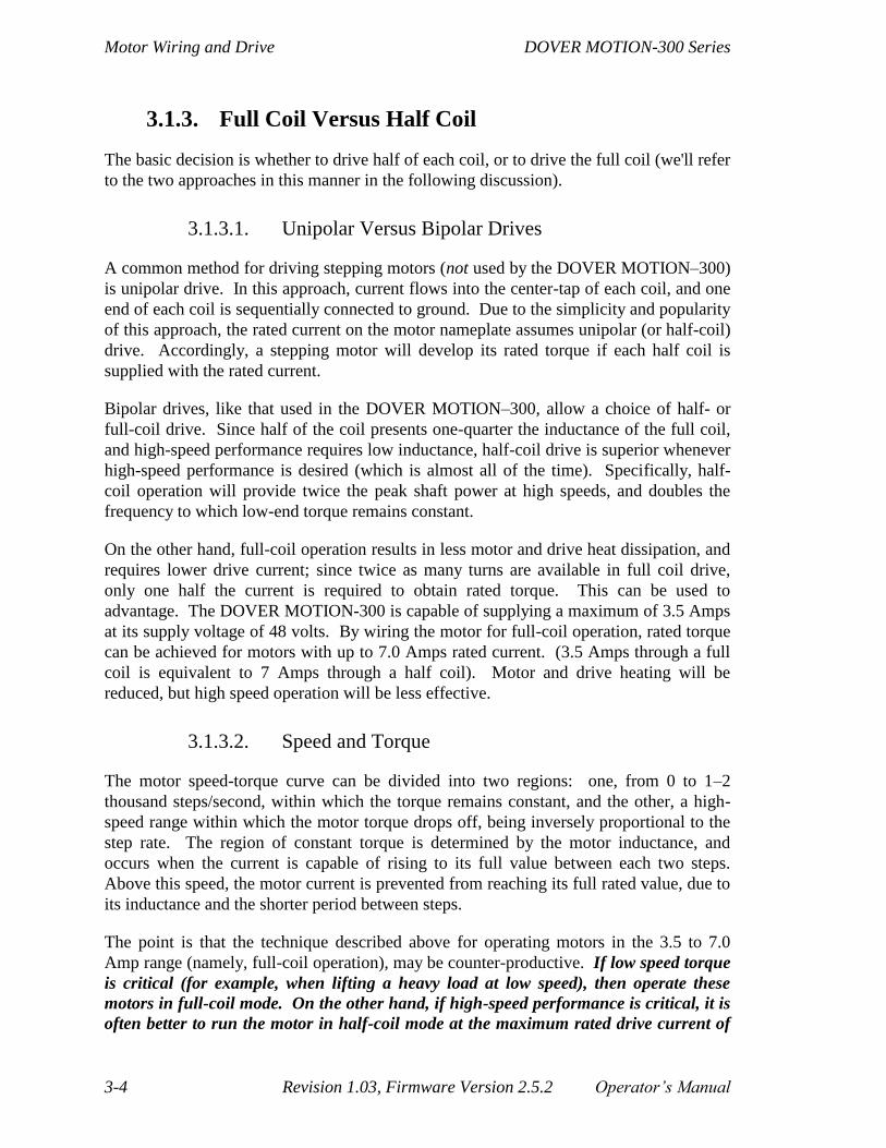
Motor Wiring and Drive DOVER MOTION-300 Series
3-4 Revision 1.03, Firmware Version 2.5.2 Operator’s Manual
3.1.3. Full Coil Versus Half Coil
The basic decision is whether to drive half of each coil, or to drive the full coil (we'll refer
to the two approaches in this manner in the following discussion).
3.1.3.1. Unipolar Versus Bipolar Drives
A common method for driving stepping motors (not used by the DOVER MOTION–300)
is unipolar drive. In this approach, current flows into the center-tap of each coil, and one
end of each coil is sequentially connected to ground. Due to the simplicity and popularity
of this approach, the rated current on the motor nameplate assumes unipolar (or half-coil)
drive. Accordingly, a stepping motor will develop its rated torque if each half coil is
supplied with the rated current.
Bipolar drives, like that used in the DOVER MOTION–300, allow a choice of half- or
full-coil drive. Since half of the coil presents one-quarter the inductance of the full coil,
and high-speed performance requires low inductance, half-coil drive is superior whenever
high-speed performance is desired (which is almost all of the time). Specifically, half-
coil operation will provide twice the peak shaft power at high speeds, and doubles the
frequency to which low-end torque remains constant.
On the other hand, full-coil operation results in less motor and drive heat dissipation, and
requires lower drive current; since twice as many turns are available in full coil drive,
only one half the current is required to obtain rated torque. This can be used to
advantage. The DOVER MOTION-300 is capable of supplying a maximum of 3.5 Amps
at its supply voltage of 48 volts. By wiring the motor for full-coil operation, rated torque
can be achieved for motors with up to 7.0 Amps rated current. (3.5 Amps through a full
coil is equivalent to 7 Amps through a half coil). Motor and drive heating will be
reduced, but high speed operation will be less effective.
3.1.3.2. Speed and Torque
The motor speed-torque curve can be divided into two regions: one, from 0 to 1–2
thousand steps/second, within which the torque remains constant, and the other, a high-
speed range within which the motor torque drops off, being inversely proportional to the
step rate. The region of constant torque is determined by the motor inductance, and
occurs when the current is capable of rising to its full value between each two steps.
Above this speed, the motor current is prevented from reaching its full rated value, due to
its inductance and the shorter period between steps.
The point is that the technique described above for operating motors in the 3.5 to 7.0
Amp range (namely, full-coil operation), may be counter-productive. If low speed torque
is critical (for example, when lifting a heavy load at low speed), then operate these
motors in full-coil mode. On the other hand, if high-speed performance is critical, it is
often better to run the motor in half-coil mode at the maximum rated drive current of

DOVER MOTION-300 Series Motor Wiring and Drive
Operator’s Manual Revision 1.03, Firmware Version 2.5.2 3-5
3.5 Amps. Low-speed torque will be reduced, but operation at high speeds will be greatly
enhanced by the four-fold reduction in inductance. In this region, motor torque is
unaffected by the current setting, since the brief period between steps never lets the motor
reach its rated current. In this region, performance is dictated solely by the drive voltage
(a relatively high 54 volts) and the motor inductance.
3.1.4. 8-Wire and 4-Wire Motors
In addition to six-lead motors, a small percentage are available as either 8-wire or 4-wire
types. In the case of a four-wire motor, there is no center-tap; accordingly, full coil
operation is the only choice. On the other hand, the motor's rated current will reflect the
actual, as opposed to half-coil, value. (Thus, to calculate the appropriate Main Current
Resistance as explained in Section 3.3, you would match the rated current of the motor
with a corresponding resistance in the half-coil column of Table 3-3. For example a four-
lead motor rated at 2 Amps will use a 68K resistor.)
Eight lead motors bring out both ends of each half of each coil. The motor can therefore
be wired as a full coil (by placing each half in series); as a half coil (by operating only one
half of each coil); or in a third fashion: by placing the two half coils in parallel. In this
latter case, the inductance remains unchanged, but the ohmic losses are halved; this
generally results in a 4 - 5% performance increase.
If the fact that paralleling the coil halves leaves the inductance unchanged
seems incorrect, recall that the coil halves share the same magnetic field; an
analogy is a coil wound with stranded wire; clearly, the inductance is not
proportional to the number of strands.
3.1.5. Midrange Resonance Suppression
In addition to providing a high-performance, bipolar chopper drive, the DOVER
MOTION–300 drive section includes the following features: efficient, FET output
drivers; programmable full and half step operation; opto-isolation from the CPU and
logic; and effective compensation for mid-range instability. This last feature is missing
from many other stepping motor drives, both low-end and otherwise full featured units,
and can often make or break an application. Mid-range instability is a resonant condition
that may occur between 5 and 15 revolutions per second (1000-3000 full steps/second).
The instability is endemic to stepping motors driving actual loads, and does not occur due
to a defect in drive design. We would argue, however, that a failure to take appropriate
counter measures to this fact of life is, in itself, a design flaw. Unlike the fundamental
motor resonance at ~80 steps/second, operation in half step mode or micro stepping will
not make it go away. Depending on specific aspects of the load, this resonance may or
may not rear its head in any given application. It is characterized by an oscillation of the
stepping motor from its intended position, typically at about 50-100 Hz, which slowly
builds in amplitude over many cycles (frequently causing a stall condition within a second
of its onset).

Motor Wiring and Drive DOVER MOTION-300 Series
3-6 Revision 1.03, Firmware Version 2.5.2 Operator’s Manual
The DOVER MOTION–300 does away with mid-range instability via circuitry that
senses the onset of mid-range instability and introduces the electronic equivalent of
viscous damping to eliminate the problem. As a result, all motor torque is available to
accelerate the load, instead of being wasted on useless oscillations. This circuit retains
maximum damping of parasitic oscillations during acceleration and deceleration phases,
as well as while running at constant speed. Bizarre mechanical corrective measures, such
as Lancester dampers, dash pots, and ultra-viscous lubricants are accordingly
unnecessary.
3.2. The DOVER MOTION Motor Connection
You might conclude from Section 3.1 that a six-lead motor would work somewhat better
by connecting the two coil ends together, thereby paralleling them, and running the
DOVER MOTION–300 between the center-tap and both ends. However, the "bifiliar"
winding technique needed for proper unipolar operation results in the coils' fields
opposing each other in this configuration, resulting in very poor performance.
The actual connection of the motor to the DOVER MOTION–300 occurs via the rear
panel Motor connector. This is a DE–9S, socket type (to prevent inadvertent short
circuits between exposed pins), D submini connector. The connector orientation and pin-
out are shown in Figure 3-2.
Mating connectors are widely available from most electronics distributors.
If the DOVER MOTION-300 will be connected to a DOVER MOTION
positioning stage, we recommend the use of our standard motor cables, which are
shielded, strain-relieved, and feature EMI-shielded die-cast connector shells with
locking jackscrews.
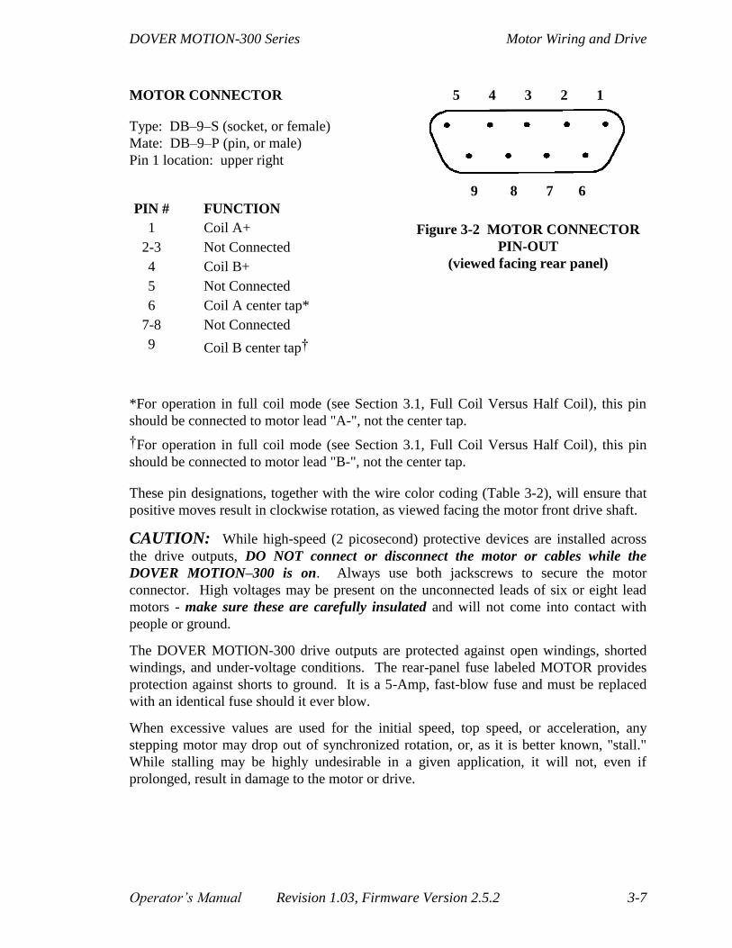
DOVER MOTION-300 Series Motor Wiring and Drive
Operator’s Manual Revision 1.03, Firmware Version 2.5.2 3-7
MOTOR CONNECTOR
Type: DB–9–S (socket, or female)
Mate: DB–9–P (pin, or male)
Pin 1 location: upper right
PIN # FUNCTION
1 Coil A+
2-3 Not Connected
4 Coil B+
5 Not Connected
6 Coil A center tap*
7-8 Not Connected
9 Coil B center tap†
5 4 3 2 1
9 8 7 6
Figure 3-2 MOTOR CONNECTOR
PIN-OUT
(viewed facing rear panel)
*For operation in full coil mode (see Section 3.1, Full Coil Versus Half Coil), this pin
should be connected to motor lead "A-", not the center tap.
†For operation in full coil mode (see Section 3.1, Full Coil Versus Half Coil), this pin
should be connected to motor lead "B-", not the center tap.
These pin designations, together with the wire color coding (Table 3-2), will ensure that
positive moves result in clockwise rotation, as viewed facing the motor front drive shaft.
CAUTION: While high-speed (2 picosecond) protective devices are installed across
the drive outputs, DO NOT connect or disconnect the motor or cables while the
DOVER MOTION–300 is on. Always use both jackscrews to secure the motor
connector. High voltages may be present on the unconnected leads of six or eight lead
motors - make sure these are carefully insulated and will not come into contact with
people or ground.
The DOVER MOTION-300 drive outputs are protected against open windings, shorted
windings, and under-voltage conditions. The rear-panel fuse labeled MOTOR provides
protection against shorts to ground. It is a 5-Amp, fast-blow fuse and must be replaced
with an identical fuse should it ever blow.
When excessive values are used for the initial speed, top speed, or acceleration, any
stepping motor may drop out of synchronized rotation, or, as it is better known, "stall."
While stalling may be highly undesirable in a given application, it will not, even if
prolonged, result in damage to the motor or drive.

Motor Wiring and Drive DOVER MOTION-300 Series
3-8 Revision 1.03, Firmware Version 2.5.2 Operator’s Manual
3.3. Current Setting
3.3.1. Main Current and Reduced Idle Current
There are (potentially) two different levels of current from the DOVER MOTION–300
Series controller to the stepping motors:
Main Current—delivered either at all times or just during and shortly after moves;
Reduced Idle Current—delivered either not at all or between moves.
The Reduced Idle Current option, which allows the current to drop between moves, is
activated as shipped, and can be deactivated with the Idle Current commands (under
Motor Current Commands in Section 6.3). This can be done on a per-axis basis. The
levels of the Main Current and Reduced Idle Current are also set separately for each axis.
Here we will see how to determine what these levels should be and how to set them.
It is important that the Main Current match the requirements of the particular motors
employed. Usually, the DOVER MOTION–300 will have been pre-set correctly for your
stepping motors at the factory, particularly if they are DOVER MOTION stepping motors
that you purchased along with the controller. However, occasions may arise when you
will need to change the settings.
In addition, you may need to change the level of Reduced Idle Current based on the
degree of torque the motors must maintain between moves for the applications you are
running.
The Main Current and Reduced Idle Current are set indirectly, by setting the Main
Current Resistance and the Reduced Current Set Resistance through a set of dip-switches.
3.3.2. Current and Resistance
As we said, it is important that the Main Current match the requirements of the motor.
This is done by setting an appropriate value for the Main Current Resistance. In other
words, the resistance determines the current (but not in the simple relationship of Ohm’s
law—in this case, the current rises with the resistance). Table 3-3 shows the appropriate
Main Current Resistance settings for various current ratings, with specific reference to the
DOVER MOTION MDM7 and SDM7 high-performance stepping-motor drive modules.
The appropriate setting is different for half-coil and full-coil operation.

DOVER MOTION-300 Series Motor Wiring and Drive
Operator’s Manual Revision 1.03, Firmware Version 2.5.2 3-9
Table 3-3 Main Current Resistance Settings for
MDM7 And SDM7 Drive Modules
Rated Motor Current
(six-lead unipolar convention)
Main Current Resistance Setting
(5%, ¼ watt)
Half-Coil Drive Full-Coil Drive
0.75 Amps 12K ohms
1.00 Amps 15K ohms
1.25 Amps 27K ohms
1.50 Amps 33K ohms 12K ohms
1.75 Amps 47K ohms 13K ohms
2.00 Amps 68K ohms 15K ohms
2.25 Amps 82K ohms 22K ohms
2.50 Amps 120K ohms 27K ohms
2.75 Amps 180K ohms 30K ohms
3.00 Amps 270K ohms 33K ohms
3.25 Amps 560K ohms 39K ohms
3.50 Amps 3.3M ohms 47K ohms
4.00 Amps 68K ohms
4.50 Amps 82K ohms
5.00 Amps 120K ohms
5.50 Amps 180K ohms
6.00 Amps 270K ohms
6.50 Amps 560K ohms
7.00 Amps 3.3M ohms
Unless otherwise specified, or factory pre-set to match a DOVER MOTION positioning
stage, we ship DOVER MOTION-300 units with the resistance set to provide 1.0 Amps
Main Current and 0.75 Amp Reduced Idle Current.

Motor Wiring and Drive DOVER MOTION-300 Series
3-10 Revision 1.03, Firmware Version 2.5.2 Operator’s Manual
3.3.3. Calculating the Main Current Dip-Switch Setting
To determine the dip-switch setting for the Main Current:
1. Find the current-per-phase rating (“CPPR”—shown in Table 3-1, column 6, for
DOVER MOTION stepping motors).
2. In Table 3-3, column 1, find the current value closest to the current per phase rating.
3. In Table 3-3, column 2 (for half-coil operation—or column 3 for full-coil operation),
find the resistance—Main Current Resistance (“MCR”)—corresponding to that
current value.
4. In Table 3-4, find the dip-switch setting (for switch positions 1-6) for that resistance.
Of the 10 dip-switches, the settings of the first 6 determine the Main Current
Resistance. Each adds or removes a resistor of a given value (560K, 270K,
120K, 68K, 33K or 15K ohms, respectively, for switches 1 through 6) from a
set of resistors arrayed in parallel. The UP position of a switch is OFF,
represented by ‘0’, and removes its resistor from the array. The DOWN
position is ON, represented by ‘1’, and adds the resistor to the array. The
Main Current Resistance is determined from the six switch settings (S1, S2,
etc.) as follows:
MCR = 1000/(S1/560 + S2/270 + S3/120 + S4/68 + S5/33 + S6/15)

DOVER MOTION-300 Series Motor Wiring and Drive
Operator’s Manual Revision 1.03, Firmware Version 2.5.2 3-11
Table 3-4 Dip-Switch Settings for Main Current Resistance
1 2 3 4 5 6 Switch # 1 2 3 4 5 6
Resistance Resistance
0 0 0 0 0 0 0 0 0 0 0 1 15.0K ohms
1 0 0 0 0 0 560K ohms 1 0 0 0 0 1 14.6K ohms
0 1 0 0 0 0 270K ohms 0 1 0 0 0 1 14.2K ohms
1 1 0 0 0 0 182K ohms 1 1 0 0 0 1 13.9K ohms
0 0 1 0 0 0 120K ohms 0 0 1 0 0 1 13.3K ohms
1 0 1 0 0 0 99K ohms 1 0 1 0 0 1 13.0K ohms
0 1 1 0 0 0 83K ohms 0 1 1 0 0 1 12.7K ohms
1 1 1 0 0 0 72K ohms 1 1 1 0 0 1 12.4K ohms
0 0 0 1 0 0 68K ohms 0 0 0 1 0 1 12.3K ohms
1 0 0 1 0 0 61K ohms 1 0 0 1 0 1 12.0K ohms
0 1 0 1 0 0 54K ohms 0 1 0 1 0 1 11.8K ohms
1 1 0 1 0 0 50K ohms 1 1 0 1 0 1 11.5K ohms
0 0 1 1 0 0 43K ohms 0 0 1 1 0 1 11.1K ohms
1 0 1 1 0 0 40K ohms 1 0 1 1 0 1 10.9K ohms
0 1 1 1 0 0 37K ohms 0 1 1 1 0 1 10.7K ohms
1 1 1 1 0 0 35K ohms 1 1 1 1 0 1 10.5K ohms
0 0 0 0 1 0 33K ohms 0 0 0 0 1 1 10.3K ohms
1 0 0 0 1 0 31K ohms 1 0 0 0 1 1 10.1K ohms
0 1 0 0 1 0 29K ohms 0 1 0 0 1 1 9.9K ohms
1 1 0 0 1 0 28K ohms 1 1 0 0 1 1 9.8K ohms
0 0 1 0 1 0 26K ohms 0 0 1 0 1 1 9.5K ohms
1 0 1 0 1 0 25K ohms 1 0 1 0 1 1 9.3K ohms
0 1 1 0 1 0 24K ohms 0 1 1 0 1 1 9.2K ohms
1 1 1 0 1 0 23K ohms 1 1 1 0 1 1 9.0K ohms
0 0 0 1 1 0 22K ohms 0 0 0 1 1 1 9.0K ohms
1 0 0 1 1 0 21K ohms 1 0 0 1 1 1 8.8K ohms
0 1 0 1 1 0 21K ohms 0 1 0 1 1 1 8.7K ohms
1 1 0 1 1 0 20K ohms 1 1 0 1 1 1 8.5K ohms
0 0 1 1 1 0 18.7K ohms 0 0 1 1 1 1 8.3K ohms
1 0 1 1 1 0 18.1K ohms 1 0 1 1 1 1 8.2K ohms
0 1 1 1 1 0 17.5K ohms 0 1 1 1 1 1 8.1K ohms
1 1 1 1 1 0 17.0K ohms 1 1 1 1 1 1 8.0K ohms

Motor Wiring and Drive DOVER MOTION-300 Series
3-12 Revision 1.03, Firmware Version 2.5.2 Operator’s Manual
3.3.4. Calculating the Reduced Current
Set Resistance Setting
To determine the dip-switch setting for the Reduced Idle Current:
1. Find the Torque Rating (“TR”—shown in Table 3-1, column 4, for DOVER
MOTION stepping motors).
2. Decide what torque would be adequate for the motor between moves (while receiving
Reduced Idle Current)—this is the Reduced Idle Current Torque (“RICT”).
3. Calculate the Reduced Idle Current (“RIC”): multiply the Current-per-Phase Rating
by the torque rating, then divide by the Reduced Idle Current Torque:
RIC = (CPPR*TR)/(RICT)
4. Calculate the Reduced Current Set Resistance (“RCSR”): Refer to Table 3-3 to select
the resistance that corresponds to the Reduced Idle Current calculated in step 3. This
is the Reduced Idle Current Resistance (“RICR”). Multiply the Reduced Idle Current
Resistance by the Main Current Resistance, then divide by the difference between the
Main Current Resistance and the Reduced Idle Current Resistance:
RICR)(MCR
)(RICR)(MCRRCSR
The Reduced Current Set Resistance (“RCSR”) is different from the Reduced
Idle Current Resistance (RCSR RICR) because dip-switches 7-10 control an
additional four resistors (270k, 120k, 68k, and 33K ohms, respectively, for
switches 7 through 10). These are added to or removed from a separate
parallel array. The resulting resistance (RCSR) is placed in parallel with the
Main Current Resistance (MCR) and it is that combined resistance which is
the Reduced Idle Current Resistance (RICR).
5. The appropriate Reduced Idle Current resistance can be calculated from the desired
torque. If the specified resistor value results in a motor temperature that is too high
for a given application, use of a lower value resistor will decrease low-end torque
while leaving high speed operation unaffected.
6. Read the dip-switch settings for the Reduced Current Set Resistance from Table 3-5.
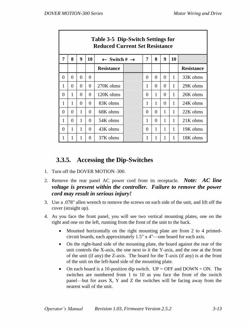
DOVER MOTION-300 Series Motor Wiring and Drive
Operator’s Manual Revision 1.03, Firmware Version 2.5.2 3-13
Table 3-5 Dip-Switch Settings for
Reduced Current Set Resistance
7 8 9 10 Switch # 7 8 9 10
Resistance Resistance
0 0 0 0 0 0 0 1 33K ohms
1 0 0 0 270K ohms 1 0 0 1 29K ohms
0 1 0 0 120K ohms 0 1 0 1 26K ohms
1 1 0 0 83K ohms 1 1 0 1 24K ohms
0 0 1 0 68K ohms 0 0 1 1 22K ohms
1 0 1 0 54K ohms 1 0 1 1 21K ohms
0 1 1 0 43K ohms 0 1 1 1 19K ohms
1 1 1 0 37K ohms 1 1 1 1 18K ohms
3.3.5. Accessing the Dip-Switches
1. Turn off the DOVER MOTION–300.
2. Remove the rear panel AC power cord from its receptacle. Note: AC line
voltage is present within the controller. Failure to remove the power
cord may result in serious injury!
3. Use a .078" allen wrench to remove the screws on each side of the unit, and lift off the
cover (straight up).
4. As you face the front panel, you will see two vertical mounting plates, one on the
right and one on the left, running from the front of the unit to the back.
Mounted horizontally on the right mounting plate are from 2 to 4 printed-
circuit boards, each approximately 1.5" x 4"—one board for each axis.
On the right-hand side of the mounting plate, the board against the rear of the
unit controls the X-axis, the one next to it the Y-axis, and the one at the front
of the unit (if any) the Z-axis. The board for the T-axis (if any) is at the front
of the unit on the left-hand side of the mounting plate.
On each board is a 10-position dip switch. UP = OFF and DOWN = ON. The
switches are numbered from 1 to 10 as you face the front of the switch
panel—but for axes X, Y and Z the switches will be facing away from the
nearest wall of the unit.

Motor Wiring and Drive DOVER MOTION-300 Series
3-14 Revision 1.03, Firmware Version 2.5.2 Operator’s Manual
5. Set switches 1 to 6 as determined in Calculating the Main Current Dip-Switch Setting
(Section 3.3.3).
6. Set switches 7 to 10 as determined in Calculating the Reduced Current Set Resistance
Setting (Section 3.3.4).
7. Replace the top cover and the screws.
8. Replace the AC power cord.

DOVER MOTION-300 Series The Front Panel
Operator’s Manual Revision 1.03, Firmware Version 2.5.2 4-1
4. The Front Panel
While it appears quite simple (and it is), the front panel encodes a variety of functions
through the following controls:
A rocker switch labeled ON/OFF, located in the lower left-hand corner, controls AC
power;
Two momentary push buttons labeled START and STOP have both obvious and
specialized functions;
A pair of decade switches or “thumbwheels” labeled PROGRAM SELECT can be set
to values ‘00’ - ‘99' and are decremented or incremented by depressing the small
button above or below the numeric display window.
4.1. Baud Rate Selection
The factory-set default baud rate is set at 9600, which is reasonably fast, commonly
available, and matches the DOVER MOTION terminal emulator. If your terminal or
computer requires a lower baud rate, or allows use of the faster baud rates (up to a
blistering 115,200!), then the thumbwheels can be used to program the DOVER
MOTION-300 accordingly.
The procedure described here changes the default baud rate, so that subsequent power-
ups will automatically load the new values. (However, Master Reset (Section 4.7) will
return the default baud rate to the factory-set default.) This new default baud rate and
word format can be altered at any power-up by repeating the process. (It can also be
altered by the Baud RaTe command, under Communication Configuration Commands in
Section 7.3).
If a communications port other than the primary serial communications port
(com 1) has been operative prior to performing this precedure, this procedure
will also switch communications to the primary serial port.
The brief interval during power-up is unique (or after RESET—see under Default
Commands in Section 7.3), and the START, STOP, and PROGRAM SELECT switches
have specific functions during this period. If the START button is depressed before
turning on AC power and held down until at least one second after, and the number in
the thumbwheels is between 40 and 59, then the thumbwheel setting determines the
baud rate of the RS-232 serial port. The mapping of thumbwheel setting to baud rate
depends on the parity and word-length setting of your computer (see Table 4-1).

The Front Panel DOVER MOTION-300 Series
4-2 Revision 1.03, Firmware Version 2.5.2 Operator’s Manual
Table 4-1 Baud Rate Selection
BAUD RATE THUMBWHEEL SETTING
No Parity,
8 Bits/Word*
1 Stop Bit
Even Parity
Enabled,
7 Bits/Word†
1 Stop Bit
9600 40‡ 50
19,200 41 51
38,400 42 52
57,600 43 53
115,200 44 54
1200 45 55
2400 46 56
4800 47 57
230,000 48‡ 58
1,152,000 49 59
* This is the most common setting.
† This is the most popular alternative setting.
‡ This is the factory-set default.

DOVER MOTION-300 Series The Front Panel
Operator’s Manual Revision 1.03, Firmware Version 2.5.2 4-3
4.2. Handshaking
Handshaking helps ensure smooth communication between the DOVER MOTION-300
controller and a PC or terminal, by preventing either device from sending signals faster
than the other can process them. Data from the sending device flows into a buffer in the
receiving device. If the receiving device cannot process the data fast enough, the buffer
could “overflow,” causing data loss and consequent errors. With handshaking, the
receiving device monitors its buffer level and, when the buffer is approaching overflow,
sends a signal to the sending device to stop sending more data. When the buffer level is
lower, the receiving device sends a signal telling the sending device to resume sending
data.
The DOVER MOTION-300 supports both hardware and software handshaking, and also
has a circuit to prevent communication from getting “hung” with devices that expect
DTR/DSR handshaking. Since this circuit is activated automatically when you use a 25-
pin serial cable, you will probably not need to concern yourself with DTR/DSR
handshaking.
4.2.1. Hardware and Software Handshaking
You can implement either hardware or software handshaking—or both, or neither. Each
requires appropriate settings on both the DOVER MOTION-300 and the PC or terminal.
In addition, hardware handshaking requires that pins 4 and 5 on the DOVER MOTION-
300 Serial Port be connected (which would happen automatically with a 25-wire cable, as
recommended).
In hardware handshaking, when the DOVER MOTION-300 data-receiving buffer
approaches overflow, the voltage in the CTS wire (pin 5) is changed from +5 Volts to –5
Volts, telling the PC or terminal to stop sending data. When the buffer is less full, the
voltage is changed back, and data transmission is resumed. The PC or terminal signals
the DOVER MOTION-300 the same way on the RTS wire (pin 4). Hardware
handshaking has the advantage of a direct dedicated line between the two devices that is
independent of the data channel.
In software handshaking, when the DOVER MOTION-300 data-receiving buffer
approaches overflow, a Ctrl+S character (ASCII dec 19, hex 13H) is sent to the PC or
terminal on the RxD data wire (pin 3), telling it to stop sending data. When the buffer is
less full, a Ctrl+Q character (ASCII dec 17, hex 11H) is sent, and data transmission is
resumed. The PC or terminal signals the DOVER MOTION-300 the same way on the
TxD data wire (pin 2). Software handshaking has the advantage that the Ctrl+S and
Ctrl+Q characters can be sent to the DOVER MOTION manually from the keyboard in
order to pause and resume processes such as the fast scrolling of a long program listing.
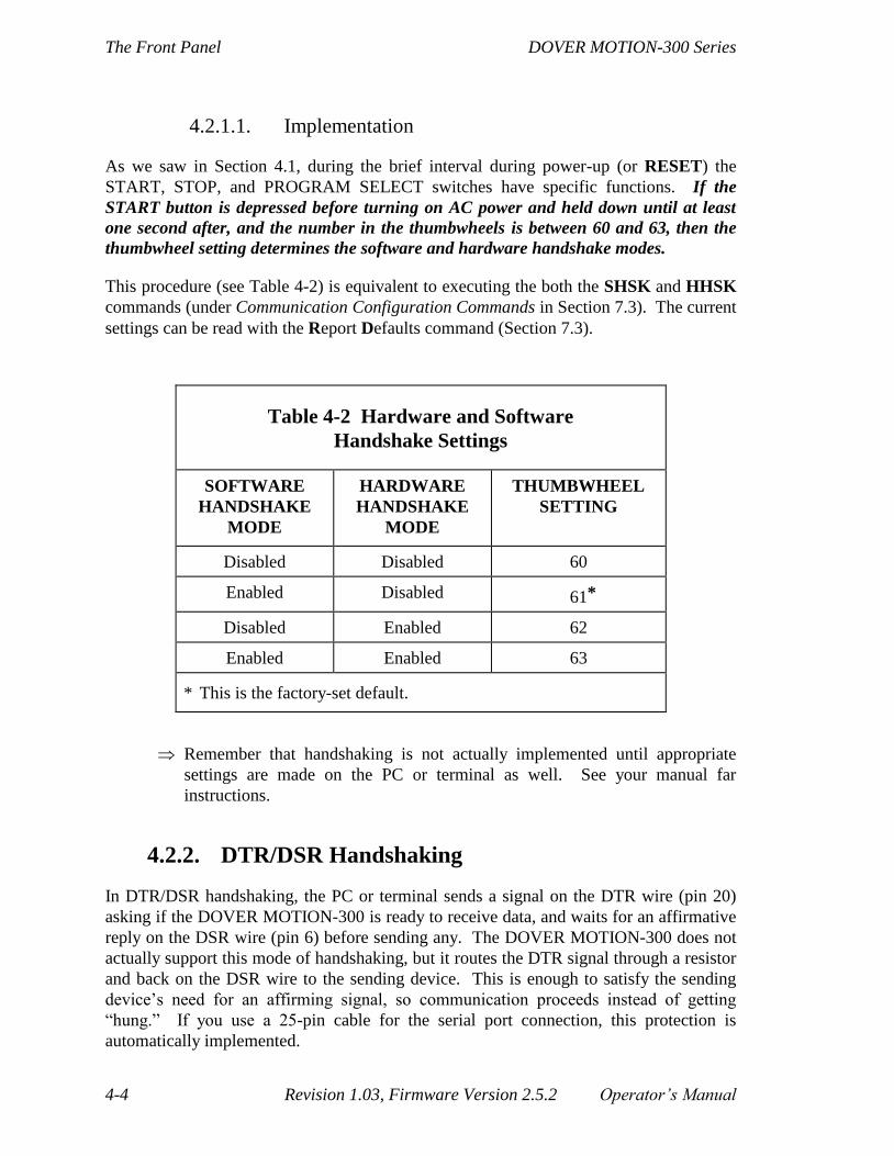
The Front Panel DOVER MOTION-300 Series
4-4 Revision 1.03, Firmware Version 2.5.2 Operator’s Manual
4.2.1.1. Implementation
As we saw in Section 4.1, during the brief interval during power-up (or RESET) the
START, STOP, and PROGRAM SELECT switches have specific functions. If the
START button is depressed before turning on AC power and held down until at least
one second after, and the number in the thumbwheels is between 60 and 63, then the
thumbwheel setting determines the software and hardware handshake modes.
This procedure (see Table 4-2) is equivalent to executing the both the SHSK and HHSK
commands (under Communication Configuration Commands in Section 7.3). The current
settings can be read with the Report Defaults command (Section 7.3).
Table 4-2 Hardware and Software
Handshake Settings
SOFTWARE
HANDSHAKE
MODE
HARDWARE
HANDSHAKE
MODE
THUMBWHEEL
SETTING
Disabled Disabled 60
Enabled Disabled 61*
Disabled Enabled 62
Enabled Enabled 63
* This is the factory-set default.
Remember that handshaking is not actually implemented until appropriate
settings are made on the PC or terminal as well. See your manual far
instructions.
4.2.2. DTR/DSR Handshaking
In DTR/DSR handshaking, the PC or terminal sends a signal on the DTR wire (pin 20)
asking if the DOVER MOTION-300 is ready to receive data, and waits for an affirmative
reply on the DSR wire (pin 6) before sending any. The DOVER MOTION-300 does not
actually support this mode of handshaking, but it routes the DTR signal through a resistor
and back on the DSR wire to the sending device. This is enough to satisfy the sending
device’s need for an affirming signal, so communication proceeds instead of getting
“hung.” If you use a 25-pin cable for the serial port connection, this protection is
automatically implemented.
DOVER MOTION-300 Series The Front Panel
Operator’s Manual Revision 1.03, Firmware Version 2.5.2 4-5
4.3. Program Select
One second after power-up, the functions of the START and STOP buttons and
PROGRAM SELECT thumbwheels change to match their labels.
As you create programs via the DOVER MOTION-300 editor, they are automatically
assigned program numbers (unlike the program names, which are user-assigned). The
program numbers begin at ‘01’ and are limited only by the available memory.
Program numbers ‘01’ to ‘89’ can be run by simply setting the desired program number
on the thumbwheels, and pressing the START switch. Program execution can be halted
by pressing the STOP button at any time, as well as by receipt of an ESCAPE character
(ASCII 27) over the serial communication port.
The above procedure limits front panel program execution to program numbers ‘01’ to
‘89’. However, any stored program can be executed with the Auto Run Program
command (under Default Commands in Section 7.3). With this command, any single
program can be set to auto-execute upon power-up. If the first command in the program
is a Wait for Start Button command (under Wait Commands in Section 7.3), then
execution will wait after power-up until the START switch is pressed. If you wish to run
a higher-numbered program repeatedly (or two or more programs in a repeating
sequence), initiated with the START button each time, you can do the following:
1. Write a new program that uses the eXecute Program command (see Execution
Commands in Section 7.3) to call the desired program(s);
2. Precede each program call with a Wait for Start Button command;
3. Place the Wait for Start/program call(s) in a subroutine that will run a specified
number of times, or in a JumP loop that will repeat indefinitely (see Program Flow
Commands in Section 7.3);
4. Run the new program using Auto Run Program;
5. Use the START button to initiate each run of the program(s) you wish to repeat.
4.4. Jog Functions
Thumbwheel-based selection of user programs is limited to numbers between 01 and 89.
The next six digits are reserved for jogging. When the thumbwheels are set between 90
and 98, the START and STOP buttons become the forward and reverse jog buttons for a
particular axis, as shown in Table 4-3.

The Front Panel DOVER MOTION-300 Series
4-6 Revision 1.03, Firmware Version 2.5.2 Operator’s Manual
Table 4-3 Thumbwheel Settings For Jogging
Axis Number* Common Name Thumbwheel Setting
0 X 90
1 Y 91
2 Z 92
3 T 93
4 U 94
5 V 95
6 R 96
7 S 97
8 P 98
* The axes are numbered ‘0’ to ‘8’, rather than ‘1’ to ‘9’,
because all operations that refer to them designate them
in this way—for example ‘A2’ selects the Z-axis.
To accommodate the need to provide fine (single-step) resolution, while still permitting
long moves, a three-tiered jog function has been implemented. By simply controlling the
duration of the switch closure, you can easily provide single steps, 20-step moves or
continuous motion.
Brief depressions of the START or STOP buttons result in the motor taking a single
step (forward or reverse, respectively).
If either button is held down slightly longer (one-quarter second), then a 20 step move
(actually 19 steps plus the initial jog step) is performed.
One-quarter second after the 20-step move is completed, a continuous move begins
and continues for as long as the button is held down.
In many cases (especially when you have purchased a complete system from DOVER
MOTION), the jog values for speed and acceleration will have been preset at DOVER
MOTION to reflect your specific application requirements and the chosen level of
microstepping in the stepping motor driver.
If the DOVER MOTION-300 unit was purchased separately, or if no customization of
values has been performed, then the firmware defaults will reflect divide-by-ten micro-
stepping. As shipped from the factory, the 20-step move will occur at a step rate of 4,000
steps/second. Continuous moves will begin at 4,000 steps/second (Jog Button Velocity

DOVER MOTION-300 Series The Front Panel
Operator’s Manual Revision 1.03, Firmware Version 2.5.2 4-7
Initial) and accelerate at 100,000 steps/second2 (Jog Button Acceleration) to a top speed
of 20,000 steps/second (Jog Button Velocity Final). Upon releasing the button, the motor
will decelerate at 100,000 steps/second2 to a stop.
These default values are appropriate for a wide range of typical loads, but if you are
employing a full-step drive (as opposed to a divide-by-ten microstep drive), then they are
too high and should be reduced by a factor of ten.
The relatively steep deceleration value (1,000,000 steps/second2) was chosen to minimize
overshoot upon releasing the button. The DOVER MOTION-300 is capable of producing
very high frequency pulse trains (up to 3,000,000 steps/second.) Should the Jog Button
Velocity Final command be used to attain high speeds, careful consideration of the
deceleration rate is in order. Too low a value will result in substantial overshoot upon
releasing a Jog button, possibly resulting in a crash through the limit switches at high
speed. A very high value of deceleration, curiously enough, may also result in overshoot,
as the stepping motor and load inertia may be unable to follow the pulse train, lose
synchronization and coast freely.
The default values may be overridden by use of the Jog Button Velocity Initial, Jog
Button Acceleration, and Jog Button Velocity Final commands (see Trajectory
Commands in Section 7.3). Once changed, the new values can be saved and restored
upon the next power-up by use of the Save Defaults command. (However, Master Reset
(Section 4.7) returns the default values to the factory-set defaults.)
4.5. Programmed Wait for Start
Another front panel function uses the START button. Whenever program execution
encounters a Wait for Start Button command, execution halts until the START button is
pressed. This allows certain program functions to wait until the operator wants to
proceed. The same function could, of course, be implemented via a conditional jump
command, using one of the rear panel digital I/O lines. However, a significant percentage
of applications need only a single “wait for switch” function, and this feature eliminates
any need to wire to the rear-panel connectors, provide a box for the switch, etc.
4.6. Master Reset
The START and STOP buttons can be used to clear the DOVER MOTION-300 program
memory and restore the factory-established values for default parameters, velocities, etc.
To perform this function, set the thumbwheels to “99”, and hold down both the STOP and
START buttons as the AC power is turned on. (If you forget to set the thumbwheels to
‘99’, you will receive an error message, “Initialization error (27): Unrecognized front
panel input detected”) Users are strongly encouraged to upload programs from the
DOVER MOTION-300 to a host computer (via the RS-232 or GPIB communications
ports) before using this feature, since there is no way of “undeleting” them.

The Front Panel DOVER MOTION-300 Series
4-8 Revision 1.03, Firmware Version 2.5.2 Operator’s Manual
4.7. GPIB Enable and Address
The STOP button can be used both to enable GPIB port communications and to set a
GPIB device address. The GPIB standard supports up to 31 device addresses. To enable
GPIB communications, simply set the thumbwheels to the desired GPIB address (from 0
to 30). Then, hold in the STOP button while turning on AC power and keep it depressed
for at least one second after. This will both set the GPIB address and enable GPIB
communications, and is the equivalent of executing the GADR Command followed by
CMDI 2 To switch to RS-232 serial communication, simply repeat the baud rate
initialization described in Section 4.1.
Once GPIB communication is enabled, this state and the device address are automatically
restored upon subsequent power-ups. See Section 6, and Communication Configuration
Commands in Section 7.3, for details on GPIB communications.
4.8. Selecting a Communications Port
Most commonly (and as shipped), the DOVER MOTION-300 will communicate with a
PC or terminal through serial port 1 (com 1), which may be the only port available on
your controller. However, serial port 2 (com 2) and/or a GPIB parallel port may also be
available.
You can select the port by thumbwheel, as shown in Table 4-4. Hold the STOP button
depressed during power-up with the thumbwheels set appropriately. If the controller is
connected to other devices through more than one port, the thumbwheel setting allows
you to change the port through which communication will actually occur.
The new setting becomes a default. The CoMmanD Input Port Select command (under
Communication Configuration Commands in Section 7.3) is equivalent to these
thumbwheel settings. Master Reset (Section 4.7) returns the setting to serial port 1
(com 1).

DOVER MOTION-300 Series The Front Panel
Operator’s Manual Revision 1.03, Firmware Version 2.5.2 4-9
Table 4-4 Communications Port Selection
COMMUNICATIONS
PORT
CMDI
PARAMETER
THUMBWHEEL
SETTING*
Com 1 (serial) 0 31†
Com 2 (serial) 1 32
GPIB (parallel) 2 33
* After setting thumbwheel, hold STOP button depressed during
power-up.
† This is the factory-set default.
If you select the GPIB port without having first configured the controller for GPIB
communication, on power-up communication will still be through your previous serial
port, but you will receive an error message, “Initialization error (52): Error initializing
GPIB port”. However, if you select serial port 2 (com 2, CMDI 1) when that port is not
configured, communication is transferred to the nonfunctional port. Then you must
power-up with thumbwheel setting ‘31’ and the STOP button depressed to restore
communication with the controller.

The Front Panel DOVER MOTION-300 Series
4-10 Revision 1.03, Firmware Version 2.5.2 Operator’s Manual

DOVER MOTION-300 Series Serial Communication
Operator’s Manual Revision 1.03, Firmware Version 2.5.2 5-1
5. Serial Communication
5.1. Serial Port Configuration
The DOVER MOTION-300’s RS-232 Serial Port provides the simplest means of
interfacing the unit to a host computer or terminal. Communicating with the DOVER
MOTION-300 consists of sending and receiving ASCII characters over the serial port.
This port is based on the NS16C552 UART chip, providing an advanced,
FIFO-buffered, high speed (to 1,152,000 baud!) serial interface.
The port is brought out on the rear panel DB-25P connector labeled: RS-232 SERIAL
(Figure 5-1). This connector is of the standard 25-pin D-submini type normally used for
serial ports; a mating six-foot serial cable is included with each DOVER MOTION-300.
This cable has socket type (female) DB-25 connectors at each end, allowing direct
connection to most terminals and computers.

Serial Communication DOVER MOTION-300 Series
5-2 Revision 1.03, Firmware Version 2.5.2 Operator’s Manual
(RS-232) SERIAL PORT CONNECTOR
Type: DB–25–P (pin, or male)
Mate: DB–25–S (socket, or female)
Pin 1 location: upper right
13 22 11 10 9 8 7 6 5 4 3 2 1
25 24 23 22 21 20 19 18 17 16 15 14
Figure 5-1 SERIAL PORT
CONNECTOR PIN-OUT
(viewed facing rear panel)
PIN # FUNCTION
1 PG — Protective Ground
2 TxD — data received by
DOVER MOTION-330
3 RxD — data driven by
DOVER MOTION-330
4 RTS — handshake received
by DOVER MOTION-330
(when enabled)
5 CTS — handshake driven
by DOVER MOTION-330
(when enabled)
6 DSR — connected to pin 20
(DTR) via 2.2K resistor
7 GND — logic ground
8 CD — Carrier detect
9 N.C.
10 N.C.
11 +5 Volts
12 N.C.
13 N.C.
14 N.C.
15 N.C.
16 N.C.
17 N.C.
18 N.C.
19 N.C.
20 DTR — connected to pin
6 (DSR) via 2.2K resistor
21 N.C.
22 N.C.
23 N.C.
24 N.C.
25 N.C.
The DOVER MOTION-300 supports several levels of the RS-232 standard. In the most
basic, a three-wire DCE serial port implementation, data is received on pin 2 (TX), and
transmitted on pin 3 (RX), while logic ground is present on pin 7.
While it may seem odd to label the receive line as “TX”, the DCE convention
defines the transmit line on the host computer (a DTE device) as the “TX”
line, and the nomenclature carries over to our required pin designations.

DOVER MOTION-300 Series Serial Communication
Operator’s Manual Revision 1.03, Firmware Version 2.5.2 5-3
The default (as shipped) baud rate of the DOVER MOTION-300 serial port is 9600, and data
will normally be transmitted with a 10-bit frame consisting of 1 start bit, 8 data bits, and 1 stop
bit (with no parity bit). The baud rate and word format can be changed as described in
Section 4.1.
The DOVER MOTION-300 serial port “echoes”, or retransmits all characters sent to it
(assuming it is assuming it is configured to echo characters—see “TERMinal Mode”
under Communication Configuration Commands in Section 7.3). While this is helpful in
providing a display on full-duplex terminals, it can also be used in another important
manner: if a host computer sending data to the DOVER MOTION-300 is appropriately
programmed, it can check each character as it comes back to compare it with the issued
character.
If a mismatch is detected (due, perhaps, to a missing or broken cable, defective
line drivers or receivers, a nearby arc welder, etc.), then the host can send a
command line terminator (ENTER in immediate mode, or CTRL+D while
editing a program) and try again. If several attempts are unsuccessful, the
operator can be alerted that communications have been disrupted.
But this is a slower, extra-safe way to communicate and generally unnecessary if you are
using one of the terminal modes designated as "good for computer I/O" in the discussion
of the TERMinal Mode command mentioned above, since these modes employ
automatic checks for the prompt and for errors.
The best way to familiarize yourself with the DOVER MOTION-300’s command set and
other functions is to use a terminal. To avoid unnecessary repetition, please refer to
Section 2 for details on using a terminal (or a PC running terminal emulation software) to
operate the DOVER MOTION-300. DOVER MOTION terminal emulator software is
supplied free with each DOVER MOTION-300.
5.2. PC Control
Previously, we explored the use of terminal emulation mode, where the programs were
both stored in and run from the DOVER MOTION-300, and the terminal (or computer in
terminal emulation mode) was used merely to communicate with the DOVER MOTION
controller. In the following discussion, we’ll explore the operation of the DOVER
MOTION-300 as an intelligent slave, under the control of a host computer. Here, even if
programs are still stored in and called up from the DOVER MOTION-300, the locus of
control shifts from the controller to the computer
5.2.1. Immediate versus Program Modes
A host computer can operate the DOVER MOTION-300 in either immediate or program
modes. In immediate mode, which is more common, the host has responsibility for

Serial Communication DOVER MOTION-300 Series
5-4 Revision 1.03, Firmware Version 2.5.2 Operator’s Manual
determining the sequence of events to be performed. The non-volatile memory of the
DOVER MOTION-300 is unused, as are the program-referenced commands such as JumP to
Label or Line # and Call Subroutine. The host computer issues a sequence of immediate
mode commands to the DOVER MOTION-300, and in the case of move commands, waits
until each command has been completed before sending the next one. Subroutines, loops,
waits, etc. are implemented in the host’s high level language program. Immediate mode is
discussed in more detail in Section 8.
In program mode, you can create and store motion sequences in the DOVER MOTION-
300’s own non-volatile memory. Programs are entered from the computer or terminal,
but upon exiting an edit (via ESCAPE), the program will be automatically stored and
assigned a program number for subsequent front panel thumbwheel execution, as well as
Auto Run operation. As many programs can be entered as the available memory will
allow. Program mode is discussed in more detail in Section 9.
5.2.2. Polling versus Interrupt Modes
Before providing sample programs, it is important to point out the two distinct modes by
which the host can determine when the DOVER MOTION-300 has completed a move.
Polling consists of the host repeatedly asking the DOVER MOTION-300 if the move
is complete by sending Report Status commands during the move (see “Report
Status” under Report Commands in Section 7.3). The Report Status command returns
an “M” if the move is still in process, and an “F” if the move is complete. Because of
the speed with which programs execute, thousands of Report Status requests may be
sent before the move is completed. This technique requires care in programming to
avoid overflowing input buffers, and it prevents the computer from performing any
other activities during the move.
In interrupt mode, the DOVER MOTION-300 sends an “F” (for finished) to the host
at the completion of each move. The host computer, after sending a Move command,
simply waits for the “F” before issuing another command. Interrupt mode is activated
by the Move Finished E[nable] command and deactivated by the Move Finished
D[isable] command (see “Move Finished” under Default Commands in Section 7.3).
As shipped, the Move Finished command defaults to the disabled state at power-up.
If the Save Defaults command is issued after enabling Move Finished, it will remain
enabled after each subsequent power-up.
The advantages of interrupt mode are simpler programming and freeing the host
computer from lengthy interrogation cycles.
Polling and interrupt mode are explored in the example programs given in the next
section.
DOVER MOTION-300 Series Serial Communication
Operator’s Manual Revision 1.03, Firmware Version 2.5.2 5-5
5.2.3. Example Programs
The following example programs are written in Microsoft QuickBasic, and are included
(in both source and executable versions) with several other programs on the DOVER
MOTION Help diskette shipped with each DOVER MOTION-300. To run any of the
programs on the diskette, install the programs on your computer as described in Section 2
and then type the example program’s name followed by the ENTER key—e.g., EX31
(ret).
These programs are not understood by the DOVER MOTION-300, but rather
by the host computer, and thus could have been written in any language the
computer would understand. However, the programs use the Microsoft
QuickBasic PRINT command to send commands to the DOVER MOTION-
300 in the DOVER MOTION-300’s own command language, and these
commands—plus the DOVER MOTION-300’s consequent actions and
responses back to the computer—are the only parts of the program that
actually involve the DOVER MOTION-300.
This is different from using a computer with the DOVER MOTION-300 in
program mode (Section 9), where programs in the computer are written in the
DOVER MOTION-300’s own command language and “speak” directly to the
DOVER MOTION-300 rather than to the computer itself.

Serial Communication DOVER MOTION-300 Series
5-6 Revision 1.03, Firmware Version 2.5.2 Operator’s Manual
5.2.3.1. EX31.BAS—Illustrates Move Finished
EX31.BAS is a simple program that enables Move Finished if it was not enabled already,
then moves a two-axis stepping motor XY-stage back and forth 1000 steps in each of the
two axes for 10 cycles.
The program begins with a number of ‘setup’ steps:
1. It recognizes that while the computer’s serial port for ‘talking’ with the DOVER
MOTION-300 is probably ‘com 1’, it also might be a different port, and so it gives
you the opportunity to change the port before the remainder of the program proceeds.
2. It then displays the title of the program, opens the computer’s com port in a simple
configuration, and displays that configuration.
3. Next, it configures the DOVER MOTION controller for terminal mode 3 (see
TERMinal Mode, under Communications Configurations Commands in Section 7.3),
so the controller will be sending to the computer only signals that are desirable for
this program.
4. Finally, it positions the cursor for printing pertinent information during the program.
At last, the program is ready to begin its real work.
The program then enables Move Finished. The “wait for ‘>’” guarantees that all echoed
and appended characters have been returned by the DOVER MOTION-300 before
continuing. A simple FOR-NEXT loop then sends appropriate commands out the serial
port, and calls a subroutine that waits until an “F” is returned before proceeding.
In closing, the program returns the DOVER MOTION controller to the default ‘Terminal
Mode 0’, then closes the computer’s com port.

DOVER MOTION-300 Series Serial Communication
Operator’s Manual Revision 1.03, Firmware Version 2.5.2 5-7
REM***************EX31.BAS...ILLUSTRATES TWO AXIS MOVE FINISHED*********
CLS 'CLEAR SCREEN
IF COMMAND$ = "2" THEN 'ALLOW USER TO CHANGE COM PORT ON THE FLY
comprt$ = COMMAND$
ELSE
comprt$ = "1" 'DEFAULT IS COM 1
END IF
LOCATE 10, 1
PRINT "***************EX31.BAS...ILLUSTRATES TWO AXIS MOVE FINISHED*********" OPEN "COM" + comprt$ + ":9600,N,8,1,RS,CS,DS,CD" FOR RANDOM AS #1 LEN = 5000'OPEN SERIAL PORT
LOCATE 11, 20 'DISPLAY COM PORT SETUP
PRINT "COM" + comprt$ + ":9600,N,8,1,RS,CS,DS,CD FOR RANDOM AS #1 LEN = 5000"
PRINT #1, "TERM 3" 'SETUP NO ECHO TERMINAL MODE
GOSUB WAIT.PROMPT 'WAIT UNTIL ">" PROMPT IS RETURNED
LOCATE 11, 1
PRINT SPACE$(80); 'CLEAR LINE
PRINT #1, "MFE" 'MAKE SURE MOVE FINISHED IS ENABLED
GOSUB WAIT.PROMPT 'AND WAIT FOR PROMPT
FOR I = 1 TO 10 'FOR-NEXT LOOP; 10 ITERATIONS
PRINT #1, "AA MR1000,1000" '+1000 STEP MOVE IN TWO AXES
GOSUB WAIT.STOPPED 'WAIT UNTIL MOTORS HAVE STOPPED
PRINT #1, "MR-1000,-1000" '-1000 STEP MOVE IN TWO AXES
GOSUB WAIT.STOPPED 'WAIT UNTIL MOTORS HAVE STOPPED
NEXT I 'AND REPEAT
PRINT #1, "TERM 0" 'RESTORE ECHO TERMINAL MODE
GOSUB WAIT.PROMPT 'AND WAIT FOR PROMPT
CLOSE 'CLOSE COM PORT
END 'END PROGRAM
WAIT.STOPPED: DO UNTIL INPUT$(1, #1) = "F" 'WAIT UNTIL AN "F" ARRIVES
LOOP 'LOOP PER ABOVE
RETURN 'EXIT SUBROUTINE
WAIT.PROMPT: DO UNTIL INPUT$(1, #1) = ">" 'WAIT UNTIL 3x0 READY (SENDS ">")
LOOP 'LOOP PER ABOVE
RETURN 'EXIT SUBROUTINE

Serial Communication DOVER MOTION-300 Series
5-8 Revision 1.03, Firmware Version 2.5.2 Operator’s Manual
While the foregoing example has the virtue of simplicity, it ties up the computer during
each move, because it waits in a loop for the “F” to return. Thus it is not a substantial
improvement over the polling mode, that ties up the computer by asking the DOVER
MOTION-300 continuously if the move is finished (See Polling versus Interrupt Modes,
above, and EX33.BAS below). At the expense of a slight overhead in program
complexity, the “F” may be used more efficiently to interrupt the calling routine, as
demonstrated in EX32.BAS below.
5.2.3.2. EX32.BAS—Illustrates Serial Interrupt Method
Using the returned “F” to interrupt the calling routine, as just discussed, is demonstrated
in the EX32.BAS, again in Microsoft QuickBasic. It achieves the calling routine
interrupt with ON COM(1) GOSUB and COM(1) ON, which are high-level (BASIC)
language implementations of a serial interrupt. Most languages should provide some
support to allow similar asynchronous, interrupt triggered subroutine calls. This relieves
the program of the need to continuously monitor the serial port.
The “setup” and “close-down” steps in this program are similar to those in
EX31.BAS
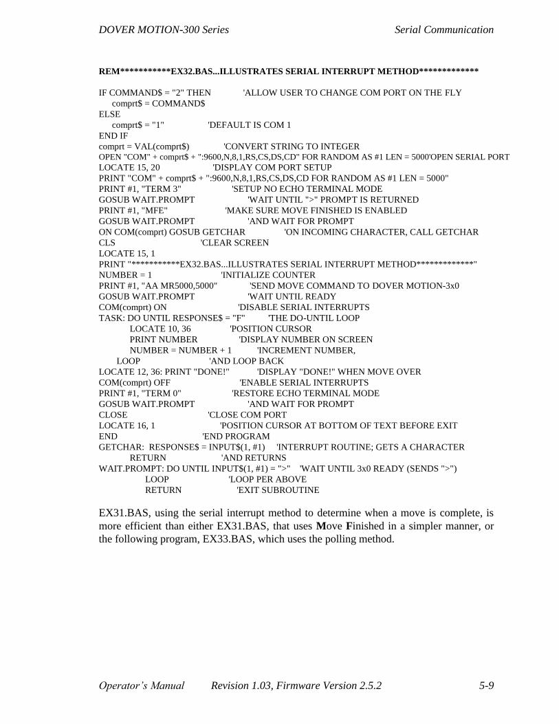
DOVER MOTION-300 Series Serial Communication
Operator’s Manual Revision 1.03, Firmware Version 2.5.2 5-9
REM***********EX32.BAS...ILLUSTRATES SERIAL INTERRUPT METHOD*************
IF COMMAND$ = "2" THEN 'ALLOW USER TO CHANGE COM PORT ON THE FLY
comprt$ = COMMAND$
ELSE
comprt$ = "1" 'DEFAULT IS COM 1
END IF
comprt = VAL(comprt$) 'CONVERT STRING TO INTEGER OPEN "COM" + comprt$ + ":9600,N,8,1,RS,CS,DS,CD" FOR RANDOM AS #1 LEN = 5000'OPEN SERIAL PORT
LOCATE 15, 20 'DISPLAY COM PORT SETUP
PRINT "COM" + comprt$ + ":9600,N,8,1,RS,CS,DS,CD FOR RANDOM AS #1 LEN = 5000"
PRINT #1, "TERM 3" 'SETUP NO ECHO TERMINAL MODE
GOSUB WAIT.PROMPT 'WAIT UNTIL ">" PROMPT IS RETURNED
PRINT #1, "MFE" 'MAKE SURE MOVE FINISHED IS ENABLED
GOSUB WAIT.PROMPT 'AND WAIT FOR PROMPT
ON COM(comprt) GOSUB GETCHAR 'ON INCOMING CHARACTER, CALL GETCHAR
CLS 'CLEAR SCREEN
LOCATE 15, 1
PRINT "***********EX32.BAS...ILLUSTRATES SERIAL INTERRUPT METHOD*************"
NUMBER = 1 'INITIALIZE COUNTER
PRINT #1, "AA MR5000,5000" 'SEND MOVE COMMAND TO DOVER MOTION-3x0
GOSUB WAIT.PROMPT 'WAIT UNTIL READY
COM(comprt) ON 'DISABLE SERIAL INTERRUPTS
TASK: DO UNTIL RESPONSE$ = "F" 'THE DO-UNTIL LOOP
LOCATE 10, 36 'POSITION CURSOR
PRINT NUMBER 'DISPLAY NUMBER ON SCREEN
NUMBER = NUMBER + 1 'INCREMENT NUMBER,
LOOP 'AND LOOP BACK
LOCATE 12, 36: PRINT "DONE!" 'DISPLAY "DONE!" WHEN MOVE OVER
COM(comprt) OFF 'ENABLE SERIAL INTERRUPTS
PRINT #1, "TERM 0" 'RESTORE ECHO TERMINAL MODE
GOSUB WAIT.PROMPT 'AND WAIT FOR PROMPT
CLOSE 'CLOSE COM PORT
LOCATE 16, 1 'POSITION CURSOR AT BOTTOM OF TEXT BEFORE EXIT
END 'END PROGRAM
GETCHAR: RESPONSE$ = INPUT$(1, #1) 'INTERRUPT ROUTINE; GETS A CHARACTER
RETURN 'AND RETURNS
WAIT.PROMPT: DO UNTIL INPUT$(1, #1) = ">" 'WAIT UNTIL 3x0 READY (SENDS ">")
LOOP 'LOOP PER ABOVE
RETURN 'EXIT SUBROUTINE
EX31.BAS, using the serial interrupt method to determine when a move is complete, is
more efficient than either EX31.BAS, that uses Move Finished in a simpler manner, or
the following program, EX33.BAS, which uses the polling method.

Serial Communication DOVER MOTION-300 Series
5-10 Revision 1.03, Firmware Version 2.5.2 Operator’s Manual
5.2.3.3. EX33.BAS—Illustrates Polling Mode
EX33.BAS illustrates the use of the polling with the Report Status command to
determine whether a move is complete. Instead of telling the DOVER MOTION-300 to
send an “F” when it is finished a move (Move Finished Enabled), then waiting for the
“F” to arrive, it repeatedly “polls” the DOVER MOTION-300 for the status of the move.
This method is even less efficient than that in EX31.BAS, but is included for the sake of
completeness.
The “setup” and “close-down” steps in this program are similar to those in
EX31.BAS

DOVER MOTION-300 Series Serial Communication
Operator’s Manual Revision 1.03, Firmware Version 2.5.2 5-11
REM***************EX33.BAS...ILLUSTRATES POLLING MODE*******************
IF COMMAND$ = "2" THEN 'ALLOW USER TO CHANGE COM PORT ON THE FLY
comprt$ = COMMAND$
ELSE
comprt$ = "1"
END IF
CLS
LOCATE 10, 1
PRINT "***************EX33.BAS...ILLUSTRATES POLLING MODE*******************" OPEN "COM" + comprt$ + ":9600,N,8,1,RS,CS,DS,CD" FOR RANDOM AS #1 LEN = 5000'OPEN SERIAL PORT
LOCATE 11, 20 'DISPLAY COM PORT SETUP
PRINT "COM" + comprt$ + ":9600,N,8,1,RS,CS,DS,CD FOR RANDOM AS #1 LEN = 5000"
PRINT #1, "TERM 3" 'SETUP NO ECHO TERMINAL MODE
GOSUB WAIT.PROMPT 'AND WAIT FOR PROMPT
LOCATE 11, 1
PRINT SPACE$(80); 'CLEAR LINE
PRINT #1, "MFD" 'MAKE SURE MOVE FINISHED IS DISABLED
GOSUB WAIT.PROMPT 'AND WAIT FOR PROMPT
PRINT #1, "AA" 'MAKE SURE MULTI-AXIS MODE SELECTED
GOSUB WAIT.PROMPT 'AND WAIT FOR PROMPT
FOR I = 1 TO 10 'FOR-NEXT LOOP, 10 ITERATIONS
PRINT #1, "MR1000,1000" '+1000 STEP MOVE IN TWO AXES
GOSUB WAIT.STOP 'WAIT UNTIL MOTORS HAVE STOPPED
PRINT #1, "MR-1000,-1000" '-1000 STEP MOVE IN TWO AXES
GOSUB WAIT.STOP 'WAIT UNTIL MOTORS HAVE STOPPED
NEXT I 'FOR-NEXT TERMINATOR
PRINT #1, "TERM 0" 'RESTORE ECHO TERMINAL MODE
GOSUB WAIT.PROMPT 'AND WAIT FOR PROMPT
END 'END PROGRAM
WAIT.STOP: GOSUB WAIT.PROMPT 'WAIT FOR FULL ECHO OF MOVE COMMAND
DO 'DO LOOP
PRINT #1, "RS" 'SEND REPORT STATUS COMMAND
INPUT #1, RESPONSE$ 'GET NEWLINE GENERATED BY COMMAND
INPUT #1, RESPONSE$ 'GET DOVER MOTION-3x0 RESPONSE
RESPONSE$ = RIGHT$(RESPONSE$, 1) 'STRIP OUT "M" OR "F" CHARACTER
LOOP UNTIL RESPONSE$ = "F" 'REPEAT UNTIL RESPONSE IS "F"
GOSUB WAIT.PROMPT 'WAIT UNTIL PROMPT IS RECEIVED
RETURN 'EXIT SUBROUTINE
WAIT.PROMPT: DO UNTIL INPUT$(1, #1) = ">" 'WAIT UNTIL 3x0 READY (SENDS ">")
LOOP 'LOOP PER ABOVE
RETURN 'EXIT SUBROUTINE
EX33.BAS is similar to EX32.BAS, except that instead of waiting for an “F” to be
automatically returned at the end of each move, the host continuously interrogates the
DOVER MOTION-300 via the RS (Report Status) command. Continuous polling is
effective in determining when a move has been completed, but places a greater burden on
the host computer. The greatly increased number of serial characters being exchanged
between the host and the DOVER MOTION-300 can complicate the programming task.
While EX33.BAS works well, seemingly minor variations may cause problems due to the
real-time nature of echoed and appended characters, which return to the host after a serial
delay.

Serial Communication DOVER MOTION-300 Series
5-12 Revision 1.03, Firmware Version 2.5.2 Operator’s Manual
5.2.4. Debugging Programs
Software driving routines that deviate from the above examples (due to application
requirements or language variations) may at first not work or else work only partially. An
effective way to discover and correct program “bugs” is to connect a terminal to the serial
line as a passive probe or “wiretap” on the communications path.
1. Any terminal will do, but some have a “monitor” mode in which unprintable
characters (for example, control characters) can be made visible. This adds an extra
level of power to the procedure.
2. Connect the terminal’s ground line (pin #7) to the Host/DOVER MOTION-300 serial
cable ground pin (also #7).
Leave the terminal’s transmit pin (#2) unconnected (contention would result if
this were attached).
3. Connect the terminal’s pin #3 (RxD, or “receive data”) to the line transmitting data
from the host to the DOVER MOTION-300 (Host/DOVER MOTION-300 serial
cable pin #2)
4. Run the program. Any characters sent by the host will be displayed on the terminal.
Check to ensure that the program is sending out the right characters.
5. Disconnect the terminal’s pin #3 from the Host/DOVER MOTION pin #2 and
connect it instead to the line transmitting data back from the DOVER MOTION-300
(Host/DOVER MOTION serial cable pin #3).
6. Run the program. Any characters sent by the DOVER MOTION-300 will be
displayed on the terminal: appended characters (typically line feed, “>”, and returned
data character plus echoes of each character it receives). Check to ensure that the
DOVER MOTION-300 is sending the right characters back to the host.
7. A powerful alternative method of program debugging is to set up an additional PC
nearby. Connect pin #7 (GND) on the PC serial port connector to pin #7 on the cable
connecting the DOVER MOTION-300 to its controlling computer. Then connect
either pin #2 on the DOVER MOTION-300 (Txd) or pin #3 on the DOVER
MOTION-300 (Rxd) to the receive pin on the monitoring PC. By running a variety of
popular telecom programs (e.g., Telix), all characters passing between the DOVER
MOTION-300 and its controlling computer can be captured and saved to a disk file
for later analysis.
DOVER MOTION-300 Series GPIB Parallel Port
Operator’s Manual Revision 1.03, Firmware Version 2.5.2 6-1
6. GPIB (IEEE–488) Parallel Port
The RS-232 Serial Port described in Section 5 sends ASCII characters in a time-
multiplexed (serial) manner over a single wire (one wire is used to send characters to the
DOVER MOTION-300 and another is used to return characters). Despite the very high
1,152,000 baud rate supported by the 300 Series, this amounts (when stop and start bits are
included) to only 11,520 characters per second. Many computers and supporting software
do not support such a high baud rate, and if a more conventional 9600 baud rate is
chosen, the number of characters per second drops to 960, or about one per millisecond.
If high data transfer rates are desired, it pays to abandon the single-wire serial interface for a
parallel interface that dedicates a wire to each category of data bit. But most parallel ports,
such as the Centronics® port used between a PC and printer, are primarily one-directional,
and the connector can send data to only one device. By contrast, the GPIB, or General
Purpose Instrumentation Bus (IEEE–488), is a standardized parallel bi-directional interface
capable of handling up to 31 devices off a single connector at data speeds of up to one
megabyte per second. Since it is an international standard, devices with GPIB ports have
instant compatibility with other GPIB instruments from around the world.
To communicate via the GPIB port, you must enable it and select a device address. You
will need a GPIB controller—in most cases this will be a PC with GPIB control software
and a plug-in GPIB interface card. The controller can address up to 31 devices, one of
which will be the DOVER MOTION-300 Series controller. You may select any address
from 0 to 30 for the DOVER MOTION-300, as long as it does not conflict with any other
devices in the system.
Set the thumbwheels to the desired address (0 to 30), then turn the controller on while
pressing on the STOP button and keep it depressed until at least one second after AC
power is applied. The DOVER MOTION-300 is now ready to receive and send
characters over the GPIB port, and will power-up in this mode automatically next time.
To convert back to serial RS-232 operation on serial port ‘com 1’ (and disable
GPIB communications), select an appropriate thumbwheel setting from 40 to
59 (Section 4.1) and hold in the START button as power is applied.
Configure the remainder of the system—typically, a PC with GPIB control software, a plug-
in GPIB interface card and a GPIB cable—according to the manufacturers’ instructions.
(DOVER MOTION does not supply these items. While pin-outs for the GPIB connector
(IEEE–488) are provided in Section 16, we strongly encourage you to purchase standard
GPIB cables.) Once enabled, communication is identical to that which occurs over the
serial port, with the same prompts, command sets, returned data formats, etc. The DOVER
MOTION-300 functions as a GPIB listener/talker—it both receives and transmits
characters.

GPIB Parallel Port DOVER MOTION-300 Series
6-2 Revision 1.03, Firmware Version 2.5.2 Operator’s Manual
A variety of commands are pertinent to configuring the DOVER MOTION-300 for GPIB
communications: CMDI, GADR, GLTF, GSRB, GTRM and TERM. These are all
discussed under Communication Configuration Commands in Section 7.3.

DOVER MOTION-300 Series DOVER MOTION-300 Command Set
Operator’s Manual Revision 1.03, Firmware Version 2.5.2 7-1
7. DOVER MOTION-300 Command Set
The DOVER MOTION-300 operates with a command set of over 80 high-level ASCII
commands. A condensed summary is listed on the next two pages, followed by a detailed
description of each command. For convenience, the commands are grouped into 11
categories by function. The command summary is accessible on an IBM-PC or
compatible while running the DOVER MOTION terminal emulator (Section 17).
7.1. Command Syntax
7.1.1. General
The DOVER MOTION-300 Series command interpreter is designed to be flexible and
easy to use. All commands and parameters are case-insensitive (upper or lower case
letters may be used). Multiple commands may be placed on one line, with a space and/or
semicolon (‘;’)between them. (In displaying the program later, the DOVER MOTION-
300 changes any semicolons to spaces.) With that exception, all commands expect an
ENTER terminator.
The two or more letter mnemonic (e.g., DD) is what the user or host must issue to execute
a command. We have represented these letters as boldface capitals when spelling out the
command in full: Display Directory.
Axis-Modes: For commands that deal with axis parameters, two modes of operation are
offered: single-axis mode (“Ax” command) and all-axes mode (“AA” command), as
described under the individual commands.
When in single-axis (Ax) mode, axis move and set commands will accept only one
parameter, which affects only that axis (referred to as the “current” axis). Axis-report
commands will return one item, which refers to the current axis.
In all-axes (AA) mode, axis move and set commands will accept as many parameters
as there are axes in the controller. The parameters, separated by commas, will refer to
the ‘X’, ‘Y’, ‘Z’ & ‘T’ axes respectively. For axes you do not want affected by the
command, skip their corresponding parameter positions. (For example, an
“MA,,5000” command would affect only the ‘Z’ axis.) Axis-report commands, in all-
axes mode, will return an item for every axis in the system, separated by commas
(except where otherwise noted). The returned items will be in the same axis order as
in the other commands. (For example: an “RP” command might return
“4000,6000,5000” representing the position of the X, Y and Z axes, respectively.)
Commands which are not specific to a particular axis or axes will function the same
in single-axis and all-axes mode.
DOVER MOTION-300 Command Set DOVER MOTION-300 Series
7-2 Revision 1.03, Firmware Version 2.5.2 Operator’s Manual
Parameters: In the command descriptions, an ‘x’ or an ‘n’ represents a numeric
parameter. An ‘f ’ represents a flag and an ‘s’ represents a string parameter. The
specifics are laid out in the command descriptions. Parameters or commas enclosed in
brackets (‘[',']’) may be added optionally.
Queries: Commands that set the value of parameters can often be queried to obtain the
current setting, simply by typing the command followed by a question mark (‘?’). For
example, ‘VFn’ sets the final velocity for axis moves, and ‘VF?’ yields the current
setting. In some cases, the machine adjusts the value to a slightly different setting which
it utilizes, and then the query yields the actual value used rather than the user-set value.
7.1.2. User Units
User units, discussed in Section 7.3.12, Miscellaneous Commands, allow you to change
the scale for distance, velocity and acceleration measurements in position, velocity,
acceleration and move commands. In many command descriptions, a specified parameter
value or range will be qualified with “(when user units = 1).” For all such instances, the
specified parameter value should actually be divided by the value of user units (which, of
course, leaves it unchanged when user units = 1).
For example, the description for the Move Absolute command states that “The position
for an axis may range from –2147483648 to 2147483647 (when user units = 1).” If user
units = 100, those figures should be divided by 100, so the range is 21474836 to
21474836. In terms of distance, the range remains the same—it is merely being
represented in larger units.
7.1.3. Bit-Masks
Commands which reference digital input and output lines take a numeric parameter—or yield
one as a report—called a bit-mask. This is a way of representing a unique set of several
numeric values with a single unique number. For example, a single number could tell you
whether the voltage on each of eight input lines is high or low. To accomplish this, each of
the input lines is assigned its own unique number—always a power of 2—to represent it.
Then those numbers representing the input lines whose voltage is high are added, and the sum
is a single number containing the voltage information for all eight lines.
Bit-masks work by virtue of the fact that in a progression of the powers of 2—
i.e., 1, 2, 4, 8, 16, 32, 64, 128 . . . —the sum of all of the values up to a certain
point is always less than the next value in the progression. For example,
1+2+4+8+16 = 31, and 31<32 (the next value after 16). Therefore, a sum of a
selection of powers of 2—e.g., 77 = 1+4+8+64—will always uniquely
represent the selection because the various powers never “bump into” each
other in the sum, they never yield overlapping values that could be interpreted
in more than one way. 1+4+8+64 is the only selection of powers of 2 whose
sum equals 77, and this principle applies to every selection of powers of 2.
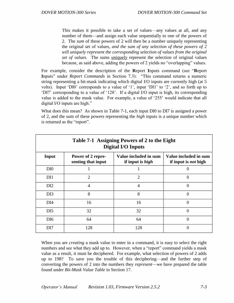
DOVER MOTION-300 Series DOVER MOTION-300 Command Set
Operator’s Manual Revision 1.03, Firmware Version 2.5.2 7-3
This makes it possible to take a set of values—any values at all, and any
number of them—and assign each value sequentially to one of the powers of
2. The sum of these powers of 2 will then be a number uniquely representing
the original set of values, and the sum of any selection of these powers of 2
will uniquely represent the corresponding selection of values from the original
set of values. The sums uniquely represent the selection of original values
because, as said above, adding the powers of 2 yields no “overlapping” values.
For example, consider the description of the Report Inputs command (see “Report
Inputs” under Report Commands in Section 7.3): “This command returns a numeric
string representing a bit-mask indicating which digital I/O inputs are currently high (at 5
volts). Input ‘DI0’ corresponds to a value of ‘1’, input ‘DI1’ to ‘2’, and so forth up to
‘DI7’ corresponding to a value of ‘128’. If a digital I/O input is high, its corresponding
value is added to the mask value. For example, a value of ‘255’ would indicate that all
digital I/O inputs are high.”
What does this mean? As shown in Table 7-1, each input DI0 to DI7 is assigned a power
of 2, and the sum of these powers representing the high inputs is a unique number which
is returned as the “report”.
Table 7-1 Assigning Powers of 2 to the Eight
Digital I/O Inputs
Input Power of 2 repre-
senting that input
Value included in sum
if input is high
Value included in sum
if input is not high
DI0 1 1 0
DI1 2 2 0
DI2 4 4 0
DI3 8 8 0
DI4 16 16 0
DI5 32 32 0
DI6 64 64 0
DI7 128 128 0
When you are creating a mask value to enter in a command, it is easy to select the right
numbers and see what they add up to. However, when a “report” command yields a mask
value as a result, it must be deciphered. For example, what selection of powers of 2 adds
up to 198? To save you the trouble of this deciphering—and the further step of
converting the powers of 2 into the numbers they represent—we have prepared the table
found under Bit-Mask Value Table in Section 17.
DOVER MOTION-300 Command Set DOVER MOTION-300 Series
7-4 Revision 1.03, Firmware Version 2.5.2 Operator’s Manual
7.1.4. Input Code Parameters
In DOVER MOTION-3x0 Versions 2.4.0 and later, a series of commands which use
"input code parameters" have been implemented. These parameters specify levels which
must be present at one or more pins of the Digital I/O Connector for the command to be
completed. In the case of the "jump" and "call" program commands, the command will be
executed if the given input code parameters are matched, and ignored if they are not
matched.
The input code parameters may be given as an "HLX"-type string, numeric "HL" codes,
or as one or two integer values in the range 0 to 255. Input code parameters are
represented in the command descriptions by the letter 'i'.
An "HLX-"type parameter string consists of 1 to 8 characters, with each character being
the letter 'H', 'L' or 'X'. An 'H' represents an input which will be checked for a "high" level
(>0 volts). An 'L' represents in input which will be checked for a "low" level (0 volts). An
'X' represents in input which will be not be checked. The right- most character in the
parameter string will correspond to digital input #0, the one beside it to input #1, and so
forth. For example, "HXXLLLXH" would be a valid "HLX"-type parameter string.
Numeric "HL"-style parameters each consist of a number in the range 0 through 7,
followed by an 'H' or an 'L' character. The number represents which digital input will be
checked. The 'H' or 'L' character represents what level the input will be checked for.
Unspecified inputs will be ignored. Any number of numeric "HL"-style parameters may
be entered, separated by commas or spaces. When conflicting parameters are entered
(such as "4L 4H 4L"), only the last parameter will be used (in this case, "4L"). As an
example, "0H, 2L,5L,7L" would be a valid set of "HL"-style parameters.

DOVER MOTION-300 Series DOVER MOTION-300 Command Set
Operator’s Manual Revision 1.03, Firmware Version 2.5.2 7-5
In the following examples, a '1' on the digital input side represents a high, a '0' represents
a low, and an 'x' represents an input which is not checked.
Digital Input #
Input Code 76543210
XXXXXXXH xxxxxxxl
XXXXXXXL xxxxxxx0
HXXLHXLH lxx0lx01
HXXL xxxxlxx0
H xxxxxxxl
L xxxxxxx0
0H xxxxxxxl
0L xxxxxxx0
3H xxxxlxxx
3L xxxx0xxx
0H, 3L,7L 0xxx0xxH
5L,1H,2H xx0xxllx
Numeric-integer input code parameters may be entered as decimal values, or as
hexidecimal values whenever a parameter is followed by an 'H'. If only one parameter is
entered, it is interpreted as an exact value which all eight bits the digital inputs must equal
in order for the condition to be met. If two input code parameters are given, they are
interpreted as a "mask" and a "value", respectively. In the "mask" parameter, the binary
bits which are set to '1' will specify the corresponding bits in the digital inputs that will be
checked. The other bits in the digital inputs will be ignored. In the "value" parameter, its
bit values determine what levels the corresponding digital input bits need to be at in order
for the condition to be met.
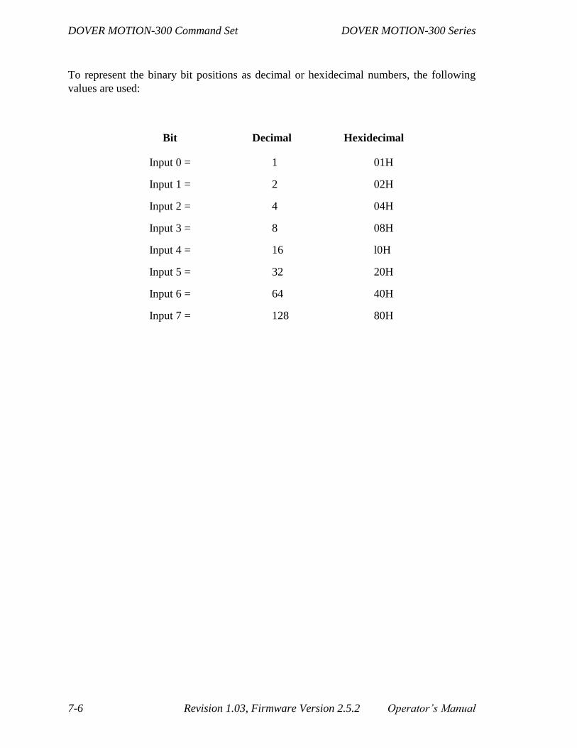
DOVER MOTION-300 Command Set DOVER MOTION-300 Series
7-6 Revision 1.03, Firmware Version 2.5.2 Operator’s Manual
To represent the binary bit positions as decimal or hexidecimal numbers, the following
values are used:
Bit Decimal Hexidecimal
Input 0 = 1 01H
Input 1 = 2 02H
Input 2 = 4 04H
Input 3 = 8 08H
Input 4 = 16 l0H
Input 5 = 32 20H
Input 6 = 64 40H
Input 7 = 128 80H

DOVER MOTION-300 Series DOVER MOTION-300 Command Set
Operator’s Manual Revision 1.03, Firmware Version 2.5.2 7-7
The decimal (and hexidecimal) values may be added together to specify multiple bits. In
the following examples, a '1' on the digital input side represents a high, a '0' represents a
low, and an 'x' represents an input which is not checked.
Input Code Digital Input #
i,i 76543210
1,1 xxxxxxxl
1,0 xxxxxxx0
2,2 xxxxxxlx
2,0 xxxxxx0x
3,3 xxxxxxll
3,0 xxxxxx00
8,8 xxxxlxxx
8,0 xxxx0xxx
15,15 xxxxllll
15,0 xxxx0000
16,16 xxxlxxxx
16,0 xxx0xxxx
128,128 lxxxxxxx
128,0 0xxxxxxx
255,255 11111111
255,0 00000000
1 00000001
0FFH 11111111
llH,10H xxxxlxx0
17,16 xxxxlxx0
22H,255 xxlxxxlx
0FFH,0FFH 11111111
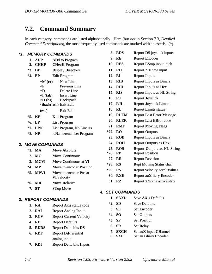
DOVER MOTION-300 Command Set DOVER MOTION-300 Series
7-8 Revision 1.03, Firmware Version 2.5.2 Operator’s Manual
7.2. Command Summary
In each category, commands are listed alphabetically. Here (but not in Section 7.3, Detailed
Command Descriptions), the most frequently used commands are marked with an asterisk (*).
*1. MEMORY COMMANDS
1. ADP ADd to Program
2. CHKP CHecK Program
*3. DD Display Directory
*4. EP Edit Program
^M (cr) Next Line
^P Previous Line
^D Delete Line
^I (tab) Insert Line
^H (bs) Backspace
\ (backslash) Exit Edit
(esc) Exit Edit
*5. KP Kill Program
*6. LP List Program
*7. LPN List Program, No Line #s
*8. NP reName/renumber Program
2. MOVE COMMANDS
*1. MA Move Absolute
2. MC Move Continuous
3. MCVI Move Continuous at VI
*4. MP Move to encoder Position
*5. MPVI Move to encoder Pos at
VI velocity
*6. MR Move Relative
7. ST STop Move
3. REPORT COMMANDS
1. RA Report Axis status code
2. RAI Report Analog Input
3. RCV Report Current Velocity
4. RD Report Defaults
5. RDDS Report Delta bits DS
6. RDF Report DiFferential
analog input
7. RDI Report Delta bits Inputs
8. RDS Report DS joystick inputs
9. RE Report Encoder
10. RES Report EStop input latch
11. RH Report Z/Home input
12. RI Report Inputs
13. RIB Report Inputs as Binary
14. RIH Report Inputs as Hex
15. RIS Report Inputs as HL String
16. RJ Report Joystick
17. RJL Report Joystick Limits
18. RL Report Limits status
19. RLEM Report Last Error Message
20. RLER Report Last ERror code
21. RMF Report Moving Flags
*22. RO Report Outputs
23. ROB Report Inputs as Binary
24. ROH Report Outputs as Hex
25. ROS Report Outputs as HL String
*26. RP Report Position
27. RR Report Revision
*28. RS Rept Moving Status char
*29. RV Report velocity/accel Values
30. RXE Report auXiliary Encoder
31. RZ Report Z/home active state
4. SET COMMANDS
1. SAXD Save AXis Defaults
*2. SD Save Defaults
3. SE Set Encoder
*4. SO Set Outputs
*5. SP Set Position
6. SR Set Relay
7. SXCH Set auX input CHannel
8. SXE Set auXiliary Encoder
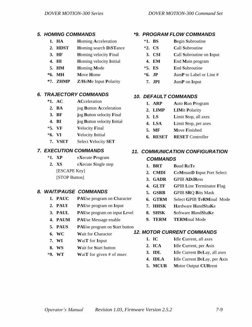
DOVER MOTION-300 Series DOVER MOTION-300 Command Set
Operator’s Manual Revision 1.03, Firmware Version 2.5.2 7-9
5. HOMING COMMANDS
1. HA Homing Acceleration
2. HDST Homing search DiSTance
3. HF Homing velocity Final
4. HI Homing velocity Initial
5. HM Homing Mode
*6. MH Move Home
*7. ZHMP Z/HoMe Input Polarity
6. TRAJECTORY COMMANDS
*1. AC ACceleration
2. BA jog Button Acceleration
3. BF jog Button velocity Final
4. BI jog Button velocity Initial
*5. VF Velocity Final
*6. VI Velocity Initial
7. VSET Select Velocity SET
7. EXECUTION COMMANDS
*1. XP eXecute Program
2. XS eXecute Single step
[ESCAPE Key]
[STOP Button]
8. WAIT/PAUSE COMMANDS
1. PAUC PAUse program on Character
2. PAUI PAUse program on Input
3. PAUL PAUse program on input Level
4. PAUM PAUse Message enable
5. PAUS PAUse program on Start button
6. WC Wait for Character
7. WI WaiT for Input
8. WS Wait for Start button
*9. WT WaiT for given # of msec
*9. PROGRAM FLOW COMMANDS
*1. BS Begin Subroutine
*2. CS Call Subroutine
3. CSI Call Subroutine on Input
4. EM End Main program
*5. ES End Subroutine
*6. JP JumP to Label or Line #
7. JPI JumP on Input
10. DEFAULT COMMANDS
1. ARP Auto Run Program
2. LIMP LIMit Polarity
3. LS Limit Stop, all axes
4. LSA Limit Stop, per axes
5. MF Move Finished
6. RESET RESET Controller
11. COMMUNICATION CONFIGURATION
COMMANDS
1. BRT Baud RaTe
2. CMDI CoMmanD Input Port Select
3. GADR GPIB ADdRess
4. GLTF GPIB Line Terminator Flag
5. GSRB GPIB SRQ Bits Mask
6. GTRM Select GPIB TeRMinal Mode
7. HHSK Hardware HandShaKe
8. SHSK Software HandShaKe
9. TERM TERMinal Mode
12. MOTOR CURRENT COMMANDS
1. IC Idle Current, all axes
2. ICA Idle Current, per Axis
3. IDL Idle Current DeLay, all axes
4. IDLA Idle Current DeLay, per Axis
5. MCUR Motor Output CURrent

DOVER MOTION-300 Command Set DOVER MOTION-300 Series
7-10 Revision 1.03, Firmware Version 2.5.2 Operator’s Manual
13. JOYSTICK COMMANDS
1. JA Joystick Acceleration
2. JC Joystick Center Value
3. JD Joystick Deadband
4. JE Joystick Enable
5. JG Joystick Gain
6. JIC Joystick Input Channel
7. JMAX Joystick MAX Limit
8. JMIN Joystick MIN Limit
9. JNL Joystick Negative Limit
10. JPL Joystick Positive Limit
11. JQI Joystick Qualifier Input
12. JZ Joystick Auto-Zero
14. MISCELLANEOUS COMMANDS
1. AA Select All Axes Mode
2. Ax Select Single Axis Mode
3. DC Display Character
4. DS Display String
5. DSN Display String, No LF
6. HELP Show HELP Screen
7. IOBN Select Current I/O-Board Number
8. LPUP Limit PullUP/down
9. UU User Units

DOVER MOTION-300 Series DOVER MOTION-300 Command Set
Operator’s Manual Revision 1.03, Firmware Version 2.5.2 7-11
7.3. Detailed Command Descriptions
7.3.1. Memory Commands
These commands manage the DOVER MOTION-300’s non-volatile memory, allowing
programs to be created, modified, deleted, etc. They are used in immediate mode only
(Sections 5 and 8), and have no meaning within programs.
7.3.1.1. ADP ADd to Program
This command differs from Edit Program (described in this section) only in that editing
begins after the last line of the existing program.
7.3.1.2. CHKP name/number CHecK Program
This command checks programs—identified by either name or number—for certain kinds
of errors. For example, it will find a jump (‘JP’) to a nonexistent line or label, or a call
(‘CS’) to a nonexistent subroutine. However, it will not find a call (‘XP’) to a
nonexistent program, or an ‘ES’ (End Subroutine) for a subroutine that was not begun or
called, even though these conditions will generate an error message and terminate the
program when encountered during program execution. It will not find errors in the form
of a command, such as a parameter value out of range or a parameter syntax error,
although these are usually caught by edit program as the program is being created.
Finally, if a program contains more than one error of a type that CHKP does find, it will
find only the first.
Simply running a program with XP (eXecute Program) will disclose any error that CHKP
would find—the error will be reported and program execution will not begin—so when a
“test-run” of the program is feasible there is no reason to run CHKP. (For complex
programs, the best test-run checking tool is eXecute Program, Single-Step—under
Execution Commands is Section 7.3).
However, there may times when a test-run of your program is not feasible or desirable. In
these situations, CHecK Program can be a handy, though limited, addition to your
programming arsenal.
7.3.1.3. DD Display Directory
This command displays all programs currently in memory, together with the program
number, the space each takes up, and the remaining memory space available. The
program number is automatically assigned as programs are created, and is used in
Thumbwheel and Auto Run execution of programs. A typical display is as follows:

DOVER MOTION-300 Command Set DOVER MOTION-300 Series
7-12 Revision 1.03, Firmware Version 2.5.2 Operator’s Manual
>dd
Directory of Programs
#: Program Name: Bytes:
1 X-THETS 48
2 SCAN 122
3 FOCUS 79
31751 bytes free
7.3.1.4. EP name/number Edit Program
This command allows you to create or modify programs and is the only way to do so. EP
followed by a new program name is used to enter edit mode for creating a program. For
editing an existing program, either the program name or number can be used. This
command can be given a second parameter which specifies a label or line number in the
program at which to begin the command's operation.
Creating a program: If the name used in the edit command does not match any
program in memory, a new program is created and editing begins at line 1. A
program name can be up to 20 characters, including numerals and most punctuation
marks, but cannot begin with a numeral or include a comma, question mark or
asterisk. Case variations in letters, while retained in the directory display, are treated
identically by the system (that is, “MoTIOn” and “motion” are considered to be one
and the same program).
Once a program name has been accepted you can proceed to type DOVER MOTION-
300 commands, terminating each with ENTER. As each command is entered,
sequential line numbers are automatically assigned. If the two (or more) typed
characters do not define a valid command, the prompt “Unrecognized Command” will
be displayed; backspace (see below) can then be used to correct the error.
You cannot create a program by using EP with an unassigned program number. An
error message will be returned, “No matching program number found.”
Modifying a program: If the name (or number) used when entering edit mode
matches that of an existing program, then the first line of that program will be
displayed. The special keys described below can then be used to advance forward or
backward through the program, with the ability to modify, insert and delete
commands. To append commands to the end of an existing program, simply use the
ADd to Program command (ADP), which operates like the Edit Program command
except that it begins editing after the last line of the program..

DOVER MOTION-300 Series DOVER MOTION-300 Command Set
Operator’s Manual Revision 1.03, Firmware Version 2.5.2 7-13
Six special keys or characters perform functions in edit mode, both while creating a
program and while modifying an already existing program:
1. (Ret) (CARRIAGE RETURN, ENTER, CTRL+M, or ASCII 13):
NEXT LINE advances you to the next line number. Repetitive
ENTERs sequentially display the program line by line. At any line,
you can make modifications with the backspace or delete key (see
below). AN ENTER beyond the last command of a program generates
a new line number and allows appending new commands to the
program.
2. CTRL+P (or ASCII 16): PREVIOUS LINE moves you backwards
through the program one line at a time—the opposite of ENTER. As
with ENTER, any line can be modified. However, after modifying a
line, you must hit ENTER to make the changes permanent. If you hit
CTRL+P immediately after editing a line, the changes will be lost.
Once you have “set” the changes with ENTER, you can safely use
CTRL+P to move to an earlier line, and you can even terminate the
edit session from an earlier line. The changes to any line are safe once
you have “set” them with ENTER.
3. CTRL+D (or ASCII 4): DELETE LINE deletes an existing program
line. After reaching the desired line using ENTER or CTRL+P, use
CTRL+D to delete the line. What had been the next command will be
displayed at this line number. The line numbers of all subsequent
commands will be decreased by one. By successive uses of DELETE
LINE, whole segments of existing programs can be erased.
All jump commands will automatically be changed to
reflect the deletion—for example, if line 52 is a conditional
jump to line 41, and line number 16 is deleted, line number 51
will now consist of a conditional jump to line number 40.
However, caution is still required: if the line to which the
jump command refers is deleted, the jump command will refer
to the same line number, which now contains the line that had
followed the line to which the jump command had referred.
No error message alerts you to the fact that a line to which a
jump command had referred was deleted.
4. CTRL+I (TAB, or ASCII 9): INSERT LINE inserts a new command
between two existing command lines. First, use ENTER(s) or
CTRL+P(s) to position the cursor on the command line before which
the new line is to be inserted. CTRL+I will then blank the command at
that line number, allowing you to enter a new command. The
command previously at that line number is moved up one in number

DOVER MOTION-300 Command Set DOVER MOTION-300 Series
7-14 Revision 1.03, Firmware Version 2.5.2 Operator’s Manual
(as are all subsequent commands). As with DELETE LINE, all JumP
commands are automatically modified to reflect the insertion.
5. Backspace (ASCII 8, or CTRL+H)/(ASCII 127): DELETE
CHARACTER erases characters within a command line. When a
command line is displayed, the cursor is left at the line’s end. By
successive deletes or backspaces, characters within the command are
blanked and may be re-entered. You can modify existing command
lines or correct errors as command lines are entered.
6. Escape (or ASCII 27): EXIT EDIT terminates all edit sessions. If line
with the cursor has just been modified, EXIT EDIT will cancel the
modification. However, changes—to that line or any other—made
prior to the cursor’s most recent arrival on that line will be preserved.
6. Backslash (\): EXIT EDIT. As an alternative to using the <Esc> key
to end the editing of a program, a backslash character ('\') may be
entered at the beginning of a line and followed by the <Enter> key to
end an edit. The "backslash" method can make it easier to download a
program from a computer interface.
7.3.1.5. KP name/number Kill Program
This command erases an existing program from memory, referring to it by either name or
number. An example would be KP SCAN (ret). This operation frees up memory for use
with new programs. Program numbers greater than that of the killed program remain
assigned to the same programs, so a gap is created in the program numbering. Thus the
Kill Program command can be used to allow a new program (or, in conjunction with the
reName or Renumber Program command, an existing program with a high number) to
receive a low number (below 90) in order to be executable by thumbwheel.
7.3.1.6. LP name/number List Program
This command allows a program to be examined, but without the ability to modify its
contents. The program can be referred to either by name or by number, as shown above.
This command can be given a second parameter which specifies a label or line number in
the program at which to begin the command's operation.
LP XYZMOVE lists the program XYZMOVE
LP 17 lists program #17
The program listing can be paused and resumed by typing Ctrl+S and Ctrl+Q,
respectively (provided that software handshaking is enabled—see Section 4).

DOVER MOTION-300 Series DOVER MOTION-300 Command Set
Operator’s Manual Revision 1.03, Firmware Version 2.5.2 7-15
7.3.1.7. LPN name/number (n1)(,n2) List Program, No
Line Numbers
This command differs from List Program only in that there are no line numbers preceding
each line in the listing. This command can be given a second parameter which specifies a
label or line number in the program at which to begin the command's operation.
7.3.1.8. NP oldname[,] newname reName or Renumber
Program
NP oldnumber[,] newnumber
NP number[,] newname
NP name[,] newnumber
This command allows the name or number of a previously stored program to be changed.
(See Edit Program in Section 7.3.1 for allowable program names.) An example is: NP
TEST1995, TEST1996 (ret) (or NP TEST1995 TEST1996 (ret)—the comma is
optional). The program can be referred to by either its current name or its current
number. In either case, either the name or the number can be changed, depending on
whether the second parameter begins with a letter or a numeral. If the name of the
program is changed, its program number is unchanged; and vice versa. If the new name
or number is already taken by another program, an error message reports this fact and the
change is not made.
Changing the program number can be very useful because only programs 1 through 89
can be run by thumbwheel selection directly from the DOVER MOTION-300. If you
have just written program #120, for example, you could assign it to a number 89 with
this command. (If all the earlier program numbers are taken, you could make room for it
either by deleting an earlier program or by using this command to assign an earlier
program to #121.)
DOVER MOTION-300 Command Set DOVER MOTION-300 Series
7-16 Revision 1.03, Firmware Version 2.5.2 Operator’s Manual
7.3.2. Move Commands
These commands rotate the stepping motor and thus move the stage. The motor can be
stopped during a move by pressing either the STOP button on the DOVER MOTION-300
or the ESCAPE key (ASCII 27) on the computer or terminal. In either case, the motor
will decelerate to a stop at the previously programmed deceleration rate (Section 7.3).
Move commands function in both immediate and program modes.
Other immediate-mode commands (except other moves and Set Position) can be executed
while an immediate-mode move command is being executed. In particular, Report Status
returns an ‘M’ during the execution of a move command and an ‘F’ if it is finished.
A convenient alternative to continuous polling via Report Status is to enable Move
Finished. This causes an ‘F’ (ASCII 70) to be issued at the completion of the move.
If the limit input corresponding to the move direction is activated—by the moving axis
encountering the limit position—motion in that direction will immediately stop;
movement away from the limit will be allowed, however. The Limit Stop function (see
“Limit Stop” under Default Commands in Section 7.3), when enabled, allows a host to be
notified and program execution terminated upon limit activation.
Motor current can be reduced or eliminated at standstill by use of the idle current
commands (see “Idle Current, all axes” and “Idle Current, per Axis”under Default
Commands in Section 7.3).
7.3.2.1. MA n [,n...] Move Absolute
This command moves the current axis or axes to the given position(s), performing a
ramped trajectory move. It differs from Move Relative in that the destination depends
only on the coordinates and not on the starting position—the coordinates represent the
location of the end-point rather than the distance to be traveled. The velocities and
accelerations used are specified by the Velocity Initial, Velocity Final and ACceleration
commands (see Trajectory Commands in Section 7.3).
The value of the units used depends on the User Units command (see “User Units” in
Section 7.1 and under Miscellaneous Commands in Section 7.3). The maximum distance
able to be traversed in a single move command (“desired position” minus “current
position”) is 16777215 (when user units = 1); larger move commands will generate
command errors. The position for an axis may range from –2147483648 to 2147483647
(when user units = 1).
DOVER MOTION-300 Series DOVER MOTION-300 Command Set
Operator’s Manual Revision 1.03, Firmware Version 2.5.2 7-17
7.3.2.2. MC [f [,f...]] Move Continuous
This command moves the current axis or axes in the given direction(s) indefinitely until
stopped by a travel limit, a user command, or ESTOP Input Latch Reset (see “ESTOP
Input Latch Reset” under Miscellaneous Commands in Section 7.3) and Report
Emergency Stop under Report Commands in Section 7.3). It begins a ramped trajectory
move—how the move completes depends on how it is stopped. The velocities and
accelerations used are specified by the Velocity Initial, Velocity Final and ACceleration
commands (under Trajectory Commands in Section 7.3). The command’s flag parameter
may be a ‘+’ for a positive direction move, or a ‘– ’ for negative. In single-axis mode
(“Ax”), the “MC” command may be entered with no parameters to initiate a positive
direction move for the currently selected axis; in all-axes mode (“AA”), parameters are
required.
7.3.2.3. MCVI [f [,f...]] Move Continuous at VI Velocity
The “MCVI” command is identical to the “MC” command except that the velocity
remains at the initial velocity (“VI”). No velocity ramping is performed.
7.3.2.4. MP n [,n...] Move to Encoder Position
This command moves the current axis or axes to the given encoder position(s),
performing a ramped trajectory move. The velocities and accelerations used are specified
by the "VI", "VF", and "AC" commands. Note that any velocity deceleration ramping
will occur after the given encoder position is reached, appearing as "overshoot" past the
position. The Move to Encoder Position at VI Velocity command (MPVI) (see in this
section) may be used in place of or after the "MP" command to correct for this position
"overshoot". The units used are encoder counts, and are not affected by the user-units
value (see the "UU" command).
Parameter range: '-8388608' to '8388607'.
7.3.2.5. MPVI n [,n...] Move to Encoder Position at VI
Velocity
This command is identical to the Move to Encoder Position command ("MP") except
that, while the move is in progress, the velocity is constantly at the "VI" velocity speed.
(No velocity ramping is performed.) This results in more accurate positioning. The "VI"
velocity value may be lowered to further improve accuracy.

DOVER MOTION-300 Command Set DOVER MOTION-300 Series
7-18 Revision 1.03, Firmware Version 2.5.2 Operator’s Manual
7.3.2.6. MR n [,n...] Move Relative
This command moves the current axis or axes by the given distance(s), performing a
ramped trajectory move. It differs from Move Absolute in that the destination depends
not only on the coordinates but also on the starting position—the coordinates represent
the distance to be traveled rather than the location of the end-point. The velocities and
accelerations used are specified by the Velocity Initial, Velocity Final and ACceleration
commands (under Trajectory Commands in Section 7.3).
The value of the units used depends on the User Units command (see “User Units” in
Section 7.1 and under Miscellaneous Commands in Section 7.3). The maximum distance
able to be traversed in a single move command (“desired position” minus “current
position”) is 16777215 (when user units = 1); larger move commands will generate
command errors. The position for an axis may range from –2147483648 to 2147483647
(when user units = 1).
The position reading may change in anomalous ways when you execute a
Move Relative command to a position that is within the range of motion of
the axis but beyond the range (–2147483648 to 2147483647) of the Set
Position/Report Position parameter.
7.3.2.7. ST STop Move
The “ST” command is used to stop moves in progress. In single-axis mode (“Ax”), only
the current axis is stopped. In all-axes mode (“AA”), all the axes are stopped. This
command may also be used to terminate joystick mode (see “Joystick Enable” under
Joystick Commands in Section 7.3).
The ESCAPE key (ASCII 27) or the front-panel STOP button are often more
convenient than STop Move, especially since the latter cannot be used during
a program. Table 7-2 compares these three ways of “stopping the action.”

DOVER MOTION-300 Series DOVER MOTION-300 Command Set
Operator’s Manual Revision 1.03, Firmware Version 2.5.2 7-19
Table 7-2 Stopping the Action: Three Methods Compared
STop Move ESCAPE Key STOP Button1
Stops a move in progress YES NO YES
Stops a move in progress
during a program NO2 YES YES
Aborts execution of a
program NO YES3 YES3
1 In firmware releases 2.0.0 and earlier, if the current thumbwheel setting configures
the front-panel START and STOP buttons as jog buttons for any axis, then they
will not function as START and STOP buttons except during a Wait for Start
command. Instead, they will function as jog buttons. They will terminate and
supersede moves in the axis for which they are configured, but will have no effect
on moves in other axes and will not terminate programs. See Jog Functions in
Section 4. In later firmware releases, even if the START and STOP buttons are
configured as jog buttons by the thumbwheel setting, they revert to their “stop” and
“start” functions when a program is run, although only STOP should be used.
2 This is because a Stop command within a program is not executed until moves
initiated earlier in the program are completed. Also, commands cannot be issued
from the keyboard during program execution. However, a STop command within
a program will stop an ongoing move initiated prior to program execution.
3 However, if the aborted program had been called with the eXecute Program
command by another program, the program that called it is not aborted.

DOVER MOTION-300 Command Set DOVER MOTION-300 Series
7-20 Revision 1.03, Firmware Version 2.5.2 Operator’s Manual
7.3.3. Report Commands
This set of commands returns ASCII characters representing the state of the DOVER
MOTION-300 and/or external devices. No additional data is required other than the two
(or more) characters of the command itself. All report commands function in both
immediate and program modes.
7.3.3.1. RA Report Axis Status Code
This report command returns a numeric string value corresponding to the motion status of
the current axis or axes (depending on whether the controller is in single-axis mode
(“Ax”) or all-axes mode (“AA”)). In all-axis mode, Report Axis Status Code returns a
number for each axis, separated by commas. The codes returned are as follows:
0 = Axis not moving (and not in joystick mode).
1 = Axis performing normal trajectory move.
2 = Axis homing; moving towards limit.
3 = Axis homing; moving out of limit.
4 = Axis in joystick mode (whether moving or not).
Joystick mode is explained in Section 7.3.11 Trajectory moves are explained in Section
7.3.6. Homing is explained in Section 7.3.5.
7.3.3.2. RAI n Report Analog Input
The “RAI” command performs an analog-to-digital conversion of the voltage level at the
given analog input, and returns a numeric string representing the converted value.
(Typically—but not necessarily—analog inputs ‘AN1’ through ‘AN6’ are assigned to
various joystick motions as described in Section 13, Joystick Interface.) If no parameter
is given, the analog input specified in the most recent “RAI” command is used (or the
first input (‘1’) if no previous “RAI” command was issued). For analog inputs ‘AN1’
through ‘AN6’, the input voltage range of 0.0 through 5.0 volts results in returned values
of ‘0’ through ‘4095’. Analog inputs ‘AN7’ and ‘AN8’ are usually factory configured to
the same voltage input range and returned values, but may be adjusted via on-board
socketed gain resistors.
Note that the values returned by this command will be different from those returned by
the Report Joystick command (under Joystick Commands in Section 7.3) because of the
joystick center-offset value subtracted from the converted analog input by that command.
Parameter range: ‘1’ to ‘8’.

DOVER MOTION-300 Series DOVER MOTION-300 Command Set
Operator’s Manual Revision 1.03, Firmware Version 2.5.2 7-21
7.3.3.3. RCV Report Current Velocity
This command returns the current actual velocity (not the setting) for the given axis or
axes. The value of the units used depends on the User Units command (see “User Units”
in Section 7.1 and under Miscellaneous Commands in Section 7.3).
7.3.3.4. RD Report Defaults
This command returns the current settings—whether these are the default settings or
not—for the commands Auto Run Program, Move Finished, Select Velocity SET, Set
AuXiliary Encoder Input CHannel, Set TERMinal Mode, CoMmanD Input Port Select,
Baud RaTe, Software HandShaKe Mode and Hardware HandShaKe Mode.
When GPIB hardware is installed and detected by the software, RD also
returns the current settings for GPIB SRQ Bits Mask and GPIB Line
Terminator Flag. Furthermore, in GPIB mode the “TERM” reading is
identical to that for Select GPIB TeRMinal Mode.)
For some of these commands (ARP, CMDI, BRT SHSK, HHSK), any setting is a
default because the current setting remains when the machine is turned OFF and then ON.
For others (MF, VSET, SXCH, TERM, and the GPIB commands GLTF, GSRB) a
change in the current setting does not become a new default (activated upon power-up)
unless the Save Defaults command is executed prior to turning the machine off.
For a more complete discussion of reading default settings, see Section 15, Default States.
7.3.3.5. RDDS Report Delta-Bits for DS Inputs
This command returns a numeric string representing a bit-mask indicating which joystick
‘DS’ inputs have had any state changes since the last time they were read with the “RDS”
command (or since power-up if no “RDS” commands have been issued). (see Bit-Masks
in Section 7.1) Joystick input ‘DS1’ corresponds to a value of ‘1’, input ‘DS2’ to ‘2’,
input ‘DS3’ to ‘4’, and input ‘DS4’ to ‘8’. If a joystick input has changed state one or
more times, its corresponding value is added to the “delta-bit” mask value. For example,
a value of ‘15’ would indicate that all joystick inputs have had state changes. Executing
the “RDS” (Report DS Joystick Inputs) command clears this mask value to zero. The
“RDDS” command is useful in determining if a device attached to a joystick input (such
as a momentary push-button switch) has been activated since the last time it was checked.
7.3.3.6. RDF n Report DiFferential Analog Input
Parameter range: ‘1’ to ‘8’.

DOVER MOTION-300 Command Set DOVER MOTION-300 Series
7-22 Revision 1.03, Firmware Version 2.5.2 Operator’s Manual
7.3.3.7. RDI Report Delta-Bits for Inputs
This command returns a numeric string representing a bit-mask indicating which digital
I/O inputs have had any state changes since the last time they were read with the “RI”
command (or since power-up if no “RI” commands have been issued). (See Bit-Masks in
Section 7.1.) Input ‘DI0’ corresponds to a value of ‘1’, input ‘DI1’ to ‘2’, and so forth up
to ‘DI7’ corresponding to a value of ‘128’. (Note that this is a geometric rather than an
arithmetic progression—and that the second character in “DI0” is the letter I, not the
numeral 1.) If a digital I/O input has changed state one or more times, its corresponding
value is added to the “delta-bit” mask value. For example, a value of ‘255’ (= 1 + 2 + 4 +
8 + 16 + 32 + 64 + 128) would indicate that all digital I/O inputs have had state changes.
Executing the “RI” (Read Inputs) command clears this mask value to zero.
The “RDI” command is useful in determining if a device attached to a digital I/O input (such
as a momentary push-button switch) has been activated since the last time it was checked.
7.3.3.8. RDS Report DS Joystick Inputs
The “RDS” command returns a numeric string representing a bit-mask indicating which
joystick ‘DS’ inputs are currently high (at 5 volts). (See Bit-Masks in Section 7.1.)
Joystick input ‘DS1’ corresponds to a value of ‘1’, input ‘DS2’ to ‘2’, input ‘DS3’ to ‘4’,
and input ‘DS4’ to ‘8’. (Note that this is a geometric rather than an arithmetic
progression.) If a joystick input is high, its corresponding value is added to the mask
value. For example, a value of ‘15’ would indicate that all joystick inputs are high.
When this command is executed, the delta-bit-mask value reported by the “RDDS”
command is set to zero.
7.3.3.9. RE Report Encoder
This command returns a numeric string representing the encoder position(s) of the current
axis or axes. The units used are encoder counts, and are not affected by the user-units value
(see “User Units” in Section 7.1 and under Miscellaneous Commands in Section 7.3).
7.3.3.10. RES Report EStop Input Latch
The “RES” command reports the status of the hardware latch triggered by an ESTOP
input (see “ESTOP Input Latch Reset” under Miscellaneous Commands in Section 7.3).
The ESTOP input signal is generated by asserting low pin 22 of the DB-25S I/O rear-
panel connector, or through the use of the internal ESTOP connector. After ESTOP is
asserted, the ESTOP input latch remains active, inhibiting all axis motion, until the
“ESR” command is executed. This command returns a ‘1’ if the latch is active, ‘0’ if not.
Note that the ESTOP latch is triggered by the transition of an ESTOP input from high to
low. The latch may be reset (by “ESR”) even while the ESTOP input remains active—it
must become inactive (high) and then active again (low) to retrigger the latch.

DOVER MOTION-300 Series DOVER MOTION-300 Command Set
Operator’s Manual Revision 1.03, Firmware Version 2.5.2 7-23
7.3.3.11. RH Report Z/Home Input
The "RH" command reports the state of the home/index input for the current axis or axes.
An 'H' is returned to indicate an input in the "high" (+5V) state, or an 'L' is returned to
indicate an input in the "low" (ground) state. The reports returned by this command are
not affected by the "Z/HoMe Input Polarity" command (under Homing Commands in
Section 7.3).
7.3.3.12. RI Report Inputs
This command returns a numeric string representing a bit-mask indicating which digital
I/O inputs are currently high (at 5 volts). (See Bit-Masks in Section 7.1.) Input ‘DI0’
corresponds to a value of ‘1’, input ‘DI1’ to ‘2’, and so forth up to ‘DI7’ corresponding to
a value of ‘128’. (Note that the second character in “DI0” is the letter I, not the numeral
1.) If a digital I/O input is high, its corresponding value is added to the mask value. For
example, a value of ‘255’ (= 1 + 2 + 4 + 8 + 16 + 32 + 64 + 128) would indicate that all
digital I/O inputs are high. When this command is executed, the delta-bit-mask value
reported by the “RDI” command is set to zero.
7.3.3.13. RIB Report Inputs as Binary
This command displays the current status of the digital inputs as a binary numeric string
of 8 characters, where each character is a '1' or a '0'. The rightmost character represents
input #0, the one to its left represents input #1, and so forth up to the leftmost character,
which represents input #7. A '1' indicates an input in the "high" (>0 volts) state, while a '0'
indicates an input in the low (0 volts) state.
7.3.3.14. RIH Report Inputs as Hex
This command displays the current status of the digital inputs as an hexidecimal numeric
string.
7.3.3.15. RIS Report Inputs as HL String
This command displays the current status of the digital inputs as a string of 8 characters,
where each character is an 'H' or an 'L'. The rightmost character represents input #0, the
one to its left represents input #1, and so forth up to the leftmost character, which
represents input #7. An 'H' indicates an input in the "high" (>0 volts) state, while an 'L'
indicates an input in the low (0 volts) state.
7.3.3.16. RJ Report Joystick
This command reports as a numeric string the joystick input value, which (with usual
input connections) basically represents for each axis the deviation of the joystick itself

DOVER MOTION-300 Command Set DOVER MOTION-300 Series
7-24 Revision 1.03, Firmware Version 2.5.2 Operator’s Manual
from its center position (defined with the Joystick Center Value command or the
Joystick Auto-Zero command). Usually, of course, the center position will be vertical.
Determining the joystick input for a given axis involves two steps:
an analog input voltage that varies with the position of the joystick itself is converted
to a digital value in a 12-bit analog-to-digital conversion, as explained under Reading
and Setting Joystick Values in Section 13. This digitized value rises (or falls)
continuously as the joystick sweeps through its arc from one side to the other;
the joystick center value (set with the Joystick Center Value command or the Joystick
Auto-Zero command) is subtracted from this digitized input value, so as to give the
joystick input a value of zero at the center (vertical) position.
If the joystick center value has been set with the Joystick auto-Zero command while the
joystick was in a vertical position, the joystick input value (analog input voltage minus
center value) is negative when the joystick is pushed to one side, positive when pushed to
the other side, and is usually approximately proportional to the angular displacement of
the joystick from the vertical. This value plays a key role in setting the joystick target
velocity, as described in Section 13.
In all-axis mode, Report Joystick returns a number for each axis, separated by commas.
When a joystick input is attached to a joystick device, the returned values should be near
zero when the joystick is centered, and be a positive or negative value when the joystick
is moved away from center. The Joystick Zero command may be used to set the center
zero value (see Joystick Commands in Section 7.3).
Normally, the digitized analog input voltage fed into the joystick input calculation
for each axis is that which varies with the joystick position in that axis. (The
various (digitized) analog inputs can be read with the Report Analog Input
command.) However, the Joystick Input Channel command (under Joystick
Commands in Section 7.3) can be used to connect any of the eight analog input
lines with any of the joystick axes, allowing for sophisticated guidance patterns for
the joystick control. If the input for a given axis represented the output of some
device, then the joystick input value—and hence the motion of that axis—would
be controlled by that device rather than by the position of the joystick handle.
7.3.3.17. RJL Report Joystick Position Limits
This command reports the joystick travel-limit status of the current axis or axes. These
software position limits are set by the “JNL” and “JPL” commands (see Joystick
Commands in Section 7.3). An active limit indicates that the axis has traveled beyond the
limit position. If no joystick limits are active for an axis, an ‘x’ is returned. If the
positive direction joystick limit is active, a ‘+’ is returned. If the negative direction
joystick limit is active, a ‘–’ is returned. If both joystick limits are active (e.g., if JPL is
set to a value less then JNL), a ‘+-’ is returned. This command will show when the

DOVER MOTION-300 Series DOVER MOTION-300 Command Set
Operator’s Manual Revision 1.03, Firmware Version 2.5.2 7-25
current position is beyond a joystick limit regardless of whether or not joystick mode is
active.
7.3.3.18. RL Report Limits Status
This command reports the travel limit status of the current axis or axes. If no limits are
active for an axis, an ‘x’ is returned. If the positive direction travel limit is active, a ‘+’ is
returned. If the negative direction travel limit is active, a ‘–’ is returned. If both travel
limits are active, a ‘+-’ is returned. If more than one axis is current, the status of each
will be reported in sequence, separated by commas on a single line.
An active limit indicates that the axis has traveled beyond the limit position.
If both the positive and negative limits are active, this indicates either that the
axis is not set up or that there may be a wiring or limit hardware problem.
The position of each limit is factory-set to avoid mechanical damage to the
stage. Limit-positions cannot be changed by any software command.
7.3.3.19. RLEM Report Last Error Message
The “RLEM” command returns the text associated with the last command error that
occurred. If no errors have occurred, the text “No Error” will be returned. This
command is useful when a terminal mode (see “TERMinal Mode” under Communication
Configuration Commands in Section 7.3) is selected which does not generate command
error messages—it can be used to fetch the error message text after the error is detected.
The command error codes and associated messages are given in Table 7-3.

DOVER MOTION-300 Command Set DOVER MOTION-300 Series
7-26 Revision 1.03, Firmware Version 2.5.2 Operator’s Manual
Table 7-3 DOVER MOTION-300 Series Error–
Codes and Messages Reported by RLEM & RLER
Code Message
0 No error
1 Hardware error initializing serial port
2 Hardware error initializing timer channel
3 Hardware error initializing axis functions
4 Unrecognized command
5 Command not implemented
6 Command not allowed for axis type
7 No parameters allowed for command
8 Illegal numeric parameter
9 Required parameter(s) missing for command
10 Parameter(s) required in all-axes mode
11 Too many parameters for single axis mode
12 Too many parameters for command
13 Parameter value out of range
14 Fractional parameter value not allowed
15 Axis select letter out of range
16 Parameter syntax error
17 Query invalid for command
18 Parameter(s) not allowed in query command
19 Emergency Stop detected, enter 'ESR' to clear
20 Command not allowed while any axis in motion
21 Initial velocity (VI) greater then final (VF)
22 Initial homing vel (HI) greater then final (HF)
23 Move distance too large
24 Command not allowed in all-axes mode
25 Unable to recover NVRAM, resetting to defaults

DOVER MOTION-300 Series DOVER MOTION-300 Command Set
Operator’s Manual Revision 1.03, Firmware Version 2.5.2 7-27
Table 7-3 DOVER MOTION-300 Series Error–
Codes and Messages Reported by RLEM & RLER
Code Message
26 NVRAM error, recovered from backup copy
27 Unrecognized front panel input detected [Bad
button/thumbwheel combination upon power-up/reset.]
28 Unable to initialize program memory area [System
error—call factory.]
29 Unable to allocate—out of program memory
30 Unable to recover program memory area, resetting
[Programs & settings in non-volatile memory were lost.]
31 Program name required
32 Program name too long
33 Program name already in use
34 Program number already in use
35 Illegal characters in program name
36 No matching program names found
37 No matching program numbers found
38 Program is currently executing
39 Command not allowed in a program
40 Command only allowed in a program
41 Illegal label--must start with a letter
42 Illegal characters in label
43 Duplicate label in program
44 No matching line or label for command
45 JP to BS command not allowed
46 Unable to execute Call Sub--out of memory
47 No Call Sub executed for End Sub command
48 Unable to execute command: out of memory
49 Program aborted, axis in limit detected
50 User abort input detected

DOVER MOTION-300 Command Set DOVER MOTION-300 Series
7-28 Revision 1.03, Firmware Version 2.5.2 Operator’s Manual
Table 7-3 DOVER MOTION-300 Series Error–
Codes and Messages Reported by RLEM & RLER
Code Message
51 No matching entry for Auto Run Program #
52 Error initializing GPIB port [GIPB option not installed
or system error.]
53 Error allocating GPIB I/O buffers [System error—call
factory.]
54 Hardware error initializing axis board [System error—
call factory.]
55 Hardware error initializing I/O board [System error—
call factory.]
56 Memory error initializing axis-I/O functions [System
error—call factory.]
57 Internal memory allocation error [System error—call
factory.]
7.3.3.20. RLER Report Last ERror code
The “RLER” command returns a numeric string representing the error code associated
with the last command error that occurred. If no errors have occurred, the code ‘0’ will
be returned. This command is useful when a terminal mode (see “TERMinal Mode”
command, under Communication Configuration Commands in Section 6.3) is selected
which does not generate command error messages—it can be used to fetch the error code
after the error is detected. See the description of the “RLEM” command for a list of
command error codes and messages.
7.3.3.21. RMF Report Moving Flags
This command returns essentially the same information as Report Moving Status
Character, but represented by a bit-mask rather than one or more characters, thus enabling
a computer to receive the moving status of all axes in one numeric value. The command
returns a numeric string representing the moving status of all the axes in the controller.
The number is a decimally represented unsigned 16-bit integer. Each axis corresponds to
a binary bit position in the number, where ‘X’ is ‘1’, ‘Y’ is ‘2’, ‘Z’ is ‘4’. When an axis is
moving, its bit is set to one. Therefore, when no axes are moving, the command returns

DOVER MOTION-300 Series DOVER MOTION-300 Command Set
Operator’s Manual Revision 1.03, Firmware Version 2.5.2 7-29
‘0’. Examples: When only the ‘Z’ axis is moving, ‘4’ is returned. When the only the ‘X’
and ‘Z’ axes are moving, ‘5’ is returned (‘1’+‘4’).
7.3.3.22. RO Report Outputs
This command returns a numeric string representing a mask value which indicates the
current states of the digital I/O outputs, using the same scheme as the Set Outputs
command. (See Bit-Masks in Section 7.1, and Set Outputs under Set Commands in
Section 7.3).
7.3.3.23. ROB Report Outputs as Binary
This command displays the current status of the digital outputs (which are set by the "Set
Output" ("SO") command) as a binary numeric string of 8 characters, where each
character is a '1' or a '0'. The rightmost character represents output #0, the one to its left
represents output #1, and so forth up to the leftmost character, which represents output
#7. A '1' indicates an output in the "high" (>0 volts) state, while a '0' indicates an output
in the low (0 volts) state.
7.3.3.24. ROH Report Outputs as Hex
The "ROM" command displays the current status of the digital outputs (which are set by
the "Set Output" ("SO") command) as an hexidecimal numeric string.
7.3.3.25. ROS Report Outputs as HL String
This command displays the current status of the digital outputs (which are set by the "Set
Output" ("SO") command) as a string of 8 characters, where each character is an 'H' or an
'L'. The rightmost character represents output #0, the one to its left represents output #1,
and so forth up to the leftmost character, which represents output #7. An 'H' indicates an
output in the "high" (>0 volts) state, while an 'L' indicates an output in the low (0 volts)
state.
7.3.3.26. RP Report Position
The “RP” command returns a numeric string representing the position(s) of the current
axis or axes. The value of the units used depends on the User Units command (see User
Units in Section 7.1 and under Miscellaneous Commands in Section 7.3). In all-axes
mode, the position of each axis is given, separated by commas on a single line.

DOVER MOTION-300 Command Set DOVER MOTION-300 Series
7-30 Revision 1.03, Firmware Version 2.5.2 Operator’s Manual
7.3.3.27. RR Report Revision
The “RR” command returns a revision string which indicates the name and version level
of the controller. The format is as follows: “DOVER MOTION-xxx Version y.y.y”,
where “xxx” would be the model number and “y.y.y” would be the version level of the
controller.
7.3.3.28. RS Report Moving Status Character
This command returns a string which indicates the motion status of the current axis or
axes. If an axis is in motion, an ‘M’ is returned. If an axis is not in motion, an ‘F’ is
returned. In all-axes mode, a value is returned for each axis, separated by commas. This
command returns essentially the same information as Report Moving Flags, but
represented by one or more characters rather than a bit-mask.
7.3.3.29. RV Report Velocity/Acceleration Values
This command reports the current initial velocity, final velocity, and acceleration, as well
as the homing versions of these, for the current axis or axes. For single-axis mode
(“Ax”), the report format looks like this:
“VI n, VF n, AC n, HI n, HF n, HA n”
where each ‘n’ is the corresponding value. For all-axes mode (“AA”), each axis in the
controller has a line in the output:
“Axis #x, VI n, VF n, AC n, HI n, HF n, HA n”
where ‘x’ is the number of the axis being outputted (‘0’ for ‘X’, ‘1’ for ‘Y’, etc.). In
certain terminal modes, only the velocity and acceleration numeric strings and the comma
separators are returned by the “RV” command (see “TERMinal Mode” under
Communication Configuration Commands in Section 7.3).
The velocity and acceleration settings actually used by the controller may
differ somewhat from those set by the user (see note at the beginning of
Trajectory Commands, Section 7.3.6). Furthermore, changes in the setting of
one parameter can affect the actual setting used for another. Therefore, if
exact values of trajectory variables are important to your application, it is wise
to check the Report Velocity/Acceleration Values command after setting all
variables.
7.3.3.30. RXE Report AuXiliary Encoder
The “RXE” command returns a numeric string representing the current value in the
auxiliary encoder counter—this counter is separate from other axis hardware, and is used

DOVER MOTION-300 Series DOVER MOTION-300 Command Set
Operator’s Manual Revision 1.03, Firmware Version 2.5.2 7-31
primarily in generating output pulses at preprogrammed axis positions. The units used
are encoder counts, and are not affected by the user-units value (see “User Units” in
Section 7.1 and under Miscellaneous Commands in Section 7.3). The Set AuXiliary
Encoder Input CHannel command is used to set the input source for the counter (see
under Set Commands in Section 7.3).
7.3.3.31. RZ Report Z/Home Active State
This command reports the active state of the home/index input for the current axis or
axes. An '1' is returned to indicate an active home/index input, or a ‘0’ is returned to
indicate an inactive input. The actual input level (high/low) corresponding to an active
state is determined by the "Z/HoMe Input Polarity" command (under Homing Commands
in Section 7.3).

DOVER MOTION-300 Command Set DOVER MOTION-300 Series
7-32 Revision 1.03, Firmware Version 2.5.2 Operator’s Manual
7.3.4. Set Commands
7.3.4.1. SAXD Save AXis Defaults
This command is similar to the Save Defaults command (below), but differs in two
respects:
1. It affects only those variables that can have distinct values for each axis;
2. If the command is executed while in single-axis mode, only variables in the selected
axis are affected.
The affected variables are:
Trajectory & homing commands (BA, BI, BF; AC, VI, VF; HDST, HM, HA, HI, HF,
ZHMP)
Joystick commands (JA, JC, JG, JIC, JMAX, JMIN, JNL, JPL, JQI, JZ)
Default commands (IC, ICA, IDL*, IDLA, LIMP*, LS†, LSA)
Miscellaneous commands (LPUP, UU)
* A new LIMit Polarity default can be set by the Save AXis Defaults command in
firmware releases later than version 2.0.0.
† The variables set by LS and IDL are affected by the Save AXis Defaults command,
even though these commands cannot themselves change the values of their varables
on a per-axis basis, because the variables are nevertheless assigned to specific axes.
The advantage of this command is that it allows you to change the default settings for
axis variables without affecting the defaults of any non-axis variables you may have also
changed during the current session that would be affected if you used the Save Defaults
command instead. Furthermore, you can change the defaults for one axis while leaving
the settings for other axes unaffected.
7.3.4.2. SD Save Defaults
This command, when executed, sets the current values of a number of variables as the
new default values, to which the system will revert upon power-up. Each of these
variables can be changed as the parameter of some other command, but the new values
are usually lost when the machine is turned off. The Save Defaults command stores the
current value of these variables in non-volatile memory, making any new values
permanent. However, defaults set with the Save Defaults command can be overridden by
Master Reset (Section 4.7), which returns all defaults to their factory settings. (For a list
of the factory-set defaults, see Section 15, Default States.)
Although the Save Defaults command affects variables that are parameters of other
commands, it accepts no parameters itself, but rather resets the values of all of these
variables at once. (By contrast, the Save AXis Defaults command allows you to set
defaults for just the variables which are axis-specific, and to set them on either an all-axes

DOVER MOTION-300 Series DOVER MOTION-300 Command Set
Operator’s Manual Revision 1.03, Firmware Version 2.5.2 7-33
or a per axis basis—but, like Save Defaults, it sets all such variables at once without
allowing parameters.) The variables affected are:
Communication configuration commands (GLTF, GSRB, TERM)
Default commands (IC, ICA, IDL, IDLA, LS, MF)
Joystick commands (JA, JC, JG, JIC, JMAX, JMIN, JNL, JPL, JZ)
Miscellaneous commands (LPUP, UU)
Set commands (SR, SXCH)
Trajectory & homing commands (BA, BI, BF; AC, VI, VF; HDST, HM, HA, HI, HF;
& VSET, ZHMP)
Caution: Save Defaults changes the defaults of all these variables that have
non-default values at that moment—it does not restrict its action to those you
intend to change. If you have altered certain variables during the course of a
long session and then forgotten this, the current values will become new
defaults and you will not know it.
Thus it always wise, before using Save Defaults, to turn the controller off,
power-up, then change only those variables for which you want new defaults.
To confirm the new settings, immediately turn the machine off and power-up
again, then check the new values. (An alternative to machine power-down and
power-up is the RESET command (under Default Commands in Section 7.3.)
Certain commands (ARP, BRT, CMDI, GADR, HHSK, SHSK) change the
default setting for their variables directly, without the need of a Save Defaults
command.
7.3.4.3. SE n [,n...] Set Encoder
The “SE” command is used to set the encoder position(s) for the current axis or axes.
(The encoder position of each axis is automatically set to ‘0’ at power-up, even if the
Save Defaults command has been used.) The units used are encoder counts, and are not
affected by the user-units value (see Section 12, Encoder Interface, and User Units under
Miscellaneous Commands in Section 7.3).
Parameter range: ‘–8388608’ to +’8388607’
7.3.4.4. SO i[,i] Set Outputs
The "SO" command is used to set the states of the digital outputs. The given parameters
are analogous to the inputs codes specified above, where a single numeric-integer may be
specified to set all the bits to the given values; two numeric-integers may be specified as a
selection "mask" and "value"; an "HLX"-type string may be specified; or a series of
numeric "HL"style parameters may be specified to affect the given output bits. The
numeric-integer parameters may be entered as decimal values, or as hexidecimal values
whenever a parameter is followed by an 'H'.

DOVER MOTION-300 Command Set DOVER MOTION-300 Series
7-34 Revision 1.03, Firmware Version 2.5.2 Operator’s Manual
7.3.4.5. SP n [,n...] Set Position
This command sets the current axis or axes to the given position(s). This does not mean
that the axis is moved to that position, but rather that the coordinates of that position are
assigned to the current location of the axis. This allows you to chose the most convenient
coordinate system for calculating axis locations and moves. The value of the units used
depends on the User Units command (see “User Units” in Section 7.1 and under
Miscellaneous Commands in Section 7.3). At power-up, the current location of each axis
is set as ‘0’, even if the Save Defaults command has been used.
Parameter range: ‘–2147483648’ to ‘2147483647’.
(when user units = 1)
7.3.4.6. SR Set Relay
This command turns the relay switch ON (SR1) or OFF (SR0). The relay switch
(Section 14) is a single-pole, double-throw, normally open, normally closed relay that can
carry up to 30 volts AC or DC and can control any device external to (or even internal
to).the housing of the 300 Series unit. This allows a device such as a light source, spindle
or external controller to be activated and deactivated at appropriate points in a program,
synchronized with events in the motion of the stage.
The default state of this command, as shipped, is OFF. The default setting can be altered
by using ‘SR1’ (or ‘SR0’ if the current default is ON) followed by the Save Defaults
command. The factory-set default can be restored with Master Reset (Section 4.7).
7.3.4.7. SXCH n [,f] Set AuXiliary Encoder Input
CHannel
This command selects the input source for the auxiliary encoder counter, which generates
output pulses at preprogrammed axis positions and is separate from other axis hardware.
The first parameter (‘n’) selects which axis will serve as the input source, where ‘0’
selects ‘X’, ‘1’ selects ‘Y’, and so forth. A setting of ‘–1’ means that no axis is selected.
If no first parameter is entered, the selected axis will remain unchanged. (However, at
power-up the selected axis is always reset to ‘X’ and the count value is reset to ‘0’.) The
second parameter (‘f’) is a flag value that determines which axis source type the counter
input comes from. A ‘0’ selects the step output; a ‘1’ selects the encoder input for the
axis. If no second parameter is entered then the input source type will remain unchanged.
At power-up, the controller is configured to get its input from the ‘X’ axis step output
(parameter “0,0”), but this can be changed with the Save Defaults command (under Set
Commands in Section 7.3). The factory-set default can be restored with Master Reset
(Section 4.7). The “RXE” command is used to read the current auxiliary count value.
Parameter range: ‘–1’ to ‘#’, where ‘#’’ is the total number of axes

DOVER MOTION-300 Series DOVER MOTION-300 Command Set
Operator’s Manual Revision 1.03, Firmware Version 2.5.2 7-35
When the auxiliary encoder receives its input from the step output (f = 0), an
increment of ‘1’ in the auxiliary encoder count represents the same distance
traveled as an increment of ‘1’ in the position of the selected axis reported by
the RP command (if user units = 1; see User Units in Section 7.1 and under
Miscellaneous Commands in Section 7.3 ). Furthermore, both are set to a
value of ‘0’ at power-up.
However, the two measures differ:
1) Position is reset to ‘0’ at each home move and to specified values with
the Set Position command, whereas the auxiliary encoder count is not.
2) Position is tracked independently with a separate variable for each
axis, whereas the auxiliary encoder count is only one variable whose
value does not change when it is reassigned to a different axis (or even
when it is reassigned between the step output and the encoder input).
3) Changes in selected axis for position (in single-axis mode) and for
auxiliary encoder count are independent of one another.
7.3.4.8. SXE i[,i] Set Auxiliary Encoder
This command allows the controller's auxiliary encoder, which is read with the "Report
Auxiliary Encoder" ("RXE") command, to be set to the given 24-bit signed integer. The
"Set Auxiliary Input Channel" ("SXCH") command is used to configure the use of this
counter.
Parameter range: ‘-8388608’ to ‘8388607.
7.3.5. Homing Commands
7.3.5.1. HA n [,n...] Homing Acceleration
This command sets the trajectory ramp acceleration used for homing moves (see “Move
Home” later in Section 7.3.5) on the current axis or axes—it may be changed while
motion is in progress, and the change will take effect during the current move. The value
of the units used depends on the User Units command (see “User Units” in Section 7.1
and under Miscellaneous Commands in Section 7.3).
The factory-set default, to which the system reverts at power-up, is ‘50,000
steps/second2’. A new default can be set with either the Save Defaults or the Save AXis
Defaults commands (under Set Commands in Section 7.3), although SAXD in single-axis
mode will save the new setting as a default only for the selected axis. The factory-set
default can be restored with Master Reset (Section 4.7).

DOVER MOTION-300 Command Set DOVER MOTION-300 Series
7-36 Revision 1.03, Firmware Version 2.5.2 Operator’s Manual
The “HA?” query (as well as the Report Velocity/Acceleration Values command—see
under Report Commands, Section 7.3.3) reports the homing acceleration setting(s)
actually used by the controller, which may differ somewhat from those set by the user
(see note at the beginning of Trajectory Commands, Section 7.3.6). If exact values of
trajectory variables are important to your application, it is wise to check the Report
Velocity/Acceleration Values command after setting all variables.
Parameter range: ‘150’ to ‘737280000’ steps/sec/sec. (when user units = 1)
7.3.5.2. HDST n [,n...] Homing Search DiSTance
The Homing Search DiSTance command is used in conjunction with homing mode '5'
(see the Homing Mode command in this section). In a "mode 5" homing move, after the
first index-finding pass (at "HF" velocity), the axis is moved away from that index
position by the distance specified in this command (unless "HDST" is set to zero — see
below). The direction of this move is opposite the original homing direction (the
direction specified in the "MH" command). The axis is then moved at "HI" velocity into
the index, in the original homing direction. This last lower-speed mode provides optimal
accuracy in index position capturing.
The Homing Search Distance may also be set to zero — in this case, after the index is
found on the first pass, no additional "HI' velocity move is performed. Instead, the axis is
moved back to the position at which index was detected (to make up for any "overshoot"
caused by velocity ramp-down from "HF"). For higher "HF" velocities, this method may
not be as accurate.
HDST may range from ‘0’ to '8388607'. The value of the units used depends on the User
Units command (see “User Units” in Section 7.1 and under Miscellaneous Commands in
Section 7.3). The optimal setting for this distance will vary, depending on each system.
If the setting is too low, the controller may "miss" the index signal on the second pass
because it was not able to "back-away" far enough. If the setting too high, the axis may
"crawl-along" slowly for a long period of time in search of the index position.
The factory default on each axis is '100'. A new default can be set with either the Save
Defaults or the Save AXis Defaults commands (under Set Commands in Section 7.3),
although SAXD in single-axis mode will save the new setting as a default only for the
selected axis. The factory-set default can be restored with Master Reset (Section 4.7).
7.3.5.3. HF n [,n...] Homing Velocity Final
This command sets the final velocity used for homing moves (see “Move Home” later in
Section 7.3.5) on the current axis or axes—it may be changed while motion is in progress,
and the change will take effect during the current move. In a ramped trajectory move,
this is the velocity reached at the top of the ramp. The value of the units used depends on

DOVER MOTION-300 Series DOVER MOTION-300 Command Set
Operator’s Manual Revision 1.03, Firmware Version 2.5.2 7-37
the User Units command (see “User Units” in Section 7.1 and under Miscellaneous
Commands in Section 7.3).
The factory-set default, to which the system reverts at power-up, is ‘20,000 steps/second’.
A new default can be set with either the Save Defaults or the Save AXis Defaults
commands (under Set Commands in Section 7.3), although SAXD in single-axis mode
will save the new setting as a default only for the selected axis. The factory-set default
can be restored with Master Reset (Section 4.7).
The “HF?” query (as well as the Report Velocity/Acceleration Values command—see
under Report Commands, Section 7.3.3) reports the final homing velocity setting(s)
actually used by the controller, which may differ somewhat from those set by the user
(see note at the beginning of Trajectory Commands, Section 7.3.6). If exact values of
trajectory variables are important to your application, it is wise to check the Report
Velocity/Acceleration Values command after setting all variables.
Parameter range: ‘1’ to ‘2457450’ steps/sec. (when user units = 1)
7.3.5.4. HI n [,n...] Homing Velocity Initial
The “HI” command sets the initial velocity used for homing moves (see next command)
on the current axis or axes. In a ramped trajectory move, it is the “instantaneous” velocity
achieved at the start of the ramp. The value of the units used depends on the User Units
command (see “User Units” in Section 7.1 and under Miscellaneous Commands in
Section 7.3).
The factory-set default, to which the system reverts at power-up, is ‘2,000 steps/second’.
A new default can be set with either the Save Defaults or the Save AXis Defaults
commands (under Set Commands in Section 7.3), although SAXD in single-axis mode
will save the new setting as a default only for the selected axis. The factory-set default
can be restored with Master Reset (Section 4.7).
The “HI?” query (as well as the Report Velocity/Acceleration Values command—see
under Report Commands, Section 7.3.3) reports the initial homing velocity setting(s)
actually used by the controller, which may differ somewhat from those set by the user
(see note at the beginning of Trajectory Commands, Section 7.3.6). If exact values of
trajectory variables are important to your application, it is wise to check the Report
Velocity/Acceleration Values command after setting all variables.
Parameter range: ‘1’ to ‘2457450’ steps/sec. (when user units = 1)
If HI is changed while motion is in progress, this will not have any immediate
effect—even if it causes changes in the RV readings for HF or HA—but it
may affect how the move terminates. Thus such changes are to be avoided.
DOVER MOTION-300 Command Set DOVER MOTION-300 Series
7-38 Revision 1.03, Firmware Version 2.5.2 Operator’s Manual
7.3.5.5. HM n [,n...] Homing Mode
The "HM" command selects which homing mode is used by the "Move Home" ("MH")
command for the current axis or axes. The "HM?" query returns the current homing
mode. Parameter range: ‘0’ to '5'. The factory default for "HM'' on each axis is ‘0’. A
new default can be set with either the Save Defaults or the Save AXis Defaults
commands (under Set Commands in Section 7.3), although SAXD in single-axis mode
will save the new setting as a default only for the selected axis. The factory-set default
can be restored with Master Reset (Section 4.7).
Currently implemented Homing Modes include:
HM = 0
MH executes a limit-switch homing sequence on the current axis or axes. The sequence
consists of beginning a ramped trajectory move in the given direction (using the homing
versions of initial velocity, “HI”, final velocity, “HF”, and acceleration, “HA”), and
continuing it until a travel limit in that direction is encountered. The axis is then moved
away from the limit at the homing initial velocity speed, “HI”, until the limit becomes
inactive. Then the axis is stopped and its motor and encoder positions are set to zero.
Due to the hysteresis inherent in most limit sensors, this position can be moved to without
fear of activating the limit.
Limit-positions cannot be changed by any software command.
HM = 5
MH executes an index-sensor homing sequence on the current axis or axes. The
sequence consists of beginning a ramped trajectory move in the given direction (using the
homing versions of initial velocity, "HI", final velocity, "HF", and acceleration, "HA"),
and continuing it until an active signal from an index-sensor is detected or a travel limit is
encountered. If a travel limit is encountered, the homing move resumes in the opposite
direction. If the opposite-side travel limit is then encountered, the homing sequence is
aborted. After an index-sensor is detected, the axis is positioned for an "HI" velocity
move, in the given homing direction, into the index-sensor. The distance of this last, "HI"
velocity move is determined by the "Homing Search Distance" (see the "HDST"
command). After the sensor is detected again, the axis is stopped, the motor and encoder
positions for the axis are set to zero, and the homing sequence is complete.
Note that care must be taken in the magnitude of the "HI" and ''HF" velocity
settings — in some cases, setting these speeds too high can cause the
controller to "miss" the index signal.
DOVER MOTION-300 Series DOVER MOTION-300 Command Set
Operator’s Manual Revision 1.03, Firmware Version 2.5.2 7-39
7.3.5.6. MH [f,[f,...]] Move Home
This command executes a limit-switch or index-sensor homing sequence on the current
axis or axes. The details of the sequence are determined by the Homing Mode command
(see in this section): a limit-switch homing sequence is performed if HM = 0, and a
index-sensor homing sequence if HM = 5.
The flag parameter may be a ‘–’ or ‘0’ for a home move into the negative direction travel
limit, or a ‘+’ or ‘1’ for the positive limit. In single-axis mode (“Ax”), the “MH”
command may be entered with no parameters to initiate a negative direction homing
sequence for the currently selected axis; in all-axes mode (“AA”), parameters are
required.
If you use Move Home in single-axis mode, remember that it is the negative
MH command that requires no parameters. MH and MH– are the same, and
the opposite of MH is MH+.
The "MH?" query may be used to determine if a previously executed homing sequence
was successful. The query returns a '1' for a successfully homed axis; otherwise, a ‘0’ is
returned.
7.3.5.7. ZHMP Z/HoMe Input Polarity
This command sets the active state of the home/index input for the current axis or axes.
A '0' corresponds to a "low" (ground) active input; a '1' corresponds to a "high" (+5V)
active input. The factory default on each axis is '0'. A new default can be set with either
the Save Defaults or the Save AXis Defaults commands (under Set Commands in Section
7.3), although SAXD in single-axis mode will save the new setting as a default only for
the selected axis. The factory-set default can be restored with Master Reset (Section 4.7).
7.3.6. Trajectory Commands
Due to the nature of the motion-control hardware used in this controller, the actual
velocities and accelerations used in motion trajectories may vary slightly from the
values entered by the user. For example, despite the stated ranges of acceleration,
initial velocity and final velocity variables—AC, VI & VF; or BA, BI & BF; or HA, HI &
HF——the minimum value actually available for each variable increases as a function of
the other two. (The controller will accept any combination within the stated parameter
ranges for each variable, but will not necessarily utilize the low-end values.) You will
receive an error message at the time of a move command if the final velocity is less than
the initial velocity. Other than that, unless you query for the actual values (see next
paragraph), the controller will not let you know of any changes it has made in the values
that you entered.

DOVER MOTION-300 Command Set DOVER MOTION-300 Series
7-40 Revision 1.03, Firmware Version 2.5.2 Operator’s Manual
This adjustment of user-set values is inherent in the hardware which allows for both very
small (1 pulse per second) and very large (2,457,450 pulses per second) motion
velocities. The change will usually be less than 1% of the value, except when
combinations of very large and very small values are entered at the same time (e.g., a
final velocity of 10 with an acceleration of 5,000,000). The “Report
Velocity/Acceleration Values” command (under Report Commands, Section 7.3.3) and
the query associated with each trajectory command will return the actual velocity and
acceleration values used in motion trajectories. If exact values of trajectory variables
are important to your application, it is wise to confirm the actual values with the Report
Velocity/Acceleration Values command after setting all variables.
7.3.6.1. AC n [,n...] ACceleration
This command sets the trajectory ramp acceleration used for moves on the current axis or
axes. It may be changed while motion is in progress, and the change will take effect during
the current move. The value of the units used depends on the User Units command (see
“User Units” in Section 7.1 and under Miscellaneous Commands in Section 7.3).
The factory-set default, to which the system reverts at power-up, is ‘100,000
steps/second2’. A new default can be set with either the Save Defaults or the Save AXis
Defaults commands (under Set Commands in Section 7.3), although SAXD in single-axis
mode will save the new setting as a default only for the selected axis. The factory-set
default can be restored with Master Reset (Section 4.7).
The “AC?” query (as well as the Report Velocity/Acceleration Values command, under
Report Commands in Section 7.3) reports the acceleration setting(s) actually used by the
controller, which may differ somewhat from those set by the user (see note at the beginning
of Trajectory Commands, Section 7.3.6). If exact values of trajectory variables are
important to your application, it is wise to check the Report Velocity/Acceleration Values
command after setting all variables.
Parameter range: ‘150’ to ‘737280000’ steps/sec/sec. (when user units = 1)
7.3.6.2. BA n [,n...] Jog Button Acceleration
This command sets the trajectory ramp acceleration used for jog moves on the current axis
or axes. It may be changed while motion is in progress, and the change will take effect
during the current move. The value of the units used depends on the User Units command
(see “User Units” in Section 7.1 and under Miscellaneous Commands in Section 7.3).
The factory-set default, to which the system reverts at power-up, is ‘250,000
steps/second2’. A new default can be set with either the Save Defaults or the Save AXis
Defaults commands (under Set Commands in Section 7.3), although SAXD in single-axis
mode will save the new setting as a default only for the selected axis. The factory-set
default can be restored with Master Reset (Section 4.7).

DOVER MOTION-300 Series DOVER MOTION-300 Command Set
Operator’s Manual Revision 1.03, Firmware Version 2.5.2 7-41
The “BA?” query reports the jog acceleration setting actually used by the controller, which
may differ somewhat from that set by the user (see note at the beginning of Trajectory
Commands, Section 7.3.6). If exact values of trajectory variables are important to your
application, it is wise to check the BA?, BI? and BF? queries after setting all variables.
Parameter range: ‘150’ to ‘737280000’ steps/sec/sec. (when user units = 1)
7.3.6.3. BF n [,n...] Jog Button Velocity Final
This command sets the final jog velocity for the current axis or axes—it may be changed
while motion is in progress, and the change will take effect during the current move. In a
ramped trajectory move, this velocity is reached at the top of the ramp. The value of the
units used depends on the User Units command (see “User Units” in Section 7.1 and under
Miscellaneous Commands in Section 7.3).
The factory-set default, to which the system reverts at power-up, is ‘20,000 steps/second’.
A new default can be set with either the Save Defaults or the Save AXis Defaults
commands (under Set Commands in Section 7.3), although SAXD in single-axis mode will
save the new setting as a default only for the selected axis. The factory-set default can be
restored with Master Reset (Section 4.7).
The “BF?” query reports the final jog velocity setting actually used by the controller, which
may differ somewhat from that set by the user (see note at the beginning of Trajectory
Commands, Section 7.3.6). If exact values of trajectory variables are important to your
application, it is wise to check the BA?, BI? and BF? queries after setting all variables.
Parameter range: ‘1’ to ‘2457450’ steps/sec. (when user units = 1)
As with VF and VI, or HF and HI, BF must be greater than BI for a move to
take place, even though values can be entered that reverse this condition.
Unlike command-driven moves, however, an attempt to jog the device when
BF < BI will not generate an error message. The axis will simply not move.
DOVER MOTION-300 Command Set DOVER MOTION-300 Series
7-42 Revision 1.03, Firmware Version 2.5.2 Operator’s Manual
7.3.6.4. BI n [,n...] Jog Button Velocity Initial
The “BI” command sets the initial jog velocity for the current axis or axes. In a ramped
trajectory move, BI is the “instantaneous” velocity achieved at the start of the ramp. The
value of the units used depends on the User Units command (see “User Units” in Section
7.1 and under Miscellaneous Commands in Section 7.3).
The factory-set default, to which the system reverts at power-up, is ‘2,000 steps/second’. A
new default can be set with either the Save Defaults or the Save AXis Defaults commands
(under Set Commands in Section 7.3), although SAXD in single-axis mode will save the
new setting as a default only for the selected axis. The factory-set default can be restored
with Master Reset (Section 4.7).
The “BI?” query reports the initial jog velocity setting actually used by the controller,
which may differ somewhat from that set by the user (see note at the beginning of
Trajectory Commands, Section 7.3.6). If exact values of trajectory variables are important
to your application, it is wise to check the BA?, BI? and BF? queries after setting all
variables.
Parameter range: ‘1’ to ‘2457450’ steps/sec. (when user units = 1)
As with VF and VI, or HF and HI, BF must be greater than BI for a move to
take place, even though values can be entered that reverse this condition.
Unlike command-driven moves, however, an attempt to jog the device when
BF < BI will not generate an error message. The axis will simply not move.
If BI is changed while motion is in progress, this will not have any immediate
effect—even if it causes changes in the BF? or BA? readings—but it may
affect how the move terminates. Thus such changes are to be avoided.
7.3.6.5. VF n [,n...] Velocity Final
This command sets the final velocity for the current axis or axes. It may be changed while
motion is in progress, and the change will take effect during the current move. In a ramped
trajectory move, this velocity is reached at the top of the ramp. The value of the units used
depends on the User Units command (see “User Units” in Section 7.1 and under
Miscellaneous Commands in Section 7.3).
The factory-set default, to which the system reverts at power-up, is ‘40,000 steps/second’.
A new default can be set with either the Save Defaults or the Save AXis Defaults
commands (under Set Commands in Section 7.3), although SAXD in single-axis mode will
save the new setting as a default only for the selected axis. The factory-set default can be
restored with Master Reset (Section 4.7).
The “VF?” query (as well as the Report Velocity/Acceleration Values command—see
under Report Commands, Section 7.3.3) reports the Velocity Final setting(s) actually used

DOVER MOTION-300 Series DOVER MOTION-300 Command Set
Operator’s Manual Revision 1.03, Firmware Version 2.5.2 7-43
by the controller, which may differ somewhat from those set by the user (see note at the
beginning of Trajectory Commands, Section 7.3.6). If exact values of trajectory variables
are important to your application, it is wise to check the Report Velocity/Acceleration
Values command after setting all variables.
Parameter range: ‘1’ to ‘2457450’ steps/sec. (when user units = 1)
7.3.6.6. VI n [,n...] Velocity Initial
The “VI” command sets the initial velocity for the current axis or axes. In a ramped
trajectory move, this is the “instantaneous” velocity achieved at the start of the ramp. The
value of the units used depends on the User Units command (see “User Units” in Section
7.1 and under Miscellaneous Commands in Section 7.3).
The factory-set default, to which the system reverts at power-up, is ‘4,000 steps/second’. A
new default can be set with either the Save Defaults or the Save AXis Defaults commands
(under Set Commands in Section 7.3), although SAXD in single-axis mode will save the
new setting as a default only for the selected axis. The factory-set default can be restored
with Master Reset (Section 4.7).
The “VI?” query (as well as the Report Velocity/Acceleration Values command—see
under Report Commands, Section 7.3.3) reports the Velocity Initial setting(s) actually used
by the controller, which may differ somewhat from those set by the user (see note at the
beginning of Trajectory Commands, Section 7.3.6). If exact values of trajectory variables
are important to your application, it is wise to check the Report Velocity/Acceleration
Values command after setting all variables.
Parameter range: ‘1’ to ‘2457450’ steps/sec. (when user units = 1)
If VI is changed while motion is in progress, this will not have any immediate
effect—even if it causes changes in the RV readings for VF or AC—but it
may affect how the move terminates. Thus such changes are to be avoided.
DOVER MOTION-300 Command Set DOVER MOTION-300 Series
7-44 Revision 1.03, Firmware Version 2.5.2 Operator’s Manual
7.3.6.7. VSET n Select Velocity SET
The “VSET” command may be used to swap between three alternate velocity sets for the controller. Contained in each set are, for every axis, the initial velocity, final velocity, and acceleration, as well as the homing versions of these parameters. The “VSET” command can be used to switch to an alternate velocity set to modify velocity parameters, and then to switch back to the original set. The velocity set cannot be swapped while any axis is in motion—attempting this will generate a command error. The “VSET?” query will return the number of the current velocity set.
Parameter range: ‘0’ to ‘2’.
The values in each velocity set revert to their defaults upon power-up, but the Save Defaults command (under Set Commands in Section 7.3) will assign default status to the current values in all three velocity sets (not merely the currently active set). Also, as shipped, the controller defaults to velocity set ‘0’ upon power-up, but whatever velocity set is active at the time of a Save Defaults command will thereafter be the default upon power-up.
The Save AXis Defaults command will establish the current values in all three velocity sets as new defaults without changing which set is activated at power-up—in all-axes mode it will do so in all axes, and in single-axis mode it will do so in the selected axis only.
The factory-set defaults can be recovered with Master Reset (Section 4.7).
DOVER MOTION-300 Series DOVER MOTION-300 Command Set
Operator’s Manual Revision 1.03, Firmware Version 2.5.2 7-45
7.3.7. Execution Commands
These commands control the initiation and termination of programs stored in the non-
volatile memory. Normally executed from immediate mode, they are also capable of
functioning within a program. In addition to the commands listed below, see Auto Run
Program under Default Commands.
7.3.7.1. XP name/number eXecute Program
This command causes a program identified by its name or number to begin running. This
command can be given a second parameter which specifies a label or line number in the
program at which to begin the command's operation.
If the program contains jumps to nonexistent locations, or calls to nonexistent
subroutines, execution will not begin and an error message will state the nature and line
number of the first such error. If the program contains other types of errors, execution
will stop at the first error and an error message will state the nature and line number of
the error. When XP is embedded within another program, execution will be transferred
from the currently running program to the named program; and then be transferred back
to the original program after the secondary program is completed.
Programs can also be run by using the front panel START button and
thumbwheels (for programs numbered 1 to 89), or by use of the Auto Run
feature. (See “Auto Run” under Default Commands in Section 7.3).
Using the XP command within programs gives you great flexibility in combining programs:
If the same command sequence must be executed within a number of different
programs, calling it as a separate program using XP within other programs uses less
program storage space than embedding it as part of the main program or a subroutine
within each program. It also allows this command sequence to be edited
simultaneously for all the programs that use it.
If several alternate command sequences were stored as separate programs, a program
that referred to one could be made to refer to another—thus altering the execution of
the original program radically—by changing a single line.
If you wish to run a program repeatedly (or several programs in a repeating sequence),
you can call it (them) from a subroutine and have the main program call the
subroutine a desired number of times, or have a JumP loop (under Program Flow
commands in Section 7.3) cycle through the XP commands indefinitely.
Caution: Using the XP command to call programs from within other
programs makes the program that calls them dependent on the programs that
are called. If you use this method, be sure to keep a log of all the programs
that are called, and the programs that call them, so you do not inadvertently
This command can be given a second parameter which specifies a label or line
number in the program at which to begin the command's operation.

DOVER MOTION-300 Command Set DOVER MOTION-300 Series
7-46 Revision 1.03, Firmware Version 2.5.2 Operator’s Manual
7.3.7.2. XS name/number eXecute Program Single step
XS name/number (conditions)
This command is identical to eXecute Program except that after each line is displayed, its
execution is delayed until the ENTER key is struck. (If there are two or more commands
on a line, they are executed with no pause between them—the “single steps” are program
lines, not individual commands per se.) When a JumP to Label or Line #, Call
Subroutine or End Subroutine command is encountered, execution continues at the
appropriate location one line at a time, but other programs referenced with an eXecute
Program command are executed at normal speed. The ESCAPE key or STOP button can
be used to terminate single step execution.
Single-step mode is often helpful in debugging complex motion programs, as well as in
simply tracing what a program is really doing. It operates without error, despite the
presence of nested subroutines in the program. As with XP, a program line containing an
error will return an error message stating on which line the error occurred and its nature,
and program execution will either not begin or will terminate at that point (depending on
the nature of the error).
7.3.8. Wait Commands
These commands cause program execution to be suspended until a variety of conditions
are met. While they do function in immediate mode, their only practical use is within a
program.
7.3.8.1. PAUC 'c' I n PAUse program on Character
This command is used to establish an input character or code associated with the pause
program function. When the given character or code is received via the serial port
command input channel, the program is paused. It may then be resumed by sending the
character or code again, or aborted by pressing the <Esc> key or STOP button. The pause
character-code may be given as single character in quotes, or as a numeric value
representing an ASCII code. The value may be entered as a decimal value, or as a
hexidecimal value when followed by an 'H'. An entry of "PAUC 0" will disable the pause
on character function.
This command value may be saved in non-volatile RAM via the "Save Defaults" ("SD")
command. This command may also be placed within a program. The "PAUC?" query
command will report the current pause program on character value, displayed in the same
fashion in which it was entered. The factory default for "PAUC" is zero (disabled).

DOVER MOTION-300 Series DOVER MOTION-300 Command Set
Operator’s Manual Revision 1.03, Firmware Version 2.5.2 7-47
7.3.8.2. PAUI i[,i] PAUse program on Input
This command is used to establish an input bit code upon which programs will be paused.
When the digital inputs match the given input code(s), any currently executing program
will be paused. When the digital inputs no longer match the given input code(s), and then
match them again, the program will be resumed. The "PAUI" command is useful when a
momentary push- button-type switch is used to trigger the pause function. The program
may also be aborted by pressing the <Esc> key or STOP button.
An entry of "PAUI 0" will disable the pause on input function. To establish a pause on
input bit code of all zeroes, a command similar to "PAUI 255,0" must be used.
This command setting may be saved in non-volatile RAM via the "Save Defaults" ("SD")
command. This command may also be placed within a program. The "PAUI?" query
command will report the current pause program on input value(s). The factory default for
"PAUI" is zero (disabled).
7.3.8.3. PAUL i[,i] PAUse program on input Level
This command is used to establish an input bit code "level" upon which programs will be
paused. When the digital inputs match the given input code(s), any currently executing
program will be paused. When the digital inputs no longer match the given input code(s),
the program will be resumed. The "PAUL" command is useful when an on/off-type
switch is used to trigger the pause function. The program may also be aborted by pressing
the <Esc> key or STOP button.
An entry of "PAUL 0" will disable the pause on input level function. To establish a pause
on input level bit code of all zeroes, a command similar to "PAUL 255,0" must be used.
This command setting may be saved in non-volatile RAM via the "Save Defaults" ("SD")
command. This command may also be placed within a program. The "PAUL?" query
command will report the current pause program on input level value(s). The factory
default for "PAUL" is zero (disabled).
7.3.8.4. PAUM f PAUse Message enable
The "PAUM" command is used to enable or disable the display of the message
"<Program paused by user input>" whenever a program is paused. See the "PAUC",
"PAUI", "PAUL" and "PAWS" commands for descriptions of the pause functions. A '1'
or 'E' parameter will enable the pause message, a '0' or 'D' parameter will disable the
message. This command setting may be saved in nonvolatile RAM via the "Save
Defaults" ("SD") command. The "PAUM?" query command will report the current pause
message enable setting. The factory default for "PAUM" is '1' (enabled).

DOVER MOTION-300 Command Set DOVER MOTION-300 Series
7-48 Revision 1.03, Firmware Version 2.5.2 Operator’s Manual
7.3.8.5. PAUS f PAUse program on Start button
This command is used to enable or disable the pause program on START button function.
A '1' or 'E' parameter will allow programs to be paused when the START button is
pressed, a '0' or 'D' parameter will disable the function. After a program is paused, it may
be resumed by pressing the START button again, or aborted by pressing the <Esc> key or
STOP button. This command setting may be saved in non- volatile RAM via the "Save
Defaults" ("SD") command. This command may also be placed within a program. The
"PAUS?" query command will report the current pause program on start button setting.
The factory default for "PAWS" is '0' (disabled).
7.3.8.6. WC (c) Wait for Character
This command causes program execution to wait until a specific character is received
over the serial port. The wait can be aborted by the <Esc> key or the STOP button.
Through the use of this command, a host computer can determine when to resume
execution. A parameter (specific character) is required, and the command will not be
accepted into a program during Edit Program without one.
When you type the command, you can either type the actual character to be waited for or
the numeric value of its ASCII code (an integer from ‘0’ to ‘255’—for example, ‘70’ for
the upper-case letter ‘F’ and ‘49’ for the number ‘1’), but if you type the character itself
you must enclose it in either single or double quote marks. When the command is
displayed (as with the List Program command), the character will be represented the way
you entered it.
When the command is executed, however—i.e., when you enter a character that the
system is already waiting for—the character itself must be typed (‘F’ rather than ‘70’, or
‘1’ rather than ‘49’). (In this fashion, the Wait for Character command is similar to the
Display Character command.)
With the Wait for Character command, execution can be paused until any specified
character—including “unprintable” characters such as linefeed (ASCII 10), Bell
(ASCII 7), etc.—is received.
7.3.8.7. WI i[,i] WaiT for Input
The "WI" command is used to make the controller delay its next action until the given
input code parameters are matched. If used in a program, the program will be "paused"
until the input code is matched. If used outside of a program (in "immediate mode"), the
output of the command prompt ('>') will be delayed until the input code is matched.

DOVER MOTION-300 Series DOVER MOTION-300 Command Set
Operator’s Manual Revision 1.03, Firmware Version 2.5.2 7-49
7.3.8.8. WS Wait for Start Button
This command suspends program execution until an operator presses the front panel
START button. The wait can be aborted by the <Esc> key or the STOP button.
7.3.8.9. WT nnn WaiT for Given # of Msec
This command causes program execution to pause until a time nnn, in milliseconds, has
elapsed. The value nnn can range from 1 to 8,388,608 milliseconds (~ 140 minutes). The
time interval is accurate to a resolution of about 10 milliseconds.
7.3.9. Program Flow Commands
Note; A double slash (‘//’) after a command allows you to add comments to a
program line.
7.3.9.1. BS name Begin Subroutine
This command defines the beginning of a subroutine of a given name. If the subroutine is
called (with the CS command) by line number rather than by name, then the BS command
is not strictly necessary, but unless memory is at a premium it is strongly recommended in
order to avoid confusion. Furthermore, this command allows a name to be given to the
subroutine, enabling you to identify it by its nature or purpose for ease of editing later.
Subroutine names can contain up to 127 alphanumeric characters, plus colons
(‘:’) or underscores (‘_’). As with program names, subroutine names do not
distinguish operationally between lowercase and capital letters, even though
these are represented differently in the display.
The maximum number of subroutines is limited only by the amount of available memory.
7.3.9.2. CS lbl[,n] Call Subroutine
CS name/linenumber [n.c.]
This command transfers program execution to a subroutine, which is identified by its
name or line number. The number of subroutines is limited only by the amount of
available memory. Upon termination of the subroutine, execution will resume at the
command following the CS command that called the subroutine.
Subroutine names can contain up to 127 alphanumeric characters (no spaces),
plus colons (‘:’) or underscores (‘_’), but they cannot begin with a numeral or
colon, and a single colon at the end will be deleted. As with program names,
subroutine names do not distinguish operationally between lowercase and
capital letters, even though these are represented differently in the display.
DOVER MOTION-300 Command Set DOVER MOTION-300 Series
7-50 Revision 1.03, Firmware Version 2.5.2 Operator’s Manual
Subroutines are the appropriate means of performing repetitious command sequences.
The call to the subroutine can be made to occur once, or up to 65535 times (255 times in
firmware release versions 2.0.0 and earlier); the number of calls is set by the second
argument (n.c. above, or number of calls). (If you want a large yet precise number of
iterations, you can nest subroutines as explained below—for example, you could get
2,500 iterations of subroutine ‘A’ by calling it 250 times from a subroutine ‘B’ which is
itself called 10 times.) Except for the ‘n.c.’ argument, the format is identical to that of the
JumP to Label or Line # command (above).
If the same long command sequence must be repeated in more than one
program, you can conserve memory by placing the sequence in a separate
program, then calling that program with an eXecute Program command (under
Program Flow commands in Section 7.3) within a repeating subroutine within
each of the programs that must repeat the sequence.
Numeric-integer input code parameters are not allowed with this command. ‘HLX’-type
and numeric ‘HL’-style input code parameters, however, may be entered between the ‘lbl’
and ‘# of calls’ parameters.
Subroutines may be nested—i.e., subroutines may themselves call subroutines, which may
in turn call other subroutines. Nesting is allowed to a maximum of 16 levels. For an
explicit discussion of how to write subroutines see Repetitive Iterations within Programs in
Section 9. Several examples of the Call Subroutine command are shown below.
CS 3 Call the subroutine at line 3 once
CS Test1 Call subroutine Test1 once
CS Test1,10 Call subroutine Test1, ten times
CS Test1, ,HLLX Call subroutine Test1 once, if input 1 is high and both
inputs 2&3 are low
7.3.9.3. CSI lbl,i[,i][,n] Call Subroutine on Input
This command is used in a program to "temporarily" move the currently executing
position to a new location. One or more input code parameters are required--if the digital
inputs match the given input code(s), the "call" will occur. When an "End Subroutine"
("ES") command is encountered, the executing position is returned to the statement after
the "CS" command. The 'lbl' parameter may be a label or a line number. A numeric "# of
calls" parameter may be added which specifies a repeat count of how many times the
subroutine should be called before the program resumes at the statement after the "CS".
Upon each repeated call of the subroutine, the digital inputs are re-checked-if, at any
point, the digital inputs no longer match the given input code(s), the next repeat "call"
will not be performed.
DOVER MOTION-300 Series DOVER MOTION-300 Command Set
Operator’s Manual Revision 1.03, Firmware Version 2.5.2 7-51
Examples:
CS Test1,100,5H Call subroutine Test1 100 times, if input 5 is high
CS Test1, ,4L,8H Call subroutine Test1 once, if input 4 is low and 8 is high
7.3.9.4. EM End of Main Program
This command is used to define the end of the main body of the program, after which the
subroutines begin. Program execution ceases upon encountering the End Main
command. The EM command is not necessary if there are no subroutines. If subroutines
are present and the EM command is absent, the program will be executed (including any
subroutines called), then the first subroutine will be executed as if the BS were not there,
then an error message will be returned when the ES is encountered at the end of the first
subroutine.
7.3.9.5. ES [name] End Subroutine
This command is (not surprisingly) used at the end of each subroutine. Together with
Begin Subroutine, it serves to define the boundaries of a subroutine, and can optionally
include the subroutine name. (An error in the name is not “noticed” by the system.) The
ES command returns program execution to the main program at the next command
following the command at which the subroutine was called. If the ES command is
absent, no error message is returned, and a) if there are no more subroutines, the program
terminates following the subroutine, or b) if there is another subroutine, its ‘BS’
command is ignored and it is executed as if it were a continuation of the subroutine that
lacks an ES.
7.3.9.6. JP n/s JumP to Label or Line #
JP lbl[,i][,i]
This command causes program execution to branch to a specified line number (‘n’) or
label (‘s’). A label can contain up to 128 alphanumeric characters, plus underscores (‘_’),
but must begin with a letter or underscore and end with a colon. If the jump is to a label,
and the label is in the middle of a line containing several commands, only those
commands after the label will be executed. In fact, jumps can be to a label on the same
line as the jump command, or to the line number of that line. Jump line numbers are
automatically corrected whenever line numbers are inserted or deleted while editing a
program.
JP 146 jump to line number 146

DOVER MOTION-300 Command Set DOVER MOTION-300 Series
7-52 Revision 1.03, Firmware Version 2.5.2 Operator’s Manual
7.3.9.7. JPI lbl,i[,i] JumP on Input
The "JPI" command works in the same way as the "JP" command except that one or more
input code parameters are required.
7.3.10. Default Commands
Most of these commands set specific states or modes of the DOVER MOTION-300 by
enabling or disabling a given function. New settings take effect immediately, but only
become defaults (effective after a power-up) if the Save Defaults command is executed
prior to turning the machine off. However, Auto Run and RESET are exceptions. Auto
Run selects a specific program number to be run at power-up, rather than simply
activating or deactivating a function, and sets a new default without requiring the Save
Defaults command. RESET is the functional equivalent of power-up. The default
commands can be used in both immediate or program modes. The factory-set defaults
can be restored with Master Reset (Section 4.7).
7.3.10.1. ARP n Auto Run Program
This command selects a specific program to be executed at the next power-up (or RESET
command—see under Default Commands in Section 7.3). The number of a program is
automatically assigned, in sequence, as programs are created. They start at 1 and are
limited only by the available memory. Use of the Display Directory command will show
all current programs, together with their assigned number and user-selected name.
Execution of the Auto Run Program command immediately selects the specified program
number for subsequent auto-execution; use of the Save Defaults command is not
required. The assignment of program ‘0’ (zero) to Auto Run Program (the as-shipped
condition) disables the Auto Run Program feature. The value selected to be run can be
checked by use of the Report Defaults command.
In some cases, it may be inconvenient to have a program begin immediately upon power-
up; by beginning the selected program with a Wait for Start Button command, execution
will wait until you press the START button. In effect, this allows you to run any program
with the START button—you are no longer restricted to those programs (1-89) that can
be selected with the thumbwheel. If you wish to run a higher-numbered program
repeatedly (or two or more such programs in a repeating sequence), initiated with the
START button each time, you can write a new program that calls the desired program(s)
from a subroutine, preceding each XP command with a WS command, and have the main
program call the subroutine a desired number of times, or have a JumP loop (under
Program Flow commands in Section 7.3) cycle through the XP commands indefinitely.
Then you can run the new program using Auto Run Program.

DOVER MOTION-300 Series DOVER MOTION-300 Command Set
Operator’s Manual Revision 1.03, Firmware Version 2.5.2 7-53
7.3.10.2. LIMP 1/0[,1/0…] LIMit Polarity
This command sets the Limit polarity (STATE) for each axis. The default state is ‘0’
(active low). A new default for LIMit Polarity can be established with Save Defaults or
(in firmware releases later than version 2.0.0) with Save AXis Defaults. The factory-set
default can be restored with Master Reset (Section 4.7).
7.3.10.3. LS E/D Limit Stop, All Axes
LS 1/0
This command enables or disables the Limit Stop function for all axes
simultaneously. The Limit Stop, Per Axis command (LSA) enables or
disables it for a specified axis or axes. The Limit Stop function itself is the
same, so that changes to the setting or default of either command also change
the other.
This command selects one of two responses to an encounter with a limit switch (other
than the normal use of limit switches during a home move). When limit stops are
disabled (the default state as shipped), moves which attempt to move beyond a limit will
be immediately terminated. Subsequent moves in the direction away from the limit will
be allowed however, and no warning is provided (although the limit status can be checked
through the Report Limits Status command).
With Limit Stops Enabled, when moves during a program encounter a limit switch, the
program will terminate with an error message, “Program aborted, axis in limit detected.”
Thus the disabled and enabled states of this command provide, respectively, a soft
(continue as if nothing happened) and a hard (stop program and notify operator) response
to limit switch encounters.
The factory-set default, to which the system reverts at power-up, is ‘disabled’. A new
default can be set with either the Save Defaults or the Save AXis Defaults commands
(under Set Commands in Section 7.3), although SAXD in single-axis mode will save the
new setting as a default only for the selected axis. The factory-set default can be restored
with Master Reset (Section 4.7). The query ‘LS?’ returns the current value for each axis
and is functionally identical to the ‘LSA’ query.
The position of each limit is factory-set to avoid mechanical damage to the
stage. Limit-positions cannot be changed by any software command.

DOVER MOTION-300 Command Set DOVER MOTION-300 Series
7-54 Revision 1.03, Firmware Version 2.5.2 Operator’s Manual
7.3.10.4. LSA 1/0[,1/0…] Limit Stop, Per Axis
This command functions exactly like Limit Stop, All Axes except that a) the Limit Stop
function can be set for each axis individually; and b) the argument must be a numeral (‘0’
or ‘1’—a letter (‘E’ or ‘D’) is not permitted. In single-axis mode it affects the selected
axis. In all-axes mode it affects only the X-axis unless other axes are specified. Current
settings and defaults of the LS and LSA commands are always the same, and changes in
either command affect the other.
7.3.10.5. MF E/D Move Finished
MF 1/0
This command provides an alternative to polling via the Report Status command in
determining if a move has been completed. When enabled, an “F” character (for
Finished) is sent over the serial port whenever a move is finished. The host can then wait
for the character, instead of repeatedly interrogating the DOVER MOTION-300. The
default state of this command, as shipped, is disabled; this can be altered by the use of
‘MFE’ followed by the Save Defaults command. The factory-set default can be restored
with Master Reset (Section 4.7). For more on using this function in host computer
programs, see Section 5.
When a move involves more than one axis, an “F” character will be sent only
when the state of motion goes from any axes moving to all axes stopped. For
a simple move command (i.e.: "MR 500,500"), the ‘F’ will be issued after all
axes are stopped. If a motion is commanded on a separate axis (i.e.: "MR
,500") while another is still in motion, the ‘F’ will be delayed until all axes are
stopped. Note that issuing a move command to an axis in motion causes it to
stop and then begin the new move; thus, if no other axes are in motion when
this happens, a ‘F’ will be generated at the beginning of the new move and (if
still no others are moving) again at the end of the new move.
7.3.10.6. RESET RESET Controller
This command is essentially equivalent to turning the DOVER MOTION-300 OFF and
then ON again. It has the same effect on all defaults and command parameters, as well as
on moves in progress and on any program set to ‘Auto Run’. It is a convenient way of
returning the controller to the currently set defaults.

DOVER MOTION-300 Series DOVER MOTION-300 Command Set
Operator’s Manual Revision 1.03, Firmware Version 2.5.2 7-55
7.3.11. Communication Configuration Commands
These commands set various aspects of how the DOVER MOTION controller
communicates with an external device such as a PC or terminal. Because an incorrect
setting might make it impossible to use the communication channel—and thus impossible
to correct the setting—and because some of the settings might need to be changed prior to
linking with a device through which any commands could be given, most of the
communication configuration command parameters can also be set with the thumbwheels
at power-up.
7.3.11.1. BRT n[,1/0] Baud RaTe
This command sets the baud rate for the DOVER MOTION-300’s communication with a
computer or terminal, and is equivalent to holding the START button depressed during
power-up with the thumbwheels set between ‘40’ and ‘59’ (see Baud Rate Selection in
Section 4). The factory-set default Baud Rate is 9600 baud. The flag selects between “no
parity, 8 bits/word” (‘0’, the default setting) and “parity enabled, 7 bits/word” (‘1’, the
alternative setting). A new setting immediately becomes a default, without needing the
Save Defaults command, but does not become effective until the next power-up or
RESET. The factory-set default can be restored with Master Reset (Section 4.7). The
query ‘BRT?’ yields the current setting.
Setting Baud RaTe to an unacceptable value will not result in an error message,
but on the next power-up you will not be able to access the machine. If you
cannot set your computer or terminal to the same baud rate, you will need to
reset the baud rate manually using the method described in Section 4.1.
Parameter range: ‘150’ to ‘1152000’.
7.3.11.2. CMDI n CoMmanD Input Port Select
This command selects the port through which the DOVER MOTION-300 will
communicate with a PC or terminal. The factory-set default of ‘0’ selects serial port 1
(com 1), which may be the only port available on your controller. A value of ‘1’ selects
serial port 2 (com 2), and ‘2’ selects the GPIB parallel port. If the controller is connected
to other devices through more than one port, CMDI allows you to change the port through
which communication will actually occur. The new setting becomes a default without
requiring the Save Defaults command (under Set Commands in Section 7.3) but will not
take effect until the next power-up or RESET. Master Reset (Section 4.7) returns the
parameter to the factory-set default. As shown in Table 7-4, the port can also be selected
by thumbwheel, and changing the port in this way will change the value reported for
CMDI. The “CMDI?” query and the RD command report the current value.

DOVER MOTION-300 Command Set DOVER MOTION-300 Series
7-56 Revision 1.03, Firmware Version 2.5.2 Operator’s Manual
Table 7-4 Communications Port Selection
COMMUNICATIONS
PORT
CMDI
PARAMETER
THUMBWHEEL
SETTING*
Com 1 (serial) 0 31†
Com 2 (serial) 1 32
GPIB (parallel) 2 33
* After setting thumbwheel, hold STOP button depressed during
power-up.
† This is the factory-set default.
If you select the GPIB port without having first configured the controller for GPIB
communication, on power-up communication will still be through your previous serial
port, even though ‘CMDI?’ will yield ‘2’, and you will receive an error message,
“Initialization error (52): Error initializing GPIB port”. However, if you select serial
port 2 (com 2, CMDI 1) when that port is not configured, communication is transferred to
the nonfunctional port. Then you must power-up with thumbwheel setting ‘31’ and the
STOP button depressed to restore communication with the controller.
7.3.11.3. GADRn GPIB ADdRess
This command sets the DOVER MOTION-300’s address for communication with a GPIB
controller. In combination with “CMDI 2”, it is equivalent to selecting the desired
address on the thumbwheels then keeping the START key depressed during power-up
(see Section 4.8). Of course, the address you select (any integer from ‘0’ to ‘30’) must
not be in use already by another device. The factory-set default is ‘0’. A new GADR
value immediately becomes a default, without requiring execution of the Save Defaults
command, but does not take effect until the next power-up or execution of the RESET
command. Master Reset (Section 4.7) returns the parameter to the factory-set default.
The query ‘GADR?’ returns the current value.
7.3.11.4. GLTF f GPIB Line Terminator Flag
The “GLTF” command affects when the “completed message available” bit of the Serial
Poll Status Byte is generated for messages sent by the DOVER MOTION-300 that
contain more than one line of data (for example, the reports generated by the Report
Values or Display Directory commands). When the command’s flag parameter is ‘0’, the
“completed message available” bit will not be set until all the lines of a multi-line

DOVER MOTION-300 Series DOVER MOTION-300 Command Set
Operator’s Manual Revision 1.03, Firmware Version 2.5.2 7-57
message are to be sent by the DOVER MOTION-300. When the parameter is 1, the bit
will be set after each line of the multi-line message is ready to be sent. The latter setting
is necessary for use with GPIB controllers which take the carriage-return/linefeed
sequence at the end of each line as an end-of-message signal. When this is the case, the
GPIB controller is not ready to receive the first character of the following line, and that
character becomes lost.
The factory-set default, to which the system reverts at power-up, is ‘0’. A new default
can be set with the Save Defaults command (under Set Commands in Section 7.3). The
factory-set default can be restored with Master Reset (Section 4.7). The “GTLF?” query
reports the current value, as does the Report Defaults command when GPIB hardware is
installed and detected by the software.
7.3.11.5. GSRB n GPIB SRQ Bits Mask
The DOVER MOTION-300 Series (with GPIB option) can report its status to the GPIB
controller with respect to various conditions. These conditions are monitored in the serial
poll status byte, which can be read by the GPIB controller at any time. However, by
sending a request for service, the DOVER MOTION controller can also “take the
initiative” by “asking” the GPIB controller to read its status. These requests for service
can make programs run faster because the GIPB controller gets critical information
sooner. The GPIB SRQ Bits Mask command determines which conditions (if any) will
trigger the DOVER MOTION-300 to generate such service requests.
The command assigns a value to a mask representing the eight positions or “bits” in the
DOVER MOTION controller’s GPIB service request mask byte. (Theoretically the mask
can have any value from ‘0’ to ‘255’, but in practice you would only set values from ‘0’
to ‘159’, since bits 5 and 6 are not set.) Each of these bits corresponds to a specific
meaning as shown in Table 7-5.
To determine the appropriate setting for the GSRB parameter:
1. Select which items in the table should trigger service requests, i.e., which bits should
equal ‘1’.
2. For each item you selected, take ‘2’ and raise it to the power equal to the bit number
of that item.
3. Add these powers of ‘2’ to get the value of the GSRB parameter.
For example, if you want service requests only for “error on last command” (bit 7) and
“DOVER MOTION-300's input buffer is full” (bit 3), then GSRB = 27 + 23 = 128 + 8 =
136. Executing the command "GSRB 136" will set the GSRB register the way you want
it.

DOVER MOTION-300 Command Set DOVER MOTION-300 Series
7-58 Revision 1.03, Firmware Version 2.5.2 Operator’s Manual
The factory-set default, to which the system reverts at power-up, is ‘0’. A new default
can be set with the Save Defaults command (under Set Commands in Section 7.3). The
factory-set default can be restored with Master Reset (Section 4.7). The “GSRB?” query
reports the current value of the GPIB service request mask byte, as does the Report
Defaults command when GPIB hardware is installed and detected by the software.
How it works: The bits in the serial poll status byte and the service request
mask byte represent the same meanings, as indicated in the table below. The
bits in the service request mask byte are set by the GPIB SRQ Bits Mask
command, whereas the serial poll status byte records the changing status of the
DOVER MOTION controller on an ongoing, moment-to-moment basis.
Whenever one of the bits (0, 1, 2, 3, 4, or 7—not 5 or 6) in the serial poll
status byte is set = ‘1’, the two registers are compared. If that bit is also set =
‘1’ in the service request mask byte, then bit 6 in the serial poll status byte is
set = ‘1’.
This, in turn, triggers a request for service by activating a shared serial poll
request line on the GPIB bus. The GPIB controller then looks for a device
with bit 6 = ‘1’ in its serial poll status byte, finds the DOVER MOTION
controller, reads the serial poll status byte and resets its bit 6 to ‘0’. The other
activated bit(s) in the serial poll status byte are set to ‘0’ when the “bit-
clearing” condition indicated in the “Explanation” column of the table is met.

DOVER MOTION-300 Series DOVER MOTION-300 Command Set
Operator’s Manual Revision 1.03, Firmware Version 2.5.2 7-59
Table 7-5 Bit Positions in the DOVER MOTION Controller’s
Service Request Mask Byte
Bit
#
GPIB
Label
Meaning (if = 1 in the
Serial Poll Status Byte)
Explanation
(including the condition that clears the bit)
7 S8 Error on last command This bit is set to one when a command error is
detected. Receipt of a valid command will clear
this bit.
6 rsv DOVER MOTION-300
requested service
Do not set this byte in the
Service Request Mask
Byte, since it is already
“invisibly”
set = 1.
This bit is set to one when the DOVER MOTION-
300 has generated a GPIB service request. The other
bits in the Serial Poll Status Byte, in combination
with the Service Request Mask Byte, may generate
this condition. (The “GSRB” command is used to
set the Service Request Mask Byte--see below.)
Performing a GPIB serial poll on the DOVER
MOTION-300 will clear this bit.
5 S6 [Reserved for future use] N/A
4 S5 Data from DOVER
MOTION-300 is
available
This bit is set to one when the DOVER MOTION-
300’s output buffer contains data. However, this bit
may be set before a completed message is ready to
be transmitted. For most GPIB interface
applications, the “completed message available” (bit
2) bit will instead want to be used to determine when
data should be read from the DOVER MOTION-
300.
3 S4 DOVER MOTION-300's
input buffer is full
This bit is set to one when the DOVER MOTION-
300’s input buffer is full. Because of the
handshaking built into the GPIB bus interface,
repetitive checking of this bit is generally not
necessary.
2 S3 Completed message from
DOVER MOTION-300
is available
This bit is set to one when the DOVER MOTION-
300’s output buffer contains a completed message.
When this bit is set, a full “line” of data is ready to
be output by the DOVER MOTION-300. The
behavior of this bit is affected by the “GLTF”
command.
1 S2 At least 1 axis is
currently in limit
This bit is set to one while any motor axis connected
to the DOVER MOTION-300 is detected as being in
limit.

DOVER MOTION-300 Command Set DOVER MOTION-300 Series
7-60 Revision 1.03, Firmware Version 2.5.2 Operator’s Manual
0 S1 All axes are currently not
moving
This bit is set to one while all motor axes connected
to the DOVER MOTION-300 are currently not
moving.

DOVER MOTION-300 Series DOVER MOTION-300 Command Set
Operator’s Manual Revision 1.03, Firmware Version 2.5.2 7-61
7.3.11.6. GTRM n GPIB TeRMinal Mode
This command allows you to pre-set the DOVER MOTION controller’s terminal mode
for GPIB parallel-port communications while still using serial-port communications. The
setting does not take effect until you actually switch to GPIB, so communications over
the serial port are not affected. By contrast, when you set the terminal mode with the Set
TERMinal Mode command (under Communication Configuration Commands in Section
7.3), the new setting takes effect immediately, which could result in diminished
communications functionality while still in serial-port mode.
When you pre-set the GPIB terminal mode with GTRM, the terminal is correctly
configured the moment you switch to GPIB. Furthermore, the unit “remembers” the last
setting used while in serial-port mode, and reverts to this value the moment you return to
serial communications. Thus communications remain smooth as you switch back and
forth between the GPIB and serial ports, without your having to bother about configuring
the terminal mode once the initial settings have been made.
The GTRM parameter has the same range (‘0’ to ‘7’) and meaning as the TERM
parameter, even though only ‘6’ and ‘7’ are likely to be used for GPIB communication.
As shipped, mode ‘6’ is selected at power-up, but this can be changed with the Save
Defaults command (under Set Commands in Section 7.3). The factory-set default can be
restored with Master Reset (Section 4.7). When using GPIB communications, TERM
and GTRM are functionally equivalent—they report the same value, and changing the
setting of either of them changes the setting of both. However, such changes will not
affect the value to which TERM reverts when serial communications are restored. The
“GTRM?” query reports the current value.
7.3.11.7. HHSK E/D Hardware HandShaKe Mode
HHSK 1/0
This command enables or disables hardware handshaking between the DOVER
MOTION-300 and a computer or terminal. If it is disabled (factory default), terminals
without hardware handshaking may communicate with the DOVER MOTION-300
directly. If it is enabled, hardware handshaking must be used by the computer terminal.
Using the Hardware HandShaKe Mode command changes the default immediately,
without needing the Save Defaults command, but the setting does not take effect until the
next power-up or RESET. The factory-set default can be restored with Master Reset
(Section 4.7). The HHSK parameter can also be set with the thumbwheels at power-up
(see Section 4.2).

DOVER MOTION-300 Command Set DOVER MOTION-300 Series
7-62 Revision 1.03, Firmware Version 2.5.2 Operator’s Manual
7.3.11.8. SHSK E/D Software HandShaKe Mode
SHSK 1/0
This command enables or disables software handshaking between the DOVER
MOTION-300 and a computer or terminal. If it is enabled (the factory-set default state),
communication with the DOVER MOTION-300 can be paused with Ctrl+S and resumed
with Ctrl+Q. This is useful, for example, when listing programs longer than can fit on
one computer screen. Using the Software HandShaKe Mode command changes the
default immediately, without needing the Save Defaults command, but the setting does
not take effect until the next power-up or RESET. The factory-set default can be
restored with Master Reset (Section 4.7). The SHSK parameter can also be set with the
thumbwheels at power-up (see Section 4.2).
7.3.11.9. TERM n TERMinal Mode
The “TERM” command configures the terminal mode used for controller communications.
If no parameter is entered, then mode ‘0’ is selected. As shipped, mode ‘0’ is selected at
power-up, but this can be changed with the Save Defaults command (under Set Commands
in Section 7.3). The factory-set default can be restored with Master Reset (Section 4.7).
The “TERM?” query reports the current terminal mode. The modes are presented in Table
7-6.
For setting the terminal mode for GPIB communication (modes 6 and 7), see
the GPIB TeRMinal Mode command (under Communication Configuration
Commands in Section 7.3).

DOVER MOTION-300 Series DOVER MOTION-300 Command Set
Operator’s Manual Revision 1.03, Firmware Version 2.5.2 7-63
Table 7-6 Terminal Mode Characteristics
Terminal Mode 0 1* 2 3 4 5 6 7
Input characters echoed x x x
Prompt (>) shown† x x x x
ENTER results in a line feed x x x x ‡ x x
Error handling
Error message text shown x x
Errors result in ‘?’ before prompt† x x x
Invalid commands/parameters return an
ASCII negative Acknowledge (21) (§)
x
Valid commands return an
ASCII Acknowledge (6) ()
x
Values labeled in certain reports
(e.g. DD, RV)
x x x x
Mode is good for user terminal I/O x
Mode is good for computer I/O x x
Mode is good for GPIB I/O x x
* Mode 1 is similar to the DOVER MOTION 310
† The ‘>’ prompt and the ‘?’ error indicator characters are always each preceded
by a carriage return/line-feed sequence (ASCII codes 13 and 10).
‡ Only after a valid command

DOVER MOTION-300 Command Set DOVER MOTION-300 Series
7-64 Revision 1.03, Firmware Version 2.5.2 Operator’s Manual
7.3.12. Motor Current Commands
7.3.12.1. IC E/D Idle Current, All Axes
This command enables or disables the Idle Current function for all axes
simultaneously. The Idle Current, Per Axis command (ICA) enables or
disables it for a specified axis or axes. The Idle Current function itself is the
same, so that changes to the setting or default of either command also change
the other.
This command, when enabled, applies full current to the motor windings at all times. If
Idle Current is disabled, the current during idle (whenever the motor is not in motion)
switches to a reduced level, resulting in reduced motor torque and heating while the stage
is stationary. In the disabled state, move commands automatically apply full motor
current, perform the move, and switch back to reduced current. The Idle Current
Disabled state is valuable in high-vacuum positioning stages, which have limited
pathways by which to dissipate heat.
When Idle Current is disabled, the Reduced Idle Current option is active.
Enabling Idle Current deactivates Reduced Idle Current. Don’t be confused.
The factory-set default, to which the system reverts at power-up, is ‘disabled’ (‘0’). A
new default can be set with either the Save Defaults or the Save AXis Defaults
commands (under Set Commands in Section 6.3), although SAXD in single-axis mode
will save the new setting as a default only for the selected axis. The factory-set default
can be restored with Master Reset (Section 3.7). The query ‘IC?’ returns the current
value for each axis and is functionally identical to the ‘ICA?’ query.
The magnitude of the Reduced Idle Current, as well as the Main Current, is set
by dip-switches as explained in Section 3.3.
7.3.12.2. ICA E/D Idle Current, Per Axis
This command functions exactly like Idle Current, All Axes except that a) the Idle
Current function can be set for each axis individually; and b) the argument must be a
numeral (‘0’ or ‘1’—a letter (‘E’ or ‘D’) is not permitted. In single-axis mode it affects
the selected axis. In all-axes mode it affects only the X-axis unless other axes are
specified. Current settings and defaults of the IC and ICA commands are always the
same, and changes in either command affect the other.
7.3.12.3. IDL [n] Idle Current DeLay, All Axes
This command sets the Idle Current Delay for all axes simultaneously. The
Idle Current DeLay, Per Axis command (IDLA) enables or disables it for a

DOVER MOTION-300 Series DOVER MOTION-300 Command Set
Operator’s Manual Revision 1.03, Firmware Version 2.5.2 7-65
specified axis or axes. The Idle Current Delay function itself is the same, so
that changes to the setting or default of either command also change the other.
When idle current is disabled (see Idle Current, All Axes under Default Commands in
Section 7.3), full power is applied to the motor only during moves and for a brief interval
afterwards. The Idle Current DeLay, All Axes command sets the duration of that brief
interval.
The factory-set default, to which the system reverts at power-up, is ‘500’ milliseconds. A
new default can be set with either the Save Defaults or the Save AXis Defaults
commands (under Set Commands in Section 7.3), although SAXD in single-axis mode
will save the new setting as a default only for the selected axis. The factory-set default
can be restored with Master Reset (Section 4.7). The query ‘IDL?’ returns the current
value for each axis and is functionally identical to the ‘IDLA?’ query.
Parameter range: ‘0’ to ‘65535’.
7.3.12.4. IDLA [n] Idle Current DeLay, per Axis
This command functions exactly like Idle Current DeLay, All Axes except that the idle
current delay can be set for each axis individually. In single-axis mode it affects the
selected axis. In all-axes mode it affects only the X-axis unless other axes are specified.
Current settings and defaults of the IDL and IDLA commands are always the same, and
changes in either command affect the other.
7.3.12.5. MCUR E/D Motor Output CURrent
This command allows you to temporarily set the motor output current to full or reduced
power while the motor is not moving, regardless of the Idle Current setting. The enabled
state is equivalent to the enabled state of Idle Current—i.e., full power to the motor—and
the disabled state is equivalent to the disabled state of Idle Current—i.e., reduced power
to the motor. Normally, MCUR is identical to the IC/ICA setting. But while IC/ICA is
enabled, you can set MCUR to disabled, and vice versa.
Changes to MCUR are on a per-axis basis. In single-axis mode they affect only the
selected axis, and in all-axes mode they affect only the X-axis unless other axes are
specified. The MCUR setting reverts back to the IC/ICA setting upon executing a move
(including a jogging move) and upon power-up. Thus, setting MCUR different from
IC/ICA is a very transient, this-time-only affair. The default setting is the same as for
IC/ICA, and can be changed only by changing the IC/ICA default setting.
When you change the IC/ICA setting, this changes the MCUR setting
accordingly. You cannot change IC or ICA without changing MCUR, even
though you can change MCUR without changing IC/ICA, and the actual
current to the motor while it is idle is determined by the setting of MCUR, not

DOVER MOTION-300 Command Set DOVER MOTION-300 Series
7-66 Revision 1.03, Firmware Version 2.5.2 Operator’s Manual
the setting of IC/ICA. Furthermore, when idle current is disabled, MCUR is
automatically enabled during every move, then disabled at the end of the
period set by the Idle Current DeLay commands. Thus, the MCUR? query
always yields the actual power output to the motor at that moment.
7.3.13. Joystick Commands
7.3.13.1. JA n [,n...] Joystick Acceleration
This command sets the ramp acceleration used during joystick moves on the current axis or
axes, including deceleration when the axis encounters a limit switch or a joystick travel
limit. The value may be changed while motion is in progress, and the new value will be
effective immediately. The value of the units used depends on the User Units command
(see “User Units” in Section 7.1 and under Miscellaneous Commands in Section 7.3).
The factory-set default, to which the system reverts at power-up, is ‘100,000
steps/second2’. A new default can be set with either the Save Defaults or the Save AXis
Defaults commands (under Set Commands in Section 7.3), although SAXD in single-axis
mode will save the new setting as a default only for the selected axis. The factory-set
default can be restored with Master Reset (Section 4.7). The “JA?” query reports the
current joystick acceleration value(s).
Parameter range: ‘150’ to ‘737280000’ steps/sec/sec (when user units = 1)
7.3.13.2. JC n [,n...] Joystick Center Value
This command sets the joystick center offset value for the current axis or axes. This value
is subtracted from the digitized joystick analog input voltage corresponding to the joystick
position for a given axis to generate the joystick input value—thus, when the analog input
voltage is equal to this center value, the joystick input will be requesting no motion. The
joystick center value can be automatically set by using the “Joystick Auto-Zero” command.
The factory-set default, to which the system reverts at power-up, is ‘2048 counts’. A new
default can be set with either the Save Defaults or the Save AXis Defaults commands
(under Set Commands in Section 7.3), although SAXD in single-axis mode will save the
new setting as a default only for the selected axis. The factory-set default can be restored
with Master Reset (Section 4.7). The “JC?” query returns the current joystick center value.
This value is subtracted from the digitized analog input value to generate the joystick
input value for a given axis--
Parameter range: ‘0’ to ‘4095’ counts.

DOVER MOTION-300 Series DOVER MOTION-300 Command Set
Operator’s Manual Revision 1.03, Firmware Version 2.5.2 7-67
7.3.13.3. JD n [,n...] Joystick Deadband
This command sets the joystick deadband value for the current axis or axes, which plays a
role in determining the joystick target velocity, as described in Section 13. When the
absolute value of the joystick input is less than or equal to the deadband value, no motion
is requested. An increase in deadband can help compensate for a “noisy” joystick input.
The factory-set default, to which the system reverts at power-up, is ‘30’. A new default
can be set with either the Save Defaults or the Save AXis Defaults commands (under Set
Commands in Section 7.3), although SAXD in single-axis mode will save the new setting
as a default only for the selected axis. The factory-set default can be restored with Master
Reset (Section 4.7). The “JD?” query returns the current joystick deadband value.
Parameter range: ‘0’ to ‘4095’ counts.
7.3.13.4. JE [f [,f...]] Joystick Enable
The “JE” command enables or disables joystick mode for the current axis or axes. The
command’s flag parameter may be an ‘E’ or a ‘1’ for enable, or a ‘D’ or a ‘0’ for disable. In
single-axis mode (“Ax”), the “JE” command may be entered with no parameters to enable
joystick mode for the currently selected axis; in all-axes mode (“AA”), parameters are required.
While joystick mode is enabled for an axis, its joystick input may be used to command moves.
Executing a joystick disable command, a stop command, a move command, a jog move or
pressing the front panel STOP button will terminate joystick mode.
The “JE?” query returns ‘1’ if joystick mode currently enabled, ‘0’ if not. At power-up, the
Joystick Enable always reverts to its factory-set default (disabled). The Save Defaults
command cannot establish a new default.
7.3.13.5. JG n [,n...] Joystick Gain
This command sets the gain value used in converting the joystick input value to a target
velocity. The joystick gain plays a key role in determining the joystick target velocity, as
described in Section 13. Also, the direction of the move is determined by which side of the
joystick center offset value the input is on (which way the joystick is pressed) and by the
sign of the joystick gain value—thus, a negative gain value may be entered to reverse the
joystick’s orientation.
The factory-set default, to which the system reverts at power-up, is ‘500’. A new default
can be set with either the Save Defaults or the Save AXis Defaults commands (under Set
Commands in Section 7.3), although SAXD in single-axis mode will save the new setting
as a default only for the selected axis. The factory-set default can be restored with Master
Reset (Section 4.7). The “JG?” query returns the current gain value.
Parameter range: ‘–32768’ to ‘32767’ but excluding ‘0’

DOVER MOTION-300 Command Set DOVER MOTION-300 Series
7-68 Revision 1.03, Firmware Version 2.5.2 Operator’s Manual
7.3.13.6. JIC n [,n...] Joystick Input Channel
This command selects which analog input corresponds to the joystick input for the current
axis or axes. Any of the eight analog inputs may be directed to any axis, and the same
input may be directed to more than one axis. The Joystick Qualifier Input command
(“JQI”) may then be used to enable motion dependent on certain input conditions (see
“Joystick Qualifier Input” under Joystick Commands in Section 7.3).
The factory-set default, to which the system reverts at power-up, is ‘1,2,3…’ (analog input
‘AN1’ for axis ‘X, ‘AN2’ for ‘Y’, etc.). A new default can be set with either the Save
Defaults or the Save AXis Defaults commands (under Set Commands in Section 7.3),
although SAXD in single-axis mode will save the new setting as a default only for the
selected axis. The factory-set default can be restored with Master Reset (Section 4.7). The
“JIC?” query returns the current input channel number.
Parameter range: ‘1’ to ‘8’.
Usually, there will be one analog input corresponding to each independent
joystick range of motion—for example, one for side-to-side and another for
front-to-back for a given joystick. The Joystick Input Channel command
allows you to connect either of these two joystick motion directions to any one
or more of the axes, or to none of them. However, naturally, only one analog
input can be attached to a given axis at a given time (although a given input
can be attached to more than one axis at a time). Thus each axis can be
controlled by only one joystick direction, but a one joystick direction can
control two or more axes simultaneously.
Since the acceleration (JA), gain (JG), center (JC), deadband (JD) and “speed
limit” in each direction (JMIN & JMAX) are set for each axis independently,
you have great flexibility in setting up different yet coordinated patterns of
motion among the various axes. This flexibility is multiplied by the
possibility afforded by the Joystick Input Channel command of driving an
axis by the output from some device rather than by the position of a joystick
handle, coupled with the option afforded by the Joystick Qualifier Input
command of making the activation of joystick mode in any axis conditional on
specified input criteria.
7.3.13.7. JMAX n [,n...] Joystick MAXimum Input Limit
The “JMAX” command sets the maximum joystick input limit(s) for the current axis or
axes, and thus limits the maximum joystick velocity in the positive direction of travel.
When joystick input values greater than this occur, the limit value will instead be sent to
the joystick motion routine. The “JMAX” and “JMIN” commands can be useful in com-
pensating for asymmetrical joystick mechanics which can cause one direction of motion to
have a greater maximum speed than the other. (Use the Report Current Velocity command

DOVER MOTION-300 Series DOVER MOTION-300 Command Set
Operator’s Manual Revision 1.03, Firmware Version 2.5.2 7-69
(under Report Commands in Section 7.3) during axis travel to determine the maximum
joystick velocity in each direction). These commands can create a slight amount of “dead”
area at the ends of joystick travel, thus creating symmetric maximum velocities for the
user. Setting this parameter to ‘2047’ effectively disables its function.
The factory-set default, to which the system reverts at power-up, is ‘2047’. A new default
can be set with either the Save Defaults or the Save AXis Defaults commands (under Set
Commands in Section 7.3), although SAXD in single-axis mode will save the new setting
as a default only for the selected axis. The factory-set default can be restored with Master
Reset (Section 4.7). The “JMAX?” query reports the current joystick maximum input
limit.
Parameter range: ‘0’ to ‘2047’.
7.3.13.8. JMIN n [,n...] Joystick MINimum Input Limit
This command is identical the “JMAX” command (above), except that it sets the
minimum instead of the maximum joystick input limit(s) for the current axis or axes, and
thus it limits the velocity in the negative instead of the positive direction. Setting this
parameter to ‘–2048’ effectively disables its function.
Parameter range: ‘–2048’ to ‘0’.
7.3.13.9. JNL n [,n...] Joystick Negative Position Limit
This command sets the joystick travel limit position in the negative direction for the given
axis or axes. The parameter is a position value in the coordinate system established by the
Set Position and User Units commands (under Set Commands and Miscellaneous
Commands, respectively), so if that coordinate system is shifted with the Set Position
command, the absolute position of the limit shifts with it. When the current axis position
is less than or equal to this limit position, motion in negative direction via the joystick will
be disabled. However, when an axis encounters this limit, it will overshoot by an amount
dependent on its velocity and the Joystick Acceleration. Joystick motion in the positive
direction is not affected by this command.
DOVER MOTION-300 Command Set DOVER MOTION-300 Series
7-70 Revision 1.03, Firmware Version 2.5.2 Operator’s Manual
The value of the units used depends on the user-units value (see “User Units” in Section
7.1 and under Miscellaneous Commands in Section 7.3). The factory-set default, to which
the system reverts at power-up, is ‘-2147483648’—the most negative position value
possible—effectively disabling its function. A new default can be set with either the Save
Defaults or the Save AXis Defaults commands (under Set Commands in Section 7.3),
although SAXD in single-axis mode will save the new setting as a default only for the
selected axis. The factory-set default can be restored with Master Reset (Section 4.7). The
“JNL?” query will report the current joystick negative travel limit value(s). The “Report
Joystick Limits” command (“RJL”) may be used to determine if a joystick limit is active.
Parameter range: ‘–2147483648’ to ‘2147483647’. (when user units = 1)
7.3.13.10. JPL n [,n...] Joystick Positive Position Limit
This command is identical the “JNL” command (above), except that it sets the joystick
travel limit position in the positive instead of the negative direction.
Parameter range: ‘–2147483648’ to ‘2147483647’. (when user units = 1)
7.3.13.11. JQI s [,s...] Joystick Qualifier Input
With this command, joystick mode motion can be made conditional on certain input states,
provided that joystick mode is first enabled with the Joystick Enable command. A joystick
digital ‘DS’ input or a digital I/O input may be used for this function. Motion enabled
upon the input being high or low is also specified. The parameter code used to specify
which input is used consists of three characters:
Character 1: ‘D’ for joystick digital ‘DS’ input,
‘I’ for digital I/O input,
none == default to ‘D’.
Character 2: number to specify input to use,
for joystick ‘DS’ input, ‘1’ to ‘4’,
for digital I/O input, ‘0’ to ‘7’.
Character 3: ‘H’ for enable on high,
‘L’ for enable on low.

DOVER MOTION-300 Series DOVER MOTION-300 Command Set
Operator’s Manual Revision 1.03, Firmware Version 2.5.2 7-71
To return the joystick input to always enabled, the single character parameter ‘1’ is used.
Examples: ‘D1L’ will enable the joystick input only when digital joystick ‘DS’ input #1
is low; ‘I0H’ will enable only when digital I/O input ‘DI0’ is high.
The factory-set default, to which the system reverts at power-up, is ‘1’. A new default
can be set with either the Save Defaults or the Save AXis Defaults commands (under Set
Commands in Section 7.3), although SAXD in single-axis mode will save the new setting
as a default only for the selected axis. The factory-set default can be restored with Master
Reset (Section 4.7). The query “JQI?” returns the current input condition code.
7.3.13.12. JZ [f [,f...]] Joystick Auto-Zero
When executed, this command samples the joystick input for the current axis or axes and
establishes it as the new joystick center offset. The joystick should be at its center
position when this command is issued and not be moved until it is complete. The axis or
axes will then be configured to not move while the joystick is centered, and to generate
motion when (in joystick mode) the joystick is out of the deadband.
The factory-set default, to which the system reverts at power-up, is ‘2048’. A new default
can be set with either the Save Defaults or the Save AXis Defaults commands (under Set
Commands in Section 7.3), although SAXD in single-axis mode will save the new setting
as a default only for the selected axis. The factory-set default can be restored with Master
Reset (Section 4.7). The query “JZ?” returns the current center offset value, and is
equivalent to the “JC?” query. ]

DOVER MOTION-300 Command Set DOVER MOTION-300 Series
7-72 Revision 1.03, Firmware Version 2.5.2 Operator’s Manual
7.3.14. Miscellaneous Commands
7.3.14.1. AA Select All Axes Mode
An “AA” command puts the controller in all-axes mode, where subsequent axis-specific
move, set, and report commands may reference all controller axes. (The DOVER
MOTION-300 begins in this mode upon power-up.)
In all-axes mode, axis-specific move and set commands will expect any number of
parameters up to the number of axes in the controller, with the parameters separated by
spaces or commas. Axes can be “skipped” in a given command by using successive
commas—for example: “AA MA1000,,3000” will move axis ‘X’ to the position ‘1000’
and axis ‘Z’ to the position ‘3000’, while doing nothing with axis ‘Y’. Axis-specific report
commands will return data for all axes in the controller—for example, “RP” might return
“1000,2000,3000”, giving the current positions of the ‘X’, ‘Y’, and ‘Z’ axes. Executing
the “AA?” query will return ‘1’ if the controller is currently in all-axes mode, ‘0’ if not.
At power-up, the DOVER MOTION-300 always reverts back to all-axes mode, even if
Save Defaults has been used with a different setting.
7.3.14.2. Ax Select Single Axis Mode
This command selects a single axis to be referenced by subsequent move, set, and report
commands. The parameter ‘x’ is either an axis letter (i.e.: ‘X’, ‘Y’, ‘Z’ & ‘T’) or an axis
number where ‘0’ = ‘X’, ‘1’ = ‘Y’, ‘2’ = ‘Z’, etc.
This is the only command where a non-numeric parameter (i.e., X, Y, etc.) can
be typed after the command without an intervening space. The Y axis can be
selected by typing ‘AY’, ‘A Y’, ‘A1’ or ‘A 1’.
After an ‘Ax’ command—i.e., in single-axis mode—axis-specific move and set
commands will expect only one parameter. For example, “AZ MA1000” (or “AZ;
MA1000”) will move the ‘Z’ axis to the position ‘1000’. Axis-specific report commands
will return data for only the selected axis. Executing “AA” will return the controller to
all-axes mode (see its command description). The “A?” query will return the axis
number corresponding to the current axis or ‘–1’ if all-axes mode (“AA”) is active.
When a program is run, the DOVER MOTION-300 shifts to all-axes mode. This can be
changed by an Ax command inserted into the program. When the program ceases, the axis
mode will revert to its setting prior to running the program.
At power-up, the DOVER MOTION-300 always reverts back to all-axes mode, even if
Save Defaults has been used with a different setting.
DOVER MOTION-300 Series DOVER MOTION-300 Command Set
Operator’s Manual Revision 1.03, Firmware Version 2.5.2 7-73
7.3.14.3. DC (c) Display Character
This command displays a single character without a carriage-return/line-feed after it. (If
you enter the command directly in most terminal modes (see under Communication
Configuration Commands in Section 7.3), you will see a linefeed before the character and
a prompt (‘>’) after it, but these are not a result of the command itself and will not appear
when the command is used in a program.)
When you type the command, you can either type the actual character to be displayed or
the numeric value of its ASCII code (an integer from ‘0’ to ‘255’—for example, ‘70’ for
the upper-case letter ‘F’ and ‘49’ for the number ‘1’), but if you type the character itself
you must enclose it in either single or double quote marks. When the command is
displayed (as with the List Program command), the character will be represented the you
entered it. In this fashion, the Display Character command is similar to the Wait for
Character command.
Examples:
Display Character 65 — outputs: A
Display Character 3 — outputs: <Ctrl+C> (which may appear
graphically represented as its ASCII symbol, ‘’)
Display Character 10 — outputs: line-feed
Display Character 4 — outputs: <Ctrl+D> (which may appear
graphically represented as its ASCII symbol, ‘’)
7.3.14.4. DS (string) Display String
This command results in the string of characters following the command being sent out
the RS-232 serial port. Up to 128 characters may be sent; and an ENTER, linefeed is
appended to the string. The Display String command is helpful in examining the flow of
motion programs while working from a terminal: prompts such as SUBROUTINE 6,
MOVING X or DONE! can be inserted at appropriate points within the program. This
command can also send serial character strings to an external device, which will execute
some desired function upon receipt of the string.
The string may be placed within single or double quote characters
(recommended). If quotes are not used, the entire rest of the line is used as the
string to be displayed. If quotes are used, then a comment or other command
may go on the same line after the ‘DS’ command.
See also the Display String, No LF command below.

DOVER MOTION-300 Command Set DOVER MOTION-300 Series
7-74 Revision 1.03, Firmware Version 2.5.2 Operator’s Manual
7.3.14.5. DSN (string) Display String, No LF
This command is identical to the Display String command (above), except that no
linefeed occurs after the string. This makes it possible to display two or more strings on
the same line.
7.3.14.6. HELP[s] Show HELP Screen
? [s] Show HELP Screen
This command displays a list of frequently used commands. A single question mark (‘?’)
will also display this list. If a string of one or more characters follow the command as a
parameter, the system will list all the commands that resemble the string, including those
commands that are not included in the display when no parameter is entered. Thus, for a
complete listing of commands, you must enter ‘?a’, then ‘?b’, . . . ‘?z’. (All commands
begin with a letter. A space is required between ‘help’ and the parameter, but not
between ‘?’ and the parameter.)
If the parameter is only one letter, all commands beginning with that letter will
be displayed. If it is two letters, and there is at least one command beginning
with those letters, only those commands beginning with those two letters will
be displayed. However, if it is two letters and no command begins with those
letters, the DOVER MOTION-300 assumes you made an error with the second
letter and so displays all commands beginning with the first letter. Since
related commands often begin with the same letter, you may find it most
informative to only use a single letter as a parameter.
7.3.14.7. IOBN Select Current I/O-Board Number
In DOVER MOTION-500 series units containing more than one I/O connector, this
command is used to select which connector is referenced by the input/output commands
("SO", "RI", etc). Upon power-up, "IOBN" is always set to '0' to indicate the "lower" I/O
connector. It may be changed to '1' to indicate the "upper" I/O connector. However, the
new value cannot be saved as a default.
This command has no function in 300-Series controllers at the time of the
firmware version 2.5.2 release, because it requires a unit containing more than
one axis-I/O board in order to use a non-zero value, and this is not an option in
300-Series controllers at this time. It is included here for reference in case this
becomes an option later.
7.3.14.8. LPUP f [,f...] Limit PullUP/down
In newer revisions of the DOVER MOTION-3x0 and DOVER MOTION-500 series
hardware, the header blocks for hardware pullup termination for limits have been deleted,

DOVER MOTION-300 Series DOVER MOTION-300 Command Set
Operator’s Manual Revision 1.03, Firmware Version 2.5.2 7-75
and the "LPUP" command may be used instead. For each of the given flag parameters, a
'1' indicates that the limit inputs for the corresponding axis should be pullup-terminated
towards +5V. A '0' indicates that the limit inputs should be pulldown-terminated towards
ground. Internal resistors with a values of 10K-Ohms are used for these terminations. For
hardware revisions still containing the termination header blocks, this command will have
no effect.
The factory default for "LPUP" on each axis is '1'. A new default can be set with either
the Save Defaults or the Save AXis Defaults commands (under Set Commands in Section
7.3), although SAXD in single-axis mode will save the new setting as a default only for
the selected axis. The factory-set default can be restored with Master Reset (Section 4.7).
7.3.14.9. UU n [,n...] User Units
The “UU” command defines the meaning of units used in velocity, acceleration, move, and
position commands for the current axis or axes. The parameter(s) entered should equal the
number of steps in one user unit for the given axis or axes. The factory-set default, to
which the system reverts at power-up, is ‘1’, which defines the units used as steps. Thus,
MR 56 after UU 100 is the same move as MR 5600 in the default state (UU 1). A new
default can be set with either the Save Defaults or the Save AXis Defaults commands
(under Set Commands in Section 7.3), although SAXD in single-axis mode will save the
new setting as a default only for the selected axis. The factory-set default can be restored
with Master Reset (Section 4.7). The “UU?” query reports the current user-unit value(s),
but will only report decimal values to 6 or 7 decimal places.
Parameter range: ‘0.00000000001’ to ‘1410065408’.
User units are discussed further in Section 7.1.


DOVER MOTION-300 Series Immediate Mode
Operator’s Manual Revision 1.03, Firmware Version 2.5.2 8-1
8. Immediate Mode
The DOVER MOTION-300 can be used in either immediate or program mode. Program
mode is discussed in the next section. In immediate mode, the DOVER MOTION-300
unit functions as an intelligent “slave” to a host computer. The host determines the
sequence of events to be performed, and the DOVER MOTION-300 executes commands
as they are received from the RS-232 serial port or GPIB parallel port.
In immediate mode, subroutines, loops, waits, etc. are implemented in the host’s high
level language program. The host computer issues a sequence of immediate mode
commands to the DOVER MOTION-300, and in the case of move commands, waits until
each command has been completed before sending the next one. Thus, a fundamental
task of the host software is to determine when DOVER MOTION-300 moves have been
completed. This was covered in detail in Section 5.
During moves, any valid immediate mode commands (with the exception of other moves
or the Set Position command) can be executed without error. Thus you can check
position, activate output lines, etc. while “on the fly” (although the communications delay
time may limit the spatial accuracy of such functions). Among the useful commands you
can execute during a move is Velocity Final, which will result in a ramped increase or
decrease in velocity to the new value.
Immediate mode can also be used by an operator with a serial terminal, or a computer
with a terminal emulation program (See Communication in Section 2). Since a terminal
cannot be programmed, the operator serves as the “program”. Immediate mode with a
terminal really means having real-time manual control of the DOVER MOTION-300’s
functions.
In immediate mode, the DOVER MOTION-300’s onboard resources (such as the non-
volatile memory and editor) are not utilized, and program-referenced commands such as
JumP to Label or Line # 20 or Call Subroutine 3 have no meaning. Specifically, the
command categories WAIT and PROGRAM FLOW are irrelevant in immediate mode.
Their use in this mode will not, however, produce any negative consequences.

Immediate Mode DOVER MOTION-300 Series
8-2 Revision 1.03, Firmware Version 2.5.2 Operator’s Manual

DOVER MOTION-300 Series Program Mode
Operator’s Manual Revision 1.03, Firmware Version 2.5.2 9-1
9. Program Mode
In program mode, you can create and store motion sequences in the DOVER MOTION-
300’s non-volatile memory.
This memory consists of an integrated low-power CMOS static ram and
lithium battery, with advanced power up/down protection circuitry. The
memory will store data for periods in excess of 10 years.
Use of RAM technology, as opposed to EEPROM, allows the ultra-fast data
writes necessary to implement a sophisticated editor. For example, whenever
a program step is inserted or deleted, all branching references are
automatically adjusted to reflect the new addresses.
Another significant feature is the use of variable field sizes for stored
commands. Rather than pick the largest stored command and assign that field
size for all commands, each command takes up only the amount of storage
necessary to store its data. This complicated our designers’ task, but provides
an efficient utilization of memory.
To operate the DOVER MOTION-300 in program mode, a serial terminal (or a computer
running the DOVER MOTION terminal emulator) should be connected to the unit as
described in Section 2 and Section 5. To begin programming, simply select a program
name, and type EP (for Edit Program), followed by the name. (See “Edit Program”
under Memory Commands in Section 7.3). Commands can then be entered sequentially,
with an ENTER terminating each command line.
9.1. Creating Programs
Command format: In writing a program, only the two or more Bold Capital letters in
each command name are typed, followed by the command’s argument if any. (If the
argument is numeric, a space between the command letters and the argument is optional;
if the argument begins with a letter, a space is required.) Multiple parameters within an
argument are separated by commas. Multiple commands may be placed on one line, with
a space and/or semicolon (‘;’)between them. (In displaying the program later, the
DOVER MOTION-300 changes any semicolons to spaces.) With that exception, all
commands expect an ENTER terminator.
Comments may be added to a command line so that the program will be easier for human
readers to understand. A comment begins with the two-character symbol ‘//’. Comments
may contain up to 128 characters and also may include such characters as ‘;’, ‘:’, ‘?’, ‘<’,
‘>’, ‘=’, ‘+’, ‘-‘, etc.
Let’s write a short program called TEST (see Table 9-1).

Program Mode DOVER MOTION-300 Series
9-2 Revision 1.03, Firmware Version 2.5.2 Operator’s Manual
Table 9-1 TEST—A Sample DOVER MOTION-300 Program
YOU TYPE THIS1 COMMAND COMMAND
DISPLAY2– NAME ARGUMENT
1 MR 1000 (ret) Move Relative 1000 steps
2 MR –1000 (ret) Move Relative -1000 steps
3 WT 500 (ret) WaiT for Given # of Msec 500 milliseconds
4 MR 50 (ret) Move Relative 50 steps
5 MR –50 (ret) Move Relative -50 steps
6 WT 1000 (ret) WaiT 1000 milliseconds
7 JP 1 (ret) JumP to Label or Line # to line #1
8 ESC [Terminate Edit]
1 Typing a space between the command letters and a numeric argument is optional.
The DOVER MOTION-300 automatically inserts a space in the display if you did not.
2 The DOVER MOTION-300 automatically adds the line numbers—you do not type them.
Storing a program: Upon exiting an edit (via ESCAPE), the program will be
automatically stored and assigned a program number for subsequent front-panel
thumbwheel execution (see Program Select in Section 4), as well as for Auto Run
operation (under Default Commands in Section 7.3). As many programs can be entered
as the available memory will allow.
For more on creating programs, see Editing Programs below. All functions are the same.
9.2. Displaying a List of Programs
The programs present in memory can be viewed by use of the Display Directory
command (under Memory Commands in Section 7.3), which displays all existing
programs together with their memory usage and program number. As with the List
Program feature, if the program directory is longer than one screen, typing Ctrl+S while
suspend the display, and typing Ctrl+Q will resume it (provided that software
handshaking is enabled).

DOVER MOTION-300 Series Program Mode
Operator’s Manual Revision 1.03, Firmware Version 2.5.2 9-3
9.3. Viewing a Program
A program can be listed (i.e., its command sequence displayed) by typing LP TEST.
(See “List Program” under Memory Commands in Section 7.3.) If the program is longer
than one screen, typing Ctrl+S while listing will suspend the listing, and typing Ctrl+Q
will resume the listing (provided that software handshaking is enabled—see “Software
HandShaKe Mode” under Communication Configuration Commands in Section 7.3).
9.4. Running Programs
DOVER MOTION-300 programs can be run either from the DOVER MOTION-300
directly or from a host computer.
Execution time for DOVER MOTION-300 program-mode commands varies from about
200 microseconds for I/O commands, to a maximum of 2 milliseconds for velocity
changes. Obviously, Wait and Move commands can be of longer duration.
9.4.1. From the DOVER MOTION-300
To execute the sample program TEST (created above), simply:
type XP TEST at the terminal, or
set the front panel thumbwheels to the program number corresponding to TEST and
press the START button.
Since the program loops upon itself (via the JumP to Label or Line # 1 command—see
Program Flow Commands in Section 7.3), it will continue moving the stage indefinitely.
To stop the program, either send an ESCAPE character from the terminal, or press the
front-panel STOP button. (Note: the STOP button will not function as such if the current
thumbwheel setting configures it for jogging. See Jog Functions in Section 4)

Program Mode DOVER MOTION-300 Series
9-4 Revision 1.03, Firmware Version 2.5.2 Operator’s Manual
9.4.2. From a PC
Use of the DOVER MOTION-300 in program mode does not preclude its operation as a
serial slave to a host computer. Just as you can create and modify programs from a
terminal, you can also download and upload programs with a computer.
In Section 5 we saw that while the DOVER MOTION-300 is in immediate mode it
can receive commands sent by a program running on the host computer. While these
commands are in the DOVER MOTION-300’s own command language, the
program itself is not.
By contrast, when the DOVER MOTION-300 is in program mode, programs
run from the computer are written in the DOVER MOTION-300’s own
command language and “speak” directly to the DOVER MOTION-300 itself
rather than to the computer.
The List Program command can be used to command an upload of a program. The
DOVER MOTION-300 Help Diskette has both source and executable programs to allow
entire programs to be sent to and from a PC or compatible (see “DOVER MOTION-300
Help Diskette” under Miscellaneous in Section 17).
9.5. Deleting Programs
Programs stored in memory can be deleted by the use of Kill Program name. When a
program is deleted, its memory is freed for use in other programs. The program numbers
of other program are unaffected. An additional memory management command, reName
or Renumber Program, allows program names or numbers to be changed. (See under
Memory Commands in Section 7.3.)

DOVER MOTION-300 Series Program Mode
Operator’s Manual Revision 1.03, Firmware Version 2.5.2 9-5
9.6. Editing Programs
Table 9-2 summarizes the program editing functions, which are also the program creation
functions. Program creation is simply the editing of a new program. For more on these
functions, see Edit Program under Memory Commands in Section 7.3.
Table 9-2 Program Editing Functions
KEY FUNCTION NOTES
EP TEST
or
EP 4
Begins editing of program
#4 (‘TEST”) with cursor at
end of the first line
Can also begin creation of a new program
(‘TEST”)
ENTER Moves cursor to end of next
line*
Also “sets” any changes to line the cursor
is on so they will not be lost with Ctrl+P
or ESCAPE
Ctrl+P Moves cursor to end of
previous line
Changes to line the cursor is on will be
lost unless previously “set” with ENTER
Ctrl+I Inserts blank line before
current line, with cursor on
the new line
You can insert several lines at once.
Line-number references in JumP
commands will be automatically adjusted
as needed
Ctrl+D Deletes current line Line-number references in JumP
commands will be automatically adjusted
as needed—unless deleted line was itself
a jump target.
BACKSPA
CE
Deletes character to left of
cursor*
A blank line will be deleted when you hit
ENTER, and subsequent line numbers
will be adjusted.
ESCAPE Terminate the edit session Changes to line the cursor is on will be
lost unless previously “set” with ENTER
Program Mode DOVER MOTION-300 Series
9-6 Revision 1.03, Firmware Version 2.5.2 Operator’s Manual
9.7. Program Structure
9.7.1. Comments
You can insert remarks into a program as guides to understanding it later. Comments
may be added to a command line so that the program will be easier for human readers to
understand. A comment begins with the two-character symbol ‘//’. Comments may
contain up to 128 characters and also may include such characters as ‘;’, ‘:’, ‘?’, ‘<’, ‘>’,
‘=’, ‘+’, ‘-‘, etc.
9.7.2. Axis Control
When a program is run, the DOVER MOTION-300 shifts to all-axes mode. This can be
changed by an axis-mode command inserted into the program. (See under Miscellaneous
Commands in Section 7.3) When the program ceases, the axis mode will revert to its
setting prior to running the program.
This is important because many commands that require axis-specific parameters in all-axes
mode do not require this in single-axis mode. The use of AA and Ax commands within a
program gives you an option to specifying axes when writing each move. If a block of
moves are all to be made in the same axis, the axis can be specified with an Ax command.
Furthermore, the axis can be shifted for another block of moves, or for a JumP-loop or
subroutine repetition of the same block of moves—or in editing the program —simply by
changing the axis-mode commands rather than editing each move command.
9.7.3. Repetitive Iterations within Programs
A frequent requirement of programs is repetitive iterations of a command or sequence of
commands. While we have provided a conditional JumP to Label or Line # command
(see under Program Flow Commands in Section 7.3), repetitive sequences should
generally use subroutines. These need to be isolated from the main body of the program,
so as to be executed only when called.
Accordingly, the program should consist of a main body containing sequential
commands—which may include Call Subroutine commands (see under Program Flow
Commands in Section 7.3)—followed by a sequential set of any subroutines called by the
program. The Call Subroutine command includes the subroutine name (or line number),
followed (if the subroutine is to be repeated) by a comma and then the number of
iterations to be performed.
The main body of the program is terminated by an End of Main program command which
causes execution to stop when encountered. Each subroutine likewise begins with a
Begin Subroutine command—including the subroutine name—and ends with an End

DOVER MOTION-300 Series Program Mode
Operator’s Manual Revision 1.03, Firmware Version 2.5.2 9-7
Subroutine command that can optionally include the subroutine name. (See under
Program Flow Commands in Section 7.3.)
If the same long command sequence must be repeated in more than one
program, you can conserve memory by placing the sequence in a separate
program, then calling that program with an eXecute Program command (under
Execution Commands in Section 7.3) within a repeating subroutine or JumP
loop within each of the programs that must repeat the sequence.

Program Mode DOVER MOTION-300 Series
9-8 Revision 1.03, Firmware Version 2.5.2 Operator’s Manual
The following program (see Table 9-3) is a typical example of subroutines. Notice that
the Display String command tells the DOVER MOTION-300 to tell the computer (yes,
that’s correct!) to display the name of each subroutine while it is running, and that in
Subroutine 2 the WaiT for Given # of Msec command (see “Wait Commands” in Section
7.3) tells the DOVER MOTION-300 to wait 50 milliseconds between the +50 move and
the –50 move.
Table 9-3 DOVER MOTION-300 Program Illustrating Subroutines
YOU TYPE THIS1 COMMAND COMMAND
DISPLAY2– NAME ARGUMENT
1 MH 1, – (ret) Move Home 1, –
(X-axis positive limit,
Y-axis negative limit)
2 MR 100,100– (ret) Move Relative 100,100 steps
3 DS SUBROUTINE #1 (ret) Display String SUBROUTINE #1
4 CS SUB_1,5 (ret) Call Subroutine SUB_1, X5
5 DS SUBROUTINE #2 (ret) Display String SUBROUTINE #2
6 CS SUB_2,20 (ret) Call Subroutine SUB_2, X20
7 EM (ret) End of Main program
8 BS SUB_1 (ret) Begin Subroutine SUB_1
9 MR 10000,10000 (ret) Move Relative 10000,10000 steps
10 MR –100000,–100000 (ret) Move Relative -10000,–10000 steps
11 ES (ret) End Subroutine
12 BS SUB_2 (ret) Begin Subroutine SUB_2
13 MR 50 (ret) Move Relative 50 steps
14 WT 50 (ret) WaiT for Given # of Msec 50 milliseconds
15 MR –50 (ret) Move Relative -50 steps
16 ES (ret) End Subroutine
17 ESC [Terminate Edit]
1 Typing a space between the command letters and a numeric argument is optional.
The DOVER MOTION-300 automatically inserts a space in the display if you did not.
2 The DOVER MOTION-300 automatically adds the line numbers—you do not type them.

DOVER MOTION-300 Series Program Mode
Operator’s Manual Revision 1.03, Firmware Version 2.5.2 9-9
9.8. Errors and Debugging
The DOVER MOTION-300 will “catch” many errors having to do with the format of
commands as you write them, reporting the nature of the error when you hit ENTER and
forcing you to type the line over again. Other errors—e.g., a jump (‘JP’) to a nonexistent
line or label, or a call (‘CS’) to a nonexistent subroutine—are caught when you attempt to
run the program: the first such error is reported by type and line number, and execution
will not begin. Still others errors—e.g., a call (‘XP’) to a nonexistent program, or an ‘ES’
(End Subroutine) for a subroutine that was not begun or called—are caught only when the
DOVER MOTION-300 encounters them in the course of executing your program: the
first such error is reported by type and line number, and execution terminates at that
point.
All of the above errors should be easy to fix, once they are called to your attention. Thus
the DOVER MOTION-300 does most of your program debugging for you. Your only
real concern, in a complex program, is that what you have told the DOVER MOTION-
300 to do is not what you actually want it to do. An aid in checking your program or
debugging at this level is the eXecute Program, Single-Step command (under Execution
Commands is Section 7.3).
When it is not feasible to execute a program in order to test it, the CHecK
Program command (under Memory Commands in Section 7.3) can be of
limited use in catching certain kinds of errors.

Program Mode DOVER MOTION-300 Series
9-10 Revision 1.03, Firmware Version 2.5.2 Operator’s Manual

DOVER MOTION-300 Series Limit and Home Switches
Operator’s Manual Revision 1.03, Firmware Version 2.5.2 10-1
10. Limit And Home Switches
10.1. Hardware Considerations
In the DOVER MOTION-300, we have set out to provide universal limit and home
switch compatibility, in terms of both the hardware circuitry and the specific homing
algorithms. The limit and home switch inputs for each axis are located on the rear panel
Limit/Encoder connectors. These connectors are DE-9P (also known as a 9 pin, male, D-
submini connector). Their type DE-9S mating connectors are available from numerous
electronic distributors and provides a locking connection through their two #4-40
jackscrews.
While users can fabricate their own cables, we strongly encourage the
purchase of standard DOVER MOTION Limit/Encoder cables, which are
available in a number of stocked lengths and offer optimal shielding for
critical limit and encoder signals.
Pin locations for the Limit/Encoder connectors are shown in Figure 10-1.
LIMIT/ENCODER CONNECTOR
CONNECTOR
Type: DE–9–P (pin, or male)
Mate: DE–9–S (socket, or female)
Pin 1 location: upper left
1 2 3 4 5
6 7 8 9
Figure 10-1 LIMIT/ENCODER
CONNECTOR PIN-OUT
(viewed facing rear panel)
PIN # FUNCTION
1 + 5 Volts (regulated)
2 + Limit Input
3 – Limit Input
4 Home Input
5 Logic Ground
6 Encoder Channel A+
7 Encoder Channel B+
8 Encoder Channel A–
9 Encoder Channel B–
Since active limit/home switches such as opto-couplers or Hall-effect devices usually
require a supply voltage, +5 volts is made available for this purpose on pin #1. Up to 100
milliamps may be drawn from this pin. A logic low is defined as any signal below 0.8

Limit and Home Switches DOVER MOTION-300 Series
10-2 Revision 1.03, Firmware Version 2.5.2 Operator’s Manual
volts, and a logic high is any signal above 2.2 volts. This results in compatibility with 5
volt TTL and CMOS outputs, as well as mechanical switches, opto-interrupter and Hall-
effect devices, 24 volt programmable controller lines, etc.
Two common difficulties with limit-switch compatibility are switch polarity and the
presence or absence of pull-up resistors. As shipped, the DOVER MOTION-300 comes
with a jumper available for each limit and home input to connect it to a 10K ohm pull-up
resistor. There is also a jumper cap (unless the DOVER MOTION-300 is being shipped
together with DOVER MOTION positioning stages, as explained below). Accordingly,
the DOVER MOTION–300 expects limit and home switches which emulate a normally
open switch closure from each input to ground (pin #5), with the switch closing when the
limit or home is activated.
One advantage of removing the 10K ohm resistors arises if a jumper cap active low-limit
sensor has an internal pull-up resistor (as is the case with the standard Hall-effect limit
sensor on DOVER MOTION positioning stages). In this case, if the limit switch cable is
left unconnected or has broken, the DOVER MOTION-300 will see a limit condition and
all moves will be inhibited; this provides a valuable “fail-safe” function. Accordingly,
this resistor array will have been removed from any DOVER MOTION-300 jumper cap
which is shipped together with DOVER MOTION positioning stages.
Pins 6-9 are described in Encoder Interface (Section 12).
10.2. Software Implementation
Having established electrical compatibility, the next step is understanding how the
DOVER MOTION-300 Series software utilizes these signals.
Limit-positions cannot be changed by any software command.
An active limit indicates that the axis has traveled beyond the limit position.
If both the positive and negative limits are active, this indicates either that the
axis is not set up or that there may be a wiring or limit hardware problem.
The general form of the Move Home command (see “Move Home” under Homing
Commands in Section 7.3) is either MH + or MH – (MH 1 or MH 0); where the
direction of the home move is selected via the + or – character. (If the sign is omitted, the
– direction is selected—but this is permitted only in single-axis mode (Ax); in multi-axis
mode (AA), signs are required for each axis.) As with relative move commands, a “+”
corresponds to clockwise rotation as viewed facing the motor shaft.
All home moves use two user-defined speeds, selected by the Homing Velocity Initial
and Homing Velocity Final commands (see “Homing Velocity Final” under Homing
Commands in Section 7.3). The default values of 2000 Hz and 20000 steps/second for
the Homing Velocity Initial and Homing Velocity Final speeds respectively, will be
adequate for many systems. You can alter these values to match the needs of any

DOVER MOTION-300 Series Limit and Home Switches
Operator’s Manual Revision 1.03, Firmware Version 2.5.2 10-3
specific application, with the goal being to minimize the overall home-cycle time via the
final speed, but also to prevent inertial overshoot when stopping via the initial speed.
The acceleration during home moves, initially set to 50,000 steps/second
2, may also be
varied through the use of the Homing Acceleration command (see “Homing
Acceleration” under Homing Commands in Section 7.3).
Upon reaching the home position, the internal position counter and encoder counter are
set to zero. Any subsequent positional moves which hit the limit sensors will be
terminated immediately.
The DOVER MOTION-300 can be set via the Limit Stop command (see “Limit Stop”
under Default Commands in Section 7.3) for either of two responses to an unexpected
limit encounter. (“Unexpected” in this context means an encounter with a limit resulting
from being directed to move to a position beyond that limit.) In the default mode (Limit
Stop Disabled), moves which attempt to move beyond a limit are immediately terminated
but the next program move is executed. Subsequent moves that encounter the limit are
likewise terminated, but program execution otherwise continues without interruption. No
warnings are given, although the limit status can be checked through the Report Limits
Status command (under Report Commands in Section 7.3).
In the limit stop mode (Limit Stop Enabled), program execution stops immediately upon
encountering an unexpected limit, and a “+ limit” or “–limit” prompt is sent out the serial
port. Operator intervention is then required to resume motion. The Limit Stop command
thereby provides both a soft (continue as if nothing happened) and a hard (stop program
and notify operator) response to limit-switch encounters.
When a home move is in process, it can be terminated by hitting the STOP button or
through receipt of an ESCAPE character (ASCII 27) over the serial communications port.
The status of the limit switches can be checked via the Report Limits Status command
(under Report Commands in Section 7.3); this returns either a “+”, “–”, or “X” for +
limit,- limit, or no limit respectively.
When a Move Home command is executed, the motor accelerates up to the user-defined
Homing Velocity Final speed (in a clockwise or counterclockwise direction, depending on
the sign used), and continues until the limit switch is activated. It then stops immediately,
reverses direction, and moves at the Homing Velocity Initial speed until the limit switch
deactivates. It then stops, defining this position as home. Since most sensors have
hysteresis (position difference between activate and deactivate points), subsequent moves
to the “0” position are unlikely to trip a limit. In addition, limit switch heating or cooling
(which would result in positional drift) are minimized by the brief actuation of the limit.
We have attempted, in our hardware and software implementation of limit and homing
modes, to be as general as possible. If users encounter any additional modes which
appear of general utility, contact our Sales Department; we will be happy to look into
adding them to the DOVER MOTION-300 repertoire.

Limit and Home Switches DOVER MOTION-300 Series
10-4 Revision 1.03, Firmware Version 2.5.2 Operator’s Manual

DOVER MOTION-300 Series Input and Output Lines
Operator’s Manual Revision 1.03, Firmware Version 2.5.2 11-1
11. Input And Output Lines
11.1. Pin Assignments
The DOVER MOTION-300 has a variety of I/O lines which can be used to activate or
test the status of external devices. These I/O functions are made available on the rear-
panel-mounted Digital I/O connector, which is a DA-25S (socket, 25 pin D-submini
type). Pin locations for the rear panel connector DIGITAL I/O are shown in Figure 11-1.
DIGITAL I/O CONNECTOR
Type: DA–25–S (socket, or female)
Mate: DA–25–P (pin, or male)
Pin 1 location: upper right
13 22 11 10 9 8 7 6 5 4 3 2 1
25 24 23 22 21 20 19 18 17 16 15 14
Figure 11-1 DIGITAL I/O
CONNECTOR PIN-OUT
(viewed facing rear panel)
PIN # FUNCTION
1 Isolated Ground
2 Output #1
3 Output #2
4 Output #3
5 Output #4
6 Output #5
7 Output #6
8 Output #7
9 Output #8
10 Isolated +5 Volts
11 Isolated Ground
12 Reserved
13 Reserved
14 Digital Input #1
15 Digital Input #2
16 Digital Input #3
17 Digital Input #4
18 Digital Input #5
19 Digital Input #6
20 Digital Input #7
21 Digital Input #8
22 ESTOP Emergency Stop Input
23 Isolated Pull-up Input
24 N.C.
25 Reserved

Input and Output Lines DOVER MOTION-300 Series
11-2 Revision 1.03, Firmware Version 2.5.2 Operator’s Manual
11.2. Setting Outputs and Reading Inputs
There are eight output lines on the DIGITAL I/O connector, located on pin numbers
2 through 9, respectively. These lines are opto-isolated and then buffered, and are
referred to as “open-collector” outputs. This means that when they are turned off (set to
high—+5 Volts—with the Set Outputs command (under Set Commands in Section 7.3),
the output is essentially disconnected and no current will flow into or out from that pin.
If the output has an external pull-up resistor to pin #10 (Isolated+5 volts), then an “off”
output would be at a logic “high” of + 5 volts.
Turning on an output (by setting it to low—0 Volts—with the Set Outputs command)
switches on that output’s transistor to ground, allowing current to flow into the pin.
The eight inputs, Input #1 to Input #8, are present on pins #14 through #21 respectively of
the DIGITAL I/O connector. These inputs are opto-isolated, and present a 4.7K ohm
input impedance (resistance). Voltage levels up to +5 volts may be applied to these
inputs. Leaving an input terminated, or connecting it to a voltage level below 0.8 volts,
results in that input being read as “low”; any voltage from + 3.0 volts to +5 volts
produces a “high” reading.
The state of the eight input lines is read by issuing a Report Inputs command, a Report
Input as Hex command, or a Report Inputs as HL String command. (Please see Report
Commands, Section 7.3.3, for an explanation of how to interpret the 300-Series
controller’s response to these commands.)

DOVER MOTION-300 Series Input and Output Lines
Operator’s Manual Revision 1.03, Firmware Version 2.5.2 11-3
11.3. Applications
To illustrate a typical application, suppose that a pneumatic cylinder must be controlled
by the DOVER MOTION-300. Air flow into the cylinder is switched by a 5-volt
solenoid-controlled valve. One end of the valve coil would be connected to pin #10, and
the other end connected to pin #2 (Output #1). Turning on the output, via the Set Output
1 command (under Set Flow Commands in Section 7.3), will activate the pneumatic
cylinder. Similarly, the cylinder can be deactivated with Set Output 0.
11.4. Voltage and Impedance
The output transistors are rated for up to 500 milliamps of current. They can be
damaged if higher currents are applied, so make certain that the load impedance is
not so low as to exceed this rating. Note that these outputs are either non-conducting
(when off) or can “sink” current (when turned on); they are not capable of switching
AC current. Voltage transients, produced when inductive D.C. loads are switched, are
clamped internally to +35 volts; additional user-supplied transient protection is
recommended for highly inductive loads. Voltage levels of up to 5 volts may be safely
switched by the outputs. When turned on, the low voltage of the output transistors (called
VCE SAT.) is about 0.6 volts.
In some cases, the outputs will be used to provide digital signal levels to relatively high
impedance inputs on another piece of electronics; in this case pull-up resistors must be
used to provide a logic high when any output is off. For your convenience, we have
provided an internal pull-up resistor array, which is brought out on pin #23 of the
DIGITAL I/O connector (pull-up pin). It can be connected to + 5 volts (pin #10). Use of
such a pull-up array can complicate conventional, current-sinking use of the output lines
by providing a weak current path to nominally “off” output pins. If the Digital I/O pin
#23 is not connected to a supply voltage, then no level transitions will appear on
these outputs, despite their being turned on or off.


DOVER MOTION-300 Series Encoder Interface
Operator’s Manual Revision 1.03, Firmware Version 2.5.2 12-1
12. Encoder Interface
12.1. Pins and Channels
The DOVER MOTION-300 includes a built-in encoder interface designed to accept
signals from incremental optical encoders. These signals are received on the rear-panel
Limit/Encoder connector, which is a 9-pin D-submini type. See Limit and Home
Switches (Section 10). Five volts is made available to power an encoder on pin #1 of this
connector, and Ground is on pin #5. Up to 250 milliamps may be drawn for this purpose
(in addition to 100 milliamps for limit switch operation).
Encoders provide position information in a two-channel quadrature format, with the
signal lines generally referred to as Channel A+ and Channel B+. If the encoder has
differential outputs, the inverse of these signals will also be present (Channel A- and
Channel B-). Pin-outs for these signal lines on the Limit/Encoder connector are as
follows: A+: pin 6; B+: pin 7; A-: pin 8; and B-:pin 9.
Some encoders also have an index channel (a once-per-revolution signal variously
described as a zero reference, marker pulse, or channel Z); if available, this signal may be
connected to the Home input (pin #4). The index channel can then be used in a variety of
home moves. See Limit and Home Switches (Section 10).
The DOVER MOTION-300 will operate with either single-ended or differential signals
on channels A and B; simply leave the A- and B- pins unconnected for use with single-
ended encoders.
To arrange for positive counting direction on the encoder to match positive motor moves,
it may be necessary to reverse the pin assignations of A+ and B+ (and A- and B- if used).
12.2. Preventing Cable Noise
Due to the 48-volt bipolar chopper drive used in the DOVER MOTION-300, precautions
to prevent noise on the limit/encoder and motor cables are important. These consist of
using a shielded cable for these signals, and require that the shield be tied to Chassis
Ground. Since the connector body is at chassis ground on the 300 rear panel, the shields
for both the motor and the limit/encoder cable must terminate at both ends at the metal
connector hood or shell. The shields of each cable are also used to ground the stage at the
motor mount where inductively coupled noise from the motor shaft can transfer.
Should you experience noise on the encoder inputs, such a specially terminated cable is
available; contact our Sales Department. Note that if no encoder is connected, use of the
Report Encoder command may return spurious (and changing) values.

Encoder Interface DOVER MOTION-300 Series
12-2 Revision 1.03, Firmware Version 2.5.2 Operator’s Manual
12.3. Reading and Setting the Encoder Position
By counting the rising and falling edges of channels A and B, the DOVER MOTION-300
performs a 4x multiplication of the encoder signals. This results, for example, in 2000
counts per revolution from an encoder with 500 lines per revolution. The input count rate
may range from 0 to 300,000 counts per second (75,000 encoder lines per second, or 150
revolutions per second for a 500 line/revolution encoder).
Encoder position is read out over the serial communications port with the Report Encoder
command (see “Report Encoder” under Report Commands in Section 7.3). The
information is provided in signed, ASCII decimal format, with a total position range of
±8,388,608 counts.
Home moves automatically zero the encoder counter at the home position. The encoder
counter may be set to zero, or any other value, by the use of the Set Encoder command.
(See “Set Encoder” under Set Commands in Section 7.3)
12.4. Quasi-Closed Loop Moves
The host system can use the encoder interface to perform “quasi-closed loop” moves; that
is, first make a positional move, and then use the encoder information to calculate and
perform additional small corrective move(s). Use of this technique with a linear encoder
essentially eliminates any concern over leadscrew-induced positional errors, both those
due to leadscrew cumulative and periodic errors, and those due to friction induced
leadscrew heating and thermal expansion. Despite the additional time penalty for
operating in this manner, this offers the benefit of closed-loop control, with the simplicity
and torsional stiffness of stepping motors.
An application example program included on the DOVER MOTION-300 Help Diskette
(EX35.BAS, described in Section 17) directly implements “Quasi-closed loop” operation.
When used this way, the system is functionally similar to a servo; if you rotate the motor
knob, it immediately swings back to maintain the proper position. When used with 1-
micron-resolution linear encoders, the system rapidly slews to the target position, with
zero error and no oscillation or hunting (the very high repeatability of DOVER MOTION
mechanical stages is key to this performance, however). EX35.BAS requires a one-to-
one relationship between step size and encoder count size (one micron); simple
modifications to the code could produce a more generalized program.

DOVER MOTION-300 Series Encoder Interface
Operator’s Manual Revision 1.03, Firmware Version 2.5.2 12-3


DOVER MOTION-300 Series Joystick Interface
Operator’s Manual Revision 1.03, Firmware Version 2.5.2 13-1
13. Joystick Interface
13.1. Concept
The DOVER MOTION-300 Series incorporates a versatile analog-input capability, which
is typically used to implement a Joystick Interface. Joysticks are convenient for executing
multi-axis movements manually—unlike a mouse or trackball, which are usually screen-
based and command position, a joystick commands velocity. The operator then observes
the resulting motion, perhaps using a magnified image, and controls the joystick angle to
vary the velocity so as to reach the desired position. Up to three axes can be implemented
on a single joystick, and the DOVER MOTION-300 Series supports up to two three-axis
joysticks.
A joystick typically provides about ± 25 degrees of movement from its spring-loaded center
position, and it is important to allow ± one or two degrees of “deadband” around the centered
position to prevent inadvertent movements. The resulting “dynamic range” of about 20:1
is normally inadequate to cover the desired velocity range, which can vary from very slow
moves for fine positioning to high speed traverses for accommodating large moves. We
have accordingly implemented an algorithm that subtracts a deadband from the analog
value, and squares the result. With the 12-bit digitization performed by our A/D (analog-
to-digital) converter, this provides ample dynamic range for most applications.
13.2. Connections
Either arbitrary analog inputs or dedicated joystick(s) can be connected to the Joystick
connector on the DOVER MOTION-300 Series rear panel. This connector is a common
DA-15-S (socket contacts) sub-mini, and mates with a DA-15-P (pin or male contact)
connector. Two three-axis joysticks could be wired to this connector, leaving two
additional analog channels available, or one could connect up to four two-axis joysticks.
Analog channels 7 and 8 can be factory-preset to provide gains of up to 100, to assist in
measuring small transducer signals. The pin-out of the Joystick connector is detailed in
Section 16, Connector Pin-outs. The pin-out also indicates the required connections to
support digital switches on the joystick; these should be simple normally open SPST
switches which upon closure tie their input line to Ground.
13.3. Reading and Setting Joystick Values
The DOVER MOTION-300 Series controllers implement a 12-bit analog-to-digital (A/D)
conversion. The converter has eight input channels, and uses a single-ended +5.0-volt
reference. As a result, a 0.0-volt level will be converted to 0, and +5.0 volts will be
converted as 4095 (12 bits). The Report Analog Input command (under Report
Joystick Interface DOVER MOTION-300 Series
13-2 Revision 1.03, Firmware Version 2.5.2 Operator’s Manual
Commands in Section 7.3) may be used to read a joystick, but it can also be used for
arbitrary analog measurements. The Report Joystick command (under Report Commands
in Section 7.3) is used when a joystick is connected. This performs additional filtering,
and biases the readings to –2048 through +2047 to provide a zero near the position of a
centered joystick.
Depending on the type of potentiometer and mechanical travel, joysticks will vary in the
overall range available. In many cases, the centered joystick will return a low non-zero
number due to mechanical offsets. While some joysticks have mechanical trims to cancel
this offset, several other options exist. You can read the value of the centered joystick
with the Report Joystick command, and then define that value as zero with the Joystick
Center Value command (see “Joystick Center Value” under Joystick Commands in
Section 7.3). Alternately, the Joystick Auto Zero (see “Joystick Auto Zero” under
Joystick Commands in Section 7.3) command will automatically perform this function.
The joystick can be enabled to control motion on any specified axis or axes—or else
disabled—via the Joystick Enable command (under Joystick Commands in Section 7.3).
In addition, the mapping of Analog Input channels to motion axes can be flexibly
configured (including the use of one analog input for more than one physical axis) with
the Joystick Input Channel command (see “Joystick Input Channel” under Joystick
Commands in Section 7.3). Once the joystick is enabled, you can set a deadband, or
range within which no motion will take place, by using the Joystick Deadband command
(under Joystick Commands in Section 7.3).
When under joystick control, an axis has both a target velocity and an actual velocity. If
the joystick has just been moved, the axis will be accelerating or decelerating towards the
target velocity. If the joystick has been held steady for a sufficiently long interval, the
actual velocity, measured by the Report Current Velocity command (under Report
Commands in Section 7.3), will be equal to the target velocity. The target velocity is a
function of three variables:
the joystick input value (reported by the Report Joystick command), which usually is
approximately proportional to the angular deviation of the joystick from vertical;
the deadband, set by the Joystick Deadband command;
the gain, set by the Joystick Gain command.
If the absolute value of the analog input is less than or equal to the deadband, the target
velocity is zero. If the absolute value of the analog input is equal to or greater than the
deadband, then the absolute value of the target velocity is continuously set as follows:
| Target Velocity | = (Analog Input – Deadband)2 x (Gain/5000)
When the actual velocity has reached the target velocity, this relationship can be
expressed in terms of the commands that report or set these values:

DOVER MOTION-300 Series Joystick Interface
Operator’s Manual Revision 1.03, Firmware Version 2.5.2 13-3
| RCV | = (RJ – JD)2 x (JG/5000)
The sign of the velocity is the same as that of the input value (RJ) if the joystick gain (JG)
is positive, or the opposite if the joystick gain is negative. In other words, a negative
input value will cause motion towards the negative position limit and vice versa, unless
the joystick gain is set at a negative value, in which case the direction is reversed.
The acceleration (which is also the deceleration) is set separately with the Joystick
Acceleration command (under Joystick Commands in Section 7.3). Limiting the
acceleration in this way prevents motor stalling from inadvertent fast movements of the
joystick.
Occasionally, joysticks exhibit asymmetries which cause a top-speed move in one
direction. You can set a “cap” to the speed in each direction with the Joystick
MAXimum Input Limit (JMAX) and Joystick MINimum Input Limit (JMIN) commands
(see “Joystick MAXimum Input Limit” and “Joystick MINimum Input Limit” under
Joystick Commands in Section 7.3). In addition, you may wish to set software position
limits in each axis (separate from the physical hardware limit switches); this is supported
via the Joystick Negative Travel Limit and Joystick Positive Travel Limit commands
(see “Joystick Negative Travel Limit” and “Joystick Positive Travel Limit” under
Joystick Commands in Section 7.3). The activation of these software limits can be
separately checked with Report Joystick Limits command (see “Report Joystick Position
Limits” under Report Commands in Section 7.3).
13.4. Switches
Many applications using joysticks can benefit from some additional digital switch inputs,
usually located on the joystick itself. These general purpose inputs can be read by
software and used to do things such as record a position for future use, switch between
low and high speeds, single-step, or switch axis-mappings (for example, change X and Y
to Z and theta). DOVER MOTION analog joysticks include momentary and toggle
switches that can be read by these inputs.
The Report DS Joystick Inputs (RDS) command (under Report Commands in Section
7.3) allows you to see the status of the switches (high or low).
The Report Delta Bits for DS Inputs (RDDS) command (under Report Commands in
Section 7.3) lets you see if a button was pushed since the last time you looked
(especially useful for momentary switches, where even serially polled software may
“miss” the switch).
The Joystick Qualifier Input command (under Joystick Commands in Section 7.3) not
only enables and disables joystick control via software, but also allows the joystick to
be enabled or disabled based upon either joystick mounted switches or external digital
input lines.

Joystick Interface DOVER MOTION-300 Series
13-4 Revision 1.03, Firmware Version 2.5.2 Operator’s Manual
DOVER MOTION-300 Series Relay Switch
Operator’s Manual Revision 1.03, Firmware Version 2.5.2 14-1
14. The DOVER MOTION 300 Series Relay PCB
Switch
DOVER MOTION 300 Series units shipped with firmware release 2.3.0 or later (as well
as some earlier units) include a relay switch for the control of other devices. This single-
pole, double-throw, normally open, normally closed relay switch can carry up to 5 amps
AC or DC, and can control any device external to (or even internal to).the housing of the
300 Series unit. The switch allows a device such as a light source, spindle or external
controller to be activated and deactivated at appropriate points in a program,
synchronized with events in the motion of the stage. By contrast, the digital I/O outputs
can only carry up to 5 volts.
The relay is mounted on the left-hand side of the left-hand IEEE488 plate assembly, as
seen from the rear of the unit. The external relay connector is located near the upper left
corner of the rear panel. There is also an internal connector, allowing you to install and
control an additional power supply within the unit itself. A third connector (CN3) is the
logic connector, carrying signals that control the 5 volt coil in the relay (K1). CN3 is
already connected when the relay is installed.
The pins are marked on the external connector. Pin 1 is in the bottom position
in both the external connector (CN1) and the internal connector (CN2). Pin 1
is marked on CN2, but this may be difficult to see because CN2 is below CN3.
DOVER MOTION supplies a mating connector (a separate plug-in header ) for the
external relay connector, but not a cable assembly.
Pin 2 is the common. In the OFF position, pins 2 and 3 are closed, as the switch contact.
In the ON position, pins 1 and 2 are closed. You can either use the relay either as a single
pole, double throw switch, or as a single pole, single throw switch.
The relay is controlled by the Set Relay command (see under Set Commands in Section
7.3). A value of ‘O’ is OFF (no power to the relay), and a value of ‘1’ is ON (a 5 V
signal to the relay). The factory-set default is ‘O’ (OFF), although this can be changed
with the Save Defaults command (see under Set Commands in Section 7.3).

Relay Switch DOVER MOTION-300 Series
14-2 Revision 1.03, Firmware Version 2.5.2 Operator’s Manual
DOVER MOTION-300 Series Default States
Operator’s Manual Revision 1.03, Firmware Version 2.5.2 15-1
15. Default States
As shipped, the DOVER MOTION-300 starts out with specific values or states for a
number of parameters. These factory-assigned values (“defaults”) have been chosen to
meet the needs of a “typical” application. Since actual applications vary widely, users
frequently reassign values that address the needs of their specific application(s).
In most cases, you can establish these user-set values as new defaults that will be
automatically assigned each time the machine is turned on. (The RESET command—
under Default Commands in Section 7.3—is often a convenient alternative to power-up in
returning the DOVER MOTION-300 to the currently set defaults.) New default values
are established in different ways for different commands, depending on the degree of
stability of their user-assigned values:
Some user-assigned values immediately become new defaults—they persist until you
change them again with the same command, even if the machine is turned OFF and
then ON again—but they are reset to the factory-set defaults with Master Reset
(Section 4.7);
Some user-assigned values, for axis-specific variables, are reset to their default values
at power-up, but can become new defaults by employing either the Save Defaults
command or the Save AXis Defaults command prior to turning the machine off.
(However, if Save AXis Defaults is executed while the unit is in single-axis mode,
only changes in the selected axis will be saved.) Then the new values remain stable
during machine shut-down and power-up, but still revert to the factory-set defaults
with Master Reset (Section 4.7);
Some user-assigned values are reset to their default values at power-up, but can
become new defaults by employing the Save Defaults command prior to turning the
machine off. Then they remain stable during machine shut-down and power-up, but
still revert to the factory-set defaults with Master Reset (Section 4.7);
Some user-assigned values can never become defaults—they persist through a
session, unless changed again by the same command, but always revert to the factory-
set defaults at power-up even if the Save Defaults command has been employed.
Table 15-1 classifies all command variables according to these four types, thus showing
how to set their defaults, and also gives their abbreviations, queries and default values. It
is important to be able to scan the whole array of commands in this way, because the Save
Defaults and Save AXis Defaults commands take no parameters. When executed, they
set the defaults of all the commands under their influence, so there may be times when
you will need to know how setting a new default for a particular command will affect the
defaults of the others.

Default States DOVER MOTION-300 Series
15-2 Revision 1.03, Firmware Version 2.5.2 Operator’s Manual
Table 15-1 Command Parameter Queries & Defaults
Command, Query, Factory-Set Default Values1, and Stability of Changes
(User-Set Values) with OFF/ON (or RESET), “Save Axis Defaults” and “Save Defaults”
Command
Letters
Full Command Name
Query
Factory-Set
Default1
Changes
Survive
OFF/ON
Changes
Survive
“SAXD” then
OFF/ON
Changes
Survive “SD”
then
OFF/ON
A (AA, Ax,
A0, etc.)
Select All Axes Mode,
Select Single Axis Mode A? -1 (AA) NO NO NO
AC Acceleration AC?, RV 1000002,3
(99801 in query) NO YES YES
ARP Auto Run Program ARP?, RD 0 (no program) YES YES YES
BA Jog Button Acceleration BA? 2500002,3
(248870 in query) NO YES YES
BF Jog Button Velocity Final BF? 200002,3 NO YES YES
BI Jog Button Velocity Initial BI? 20002,3 NO YES YES
BRT4 Baud RaTe BRT?, RD 9600,05 YES YES YES
CMDI CoMmanD Input Port Select CMDI?, RD 0 (serial port 1) YES YES YES
GADR GPIB ADdRess GADR? 0 YES YES YES
GLTF GPIB Line Terminator Flag GLTF?,RD6 0 () NO NO YES
GSRB GPIB SRQ Bits Mask GSRB?,
RD6
0 NO NO YES
GTRM GPIB TeRMinal Mode GTRM? 6 NO NO YES
HA Homing Acceleration HA?, RV 500002,3
(50027 in query) NO YES YES
HDST Homing Search DiSTance HDST? 1002,3 NO YES YES
HF Homing Velocity Final HF?, RV 200002,3 NO YES YES
HHSK Hardware HandShaKe Mode HHSK?,
RD
0 (disabled) YES YES YES
HI Homing Velocity Initial HI?, RV 20002,3 NO YES YES
HM Homing Mode HM? 02 NO YES YES
IC Idle Current, all axes IC?, ICA? 02,7 (disabled) NO YES YES
ICA Idle Current, per Axis IC?, ICA? 02,7 (disabled) NO YES YES

DOVER MOTION-300 Series Default States
Operator’s Manual Revision 1.03, Firmware Version 2.5.2 15-3
Table 15-1 Command Parameter Queries & Defaults
Command, Query, Factory-Set Default Values1, and Stability of Changes
(User-Set Values) with OFF/ON (or RESET), “Save Axis Defaults” and “Save Defaults”
Command
Letters
Full Command Name
Query
Factory-Set
Default1
Changes
Survive
OFF/ON
Changes
Survive
“SAXD” then
OFF/ON
Changes
Survive “SD”
then
OFF/ON
IDL Idle Current DeLay, all axes IDL?, IDLA? 500 msec2,7 NO YES YES
IDLA Idle Current DeLay, per Axis IDL?, IDLA? 500 msec2,7 NO YES YES
IOBN Select Current I/O-Board
Number
IOBN? 0
NO NO NO
JA Joystick Acceleration JA? 1000002,3
(99990 in query) NO YES YES
JC Joystick Center (see also JZ) JC?, JZ? 20482 NO YES YES
JD Joystick Deadband JD? 302 NO YES YES
JE Joystick Enable JE? 02 (disabled) NO NO NO
JG Joystick Gain JG? 5002 NO YES YES
JIC Joystick Input Channel JIC? 1,2,3,4,5,68 NO YES YES
JMAX Joystick MAXimum
Input Limit JMAX? 20472 NO YES YES
JMIN Joystick MINimum Input Limit JMIN? -20482 NO YES YES
JNL Joystick Negative Position Limit JNL? -21474836482 NO YES YES
1 If the DOVER MOTION-300 Series controller was purchased with DOVER MOTION mechanical staging,
DOVER MOTION engineers probably set defaults specific to your application.
2 Separate values (identical factory-set defaults) for each axis.
3 When user units = 1. Otherwise, the default is divided by the value of user units.
4 If you find you cannot access the machine after setting BRT, even after changing the settings on your
computer or terminal to match, reset the baud rate manually using the method described in Section 4.
5 ‘9600’ is the baud rate. ‘0’ signifies ‘no parity, 8 stop bits.’
6 RD reports GLTF and GSRB only when GPIB hardware has been installed and is detected by the software.
7 IC, IDL and LS set identical values for each axis, and the factory-set defaults are identical for each axis.
However, ICA, IDLA and LSA, respectively, set defaults for the same variables on a per-axis basis.
8 Different default value for each axis (X, Y, Z, T, U, V, R, S, P, Q, W, J).
9 For firmware releases 2.0.0 and earlier, SAXD did not set LIMP defaults.
10 However, the MCUR default changes with a change in the IC/ICA default, to which it is identical.
JPL Joystick Positive Position
Limit
JPL? 21474836472 NO YES YES

Default States DOVER MOTION-300 Series
15-4 Revision 1.03, Firmware Version 2.5.2 Operator’s Manual
Table 15-1 Command Parameter Queries & Defaults
Command, Query, Factory-Set Default Values1, and Stability of Changes
(User-Set Values) with OFF/ON (or RESET), “Save Axis Defaults” and “Save Defaults”
Command
Letters
Full Command Name
Query
Factory-Set
Default1
Changes
Survive
OFF/ON
Changes
Survive
“SAXD” then
OFF/ON
Changes
Survive “SD”
then
OFF/ON
JQI Joystick Qualifier Input
JQI? 12 (enabled) NO YES YES
JZ Joystick Zero (see also JC)
(accepts no parameter,
sets value automatically)
JZ?, JC?
20482
NO
YES
YES
LIMP LIMit Polarity LIMP? 02 (active low) NO YES9 YES
LPUP Limit PullUP/down LPUP? 12 NO YES YES
LS Limit Stop, All Axes LS?, LSA? 07 (disabled) NO YES YES
LSA Limit Stop, Per Axis LSA?, LS? 02,7 (disabled) NO YES YES
MCUR Motor Output CURrent MCUR? 0 (disabled) NO10 NO10 NO10
MF Move Finished MF?, RD 0 (disabled) NO NO YES
SE Set Encoder RE? 02 NO NO NO
SHSK Software HandShaKe Mode SHSK?, RD 1 (enabled) YES YES YES
SO Set Outputs RO? 0 NO NO NO
SP Set Position RP? 02 NO NO NO
SR Set Relay SR? 0 NO NO YES
SXCH Set AuXiliary Encoder Input
Channel
SXCH?, RD 02 NO NO YES
TERM TERMinal mode TERM?,
RD
0 NO NO YES
UU User Units UU? 12 NO YES YES
VF Velocity Final VF?, RV 400002,3 NO YES YES
VI Velocity Initial VI?, RV 40002,3 NO YES YES
VSET set Velocity Set VSET?, RD 0 NO NO YES
“VSET
Values”
(the values within each VSET,
set with the VI, VF, AC, HI,
HF & HA commands for each
axis)
RV
(for each
VSET)
(See:
VI, VF, AC, HI,
HF, HA)2,3
NO YES YES
ZHMP Z/HoMe Input Polarity ZHMP? 02
NO YES YES

DOVER MOTION-300 Series Default States
Operator’s Manual Revision 1.03, Firmware Version 2.5.2 15-5
Table 15-1 Command Parameter Queries & Defaults
Command, Query, Factory-Set Default Values1, and Stability of Changes
(User-Set Values) with OFF/ON (or RESET), “Save Axis Defaults” and “Save Defaults”
Command
Letters
Full Command Name
Query
Factory-Set
Default1
Changes
Survive
OFF/ON
Changes
Survive
“SAXD” then
OFF/ON
Changes
Survive “SD”
then
OFF/ON
1 If the DOVER MOTION-300 Series controller was purchased with DOVER MOTION mechanical staging,
DOVER MOTION engineers probably set defaults specific to your application.
2 Separate values (identical factory-set defaults) for each axis.
3 When user units = 1. Otherwise, the default is divided by the value of user units.
4 If you find you cannot access the machine after setting BRT, even after changing the settings on your
computer or terminal to match, reset the baud rate manually using the method described in Section 4.
5 ‘9600’ is the baud rate. ‘0’ signifies ‘no parity, 8 stop bits.’
6 RD reports GLTF and GSRB only when GPIB hardware has been installed and is detected by the software.
7 IC, IDL and LS set identical values for each axis, and the factory-set defaults are identical for each axis.
However, ICA, IDLA and LSA, respectively, set defaults for the same variables on a per-axis basis.
8 Different default value for each axis (X, Y, Z, T, U, V, R, S, P, Q, W, J).
9 For firmware releases 2.0.0 and earlier, SAXD did not set LIMP defaults.
10 However, the MCUR default changes with a change in the IC/ICA default, to which it is identical.


DOVER MOTION-300 Series Connector Pin-outs
Operator’s Manual Revision 1.03, Firmware Version 2.5.2 16-1
16. Connector Pin-outs
This section details the pin assignments of the DOVER MOTION-300 rear panel
connectors: serial port, digital I/O, motor, limit/encoder, joystick and GPIB (IEEE-488).
All connectors except the GPIB (IEEE-488) port are D-submini types, mates to which are
widely available from electronic distributors. The DOVER MOTION-300 is supplied
with a six-foot cable, which interconnects the rear panel Serial Port to most computers or
terminals.
CAUTION:
To provide some measure of protection from misconnection, two of the three
DB-25 connectors are of opposite polarity. This results in the physical layout
of pin numbers being “mirror-imaged,” and could result in incorrect wiring
unless taken into account.

Connector Pin-outs DOVER MOTION-300 Series
16-2 Revision 1.03, Firmware Version 2.5.2 Operator’s Manual
(RS-232) SERIAL PORT CONNECTOR
Type: DB–25–P (pin, or male)
Mate: DB–25–S (socket, or female)
Pin 1 location: upper right
13 22 11 10 9 8 7 6 5 4 3 2 1
25 24 23 22 21 20 19 18 17 16 15 14
Figure 16-1 SERIAL PORT
CONNECTOR PIN-OUT
(viewed facing rear panel)
PIN # FUNCTION
1 PG — Protective Ground
2 TxD — data received by
DOVER MOTION-330
3 RxD — data driven by
DOVER MOTION-330
4 RTS — handshake received
by DOVER MOTION-330
(when enabled)
5 CTS — handshake driven
by DOVER MOTION-330
(when enabled)
6 DSR — connected to pin 20
(DTR) via 2.2K resistor
7 GND — logic ground
8 CD — Carrier detect
9 N.C.
10 N.C.
11 +5 Volts
12 N.C.
13 N.C.
14 N.C.
15 N.C.
16 N.C.
17 N.C.
18 N.C.
19 N.C.
20 DTR — connected to pin 6
(DSR) via 2.2K resistor
21 N.C.
22 N.C.
23 N.C.
24 N.C.
25 N.C.

DOVER MOTION-300 Series Connector Pin-outs
Operator’s Manual Revision 1.03, Firmware Version 2.5.2 16-3
DIGITAL I/O CONNECTOR
Type: DA-25-S (socket, or female)
Mate: DA-25-P (pin, or male)
Pin 1 location: upper right
13 22 11 10 9 8 7 6 5 4 3 2 1
25 24 23 22 21 20 19 18 17 16 15 14
Figure 16-2 DIGITAL I/O
CONNECTOR PIN-OUT
(viewed facing rear panel)
PIN # FUNCTION
1 Isolated Ground
2 Digital Output #1
3 Digital Output #2
4 Digital Output #3
5 Digital Output #4
6 Digital Output #5
7 Digital Output #6
8 Digital Output #7
9 Digital Output #8
10 Isolated +5 Volts
11 Isolated Ground
12 Reserved
13 Reserved
14 Digital Input #1
15 Digital Input #2
16 Digital Input #3
17 Digital Input #4
18 Digital Input #5
19 Digital Input #6
20 Digital Input #7
21 Digital Input #8
22 ESTOP Emergency Stop
Input
23 Isolated Pull-up Input
24 N.C.
25 Reserved

Connector Pin-outs DOVER MOTION-300 Series
16-4 Revision 1.03, Firmware Version 2.5.2 Operator’s Manual
MOTOR CONNECTOR
Type: DB–9–S (socket, or female)
Mate: DB–9–P (pin, or male)
Pin 1 location: upper right
5 4 3 2 1
9 8 7 6
Figure 16-3 MOTOR CONNECTOR
PIN-OUT
(viewed facing rear panel)
PIN # FUNCTION
1 Coil A+
2 Not Connected
3 Not Connected
4 Coil B+
5 Not Connected
6 Coil A center tap*
7 Not Connected
8 Not Connected
9 Coil B center tap†
*For operation in full coil mode (see Full
Coil Versus Half Coil in Section 3.1),
this pin should be connected to motor
lead "A-", not the center tap.
†For operation in full coil mode (see
Full Coil Versus Half Coil in Section
3.1), this pin should be connected to
motor lead "B-", not the center tap.

DOVER MOTION-300 Series Connector Pin-outs
Operator’s Manual Revision 1.03, Firmware Version 2.5.2 16-5
LIMIT/ENCODER CONNECTOR
Type: DE-9-P (pin, or male)
Mate: DE-9-S (socket, or female)
Pin 1 location: upper left
1 2 3 4 5
6 7 8 9
Figure 16-4 LIMIT/ENCODER
CONNECTOR PIN-OUT
(viewed facing rear panel)
PIN # FUNCTION
1 +5 volts (regulated)
2 + Limit Input
3 - Limit Input
4 Home Input
5 Logic Ground
6 Encoder Channel A+
7 Encoder Channel B+
8 Encoder Channel A-
9 Encoder Channel B-

Connector Pin-outs DOVER MOTION-300 Series
16-6 Revision 1.03, Firmware Version 2.5.2 Operator’s Manual
JOYSTICK CONNECTOR
Type: DE-15-S (socket, or female)
Mate: DE-15-P (pin, or male)
Pin 1 location: upper right
8 7 6 5 4 3 2 1
15 14 13 12 11 10 9
Figure 16-5 JOYSTICK
CONNECTOR PIN-OUT
(viewed facing rear panel)
PIN # FUNCTION
1 +5 Volts (10 ma. max)
2 Digital Switch #1 (#1SW1)
3 Analog Input #1 (#1X)
4 Ground
5 Ground
6 Analog Input #2 (#1Y)
7 Digital Switch #2 (#1SW2)
8 Analog Input #5 (PC=NC)
9 Analog Input #7 (PC=+5V)
10 Digital Switch #4 (#2 SW2)
11 Analog Input #3 (#2X)
12 Analog Input #8 (PC=GND)
13 Analog Input #4 (#2Y)
14 Digital Switch#3 (#2SW1)
15 Analog Input #6 (PC=NC)
Details on the required signal levels, input impedances, etc. are available for the Digital
I/O connector in Section 11, and for the Limit/Encoder connector in Section 10.
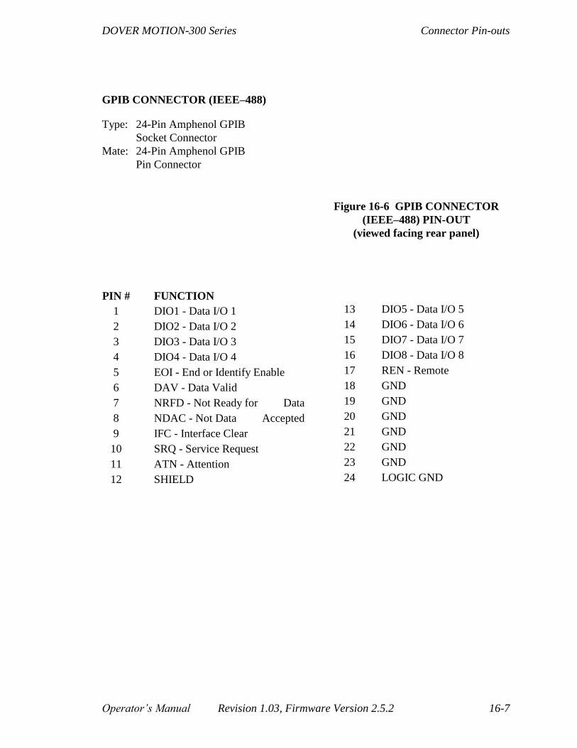
DOVER MOTION-300 Series Connector Pin-outs
Operator’s Manual Revision 1.03, Firmware Version 2.5.2 16-7
GPIB CONNECTOR (IEEE–488)
Type: 24-Pin Amphenol GPIB
Socket Connector
Mate: 24-Pin Amphenol GPIB
Pin Connector
Figure 16-6 GPIB CONNECTOR
(IEEE–488) PIN-OUT
(viewed facing rear panel)
PIN # FUNCTION
1 DIO1 - Data I/O 1
2 DIO2 - Data I/O 2
3 DIO3 - Data I/O 3
4 DIO4 - Data I/O 4
5 EOI - End or Identify Enable
6 DAV - Data Valid
7 NRFD - Not Ready for Data
8 NDAC - Not Data Accepted
9 IFC - Interface Clear
10 SRQ - Service Request
11 ATN - Attention
12 SHIELD
13 DIO5 - Data I/O 5
14 DIO6 - Data I/O 6
15 DIO7 - Data I/O 7
16 DIO8 - Data I/O 8
17 REN - Remote
18 GND
19 GND
20 GND
21 GND
22 GND
23 GND
24 LOGIC GND

Connector Pin-outs DOVER MOTION-300 Series
16-8 Revision 1.03, Firmware Version 2.5.2 Operator’s Manual
DOVER MOTION-300 Series Miscellaneous
Operator’s Manual Revision 1.03, Firmware Version 2.5.2 17-1
17. Miscellaneous
17.1. Mounting and Cooling Provisions
The DOVER MOTION–300 is designed to be mounted on a standard 19-inch rack. It must
be operated in ambient temperatures between 40 degrees F and 110 degrees F, with
humidity < 95% (non-condensing). The units storage temperature range is –20 degrees F to
+ 150 degrees F.
It provides its own cooling by means of a large heat sink and DC brushless fan. Air enters
via the plastic guard at the front left side of the unit, and exits at the rear. Accordingly,
enough room must be left between adjacent units to allow free passage of air.
The inlet guard incorporates a washable air filter to trap dust and contaminants. This may
be removed for cleaning by using a 078" allen wrench to remove the four #6–32 flathead
screws that hold the guard in place. Warning! To avoid the possibility of electrical
shock, the AC power cord must be removed before unscrewing the four screws
(turning the unit off is not enough). After removing the two piece plastic guard, it can
be snapped apart to allow the internal filter mesh to be cleaned.
17.2. Power Issues: Changing Fuses, and Converting to
230 Volt 50/60 Hz Operation
Changing fuses, and changing the line-voltage, involve very similar procedures. The
DOVER MOTION–300 Series has been designed to permit operation at both 115 and 230
volt AC line levels.
Japan uses a 100/200 volt system, which requires a supplemental transformer.
As far as we know, all other nations adhere to either the 110/115/120 or the
220/230/240 volt AC mains-supply standard.
The conversion—and fuse changing—is performed as follows:
1. Pop open the hinged cover on the AC line receptacle module, in the lower left corner
of the rear panel. This can be done by simply slipping a screw driver into the slot on
the far right and opening the cover.
2. You will see a red, plastic fuse holder assembly which can be removed by prying
gently on either its top or bottom.
To inspect or replace fuses, simply remove the assembly.
To change the line voltage setting, rotate the assembly 180 degrees before
reinstalling.

Miscellaneous DOVER MOTION-300 Series
17-2 Revision 1.03, Firmware Version 2.5.2 Operator’s Manual
3. Close the cover, confirming both the line voltage setting and that the AC power
switch is set to zero (off) before installing the AC cord.
4. The unit is now ready for operation; note, however, that a new power cord will be
required to interconnect the DOVER MOTION–300 rear panel universal IEC–
320/CEC–22 receptacle and the specific AC line outlet plate. Our sales department
can provide AC power cords to match the AC outlets of most industrialized countries.
The DOVER MOTION–300 will operate on either a 50 or 60 cycle AC supply, although
transformer heating will be somewhat greater at 50 Hz. The nominal 115/230 volt values
given above actually apply to either 110, 115, and 120 volt systems, or, when selected,
220, 230, and 240 volt systems. Proper operation is guaranteed over a standard +/- 10%
tolerance; accordingly, the voltage may not be less than 99 or more than 132 volts for a
115 volt selector switch setting, or less than 198 or more than 264 for a 230 volt switch
setting.

DOVER MOTION-300 Series Miscellaneous
Operator’s Manual Revision 1.03, Firmware Version 2.5.2 17-3
17.3. DOVER MOTION-300 Help Diskette
17.3.1. Diskette Contents
Each DOVER MOTION-300 is shipped with a 3.5” HELP diskette that contains a
number of utilities and example programs useful when interfacing the DOVER
MOTION-300 with a host computer. The HELP diskette is readable by IBM-PCs and
any other MS-DOS compatibles, and includes the following files:
NEAT.BAS NEAT.EXE
EX31.BAS EX31.EXE
EX32.BAS EX32.EXE
EX33.BAS EX33.EXE
EX35.BAS EX35.EXE
UP.BAS UP.EXE
DOWN.BAS DOWN.EXE
TEST.3X0
TEST1.3X0
TEST2.3X0
TEST3.3X0
READ.ME
The READ.ME file contains a listing of the files on the disk, with a brief description of
each, and some general comments. All files terminating in .BAS are commented source
code, written in Microsoft QuickBasic 4.5. While the specific instructions making up the
program are unique (to some degree) to this dialect of Basic, the underlying algorithms
should be portable to most other languages. The files terminating in .EXE are executable
files, and may be run simply by typing the filename (i.e., EX31 <ret">">).
The first file, NEAT.EXE, is a terminal emulator which reconfigures your PC as a
“dumb” terminal. Details on the operation of the emulator are given in Section 2.
Example programs 1 to 3, which cover computer interface techniques, are listed in full
and described in Section 5.
EX35 provides a typical implementation of “quasi-closed loop mode,” (see Encoder
Interface, Section 12), which provides servo-like performance from stepping motors. It is
listed below.
The remaining files are source and executable files of uploading and downloading
utilities, and are discussed in this section.

Miscellaneous DOVER MOTION-300 Series
17-4 Revision 1.03, Firmware Version 2.5.2 Operator’s Manual
17.3.1.1. EX35.BAS—Illustrates Quasi-Closed Loop
Operation
REM**********EX35.BAS...ILLUSTRATES "QUASI-CLOSED LOOP MODE"*************
IF COMMAND$ = "2" THEN 'ALLOW USER TO CHANGE COM PORT ON THE FLY
comprt$ = COMMAND$
ELSE
comprt$ = "1"
END IF
OPEN "COM" + comprt$ + ":9600,N,8,1,RS,CS,DS,CD" FOR RANDOM AS #1 LEN = 5000'OPEN SERIAL PORT
CLS 'CLEAR SCREEN
LOCATE 5, 1
PRINT "**********EX35.BAS...ILLUSTRATES QUASI-CLOSED LOOP MODE*************"
LOCATE 11, 20 'DISPLAY COM PORT SETUP
PRINT "COM" + comprt$ + ":9600,N,8,1,RS,CS,DS,CD FOR RANDOM AS #1 LEN = 5000"
PRINT #1, "TERM 3" 'SETUP NO ECHO TERMINAL MODE
GOSUB WAIT.PROMPT 'WAIT UNTIL ">" PROMPT IS RETURNED
LOCATE 11, 1
PRINT SPACE$(80); 'CLEAR DISPLAY
LOCATE 10, 20 'POSITION CURSOR
PRINT "MOVE STAGE TO CENTER POSITION" 'USER PROMPT
LOCATE 12, 23 'POSITION CURSOR
PRINT "TYPE ANY KEY WHEN READY" 'ASSURES STAGE IN CENTER OF TRAVEL
NULL$ = INPUT$(1) 'WAIT FOR KEYPRESS
ON KEY(1) GOSUB NEXT.POSITION 'FUNCTION KEY F1 GETS NEW POSITION
ON KEY(2) GOSUB END.PROGRAM 'FUNCTION KEY F2 ENDS PROGRAM
KEY(1) ON 'ENABLE F1 KEY
KEY(2) ON 'ENABLE F2 KEY
PRINT #1, "MFE" 'MAKE SURE MOVE FINISHED IS ENABLED
GOSUB WAIT.PROMPT 'AND WAIT FOR PROMPT
PRINT #1, "AX" 'SET FOR SINGLE-AXIS MODE
GOSUB WAIT.PROMPT 'AND WAIT FOR PROMPT
PRINT #1, "SE0" 'ZERO DOVER MOTION-3x0 ENCODER COUNTER HERE
GOSUB WAIT.PROMPT 'ETC.
CLS 'CLEAR SCREEN
LOCATE 20, 20 'POSITION CURSOR
PRINT "F1 FOR NEW POSITION, F2 TO END"; 'DISPLAY USER OPTIONS
MOVE: DO 'THIS ROUTINE "CLOSES THE LOOP"
NULL$ = INPUT$(LOC(1), #1) 'CLEAR THE SERIAL INPUT BUFFER
PRINT #1, "RE" 'SEND REPORT ENCODER COMMAND
INPUT #1, RESPONSE$ 'GET ENCODER POSITION
GOSUB WAIT.PROMPT 'WAIT UNTIL PROMPT RETURNS
LENGTH = LEN(RESPONSE$) 'FIND NUMBER OF RETURNED CHARACTERS
E.POS = INSTR(RESPONSE$, "E") 'FIND POSITION OF "E" (ECHO OF RE)
ENCODER& = VAL(RIGHT$(RESPONSE$, LENGTH - E.POS))'GET ENCODER POSITION
DIFF& = POSITION& - ENCODER& 'FIND DIFFERENCE OF DESIRED AND ACTUAL
LOCATE 5, 25 'POSITION CURSOR
PRINT USING "###.###"; ENCODER& / 1000 'DISPLAY REAL POSITION
PRINT #1, "MR" + STR$(DIFF&) 'SEND MOVE COMMAND EQUAL TO DIFFERENCE
GOSUB WAIT.STOPPED 'WAIT UNTIL MOVE IS COMPLETE
LOOP 'AND LOOP BACK

DOVER MOTION-300 Series Miscellaneous
Operator’s Manual Revision 1.03, Firmware Version 2.5.2 17-5
NEXT.POSITION: DO 'THIS ROUTINE GETS NEW POSITION
LOCATE 10, 20 'POSITION CURSOR
PRINT "ENTER NEW POSITION (-100.000 TO +100.000 mm.)"; 'PROMPT
LOCATE 12, 20 'POSITION CURSOR
PRINT "? "; 'DISPLAY QUESTION MARK
LINE INPUT POSITION$ 'GET DESIRED POSITION
LOCATE 10, 20 'REPOSITION CURSOR
PRINT SPACE$(60) 'BLANK PROMPT LINE
LOCATE 12, 20 'REPOSITION CURSOR
PRINT SPACE$(20); 'BLANK DESIRED POSITION
POSITION& = 1000 * VAL(POSITION$) 'CONVERT TO STEPS/COUNTS
POSITION& = INT(POSITION&) 'IN CASE USER ENTERED ADD'L DIGITS
LOOP UNTIL POSITION& >= -100000 AND POSITION& <= 100000 'CHECK
RETURN MOVE 'AND ENTER MOVE ROUTINE
WAIT.PROMPT: DO UNTIL INPUT$(1, #1) = ">" 'WAIT UNTIL 3x0 READY (SENDS ">")
LOOP 'LOOP PER ABOVE
RETURN 'EXIT SUBROUTINE
WAIT.STOPPED: DO UNTIL INPUT$(1, #1) = "F" 'WAIT UNTIL AN "F" ARRIVES
LOOP 'LOOP PER ABOVE
RETURN 'EXIT SUBROUTINE
END.PROGRAM: CLS
PRINT #1, "TERM 0" 'RESET ECHO TERMINAL MODE
GOSUB WAIT.PROMPT 'WAIT UNTIL ">" PROMPT IS RETURNED
CLOSE
END 'CLEAR SCREEN AND END PROGRAM
Miscellaneous DOVER MOTION-300 Series
17-6 Revision 1.03, Firmware Version 2.5.2 Operator’s Manual
17.3.2. UP.EXE and DOWN.EXE
The remaining files consist of the source and executable files of uploading and
downloading utilities mentioned in Running Programs (Section 9).
UP.EXE is an executable version of the program-upload utility. Upon typing UP <ret> ,
the screen will blank and the prompt: “ENTER NAME OF PROGRAM TO BE
UPLOADED” will appear. Enter the name of a program currently stored in the DOVER
MOTION-300’s internal memory (e.g., TEST <ret>). Assuming the program was
present, the screen will display the word “UPLOADING”, followed by “UPLOAD
COMPLETED AT LINE n”, where n is the number of statements in the program. The
screen will also display “TYPE ANY KEY TO EXIT TO DOS”; upon pressing any key,
the operating system prompt will appear. A DIR command will now reveal the DOVER
MOTION-300 program resident on disk, with a .300 file extension.
The downloader (DOWN.EXE) functions in virtually the same manner, except that the
number of the line being downloaded is displayed as it operates. With this utility, you
can use any convenient editor to create programs, store them on a disk, and download
them to the DOVER MOTION-300 as needed. This effectively unburdens the DOVER
MOTION-300’s internal memory.
Source code for the uploader and downloader follows, along with the sample program
TEST.300 that can be downloaded to demonstrate the process.

DOVER MOTION-300 Series Miscellaneous
Operator’s Manual Revision 1.03, Firmware Version 2.5.2 17-7
17.3.2.1. UP.BAS—Illustrates DOVER MOTION-300 to PC
Program Uploader
REM***************UP3.BAS...DOVER MOTION-3x0 TO PC PROGRAM UPLOADER
******************
IF COMMAND$ = "2" THEN 'ALLOW USER TO CHANGE COM PORT ON THE FLY
comprt$ = COMMAND$
ELSE
comprt$ = "1"
END IF
BEGIN: CLS 'CLEAR SCREEN
DIM PROG.ARRAY%(6000) 'PREPARE ARRAY TO RECEIVE PROGRAM
CTRLQ$ = CHR$(17) 'XON--RESUME FLOW CONTROL CHARACTER
CTRLS$ = CHR$(19) 'XOFF--PAUSE FLOW CONTROL CHARACTER
OPEN "COM" + comprt$ + ":9600,N,8,1,RS,CS,DS,CD" FOR RANDOM AS #1 LEN = 5000'OPEN SERIAL
PORT
ON ERROR GOTO ERRORHANDLER 'THIS TRAPS INVALID FILENAMES,ETC.
LOCATE 10, 20 'POSITION CURSOR
PRINT "INPUT NAME OF PROGRAM TO BE UPLOADED"; 'USER PROMPT
LOCATE 11, 20 'REPOSITION CURSOR
PRINT "? "; : LINE INPUT PROG.NAME$ 'GET PROGRAM NAME
CLS 'CLEAR SCREEN
LOCATE 11, 20 'DISPLAY COM PORT SETUP
PRINT "COM" + comprt$ + ":9600,N,8,1,RS,CS,DS,CD FOR RANDOM AS #1 LEN = 5000"
PRINT #1, "TERM 3" 'SETUP NO ECHO TERMINAL MODE
GOSUB WAIT.PROMPT 'WAIT UNTIL ">" PROMPT IS RETURNED
CLS 'CLEAR SCREEN
LOCATE 10, 20: PRINT "UPLOADING" 'MESSAGE WHILE UPLOADING
CHAR.NUM = 0 'INITIALIZE CHARACTER COUNTER
PRINT #1, "LPN " + PROG.NAME$ 'LIST DOVER MOTION-3x0 PROGRAM W/O LINE #'S
DO UNTIL CHARACTER$ = ">" 'UPLOAD LOOP; LOADS ARRAY WITH CHARACTERS
CHARACTER$ = INPUT$(1, #1) 'GRAB A CHARACTER FROM DOVER MOTION-3x0
PROG.ARRAY%(CHAR.NUM) = ASC(CHARACTER$) 'PUT IT IN THE ARRAY
CHAR.NUM = CHAR.NUM + 1 'INCREMENT CHARACTER POINTER
IF FLAG.OVF = 0 THEN
IF LOC(1) > 50 THEN 'IF CHARACTER BUFFER EXCEEDS 50
PRINT #1, CTRLS$; 'SEND CTRL-S TO PAUSE LISTING
FLAG.OVF = 1 'AND SET OVERFLOW FLAG
END IF
ELSE
IF LOC(1) < 10 THEN 'IF BUFFER SIZE LESS THAN 10
FLAG.OVF = 0 'RESET OVERFLOW FLAG
PRINT #1, CTRLQ$; 'SEND CTRL-Q TO RESUME LISTING
END IF
END IF
LOCATE 10, 20: PRINT "UPLOADING CHAR #"; CHAR.NUM 'DISPLAY
LOOP 'AND LOOP BACK
CHAR.NUM = 0 'RE-INITIALIZE CHARACTER COUNTER
LINE.NUM = 0 'INITIALIZE LINE COUNTER
DISK.NAME$ = PROG.NAME$ + ".3x0" 'APPEND FILE TYPE ".3x0" FOR DISK STORAGE
OPEN DISK.NAME$ FOR OUTPUT AS #2 'OPEN DISK FILE FOR WRITES
CHARACTER$ = "" 'NULL CHARACTER$ (IT'S ">" FROM LAST LOOP)
DO UNTIL CHARACTER$ = ">" 'DISK STORAGE LOOP

Miscellaneous DOVER MOTION-300 Series
17-8 Revision 1.03, Firmware Version 2.5.2 Operator’s Manual
CHARACTER$ = "" 'NULL CHARACTER$
LINE$ = "" 'NULL LINE$
DO UNTIL CHARACTER$ = CHR$(10) OR CHARACTER$ = ">" 'TEST FOR LF OR END
CHARACTER$ = CHR$(PROG.ARRAY%(CHAR.NUM)) 'RETRIEVE FROM ARRAY
IF CHARACTER$ <> CHR$(13) THEN 'STRIP CR's
IF CHARACTER$ <> CHR$(10) THEN 'STRIP LF's
IF CHARACTER$ <> ">" THEN 'STRIP >'s
LINE$ = LINE$ + CHARACTER$
END IF
END IF
END IF
CHAR.NUM = CHAR.NUM + 1 'INCREMENT CHARACTER COUNTER
LOOP 'AND LOOP BACK
PRINT #2, LINE$ 'SEND THE RESULT TO DISK
LINE.NUM = LINE.NUM + 1 'INCREMENT LINE.NUM
LOOP
PRINT #1, "TERM 0" 'RESET TO ECHO TERMINAL MODE
GOSUB WAIT.PROMPT 'WAIT UNTIL ">" PROMPT IS RETURNED
CLOSE #1 'CLOSE SERIAL PORT
CLOSE #2 'CLOSE DISK FILE
CLS 'CLEAR SCREEN
LOCATE 10, 20: PRINT "UPLOAD COMPLETED AT LINE "; LINE.NUM 'LET USER KNOW
LOCATE 12, 20: PRINT "TYPE ANY KEY TO EXIT TO DOS" 'EXIT PROMPT
NULL$ = INPUT$(1) 'WAIT FOR KEY-PRESS
CLS 'CLEAR SCREEN
END 'MAIN PROGRAM COMPLETE
WAIT.PROMPT: DO UNTIL INPUT$(1, #1) = ">" 'WAIT FOR PROMPT TO
LOOP 'RETURN (DOVER MOTION-3x0 READY)
RETURN
ERRORHANDLER: CLOSE #1 'IF INVALID FILE NAME,
CLOSE #2 'OR ANY OTHER ERROR
PRINT "ERROR, # ="; ERR: A$ = INPUT$(1)
RESUME BEGIN 'START OVER

DOVER MOTION-300 Series Miscellaneous
Operator’s Manual Revision 1.03, Firmware Version 2.5.2 17-9
17.3.2.2. DOWN.BAS—Illustrates PC to DOVER MOTION-
300
Program Downloader
REM*************DOWN3.BAS...PC TO DOVER MOTION-3x0 PROGRAM DOWNLOADER
***************
IF COMMAND$ = "2" THEN 'ALLOW USER TO CHANGE COM PORT ON THE FLY
comprt$ = COMMAND$
ELSE
comprt$ = "1"
END IF
ON ERROR GOTO ERRORHANDLER 'THIS TRAPS INVALID FILE NAMES, ETC.
BEGIN: CLS 'CLEAR SCREEN OPEN "COM" + comprt$ + ":9600,N,8,1,RS,CS,DS,CD" FOR RANDOM AS #1 LEN = 5000'OPEN SERIAL PORT
LOCATE 10, 20 'POSITION CURSOR
PRINT "INPUT NAME OF PROGRAM TO BE DOWNLOADED"; 'USER PROMPT
LOCATE 11, 20 'REPOSITION CURSOR
PRINT "? "; : LINE INPUT PROG.NAME$ 'GET PROGRAM NAME
CLS 'CLEAR SCREEN
LOCATE 11, 20 'DISPLAY COM PORT SETUP
PRINT "COM" + comprt$ + ":9600,N,8,1,RS,CS,DS,CD FOR RANDOM AS #1 LEN = 5000"
PRINT #1, CHR$(27) 'SEND <Esc> TO CLEAR UNIT
GOSUB WAIT.PROMPT 'WAIT UNTIL ">" PROMPT IS RETURNED
GOSUB CLEAR.INPUT 'CLEAR OUT ANY EXTRA INPUT
PRINT #1, "TERM 3" 'SETUP NO ECHO TERMINAL MODE
GOSUB WAIT.PROMPT 'WAIT UNTIL ">" PROMPT IS RETURNED
LOCATE 11, 1 'CLEAR LINE
PRINT SPACE$(80);
PRINT #1, "KP " + PROG.NAME$ 'KILL ANY EXISTING PROGRAM OF SAME NAME
GOSUB WAIT.PROMPT 'WAIT FOR PROMPT
DISK.NAME$ = PROG.NAME$ + ".3x0" 'APPEND ".3x0" FILE TYPE FOR DISK ACCESS
OPEN DISK.NAME$ FOR INPUT AS #2 'OPEN DISK FILE FOR READS
PRINT #1, "EP " + PROG.NAME$ 'BEGIN DOVER MOTION-3x0 EDIT
GOSUB WAIT.SPACE 'WAIT FOR SPACE (3x0 READY FOR CMD LINE)
ON ERROR GOTO ERRORHANDLER2 'THIS TRAPS ERRORS
LINE.NUM = 0 'INITIALIZE LINE COUNTER
DO UNTIL EOF(2) 'MAIN DOWNLOADING LOOP; CONTINUES UNTIL DISK FILE FINISHED
LINE INPUT #2, PROG.LINE$ 'READ COMMAND LINE FROM DISK FILE
GOSUB CHECK.REAL 'MAKE SURE LINE HAS VALID ASCII DATA
IF REAL THEN
PRINT #1, PROG.LINE$ 'SEND COMMAND
GOSUB WAIT.SPACE 'WAIT UNTIL READY FOR NEXT LINE
LINE.NUM = LINE.NUM + 1 'INCREMENT LINE COUNTER
END IF
LOCATE 10, 20: PRINT "DOWNLOADING LINE #"; LINE.NUM 'DISPLAY LINE#
LOOP 'AND LOOP BACK
EXRESUME: 'RESUME FROM ERRORHANDLER2
CLOSE #2 'CLOSE THE DISK FILE
PRINT #1, CHR$(27) 'SEND ESCAPE TO TERMINATE DOVER MOTION-3x0 EDIT
GOSUB WAIT.PROMPT 'WAIT UNTIL ">" PROMPT IS RETURNED
PRINT #1, "TERM 0" 'RESET ECHO TERMINAL MODE
GOSUB WAIT.PROMPT 'WAIT UNTIL ">" PROMPT IS RETURNED

Miscellaneous DOVER MOTION-300 Series
17-10 Revision 1.03, Firmware Version 2.5.2 Operator’s Manual
LOCATE 10, 20 'POSITION CURSOR
PRINT "DOWNLOAD COMPLETED AT LINE "; LINE.NUM 'LET USER KNOW
LOCATE 12, 20 'REPOSITION CURSOR
PRINT "TYPE ANY KEY TO EXIT TO DOS" 'EXIT PROMPT
NULL$ = INPUT$(1) 'WAIT FOR KEY-PRESS
CLS 'CLEAR SCREEN
CLOSE #1 'CLOSE SERIAL PORT
END 'END PROGRAM
WAIT.PROMPT: DO UNTIL INPUT$(1, #1) = ">" 'THIS ROUTINE WAITS UNTIL THE
LOOP 'DOVER MOTION-3x0 SENDS A CARRIAGE
RETURN 'RETURN (DOVER MOTION-3x0 READY)
WAIT.SPACE: DO 'SKIP CHARS UNTIL LINE # FOUND
A$ = INPUT$(1, #1)
LOOP UNTIL A$ >= "0" AND A$ <= "9"
DO 'SKIP LINE # CHARACTERS
A$ = INPUT$(1, #1)
LOOP WHILE A$ >= "0" AND A$ <= "9" 'UNTIL 1ST SPACE FOUND
A$ = INPUT$(1, #1) 'SKIP 2ND SPACE AFTER LINE #
RETURN
CHECK.REAL: REAL = 0 'THIS ROUTINE CHECKS THAT THE COMMAND LINE
FOR I = 1 TO LEN(PROG.LINE$) 'HAS VALID CHARACTERS
IF ASC(MID$(PROG.LINE$, I, 1)) > 32 THEN REAL = 1
NEXT I
RETURN
CLEAR.INPUT: DO WHILE LOC(1) > 0 'WHILE CHARS IN BUFFER
A$ = INPUT$(1, #1) 'READ THEM IN
LOOP
RETURN
ERRORHANDLER: CLOSE #1: CLOSE #2 'TRY AGAIN IF FILE NOT FOUND,
RESUME BEGIN 'OR OTHER ERROR
ERRORHANDLER2: PRINT "ERROR DURING DOWNLOAD"
RESUME EXRESUME 'OR OTHER ERROR
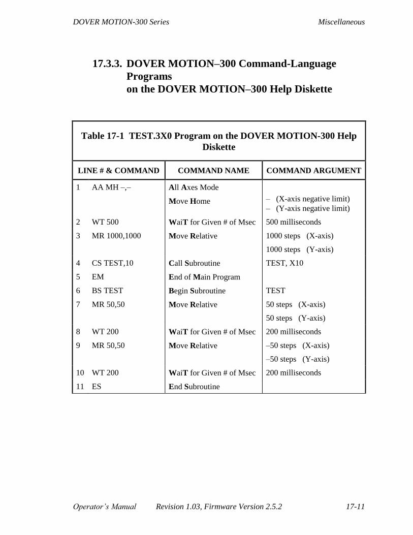
DOVER MOTION-300 Series Miscellaneous
Operator’s Manual Revision 1.03, Firmware Version 2.5.2 17-11
17.3.3. DOVER MOTION–300 Command-Language
Programs
on the DOVER MOTION–300 Help Diskette
Table 17-1 TEST.3X0 Program on the DOVER MOTION-300 Help
Diskette
LINE # & COMMAND COMMAND NAME COMMAND ARGUMENT
1 AA MH –,– All Axes Mode
Move Home
– (X-axis negative limit)
– (Y-axis negative limit)
2 WT 500 WaiT for Given # of Msec 500 milliseconds
3 MR 1000,1000 Move Relative 1000 steps (X-axis)
1000 steps (Y-axis)
4 CS TEST,10 Call Subroutine TEST, X10
5 EM End of Main Program
6 BS TEST Begin Subroutine TEST
7 MR 50,50 Move Relative 50 steps (X-axis)
50 steps (Y-axis)
8 WT 200 WaiT for Given # of Msec 200 milliseconds
9 MR 50,50 Move Relative –50 steps (X-axis)
–50 steps (Y-axis)
10 WT 200 WaiT for Given # of Msec 200 milliseconds
11 ES End Subroutine

Miscellaneous DOVER MOTION-300 Series
17-12 Revision 1.03, Firmware Version 2.5.2 Operator’s Manual
Table 17-2 TEST1.3X0 Program on the DOVER MOTION-300 Help
Diskette
LINE # & COMMAND COMMAND NAME COMMAND ARGUMENT
1 MH 0 Move Home 0 (X-axis negative limit)
2 WT 1000 WaiT for Given # of Msec 1000 milliseconds
3 RP Report Position
4 RE Report Encoder
5 MA 10000 Move Absolute To position 10,000 (X-axis)
6 WT 500 WaiT for Given # of Msec 500 milliseconds
7 RP Report Position
8 RE Report Encoder
9 MA 0 Move Absolute To position 0 (X-axis)
10 JP 2 JumP to line 2

DOVER MOTION-300 Series Miscellaneous
Operator’s Manual Revision 1.03, Firmware Version 2.5.2 17-13
Table 17-3 TEST2.3X0 Program on the DOVER MOTION-300 Help
Diskette
LINE # & COMMAND COMMAND NAME COMMAND ARGUMENT
1 MH 0,0 Move Home 0 (X-axis negative limit)
0 Y-axis negative limit)
2 WT 1000 WaiT for Given # of Msec 1000 milliseconds
3 RP Report Position
4 RE Report Encoder
5 MA 10000,10000 Move Absolute To position 10,000 (X-axis)
10,000 (Y-axis)
6 WT 500 WaiT for Given # of Msec 500 milliseconds
7 RP Report Position
8 RE Report Encoder
9 MA 0,0 Move Absolute To position 0 (X-axis)
0 (Y-axis)
10 JP 2 JumP to line 2
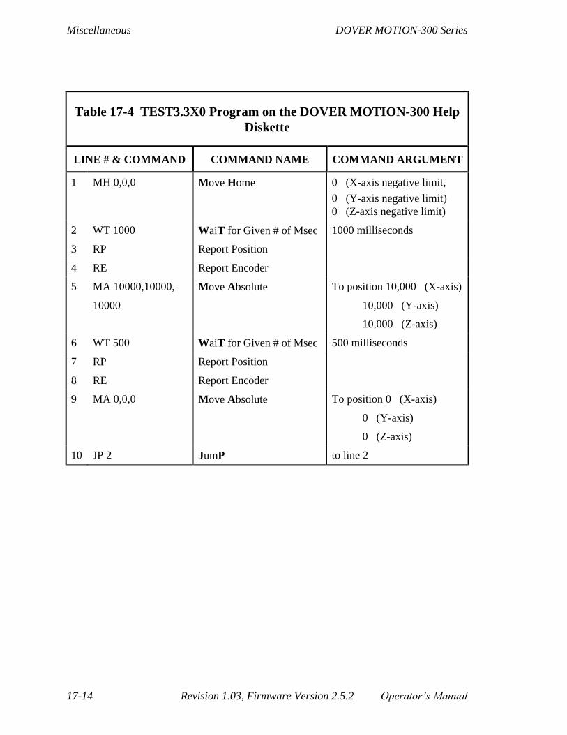
Miscellaneous DOVER MOTION-300 Series
17-14 Revision 1.03, Firmware Version 2.5.2 Operator’s Manual
Table 17-4 TEST3.3X0 Program on the DOVER MOTION-300 Help
Diskette
LINE # & COMMAND COMMAND NAME COMMAND ARGUMENT
1 MH 0,0,0 Move Home 0 (X-axis negative limit,
0 (Y-axis negative limit)
0 (Z-axis negative limit)
2 WT 1000 WaiT for Given # of Msec 1000 milliseconds
3 RP Report Position
4 RE Report Encoder
5 MA 10000,10000,
10000
Move Absolute To position 10,000 (X-axis)
10,000 (Y-axis)
10,000 (Z-axis)
6 WT 500 WaiT for Given # of Msec 500 milliseconds
7 RP Report Position
8 RE Report Encoder
9 MA 0,0,0 Move Absolute To position 0 (X-axis)
0 (Y-axis)
0 (Z-axis)
10 JP 2 JumP to line 2

DOVER MOTION-300 Series Miscellaneous
Operator’s Manual Revision 1.03, Firmware Version 2.5.2 17-15
17.4. Bit-Mask Value Table
In Section 7.1 we presented the concept of bit-masks—single numbers that the DOVER
MOTION-300 uses to represent sets of values in both command parameters and command
reports.
Table 17-5 allows you to look up a reported mask value from 0 to 255 and see what
selection of eight entities numbered 0 through 7 is represented by the mask value.
When a DOVER MOTION-300 command uses mask values either as
parameters or in reports it usually uses them to represent entities that are
counted from zero—for example, as discussed in Section 7.1, the eight digital
I/O inputs from DI0 to DI7. (The exception is joysticks, but here there are
only four numbers to be represented, so the mask value never exceeds 15
(=1+2+4+8) and so is easy to decipher.) Therefore, in the table, we have
shown what selection of eight numbers from 0 to 7 is represented by each
mask value.

Miscellaneous DOVER MOTION-300 Series
17-16 Revision 1.03, Firmware Version 2.5.2 Operator’s Manual
Table 17-5 Bit-Mask Values Representing Eight Numbers — Page 1
Mask
Value
Numbers Represented
(Selected from 0, 1, 2, 3, 4, 5, 6, 7)
Mask
Value
Numbers Represented
(Selected from 0, 1, 2, 3, 4, 5, 6, 7)
0 43 0 1 3 5
1 0 44 2 3 5
2 1 45 0 2 3 5
3 0 1 46 1 2 3 5
4 2 47 0 1 2 3 5
5 0 2 48 4 5
6 1 2 49 0 4 5
7 0 1 2 50 1 4 5
8 3 51 0 1 4 5
9 0 3 52 2 4 5
10 1 3 53 0 2 4 5
11 0 1 3 54 1 2 4 5
12 2 3 55 0 1 2 4 5
13 0 2 3 56 3 4 5
14 1 2 3 57 0 3 4 5
15 0 1 2 3 58 1 3 4 5
16 4 59 0 1 3 4 5
17 0 4 60 2 3 4 5
18 1 4 61 0 2 3 4 5
19 0 1 4 62 1 2 3 4 5
20 2 4 63 0 1 2 3 4 5
21 0 2 4 64 6
22 1 2 4 65 0 6
23 0 1 2 4 66 1 6
24 3 4 67 0 1 6
25 0 3 4 68 2 6
26 1 3 4 69 0 2 6
27 0 1 3 4 70 1 2 6
28 2 3 4 71 0 1 2 6
29 0 2 3 4 72 3 6
30 1 2 3 4 73 0 3 6
31 0 1 2 3 4 74 1 3 6
32 5 75 0 1 3 6
33 0 5 76 2 3 6
34 1 5 77 0 2 3 6
35 0 1 5 78 1 2 3 6
36 2 5 79 0 1 2 3 6
37 0 2 5 80 4 6
38 1 2 5 81 0 4 6
39 0 1 2 5 82 1 4 6
40 3 5 83 0 1 4 6
41 0 3 5 84 2 4 6
42 1 3 5 85 0 2 4 6

DOVER MOTION-300 Series Miscellaneous
Operator’s Manual Revision 1.03, Firmware Version 2.5.2 17-17
Bit-Mask Values: Representing Eight Numbers — Page 2
Mask
Value
Numbers Represented
(Selected from 0, 1, 2, 3, 4, 5, 6, 7)
Mask
Value
Numbers Represented
(Selected from 0, 1, 2, 3, 4, 5, 6, 7)
86 1 2 4 6 128 7
87 0 1 2 4 6 129 0 7
88 3 4 6 130 1 7
89 0 3 4 6 131 0 1 7
90 1 3 4 6 132 2 7
91 0 1 3 4 6 133 0 2 7
92 2 3 4 6 134 1 2 7
93 0 2 3 4 6 135 0 1 2 7
94 1 2 3 4 6 136 3 7
95 0 1 2 3 4 6 137 0 3 7
96 5 6 138 1 3 7
97 0 5 6 139 0 1 3 7
98 1 5 6 140 2 3 7
99 0 1 5 6 141 0 2 3 7
100 2 5 6 142 1 2 3 7
101 0 2 5 6 143 0 1 2 3 7
102 1 2 5 6 144 4 7
103 0 1 2 5 6 145 0 4 7
104 3 5 6 146 1 4 7
105 0 3 5 6 147 0 1 4 7
106 1 3 5 6 148 2 4 7
107 0 1 3 5 6 149 0 2 4 7
108 2 3 5 6 150 1 2 4 7
109 0 2 3 5 6 151 0 1 2 4 7
110 1 2 3 5 6 152 3 4 7
111 0 1 2 3 5 6 153 0 3 4 7
112 4 5 6 154 1 3 4 7
113 0 4 5 6 155 0 1 3 4 7
114 1 4 5 6 156 2 3 4 7
115 0 1 4 5 6 157 0 2 3 4 7
116 2 4 5 6 158 1 2 3 4 7
117 0 2 4 5 6 159 0 1 2 3 4 7
118 1 2 4 5 6 160 5 7
119 0 1 2 4 5 6 161 0 5 7
120 3 4 5 6 162 1 5 7
121 0 3 4 5 6 163 0 1 5 7
122 1 3 4 5 6 164 2 5 7
123 0 1 3 4 5 6 165 0 2 5 7
124 2 3 4 5 6 166 1 2 5 7
125 0 2 3 4 5 6 167 0 1 2 5 7
126 1 2 3 4 5 6 168 3 5 7
127 0 1 2 3 4 5 6 169 0 3 5 7
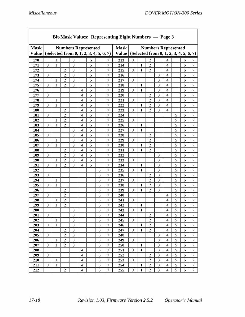
Miscellaneous DOVER MOTION-300 Series
17-18 Revision 1.03, Firmware Version 2.5.2 Operator’s Manual
Bit-Mask Values: Representing Eight Numbers — Page 3
Mask
Value
Numbers Represented
(Selected from 0, 1, 2, 3, 4, 5, 6, 7)
Mask
Value
Numbers Represented
(Selected from 0, 1, 2, 3, 4, 5, 6, 7)
170 1 3 5 7 213 0 2 4 6 7
171 0 1 3 5 7 214 1 2 4 6 7
172 2 3 5 7 215 0 1 2 4 6 7
173 0 2 3 5 7 216 3 4 6 7
174 1 2 3 5 7 217 0 3 4 6 7
175 0 1 2 3 5 7 218 1 3 4 6 7
176 4 5 7 219 0 1 3 4 6 7
177 0 4 5 7 220 2 3 4 6 7
178 1 4 5 7 221 0 2 3 4 6 7
179 0 1 4 5 7 222 1 2 3 4 6 7
180 2 4 5 7 223 0 1 2 3 4 6 7
181 0 2 4 5 7 224 5 6 7
182 1 2 4 5 7 225 0 5 6 7
183 0 1 2 4 5 7 226 1 5 6 7
184 3 4 5 7 227 0 1 5 6 7
185 0 3 4 5 7 228 2 5 6 7
186 1 3 4 5 7 229 0 2 5 6 7
187 0 1 3 4 5 7 230 1 2 5 6 7
188 2 3 4 5 7 231 0 1 2 5 6 7
189 0 2 3 4 5 7 232 3 5 6 7
190 1 2 3 4 5 7 233 0 3 5 6 7
191 0 1 2 3 4 5 7 234 1 3 5 6 7
192 6 7 235 0 1 3 5 6 7
193 0 6 7 236 2 3 5 6 7
194 1 6 7 237 0 2 3 5 6 7
195 0 1 6 7 238 1 2 3 5 6 7
196 2 6 7 239 0 1 2 3 5 6 7
197 0 2 6 7 240 4 5 6 7
198 1 2 6 7 241 0 4 5 6 7
199 0 1 2 6 7 242 1 4 5 6 7
200 3 6 7 243 0 1 4 5 6 7
201 0 3 6 7 244 2 4 5 6 7
202 1 3 6 7 245 0 2 4 5 6 7
203 0 1 3 6 7 246 1 2 4 5 6 7
204 2 3 6 7 247 0 1 2 4 5 6 7
205 0 2 3 6 7 248 3 4 5 6 7
206 1 2 3 6 7 249 0 3 4 5 6 7
207 0 1 2 3 6 7 250 1 3 4 5 6 7
208 4 6 7 251 0 1 3 4 5 6 7
209 0 4 6 7 252 2 3 4 5 6 7
210 1 4 6 7 253 0 2 3 4 5 6 7
211 0 1 4 6 7 254 1 2 3 4 5 6 7
212 2 4 6 7 255 0 1 2 3 4 5 6 7

DOVER MOTION-300 Series Miscellaneous
Operator’s Manual Revision 1.03, Firmware Version 2.5.2 17-19
17.5. Motion Calculations
The DOVER MOTION-300 command set allows position, velocity, and
acceleration/deceleration values to be entered directly (in steps, steps/sec., and
steps/sec/sec, respectively), without cumbersome formulas relating entered values to
actual performance. In some cases, users may need to calculate the time necessary to
perform a move, or determine the distance required to reach top speed. The following
should help in solving these types of problems.
To calculate the time necessary to make a given move, we must first determine if the
move was large enough to allow the motor to reach the top speed. This amounts to
checking if the move is larger than the sum of the acceleration distance plus the
deceleration distance. (We are speaking here not of the actual acceleration and
deceleration distances for this particular move, but rather of what these distances would
be if the move were long enough to accommodate acceleration to the specified final
velocity. Likewise, “Velocity Final” in this sum refers to the specified Velocity Final.
These “ideal” values will equal the actual values in a particular move only if the move is
long enough.) This sum equals:
(Velocity Final - Velocity Initial)
Acceleration 2 +
(Velocity Final - Velocity Initial)
Deceleration 2
2 2
For example let’s assume that the acceleration and deceleration are both set to 8,000
steps/sec/sec, that the Velocity Initial is equal to 500 steps/sec, and the Velocity Final is
4500 steps/sec. The distance over which the motor will accelerate is then:
(4,500 - 500)
8,000 2 =
16,000,000
16,000 1,000 steps
2
Since the acceleration and deceleration are equal in this example, their sum is 1000 +
1000 = 2000 steps. If the move distance equals or exceeds 2000 steps, the top speed will
be achieved; moves less than 2000 steps long will not reach the programmed top speed.
The time spent during acceleration or deceleration equals:
Velocity Final - Velocity Initial
Acceleration (or Deceleration)

Miscellaneous DOVER MOTION-300 Series
17-20 Revision 1.03, Firmware Version 2.5.2 Operator’s Manual
In the previous example, the motor would spend 4 500 500
8 00050 seconds
, -
, = .
accelerating and the same decelerating. If the move was exactly 2000 steps long, it would
take exactly 1.00 second (.50 + .50) from start to stop. For longer moves, the time spent
traveling at Velocity Final must be added, so the total time would equal:
Accel. Time + Decel. Time +
Move Distance - (Accel. Distance + Decel. Distance)
Velocity Final
For a 10000 step move, the overall time will be:
.50 + .50 + 10,000 - (1,000 + 1,000)
4,500 = 2.78 seconds
The case of moves which are too short to reach top speed is only slightly more complex.
The simplest case is that for which the acceleration and deceleration are equal. The peak
velocity will then occur at the halfway point. In the case of a 1000-step move with the
previous values, the motor will accelerate for 500 steps and decelerate for 500 steps. The
acceleration time is then:
2 x Accel . Distance
Acceleration , or
2 x 500
8,000
which equals .354 seconds. The overall move is then .354 + .354, or .708 seconds. In
cases where the acceleration and deceleration are set to different values, the relative
accel/decel. distances are simply scaled accordingly. For example, if the deceleration was
set to 16,000 steps/sec/sec. or twice the acceleration value, then the accel. distance is
equal to:
Move Distance x (Deceleration)
(Acceleration & Deceleration)
or 1,000 x 16,000
(8,000 + 16,000) = 667 steps

DOVER MOTION-300 Series Miscellaneous
Operator’s Manual Revision 1.03, Firmware Version 2.5.2 17-21
The deceleration distance is similarly equal to:
Move Distance x (Acceleration)
(Acceleration & Deceleration)
or 1,000 x 8,000
(8,000 + 16,000) = 333 steps
The acceleration distance increases with the deceleration, and visa versa.
Why is that? Both phases (acceleration and deceleration) must accomplish the
same velocity change (though in different directions). In both phases the rate
of change of velocity is constant, so the average velocity is the same for both
phases. The distance for each phase is therefore directly proportional to the
time. Since both phases must accomplish the same velocity change, the one
with the higher rate of velocity change will accomplish it in less time. Thus
acceleration distance increases with deceleration, and visa versa.
Having found the accel./decel. distances, the times are found, as before, by:
2 x Accel. distance
Acceleration +
2 x Decel. distance
Deceleration=
1,334
8,000 +
666
16,000
= .408 + .204 = .612 seconds
The top speed reached is found with the following formula:
Velocity Final = Velocity Initial + (Acceleration x Accel. time)
= 500 + (8,000 x .408) = 3,764 steps/second

Miscellaneous DOVER MOTION-300 Series
17-22 Revision 1.03, Firmware Version 2.5.2 Operator’s Manual
17.6. Return Procedures
Please follow the following procedures when returning equipment.
1. Please Call (Or Fax) Customer Service First
DOVER MOTION provides over-the-phone technical assistance which can, in many
cases, resolve any problem(s) you may be having. We require that you contact our
Customer Service Department before returning any equipment for repair. Our phone and
fax numbers are:
Phone: 508-475-3400
Email: [email protected]
2. Request a Return Authorization (RA) Number
If, after speaking with a Customer Service Technician, it is determined that you will need
to return the equipment for repairs, request a Return Authorization (RA) number.
NOTE: THIS NUMBER IS MANDATORY FOR ALL REPAIRS
3. Fill out the enclosed CUSTOMER RETURN FORM. Include your
purchase order (PO) number and a contact name.
Before shipping any equipment to DOVER MOTION for repair, please fill out the
enclosed Customer Return Form. Please make sure that the mandatory Return
Authorization and Purchase Order numbers are supplied as well as a complete, detailed
description of the problem(s) with the equipment. DOVER MOTION will provide an
estimate before charging any dollar amount to the issued Purchase Order number. When
the estimate has been accepted by written confirmation, DOVER MOTION will proceed
with repairing the equipment.
NOTE: PLEASE FOLLOW ALL RETURN SHIPPING
PROCEDURES OUTLINED ON THE NEXT PAGE

DOVER MOTION-300 Series Miscellaneous
Operator’s Manual Revision 1.03, Firmware Version 2.5.2 17-23
4. Turnaround Times
For all repairs covered under Warranty, the typical turnaround time is 48 hours from the
receipt of the equipment at DOVER MOTION’s facility. For repairs not covered under
warranty, a typical turnaround time of two weeks can be expected depending on the type
of work required to repair the system and on the Customer Service Department’s
schedule. Please do not hesitate to call if you have any questions about the status of your
in-house repair.
5. Documentation
Once the repair has been completed, you will receive a Customer Repair Report complete
with a description of the parts and labor needed to repair the equipment. For repairs
covered under Warranty, a no-charge invoice will be included for your records. For
repairs not covered under Warranty, an invoice, referencing the Purchase Order number
issued, will be forwarded to your Accounts Payable department. The equipment will then
be shipped to the address given on the Customer Return Form.
17.7. Packaging and Shipping
NOTE: THIS EQUIPMENT HAS BEEN PACKAGED
CAREFULLY. THE FOLLOWING PROCEDURES
MUST BE FOLLOWED WHEN RETURNING
EQUIPMENT.
1. Packaging
The DOVER MOTION 300 must be returned in its original packaging. If you don't have
it, DOVER MOTION will ship you one at a modest charge.
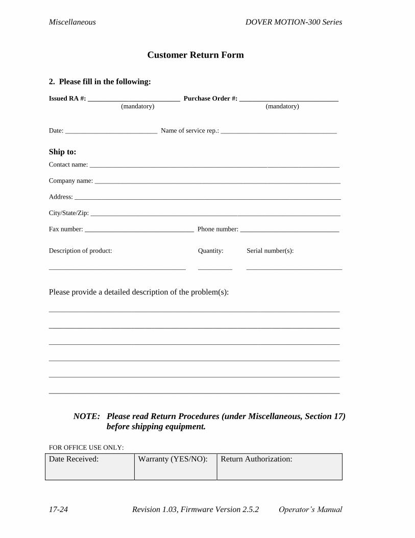
Miscellaneous DOVER MOTION-300 Series
17-24 Revision 1.03, Firmware Version 2.5.2 Operator’s Manual
Customer Return Form
2. Please fill in the following:
Issued RA #: ___________________________ Purchase Order #: _____________________________
(mandatory) (mandatory)
Date: ___________________________ Name of service rep.: __________________________________
Ship to:
Contact name: _________________________________________________________________________
Company name: ________________________________________________________________________
Address: ______________________________________________________________________________
City/State/Zip: _________________________________________________________________________
Fax number: ________________________________ Phone number: _____________________________
Description of product: Quantity: Serial number(s):
________________________________________ __________ ____________________________
Please provide a detailed description of the problem(s):
_____________________________________________________________________________________
_____________________________________________________________________________________
_____________________________________________________________________________________
_____________________________________________________________________________________
_____________________________________________________________________________________
_____________________________________________________________________________________
NOTE: Please read Return Procedures (under Miscellaneous, Section 17)
before shipping equipment.
FOR OFFICE USE ONLY:
Date Received: Warranty (YES/NO): Return Authorization:

DOVER MOTION-300 Series Miscellaneous
Operator’s Manual Revision 1.03, Firmware Version 2.5.2 17-25
17.8. Terms and Conditions
DOVER MOTION warrants to original equipment manufacturers, distributors and industrial and
commercial users of its products that each new product manufactured or supplied by DOVER MOTION
shall be free from defects in materials and workmanship. DOVER MOTION’s sole obligation under this
warranty is limited to furnishing without additional charge a replacement for, or at its option, repairing or
issuing credit for any product which shall within one year from the date of sale by DOVER MOTION be
returned freight prepaid to the plant designated by DOVER MOTION and which upon inspection is
determined by DOVER MOTION to be defective in materials or workmanship. Complete information as to
operating conditions and machine set-up must accompany any product returned for inspection. The
provisions of this warranty shall not apply to any DOVER MOTION product which has been subjected to
misuse, improper operating conditions, machine set-up, or which has been repaired or altered. Seller makes
no warranty that its products are fit for the use or purpose to which they may be put by the buyer, whether
or not such use or purpose has been disclosed to seller in specifications or drawings previously or
subsequently provided seller, and whether or not seller’s products are specifically designed and/or
manufactured for this purpose. THIS WARRANTY IS IN LIEU OF ALL OTHER WARRANTIES,
EXPRESSED OR IMPLIED, INCLUDING ANY IMPLIED WARRANTY OF MERCHANTABILITY
OR FITNESS FOR A PARTICULAR PURPOSE. DOVER MOTION’s sole liability on any such claim of
any kind, whether in contract, tort or otherwise, for any loss or damage arising out of, connected with, or
resulting from the manufacture, sale, delivery or use of the products sold thereunder shall in no case exceed
the cost of replacement or repair as provided herein. IN NO EVENT SHALL DOVER MOTION BE
LIABLE FOR ANY SPECIAL, INCIDENTAL OR CONSEQUENTIAL DAMAGES. There are no other
warranties, expressed or implied, made by DOVER MOTION except the warranty against defects in
materials and workmanship set forth above and neither assumes nor authorizes any other person or firm to
assume for it any other obligations or liability in connection with its products.
Upon written request, custom design work performed by DOVER MOTION will be subject to engineering
charges. Payments are due upon acceptance of the custom design work. DOVER MOTION will retain all
copyright and other proprietary rights to the product and any additional custom work. The Purchaser shall
respect the proprietary rights of DOVER MOTION and shall take measures to prevent unauthorized
disclosure of information relating to the product and any additional custom design work. DOVER
MOTION shall retain all proprietary rights and shall have the right and authority to use, sell, market,
research, and utilize for any other purpose at its sole discretion said product and custom design work
without notification or any liability whatsoever, including but not limited to monetary remuneration, to the
Purchaser.
2. Returning Goods Policy
Claims for incorrect or defective materials must be received in writing within thirty (30) days from delivery
at buyer’s place of business. No units or systems may be returned, in or out of warranty, without first
issuing a purchase order and obtaining a return authorization number from the seller, and no claim will be
allowed nor credit given for units or systems returned without such approval. After approval from DOVER
MOTION the defective unit or system is to be returned to the factory with a written statement of the
problem and transportation prepaid (no C.O.D. or collect freight shipments will be accepted). After
DOVER MOTION’s in-plant examination, warranty or out-of-warranty status will be determined. If upon
examination of such unit or system, warranteed defects exist, then the unit or system will be repaired at no
charge and shipped prepaid back to the buyer, via common carrier. If an out-of-warranty situation exists,
the buyer shall be notified of the repair cost immediately. At such time, the buyer must issue a purchase
order to cover the cost of the repair or authorize the unit or system to be shipped back as is, at the buyer’s
cost.

Miscellaneous DOVER MOTION-300 Series
17-26 Revision 1.03, Firmware Version 2.5.2 Operator’s Manual
2. Field Service Policy
If the system or unit cannot be made functional by no-charge telephone assistant or purchased replacement
parts, and cannot be returned to the DOVER MOTION factory for repair, then the following field service
policy will apply: DOVER MOTION will provide an on-site field service representative in a reasonable
amount of time, provided that the customer issues a bonafide purchase order to DOVER MOTION covering
all transportation and subsistence costs and the prevailing cost per hour (eight hour minimum) including
travel time necessary to complete the repair, regardless of warranty determination. If the DOVER
MOTION field service representative determines during his on-site repair that the system or unit’s problem
is not warranty-related, then the prevailing service charge per hour (eight-hour minimum) shall be assessed
against the issued purchase order.
3. Order Cancellation Policy
Cancellation of orders consisting of standard products, for any reason, is subject to a fifteen (15) percent
cancellation charge. Non-standard products, custom products, or systems are subject to a cancellation
charge to be determined by DOVER MOTION.
4. Blanket Order Policy
Any order placed with DOVER MOTION that has more than one delivery date for the same line item shall
be termed a Blanket Order and is subject to the following conditions:
Specific ship dates must be given for the entire quantity of each item when an order is placed. DOVER
MOTION must receive written confirmation of a purchase order verifying these dates.
The entire quantity of each item on an order must be shipped within 12 months of receipt of order.
DOVER MOTION reserves the right to refuse any rescheduling of delivery dates.
Quantity increases to items on existing orders may not be subject to the same quantity discount as given
on the original order.
* Prices and specifications are subject to change without notice

DOVER MOTION-300 Series Miscellaneous
Operator’s Manual Revision 1.03, Firmware Version 2.5.2 17-27
17.9. NEATness Report
This manual has been reviewed for errors, however, mistakes can be overlooked.
If you should happen to find an error within this manual, please fill out this form
and mail or fax it back to us. We will make the correction(s) and send you a
revised copy when it becomes available. As always, we thank you for your
business and for your help in making sure we provide the finest equipment and
documentation possible.
Attn: Marketing Department
Dover Motion
159 Swanson Road,
Boxborough, MA 01719
Phone: 508- 475-3400
Email: [email protected]
Company Name: ________________________________________________________________
Contact Name:__________________________________________________________________
Address:_______________________________________________________________________
City, State, Zip: _________________________________________________________________
Phone: _________________________________Fax: ___________________________________
Page Numbers and Errors Found: ___________________________________________________
______________________________________________________________________________
______________________________________________________________________________
______________________________________________________________________________
______________________________________________________________________________
Product: _______________________________________________________________________
Manual Part Number: ____________________________________________________________
FOR OFFICE USE ONLY
Date Received: Revisions Made: YES / NO

Miscellaneous DOVER MOTION-300 Series
17-28 Revision 1.03, Firmware Version 2.5.2 Operator’s Manual
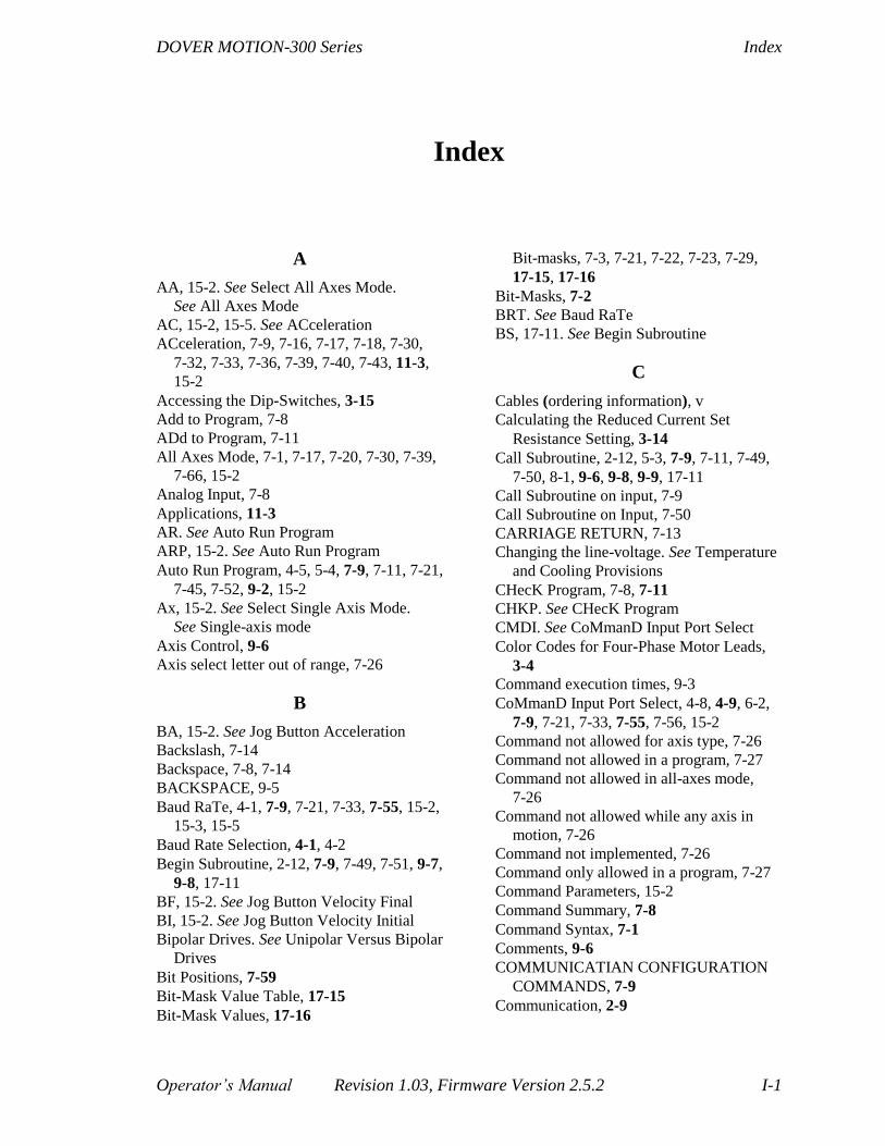
DOVER MOTION-300 Series Index
Operator’s Manual Revision 1.03, Firmware Version 2.5.2 I-1
Index
A
AA, 15-2. See Select All Axes Mode.
See All Axes Mode
AC, 15-2, 15-5. See ACceleration
ACceleration, 7-9, 7-16, 7-17, 7-18, 7-30,
7-32, 7-33, 7-36, 7-39, 7-40, 7-43, 11-3,
15-2
Accessing the Dip-Switches, 3-15
Add to Program, 7-8
ADd to Program, 7-11
All Axes Mode, 7-1, 7-17, 7-20, 7-30, 7-39,
7-66, 15-2
Analog Input, 7-8
Applications, 11-3
AR. See Auto Run Program
ARP, 15-2. See Auto Run Program
Auto Run Program, 4-5, 5-4, 7-9, 7-11, 7-21,
7-45, 7-52, 9-2, 15-2
Ax, 15-2. See Select Single Axis Mode.
See Single-axis mode
Axis Control, 9-6
Axis select letter out of range, 7-26
B
BA, 15-2. See Jog Button Acceleration
Backslash, 7-14
Backspace, 7-8, 7-14
BACKSPACE, 9-5
Baud RaTe, 4-1, 7-9, 7-21, 7-33, 7-55, 15-2,
15-3, 15-5
Baud Rate Selection, 4-1, 4-2
Begin Subroutine, 2-12, 7-9, 7-49, 7-51, 9-7,
9-8, 17-11
BF, 15-2. See Jog Button Velocity Final
BI, 15-2. See Jog Button Velocity Initial
Bipolar Drives. See Unipolar Versus Bipolar
Drives
Bit Positions, 7-59
Bit-Mask Value Table, 17-15
Bit-Mask Values, 17-16
Bit-masks, 7-3, 7-21, 7-22, 7-23, 7-29,
17-15, 17-16
Bit-Masks, 7-2
BRT. See Baud RaTe
BS, 17-11. See Begin Subroutine
C
Cables (ordering information), v
Calculating the Reduced Current Set
Resistance Setting, 3-14
Call Subroutine, 2-12, 5-3, 7-9, 7-11, 7-49,
7-50, 8-1, 9-6, 9-8, 9-9, 17-11
Call Subroutine on input, 7-9
Call Subroutine on Input, 7-50
CARRIAGE RETURN, 7-13
Changing the line-voltage. See Temperature
and Cooling Provisions
CHecK Program, 7-8, 7-11
CHKP. See CHecK Program
CMDI. See CoMmanD Input Port Select
Color Codes for Four-Phase Motor Leads,
3-4
Command execution times, 9-3
CoMmanD Input Port Select, 4-8, 4-9, 6-2,
7-9, 7-21, 7-33, 7-55, 7-56, 15-2
Command not allowed for axis type, 7-26
Command not allowed in a program, 7-27
Command not allowed in all-axes mode,
7-26
Command not allowed while any axis in
motion, 7-26
Command not implemented, 7-26
Command only allowed in a program, 7-27
Command Parameters, 15-2
Command Summary, 7-8
Command Syntax, 7-1
Comments, 9-6
COMMUNICATIAN CONFIGURATION
COMMANDS, 7-9
Communication, 2-9

Index DOVER MOTION-300 Series
I-2 Revision 1.03, Firmware Version 2.5.2 Operator’s Manual
Communication Configuration Commands,
7-55
Communications Port, 4-8, 4-9
Communications Port Selection, 4-9, 7-56
Computer (See also PC), 1-1, 2-2, 2-3, 2-9,
2-13, 4-1, 4-7, 5-1, 5-2, 5-3, 5-4, 5-5, 5-8,
5-11, 6-1, 7-16, 7-48, 7-54, 8-1, 9-3, 9-4,
9-8, 16-1, 17-3
Connector Pin-outs, 16-1
Converting to 230 Volt 50/60 Hz Operation.
See Temperature and Cooling Provisions
Cooling Provisions. See Temperature and
Cooling Provisions
Creating Programs, 9-1
CS. See Call Subroutine
CS SUB, 17-11
CSI. See Call Subroutine on Input
Ctrl+D, 9-5
CTRL+D, 5-3, 7-13
CTRL+H, 7-14
Ctrl+I, 9-5
CTRL+I, 7-13
CTRL+M, 7-13
Ctrl+P, 9-5
CTRL+P, 7-13
CTRL+Q, 7-15, 9-2
CTRL+S, 7-15
Current. See Current and Resistance
Current and Resistance, 3-10
Current Dip-Switch Setting, 3-12
Current Resistance Settings. See Main
Current Resistance Settings for MDM7
And SDM7 Drive Modules
Current Setting, 3-10
Customer Service, v, 17-22
D
DC. See Display Character
DD. See Display Directory
Debugging Programs, 5-12
DEFAULT COMMANDS, 7-9, 7-52
Default States, 15-1
Delete, 7-8
DELETE CHARACTER, 7-14
DELETE LINE, 7-13, 7-14
Deleting Programs, 9-4
Digital I/O Connector, 11-1
Digital I/O connector, 11-1, 11-2, 11-3, 16-6
Digital I/O Connector, 11-1, 16-3
Digital I/O Connector Pin-out, 16-3
Digital switch inputs, 13-4
Dip-switch setting, 3-12
Dip-Switch Settings for Main Current
Resistance, 3-13
Dip-Switch Settings for Reduced Current
Set Resistance, 3-15
Dip-Switches, accessing, 3-15
Display Character, 7-10, 7-48, 7-72
Display Directory, 2-13, 7-1, 7-8, 7-11,
7-52, 9-2
Display String, 7-10, 7-21, 7-69, 7-72, 7-73,
9-8
Display String, No LF, 7-73
Displaying a List of Programs, 9-2
DOWN.BAS, 17-3, 17-9
DOWN.EXE, 17-3, 17-6
DS. See Display String
DSN. See Display String, No LF
DTR/DSR handshaking, 4-3, 4-4
DTR/DSR Handshaking, 4-4
Duplicate label in program, 7-27
E
Edit Program, 2-12, 7-8, 7-12, 9-1, 9-5
Editing Programs, 9-2, 9-5
EM, 17-11. See End of Main Program
Emergency Stop detected, 7-26
Encoder, 2-2, 2-3, 2-4, 2-6, 2-7, 2-8, 7-8, 7-
22, 7-30, 7-33, 7-34, 10-1, 10-2, 10-3, 12-
1, 12-2, 16-6
Encoder Interface, 12-1
End of Main Program, 2-12, 7-9, 7-51, 9-6,
9-8, 17-11
End Subroutine, 2-12, 5-4, 7-9, 7-11, 7-51,
9-8, 9-9, 17-11
ENTER, 9-5
ENTER key, 2-11, 2-14, 5-3, 5-5, 7-1, 7-12,
7-13, 7-72, 9-1
EP. See Edit Program
EP 4, 9-5
EP TEST, 9-5
Error allocating GPIB I/O buffers, 7-28
Error initializing GPIB port, 4-9, 7-28
Error–Codes and Messages, 7-26
Errors and Debugging, 9-9
ES. See End Subroutine
Escape, 7-14
ESCAPE, 9-5

DOVER MOTION-300 Series Index
Operator’s Manual Revision 1.03, Firmware Version 2.5.2 I-3
ESCAPE key, 2-12, 4-5, 5-4, 7-16, 7-18,
7-46, 9-2, 9-3, 10-3
ESCAPE Key, 7-9
ESTOP, 7-17, 7-22
ESTOP Input Latch Reset, 7-17
EX31.BAS, 5-6, 5-9, 5-10, 17-3
EX31.BAS—Illustrates Move Finished, 5-6
EX32.BAS, 5-8, 5-11, 17-3
EX32.BAS—Illustrates Serial Interrupt
Method, 5-8
EX33.BAS, 5-9, 5-10, 5-11, 17-3
EX33.BAS—Illustrates Polling Mode, 5-10
EX35.BAS, 12-2, 17-3, 17-4
EX35.BAS—Illustrates Quasi-Closed Loop
Operation, 17-4
Example Programs, 5-5
eXecute Program, 2-13, 4-5, 7-9, 7-11, 7-45,
7-52, 9-7, 9-9
eXecute Program Single step, 7-9, 7-46, 9-9
eXecute Single step, 7-9
EXECUTION COMMANDS, 7-9, 7-45
Exit Edit, 7-8
EXIT EDIT, 7-14
F
Fan inlet filter, 2-2
Four (“Two”)–Phase Stepping Motors, 3-3
Four-Phase Motor Coils and Leads, 3-3
Fractional parameter value not allowed,
7-26
Front Panel, 4-1
Full Coil. See Full Coil Versus Half Coil
Fuses, changing. See Temperature and
Cooling Provisions
G
GADR, 15-2. See GPIB ADdRess
Getting Started, 2-2
GLTF, 15-2. See GPIB Line Terminator
Flag
GPIB ADdRess, 4-8, 6-2, 7-9, 7-33, 7-56,
15-2
GPIB Connector (IEEE-488), 16-7
GPIB Connector (IEEE-488) Pin-out, 16-7
GPIB controller, 6-1, 7-56, 7-57, 7-58
GPIB Line Terminator Flag, 6-2, 7-9, 7-21,
7-33, 7-56, 7-59, 15-2
GPIB mode, 7-21
GPIB parallel port, 1-1, 2-9, 4-7, 4-8, 6-1,
8-1, 16-1
GPIB serial poll status byte, 7-57, 7-58
GPIB service request mask byte, 7-57, 7-58
GPIB SRQ Bits Mask, 6-2, 7-9, 7-21, 7-33,
7-57, 7-58, 7-59, 15-2
GPIB TeRMinal Mode, 6-2, 7-9, 7-60, 7-61,
15-2
GSRB, 15-2. See GPIB SRQ Bits Mask
GTRM, 15-2. See GPIB TeRMinal Mode
H
HA, 15-2, 15-5. See Homing Acceleration
Half Coil. See Full Coil Versus Half Coil
Handshaking, 2-9, 2-11, 4-3
Hardware and Software Handshaking, 4-3,
4-4
Hardware Considerations, 10-1
Hardware error initializing axis board, 7-28
Hardware error initializing axis functions, 7-
26
Hardware error initializing I/O board, 7-28
Hardware error initializing serial port, 7-26
Hardware error initializing timer channel, 7-
26
Hardware HandShaKe Mode, 4-4, 7-9, 7-21,
7-33, 7-60, 15-2
HDST. See Homing Search DiSTance.
See Homing Search DiSTance. See
Homing Search DiSTance. See Homing
Search DiSTance
Help Diskette, 1-1, 9-4, 12-2, 17-3
HF, 15-2, 15-5. See Homing Velocity Final
HHSK, 15-2. See Hardware HandShaKe
Mode
HI, 15-2, 15-5. See Homing Velocity Initial
HM. See Homing Mode. See Homing Mode.
See Homing Mode. See Homing Mode
Home moves, 12-2
Homing Acceleration, 7-9, 7-30, 7-32, 7-33,
7-35, 7-38, 7-39, 10-3, 15-2
HOMING COMMANDS, 7-9, 7-35
Homing Mode, 7-9, 7-38, 15-2
Homing Search Distance, 7-38
Homing Search DiSTance, 7-9. See Homing
Search DiSTance. See Homing Search
DiSTance

Index DOVER MOTION-300 Series
I-4 Revision 1.03, Firmware Version 2.5.2 Operator’s Manual
Homing Velocity Final, 7-9, 7-30, 7-32,
7-33, 7-36, 7-37, 7-38, 7-39, 7-41, 7-42,
10-2, 10-3, 15-2
Homing Velocity Initial, 7-9, 7-30, 7-32,
7-33, 7-37, 7-38, 7-39, 7-41, 7-42, 10-2,
10-3, 15-2
I
I/O, 2-3, 11-2
I/O commands, 9-3
IC, 7-64, 15-2. See Idle Current, All Axes
ICA, 7-64, 15-3. See Idle Current, per Axis
IDL, 15-3. See Idle Current DeLay, all Axes
IDLA. See Idle Current DeLay, per Axis
Idle Current, 7-16, 7-63, 7-64, 15-3
Idle Current DeLay, 7-65, 15-3
Idle Current DeLay, all axes, 7-9
Idle Current DeLay, all Axes, 7-63
Idle Current DeLay, All Axes, 7-9, 7-32,
7-33, 7-63, 7-64
Idle Current DeLay, per axis, 7-9
Idle Current DeLay, per Axis, 7-9, 7-32,
7-33, 7-64, 15-3
Idle Current DeLay, Per Axis, 7-63
Idle Current, all axes, 7-9, 15-2
Idle Current, All Axes, 7-9, 7-32, 7-33, 7-63
Idle Current, per Axis, 7-63, 15-3
Idle Current, Per Axis, 7-9, 7-32, 7-33,
7-63, 15-3
Illegal characters in label, 7-27
Illegal characters in program name, 7-27
Illegal label--must start with a letter, 7-27
Illegal numeric parameter, 7-26
Immediate Mode, 5-3
Initial homing vel (HI) greater then final
(HF), 7-26
Initial velocity (VI) greater then final (VF),
7-26
Initialization Error, 4-9
Input Code Parameters, 7-4
Insert comments into a program, 9-6
Insert Line, 7-8
Interfacing to DOVER MOTION
Positioning Stages, 2-4
Internal memory allocation error, 7-28
Interrupt, 5-4
Interrupt mode, 5-4, 5-8
IOBN. See Select Current I/O-Board
Number. See Select Current I/O-Board
Number
J
JA. See Joystick Acceleration
JC. See Joystick Center Value
JD. See Joystick Deadband
JE. See Joystick Enable
JG, 15-3. See Joystick Gain
JIC, 15-3. See Joystick Input Channel
JMAX, 15-3. See Joystick MAXimum Input
Limit
JMIN, 15-3. See Joystick MINimum Input
Limit
JNL, 15-3. See Joystick Negative Position
Limit
Jog, 4-5, 4-6
JOG, 1-1, 2-5, 2-8
JOG button, 2-5
Jog Button Acceleration, 4-7, 7-9, 7-32,
7-33, 7-39, 7-40, 7-41, 7-42, 15-2
Jog Button Velocity Final, 4-7, 7-9, 7-32,
7-33, 7-39, 7-41, 7-42, 15-2
Jog Button Velocity Initial, 4-6, 7-9, 7-32,
7-33, 7-39, 7-41, 7-42, 15-2
Joystick Acceleration, 7-10, 7-32, 7-33,
7-65, 7-67, 7-68, 13-4, 15-3
Joystick Auto-Zero, 7-10, 7-24, 7-32, 7-33,
7-65, 7-70, 15-4
Joystick Center Value, 7-10, 7-24, 7-32,
7-33, 7-65, 7-67, 7-70, 13-3, 15-3, 15-4
Joystick Commands, 7-65
Joystick connections, 13-2
Joystick connector, 13-2
Joystick Connector, 16-6
Joystick Connector Pin-out, 16-6
Joystick Deadband, 7-10, 7-66, 7-67, 13-3,
15-3
Joystick Enable, 7-10, 7-18, 7-66, 13-3,
15-3
Joystick Gain, 7-10, 7-32, 7-33, 7-66, 7-67,
13-3, 15-3
Joystick Input Channel, 7-10, 7-24, 7-32,
7-33, 7-67, 13-3, 15-3
Joystick Interface, 13-2
Joystick MAXimum Input Limit, 7-10, 7-32,
7-33, 7-67, 7-68, 13-4, 15-3

DOVER MOTION-300 Series Index
Operator’s Manual Revision 1.03, Firmware Version 2.5.2 I-5
Joystick MINimum Input Limit, 7-10, 7-32,
7-33, 7-67, 7-68, 13-4, 15-3
Joystick Negative Position Limit, 7-10, 7-
24, 7-32, 7-33, 7-68, 7-69, 15-3
Joystick Positive Position Limit, 7-10, 7-32,
7-69, 15-4
Joystick Qualifier Input, 7-10, 7-32, 7-67, 7-
69, 7-70, 13-4, 15-4
Joystick Zero, 7-24, 15-4
Joysticks, 2-2, 2-3, 7-8, 7-10, 7-18, 7-20, 7-
21, 7-22, 7-24, 7-65, 7-66, 7-67, 7-68, 7-
69, 7-70, 13-2, 13-3, 13-4, 17-15
JP. See JumP to Label or Line #
JP to BS command not allowed, 7-27
JPI. See JumP on Input
JPL, 15-4. See Joystick Positive Position
Limit
JQI, 15-4. See Joystick Qualifier Input
JumP on Input, 7-9, 7-52
Jump to Label or Line #, 4-5, 7-13
JumP to Label or Line #, 5-3, 7-9, 7-11,
7-14, 7-24, 7-25, 7-33, 7-45, 7-46, 7-50,
7-51, 7-52, 8-1, 9-2, 9-3, 9-6, 9-7, 9-9
JZ, 15-4. See Joystick Auto-Zero
K
Kill Program, 7-8, 7-14, 9-4
KP. See Kill Program
L
Limit And Home Switches, 10-1
LIMit Polarity, 7-9, 7-32, 7-53, 15-4
Limit PullUP/down, 7-10, 7-74, 15-4
Limit Stop, 7-16, 7-54, 10-3
Limit Stop Disabled, 10-3
Limit Stop Enabled, 10-3
Limit Stop, All Axes, 7-9, 7-32, 7-33, 7-53,
7-54, 15-4
Limit Stop, Per Axis, 7-9, 7-32, 7-33, 7-53,
7-54, 15-4
Limit Stops Enabled, 7-53
Limit/Encoder, 2-6, 2-7, 2-8, 10-1, 16-6
Limit/Encoder connector, 2-6, 12-1
Limit/Encoder Connector, 10-1, 16-5
Limit/Encoder Connector Pin-out, 2-6, 10-1,
16-5
LIMP, 15-4. See LIMit Polarity
Line-voltage. See Temperature and Cooling
Provisions
List Program, 7-8, 7-14, 7-15, 9-2, 9-3, 9-4
LP. See List Program. See List Program
LPUP. See Limit PullUP/down. See Limit
PullUP/down. See Limit PullUP/down.
See Limit PullUP/down
LS, 15-4. See Limit Stop, All Axes
LSA, 15-4. See Limit Stop, Per Axis
M
MA. See Move Absolute
Main Current, 3-10, 3-12, 7-63. See Main
Current and Reduced Idle Current
Main Current Resistance, 3-10
Main Current Resistance Settings for
MDM7 And SDM7 Drive Modules, 3-11
Master Reset, 4-7
MC. See Move Continuous
MCUR, 15-4. See Motor Output CURrent
MCVI. See Move Continuous at VI Velocity
MEMORY COMMANDS, 7-8, 7-11
Memory error initializing axis-I/O
functions, 7-28
MF, 15-4. See Move Finished
MH, 17-11, 17-12, 17-13, 17-14. See Move
Home
Microsoft QuickBasic, 5-5, 5-8, 17-3
Midrange Resonance Suppression, 3-10
MISCELLANEOUS COMMANDS, 7-10,
7-71
Motion Calculations, 17-19
Motor, 3-2
Motor Connection, 3-11
Motor connector, 16-4
Motor Connector, 2-7, 3-11, 3-10
Motor Connector Pin-out, 2-7, 3-10, 16-4
Motor current, 7-16
MOTOR CURRENT COMMANDS, 7-9, 7-
63
Motor current dip-switches, 2-8
Motor Leads, color codes, 3-4
Motor Output CURrent, 7-9, 7-64, 15-3,
15-4, 15-5
Motor Ratings, 3-2
Motor Wiring And Drive, 3-2
Motors, 3-10
Move Absolute, 7-1, 7-2, 7-8, 7-16
MOVE COMMANDS, 7-8, 7-16

Index DOVER MOTION-300 Series
I-6 Revision 1.03, Firmware Version 2.5.2 Operator’s Manual
Move Continuous, 7-8, 7-17
Move Continuous at VI Velocity, 7-8, 7-17
Move distance too large, 7-26
Move Finished, 5-4, 5-6, 5-9, 5-10, 7-8, 7-9,
7-16, 7-21, 7-33, 7-54, 15-4
Move Home, 7-9, 7-35, 7-36, 7-38, 7-39, 9-
8, 10-2, 10-3, 17-11, 17-12, 17-13, 17-14
Move Relative, 2-11, 2-12, 7-8, 7-16, 7-18,
7-54, 9-2, 9-8, 17-11
Move to Encoder Position, 7-8, 7-17
Move to Encoder Position at VI Velocity,
7-8, 7-17
MP. See Move to Encoder Position
MPVI. See Move to Encoder Position at VI
Velocity
MR, 17-11. See Move Relative
N
DOVER MOTION-300 Command Set, 7-1
DOVER MOTION-300 SERIES, 2-3
DOVER MOTION-PCX SERIES, 2-3
Next Line, 7-8
NEXT LINE, 7-13
No Call Sub executed for End Sub
command, 7-27
No error, 7-26
No Error, 7-25
No matching entry for Auto Run Program #,
7-28
No matching line or label for command,
7-27
No matching program names found, 7-27
No matching program numbers found, 7-27
No parameters allowed for command, 7-26
Non-volatile memory, 9-1
NP. See reName or Renumber Program
NVRAM error, recovered from backup
copy, 7-27
O
ON/OFF switch, 4-1
Operating Other Stages, 2-6
P
Parameter syntax error, 7-26
Parameter value out of range, 7-26
Parameter(s) not allowed in query
command, 7-26
Parameter(s) required in all-axes Mode,
7-26
PAUC. See PAUse program on Character
PAUI. See PAUse program on Input
PAUL. See PAUse program on input Level
PAUM. See PAUse Message enable
PAUS. See PAUse program on Start button
PAUse Message enable, 7-9, 7-47
PAUse pragram on Character, 7-9
PAUse pragram on Input, 7-9
PAUse pragram on input Level, 7-9
PAUse pragram on Start butten, 7-9
PAUse program on Character, 7-46
PAUse program on Input, 7-47
PAUse program on input Level, 7-47
PAUse program on Start button, 7-48
PC (See also "Computer"), 2-3, 2-9, 2-13, 2-
14, 5-3, 6-1, 7-1, 9-4, 17-3, 17-7, 17-9
Phase Stepping Motors, 3-3
Pins and Channels, 12-1
Polling, 5-4, 5-8, 5-10
Power Issues: Changing Fuses, and
Converting to 230 Volt 50/60 Hz
Operation, 17-1
Preventing Cable Noise, 12-1
Previous Line, 7-8
PREVIOUS LINE, 7-13
Program aborted, axis in limit detected,
7-27
Program Editing Functions, 9-5
PROGRAM FLOW COMMANDS, 7-9,
7-49
Program Illustrating Subroutines, 9-8
Program is currently executing, 7-27
Program Mode, 9-1
Program name already in use, 7-27
Program name required, 7-27
Program name too long, 7-27
Program number already in use, 7-27
Program Select, 4-5
Program Structure, 9-6
Programmed Wait For Start, 4-7
Q
Quasi-closed loop, 12-2, 17-3
Queries, 7-2
Query invalid for command, 7-26

DOVER MOTION-300 Series Index
Operator’s Manual Revision 1.03, Firmware Version 2.5.2 I-7
R
RA. See Report Axis Status Code
RAI. See Report Analog Input
Ratings for Dover Motion Stepping Motors,
3-2
RCV. See Report Current Velocity
RD. See Report Defaults
RDDS. See Report Delta Bits for DS Inputs
RDF. See Report DiFferential Analog Input
RDI. See Report Delta Bits for Inputs
RDS. See Report DS Joystick Inputs
RE. See Report Encoder
READ.ME, 17-3
Reading and Setting Joystick Values, 13-2
Reading and Setting the Encoder Position,
12-2
Rear panel, 2-6, 4-7, 5-1, 10-1, 11-1, 12-1,
13-2, 16-1
Reduced Current Set Resistance, 3-10, 3-14
Reduced Current Set Resistance Setting. See
3.3.4. Calculating the Reduced Current
Set Resistance Setting
Reduced Idle Current, 3-10, 7-63. See Main
Current and Reduced Idle Current
Reduced Idle Current Torque, 3-14
Relay Switch, 14-1
reName or Renumber Program, 7-8, 7-14, 7-
15, 9-4
Repetitive Iterations within Programs, 9-6
Report Analog Input, 7-8, 7-20, 7-24
Report AuXiliary Encoder, 7-8, 7-30, 7-34
Report Axis, 7-8
Report Axis Status Code, 7-20
REPORT COMMANDS, 7-8, 7-20
Report Current Velocity, 7-8, 7-21, 13-3
Report Defaults, 7-8, 7-21, 7-57, 7-58
Report Delta Bits Inputs, 7-8
Report Delta-Bits for DS Inputs, 7-21
Report Delta-Bits for Inputs, 7-22
Report DiFferential Analog Input, 7-8, 7-21
Report DS Joystick Inputs, 7-21, 7-22, 13-4
Report Encoder, 7-8, 7-22, 12-1, 12-2
Report EStop Input Latch, 7-8, 7-22
Report Inputs, 5-5, 7-3, 7-8, 7-22, 7-23,
11-2
Report Inputs as Binary, 7-8, 7-23
Report Inputs as Hex, 7-8, 7-23
Report Inputs as HL String, 7-8, 7-23
Report Joystick, 7-8, 7-24, 7-69, 13-3, 13-4
Report Joystick Position Limits, 7-24, 7-69
Report Last ERror code, 7-8, 7-28
Report Last Error Message, 7-8, 7-25
Report Limits status, 7-8
Report Limits Status, 7-25, 7-53, 10-3
Report Moving Flags, 7-8, 7-28
Report Moving Status character, 7-30
Report Moving Status Character, 7-8, 7-30
Report Outputs, 7-8, 7-29
Report Outputs as Binary, 7-8, 7-29
Report Outputs as Hex, 7-8, 7-29
Report Outputs as HL String, 7-8, 7-29
Report Position, 2-11, 7-1, 7-8, 7-29, 7-35
Report Revision, 7-8, 7-30
Report Status, 5-4, 5-10, 5-11, 7-8, 7-16,
7-54
Report Velocity/Acceleration Values, 7-8,
7-30, 7-36, 7-37, 7-38, 7-40, 7-43
Report Z/Home Active State, 7-8, 7-31
Report Z/Home Input, 7-8, 7-23
Required parameter(s) missing for
command, 7-26
RES. See Report EStop Input Latch
RESET, 7-52. See RESET Controller
RESET Controller, 4-1, 4-4, 7-9, 7-33, 7-52,
7-54, 7-55, 7-56, 7-60, 7-61, 15-1
Resistance. See Current and Resistance
ret (See RETURN key), 2-11
RETURN key, 2-11
Returning equipment to DOVER MOTION,
17-22
RH. See Report Z/Home Input
RI. See Report Inputs
RIB. See Report Inputs as Binary
RIH. See Report Inputs as Hex
RIS. See Report Inputs as HL String
RJ. See Report Joystick
RJL. See Report Joystick Position Limits
RL. See Report Limits Status
RLEM, 7-26. See Report Last Error
Message
RLER, 7-26. See Report Last ERror Code
RMF. See Report Moving Flags
RO. See Report Outputs
ROB. See Report Outputs as Binary
ROH. See Report Outputs as Hex
ROS. See Report Outputs as HL String
RP. See Report Position
RR. See Report Revision

Index DOVER MOTION-300 Series
I-8 Revision 1.03, Firmware Version 2.5.2 Operator’s Manual
RS. See Report Moving Status Character
RS-232 serial port, 1-1, 2-9, 2-13, 4-1, 4-7,
4-8, 5-1, 5-2, 5-6, 5-8, 6-1, 7-26, 7-48, 7-
54, 7-72, 8-1, 10-3
RS-232 Serial Port Connector, 2-10, 5-2,
16-2
Running Programs, 9-3
RV. See Report Velocity/Acceleration
Values
RXE. See Report AuXiliary Encoder
RZ. See Report Z/Home Active State
S
Save AXis Defaults, 7-8, 7-32, 7-35, 7-36,
7-37, 7-38, 7-39, 7-40, 7-41, 7-42, 7-43,
7-53, 7-63, 7-64, 7-65, 7-66, 7-67, 7-68,
7-69, 7-70, 7-74, 15-1
Save Defaults, 4-7, 5-4, 7-8, 7-21, 7-32,
7-33, 7-34, 7-35, 7-36, 7-37, 7-38, 7-39,
7-40, 7-41, 7-42, 7-43, 7-44, 7-52, 7-53,
7-54, 7-55, 7-56, 7-57, 7-58, 7-60, 7-61,
7-63, 7-64, 7-65, 7-66, 7-67, 7-68, 7-69,
7-70, 7-71, 7-74, 15-1, 15-2
SD. See Save Defaults
SE, 15-4. See Set Encoder. See Save AXis
Defaults
Select All Axes Mode, 7-1, 7-10, 7-17,
7-18, 7-20, 7-30, 7-39, 7-66, 7-71, 9-6,
10-2, 15-2
Select Current I/O-Board Number, 7-10,
7-73, 15-3
Select GPIB TeRMinal Mode, 7-21
Select Single Axis mode, 7-1
Select Single Axis Mode, 7-8, 7-10, 7-16,
7-17, 7-18, 7-20, 7-26, 7-30, 7-39, 7-63,
7-66, 7-71, 9-6, 10-2, 15-2
Select Velocity SET, 7-9, 7-21, 7-33, 7-44,
15-4
Serial poll status byte. See GPIB serial poll
status byte
Serial port. See RS-232 serial port
Serial Port Configuration, 5-1
Serial Port Connector, 2-10, 5-2, 16-2
Serial Port Connector Pin-out, 2-10, 16-2
Service request mask byte. See GPIB service
request mask byte
Set Auxiliary Encoder, 7-35
Set AuXiliary Encoder, 7-8
Set auXiliary Encoder Input CHannel, 7-34
Set AuXiliary Encoder Input Channel, 15-4
Set AuXiliary Encoder Input CHannel,
7-21, 7-33, 7-34
Set AuXiliary Input CHannel, 7-8
SET COMMANDS, 7-8, 7-32
Set Encoder, 7-8, 7-33, 12-2, 15-4
Set GPIB TeRMinal Mode, 7-60
Set Outputs, 7-8, 7-29, 7-33, 11-2, 11-3,
15-4
Set Position, 7-8, 7-34, 7-35, 8-1, 15-4
Set Position/Report Position, 7-18
Set Relay, 7-8, 7-34, 15-4
Set TERMinal Mode, 7-60, 7-62
Setting Outputs and Reading Inputs, 11-2
Show HELP Screen, 7-10, 7-73, 17-3
SHSK, 15-4. See Software HandShaKe
Mode
Single-axis mode, 7-17, 7-39
SO, 15-4. See Set Outputs
Software HandShaKe Mode, 4-4, 7-9, 7-21,
7-61, 9-3, 15-4
Software Implementation, 10-2
SP, 15-4. See Set Position
Speed. See Speed and Torque
SR. See Set Relay. See Set Relay
ST. See STop Move
START, 1-1, 2-5, 2-8, 2-13, 4-1, 4-4, 4-5, 4-
6, 4-7, 6-1, 7-45, 7-49, 7-52, 9-3
START button, 2-5, 2-8
Stepping Motor Ratings, 3-2
STOP, 1-1, 2-5, 4-1, 4-4, 4-5, 4-6, 4-7, 4-8,
7-18, 7-46, 9-3
STOP button, 2-5, 2-8
STOP Button, 7-9
STop Move, 7-8, 7-16, 7-18, 7-19, 10-3
Switches, 13-4
SXCH, 15-4. See Set auXiliary Encoder
Input CHannel
SXE. See Set Auxiliary Encoder
System Configuration, 2-2
T
TAB, 7-13
Temperature Provisions. See Temperature
and Cooling Provisions
TERM. See TERMinal Mode
Terminal, 5-1, 5-3, 16-1
Terminal Emulation Software, 2-9
Terminal Emulator, 2-14
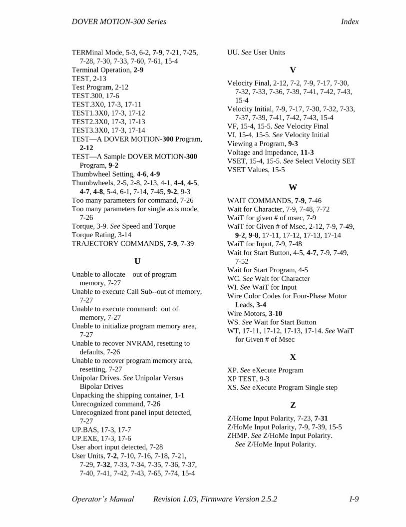
DOVER MOTION-300 Series Index
Operator’s Manual Revision 1.03, Firmware Version 2.5.2 I-9
TERMinal Mode, 5-3, 6-2, 7-9, 7-21, 7-25,
7-28, 7-30, 7-33, 7-60, 7-61, 15-4
Terminal Operation, 2-9
TEST, 2-13
Test Program, 2-12
TEST.300, 17-6
TEST.3X0, 17-3, 17-11
TEST1.3X0, 17-3, 17-12
TEST2.3X0, 17-3, 17-13
TEST3.3X0, 17-3, 17-14
TEST—A DOVER MOTION-300 Program,
2-12
TEST—A Sample DOVER MOTION-300
Program, 9-2
Thumbwheel Setting, 4-6, 4-9
Thumbwheels, 2-5, 2-8, 2-13, 4-1, 4-4, 4-5,
4-7, 4-8, 5-4, 6-1, 7-14, 7-45, 9-2, 9-3
Too many parameters for command, 7-26
Too many parameters for single axis mode,
7-26
Torque, 3-9. See Speed and Torque
Torque Rating, 3-14
TRAJECTORY COMMANDS, 7-9, 7-39
U
Unable to allocate—out of program
memory, 7-27
Unable to execute Call Sub--out of memory,
7-27
Unable to execute command: out of
memory, 7-27
Unable to initialize program memory area,
7-27
Unable to recover NVRAM, resetting to
defaults, 7-26
Unable to recover program memory area,
resetting, 7-27
Unipolar Drives. See Unipolar Versus
Bipolar Drives
Unpacking the shipping container, 1-1
Unrecognized command, 7-26
Unrecognized front panel input detected,
7-27
UP.BAS, 17-3, 17-7
UP.EXE, 17-3, 17-6
User abort input detected, 7-28
User Units, 7-2, 7-10, 7-16, 7-18, 7-21,
7-29, 7-32, 7-33, 7-34, 7-35, 7-36, 7-37,
7-40, 7-41, 7-42, 7-43, 7-65, 7-74, 15-4
UU. See User Units
V
Velocity Final, 2-12, 7-2, 7-9, 7-17, 7-30,
7-32, 7-33, 7-36, 7-39, 7-41, 7-42, 7-43,
15-4
Velocity Initial, 7-9, 7-17, 7-30, 7-32, 7-33,
7-37, 7-39, 7-41, 7-42, 7-43, 15-4
VF, 15-4, 15-5. See Velocity Final
VI, 15-4, 15-5. See Velocity Initial
Viewing a Program, 9-3
Voltage and Impedance, 11-3
VSET, 15-4, 15-5. See Select Velocity SET
VSET Values, 15-5
W
WAIT COMMANDS, 7-9, 7-46
Wait for Character, 7-9, 7-48, 7-72
WaiT for given # of msec, 7-9
WaiT for Given # of Msec, 2-12, 7-9, 7-49,
9-2, 9-8, 17-11, 17-12, 17-13, 17-14
WaiT for Input, 7-9, 7-48
Wait for Start Button, 4-5, 4-7, 7-9, 7-49,
7-52
Wait for Start Program, 4-5
WC. See Wait for Character
WI. See WaiT for Input
Wire Color Codes for Four-Phase Motor
Leads, 3-4
Wire Motors, 3-10
WS. See Wait for Start Button
WT, 17-11, 17-12, 17-13, 17-14. See WaiT
for Given # of Msec
X
XP. See eXecute Program
XP TEST, 9-3
XS. See eXecute Program Single step
Z
Z/Home Input Polarity, 7-23, 7-31
Z/HoMe Input Polarity, 7-9, 7-39, 15-5
ZHMP. See Z/HoMe Input Polarity.
See Z/HoMe Input Polarity.

Index DOVER MOTION-300 Series
I-10 Revision 1.03, Firmware Version 2.5.2 Operator’s Manual