
Programmable Printing Depository with Envelope Dispenser ... deposit.pdf · programmable printing...
52
13.4-i PROGRAMMABLE PRINTING DEPOSITORY WITH ENVELOPE DISPENSER OPTION Contents Programmable Printing Depository with Envelope Dispenser Option Chapter 13.4 INTRODUCTION ...................................................................................................... 13.4-1 GENERAL DESCRIPTION ....................................................................................... 13.4-1 DEPOSITORY BINS............................................................................................. 13.4-2 DISPENSER .......................................................................................................... 13.4-2 ENVELOPE SPECIFICATION ............................................................................ 13.4-3 Size .................................................................................................................... 13.4-3 Paper .................................................................................................................. 13.4-3 Construction ...................................................................................................... 13.4-3 Colour ................................................................................................................ 13.4-3 FUNCTIONAL DESCRIPTION ................................................................................ 13.4-4 HARDWARE......................................................................................................... 13.4-4 Security Shutter ................................................................................................. 13.4-4 Transport System............................................................................................... 13.4-4 Envelope Dispenser ........................................................................................... 13.4-4 Print Module...................................................................................................... 13.4-5 Depository Bin .................................................................................................. 13.4-5 Control Module ................................................................................................. 13.4-6 Sensors .............................................................................................................. 13.4-7 OPERATION ......................................................................................................... 13.4-9 Normal Operation Commands .......................................................................... 13.4-9 CIRCUIT DESCRIPTION................................................................................... 13.4-12 Block Diagram ................................................................................................ 13.4-12 SDC Interface .................................................................................................. 13.4-12 Ink Jet Drive .................................................................................................... 13.4-13 Temperature Monitor ...................................................................................... 13.4-14 Sensors ............................................................................................................ 13.4-14 Motor Control .................................................................................................. 13.4-15 SERVICE AIDS ....................................................................................................... 13.4-16 TEST TOOLS ........................................................................................................... 13.4-16
-
Upload
trannguyet -
Category
Documents
-
view
219 -
download
2
Transcript of Programmable Printing Depository with Envelope Dispenser ... deposit.pdf · programmable printing...

PROGRAMMABLE PRINTING DEPOSITORY WITH ENVELOPE DISPENSER OPTION
.4-1
.4-13.4-23.4-2.4-33.4-3
13.4-33.4-33.4-3
.4-43.4-43.4-43.4-43.4-4
3.4-53.4-53.4-613.4-73.4-93.4-94-12.4-12.4-12.4-13.4-143.4-14.4-15
.4-16
.4-16
Contents
Programmable Printing Depositorywith Envelope Dispenser Option
Chapter 13.4
INTRODUCTION ...................................................................................................... 13
GENERAL DESCRIPTION....................................................................................... 13DEPOSITORY BINS............................................................................................. 1DISPENSER .......................................................................................................... 1ENVELOPE SPECIFICATION ............................................................................ 13
Size .................................................................................................................... 1Paper..................................................................................................................Construction ...................................................................................................... 1Colour................................................................................................................ 1
FUNCTIONAL DESCRIPTION................................................................................ 13HARDWARE......................................................................................................... 1
Security Shutter ................................................................................................. 1Transport System............................................................................................... 1Envelope Dispenser........................................................................................... 1Print Module...................................................................................................... 1Depository Bin .................................................................................................. 1Control Module ................................................................................................. 1Sensors ..............................................................................................................
OPERATION......................................................................................................... 1Normal Operation Commands .......................................................................... 1
CIRCUIT DESCRIPTION................................................................................... 13.Block Diagram ................................................................................................ 13SDC Interface.................................................................................................. 13Ink Jet Drive .................................................................................................... 13Temperature Monitor ...................................................................................... 13Sensors ............................................................................................................ 1Motor Control.................................................................................................. 13
SERVICE AIDS ....................................................................................................... 13
TEST TOOLS ........................................................................................................... 13
13.4-i

PROGRAMMABLE PRINTING DEPOSITORY WITH ENVELOPE DISPENSER OPTION
.4-16
.4-16.4-16-17.4-18.4-19
4-20-20-20
.4-20
4-20.4-21.4-21.4-22.4-223.4-22.4-22
4-22.4-23.4-234-23-23
4-24.4-24.4-24.4-24.4-253.4-25.4-25.4-25.4-25.4-26.4-26.4-26.4-26.4-26-27
-28.4-28
-28
-29-29.4-30.4-30
STRAPPING............................................................................................................. 13
ADJUSTMENTS ...................................................................................................... 13DRIVE BELTS .................................................................................................... 13PRINT HEAD REPLACEMENT........................................................................ 13.4
Purging ............................................................................................................ 13Ink Pad Repositioning ..................................................................................... 13
LUBRICATION ....................................................................................................... 13.GENERAL INSTRUCTIONS ............................................................................. 13.4LUBRICATION POINTS.................................................................................... 13.4
TROUBLESHOOTING............................................................................................ 13
LEVEL 0 DIAGNOSTICS ....................................................................................... 13.INTERFACES ..................................................................................................... 13
LED Interface.................................................................................................. 13Remote Diagnostic Interface (RDI) ................................................................ 13
START-UP MODE.............................................................................................. 13Test Sequence.................................................................................................. 1Test Router ...................................................................................................... 13Test 1H - Microcontroller Confidence and EPROM Sumcheck..................... 13.Test 2H - SRAM Data ..................................................................................... 13Test 3H - SRAM Address ............................................................................... 13
SELECTED TEST MODE .................................................................................. 13.Test 4H – Test All RAM Data (Clear NVRAM) ............................................ 13.4
LEVEL 1 DIAGNOSTICS ....................................................................................... 13.DEPOSITORY..................................................................................................... 13TEST DESCRIPTIONS....................................................................................... 13
Deposit and Print Data .................................................................................... 13Deposit and Print Serial No............................................................................. 13Shutter/Sensor Status....................................................................................... 1Increment Serial Number ................................................................................ 13Clear Transport................................................................................................ 13Disable Depository.......................................................................................... 13SDC Turnaround ............................................................................................. 13Run-to-Run...................................................................................................... 13Tamper Indication ........................................................................................... 13
M_STATUS......................................................................................................... 13M_DATA ............................................................................................................. 13M_DATA (DEPOSITORY TI)............................................................................ 13.4
LEVEL 3 DIAGNOSTICS - TALLIES.................................................................... 13.4DEPOSITORY..................................................................................................... 13
STATE OF HEALTH REPORTING ....................................................................... 13.4
CABLE AND CONNECTOR DATA ...................................................................... 13.4INTERCONNECTION DIAGRAM.................................................................... 13.4CONNECTOR PINOUTS ................................................................................... 13
J1 – SDC I/F.................................................................................................... 13
13.4-ii

PROGRAMMABLE PRINTING DEPOSITORY WITH ENVELOPE DISPENSER OPTION
.4-30.4-30.4-30.4-313.4-31.4-31.4-32.4-32
-333.4-33.4-33.4-34
3.4-34.4-34.4-35
.4-36
J2 – Power ...................................................................................................... 13J3 – Motors...................................................................................................... 13J4 – Bin-In ....................................................................................................... 13J5 – Envelope Dispenser I/F............................................................................ 13J6 – Sensors..................................................................................................... 1J7 – Facia Interface ......................................................................................... 13J8 – Ink Jet Print Head ................................................................................... 13J9 – Remote Diagnostics ................................................................................ 13
CABLING INFORMATION............................................................................... 13.4Sensor Harness ................................................................................................ 1Bin-In Switch Harness .................................................................................... 13Motor Harness ................................................................................................. 13Power and Shutter Harness ............................................................................. 1SDC Harness ................................................................................................... 13Print Head Harness.......................................................................................... 13
SCHEMATICS ......................................................................................................... 13
13.4-iii

PROGRAMMABLE PRINTING DEPOSITORY WITH ENVELOPE DISPENSER OPTION
13.4-iv

PROGRAMMABLE PRINTING DEPOSITORY WITH ENVELOPE DISPENSER OPTION
Contents
Chapter 13.4
Programmable Printing Depositorywith Envelope Dispenser Option
INTRODUCTIONThis chapter describes the Programmable Printing Depository with EnvelopeDispenser Option (PPD-EDO) module available as a feature on the SHUVRQDV��(5886) ATM.
GENERAL DESCRIPTION
ExternalTransport
PrintHead
MainTransport
Bin
EnvelopeDispenser
EnvelopeCassette
ControllerPCB
13.4-1
PROGRAMMABLE PRINTING DEPOSITORY WITH ENVELOPE DISPENSER OPTION
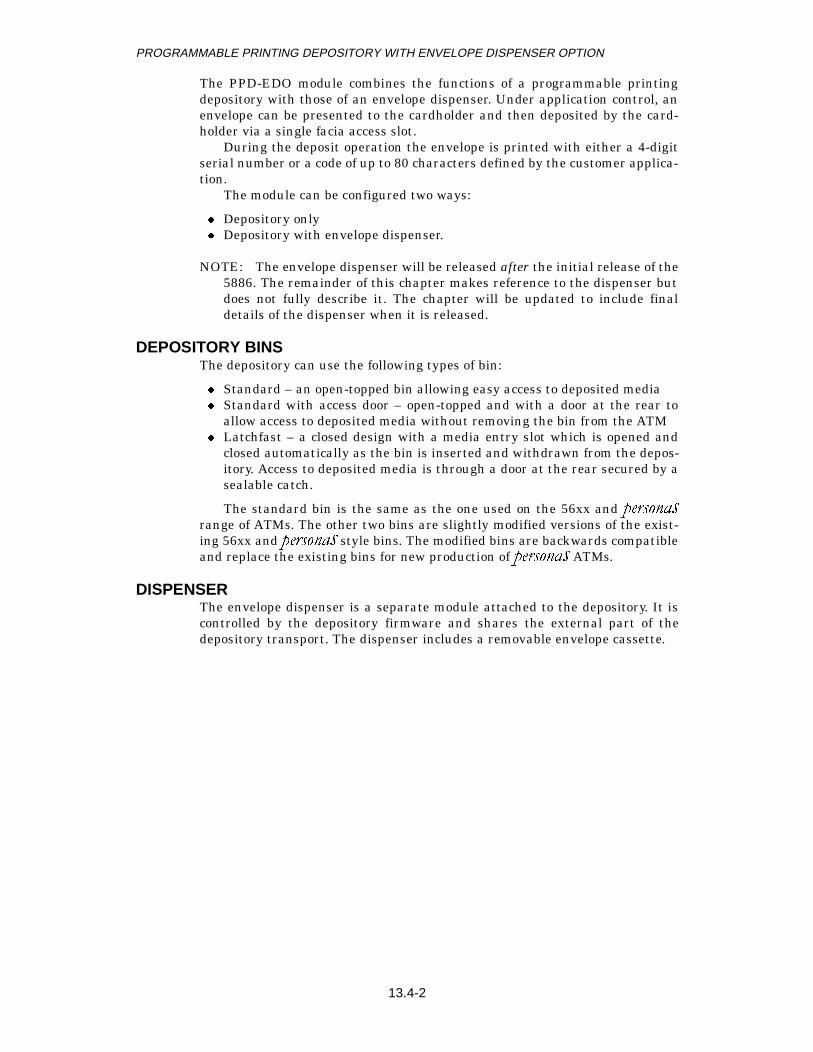
The PPD-EDO module combines the functions of a programmable printingdepository with those of an envelope dispenser. Under application control, anenvelope can be presented to the cardholder and then deposited by the card-holder via a single facia access slot.
During the deposit operation the envelope is printed with either a 4-digitserial number or a code of up to 80 characters defined by the customer applica-tion.
The module can be configured two ways:
z Depository onlyz Depository with envelope dispenser.
NOTE: The envelope dispenser will be released after the initial release of the5886. The remainder of this chapter makes reference to the dispenser butdoes not fully describe it. The chapter will be updated to include finaldetails of the dispenser when it is released.
DEPOSITORY BINSThe depository can use the following types of bin:
z Standard – an open-topped bin allowing easy access to deposited mediaz Standard with access door – open-topped and with a door at the rear to
allow access to deposited media without removing the bin from the ATMz Latchfast – a closed design with a media entry slot which is opened and
closed automatically as the bin is inserted and withdrawn from the depos-itory. Access to deposited media is through a door at the rear secured by asealable catch.
The standard bin is the same as the one used on the 56xx and SHUVRQDVrange of ATMs. The other two bins are slightly modified versions of the exist-ing 56xx and SHUVRQDV style bins. The modified bins are backwards compatibleand replace the existing bins for new production of SHUVRQDV ATMs.
DISPENSERThe envelope dispenser is a separate module attached to the depository. It iscontrolled by the depository firmware and shares the external part of thedepository transport. The dispenser includes a removable envelope cassette.
13.4-2

PROGRAMMABLE PRINTING DEPOSITORY WITH ENVELOPE DISPENSER OPTION
ENVELOPE SPECIFICATION
SizeThe size of envelope that can be used in the PPD-EDO is as follows:
z Length:z Minimum: 203mm (8.0in.)z Maximum: 254mm (10.0in.)
z Width:z Minimum: 99mm (3.90in.)z Maximum: 111mm (4.37in.).
PaperThe paper used to make the envelopes must have the following characteris-tics:
z Paper Weight: 77 to 100gm/m²z Burst Strength: 1.34 to 3.8kg/cm²z Percentage of filler material: ≤ 20%z Sizing COBB: 28gm/m²z Smoothness Bendtsen: 450mls/minz pH value: 5 to 7.
ConstructionThe recommended construction details for the envelopes are:
z Flap on the longest sidez Self-seal flap with adhesive along the complete length of the flapz No apertures or holes are permissible within a central band 54mm
(2.13in.) wide along the complete length of the envelope.
Moisture dependent seals are not recommended for ATM use.
ColourThe preferred background colour of the envelope within the print area iswhite. However, alternatives are acceptable provided that characters are legi-ble when produced by black or purple inks.
13.4-3

PROGRAMMABLE PRINTING DEPOSITORY WITH ENVELOPE DISPENSER OPTION
FUNCTIONAL DESCRIPTION
HARDWAREThe PPD-EDO hardware consists of the following parts:
z Security shutterz Transport systemz Envelope dispenser pick mechanismz Envelope cassettez Print modulez Depository binz Control modulez Sensors.
Security ShutterThe motorized security shutter is mounted on the facia and is controlled bythe depository firmware. Sensors mounted on the shutter assembly indicate tothe firmware whether the shutter is open or closed. Refer to chapter 12.3 fordetails of the shutter module.
Transport SystemThe transport system is a motorized, flat belt system designed to transport anenvelope of up to 12.7mm (0.5in.) thick from the access slot in the facia to thedepository bin. Sensors are placed at various points along the transport inorder to monitor the movement of an envelope.
When an envelope dispenser is fitted, the dispenser transport feeds theenvelope into the depository transport via a merge gate. The transport carriesthe envelope to the access slot where it is presented to the cardholder. If theenvelope is not removed, the transport will either drive it out through theaccess slot or retract it and move it to the depository bin.
The system consists of three main parts:
z The external transport, running from the shutter to the merge gatez The main transport, which carries the envelopes from the merge gate,
past the print head and into the depository binz The merge gate, which directs envelopes from the dispenser into the exter-
nal transport.
The merge gate is spring-loaded and, in its rest position, blocks the pathfrom the dispenser. During a dispense operation, the gate is pushed open bythe passing envelope and guides the envelope into the external transport.
Envelope DispenserThe envelope dispenser consists of two main components – a pick mechanismand transport, and an envelope cassette.
Pick MechanismThe pick mechanism is attached to the depository transport. The mechanismuses flat belts to drive an envelope into a narrow throat where a soft rollerensures that only a single envelope is picked.
13.4-4

PROGRAMMABLE PRINTING DEPOSITORY WITH ENVELOPE DISPENSER OPTION
CassetteThe cassette is designed to hold a stack of envelopes up to 150mm (5.90in.)high. The cassette can only be removed from the dispenser after first removingthe depository bin.
Print ModuleThe print module is a drop-on-demand ink-jet print head capable of generat-ing a matrix of dots to form characters on a passing envelope.
When the PPD-EDO is powered up but idle, the print head continually‘spits’ ink to keep the nozzles clear. If there is no envelope at the print positionthe ink hits an absorbent pad.
The spit rate depends on the ambient temperature as follows:
At power on, or following a reset, a power-up purge is carried out – eachnozzle spits 512 times with a gap of 850 microseconds between each spit.
A dummy deposit print is carried out an hour after either the last depositprint or the last dummy print. During a dummy print each nozzle spits 90times with a gap of 850 microseconds between each spit.
The absorbent ink pad is held in a pivoting plastic cradle accessible fromthe top of the mechanism.
Depository BinThe depository can be specified with one of three types of bin:
z Standardz Standard with access doorz Latchfast.
These are described in the section “GENERAL DESCRIPTION, DEPOSI-TORY BINS”.
Bin-Present MicroswitchIf the depository is specified with a latchfast bin, a bin-present microswitch isfitted. This is activated by the insertion and removal of the bin.
Bin CapacityThe capacity of the bins is dependent on the thickness of the envelopes depos-ited. The capacity of all bins is the same. Bin capacities are guaranteed for98 per cent of bin fills.
Temperature Spit Rate
Above 36°C (97.3°F) every 6 seconds
19°C to 36°C (67°F to 97.3°F) every 18 seconds
14°C to 19°C (57.5°F to 67°F) every 12 seconds
Below 14°C (57.5°F) every 6 seconds
Mix Ratio Capacity
100% Thin 500
95% Thin and 5% Mix 450
90% Thin and 10% Mix 400
75% Thin and 25%Mix 300
13.4-5
PROGRAMMABLE PRINTING DEPOSITORY WITH ENVELOPE DISPENSER OPTION
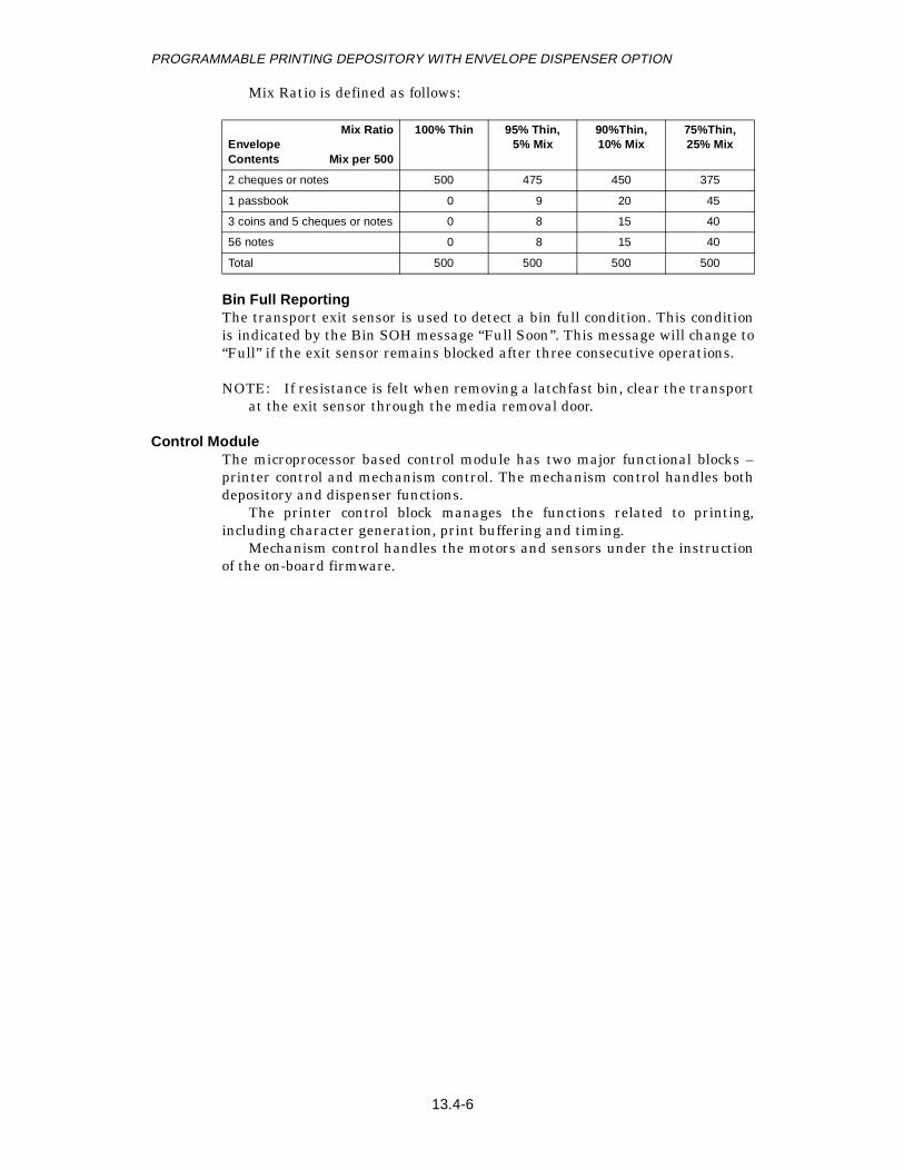
Mix Ratio is defined as follows:
Bin Full ReportingThe transport exit sensor is used to detect a bin full condition. This conditionis indicated by the Bin SOH message “Full Soon”. This message will change to“Full” if the exit sensor remains blocked after three consecutive operations.
NOTE: If resistance is felt when removing a latchfast bin, clear the transportat the exit sensor through the media removal door.
Control ModuleThe microprocessor based control module has two major functional blocks –printer control and mechanism control. The mechanism control handles bothdepository and dispenser functions.
The printer control block manages the functions related to printing,including character generation, print buffering and timing.
Mechanism control handles the motors and sensors under the instructionof the on-board firmware.
Mix RatioEnvelopeContents Mix per 500
100% Thin 95% Thin,5% Mix
90%Thin,10% Mix
75%Thin,25% Mix
2 cheques or notes 500 475 450 375
1 passbook 0 9 20 45
3 coins and 5 cheques or notes 0 8 15 40
56 notes 0 8 15 40
Total 500 500 500 500
13.4-6

PROGRAMMABLE PRINTING DEPOSITORY WITH ENVELOPE DISPENSER OPTION
SensorsThe control module monitors the hardware using infra-red sensors comprisingLEDs paired with photo-transistors. The LEDs and sensors are small, plasticassemblies hard-wired into the module harness. On the envelope depositoryitself there are four transport sensors, an anti-fish sensor and a timing disksensor. The entry, second and exit sensors comprise separate LED and photo-transistor modules. The other sensors are single opto-electronic switches.
If the depository uses a latchfast bin then a microswitch is fitted to act asa “bin-in” sensor.
In addition to the depository sensors, the control board monitors two sen-sors on the security shutter and the four sensors on the envelope dispenser (iffitted).
As the depository hardware and firmware is designed to be compatiblewith older ATM software, confusion can arise over the names of some sensors.The following table lists and briefly describes all the sensors in the depository.
NOTE: In other depositories used in the SHUVRQDV and 56XX ATMs the thirdsensor is the “At Print” sensor. See also “State Of Health Reporting”.
Name Alternative Names Description
Entry Detects envelopes entering the transport during deposits and being presented when dispensed.
Second Print or At Print This sensor is used to track the movement of envelopes and also to trigger printing during a deposit.
Merge Gate (See NOTE) Located on the Merge Gate mechanism, this sensor is used to track the movement of envelopes from the dis-penser transport into the external transport.
Exit Bin Full Detects envelopes leaving the transport.
Timing Disk Monitors rotation of the depository transport drive shafts.
Bin-In Detects the presence of a depository bin.
Anti-Fish Tamper or Fish Located on the Anti-Fish finger this sensor monitors the position of the finger.
13.4-7

PROGRAMMABLE PRINTING DEPOSITORY WITH ENVELOPE DISPENSER OPTION
Sensor Locations
EntryDuring a deposit, the shutter is closed only after the envelope clears the entrysensor.
During a dispense, the envelope is held at the end of the transport suchthat the entry sensor remains blocked until the cardholder takes the envelope.
SecondIn addition to position monitoring, the second sensor is used to initiate print-ing. During a deposit, printing starts as soon as an envelope clears the sensor.
Merge GateThe merge gate sensor detects the position of the gate by means of a flagattached to the gate. The gate is opened by the leading edge of an envelopeentering the gate from the dispenser transport and closes when the trailingedge clears the gate.
During deposit operations the merge gate remains closed.
ExitThe exit sensor is placed just beyond the end of the transport above the depos-itory bin. When an envelope clears this sensor it is assumed to have droppedinto the bin. A blocked exit sensor is interpreted as a Bin Full condition.
During deposit operations, the Bin Full condition becomes fatal on thethird successive occurrence of the exit sensor being blocked.
Entry
Second
MergeGate
Anti-FishFinger
Exit(Bin Full)
Bin-InMicroswitch
13.4-8

PROGRAMMABLE PRINTING DEPOSITORY WITH ENVELOPE DISPENSER OPTION
Timing DiskThe timing disk sensor monitors the rotation of one of the transport driveshafts. It provides the timing pulses that the controller uses to determineenvelope movement.
Anti-Fish FingerAn anti-fish finger is mounted between the merge gate and the print head andoperates the sensor using a flag attached to the finger. Normally the fingerhangs vertically but it is pushed up and out of the way as an envelope passes.
OPERATIONThe PPD-EDO is controlled by firmware residing on the controller PCB.
In normal operating mode the firmware controls and monitors the hard-ware in response to the following commands received from the customer appli-cation:
z Reset depositoryz Clear depositoryz Enable depositoryz Disable depositoryz Read replenishment informationz Increment serial numberz Reset TIz Enable TI reportingz Disable TI reporting.
The firmware also handles the SDC slave node Level-0 diagnostics andresponds to various Level-1 and Level-3 diagnostic commands. These aredescribed in the sections “LEVEL 0 DIAGNOSTICS”, “LEVEL 1 DIAGNOS-TICS” and “LEVEL 3 DIAGNOSTICS - TALLIES”.
Normal Operation Commands
Reset DepositoryThis command initializes the depository, resetting some error recovery countsand internal control flags.
Clear DepositoryThe purpose of the clear depository command is to check that the depository isclear and operable. The clear depository procedure is as follows:
1. The operation of the shutter is checked.2. The transport and bin-full sensors an interrogated.3. The printhead is checked for proper installation.4. The anti-fish finger is confirmed to be in its rest position.
If a transport blockage is detected, the shutter is operated and the trans-port driven for 10 seconds. If a jam is detected this is repeated 3 times.
If an envelope is detected passing the printhead (clearing the second sen-sor) an attempt is made to print the data last sent to the print buffer.
A bin overfill condition will be returned as fatal if it is the third consecu-tive occurrence of this state or a dispense command is received after the firstor second occurrence.
13.4-9

PROGRAMMABLE PRINTING DEPOSITORY WITH ENVELOPE DISPENSER OPTION
Enable DepositoryThe purpose of the enable depository command is to allow a cardholder todeposit an envelope, transport the envelope past the print head for markingand then move it to the deposit bin.
The enable depository procedure is as follows:
1. The transport is checked to see if it is clear and if a deposit can be made. 2. Relevant data is transferred to the print buffer and the print head is ena-
bled.3. If all is in order the shutter is opened and a solicited response of “OK” is
returned. The motor is started and a five minute timer is initiated for theenvelope to be deposited.
If all is not in order a solicited response of “Bad” is returned. 4. When an envelope enters the transport 10 seconds is allowed for it to
reach the bin before a jam is noted. 5. When the envelope clears the entry sensor the shutter closes. When the
envelope clears the second sensor the data is printed. 6. When the envelope clears the exit sensor and falls into the bin, the unso-
licited message of “Deposit Done” is returned.7. If at the end of a deposit the anti-fish finger is not in its rest position, a
“Tamper” error is returned.
NOTE: The five minute timer is used to avoid the possibility of the transportdrive motor’s thermal cutout operating. If this happened the depositorywould be disabled for 15 minutes.
Disable DepositoryThis command disables the depository, closing the shutter and stopping thetransport. If no envelope is in the transport, the unsolicited response to theEnable Deposit command is not sent.
If an envelope is in the transport when a Disable Depository command isreceived the transport will continue running until the envelope exits thetransport or a jam is detected.
z For a deposited envelope, the transport will continue to drive the envelopethrough to the depository bin
z If an envelope is being dispensed it will either be driven out through theshutter or it will be retracted and driven through to the depository bin.
NOTE: Whether an envelope is driven out or retracted is a configurationoption under customer control at the time of system build. The defaultconfiguration is to drive an envelope out.
Read Replenishment InformationThis command is used to obtain a report on the transport and timing disk sen-sors. The shutter is not checked and is reported as good.
Increment Serial NumberThis command is used either to increment the serial number held in NVRAMor to set the serial number to any desired new value when the appropriateextra data is sent with the command.
13.4-10

PROGRAMMABLE PRINTING DEPOSITORY WITH ENVELOPE DISPENSER OPTION
Reset TIThis command initialises the Tamper Indication firmware and disables TIreporting.
Enable TI reportingThis command enables TI reporting.
Disable TI reportingThis command disables TI reporting.
13.4-11

PROGRAMMABLE PRINTING DEPOSITORY WITH ENVELOPE DISPENSER OPTION
CIRCUIT DESCRIPTIONThe following description should be read in conjunction with the block dia-gram below and the schematic diagrams at the end of the chapter.
Block Diagram
SDC InterfaceThe SDC link is connected to the PPD-EDO control board through connectorJ1. The SDC signals are interfaced through two MAX1487 transceiver circuits(U1 and U2). SDC data is then passed to the processor (U16) which is an Intel8032 operating at 12 MHz.
The 8032 memory is implemented as 64K of external EPROM (U11),which contains the level 0 diagnostics, the link firmware and the module con-trol firmware, and 64K of external SRAM (U4 and U8) which contains thedata areas and can contain downloadable device firmware.
A programmable logic array (U9) performs the memory and I/O mapping.Memory mapped I/O for the processor consists of one Peripheral Interface
Adapter (PIA) 8255 (U21) and an Analog to Digital Converter (ADC) (U17).Processor outputs are provided through the PIA and processor inputs are pro-vided through the ADC.
AnalogMux
ADC
Bin-InSensor
CassetteLow
EnvelopePresentSensor
TransportSensors
Anti-FishSensor
Print Head
TemperatureMonitor
DepositoryMotor
Print HeadMonitor
Shutter
DispenserPresent
DispenserMotor
CassettePresent
MuxSelect
PortExpander
Processor
64KSRAM
64KEPROM
DepositoryTimingDisk
DispenserTimingDisk
BatteryBack Up
SDC
INT BINCOMMS
13.4-12

PROGRAMMABLE PRINTING DEPOSITORY WITH ENVELOPE DISPENSER OPTION
There are 16 analog inputs to the control board, which are multiplexed tothe ADC (U17). The multiplexer (U14 and U18) select codes are provided fromthe processor through PIA port A.
Non-volatile storage for SOH requirements is implemented by batterybacking the SRAM using a MAX691 power monitor circuit (U7) and a lithiumbattery.
Ink Jet Drive
Power ControlPower to the print head is provided on the control board and is controlled by apower transistor (Q3). Q3 will not pass the supply voltage to the print headuntil the POWER_RESET- signal is high. This prevents damage to the printhead when the ATM is powered on or off. Q3 is enabled by Q2 which is turnedon by a high level signal (provided by pin 7 of comparator U30) at its base.
The signal level at pin 7 of U30 goes high when the voltage at pin 5 risesabove the 2.5V reference voltage on pin 6.
The magnitude of the supply voltage to the print head will be equal to 24Vminus the emitter-collector drop across Q3. This drop will be typically 0.5V.
Print ControlPrint control information is sent from the control board to the flex circuitinterface board through connector J8.
Print data is fed to the printer through transistor arrays U38 and U39.Each transistor is turned on by a high level signal on the output of one of thetwelve 74LS02 three-input AND gates (U33, U34 and U35). There is one74LS02 for each ink jet.
Data is input to the 74LS02s from PIA port B and C along with anenable_print signal. A strobe signal pulses each gate in turn, enabling the noz-zles in the sequence 4, 10, 6, 12, 2, 8, 3, 9, 5, 11, 1, 7.
The strobe signal is derived as follows; if an enable_print signal is presentat the input of U37 (pin 11), the output of latch U37 enables a 4-bit counter(U32) which is permanently clocked by a 5 microsecond clock. The counter out-put is fed into two cascaded 3 to 8 decoders (U27 and U28). The strobing isturned off by the seventh bit from the decoder (U27) which is fed back throughU22 to reset the latch which disables the counter.
The 5 microsecond clock signal is derived from the ALE signal from theprocessor. The ALE frequency is 1/6 of the oscillator frequency, that is, 2 MHz.This signal is divided by a factor of ten by a 74LS90 (U31) giving a 5 microsec-ond clock signal.
Print Head MonitorTwo of the twelve printhead contacts (outputs from the MC1413 driver
transistors) are processed to determine if the printhead has been correctlyinstalled, or is faulty.
If either printhead contact line INK2 (U38 pin 10) or INK7 (U38 pin 13)give a reading of less than 4V, this indicates that a printhead is either miss-ing, not installed correctly or is faulty.
The printhead monitor provides a HEAD_LED signal which turns on aLED located on the flexible print head interface board.
13.4-13
PROGRAMMABLE PRINTING DEPOSITORY WITH ENVELOPE DISPENSER OPTION
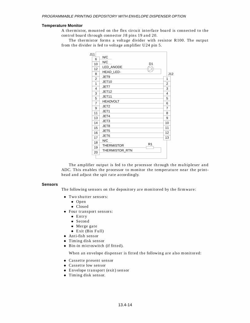
Temperature MonitorA thermistor, mounted on the flex circuit interface board is connected to thecontrol board through connector J8 pins 19 and 20.
The thermistor forms a voltage divider with resistor R100. The outputfrom the divider is fed to voltage amplifier U24 pin 5.
The amplifier output is fed to the processor through the multiplexer andADC. This enables the processor to monitor the temperature near the print-head and adjust the spit rate accordingly.
SensorsThe following sensors on the depository are monitored by the firmware:
z Two shutter sensors:z Openz Closed
z Four transport sensors:z Entryz Secondz Merge gatez Exit (Bin Full)
z Anti-fish sensorz Timing disk sensorz Bin-in microswitch (if fitted).
When an envelope dispenser is fitted the following are also monitored:
z Cassette present sensorz Cassette low sensorz Envelope transport (exit) sensorz Timing disk sensor.
6
10
12
8
2
1
4
3
5
7
9
11
13
14
15
16
17
18
19
20
1
2
3
4
5
6
7
8
9
10
11
12
13
N/C
N/C
LED_ANODE
HEAD_LED-
JET9
JET10
JET7
JET12
JET11
HEADVOLT
JET2
JET1
JET4
JET3
JET8
JET5
JET6
N/C
THERMISTOR
THERMISTOR_RTN
R1
D1
J12
J11
13.4-14

PROGRAMMABLE PRINTING DEPOSITORY WITH ENVELOPE DISPENSER OPTION
NOTE: The firmware registers the presence of the envelope dispenser whenthe dispenser harness is plugged in – the harness has a shorting loopbetween pins 13 and 14 of connector J5.
Transport and Anti-Fish SensorsThe transport and anti-fish sensors are all opto-electronic. They are allconnected to the control board through connector J6. A clear sensor returns avoltage of between 3V and 5V to the control board on the SEN lines and ablocked sensor returns a voltage close to 1V. If the sensor clear voltage isbelow 1.25V, the sensor is either out of alignment or needs cleaning.
The control board controls the sensors by turning the supply voltage to theLEDs on and off. The LED voltage is supplied by a MOSFET transistor (U23).The magnitude of the LED supply voltage is approximately 5V. The LED volt-age is cut off by a low level signal on bit 6 of PIA U2 port C. This signal feedsthe gate of the MOSFET transistor U23 via buffers (U29). A high will turn offthe MOSFET.
Timing Disk SensorThe timing disk sensor is connected to the control board through connector J6.Its operation is different from that of the transport sensors in that thephototransistor output is fed directly into a comparator (U36), which convertsthe signal into a TTL voltage. The TTL signal is fed directly to themicroprocessor interrupt port P3.
Shutter SensorsThe shutter sensors are driven from the shutter control board and return logicsignals (SHUTTER_LOCK and SHUTTER_OPEN) to the control boardthrough connector J7.
Bin-In SensorA depository with a latchfast bin will have an optional bin-in microswitch con-nected to J4.
Motor ControlThe depository motor is controlled by the MOTOR_ON signal (PIA U21 port Cbit 4). A low signal will turn on the motor driver U10.
13.4-15
PROGRAMMABLE PRINTING DEPOSITORY WITH ENVELOPE DISPENSER OPTION
SERVICE AIDSThe following sections contain information about the servicing and operatingprocedures of the depository.
TEST TOOLSNone.
STRAPPINGThere is an eight pole switch pack, U6, used for level 0 diagnostic testing.Refer to the section “LEVEL 0 DIAGNOSTICS”.
For normal operation all switches must be off (up, away from the board).
ADJUSTMENTS
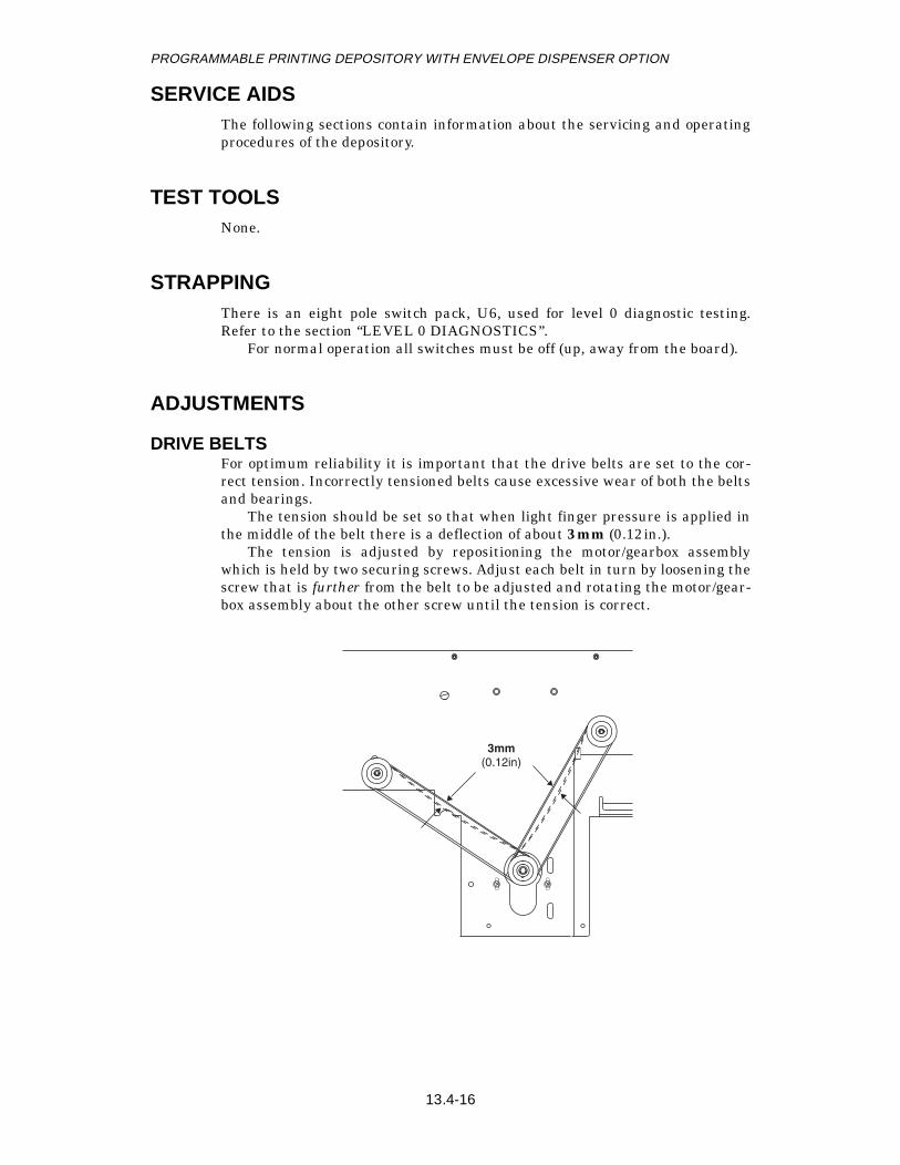
DRIVE BELTSFor optimum reliability it is important that the drive belts are set to the cor-rect tension. Incorrectly tensioned belts cause excessive wear of both the beltsand bearings.
The tension should be set so that when light finger pressure is applied inthe middle of the belt there is a deflection of about 3mm (0.12in.).
The tension is adjusted by repositioning the motor/gearbox assemblywhich is held by two securing screws. Adjust each belt in turn by loosening thescrew that is further from the belt to be adjusted and rotating the motor/gear-box assembly about the other screw until the tension is correct.
3mm
(0.12in)
13.4-16

PROGRAMMABLE PRINTING DEPOSITORY WITH ENVELOPE DISPENSER OPTION
PRINT HEAD REPLACEMENTThe print head must be replaced with a Hewlett Packard (HP) ink jet printhead cartridge, HP Part No. 92261A, (NCR Part No. 009-0005775).
The replacement interval is:
z Applications with SOH – every six months, or sooner if the SOH message“End of Life Reached, Replace Print Head Now” is displayed
z Applications without SOH – every three months.
Replace the print head as follows:
1. Open the security enclosure.2. Remove the deposit bin.3. Push the green latch to the right and fully rack out the depository.4. Check the ‘use before’ date on the packaging of the replacement print head
and if satisfactory, remove the packaging and purge the print head (see“Purging” below).
5. Push the print head retaining latch down. If the terminal is powered up,the head LED will light up.
6. Lower the print head slightly to release the locating pins from the carrierthen slide out the print head.
7. Insert the new, purged print head into the carrier so the locating pinsengage with the holes in the carrier.
8. Close the print head retaining latch by pulling it up. When the head is cor-rectly positioned the LED will go out. Do not use excessive pressure – ifthe LED does not go out, remove and refit the head.
9. Rack in the depository until the depository latch is engaged.10. Replace the deposit bin.11. Using level 1 diagnostics perform a Deposit and Character Generation
test and verify print quality.
1
2
13.4-17

PROGRAMMABLE PRINTING DEPOSITORY WITH ENVELOPE DISPENSER OPTION
PurgingThe only time a print head should be purged is prior to its initial installation.
NOTE: If after installation there are any fail to print problems that may becured by purging, the print head must be replaced.
Purge the print head as follows:
1. Hold the cartridge so that the print face is horizontal.2. Insert a metal probe, such as a straightened paper clip, into the hole in the
base of the plastic casing.
3. Keeping the print face horizontal, press the probe gently against the blad-der until a droplet of ink covers most of the print face. Normally inkappears in three drops – release the pressure when the drops join up.
13.4-18

PROGRAMMABLE PRINTING DEPOSITORY WITH ENVELOPE DISPENSER OPTION
4. Remove the probe and allow the ink to absorb slowly back into the printhead for approximately 30 seconds.
5. Wipe off any excess ink with a lint free tissue.
Ink Pad RepositioningAt every service call the absorbent ink pad should be checked and, if neces-sary, repositioned to bring a fresh area into use.
13.4-19

PROGRAMMABLE PRINTING DEPOSITORY WITH ENVELOPE DISPENSER OPTION
LUBRICATION
GENERAL INSTRUCTIONSThe following general instructions must be observed:
z Use clean lubricant from properly labelled containersz Avoid excessive lubrication – apply only enough to provide a thin coating
on the entire bearing area or surfacez All parts to be lubricated should be free from dust, corrosion and metal
chipsz NCR lubricants should be thoroughly mixed before use – uniform consist-
ency and colour denote adequate mixing.
LUBRICATION POINTSWhen the module is assembled or reworked the bearings and spring anchorpoints shown below require lubrication with NCR No.1 Grease.
TROUBLESHOOTINGNone.
LEVEL 0 DIAGNOSTICSWhen the control board is powered up or receives a reset command, part of thefirmware known as the Execution Diagnostic Subsystem (EDS) automaticallycarries out a series of tests under the control of the Execution Processor.
The tests run in start-up mode, that is, they execute in sequence withoutoperator intervention. The tests check the basic functions of the board – suchas the operation of the processor, EPROM and SRAM. Limited testing is alsocarried out on the ADC. If start-up is successful, control is passed to the depos-itory application firmware. Test results are displayed on a bank of four LEDs.
The EDS may also be controlled via a Remote Diagnostics Interface con-nector which provides access to the LED and Reset signals.
An 8-pole switch pack is provided to run selected tests. These are SDCslave node tests and details of these can be found in Chapter 2.3. One of these
A
A
A
A
AA
A
A
B B
B B B
A: Self Aligning BearingsB: Spring Anchor PointsC: Bearings on Link Arms
C C
CC C
13.4-20

PROGRAMMABLE PRINTING DEPOSITORY WITH ENVELOPE DISPENSER OPTION
tests can be used to clear NVRAM and so force the ATM to download thedepository firmware following the next system reset.
NOTE: The EDS does not test the sensor circuits. These can be tested fullyusing Level 1 Diagnostics.
INTERFACESThere are two interfaces to the Execution Diagnostics Subsystem:
z On-board LEDsz Hard-wired Remote Diagnostic Interface (RDI).
LED Interface
The on-board LEDs are used to display the test number of the test being runand the error code if a test fails. The LEDs display the codes as binary num-bers:
The following sections refer to the codes using hexadecimal numbers, forexample, test result BH (decimal 11) is represented by:
All test codes have numbers 7H or lower so LED 4 is always off during atest. All error codes have numbers 8H or higher so LED 4 is always on follow-ing a failure. A successful test result is always number 0H, i.e. all LEDs off.
On successful completion of a test the EDS jumps to the next test withoutdisplaying a pass code. If a test fails, the EDS displays the test ID for one sec-ond and then the error code for two seconds. If an error occurs in the routerthen the LEDs do not flash but stay on permanently.
LED 1 2 3 4
least - - - - - significant bit - - - - - most
decimal value: 1 2 4 8
LED 1 2 3 4
Result BH 1 1 0 1
1 2 3 4
Switch Pack
RemoteDiagnostics
Interface
LEDs
13.4-21

PROGRAMMABLE PRINTING DEPOSITORY WITH ENVELOPE DISPENSER OPTION
Remote Diagnostic Interface (RDI)The EDS may be controlled via the RDI. The RDI is a hardware interfacewhich echoes the information on the LEDs and may also be used to drive theboard reset line.
START-UP MODE
Test SequenceAt start-up the following sequence of events takes place:
z Call initialization codez Execute the tests in the following order:
z Test 1H – Microcontroller confidence and EPROM sumcheckz Test 2H – SRAM data testz Test 3H – SRAM address test
z Clear all SRAM to zeroz Pass control to the application firmware.
Test Router
PurposeThe Test Router controls the execution of the depository Execution Processordiagnostics.
Test Results
NoteThe error codes displayed by the router do not flash.
Test 1H - Microcontroller Confidence and EPROM Sumcheck
PurposeTo test the microcontroller (MCU), check that the contents of the EPROM arevalid and also check the functionality of the A/D converter.
Test Results
LEDs Status
0H Start-up passed
EH CPU quick check failed
FH CPU probably stuck at reset
LEDs Status
0H Pass
8H MCU ALU fault
9H MCU RAM fault
AH MCU TIMER fault
BH MCU interrupt control register fault
CH MCU serial control register fault
DH EPROM sumcheck fail
EH A/D converter fail
13.4-22

PROGRAMMABLE PRINTING DEPOSITORY WITH ENVELOPE DISPENSER OPTION
Notes
1. On power-up the LEDs should indicate FH. If the LEDs stay at FH thenthe MCU is possibly held in the RESET type state. If LEDs hang-up withBH then initialization is not taking place.
2. The top two bytes of EPROM are reserved for Level 0 Diagnostics. Thechecksum value is stored there.
Test 2H - SRAM Data
PurposeThis test checks all SRAM that is testable.
Test Results
NoteThe depository control board is populated with only one SRAM.
Test 3H - SRAM Address
PurposeThis test checks the whole of SRAM for hardware faults.
Test Results
SELECTED TEST MODEIn selected test mode an 8-pole switch pack is used to run selected tests. Theseare all SDC slave node tests and details can be found in Chapter 2.3.
To clear NVRAM, use the following test.
Test 4H – Test All RAM Data (Clear NVRAM)This test will clear all the data in NVRAM, including all level 3 diagnostics(tallies), and so should only be carried out when it is necessary to update orreload the depository firmware.
LEDs Status
0H Pass
8H Internal data error in lower part of SRAM (0 – 3FFFH)
9H Internal data error in upper part of SRAM (4000H – 7FFFH)
AH External data fault on lower part of SRAM (0 – 3FFFH)
BH External data fault on upper part of SRAM (4000H – 7FFFH)
LEDs Status
0H Pass
8H Data error while verifying 00H write
9H Data error while verifying 0FFH write - at address 000H
AH SRAM address bus error in lower 8 lines
BH SRAM address bus error in upper 8 lines
EH Chip select fault
13.4-23

PROGRAMMABLE PRINTING DEPOSITORY WITH ENVELOPE DISPENSER OPTION
Switch Setting
Test Result
LEVEL 1 DIAGNOSTICS
DEPOSITORYThe level 1 diagnostics tests available for the envelope depository are:
z Deposit and Print Dataz Deposit and Print Serial No.z Shutter/Sensor Status z Increment Serial Number z Clear Transport z Disable Depositoryz SDC Turnaroundz Run-to-Run.
If a latchfast bin is fitted an additional test is available on the enve-lope depository TI menu:
z Tamper Indication.
Looping is allowed on all tests.
NOTE: The M-DATA and M-STATUS codes for the tests are listed after thetest descriptions.
TEST DESCRIPTIONS
Deposit and Print DataThe Deposit and Print Data test is similar to a normal deposit operation. Thedepository is enabled and the operator is prompted to insert an envelope. Thismust be done within 10 seconds.
If an envelope is deposited the ASCII characters LDTX are printed on it20 times as it is transported to the bin.
At the end of the test the operator is prompted to verify acceptability ofprint position and quality.
The serial number is not incremented during this test. The tallies are notincremented and error recovery is not attempted.
SW1 SW2 SW3 SW4 SW5 SW6 SW7 SW8
0 0 1 0 0 0 0 1
LEDs Status
0H Pass
8H Internal data fault in lower SRAM
9H Internal data fault in upper SRAM
AH External data fault in lower SRAM
BH External data fault in upper SRAM
13.4-24

PROGRAMMABLE PRINTING DEPOSITORY WITH ENVELOPE DISPENSER OPTION
Deposit and Print Serial No.The Deposit and Print Serial Number test is similar to a normal deposit oper-ation. The depository is enabled and the operator is prompted to insert anenvelope. This must be done within 10 seconds.
If an envelope is deposited the serial number is printed on it 10 times as itis transported to the bin.
At the end of the test the operator is prompted to verify acceptability ofprint position and quality.
The serial number is incremented during this test. The tallies are notincremented and error recovery is not attempted.
Shutter/Sensor StatusThe Shutter/Sensor Status test opens and closes the shutter and then returnsthe status of the following sensors.
z Shutter sensorsz Entry, second, merge gate and bin-full (exit) sensorsz Timing Disk sensor.
Increment Serial NumberThe Increment Serial Number test increments the stored serial number byone.
This test can only be verified by performing two successful “Deposit andPrint Serial No.” tests – one carried out before the test and one after. Theserial numbers on the two envelopes should then be compared.
Clear TransportThe Clear Transport test checks that the depository is clear and operable. Theclear transport procedure:
1. Checks the shutter operation.2. Interrogates the transport sensors.3. Checks the printhead is properly installed.4. Checks the anti-fish finger is in its normal position.
If a transport blockage is detected, the shutter is operated and the trans-port driven for 10 seconds. If an envelope is detected passing the printhead anattempt is made to print the data last sent to the print buffer.
A bin overfill condition will be returned as fatal if it is the third consecu-tive occurrence of this state.
NOTE: A GOOD status is returned if there is no blockage detected.
Disable DepositoryThe Disable Depository test disables the depository, closing the shutter andstopping the transport.
If an envelope is in the transport when a Disable Depository command isreceived the transport will continue running until the envelope exits thetransport or a jam is detected.
z For a deposited envelope, the transport will continue to drive the envelopethrough to the depository bin
z If an envelope is being dispensed it will either be driven out through theshutter or it will be retracted and driven through to the depository bin.
13.4-25

PROGRAMMABLE PRINTING DEPOSITORY WITH ENVELOPE DISPENSER OPTION
NOTE: Whether an envelope is driven out or retracted is a configurationoption under customer control at the time of system build. The defaultconfiguration is to drive an envelope out.
SDC TurnaroundThe SDC Turnaround test carries out a turnaround test between the SDCservice and the module.
Run-to-RunThe Run-to-Run test automatically performs, in sequence, the following tests:
z Clear Transportz Shutter/Sensor Statusz Deposit and Print Serial Number.
Tamper IndicationThis test returns the status of the envelope depository TI as M_DATA.
M_STATUSThe M_STATUS codes returned for the envelope depository are:
M_DATABytes 0, 1 and 2 are bit encoded and the conditions are true when the appro-priate bit is high (logic 1).
Byte 0 – Transport:
M_STATUS Meaning
00 No error.
01 Transport jam.
02 Transport jam and shutter jammed open.
03 Transport jam and shutter jammed closed.
04 Shutter jammed open.
05 Shutter jammed closed.
06 Transport sensor failure.
07 Communications failure.
11 Depository bin overfill.
13 Timing disk failure.
15 Transport motor failure.
50 Anti-fish finger not in rest position.
52 Print head removed.
55 Interlock failure.
146 SDC link failure.
Bit 0 = 1 Entry sensor blocked
Bit 1 = 1 Second sensor blocked
Bit 2 = 1 Exit sensor blocked
Bit 3 = 1 Entry sensor failed or envelope not seen
Bit 4 = 1 Second sensor failed or envelope not seen
Bit 5 = 1 Merge gate open
Bit 6 = 1 Bin overfill
Bit 7 = 1 Bin absent
13.4-26

PROGRAMMABLE PRINTING DEPOSITORY WITH ENVELOPE DISPENSER OPTION
Bits 3 to 5 combined with bits 0 to 2 indicate whether the sensor failedindicating blocked (indicated something that was not there) or indicating clear(failed to detect something that was there).
Bit 6, bin overfill, will be high after the third consecutive occurrence of theexit sensor being blocked.
Byte 1 – Shutter Sensors
Byte 2 = Module/Printhead
Bytes 3 to 10These bytes correspond to the following sensors:
All the above sensors share a common set of bit values:
M_DATA (DEPOSITORY TI)The M_DATA returned for the envelope depository TI are:
Bit 0 = 1 Jammed shut
Bit 1 = 1 Jammed open
Bits 2 to 7 Not used
Bits 1 to 3 Not used
Bit 4 = 1 Too many dots printed – printhead near end of life
Bits 5 and 6 Not used
Bit 7 = 1 Bin overfill
Byte Sensor
3 Anti-Fish Finger
4 Shutter Open
5 Shutter Closed
6 Entry
7 Second
8 Merge Gate
9 Exit
10 Timing Disk
Bit 0 = 1 Sensor clear
Bit 1 = 1 Sensor blocked
Bit 2 = 1 Sensor failed indicating clear
0 TI on, bin in
1 TI on, bin out
2 TI off, bin in
3 TI off, bin out
13.4-27

PROGRAMMABLE PRINTING DEPOSITORY WITH ENVELOPE DISPENSER OPTION
LEVEL 3 DIAGNOSTICS - TALLIESThe tallies are incremented by one when the appropriate condition occurs dur-ing normal use and some diagnostic tests.
DEPOSITORYThe envelope depository tallies are as follows:
STATE OF HEALTH REPORTINGAny State of Health (SOH) messages associated with the PPD-EDO are dis-played on the rear operator panel. In addition to identifying a fault, the SOHmessage will give details of any corrective action. SOH messages are only dis-played at the top level menu.
In order to maintain compatibility with previous hardware and applica-tions, the SOH messages have not been updated to reflect the new PPD-EDOhardware. For the depository, the following messages are misleading:
In both these cases the “At Print” sensor should be read as the “MergeGate” sensor.
Tally number Tally Mnemonic Description
03H DRVTRANS Times the transport is driven.
04H DEPOSJAM Jams detected in the transport.
05H SENSFAIL Sensor failures.
06H SHUTOPER Shutter operations.
07H SHUTTJAM Shutter jams.
08H ENABDEPO Depository enabled.
09H DEPNTDON Deposit not done.
0AH (reserved) (reserved)
0BH (reserved) (reserved)
0CH (reserved) (reserved)
0DH (reserved) (reserved)
0EH (reserved) (reserved)
0FH DEPOSDON Deposits done.
10H BINOVRFL Bin overfill detected
SOH Code: Meaning:
303H Transport jammed at “At Print” sensor.
304H Average number of successful operations between jams at “At Print” sensor below threshold.
13.4-28

PROGRAMMABLE PRINTING DEPOSITORY WITH ENVELOPE DISPENSER OPTION
CABLE AND CONNECTOR DATA
INTERCONNECTION DIAGRAM
J8 J12 J11Flex I/F
PrintHead
J3
J2
J4
J6
J5
DepositoryMotor
ShutterMotor
DepositoryTiming Disk
ShutterSensors
Anti-FishFinger
DepositoryTransport
DispenserMotor
ShutterControlBoard
Open
Locked
Entry
Second (Print)Merge Gate
Exit (Bin Full)
Bin-In
DispenserSensors
Cassette Present
Cassette Low
Envelope Present
DispenserTiming Disk
Latchfast Bin Only
PP
D-
ED
OC
on
tro
lP
CB
13.4-29

PROGRAMMABLE PRINTING DEPOSITORY WITH ENVELOPE DISPENSER OPTION
CONNECTOR PINOUTS
J1 – SDC I/F
J2 – Power
J3 – Motors
J4 – Bin-In
N/C 1 2 N/C
DATA+ 3 4 DATA-
RESET+ 5 6 RESET-
N/C 7 8 N/C
SIG_REF 9 10 N/C
GND 1 9 +5V
GND 2 10 N/C
N/C 3 11 N/C
GND 4 12 +24V
SHUTTER_LOCK 5 13 N/C
GND 6 14 SHUT_MOT_ON-
SHUTTER_OPEN 7 15 N/C
CHASSIS GND 8 16 +24V_I/L
ENV_DC_B 1 3 PPD_DC_A
ENV_DC_A 2 4 PPD_DC_B
TI_BIN_PRES- 1
GND 2
GND 3
13.4-30

PROGRAMMABLE PRINTING DEPOSITORY WITH ENVELOPE DISPENSER OPTION
J5 – Envelope Dispenser I/F
J6 – Sensors
J7 – Facia Interface
ENV_EXIT_LED 1 2 GND
ENV_EXIT_SEN 3 4 +5V
ENV_TIM_LED 5 6 GND
ENV_TIM_SEN 7 8 GND
ENV_CASS_LOW- 9 10 GND
ENV_CASS_PRES- 11 12 GND
ENV_DISP_PRES- 13 14 GND
N/C 15 16 N/C
PPD_ENTRY_LED 1 2 GND
PPD_ENTRY_SEN 3 4 +5V
PPD_PRINT_LED 5 6 GND
PPD_PRINT_SEN 7 8 +5V
PPD_TIM_LED 9 10 GND
PPD_TIM_SEN 11 12 GND
PPD_GATE_LED 13 14 GND
PPD_GATE_SEN 15 16 GND
PPD_FISH_LED 17 18 GND
PPD_FISH_SEN 19 20 GND
PPD_BIN_OVER_LED 21 22 GND
PPD_BIN_OVER_SEN 23 24 GND
SHUT_MOT_ON- 1 2 GND
SHUTTER_LOCK 3 4 GND
SHUTTER_OPEN 5 6 GND
N/C 7 8 GND
13.4-31

PROGRAMMABLE PRINTING DEPOSITORY WITH ENVELOPE DISPENSER OPTION
J8 – Ink Jet Print Head
J9 – Remote Diagnostics
IJET10- 1 2 IJET9-
IJET12- 3 4 IJET7-
IJET11- 5 6 N/C
HEADVOLT 7 8 HEAD_LED-
IJET2- 9 10 N/C
IJET1- 11 12 +5V
IJET4- 13 14 IJET3-
IJET8- 15 16 IJET5-
IJET6- 17 18 N/C
THERM 19 20 THERM_RET
+5V 1 2 RDI_RESET-
SWITCH1 3 4 N/C
SWITCH2 5 6 LED1
SWITCH3 7 8 LED2
SWITCH4 9 10 N/C
SWITCH5 11 12 LED3
SWITCH6 13 14 LED4
SWITCH7 15 16 N/C
SWITCH8 17 18 N/C
GND 19 20 GND
13.4-32

PROGRAMMABLE PRINTING DEPOSITORY WITH ENVELOPE DISPENSER OPTION
CABLING INFORMATION
Sensor Harness
Bin-In Switch Harness
PP
D-E
DO
Con
trol
Boa
rd
Entry LED1
2
3
4
5
6
7
8
9
10
11
12
13
14
15
16
17
18
19
20
Entry Sensor
2nd (Print) LED
2nd (Print)
Timing Disk
Merge Gate
Anti-Fish
Bin Full (Exit)
21
22
23
24
J6
ENTRY_LED
RTN
ENTRY_SENSOR
+5V
2ND_LED
RTN
2ND_SENSOR
+5V
TIMING_LED
RTN
TIMING_SENSOR
RTN
GATE_LED
RTN
GATE_SENSOR
RTN
FISH_LED
RTN
FISH_SENSOR
RTN
BIN_FULL_LED
RTN
BIN_FULL_SENSOR
RTN
Sensor
Finger
PP
D-E
DO
Con
trol
Boa
rd
1
3
J4
TI_BIN_PRES-
RTN
NO
C
Bin-inMicro-switch
13.4-33

PROGRAMMABLE PRINTING DEPOSITORY WITH ENVELOPE DISPENSER OPTION
Motor Harness
Power and Shutter Harness
SDC Harness
PP
D-E
DO
Con
trol
Boa
rd
1
2
3
4
J3
ENV_DC_B
ENV_DC_A
PPD_DC_A
PPD_DC_B
ED_ADPTR_P1
DepositoryMotor
ENV_DC_B
ENV_DC_A1
2
1
2DispenserMotor
PP
D-E
DO
Con
trol
Boa
rd
1
2
3
4
5
6
7
8
J2
+5V RTN
+24V RTN
SHUTTER LOCK
RTN
SHUTTER OPEN
+24V I/L RTN
1
2
3
4
5
6
7
8
POWER_J1
9
10
11
12
13
14
15
16
+5V
+24V
RTN
SHUT MOT ON-
RTN
+24V I/L
9
10
11
12
13
14
15
16
PP
D-E
DO
Con
trol
Boa
rd
1
2
3
4
5
6
7
8
J1
DATA+
DATA-
RESET+
RESET-
1
2
3
4
5
6
7
8
SDC_J1
9
10
SIG REF 9
10
13.4-34

PROGRAMMABLE PRINTING DEPOSITORY WITH ENVELOPE DISPENSER OPTION
Print Head Harness
PP
D-E
DO
Con
trol
Boa
rd
J8
Prin
t Hea
d F
lex
I/F B
oard
1
2
4
5
7
8
9
10
11
12
13
14
15
16
17
18
19
20
3
6
1
2
4
5
7
8
9
10
11
12
13
14
15
16
17
18
19
20
3
6
J12
IJET10-
IJET9-
IJET12-
IJET7-
IJET11-
N/C
HEADVOLT
HEAD_LED-
IJET2-
N/C
IJET1-
+5V
IJET4-
IJET3-
IJET8-
IJET5-
IJET6-
N/C
THERM
THERM_RET
13.4-35

PROGRAMMABLE PRINTING DEPOSITORY WITH ENVELOPE DISPENSER OPTION
SCHEMATICSThe PCB layout is shown below. The schematic diagrams are on the following10 pages.
PCB Layout Diagram – Sheet 1 of 1
13.4-36

PROGRAMMABLE PRINTING DEPOSITORY WITH ENVELOPE DISPENSER OPTION
Schematic Diagram – Sheet 1 of 11
13.4-37

PROGRAMMABLE PRINTING DEPOSITORY WITH ENVELOPE DISPENSER OPTION
Schematic Diagram – Sheet 2 of 11
13.4-38

PROGRAMMABLE PRINTING DEPOSITORY WITH ENVELOPE DISPENSER OPTION
Schematic Diagram – Sheet 3 of 11
13.4-39

PROGRAMMABLE PRINTING DEPOSITORY WITH ENVELOPE DISPENSER OPTION
Schematic Diagram – Sheet 4 of 11
13.4-40

PROGRAMMABLE PRINTING DEPOSITORY WITH ENVELOPE DISPENSER OPTION
Schematic Diagram – Sheet 5 of 11
13.4-41

PROGRAMMABLE PRINTING DEPOSITORY WITH ENVELOPE DISPENSER OPTION
Schematic Diagram – Sheet 6 of 11
13.4-42

PROGRAMMABLE PRINTING DEPOSITORY WITH ENVELOPE DISPENSER OPTION
Schematic Diagram – Sheet 7 of 11
13.4-43

PROGRAMMABLE PRINTING DEPOSITORY WITH ENVELOPE DISPENSER OPTION
Schematic Diagram – Sheet 8 of 11
13.4-44

PROGRAMMABLE PRINTING DEPOSITORY WITH ENVELOPE DISPENSER OPTION
Schematic Diagram – Sheet 9 of 11
13.4-45

PROGRAMMABLE PRINTING DEPOSITORY WITH ENVELOPE DISPENSER OPTION
Schematic Diagram – Sheet 10 of 11
13.4-46

PROGRAMMABLE PRINTING DEPOSITORY WITH ENVELOPE DISPENSER OPTION
Schematic Diagram – Sheet 11 of 11
13.4-47

PROGRAMMABLE PRINTING DEPOSITORY WITH ENVELOPE DISPENSER OPTION
13.4-48