Program Statementd1vmz9r13e2j4x.cloudfront.net/NET/misc/CapitolHvacPlan-3205.pdf · Program...
55
Program Statement for Nebraska State Capitol HVAC Replacement Project OCC Project No. 201405 Lincoln, Nebraska May 2015 BVH Architects 440 N 8 th Street, Suite 100 Lincoln Nebraska 68508 BVH project # L14077 Alvine Engineering 1800 “O” Street Lincoln Nebraska 68508 Wiss Janney Elstner Associates, Inc. 10 South LaSalle St., Suite 2600, Chicago Illinois 60603 Mark 1 Restoration Company 1021 Maryland Avenue Dolton Illinois 60419-2225
Transcript of Program Statementd1vmz9r13e2j4x.cloudfront.net/NET/misc/CapitolHvacPlan-3205.pdf · Program...
Program Statement for
Nebraska State Capitol
HVAC Replacement Project OCC Project No. 201405
Lincoln, Nebraska
May 2015
BVH Architects 440 N 8th Street, Suite 100
Lincoln Nebraska 68508
BVH project # L14077
Alvine Engineering 1800 “O” Street
Lincoln Nebraska 68508
Wiss Janney Elstner Associates, Inc. 10 South LaSalle St., Suite 2600,
Chicago Illinois 60603
Mark 1 Restoration Company 1021 Maryland Avenue
Dolton Illinois 60419-2225
Program Statement May 2015
Nebraska State Capitol | HVAC Replacement ProjectNebraska State Capitol | HVAC Replacement ProjectNebraska State Capitol | HVAC Replacement ProjectNebraska State Capitol | HVAC Replacement Project
Nebraska State CapitolNebraska State CapitolNebraska State CapitolNebraska State Capitol
BVH Architects in association w/ Alvine Engineering, Wiss, Janney, Elstner Associates and Mark 1 Restoration Page i
Table of Table of Table of Table of ContentsContentsContentsContents I.I.I.I. IntroductionIntroductionIntroductionIntroduction
A. Background and History of the Project to Date B. Project Description C. Purpose, Goals and Objectives
II.II.II.II. Justification of the ProjectJustification of the ProjectJustification of the ProjectJustification of the Project
A. Data which supports the funding request 1. Nebraska State Capitol Restoration Master Plan 2. Legislative Bill LB 905
B. Alternatives Considered
III.III.III.III. Location and Site ConsiderationsLocation and Site ConsiderationsLocation and Site ConsiderationsLocation and Site Considerations
A. General Site Information 1. County 2. Town and Campus 3. Proposed Site
a. Existing Capitol Site Plan b. Existing Capitol Complex and Environs
B. Statewide Building Inventory C. Influence of Project on Existing Site Conditions
1. Relationship to Adjoining Sites and Environment 2. Utilities 3. Parking and Circulation
IV.IV.IV.IV. Comprehensive Comprehensive Comprehensive Comprehensive Plan CompliancePlan CompliancePlan CompliancePlan Compliance
A. Year of the agency’s comprehensive plan and updates or revisions B. Consistency with the agency comprehensive capital facilities plan C. Consistency with the current version of the Statewide Comprehensive Capital
Facilities Plan or CCPE Project Review Criteria/Statewide Plan (whichever applies)

Program Statement May 2015
Nebraska State Capitol | HVAC Replacement ProjectNebraska State Capitol | HVAC Replacement ProjectNebraska State Capitol | HVAC Replacement ProjectNebraska State Capitol | HVAC Replacement Project
Nebraska State CapitolNebraska State CapitolNebraska State CapitolNebraska State Capitol
BVH Architects in association w/ Alvine Engineering, Wiss, Janney, Elstner Associates and Mark 1 Restoration Page ii
V.V.V.V. Analysis of Existing FacilitiesAnalysis of Existing FacilitiesAnalysis of Existing FacilitiesAnalysis of Existing Facilities
A. Functions/Purpose of Existing Programs as they relate to the Proposed Project B. Square Footage of Existing Areas C. Utilization of Existing Space by Facility, Room and/or Function
1. Building Site/Identification Plan 2. Existing Floor Plans
D. Physical Deficiencies 1. HVAC Systems 2. Electrical Systems and Emergency Generator 3. Life Safety Systems – Fire Alarm/ Sprinklers/ Generator
a. Fire Alarm Systems b. Fire Sprinkler Systems c. Emergency Generator
4. Roof – Insulation and Energy Conservation Improvements from Recent Projects 5. Exterior Walls 6. Windows at the Base of the Capitol 7. Tower Window Spandrels 8. Interior Finishes and Historic Fabric 9. Structural
E. Programmatic Deficiencies F. Replacement Cost of the Existing Building G. Images
VI.VI.VI.VI. Facility Requirements and the Impact of the Proposed ProjectFacility Requirements and the Impact of the Proposed ProjectFacility Requirements and the Impact of the Proposed ProjectFacility Requirements and the Impact of the Proposed Project
A. Functions/Purpose of the Proposed Program 1. Activity Identification and Analysis 2. Projected Occupancy/Use Levels
a. Personnel Projections b. Description and Justification of Projected Public Occupancy
B. Space Requirements 1. Square Footage by Individual Areas and/or Functions 2. Basis for Square Footage/Planning Parameters 3. Square Footage Difference between Existing and Proposed Areas (net and
gross) C. Impact of the Proposed Project on Existing Space
1. Reutilization and Functions 2. Demolition 3. Renovation/Restoration

Program Statement May 2015
Nebraska State Capitol | HVAC Replacement ProjectNebraska State Capitol | HVAC Replacement ProjectNebraska State Capitol | HVAC Replacement ProjectNebraska State Capitol | HVAC Replacement Project
Nebraska State CapitolNebraska State CapitolNebraska State CapitolNebraska State Capitol
BVH Architects in association w/ Alvine Engineering, Wiss, Janney, Elstner Associates and Mark 1 Restoration Page iii
VII.VII.VII.VII. Analysis of Equipment RequirementsAnalysis of Equipment RequirementsAnalysis of Equipment RequirementsAnalysis of Equipment Requirements
A. List of Available Equipment for Re-use B. Additional Equipment
1. Fixed Equipment 2. Movable Equipment 3. Special or Technical Equipment
VIII.VIII.VIII.VIII. Design Considerations and Recommendations Design Considerations and Recommendations Design Considerations and Recommendations Design Considerations and Recommendations
A. Historic and Architectural Significance B. Special Protection/Preservation/Construction Considerations C. HVAC System Replacement D. Electrical Systems - Electrical Substations No. 1 and No. 2 Renovation E. Life Safety Improvements – Fire Alarm/ Sprinklers/ Generator
1. Fire Alarm Improvements 2. Fire Sprinkler System Improvements 3. Emergency Generator
F. Window Restoration G. Interior Finishes and Historic Fabric H. Structural I. Phasing Plans/Considerations J. Artwork K. Future Expansion L. Concept Plans M. Other Considerations

Program Statement May 2015
Nebraska State Capitol | HVAC Replacement ProjectNebraska State Capitol | HVAC Replacement ProjectNebraska State Capitol | HVAC Replacement ProjectNebraska State Capitol | HVAC Replacement Project
Nebraska State CapitolNebraska State CapitolNebraska State CapitolNebraska State Capitol
BVH Architects in association w/ Alvine Engineering, Wiss, Janney, Elstner Associates and Mark 1 Restoration Page iv
IX.IX.IX.IX. Project Budget and Fiscal ImpactProject Budget and Fiscal ImpactProject Budget and Fiscal ImpactProject Budget and Fiscal Impact
A. Cost Estimate Criteria
1. Standards, Comparisons and Sources Used to Develop the Estimated Cost 2. The Year and Month on Which the Estimates are Made and the Inflation Factors
Used 3. Gross and Net Square Foot Analysis 4. Total Project Cost per Gross Square Foot 5. Construction Cost per Gross Square Foot
B. Total Project Cost I. Special Technical Equipment II. Land Acquisition Professional Fees III. Construction Costs IV. Movable Equipment V. Land Acquisition VI. Artwork Allowance VII. Other Costs VIII. Contingency IX. Optional Costs
C. Fiscal Impact Based Upon First Full Year of Operation Including Proposed Funding Sources and Percentage of Each
1. Estimated Additional Operational and Maintenance Costs per Year 2. Estimated Additional Programmatic Costs per Year 3. Applicable Building Renewal Assessment Charges
X.X.X.X. Funding InformationFunding InformationFunding InformationFunding Information
A. Total Funds Required B. Project Funding Sources with Amounts and/or Percentage of Each
1. General Funds 2. Cash Reserve Funds 3. Federal Funds 4. LB 309 Funds 5. Revenue Bonds 6. Private Donations 7. Other Sources
C. Fiscal Year Expenditures for Project Duration
XI.XI.XI.XI. Time LineTime LineTime LineTime Line
A. Need Statement B. Program Statement C. Funding D. Professional Consultant Selection E. Schematic, Design Development, and Construction Documents F. Receive Bids for Construction G. Award of Contract and Start of Construction H. Completion of Construction
Program Statement May 2015
Nebraska State Capitol | HVAC Replacement ProjectNebraska State Capitol | HVAC Replacement ProjectNebraska State Capitol | HVAC Replacement ProjectNebraska State Capitol | HVAC Replacement Project
Nebraska State CapitolNebraska State CapitolNebraska State CapitolNebraska State Capitol
BVH Architects in association w/ Alvine Engineering, Wiss, Janney, Elstner Associates and Mark 1 Restoration Page v
XII.XII.XII.XII. Higher Education SupplementHigher Education SupplementHigher Education SupplementHigher Education Supplement
A. CCPE Review B. Method of Contracting
1. Identification of Method 2. Rationale for Method Selection

Program Statement May 2015
Nebraska State Capitol | HVAC Replacement ProjectNebraska State Capitol | HVAC Replacement ProjectNebraska State Capitol | HVAC Replacement ProjectNebraska State Capitol | HVAC Replacement Project
Nebraska State CapitolNebraska State CapitolNebraska State CapitolNebraska State Capitol
BVH Architects in association w/ Alvine Engineering, Wiss, Janney, Elstner Associates and Mark 1 Restoration Page vi

Program Statement May 2015
Nebraska State Capitol | HVAC Replacement ProjectNebraska State Capitol | HVAC Replacement ProjectNebraska State Capitol | HVAC Replacement ProjectNebraska State Capitol | HVAC Replacement Project
Nebraska State CapitolNebraska State CapitolNebraska State CapitolNebraska State Capitol BVH Architects in association w/ Alvine Engineering, Wiss, Janney, Elstner Associates and Mark 1 Restoration
I-1
I.I.I.I. IntroductionIntroductionIntroductionIntroduction
A. Background and History of the Project to Date
The Nebraska State Capitol is a landmark known world-wide as an architectural masterpiece and is cherished by the people of Nebraska as a symbol of our state and plains culture. It is important as it is one of the most remarkable buildings meshing architecture and the arts of sculpture, painting and mosaics and its innovative construction as one of the three high-rise state capitols in the country.
Completed in 1932, the original structure did not include air conditioning as part of its heating and ventilating system. However, air conditioning was added in 1964 as part of an extensive heating ventilation and air conditioning (HVAC) renovation project. Beyond routine maintenance, little has been done to the HVAC system since 1964 and as a result the system is at the end of its useful life.
Realizing that HVAC systems are typically in need of replacement and extensive upgrades when they are +/- 30 years of age, the Office of the Capitol Commission engaged Alvine Engineering to develop an HVAC Master Plan document in 2007. The goal of the HVAC
Master Plan document was to evaluate and identify new HVAC systems for the Capitol that balance operational, and energy efficiency, and human comfort with the physical constraints of the building. The 2007 Master Plan also identified for the opportunity for reclamation and restoration of concealed original ceiling and floor finishes that were obscured or concealed by the soffits and shafts that were installed as part of the 1964 HVAC renovation project.
In 2013 a brief amendment was made to the HVAC Master Plan and the project was identified as a priority project by the Unicameral. LB905, Program No. 922 funded a significant portion of the HVAC project during the 2014 Legislative Session. Subsequent to the session, professional design service selection process was initiated by the Office of the Capitol Commission, and in July of 2014, BVH Architects in association with Alvine Engineering and Wiss Janney Elstner Associates were selected to program and design the HVAC Replacement project. In August of 2014 the Programming Phase of the project was initiated.
B. Project Description
This project entails the complete upgrade and replacement of the HVAC systems throughout the Capitol along with several associated renovation efforts related to the HVAC improvements. The recommended option, HVAC System Option 3, provides a new geo-thermal heating and cooling system for the Capitol that utilizes a remote well field in lieu of chilled water from the University of Nebraska and minimizes steam from the District Energy Commission. Recommended Option 3 also provides a wet-pipe fire sprinkler system and a pre-action sprinkler system at the designated historical preservation areas, an emergency electrical generator for back-up in the event of a power failure, architectural demolition/restoration of interior spaces required from the installation of the new HVAC systems, HVAC commissioning, restoration of historic steel windows at the first, second and third floors and weatherization of the tower window spandrel panels to improve energy efficiency.

Program Statement May 2015
Nebraska State Capitol | HVAC Replacement ProjectNebraska State Capitol | HVAC Replacement ProjectNebraska State Capitol | HVAC Replacement ProjectNebraska State Capitol | HVAC Replacement Project
Nebraska State CapitolNebraska State CapitolNebraska State CapitolNebraska State Capitol BVH Architects in association w/ Alvine Engineering, Wiss, Janney, Elstner Associates and Mark 1 Restoration
I-2
As described below and throughout this document, this project will be a very invasive and lengthy process that will require the occupants to move out of the Capitol in phases to minimize the disruption of services and to allow the construction phasing of the project. Considering the demolition of the existing HVAC system and the required restoration of the areas impacted by the HVAC project, plus the fact that occupants must move out to allow for the project implementation, it is recommended that the additional life safety improvements and related thermal / environmental improvements be included as part of the Option 3 HVAC replacement project. These improvements are most prudently and cost effectively implemented at the same time as the invasive HVAC renovation project.
In addition to the primary HVAC work noted herein, the work included in the Option 3Option 3Option 3Option 3 project recommendation includes:
• Renovation and construction of supporting infrastructure improvements for the HVAC systems
• Installation of fire protection and life safety improvements • Construction of related interior architectural improvements
• Renovation of Electrical Substations No. 1 and No. 2 • Installation of fire sprinklers for non-protected areas of the basement floor and all
first, second, and third floors
• Updating fire alarm work for first, second, and third floors • Installation of an emergency electrical generator
• Renovation of interior areas to remove lead based paint, plaster repair, and repainting of HVAC affected walls
• Replacement of carpet and repair of ceilings in HVAC affected offices • Renovation and energy improvements to historic steel windows at the building base
windows and the tower window spandrels
• Renovation of law library stacks to provide a stable and archival environment for historical document storage
If funding does not allow for all of the Option 3 recommendations a variation or Option 3B was developed. Option 3BOption 3BOption 3BOption 3B provides the same geo-thermal heating and cooling system as Option 3 and includes the fire alarm system and a wet-pipe fire sprinkler system but deletes or defers the following improvements to a future phase:
• Defer the pre-action fire sprinkler system • Defer the emergency generator and related power line improvements required for
generator operation
• Defer first, second and third floor steel window restoration and tower window spandrel weatherization
• Defer some architectural improvements in basement
Programmatically this project will have little or no impact upon existing space allocation. All existing office and meeting spaces including conference rooms and hearing rooms will remain in their current configuration and will not change. Only small adjustments will be made to allow for duct and piping penetrations or to allow for new HVAC equipment to be removed and/or installed. The project will provide upgraded HVAC systems for approximately 595,533 GSF and the recommended Option 3 cost is estimated to be $106,008,106.00 in total project costs.
Program Statement May 2015
Nebraska State Capitol | HVAC Replacement ProjectNebraska State Capitol | HVAC Replacement ProjectNebraska State Capitol | HVAC Replacement ProjectNebraska State Capitol | HVAC Replacement Project
Nebraska State CapitolNebraska State CapitolNebraska State CapitolNebraska State Capitol BVH Architects in association w/ Alvine Engineering, Wiss, Janney, Elstner Associates and Mark 1 Restoration
I-3
Option 3B should the project budget need to be adjusted is estimated to be $88,687,458 in total project costs. The HVAC Replacement Project is envisioned to begin design in the summer of 2015 with Construction Documents to be completed in August 2017. Bids will be taken during September and October of 2017. The emergency generator and electrical upgrades will be implemented first with construction beginning in January 2017. HVAC construction will then begin in December of 2017 and is estimated to be completed by December of 2024. This program document has been developed through a process of meetings and information gathering sessions with the Office of the Capitol Commission staff and project stakeholders including the Legislative and Executive branches as well as representatives from the Nebraska Supreme Court. This Program Statement represents over eight months of work by the OCC and BVH design team, building and expanding upon the previous 2007 HVAC Master Plan. It has included additional site investigations, identifying and evaluating additional system options not available at the time of the 2007 Master Plan, energy and life cycle cost analysis and the updating of the project scope of work and project budget. Many meetings were held with the key stakeholders evaluate project budgets and long-term impacts upon the Capitol. The recommendations contained in this Program Statement are a result of this process.
C. Purpose, Goals and Objectives The advanced age and deteriorating conditions of the HVAC systems and the necessity to provide safe and comfortable environment to conduct business at the Capitol have led to the development of this project. Important supporting goals and objectives for this purpose include the following:
• Improve the control, operation, and maintenance of the system to provide a quality indoor environment and ease the transition between summer and winter systems operation
• Allow for systematic and fundable phasing of the construction to minimize interruption of the State’s business within the building
• Optimize energy utilization and conservation • Improve the comfort of the Capitol’s occupants as well as the indoor air quality
• Integrate new HVAC systems to respect the original architecture and engineering of this landmark building as much as possible
• Regain and restore, where feasible, concealed original ceiling finishes and original floor space from the soffits and shafts installed during the 1964 HVAC renovation
• Reuse the original 1920s HVAC equipment, ductwork, and supporting infrastructure as much as possible
• Improve the thermal efficiency of the historic windows • Implement needed life safety measures to improve the safety of the Capitol’s
occupants and visitors
• Design all systems and improvements to minimize the need for maintenance while maximizing life cycle costs

Program Statement May 2015
Nebraska State Capitol | HVAC Replacement ProjectNebraska State Capitol | HVAC Replacement ProjectNebraska State Capitol | HVAC Replacement ProjectNebraska State Capitol | HVAC Replacement Project
Nebraska State CapitolNebraska State CapitolNebraska State CapitolNebraska State Capitol BVH Architects in association w/ Alvine Engineering, Wiss, Janney, Elstner Associates and Mark 1 Restoration
II-1
II.II.II.II. Justification of the ProjectJustification of the ProjectJustification of the ProjectJustification of the Project
A. Data which supports the funding request
1. Nebraska State Capitol Restoration Master Plan
The Nebraska State Capitol HVAC Replacement project has been identified and
referenced in several past Master Plans and reports which support its implementation.
Including:
• The Master Plan for the Conservation and Restoration of the Nebraska State Capitol
dated 2000, as developed by the Office of the Capitol Commission and approved
by the Nebraska Capitol Commission
• The Nebraska State Capitol HVAC Master Plan dated March of 2007 which
included the recommendation for the replacement of the HVAC system along with
many of the other components of the project
• The Nebraska State Capitol HVAC Master Plan Amendment dated September
2013, updated some of the information contained in the March 2007 document
but concluded that the HVAC system was in need to total upgrade and
replacement
2. Legislative Bill LB 905
The LB 905 legislation (Program 922) was developed and passed during the 2014
Nebraska Legislative Session, providing $77,767,100 which addresses a significant portion
this project’s funding needs. Additional funding is currently being considered to cover the
remaining costs.
B. Alternatives Considered
During the programming phase several viable alternatives were considered and analyzed for the Capitol HVAC system. During this analysis, energy models and life-cycle cost analysis of the alternatives were developed and reviewed with the project stakeholders. The four HVAC options studied include the following:
HVAC Option 1:HVAC Option 1:HVAC Option 1:HVAC Option 1: Four-pipe fan coil system, a traditional system, as was described in the 2007 HVAC Master Plan was analyzed. This system would be served by UNL chilled water and District Energy Corporation (DEC) steam. HVAC Option 2:HVAC Option 2:HVAC Option 2:HVAC Option 2: Four-pipe fan coil system variation served by a geothermal well field was investigated as Option 2. In this system a condenser water loop is used to allow an energy recovery chiller to create heating water and chilled water. The geothermal
Program Statement May 2015
Nebraska State Capitol | HVAC Replacement ProjectNebraska State Capitol | HVAC Replacement ProjectNebraska State Capitol | HVAC Replacement ProjectNebraska State Capitol | HVAC Replacement Project
Nebraska State CapitolNebraska State CapitolNebraska State CapitolNebraska State Capitol BVH Architects in association w/ Alvine Engineering, Wiss, Janney, Elstner Associates and Mark 1 Restoration
II-2
well field displaces UNL chilled water fully, and reduces the amount of DEC steam required for this heating dominant building. HVAC Option 3:HVAC Option 3:HVAC Option 3:HVAC Option 3: Variable Refrigerant Flow (VRF) fan coil system served by a geothermal well field and condenser water loop was analyzed as Option 3. VRF systems have become mainstream since the 2007 HVAC Master Plan was completed. The VRF system has a simple refrigerant Direct Expansion (DX) fan coil in the occupied space in a console style enclosure, typically located under each window in each office suite. The refrigerant piping for these fan coils are collected and served by a heat pump type piece of equipment, which draws heat or rejects heat, as needed, from/to the condenser water loop. The geothermal well field fully displaces the need for UNL chilled water, and reduces the amount of DEC steam required for this heating dominant building. HVAC Option 4:HVAC Option 4:HVAC Option 4:HVAC Option 4: The final option analyzed was a VRF fan coil system served by a condenser water loop that utilizes UNL chilled water to cool the condensing loop in summer and DEC steam to add heat in winter. This option does not include a geothermal well field system. HVAC Option 1 and Option 3 emerged as the best alternatives. Upon further review with the OCC as well as Legislative and Executive Branch stakeholders, Option 3 was chosen as the preferred option because of life cycle cost savings, energy savings and cost of operation as well as sustainability. HVAC Option 3 along with the associated work is what is presented in the following sections.

Program Statement May 2015
Nebraska State Capitol | Nebraska State Capitol | Nebraska State Capitol | Nebraska State Capitol | HVAC Replacement ProjectHVAC Replacement ProjectHVAC Replacement ProjectHVAC Replacement Project
Nebraska State CapitolNebraska State CapitolNebraska State CapitolNebraska State Capitol BVH Architects in association w/ Alvine Engineering, Wiss Janney, Elstner Associates and Mark 1 Restoration
III- 3
B. Statewide Building Inventory
The Nebraska State Capitol statewide inventory number is LC13:D08-001.
Nebraska State Capitol and grounds were listed on The National Register of Historic Places on
October 16th, 1970. The Nebraska State Capitol was designated a National Historic Landmark
(NHL) on January 7, 1976.
C. Influence of Project on Existing Site Conditions
1. Relationship to Adjoining Sites and Environment
a. The Nebraska State Capitol is located on the southern edge of downtown Lincoln
Nebraska. It is an urban location with the Capitol centered on a four block site.
Adjacent functions abutting the Capitol include the Governor’s Residence to the south,
government and private corporate offices to the east, west and north, three churches;
First Baptist at 14th and ‘K’ streets, St. Mary’s at 14th and ‘K’ streets, and First Christian
at 16th and ‘K’ streets to the immediate north and residential neighborhoods located
southeast, south and southwest of the Capitol.
b. The project will have a minor impact on the immediate Capitol Environs as the project
will be relegated mostly to the interior of the Capitol. Some land will be needed for
contractor staging and quite likely will be of a size and configuration similar to the
staging area that was developed for the recent Exterior Masonry Restoration Project.
These staging areas were placed on the east and west lawns as phasing needs
demanded and were protected and secured with fencing. Once the Masonry project
was completed the staging areas and lawns/plantings were restored by the contractor
as will be the case with this project.
c. The project will have the largest impact upon the block designated as the preferred well
field site at 17th and K Streets. Because of the size of the mechanical system required
for the Capitol, the corresponding well field for its geothermal system will require a full
city block. The parking lot surfacing will be totally removed and the existing structures
removed, utilities relocated and site graded and prepared. The geothermal well field
will be installed and the parking lot rebuilt with new paving, lighting, drainage and
landscaping. Should the state decide they would like to build a future structure on this
site, foundations should be coordinated with the well field design to allow future
construction or include the construction of the foundations as the well field is installed.

Program Statement May 2015
Nebraska State Capitol | Nebraska State Capitol | Nebraska State Capitol | Nebraska State Capitol | HVAC Replacement ProjectHVAC Replacement ProjectHVAC Replacement ProjectHVAC Replacement Project
Nebraska State CapitolNebraska State CapitolNebraska State CapitolNebraska State Capitol BVH Architects in association w/ Alvine Engineering, Wiss Janney, Elstner Associates and Mark 1 Restoration
III- 4
2. Utilities
The project will disconnect the Capitol from UNL chilled water service when completed. The Capitol will have a new UNL power feed from the 14th & Avery Plant. The existing LES power feed will remain unchanged. The Capitol for the first time in its history will have an emergency power generator. This will be located at the UNL Avery central plant. The basement of the Capitol will have 2 of its 3 electrical substations replaced. Geothermal supply and return headers will enter the Capitol’s basement from the east side from the off campus well field. The Capitol consumption of energy will overall be reduced. Chilled water from UNL will be eliminated. Steam from DEC will be significantly reduced. Power from UNL/LES will be increased.
Other utilities will be unchanged by this project.
3. Parking and Circulation
Little or no impact is anticipated regarding the parking at the perimeter of the Capitol site.
There will be some impact upon internal circulation as the project phases are implemented.
Phasing as described later will include the moving of offices and occupants out of
quadrants to allow the demolition and installation of new systems and restoration of interior
finishes and windows. These quadrants will be cordoned off and circulation will be
restricted to construction personnel only. Temporary partitions will be required to provide
secure access, dust and noise control as well as provide fire rated barriers for proper
egress as required by the State Fire Marshal. Circulation around the perimeter of the Capitol
will be closely coordinated with the contractor and with construction phasing and delivery of
materials. Safe ingress and egress will need to be provided at all times, similar to what was
provided during the recent Masonry Restoration project.
Program Statement May 2015
Nebraska State Capitol | HVAC Replacement ProjectNebraska State Capitol | HVAC Replacement ProjectNebraska State Capitol | HVAC Replacement ProjectNebraska State Capitol | HVAC Replacement Project
Nebraska State CapitolNebraska State CapitolNebraska State CapitolNebraska State Capitol BVH Architects in association w/ Alvine Engineering, Wiss, Janney, Elstner Associates and Mark 1 Restoration
IV-1
IV.IV.IV.IV. Comprehensive Plan ComplianceComprehensive Plan ComplianceComprehensive Plan ComplianceComprehensive Plan Compliance
A. Year of the agency’s comprehensive plan and updates or revisions
The Nebraska State Capitol HVAC Replacement project is included in the 2000 Master Plan
for the Conservation & Restoration of the Nebraska State Capitol, developed by the Office of the Capitol Commission and approved by the Nebraska Capitol Commission.
B. Consistency with the agency comprehensive capital facilities plan
The Nebraska State Capitol HVAC Replacement project is consistent and is in compliance with the 2000 Master Plan for the Conservation & Restoration of the Nebraska State Capitol.
C. Consistency with the current version of the Statewide Comprehensive Capital Facilities Plan or CCPE Project Review Criteria/Statewide Plan (whichever applies)
Not applicable

Program Statement May 2015
Nebraska State Capitol | HVAC Replacement ProjectNebraska State Capitol | HVAC Replacement ProjectNebraska State Capitol | HVAC Replacement ProjectNebraska State Capitol | HVAC Replacement Project
Nebraska State CapitolNebraska State CapitolNebraska State CapitolNebraska State Capitol BVH Architects in association w/ Alvine Engineering, Wiss, Janney, Elstner Associates and Mark 1 Restoration
V-1
V.V.V.V. Analysis of Existing FacilitiesAnalysis of Existing FacilitiesAnalysis of Existing FacilitiesAnalysis of Existing Facilities
A. Functions/Purpose of Existing Programs as they relate to the Proposed Project
The spaces contained in the Capitol house the three constitutional branches of government (Legislative, Judicial and Executive) as well as offices of several agencies supporting these branches. Also housed in the Capitol are the spaces devoted to the Office of the Capitol Commission and their daily needs to keep the building open and operational.
The functions and corresponding spaces of the various agencies that occupy the Capitol will remain as they currently exist. There will be little or no change to the existing spaces except for the removal and replacement of aging and deteriorated mechanical systems and equipment and the architectural surface improvements/renovations to these spaces.
B. Square Footage of Existing Areas
The Capitol is composed of approximately 595,533 gross square feet (GSF) of heated and/or cooled spaces. About half of these spaces are used for general office space while the remaining spaces are used for meeting, circulation and support space. The GSF per floor of the existing Capitol is as follows:
LevelLevelLevelLevel Gross Sq FtGross Sq FtGross Sq FtGross Sq Ft
Basement 158,901
1st 159,780
2nd 118,594
3rd 66,065
3rd Cler. 8,115
M1 4,645
M2 4,645
M3 4,645
4th 8,274
5th 4,890
6th 4,768
7th 5,874
7th Mezz. 1,345
8th 5,874
9th 5,874
10th 5,874
11th 5,874
12th 5,874
13th 5,714
14th 5,588
14th Stairs 1,417
15th 2,905
Tota l GSFTota l GSFTota l GSFTota l GSF 595,533595,533595,533595,533
Program Statement May 2015
Nebraska State Capitol | HVAC Replacement ProjectNebraska State Capitol | HVAC Replacement ProjectNebraska State Capitol | HVAC Replacement ProjectNebraska State Capitol | HVAC Replacement Project
Nebraska State CapitolNebraska State CapitolNebraska State CapitolNebraska State Capitol BVH Architects in association w/ Alvine Engineering, Wiss, Janney, Elstner Associates and Mark 1 Restoration
V-2
C. Utilization of Existing Space by Facility, Room and/or Function
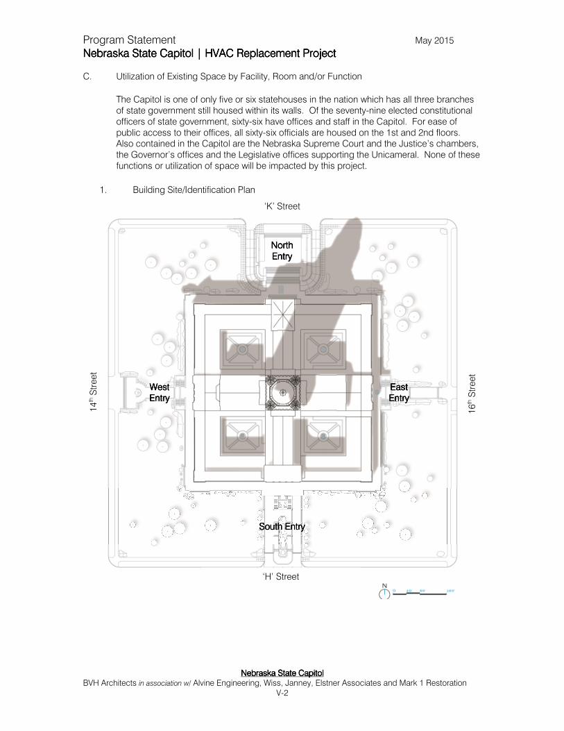
The Capitol is one of only five or six statehouses in the nation which has all three branches of state government still housed within its walls. Of the seventy-nine elected constitutional officers of state government, sixty-six have offices and staff in the Capitol. For ease of public access to their offices, all sixty-six officials are housed on the 1st and 2nd floors. Also contained in the Capitol are the Nebraska Supreme Court and the Justice’s chambers, the Governor’s offices and the Legislative offices supporting the Unicameral. None of these functions or utilization of space will be impacted by this project.
1. Building Site/Identification Plan
‘K’ Street
NorthNorthNorthNorth EntryEntryEntryEntry
16
th S
treet
14
th S
treet
‘H’ Street
South EntrySouth EntrySouth EntrySouth Entry
WestWestWestWest EntryEntryEntryEntry
EastEastEastEast EntryEntryEntryEntry
Program Statement May 2015
Nebraska State Capitol | HVAC Replacement ProjectNebraska State Capitol | HVAC Replacement ProjectNebraska State Capitol | HVAC Replacement ProjectNebraska State Capitol | HVAC Replacement Project
Nebraska State CapitolNebraska State CapitolNebraska State CapitolNebraska State Capitol BVH Architects in association w/ Alvine Engineering, Wiss, Janney, Elstner Associates and Mark 1 Restoration
V-3
2. Existing Floor Plans
See following pages for the Capitol Floor Plans

Program Statement May 2015
Nebraska State Capitol | HVAC Replacement ProjectNebraska State Capitol | HVAC Replacement ProjectNebraska State Capitol | HVAC Replacement ProjectNebraska State Capitol | HVAC Replacement Project
Nebraska State CapitolNebraska State CapitolNebraska State CapitolNebraska State Capitol BVH Architects in association w/ Alvine Engineering, Wiss, Janney, Elstner Associates and Mark 1 Restoration
V-4
D. Physical Deficiencies
1. HVAC Systems The existing mechanical HVAC systems serving the Nebraska State Capitol are a combination of several system types. The existing systems are mainly composed of induction unit, dual-duct, and constant volume systems installed during the 1964 HVAC renovation. A majority of the original 1920s heating and ventilating equipment was removed as a result of the renovation. The only original equipment that has remained in service is heating and ventilating air handling unit HV-1, approximately half of the original exhaust fans and many steam radiators. The 1964 renovation installed systems that focus on the use of air as the primary heat transfer medium while the original 1920s systems focused on the use of steam as the primary heat transfer medium. The 1964 air-based systems use large ductwork air distribution systems, which required the installation of numerous soffits, chases, and suspended ceilings in order to conceal the ductwork. However, the 1920s steam-based systems used piping distribution systems, which worked well with the many large volume spaces that have limited ceiling cavity space in the Capitol. The steam-based systems also used ductwork to distribute ventilation air. This ductwork was small in comparison to the 1964 renovation ductwork since it was not being used as the sole means to condition the Capitol.
Following the 1964 renovation were a series of smaller renovations at the Capitol. The significant HVAC renovations since 1964 include the 1980 cafeteria and kitchen renovation, the 1980 3rd floor and 2nd floor foyer renovation, the 1989 hearing and conference rooms renovation, the 1999 legislative technology center renovation, and the 2003 Secretary of State office renovation. Chilled water is currently supplied to the Capitol from the University of Nebraska-Lincoln’s central utility plant. Steam is currently supplied to the Capitol from the District Energy Corporation’s (DEC) steam plant that was specifically constructed in 1999 in order to serve the Capitol, Governor’s Residence, and the Nebraska State Office Building. The steam plant is located approximately one block north of the Capitol. Steam is converted to heating hot water within the Capitol for use in most of the HVAC systems. The induction unit system used throughout the Capitol consists of a two-pipe system, which means the system is either in heating or cooling mode and cannot provide both simultaneously. The entire Capitol is switched between the two modes twice a year resulting in thermal comfort complaints during this changeover in the spring and fall each year. Some specific HVAC deficiencies associated with the Capitol’s existing HVAC equipment includes the following:
• The changeover period (one week, twice a year) from heating to cooling and cooling to heating is very labor intensive.
• Warm weather during winter months cannot be addressed with cooling due to system changeover difficulties. The same is true for cold weather during summer months.
• There is poor thermal comfort control during mild weather days. • Moderate to poor thermal comfort control during peak summer cooling and
dehumidification design conditions.
Program Statement May 2015
Nebraska State Capitol | HVAC Replacement ProjectNebraska State Capitol | HVAC Replacement ProjectNebraska State Capitol | HVAC Replacement ProjectNebraska State Capitol | HVAC Replacement Project
Nebraska State CapitolNebraska State CapitolNebraska State CapitolNebraska State Capitol BVH Architects in association w/ Alvine Engineering, Wiss, Janney, Elstner Associates and Mark 1 Restoration
V-5
• The room-mounted induction units of the office spaces can only handle about 62°F chilled water because the units were not designed for any latent capacity and therefore have no condensate water removal system. The chilled water temperature must be constantly adjusted during the summer to keep the coil surface temperature just above the dew point temperature in order to prevent condensation from forming and flowing onto the adjacent floors. As a result, space temperature and humidity are both often higher than desired by the occupants.
• The room-mounted induction units of the office spaces are also inherently noisy resulting in a constant high frequency hissing noise which can be distracting to the occupants of these spaces.
• Many of the HVAC systems require frequent manual adjustments when the outdoor weather changes.
The 2007 HVAC Master Plan document identifies the many deficiencies of the HVAC and associate electrical systems serving the Nebraska State Capitol. Refer to the “Mechanical and Electrical Analysis” section of the 2007 HVAC Master Plan document for further systems details. The age of the majority of the Capitol’s HVAC systems is about 49 years old which is approximately double the median service life of this HVAC equipment. Some original heating and ventilating systems are still in operation today which makes them approximately 78 years old. As can be expected with aged equipment, the HVAC system operation is uneven, obsolete, maintenance intensive, and inefficient. The equipment is still in operation as a result of great preventative maintenance efforts by the OCC’s maintenance staff. Some fan and pump motors have been replaced. Many more equipment failures are imminent for years to come. Some cooling coils have already been replaced due to poor performance and leakage brought on by age. Improved occupant comfort, better indoor air quality and staff health, enhanced energy efficiency, and a more productive work environment are all strong reasons to implement an HVAC replacement. For these reasons, and many more contained in the full HVAC Master Plan, a majority of the existing HVAC equipment requires replacement or significant upgrading. Replacement of the HVAC system is a paramount priority for the stewardship of the Nebraska State Capitol.
The 1964 design and construction of the majority of the current HVAC systems compromised or hid from view many original architectural finishes. The historic fabric of the Capitol was damaged at many locations and the unique architectural finishes were obscured. One important goal of the 2007 HVAC Master Plan is to provide restoration of the lost, covered, or damaged architectural finishes. A more thoughtful and carefully designed HVAC system will allow this important historic preservation work to occur.
2. Electrical Systems and Emergency Generator
The Nebraska State Capitol’s electrical power distribution systems are not up to current modern office building standards, see “Appendix K: Previous Study – Substation Evaluation (2004)” located in the 2007 HVAC Master Plan document. Electrical Substations No. 1 and No. 2 serving the Capitol are in need of replacement. This work is a precursor to the HVAC project as the new HVAC system requires this electrical work to be completed first. Some specific deficiencies associated with the Capitol’s existing electrical power distribution system include the following:
Program Statement May 2015
Nebraska State Capitol | HVAC Replacement ProjectNebraska State Capitol | HVAC Replacement ProjectNebraska State Capitol | HVAC Replacement ProjectNebraska State Capitol | HVAC Replacement Project
Nebraska State CapitolNebraska State CapitolNebraska State CapitolNebraska State Capitol BVH Architects in association w/ Alvine Engineering, Wiss, Janney, Elstner Associates and Mark 1 Restoration
V-6
• Of the three existing electrical substations, Substations No. 1 and No. 2 are the weakest link in the State Capitol electrical distribution system.
• Switchboards installed in Substations No. 1 and No. 2 date back to the late 1950s. These are the only major portions of the State Capitol electrical distribution system that have not been modernized.
• Difficulties have been encountered regarding ongoing maintenance of Substations No. 1 and No. 2.
• The internal components within Substations No. 1 and No. 2 have served well beyond their anticipated useful life.
• Replacement components for Substations No. 1 and No. 2 are no longer available from traditional sources. The secondary market has limited access to replacement parts. If available, these parts are costly and have long lead time for delivery.
3. Life Safety Systems – Fire Alarm/ Sprinkler/ Generator
a. Fire Alarm Systems
The Nebraska State Capitol is a high-rise building by simple observation and by building code definition. For many years, the stewards of the Capitol have been working to bring this very public high-rise office building into compliance with fire protection and life safety codes. The 1st, 2nd, and 3rd floors have partial fire alarm systems installed which is a significant deficiency. Additionally, major deficiencies exist regarding missing or insufficient fire alarm speakers and strobes. See “Appendix J: Previous Study – Fire Protection Evaluation (2005)” located in the 2007 HVAC Master Plan document for a more detailed description of fire alarm systems in the Capitol.
b. Fire Sprinkler Systems A review was performed of the general existing conditions for the fire sprinkler and standpipe system on the 1st, 2nd, and 3rd floors. The following observations were made:
• The 1st, 2nd, and 3rd floors are not sprinkled.
• The hose cabinets and risers are served from the 6-inch basement fire pump loop.
• A new fire pump was installed in the basement in 1999. It is rated to deliver 500 gpm against 175 psi boost pressure.
• A new 6-inch fire main was installed in 2004 to serve only the fire system in the Capitol.
• The basement is sprinkled. • Office floors, 4 and up of the tower were sprinkled in 2000-2001.
• The basement sprinkler system was connected to the fire pump in 2004 with pressure reducing valves installed.
• Tower elevator shafts were sprinkled at two floor intervals by completion of the Tower Elevator Modernization project in 2014.
See “Appendix J: Previous Study – Fire Protection Evaluation (2005)” located in the 2007 HVAC Master Plan document for a more detailed description of fire sprinklers

Program Statement May 2015
Nebraska State Capitol | HVAC Replacement ProjectNebraska State Capitol | HVAC Replacement ProjectNebraska State Capitol | HVAC Replacement ProjectNebraska State Capitol | HVAC Replacement Project
Nebraska State CapitolNebraska State CapitolNebraska State CapitolNebraska State Capitol BVH Architects in association w/ Alvine Engineering, Wiss, Janney, Elstner Associates and Mark 1 Restoration
V-7
in the Capitol. The remainder of the Capitol building needs to be protected by fire sprinklers, except for Preservation Spaces.
c. Emergency Generator
The entire Capitol is provided with a form of emergency power by means of redundant primary electrical services. The normal power primary electrical service is provided from Lincoln Electric System (LES) while the emergency power primary electrical service is provided from the University of Nebraska at Lincoln (UNL). The underground power primary feeder from UNL has been identified as being at risk for failure. The feeder is in the range of 70+ years old and has served well beyond its anticipated useful life. The Nebraska State Fire Marshal’s Office reviewed the existing emergency power arrangement in 2010 and required that an emergency generator must be installed to provide true emergency power for at least the life safety systems within the Capitol. A generator study was completed in 2013 which evaluates and recommends generator options for the Capitol based on generator size, quantity, and location. Copies of the Nebraska State Capitol Generator Study are available for review from the Office of the Capitol Commission.
4. Roof – Insulation and Energy Conservation Improvements from Recent Projects The roofing at the Nebraska State Capitol was the subject of an intensive replacement and upgrade circa 2007-2010 (Figure A at the end of this section). At that time the copper roofing of the lower slope roofs were removed and replaced with in-kind copper panels. In addition the number of interior drains was increased dramatically and drainage slope was improved around all of the drains. While not a physical deficiency it should be noted that these improvements have had a positive impact upon energy conservation. The new roofing included the addition of 1-1/2 inch thick rigid polyisocyanurate panels placed against the original poured gypsum concrete substrate and marine-grade plywood placed over the insulation that was toggle bolted through the insulation and gypsum substrate. A W.R. Grace Ultra “peel and stick” sheet waterproof membrane was installed atop the plywood. At batten seam areas the copper sheet was separated from the Grace Ultra by rosin paper. At flat lock areas the copper sheet was separated from the Grace Ultra by two layers of 15 pound felt paper and rosin paper. The quarry-tiled flat roofs above the four 5th floor clerestories and at the 14th level observation deck were also replaced. The replacement was a pedestal system composed of pavers of quarry set into fiber reinforced concrete panels (Figure B). No additional insulation was installed during this work.
5. Exterior Walls
The Nebraska State Capitol has monolithic brick and limestone masonry walls that are locked into a steel frame that is encased in concrete as a fireproofing measure. The exterior walls were the subject of an intensive restoration project that was begun circa 1996 and completed in 2011 (Figure C). The exterior masonry walls presently are in good condition.
Program Statement May 2015
Nebraska State Capitol | HVAC Replacement ProjectNebraska State Capitol | HVAC Replacement ProjectNebraska State Capitol | HVAC Replacement ProjectNebraska State Capitol | HVAC Replacement Project
Nebraska State CapitolNebraska State CapitolNebraska State CapitolNebraska State Capitol BVH Architects in association w/ Alvine Engineering, Wiss, Janney, Elstner Associates and Mark 1 Restoration
V-8
6. Windows at the Base of the Capitol
The exterior windows at the building base, the 1st through the 3rd floors of the Capitol, are original to the building and considered historic fabric. Most of these windows are operable for natural ventilation as this was the original means of cooling the Capitol during the warmer months of the year. These windows allow some leakage of outdoor air to the interior of the building, known as infiltration. These base windows of the Nebraska State Capitol consist of steel frames and operable casement sash set into the masonry openings within the façade (Figure D). A steel sub-frame is set within the wall construction that accepts the frame and sash. Interior finishes, such as plaster at the jambs and head and slate stools at the sill, typically abutt the sub-frame (Figure E). The windows are typically glazed with 1/8 inch thick glass units that are separated by horizontal and vertical muntins. Steel glazing stops are screwed to the sash on the interior with a flush glazing compound on the exterior. Weep holes are located in the sill of the frame to allow incidental water collected at the sill to drain to the exterior (Figure F). There is no weather-stripping on either the sash or the frame. The operable sash typically has a vertical bar locking mechanism that is operated with a central knob. Keeper arms are located at the sill of the window and can be adjusted with a sliding thumb screw mechanism to keep the window open at various widths (Figure G). Approximately 30% of the roughly 1,000 windows in the Capitol, which represents approximately 40% of the glazing in area, underwent a restoration and reparation project in 1980’s. Windows that were not repaired have excessive infiltration which impacts the HVAC system and ultimately causes humidity and temperature discomfort within the building. The 1980s repairs typically consisted of the following:
• Removal, stripping and painting of sash and frames
• Installation of new glass, including insulating glass (IG) units in some areas
• Stripping and painting of sub-frames in situ
• Installation of weather-stripping on casement sash
The exterior finish on the windows is currently in good condition with evidence of chalking on the sash and frame (Figure H). Failed IG units are located throughout the areas where they were installed (Figure J). Previously installed weather-stripping has been removed or is missing from nearly all repaired windows. Due to the lack of weather-stripping the windows are very susceptible to air infiltration and exfiltration. They depend on metal-to-metal contact from the sash to the frame to resist air movement. Increased air leakage can result in higher heating and cooling loads and ultimately higher energy costs.
7. Tower Window Spandrels The bronze tower windows contain spandrels fitted with opaque black glass glazing, that cover the floor structure at each tower floor level, from the seventh through the twelfth floors. Through recent water testing, it was found that sealant details in these tower window spandrels are the source of chronic water leakage on the tower floors.

Program Statement May 2015
Nebraska State Capitol | HVAC Replacement ProjectNebraska State Capitol | HVAC Replacement ProjectNebraska State Capitol | HVAC Replacement ProjectNebraska State Capitol | HVAC Replacement Project
Nebraska State CapitolNebraska State CapitolNebraska State CapitolNebraska State Capitol BVH Architects in association w/ Alvine Engineering, Wiss, Janney, Elstner Associates and Mark 1 Restoration
V-9
This leakage is causing severe interior plaster and paint damage found typically at window heads and adjacent jambs. This water leakage also greatly impacts the HVAC systems and contributes to office space humidity and temperature issues primarily during the summer months (Figure L).
8. Interior Finishes and Historic Fabric
The interior finish systems throughout the Capitol are typically in fair to good condition. Many elements of the interior finishes in the building have been restored or conserved by the OCC. The following discussion is focused on those areas that will be impacted by the HVAC project. Corridors At several locations, suspended ceilings have been added to conceal the 1964 HVAC renovations (Figure K). The floors in the corridors are decorative patterned stone. The walls are limestone and plaster. Approximately 30 percent of the paint on the corridor walls has been stripped at the 1st floor and approximately 20 percent of the paint on the walls has been stripped at the 2nd floor. At other locations, the coatings have cracked from the build-up of coating layers and are in poor condition. Some paint analysis has been conducted in addition to samples of plaster removed prior to paint removal. The analysis denotes the presence of lead based paint. The 1st floor ceilings are either smooth painted plaster (2nd floor coffered plaster) or Guastavino tile. The plaster ceilings are in good to fair condition and the Guastavino tile is in good condition. Typical offices at 1st and 2nd Floors The walls and ceilings consist of painted plaster. As part of on-going renovations, paint is removed from the walls and ceilings and the surfaces restored (Figure M). Historic finish analysis has been conducted at some locations by others. At other locations, samples of plaster were retained as archival samples by Capitol staff. At select locations, acoustic tile suspended ceilings have been added to conceal previous HVAC renovations. In the offices, the floors historically were covered with green battleship linoleum which have either been largely replaced or covered with carpeting. Painted wood picture molding is present in many offices. Some rooms have original soffits or enlarged soffits (Figure N). Painted surfaces that contain original paint typically contain lead base paint (LBP). The OCC staff, during any restoration work taking place where LBP is present, is diligent in its proper abatement for future safety of the Capitol occupants.
Capitol Interior Preservation Zone 1 Spaces The following spaces have been designated as “Preservation Spaces” in the Nebraska State Capitol by the Office of the Capitol Commission. (Also see discussion in Chapter 8 regarding Preservation Spaces) This designation recognizes the fact that these areas have the highest quality of materials and finishes. Walls, floors, and ceilings in these spaces are typically clad with marble, Guastavino tiles, ornate inlaid or stenciled woodwork, custom artwork, or painted murals.

Program Statement May 2015
Nebraska State Capitol | HVAC Replacement ProjectNebraska State Capitol | HVAC Replacement ProjectNebraska State Capitol | HVAC Replacement ProjectNebraska State Capitol | HVAC Replacement Project
Nebraska State CapitolNebraska State CapitolNebraska State CapitolNebraska State Capitol BVH Architects in association w/ Alvine Engineering, Wiss, Janney, Elstner Associates and Mark 1 Restoration
V-10
The following areas of the building are considered to be Preservation Spaces:
• Vestibule • Foyer • Rotunda
• East Chamber • East Lounge
• West Chamber • West Lounge
• Supreme Court and Judges’ Consultation Room • Court of Appeals and Judges’ Consultation Room • Lawyer’s Room
• Chief Justice’s Suite (Private Office and Library) • Governor’s Suite (Governor’s Private Office, Chief of Staff’s Office, Governor’s
Reception Room, and Governor’s Hearing Room)
• Law Library and Reading Room • Memorial Chamber (Fourteenth floor)
• Public Corridors on 1st, 2nd, and 3rd floors • Tower Elevator Vestibules and SE Stairway • Restrooms, 1st floor and above
The remaining spaces in the Capitol are designated Adaptive Use Spaces and either administrative office spaces or utilitarian support spaces. (Please see the attached floor plans which delineate the various Preservation Zones and Spaces within the Capitol). Preservation Zone spaces impacted by the HVAC project that have unique and decorative finishes include murals on plaster and canvas (Law Library), mosaics (Memorial Chamber), fabric coverings (Governor’s Suite), wavy decorative plaster (Law Library Reading Room), and wood (Legislative Chambers). The decorative surfaces have been conserved at various times. Specific deleterious conditions were observed:
• Peeling paint at ceiling such as Governor’s Hearing Room. Paint currently failed at isolated locations, expected temperature and humidity cycling during project will likely cause additional failures
• Walls of the Governor’s Hearing Room have been coated reportedly with a cementitious coating (Figure P)
• Failed wavy plaster in west side 2nd floor
• Water damage to ceiling in Governor’s Suite
Program Statement May 2015
Nebraska State Capitol | HVAC Replacement ProjectNebraska State Capitol | HVAC Replacement ProjectNebraska State Capitol | HVAC Replacement ProjectNebraska State Capitol | HVAC Replacement Project
Nebraska State CapitolNebraska State CapitolNebraska State CapitolNebraska State Capitol BVH Architects in association w/ Alvine Engineering, Wiss, Janney, Elstner Associates and Mark 1 Restoration
V-11
9. Structural
The Nebraska State Capitol has a masonry bearing wall quadrangular base with limited steel columns and steel floor framing supporting a reinforced poured concrete pan joist floor system. The tower is a steel frame system supporting a reinforced poured concrete floor system with concrete around all steel structural members for fire-proofing throughout the entire building. Guastavino tile vaulting and domes are present for both structural and ornamental purposes at three of the four ground floor entrances, the first and second floor rotunda areas, the Governor’s Private Office and Reception Room and the East Chamber and Lounge. There is some redundancy of concrete piers below the west wing due to a change in the design during construction which increased the size of the West Chamber. The floor systems are generally poured reinforced concrete pan joists with vertical legs at 20 inches on center. Integral to these poured slabs are steel beams at interior column lines at about 26 foot on center, although in limited floor areas (and at many roof slabs) flat reinforced slabs are poured with the structural steel beams at roughly 7 foot on center. The floor beams are encased in concrete (Figure Q). Poured reinforced structural floor slabs spanning between the steel beams or in pan joists are typically 4 inches in thickness. The finished floor above the structural slab has a typical 5 inch thickness composed of a 3 inch cinder fill covering conduit with a 2 inch concrete finished slab. The structural floor system is typically in good condition. As part of the HVAC project, any proposed penetrations through the structural floor should not cut into the steel beams or affect their bearing locations. Concrete slab penetrations may require reinforcing of the concrete around those penetrations. The topping slab above the structural slab can be removed; however, mapping and considerable care must be taken to avoid damage to existing rigid floor conduit systems. If penetrations are required through any of the arch systems the penetrations will need to be reinforced with a flush concrete ring at the perimeter of that penetration. Considerable care must be taken to avoid cutting channels or vertical risers through masonry walls where existing ductwork cannot accommodate such risers.
E. Programmatic Deficiencies
The HVAC Replacement Project is focused primarily upon the installation of new systems and the repairs to the spaces and finishes impacted by this installation. No new space will be created or no wholesale reorganization and remodeling of space within the Capitol is planned except for two small areas on the 3rd floor and in the basement. All other spaces will remain essentially as is.
The southwest Law Library stack and rare book storage rooms (Rooms 335 and 335B) are the spaces in which volumes of rare Nebraska Law Library books are stored. The spaces are constructed of un-insulated painted masonry walls, painted gypsum ceiling and concrete floors. The space has no air conditioning and is only heated by fin tube radiators. As a result there are large temperature and humidity swings throughout the year which is causing great damage to the important and fragile contents. As a new HVAC system is installed in these areas, it is proposed that these spaces be rehabilitated to allow for a temperature and humidity controlled environment for archival storage.

Program Statement May 2015
Nebraska State Capitol | HVAC Replacement ProjectNebraska State Capitol | HVAC Replacement ProjectNebraska State Capitol | HVAC Replacement ProjectNebraska State Capitol | HVAC Replacement Project
Nebraska State CapitolNebraska State CapitolNebraska State CapitolNebraska State Capitol BVH Architects in association w/ Alvine Engineering, Wiss, Janney, Elstner Associates and Mark 1 Restoration
V-12
The east end of the dock in the basement level (Room 18B) is very small and does not allow the proper delivery and staging of material shipped in and out of the Capitol via this dock. The acute shortage of space will be even more exacerbated as the HVAC project is implemented due to the high volume of items that will be delivered and transported to the basement mechanical rooms. This has caused the need for the dock to be enlarged by extending the size of the area eastwards into the basement. Space will be borrowed from an existing shop area to accommodate a larger dock and will allow better utilization of space for the needs of the Capitol.
F. Replacement Cost of the Existing Building
The OCC has developed the replacement cost of the Capitol for purposes of state insurance. A conservative replacement value of $476,426,400 was estimated by the consultant team based upon recent monumental construction projects in the region.

Program Statement May 2015
Nebraska State Capitol | HVAC Replacement ProjectNebraska State Capitol | HVAC Replacement ProjectNebraska State Capitol | HVAC Replacement ProjectNebraska State Capitol | HVAC Replacement Project
Nebraska State CapitolNebraska State CapitolNebraska State CapitolNebraska State Capitol BVH Architects in association w/ Alvine Engineering, Wiss, Janney, Elstner Associates and Mark 1 Restoration
VI-1
VI.VI.VI.VI. Facility Requirements and the Impact of the Proposed ProjectFacility Requirements and the Impact of the Proposed ProjectFacility Requirements and the Impact of the Proposed ProjectFacility Requirements and the Impact of the Proposed Project A. Functions/Purpose of the Proposed Program
1. Activity Identification and Analysis
Not applicable 2. Projected Occupancy/Use Levels
a. Personnel Projections
The total Capitol occupancy approaches 1,000 persons when the Legislature is in session and on average 850 persons when not in session. This occupancy range will be maintained once the HVAC project is completed.
b. Description and Justification of Projected Public Occupancy
The public occupancies projected and to be used for sizing the HVAC system and also to be utilized for life safety improvements are as follows:
FFlloooorr//LLeevveell OOccccuuppaannccyy
First FloorFirst FloorFirst FloorFirst Floor
Northwest Hearing Room 1524 135 people
Southwest Hearing Room 1525 135 people
Northeast Hearing Room 1510 125 people
Southeast Hearing Room 1507 125 people
Hearing Room 1003 40 people
Hearing Room 1113 140 people
Conference Room 1126 50 people
Conference Room 1200 50 people
Conference Room 1224 20 people
Cafeteria 110 people
Second FloorSecond FloorSecond FloorSecond Floor
West Chamber 300 people
West Lounge 79 people
East Chamber 300 people
East Lounge 79 people
Supreme Court 50 people
Court of Appeals 72 people
Foyer 150 people
Third FloorThird FloorThird FloorThird Floor
Law Library 100 people
Fourth FloorFourth FloorFourth FloorFourth Floor 10 people
Fifth FloorFifth FloorFifth FloorFifth Floor 25 people
Sixth FloorSixth FloorSixth FloorSixth Floor 15 people
Seventh through Twelfth FloorsSeventh through Twelfth FloorsSeventh through Twelfth FloorsSeventh through Twelfth Floors 15 people per floor
Thirteenth FloorThirteenth FloorThirteenth FloorThirteenth Floor 12 people
Fourteenth Floor (Memorial Chamber)Fourteenth Floor (Memorial Chamber)Fourteenth Floor (Memorial Chamber)Fourteenth Floor (Memorial Chamber) 25 people
Program Statement May 2015
Nebraska State Capitol | HVAC Replacement ProjectNebraska State Capitol | HVAC Replacement ProjectNebraska State Capitol | HVAC Replacement ProjectNebraska State Capitol | HVAC Replacement Project
Nebraska State CapitolNebraska State CapitolNebraska State CapitolNebraska State Capitol BVH Architects in association w/ Alvine Engineering, Wiss, Janney, Elstner Associates and Mark 1 Restoration
VI-2
Please note that the 2nd floor West Chamber and associated West Lounge are normally not occupied during the summer months; however, the cooling capacity of the new system shall be sized based on the maximum occupancy occurring during the design temperatures for Lincoln, Nebraska as stated by the 2004 ASHRAE Handbook of Fundamentals. Per the OCC the maximum occupancy of the west chamber may occur if a special legislative session is required during the summer.
Also, the 2nd floor East Chamber and the associated East Lounge are occupied less during the summer months; however, the cooling capacity of the new system shall be sized based on the maximum occupancy occurring during the design temperatures for Lincoln, Nebraska as stated by the 2004 ASHRAE Handbook of Fundamentals. According to the OCC, the maximum occupancy of the east chamber may occur if a special event is held during the summer.
B. Space Requirements
1. Square Footage by Individual Areas and/or Functions
As previously discussed, no new square footage will be added to the Capitol and the existing functions will remain in their original locations.
2. Basis for Square Footage/Planning Parameters
Not Applicable 3. Square Footage Difference between Existing and Proposed Areas (net and gross)
There will be very minor impacts on existing spaces and their square footage due to the removal of existing HVAC equipment.
• Approximately 60% of the existing floor area covered by the existing continuous HVAC induction unit cabinets will be reclaimed in the building base general office spaces by removing the induction units and replacing them with smaller modular fan coil units.
• Approximately 55% of the existing floor area covered by the existing continuous HVAC induction unit cabinets will be reclaimed in the tower general office spaces by removing the induction units and replacing them with smaller modular fan coil units.
• Approximately 90% of the existing floor area will be reclaimed in the northeast and the southwest tower elevator vestibules by reducing the size of the existing HVAC ductwork and piping chases added there as part of the 1964 HVAC renovation project.
C. Impact of the Proposed Project on Existing Space
1. Reutilization and Functions
The impact of the project on the existing spaces and occupants of the Capitol will be very positive. The project will allow for the reclamation of large volumes of architectural space finishes, and details, which were lost of concealed during the 1964 HVAC renovation project, while also improving the thermal comfort and acoustical airborne noise levels for the occupants of the Capitol.

Program Statement May 2015
Nebraska State Capitol | HVAC Replacement ProjectNebraska State Capitol | HVAC Replacement ProjectNebraska State Capitol | HVAC Replacement ProjectNebraska State Capitol | HVAC Replacement Project
Nebraska State CapitolNebraska State CapitolNebraska State CapitolNebraska State Capitol BVH Architects in association w/ Alvine Engineering, Wiss, Janney, Elstner Associates and Mark 1 Restoration
VI-3
2. Demolition
Demolition work as part of this project will be extensive and will be disruptive. The work will include:
• Demolition of the existing wall mounted HVAC induction units in the general office spaces will occur throughout the Capitol.
• Demolition and reduction in size of the existing HVAC ductwork and piping chases in the tower elevator vestibule spaces will occur.
• Demolition of the existing first floor corridor acoustical tile lay-in ceilings will occur. These ceilings were added below the original plaster ceilings as part of the 1964 HVAC Renovation project to conceal ductwork that was added as part of that project.
• Demolition of all of the existing HVAC air handling units and associated systems and most of the exhaust fans as described in the “Recommended HVAC Systems” section of the 2007 HVAC Master Plan document.
• Demolition of electrical Substations No. 1 and No. 2 per the “Appendix K: Previous Study – Substation Evaluation (2004)” which is reprinted as an appendix to the 2007 HVAC Master Plan document.
• Removal of window sashes in order to perform selected repairs and re-glazing will occur to many openings around the base of the building.
• Selective demolition will be required to allow for sprinkler piping and fire detection system conduits to be installed.
• As a result of the above work and the repairs required, the majority of carpet and selected paint finishes in office areas will require removal and repair.
3. Renovation/Restoration
The renovation and restoration resulting from the installation of the new HVAC systems will also be very extensive. As noted previously very little of the project is devoted to construction of new space but rather the majority is the repair and restoration of finishes and systems as a result of the installation of HVAC and fire/life safety improvements. As noted more extensively in Chapter VIII the work will entail:
• Renovation of the mechanical, electrical, and architectural systems as described in Chapter VIII.
• Renovation/replacement of electrical Substations No. 1 and No. 2. • Installation of the recommended basement, first, second, and third floor fire
protection systems.
• Completion of the first, second and third floor fire alarm systems per recommendations in Chapter VIII.
• Installation of an emergency generator per the Nebraska State Capitol Generator Study.
• Renovation of selected building base and tower general office space walls, ceilings, and floors as recommended.
• Completion of the renovation of the existing building base exterior windows. • Renovation of the existing tower window spandrels.

Program Statement May 2015
Nebraska State Nebraska State Nebraska State Nebraska State Capitol | HVAC Replacement ProjectCapitol | HVAC Replacement ProjectCapitol | HVAC Replacement ProjectCapitol | HVAC Replacement Project
Nebraska State CapitolNebraska State CapitolNebraska State CapitolNebraska State Capitol BVH Architects in association w/ Alvine Engineering, Wiss, Janney, Elstner Associates and Mark 1 Restoration
VII-1
VII.VII.VII.VII. Analysis of Equipment RequirementsAnalysis of Equipment RequirementsAnalysis of Equipment RequirementsAnalysis of Equipment Requirements
A. List of Available Equipment for Re-use
It is the intent to reuse where deemed appropriate, original HVAC equipment that will not compromise the quality or durability of the final design. One type of original equipment identified during the programming phase that can be reused includes the existing exhaust fans. These well-built and sturdy exhaust fans may be reused as-is, with a checkout of bearings and lubrication or they may be repurposed with a new high-efficiency motor. If found to be of appropriate size, location, and routing much of the existing heavy gauge ductwork will be reused whenever possible in order to reduce costs and preserve historic mechanical system elements of the Capitol. Although many of the existing steam radiators do not currently function, it is anticipated that the existing historic radiators will all be retained due to their aesthetic connection to the original construction. In some cases, the historic steam radiators will be retrofitted to use heating hot water with modern valves, controls and heating water piping. These refitted radiators will be reused for the purpose of heating the area in which they were originally installed. All piping and conduit will not be reused unless replacing it in a similar location will cause destruction of historic fabric that might be preserved if the piping was reused. This will be done on a case by case basis for decision once design is initiated. Also, heating and ventilating unit HV-1 is intended to be reused. The air handling equipment will be serviced and updated as deemed appropriate for initiating the new HVAC system with a long service life. Generally speaking, if original HVAC equipment is not to be reused and the space allows for it to be left in place, such equipment will be left in place for historic preservation purposes. During the design and construction process, it may be decided to relocate some removed equipment to a new location within the mechanical spaces of the building to allow for its storage and preservation. Otherwise, such historic equipment that is deemed to not be reused in the existing system and has no place to be archived within the building will be disposed of in a manner as approved by the OCC.
B. Additional Equipment
1. Fixed Equipment
The budget for any fixed equipment for the project is included in the Total Project Cost as shown in Section IX-Project Budget and Fiscal Impact. Fixed equipment includes Emergency Generator and associated costs. No other equipment such as usually needed in building projects including case work, projection screens, etc. is envisioned for this project.
2. Movable Equipment
No movable equipment is envisioned for this project and is not included in the project budget.
Program Statement May 2015
Nebraska State Nebraska State Nebraska State Nebraska State Capitol | HVAC Replacement ProjectCapitol | HVAC Replacement ProjectCapitol | HVAC Replacement ProjectCapitol | HVAC Replacement Project
Nebraska State CapitolNebraska State CapitolNebraska State CapitolNebraska State Capitol BVH Architects in association w/ Alvine Engineering, Wiss, Janney, Elstner Associates and Mark 1 Restoration
VII-2
3. Special or Technical Equipment
No special or technical equipment beyond that needed for the HVAC systems and controls or fire detection systems are envisioned for this project and is not included in the project budget.
Program Statement May 2015
Nebraska State Capitol | HVAC Replacement ProjectNebraska State Capitol | HVAC Replacement ProjectNebraska State Capitol | HVAC Replacement ProjectNebraska State Capitol | HVAC Replacement Project
Nebraska State CapitolNebraska State CapitolNebraska State CapitolNebraska State Capitol BVH Architects in association w/ Alvine Engineering, Wiss, Janney, Elstner Associates and Mark 1 Restoration
VIII-1
VIII.VIII.VIII.VIII. Design Considerations and Recommendations Design Considerations and Recommendations Design Considerations and Recommendations Design Considerations and Recommendations
A. Historic and Architectural Significance
The significance of the Nebraska State Capitol and its landscape are recognized by the building and landscape’s designation as a National Historic Landmark. As such, any project implemented must be developed in strict adherence to The Secretary of the Interior’s
Standards for the Treatment of Historic Properties.
B. Special Protection/Preservation/Construction Considerations
The Office of the Capitol Commission (OCC) has developed standard specifications and standards for work that is carried out in the building. Recently these were compiled into The
Nebraska State Capitol Interior Restoration Master Specifications and Details, dated March 22, 2010. These shall be referred to and adhered to as design progresses and the HVAC construction is implemented.
C. HVAC System Replacement
As stated in the “Mechanical and Electrical Analysis” section of the 2007 HVAC Master Plan, all existing AHUs and supporting equipment in the Capitol require removal and replacement with new AHU systems and equipment due to the deficiencies presented there. The deficiencies include but are not limited to the existing equipment operating at or beyond the industry standards for recommended useful service life, insufficient capacity, and serious maintenance problems. As a result, all of the existing AHUs are to be replaced with the exception of HV-1. AHU HV-1 is original from the 1920s and shall be retrofitted to continue service into the future. Over half of the spaces within the Capitol are considered to be general office spaces while the remaining spaces are typically either preservation spaces or adaptive use spaces. The spaces other than the general office spaces in the Capitol shall typically be served by single-duct VAV systems as indicated in the “Recommended HVAC Systems” section of the 2007 HVAC Master Plan.
The 2007 Nebraska State Capitol HVAC Master Plan contained a comparison of two HVAC options. The first option was a 4-pipe fan coil system served by UNL chilled water and the District Energy Corporation’s steam. The second option was air handling units with VAV, air boxes with terminal reheat serving all spaces. As shown in the 2007 Master Plan, these two options were in competition to serve over half of the building’s spaces, comprised mostly of office suites in the base and tower. Both options had common HVAC elements, which included air handling units to serve large gathering spaces such as legislative chambers, meeting rooms, courtrooms, etc. Common mechanical elements include systems, equipment, and installation practices which are required for many locations but are listed once here for simplicity.
1. Original equipment and ductwork from the 1920s design shall be reused as much as
possible. Where 1920s equipment or ductwork cannot be reused, it shall be abandoned in place or relocated to an approved area as directed by the OCC.

Program Statement May 2015
Nebraska State Capitol | HVAC Replacement ProjectNebraska State Capitol | HVAC Replacement ProjectNebraska State Capitol | HVAC Replacement ProjectNebraska State Capitol | HVAC Replacement Project
Nebraska State CapitolNebraska State CapitolNebraska State CapitolNebraska State Capitol BVH Architects in association w/ Alvine Engineering, Wiss, Janney, Elstner Associates and Mark 1 Restoration
VIII-2
2. Any mechanical work that is not original to the 1920s design may be removed. The OCC shall be the judge of original vs. non-original material and has final rights of salvage.
3. Ductwork material/construction and insulation: Galvanized sheet metal shall be used throughout unless anticipated moisture dictates copper material is more appropriate. Gauge of metal, fabrication, and installation shall be per Code and current sheet metal SMACNA Standards. The OCC prefers the sheet metal gauge to match that of the existing 1920s sheet metal. Generally, 1½-inch fiberglass blanket insulation (1.5 lb./cu.ft. density) with FSK foil jacket shall be used on the exterior of all concealed ductwork. Double wall ductwork shall be used where ductwork must be routed exposed or where sensitive acoustic concerns exist. Radius fittings shall always be installed where possible.
4. The spaces other than general office spaces in the Capitol are typically “Class B”
environments that are designated as preservation spaces. These typically large spaces shall utilize single duct VAV systems with zone heating to allow for adequate air change rates, pressurization, and enhanced dehumidification. All VAV terminal units shall have a minimum supply air setting which shall be dictated by the greater of either minimum space ventilation requirements or building pressurization requirements.
5. Ventilation Control: A demand limiting basis of ventilation control shall be utilized.
Sources of outdoor air, such as DOAUs, shall have their speed controlled with the use of a variable frequency drive (VFD) through the monitoring of carbon dioxide levels in served spaces to allow for compliance with ASHRAE Standard 62.1. For other types of ventilation equipment, carbon dioxide monitoring shall turn off/on or open/close dampers as appropriate to satisfy required carbon dioxide levels. The demand limiting control strategy must take into account building pressurization. Static pressure sensors across key building areas such as the loading dock and the tops of stair towers, shall override outdoor air limiting controls to satisfy appropriate pressurization set points and reduce the buildings inherent “stack effect.”
6. All free cooling control shall be enthalpy based to recognize humid outdoor conditions. 7. When the Capitol is not occupied, a nighttime room temperature reset schedule shall
be used, similar to the existing schedule. However, an occupant controlled temperature override shall be provided with a thermostat in each room to allow for simplified environmental control when working during unoccupied hours.
8. It is recommended that steam in the new HVAC system only be used in steam-to-hot water convertors. It is also required that steam not be used directly in heating coils or directly in humidification. All steam heating coils will be demolished. New hot water coils in AHUs, shall be utilized as stated below in the individual area recommendations contained in this report. Steam will be used directly in the three major steam convertors for the generation of heating hot water. Steam will continue to be used in the generation of domestic hot water. Domestic hot water systems are not part of this HVAC Master Plan.
9. Original 1920s steam radiators, which are visible to the public and are still in operation,
shall be converted to use hot water where possible. Typical spaces included are stairways, vestibules, and corridors. The 2nd floor Rotunda and Foyer, and the 4th, 5th, 14th, 15th floors, and access stair tank room radiators will be converted to hot water.

Program Statement May 2015
Nebraska State Capitol | HVAC Replacement ProjectNebraska State Capitol | HVAC Replacement ProjectNebraska State Capitol | HVAC Replacement ProjectNebraska State Capitol | HVAC Replacement Project
Nebraska State CapitolNebraska State CapitolNebraska State CapitolNebraska State Capitol BVH Architects in association w/ Alvine Engineering, Wiss, Janney, Elstner Associates and Mark 1 Restoration
VIII-3
Areas that have visible radiators, but are to be heated and cooled, shall have the radiators abandoned in place. If the radiator is in the way of new construction, it can be removed and salvaged upon request as directed by the OCC.
10. Piping material and insulation: Type K copper piping shall be used for chilled water,
heating hot water, and condensate drainage to provide extended service life. Type K copper piping has a thicker pipe wall than Type L copper piping so Type K will provide a longer pipe wall life. Piping shall use closed cell type insulation with self-seal option for joints. UV resistant PVC jackets shall be provided to protect the insulation and to ensure condensate prevention for concealed piping. One inch thickness shall be used for concealed applications. For exposed piping, ½ inch thickness shall be used. The ½ inch thickness provides roughly 80% of the thermal valve while it gives the space benefit for compact installation in smaller core-drilled holes and tight shafts or soffits and the aesthetic advantage of being less noticeable as non-original to the Capitol. The PVC jacket shall be color matched or painted to blend in with the adjacent surfaces. All insulation and PVC jackets must meet flame-spread indexes and smoke-developed indexes as required by the NFPA.
11. Prior to the commencement of any work associated with this Master Plan, the asbestos report located in Appendix I must be consulted.
12. All ductwork that serves more than one floor shall be provided with combination fire and
smoke dampers at each floor’s shaft wall penetration.
13. Tower areas that have existing fire sprinklers shall be modified as required to ensure complete sprinkler coverage with the added piping, conduits, and equipment of the new HVAC system.
14. All piping penetrations shall be fire stopped with fire-rated caulk to match the fire rating
of the respective wall or floor. 15. All mechanical rooms shall have floor drains for condensate removal. If a mechanical
room does not currently have a floor drain then one shall be provided with sanitary waste piping connecting to the nearest sanitary waste piping main.
At the time of the 2007 HVAC Master Plan, the “General Office Space – Alternative 1: Fan Coil Unit System” was recommended to be installed in the Capitol instead of the “General Office Space - Alternative 2: Single Duct VAV with Zone Heating System” due to the following reasons.
• Ability to maintain and improve architectural aesthetics to near “original” 1920s Condition
• Pipe-based system and conditioned outdoor-air ductwork allows for recovery of most ceiling space in the 1st floor corridors
• Conditioned outdoor-air ductwork is much smaller than the supply-air ductwork required for a VAV system, thus allowing for smaller penetrations
• Allows for fast and flexible project phasing • Perimeter fan-coil units honor the original design intent of providing space
conditioning at windows as was previously provided by the radiators
• Fan-coil units can be mounted under perimeter windows, which helps control cold drafts in the winter
Program Statement May 2015
Nebraska State Capitol | HVAC Replacement ProjectNebraska State Capitol | HVAC Replacement ProjectNebraska State Capitol | HVAC Replacement ProjectNebraska State Capitol | HVAC Replacement Project
Nebraska State CapitolNebraska State CapitolNebraska State CapitolNebraska State Capitol BVH Architects in association w/ Alvine Engineering, Wiss, Janney, Elstner Associates and Mark 1 Restoration
VIII-4
• Allows some recovery of existing duct shaft space for increased office floor area • Less cutting and removal of the existing plaster ceilings and building materials
• Consistent room air motion and mixing at the zone level • Individual thermostatic control in each room • Allows for energy recovery with one air handler (Dedicated Outdoor Air Unit
(DOAU)) compared to two (AHU and DOAU) for Alternative 2, resulting in less used mechanical room floor space
• Maintenance of the fan coils occurs at the floor level • Offers a lower first cost and a lower operating cost as shown in the simple payback
calculations of the HVAC Master Plan
The conclusion of the 2007 HVAC Master Plan was to select General Office Space – Alternative 1 for the majority of the building consisting of the 4-pipe fan coil system. This system had the advantage of allowing more restoration of the historic surfaces and spaces by inherent benefit of piping around chilling and heating medium in the form of hydronic systems. Ducting hot and cool air through General Office Space – Alternative 2 is much more invasive to the historic nature of this building.
As part of the Program Statement research process the HVAC options were revisited. Two primary HVAC systems were examined under two different central plant scenarios resulting in four options. The two primary HVAC options are 4-pipe fan coils or Variable Refrigerant Flow (VRF) fan coils. The two central plant options are geothermal well field or UNL chilled water, both with DEC steam.
The four HVAC options studied are as follows:
• HVAC Option 1: HVAC Option 1: HVAC Option 1: HVAC Option 1: Four-pipe fan coil system, as described in the 2007 HVAC Master Plan served by UNL chilled water and DEC steam.
• HVAC Option 2: HVAC Option 2: HVAC Option 2: HVAC Option 2: Four-pipe fan coil system served by a geothermal well field and a condenser water loop, which is used to allow a heat recovery chiller to create heating water and chilled water. The geothermal well field displaces UNL chilled water fully, and reduces the amount of DEC steam required for this heating dominant building.
• HVAC Option 3: HVAC Option 3: HVAC Option 3: HVAC Option 3: Variable Refrigerant Flow (VRF) fan coil system served by a geothermal well field and condenser water loop. VRF systems have become a more mainstream HVAC system since the 2007 HVAC Master Plan. The VRF system has a simple refrigerant Direct Expansion (DX) fan coil in the occupied space in a console style enclosure, typically located under each window in each office suite. The refrigerant piping for these fan coils are collected and served by a heat pump type piece of equipment, which draws heat or rejects heat, as needed, from/to the condenser loop. A heat recovery chiller would use the condenser water loop to create heating water and chilled water for the AHUs. The geothermal well field displaces UNL chilled water fully, and reduces the amount of DEC steam required for this heating dominant building.
• HVAC Option 4: HVAC Option 4: HVAC Option 4: HVAC Option 4: A VRF fan coil system served by a condenser water loop that utilizes UNL chilled water to cool the condenser water in summer and utilizes DEC steam to add heat in winter. This option does not include a geothermal well field system.
Program Statement May 2015
Nebraska State Capitol | HVAC Replacement ProjectNebraska State Capitol | HVAC Replacement ProjectNebraska State Capitol | HVAC Replacement ProjectNebraska State Capitol | HVAC Replacement Project
Nebraska State CapitolNebraska State CapitolNebraska State CapitolNebraska State Capitol BVH Architects in association w/ Alvine Engineering, Wiss, Janney, Elstner Associates and Mark 1 Restoration
VIII-5
Similar to the 2007 HVAC Master Plan, these four HVAC options would have air handling units serving assembly spaces and energy recovery units/DOAUs providing conditioned outdoor air to the building. Likewise, the common elements mentioned in the 2007 Master Plan would also be part of these four HVAC options. The geothermal well field anticipated to be needed by the State Capitol to completely offset use of and not utilize UNL chilled water requires a “city block” piece of land (approximately 90,000 square feet). It is anticipated that the geothermal well field “City block” would be located no more than three blocks from the State Capitol. Approximately 288 geothermal wells of 520 ft. depth would be required. Also located on this land, a piping manifold vault would need to be constructed to manifold together all circuits from the many wells. From this underground manifold vault, large condenser water supply and return mains would be piped under the streets from the field, under the Capitol grounds into the east basement of the State Capitol. The condenser water supply and return mains are preliminarily sized to be 12 inch piping. This is estimated to be 1,200 lineal feet separating the vault from the basement. Two bores would be required, one for each pipe assuming crossing utilities are not too congested to allow boring to be used.
RecommendationRecommendationRecommendationRecommendation for HVAC Systemfor HVAC Systemfor HVAC Systemfor HVAC System As part of this Program Statement’s update effort to the 2007 HVAC Master Plan, particular emphasis is placed on energy efficiency and looking for opportunities for at least a partial long-term payback of the HVAC replacement costs through energy savings. If the State Capitol’s HVAC system continues to rely on UNL chilled water and DEC steam without addressing “central plant equipment”, the payback will always be longer. On the other hand, providing central plant equipment to the Capitol is an expensive cost that must be offset through energy savings. Only through the possibility of providing the State Capitol’s HVAC system a more efficient means of generating all of its own cooling and offsetting much of its large heating demand can such savings be realized. Energy modeling of HVAC Options 1 through 4 was completed as part of this Program Statement process. HVAC Option 3 provided the greatest energy savings. The energy efficiency of HVAC Option 3 is estimated to reduce the current $1,182,000.00 annual energy bill down to $703,000.00, nearly a half million dollar savings each year. The HVAC system recommendation for the Nebraska State Capitol is to implement HVAC Option 3, a geothermal well field serving VRF fan coil system with heat recovery chillers. Option 3 has approximately a 23 year simple payback and a 16 year discounted payback as compared to the lower first cost of non-geothermal Option 1. The successfully installed well field will provide decades of service beyond the payback period. See Table 01: Life Cycle Cost and Payback Summary – HVAC Options vs. HVAC Option 1 for the cost savings and energy information summary of all four HVAC options.

Program Statement May 2015
Nebraska State Capitol | HVAC Replacement ProjectNebraska State Capitol | HVAC Replacement ProjectNebraska State Capitol | HVAC Replacement ProjectNebraska State Capitol | HVAC Replacement Project
Nebraska State CapitolNebraska State CapitolNebraska State CapitolNebraska State Capitol BVH Architects in association w/ Alvine Engineering, Wiss, Janney, Elstner Associates and Mark 1 Restoration
VIII-6
Table 01: Life Cycle Cost and Payback Summary Table 01: Life Cycle Cost and Payback Summary Table 01: Life Cycle Cost and Payback Summary Table 01: Life Cycle Cost and Payback Summary ---- HVAC Options vs. HVAC Option 1HVAC Options vs. HVAC Option 1HVAC Options vs. HVAC Option 1HVAC Options vs. HVAC Option 1
ItemItemItemItem
HVAC HVAC HVAC HVAC Option 1 Option 1 Option 1 Option 1 (Non(Non(Non(Non----Geothermal)Geothermal)Geothermal)Geothermal)
HVAC HVAC HVAC HVAC Option 2 Option 2 Option 2 Option 2 (Geothermal)(Geothermal)(Geothermal)(Geothermal)
HVAC HVAC HVAC HVAC Option 3 Option 3 Option 3 Option 3 (Geothermal)(Geothermal)(Geothermal)(Geothermal)
HVAC HVAC HVAC HVAC Option 4 Option 4 Option 4 Option 4 (Non(Non(Non(Non----Geothermal)Geothermal)Geothermal)Geothermal)
Total Mechanical & Electrical Cost Estimate
$16,384,525 $21,354,549 $18,939,947 $15,735,652
Total Annual Energy Consumption (MMBtu)
34,646 27,763 26,909 51,383
Total Annual Energy Savings (MMBtu)
- 6,883 7,737 (16,738)
Total Annual Utility Costs $865,557 $711,238 $702,779 $1,173,356
Total Annual Utility Cost Savings
$ - $154,319 $162,778 $(307,798)
Annual Maintenance Cost Diff Compared to Option 1
$ - $20,000 $50,000 $40,000
Simple Payback (Years)Simple Payback (Years)Simple Payback (Years)Simple Payback (Years) NANANANA 37373737 23232323 No PaybackNo PaybackNo PaybackNo Payback
Life Cycle CostLife Cycle CostLife Cycle CostLife Cycle Cost $49,879,000$49,879,000$49,879,000$49,879,000 $50,257,000$50,257,000$50,257,000$50,257,000 $47,992,000$47,992,000$47,992,000$47,992,000 $60,375,000$60,375,000$60,375,000$60,375,000
Discounted Payback Discounted Payback Discounted Payback Discounted Payback (Years)(Years)(Years)(Years)
NANANANA 23232323 16161616 No PaybackNo PaybackNo PaybackNo Payback
Notes:
1. All costs are in terms of 2015 dollars.
2. The existing annual energy consumption is the average of the last three years of utility
bills.
3. All annual utility costs are based on 2014 utility rates.
4. The energy and utility cost savings are calculated as compared to the HVAC Option 1
energy and utility costs.
5. The simple paybacks and discounted paybacks are calculated as compared to HVAC
Option 1.
6. Life cycle costs are based on a 20-year analysis period using the average annual utility escalation rates calculated from the last five years of utility bills.
As part of this life cycle cost and payback analysis for the four HVAC options, a cost model was developed for each option. For the geothermal well field of Options 2 and 3, soft costs associated with purchasing and prepping the geothermal well field site were not included. Soft costs are not normally included in payback analysis. These soft costs are included in the total project cost presented herein for the recommended HVAC Option 3.
The simple payback, discounted payback, and the life cycle cost analysis of these four HVAC options (see Table 01) all favor HVAC Option 3 and led to the recommendation of HVAC Option 3 - VRF fan coil system with geothermal well field, DEC steam, and

Program Statement May 2015
Nebraska State Capitol | HVAC Replacement ProjectNebraska State Capitol | HVAC Replacement ProjectNebraska State Capitol | HVAC Replacement ProjectNebraska State Capitol | HVAC Replacement Project
Nebraska State CapitolNebraska State CapitolNebraska State CapitolNebraska State Capitol BVH Architects in association w/ Alvine Engineering, Wiss, Janney, Elstner Associates and Mark 1 Restoration
VIII-7
energy recovery chiller. Option 3 eliminates UNL chilled water and significantly reduces (but does not eliminate) DEC steam use.
D. Electrical Systems - Electrical Substations No. 1 and No. 2 Renovation
The electrical service of the Capitol needs two of its three substations replaced. This electrical work involves the replacement of Electrical Substations No. 1 and No. 2 per “Appendix K: Previous Study – Substation Evaluation (2004)” located in the 2007 HVAC Master Plan document. Temporary substations will be utilized while the existing substations are dismantled and replaced with new. New substations will be configured to accommodate anticipated HVAC renovation. This work is not invasive and shall be completed as a precursor project phase to the HVAC project phases to fully support the new HVAC and life safety systems of the Capitol. This work does not require any relocation of occupants. RecommendationRecommendationRecommendationRecommendation for Electrical Systemsfor Electrical Systemsfor Electrical Systemsfor Electrical Systems
Completely replace in a phased manner Electrical Substations No. 1 and No. 2.
E. Life Safety Improvements – Fire Alarm/ Sprinkler/ Generator
1. Fire Alarm Improvements
The existing fire alarm in the Capitol is incomplete and has other deficiencies.
The completion of the fire alarm systems for the 1st, 2nd, and a 3rd floor is detailed in Appendix J: Previous Study – Fire Protection Evaluation (2005)” located in the 2007 HVAC Master Plan document. This design element must be implemented and it is ideal to perform this invasive work alongside of the HVAC work since both scopes of work involve relocation of occupants and the routing of concealed systems in the same spaces. It is necessary to complete the installation of fire alarm system in the 1st, 2nd, and 3rd floors. This work shall include complete speaker and strobe installation.
Capillary tube smoke detection, due to the active air sampling of the system, provides an additional level of early detection and is highly recommended for preservation spaces. This system is many times more sensitive than conventional smoke detectors and provides early warning of a developing fire prior to the presence of visible smoke. Capillary tube smoke detection was recently implemented in similar critical preservation spaces at both the Iowa and North Dakota State Capitols. By using tube smoke detection, no sprinklers have to be installed in the sensitive preservation spaces.
RecommendationRecommendationRecommendationRecommendation for Fire Alarm Improvementsfor Fire Alarm Improvementsfor Fire Alarm Improvementsfor Fire Alarm Improvements
It is recommended to provide complete fire alarm protection throughout the Capitol and to use capillary tube smoke detection in preservation spaces. Preservation spaces with capillary smoke detection are not planned to have sprinklers.

Program Statement May 2015
Nebraska State Capitol | HVAC Replacement ProjectNebraska State Capitol | HVAC Replacement ProjectNebraska State Capitol | HVAC Replacement ProjectNebraska State Capitol | HVAC Replacement Project
Nebraska State CapitolNebraska State CapitolNebraska State CapitolNebraska State Capitol BVH Architects in association w/ Alvine Engineering, Wiss, Janney, Elstner Associates and Mark 1 Restoration
VIII-8
It is recommended to provide capillary tube smoke detection in the following rooms:
• 2nd floor east and west Legislative Chambers 2509A and 2503 • 2nd floor Governor’s Office area • 3rd floor Law Library
• 2nd floor Supreme Court Chambers 2123 and 2200 • 2nd floor Spaces 2024 and 2230
• All other unprotected spaces designated as Preservation Spaces
2. Fire Sprinkler System Improvements A 4” riser sprinkler system should be supplied by the basement fire pump to serve the 1st, 2nd, and 3rd floors. The suggested riser locations and main routing is shown on Alvine Engineering drawings FP-1, FP-2, and FP-3 located in Appendix J of the 2007 HVAC Master Plan. The north and south halves of the building would have separate pressure regulating valves as shown on Alvine Engineering drawing FP-B located in Appendix J of the 2007 HVAC Master Plan. Each riser would have an isolation valve and flow switch located in the basement. In addition, each floor served by each riser would have a floor control valve assembly with isolation valve; thus four (4) zones per floor. Routing of pipe will vary depending on ceiling material: exposed, above plaster, or acoustic tile ceilings. The intent would be to limit exposed piping but when exposed the piping would follow the ceiling line and cast iron fittings would be used similar to those used in the tower. The drawings indicate those preservation areas where sprinkler piping may not be routed and any areas access is not possible to conceal the piping. In such areas that have ornamental finishes, we recommend capillary tube smoke detection as an early warning system in lieu of sprinklers. Fire hose cabinets on the basement, 1st, 2nd, and 3rd floors should be retrofitted with 2½-inch fire department valves. The position of the hose cabinets should be reviewed with the State Fire Marshal.
The design and installation of fire suppression sprinklers for the 1st, 2nd, and 3rd floors is covered in the “Appendix J: Previous Study – Fire Protection Evaluation (2005)” located in the 2007 HVAC Master Plan document. This design element must be implemented and it is ideal to perform this invasive work alongside of the HVAC work since both scopes of work involve relocation of occupants and the routing of concealed systems in the same spaces. Preaction fire sprinkler systems utilize both fire alarm and dry sprinkler pipes to better protect spaces from accidental water damage. This type of fire suppression system is best for the Capitol to ensure life safety, protect the historic building and its important legal documents, and keep the government operational. New sprinkler systems installed should be preaction type. Existing sprinklers in the tower should be converted to preaction sprinklers.

Program Statement May 2015
Nebraska State Capitol | HVAC Replacement ProjectNebraska State Capitol | HVAC Replacement ProjectNebraska State Capitol | HVAC Replacement ProjectNebraska State Capitol | HVAC Replacement Project
Nebraska State CapitolNebraska State CapitolNebraska State CapitolNebraska State Capitol BVH Architects in association w/ Alvine Engineering, Wiss, Janney, Elstner Associates and Mark 1 Restoration
VIII-9
RecommendationRecommendationRecommendationRecommendation for the Fire Sprinkler Systemfor the Fire Sprinkler Systemfor the Fire Sprinkler Systemfor the Fire Sprinkler System
Provide complete fire sprinkler protection of all areas of the Capitol, except Preservation Spaces. Preservation Spaces will be protected by capillary tube smoke detection systems. All new sprinklers shall be interlocked pre-action type. The existing tower sprinklers shall be converted to pre-action type.
3. Emergency Generator
As required by the Nebraska State Fire Marshal’s Office, an emergency generator must be added to serve the Capitol. This work is not invasive and shall be completed as the first phase of the HVAC project to fully support the new and existing HVAC and life safety systems of the Capitol. The first part of construction will basically be electrical only. A generator study was completed in 2013 which evaluates and recommends generator options for the Capitol based on generator size, quantity, and location. The study recommends installing a 1500 KW generator sized to serve the whole Capitol, to install one generator, and to install the generator as an addition to the Nebraska State Office Building’s South Parking Garage located just north of the Capitol. Following the issuance of the 2013 Generator Study, an alternative location was proposed. This alternative location is the University of Nebraska’s City Campus Utility Plant located at 14th and Avery Streets. This location has been determined to be viable and is currently the planned location for siting the generator. Copies of the Nebraska State Capitol Generator Study are available for review from the OCC. The OCC and UNL have an executed Memorandum of Understanding of the key points of locating an OCC-owned generator on UNL land and having UNL operate and maintain the generator. A permanent agreement between OCC and UNL is to be in place by the end of design development. The existing underground power primary feeder from UNL Avery Plant to the Capitol will be replaced in conjunction with of the substations renovation and emergency generator installation. This new feeder will also be used to carry power from the new emergency generator to the Capitol. Recommendation Recommendation Recommendation Recommendation for Emergency Generatorfor Emergency Generatorfor Emergency Generatorfor Emergency Generator It is recommended to install an emergency generator at the UNL Avery Street Plant to serve the entire State Capitol and replace the UNL service line to the Capitol.
F. Window Restoration
Although the window restoration project of 1980 repaired and restored hundreds of windows, after 35 years many of these windows are in need of repair again. During the development of the program statement the following window upgrade options to improve energy performance were examined and include:
1. Installation of new weatherstripping - This will reduce the amount of air infiltration and
exfiltration through the windows. It also has very little impact on the aesthetics and can be easily maintained or replaced.
Program Statement May 2015
Nebraska State Capitol | HVAC Replacement ProjectNebraska State Capitol | HVAC Replacement ProjectNebraska State Capitol | HVAC Replacement ProjectNebraska State Capitol | HVAC Replacement Project
Nebraska State CapitolNebraska State CapitolNebraska State CapitolNebraska State Capitol BVH Architects in association w/ Alvine Engineering, Wiss, Janney, Elstner Associates and Mark 1 Restoration
VIII-10
2. Installation of new perimeter sealant - This helps to maintain the condition of the window sub-frame by reducing the amount of moisture that can reach it from exterior or outdoor water penetration. It would also reduce moisture penetration into the wall cavity and would help to maintain the condition of the exterior limestone.
3. Render windows inoperable in a reversible fashion - This would significantly reduce air
leakage however may not be desirable in some areas as many building occupants operate windows for fresh air.
4. Installation of solar control films - Such films are intended to reduce the sun’s infrared
and ultraviolet (UV) rays that are allowed to pass through the monolithic glass windows, thereby reducing the heat gain associated with sunny areas of the building face. Typically, retrofit film systems are installed at the interior of existing glass since a controlled environment is necessary to fully adhere the film to the glass surface. Solar control films reduce the solar heat gain and therefore reduce the amount of load on the mechanical system necessary to condition the interior space. Solar control films do not have an effect on the energy performance of the windows.
5. Re-glazing with laminated glass (Zone 1 spaces only) - Laminated glass would
eliminate approximately 99% of the ultra violet light through the windows. This has benefits of helping to preserve sensitive interior finishes in specific areas. However, it would not have an effect on the energy performance of the windows.
6. Re-glazing with IG units - IG units would provide improved thermal performance of the
windows. However, due to the depth of the existing sash, the IG units would not be very thick and would not provide much improved performance when compared to the cost. Also, IG units that have already been installed continue to fail on a regular basis which creates aesthetic, visibility and maintenance issues.
7. Installation of storm windows (exterior and interior) - Storm windows would provide
improved thermal and air leakage performance but would have a large and potentially detrimental effect on the aesthetics of the building exterior. They may also lead to issues of increased condensation and maintenance.
8. Window replacement - Replacement of windows would address all performance issues
that have been identified with the existing original windows. However they would likely be aluminum-framed with increased sightlines and smaller daylight openings that would be aesthetically unacceptable for a building of this significance. It would also cause a large disruption to the building occupants and functions.
Recommendations Recommendations Recommendations Recommendations for Window Restorationfor Window Restorationfor Window Restorationfor Window Restoration
• Conduct a comprehensive window by window survey to document extent of deterioration
• Conduct window air infiltration testing as a guide to measure improvement and fine tune energy load calculations/modeling
• Investigate select restored and unrestored windows including disassembly • Temperature and humidity monitoring should be conducted to establish the rate of
solar gain.
• Steel Windows previously restored should be maintained

Program Statement May 2015
Nebraska State Capitol | HVAC Replacement ProjectNebraska State Capitol | HVAC Replacement ProjectNebraska State Capitol | HVAC Replacement ProjectNebraska State Capitol | HVAC Replacement Project
Nebraska State CapitolNebraska State CapitolNebraska State CapitolNebraska State Capitol BVH Architects in association w/ Alvine Engineering, Wiss, Janney, Elstner Associates and Mark 1 Restoration
VIII-11
RecommendedRecommendedRecommendedRecommended Scope of Window RepairsScope of Window RepairsScope of Window RepairsScope of Window Repairs
1. Replace failed insulated glass units consider replacing with laminated (UV Filter) in Preservation Zones to protect historic fabric
2. Fill slotted screw holes
• Repaint exterior
• Add weather stripping • Replace exterior perimeter sealant
3. Steel Windows not previously restored should be restored in the following procedure:
• Remove sashes
• Strip any lead based paint, clean and repaint sashes off-site • Consider replacing glass with laminated (UV filter) glass in Preservation Zone 1
such as Supreme Court Room (0048) • Remove and restore hardware
• Replace screws and fasteners as needed • Remove wood blocking / spacers
• Replace damaged portions of steel window • Add weather stripping
• Replace exterior perimeter sealant • Clean iron stains from limestone below corroded steel windows
G. Interior Finishes and Historic Fabric
The OCC has adopted policies that direct how work shall be performed at the interior of the building. From the Document of Standards of Preservation of the Nebraska State
Capitol, differentiates between Preservation SpacesPreservation SpacesPreservation SpacesPreservation Spaces and Adaptive Reuse Spaces Adaptive Reuse Spaces Adaptive Reuse Spaces Adaptive Reuse Spaces which direct how work will be approached and carried out by design consultants, contractors and building occupants. The following are some definitions taken from the Document of
Standards:
“Preservation Spaces are areas of the Capitol which possess the highest degree of
architectural design and material finish and were typically created for public visibility and
use. Preservation Spaces are those areas which most define the unique, landmark
character of the building and therefore must be the most closely scrutinized and preserved
for the protection of the Capitol as a Registered National Landmark. Preservation Space
shall be used for the function for which it was originally designed. In the rare instance when
this is not possible, Preservation Space shall be adapted to an approved alternative use of
comparable intensity to the original use and one compatible with the original room
configuration, furnishings and appearance. Original floor, wall and ceiling construction shall
at all times, remain unaltered from their original design and finish.”
“Adaptive Use Space includes general office space, hearing and meeting rooms,
mechanical/electrical rooms, storage spaces and all areas not designated Preservation
Space. These spaces generally allow for change in configuration and function while
honoring all original building construction systems and room finish materials as defined in
New Permanent Construction and New Temporary Construction below. Whenever possible,
original construction-era walls shall be preserved with new walls added to meet needed
change. All new work built in Adaptive Use Space shall be reversible (i.e. allowing new

Program Statement May 2015
Nebraska State Capitol | HVAC Replacement ProjectNebraska State Capitol | HVAC Replacement ProjectNebraska State Capitol | HVAC Replacement ProjectNebraska State Capitol | HVAC Replacement Project
Nebraska State CapitolNebraska State CapitolNebraska State CapitolNebraska State Capitol BVH Architects in association w/ Alvine Engineering, Wiss, Janney, Elstner Associates and Mark 1 Restoration
VIII-12
construction to be removed without permanent damage to original construction era
materials and finishes.”
As the project is implemented these guidelines must be followed to help the design team establish priorities of finish and detailing. Additional specific HVAC project recommendations developed during the programming phase include the following:
• A room by room survey of historic elements should be conducted prior to design.
• Temperature and humidity monitoring should be conducted of representative
spaces.
• Existing finish analysis should be compiled into a comprehensive document.
Consider supplemental analyses to complete any missing data.
• Trials to clean walls (remove reported cement wash) in Governor’s Hearing Room
• Paint analysis and restore finishes in select areas such as Governor’s Hearing
Room ceiling.
• Strip Coating and repaint corridors where not previously restored at both ceilings
and walls. Note ceilings and walls above added drop ceilings will not have been
stripped.
• Remove soffit and restore ceiling in Lawyers Room.
• Remove soffit and drop ceiling and restore ceiling in the south center corridor on
the 1st floor.
• Clean stenciled canvas and infill at Appeals Courtroom. Reinstall salvaged historic
grills in possession of OCC
• Maintenance cleaning of limestone walls, murals and mosaics should be
considered as part of the conclusion of construction project.
• Restore wall stenciling in the Law Library
• Restore historic colors in Preservation Zone 1 spaces
• Paint with sympathetic or historic colors in offices
H. Structural
The following is proposed:
• Review of all locations of mechanical penetrations through the structural slabs, walls or ceilings.
• Review of archival materials relative to these locations.
• Exploratory openings in representative areas to determine any unanticipated conditions that may arise as a result of the proposed penetrations.
• Laboratory analysis of concrete and steel reinforcing to determine the strength of the concrete slabs.
I. Phasing Plans/Considerations
Project Phasing with the implementation of the HVAC Master Plan assumes that the building will remain occupied and that staff in the building will need to be moved out of an area for the duration of that phase. The business of the State Capitol must be maintained during construction. Finding room to house displaced staff will limit the size of project phasing.

Program Statement May 2015
Nebraska State Capitol | HVAC Replacement ProjectNebraska State Capitol | HVAC Replacement ProjectNebraska State Capitol | HVAC Replacement ProjectNebraska State Capitol | HVAC Replacement Project
Nebraska State CapitolNebraska State CapitolNebraska State CapitolNebraska State Capitol BVH Architects in association w/ Alvine Engineering, Wiss, Janney, Elstner Associates and Mark 1 Restoration
VIII-13
Below is the proposed project phasing with five HVAC increments for the implementation of the work. It is assumed that the time allowance for each phase is approximately 1.5 years.
Electrical ImprovementsElectrical ImprovementsElectrical ImprovementsElectrical Improvements Electrical Substations 1 and 2 would be replaced, emergency generator installed, and new UNL feeder line would be installed. Duration for this phase is anticipated to be 14 months with no occupant move-out required. Phase IPhase IPhase IPhase I Southwest Quadrant – Duration 16 months, first move-out phase::
• 1st, 2nd, and 3rd floor southwest quadrant general office and associated spaces
• Basement kitchen and 1st floor cafeteria
• 3rd floor southwest archive rooms • Demolition of existing equipment, ductwork, and piping
• Install new equipment, ductwork, piping, and associated electrical • Quadrant Window Restoration • Plaster Wall Repairs
Phase IPhase IPhase IPhase IIIII Southeast Quadrant – Duration 16 months, second move-out phase
• 1st, 2nd, and 3rd floor southeast quadrant general office and associated spaces
• 2nd floor Supreme Court, Court of Appeals, and Consultation Rooms • 3rd floor Law Library
• 3rd floor southeast archive book stacks • Demolition of existing equipment, ductwork, and piping
• Install new equipment, ductwork, piping and associated electrical • Quadrant window restoration • Plaster wall repairs
• Basement mech. Demo & dock renovation
Phase IIPhase IIPhase IIPhase IIIIII Northwest Quadrant and all Possible Basement Infrastructure – Duration 18 months, third move-out phase:
• 1st, 2nd, and 3rd floor northwest quadrant general office and associated spaces
• 1st floor northwest and southwest hearing rooms
• 2nd floor West Chamber and West Lounge – see Phase II above • 2nd floor Foyer • Demolition of existing equipment, ductwork, and piping
• Install new equipment, ductwork, piping, and associated electrical • Quadrant window restoration
Phase Phase Phase Phase IIIIVVVV Northeast Quadrant – Duration 16 months, fourth move-out phase
• 1st, 2nd, and 3rd floor northeast quadrant general office and associated spaces
• Basement, 1st, and 2nd floor vault rooms • Basement level archive rooms
• 1st floor northeast and southeast hearing rooms

Program Statement May 2015
Nebraska State Capitol | HVAC Replacement ProjectNebraska State Capitol | HVAC Replacement ProjectNebraska State Capitol | HVAC Replacement ProjectNebraska State Capitol | HVAC Replacement Project
Nebraska State CapitolNebraska State CapitolNebraska State CapitolNebraska State Capitol BVH Architects in association w/ Alvine Engineering, Wiss, Janney, Elstner Associates and Mark 1 Restoration
VIII-14
• 2nd floor East Chamber and East Lounge • 2nd floor Governor’s Suite
• Demolition of existing equipment, ductwork, and piping • Install new equipment, ductwork, piping and associated electrical • Quadrant window restoration
• Plaster wall repairs
Phase V Phase V Phase V Phase V Tower Floors – Duration 17 months, fifth and final move-out phase
• Mezzanine levels (M1, M2, and M3) • 4th floor future general office and associated spaces
• 5th floor • Sixth through Thirteenth floors general office and associated spaces
• Fourteenth floor Memorial Chamber • Tank Room
• Demolition of existing equipment, ductwork, and piping • Install new equipment, ductwork, piping and electrical
• Spandrel panel restoration • Plaster wall repairs
J. Artwork
• Temperature and humidity monitoring should be conducted to establish the current
temperature and humidity ranges of the immovable art work including mosaics and murals.
• Conservation reports for immovable artwork should be compiled into a comprehensive document.
• Immovable artwork that has not been assessed in the last two years should be assessed prior to building upgrades.
• OCC to remove moveable artwork prior to HVAC project • Develop protection for artwork including physical protection and environmental
protection
K. Future Expansion
No future expansion anticipated.
L. Concept Plans
Refer to the following floor plans for anticipated work.
M. Other Considerations
The HVAC project and all of its component work elements provide a unique opportunity (while the building occupants are vacated during construction phases) for the potential to accomplish additional simultaneous building improvements. These building improvements would be additional work which would be done while a phase of the building is vacated but without extending the original completion date or cost of the HVAC project.
Program Statement May 2015
Nebraska State Capitol | HVAC Replacement ProjectNebraska State Capitol | HVAC Replacement ProjectNebraska State Capitol | HVAC Replacement ProjectNebraska State Capitol | HVAC Replacement Project
Nebraska State CapitolNebraska State CapitolNebraska State CapitolNebraska State Capitol BVH Architects in association w/ Alvine Engineering, Wiss, Janney, Elstner Associates and Mark 1 Restoration
VIII-15
Technology upgrades to the Capitol’s infrastructure could take place if approved by the Nebraska Capitol Commission, provided that these upgrades secure additional funding for such new design and construction to occur.
Program Statement May 2015
Nebraska State Capitol | HVAC Replacement ProjectNebraska State Capitol | HVAC Replacement ProjectNebraska State Capitol | HVAC Replacement ProjectNebraska State Capitol | HVAC Replacement Project
Nebraska State CapitolNebraska State CapitolNebraska State CapitolNebraska State Capitol BVH Architects in association w/ Alvine Engineering, Wiss, Janney, Elstner Associates and Mark 1 Restoration
IX-1
IX.IX.IX.IX. PPPProject Budget and Fiscal Impactroject Budget and Fiscal Impactroject Budget and Fiscal Impactroject Budget and Fiscal Impact
A. Cost Estimate Criteria
1. Standards, Comparisons and Sources Used to Develop the Estimated Cost
An independent building cost consultant was hired to provide a detailed cost breakdown for the proposed project. Pricing for major components of the project were also derived through detailed take-offs and preliminary pricing by independent subcontractors who have recently undertaken work in the Capitol complex. In addition major restoration design elements cost estimates were prepared based on comparisons to similar recent projects and professional experience. These costs were then inflated to the mid-point of construction. Other assumptions included in the project budget include:
a. The work outlined in this HVAC project shall be competitively bid. b. Construction shall be performed during normal working hours. The area under
construction shall be vacated for the protection of staff and furniture; and shall be fully available for the construction phase.
c. Project costs are to be used for budgeting and planning purposes only. d. Project costs include asbestos and lead based paint abatement costs based
on the materials identified in the “Appendix I: Asbestos Report” located in the 2007 HVAC Master Plan document.
e. Temporary partitions for fire protection, dust control, and cleanup costs are included.
2. The Year and Month on Which the Estimates are Made and the Inflation Factors Used The probable costs were developed in fourth quarter of 2014. The project budget includes an annual 3.0% inflation factor to the estimated mid-point of construction (estimated to be 2020).
3. Gross and Net Square Foot Analysis
The Capitol contains a total of 595,533 gross square feet (GSF). The area currently heated and cooled is approximately 437,000 GSF.
4. Total Project Cost per Gross Square Foot
The total project cost per gross square foot including construction, equipment, professional fees, moving related costs, OCC project manager costs, and escalation is $178.01 per gross square foot.
5. Construction Cost per Gross Square Foot
The total construction cost per gross square foot including construction, equipment, and escalation is $127.96 per gross square foot.

Program Statement May 2015
Nebraska State Capitol | HVAC Replacement ProjectNebraska State Capitol | HVAC Replacement ProjectNebraska State Capitol | HVAC Replacement ProjectNebraska State Capitol | HVAC Replacement Project
Nebraska State CapitolNebraska State CapitolNebraska State CapitolNebraska State Capitol BVH Architects in association w/ Alvine Engineering, Wiss, Janney, Elstner Associates and Mark 1 Restoration
IX-2
B. Total Project Cost
Option 3Option 3Option 3Option 3 Option 3BOption 3BOption 3BOption 3B
Budget ItemBudget ItemBudget ItemBudget Item
VRFFC w/Geothermal VRFFC w/Geothermal less
deferred improvements
I. Professional FeesI. Professional FeesI. Professional FeesI. Professional Fees
Professional Design/Engineering 6,858,451$ 5,560,307$
Reimbursable Expenses/Other
Consultants 323,887$ 308,906$
Subtotal 7,182,338$ 5,869,213$
II. Construction CostsII. Construction CostsII. Construction CostsII. Construction Costs
HVAC & Electrical, 19,579,000$ 19,579,000$
Life Safety & Emergencey Generator 6,917,000$ 2,834,554$
Architectural Restoration 21,640,254$ 21,476,754$
Window Restoration 5,120,000$ -$
Gen. Conditions, GC Fees, OH &P,
Bonds & Ins. 12,963,496$ 9,309,462$
Commissioning Cost 523,000$ 523,000$
Subtotal 66,742,750$ 53,722,770$
Escalation to 2020 (see note 2.) 9,462,263$ 8,058,416$
Total Construction Cost 76,205,013$ 61,781,186$
III. Movable EquipmentIII. Movable EquipmentIII. Movable EquipmentIII. Movable Equipment -$ -$
IV. Special Technical EquipmentIV. Special Technical EquipmentIV. Special Technical EquipmentIV. Special Technical Equipment -$ -$
V. Land AcquisitionV. Land AcquisitionV. Land AcquisitionV. Land Acquisition included in VII. Other Costs included in VII. Other Costs
VI. Artwork AllowanceVI. Artwork AllowanceVI. Artwork AllowanceVI. Artwork Allowance -$ -$
VII. Other CostsVII. Other CostsVII. Other CostsVII. Other Costs
Build-outs, Moving, Rent & Project
Management 7,181,200$ 7,181,200$
Geothermal Soft Costs 2,657,000$ 2,657,000$
Subtotal 9,838,200$ 9,838,200$
VIII ContingencyVIII ContingencyVIII ContingencyVIII Contingency 9,322,555$ 7,748,860$
IV. Optional CostsIV. Optional CostsIV. Optional CostsIV. Optional Costs
Relocation cost for using 1526 Building 650,000$ 650,000$
Parking Structure Foundations 2,810,000$ 2,810,000$
Subtotal 3,460,000$ 3,460,000$
Total Project Cost Total Project Cost Total Project Cost Total Project Cost 106,008,106106,008,106106,008,106106,008,106$ $ $ $ 88,697,45888,697,45888,697,45888,697,458$ $ $ $
NotesNotesNotesNotes
1. The following Geothermal soft/hard costs are included in IV. Other Costs above:
Land Cost for geothermal well field 650,000$
Easement and Permit costs 75,000$
Legal Services 20,000$
Relocation of existing utilities and street repairs 500,000$
Demo & New site improvements at well field site 1,412,000$
Total 2,657,000$
2. Escalation was calcuated as 3%/yr for 5 years & 3%/yr for 2 years for Electrical Substations and Emergency Generator
Program Statement May 2015
Nebraska State Capitol | HVAC Replacement ProjectNebraska State Capitol | HVAC Replacement ProjectNebraska State Capitol | HVAC Replacement ProjectNebraska State Capitol | HVAC Replacement Project
Nebraska State CapitolNebraska State CapitolNebraska State CapitolNebraska State Capitol BVH Architects in association w/ Alvine Engineering, Wiss, Janney, Elstner Associates and Mark 1 Restoration
IX-3
C. Fiscal Impact Based Upon First Full Year of Operation Including Proposed Funding Sources and Percentage of Each
1. Estimated Additional Operational and Maintenance Costs per Year
Additional operational and maintenance costs for Option 3 are estimated at $50,000 per year.
2. Estimated Additional Programmatic Costs per Year
Programmatic costs for the Capitol are projected not to change as a result of this project
3. Applicable Building Renewal Assessment Charges
Not applicable

Program Statement May 2015
Nebraska State Nebraska State Nebraska State Nebraska State Capitol | HVAC Replacement ProjectCapitol | HVAC Replacement ProjectCapitol | HVAC Replacement ProjectCapitol | HVAC Replacement Project
Nebraska State CapitolNebraska State CapitolNebraska State CapitolNebraska State Capitol BVH Architects in association w/ Alvine Engineering, Wiss, Janney, Elstner Associates and Mark 1 Restoration
X-1
X.X.X.X. Funding InformationFunding InformationFunding InformationFunding Information
A. Total Funds Required
The Total Project Cost for recommended Option 3 is $106,008,106.00. The reduced scope for Option 3B requires a Total Project Budget of $88,697,458.00.
B. Project Funding Sources with Amounts and/or Percentage of Each
1. General Funds
Legislative Bill 905, Program No. 922 – Capitol Heating, Ventilating and Air Conditioning Systems Replacement allocated $11,701,900 from the Nebraska Capital Construction Cash Reserve Funds for fiscal year 2014-2015. LB905 also allocated $66,065,200 future allocations.
2. Cash Reserve Funds
At the time of publication of this Program Statement, it was undetermined whether the balance of funds required for the recommended Option 3 ($28,241,006.00) would come from Cash Reserve Funds or from State Funds.
3. Federal Funds
No Federal funds will be used for this project.
4. LB 309 Funds
No LB309 Funds will be used for this project.
5. Revenue Bonds
No Revenue Bond funds will be used for this project.
6. Private Donations
No private funds have been identified for the project to date.
7. Other Sources
No other sources of funds have been identified for this project.
C. Fiscal Year Expenditures for Project Duration
Please see the attached expenditure analysis as prepared by Phil Hovis, Legislative Budget Analyst for the Option 3 recommendation.

Program Statement May 2015
Nebraska State Nebraska State Nebraska State Nebraska State Capitol | HVAC Replacement ProjectCapitol | HVAC Replacement ProjectCapitol | HVAC Replacement ProjectCapitol | HVAC Replacement Project
Nebraska State CapitolNebraska State CapitolNebraska State CapitolNebraska State Capitol BVH Architects in association w/ Alvine Engineering, Wiss, Janney, Elstner Associates and Mark 1 Restoration
X-2

Program Statement May 2015
Nebraska State Capitol | HVAC Replacement Nebraska State Capitol | HVAC Replacement Nebraska State Capitol | HVAC Replacement Nebraska State Capitol | HVAC Replacement ProjectProjectProjectProject
Nebraska State CapitolNebraska State CapitolNebraska State CapitolNebraska State Capitol BVH Architects in association w/ Alvine Engineering, Wiss, Janney, Elstner Associates and Mark 1 Restoration
XI-1
XI.XI.XI.XI. Time LineTime LineTime LineTime Line
A. Need Statement
Not applicable
B. Program Statement
April 2015: Program Statement Completed
Office of the Capitol Commission (OCC) / State Building Division approval of the Program Statement
C. Funding
July 1, 2014: LB 905 Program #922 Funding
D. Professional Consultant Selection
June 4, 2014: Consultant interviews
August 26, 2014: Consultant approval by the OCC
E. Schematic, Design Development and Construction Documents
February 2016: Schematic Design Documents completed and approved
November 2016: Design Development Documents completed and approved
August 2017: Construction Documents completed and approved
F. Receive Bids for Construction
October 2017: Bids Received
G. Award of Contract and Start of Construction
December 2017: HVAC Phase 1 construction begins
H. Completion of Construction
December 2024: See following chart for more detailed project milestones
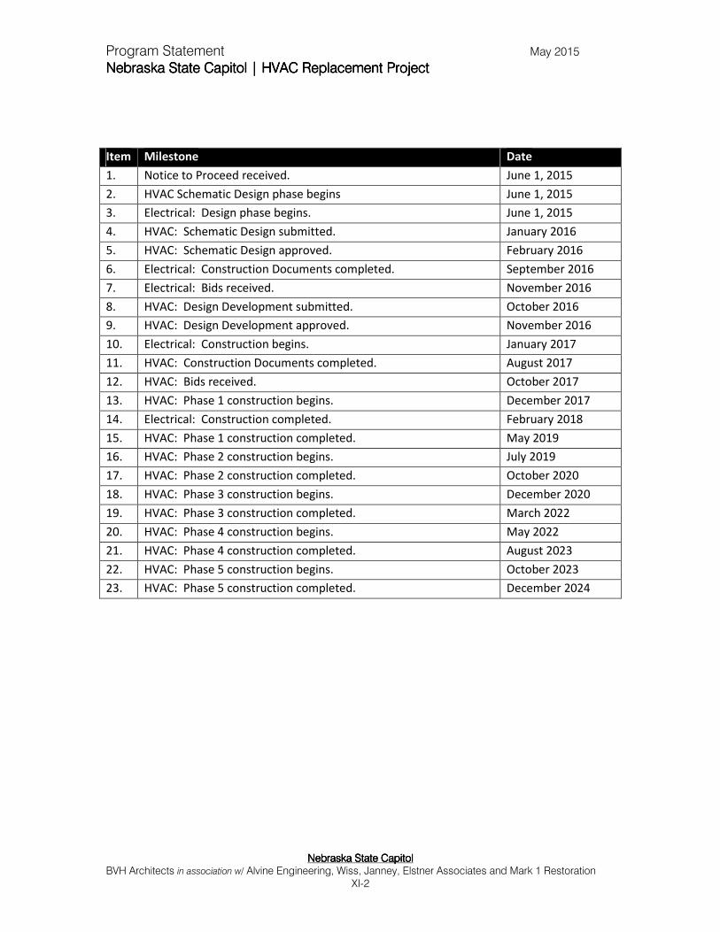
Program Statement May 2015
Nebraska State Capitol | HVAC Replacement Nebraska State Capitol | HVAC Replacement Nebraska State Capitol | HVAC Replacement Nebraska State Capitol | HVAC Replacement ProjectProjectProjectProject
Nebraska State CapitolNebraska State CapitolNebraska State CapitolNebraska State Capitol BVH Architects in association w/ Alvine Engineering, Wiss, Janney, Elstner Associates and Mark 1 Restoration
XI-2
Item Milestone Date
1. Notice to Proceed received. June 1, 2015
2. HVAC Schematic Design phase begins June 1, 2015
3. Electrical: Design phase begins. June 1, 2015
4. HVAC: Schematic Design submitted. January 2016
5. HVAC: Schematic Design approved. February 2016
6. Electrical: Construction Documents completed. September 2016
7. Electrical: Bids received. November 2016
8. HVAC: Design Development submitted. October 2016
9. HVAC: Design Development approved. November 2016
10. Electrical: Construction begins. January 2017
11. HVAC: Construction Documents completed. August 2017
12. HVAC: Bids received. October 2017
13. HVAC: Phase 1 construction begins. December 2017
14. Electrical: Construction completed. February 2018
15. HVAC: Phase 1 construction completed. May 2019
16. HVAC: Phase 2 construction begins. July 2019
17. HVAC: Phase 2 construction completed. October 2020
18. HVAC: Phase 3 construction begins. December 2020
19. HVAC: Phase 3 construction completed. March 2022
20. HVAC: Phase 4 construction begins. May 2022
21. HVAC: Phase 4 construction completed. August 2023
22. HVAC: Phase 5 construction begins. October 2023
23. HVAC: Phase 5 construction completed. December 2024

Program Statement May 2015
Nebraska State Capitol | HVAC Replacement ProjectNebraska State Capitol | HVAC Replacement ProjectNebraska State Capitol | HVAC Replacement ProjectNebraska State Capitol | HVAC Replacement Project
Nebraska Nebraska Nebraska Nebraska State CapitolState CapitolState CapitolState Capitol BVH Architects in association w/ Alvine Engineering, Wiss, Janney, Elstner Associates and Mark 1 Restoration
XII-1
XII.XII.XII.XII. Higher Education SupplementHigher Education SupplementHigher Education SupplementHigher Education Supplement
A. CCPE Review
Not applicable for this project.
B. Method of Contracting
1. Identification of Method
Design/Bid/Build
The preference of the OCC is to utilize the traditional Design/ Bid/ Build (DBB) project
delivery method that contains a process to prequalify general contractors and bidders
to assure that they have the expertise, experience and means to complete this type of
project.
2. Rationale for Method Selection
Bidding by a prequalified list of General Contractors has proven historically to be a
cost effective method of achieving competitive pricing yielding high quality for projects
of similar scope. The design team and OCC have found this method suitable for an
anticipated level of quality, price, schedule and construction methods for the Capitol
HVAC Replacement Project.