
Program - RS Components...
24
1 www.helioprotection.com Program Solar solutions designed by Ferraz Shawmut Power conversion Power generation & distribution Industrial controls Power quality Transportation issue 4 FERRAZ SHAWMUT IS NOW
Transcript of Program - RS Components...

1
www.helioprotection.com
ProgramSolar solutions designed by Ferraz Shawmut
Power conversion Power generation& distribution
Industrialcontrols
PowerqualityTransportation
issue 4
FERRAZ SHAWMUT IS NOW

2
A free, renewableand universal source of energy
Ferraz Shawmut is the electrical protection activity of the global Carbone Lorraine group, which is also involved in photovoltaics through production of the graphite for the molds used to make PV cells.
What with rising gas and oil prices on the one hand, and incentives and tax breaks for a technology that is booming on the other, solar energy is on a roll. By 2020 installed capacity in solar power is expected to be near 300 GW, 50 times as much as in 2006!
This type of system uses an entirely cost-free, globally available energy source to generate electricity for use on the spot, or to sell to the grid. It’s an extremely reliable process – as long as it’s properly protected!
Any installation, whether it’s a stand-alone solar array with a back-up generator set or a grid-connected one, is vulne-rable to fault currents or lightning. Today fuses and surge arresters are the most effective ways of protecting the wiring and all the electrical equipment in a PV system. But that protection must be designed, dimensioned, tested and adapted to the specific features of solar applications.
At Ferraz Shawmut, the specialist in protection specially designed for power generation and distribution, we are showing our commitment to the development of solar power with a dedicated range of products: combiner boxes, fuses and surge arresters. Fuses shield the cables between strings of modules from damage. The faulty circuits are isolated and the system can keep on generating power.
Known reserves of fossil fuels – today the world’s main energy resource – will be depleted by the end of this century if we don’t change our ways. In addition, resolutions aimed at reducing the CO2 emissions that are responsible for global
warming, the Kyoto agreement among others, all encourage the development of environmentally friendly renewable energies: hydropower, wind power, bio-mass, geothermal, aerothermal and solar.
in renewable energiesThe boom
of photovoltaicsThe beauties
is committedFerraz Shawmut

Ferraz Shawmut •Solar solutions 3
Fuses designed for solar photovoltaic
Designed to clear low fault currentsPV cells and panels are d.c. generators. Fuses used to protect loads powered by the alternating current in large grids react to very high fault currents, but the ones used in photovoltaics are very different. Ferraz Shawmut has taken a position on this fast-growing market with specific products that can clear fault currents as small as 2 to 3 times rated current – and that takes cutting edge design and expertise.Ferraz Shawmut has designed an offe-ring dedicated to this booming market with specific components and systems including the Helio Fuse range.
Tried and tested in real-life conditionsOperating conditions for fuses are actually more severe when fault currents are low than when they are high, in a circuit where breaking is required under direct voltage. Ferraz Shawmut has made that effort through extensive work at our labs in Newburyport (USA) and Saint-Bonnet-de-Mure (France).
Essential to know...When a fault occurs in a DC circuit, the absence of natural voltage zero makes
the interruption of DC faults more diffi-cult than the interruption of AC faults as only the fuse arc will force the current to decrease to zero.The correct inter-ruption depends on three parameters: the value of the DC voltage, the value of the ratio L/R (time constant) of the fault path and the value of the fault current. The possible low level of over-load to be eliminated in photovoltaic equipment is a very arduous condition for a fuse! Consequently, special photo-voltaic fuses – Helio Fuses – are desi-gned by Ferraz Shawmut in order to ensure people safety and photovoltaic circuit protection.
Installation with 1 to 3 strings of modulesThe fault current is very slightly higher the operating current: for 1, 2, 3 parallel chains, the fusing is not necessary. Sizing the cables of the module strings in order they withstand the maximum fault current is enough to prevent any fire hazard.
Installation with at least 4 strings of modulesIn this configuration the fault current - in any case largely lower than the short cir-cuit currents in conventional power sour-ces - can reach a level capable of heating and damaging the insulators. In a photo-
100
30
600 700
DCNH
DCT
DC120
800 900 1000 1100 1200 1300
200
300
400
500
In(A)
UDC(V)ATM / ATMR DC10
voltaic equipment neither the polarities+ nor the polarities - are grounded. Each + and - polarities must be equipped with a fuse for ensuring the best protection of people servicing the panels and the equi-pment as well.
How to choose the correct range of fuses?The choice is done with the compliance of the subsequent rule: Maximum DC Opera-ting Voltage of the fuse in the leaflet must be higher than or equal to 1.20 x M x (Voc STC).
How to choose the correct rating of the fuse:A - Fuse current rating determination in Europe and others temperate areas. Rated current In of the fuse must be higher than or equal to 1.27 x Isc STC.B - Fuse current rating determination in Africa and Equatorial or tropical areas. Rated current In of the fuse must be higher than or equal to 1.51 x Isc STC.

4
Systems made to measure for your solar application(grid-connected)
Specialist in interruption of electrical current for a long time, Ferraz Shawmut has designed a wide offering of protections dedicated to solar photovoltaic application market: solar farm, installation for residential, commercial and industrial buildings.
These functional solutions enable to package systems totally fitted to your installation: in our Helio Box program encompassing junction box (on DC side), main box (on DC side) and surge protection box (on DC and AC sides).The photovoltaic application requires DC protection components especially designed and tested. To benefit from a full protection of your installation, we strongly recommend to use our Helio Fuses which have been especially designed to meet the very demanding requirements of this specific application.
Be your own designer of systemOffering is built around key functions:
Clippingwith our fail-safe Surge Trap SPD’s with the patented TPMOV technology inside.These AC or DC devices comply with the IEC 61643-1 standard
We market a standard offering of Helio Box.When the volume is enough high we are able to design Helio Box systems as per your specifications.
Isolating/Protectingthe photovoltaic chains with our Helio Fuse designed to this need and tested on our test platforms.
Signallingwith our remote control and signalling solutions.
Switching/Disconnectingwith our Helio Switch range especially designed for the DC conditions of the PV application.

Ferraz Shawmut • Solar solutions 5
Systems made to measure for your solar application(grid-connected)
Ensuring the safety of solar power generating facilities is a tricky business, because there are very specific risks inherent to that kind of electrical equipment. In fact, the fact that a solar device is both a d.c. environment and a non interruptible source of current is pretty complicated compared to the a.c. world we’re used to. So standards are critical to guaranteeing the safety of people and property.
There are already international standards to govern PV equipment and arrays - IEC 60364-7-712 is devoted to generating systems using solar power, and IEC 62548 Edition 1 covers the safety and installation of PV generators - but there are also more local stan-dards or recommendations such as the UTE’s C15 712 Guidelines in France.
Ferraz Shawmut is a global company delivering high performance technical solutions and quality service to demanding markets. We at Ferraz Shawmut are showing our commitment by getting actively involved in the standardizing process. We are a member of International Electrical Commission (IEC) group 32B, working on section 6 of standard 60269 that deals with additional requirements for low voltage fuses designed to protect photovoltaic power systems (scheduled to be released at the end of 2010).
Ferraz Shawmut gets involved in standardization for solar arrays

6
1 - Determination and total capacity
Precise if it’s a ground-mounted or a roof-mounted solar array and its total capacity.
2 - Wiring diagramMake a simplified diagram showing:> the number of strings (rows of
modules connected in series)> the number of strings connected
of all the junction boxes (Helio Junction Box)
> number of inlets of all the main boxes ( Helio Main Box)
> locations and descriptionsof any switches (Helio Switch)
> locations and descriptionsof the surge protective devices (Surge Trap)
Precise:> the cross sectional areas of cables
into and out of the boxes> the outside diameter of those
cables to check dimensions and choose adequate glands
3 - Type of solar panel used
Precise:> the panel model> what is the module’s Voc STC1
(open circuit voltage)?> what is the module’s Isc STC1
(short circuit current)?
4 - EquipmentPrecise:> the number of modules connected
in series per string> the number of strings connected
in parallel per type of junction box> the ambien temperature around
the junction boxes and main boxes
5 - Optional functionsyour needs for current monitoring:> blown-fuse indicator light on each
fuse holder on the + and - polarities at the outlets from strings
your needs of surge protective devices monitoring2:> Surge Trap Pluggable> Surge Trap non Pluggable
(Modular)
1) STC = Standard Test Conditions irradiance 1000W/m2
air mass = 1.5 cell temperature 25°C
2) Surge Traps all have a visual end-of-life indicator; a built-in microswitch transmitting end-of-life data remotely is one option.
Offering the system meeting precisely your needs is our concern. Ferraz Shawmut introduces a 5-point information form on your solar PV installation (connected to the low voltage utility grid). This form can be downloaded on our web site dedicated to solar PV www.helioprotection.com
Determine how to protect your own solar array

Ferraz Shawmut •Solar solutions 7
Technical specification For 1 string
Colour RAL 7035
Degree of protection IP66
Impact strength 6 Joule
Material base Self-extinguishing thermoplastic
Cover Smoked with key locking
Operating temperature -25°C/+85°C
Size LxlxH (mm) 190x112x106
Standard IEC 23-48 & 23-49 & 60670
Technical specification For 2 to 3 strings
Colour RAL 7035
Content Enclosure base, cover, cover screws, mounting screws
Degree of protection IP66, IP67
Impact strength IK 07/IK 06
Inner depth (mm) 115,0
Material base ABS
Material, cover Polycarbonate
Material, cover screws Polyamide
Material, gasket Polyurethane
Operating temperature -40°C/+90°C
Outer cover height (mm) 30
Size LxlxH (mm) 200x300x132
Standard EN 62208, GOST
Volume cm3 792,00
Weight (kg) 1,218
Box Strings
HSPD Surge Protective Devices (SPD) XX
Helio Surge Protection Box S if SPD Modular Number of strings
SP if SPD Pluggable 01 = 1 string
6 = 600 VDC 02 = 2 strings
10 = 1000 VDC 03 = 3 strings
M = microcontact
ex: HSPDSP10M02 HSPD SP10M 02
Helio Surge Protection Box Surge Trap Pluggable 1000V DC with microswitch 2 strings
190
97,5
112
4 DIN
10645,914,4
2,5
41
300 [11.81]123 [4.84]115 [4.53]3.5 [0.14]8 [0.32]
Ø 4
.2 [
0.17
]
200
[7.8
7]
101.
5 [4
]
Ø 10 [0.39]
27 [
1.06
]
Ø 7.5 [0.3]
131.
5 [5
.18]
30 [
1.18
]
Helio Surge Protection Box
Product offering
Define your catalog number

8
Helio Junction Box
ABS, polycarbonate transparent cover
Number of string 4 to 6 8 to 12
Nominal Voltage 1000VDC
Wire cable section for the strings 4mm² reinforced isolation
Closed stuffing box size PG9 (6 to 10mm)
Finger safe protection (IEC 60529) IP65 (Outdoor installation)
Isolation Class (IEC 60364) II
Fire and fumes class (UL94 - NFC 20-455) V2
Dimensions (HxLxP) see next page
Colour RAL 7035
Cable wire recommended for output 10mm² (PGxxx) 25mm² (PGxxx)
Maximum usage temperature - 20°C to + 50°C
Maximum storage temperature - 20°C to + 70°C
Relative Humidity 95% Maxi
Maximum current 72A 100ALabelling ATTENTION: Permanent VOLTAGE higher than 50V
Permanent DC voltage equipment Disconnection and Protection DO not operate under load
Wiring & connecting recommendations
(Use only Helio Modulostar fuse holders designed for PV DC application in our Helio Junction Box)
All connections must be made by personnel qualified to work at voltages over 50V
We recommend wiring the output from the box before the input to the box
Max tightening torque = 2.2Nm on output terminals
Do not operate under load
Max tightening torque = 2.2Nm on input terminals
All connections must be made under stable weather conditions (no rain or lightning)
Helio Junction Box with switch-disconnector
Our Helio Junction Box can be equipped with switch-disconnectors (see on the right). Please contact our Technical Support (+33 4 26292929) for further questions.
e-mail: [email protected]
Helio Junction BoxProduct offering
Box Strings Fuse holders Surge Protective Devices
Switch- disconnectors
HJB M XX
Helio Junction Box Blank if input/output for fuse holders and SPD's all together
Blank if no indicator Blank if no SPD Blank
if no switch
M if Number of strings S if SPD Modular 1000V switch
one input/output per string for fuse holder and SPD 04 SP if SPD Pluggable IT25 (25A)
06 I (INDICATOR) 6 = 600 VDC IT64 (64A)
08 10 = 1000 VDC
10 M = microcontact
12
ex: HJB10S6V HJB 10 6V
Helio Junction Box input/output all together 10 strings Surge Trap SPD
600V
ex: HJB12IS10MIT64 HJB 12 I S10M IT64
Helio Junction Box input/output all together 12 strings Fuse holder with indicator
S10MSurge Trap SPD 64A switch
1000V with microswitch
ex: HJBM12IS10M HJB M 12 I S10M
input/output per string 12 strings Fuse holder with indicator Surge Trap SPD
1000V with microswitch

Ferraz Shawmut •Solar solutions 9
Custom Helio Box
When the quantity is large we have the capacity to design custom Helio Box as per your specifications.
Strings 4 6 8 10 12
Modulostar
Modulostar +Surge Trap 200x300x132mm 400x300x132mm
Modulostar +Helio Switch
Modulostar +Helio Switch +Surge Trap 400x300x132mm 600x300x132mm
300 [11.81]
200
[7.8
7] 30 [
1.18
]13
1.5
[5.1
8]10
1.5
[4]
30 [
1.18
]
131.
5 [5
.18]
101.
5 [4
]
Ø7.5 [0.3]
27 [
1.06
]
Ø10 [0.39]
Ø7.5 [0.3]
27 [
1.06
]
Ø10 [0.39]
Ø7.5 [0.3]
27 [
1.06
]
Ø10 [0.39]
400 [15.75]
300
[11.
81]
600 [23.62]
300
[11.
81]
30 [
1.18
]
131.
5 [5
.18]
101.
5 [4
]
200x300x132mm
400x300x132mm
600x300x132mm
Helio Junction BoxProduct offering

10
0,0001
10 100 1000 10000
0,001
0,01
0,1
1
100
1000
10000
10
Feature> Fast Acting> Highly current limiting> High breaking capacities> Very low I²t> Superior cycling ability> Withstanding in overloads
Application
> Fuse for photovoltaic string protection in accordance with UTE 15 712.
Packaging
Complying> IEC 60269-1 & IEC 60269-4
Basics characteristics
SizeMaximum operating voltage
for L/R ≤ 0,5ms
RatedCurrent Operation
Minimum value of the
breaking capacity
Breaking Capacity
@ UnPrearcing I²t @ 1ms
Total I²t @ Un
Power losses End contacts
Catalog number0.7In 0.8In
mm V A
“g”type
A kA A2s A2s W W
D10xL851 200
12,5 16,5
11
180 310 1,3 1,9 DC10HEL12C12,5
16 21 370 680 1,5 2,1 DC10HEL12C16
20 26 630 1080 1,8 2,5 DC10HEL12C20
900 25 32,5 990 1680 2,2 3 DC10HEL9C25
Other ratings available on request.
0.4
P/P0,7In
0.45 0.5 0.55 0.6 0.65 0.7 0.75 0.8 I/In
0.9
1.0
1.1
1.2
0 10 20 30 40 50 60 70
P(T)/P(20)
Ta (°C)
Corrective factor for power losses vs. ambient temperature
0.20
0.40
0.60
0.80
1.00
1.20
1.40
Poids : 11 g
> Box: 45 pieces> Pack: 95 x 82 x 70> Weight : 520 g
HelioFuse DC10 - 1200VDC
Product offering
Drawing

Ferraz Shawmut •Solar solutions 11
0.4
P/P0,7In
0.45 0.5 0.55 0.6 0.65 0.7 0.75 0.8 I/In
0.9
1.0
1.1
1.2
0 10 20 30 40 50 60 70
P(T)/P(20)
Ta (°C)
Corrective factor for power losses vs. ambient temperature
0.20
0.40
0.60
0.80
1.00
1.20
1.40
Fuse clips
Cat. Number Designation Weight (g) Pack
MR10RESSORTCI MR10 CI 4.5 200
MR10RESSORT MR10 7.0 20
MR10RESSORTSP MR10 without compressor 5.7 20
Cat. Number Losses 70% Rated (Watts)
DCT1-2 0.1
DCT2-2 0.15
DCT3-2 0.35
DCT4-2 0.4
DCT5-2 0.5
DCT8-2 0.52
DCT10-2 0.7
DCT12-2 0.75
DCT15-2 1
DCT20-2 1.5
DCT25-2 1.5
DCT30-2 1.8
Minimum breaking capacity = 1.3 In for DCT models from 1 to 5A and 2 In for DCT models from 8 to 20A.Maximum breaking capacity = 50 kA
Maximum operating voltage Rated Current Cat. Number Packaging
1 000VDC @L/R = 2ms 1 DCT1-2 10
2 DCT2-2 10
3 DCT3-2 10
4 DCT4-2 10
5 DCT5-2 10
8 DCT8-2 10
10 DCT10-2 10
12 DCT12-2 10
15 DCT15-2 10
20 DCT20-2 10
25* DCT25-2 10
30* DCT30-2 10
* Minimum breaking capacity is 3In.
1.531.01 [38.9]
MOUNTING HOLE DETAIL
Ø .05 [1.3]4 PLCS
PCF1-H thru PCF30-H
.03 [.8]
.20 [5.1]
.05 [1.4]
.50 [12.6]
TAB TO
Ø .41 [10.5]
MAX. REF
.15 [3.8]
.05 [1.2]
.20 [5.1]
FOR .062 (1.6) NOMINALCIRCUIT BOARD
THICKNESS
Double Hole Mount (Round Holes)
DCT
1-1/2”(38.1 mm)
13/32”(10.3 mm)
HelioFuseDCT - 1000VDC - (10x38mm)
Product offering
Electrical characteristicsDrawing
PC-mount version as per this drawing is also available (consult us).
10.1
Ø 4.2
914
15.520.5
0.8
14
15.520.5
10.1
Ø 4.2
270.8
Ø 5.5
157
12
5
15
6
6.35
16
0.8
Ø 10.3 14.65.3
12.7
1.9
MR10 CI MR10 without compressorMR10
12
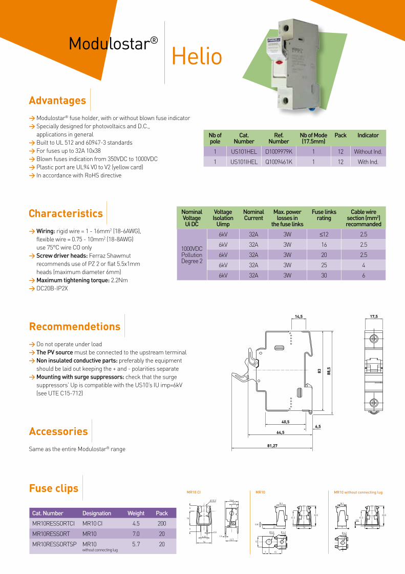
Nb ofpole
Cat. Number
Ref. Number
Nb of Mode (17.5mm)
Pack Indicator
1 US101HEL D1009979K 1 12 Without Ind.
1 US101IHEL Q1009461K 1 12 With Ind.
NominalVoltageUi DC
VoltageIsolation
Uimp
NominalCurrent
Max. powerlosses in
the fuse links
Fuse linksrating
Cable wiresection (mm2)recommanded
1000VDCPollutionDegree 2
6kV 32A 3W ≤12 2.5
6kV 32A 3W 16 2.5
6kV 32A 3W 20 2.5
6kV 32A 3W 25 4
6kV 32A 3W 30 6
14,5 17,5
40,5
64,56,5
81,27
83 88,5
Cat. Number Designation Weight Pack
MR10RESSORTCI MR10 CI 4.5 200
MR10RESSORT MR10 7.0 20
MR10RESSORTSP MR10 without connecting lug
5.7 20
HelioModulostar®
Advantages> Modulostar® fuse holder, with or without blown fuse indicator> Specially designed for photovoltaics and D.C.,
applications in general> Built to UL 512 and 60947-3 standards> For fuses up to 32A 10x38> Blown fuses indication from 350VDC to 1000VDC> Plastic port are UL94 V0 to V2 (yellow card)> In accordance with RoHS directive
Recommendetions> Do not operate under load> The PV source must be connected to the upstream terminal> Non insulated conductive parts: preferably the equipment
should be laid out keeping the + and - polarities separate> Mounting with surge suppressors: check that the surge
suppressors’ Up is compatible with the US10’s IU imp=6kV (see UTE C15-712)
AccessoriesSame as the entire Modulostar® range
Characteristics> Wiring: rigid wire = 1 - 16mm2 (18-6AWG),
flexible wire = 0.75 - 10mm2 (18-8AWG)use 75°C wire CO only
> Screw driver heads: Ferraz Shawmutrecommends use of PZ 2 or flat 5.5x1mm heads (maximum diameter 6mm)
> Maximum tightening torque: 2.2Nm> DC20B-IP2X
Fuse clips10.1
Ø 4.2
914
15.520.5
0.8
14
15.520.5
10.1
Ø 4.2
270.8
Ø 5.5
157
12
5
15
6
6.35
16
0.8
Ø 10.3 14.65.3
12.7
1.9
MR10 CI MR10 without connecting lugMR10

Ferraz Shawmut •Solar solutions 13
Electrical characteristics
ATM
1-1/2”(38.1 mm)
13/32”(10.3 mm)
Minimum Breaking Capacity = 1.35In ; Maximum Breaking Capacity = 100kA
Max.Operating Voltage = Rated Voltage Rated Current
Cat. Number Packaging
600VDC UL/CSA @ L/R = 10ms
5 ATM5 10
8 ATM8 10
10 ATM10 10
15 ATM15 10
20 ATM20 10
25 ATM25 10
30 ATM30 10
5 PCF5-H 10
8 PCF8-H 10
10 PCF10-H 10
15 PCF15-H 10
20 PCF20-H 10
25 PCF25-H 10
30 PCF30-H 10
Cat. Number Watt Losses @ 0.7In & 20°C
ATM5 0.6
ATM8 0.7
ATM10 0.75
ATM15 0.8
ATM20 1
ATM25 1.1
ATM30 1.2
0.4
P/P0,7In
0.45 0.5 0.55 0.6 0.65 0.7 0.75 0.8 I/In
0.9
1.0
1.1
1.2
0 10 20 30 40 50 60 70
P(T)/P(20)
Ta (°C)
Corrective factor for power losses vs. ambient temperature
0.20
0.40
0.60
0.80
1.00
1.20
1.40
For UL fuses, the maximum operating voltage is equal to the rated voltage.Other ratings are available (consult us).
HelioFuseATM - 600VDC
Product offering
Fuse holders
Drawing
Nb ofpole
Cat. Number
Ref. Number
Nb of Mode (17.5mm)
Pack Indicator
1 US101HEL D1009979K 1 12 Without Ind.
1 US101IHEL Q1009461K 1 12 With Ind.
PCF Double Hole Mount (Round Holes)
1.531.01 [38.9]
MOUNTING HOLE DETAIL
Ø .05 [1.3]4 PLCS
PCF1-H thru PCF30-H
.03 [.8]
.20 [5.1]
.05 [1.4]
.50 [12.6]
TAB TO
Ø .41 [10.5]
MAX. REF
.15 [3.8]
.05 [1.2]
.20 [5.1]
FOR .062 (1.6) NOMINALCIRCUIT BOARD
THICKNESS

14
Minimum Breaking Capacity = 1.35In ; Maximum Breaking Capacity = 100kA
Max.Operating Voltage = Rated Voltage Rated Current
Cat. Number Packaging
600VDC @ L/R = 10ms
5 ATMR5 10
8 ATMR8 10
10 ATMR10 10
15 ATMR15 10
20 ATMR20 10
25 ATMR25 10
30 ATMR30 10
.12(3.2)
1.50 (38.1)
.25 DIA(6.44)
.41 DIA(10.4)
Cat. Number Watt Losses @ 0.7In & 20°C
ATMR5 0.6
ATMR8 0.7
ATMR10 0.75
ATMR15 0.8
ATMR20 1
ATMR25 1.1
ATMR30 1.2
Cat. Number Number of poles Indicator Packaging Udc maxi operating
USBCC101 1 No 12 600 V
USBCC101I 1 Yes 12 600 V
0.4
P/P0,7In
0.45 0.5 0.55 0.6 0.65 0.7 0.75 0.8 I/In
0.9
1.0
1.1
1.2
0 10 20 30 40 50 60 70
P(T)/P(20)
Ta (°C)
Corrective factor for power losses vs. ambient temperature
0.20
0.40
0.60
0.80
1.00
1.20
1.40
For UL fuses, the maximum operating voltage is equal to the rated voltage.
Electrical characteristics
HelioFuseATMR - 600VDC
Fuse holders
Drawing
Product offering

Ferraz Shawmut •Solar solutions 15
Maximum cable cross section (copper wires)
Rating Catalog Number pre-connected Operational voltage (V)
Open-circuit maximum voltage (V)
Rated insulation voltage (V) Use category
25A IT25HEL10CCF yes
800 920 1000 DC21A* 32A IT32HEL10CCF yes
40A IT40HEL10CCF yes
70A IT70HEL10CCF yes
80A IT70HEL10CCF yes 600 600 600 DC21A*
IT25HEL10CCF IT32HEL10CCF IT40HEL10CCF IT70HEL10CCF
Single-core or stranded wire 6mm2 6mm2 16mm2 50mm2
Flexible wire 4mm2 4mm2 10mm2 35mm2
Recommended torque values 1.25 Nm 1.25 Nm 1.8 Nm 3 Nm
Helio SwitchProduct offering
These switch-disconnectors comply with IEC 60947-3 and VDE 0660 part 107. Typically, they are used as switch for isolating a group of strings of modules (consult us). They have a small footprint. The poles are pre-connected in series.Connections are IP20 protected IP20. These Helio Switch are equipped to be mounted on DIN-rail. They must be installed and verified by authorized people who know very well the rules to be applied in solar PV equipment.
All our Helio Switch are equipped with guaranteed shunts providing time savings in the mounting process and improved safety.
* For PV application and interrupting DC
F3 F1A
26
26K
5
F4
Input Input+
Output+ - -
F2
G H
E4.
1
45.4
F3 F1
45
A
34
34K
5G HF4 F2
E5.
2
Inpout Input+
Output+ - -
N N
1T3
Output
Input
Wir
ing
diag
ram
2T1
+ -
+ -
N N
1T3
Output
Input
Wir
ing
diag
ram
2T1
+ -
+ -IT32HELI0CCF
Advided tightening torque
1,25 NmIT32HELI0CCF 1,80 Nm
IT32HEL10CCFIT40HEL10CCF
A
Dim
ensi
ons
EF1F2F3F4GHKL
43,760321023,545,511154649
64
105,47037,512,528,553,5132
62,510
IT70HEL10CCF
709047,522,544,569,51848076,214 Pe
elin
g Le
nght
IT32HEL10CCFIT40HEL10CCF
IT70HEL10CCF
16
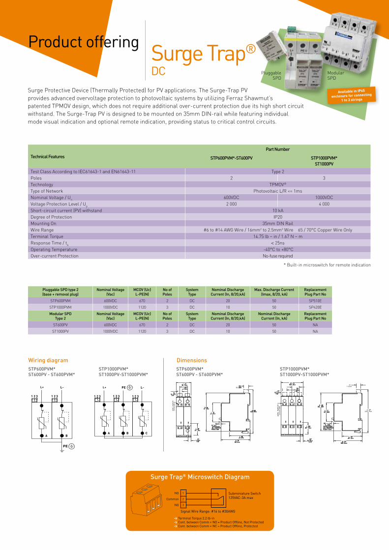
* Built-in microswitch for remote indication
Surge Protective Device (Thermally Protected) for PV applications. The Surge-Trap PV provides advanced overvoltage protection to photovoltaic systems by utilizing Ferraz Shawmut’s patented TPMOV design, which does not require additional over-current protection due its high short circuit withstand. The Surge-Trap PV is designed to be mounted on 35mm DIN-rail while featuring individual mode visual indication and optional remote indication, providing status to critical control circuits.
STP600PVM*ST600PV - ST600PVM*
STP1000PVM*ST1000PV-ST1000PVM*
STP600PVM*ST600PV - ST600PVM*
STP1000PVM*ST1000PV-ST1000PVM*
DimensionsWiring diagram
Pluggable SPD type 2 (base + removal plug)
Nominal Voltage(Vac)
MCOV (Uc) L-PE(N)
No of Poles
SystemType
Nominal Discharge Current (In, 8/20,kA)
Max. Discharge Current (Imax, 8/20, kA)
Replacement Plug Part No
STP600PVM 600VDC 670 2 DC 20 50 SP510E
STP1000PVM 1000VDC 1120 3 DC 10 50 SP420E
Modular SPD Type 2
Nominal Voltage(Vac)
MCOV (Uc) L-PE(N)
No of Poles
SystemType
Nominal Discharge Current (In, 8/20,kA)
Nominal DischargeCurrent (In, kA)
Replacement Plug Part No
ST600PV 600VDC 670 2 DC 20 50 NA
ST1000PV 1000VDC 1120 3 DC 10 50 NA
Product offering
Technical Features
Part Number
STP600PVM*-ST600PV STP1000PVM*ST1000PV
Test Class According to IEC61643-1 and EN61643-11 Type 2Poles 2 3Technology TPMOV®
Type of Network Photovoltaic L/R <= 1msNominal Voltage / Un 600VDC 1000VDCVoltage Protection Level / Up 2 000 4 000Short-circuit current (PV) withstand 10 kADegree of Protection IP20Mounting On 35mm DIN RailWire Range #6 to #14 AWG Wire / 16mm2 to 2.5mm2 Wire 65 / 70°C Copper Wire OnlyTerminal Torque 14.75 lb – in / 1.67 N – mResponse Time / tA < 25nsOperating Temperature -40°C to +80°COver-current Protection No-fuse required
Available in IP65
enclosure for connecting
1 to 3 strings
Pluggable SPD
Modular SPD
NO 1
Common 2
NO 3
Subminiature Switch125VAC-3A max
Signal Wire Range: #16 to #30AWG
Surge Trap® Microswitch Diagram
> Terminal Torque 2.2 lb-in> Cont. between Comm + NO = Product Offline, Not Protected> Cont. between Comm + NC = Product Offline, Protected
Surge Trap®
DC
hlp
Zone de texte
/ IscwPV
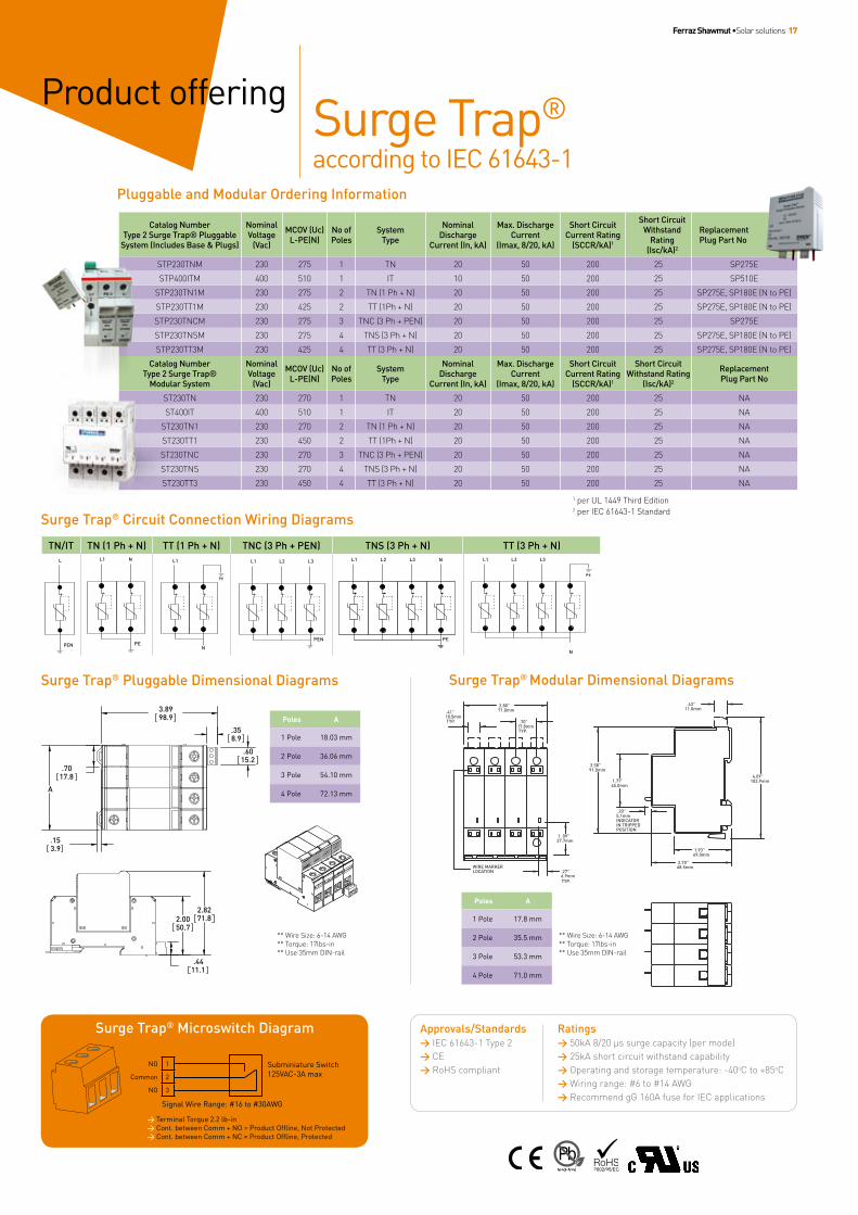
Ferraz Shawmut •Solar solutions 17
Surge Trap®
according to IEC 61643-1
Product offering
.43”11.0mm
.20”5.1mmINDICATORIN TRIPPEDPOSITION
2.70”68.5mm
1.93”49.0mm
4.09” 103.9mm
3.58” 91.0mm
1.77”45.0mm
.41”10.5mm TYP.
.27”6.9mm
1. 09”27.7mm
2.80”71.0mm
.70”17.8mm TYP.
WIRE MARKERLOCATION
TYP.
Pluggable and Modular Ordering Information
Surge Trap® Modular Dimensional Diagrams
Poles A
1 Pole 17.8 mm
2 Pole 35.5 mm
3 Pole 53.3 mm
4 Pole 71.0 mm
Surge Trap® Pluggable Dimensional Diagrams
2.8271.82.00
50.7
.4411.1
3.8998.9
.153.9
.358.9
.6015.2
.7017.8
A
Poles A
1 Pole 18.03 mm
2 Pole 36.06 mm
3 Pole 54.10 mm
4 Pole 72.13 mm
Catalog NumberType 2 Surge Trap® Pluggable
System (Includes Base & Plugs)
Nominal Voltage
(Vac)
MCOV (Uc) L-PE(N)
No of Poles
SystemType
Nominal Discharge
Current (In, kA)
Max. Discharge Current
(Imax, 8/20, kA)
Short Circuit Current Rating
(SCCR/kA)1
Short Circuit Withstand
Rating (Isc/kA)2
Replacement Plug Part No
STP230TNM 230 275 1 TN 20 50 200 25 SP275E
STP400ITM 400 510 1 IT 10 50 200 25 SP510E
STP230TN1M 230 275 2 TN (1 Ph + N) 20 50 200 25 SP275E, SP180E (N to PE)
STP230TT1M 230 425 2 TT (1Ph + N) 20 50 200 25 SP275E, SP180E (N to PE)
STP230TNCM 230 275 3 TNC (3 Ph + PEN) 20 50 200 25 SP275E
STP230TNSM 230 275 4 TNS (3 Ph + N) 20 50 200 25 SP275E, SP180E (N to PE)
STP230TT3M 230 425 4 TT (3 Ph + N) 20 50 200 25 SP275E, SP180E (N to PE)
Catalog NumberType 2 Surge Trap®
Modular System
Nominal Voltage
(Vac)
MCOV (Uc) L-PE(N)
No of Poles
SystemType
Nominal Discharge
Current (In, kA)
Max. Discharge Current
(Imax, 8/20, kA)
Short Circuit Current Rating
(SCCR/kA)1
Short Circuit Withstand Rating
(Isc/kA)2
Replacement Plug Part No
ST230TN 230 270 1 TN 20 50 200 25 NA
ST400IT 400 510 1 IT 20 50 200 25 NA
ST230TN1 230 270 2 TN (1 Ph + N) 20 50 200 25 NA
ST230TT1 230 450 2 TT (1Ph + N) 20 50 200 25 NA
ST230TNC 230 270 3 TNC (3 Ph + PEN) 20 50 200 25 NA
ST230TNS 230 270 4 TNS (3 Ph + N) 20 50 200 25 NA
ST230TT3 230 450 4 TT (3 Ph + N) 20 50 200 25 NA
1 per UL 1449 Third Edition2 per IEC 61643-1 Standard
** Wire Size: 6-14 AWG** Torque: 17lbs-in** Use 35mm DIN-rail
** Wire Size: 6-14 AWG** Torque: 17lbs-in** Use 35mm DIN-rail
Surge Trap® Circuit Connection Wiring Diagrams
TN/IT TN (1 Ph + N) TT (1 Ph + N) TNC (3 Ph + PEN) TNS (3 Ph + N) TT (3 Ph + N)
NO 1
Common 2
NO 3
Subminiature Switch125VAC-3A max
Signal Wire Range: #16 to #30AWG
Surge Trap® Microswitch Diagram
> Terminal Torque 2.2 lb-in> Cont. between Comm + NO = Product Offline, Not Protected> Cont. between Comm + NC = Product Offline, Protected
Approvals/Standards> IEC 61643-1 Type 2 > CE > RoHS compliant
Ratings> 50kA 8/20 μs surge capacity (per mode) > 25kA short circuit withstand capability > Operating and storage temperature: -40oC to +85oC > Wiring range: #6 to #14 AWG> Recommend gG 160A fuse for IEC applications
R10
6
A
9,5P
CT
B
6
A
9,5P
CT
B
NM
L
N
H
M
L
R10
H
0.4
P/P0,7In
0.45 0.5 0.55 0.6 0.65 0.7 0.75 0.8 I/In
0.9
1.0
1.1
1.2
0 10 20 30 40 50 60 70
P(T)/P(20)
Ta (°C)
Corrective factor for power losses vs. ambient temperature
0.20
0.40
0.60
0.80
1.00
1.20
1.40
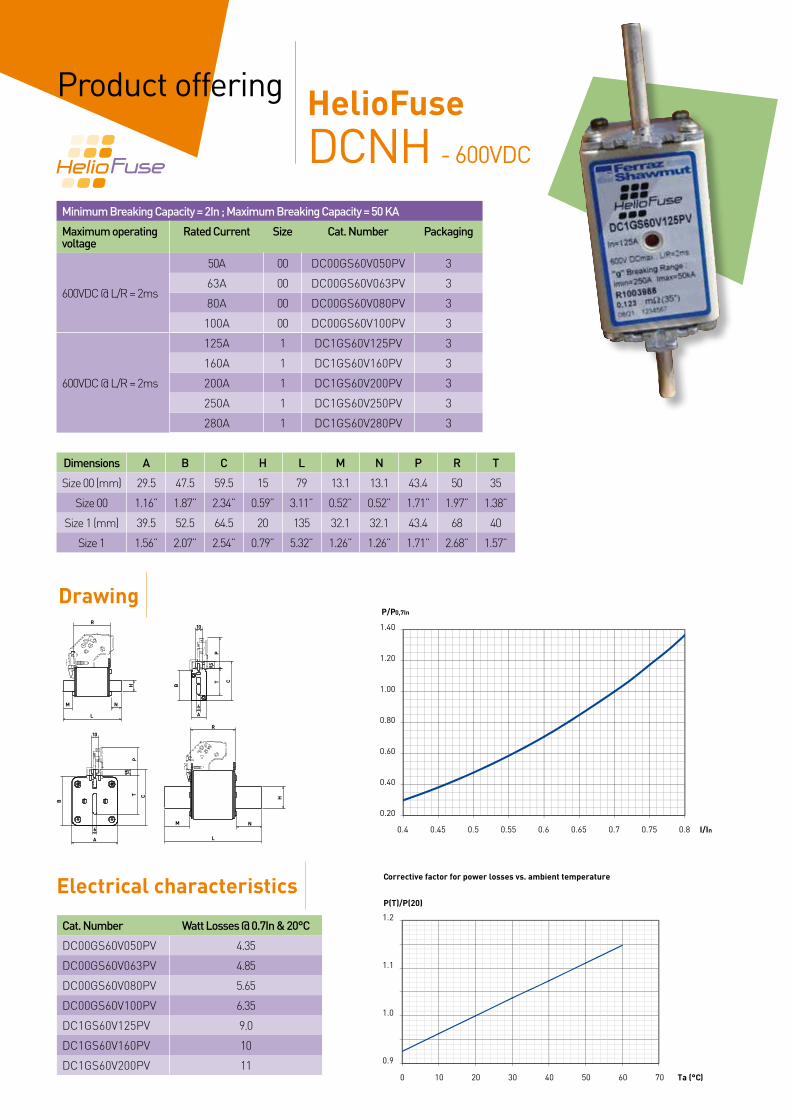
18
HelioFuseDCNH - 600VDC
Product offering
Minimum Breaking Capacity = 2In ; Maximum Breaking Capacity = 50 KA
Maximum operatingvoltage
Rated Current Size Cat. Number Packaging
600VDC @ L/R = 2ms
50A 00 DC00GS60V050PV 3
63A 00 DC00GS60V063PV 3
80A 00 DC00GS60V080PV 3
100A 00 DC00GS60V100PV 3
600VDC @ L/R = 2ms
125A 1 DC1GS60V125PV 3
160A 1 DC1GS60V160PV 3
200A 1 DC1GS60V200PV 3
250A 1 DC1GS60V250PV 3
280A 1 DC1GS60V280PV 3
Cat. Number Watt Losses @ 0.7In & 20°C
DC00GS60V050PV 4.35
DC00GS60V063PV 4.85
DC00GS60V080PV 5.65
DC00GS60V100PV 6.35
DC1GS60V125PV 9.0
DC1GS60V160PV 10
DC1GS60V200PV 11
Dimensions A B C H L M N P R T
Size 00 (mm) 29.5 47.5 59.5 15 79 13.1 13.1 43.4 50 35
Size 00 1.16” 1.87” 2.34” 0.59” 3.11” 0.52” 0.52” 1.71” 1.97” 1.38”
Size 1 (mm) 39.5 52.5 64.5 20 135 32.1 32.1 43.4 68 40
Size 1 1.56” 2.07” 2.54” 0.79” 5.32” 1.26” 1.26” 1.71” 2.68” 1.57”
Drawing
Electrical characteristics

Ferraz Shawmut •Solar solutions 19
Cat. Number Fuse size Nb of poles Packaging Model Udc maxi operating
BB001RFS 00 1 3 IP2X Finger Safe including cover
690V
BB11PPRFS 1 1 3 690V
Fuse bases
Remote signalling system for fitting on fuses equipped with micro-switch support.
Accessories
Cat. Number Contact Qty of NO-NC separated circuits Packaging
MSNH2-B6PRES Mini = 20V 50mA • Maxi = 10A 1 3
MSNH2-B2PRES Mini = 20V 100mA • Maxi = 5A 1 3
A MN
J
D H LK
O I
B
GE
FF
Dimensions (mm)
A B C D E F G H I J K L M N O
Size 00 32 20 117 100 8 2 14 25 145 21.5 8 56 52 85 84
Size 1 60 32 209 176 10,5 30 20,5 25 250 35 M10 81 71 122,5 146
20
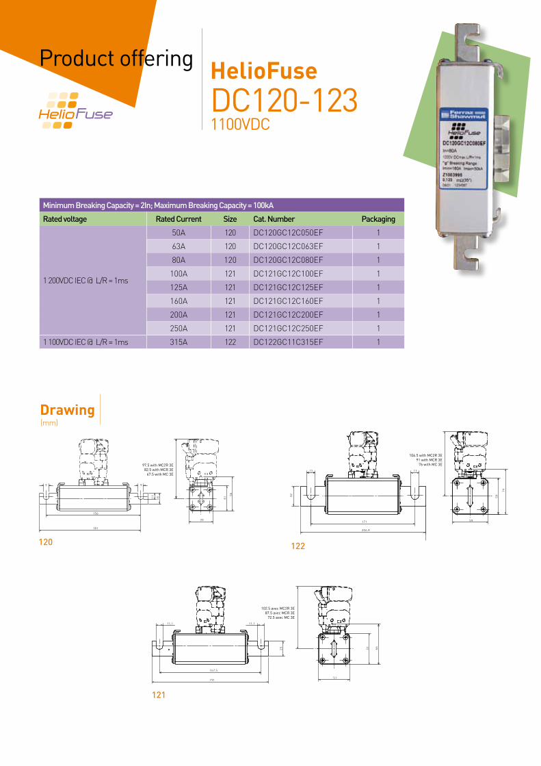
HelioFuseDC120-1231100VDC
Product offering
Minimum Breaking Capacity = 2In; Maximum Breaking Capacity = 100kA
Rated voltage Rated Current Size Cat. Number Packaging
1 200VDC IEC @ L/R = 1ms
50A 120 DC120GC12C050EF 1
63A 120 DC120GC12C063EF 1
80A 120 DC120GC12C080EF 1
100A 121 DC121GC12C100EF 1
125A 121 DC121GC12C125EF 1
160A 121 DC121GC12C160EF 1
200A 121 DC121GC12C200EF 1
250A 121 DC121GC12C250EF 1
1 100VDC IEC @ L/R = 1ms 315A 122 DC122GC11C315EF 1
Drawing
97.5 with MC2R 3E82.5 with MCR 3E
67.5 with MC 3E
102.5 avec MC2R 3E87.5 avec MCR 3E
72.5 avec MC 3E
106.5 with MC2R 3E91 with MCR 3E
76 with MC 3E
120
121
122
(mm)

Ferraz Shawmut •Solar solutions 21
Cat. Number Contact Qty of NO-NC separated circuits
Packaging
MC3E1-5N Mini = 20V 50mA Maxi = 5A
1 1 & 3
MC3E1-5NBS Mini = 10V 10mA Maxi = 3A
1 1 & 3
MC3E1-9NBS 2 1 & 3
Accessories
Cat. Number Nb of poles Packaging Insulation Voltage
SP43-120 1 1
2 500VDCSE43-121 1 1
SE43-122 1 1
Fuse bases
G
P
M
F
B
L
A
D
H
C*
EN
øSøR
G
P
M1410
F
A
L
Q
D
C*
EN
B
H
14 10 øS øR
G
P
M1410
F
A
L
Q
D
C*
EN
B
H
14 10 øS øR
Cat. Number Watt Losses @ 0.7In & 20°C
DC120GC12C050EF 3.4
DC120GC12C063EF 4.4
DC120GC12C080EF 5.6
DC121GC12C100EF 7.0
DC121GC12C125EF 8.8
DC121GC12C160EF 11.3
DC121GC12C200EF 15.7
DC121GC12C250EF 19.6
DC122GC11C315EF 24.3
Remote signalling system for fitting on fuses equipped with micro-switch support.
0.4
P/P0,7In
0.45 0.5 0.55 0.6 0.65 0.7 0.75 0.8 I/In
0.9
1.0
1.1
1.2
0 10 20 30 40 50 60 70
P(T)/P(20)
Ta (°C)
Corrective factor for power losses vs. ambient temperature
0.20
0.40
0.60
0.80
1.00
1.20
1.40
Cat. Number Drawing(mm)
A B C* D E F G H L M N P Q Ø R Ø S
SP43-120 1 194.5 42 125 54.5 26 214.5 134.5 10 234.5 106.5 28 184 8.5 5.5
SE43-121 2 204.5 42 130 54 32 238.5 141.5 10 270.5 116.5 28 191.5 166.5 10.5 5.5
SE43-122 2 230.5 54 140 60 42 260.5 136.5 15 296.5 77.5 35 206.5 171.5 12.5 8.5
Electrical characteristics

22
For large solar power applications at Ferraz Shawmut’s we have the abilities to design and manufacture custom enclosures as per customer specifications.Supplying traction, utilities, power conversion markets, the company has the resources to design and manufacture high-power cubicles.
Custom enclosures Main boxes
DC contactorsProduct offering
In solar farms for power generation many inverters can operate, simultaneously or not. Connecting different solar panels to different inverters should be useful (commute from one inverter to an other, optimize power generation especially in case of low shine level).Commuting DC voltages in the range 500V up to 1500V is necessary.The Lenoir-Elec branded modular contactors of Ferraz Shawmut are part of our Helio Protection program. They are particularly well fitted to this application.
Contactor CBC57-80A CBC57-150A CBC57-200A CBFC55-80A CBFC55-80A CBFC55-80A
Maximumswitch-offvoltage
Pole NO/NC NO/NC NO/NC NO/NC NO/NC NO/NCSingle pole 500VDC 500VDC 500VDC 500VDC 500VDC 500VDC
2-pole 1000VDC 1000VDC 1000VDC 1000VDC 1000VDC 1000VDCControl DC AC
Contactor CBFC75-400A
CBFC75-500A
CBFC75-630A
CBFC75-800A
CBFC75-1000A
Maximumswitch-offvoltage
Single Pole 500VDC 500VDC 500VDC 500VDC NO/NC2-pole 1000VDC 1000VDC 1000VDC 1000VDC 1000VDC3-pole 2000VDC 2000VDC 2000VDC 2000VDC 2000VDC
Control AC (DC consult us)
For rating higher than 1000A up to 8000A consult us.

Ferraz Shawmut •Solar solutions 23
Switch size A IT160 IT200 IT250 IT315 IT400Poles in series 4 6 6 6 6
Rated insulation voltagePollution degree 2 V 1000 1000 1000 1000 1000Pollution degree 3 V 800 1000 1000 1000 1000
Dielectric strength 50 Hz 1min. kV 10 (1) 10 10 10 10Rated impulse with stand voltage kV 12 (1) 12 12 12 12
Rated thermal current, DC-20In open air, normal conditions(2) A 200 200 250 315 400In enclosure 40°C A 160 200 250 315 400In enclosure 60°C A 125 180 200 280 320
...with minimum cable or bar cross section Cu mm² 70 95 120 185 240
Rated operational current / poles in series 750V A 160 / 4 (A)
DC-21B 1000V A 200 / 6 250 / 6 315 / 6 400 / 6Rated short-time withstand current, 1 000 V, 1s R.M.S. - value Icw kA 4 8 8 15 15
Power loss / pole At rated current W 6.5 4 6.5 6.5 10Mechanical endurance (number of operations)
Divide by 2 for operation cycles 20 000 20 000 20 000 16 000 16 000
Features: Switch-disconnectors technical data according to IEC 60 947-3
A) Category A - 1) Pollution Degree 2 - 2) Normal conditions defined in IEC 60947-1-6.1
Technical Data According to IEC 60947 for IT Switch-Disconnectors
Our products are typically used as switch of isolation on a chain group of solar panels, or as main switch on a system of solar panels arriving at the inverter. They are compact, the poles are already in series and they are delivered with padlockable handle and accessories for isolation of upstream and downstream connections.
All our Helio Switch are equipped with guaranteed shunts providing time savings in the mounting process.
To allow to cut the tension of 1000VDC it is indispensable to put 6 poles in series in the installation.The upstream and downstream connections are downward to facilitate the connecting, and avoid the exits upward the cubicle (waterproofness problem).
Benefits
Helio SwitchProduct offering
Rating Catalog Number pre-connected Operational voltage (V)
Open-circuit maximum voltage (V)
Rated insulation voltage (V) Use category
160A IT 160 HEL 750V VCF yes 750 750 800
DC21B
200A IT200HEL10CCF yes
1000 1000 1000 250A IT250HEL10CCF yes
315A IT315HEL10CCF yes
400A IT400HEL10CCF yes
* For PV application and interrupting DC

- T
él. 0
4 38
12
44 1
1 -
ww
w.a
dn
com
.fr
- 63
04
H
E002
- 0
7/20
09
15 rue Jacques de Vaucanson F-69720 Saint-Bonnet-de-Mure Tel. +33 (0)4 72 22 66 11 - Fax +33 (0)4 72 22 67 13
374 Merrimac StreetNewburyport, MA 01950 - USATél. (978) 462-6662 - Fax (978) 462-0181www.us.ferrazshawmut.com
www.ferrazshawmut.com
www.helioprotection.com
To contact us visit “Countries” at www.ferrazshawmut.com
To know more on our Helio Protection Program go to www.helioprotection.com


![Shawmut Design and Construction · Shawmut Design and Construction ... Trenching and Excavation ... GFCI Inspection Log [Excel Template] Helicopter Permit ...](https://static.fdocuments.us/doc/165x107/5afa69f27f8b9a44658f08dc/shawmut-design-and-construction-design-and-construction-trenching-and-excavation.jpg)