Program Plan Aircraft Advanced Materials Research and ...
56
DOT/FAA/CT-94/106 Program Plan Aircraft Advanced Materials Research and Development ELECTE FEB. 0 7.1995' NOVEMBER 1994 no U.S. Department of Transportation Federal Aviation Administration Technical Center Atlantic City International Airport, New Jersey 08405 \ Olli; f ü
Transcript of Program Plan Aircraft Advanced Materials Research and ...
DOT/FAA/CT-94/106
Program Plan
Aircraft Advanced Materials Research and Development
ELECTE FEB. 0 7.1995'
NOVEMBER 1994
no
U.S. Department of Transportation Federal Aviation Administration
Technical Center Atlantic City International Airport, New Jersey 08405
\
■Olli; f ü
NOTICE
This document is disseminated under the sponsorship of the U.S. Department of Transportation in the interest of information exchange. The United States Government assumes no liability for the contents or use thereof. The United States Government does not endorse products or manufacturers. Trade or manufacturer's names appear herein solely because they are considered essential to the object of this report.
Technical Report Documentation Page 1. Report No.
DOT/FAA/CT-94/106
2. Government Accession No. 3. Recipient's Catalog No.
4. Title and Subtitle
AIRCRAFT ADVANCED MATERIALS RESEARCH AND DEVELOPMENT PROGRAM PLAN
5. Report Date
November 1994
6. Performing Organization Code
7. Author(s)
Peter Shyprykevich and Joe Soderquist
8. Performing Organization Report No.
9. Performing Organization Name and Address
Federal Aviation Administration Technical Center Atlantic City International Airport, NJ 08405
10. Work Unit No. (TRAIS)
11. Contract or Grant No.
12. Sponsoring Agency Name and Address
U.S. Department of Transportation Federal Aviation Administration Technical Center Atlantic City International Airport, NJ 08405
13. Type of Report and Period Covered
Final
14. Sponsoring Agency Code
15. Supplementary Notes
16. Abstract
This report describes the FAA research and development plan in Aircraft Advanced
Materials and Structures. The Aircraft Advanced Materials Research and Development
Plan identifies technology issues that must be addressed to accomplish the FAA mission.
17. Keywords
Advanced Materials, Polymeric Composite Meterials, Fiber Reinforced Ceramic Materials, Metal Matrix Composites, Ceramic Matrix Composites, Carbon Reinforced Carbon, Bonded Joints, Repair Methodology, Nondestructive Inspection
18. Distribution Statement
This document is available to the public through the National Technical Information Service, Springfield, Virginia 22161.
19. Security Classif. (of this report)
Unclassified 20. Security Classif. (of this page)
Unclassified 21. No. of Pages
52 22. Price
Form DOT F1700.7 (8-72) Reproduction of completed page authorized
TABLE OF CONTENTS Page
EXECUTIVE SUMMARY ix
1. INTRODUCTION 1
1.1 Background 1 1.2 Interagency Coordination 2 1.3 Research Mission 4
2. PROGRAM DEVELOPMENT 5
3. RESEARCH ORGANIZATION AND FUNDS ALLOCATION 13
4. MATERIALS 17
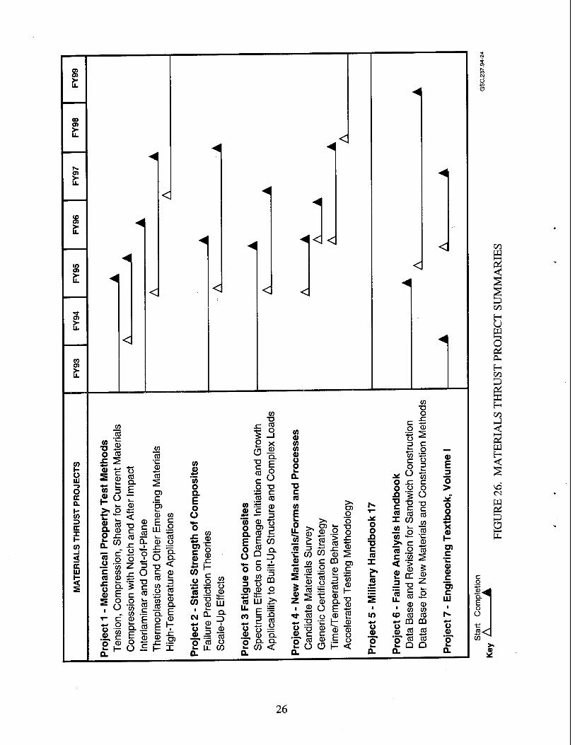
4.1 Mechanical Property Test Methods 18 4.2 Static Strength of Composites 19 4.3 Fatigue of Composites (Repeated-Load Spectrum Effects) 20 4.4 New Materials/Forms And Processes 20 4.5 Military Handbook 17 23 4.6 Failure Analysis Handbook 24 4.7 Engineering Textbook, Volume I 25 4.8 Thrust Summary 25
5. STRUCTURES 27
5.1 Structural Design Details 27 5.2 Delamination Evaluation Methods 29 5.3 Foreign Object Damage and Damage Containment 30 5.4 Bolted Joints in Composites 32 5.5 Fatigue of Bonded Joints 33 5.6 Probabilistic Methods 34 5.7 Engineering Textbook, Volume 2 35 5.8 Training 35 5.9 Thrust Summary 36
6. MANUFACTURING AND SUPPORT ABILITY 38
6.1 NDE of Advanced Materials and Bonded Joints 39 6.2 Quality Control of Manufacturing Processes 40 6.3 Repair Methodology 40 6.4 Paint Removal 41 6.5 Safety Inspector Handbook 41 6.6 Airworthiness Inspectors Handbook 42
iii
6.7 Thrust Summary 43
7. PRODUCTS 45
8. REFERENCES 46
IV

LIST OF ILLUSTRATIONS
Figure Page
1 Evolution of Advanced Materials 2 2 Advanced Material Application Requirements 3 3 Composites on Transport Aircraft 3 4 Estimated Price of Airframe Structures 4 5 Commercial Aircraft Components 5 6 Various Aircraft Components 6 7 Carbon Fiber Material Distribution 6 8 Boeing 777 Aircraft Composite Structure 8 9 Boeing 777 Aircraft Composite Fan Blade 8 10 V-22 Material Applications 9 11 Thrust Reverser Featuring New High Temperature Materials 10 12 Boeing Mach 2.4 Baseline Configuration 11 13 Structural Material Candidates and Projected Temperature Range for HSCT Application 11 14 Concept of Smart Structures System 12 15 Certification Pyramid 13 16 Advanced Materials Technology Flow Chart 14 17 Handbook Activities of AAMRDP Plan 15 18 Correspondence Table Between AAMRDP Programs and Research Project Initiatives 16 19 Advanced Materials/Structures Contract R&D Budgets 17 20 Test Methods for Shear Property 18 21 Triaxial Braid Pattern 21 22 Potential MMC Applications for High Speed Aircraft 21 23 MMC Applications for High Performance 22 24 Specific Stiffness of Aluminum Alloy 8009 and Conventional Aerospace Alloys 23 25 Components of Failure Analysis Handbook 24 26 Materials Thrust Project Summaries 26 27 Stiffener Termination Configurations 28 28 Transition from Concentrated Load Input to Basic Skin 28 29 A-Scan of Typical Fastener-Induced Delamination 29 30 Impact Damage in Composite Laminates 30 31 Appearance of Failed Pressurized Cylinders 31 32 Stiffener Lay-Up Changes Damage Path 32 33 Probabilistic Design 34 34 Reliability Requirements as a Function of Load Capability 35 35 Structures Thrust Project Summaries 37 36 Production Techniques for PMC Components 42 37 Manufacturing and Supportability Thrust Project Summaries 44
LIST OF ABBREVIATIONS AND SYMBOLS
AAMRDP AC ACES ACT AIA AIR APU ARALL ARPA ASTM ATA
Aircraft Advanced Materials Research and Development Program Advisory Circular Aircraft Command in Emergency Situations Advanced Composites Technology Aerospace Industries Association Aerospace Information Report Auxiliary power units Aluminum Reinforced with Layers of Glass or Aramid Fibers Advanced Research Projects Agency American Society of Testing Materials Air Transport Association
BMI Bismaleimides
C/C CACRC CIS CMC
Carbon/Carbon Commercial Aircraft Composite Repair Committee Commonwealth of Independent States Ceramic Matrix Composites
DFBW DoD
EPM
FAA FAR FCCSET FO
Digital fly-by-wire Department of Defense
Enabling Propulsion Materials Program
Federal Aviation Administration Federal Airworthiness Regulation Federal Coordinating Council for Science, Engineering and Technology Fiber Optic
GAA
HSCT
IATA
General Aviation Aircraft
High-Speed Civil Transport
International Air Transport Association
JAA JAR
Joint Airworthiness Authority Joint Airworthiness Requirement
MIL-HDBK MMC MSC
Military Handbook Metal Matrix Composites Materials Sciences Corporation
VI
NASA NAWCAD NDE NTSB
OEM
PABST PL PMB PMC
R&D RPI RTM
SAE
TQM
USAF
National Aeronautical Space Administration Naval Air Warfare Center, Aircraft Division Non-Destructive Evaluation National Transportation Safety Board
Original Equipment Manufacturer
Primary Adhesively Bonded Structures Public Law Plastic Media Blasting Polymeric Media Blasting
Research and Development Research Project Initiative Resin Transfer Molding
Society of Automotive Engineers
Total Quality Management
United States Air Force
Vll
EXECUTIVE SUMMARY
Advanced materials research has introduced a wide array of materials into civil aircraft. As advanced materials become increasingly complex, so have the issues related to their manufacturing, in-service usage, design, and analysis. The Federal Aviation Administration's (FAA) Certification and Flight Standards Services relies on advanced materials research to perform their role of assuring aircraft safety. This Aircraft Advanced Materials Research and Development Plan (AAMRDP) is designed to provide that research by developing data on materials being introduced into the design of current and future civil aircraft. These data form the basis for rule-making, advisory circulars, and training. The research proposed in the AAMRDP also fosters development of advanced materials and manufacturing to continue the United States' leading position in aviation in a way that does not compromise safety. To achieve these goals efficiently, and to avoid duplication of effort, the FAA will coordinate research with other government agencies.
The AAMRDP identifies technology issues that must be addressed to accomplish the FAA mission. The plan focuses on three technology thrusts: materials, structures, and manufacturing and supportability.
The goal of the materials thrust is to predict the response of a given material system to anticipated in- service chemical, thermal, and mechanical environments. The immediate need in this area is to concentrate on the fiber-reinforced polymer matrix components and their in-service derivatives and in existing production commitments. Long-term objectives include evaluation of newly developed materials as they enter production on new aircraft.
Projects in the structures thrust require evaluation of structural elements, subcomponents, and full-scale assemblies. Issues addressed in this plan include methodologies needed to evaluate the required strength, stiffness, durability, and damage tolerance of the airframe and/or engine structural parts to ensure safety and successful application in service.
The manufacturing and supportability thrust includes research that will lead to safe operation of the aircraft throughout its life. This is accomplished by developing inspection methods to find defects or anomalies in advanced materials structures. The FAA will closely follow advances in fabrication processes, tooling, processing science, and quality assurance and respond effectively when they appear in commercial certification programs and production commitments.
The FAA's advanced materials mission is mandated by Public Law (PL) 100-591 Aviation Safety Research Act of 1988 and House of Representatives Report 100-894. Under this legislation, the FAA has been charged to conduct or supervise research "to develop technologies and to conduct data analyses for predicting the effects of aircraft design, maintenance, testing, wear and fatigue on the life of aircraft and on air safety, to develop methods of analyzing and improving aircraft maintenance technology and practices (including nondestructive evaluation of aircraft structures ...)" The FAA is charged to take an active approach to research by anticipating the problems of future aircraft. Comprehensive long-term research is encouraged as well as addressing the immediate problems of the existing aircraft fleet.
The research performed under this plan falls under Goal Number 3 of the Department of Transportation (DOT) Strategic Plan established by the Secretary of Transportation. Goal Number 3 is to "Create a new alliance between the nation's transportation and technology industries to make them both more efficient
ix
and internationally competitive." The Strategic Plan elaborates upon Goal Number 3 by identifying key objectives and high priority activities in achieving it, i.e., establishing Goal Number 3.3: "Support the use of advanced materials in manufacturing and constructing transportation equipment and facilities."
Research performed in accordance with the AAMRDP will provide the basis for publishing and updating existing handbooks intended for engineers, inspectors, and repair technicians. The existing handbooks are Fiber Composites Analysis and Design, Vol. I and II, An Engineering Compendium on Manufacture and Repair of Fiber-Reinforced Components, and MIL-HDBK-17D, Polymer Matrix Composites. The latter is partially supported by the FAA. These handbooks contain information on the design, analysis, damage tolerance, inspection, and supportability of aircraft structure fabricated from composites. Activity in support of the existing Failure Analysis Handbook will provide additional, newer information for accident investigation authorities. The database of information and handbooks generated by the projects outlined in this program plan will furnish a vehicle for technology transfer from researchers to the customer base.
The research projects in this plan fulfill specific mission needs identified in Research Projects Initiatives (RPIs) developed by the sponsoring organization within the FAA. Projects are within the guidelines of the Aviation Safety Research Act of 1988 and fulfill assignation of sufficient effort to long-term research. The plan was reviewed by industry, academic personnel, and other government agencies to ensure responsiveness to industry needs.
1. INTRODUCTION.
This document represents the Aircraft Advanced Materials Research and Development Program (AAMRDP) Plan. This plan is structured to support the Federal Aviation Administration (FAA) Aircraft Certification and Flight Standards Services' role of assuring aircraft safety by providing data on materials being introduced into the design of current and future civil aircraft. The data will form the basis for rule-making, advisory circulars, and training. The research proposed in the AAMRDP will also foster development of advanced materials and manufacturing to continue the United States' leading position in aviation in a way that does not compromise safety. The AAMRDP supports the aircraft industry's use of advanced materials in the design of aircraft. Airline operators' fears of higher maintenance and training costs associated with structural innovations are addressed.
The scope of the AAMRDP plan is limited to structural airworthiness and propulsion applications. Research and development (R&D) activities using advanced materials for security (cargo container, armoring), occupant survivability (high energy absorption materials and seats), fire safety (fire resistant cabin materials), flight safety (lightning strike protection), and airport technologies (improved concrete) are covered in Aviation Security, Long-Range Aircraft Fire Safety, Aviation Safety, and Airport Technology Plans. Continual interaction with these programs will enhance shared technology developments.
The AAMRDP plan continues existing programs and starts new initiatives dictated by anticipated use of new materials, old materials in new construction forms, and new service applications. To maintain the currency of the AAMRDP, the plan will be updated periodically to reflect both new requirements and technologies.
The research projects in this plan fulfill specific mission needs identified in Research Projects Initiatives (RPIs) developed by sponsoring organizations within the FAA. Projects are within the guidelines of Aviation Safety Research Act of 1988 (Public Law [PL] 100-591) and devotes a sufficient effort to long- term research. The plan was reviewed by industry and academic personnel, and other government agencies to ensure responsiveness to industry needs. Individual elements of this plan are being coordinated with other government agencies, particularly the National Aeronautics and Space Administration (NASA) and the Department of Defense (DoD), to avoid duplication of effort and obtain maximum benefit through technology transfer between military and civil applications.
1.1 BACKGROUND.
To achieve higher performance and lower cost, commercial aircraft will increase their use of advanced materials. Application of polymeric composite materials to aerospace structures over the past 30 years is well documented. The higher specific strength and stiffness of reinforced composites versus metals and other attributes such as tailorability to load directionality, acoustic damping, and high fatigue endurance, make composites attractive for use in safety-of-flight structures. The weight savings realized from improved structural efficiency translate directly into increased payload, reduced acquisition and operating cost, and/or increased performance. Each pound of weight saved on a commercial aircraft is estimated to save $100 to $300 over the life of aircraft. This has led to large sections of transport airframes (entire empennages, major portions of wing structure) to be built from composites. The advantages of composites have been especially important to helicopters and business aircraft: new business aircraft have been built with all composite airframes and new helicopter rotor blades are
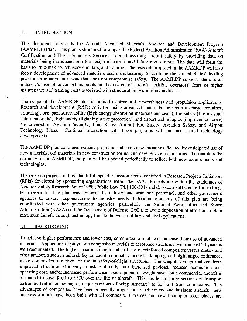
exclusively fabricated with composites or hybrid composite/metal combinations. The current fleet of small general aviation aircraft (GAA) have little or no composites. Thus the recent NASA GAA initiative is to redress this situation. In the future, higher temperature-capable polymeric composites, metal/matrix, and ceramic matrix composite materials will find extensive use in engines and high speed aircraft airframes such as High Speed Civil Transport (HSCT). Figure 1 shows the recent evolution of advanced materials schematically.
GSC.237.94-1
FIGURE 1. EVOLUTION OF ADVANCED MATERIALS
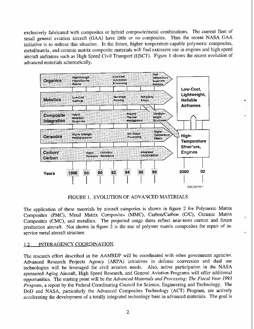
The application of these materials by aircraft categories is shown in figure 2 for Polymeric Matrix Composites (PMC), Metal Matrix Composites (MMC), Carbon/Carbon (C/C), Ceramic Matrix Composites (CMC), and metallics. The projected usage dates reflect near-term current and future production aircraft. Not shown in figure 2 is the use of polymer matrix composites for repair of in- service metal aircraft structure.
1.2 INTER AGENCY COORDINATION.
The research effort described in the AAMRDP will be coordinated with other government agencies. Advanced Research Projects Agency (ARPA) initiatives in defense conversion and dual use technologies will be leveraged for civil aviation needs. Also, active participation in the NASA sponsored Aging Aircraft, High Speed Research, and General Aviation Programs will offer additional opportunities. The starting point will be the Advanced Materials and Processing: The Fiscal Year 1993 Program, a report by the Federal Coordinating Council for Science, Engineering and Technology. The DoD and NASA, particularly the Advanced Composites Technology (ACT) Program, are actively accelerating the development of a totally integrated technology base in advanced materials. The goal is
APPLICATION CATEGORY
MATERIAL TYPE PROJECTED USAGE DATE
PMC | MMC | C/C | CMC | METALS 1990 | 1995 | 2000
Subsonic Transports
Supersonic Transports (HSCT)
Hypervelocity Vehicles
Helicopters
Business Aircraft
General Aviation Aircraft
Aircraft Engines
•• •
— • • * ••
— — — •• #9
M
—
—
A A A A
A A A A A A
A A A A
= Critical : Beneficial GSC.237.94-2
FIGURE 2. ADVANCED MATERIAL APPLICATION REQUIREMENTS
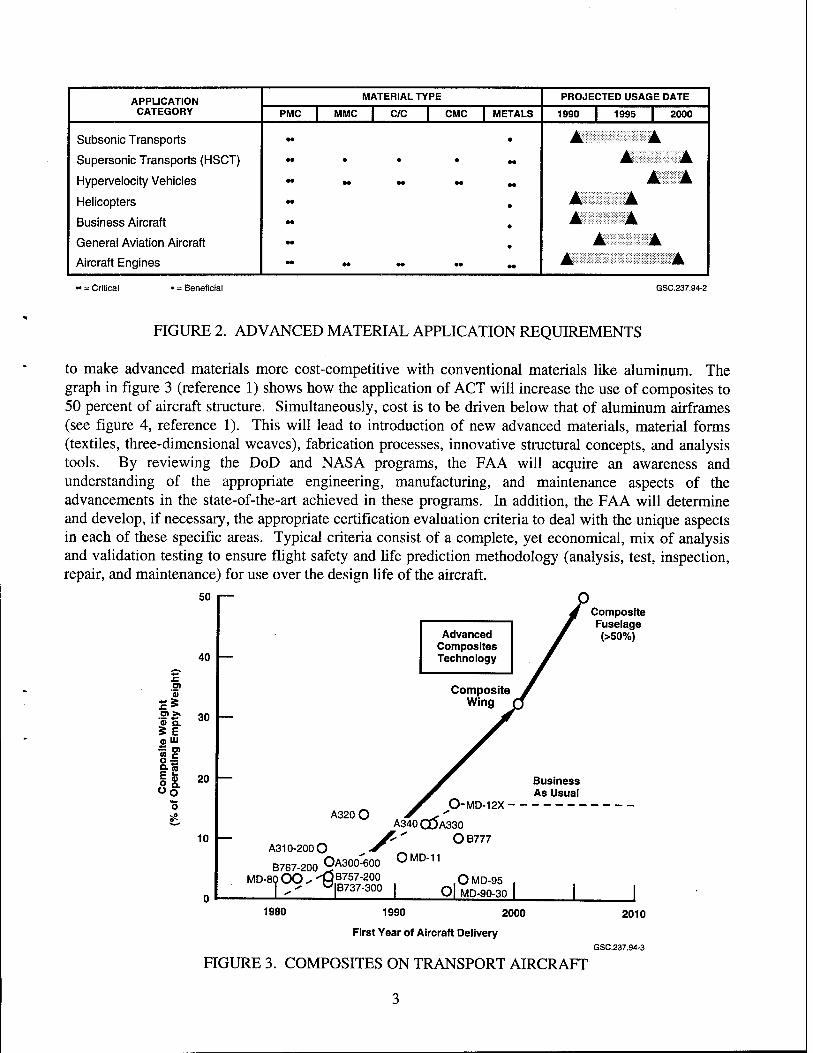
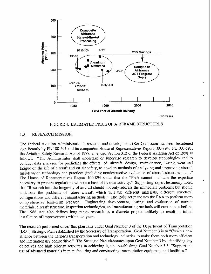
to make advanced materials more cost-competitive with conventional materials like aluminum. The graph in figure 3 (reference 1) shows how the application of ACT will increase the use of composites to 50 percent of aircraft structure. Simultaneously, cost is to be driven below that of aluminum airframes (see figure 4, reference 1). This will lead to introduction of new advanced materials, material forms (textiles, three-dimensional weaves), fabrication processes, innovative structural concepts, and analysis tools. By reviewing the DoD and NASA programs, the FAA will acquire an awareness and understanding of the appropriate engineering, manufacturing, and maintenance aspects of the advancements in the state-of-the-art achieved in these programs. In addition, the FAA will determine and develop, if necessary, the appropriate certification evaluation criteria to deal with the unique aspects in each of these specific areas. Typical criteria consist of a complete, yet economical, mix of analysis and validation testing to ensure flight safety and life prediction methodology (analysis, test, inspection, repair, and maintenance) for use over the design life of the aircraft.
50 Composite Fuselage (>50%)
03 0)
0) Q. S E O UJ
If
40
30
20
10
Advanced Composites Technology
Composite Wing
A320O 0-MD-12X ■
A340 Q5A330
^ S'" O B777 A310-200 O <r
OA300^600 OMD-11
Business As Usual
B767-200 ^ MD-8QOO^i3B757-200
I ^ °B737-300 OMD-95
Q| MD-90-30
1980 1990 2000
First Year of Aircraft Delivery
2010
GSC.237.94-3
FIGURE 3. COMPOSITES ON TRANSPORT AIRCRAFT
500
400
0) u
E£ 300
200
100 —
MD-80
B767-200 A300-600
B757-200
B747-400
1980 1990 2000
First Year of Aircraft Delivery
2010
GSC.237.94-4
FIGURE 4. ESTIMATED PRICE OF AIRFRAME STRUCTURES
1.3 RESEARCH MISSION.
The Federal Aviation Administration's research and development (R&D) mission has been broadened significantly by PL 100-591 and its companion House of Representatives Report 100-894. PL 100-591, the Aviation Safety Research Act of 1988, amended Section 312 of the Federal Aviation Act of 1958 as follows: "The Administrator shall undertake or supervise research to develop technologies and to conduct data analyses for predicting the effects of aircraft design, maintenance, testing, wear and fatigue on the life of aircraft and on air safety, to develop methods of analyzing and improving aircraft maintenance technology and practices (including nondestructive evaluation of aircraft structures The House of Representatives Report 100-894 states that the "FAA cannot maintain the expertise necessary to prepare regulations without a base of its own activity." Supporting expert testimony noted that "Research into the longevity of aircraft should not only address the immediate problems but should anticipate the problems of future aircraft which will use different materials, different structural configurations and different manufacturing methods." The 1988 act mandates the FAA to perform more comprehensive long-term research. Engineering development, testing, and evaluation of current materials, aircraft structure, inspection technologies, and manufacturing methods will continue as before. The 1988 Act also defines long range research as a discrete project unlikely to result in initial installation of improvements within ten years.
The research performed under this plan falls under Goal Number 3 of the Department of Transportation (DOT) Strategic Plan established by the Secretary of Transportation. Goal Number 3 is to "Create a new alliance between the nation's transportation and technology industries to make them both more efficient and internationally competitive." The Strategic Plan elaborates upon Goal Number 3 by identifying key objectives and high priority activities in achieving it, i.e., establishing Goal Number 3.3: "Support the use of advanced materials in manufacturing and constructing transportation equipment and facilities."

In compliance with the 1988 Act, DOT Strategic Plan, and identified industry and user needs, the FAA is expanding its research efforts in advanced materials. The FAA research plan is well coordinated with other government agencies (ARPA, NASA, DoD) to ensure a leveraged product. This coordination will ensure that the needed design, manufacture, inspection, and maintenance certification procedures for aircraft structures will be available to support technology advances such as new material forms, low-cost manufacturing processes, and smart structures.
2. PROGRAM DEVELOPMENT.
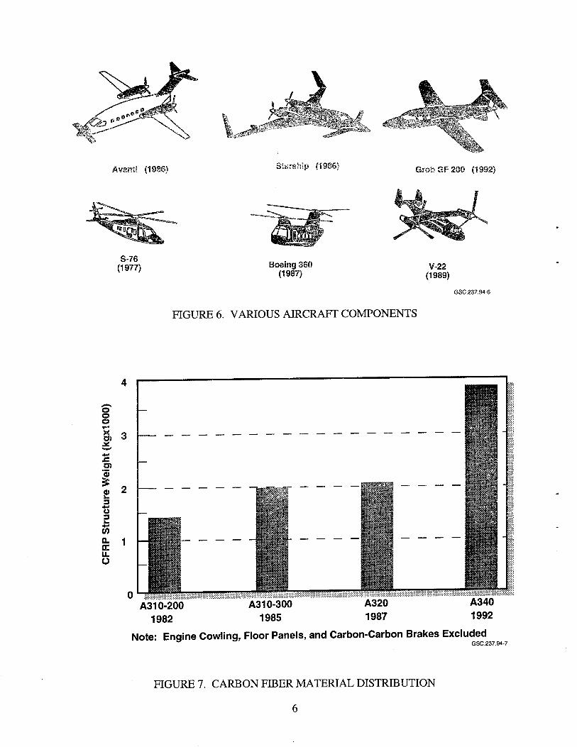
This plan has been developed to meet the needs identified by the FAA, aircraft manufacturers, and airlines. It closely follows the current and forecast advanced materials applications to airframes and engines. The composite materials used during the last 20 years consisted of carbon, fiberglass, and aramid fibers impregnated with thermoset epoxy resins. On large transport aircraft, composite materials were used initially to manufacture control surfaces followed by engine cowlings and empennages (see figure 5). The application of these materials was even greater in business aircraft and helicopters, where entire airframes were constructed from these materials (see figure 6). The parts shown in figures 5 and 6 were fabricated by either vacuum bagging with autoclave cure or wet lay-up with vacuum pressure cure. The future of general aviation aircraft is dependent on fabricating airframes out of composites that are affordable. Hence, materials research must also explore new methods of manufacture that are cost- effective.
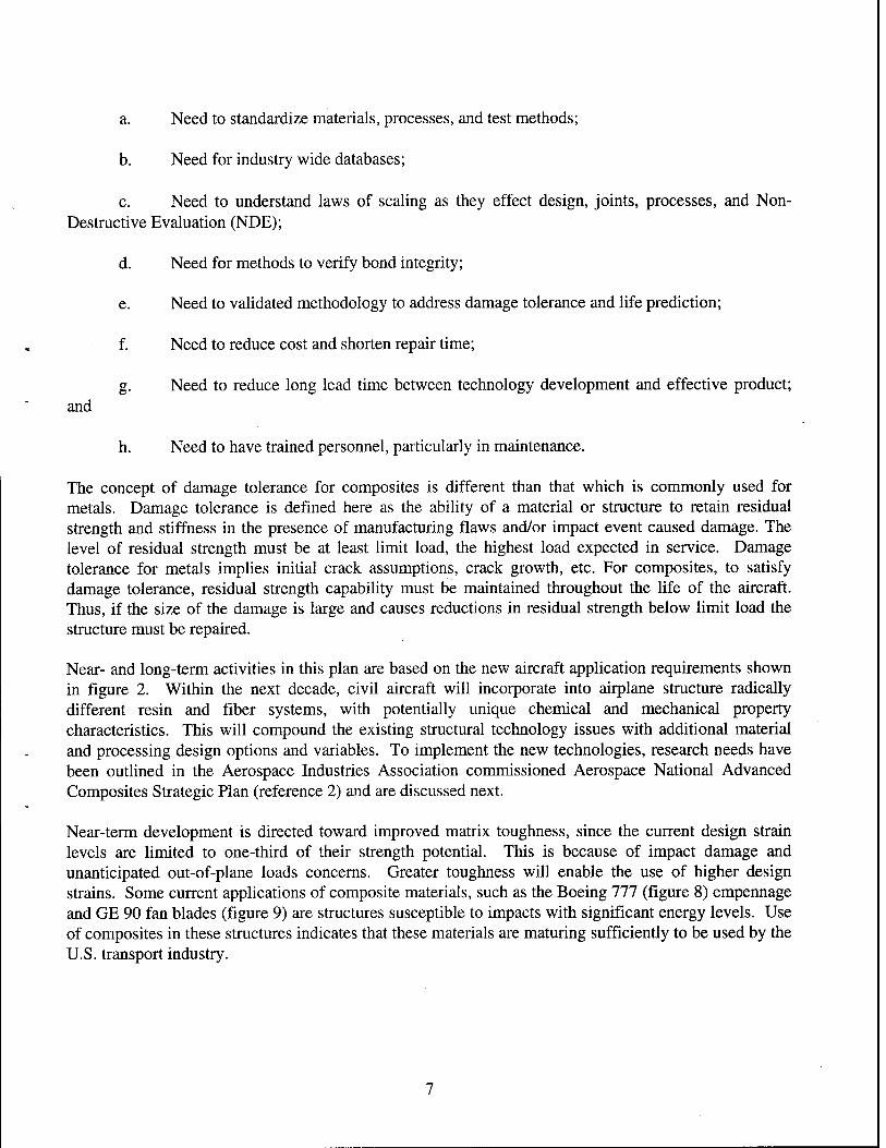
The use of composite materials in civil transport aircraft structure has increased markedly, as illustrated by the Airbus products shown in figure 7. However, there are still technical areas where lack of knowledge has resulted in composite structure that may be too conservatively designed and have poor supportability features. Filling the knowledge gaps will spur greater use of composites for applications such as transport aircraft wings and fuselages. These gaps, recast as needs, are being addressed in on- going projects and are enumerated below.
B-737 Spoilers (1973) Stabilizer (1984)
A320
ATR 72 (1988)
"Composite Parts in Black
A340 A330
(1991) (1993) B-777 (1994)
GSC.237.94-5
FIGURE 5. COMMERCIAL AIRCRAFT COMPONENTS
5
m.
Avant! (1086)
S-76 (1977)
Starship (1986) Grob GF 200 (1992)
Boeing 360 (1987)
FIGURE 6. VARIOUS AIRCRAFT COMPONENTS
V-22 (1989)
GSC.237.94-6
o © o T™
3 ^ ■*■** +■• JC 0) 0)
£ 0) 2 ^ 3 *J Ü 3 ^ +■• w Q. 1 K o
A310-200 A310-300 A320 A340 1982 1985 1987 1992
Note: Engine Cowling, Floor Panels, and Carbon-Carbon Brakes Excluded GSC.237.94-7
FIGURE 7. CARBON FIBER MATERIAL DISTRIBUTION
6
a. Need to standardize materials, processes, and test methods;
b. Need for industry wide databases;
c. Need to understand laws of scaling as they effect design, joints, processes, and Non- Destructive Evaluation (NDE);
d. Need for methods to verify bond integrity;
e. Need to validated methodology to address damage tolerance and life prediction;
f. Need to reduce cost and shorten repair time;
g. Need to reduce long lead time between technology development and effective product; and
Need to have trained personnel, particularly in maintenance.
The concept of damage tolerance for composites is different than that which is commonly used for metals. Damage tolerance is defined here as the ability of a material or structure to retain residual strength and stiffness in the presence of manufacturing flaws and/or impact event caused damage. The level of residual strength must be at least limit load, the highest load expected in service. Damage tolerance for metals implies initial crack assumptions, crack growth, etc. For composites, to satisfy damage tolerance, residual strength capability must be maintained throughout the life of the aircraft. Thus, if the size of the damage is large and causes reductions in residual strength below limit load the structure must be repaired.
Near- and long-term activities in this plan are based on the new aircraft application requirements shown in figure 2. Within the next decade, civil aircraft will incorporate into airplane structure radically different resin and fiber systems, with potentially unique chemical and mechanical property characteristics. This will compound the existing structural technology issues with additional material and processing design options and variables. To implement the new technologies, research needs have been outlined in the Aerospace Industries Association commissioned Aerospace National Advanced Composites Strategic Plan (reference 2) and are discussed next.
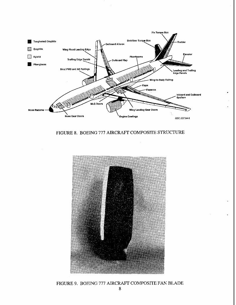
Near-term development is directed toward improved matrix toughness, since the current design strain levels are limited to one-third of their strength potential. This is because of impact damage and unanticipated out-of-plane loads concerns. Greater toughness will enable the use of higher design strains. Some current applications of composite materials, such as the Boeing 777 (figure 8) empennage and GE 90 fan blades (figure 9) are structures susceptible to impacts with significant energy levels. Use of composites in these structures indicates that these materials are maturing sufficiently to be used by the U.S. transport industry.
Fin Torque Box
I Toughened Graphite
IB Graphite wing Fixed Leading Edge
pi Hybrid
9 Flberglasss
Nose Radome
Trailing Edge Panels
Strut FWD and Aft Fairings Leading and Trailing Edge Panels
Nose Gear Doors
Wing Landing Gear Doors
Engine Cowlings
Inboard and Outboard Spoilers
GSC.237.94-8
FIGURE 8. BOEING 777 AIRCRAFT COMPOSITE STRUCTURE
FIGURE 9. BOEING 777 AIRCRAFT COMPOSITE FAN BLADE 8
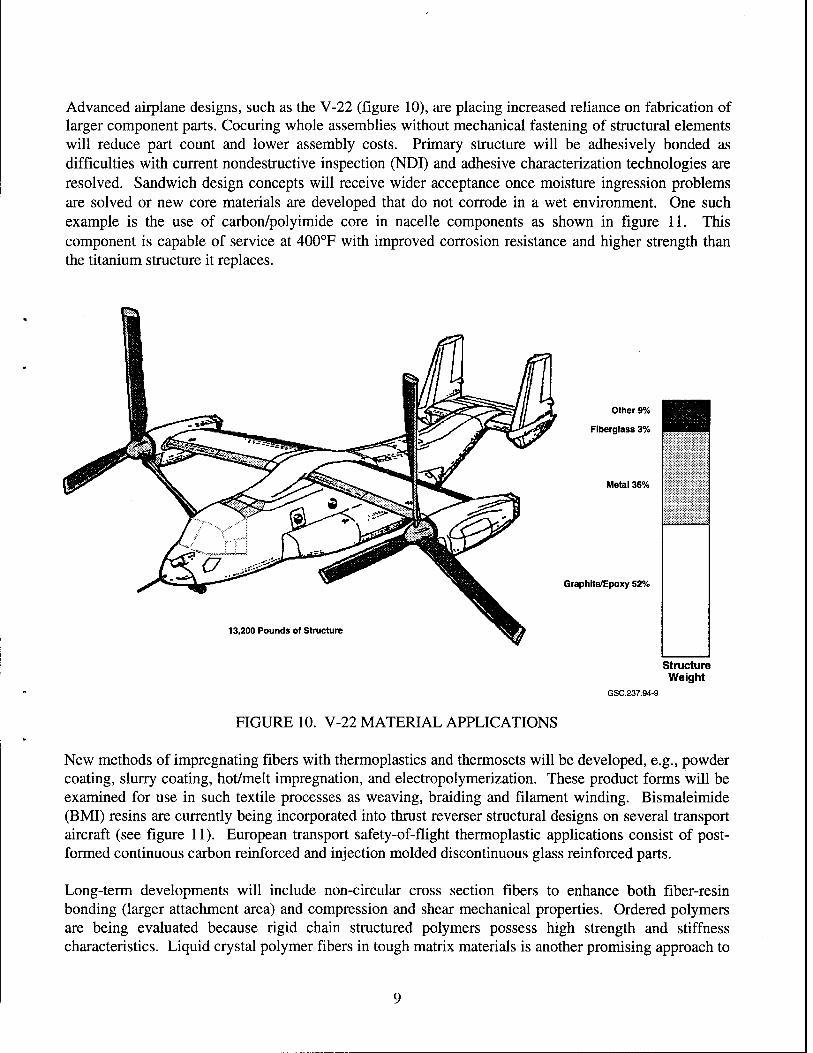
Advanced airplane designs, such as the V-22 (figure 10), are placing increased reliance on fabrication of larger component parts. Cocuring whole assemblies without mechanical fastening of structural elements will reduce part count and lower assembly costs. Primary structure will be adhesively bonded as difficulties with current nondestructive inspection (NDI) and adhesive characterization technologies are resolved. Sandwich design concepts will receive wider acceptance once moisture ingression problems are solved or new core materials are developed that do not corrode in a wet environment. One such example is the use of carbon/polyimide core in nacelle components as shown in figure 11. This component is capable of service at 400°F with improved corrosion resistance and higher strength than the titanium structure it replaces.
Other 9%
Fiberglass 3%
Metal 36%
Graphite/Epoxy 52%
13,200 Pounds of Structure
Structure Weight
GSC.237.94-9
FIGURE 10. V-22 MATERIAL APPLICATIONS
New methods of impregnating fibers with thermoplastics and thermosets will be developed, e.g., powder coating, slurry coating, hot/melt impregnation, and electropolymerization. These product forms will be examined for use in such textile processes as weaving, braiding and filament winding. Bismaleimide (BMI) resins are currently being incorporated into thrust reverser structural designs on several transport aircraft (see figure 11). European transport safety-of-flight thermoplastic applications consist of post- formed continuous carbon reinforced and injection molded discontinuous glass reinforced parts.
Long-term developments will include non-circular cross section fibers to enhance both fiber-resin bonding (larger attachment area) and compression and shear mechanical properties. Ordered polymers are being evaluated because rigid chain structured polymers possess high strength and stiffness characteristics. Liquid crystal polymer fibers in tough matrix materials is another promising approach to
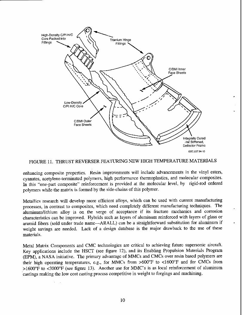
High-Density C/PI H/C Core Packed into Fittings
C/BMI Inner Face Sheets
Low-Density C/PI H/C Core
C/BMI Outer Face Sheets
Integrally Cured Hat Stiffened,
Deflector Frame
GSC.237.94-10
FIGURE 11. THRUST REVERSER FEATURING NEW HIGH TEMPERATURE MATERIALS
enhancing composite properties. Resin improvements will include advancements in the vinyl esters, cyanates, acetylene-terminated polymers, high performance thermoplastics, and molecular composites. In this "one-part composite" reinforcement is provided at the molecular level, by rigid-rod ordered polymers while the matrix is formed by the side-chains of this polymer.
Metallics research will develop more efficient alloys, which can be used with current manufacturing processes, in contrast to composites, which need completely different manufacturing techniques. The aluminum/lithium alloy is on the verge of acceptance if its fracture mechanics and corrosion characteristics can be improved. Hybrids such as layers of aluminum reinforced with layers of glass or aramid fibers (sold under trade name—ARALL) can be a straightforward substitution for aluminum if weight savings are needed. Lack of a design database is the major drawback to the use of these materials.
Metal Matrix Components and CMC technologies are critical to achieving future supersonic aircraft. Key applications include the HSCT (see figure 12), and its Enabling Propulsion Materials Program (EPM), a NASA initiative. The primary advantage of MMCs and CMCs over resin based polymers are their high operating temperatures, e.g., for MMCs from >600°F to <1600°F and for CMCs from >1600°F to <3000°F (see figure 13). Another use for MMCs is as local reinforcement of aluminum castings making the low cost casting process competitive in weight to forgings and machining.
10

GSC.237.94-12
FIGURE 12. BOEING MACH 2.4 BASELINE CONFIGURATION
Polymer Matrix Composites •Epoxy • Polyetheretherketone • Toughened BMI ■ Thermoplastic polymide • Polymide • Fluorinated Polymide
LEGEND I I Year 2000 Availability
Year 2015 Availability
Metals • Aluminum • Aluminum Lithium • Titanium • Intermetallics '//////////////////////;;/S/)/J>///;/////////////A
Metal Matrix Composites • Aluminum Matrix ■ Titanium Matrix ■ Intermetallic Matrix Ceramic Matrix Composite I%%@@£%M
I 300 600 900 1,200
°F
1,500 1,800 2,100 2,400 2,700 3,000
GSC.237.94-13
FIGURE 13. STRUCTURAL MATERIAL CANDIDATES AND PROJECTED TEMPERATURE RANGE FOR HSCT APPLICATION
Titanium matrix MMC materials, and intermetallic compounds based on titanium aluminides are being developed for these high performance engine and high speed airframe applications. The continuous reinforcements include silica carbons and alumina. These airframe applications include wing and empennage torque-box structure, landing gear struts, fittings, etc. High performance engine applications include fan duct, fan rotor and stator, compressor disks, exhaust nozzle, etc.
Specific aeropropulsion needs for small engines can be met by ceramics. These include regenerators, recuperators, combustors, turbine blades/bladed discs, vanes, seals, tail cone, nozzle, and in large engines: high pressure compressor components, combustors, turbine blades/bladed discs, vanes, seals, tail cone, nozzle, and bearings. Ceramic matrix materials now being developed include glass (e.g.,
11
borosilicate, lithium aluminosilicate), oxides (e.g., alumina, cordierite), nitrides (e.g., silicon nitride, aluminum nitride, boron nitride), and carbides (e.g., alpha-silicon carbide, beta-silicon carbide, titanium carbide). The reinforcements include alumina, mullite, and silica carbon in particular, whisker, and monofilament forms.
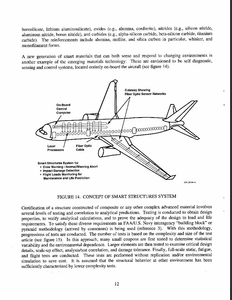
A new generation of smart materials that can both sense and respond to changing environments is another example of the emerging materials technology: These are envisioned to be self diagnostic, sensing and control systems, located entirely on-board the aircraft (see figure 14).
On-Board Central Computer
Local Processors
Smart Structures System for • Crew Warning - Normal/Warning Abort • Impact Damage Detection • Flight Loads Monitoring for
Maintenance and Life Prediction GSC .237.94-14
FIGURE 14. CONCEPT OF SMART STRUCTURES SYSTEM
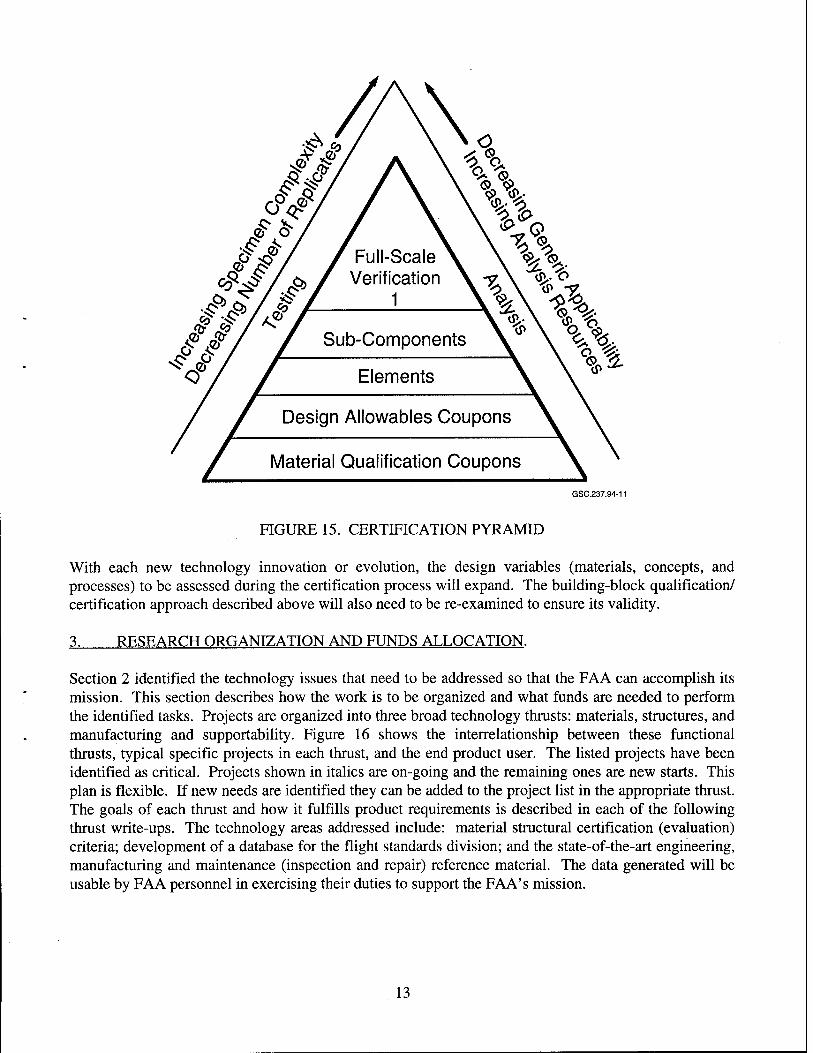
Certification of a structure constructed of composite or any other complex advanced material involves several levels of testing and correlation to analytical predictions. Testing is conducted to obtain design properties, to verify analytical calculations, and to prove the adequacy of the design to load and life requirements. To satisfy these diverse requirements an FAA/U.S. Navy interagency "building block" or pyramid methodology (arrived by consensus) is being used (reference 3). With this methodology, progressions of tests are conducted. The number of tests is based on the complexity and size of the test article (see figure 15). In this approach, many small coupons are first tested to determine statistical variability and the environmental dependence. Larger elements are then tested to examine critical design details, scale-up effect, analysis/test correlation, and damage tolerance. Finally, full-scale static, fatigue, and flight tests are conducted. These tests are performed without replication and/or environmental simulation to save cost. It is assumed that the structural behavior at other environment has been sufficiently characterized by lower complexity tests.
12
GSC.237.94-11
FIGURE 15. CERTIFICATION PYRAMID
With each new technology innovation or evolution, the design variables (materials, concepts, and processes) to be assessed during the certification process will expand. The building-block qualification/ certification approach described above will also need to be re-examined to ensure its validity.
3. RESEARCH ORGANIZATION AND FUNDS ALLOCATION.
Section 2 identified the technology issues that need to be addressed so that the FAA can accomplish its mission. This section describes how the work is to be organized and what funds are needed to perform the identified tasks. Projects are organized into three broad technology thrusts: materials, structures, and manufacturing and supportability. Figure 16 shows the interrelationship between these functional thrusts, typical specific projects in each thrust, and the end product user. The listed projects have been identified as critical. Projects shown in italics are on-going and the remaining ones are new starts. This plan is flexible. If new needs are identified they can be added to the project list in the appropriate thrust. The goals of each thrust and how it fulfills product requirements is described in each of the following thrust write-ups. The technology areas addressed include: material structural certification (evaluation) criteria; development of a database for the flight standards division; and the state-of-the-art engineering, manufacturing and maintenance (inspection and repair) reference material. The data generated will be usable by FAA personnel in exercising their duties to support the FAA's mission.
13
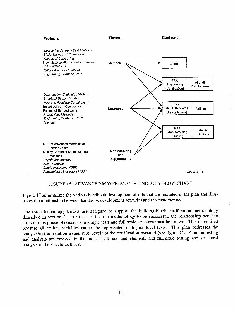
Projects Thrust Customer
Mechanical Property Test Methods Static Strength of Composites Fatigue of Composites New Materials/Forms and Processes MIL-HDBK- 17 Failure Analysis Handbook Engineering Textbook, Vol I
Delamination Evaluation Method Structural Design Details FOD and Fuselage Containment Bolted Joints in Composites Fatigue of Bonded Joints Probabilistic Methods Engineering Textbook, Vol II Training
NDE of Advanced Materials and Bonded Joints
Quality Control of Manufacturing Processes
Repair Methodology Paint Removal Safety Inspectors HDBK Airworthiness Inspectors HDBK
Materials
Structures
Manufacturing and
Supportability
NTSB
FAA , Engineering i
(Certification) j
Aircraft Manufactures
FAA Flight Standards (Airworthiness)
Airlines
FAA , Manufacturing i
(Quality) '
Repair Stations
GSC.237.94-15
FIGURE 16. ADVANCED MATERIALS TECHNOLOGY FLOW CHART
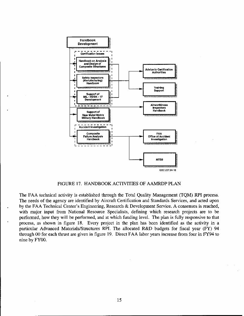
Figure 17 summarizes the various handbook development efforts that are included in the plan and illus- trates the relationship between handbook development activities and the customer needs.
The three technology thrusts are designed to support the building-block certification methodology described in section 2. For the certification methodology to be successful, the relationship between structural response obtained from simple tests and full-scale structure must be known. This is required because all critical variables cannot be represented in higher level tests. This plan addresses the analysis/test correlation issues at all levels of the certification pyramid (see figure 15). Coupon testing and analysis are covered in the materials thrust, and elements and full-scale testing and structural analysis in the structures thrust.
14
Handbook Development
Certification Issues
Handbook on Analysis and Design of
Composite Structures
Safety inspectors (Manufacturing)
Handbook ■-■■•■■^^^^^^
Support of MIL-HDBK-17
Development
Support of New Metal Matrix Military Handbook
Accident Investigation
Composite Failure Analysis
Handbook
Advice to Certification Authorities
'
Training Support
Airworthiness Inspectors Handbook
FAA Office of Accident
Investigation
NTSB
GSC.237.94-16
FIGURE 17. HANDBOOK ACTIVITIES OF AAMRDP PLAN
The FAA technical activity is established through the Total Quality Management (TQM) RPI process. The needs of the agency are identified by Aircraft Certification and Standards Services, and acted upon by the FAA Technical Center's Engineering, Research & Development Service. A consensus is reached, with major input from National Resource Specialists, defining which research projects are to be performed, how they will be performed, and at which funding level. The plan is fully responsive to that process, as shown in figure 18. Every project in the plan has been identified as the activity in a particular Advanced Materials/Structures RPI. The allocated R&D budgets for fiscal year (FY) 94 through 00 for each thrust are given in figure 19. Direct FAA labor years increase from four in FY94 to nine by FY00.
15

"tf r-
t/1 cn l-i <U & a (N 3 r- z cn
<l> > ,—i
cd r- ■*-* cn C
HH
■4—1
o vn 'o1 cn (H
OH 43 o "fr <u rn c/l ü U Vi <L> cn 1 S£3 o cn 3 tH
-t—»
00 Vi <—H
"r3 MD • ~H
>-l C)
<U 133
s T3 U O
o
e cd >
T3 < ON
«n cn
X
X
X X
XXX
1/3
o ja
%ä V <D H
OH o l-H
OH
13 o
•t-H s cd ,3 U
1/3 o
t o U «4-H o J3
o o
•§ c cd
■3 O
3 U M 0) <+H <L> ►H O -ö +-» ^ cd
73 U 5
4-» *i-H S 3 a I oo üH Z
' cd 3 < D l-H
3
PQ Q
dl
o > M O O
t/j X
3
0) 3 bß
cd 3
X
X X
X
X X
X X
X X
X X X X
VI
o •B
o S 3 o '£ 'cd >
W 3 O
'3 3
13 Q
3 U B «3
.s s r^ £ "V\ £ "cd S •4-» O
QU
3 5P DO Ja
'35 ü
!■§ P cd
pQ S o 00 p-i
6 O na ~ O
^«
T3 J3 <u -Sri
S S 9 o
003
(ÖPHÖH
o >
O O
X <D
H bß 3
• i-H i-l Ü <u 3
öß 3
CO ■*-»
3 vt
O 00 Hl t/3
3 CU
<% ■§
■a *u 13 g SS T3 «4-H 0 o O r-H
§ a I § < u
o ^
o o
3 cd
O O
€ 3 cd K
1/3 >-. o o &, 1/1 3
1—1
1/3
Ü
öß 3 tt
«IS Q 3
o
Q. 3 <U cd & 0H
0 .5* .3 " > T-i -3 eä +-! *J
Q U _ OH 3 «3 .*H
>. o
cd •■-!
00
8 1—1 P-,
16
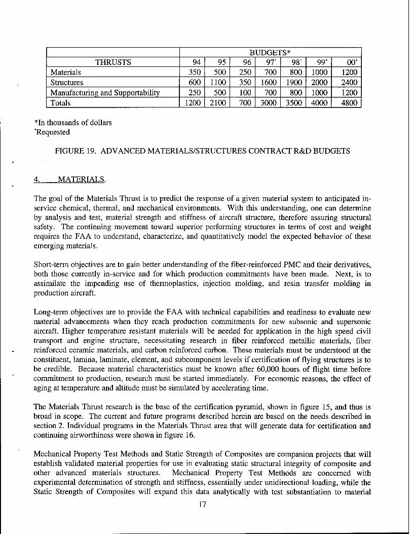
BUDGE! ̂ S* THRUSTS 94 95 96 97+ 98+ 99+ 00+
Materials 350 500 250 700 800 1000 1200 Structures 600 1100 350 1600 1900 2000 2400 Manufacturing and Supportability 250 500 100 700 800 1000 1200 Totals 1200 2100 700 3000 3500 4000 4800
*In thousands of dollars ^Requested
FIGURE 19. ADVANCED MATERIALS/STRUCTURES CONTRACT R&D BUDGETS
4. MATERIALS.
The goal of the Materials Thrust is to predict the response of a given material system to anticipated in- service chemical, thermal, and mechanical environments. With this understanding, one can determine by analysis and test, material strength and stiffness of aircraft structure, therefore assuring structural safety. The continuing movement toward superior performing structures in terms of cost and weight requires the FAA to understand, characterize, and quantitatively model the expected behavior of these emerging materials.
Short-term objectives are to gain better understanding of the fiber-reinforced PMC and their derivatives, both those currently in-service and for which production commitments have been made. Next, is to assimilate the impending use of thermoplastics, injection molding, and resin transfer molding in production aircraft.
Long-term objectives are to provide the FAA with technical capabilities and readiness to evaluate new material advancements when they reach production commitments for new subsonic and supersonic aircraft. Higher temperature resistant materials will be needed for application in the high speed civil transport and engine structure, necessitating research in fiber reinforced metallic materials, fiber reinforced ceramic materials, and carbon reinforced carbon. These materials must be understood at the constituent, lamina, laminate, element, and subcomponent levels if certification of flying structures is to be credible. Because material characteristics must be known after 60,000 hours of flight time before commitment to production, research must be started immediately. For economic reasons, the effect of aging at temperature and altitude must be simulated by accelerating time.
The Materials Thrust research is the base of the certification pyramid, shown in figure 15, and thus is broad in scope. The current and future programs described herein are based on the needs described in section 2. Individual programs in the Materials Thrust area that will generate data for certification and continuing airworthiness were shown in figure 16.
Mechanical Property Test Methods and Static Strength of Composites are companion projects that will establish validated material properties for use in evaluating static structural integrity of composite and other advanced materials structures. Mechanical Property Test Methods are concerned with experimental determination of strength and stiffness, essentially under unidirectional loading, while the Static Strength of Composites will expand this data analytically with test substantiation to material
17
response under generalized loading. Fatigue of Composites (Repeated-Loaded Spectrum Effects) is a project similar to the two efforts described above, which provides material characterization data under repeated loads simulating aircraft operations. The properties that will be obtained are in terms of life (number of flight hours of safe operation) rather than strength.
The New Materials/Forms and Processes Project parallels of the three activities described above for application to near-term aircraft, with similar work in future materials and their application for planned aircraft with new requirements of higher temperatures and longevity. Included in this project are characterization of materials using newer manufacturing processes such as Resin Transfer Molding (RTM) of three-dimensional weaves and stitching. These processes will improve out-of-plane strength yet retain the potential to reduce the cost of producing composite structure.
Three handbook activities pertinent to the topics of this thrust are Military Handbook 17 (MIL-HDBK- 17), Failure Analysis Handbook, and the Fiber Composites Analysis and Design, Volume I. Figure 17 shows the relationship of these handbooks to other organizations and activities within this plan.
4.1 MECHANICAL PROPERTY TEST METHODS.
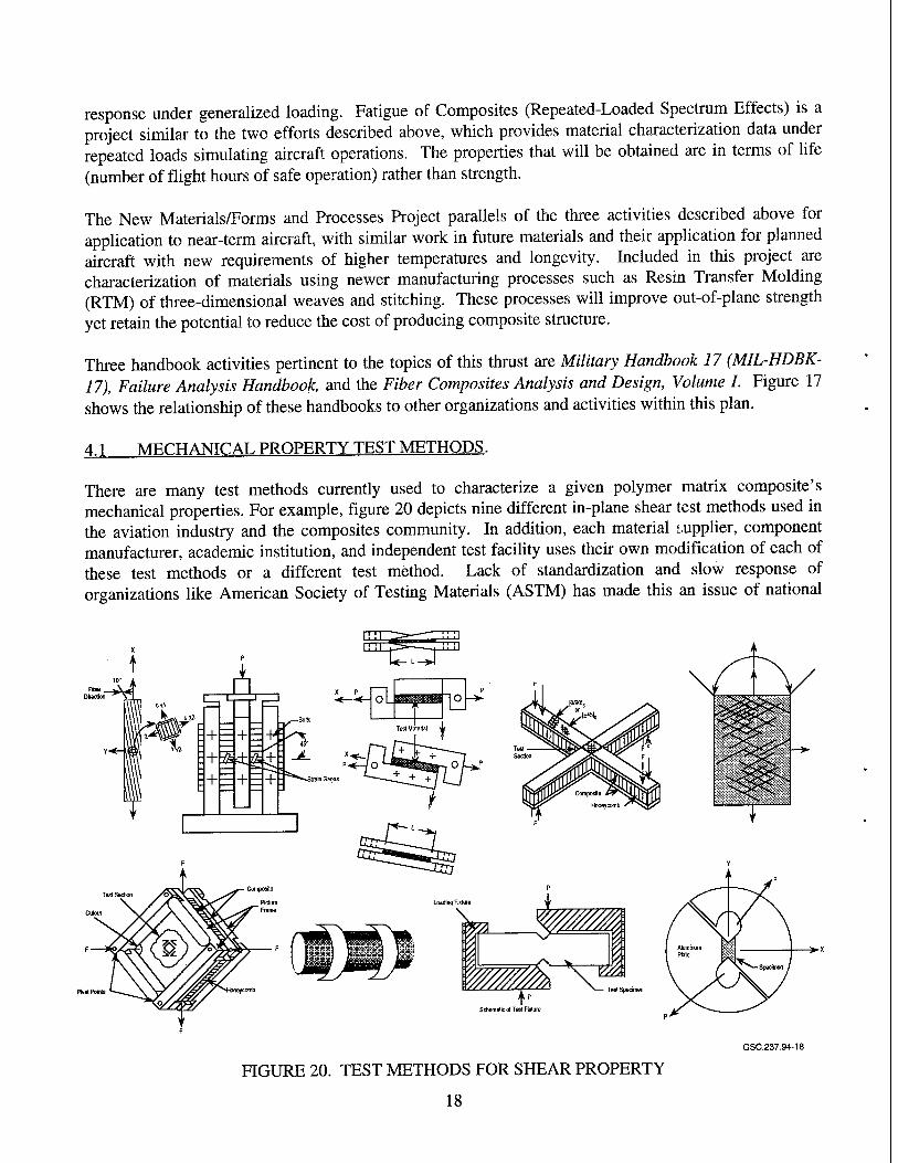
There are many test methods currently used to characterize a given polymer matrix composite's mechanical properties. For example, figure 20 depicts nine different in-plane shear test methods used in the aviation industry and the composites community. In addition, each material supplier, component manufacturer, academic institution, and independent test facility uses their own modification of each of these test methods or a different test method. Lack of standardization and slow response of organizations like American Society of Testing Materials (ASTM) has made this an issue of national
^P—P
Schemata of TesI Fixture
GSC.237.94-18
FIGURE 20. TEST METHODS FOR SHEAR PROPERTY
18
concern. Since the FAA is routinely asked by aviation manufacturers to approve composite material allowables based on these test methods, a research effort has been started to determine which, of the many material property test methods, identifies/quantifies the desired failure modes most effectively. The results of this project will provide both the FAA and the aircraft industry the necessary knowledge to make informative judgments on the validity of a manufacturer's mechanical material property data. The information developed will be submitted to the joint government and industry committee developing MIL-HDBK-17 for standardization, and will serve as a guide for future generation materials.
The first phase of this project, which is underway now, consists of evaluating the in-plane and transverse shear, compression, and tension mechanical material property test methods currently used to characterize PMCs. This effort will be expanded to include evaluation of test specimens, test fixture configurations, and testing procedures for lamina/laminates for interlaminar fracture toughness, and open hole compression and tension. The results will narrow the number of acceptable test methods. The applica- bility of the selected test methods to other carbon composites e.g., high temperature thermoset materials (BMIs, polyimides) and thermoplastics, and glass and aramid composites will be addressed.
Test methods for MMCs and CMCs require more development before they can be standardized because these materials are not yet mature. A comprehensive and commonly accessible material property database does not exist for continuous or discontinuous reinforced MMC and even less is available on CMC. To develop the databases required to ease the introduction of MMC and CMC into engines and high speed civil transport, the project will develop accurate and reliable standards for test specimen design, test methods, and data reporting formats. Complicating this task is the higher thermal test environment requiring non-contact strain measurements and thermal management.
4.2 STATIC STRENGTH OF COMPOSITES.
Analysis to predict composite failure has been successful in some point-design cases. However, there is no general agreement on the failure criterion for the basic element of the composite: the unidirectional ply. This technology gap needs to be filled. The lack of an agreed upon criterion affects predictive capability at all levels of the building block—laminates, joints, design detail, and full-scale components. There is also a lack of dedicated testing, particularly for combined load cases, to determine the required material constants and to validate the theories. Analytical tools are needed to relate (scale-up) information from one step of the building block to the next. The analysis must be supported by testing since the developed analysis will be semi-empirical. In summary, a systematic predictive methodology must be developed to reduce costly test requirements for future aircraft. While the focus should be on PMCs, parallel smaller efforts should be initiated for MMCs and CMCs.
Many composite material failure theories exist, ranging from those that assume failure will occur when a single stress or strain component reaches its ultimate value irrespective of the values of the other stress/strain components, to those represented by a quadratic polynomial in stress or strain. The former disregards the combined effects of stresses/strains on failure and the latter ignores the fact that fiber- reinforced composite is a combination of two materials: fiber and matrix. For distinctly heterogeneous materials, separate and physically more realistic failure criteria for the fibers, matrix, and possibly the interface are necessary. These failure criteria, used in analysis of safety-of-flight structure, are routinely presented to the FAA for approval. Each has to be judged on individual merit based on the particular validation data. The data displayed usually show good curve fit to the test specimen data (reference 4). The lack of universal acceptance of one theory results in a prolonged certification process.
19
Research has been initiated to evaluate the various failure criteria, conduct the tests necessary to validate all four quadrants (tension-tension, compression-tension, tension-compression, compression-compres- sion) for which these criteria have expressions, and modify the criteria as necessary. This effort will use the test methods selected from the Mechanical Property Test Methods project described previously.
4.3 FATIGUE OF COMPOSITES (REPEATED-LOAD SPECTRUM EFFECTS).
Since the mid-1960s, DoD and NASA sponsored activities focused on gaining insight into the integrity of aircraft structures constructed of composite materials. As a result, much is known about the phenomenological process of how damage initiates, propagates, and causes final failure. However, little is known about how this process is affected by loads encountered in-flight and during landing. Furthermore, although the final failure can be predicted, the residual strength during the damage accumulation period has not been related to fatigue damage with any degree of success. Therefore, questions relating to remaining life and load carrying capability have not been resolved.
The FAA recently initiated an experimental research project to investigate the effect of load history on the lifetime of aircraft composite structures and to determine if the existing damage tolerance validation approach is appropriate. For metals, fatigue load test spectrums have been established which simulate real-time load cycle damage but at a much reduced testing time. The objective of this project is to develop similar testing capability for composites. Main components of spectrum generation such as truncation, clipping, sequencing, and test frequency will be studied in terms of their effect on fatigue damage and residual strength of composite. Current research focuses on the response of Hercules AS4/3501-6. A large database is associated with this commonly used carbon/epoxy material. A strong tie-in between critical damage and practical NDE will be pursued so that continuing airworthiness issues can be resolved. The information developed can be used immediately in ongoing certification programs. However, the long-term goal is to develop a fatigue damage rule that could predict composite material structural performance under spectrum loading. Such a rule is available for metals, but it is not applicable to composites. The methodology will be generic so that it can be applied to built-up aircraft structure subjected to three-dimensional loads. Once developed, this information will be incorporated into the FAA's composite material advisory circular and used in certification programs.
Test data will also be generated for the newer toughened epoxies, high temperature polymers, and thermoplastics. The data will be used to adapt the previously developed model to these materials. Some modification of the damage accumulation model may be necessary since there is evidence that these materials respond differently from those of present generation carbon/epoxies. While the focus of research will be on fiber reinforced polymers, parallel smaller efforts will be initiated for MMCs and CMCs.
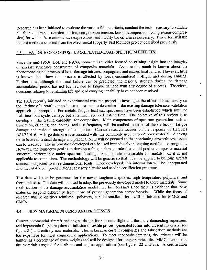
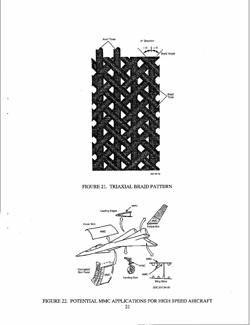
4.4 NEW MATERIALS/FORMS AND PROCESSES.
Current commercial aircraft and engine design for subsonic flight and the more demanding supersonic and hypersonic flights requires an infusion of textile process generated forms into present materials (see figure 21) and entirely new materials. This is because current composites and fabrication methods are too expensive for most commercial applications. To meet economic demands, the airframe will be lighter (as a percentage of gross weight) and will be designed for longer service life. MMCs are one of the materials targeted for airframe and engine applications (see figures 22 and 23). A certification
20
Axial Tows 0° Direction
>C^ ^Braid Angle
FIGURE 21. TRIAXIAL BRAID PATTERN
Leading Edges
MMC- ; Landing Gear n f\ f\ 0
Wing Skins
GSC.237.94-20
FIGURE 22. POTENTIAL MMC APPLICATIONS FOR HIGH SPEED AIRCRAFT 21

Fan Duct MMC
Compressor MMC Disks
Fan Rotor and Stator MMC
LP Shaft Steel and MMC
Exhaust Nozzle MMC
GSC.237.94-21
FIGURE 23. MMC APPLICATIONS FOR HIGH PERFORMANCE
strategy must be developed for these new materials and forms, particularly for the new requirements of elevated temperature and long-term exposure. This will include susceptibility to oxidation and temperature cycling. The combination of high temperature and long-term exposure may lead to certification areas where the material's mechanical properties are time dependent.
A survey of industry and NASA is planned to establish likely materials and forms, processing techniques, aircraft types, and times of introduction. With this information, a plan identifying development areas with timescales will be formulated for each material. Materials that will be studied include: BMIs, polyimides, aluminum lithium, high temperature aluminum alloys, MMCs, and CMCs. As the number of new materials and their variations escalate, a certification strategy must be developed that will be applicable across diverse materials and could be implemented with minimum elapsed time but with assured structural integrity.
Currently, there is no known procedure to apply the building-block approach to certification of structure manufactured by new fabrication processes. The basic unit of material that would be equivalent to a lamina in a standard tape lay-up is difficult to define, particularly for the RTM process with three- dimensional preform. Stitching poses a similar problem. Two approaches to this problem will be investigated. One approach is to predict the behavior of the structure using individual fiber and matrix properties. This will require development and validation of sophisticated analytical models. The other approach requires testing of representative, relatively large portions or elements made from repeating units which form a given structure. It will be advantageous to keep this unit cell as small as possible to have generic applicability and also reduce cost of testing.
22
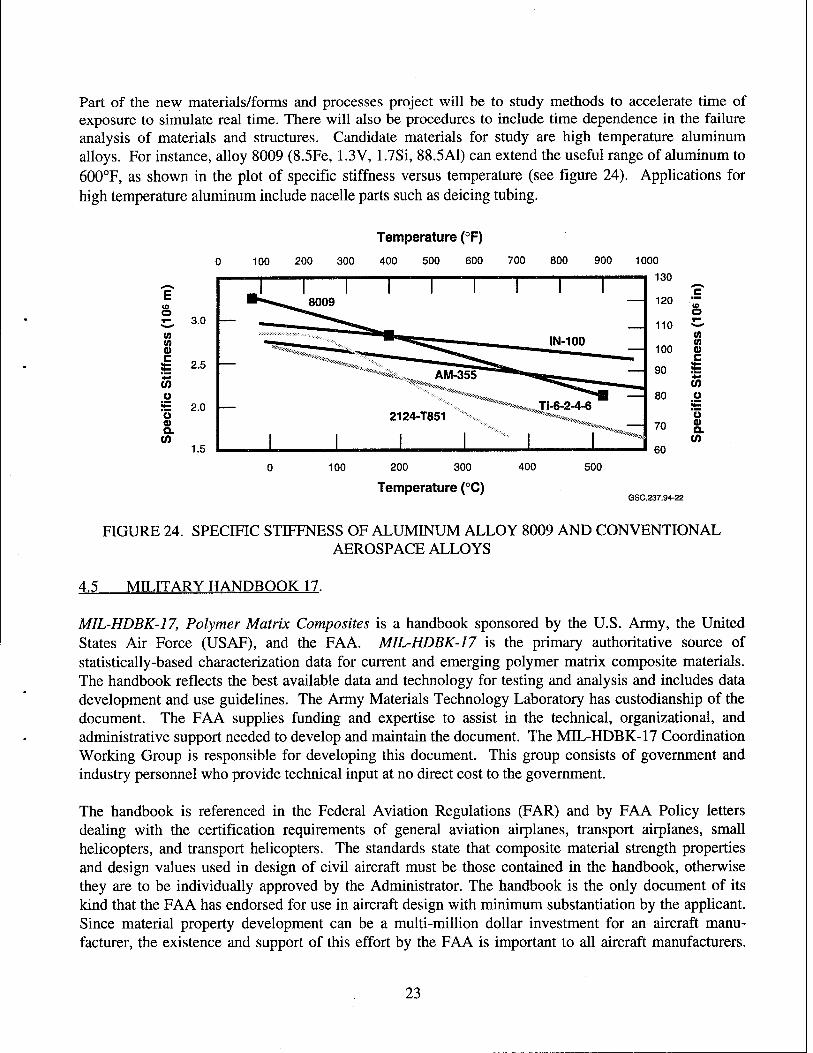
Part of the new materials/forms and processes project will be to study methods to accelerate time of exposure to simulate real time. There will also be procedures to include time dependence in the failure analysis of materials and structures. Candidate materials for study are high temperature aluminum alloys. For instance, alloy 8009 (8.5Fe, 1.3V, 1.7Si, 88.5A1) can extend the useful range of aluminum to 600°F, as shown in the plot of specific stiffness versus temperature (see figure 24). Applications for high temperature aluminum include nacelle parts such as deicing tubing.
Temperature (°F)
400 500 600 700 800 900
E CO O T- 3.0
CO (0 (D c
CO Ü
2.5
S= 2.0 u 0) Q. CO
1.5
100 200 300
Temperature (°C)
400 500
c CD o (0 (0 CO c ™ CO u o a a.
GSC.237.94-22
FIGURE 24. SPECIFIC STIFFNESS OF ALUMINUM ALLOY 8009 AND CONVENTIONAL AEROSPACE ALLOYS
4.5 MILITARY HANDBOOK 17.
MIL-HDBK-17, Polymer Matrix Composites is a handbook sponsored by the U.S. Army, the United States Air Force (USAF), and the FAA. MIL-HDBK-17 is the primary authoritative source of statistically-based characterization data for current and emerging polymer matrix composite materials. The handbook reflects the best available data and technology for testing and analysis and includes data development and use guidelines. The Army Materials Technology Laboratory has custodianship of the document. The FAA supplies funding and expertise to assist in the technical, organizational, and administrative support needed to develop and maintain the document. The MEL-HDBK-17 Coordination Working Group is responsible for developing this document. This group consists of government and industry personnel who provide technical input at no direct cost to the government.
The handbook is referenced in the Federal Aviation Regulations (FAR) and by FAA Policy letters dealing with the certification requirements of general aviation airplanes, transport airplanes, small helicopters, and transport helicopters. The standards state that composite material strength properties and design values used in design of civil aircraft must be those contained in the handbook, otherwise they are to be individually approved by the Administrator. The handbook is the only document of its kind that the FAA has endorsed for use in aircraft design with minimum substantiation by the applicant. Since material property development can be a multi-million dollar investment for an aircraft manu- facturer, the existence and support of this effort by the FAA is important to all aircraft manufacturers.
23

By supporting this effort, the FAA eliminates duplication of effort for each design and supports aviation at the level that needs the FAA's help the most; the small aircraft manufacturer.
Support for development and maintenance of this handbook will continue through research on issues identified by the MIL-HDBK-17 Coordination Group. Research will be conducted both at the FAA Technical Center and outside of the FAA.
4.6 FAILURE ANALYSTS HANDBOOK.
An interim Failure Analysis Handbook for composite material safety-of-flight structural applications was published in February 1992. The handbook was jointly sponsored by the FAA and USAF to provide the FAA, the National Transportation Safety Board (NTSB), USAF accident investigators, and industry structural engineers with information necessary to determine the probable cause of composite material structural failures. Failure analysis procedures are described in detail and many material systems are characterized. Figure 25 shows the organization of the handbook.
GSC.237.94-23
FIGURE 25. COMPONENTS OF FAILURE ANALYSIS HANDBOOK
While the first phase of handbook development is complete, much remains to be accomplished. Many material systems that have been and are being certified by the FAA are not included in the handbook and should be characterized now. Configuration dependent failure modes must also be addressed. These
24
include sandwich construction with honeycomb or foam and attachments. The FAA/USAF team intends to continue updating this handbook for future accident investigations.
4.7 ENGINEERING TEXTBOOK. VOLUME I.
Fiber Composite Analysis and Design, Volume I Composite Materials and Laminates, is the basic text of an out-of-agency analytical course taught to FAA engineers. This FAA sponsored engineering textbook includes such topics as micromechanics, lamination theory, laminate mechanical/thermal/moisture behavioral effects, and is highly regarded throughout academia.
Regular updates to this textbook are planned to keep it current with evolving technology. The FAA recently began a revision of this text to reflect technology advances made since its publication in 1985. Topics about MMCs and CMCs will be included in this revision.
4.8 THRUST SUMMARY.
Projects in the Materials Thrust are summarized in figure 26 together with their periods of performance.
25
O)
00 O)
O)
(O O)
in O)
at
w a>
(/) 1- ü UJ -s O DC Q.
H (0 D DC X I- <n < DC UJ
< S
<d
<j <l <1
<]
_co eg
O (0 £^ 2 0 *- fc » Ü " I—
s «
ü CO Q.
E
0
I §
_C0
CD
CO
C
« o C CO (Q 0
0 2
E o Ü
o 1
^ 3 c O
i TJ C
c CO o w c
1- c *- o 8 S
s I Q. JO
Ü S
& 0 co p c lS -2 bU ^_,
>- CO 0 Ü
K ^ ■o < C 0 CO -
Ü CO
'«0 © « °- Q. C O o> E *7 1- r;
V) ©
'to o a E o u o r- cn £ a) g>'o
w c ooiS a u 0 ♦1 s t w ^ S
*- 0 1 O != 0 .£.= "CO O CO Ü > u- w a.
CD TJ c CO
CO TJ CO o _1
X 0 Q.
E o
_ Ü O TJ •J C CO CO
MS 0) 0 c c: £Z — 3 u» a) t3 O 5> 3 £ EtO c CO
Q o u
Q. ID
0 0 = o ._ S> i2 m n> 0 o
« LU ^ U. CO
E 3
_0 0
XJ CO Ü
_ Q. Ö" a. a. jc co <
,<
<4<<
<
<
<
(0 0 Cfl (0 0 O O
■a c <a (0
E ■_ o
UL
ca
0
3 ■c CO
« CO
ü » ■ a>
*t co *- 5 O -D 0) C
"2cj a.
>. O
5^ O 0 O o
W ffl S
.2 0 c co ü 3 w
co -© ^ ® -n Ü E S Ü © 2
■ch 0) ©00 C r ü 0 C o O i- <
o o .a TJ C n X > co
m
Ü 0 o o.
co T3 O
c £ o a>
•■^ S o "^ 3 c
■t .2 S o o E
*o « O x: c O u o ^J > Ü
II" xc55 2 5£? CA
0 s o (5 c «I
2 x ©
,00 1 CO CO
CO CO CO *- DQ CO
0 iS iS ■5* co co 2 Q Q a.
0 E 3 o >
o o Si 4-» X 0 I- O) c 'iZ 0 0 c "5) c
UJ
o 0 'o a.
CN
O
c o
ex. E o Ü
s<
26

5. STRUCTURES.
The Structures Thrust consists of projects that evaluate structural elements and subcomponents, since small coupons are of little use to determine structural integrity and durability of joints and assemblies. Furthermore, it has been demonstrated that damage tolerance can be reliably established only by analysis and test of full-scale structure. Therefore, the structures thrust will address procedures to evaluate the required strength, stiffness, and residual strength after fatigue and damage of the airframe to ensure safety and successful applications in service. The resolution of these issues directly benefit (see figure 16) engineering for certification (modification of AC20-107A, Certification of Composites) operations for continued airworthiness and manufacturing for inspection guidance.
The Structures Thrust deals with structural elements, subcomponents, and full-scale assemblies. It addresses the middle and top portions of the certification pyramid (see figure 15). Since the polymeric composites are more mature than other advanced materials, early activity in this Thrust is in aircraft structures made of thermoset and thermoplastic resins with carbon fibers.
The Structures Thrust consists of eight projects. Structural Design Details, Delamination Evaluation Methods, Foreign Object Damage (FOD), and Fuselage Damage Containment are concerned with delaminations, the most endemic problem with composite structures. The Structural Delamination Evaluation Methodology will develop analytical or semi-empirical procedures for initiation and growth potential for a given delamination size. The developed methodology will then be coupled with Structural Design Details and Foreign Object Damage and Damage Containment projects. Together they will determine damage prone locations and stress states; critical load levels for damage growth, either stable or unstable; and remaining life and residual strength.
The Probabilistic Methods Project has been formulated in response to the Original Equipment Manufacturers (OEM) introduction of statistical methods to establish airframe integrity. Reliability of the component is calculated at some FAA/industry predetermined level in contrast to the current deterministic methods of calculating safety margins. The FA A must feel confident with this method- ology to ensure safety of aircraft.
Aircraft composite structures are sensitive to joint failure. Bolted Joints in Composites and Fatigue of Bonded Joints are planned to address repeated load issues that have not yet been satisfactorily resolved. An accurate model will be developed to predict useful life of both bolted and bonded joints.
5.1 STRUCTURAL DESIGN DETAILS.
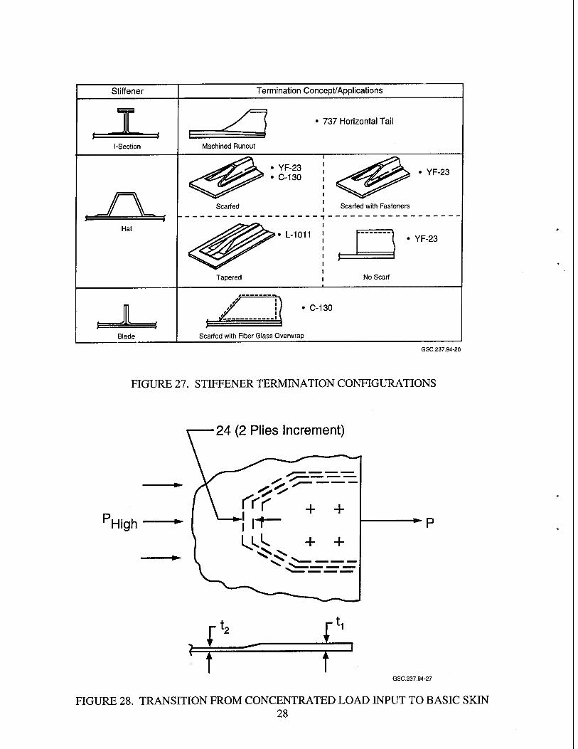
The FAA has initiated a study under an interagency agreement with NASA as part of their ACT program, to determine the fatigue scatter of composite material structural design details, such as stiffener runouts (see figure 27). Use of this information in certification validations will result in more realistic and meaningful repeated-load demonstrations. Analytical modeling of this structural detail will be performed to enable extension to similar failure modes but different geometries. The results for stiffener runouts will be extended to a systematic review of other design details, such as ply drop-offs by which thickness changes in composites are accomplished (see figure 28), and other details under complex state of loading. All of these details give rise to significant through-the-thickness stresses. This research will
27
Stiffener Termination Concept/Applications
^
737 Horizontal Tail
l-Section Machined Runout
r\ • YF-23 • C-130
Scarfed
Hat • L-1011
Tapered
• YF-23
Scarfed with Fasteners
YF-23
No Scarf
J C-130
Blade Scarfed with Fiber Glass Overwrap
GSC.237.94-26
FIGURE 27. STIFFENER TERMINATION CONFIGURATIONS
24 (2 Plies Increment)
High
I" II T T
GSC.237.94-27
FIGURE 28. TRANSITION FROM CONCENTRATED LOAD INPUT TO BASIC SKIN 28
identify the design and life drivers for certification purposes. The materials to be studied will include various classes of composite materials currently in production and those intended for future use. The stress analysis capability to be developed will be used directly in the fracture analysis for delamination initiation and growth.
5.2 DELAMINATION EVALUATION METHODS.
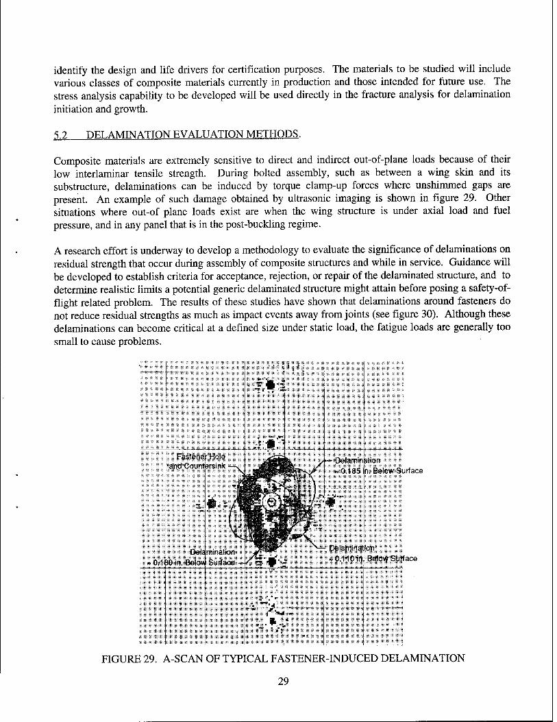
Composite materials are extremely sensitive to direct and indirect out-of-plane loads because of their low interlaminar tensile strength. During bolted assembly, such as between a wing skin and its substructure, delaminations can be induced by torque clamp-up forces where unshimmed gaps are present. An example of such damage obtained by ultrasonic imaging is shown in figure 29. Other situations where out-of plane loads exist are when the wing structure is under axial load and fuel pressure, and in any panel that is in the post-buckling regime.
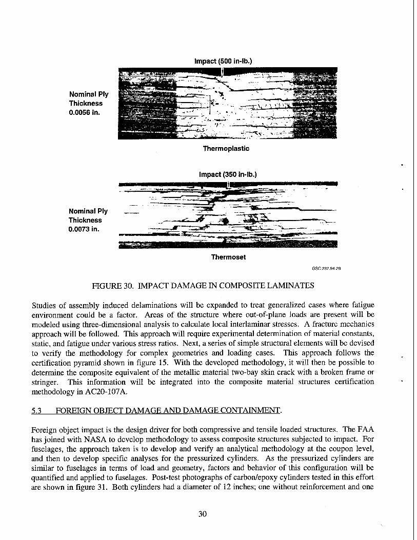
A research effort is underway to develop a methodology to evaluate the significance of delaminations on residual strength that occur during assembly of composite structures and while in service. Guidance will be developed to establish criteria for acceptance, rejection, or repair of the delaminated structure, and to determine realistic limits a potential generic delaminated structure might attain before posing a safety-of- flight related problem. The results of these studies have shown that delaminations around fasteners do not reduce residual strengths as much as impact events away from joints (see figure 30). Although these delaminations can become critical at a defined size under static load, the fatigue loads are generally too small to cause problems.
lion Below Surface
ßllÖVPfSiiface
FIGURE 29. A-SCAN OF TYPICAL FASTENER-INDUCED DELAMINATION
29
Impact (500 in-lb.)
Nominal Ply Thickness 0.0056 in.
Thermoplastic
Impact (350 in-lb.)
Nominal Ply Thickness 0.0073 in.
Thermoset GSC.237.94-29
FIGURE 30. IMPACT DAMAGE IN COMPOSITE LAMINATES
Studies of assembly induced delaminations will be expanded to treat generalized cases where fatigue environment could be a factor. Areas of the structure where out-of-plane loads are present will be modeled using three-dimensional analysis to calculate local interlaminar stresses. A fracture mechanics approach will be followed. This approach will require experimental determination of material constants, static, and fatigue under various stress ratios. Next, a series of simple structural elements will be devised to verify the methodology for complex geometries and loading cases. This approach follows the certification pyramid shown in figure 15. With the developed methodology, it will then be possible to determine the composite equivalent of the metallic material two-bay skin crack with a broken frame or stringer. This information will be integrated into the composite material structures certification methodology in AC20-107A.
5.3 FOREIGN OBJECT DAMAGE AND DAMAGE CONTAINMENT.
Foreign object impact is the design driver for both compressive and tensile loaded structures. The FAA has joined with NASA to develop methodology to assess composite structures subjected to impact. For fuselages, the approach taken is to develop and verify an analytical methodology at the coupon level, and then to develop specific analyses for the pressurized cylinders. As the pressurized cylinders are similar to fuselages in terms of load and geometry, factors and behavior of this configuration will be quantified and applied to fuselages. Post-test photographs of carbon/epoxy cylinders tested in this effort are shown in figure 31. Both cylinders had a diameter of 12 inches; one without reinforcement and one
30
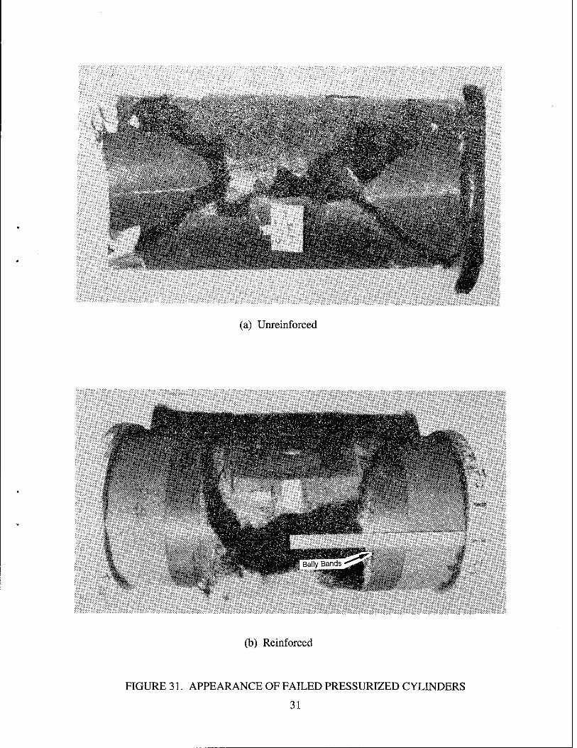
BäHs*?*«*;.*-*'' ..'f'Äj; .i-jVfcfe*•^Si.**-1* •>•:g»cWiw .- fieP
(a) Unreinforced
(b) Reinforced
FIGURE 31. APPEARANCE OF FAILED PRESSURIZED CYLINDERS
31
with belly bands and simple reinforcements. It is clear from figure 31 that belly bands can change the direction of tears and thus contain the damage. This test work will be continued with larger diameters to demonstrate influence of curvature and fuselage configurations with stringer and frames. Other parameters to be investigated are different materials, automated manufacturing methods and more realistic damage states. This effort will culminate in a full-scale test. The objective of testing various configurations is for analysis validation and scale-up law creation to reduce test requirements in the certification process.
Current efforts include developing an understanding of the damage resistance parameters for various structural configurations to perform structural scaling. Obtaining a good prediction of the three- dimensional damage state will provide the necessary input for damage tolerance assessments.
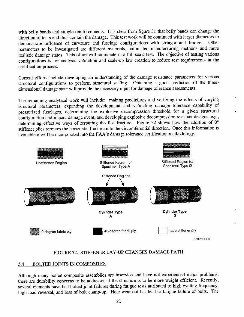
The remaining analytical work will include: making predictions and verifying the effects of varying structural parameters, expanding the development and validating damage tolerance capability of pressurized fuselages, determining the explosive decompression threshold for a given structural configuration and impact damage event, and developing explosive decompression resistant designs, e.g., determining effective ways of rerouting the fast fracture. Figure 32 shows how the addition of 0° stiffener plies reroutes the horizontal fracture into the circumferential direction. Once this information is available it will be incorporated into the FAA's damage tolerance certification methodology.
Unstiffened Region Stiffened Region for Specimen Type A
Stiffened Regions
/ \
Cylinder Type A
Stiffened Region for Specimen Type D
Cylinder Type D
0-degree fabric ply 45-degree fabric ply tape stiffener ply
GSC.237.94-30
FIGURE 32. STIFFENER LAY-UP CHANGES DAMAGE PATH
5.4 BOLTED JOINTS IN COMPOSITES.
Although many bolted composite assemblies are inservice and have not experienced major problems, there are durability concerns to be addressed if the structure is to be more weight efficient. Recently, several elements have had bolted joint failures during fatigue tests attributed to high cycling frequency, high load reversal, and loss of bolt clamp-up. Hole wear-out has lead to fatigue failure of bolts. The
32
objectives of this project are to gain better understanding of the behavior of bolted joints for static and fatigue loading, and to provide design data for MIL-HDBK-17.
The problem will be approached by first defining the bolted joint behavior under static load, as an isolated bolt, and in a bolt pattern. This will consist of three-dimensional analysis for bearing stress distribution and improved estimates of joint flexibilities as a function of ply orientation and percentage of plies in each direction. The static analysis will then be applied to repeated load situations. Issues to be addressed for both constant amplitude and spectrum fatigue are fastener spacing and types, including effect of clamp-up and bushings. A concurrent test program for the semi-empirical analysis model development and validation will be performed. The amount of testing depends on a review of government/industry data. New data generated will use MEL-HDBK-17 recommended test methods so that it can be included in the handbook adding value to it, particularly for small aircraft manufacturers.
5.5 FATIGUE OF BONDED JOINTS.
In principle, adhesive joints are structurally more efficient than mechanically fastened joints. Bonded joints eliminate hole drilling and fasteners resulting in aircraft structure that is not marred by inherent discontinuities. However, analysis and fabrication of bonded joints has to be improved to satisfy airframe manufactures and FAA.
Two schools of thought have evolved on structural requirements for adhesive joints. For several years there has been considerable activity in the use of fracture mechanics concepts. Joint life is considered to be controlled by the growth of crack-like flaws in the adhesive layer. Useful life is then predicted using linear elastic fracture mechanics with crack growth data obtained by appropriate experiments.
A second approach evolved from the U.S. Air Force's Primary Adhesively Bonded Structures (PABST) program of the mid-1970s. This approach asserts that in sound adhesive joint design, out-of-plane stresses can be eliminated by correct tapering of the joint elements. This assumption requires ductile adhesives and results in analysis where only shear stresses are considered. The durability of the joint is believed to depend on limiting the bond length over which ductile behavior occurs at maximum operating loads. Results of the PABST program suggested that if the region of elastic response of the adhesive is long enough to ensure that the minimum shear stress is less than 10 percent of the yield strength of adhesive, infinite lifetime of the joint under cyclic loads can be expected. However, these "rules of thumb" are arbitrary, probably very conservative, and may apply only to specific adhesives and environmental conditions.
Issues that need to be addressed concerning bonded joints include:
a. To what extent can out-of-plane (peel) stresses be eliminated in typical aircraft components, and what design situations exist where out-of-plane stresses cannot be eliminated by permissible geometrical design options?
b. If out-of-plane stresses cannot be avoided, is it necessary to incorporate a fracture mechanics failure criterion involving calculation of strain energy release rates in the adhesive with assumed initial flaws of appropriate length?
33
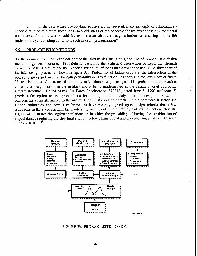
c. In the case where out-of-plane stresses are not present, is the principle of establishing a specific ratio of minimum shear stress to yield stress of the adhesive for the worst-case environmental condition such as hot-wet or cold-dry exposure an adequate design criterion for ensuring infinite life under slow cyclic loading conditions such as cabin pressurization?
5.6 PROBABILISTIC METHODS.
As the demand for more efficient composite aircraft designs grows, the use of probabilistic design methodology will increase. Probabilistic design is the statistical interaction between the strength variability of the structure and the expected variability of loads that stress the structure. A flow chart of the total design process is shown in figure 33. Probability of failure occurs at the intersection of the operating stress and material strength probability density functions, as shown in the lower box of figure 33, and is expressed in terms of reliability rather than strength margin. The probabilistic approach is currently a design option in the military and is being implemented in the design of civil composite aircraft structure. United States Air Force Specification 87221A, dated June 8, 1990 (reference 5) provides the option to use probabilistic load-strength failure analysis in the design of structural components as an alternative to the use of deterministic design criteria. In the commercial sector, the French authorities and Airbus (reference 6) have recently agreed upon design criteria that allow reductions in the static strength factor-of-safety in cases of high reliability and low inspection intervals. Figure 34 illustrates the log/linear relationship in which the probability of having the combination of impact damage reducing the structural strength below ultimate load and encountering a load of the same intensity is 10 E .
Design Process
> Loads > Geometry ■ Sizing > Material
Allowables
Operating Stress
^Ä?Kö M|
Material Production
• Acceptance Testing
• Incoming Material Strength
Bucking Adjustments
Operating Stress
Manufacturing Process
• Hole Defects • Laminate Defects • Impact Defects • Material Wavlness • Out of Tolerance
I '"
Material Strength
Adjusted Material Strength
1 ■
Operations
• Foreign Object Damage
• Bird Strike • Temperature • Moisture
Probability of
Failure
GSC.237.94-31
FIGURE 33. PROBABILISTIC DESIGN
34
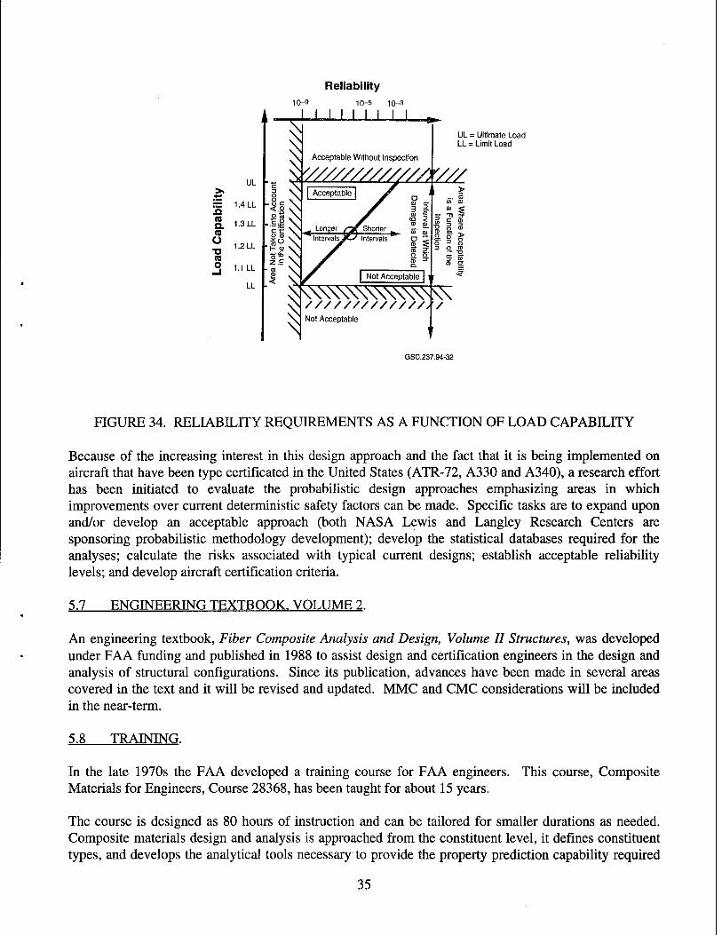
Reliability 10-9 10-5 10-^3
« a. a U ■D (Q O
UL
1.4 LL
1.3 LL
1.2 LL
1.1 LL
LL
I N SS
W////////////A V//
\
' i ' i i i i i
Acceptable Without Inspection
UL = Ultimate Load LL = Limit Load
\\\\\\\\\\\\v^ /////////////// Not Acceptable
/
GSC.237.94-32
FIGURE 34. RELIABILITY REQUIREMENTS AS A FUNCTION OF LOAD CAPABILITY
Because of the increasing interest in this design approach and the fact that it is being implemented on aircraft that have been type certificated in the United States (ATR-72, A330 and A340), a research effort has been initiated to evaluate the probabilistic design approaches emphasizing areas in which improvements over current deterministic safety factors can be made. Specific tasks are to expand upon and/or develop an acceptable approach (both NASA Lewis and Langley Research Centers are sponsoring probabilistic methodology development); develop the statistical databases required for the analyses; calculate the risks associated with typical current designs; establish acceptable reliability levels; and develop aircraft certification criteria.
5.7 ENGINEERING TEXTBOOK. VOLUME 2.
An engineering textbook, Fiber Composite Analysis and Design, Volume II Structures, was developed under FAA funding and published in 1988 to assist design and certification engineers in the design and analysis of structural configurations. Since its publication, advances have been made in several areas covered in the text and it will be revised and updated. MMC and CMC considerations will be included in the near-term.
5.8 TRAINING.
In the late 1970s the FAA developed a training course for FAA engineers. Materials for Engineers, Course 28368, has been taught for about 15 years.
This course, Composite
The course is designed as 80 hours of instruction and can be tailored for smaller durations as needed. Composite materials design and analysis is approached from the constituent level, it defines constituent types, and develops the analytical tools necessary to provide the property prediction capability required
35
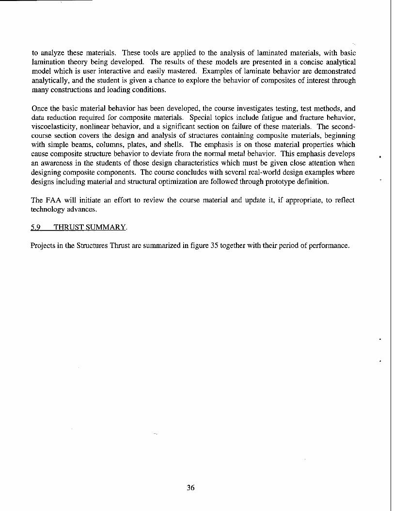
to analyze these materials. These tools are applied to the analysis of laminated materials, with basic lamination theory being developed. The results of these models are presented in a concise analytical model which is user interactive and easily mastered. Examples of laminate behavior are demonstrated analytically, and the student is given a chance to explore the behavior of composites of interest through many constructions and loading conditions.
Once the basic material behavior has been developed, the course investigates testing, test methods, and data reduction required for composite materials. Special topics include fatigue and fracture behavior, viscoelasticity, nonlinear behavior, and a significant section on failure of these materials. The second- course section covers the design and analysis of structures containing composite materials, beginning with simple beams, columns, plates, and shells. The emphasis is on those material properties which cause composite structure behavior to deviate from the normal metal behavior. This emphasis develops an awareness in the students of those design characteristics which must be given close attention when designing composite components. The course concludes with several real-world design examples where designs including material and structural optimization are followed through prototype definition.
The FAA will initiate an effort to review the course material and update it, if appropriate, to reflect technology advances.
5.9 THRUST SUMMARY.
Projects in the Structures Thrust are summarized in figure 35 together with their period of performance.
36
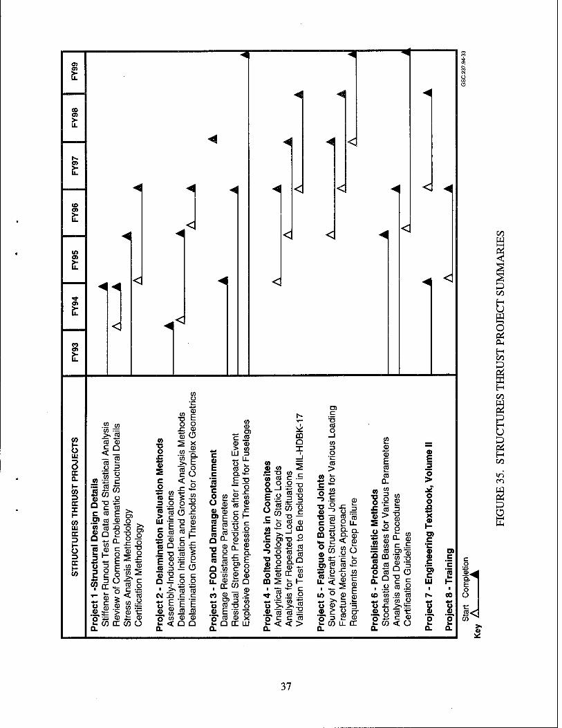
eo OS
o»
(O o>
in
O)
O)
0) H U UJ "9 O DC 0. I- w 3 cc I I- (0 Ul DC 13 H O 3 DC H </>
.<
^^
<|
<
.£2 w
><iS ca a)
<° CO s=
«oil 3W o Q "O '-5 LJ c co c co £
.O) co ^) 'ö> "5 .a
— 0) «B 0 C
= H F
_ o
"*o *~ 0 > Ü c
co T3 O x:
CO ■o o .c Q) S
CO o 'l_
0 E o CD
(5 X a)
■£ a. CO
'co c
>>
CO
o .£ CO 0
_, O
« 3
S § ^ o *= JP. A- w CC
co cu
I5 CO g
< co co£ CO s= CD -C 4= CD CO Ü
- 1
c o V co a c 3 O J5 "co
j! co Q ,E T3 C CD £ ° CO 3
• "2 ■ ><
CM J3 ** F 8 S
.Si. co O co
£<
Ü
2* a ■o c co c •-
11 -EG c c .2 .2 co to c c E E
_co m CD 0 a a
^
CO CD
« CD CD
C CD
E c "5
> UJ
c O co U a3 0 0) °>E n E CO Q
T3 C CO
a o u.
E33
T5 <D CO c
*5 c
CD co
CL £
I 8 559
CO
T3 „ O) Ü « .2.E "QOCUJ
CL
CO 0
<!
<l <J ^
<
<!
m Q x
to ^ 0) CO ^ S"D W r
fSSs .£ t co CD ° o m .5 o»-o 2 o o _0) «j
CD ■D 3
CO
£2 4-< O <D m 2
"cö
D. 0
DC
c o "* ü « .2
»Bffll O c c co
<l
c ID CO O
CO >
*>* o c —
51 ? 2 o B
CO o
CD Zi o) 2 •3 p CO .!= U. <
it 'o 3
0
^^
Q- CD < 0
"is o t: 0 c 5E 0 |
i* 2 0 u. cc
0 0 E 2 co
CL CO
o CO
o
0 >
eo 2 3
0 Ü 2
«8Q. — M
•— co ■= a
J3 CO CO
CO o co v.
CL Q o
CO CO co
U £ 0 o
(1 O ■♦-' k. (/)
CL
CO 0
c £ .2>"CD
82 Qo "g {= co .2
.«G "co co o
c 0 < Ü
0 E 3 O > i£ o o XI
H D) C ~ 0 0 c c E c
UJ
u 0 •■■•« o
CL
CO ft. H
CO
t> 0 "o ft. CL
c o
E o Ü
s< CO ^
><
H U e o CL,
H 00
37
6. MANUFACTURING AND SUPPORTABILITY.
The Manufacturing and Supportability Thrust is concerned with research that will permit safe operations of aircraft from initial flight to retirement by developing inspection methods suitable for detecting defects or anomalies in structures made of advanced materials. For inspection methods to be effective, knowledge of material processing, manufacturing, and assembly methods must be usable by operations personnel.
The FAA is currently stressing the need to consider maintainability as a factor in the aircraft certification process. Information on such issues as accept/reject/repair disposition criteria, repair procedures, and repair validation methods are being requested. One preferred method of substantiation is to include repairs as part of static and repeated-load testing. The multitude of materials being used, the stringent FAA "approved data" requirements, the small amounts of material required for individual repairs, and the shelf life requirements for the current polymer materials, are some of the problems facing aircraft operators in maintaining their aircraft. There is currently an Air Transport Association/ International Air Transport Association/Society of Automotive Engineers (ATA/IATA/SAE) Commercial Aircraft Com- posite Repair Committee (CACRC) tasked with addressing these issues and standardizing aircraft repair materials and procedures.
Government and industry are making progress toward keeping advanced materials cost-competitive. This has been accomplished through innovative manufacturing processes such as vacuum impregnation molding, resin transfer molding, thermoforming, pultrusion, and the incorporation of in-situ control systems into composite fabrication processes. Also, new advanced material forms created by textile processes, such as two-dimensional and three-dimensional weaving, braiding, stitching, and knitting are being developed. These manufacturing processes will produce near net-shaped structural elements with multidirectional fiber architecture. The reduction in part count and fabrication steps will reduce costs while improving the out-of-plane performance.
The FAA will follow these advancements in fabrication processes, tooling, processing science and quality assurance closely, and respond effectively when they appear in commercial certification programs and production commitments. Follow-up efforts also are required in NDE for use when the aircraft are in-service to assure continued airworthiness. Results of research in the Manufacturing and Supportability Thrust will be used by the Aircraft Maintenance and Manufacturing Divisions of the FAA as well as the airlines and repair stations.
The Manufacturing and Supportability Thrust consists of projects concerned with manufacturing quality, continuing airworthiness, and production of handbooks in support of flight standards and inspection functions. NDE of Advanced Materials is a broad project that will provide a database on the capabilities of inspection methods for aircraft structures made with current and future materials. To ensure safe structure during a lifetime of operations, the database developed during the fabrication and certification process must be available for interrogation by maintenance inspectors. NDE for Bonded Joints is a subset of the first project since bonded joints require special emphasis. In supportability, Repair Methodology is a broad project involved in many facets of maintenance including requirements for certifiable repair stations. The Paint Removal project has been singled out for special consideration since this process is quite different for composites than for metals and requires special attention.
38
The relationship of the two handbooks developed in this Thrust to the other handbooks is shown in figure 17. The Safety Inspector Handbook is useful during certification and manufacturing, while the Airworthiness Inspector's Handbook is useful for maintenance situations once the aircraft is in-service.
6.1 NDE OF ADVANCED MATERIALS AND BONDED JOINTS.
The current NDE techniques for composites (e.g., ultrasonics, x-ray, thermography) work in a factory environment. Few have reached a state of development consistent with commercial airline operations e.g., line/ramp and dock/hangar inspections. In-service structures have been exposed, often for many years, to weather and mechanical loading, leaving the surfaces to be inspected roughened by erosion, abrasion, and chipped finishes: this makes inspection difficult. Nondestructive reference standards like drawing information available to the manufacturing inspector, are often not available to the airline inspector. Nondestructive inspection procedures also lack the appropriate resolution to detect fiber waviness and other associated manufacturing and damage encountered in-service. Furthermore, newer processes and structural forms will require development of new inspection methods.
A multipronged effort will be initiated, cognizant of the operating conditions in commercial operations, to develop the NDE capabilities needed to identify detrimental types of manufacturing and in-service defects/damage (e.g., fiber waviness, through-the-thickness definitive impact damage characterization). NDE to verify repair integrity will be identified based on airline depot capability. Heat affected areas of a structural component that have been exposed to fire will be addressed from the NDE aspect.
NDE quality control methods will be established for new fabrication processes being considered for civil aircraft. For example, the following RTM process variables that can affect structural integrity and durability are: degree of consolidation, fiber orientation control and waviness, resin and fiber dis- tribution, fiber location control, fiber damage, final shape tolerances, and void content. NDE techniques and procedures will be established for these variables and for other novel manufacturing methods.
After identifying candidate NDE techniques, the reliability of each method to detect material/structure defects/damage will be determined. However, reliability can be determined only when a large manufacturer and airline database has been accumulated. This information is needed to conduct meaningful damage tolerance repeated-load interval testing and to set inspection intervals.
Small composite airplanes minimize the use of fasteners; essentially they are all-bonded aircraft. For years helicopter rotorblades have employed an all bonded design. Now rotorcraft airframes are being assembled using the same philosophy. Similarly, transport aircraft are adopting an all-bonded approach. Unfortunately, civil and military aircraft certification and in-service experience with secondarily bonded structure has not been totally satisfactory. Manufacturing quality assurance procedures are unable to ensure the structural integrity of bonded joints. There is no repeatable and reliable NDE device currently available that can detect or quantify understrength bonds. The FAA has taken the position that the manufacturer must provide the FAA information stating the extent to which each bonded joint could be defective and the ability of the remaining structure to sustain limit load, i.e., the maximum load that can be experienced in the life of the aircraft. Further, a design device must be provided such that a debond greater than this will not develop in-service. Special conditions specifying this requirement have been applied to many Part 23 aircraft in the past. This amendment became FAR Part 23.573, (August 6, 1993). This design requirement limits the optimization of composite structural designs. If a repeatable
39
and reliable NDE device could be produced that would screen out or quantify understrength bonds, this requirement would be eliminated.
To resolve this problem, the FAA initiated and sponsored two R&D efforts over the past ten years. The first effort, reported in DOT/FAA/CT-84/2, developed a strength screening system based on high power ultrasonics. Because of insufficient analytical base and concerns that the technique may produce undesired effects on long-term durability, the developed method was not pursued further. The second contracted effort has been completed and is reported in DOT/FAA/CT-93/42. The results of this effort have shown that the developed methodology does not give consistent results and therefore, will be difficult to transfer to production use. Results of both projects, however, were useful to build upon as "lessons learned."
Industry state-of-art NDE technologies and those developed by the FAA as part of the Aging Aircraft Program will be reviewed to determine which technologies have the greatest potential for detecting flaws or damage. The Aging Aircraft Program is primarily concerned with detecting cracks in metal structure. However, some attention is placed on bonded joints between metal adherends and metal or composite repair patches. This latter initiative has the most potential of technology transfer to composite bonds NDE. Once a potential method(s) has been identified, research will be conducted to produce a workable prototype model of a device that can be transitioned into industry.
6.2 QUALITY CONTROL OF MANUFACTURING PROCESSES.
The on-going development of new manufacturing processes is quite extensive and significantly different in many ways from present methods. It is important to remain informed about these methods since quality of a product cannot be improved by inspection. Key quality control parameters will be identified so that meaningful quality of product judgments can be made. This will include the pre-processing steps (precure, ply-cut, kitting, out time, automated lay-up) and the processing steps (cure, autoclave controls, tool design), and the post-processing steps (drilling, machining, fastener installation, fit-up).
Once the process is understood, quality control procedures can be established for inspection points and allowable types and sizes of defects as they influence strength and stiffness of the structure. The tests will be conducted on samples representative of the manufacturing process in question.
6.3 REPAIR METHODOLOGY.
Current repair procedures are not standardized, vary considerably, and are costly. An intensive effort is currently underway by national and international air carriers to standardize some areas of the repair procedure through the ATA/IATA/SAE CACRC. Topics now in process of standardization are material selection, preparation for repair (scarfing techniques, etc.), and repair (dimensioning, lay up sequences, bagging, etc.). Types of repairs under consideration are temporary and permanent, and both bonded, (prepreg lay-up, wet lay-up), and bolted.
The FAA will initiate a research program to assist CACRC in standardizing repair procedures. A project is being funded to develop human factors capability in repair by developing training materials. Another area of interest is the use of generic materials for both repair patches and adhesives to allow use of common repair materials irrespective of which original manufacturer fabricated the part. Test data will be generated to assure aircraft manufacturers of the equivalency of the generic material or process, to
40
that called out in given Structures Repair Manuals. Data generated on patch and adhesive materials will be useful for repair of composite and metallic structures, e.g., aging aircraft application. The informa- tion developed by this research effort should be incorporated into the composite material section of FAA AC 43.13-1A and the Aviation Safety Inspector—Maintenance Handbook to permit more flexibility in repair approvals.
Another planned task is to simplify repair apparatus by investigating resins that do not require elevated temperature curing while retaining acceptable mechanical properties. Using ultrasonic curing to shorten repair time will also be investigated.
As the HSCT enter service, long range activities involve the repair of aircraft structure made of MMC and CMC composites. Since very little research has been conducted in this area, the first activity will be identification of the effects of different types of defects/damage in MMCs and CMCs. Repair inspection procedures, repair techniques for individual damage types, and composite repair databases will then be developed for all classes composites, i.e., PMCs, MMCs, and CMCs.
6.4 PAINT REMOVAL.
Paint removal methods include mechanical abrasion, chemical dissolution, chemical decomposition, coating embrittlement, or reversal of adhesion. Unlike metals, the effect of repetitive paint removals on composite material surfaces has not been studied extensively. It is generally known that both chemical and mechanical techniques may degrade composite material properties. Because most solvents and chemical paint strippers are not considered acceptable for use with composites, the aviation industry and DoD are focusing considerable attention on plastic media blasting (PMB). Various types of grit, lasers, and water jets are now being evaluated for paint stripping to determine the advantages and disadvantages of each method and its effect on composite structure.
A project has been initiated to evaluate advances made in these paint stripping methods. The purpose of this is to ensure that the effects of repeated paint removals will not affect significantly the near- and long-term durability of composite structures. This research will include the development of paint removal criteria/guidelines for use by industry.
6.5 SAFETY INSPECTOR HANDBOOK.
For a number of years, composite materials have been selected as the material of choice in civil aircraft structural applications. Recognizing that the FAA Aircraft Manufacturing Division's safety inspectors would be required to monitor the manufacture of such airframes at OEM facilities, the FAA supported an effort to develop an aviation (manufacturing) safety inspectors composite material handbook. The product provided the information necessary for the inspector to perform his mission. The handbook, An Engineering Compendium on the Manufacture and Repair of Fiber-Reinforced Composites, report number DOT/FAA/CT-87/9, was issued in 1987.
Since this is an evolving technology, advances are continually made across all classes of composites, e.g., PMC, MMC, CMC, and C/C. This is especially true in the manufacturing area. A mandate has been issued by NASA and the USAF that their near-term research will be focused on reducing the weight and cost of PMC by 50 percent. To achieve this goal, significant advances are needed in manufacturing.
41
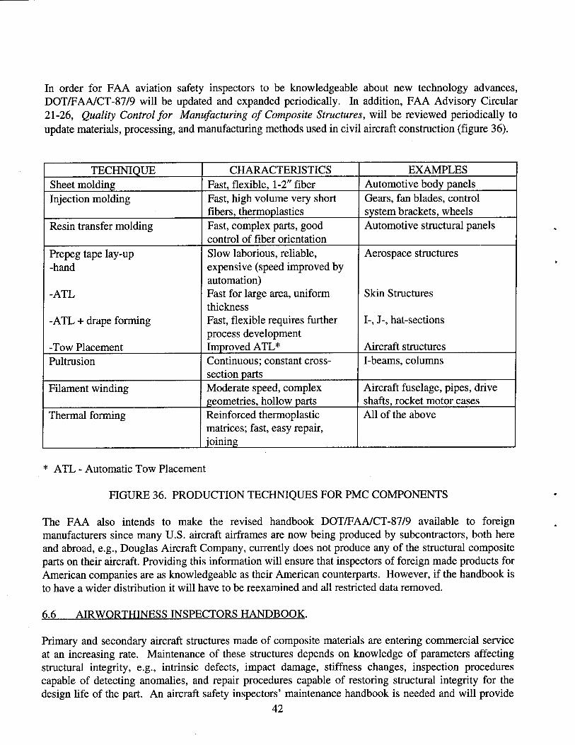
In order for FAA aviation safety inspectors to be knowledgeable about new technology advances, DOT/FAA/CT-87/9 will be updated and expanded periodically. In addition, FAA Advisory Circular 21-26, Quality Control for Manufacturing of Composite Structures, will be reviewed periodically to update materials, processing, and manufacturing methods used in civil aircraft construction (figure 36).
TECHNIQUE CHARACTERISTICS EXAMPLES Sheet molding Fast, flexible, 1-2" fiber Automotive body panels Injection molding Fast, high volume very short
fibers, thermoplastics Gears, fan blades, control system brackets, wheels
Resin transfer molding Fast, complex parts, good control of fiber orientation
Automotive structural panels
Prepeg tape lay-up -hand
-ATL
-ATL + drape forming
-Tow Placement
Slow laborious, reliable, expensive (speed improved by automation) Fast for large area, uniform thickness Fast, flexible requires further process development Improved ATL*
Aerospace structures
Skin Structures
I-, J-, hat-sections
Aircraft structures Pultrusion Continuous; constant cross-
section parts I-beams, columns
Filament winding Moderate speed, complex geometries, hollow parts
Aircraft fuselage, pipes, drive shafts, rocket motor cases
Thermal forming Reinforced thermoplastic matrices; fast, easy repair, joining
All of the above
* ATL - Automatic Tow Placement
FIGURE 36. PRODUCTION TECHNIQUES FOR PMC COMPONENTS
The FAA also intends to make the revised handbook DOT/FAA/CT-87/9 available to foreign manufacturers since many U.S. aircraft airframes are now being produced by subcontractors, both here and abroad, e.g., Douglas Aircraft Company, currently does not produce any of the structural composite parts on their aircraft. Providing this information will ensure that inspectors of foreign made products for American companies are as knowledgeable as their American counterparts. However, if the handbook is to have a wider distribution it will have to be reexamined and all restricted data removed.
6.6 AIRWORTHINESS INSPECTORS HANDBOOK.
Primary and secondary aircraft structures made of composite materials are entering commercial service at an increasing rate. Maintenance of these structures depends on knowledge of parameters affecting structural integrity, e.g., intrinsic defects, impact damage, stiffness changes, inspection procedures capable of detecting anomalies, and repair procedures capable of restoring structural integrity for the design life of the part. An aircraft safety inspectors' maintenance handbook is needed and will provide
42
the information necessary for FAA inspectors to ensure that the composite structure on a commercial aircraft is being maintained in an airworthy condition. The handbook will include considerations being addressed by the CACRC.
AC 43.13-1 A, Acceptable Methods, Techniques, and Practices—Aircraft Inspection and Repair provides acceptable inspection and repair methods, techniques, and practices when there are no manufacturer repair or maintenance instructions available. The information is intended for use when inspecting minor repairs and as a basis for FAA data approval for major repairs. However, little information is provided on the repair of composite structure. Information developed for this handbook will be used to develop, support, and provide the background for a composite materials section in FAA AC 43.13-1A and both will be evaluated and updated periodically to accommodate the evolution of materials, processes, inspection techniques, new design concepts, and repair concepts.
6.7 THRUST SUMMARY.
Projects in the Manufacturing and Supportability Thrust are summarized in figure 37 together with their period of performance.
43
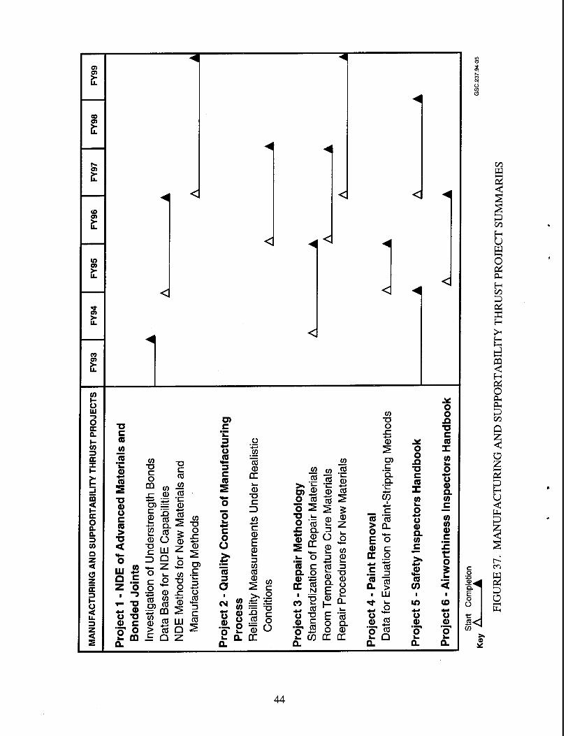
CO
(O
m OS
o>
o>
CO I- U UJ
o DC 0. I- tn 3 DC X
03 < I- DC o o. 0. 3 CO Q z <
u <
< s
<
<
C (0
w JO a> *-> (6
■o a) o c (0 >
■D <
CO ■o c o
CO
c CO
CO ■§
Ö) = c 0
0 .55 0
"co CO Q.
_ CO CD O .W
uj £. 9 -E z o
i -3 T- -O +* <J) U 7 a> c
C Z)
5 o
O) c
u n
<♦- 3 C (0
o o I-
c o Ü
Z. Z ^ g> = co .£
•2 CD
CO 0 > c
CO -I—»
CO Q
■a -i o •4-» r Ü
■•—» CO CD 2 3
C III CO a i>
(0 3 a « 8 o g Ä o
o w
"cö CD
GC k.
■a c ID CO c CD E S> 13 CO CO Is >..2
CO o ^ Ü
<
<
_co CO
&& O CO
o 2 O 'cö £ a. <D
_co jo .£! co a) CD co
"CO ^
a,®
5o »- o « c a o 0 v=
fc, CO "5 "a O *-
=3 0 CO 3
!*
E -S O Q. O 0
<1
co T3 O
0
C "o. Q.
■*^
(f)
o o Si "O c (0 X (A
o as CO Ü > Q_ 0 o ■+. a F O W 0 c
o c >.
c CO 3 0
as CO (0 a. > (0
i UJ 1
<* 1_
o in 4-* ** u o 0 CO 0 o CO o k. Q i_ a. Q.
o o
T3 C (Q X (A
U 0 a co c CO tn 0 c
o
co *-> u 0
Q. E o O
S« CO ^
00 W 2 <
C/3
H U a <—> o cm H 1/5
ei X H
O OH PL,
CO
Q
Ü Z 2 H U <
p
en
Ü
44
7. PRODUCTS.
Organic matrix composites have been and are currently in use in aircraft airframes. However, some certification issues for composite structures for commercial aircraft have not been adequately resolved. This has resulted in a final product that may not be optimum. This plan addresses these issues, as well as those that have been identified by FAA airworthiness and certification offices as being in need of consensus between government and industry. These include certification for:
a. Foreign object impact damage, b. Damage incurred during manufacturing, c. Explosive decompression of composite fuselage components, d. Damage initiated at design details such as stiffener terminations, e. Repeated loading effects, f. Static and dynamic behavior of adhesive and mechanically fastened joints, and g. Adhesive bonds.
Technical information will be developed to provide a basis for certification and airworthiness strategies for the above topics.
Other items addressed by the plan will result in data that will be needed in the out-years as emerging technologies mature. These will include technical information on new materials and material forms, e.g., thermoplastic matrices, toughened epoxy matrices, and reinforcement forms such as braiding and stitching. This plan is structured in a way that the information will be available quickly.
The use of probabilistic structural analysis and design criteria for composite structures has already been applied, in a limited extent, to commercial aircraft. This methodology promises to be more widely influential in the future. An information base on this approach is critical if the FAA is to make knowledgeable judgments in its application.
Issues related to repair of composite structures have become more pressing as more service usage accumulates on composite components. Now a database is needed of standard repair materials that can be used on all aircraft types and that provides flexibility in storage and inventory at airline repair depots.
This plan will continue to provide relevant training material by publishing for engineers, inspectors, and repair technicians. The activity in support of the Failure Analysis Handbook will continue to provide information to accident investigation authorities.
In summary, the database of information and handbooks generated by this program plan will furnish a vehicle for technology transfer from researchers to the customer base (FAA, industry) in technologies that have been identified by the customer as necessary for the health of U.S. aircraft industry.
45
8. REFERENCES.
1. Whitehead, R.E., NASA Aeronautics and Subsonic Transportation Strategy, Fourth NASA/DoD Advanced Computer Technology Conference.Utah: Salt Lake City, June 1993.
2. National Advanced Composites Strategic Plan, published by National Center for Advanced Technologies (NCAT), September 1991.
3. Whitehead, R.S., Kan, H.P., Cordero, R., and Saether, E.S., Certification Testing Methodology for Composite Structure, DOT/FAA/CT-86/39, October 1986.
4. McCarty, J., Advanced Materials & Structures Study, January 1990.
5. Air Force Guide Specification, Aircraft Structures, General Specification for, June 1990 USAF AFGS-87221A.
6. Rouchon, J., Certification of Large Airplane Composite Structures, Recent Progress and New Trends in Compliance Philosophy, 17th ICAS Congress, Sweden: Stockholm, 1990.
«U.S. GOVERNMENT PRINTING OFFICE: 1995-60ll-08l-00227
46