ASME Y14.5 presentation by Alex Krulikowski May 2005 ASME Y14.5 Proposal on Feature of Size.
PROGRAM
• Welcoming remarks – 8:30 A.M. o Archie R. Anderson, Seminar Leader
Immediate Past Chair, Y14/SC 5 Owner, Dimensional Dynamics, LLC
o Frank Bakos, Chairman, Y14 Committee Consultant
• Introduction to Y14 Standardization – Archie R. Anderson o Companion Standards Y14.5.1 and Y14.5.2 o Associated Standards Y14.43 and Y14.41
• Development process and overview of the changes to Y14.5 Presenter: Archie R. Anderson
• Changes to Section 1 [Scope, Definitions, and General Dimensioning]
Presenter: Martin P. Wright, Design Engineer Senior Staff, Lockheed Martin Aeronautics Company o Q & A
• Changes to Section 2 [General Tolerancing and Related Principles] Presenter: Norman W. Cutler, President, Dimensional Management Inc.
o Q & A
• Section 4 [Datum Reference Frames] Presenters: Alvin G. Neumann, President/Director, Tech Consultants Inc. Donald E. Day, President, Tec-Ease, Inc.
o Q & A
• Section 5 [Tolerances of Form] Presenter: Don W. Shepherd, PhD, Owner, Shepherd Industries
o Q & A
• Section 6 [Tolerances of Orientation] Presenter: Don W. Shepherd, PhD
o Q & A
• Section 7 [Tolerances of Location] Presenter: Bruce A. Wilson, Technical Fellow, The Boeing Company
o Q & A
• Section 8 [Tolerances of Profile] Presenter: Archie R. Anderson
o Q & A
• Section 9 [Tolerances of Runout] Presenter: Don W. Shepherd, PhD
o Q & A
• Questions and Answers Moderator: Archie R. Anderson
• Closing Remarks – Archie R. Anderson
Expected Closing Time: 5 P.M.

Development Process and Overview of Y14.5-2009 Changes
Archie R. Anderson Chairman Y14.5 - 2009

Development Process
• ASME Y14.5 Dimensioning and Tolerancing is a subcommittee of Y14 Engineering Drawing Practices under the auspices of the American Society of Mechanical Engineers (ASME).

Development Process
• Y14 has 25 active subcommittees covering all aspects of Engineering Drawing Practices i.e. Drawing Sheet Size and Format, Pictorial Drawings, Dimensioning and Tolerancing, Certification, Digital Product Definition Data Practices, and many more.

Development Process
• All standardization is voluntary and the subcommittee consists of individuals from industry, academia, National Laboratories, self-employed individuals and the Department of Defense.

Development Process
• Industries represented– Aerospace– Automotive (active and retired)– Earth Moving Machinery
Manufactures– Office Furniture (retired)– Photographer / Office Reproduction
(retired)– Dimensional Analysis Software
Development

Development Process
• National Laboratories– Los Alamos National Laboratory
• Universities– Ohio University, Athens, Ohio– Purdue University

Development Process
• Development of Y14.5-2009 started in January 1995 in Sarasota, Florida.
• The Y14.5 subcommittee meets in May and October each year at different cities around the country.

Development Process
• The process of the revising Y14.5 began with resolving deferred comments from the 1994 Public Review and proposals from the membership of Y14.5.
• The subcommittee was organized in Working Groups with a leader appointed for each WG.

Development Process
• Working Group Leaders– Section 1 Marty Wright – Lockheed
Martin Aeronautics Co.– Section 2 Norm Cutler –
Dimensional Management, Inc. (Retired Poloraid)
– Section 3 Archie Anderson –Dimensional Control Systems, Inc. / Dimensional Dynamics, LLC (Retired GM)

Development Process
• Working Group Leaders (Cont.)– Section 4 Al Neumann – Technical
Consultants, Inc.– Section 4 – Assisted by Don Day-
Tec-Ease, Inc (Formerly Monroe Community College)
– Sections 5,6,9 Dr. Don Shepherd –Shepherd Industries (Formerly Northern Illinois University)

Development Process
• Working Group Leaders (Cont.)– Section 7 Bruce Wilson – The
Boeing Company– Section 8 Dennis Karl – Karl
Engineering (Retired Ford)

Development Process
• Working Group Leaders (Cont.)– Appendix A, C, D Archie Anderson– Appendix B Paul Drake Jr. –
MechSigma Consulting, Inc. (Formerly Texas Instrument)
– Appendix E Frank Bakos – Frank Bakos Associates (Formerly Kodak)

Overview of Revisions
• One of the major revisions is the reformatting of the Standard, the order of the sections and material within the sections without reversing any of the 1994 principles.- Section 1 Scope, Definitions, and
General Dimensioning- Section 2 General Tolerancing and
Related Principles- Section 3 Symbology- Section 4 Datum Reference Frames

Overview of Revisions
- Section 5 Tolerances of Form- Section 6 Tolerances of Orientation
- Section 7 Tolerances of Location- Section 8 – Tolerances of Profile- Section 9 – Tolerances of Runout

Overview of Revisions
- Appendix A – Principle Changes and Improvements- Appendix B – Formula for Positional
Tolerancing- Appendix C – Form, Proportion, and
Comparison of Symbols- Appendix D – Former Practices- Appendix E – Decision Diagram for
Geometric Controls
Overview of Revisions
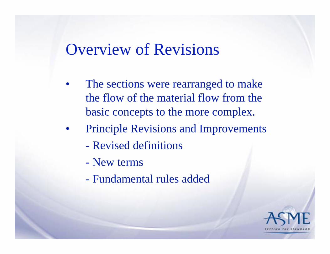
• The sections were rearranged to make the flow of the material flow from the basic concepts to the more complex.
• Principle Revisions and Improvements- Revised definitions- New terms- Fundamental rules added
Overview of Revisions
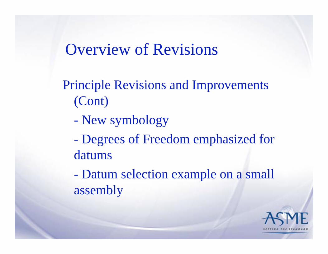
Principle Revisions and Improvements (Cont)- New symbology- Degrees of Freedom emphasized for datums- Datum selection example on a small assembly
Overview of Revisions
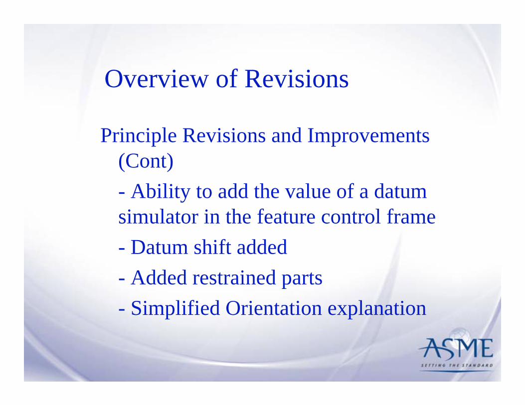
Principle Revisions and Improvements (Cont)- Ability to add the value of a datum simulator in the feature control frame- Datum shift added- Added restrained parts- Simplified Orientation explanation

Overview of Revisions
Principle Revisions and Improvements (Cont)- Major reformatting of section on location tolerances- Expanded coverage of composite positional tolerancing- Expanded coverage of profile tolerancing
Overview of Revisions
• There will be an opportunity for questions following each presentation. The answers and comments are the opinion of the presenters and do not constitute an official ASME interpretation of the standard.

Section 1Scope, Definitions and General Dimensioning
Martin P. Wright
Section 1 Work Group Leader

Definition ConsolidationThe following are terms that have been traditionally defined
within the body of the standard, but now appear in paragraph 1.3 with a cross-reference to the paragraph where the definition is found.
• True Profile• Free-State Variation
• Runout• Cylindricity
• Simultaneous Requirement• Datum Reference Frame
• Straightness• Diameter, Average
• Statistical Tolerancing• Feature Control Frame
• Symmetry• Feature-Relating Tolerance Zone Framework (FRTZF)
• Flatness
• Profile• Coplanarity
• Position• Concentricity
• Perpendicularity• Coaxiality
• Pattern-Locating Tolerance Zone Framework (PLTZF)
• Circularity (Roundness)
• Parallelism• Angularity
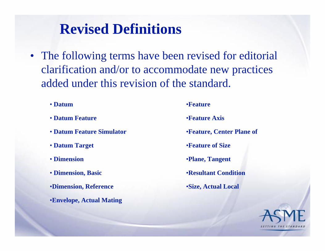
Revised Definitions
• The following terms have been revised for editorial clarification and/or to accommodate new practices added under this revision of the standard.
•Size, Actual Local•Dimension, Reference
•Envelope, Actual Mating
•Feature, Center Plane of• Datum Feature Simulator
•Resultant Condition• Dimension, Basic
•Plane, Tangent• Dimension
•Feature of Size• Datum Target
•Feature Axis• Datum Feature
•Feature• Datum

Newly Added Definitions• The following new terms have been added to
support new practices added under this revision of the standard.
• Free State
• Uniform Tolerance Zone• Envelope, Actual Minimum Material
• Regardless of Material Boundary (RMB)• Complex Feature
• Pattern• Boundary, Maximum Material (MMB)
• Non-Uniform Tolerance Zone• Boundary, Least Material (LMB)
• New and revised terms will be illustrated under the sections where the terms are applied.
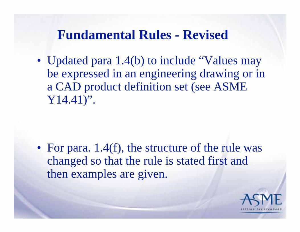
Fundamental Rules - Revised
• Updated para 1.4(b) to include “Values may be expressed in an engineering drawing or in a CAD product definition set (see ASME Y14.41)”.
• For para. 1.4(f), the structure of the rule was changed so that the rule is stated first and then examples are given.

Fundamental Rules - New• Added para 1.4(k) “A zero basic dimension
applies where axes, centerplanes or surfaces that are shown congruent on a drawing and geometric controls establish the relationship between the features.”
• Added para 1.4(p) “Where a coordinate system is shown on the drawing, it shall be right-handed unless otherwise specified. Each axis shall be labeled and the positive direction shown.”
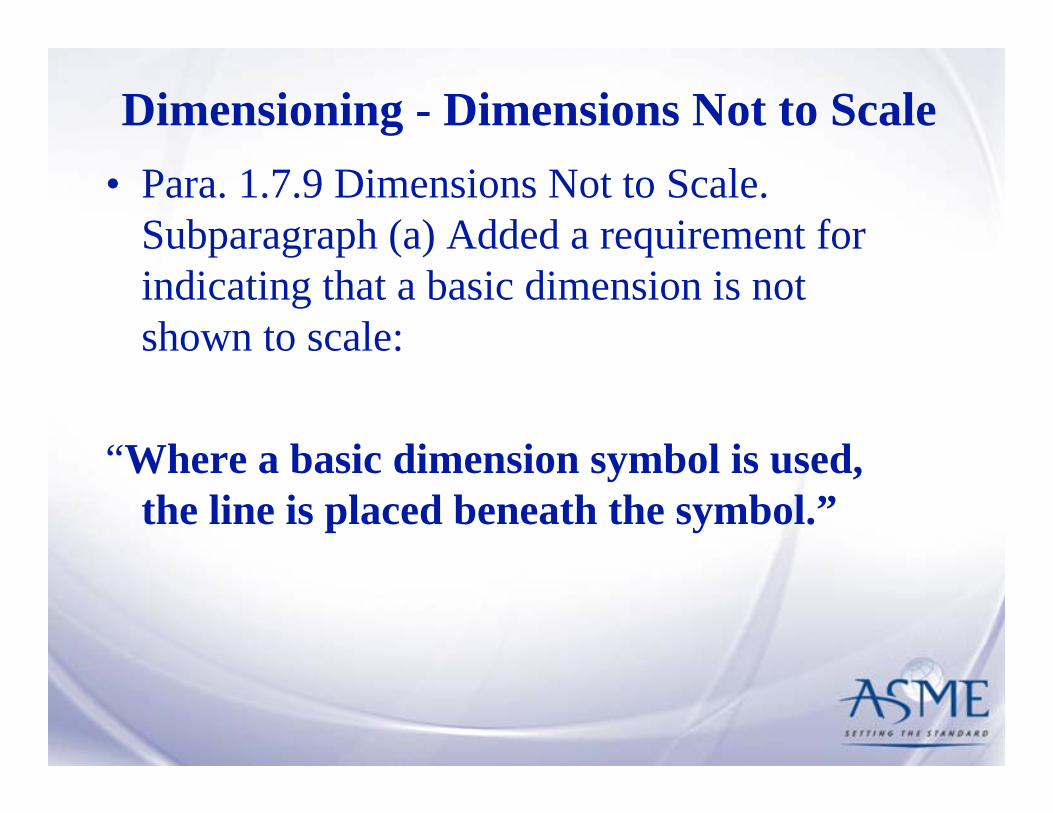
Dimensioning - Dimensions Not to Scale• Para. 1.7.9 Dimensions Not to Scale.
Subparagraph (a) Added a requirement for indicating that a basic dimension is not shown to scale:
“Where a basic dimension symbol is used, the line is placed beneath the symbol.”

Dimensioning - Rounded Ends and Slotted Holes
• Methods for dimensioning Rounded Ends and Slotted Holes have been consolidated under paragraph 1.8.4 and Figures 1-29 & 1-30.

Dimensioning - Round Holes• Para 1.8.10 Round Holes. Added a statement that
additional clarification may be required when indicating THRU holes for multiple features.
“Where it is not clear that a hole goes through, the notation THRU follows a dimension. Where multiple features are involved, additional clarification may be required.”

Dimensioning - Spotfaces• Para 1.8.14 Spotfaces was updated to add the following:
– Where applicable, a fillet radius may be indicated for the spotface.
– In some cases, such as with a through hole, a notation may be necessary to indicate the surface to be spotfaced.
• Figure 1-41 has been updatedto illustrate the new symbol for indicating a spotface.
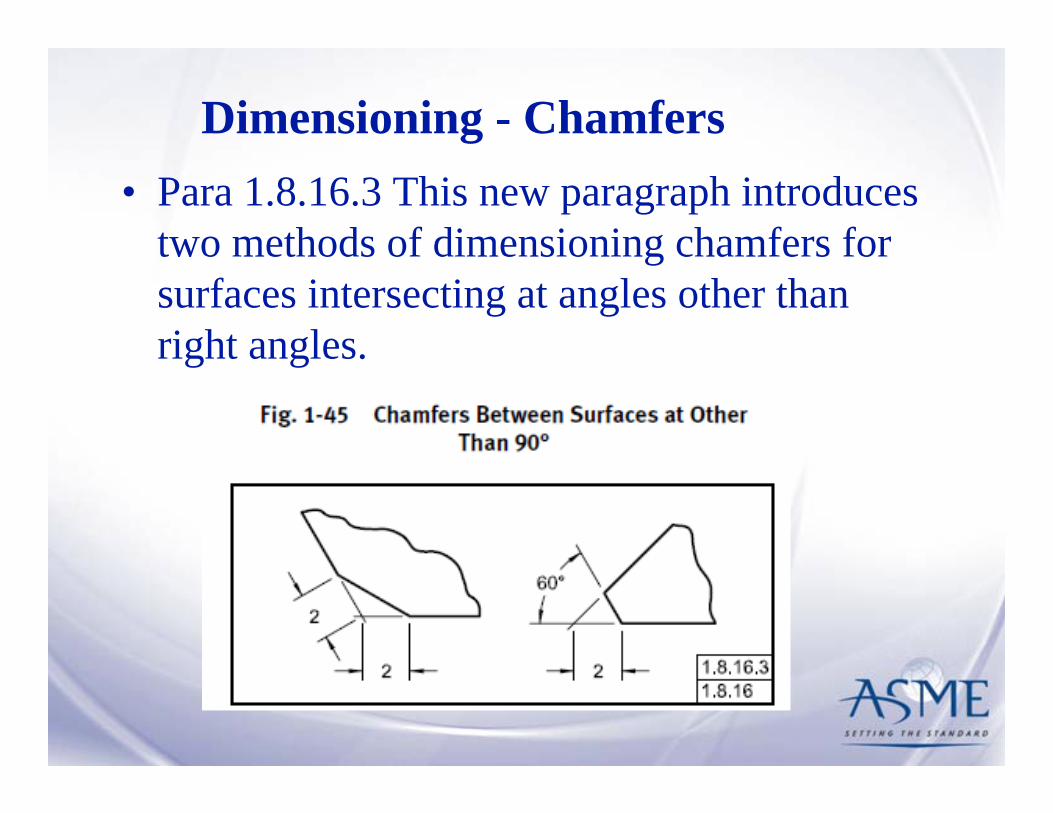
Dimensioning - Chamfers• Para 1.8.16.3 This new paragraph introduces
two methods of dimensioning chamfers for surfaces intersecting at angles other than right angles.

Questions??
1
Section 2General Tolerancing and
Related Principles
Norman W. CutlerPresident
Dimensional Management Inc.
10/2009

Paragraph 2.1.1 has been revised to emphasize /encourage the use of basic dimensions and geo- metric tolerancing as the preferred method of controlling the form, orientation, and location of features.The use of direct tolerancing methods, limit dimensioning and plus minus tolerancing should be used to control the size of features only.
2

2.1.1 ApplicationTolerances may be expressed as follows:(a) as direct limits or as tolerance values applied directly to a dimension. See para. 2.2 (b) as a geometric tolerance as described in Sections 5 through 9.(c) in a note or table referring to specific dimensions.(d) as specified in other documents referenced on the drawing for specific features or processes.(e) in a general tolerance block referring to all dimensions on a drawing for which tolerances are not otherwise specified.
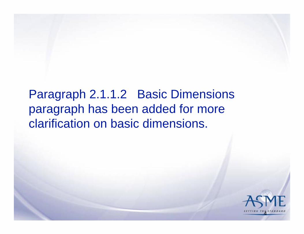
Paragraph 2.1.1.2 Basic Dimensions paragraph has been added for more clarification on basic dimensions.
4

2. 1.1.1 Basic dimensions, Basic dimensions may be indicated on the drawing in the following ways:(a) applying the basic dimensions symbol to each of the basic dimensions . See fig. 7-1, illustrations (a) and (b). (b) specifying on the drawing (or in a document reference on the drawing) a general note such as: untoleranced dimension are basic. See fig. 7 illustration (c)Note: Where using this method a plus/ minus general tolerance is not allowed.(c) For specifying and querying basic dimensions on models or digital drawings with models, see ASME Y. 14.41

Paragraph 2.1.1.4 on implied 90 degree angles has been expanded to include basically dimensioned angles controlled by geometric tolerancing
6

2.1.1.4 Implied 90° or 0° Basic Angle. Where center lines and surfaces are depicted on 2-D orthographic engineering drawings intersecting at right angles or parallel to each other and basic dimensions or geometric tolerances have been specified, implied 90° or 0° basic angles are understood to apply. The tolerance on the feature associated with these implied 90° or 0°basic angles is provided by feature control frames that govern the location, orientation, profile, or runout of features. See para. 1.4(J) and( K).
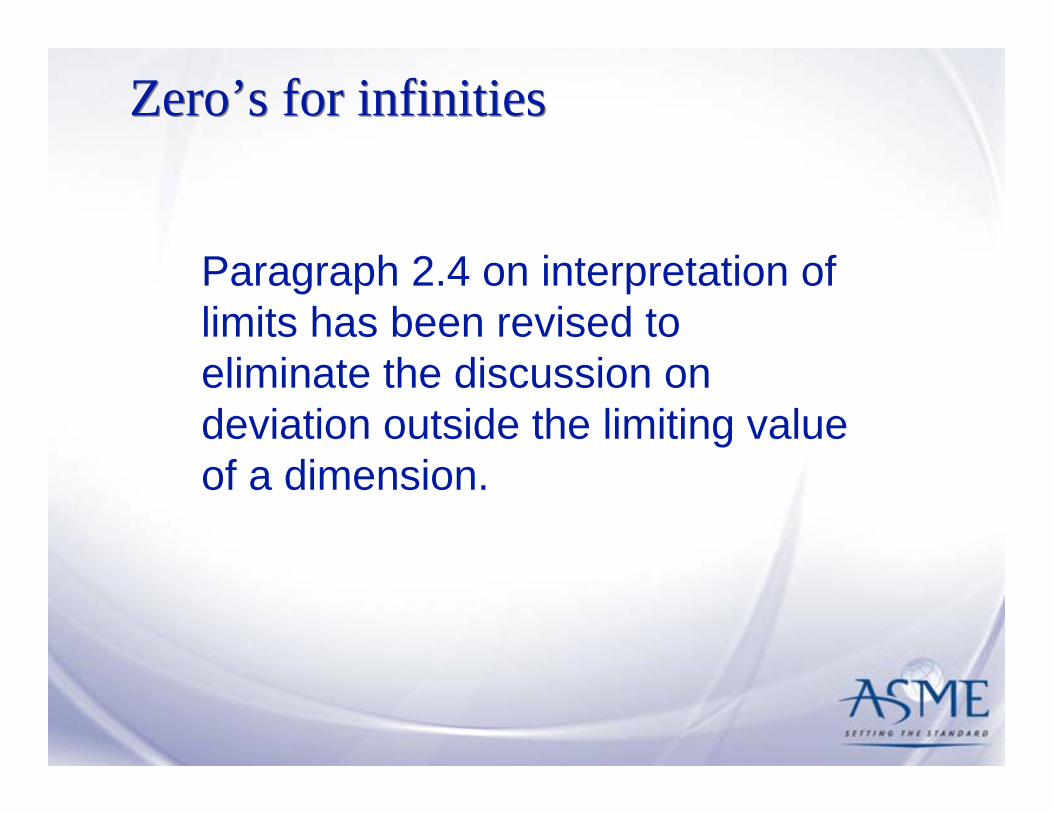
Zero’s for infinitiesZero’s for infinities
Paragraph 2.4 on interpretation of limits has been revised to eliminate the discussion on deviation outside the limiting value of a dimension.
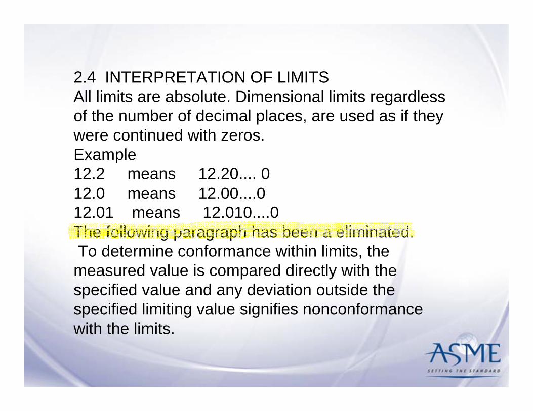
2.4 INTERPRETATION OF LIMITSAll limits are absolute. Dimensional limits regardless of the number of decimal places, are used as if they were continued with zeros. Example 12.2 means 12.20.... 012.0 means 12.00....012.01 means 12.010....0The following paragraph has been a eliminated.To determine conformance within limits, the measured value is compared directly with the specified value and any deviation outside the specified limiting value signifies nonconformance with the limits.

Zero tolerance accumulation with basic dim.Zero tolerance accumulation with basic dim.
In para.2.6, a note has been added on the effect of tolerance accumulation when using basic dimensioning.
10

NOTE: When basic dimensions are used. There is no accumulation of tolerances. A geometric tolerance is required to create the tolerance zone. In this case, the style of dimensioning ( chain, baseline, direct) is up to the discretion of the user. Locating features using directly tolerance dimensions is not recommended.

In Para. 2.7.1, Rule#1 has been expanded for clarification.
12
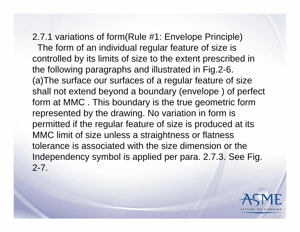
2.7.1 variations of form(Rule #1: Envelope Principle)The form of an individual regular feature of size is
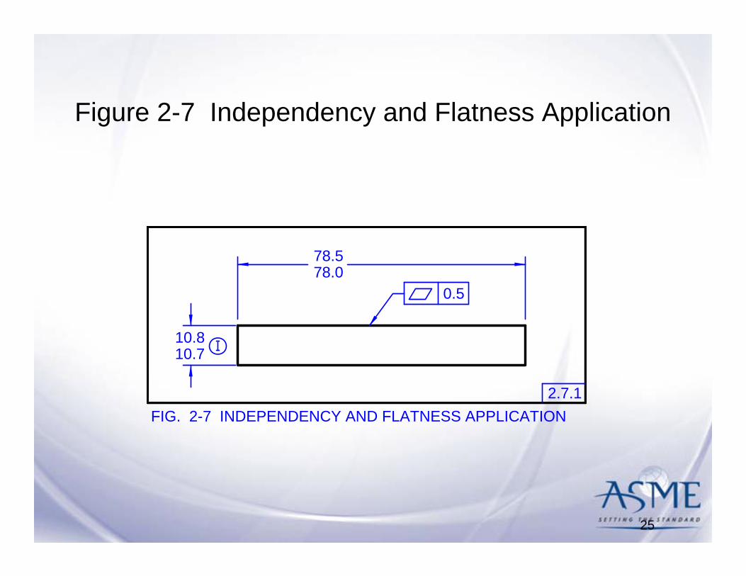
controlled by its limits of size to the extent prescribed in the following paragraphs and illustrated in Fig.2-6.(a)The surface our surfaces of a regular feature of size shall not extend beyond a boundary (envelope ) of perfect form at MMC . This boundary is the true geometric form represented by the drawing. No variation in form is permitted if the regular feature of size is produced at its MMC limit of size unless a straightness or flatness tolerance is associated with the size dimension or the Independency symbol is applied per para. 2.7.3. See Fig. 2-7.

(b) Where the actual local size of a regular feature of size as the product from MMC towards LMC, a local variation in form is allowed equal to the amount of such departure. (c) There is no default requirements for a boundary of perfect form at LMC. Thus a regular feature of size produced at its LMC limit on size is permitted to very from true form to the maximum variation allowed by the boundary of perfect form at MMC.(d) In cases where a geometric tolerances specified to apply at LMC, perfect form at LMC is required. See Para. 7.3.5

In Para. 2.8.4, Perfect form at LMC when a tolerance applies at LMC is clarified.
15

2.8.4 Effect of LMCWhere a geometric tolerance is applied on an LMC basis, perfect form at LMC is required. Perfect form at MMC is not required. This is the reciprocal of the MMC concept. See figure 2 - 11. Where a geometric tolerance is applied on LMC basis, the allowed tolerance is dependant on the unrelated actual minimum material envelope on the considered feature. The tolerance is limited to the specified value if the feature is produced at its LMC limit the size. Where the unrelated actual minimum material envelope of the future has departed from LMC, an increase in the tolerance equal to the amount of such departure is allowed. The total permissible variation in position is maximum when the feature is at MMC unless a maximum is specified. See Figs. 7-14 and 7-15.
A new definition addedA new definition added
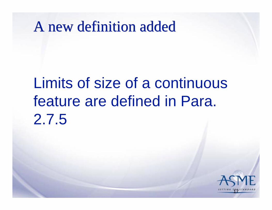
Limits of size of a continuous feature are defined in Para. 2.7.5
17

2 .7 .5 Limits of Size and Continuous Features of SizeThe note “CONTINUOUS FEATURE” or continuous future symbol is used to identify a group of two or more features of size where there is a requirement that they be treated geometrically as a single feature of size. When using the continuous feature symbol, extension lines between the features may be shown or omitted; however, extension lines by themselves do not indicate a continuous future. See Figs. 2 -8 through 2-10.

New definition added
The placement of the tangent plane symbol within the feature control frame is specified in Para. 2.16
19
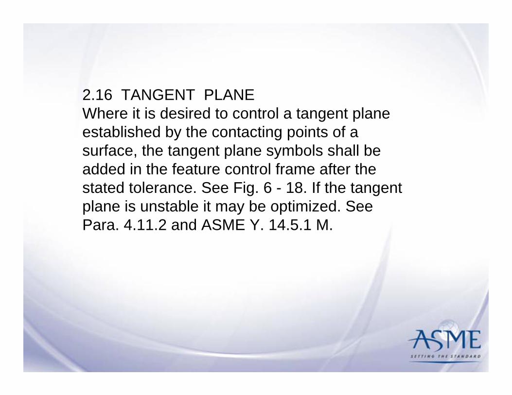
2.16 TANGENT PLANEWhere it is desired to control a tangent plane established by the contacting points of a surface, the tangent plane symbols shall be added in the feature control frame after the stated tolerance. See Fig. 6 - 18. If the tangent plane is unstable it may be optimized. See Para. 4.11.2 and ASME Y. 14.5.1 M.

Removed Para. 2.11.1
Paragraph 2.11.1 in ASME Y14.5M- 1994 (Virtual Condition) has been removed.This concept is covered in Para. 2.11, Boundary Conditions
21

Removed Para. 2.11.2
Paragraph 2.11.2 in ASME Y14.5M-1994 (Resultant Condition) has been removed. This concept is covered in Para. 2.11, Boundary Conditions
22

Removed Par. 2.11.3
Paragraph 2.11.3 in ASME Y14.5M-1994 (Datum Features at Virtual Condition) has been removed. This Concept is covered in Para. 4.11.9 (Datum Feature Shift / Displacement) and Para. 7.3.6 (Datum Feature Modifiers In Positional Tolerancing).
23

New Figures
24
25
10.810.7
78.578.0
I
0.5
2.7.1FIG. 2-7 INDEPENDENCY AND FLATNESS APPLICATION
Figure 2-7 Independency and Flatness Application

26
2.7.5FIG. 2-8 CONTINUOUS FEATURE, EXTERNAL CYLINDRICAL
Envelope of perfect form at MMC.No portion of the continuous featureshall extend outside this envelope.
22.1 22.1
Each cross section shall bewithin the limits of size.
CF
3.3.23
This on the drawing Means this
22.222.1
22.2
Figure 2-8 Continuous Feature, External Cylindrical

27
Envelope of perfect form at MMC.No portion of the continuous featureshall extend inside this envelope.
Extension linesmay be shown oromitted.
Extension linesmay be shown oromitted.
(a)
(b)
22.1
22.2
22.2
- or -
22.1 - 22.2
CF
CF
Each cross section shall bewithin the limits of size
3.3.232.7.5
FIG. 2-9 CONTINUOUS FEATURE, INTERNAL CYLINDRICAL
This on the drawing Means this
22.222.1
Figure 2-9 Continuous Feature, Internal Cylindrical

28
2.7.5FIG 2-10 CONTINUOUS FEATURE, EXTERNAL WIDTH
This on the drawing Means this
Envelope of perfect form at MMC.No portion of the continuous featureshall extend outside this envelope.
28.63 28.52 28.52 28.52CF
Each cross section shall bewithin the limits of size.
28.5228.63
3.3.23
Figure 2-10 Continuous Feature, External Width

29
20.1 (MMC)
20 (LMC)
20.1 (MMC)
20.2 (LMC)
20.1 (MMC)
20 (LMC)
20.1 (MMC)
LMC Perfectform boundary
LMC Perfectform boundary
20.2 (LMC)
0 L
0 L AA
2.8.4FIG. 2-11 EXTREME VARIATIONS OF FORM ALLOWED BY A GEOMETRIC TOLERANCE - PERFECT FORM AT LMC
THIS ON THE DRAWING ALLOWS THIS
20.220.1
20.020.1
Figure 2-11 Extreme variation of Form Allowed by
a geometric tolerance – Perfect Form at LMC

Consolidated Figures
Consolidated Old Figures 2.7 ,2.8, 2.9, 2.10, 2.11, 2.12
into
New figures 2.12, 2.13, 2.14, 2.15, 2.16, 2.16, 2.17
30

31
FIG. 2-12 VIRTUAL AND RESULTANT CONDITION BOUNDARIES USING MMC CONCEPT-INTERNAL FEATURE
1.3.21.3.5
C
B
A
30.530.1
30.10.1
30
MMC of featurePositional zone at MMCVirtual condition (Inner boundary)
geometric tolerance.material condition PLUS its applicablefeature is a single value equal to its leastThe resultant condition (RC) of the internal
applicable geometric tolerance.maximum material condition MINUS itsfeature is a constant value equal to itsThe virtual condition (VC) of the internal
30.130.230.330.430.5HOLE
MMC
LMCVCTOL
0.20.1
0.40.3
0.5
30
RC31
RESULTANT CONDITION BOUNDARY
VIRTUAL CONDITION BOUNDARY
0.5 Positionalzone at LMC
LMC of featurePositional zone at LMCResultant condition (Outer boundary)
0.1 Positionalzone at MMC
possible locationsat 4 extreme
30.1 Hole shown
30.50.5
31
–
+
at 4 extremepossible locations
30.5 Hole shown
0.1 M A B C1.3.51
This on the drawing Means this
1.3.672.11

32
B
A
30.530.1
30.10.5
29.6
30.50.1
30.6
applicable geometric tolerance.maximum material condition MINUS itsfeature is a single value equal to itsThe resultant condition (RC) of the internal
geometric tolerance.least material condition PLUS its applicablefeature is a constant value equal to itsThe virtual condition (VC) of the internal
30.130.230.330.430.5HOLE
MMC
LMCVCTOL
0.40.5
0.20.3
0.1
30.6
RC
29.6
30.1 Hole shown
possible locationsat 4 extreme
30.5 Hole shownat 4 extremepossible locations
–
––
Resultant condition (Inner boundary)
RESULTANT CONDITION BOUNDARY
Positional zone at MMCMMC of feature
zone at MMC0.5 Positional
VIRTUAL CONDITION BOUNDARY
Virtual condition (Outer boundary)Positional zone at LMCLMC of feature
zone at LMC0.1 Positional
0.1 L A B C
This on the drawing Means this
FIG. 2-13 VIRTUAL AND RESULTANT CONDITION BOUNDARIES USING LMC CONCEPT-INTERNAL FEATURE
C
1.3.21.3.51.3.51
1.3.672.11

33
This on the drawing Means this
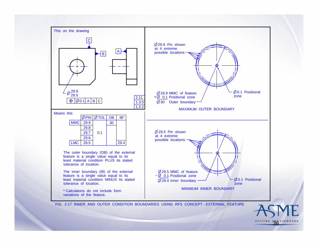
variations of the feature.* Calculaions do not include form
2.11
A
30.530.1
30.10.1
30
MMC of featurePositional zoneInner boundary
geometric tolerance.least material condition PLUS its statedfeature is a single value equal to itsThe outer boundary (OB) of the internal
stated geometric tolerance.maximum material condition MINUS itsfeature is a single value equal to itsThe inner boundary (IB) of the internal
30.130.230.330.430.5HOLE
MMC
LMCIBTOL
0.1
30
OB*30.6
MAXIMUM OUTER BOUNDARY
MINIMUM INNER BOUNDARY
0.1 Positionalzone
possible locationsat 4 extreme
30.1 Hole shown
–
30.5 Hole shownat 4 extremepossible locations
30.6
30.5––
Outer boundaryPositional zoneLMC of feature
0.1zone
0.1 Positional
0.1 A B C1.3.2
FIG. 2-14 INNER AND OUTER BOUNDARIES USING RFS CONCEPT - INTERNAL FEATURE
1.3.5
C
B

34
FIG. 2-15 VIRTUAL AND RESULTANT CONDITION BOUNDARIES USING MMC CONCEPT-EXTERNAL FEATURE
C
This on the drawing Means this
1.3.21.3.51.3.51
1.3.672.11
B A
29.929.5
M0.1 A B C
geometric tolerance.material condition MINUS its applicablefeature is a single value equal to its leastThe resultant condition (RC) of an external
applicable geometric tolerance.maximum material condition PLUS itsfeature is a constant value equal to itsThe virtual condition (VC) of the external
29.529.629.729.829.9PIN
LMC
MMCVCTOL
0.40.5
0.20.3
0.1
30
RC
29
29.90.1
30
MMC of featurePositional zone at MMCVirtual condition (Outer boundary)
RESULTANT CONDITION BOUNDARY
VIRTUAL CONDITION BOUNDARY
0.5 Positionalzone at LMC
LMC of featurePositional zone at LMCResultant condition (Inner boundary)
0.1 Positionalzone at MMC
possible locationsat 4 extreme
29.9 Pin shown
29.50.5
29
–
at 4 extremepossible locations
29.5 Pin shown
–
–

35
0.1 A B CL
This on the drawing Means this
1.3.21.3.5
1.3.672.11
1.3.5129.929.5
RESULTANT CONDITION BOUNDARY
VIRTUAL CONDITION BOUNDARY
0.5 Positionalzone at MMC
MMC of featurePositional zone at MMCResultant condition (Outer boundary)
29.50.1
29.4
0.1 Positionalzone at LMC
possible locationsat 4 extreme
29.5 Pin shown
LMC of featurePositional zone at LMCVirtual condition (Inner boundary)
29.90.5
30.4
–
+
applicable geometric tolerance.maximum material condition PLUS itsfeature is a single value equal to itsThe resultant condition (RC) of the external
applicable geometric tolerance.least material condition MINUS itsfeature is a constant value equal to itsThe virtual condition (VC) of the external
29.529.629.729.829.9PIN
LMC
MMCVCTOL
0.20.1
0.40.3
0.5
29.4
RC30.4
at 4 extremepossible locations
29.9 Pin shown
C
AB
FIG. 2-16 VIRTUAL AND RESULTANT CONDITION BOUNDARIES USING LMC CONCEPT-EXTERNAL FEATURE
36
A
29.929.5
tolerance of location.least material condition MINUS its statedfeature is a single value equal to itsThe inner boundary (IB) of the external
tolerance of location.least material condition PLUS its statedfeature is a single value equal to itsThe outer boundary (OB) of the external
29.529.629.729.829.9PIN
LMC
MMCOBTOL
0.1
IB*
29.4
29.90.1
30
MMC of featurePositional zoneOuter boundary
MINIMUM INNER BOUNDARY
MAXIMUM OUTER BOUNDARY
0.1 Positionalzone
possible locationsat 4 extreme
29.9 Pin shown
––
29.50.1
29.4
MMC of featurePositional zoneInner boundary
possible locationsat 4 extreme
29.5 Pin shown
–
30
CBA0.1
This on the drawing
variations of the feature.* Calculaions do not include form
0.1 Positionalzone
Means this
2.11
1.3.2
FIG. 2-17 INNER AND OUTER CONDITION BOUNDARIES USING RFS CONCEPT - EXTERNAL FEATURE
1.3.5
C
B

Deleted figuresFigure 2.14 Tolerancing an Angular Surface with a Basic Angle.
Figure 2.15 Specifying a Basic Diameter
37
38
Questions:
Answers represent the opinion of the respondent and do not represent
ASME.


Section 4Datum Reference Frames
Al Neumann
Section 4 - Work Group Leader

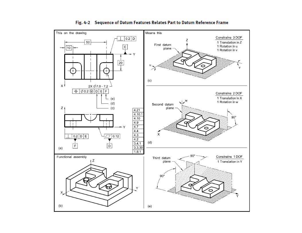
4.2 DEGREES OF FREEDOM
All parts have six degrees of freedom, three translational and three rotational, which may be constrained by datum feature references in a feature control frame. The three translational degrees of freedom are termed X, Y, and Z. The three rotational degrees of freedom are termed u, v, and w. See Figs. 4-1, 4-2, illustration (c); 4-2,illustration (d); and 4-2, illustration (e).

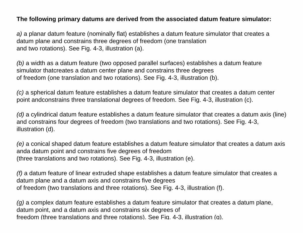
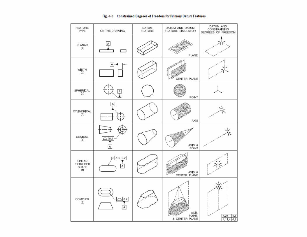
The following primary datums are derived from the associated datum feature simulator:
a) a planar datum feature (nominally flat) establishes a datum feature simulator that creates a datum plane and constrains three degrees of freedom (one translationand two rotations). See Fig. 4-3, illustration (a).
(b) a width as a datum feature (two opposed parallel surfaces) establishes a datum feature simulator thatcreates a datum center plane and constrains three degreesof freedom (one translation and two rotations). See Fig. 4-3, illustration (b).
(c) a spherical datum feature establishes a datum feature simulator that creates a datum center point andconstrains three translational degrees of freedom. See Fig. 4-3, illustration (c).
(d) a cylindrical datum feature establishes a datum feature simulator that creates a datum axis (line) and constrains four degrees of freedom (two translations and two rotations). See Fig. 4-3, illustration (d).
(e) a conical shaped datum feature establishes a datum feature simulator that creates a datum axis anda datum point and constrains five degrees of freedom(three translations and two rotations). See Fig. 4-3, illustration (e).
(f) a datum feature of linear extruded shape establishes a datum feature simulator that creates a datum plane and a datum axis and constrains five degreesof freedom (two translations and three rotations). See Fig. 4-3, illustration (f).
(g) a complex datum feature establishes a datum feature simulator that creates a datum plane, datum point, and a datum axis and constrains six degrees offreedom (three translations and three rotations). See Fig. 4-3, illustration (g).

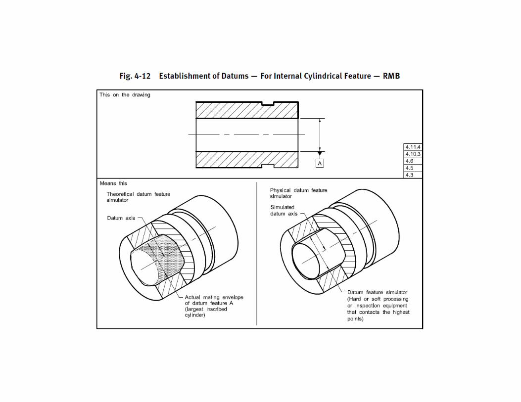
4.5 DATUM FEATURE SIMULATORA datum feature simulator, as defined in para. 1.3.17,shall be the inverse shape of the datum feature, unless otherwisespecified. See Figs. 4-10, 4-11, 4-12, 4-13, and 4-14.1.3.17 Datum Feature Simulatordatum feature simulator: encompasses two types: theoreticaland physical. See paras. 1.3.17.1 and 1.3.17.2.1.3.17.1 Datum Feature Simulator (Theoretical). datumfeature simulator (theoretical): the theoretically perfectboundary used to establish a datum from a specifieddatum feature.
1.3.17.2 Datum Feature Simulator (Physical). datumfeature simulator (physical): the physical boundary usedto establish a simulated datum from a specified datumfeature.NOTE: For example, a gage, fixture element, or digital data (suchas machine tables, surface plates, a mandrel, or mathematicalsimulation) —although not true planes — are of sufficient qualitythat the planes derived from them are used to establish simulateddatums. Physical datum feature simulators are used as the physicalembodiment of the theoretical datum feature simulators duringmanufacturing and inspection. See ASME Y14.43.

4.5.1 ExamplesA datum feature simulator may be one of the following:(a) a maximum material boundary (MMB)(b) a least material boundary (LMB)(c) an actual mating envelope(d) a minimum material envelope(e) a tangent plane(f) a datum target(s)(g) a mathematically defined contour
NOTE: Whenever the term “datum feature simulator” is used inthis Standard, it refers to the theoretical, unless specifically otherwiseindicated.


4.5.2 RequirementsDatum feature simulators shall have the followingrequirements:(a) perfect form.(b) basic orientation relative to one another for all thedatum references in a feature control frame.(c) basic location relative to other datum feature simulatorsfor all the datum references in a feature controlframe, unless a translation modifier or movable datumtarget symbol is specified. See Figs. 4-9, 4-19, and 4-32,illustration (a).(d) movable location when the translation modifieror the movable datum target symbol is specified. SeeFigs. 4-19, 4-32, illustration (b), and 4-49.(e) fixed at the designated size, when MMB or LMB isspecified.(f) adjustable in size, when the datum feature appliesat RMB.

4.6 THEORETICAL AND PHYSICAL APPLICATIONOF DATUM FEATURE SIMULATORS
Theoretical datum feature simulators formerly called True Geometric Counterpart (TGC)

4.9 DATUM FEATURE CONTROLSGeometric tolerances related to a datum reference frame do not take into account any variations in form, orientation, or location of the datum features. Datum features shall be controlled directly by applying appropriate geometric tolerances or indirectly by dimensions such as the size of a primary datum feature of size. This in turn makes it possible to calculate the datum feature simulator boundaries of each datum feature in a datum reference frame. The relationships between datum features to be considered are the
(a) form of the primary datum feature(s) (see Figs. 4-2 and 4-5) and/or the location between features in a pattern used to establish the primary datum. See Figs. 4-24and 4-25.(b) secondary datum features’ orientation and/or location as applicable, to higher precedence datums. See Figs. 4-2, 4-5, 4-26, and 4-30.(c) tertiary datum features’ orientation and/or location to higher precedence datums as applicable. See Figs. 4-2 and 4-5.


4.11.2 Irregularities on Datum FeaturesIf irregularities on a datum feature are such that the part is unstable (that is, it rocks) when brought into contact with the corresponding datum feature simulator, the default stabilization procedure is per the candidate datum set as outlined in ASME Y14.5.1M. If a different procedure is desired (Chebychev, least squares,
4.11.3 Effect of Material Boundary Modifiers Applied to Datum Feature ReferencesMMB, LMB, and RMB conditions may be applied/implied to any datum feature reference
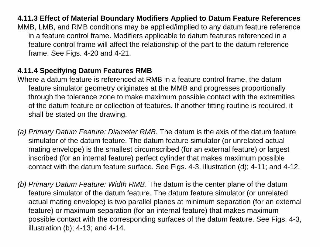
in a feature control frame. Modifiers applicable to datum features referenced in a feature control frame will affect the relationship of the part to the datum reference frame. See Figs. 4-20 and 4-21.
4.11.4 Specifying Datum Features RMBWhere a datum feature is referenced at RMB in a feature control frame, the datum
feature simulator geometry originates at the MMB and progresses proportionally through the tolerance zone to make maximum possible contact with the extremities of the datum feature or collection of features. If another fitting routine is required, it shall be stated on the drawing.
(a) Primary Datum Feature: Diameter RMB. The datum is the axis of the datum feature simulator of the datum feature. The datum feature simulator (or unrelated actual mating envelope) is the smallest circumscribed (for an external feature) or largest inscribed (for an internal feature) perfect cylinder that makes maximum possible contact with the datum feature surface. See Figs. 4-3, illustration (d); 4-11; and 4-12.
(b) Primary Datum Feature: Width RMB. The datum is the center plane of the datum feature simulator of the datum feature. The datum feature simulator (or unrelatedactual mating envelope) is two parallel planes at minimum separation (for an external feature) or maximum separation (for an internal feature) that makes maximum possible contact with the corresponding surfaces of the datum feature. See Figs. 4-3, illustration (b); 4-13; and 4-14.


4.11.5 Specifying Datum Features at MMBWhere MMB is applied to a datum feature referenced in a feature control frame it establishes the datum feature simulator of the appropriate boundary. The appropriateboundary is determined by its collective effects of size, and any applicable geometric tolerances relative to any higher precedence datums. As a practical example, where a datum feature is applied on an MMB basis, machine and gaging elements in the processing equipment that remain constant may be used to simulate a datum feature simulator of the feature and to establish the simulated datum. To determine the applicable boundary, see para 4.11.6
4.11.6 Determining Size of Datum Feature Simulators at MMBAn analysis of geometric tolerances applied to a datum feature is necessary in determining the size of its datum feature simulator. A feature of size or pattern of features of size serving as a datum feature may have several MMB. These include the MMC of a datum feature of size or the collective effects of MMC and geometrictolerances. Datum feature precedence shall be respected, except in the case of a customized datum reference frame. See para. 4.22. Therefore, the appropriate MMB for determining the size of the datum feature simulator for an
(a) internal datum feature of size is the largest MMB that the datum feature(s) of size will contain while respecting the datum feature precedence.
(b) external feature of size is the smallest MMB that will contain the datum feature(s) of size while respecting the datum feature precedence. See Fig. 4-16 for examples of calculating the size of MMB.
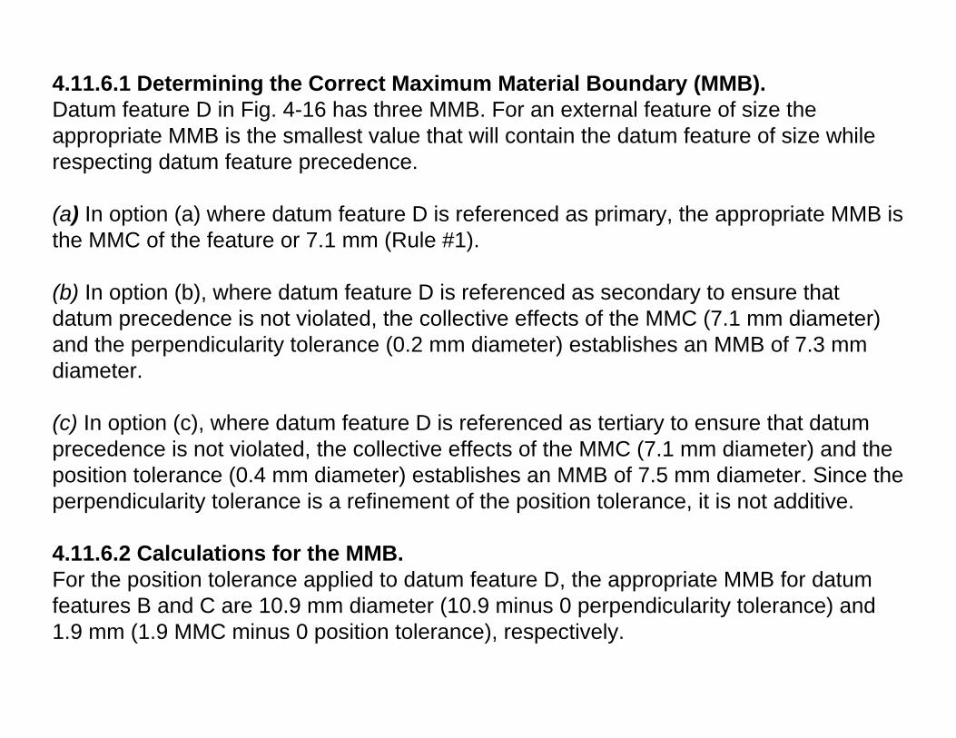
4.11.6.1 Determining the Correct Maximum Material Boundary (MMB). Datum feature D in Fig. 4-16 has three MMB. For an external feature of size the appropriate MMB is the smallest value that will contain the datum feature of size while respecting datum feature precedence.
(a) In option (a) where datum feature D is referenced as primary, the appropriate MMB is the MMC of the feature or 7.1 mm (Rule #1).
(b) In option (b), where datum feature D is referenced as secondary to ensure that datum precedence is not violated, the collective effects of the MMC (7.1 mm diameter) and the perpendicularity tolerance (0.2 mm diameter) establishes an MMB of 7.3 mm diameter.
(c) In option (c), where datum feature D is referenced as tertiary to ensure that datum precedence is not violated, the collective effects of the MMC (7.1 mm diameter) and the position tolerance (0.4 mm diameter) establishes an MMB of 7.5 mm diameter. Since the perpendicularity tolerance is a refinement of the position tolerance, it is not additive.
4.11.6.2 Calculations for the MMB. For the position tolerance applied to datum feature D, the appropriate MMB for datum features B and C are 10.9 mm diameter (10.9 minus 0 perpendicularity tolerance) and 1.9 mm (1.9 MMC minus 0 position tolerance), respectively.


4.11.6.3 Clarifying Applicable MMB. In cases where the boundary is not clear, or another boundary is desired, the value of the boundary shall be stated, enclosed in brackets, following the applicable datum feature reference and any modifier in the feature control frame. The term “BSC” or “BASIC” may be used to indicate that the datum feature simulator is located at the basic location of the datum feature. See Fig. 4-31, illustration (b).EXAMPLE:
Where an MMB equal to MMC is the design requirement for a given datum feature, a zero geometric tolerance at MMC is specified to the datum feature as shown on datum features B and C in Fig. 4-16. See para. 7.3.4 and Fig. 6-14.

4.11.7 Specifying Datum Features at LMBWhere LMB is applied to a datum feature referenced in a feature control frame it establishes the datum feature simulator at the appropriate boundary. The appropriateboundary is determined by its collective effects of size, and any applicable geometric tolerances relative to any higher precedence datums. See para. 2.11 and Fig. 4-17. This example illustrates both secondary and tertiary datum features specified at LMB and simulated at LMB.
4.11.8 Multiple LMBsA feature or pattern of features serving as a datum feature may have several LMB. These include the LMC of a feature or the collective effects of LMC and geometric tolerances. Datum precedence may not be violated, except in the case of a customized datum reference frame. In cases where the boundary is not clear, or another boundary is desired, the value of the boundary shall be stated following the applicable datum featurereference any modifier in the feature control frame.EXAMPLE:

4.11.9 Datum Feature Shift/DisplacementMMB or LMB modifiers applied to the datum feature reference will allow the datum feature to shift/displace from the boundary established by the datum feature simulatorin an amount that is equal to the difference between the applicable (unrelated or related) actual mating envelope for MMB, actual minimum material envelope for LMB, or surface of the feature and the datum feature simulator. The datum reference frame is established from the datum feature simulator and not the datum features. See Fig. 4-17 for LMB, Figs. 4-18 and 4-24, datum feature B in Fig. 4-26 for MMB, and Fig. 4-30, illustration (b) for the surface. The datum feature shift/displacement shall always be limited or constrained by the datum feature simulator. If the datum feature simulator geometry is such that it does not fully limit or constrain the feature such as rotating away from the datum feature simulator beyond the established boundary limits, as shown inFig. 4-31, illustration (c), then the feature must remain in contact with the datum feature simulator, and datum shift or displacement is not allowed. See para. 4.16.7 anddatum feature A in Fig. 4-28.


4.11.10 Translation ModifierWhere it is necessary to indicate that the basic location of the datum feature simulator is unlocked and the datum feature simulator is able to translate within the specified geometric tolerance to fully engage the feature, the translation modifier is added to the feature control frame following the datum feature reference and any other applicable modifiers. See Figs. 4-19 and 4-32, illustration (b), and para. 3.3.26. When the translation modifier is applicable and the direction of movement is not clear, movement requirements shall be specified.


4.11.11 Effects of Datum Precedence and Datum Feature Material Boundary ConditionsWhere datums are specified in an order of precedence, the material boundary condition at which the datum feature applies must be determined. The effect of its material boundary condition and order of precedence should be considered relative to fit and function of the part. Figures 4-20 and 4-21 illustrate a part with a pattern of holes located in relation to diameter A and surface B. As indicated by asterisks, datum


4.12 MULTIPLE DATUM FEATURESWhere more than one datum feature is used to establisha datum feature simulator for a single datum, the appropriate datum feature reference letters and associated modifiers, separated by a dash, are entered in one compartment of the feature control frame. See para. 3.4.2 andFig. 4-22. Since the datum features have equal importance, datum feature reference letters may be entered in any order within this compartment. Where the intent is clear, a datum feature reference letter may be used to define the multiple surfaces as a single datum feature.

4.12.1 Simulation of a Single Datum PlaneFigure 4-23 is an example of a single datum plane simulated, as explained in para. 4.11.1, by coinciding with the datum feature simulator that simultaneouslycontacts the high points of two surfaces. Identification of two features to establish a single datum plane may be required where separation of the features is caused by an obstruction, such as in Fig. 4-23, or by a comparable opening (e.g., a slot). For controlling coplanarity of these surfaces, see Fig. 4-23 and para. 8.4.1.1. A single datum feature symbol may also be used to indicate that offset surfaces establish a single datum.

4.12.4 Pattern of Features of Size at RMBWhere RMB is applied in a feature control frame to multiple datum features of size used to establish a single datum, the datum feature simulator of each feature shall be fixed in a location relative to one another. The datum feature simulators shall expand or contract simultaneously from their MMB to their LMB until the datum feature simulators make maximum possible contact with the extremities of the datum feature(s). See Fig. 4-25.

4.13 MATHEMATICALLY DEFINED SURFACEIt is sometimes necessary to identify a compound curve or a contoured surface as a datum feature. A mathematically defined feature shall be defined within a three-dimensional coordinate system. Where such a feature is specified as a datum feature, its datum feature simulator (derived from the math data) is used in establishing the datum reference frame. Aligning the high points of the datum feature with its datum feature simulator restricts movement of the part to the datum reference frame. Where the datum feature alone will not adequately restrict the required degrees of freedom ofthe part, additional datum features will be required. See Fig. 4-28.


4.14 MULTIPLE DATUM REFERENCE FRAMESMore than one datum reference frame may be necessary for certain parts, depending upon functional requirements. Where more than one datum reference frame is used andit is necessary to determine the relationships and calculate boundaries between the reference frames, the relationship between the datum reference frames shall be specified. In Fig. 4-4, datum features A and B establish one datum reference frame, while datum features C and D establish a different datum reference frame.


4.15 FUNCTIONAL DATUM FEATURESOnly the required datum features should be referenced in feature control frames when specifying geometric tolerances. An understanding of the geometric controlprovided by these tolerances (as explained in Sections 5 through 9) is necessary to determine effectively the number of datum feature references required for a givenapplication. The functional requirements of the design should be the basis for selecting the related datum features to be referenced in the feature control frame. Figures 4-36 through 4-38 illustrate parts in an assembly where geometric tolerances are specified, each having the required number of datum feature references.


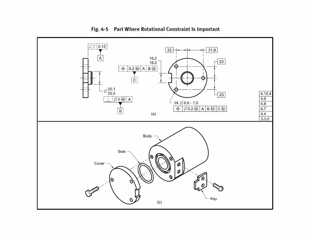
4.16 ROTATIONAL CONSTRAINT ABOUT A DATUM AXIS OR POINTWhere a datum reference frame is established from a primary or secondary datum axis or point, a lower precedence datum feature surface or feature of size may be used to constrain rotation. See para. 4.10.4. Depending on functional requirements, there are many ways to constrain the rotational degrees of freedom about thehigher precedence datum. Figures 4-8 and 4-29 through 4-32 illustrate the development of a datum reference frame based on the principles outlined in the datum feature simulator requirements. In these figures, datumfeature A establishes an axis. The lower precedence datum feature B is located (positioned or profiled) to datum feature A and is then used to orient the rotational degrees of freedom to establish the datum referenceframe that is used to locate the two 6-mm diameter holes. Depending on functional requirements, this lower precedence datum feature may apply at RMB or be modified to apply at MMB or LMB. The datum reference frame is established from the datum feature simulators and not the datum features.

4.16.1 Contoured Datum Feature at RMB Constraining a Rotational Degree of FreedomIn Fig. 4-29, illustration (a), datum feature B applies at RMB. This requires the datum feature simulator geometry to originate at the MMB of R14.9 mm and progress through the profile tolerance zone toward the LMB of R15.1 mm until it makes maximum contact with datum feature B and constrains the rotational degree of freedom of the part around the axis of the datum feature simulator from datum feature A.
4.16.2 Contoured Datum Feature at MMB Constraining a Rotational Degree of FreedomIn Fig. 4-29, illustration (b), datum feature B is modified to apply at MMB. This requires the datum feature simulator to be fixed at the MMB of R14.9 mm and thus orients the two planes that originate at the axis of the datum feature simulator of datum feature A. Datum feature B may rotate within the confines created by its departure from MMB and might not remain in contact with the datum feature simulator.


4.16.3 Planar Datum Feature at RMB Constraining a Rotational Degree of FreedomIn Fig. 4-30, illustration (a), datum feature B applies at RMB. This requires the datum feature simulator geometry to originate at MMB of 15.1 mm and progress through the profile tolerance zone toward the LMB of 14.9 mm until it makes maximum contact with datum feature B and constrains the rotational degree of freedom of the part around the axis of the datum feature simulator of datum feature A.
4.16.4 Planar Datum Feature at MMB Constraining a Rotational Degree of FreedomIn Fig. 4-30, illustration (b), datum feature B is modified to apply at MMB. This requires the datum feature simulator to be fixed at the MMB of 15.1 mm and thus orients the two planes that originate at the axis of the datum feature simulator of datum feature A. Datum feature B may rotate within the confines created by its departure from MMB and might not remain in contact with the datum feature simulator.


4.16.5 Offset Planar Datum Feature at RMB Constraining a Rotational Degree of FreedomIn Fig. 4-31, illustration (a), datum feature B is offset relative to datum axis A and applies at RMB. This requires the datum feature simulator geometry to originate at MMB of 5.1 mm and progress through the profile tolerance zone toward the LMB of 4.9 mm until it makes maximum contact with datum feature B (possible two point contact) and constrains the rotational degree of freedom of the two planes of the datum reference frame around the axis of the true geometric counterpart of datum feature A.4.16.6 Offset Planar Datum Feature Set at Basic Constraining a Rotational Degree of FreedomIn Fig. 4-31, illustration (b), datum feature B is offset 5 mm relative to datum axis A. RMB does not apply as it is overridden in the feature control frame for the two holesby the abbreviation BSC in brackets following the reference to datum feature B. See para. 4.11.6.3. This requires the datum feature simulator to be fixed at 5 mm basic andconstrains the rotational degree of freedom of the two planes of the datum reference frame around the axis of the datum feature simulator from datum feature A.4.16.7 Offset Planar Datum Feature at MMB Constraining a Rotational Degree of FreedomIn Fig. 4-31, illustration (c), datum feature B is offset relative to datum axis A and modified to apply at MMB. This requires the datum feature simulator to be fixed at the MMB of 5.1 mm and constrains the rotational degree of freedom of the two planes of the datum reference frame that originate at the datum feature simulator of datum feature A. Where the datum feature simulator and the higher precedence datum axis do not limitrotation in both directions about the datum axis, the datum feature must always contact the datum feature simulator.

4.16.8 Datum Feature of Size at RMB Constraining aRotational Degree of FreedomIn Fig. 4-32, illustration (a), datum feature B appliesat RMB and is located relative to datum axis A. Thisrequires the center plane of the datum feature simulatorgeometry to be fixed at the basic 5 mm dimension andthe datum feature simulator geometry to expand untilit makes maximum contact with datum feature B. Thisconstrains the rotational degree of freedom of the twoplanes of the datum reference frame around the axis ofthe datum feature simulator of datum feature A.4.16.9 Datum Feature of Size at RMB With TranslationModifier Constraining Rotational Degrees ofFreedomIn Fig. 4-32, illustration (b), datum feature B appliesat RMB with a translation modifier. This allows thecenter plane of the datum feature simulator to translatewhile maintaining its orientation to higher precedencedatums. The parallel planes of the datum featuresimulator expand to make maximum contact with thedatum feature.


4.19 SIMULTANEOUS REQUIREMENTSA simultaneous requirement is where two or more geometric tolerances apply as a single pattern or part requirement. A simultaneous requirement applies to position and profile tolerances that are located by basic dimensions, related to common datum features referenced in the same order of precedence at the same boundary conditions. In a simultaneous requirement there is no translation or rotation between the datumreference frames of the included geometric tolerances, thus creating a single pattern. Figures 4-39 and 4-40 show examples of simultaneous requirements. If such interrelationship is not required, a notation such as SEP REQT is placed adjacent to each applicable feature control frame. See Figs. 4-41 and 7-54 and para. 7.5.4.2. This principle does not apply to the lower segments of composite feature control frames. See para. 7.5.4.2. If a simultaneous requirement is desired for the lower segments of two ormore composite feature control frames, a notation such as SIM REQT shall be placed adjacent to each applicable lower segment of the feature control frames.


4.20 RESTRAINED CONDITIONUnless otherwise specified, all tolerances apply in a free-state condition. In some cases, it may be desirable to restrain a part on its datum features to simulate their function or interaction with other features or parts. To invoke a restrained condition, a note is specified or referenced on the drawing defining the specific requirements. See Fig. 4-42. This figure illustrates a part that should be restrained until sufficient reinforcement is added to retain its design shape. In this illustration, the restraint must be per a document referenced on the drawing. In a restrained application, it is permissible to use as many datum targets as necessary to establish the datum features.

4.21 DATUM REFERENCE FRAME IDENTIFICATIONWhere a datum reference frame has been properly established and it is considered necessary to illustrate the axes of a datum reference frame on the drawing, the axes or center planes may be labeled to determine the translational degrees of freedom X, Y, and Z. See Figs. 4-2, 4-7, 4-8, and 4-54. Where multiple datum reference frames exist, and it is desirable to label the axes (X, Y, and Z), any labeled axes shall include a reference to the associated datum reference frame. In Fig. 4-43 the X, Y, and Z axes for the three datum reference frames are identified by the notation [A, B, C], [A, B, D], and[A, B, E]. These labels represent the datum features (without modifiers) for each datum reference frame and follow the X, Y, and Z identification letters.


Section 4Datum Reference Frames
Don Day
President, Tec-Ease, Inc.
Section 4 Work Group, Member
ASME Y14.8, Chair

• Irregular features of Size as Datum Features• Customizing the Datum Reference Frame• Movable Datum Targets

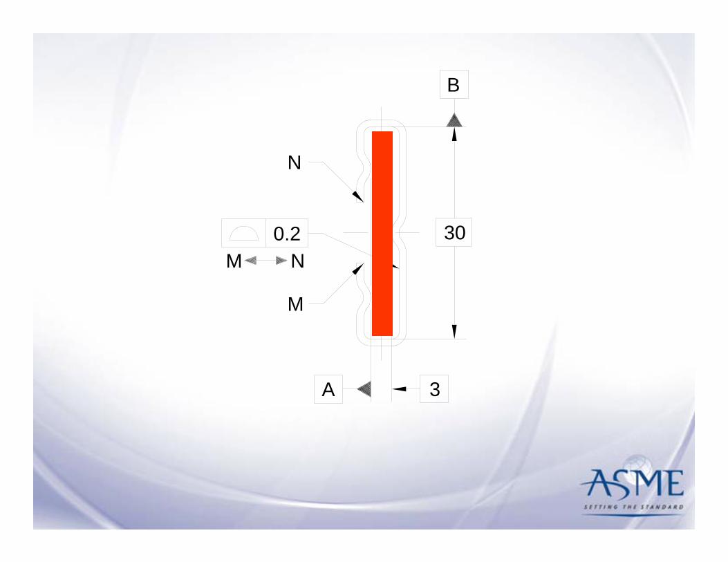
Irregular Features of Size as Datum Features
Features and collections of features that act like features of
size, but Rule #1 does not apply.

Regular Features of SizeFrom ASME Y14.5M-1994:• One cylindrical or spherical surface, or a set of two
opposed elements or opposed parallel surfaces, associated with a size dimension.– Sphere– Cylinder– Width (slot or tab)
• Rule #1– The limits of size control the form of the feature– Feature had to be within the actual local size at each cross
section
Regular Features of Size
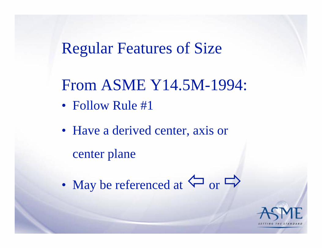
From ASME Y14.5M-1994:• Follow Rule #1
• Have a derived center, axis or
center plane
• May be referenced at or

1.3.32.2 Irregular Feature of Size.• Follow Rule #1
• May have a derived center, axis or
center plane
• May be referenced at or

FIG. 4-35 DATUM POSSIBILITIES FROM THREE PINS FOR AN IRREGULAR FEATURE OF SIZE
3.3.2
(c) Distance inside pins
(a) Inscribed cylinder (b) Circumscribed cylinder
(d) Distance outside pins
Disk with 3 inserted pinscan establish different datumfeatures as illustrated below.
A
A
AA
4.17

(c) Distance inside pins
(a) Inscribed cylinder (b) Circumscribed cylinder
(d) Distance outside pins
A
A
AA
3.3.2
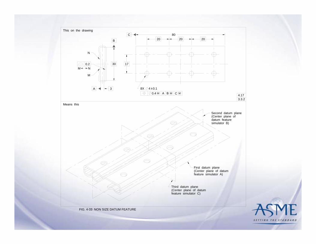
FIG. 4-33 NON SIZE DATUM FEATURE
8X 4 0.1±A 3C0.4 M A B M M
30
B
17
20 20 2080C
First datum plane
(Center plane ofSecond datum plane
Third datum plane
This on the drawing
Means this
0.2
M
N
M N
datum feature
(Center plane of datumfeature simulator A)
(Center plane of datumfeature simulator C)
4.17
simulator B)
A 3
30
B
0.2
M
N
M N

4.17
FIG. 4-34 COAXIAL IRREGULAR NON SIZE DATUM FEATURE
0.5
Datum feature A
This on the drawing
Means this
A
3X R43X
Datum axis A
B
C
A B C
0.1
X Y
X Y
0.1
Third datum plane
First and seconddatum planes
3X 200.3 B
A

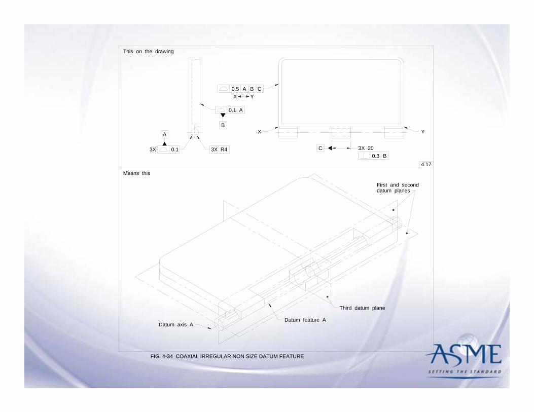
4.17
FIG. 4-34 COAXIAL IRREGULAR NON SIZE DATUM FEATURE
0.5
Datum feature A
This on the drawing
Means this
A
3X R43X
Datum axis A
B
C
A B C
0.1
X Y
X Y
0.1
Third datum plane
First and seconddatum planes
3X 200.3 B
A

0.5
the drawing
A
3X R43X
B
C
A B C
0.1
X Y
X Y
0.1
3X 200.3 B
A

4.17
FIG. 4-34 COAXIAL IRREGULAR NON SIZE DATUM FEATURE
0.5
Datum feature A
This on the drawing
Means this
A
3X R43X
Datum axis A
B
C
A B C
0.1
X Y
X Y
0.1
Third datum plane
First and seconddatum planes
3X 200.3 B
A
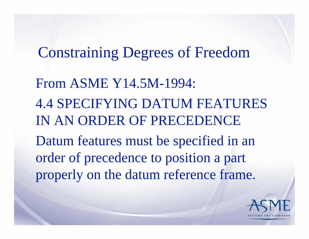
Constraining Degrees of Freedom
From ASME Y14.5M-1994:4.4 SPECIFYING DATUM FEATURES IN AN ORDER OF PRECEDENCEDatum features must be specified in an order of precedence to position a part properly on the datum reference frame.
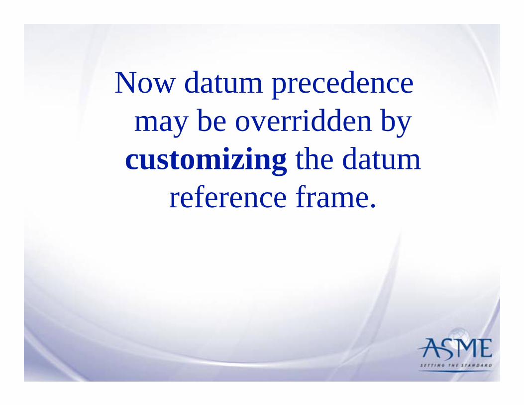
Now datum precedence may be overridden by
customizing the datum reference frame.

FIG. 4-43 DATUM REFERENCE FRAME IDENTIFICATION
19 0.2
4.21
x[A,B,D]
13.8
13.4
A
4
3.8
3.1 0.20.5 A B E
±
33.9
0.20.5 A B D
±
y[A,B,D]
y[A,B,E]
x[A,B,E]
y[A,B,C]y[A,B,E]
30.8
3.1
z[A,B,E]
22°
0.1 A B C
0 M A B0 M A
D
0.1 A B C
E
3.02 ±0.1
CB
UOS ALL SURFACES0.8 A B C
±
y[A,B,C]
x[A,B,C] z[A,B,C]

FIG. 4-43 DATUM REFERENCE FRAME IDENTIFICATION
19 0.2
4.21
x[A,B,D]
13.8
13.4
A
4
3.8
3.1 0.20.5 A B E
±
33.9
0.20.5 A B D
±
y[A,B,D]
y[A,B,E]
x[A,B,E]
y[A,B,C]y[A,B,E]
30.8
3.1
z[A,B,E]
22°
0.1 A B C
0 M A B0 M A
D
0.1 A B C
E
3.02 ±0.1
CB
UOS ALL SURFACES0.8 A B C
±
y[A,B,C]
x[A,B,C] z[A,B,C]
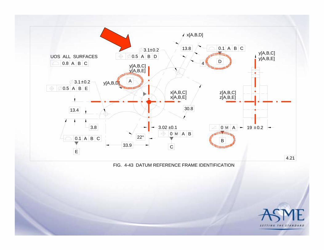
FIG. 4-43 DATUM REFERENCE FRAME IDENTIFICATION
19 0.2
4.21
x[A,B,D]
13.8
13.4
A
4
3.8
3.1 0.20.5 A B E
±
33.9
0.20.5 A B D
±
y[A,B,D]
y[A,B,E]
x[A,B,E]
y[A,B,C]y[A,B,E]
30.8
3.1
z[A,B,E]
22°
0.1 A B C
0 M A B0 M A
D
0.1 A B C
E
3.02 ±0.1
CB
UOS ALL SURFACES0.8 A B C
±
y[A,B,C]
x[A,B,C] z[A,B,C]

4.22
FIG. 4-44 CONICAL DATUM FEATURE
This on the drawing
Means this
73
6 0.1±0.2 A
Datum axis
YZ
Y
4.23
Y
Z
X
0.02
A
Datum planesOrigin ofdimensions
yv
u
x
z
w
X
4.2☯ [u,v,x,y,z]

4.22
FIG. 4-45 CONICAL DATUM FEATURE
This on the drawing
Means this
246 0.1
AB
±0.2 A [x,y,u,v] B
Datum axis
[z]
Y
Z
0.02
A0.12
X
Y
4.23
Y
Z
XDatum planes
Origin ofdimensions
yv
u
x
z
w
☯ [u,v,x,y,z]

FIG. 4-46 CUSTOMIZED DATUM REFERENCE FRAME
This on the drawing
Means this
50
6 0.1
A
±0.5 A [z,u,v] B [x,y]
Y
X
C [w]3X
2X 10
34.6
15
81
M
0.2 A
8 0.1±0.5 A
12
0.2
yv
u
x
z
w
Z
B
C
[z,u,v] B [x,y]
Origin of measurement
Second and thirddatum planes
Y
X
Z
Y
4.224.23

50
6 0.1
A
±0.5 A [z,u,v] B [x,y]
Y
X
C [w]3X
2X 10
34.6
15
81
M
0.2 A
8 0.1±0.5 A
12
0.2
Z
B
C
[z,u,v] B [x,y]
Y

Movable
Datum
Target

From the ASME Y14.5M-1994 standard

From the ASME Y14.8M-1996 standard

From the ASME Y14.8M-1996 standard

From the ASME Y14.8M-1996 standard

4.24.4
FIG. 4-47 APPLICATIONS OF MOVABLE DATUMS
2X 152X 45°
40 100
B2
38
6.3 - 6.44XCBA0.1
10
5
20
4.24.1
M
2X 45°
9
B1
B1 B2
A1 A2
A1
A2A3
A3
C2
C1
C1 C2
4.24.5x
x
z
y
3.3.27
4.24.64.24.9
Fig. 4-47 from the ASME Y14.5-2009 standard.

Fig. 4-49 from the ASME Y14.5-2009
standard.


Section 5Tolerances of Form
Dr. Don W. Shepherd
Shepherd Industries

Don Shepherd Section 5 Form
Location of Form Tolerances Section
Form tolerances were formerly in Section 6 with profile, orientation, and runout. To better guide the user of the Standard in the application of geometric dimensioning and tolerancing, form tolerances now are in a separate section.

Straightness of a Center Plane
Straightness of a center plane has been revised to flatness of a center plane to better reflect that it is a three-dimensional control, even though it is the same principle as in the previous edition of the Standard.
Don Shepherd Section 5 Form

Flatness of a derived median plane - RFS
FIG. 5-8 SPECIFYING FLATNESS OF A DERIVED MEDIAN
This on the drawing
16.0015.89 (16h11)
Means this5.4.2.1
16.00
0.04 wide tolerance zone16.04 outer boundary
0.04
element of the surface must be within the limits
The derived median plane of the feature's actuallocal size must lie between two parallel planes0.04 apart, regardless of the feature size. Each
of size.
PLANE - RFSREV A - 2009-04-27

Flatness of a derived median plane at MMC
FIG. 5-9 SPECIFYING FLATNESS OF A DERIVED MEDIAN PLANE AT MMC
This on the drawing
16.0015.89 (16h11)
Means this5.4.2.1
16.04 virtual condition
Featuresize
Parallel planestolerance allowed
16.0015.9915.98
15.9015.89
0.040.050.06
0.140.15
Acceptance boundary
16.00
16.04
16.04
16.000.04
(a)
(b)
16.04
15.890.15
(c)
The maximum thickness of the part with perfectform is shown in a simulated boundary with a
with the part at maximum thickness (16.00), thesimulated boundary will accept the part with up to0.04 variation in flatness;
with the part at minimum thickness (15.89), thesimulated boundary will accept the part with up to0.15 variation in flatness.
(a)
Meanings:
(b)
(c)
0.04
The derived median plane of the feature actual localsizes must lie between two parallel planes 0.04 apartat MMC. As each actual local size departs from MMC,an increase in the local width of the tolerance zoneis allowed which is equal to the amount of suchdeparture. Each element of the surface must be withinthe specified limit of size.
M
16.04 wide slot;


Section 6Tolerances of Orientation
Dr. Don W. Shepherd
Shepherd Industries

Don Shepherd Section 6 Orientation
Location of Orientation Tolerances Section
Orientation tolerances were formerly in Section 6 with form, profile, and runout. To better guide the user of the Standard in the application of geometric dimensioning and tolerancing, orientation tolerances now are in a separate section.

Don Shepherd Section 6 Orientation
Definitions
The definitions of Angularity, Parallelism, and Perpendicularity are unchanged from ASME Y14.5M-1994. In that revision the description of the three orientation tolerances and their tolerance zones was repeated for each of the three types of tolerance. The only difference between the three descriptions was the terms angularity, parallelism, or perpendicularity. In this revision the description of the tolerances and their tolerance zones is only stated one time and applies to all three orientation tolerances.

Orientation Definition as Condensed
Don Shepherd Section 6 Orientation

Don Shepherd Section 6 Orientation
Angularity Symbol
The use of the angularity symbol meaning orientation is introduced as an alternative practice to using perpendicularity or parallelism.

Specifying Orientation for a plane surface relative to two datums
6.4
FIG. 6-4 SPECIFYING ORIENTATION FOR A PLANE SURFACE RELATIVE TO TWO DATUMS
A
BA0.12
This on the drawing
Means this
B
Datum plane B(Secondary)
Datum plane A(Primary)
0.12
0.120.12
0.12 BA
Alternative practiceas referenced in para 6.6
The surface must be between two parallelplanes 0.12 apart which are perpendicularto datum plane A. Datum feature B isinvoked to constrain an additional rotationaldegree of freedom of the datum reference
6.4.26.6
frame.

Section 7Tolerances Of Location
Bruce A. Wilson10/8/2009

New Section Location
• Tolerances of position were formerly in Section 5. In order to better guide the user of the Standard in the application of geometric dimensioning and tolerancing, tolerances of position have been moved to the new Section 7. (A9.1)

Reorganized Content
• Tolerances of position have been reformatted so the material flows from the basic to more complex principles. (A9.2)– 7.3 Positional Tolerancing Fundamentals: I– 7.4 Positional Tolerancing Fundamentals: II– 7.5 Pattern Location– 7.6 Coaxial Feature Controls– 7.7 Tolerancing For Symmetrical Relationships

Position Between Features and Position To Datums
• Para. 7.2 defines positional tolerances to include their relationship to other features and relative to datums. (A9.3)
• This does not say that implied datums are allowed.
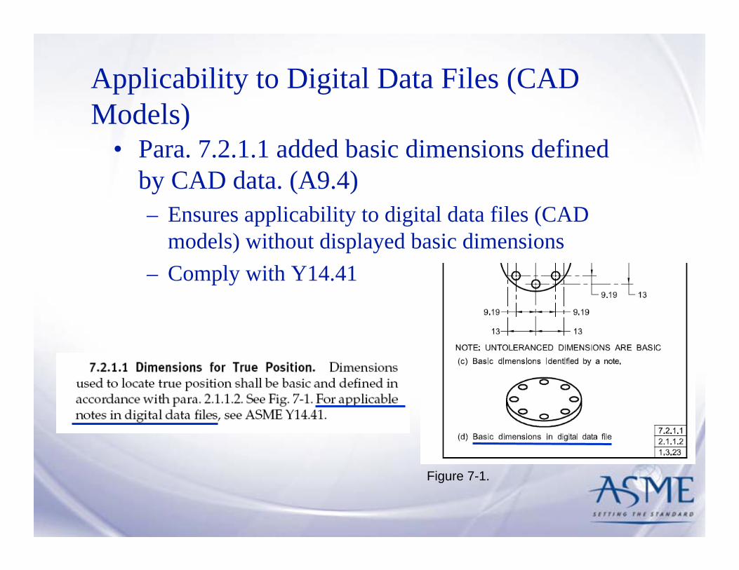
Applicability to Digital Data Files (CAD Models)
• Para. 7.2.1.1 added basic dimensions defined by CAD data. (A9.4)– Ensures applicability to digital data files (CAD
models) without displayed basic dimensions– Comply with Y14.41
Figure 7-1.
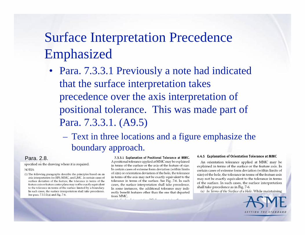
Surface Interpretation Precedence Emphasized• Para. 7.3.3.1 Previously a note had indicated
that the surface interpretation takes precedence over the axis interpretation of positional tolerance. This was made part of Para. 7.3.3.1. (A9.5)– Text in three locations and a figure emphasize the
boundary approach.Para. 2.8.
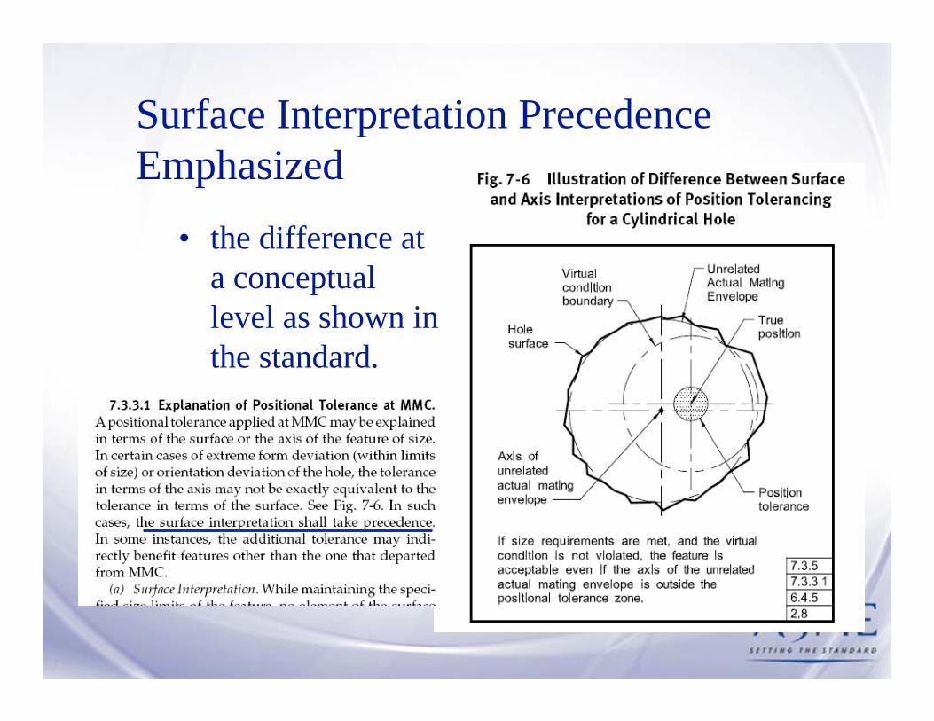
Surface Interpretation Precedence Emphasized
• the difference at a conceptual level as shown in the standard.
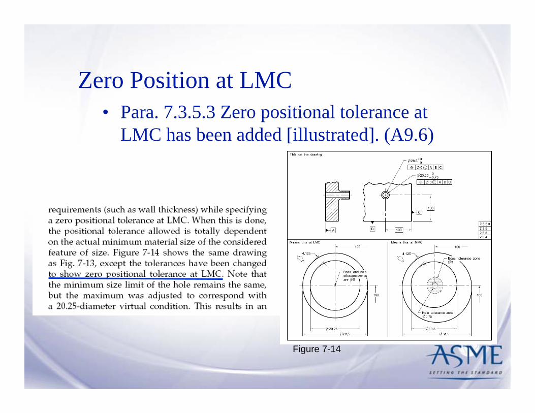
Zero Position at LMC
Figure 7-14
• Para. 7.3.5.3 Zero positional tolerance at LMC has been added [illustrated]. (A9.6)

Degrees of Freedom Terminology
• Effects of datum references in positional tolerances explained in degrees of freedom. (A9.7) – Degrees of freedom explain the tolerance
zone framework relationship to the datum reference frame
– Separates terminology for constraints (translation and rotations) on the framework from the terminology for the toleranced features (location and orientation)

Degrees of Freedom Terminology & Variation
Figure 7.5.1
• Effects of datum references in positional tolerances explained in degrees of freedom. (A9.7)

MMB Departure Effects on Position• Para. 7.3.6.2.2 Effects on position
tolerances caused by datum feature departure from MMB explained. (A9.8)– Relative movement
between the datumfeatures and the datums
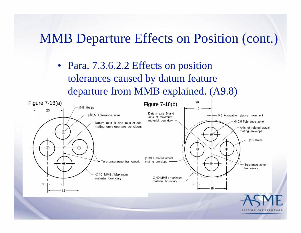
MMB Departure Effects on Position (cont.)
Figure 7-18(a) Figure 7-18(b)
• Para. 7.3.6.2.2 Effects on position tolerances caused by datum feature departure from MMB explained. (A9.8)

Repetitive Patterns• Para. 7.4.8 Positional tolerances on
repetitive patterns of features. (A9.9)– Expanded explanation

Simplified Figures - Repetition Minimized
• Sequential figures for composite positional tolerances were simplified so that each figure contains only the information to build on the previously shown figure. This reduced the amount of information that was repeated and makes finding the relevant information much easier. (A9.10)– 1994 repeated the entire series of figure segments for
each explanation– 2009 relies on the previous figure so that only the
relevant information is shown• Figure 7-38(a) through (f) develops the complete set of
requirements• Figure 7-39(a) builds on 7-38
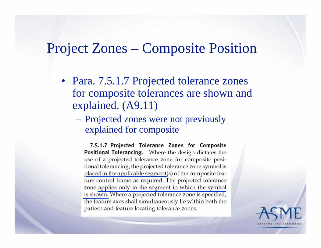
Project Zones – Composite Position
• Para. 7.5.1.7 Projected tolerance zones for composite tolerances are shown and explained. (A9.11)– Projected zones were not previously
explained for composite
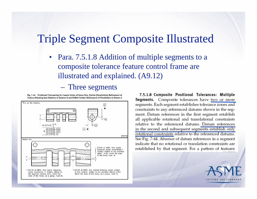
Triple Segment Composite Illustrated • Para. 7.5.1.8 Addition of multiple segments to a
composite tolerance feature control frame are illustrated and explained. (A9.12)– Three segments

Position Without Datum Feature References• Para. 7.6.2.3 Position tolerance is shown without a
datum reference to control coaxial features. (A9.13)– The pattern of features serves as a datum feature – probably the
primary datum feature for other tolerances. – Assumed or implied datum feature references not permitted
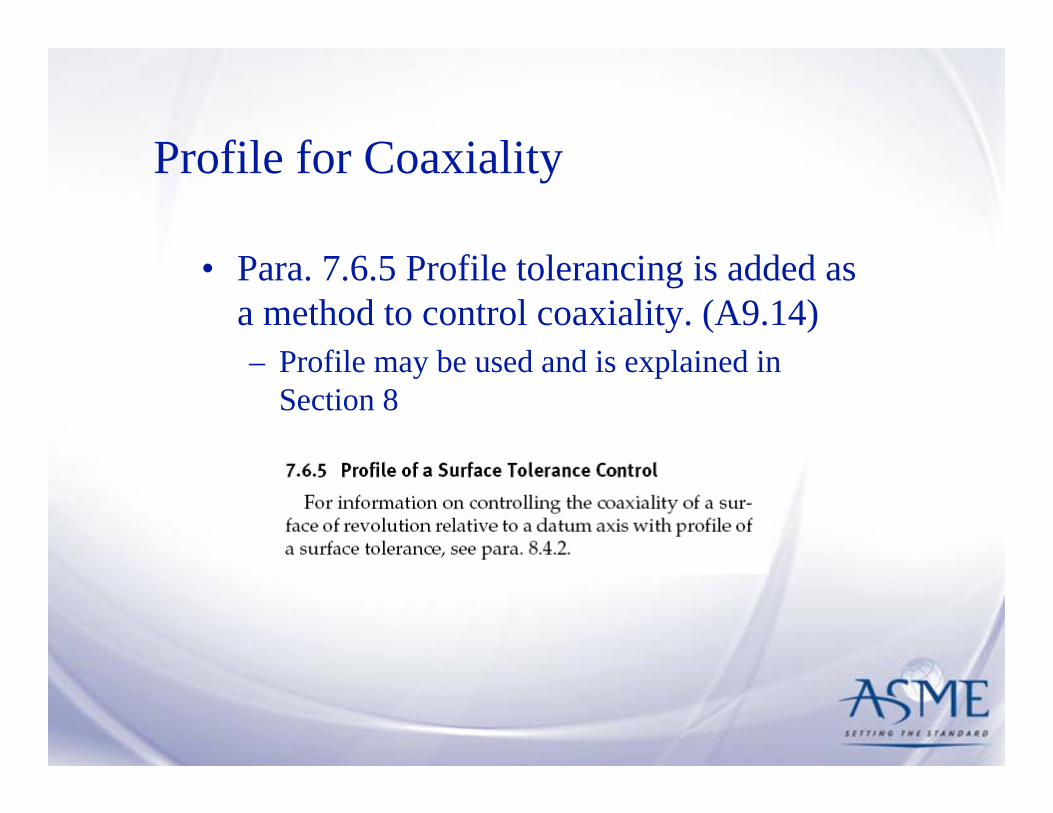
Profile for Coaxiality
• Para. 7.6.5 Profile tolerancing is added as a method to control coaxiality. (A9.14)– Profile may be used and is explained in
Section 8

Other Small Additions
• Additional tolerance may come from other features in a pattern
• Additional tolerance based on surface interpretation may be different than axis interpretation

Questions
Answers represent the opinion of the respondent and do not represent ASME or
the respondent’s employer.


Section 6Tolerances of Orientation
Dr. Don W. Shepherd
Shepherd Industries
Don Shepherd Section 6 Orientation
Location of Orientation Tolerances Section
Orientation tolerances were formerly in Section 6 with form, profile, and runout. To better guide the user of the Standard in the application of geometric dimensioning and tolerancing, orientation tolerances now are in a separate section.

Don Shepherd Section 6 Orientation
Definitions
The definitions of Angularity, Parallelism, and Perpendicularity are unchanged from ASME Y14.5M-1994. In that revision the description of the three orientation tolerances and their tolerance zones was repeated for each of the three types of tolerance. The only difference between the three descriptions was the terms angularity, parallelism, or perpendicularity. In this revision the description of the tolerances and their tolerance zones is only stated one time and applies to all three orientation tolerances.

Orientation Definition as Condensed
Don Shepherd Section 6 Orientation

Don Shepherd Section 6 Orientation
Angularity Symbol
The use of the angularity symbol meaning orientation is introduced as an alternative practice to using perpendicularity or parallelism.

Specifying Orientation for a plane surface relative to two datums
6.4
FIG. 6-4 SPECIFYING ORIENTATION FOR A PLANE SURFACE RELATIVE TO TWO DATUMS
A
BA0.12
This on the drawing
Means this
B
Datum plane B(Secondary)
Datum plane A(Primary)
0.12
0.120.12
0.12 BA
Alternative practiceas referenced in para 6.6
The surface must be between two parallelplanes 0.12 apart which are perpendicularto datum plane A. Datum feature B isinvoked to constrain an additional rotationaldegree of freedom of the datum reference
6.4.26.6
frame.
Form Tolerances at MMC
Para 6.4.5
A form tolerance applied at MMC may be explained in terms of either the surface or the derived median line/plane. In certain cases of extreme form deviation, the tolerance in terms of the feature’s derived median line/plane may not be exactly equivalent to the tolerance in terms of the surface. In such cases, the surface interpretation shall take precedence.
Don Shepherd Section 5 Form


Section 9Tolerances of Runout
Dr. Don W. ShepherdShepherd Industries

Don Shepherd Section 9 Runout
Location of Runout Tolerances SectionRunout tolerances were formerly in Section 6 with form, profile, and
orientation. To better guide the user of the Standard in the application of geometric dimensioning and tolerancing, runout tolerances now are in a separate section.