A Control Experiment Buried Fermented and Buried Non-Fermented ...

Prognosis and treatment of buried channels in river valley projects
– A geotechnical perspective
Chakraborty*, Arindom
Sharma, Vivek
Rath, Shishir
Engineering Geology Division, NHPC Ltd, Sector-33, Faridabad-121003
*E-mail of corresponding author: [email protected]
Abstract
Buried channel, also called fossil valley or paleo-channel is a geomorphic feature often found along river
valleys in mountainous terrain. It is a remnant of an inactive river or stream channel that has been filled or
buried by younger sediments. The sediments that the ancient channel is cut into or buried by are generally
unconsolidated or semi-consolidated in nature thereby having high porosity and permeability. Buried
channels can lead to severe damages in the river valley projects if not identified and treated timely. These
buried/ paleo channels are mostly filled with riverine material and subsequently convert to old terrace
deposits which act as pathways for water transmission. Keeping in view, flat topography and proximity to
river, these terraces mostly attract major human settlements. Depth of overburden along the buried river
course is often found to be more than that of the present river course. In such condition, if a dam or a
diversion structure is constructed in the downstream without properly treating the buried channel at its inlet
itself (towards reservoir), the fluctuation in water level and saturation during reservoir feeling may cause
lot of damages in the downstream. Therefore, it is extremely important to identify the inlet/outlet and the
extent of the buried channel at the investigation stage itself so that suitable geotechnical solutions like
permeation grouting, clay capping, impervious blanketing by HDPE Film, geo membrane etc. can be
suggested at DPR stage. Drilling and geophysical investigation are the two most adopted techniques for
prognosis of buried channels. However, preliminary assessment can be made by careful reconnaissance of
topographic, geologic and geomorphic set up of the area.
NHPC Limited, a premier organization in hydropower development in India has a lingering legacy of
successful negotiation of deep buried channels/fossil valleys at many projects like Parbati HE Project
Stage-II, Nimmo Bazgo HE Project etc. The paper highlights the methods and techniques used in the above
projects for prognosis of profile, depth and extent of the buried channel and also the extensive treatment
carried out (grouting, clay capping etc.) to control seepage through them. The paper also elaborates how the
experience gained from the above projects has been used effectively in finalizing methodology to control
seepage through a wide buried channel located in a Hydropower Project.
Keywords: Buried channel, river valley projects, investigations.
1. Introduction:
The steep topography and several rivers originating from the glaciers of lofty Himalayas
have been a boon in the field of producing hydroelectricity for India, Bhutan, Nepal &
adjoining countries. But these young folded mountains have also experienced several
phases of deformations. Out of the several geomorphic changes being brought by these
deformational phases in Himalayas the deviations in the course of major rivers is also
one of the deformational aspects. The sudden blockage of existing river channels due to
major land sliding can be considered as a key factor for compelling the rivers to change
its existing course. These deviations in the course of major rivers give rise to formation
of paleo/buried channels also known as fossil valleys. The fossil valleys in Himalaya

Journal of Engineering Geology Volume XLII, Nos. 1 & 2
A bi-annual Journal of ISEG June-December 2017
318
have been mostly observed in the higher altitudes once governed by the fluvioglacial
geomorphology. Formation of buried channels can also be correlated with the syn-
tectonic activities that took place during Himalayan orogeny. The burial of river valley in
large scale due to major landslides or occupancy by the moraine deposits might have
created a natural barrier or dam in the river, which may have further given rise to
impoundment of river water and lake formation resulting to reduction in transportation
and eroding capacity of the river. But in due course of time the reservoir would have
crossed the limit of impoundment and allowed the river to topple the barrier and follow a
new course. In most of the cases it has been observed that the river has shifted to right or
left into the rock and started carving a new valley. Most of these valleys are broad U-
shaped, however in few cases narrow U or V shaped gorges have also been identified
such as at the dam site of Parbati HE Project, Stage-II of NHPC. Whereas in the other
two projects of NHPC viz. Nimmo Bazgo HE Project in J&K and Goriganga IIIA HE
Project in Uttarakhand U-shaped valleys have been encountered.
Out of these three buried channels timely prognosis through detailed investigations and
appropriate treatment have been done in the buried channels of Parbati HE Project,
Stage-II and Nimmo Bazgo HE Project in J&K for constructing hydroelectric project
reservoirs. The extent and depth of the buried channel at the dam site of Goriganga IIIA
HE Project in Uttarakhand, has also been worked out through vast investigations and a
profile of the buried channel/valley has been established which indicates that the depth of
paleo channel was more than the present river course. The buried channel is mostly
filled with the riverine deposits along with the terrace deposit.
2. Challenges in Hydroelectric Projects:
The buried channels are mostly filled with unconsolidated riverine and terrace deposit. In
such condition, if a dam or a diversion structure is constructed the poundage and
subsequent fluctuation in reservoir water level may saturate the buried valley and cause
lot of damages in the downstream. The buried channel being a more permeable zone than
the surrounding bedrock may allow the reservoir water to seep in. In case of the Madkot
terrace of Goriganga IIIA HE Project the intensive recharge of groundwater may produce
a critical increase in groundwater level and may cause ground failure associated with
land subsidence. Few of the challenges posed by saturation of buried channel are as
follows:
1. Abnormal increase in ground water table
2. Washing out of fines from the outlet, if any.
3. Land Subsidence due to saturation.
4. Decrease in reservoir storage capacity.
5. Weakening of abutment, etc.
To avoid such situations it is extremely important to identify the inlet and extent of the
buried channel at the investigation stage itself so that suitable geotechnical solutions like
permeation grouting, clay capping, impervious blanketing by HDPE Film, geo
membrane etc. can be suggested at DPR stage. Drilling and geophysical investigation are

Journal of Engineering Geology Volume XLII, Nos. 1 & 2
A bi-annual Journal of ISEG June-December 2017
319
the two most adopted techniques for prognosis of buried channels. However, preliminary
assessment can be made also by careful reconnaissance of topographic, geologic and
geomorphic set up of the area.
3. Case Studies:
3.1 Fossil Valley of Parbati-II HEP (800 MW), Himachal Pradesh:
Parbati Hydroelectric Project Stage-II lies in the lesser Himalayan zone of Himachal
Pradesh and is characterized by structural hill and valley setup. The great variation in the
elevation ranging from El.1200m to 2200m above MSL is suggestive of a very young and
immature topography confirming to the late orogenic upliftment of Himalayas marked by
high mountains, narrow & glaciated valleys, buried channels, escarpments & steep
slopes. The region has also gone through several phases of deformation as exhibited in
the form of fold, faults and thrusts which is also evident from the small quartz vein
signatures observed in miniature form. The main rock types in this region belong to
Jutogh, Banjar & Larji Formations ranging in age from Pre-Cambrian to Permian and are
separated by thrusted contacts. The area is characterized by wide geological diversity and
structural complexity. The 800 MW Parbati H.E. projects is ‘inter-basin transfer’ type,
wherein the water of Parbati River is being diverted to Sainj River. The project mainly
comprises construction of 85m high Concrete Gravity Dam (Dam top El.2200m), 31.5km
long 6.0m diameter Horse Shoe/Circular shaped HRT, 3.5m diameter 2 No. inclined
pressure shaft and a Surface power house.

Journal of Engineering Geology Volume XLII, Nos. 1 & 2
A bi-annual Journal of ISEG June-December 2017
320
Picture 1 Panoramic and close view of Fossil Valley at Parbati Dam Site
The dam site is located on Parbati River near Pulga / Barshaini village, in a narrow U-
shaped gorge about 150m downstream of its confluence with Tosh nala (Pic. 1a). The
dam abuts on firm rock mass comprising schistose quartzite with thin intercalated bands
of mica schist belonging to Kullu member of Jutogh formation. The left bank had
exposures of rock with thin cover of slope wash material up to EL 2230m and beyond
that it was covered with thick fluvioglacial material. Whereas, the right bank was
extensively covered with thick fluvioglacial material up to EL 2270m. The gently sloping
topography and absence of any rock exposure on the right bank indicated towards
presence of buried channel in this area. The buried channel comprises of fluvioglacial
material comprising boulders with rock fragments in sandy silty clayey matrix.
To establish the shape and extent of fossil valley further surface & subsurface
investigations were carried out. Besides detailed geological mapping on 1:500 scale, the
dam area in general and the buried channel in particular was extensively investigated
through exploratory drilling and geophysical survey. Four Seismic profiles on the right
bank were taken above the fossil valley area with cumulative length of 800m. The fossil
Fluvioglacial material on the R/b of Dam comprising rounded boulders in medium to fine grained silty sand
Fossil Valley
Fluvioglacial material on the R/b of Dam
Dam Fossil Valley
Parbati River
Journal of Engineering Geology Volume XLII, Nos. 1 & 2
A bi-annual Journal of ISEG June-December 2017
321
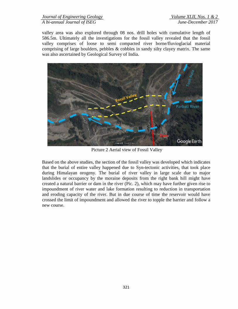
valley area was also explored through 08 nos. drill holes with cumulative length of
586.5m. Ultimately all the investigations for the fossil valley revealed that the fossil
valley comprises of loose to semi compacted river borne/fluvioglacial material
comprising of large boulders, pebbles & cobbles in sandy silty clayey matrix. The same
was also ascertained by Geological Survey of India.
Picture 2 Aerial view of Fossil Valley
Based on the above studies, the section of the fossil valley was developed which indicates
that the burial of entire valley happened due to Syn-tectonic activities, that took place
during Himalayan orogeny. The burial of river valley in large scale due to major
landslides or occupancy by the moraine deposits from the right bank hill might have
created a natural barrier or dam in the river (Pic. 2), which may have further given rise to
impoundment of river water and lake formation resulting to reduction in transportation
and eroding capacity of the river. But in due course of time the reservoir would have
crossed the limit of impoundment and allowed the river to topple the barrier and follow a
new course.
Parbati River
Dam

Journal of Engineering Geology Volume XLII, Nos. 1 & 2
A bi-annual Journal of ISEG June-December 2017
322
Figure 1 Cross section of fossil valley on right abutment of Parbati II dam
(From Parbati HE Project, Stage-II DPR, NHPC Ltd)
3.1.1 Treatment Methodology: To arrest the leakage from the fossil valley, at the time
of filling of the reservoir, a cut-off grout curtain has been placed through permeation
grouting using the Tube a Manchhettes (TAM) technique in phased manner using various
grout mix, ultrafine cement, admixtures etc. as per mix design. The grouting patter was
evolved in such a way that the entire stretch of fossil valley is treated and an impermeable
barrier/cut-off is developed in the fluvioglacial/riverine material. The cut-off has been
designed to extend from the surface up to 10m deep in the bedrock as the depth of the
fossil valley was ascertained to be around 101m.The drill holes established that the fossil
valley is mainly composed of four distinct types of materials:
i. From 0-25m Yellowish brown to grey sand with boulders of granitic gneiss,
quartzite & Mica Schist. Percentage of fine is more in comparison to coarse
material.
ii. 25-30m Fine silt without pebble/boulder
iii. 30-60m Angular to Sub angular boulders & pebbles of quartzite & schist
iv. 60-101m Silty sand with large boulders of gneiss & granitic gneiss.
During the investigation stage variable overburden permeability ranging from 1x10⁻³
to
6x10⁻⁵
was recorded in the fossil valley. Similarly, no effect of grouting on reduction in
the permeability values was observed with normal cement due to the irregular and
anisotropic pattern of grout intake. To overcome this situation a specialized agency to
carry out the permeation grouting with TAM technique was deputed. The grouting was
carried out in two stages:
a) In the first stage the grouting was carried out from surface up to the grout gallery.
This 215m linear treatment of fossil valley around the road level at El.±2200m
was designated as upper grout curtain. The depths of drill holes for upper grout

Journal of Engineering Geology Volume XLII, Nos. 1 & 2
A bi-annual Journal of ISEG June-December 2017
323
curtain were drilled in the range of few meters to ±55m upto the level of grouting
gallery at El.±2150m.
b) In the second stage, the grouting was carried out through a grouting gallery of
dimension 3.5m x 3.8m at El.2150m (Pic-3). Through this treatment gallery the
media between the gallery and the bedrock was grouted. The treatment through
this elevation was designated as lower grout curtain where the depth of drill holes
was in the range of 65-70m.
Picture 3 Grouting gallery on right abutment for treatment of fossil valley
Grouting was carried out in three rows i.e. upstream, downstream and central role
through total 536 nos. bore holes. In first phase, external treatment holes were grouted
using fine cement, whereas in the second phase the central holes were grouted using
ultrafine cement. Grouting was controlled by Pmax/Vmax (Pressure/Volume Ratio). Where
Pmax varied from 5bar to 35bar and Vmax for external holes was set at 180 litres while for
central holes it was set to 350liters. In order to seal the hollow space between the grout
hole & TAM sleeve pipes were used. This exercise has proved to be a successful attempt
to create sound & stable reservoir. Post grouting check holes and permeability tests
showed marked reduction in the permeability values before and after the grouting,
ascertaining successful treatment of the fossil valley. To verify the efficacy of grouting
and to monitor the variation in the water level before and after impounding, piezometers
have been installed downstream of the curtain.
DAM Tosh Nala
Figure 2 Grouting Pattern

Journal of Engineering Geology Volume XLII, Nos. 1 & 2
A bi-annual Journal of ISEG June-December 2017
324
3.2 Buried Channel of Nimmo-Bazgo Hydroelectric Project (45MW):
The Nimmo-Bazgo Hydroelectric Project is located in the northern side of Greater
Himalaya (Ladakh Himalaya) in Leh district of J&K on the river Indus. The project is
located in a thick pile of monotonous, syn-tectonic sedimentaries namely sandstone and
shale constituting the Indus Flysch of Ladakh region belonging to Cretaceous age. The
run of the river scheme has been constructed to harness hydroelectric potential of the
river Indus. A gross head of approx. 37m is utilized for generating 45MW of power
through three units of 15MW each. The major project components comprise of a 57m
high concrete gravity dam across river Indus, three independent intakes proposed directly
from the dam blocks to ensure silt free water entry into the penstocks & a surface
powerhouse on the right bank. The discharge from the powerhouse is directly led to the
river through tail pool. Comprehensive investigation involving surface and sub-surface
techniques viz. geological mapping, geophysical survey, core drilling, exploratory
drifting, pitting, trenching and rock mechanics test for various civil structures of the
contemplated project were applied to collect the required geological and geotechnical
data. Adequate investigations have been carried out to firm up the project components
and to serve as database for further works at different stages of the project.
Picture 4 Aerial view of buried channel on Left bank of Nimmo Bazgo Dam Site
During geological mapping a buried channel was prognosticated at the left bank, which
was further explored by geophysical survey and drill holes. The bedrock profile depicted
from 3 drill holes, namely DH-5, DH-6 & DH-10 indicated that the thickness of
overburden is about 30m.2 (up to El. 3077.32M) that is about 18m below the FRL in the
deepest section of the channel.
Buried Channel

Journal of Engineering Geology Volume XLII, Nos. 1 & 2
A bi-annual Journal of ISEG June-December 2017
325
Figure 3 Cross Section of Buried Channel on Left Abutment of Nimmo Bazgo Dam
A one meter thick impervious clay blanket along with a positive 15meter thick cut off
wall was provided to minimize the seepage through the buried channel inlet and left
abutment. Subsequently, grouting was carried out through 51no. drill holes up to the
depth of the bed rock. The grout holes were drilled at an interval of 6m c/c to achieve the
permeability of lugeon ≤5.
3.3 Prognosis of Buried Channel in Goriganga IIIA HE Project, Uttarakhand,
India:
Goriganga Stage-IIIA Project (150 MW) is envisaged on river Goriganga, a right bank
tributary of River Kali (also called Mahakali and Sharda) in Pithoragarh district of
Uttarakhand and involves construction of a 63.8 m long and 30.1 m high barrage at
Madkot. The river has carved a 24m wide narrow gorge through rocky escarpments of
schistose/siliceous limestone. On the left bank, there is a rocky knob which is almost
identical to the right abutment having similar discontinuity characteristics. This rocky
knob is overlain by a riverine terrace above EL ±1232M. Exploratory drilling affirmed
that the rock mass at left abutment recedes beneath the riverine terrace resulting in
reduction of abutment thickness. The uppermost part of barrage (EL 1232M to EL
1240M) shall abut against riverine deposits comprising of semi consolidated sandy
gravels and boulders. Width of the riverine terrace deposit at the barrage section is
±340m. The terrace abuts against a steep escarpment comprising of moderately strong,
highly jointed, slightly weathered siliceous limestone and phyllite. Although the
proposed barrage abuts on the rock, the flat terrace on the left bank of barrage axis has
always remained the matter of curiosity. Approximately, 120m D/s of Madkot Bridge
the canyon once again opens up as a broad U-shaped valley. Boreholes drilled at the river
channel deciphers that the bedrock is available at 30-32m depth below river bed at EL
±1180.00 M. To delineate configuration of Madkot terrace in the left bank, seven number
holes (cumulative depth 417m) were drilled during FR stage and further substantiated by

Journal of Engineering Geology Volume XLII, Nos. 1 & 2
A bi-annual Journal of ISEG June-December 2017
326
eight number drill holes (cumulative depth 491m) and eight number seismic refraction
profiles (cumulative length 1575m) during DPR stage (Fig.-4). The results of drill holes
as well as seismic refraction profiles reveal that the depth of overburden at Madkot
terrace varies from 15m to as deep as ±90m. Such variation in overburden signifies
presence of a Palaeo channel below the terrace deposit (Fig.-5).
Figure 4 Exploration Plan of Goriganga Dam Site
Figure 5 Cross Section of Paleo Channel on Left Abutment of Goriganga IIIA Dam
As the anticipated bedrock elevation in the Madkot terrace area (EL±1145M) is deeper
than that encountered in the existing river channel (EL± 1180M), there might be
possibilities of loss of water below the terrace during reservoir impoundment. To assess
the disposition of bedrock within the Madkot terrace, a geological section along the flow
direction from upstream to downstream passing through the centre of the terrace has
been prepared (Fig.-6).
ND
H-1
5 (8
6.5m
)Proposed Cut-Off
NDH D
N
D
Journal of Engineering Geology Volume XLII, Nos. 1 & 2
A bi-annual Journal of ISEG June-December 2017
327
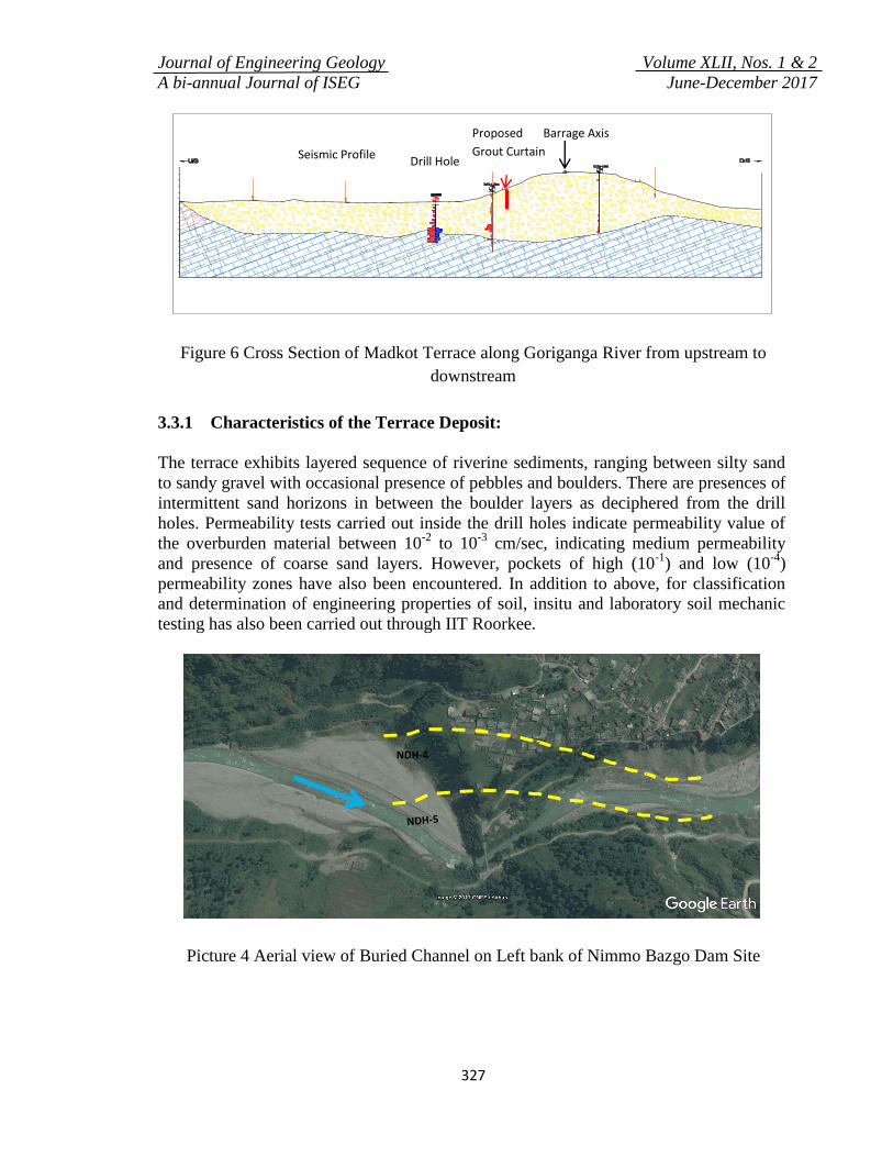
Figure 6 Cross Section of Madkot Terrace along Goriganga River from upstream to
downstream
3.3.1 Characteristics of the Terrace Deposit:
The terrace exhibits layered sequence of riverine sediments, ranging between silty sand
to sandy gravel with occasional presence of pebbles and boulders. There are presences of
intermittent sand horizons in between the boulder layers as deciphered from the drill
holes. Permeability tests carried out inside the drill holes indicate permeability value of
the overburden material between 10-2
to 10-3
cm/sec, indicating medium permeability
and presence of coarse sand layers. However, pockets of high (10-1
) and low (10-4
)
permeability zones have also been encountered. In addition to above, for classification
and determination of engineering properties of soil, insitu and laboratory soil mechanic
testing has also been carried out through IIT Roorkee.
Picture 4 Aerial view of Buried Channel on Left bank of Nimmo Bazgo Dam Site
DDH-
ND
NDH-4
Seismic Profile Drill Hole
Proposed
Grout Curtain
Barrage Axis
Journal of Engineering Geology Volume XLII, Nos. 1 & 2
A bi-annual Journal of ISEG June-December 2017
328
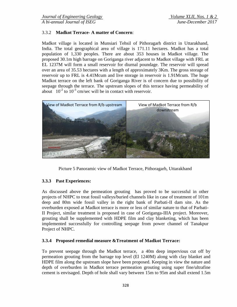
3.3.2 Madkot Terrace- A matter of Concern:
Madkot village is located in Munsiari Tehsil of Pithoragarh district in Uttarakhand,
India. The total geographical area of village is 171.11 hectares. Madkot has a total
population of 1,330 peoples. There are about 353 houses in Madkot village. The
proposed 30.1m high barrage on Goriganga river adjacent to Madkot village with FRL at
EL 1237M will form a small reservoir for diurnal poundage. The reservoir will spread
over an area of 35.53 hectares with a length of approximately 3Km. The gross storage of
reservoir up to FRL is 4.41Mcum and live storage in reservoir is 1.91Mcum. The huge
Madkot terrace on the left bank of Goriganga River is of concern due to possibility of
seepage through the terrace. The upstream slopes of this terrace having permeability of
about 10-2
to 10-3
cm/sec will be in contact with reservoir.
Picture 5 Panoramic view of Madkot Terrace, Pithoragarh, Uttarakhand
3.3.3 Past Experiences:
As discussed above the permeation grouting has proved to be successful in other
projects of NHPC to treat fossil valleys/buried channels like in case of treatment of 101m
deep and 80m wide fossil valley in the right bank of Parbati-II dam site. As the
overburden exposed at Madkot terrace is more or less of similar nature to that of Parbati-
II Project, similar treatment is proposed in case of Goriganga-IIIA project. Moreover,
grouting shall be supplemented with HDPE film and clay blanketing, which has been
implemented successfully for controlling seepage from power channel of Tanakpur
Project of NHPC.
3.3.4 Proposed remedial measure &Treatment of Madkot Terrace:
To prevent seepage through the Madkot terrace, a 40m deep impervious cut off by
permeation grouting from the barrage top level (El 1240M) along with clay blanket and
HDPE film along the upstream slope have been proposed. Keeping in view the nature and
depth of overburden in Madkot terrace permeation grouting using super fine/ultrafine
cement is envisaged. Depth of hole shall vary between 15m to 95m and shall extend 1.5m
NDH-1 View of Madkot Terrace from R/b downstream
View of Madkot Terrace from R/b upstream
Journal of Engineering Geology Volume XLII, Nos. 1 & 2
A bi-annual Journal of ISEG June-December 2017
329
below bedrock level. Grouting operation shall be carried out for a length of 50cm at a time
in 3 rows. The diameter of each hole shall be 100mm. Spacing between two primary holes
shall be 3m and that between one primary and secondary hole shall be 1.5m longitudinally
and 750mm transversely in a c/c staggered pattern. Permeation grouting is a specialized
job and shall be carried out through an expert agency during construction stage. Before
actual execution, some trial grouting shall be carried out through them in the terrace area.
Groutability test has not been carried out as grouting trial using normal cement grouting
method shall not yield any fruitful result.One of the opinion for prevention of insitu
geotechnical characteristics of the terrace is to carry out permeation grouting from the
existing road levelat EL ±1245M up to a depth of ±40m in a single stage. As per the
studies carried out by NHPC, the flow velocity below 40m depth (±EL 1200M) shall
reduce significantly and may not cause any appreciable leakage after impoundment and
resulting subsidence of Madkot terrace. The detailed modus operandi of permeation
grouting (including the depth and spacing of holes) shall be finalized during detailed
design/tender stage.
4. Conclusion:
With ever increasing emphasis on cost cutting in highly competitive construction
markets, reduction in expenditure onsite investigation has become a reality. Although, it
is true that elimination of all risks in construction project is unlikely, even with the most
elaborate site investigation program, however, to avoid any kind of unforeseen problems
during or after the construction of a project, it is important to diagnose the problem at
early stage and treat the same effectively. Occurrence of buried channels is one such kind
of topographical feature which can lead to serious issues during and after construction of
the hydroelectric projects. Timely prognosis of these buried channels through detailed
investigations and subsequently, appropriate treatment is an important aspect of
consideration especially in the hydroelectric projects. The authors have tried to present
that with adequate surface and subsurface investigation techniques timely Prognosis and
Treatment of Buried Channels in River Valley Projects is possible.
References:
1. Bhatnagar, Sharad and Singh, A.K., Treatment of fossil valley in Dam Area : A
case study, CBIP Memoir, 2012
2. Detailed Project Report (Advance Copy), Goriganga III A HE Project, NHPC
Limited, July 2017.
3. Detailed Project Report, Parbati-II HE Project, NHPC Limited.
4. Detailed Project Report, Nimoo Bazgo HE Project, January 2004.
5. Patni B D, Sharma J K, Chakraborty Arindom (2009), Nimmo Bazgo HE Project -
A Step Towards the Construction of India’s Highest Altitude Hydroelectric
Project, proceedings of 2nd
Indian Rock Conference INDOROCK-2009 by
ISRMTT.