ProFire-M Series Operation and Maintenance Manual
80
Manual Part No. 750-207 04/2009 Profire M Burner Gas, #2-5 Oil, #2-6 Oil, or Combination Installation Operation Maintenance Parts
Transcript of ProFire-M Series Operation and Maintenance Manual

Manual Part No. 750-207 04/2009
Profire MBurner
Gas, #2-5 Oil, #2-6 Oil,or Combination
InstallationOperation
MaintenanceParts
Table Of Contents


ONLY F ACTORY AUTHORIZED BURNER SERVICE PERSONNEL SHOULD ST ART- UP, ADJUST, OR SER VICE THIS EQUIPMENT.
WARNING
M/SERIESInstallation, Operation,Service,and Parts Manual
750-207 04/09

Monroe, Wisconsinwww.cleaverbrooks.com

M/SERIES TABLE OF CONTENTSSECTION 1:0
OPERATING PRECAUTIONS ................................................1MODEL DESIGNATIONS, SIZES & INPUTS .........................2
CHAPTER 1. INTRODUCTION A. GENERAL INFORMATION ................................................3B. DESCRIPTION ...................................................................3C. OPERATING CONTROLS ............................................. 3-4D. FLAME SAFEGUARD CONTROLS ...................................4E. GAS SYSTEM ....................................................................5F. PILOT GAS TRAIN ............................................................6G. OIL SYSTEM .................................................................. 6-8
CHAPTER 2. INSTALLATIONA. DRAFT CONDITIONS........................................................9B. AIR SUPPLY ......................................................................9C. COMBUSTION CHAMBER DESIGN ........................... 9-10D. DRY OVEN AND BURNER INSTALLATION ...............11-13E. COMPRESSOR MODULE ...............................................13F. GAS PIPING ....................................................................13G. FUEL OIL PIPING ...................................................... 13-14H. INSTALLATION CHECKLIST ...........................................14
GAS PIPING SCHEMATICS ................................................15 OIL PIPING SCHEMATICS ............................................ 16-18
CHAPTER 3. OPERATIONA. PREPARATION FOR INITIAL START-UP ........................19B. FIRING PREPARATIONS FOR GAS BURNERS ............19C. FIRING PREPARATIONS FOR OIL BURNERS ........ 19-20D. SEQUENCE OF OPERATION .........................................20E. START-UP AND OPERATING .................................. 20-21F. NORMAL OPERATION ....................................................21G. SHUTDOWN ....................................................................21H. EXTENDED SHUTDOWN ...............................................21I. NORMAL OPERATION. ....................................................30J. SHUTDOWN. ....................................................................30
CHAPTER 4. ADJUSTMENTSA. GENERAL ....................................................................... 22B. COMBUSTION ADJUSTMENT ON GAS AND OIL .......... 22C. ELECTRICAL INTERFERENCE TEST ............................ 22D. GAS SYSTEM .............................................................22-23E. OIL SYSTEM ...............................................................23-24F. COMBUSTION AIR SYSTEM............ .............. ................24G. MODULATING MOTOR................................. .................. 25H. LINKAGE ADJUSTMENTS .........................................25-26
CHAPTER 5. MAINTENANCEA. GENERAL. ....................................................................... 27B. CONTROL SYSTEM. ....................................................... 27C. COMBUSTION AIR IMPELLER ...................................... 27D. GAS SYSTEM .................................................................. 28E. OIL SYSTEM ...............................................................28-29F. BURNER HEAD ...........................................................29-31G. BURNER MOUNTING INSPECTION .............................. 31H. OIL STRAINERS .............................................................. 31I. DRAWER ASSEMBLY ..................................................31-33J. MAINTENANCE FLOW CHART. ...................................... 34
CHAPTER 6. TROUBLE SHOOTINGA. AWARENESS. .................................................................. 35B. EMERGENCY SHUTDOWN. ........................................... 35TROUBLE SHOOTING GUIDE. ......................................36-38
WARRANTY POLICY. .....................................................39-40START-UP / SERVICE REPORT. ......................................... 41PRODUCT SATISFACTION SURVEY. ................................. 42
PARTS SECTION 2:0 AIR CLEANER.......................................................... 13, 17, 19AIR MODULATION ............................................................... 23BLAST TUBES ....................................................................... 5 CAM TRIM ............................................................................ 25 COILS, COOLING ...................................................... 5, 17, 19COMPRESSORS, AIR ...................................................17, 19CONTROLS, ELECTRICAL ................................................. 27DIFFUSERS .......................................................................7, 9DAMPER, LOUVER-TYPE ..................................................... 5DRAWER ASSEMBLIES .................................................... 7, 9DRY OVENS .......................................................................... 5ELECTRODES, IGNITION ................................................. 7, 9FILTERS, AIR (REPLACEMENT) ............................. 13, 17, 19FILTERS, OIL ................................................................. 17, 19GAUGES, PRESSURE ............................................ 13, 17, 19HEATERS, OIL ............................................................... 13, 15HOUSING, FAN ...................................................................... 5IMPELLERS, AIR....................................................................5MODULES, SEPARATE COMPRESSOR ...................... 17, 19MOTORS, ELECTRIC - BLOWER ......................................... 5 - COMPRESSOR ....................................................... 17, 19 - MODULATING ......................................................... 23, 25 - OIL PUMP .......................................................... 11, 13, 15NOZZLES, OIL ................................................................... 7, 9PILOTS, GAS ..................................................................... 7, 9PUMPS, OIL METERING ..................................................... 13REGULATOR, GAS .............................................................. 21SCANNER ..........................................................................7, 9SHEAVES .............................................................................19STARTERS, MOTOR ........................................................... 27STRAINERS, OIL ........................................................... 17, 19SWITCHES, AIR ............................................................... 5, 27SWITCHES, CONTROL ....................................................... 27SWITCHES, GAS ................................................................. 21TRANSFORMERS .................................................................5 TANKS, AIR-OIL ....................................................... 13, 17, 19 VALVES, AIR .................................................................. 17, 19VALVES, GAS ...................................................................... 21VALVES, OIL ............................................................ 11, 13, 15V-BELTS ...............................................................................19
Sec1:1
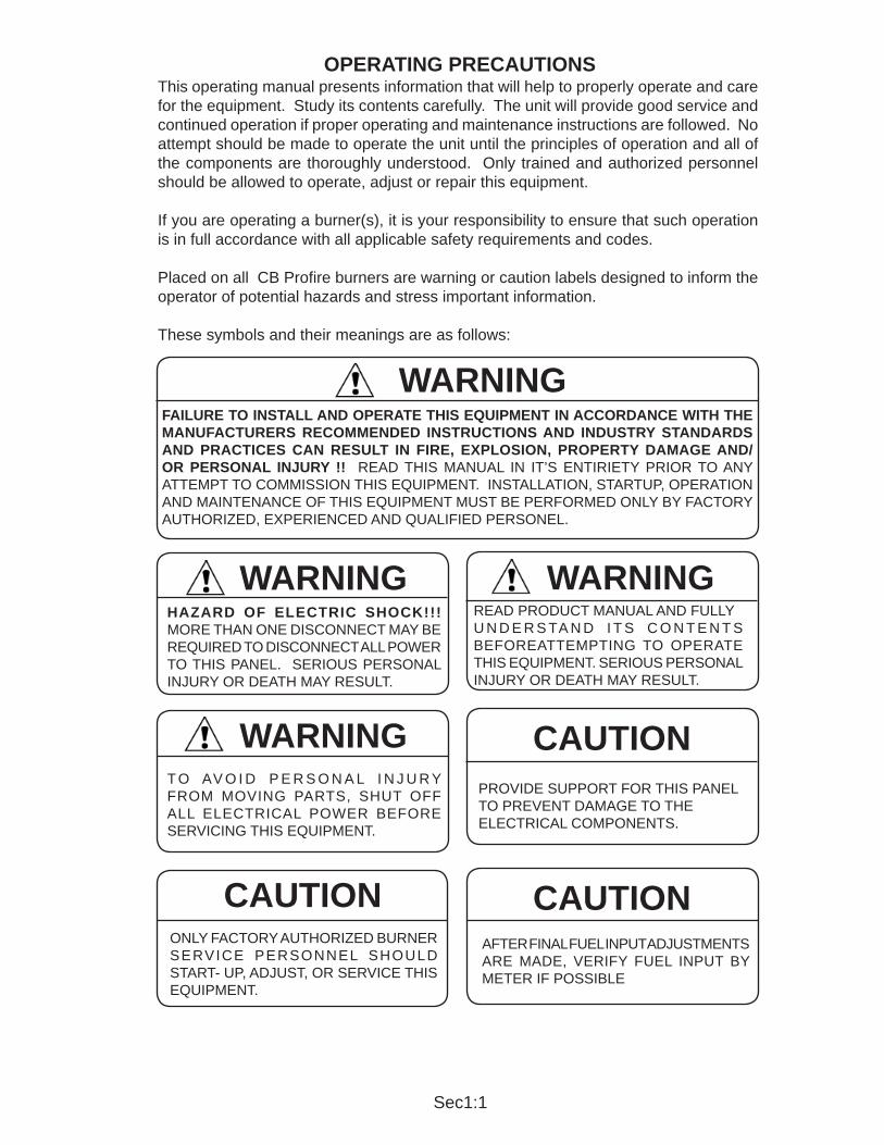
This operating manual presents information that will help to properly operate and care for the equipment. Study its contents carefully. The unit will provide good service and continued operation if proper operating and maintenance instructions are followed. No attempt should be made to operate the unit until the principles of operation and all of the components are thoroughly understood. Only trained and authorized personnel should be allowed to operate, adjust or repair this equipment.
If you are operating a burner(s), it is your responsibility to ensure that such operation is in full accordance with all applicable safety requirements and codes.
Placed on all CB Prof re burners are warning or caution labels designed to inform the operator of potential hazards and stress important information.
These symbols and their meanings are as follows:
OPERATING PRECAUTIONS
WARNINGFAILURE TO INSTALL AND OPERATE THIS EQUIPMENT IN ACCORDANCE WITH THE MANUFACTURERS RECOMMENDED INSTRUCTIONS AND INDUSTRY STANDARDS AND PRACTICES CAN RESULT IN FIRE, EXPLOSION, PROPERTY DAMAGE AND/OR PERSONAL INJURY !! READ THIS MANUAL IN IT’S ENTIRIETY PRIOR TO ANY ATTEMPT TO COMMISSION THIS EQUIPMENT. INSTALLATION, STARTUP, OPERATION AND MAINTENANCE OF THIS EQUIPMENT MUST BE PERFORMED ONLY BY FACTORY AUTHORIZED, EXPERIENCED AND QUALIFIED PERSONEL.
READ PRODUCT MANUAL AND FULLY U N D E R S TA N D I T S C O N T E N T S BEFOREATTEMPTING T O OPERATE THIS EQUIPMENT. SERIOUS PERSONAL INJURY OR DEATH MAY RESULT.
PROVIDE SUPPORT FOR THIS PANEL TO PREVENT DAMAGE TO THE ELECTRICAL COMPONENTS.
CAUTION
ONLY FACTORY AUTHORIZED BURNER SERVICE PERSONNEL SHOULD START- UP, ADJUST, OR SERVICE THIS EQUIPMENT.
CAUTION
WARNINGHAZARD OF ELECTRIC SHOCK!!! MORE THAN ONE DISCONNECT MAY BE REQUIRED TO DISCONNECT ALL POWER TO THIS PANEL. SERIOUS PERSONAL INJURY OR DEATH MAY RESULT.
WARNING
T O AV O I D P E R S O N A L I N J U R Y FROM MOVING P ARTS, SHUT OFF ALL ELECTRICAL POWER BEFORE SERVICING THIS EQUIPMENT.
WARNING
AFTER FINAL FUEL INPUT ADJUSTMENTS ARE MADE, VERIFY FUEL INPUT BY METER IF POSSIBLE
CAUTION

Sec1:2
THE INSTALLATION OF A BURNER SHALL BE IN ACCORDANCE WITH THE REGULATIONS OF AUTHORITIES HAVING JURISDICTION. THE EQUIPMENT MUST BE INSTALLED IN ACCORDANCE WITH APPLICABLE LOCAL, STATE OR PROVINCIAL INSTALLATION REQUIREMENTS INCLUDING THE NATIONAL ELECTRICAL CODE (NEC) AND ASSOCIATED INSURANCE UNDERWRITERS. WHERE APPLICABLE, THE CANADIAN GAS ASSOCIATION (CGA) B149 AND CANADIAN STANDARD ASSOCIATION (CSA) B140 AND B139 (FOR OIL BURNERS) CODES SHALL PREVAIL.
OIL AND GAS BURNING EQUIPMENT SHALL BE CONNECTED TO FLUES HAVING SUFFICIENT DRAFT AT ALL TIMES, TO ASSURE SAFE AND PROPER OPERATION OF THE BURNER.
THE M/SERIES BURNERS ARE DESIGNED TO BURN EITHER GAS OR LIGHT OIL No.1 OR 2 AS DEFINED BY ASTM D396-1978 SPECIFICATIONS, AND HEAVY OILS.DO NOT USE GASOLINE, CRANKCASE OIL, OR ANY OIL CONTAINING GASOLINE.
Model designations are based on the type of fuel(s) to be f red and the amount of furnace pressure to be over-come. Burner size is based on f ring rate (rated input in BTU/HR).
Further warning and caution references have been made in this manual and should be adhered to for smooth operation of the burner.
WARNING
CAUTION
NOTE
This symbol precedes information which, if disregarded, may result in injury to the user of the burner or to others.This symbol precedes information which, if disregarded, may result in damage to the burner.This symbol precedes information which is vital to the operation or maintenance of the burner.
MODELSSTANDARD FUEL - AIR ATOMIZATION
MG GASMM #2-5 OIL
MMG #2-5 OIL and GASME #2-6 OIL
MEG #2-6 OIL and GAS
EXAMPLE: Model number on nameplate isMM-42, indicating it is a combination No. 2 to 5 oil burner with input rated at 4,200 MBTU per hour, against furnace pressures up to 2.0” W.C.
BURNER SIZE AND RATED FURNACE PRESSURE - M/BURNER:M14 to 30 1.5” W.C.M34 to 105 2.0” W.C.
RATED BURNER INPUTSIZE MBTU/HR US GPH
14 1,400 10
16 1,680 12
19 1,960 1422 2,200 1425 2,490 1828 2,800 2030 3,150 22.534 3,500 2542 4,200 31.154 5,600 4063 6,300 4584 8,400 60105 10,500 75
* Gas input based on natural Gas at 1,000 Btu/cu.ft. and 0.60 specif c gravity. ** Oil input based on 140,000 Btu/gal.*** Refer to burner nameplate data for correct manifold pressures.
Sec1:3
CHAPTER 1INTRODUCTION
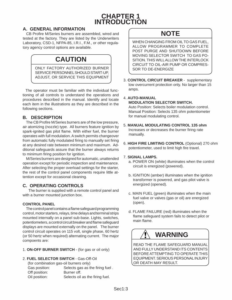
3. CONTROL CIRCUIT BREAKER - supplementary low overcurrent protection only. No larger than 15 amps.
4. AUTO-MANUAL MODULATION SELECTOR SWITCH. Auto Position: Selects boiler modulation control. Manual Position: Selects 135 ohm potentiometer for manual modulating control.
5. MANUAL MODULATING CONTROL 135 ohm Increases or decreases the burner f ring rate manually.
6. HIGH FIRE LIMITING CONTROL (Optional) 270 ohm potentiometer, used to limit high f re travel.
7. SIGNAL LAMPS. a. POWER ON (white) illuminates when the control circuit is energized (powered). b. IGNITION (amber) illuminates when the ignition transformer is powered, and gas pilot valve is energized (opened). c. MAIN FUEL (green) illuminates when the main fuel valve or valves (gas or oil) are energized (open).
d. FLAME FAILURE (red) illuminates when the f ame safeguard system fails to detect pilot or main f ame.
A. GENERAL INFORMATION CB Prof re M/Series burners are assembled, wired and tested at the factory . They are listed by the Underwriters Laboratory, CSD-1, NFPA-85, I.R.I., F.M., or other regula-tory agency control options are available.
The operator must be familiar with the individual func-tioning of all controls to understand the operations and procedures described in the manual. Identify and locate each item in the illustrations as they are described in the following sections.
B. DESCRIPTION The CB Prof re M/Series burners are of the low pressure, air atomizing (nozzle) type. All burners feature ignition by spark-ignited gas pilot f ame. With either fuel, the burner operates with full modulation. A switch permits changeover from automatic fully modulated f ring to manually set f ring at any desired rate between minimum and maximum. Ad-ditional safeguards assure that the burner always returns to minimum f ring position for ignition. M/Series burners are designed for automatic, unattended operation except for periodic inspection and maintenance. After selecting the proper overload settings for the starter, the rest of the control panel components require little at-tention except for occasional cleaning. C. OPERATING CONTROLS The burner is supplied with a remote control panel and with a burner mounted junction box.
CONTROL PANEL The control panel contains a f ame safeguard programming control, motor starters, relays, time delays and terminal strips mounted internally on a panel sub-base. Lights, switches, potentiometers, a control circuit breaker and f ame safeguard displays are mounted externally on the panel. The burner control circuit operates on 115 volt, single phase, 60 hertz (or 50 hertz when required) alternating current. The major compoents are:
1. ON-OFF BURNER SWITCH - (for gas or oil only)
2. FUEL SELECTOR SWITCH - Gas-Off-Oil (for combination gas-oil burners only) Gas position: Selects gas as the f ring fuel . Off position: Burner off. Oil position: Selects oil as the f ring fuel.
CAUTIONONLY FACTORY AUTHORIZED BURNER SERVICE PERSONNEL SHOULD START-UP, ADJUST, OR SERVICE THIS EQUIPMENT
WHEN CHANGING FROM OIL TO GAS FUEL, ALLOW PROGRAMMER TO COMPLETE POST PURGE AND SHUTDOWN BEFORE MOVING SELECTOR SWITCH TO GAS PO-SITION. THIS WILL ALLOW THE INTERLOCK CIRCUIT TO OIL-AIR PUMP OR COMPRES-SOR TO DE-ENERGIZE
NOTE
READ THE FLAME SAFEGUARD MANUAL AND FULLY UNDERSTAND ITS CONTENTS BEFORE ATTEMPTING TO OPERATE THIS EQUIPMENT. SERIOUS PERSONAL INJURY OR DEATH MAY RESULT.
WARNING

Sec1:4
AIR VOLUME REGULATOR The volume control blades are positioned by linkage from the modulating motor.
AIR HANDLING SECTION the hinged assembly houses the impeller, motor, damper assembly, and air straighteners.
COMBUSTION AIR PROVING SWITCH A pressure sensitive switch actuated by air pressure cre-ated by the impeller. Contacts close to prove combustino air f ow.
DIFFUSER An air f ow diffuser stabilizes f ame front.
FLAME SAFEGUARD CONTROLS Automatically programs each starting, operating and shutdown cycle in conjunction with operating, limit, and interlock devices. This includes, in timed sequence, opera-tion of the blower motor, ignition system, fuel valve(s) and modulating motor. The sequence includes air purge prior to ignition and after burner shutdown. The f ame scanner monitors both oil and gas f ames and instantly responds to loss of f ame. The control recycles automatically during normal opera-tion, or following a power interruption. It must be manually reset following a safety shutdown. An internal checking circuit, effective on every start, will prevent burner opera-tion in the event the f ame relay is held in.
FLAME SCANNER Monitors gas or oil pilot f ames and energizes the pro-grammer's f ame relay in response to a f ame. It monitors main f ame (oil or gas) after termination of pilot proving period.
MOTORS Drive impeller, air/oil metering unit, oil metering unit, fuel unit, and air compressor.
MOTOR STARTERS Energize motors.
IGNITION TRANSFORMER Provides high voltage spark for ignition of gas pilot or main f ame on direct spark models.
MODULATING MOTOR Operates the air damper and fuel rate valves through a linkage system to adjust air-fuel ratios under all load condi-tions. The low f re switch, an integral auxiliary switch, must be closed to prove that the air damper and fuel metering valve or metering unit, are in the low f re position before ignition can occur.
D. COMBUSTION AIR SYSTEM The air handling section is hinged for easy access to the air and f ring head components. Centrifugal axial air f ow is a true forced draft design.
Figure 1-1Centrifugal Axial Air Flow
TO AVOID PERSONAL INJURY FROM MOVING PARTS, SHUT OFF ALL ELECTRICAL POWER BEFORE SERVICING THIS EQUIPMENT.
WARNING
IMPELLER Combustion air is supplied by a heavy duty balanced backward curved impeller. The impeller remains free from diret accumulation.
MOTOR The impeller is directly driven by the motor at 3450 rpm.
OPTIONAL MOT OR/ IMPELLER COMBI-NATIONS ARE AVAILABLE FOR HIGHER FURNACE PRESSURES, HIGH ALTITUDE LOCATIONS, AND 50 CYCLE POWER
NOTE
Figure 1-2Diffuser and Drawer Assembly
Electrode
Gas Pilot Assembly
Nozzle Body and TipDiffuser
Flame Detector Heat Block Scanner Sight Tube

Sec1:5
LOW GAS PRESSURE SWITCH (Models 29-105) A pressure actuated switch that remains closed when gas pressure is above a preselected setting. Should the pressure drop below this setting, the switch contacts will open, causing the main gas valve(s) to close. This switch requires manual reset after being tripped.
F. PILOT GAS TRAIN A solenoid valve that opens during the ignition period to admit fuel to the pilot. It closes after main f ame is estab-lished.
GAS PRESSURE REGULATOR Reduces gas pressure to that required by the pilot.
GAS PILOT SHUT-OFF COCK For manually closing the pilot gas supply.
OPERATION Metered gas f ows through the main gas shutof f cock, through the pressure regulator to the automatic gas valve(s) and butterf y valve to the gas manifold. The butterf y gas valve modulates f ow to burner input demand. The butterf y valve is positioned through mechani-cal linkage by the modulating motor. The air control damper is positioned simultaneously by the modulating motor. The automatic gas valve(s) cannot be energized unless the combustion air proving switch is closed. The low and high gas pressure switches must be closed to prove proper gas pressure.
Figure 1-3
OPERATION Air from the impeller f ows through the blast tube and dif-fuser to mix with fuel in the ignition zone. Combustion air f ow rate is determined by the position of the air regulating blades at the inlet of the impeller. Linking the air f ow with fuel f ow provides eff cient combustion at all f ring rates.
E. GAS SYSTEMMAIN GAS TRAIN COMPONENTS Depending upon the requirements of the regulating au-thority, the gas control system and gas train may consist of some, or all, of the following items. A typical gas train is shown in Figure 1-3.
GAS VOLUME VALVE The butterf y type valve is positioned by linkage from the modulating motor and controls the rate of f ow of gas.
MAIN GAS VALVES Electrically operated safety shutoff valve(s) that open to admit gas to the burner. Standard U.L. burners include:
- Models: 14-22; Diaphragm gas valve - Models: 28-42; One motorized gas valve w/closure interlock - Models: 54-105; One motorized gas valve w/closure interlock and one solenoid valve
MAIN GAS REGULATOR Regulates gas train pressure to speci f ed pressure re-quired at inlet to gas train. Input is set by main gas pressure regulator adjustment.
MAIN GAS COCKS For manual shutof f of the gas supply upstream of the pressure regulator. A second shutof f cock downstream of teh main gas valve(s) provides a means of testing for leakage through the gas valve(s).
HIGH GAS PRESSURE SWITCH (Models 28-105) A pressure actuated switch that remains closed when gas pressure is below a preselected setting. Should the pres-sure rise above the setting, the switch contacts will open causing main gas valve(s) to close. This switch requires manual reset after being tripped.
GAS TRAIN COMPONENTS UPSTREAM OF THE BUTTERFLY VALVE ARE SHIPPED LOOSE TO BE MOUNTED BY THE INSTALLER.
NOTE
Typical Gas Train
PILOT GAS SUPPLY CONNECTION MUST BE UPSTREAM OF THE MAIN GAS PRESSURE REGULATOR
NOTE

Sec1:6
A normally open vent valve, if required, is located between the two automatic gas valve(s). This valve is shut when the automatic gas valve(s) are open. When the automatic valve(s) are closed, the vent valve is open for venting gas to the outside, should any be present.
G. OIL SYSTEMAIR ATOMIZING BURNERS Models MM, MMG, ME and MEG burners use compressed air for atomization. Atomizing air is independent of combus-tion air. Either of two air/oil systems are used, depending on burner size and fuel. (1) Models MM, MMG 14-105 use an integral air compressor/oil metering unit mounted on the burner and driven by a separate motor. (2) All models ME and MEG are supplied with a separate compressor module for mounting near the burner . The separately driven oil metering unit is mounted on the burner.
3-WAY SOLENOID VALVE Metered oil enters the common port of the 3-way solenoid valve. During shutdown, pre and post purge, the valve is de-energized (N.C. port closed) and all metered fuel oil returns to the storage tank. When the valve is energized, metered oil is directed to the nozzle through the N.C. port.
NOZZLE ASSEMBLY The nozzle assembly consists of four main parts: body, compression spring, swirler , and tip. The swirler is held against the nozzle tip by the compression spring. The nozzle body has inlet ports for air and oil lines. Metered fuel oil enters the nozzle body and f ows through a tube to the swirler. Oil is forced from the core of the swirler to the side ports where it meets with the atomizing air. Atomizing air enters and passes through the nozzle body to grooves in the swirler, where it mixes with fuel oil. Air/oil passes through the grooves and out of the nozzle orif ce in a cone of atomized oil. Proper velocity and angle of the f ne spray ensures good mixing with the combustion air , providing quiet starts and excellent combustion ef f ciency. During pre and post purge, the nozzle tip is purged with air. This prevents afterdrip or baked-on residue.
NOZZLE LINE ELECTRIC HEATER Provides heat for No. 4, 5 and 6 fuel oil and is located between the metering pump and 3-way valve. This heater should not be used as a continuous run line heater . The heater has an adjustable thermostat and a cold oil lockout switch which prevents burner from starting until proper atomizing temperature is attained.
OIL STRAINER Prevents foreign matter from entering the burner oil system.
ATOMIZING AIR PROVING SWITCH Pressure actuated switch contacts close when suff cient atomizing air pressure is present. The oil valve will not open unless switch contacts are closed.
AIR/LUBE OIL TANK Burner mounted tank stores compressed air for oil atomi-zation and oil for compressor lubrication. Contains wire mesh f lter to separate lube oil from compressed air.
INTEGRAL AIR/OIL UNIT Model designation MM, MMG No. 2 through 5 oil with air atomization. These models utilize an integral air compres-sor/ oil metering unit which is separately driven at 1725 rpm and mounted on the burner. See Figure 1-5.
AIR COMPRESSOR Air is drawn into the vane-type, rotary compressor section of the air/oil unit through an air cleaner. The compressed air f ows to an air-lube oil tank which serves the multiple purpose of lube oil mist recovery , lube oil sump and air storage. The compressor is cooled and lubricated continuously by oil under pressure from the bottom of the tank. Oil vapor is extracted from the compressor air, by a mist eliminator in the upper section of the tank. Atomizing air f ows to the nozzle at a constant volume, but air pressure increases as the f ring rate increases. Atomizing air is regulated by an adjusting valve in the return air line on integral metering units or in the air inlet on air compressor module burners.
Figure 1-5Figure 1-4Nozzle Assembly Integral Air/Oil Unit

Sec1:7
OIL METERING Fuel oil under nominal pressure in the circulating loop, f ows to the adjustable positive displacement, (volumetric metering unit). Oil metering is accomplished by changing the piston stroke by means of an eccentric shaft and pin assembly. The pistons reciprocate in a rotor assembly , turning in a hardened steel sleeve having oil inlet and discharge slots. During each revolution the pistons go through the following cycle:
1. Inlet Cycle: The piston is at the bottom dead center position. At this position, the cavity between the top of the piston and the outside diameter of the rotor f lls with oil.
2. Discharge Cycle: (180° from inlet cycle.) The piston is at the top dead center position. At this position, the oil is forced out of the discharge port to the nozzle. The piston stroke length is determined by the position of the eccentric shaft and plate.
The piston adjustment plate is positioned by an adjustable eccentric shaft. The eccentric shaft is positioned by the modulator through adjustable linkage. Counterclockwise rotation of the eccentric shaft increases the piston stroke (more oil delivered to nozzle); clockwise rotation decreases the amount of oil delivered. When the eccentric shaft is stationary, at any position, the stroke of the pistons remains constant delivering a constant volume of oil regardless of viscosity.
SEPARATE COMPRESSOR MODULE BURNERS All models ME and MEG burners have a burner mounted oil metering unit and a separate compressor module.
AIR COMPRESSOR MODULE Air is supplied by a positive displacement rotary vane compressor. This provides a constant volume of atomizing air regardless of pressure.
Figure 1-6Integral Compressor Oil-Air Metering System
The compressor module includes motor, air-oil reservoir tank, air f lter and lube oil cooling coil. Typical module is shown in Figure 1-10. Air enters the compressor through the f lter. The air f ows from the compressor into the air/oil separating and reservoir tank. Filtering material and baff es separate the lube oil from the compressed air. The tank air pressure forces lubricating oil from the tank to the compressor to lubricate bearings and vanes. A sight glass indicates the level of lubricating oil in the air/oil reservoir. Lubricating oil must be visible in the gauge glass at all times. Air compression heat is absorbed in part by the f ow of lube oil, creating a hot oil mist. The air/oil mist is cooled by a coil assembly. Lube oil is also cooled before entering the compressor.
OIL METERING The oil metering unit is cored with channels through the housing. Fuel oil circulates through these channels keeping the metering unit warm to prevent heavy oils from congealing when the burner is idle. The operation of the oil metering unit is the same as the integral air/oil unit.
OPERATION Oil is delivered to the burner at low circulating loop pressure. Metered oil f ows through the nozzle line electric heater, (is heated if necessary) to the common port of the 3-way solenoid valve to the normally open port and back to the return line during pre and post purge. Metered oil is delivered to the nozzle through the normally closed port during the f ring cycle.
Figure 1-7Separate Compressor Oil-Air Metering System

Sec1:8
Figure 1-8Burner Mounted Air/Oil Metering Unit
Figure 1-9Burner Mounted Oil Metering Unit Figure 1-10Integral Air/Oil Unit

Sec1:9
CHAPTER 2 INSTALLATION
Suggested minimum combustion chamber dimensions in Figure 2-1 are based on the rated capacity of the burner and for a Firebox type boiler. While these dimensions are typical for good practice, satisfactory results may be achieved with modi f cations to suit some conditions. Factors such as fuel properties, total combustion volume, length of f ame travel often make f xed requirements impractical. When in doubt consult the factory. Figure 2-2 shows a typical Firebox boiler base installa-tion. Refer to Figure 2-1 for dimensions. Combustion chamber f rebrick side walls should extend a minimum of 2" above the mudleg of the boiler. The rear wall should be carried 2 or 3 courses higher than the side-wall and may be corbled to de f ect the f ame from direct impingement. Insulation should be provided between the refractory and the boiler base. Mineral wool, or other material not likely to settle is preferred. The chamber front wall may be constructed of f re brick, insulating f rebrick, or plastic refractory. Insulation should be used between refractory and front plate. A metal sleeve may be provided around the burner opening to simplify burner service. Fire brick, or insulating f rebrick should be set in high temperature bonding mortar with provision for expansion. Figure 2-3 shows a typical f re door type installation in a sealed base Firebox boiler. Where combustion volume is adequate and boiler design permits, f re door installa-tions are acceptable. A suitable hearth can be made by f lling the base with rubble and covering with loose or cast refractory. Figure 2-4 shows a typical installation for Scotch type boilers.
A. DRAFT CONDITIONS A boiler or other heating vessel f red with an M/Series burner does not depend on chimney draft for proper combustion air. Combustion air is supplied by the burner forced draft blower providing adequate air for any normal combustion condition. Since draft control is essential to maximum eff ciency, a draft regulator may be required when the vessel is connected to a tall stack or where wind conditions may cause erratic draft. Excessive furnace draft contributes to inef f cient burner operation. Sealed boilers may be operated under positive f rebox pressure within the capability of the burner.
B. COMBUSTION AIR SUPPLY The space in which a burner operates must be supplied with adequate fresh air for combustion and ventilation purposes. Fresh air supply must meet or exceed all code requirements. Consult with insurance carrier and/or local authorities for specif c regulations.
C. COMBUSTION CHAMBER DESIGN It is not possible to include a complete design and con-struction in this chapter, but the following may be helpful in arranging burner applications in typical boilers. Combustion chambers are of three basic types:
1. Completely water enclosed as in Scotch type boilers.
2. Conventional "dry bottom" f rebox boilers having a refrac-tory f oor and full water walls.
3. Full refractory combustion chambers in "ash pit" type installations where a complete f rebox is required below the level of the boiler water walls.
The M/Series burners are of the forced draft f ame reten-tion type. Refractory is required only to protect surfaces not adequately protected by free circulating water . Four basic objectives are:
1. Provide adequate combustion space.2. Avoid f ame impingement.3. Protect surfaces not adequately water cooled.4. Seal openings.
THE BOILER ROOM PRESSURE MUST BE AT LEAST EQUAL TO THE OUTDOOR ATMOSPHERIC PRESSURE. WHERE F AN VENTILATION IS USED, AIR MUST BE FORCED INT O THE BOILER ROOM. NEVER EXHAUST AIR FROM THE BOILER ROOM. ADJOINING AREAS HAVING EXHAUST FANS MUST BE POSITIVELY ISOLATED FORM THE BOILER ROOM.
WARNING
BURNER MODEL
LENGTHL
WIDTHW
CENTERLINE HEIGHT - CH
14 35 20 816 40 21 919 42 22 1022 45 24 1125 46 24 1228 48 26 1230 50 28 1334 55 28 1442 56 28 1454 60 32 1563 65 34 1684 74 38 19105 84 46 23
Figure 2-1Suggested Minimum Combustion Chamber Dimensions

Sec1:10
Figure 2-2
Figure 2-4
TYPICAL APPLICATION FOR FIREBOX BOILER
TYPICAL APPLICATION FOR SCOTCH MARINE BOILER
Figure 2-3TYPICAL APPLICATION FOR FIREDOOR BOILER

Sec1:11
D. DRY OVEN AND BURNER INSTALLATION Prepare the boiler front plate as follows:1. Determine burner mounting height by referring to Figure 2-1. Locate and scribe a level horizontal centerline across the mounting face.2. Locate and scribe vertical cetnerline. Locate studs or bolts so they are fully anchored in front plate.3. Refer to Figures 2-5 through 2-8 for bolt circle and cut out dimensions.
Figure 2-5M 14-22 Mounting Dimensions
Figure 2-6M 25-30 Mounting Dimensions
Figure 2-7M 34-63 Mounting Dimensions
Figure 2-8M 84-105 Mounting Dimensions
CAUTIONGASKET SHOULD BE RESILIENT TO SEAL ANY UNEVEN AREAS BETWEEN M E TA L S U R F A C E S T O P R E V E N T ESCAPE OF COMBUSTION PRODUCTS

Sec1:12
Figure 2-10
Figure 2-9BURNER MOUNTING DETAILS FOR FIREBOX AND WATERTUBE BOILERS
BURNER MOUNTING DETAILS FOR SCOTCH MARINE BOILERS
Sec1:13
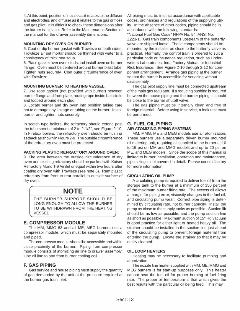
4. At this point, position of nozzle as it relates to the diffuser and electrodes, and diffuser as it relates to the gas orif ces and gas pilot. It is diff cult to check these dimensions after the burner is in place. Refer to the Maintenance Section of the manual for the drawer assembly dimensions.
MOUNTING DRY OVEN ON BURNER:5. Coat or dip burner gasket with Trowleze on both sides. Trowleze air set mortar should be thinned with water to a consistency of thick pea soup.6. Place gasket over oven studs and install oven on burner f ange. Oven must be centered around burner blast tube. Tighten nuts securely. Coat outer circumference of oven with Trowleze.
MOUNTING BURNER TO HEATING VESSEL:7. Use rope gasket (not provided with burner) between burner f ange and front plate, routing rope inside bolt circle and looped around each stud.8. Locate burner and dry oven into position taking care not to damage any linkage or tubing on the burner. Install burner and tighten nuts securely.
In scotch type boilers, the refractory should extend past the tube sheet a minimum of 2 to 2-1/2", see Figure 2-10. In Firebox boilers, the refractory oven should be f ush or setback as shown in Figure 2-9. The outside circumference of the refractory oven must be protected.
PACKING PLASTIC REFRACTORY AROUND OVEN:9. The area between the outside circumference of dry oven and existing refractory should be packed with Kaiser Refractory Mono T-9 AirSet or equal within two hours after coating dry oven with Trowleze (see note 6). Ram plastic refractory from front to rear parallel to outside surface of dry oven.
E. COMPRESSOR MODULE The MM, MMG 63 and all ME, MEG burners use a compressor module, which must be separately mounted and piped. The compressor module should be accessible and within close proximity of the burner . Piping from compressor module consists of atomizing air line to drawer assembly, lube oil line to and from burner cooling coil.
F. GAS PIPING Gas service and house piping must supply the quantity of gas demanded by the unit at the pressure required at the burner gas train inlet.
THE BURNER SUPPOR T SHOULD BE LONG ENOUGH TO ALLOW THE BURNER TO BE WITHDRAWN FROM THE HEATING VESSEL
NOTE
All piping must be in strict accordance with applicable codes, ordinances and regulations of the supplying util-ity. In the absence of other codes, piping should be in accordance with the following standards:"National Fuel Gas Code" NFPA No. 54, ANSI No. Z223-1. Gas train components upstream of the butterf y valve are shipped loose. These components should be mounted by the installer as close to the butterf y valve as practical. Normally, the control train is ordered to suit a particular code or insurance regulation, such as Under-writers Laboratories, Inc., Factory Mutual, or Industrial Risk Insurance. See Figure 2-10 through 2-12 for com-ponent arrangement. Arrange gas piping at the burner so that the burner is accessible for servicing without disassembly. The gas pilot supply line must be connected upstream of the main gas regulator. If a reducing bushing is required between the house piping and the burner piping, it should be close to the burner shutoff valve. The gas piping must be internally clean and free of foreign material. Before using in service, a leak test must be performed.
G. FUEL OIL PIPINGAIR ATOMIZING PIPING SYSTEMS MM, MMG, ME and MEG models use air atomization. These burners use a separately driven burner mounted oil metering unit, requiring oil supplied to the burner at 10 to 15 psi on MM and MMG models and up to 20 psi on ME, and MEG models. Since the scope of this manual is limited to burner installation, operation and maintenance, pipe sizing is not covered in detail. Please consult factory for more information.
CIRCULATING OIL PUMP A circulating pump is required to deliver fuel oil from the storage tank to the burner at a minimum of 150 percent of the maximum burner f ring rate. The excess oil allows a margin for piping error, viscosity changes in the fuel oil, and circulating pump wear . Correct pipe sizing is deter-mined by circulating rate, not burner capacity. Install the pump as close to the supply tanks as possible. Suction lift should be as low as possible, and the pump suction line as short as possible. Maximum suction of 15" Hg vacuum is good practice for either light or heated heavy oil. The strainer should be installed in the suction line just ahead of the circulating pump to prevent foreign material from entering the pump. Locate the strainer so that it may be easily cleaned.
OIL LOOP HEATERS Heating may be necessary to facilitate pumping and atomization. The nozzle line heater supplied with MM, ME, MMG and MEG burners is for start-up purposes only . This heater cannot heat the fuel oil for proper burning at fuel f ring rate. The proper oil temperature is that which gives the best results with the particular oil being f red. This may

Sec1:14
vary widely with different fuels in different f ring systems. Residual oil viscosity can vary widely within grade limits and is not always within the specif ed limits for the grade. Fuel viscosity requirements for air atomizing burners are not critical. Under typical circumstances a viscosity of 100 SSU might be optimum, but good results may be obtained up to 150 SSU. There is no advantage to less than 100 SSU. Where the burning characteristics of the fuel are un-known, the following may be considered as typical: No. 4 80° -125°F
No. 5L 115° -160°F
No. 5H 145° -180°F
No. 6 180° -220°F
H. INSTALLATION CHECKLIST1. All burners are carefully assembled and tested at the factory, but before being placed in service all connectors should be checked again for loose-ness caused during shipment.
Check: a. Electrical terminals in the control panel and on all electrical components. b. Piping fittings and unions. c. Tubing connections. d. Nuts, bolts, screws.
2. Before operating pumps, metering heads and compres-sors, make certain that reservoirs are properly filled with the Specified lubricant. Open all necessary oil shutof f valves. Do not run compressors, pumps, or metering units without oil.
3. Before connecting electrical current to any component, be sure the supply voltage is the same as that specified on component nameplate.
4. Before burner operation, be sure all motors are rotating in the proper direction.
5. Before firing, make sure that the refractory flame cone is properly sealed to the burner mounting flange and the boiler front plate.
6. Make certain that the operator in charge is properly instructed in operation and maintenance procedures.
CAUTIONLUBRICATIN OIL IS DRAINED FROM THE AIR OIL TANK BEFORE SHIPMENT . BEFORE ATTEMPTING T O START THE BURNER, ADD OIL TO THE RECOMMENDED LEVEL.
CAUTIONTHE BURNER REFRACTORY CONE IS AIR-CURED ONLY. HEA T-CURING MUST BE INITIA TED AT INITIAL START-UP. RUN THE BURNER AT LOW FIRE FOR A PERIOD OF 6 TO 8 HOURS BEFORE STARTING TO GRADUALLY INCREASE THE FIRING RATE. FAILURE TO DO SO WILL RESULT IN DAMAGE AND CRACKS IN THE REFRACTORY.

Sec1:15
Figure 2-11TYPICAL U.L. GAS PIPING LAYOUT MODEL M 14-25
Figure 2-12TYPICAL U.L. GAS PIPING LAYOUT MODEL M 28-42
Figure 2-13TYPICAL U.L. GAS PIPING LAYOUT MODEL M 54-105

Sec1:16
Figure 2-14

Sec1:17
Figure 2-15

Sec1:18
Figure 2-16

Sec1:19
CHAPTER 3 OPERATION
A. PREPERATION FOR INITIAL START-UP ALL FUELS When the installation is complete and all electrical, fuel, water and vent stack connections are made, make certain said connections are tight. The operator should become familiar with the burner , boiler controls and components. To identify controls and components refer to photographs and contents of Chapter 1. Adjustment procedures given in Chapter 4 should be revised prior to f ring. The wiring diagram should also be studied along with the operating sequence of burner programmer. Read and understand starting instructions before at-tempting to operate the burner. Before attempting to start the burner, the following checks must be made:
BOILER Check the boiler water level. Be sure all boiler valves are installed correctly and positioned properly . Set the high limit control sightly above the operating control. Set operating control at the desired temperature or pressure.
BURNER Check the electrical power supply to the burner in ac-cordance with the nameplate voltage on all motors and the control circuit. Check motor rotation by momentarily closing the starter or relay. Blower impeller rotation is clockwise when viewed from the back of the burner. Air compressor and metering unit rotation is clockwise when viewed from its drive end. Open the housing and check the electrode setting. For protection in shipment, the f ame safeguard control chassis is shipped unmounted. Check all screw connec-tions before attaching f ame safeguard chassis to base. Screw must be secure to assure low resistance connec-tions. The relay chassis is mounted on the subbase with a screw which, when tightened, completes the connection between the subbase and chassis contacts. Press manual reset button to be sure safety switch contacts are closed. Check control linkage for proper movement of the air volume damper and fuel metering components. This can be done by loosening the linkage at the actuator level and manipulating by hand. Check the air shutter and adjust low f re setting.
B. FIRING PREPARATIONS FOR GAS BURNERS A representative of the gas utility should turn on the gas. Determine by a test gauge upstream of the burner regulator that suff cient pressure exists at the entrance to the gas train. The gas pressure regulator must be adjusted to the pressure required and the pressure setting recorded. On combination fuel models, set the selector switch to gas. On initial start-up it is recommended that the main gas shutoff cock remain closed until the programmer has cycled through pre-purge and pilot sequences to determine that
the main gas valve opens. Turn the burner switch "OFF" and let programmer f nish its cycle. Check to see that gas valve closes tightly. On burners equipped with high and low gas pressure switches, set switch pressure actuating levels and record settings for future service reference. When the conditions covered above and in Chapter 2 are assured, the burner is ready for f ring. Refer to Section E for starting and operating information.
C. FIRING PREPARATIONS FOR OIL BURNERS. Prior to initial f ring, oil f ow pressure and temperature should be verif ed. On MM and ME models, inspect the lube oil sump level. Add oil to bring the oil level to the midpoint or slightly higher in the reservoir sight glass. Check the oil level in the compressor air intake strainer. Make certain that the drive belts or couplings are aligned and properly adjusted. To verify air f ow and pressure, momentarily f ip the switch "ON" and immediately turn "OFF". The programmer will continue through its cycle, however , without ignition or energizing the fuel valves. Observe the air pressure gauge. With compressor running and no oil f ow, the pres-sure should be approximately 10 psi. The schematic f ow diagram(s), Figure 1-7 and Figure 1-8, indicates the f ow of fuel and atomizing air. If the burner is a dual fuel model, make certain that the main gas shutoff cock is closed and the fuel selector switch set to "OIL".
OIL FLOW LIGHT OIL. Refer to Figure 2-13. Open all valves in the oil suction and return line. The burner oil metering units are not capable of creating suction. Fuel oil must be supplied to the metering unit at a nominal 10 to 15 psi pressure by a circulating supply pump. HEAVY OIL. Refer to Figures 2-14 and 2-15, for burn-ers using heavy oil. Note the by-pass valve between the supply and return lines. At initial system start-up or after prolonged shutdown, start the system as follows:
1. A vacuum (or compound pressure-vacuum) gauge should be installed in the oil suction line, and its reading noted. This gauge indicates the tightness of the suction system.
SEE DIRECTIONS FOR "OIL TEMPERATURE" AS OUTLINED IN SECTION C. THOSE PREPARATIONS MUST BE ACCOMPLISHED SIMULTANEOUSLY DURING OIL FLOW AND PRESSURE ESTABLISHMENT.
NOTE

Sec1:20
2. Open valve No. 1 in the bypass line and close valve No. 2 in the supply line to the metering pump.
3. Turn on the pre-heater and the circulating pump. Oil will circulate from the tank through the circulating pump and pre-heater, returning to the tank through the bypass and return lines. Observe the oil supply pressure gauge for indication that oil f ow is established. If no pressure shows after a few moments, and the vacuum gauge shows little or no suction, stop the circulating pump and re-prime. Heavy oil in the storage tank (i.e. hot well) must be warm enough to permit f ow.
4. As the system becomes warm, the pressure required for circulation will gradually drop. When the return is warm, open No. 2 valve and throttle the f ow in the bypass line with valve No. 1. This will cause the oil to f ow through the back pressure valve to the tank via the return line. The pressure in this loop around the burner should not exceed 20 psi (15 psi on MM models). When the loop around the burner becomes warm, gradually close valve No. 1 in the bypass line. All supply oil will then f ow through the burner loop.
OIL PRESSURE The system pressure is regulated by the back pressure valve. This should be set between 10-15 psi (MM mod-els) or 12-20 psi (ME models) at the burner inlet after the temperature stabilizes.
OIL TEMPERATURE Heavy oil f ow and burning characteristics are dependent on oil viscosity, which in turn requires temperature regula-tion. A loop heater in the supply line between the circulating pump and the burner heats the oil. The loop heater should be adjusted to give the designed operating temperature. Where the burning characteristics of the fuel are unknown, the following may be considered as typical:
No. 4 80° -125°F No. 5L 115° -160°F No. 5H 145° -180°F No. 6 180° -220°F
If conditions do not permit the loop heater to develop the required temperature, the nozzle line heater on the
burner should be depended upon only to raise the oil to the atomizing temperature during the initial low f re start. The nozzle line heater is intended to supply heated oil at a rate no greater than that required for low f re. In nomi-nal operation the nozzle line thermostat is set lower than the loop oil temperature, so that nozzle line heating is not required except during cold start. When the conditions covered above and in Section A are assured, the burner is ready for f ring. Refer to Section E for starting and operating information.
D. SEQUENCE OF OPERATION The programming control sequences the operation of all controls and components through the starting, ignition, f ring, and shutdown cycle. The burner and control system are in starting condition when:a. The operating and high limit control (temperature or pressure) are below their cutoff setting;b. All power supply switches are closed;c. Power is present at the control panel. Refer to the manufacturers literature on programming controls and burner wiring diagrams for detailed informa-tion.
E. START-UP AND OPERATING GAS BURNERS Close the main and pilot gas cocks. Make sure the "ON-OFF" switch is in the "OFF" position and the fuel selector switch on "GAS". Actuate the manual reset button of the f ame safeguard control to close the safety switch contacts. Set the "MANUAL-AUTO" switch in the "MANUAL" position. Set the manual potentiometer in low f re position. Open the gas pilot cock. Set the "ON-OFF" switch to "ON". The burner will start and pre-purge. After pre-purge, the ignition transformer and the gas pilot solenoid are energized. Before pro-ceeding conduct electrical interference and pilot turn-down tests if not previously done. Refer to Chapter 4, Section C and D. On initial start-up it is recommended that the main gas shutoff cock remain closed until the programmer has cycled through pre-purge and pilot sequence. Then determine that main gas valve opens. When this is con-f rmed, turn the burner switch "OFF" and let programmer f nish its cycle. Check to see that gas valve has closed tightly. If ignition does not occur, turn the burner switch "OFF" and allow programmer to recycle for a new ignition trial. Turn burner "ON" and after pilot ignition when the f ame relay pulls in, the slow opening, motorized, main gas valve is energized. Slowly open the downstream manual shutoff gas cock. Main f ame should ignite at this time. The gas valve and air damper continue advancing until high f re is reached. Do not repeat unsuccessful light off attempts without rechecking burner and pilot adjustment. Vent fuel vapors from the combustion chamber after each unsuccessful light off attempt. Set the gas low f re rate by adjusting
FUEL OIL OF ANY GRADE MAY VARY NECESSITATING A HIGHER OR LOWER TEMPERATURE. THE BEST VISCOSITY OF THE OIL AT THE NOZZLE IS USUALLY 100-150 SSU. THE BEST TEMPERATURE OF THE OIL AT THE BURNER IS DETERMINED BY FLAME CHARACTERISTICS AND COMBUSTION RESULTS.
NOTE
Sec1:21
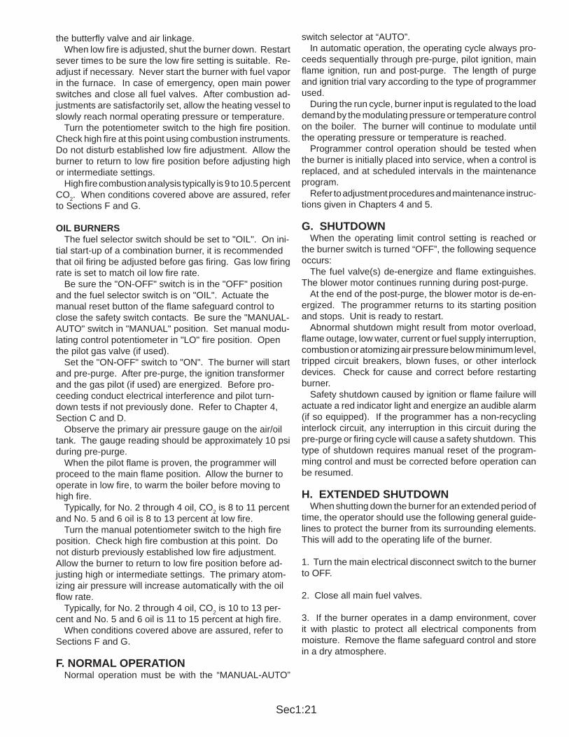
the butterf y valve and air linkage. When low f re is adjusted, shut the burner down. Restart sever times to be sure the low f re setting is suitable. Re-adjust if necessary. Never start the burner with fuel vapor in the furnace. In case of emergency , open main power switches and close all fuel valves. After combustion ad-justments are satisfactorily set, allow the heating vessel to slowly reach normal operating pressure or temperature. Turn the potentiometer switch to the high f re position. Check high f re at this point using combustion instruments. Do not disturb established low f re adjustment. Allow the burner to return to low f re position before adjusting high or intermediate settings. High f re combustion analysis typically is 9 to 10.5 percent CO2. When conditions covered above are assured, refer to Sections F and G.
OIL BURNERS The fuel selector switch should be set to "OIL". On ini-tial start-up of a combination burner, it is recommended that oil f ring be adjusted before gas f ring. Gas low f ring rate is set to match oil low f re rate. Be sure the "ON-OFF" switch is in the "OFF" position and the fuel selector switch is on "OIL". Actuate the manual reset button of the f ame safeguard control to close the safety switch contacts. Be sure the "MANUAL-AUTO" switch in "MANUAL" position. Set manual modu-lating control potentiometer in "LO" f re position. Open the pilot gas valve (if used). Set the "ON-OFF" switch to "ON". The burner will start and pre-purge. After pre-purge, the ignition transformer and the gas pilot (if used) are energized. Before pro-ceeding conduct electrical interference and pilot turn-down tests if not previously done. Refer to Chapter 4, Section C and D. Observe the primary air pressure gauge on the air/oil tank. The gauge reading should be approximately 10 psi during pre-purge. When the pilot f ame is proven, the programmer will proceed to the main f ame position. Allow the burner to operate in low f re, to warm the boiler before moving to high f re. Typically, for No. 2 through 4 oil, CO2 is 8 to 11 percent and No. 5 and 6 oil is 8 to 13 percent at low f re. Turn the manual potentiometer switch to the high f re position. Check high f re combustion at this point. Do not disturb previously established low f re adjustment. Allow the burner to return to low f re position before ad-justing high or intermediate settings. The primary atom-izing air pressure will increase automatically with the oil f ow rate. Typically, for No. 2 through 4 oil, CO2 is 10 to 13 per-cent and No. 5 and 6 oil is 11 to 15 percent at high f re. When conditions covered above are assured, refer to Sections F and G.
F. NORMAL OPERATION Normal operation must be with the “MANUAL-AUT O”
switch selector at “AUTO”. In automatic operation, the operating cycle always pro-ceeds sequentially through pre-purge, pilot ignition, main f ame ignition, run and post-purge. The length of purge and ignition trial vary according to the type of programmer used. During the run cycle, burner input is regulated to the load demand by the modulating pressure or temperature control on the boiler. The burner will continue to modulate until the operating pressure or temperature is reached. Programmer control operation should be tested when the burner is initially placed into service, when a control is replaced, and at scheduled intervals in the maintenance program. Refer to adjustment procedures and maintenance instruc-tions given in Chapters 4 and 5.
G. SHUTDOWN When the operating limit control setting is reached or the burner switch is turned “OFF”, the following sequence occurs: The fuel valve(s) de-energize and f ame extinguishes. The blower motor continues running during post-purge. At the end of the post-purge, the blower motor is de-en-ergized. The programmer returns to its starting position and stops. Unit is ready to restart. Abnormal shutdown might result from motor overload, f ame outage, low water, current or fuel supply interruption, combustion or atomizing air pressure below minimum level, tripped circuit breakers, blown fuses, or other interlock devices. Check for cause and correct before restarting burner. Safety shutdown caused by ignition or f ame failure will actuate a red indicator light and energize an audible alarm (if so equipped). If the programmer has a non-recycling interlock circuit, any interruption in this circuit during the pre-purge or f ring cycle will cause a safety shutdown. This type of shutdown requires manual reset of the program-ming control and must be corrected before operation can be resumed.
H. EXTENDED SHUTDOWN When shutting down the burner for an extended period of time, the operator should use the following general guide-lines to protect the burner from its surrounding elements. This will add to the operating life of the burner.
1. Turn the main electrical disconnect switch to the burner to OFF.
2. Close all main fuel valves.
3. If the burner operates in a damp environment, cover it with plastic to protect all electrical components from moisture. Remove the f ame safeguard control and store in a dry atmosphere.

Sec1:23
A. GENERAL While each burner is tested at the factory for correct operation before shipment, variable conditions such as burning characteristics of the fuel used and operating load conditions may require further adjustment after installation to assure maximum operating eff ciency. Prior to placing the boiler into initial service, a complete inspection should be made of all controls, connecting piping, wiring and all fastenings such as nuts, bolts and setscrews to be sure that no damage or misadjustments occurred during shipping and installation. A combustion eff ciency analysis made during the initial start-up will help to determine what additional adjustments are required in a particular installation.
B. COMBUSTION ADJUSTMENT ON GAS AND OIL Ef f cient combustion cannot be properly judged by f ame appearance, although it may help in making preliminary settings. The proper settings of air-fuel ratios must be determined by f ue gas analysis. Combustion gas analysis indicatesthe air to fuel ratio and the degree of complete combustion.Instruments are available to measure carbon dioxide (CO2), oxygen (O2), and carbon monoxide (CO).
STACK TEMPERATURE Net stack temperature is obtained by subtracting the ambient temperature from the f ue gas temperature. A high net stack temperature indicates wasted heat. Stack temperature should be as low as possible without causing f ue gas condensation. Stack heat loss can be reduced by decreasing either the temperature or the volume of the f ue gas, or both. Flue gas temperature is reduced by improving heat transfer or by reducing excess combustion air . A certain amount of excess air is necessary to complete combustion. More eff cient burners require minimum excess air.
SMOKE MEASUREMENT Smoke measurements can be made using a variety of different methods. The standards will vary somewhat according to the equipment used, and instructions accom-panying the instrument should be followed. Smoky combustion can result from: Improper air delivery, insuff cient draft, improper fuel viscosity, improper fuel-air
CHAPTER 4 ADJUSTMENTS
ratio, excessive air leaks in the combustion chamber , or improper fuel oil temperature.
GAS ADJUSTMENTS Low f re combustion analysis typically is 7 to 9 percent CO2 and less than .04 percent CO (400 ppm). High f re reading typically is 9 to 10.5 percent CO 2 and less than .04 percent CO.
FUEL OIL ADJUSTMENTSAdjust for a “clean f re”. Typically for No. 2 through 4 oil, CO2 is 8 to 11 percent at low f re and 10 to 13 percent at high f re. No. 5 and 6 oil, CO2 is 8 to 13 percent at low f re and 11 to 15 percent at high f re.
C. ELECTRICAL INTERFERENCE TEST Prior to putting the burner into service, conduct the fol-lowing test to ascertain that ignition spark will not cause the f ame relay to pull in.
GAS FIRED Close the pilot and main line manual gas valves. Start the burner and at time of pilot trial with just the electrical ignition system energized, the f ame relay should not pull in (i.e. be energized). Upon completion of successful test, proceed with start-up procedures.
OIL FIRED Disconnect the electrical power to the burner. Disconnect the electric oil safety shutoff valve. Reconnect electric power. Close the pilot line manual gas valve, if used. Start burner and at the time of pilot trial, with just the electrical ignition system energized, the f ame relay should not pull in. Upon completion of successful test, disconnect power supply. Reconnect oil safety shutof f valve and turn on manual pilot gas valve. Reconnect power supply and proceed with start-up procedures.
D. GAS SYSTEMGAS PRESSURE Gas must be supplied at a pressure high enough to overcome the pressure loss in the burner gas train and furnace pressure while running at full input. Refer to name-
WHEN RESIDUAL OILS ARE USED, MAKE FIRE ADJUSTMENTS AFTER FUEL REACHES PROPER TEMPERATURE
NOTESOME CONDIT IONS MA Y MAKE IT IMPOSSIBLE TO A TTAIN ACCURA TE COMBUSTION ANALYSIS. AIR INFILTRATION THROUGH THE BOILER AT ANY POINT WILL DILUTE FLUE GAS.
NOTE
Sec1:24
plate inside control panel for gas pressure requirements at train inlet and manifold. The pressures listed are based on nominal 1000 Btu/cu ft natural gas at elevations up to 2000 feet above sea level.
GAS FLOWThe volume of gas is measured in cubic feet as determined by a meter reading. The gas f ow rate required depends on the heating value (Btu/cu ft). The supplying utility can provide this information as well as pressure correction factors. To determine the required number of cubic feet per hour of gas, divide burner input (Btu/hr) by the heating value (Btu/cu ft).
GAS PILOT FLAME ADJUSTMENT The gas is regulated by adjusting the pressure setting of the pilot regulator. Normal setting is 3" to 6" WC when the pilot is burning. The f ame must be suff cient to be proven by the f ame detector and ignite the main f ame. Although it is possible to visibly adjust the size of the pilot f ame, obtain a proper DC volt or microamp reading of the f ame signal. The f ame safeguard amplif er has a meter jack for this purpose. At initial start-up and during planned maintenance, test the pilot f ame signal, pilot turndown, and safety switch lockout.
MAIN GAS PRESSURE REGULATOR The gas pressure required at the burner manifold is the pressure that is required to f re the burner at its rated capcity. The gas pressure regulator must be adjusted to achieve this pressure full input. Refer to manufacturer's literature for regulator adjustment.
LOW GAS PRESSURE SWITCH (28-105) Turn adjusting screw until indicator moves to a pressure setting slightly below the maximum operating gas pressure. The control will break a circuit if pressure is below this value. The control should be adjusted to prevent operation with excessive gas pressure, but not at a pressure so close to
normal operating pressure that unnecessary shutdowns occur.This switch must be manually reset after tripping. To reset, allow gas pressure to drop and press the manual reset button.
HIGH GAS PRESSURE SWITCH (28-105) Turn adjusting screw until indicator moves to a pressure setting slightly above the maximum operating gas pressure. The control will break a circuit if pressure exceeds this value. The control should be adjusted to prevent operation with excessive gas pressure, but not at a pressure so close to normal operating pressure that unnecessary shutdowns occur.This switch must be manually reset after tripping. To reset, allow gas pressure to drop and press the manual reset button.
GAS COMBUSTION ADJUSTMENT After operating for a suf f cient period of time to assure a warm boiler, make adjustments for most ef f cient com-bustion.The butterf y gas valve directly controls the rate of f ow. The low f re light-off setting should be regarded as preliminary until proper gas pressure for high f re operation is established. Determine the actual gas f ow from a meter reading at high f re. With the butterf y valve open and with regulated gas pressure set, the actual f ow rate should be quite close to the required input. If corrections are necessary, increase or decrease the gas pressure by adjusting the gas pressure regulator, following manufacturer’s directions for regulator adjustment. When proper gas f ow is obtained, take a f ue gas analysis reading. With the high f re air-fuel ratio established, the gas pres-sure regulator needs no further adjusting. Recheck low f re and adjust if necessary. Proper setting of the air/fuel ratios at all rates must be determined by combustion analysis.
E. OIL SYSTEMOIL METERING UNIT Fuel oil supply to the integral metering unit must be 10-15 psi and up to 20 psi on separate metering units. The oil spray should ignite as soon as the oil solenoid valve opens. If the oil spray fails to ignite, move the metering unit adjustment lever a few degrees counterclockwise. This increases the amount of oil at low f re and makes ignition easier; it will also increase the oil on high f re, so this must be checked later. Once adjusted, the pump should opearte with a minimum amount of adjustment. If a burner failure is caused by the oil metering pump, check the following:1. See that the oil tanks are not empty.2. That all oil valves between the burner and the tank are open and that the suction line is not airbound.3. That the low f re setting has not been disturbed.4. That there is pressure at the integral metering unit but not to exceed 15 psi (20 psi on separate metering unit).5. That the pump turns freely.
WARNINGAN ULTRA-VIOLET FLAME SENSOR ELECTRI-CAL SPARK INTERFERENCE TEST MUST BE PERFORMED AFTER FINAL ADJUSTMENT. SEE SECTION C OF THIS CHAPTER FOR ADDITIONAL INFORMATION.
WHEN CHECKING THE INPUT RA TE, MAKE SURE NO OTHER EQUIPMENT IS OPERATING ON THE SAME METER
NOTE
Sec1:25
6. Check for a clogged strainer at the suction side of the circulating pump.7. Check for a dirty burner strainer.8. Check for a plugged or carboned nozzle. This will show up as excessive primary air pressure. 9. That the oil by-pass valve is not by-passing the metered fuel oil.Internal wear of the pump may take place due to the pres-ence of dirt in the oil and in time this will result in excessive clearances which reduces the pump capacity. If the oil metering pump fails to deliver capacity or meters erratically, replace the oil and air pump as a unit and return the oil pump for repair or exchange (where allowed).
ATOMIZING AIR PRESSURE Atomizing air in the air/oil tank is regulated by adjusting the valve in the return air line on integral metering units or in the air inlet on air compressor module burners. The air pressure is indicated by the pressure gauge at the air/oil tank. A minimum of 10 psi air pressure in low f re is suggested. As the f ring rate increases, the air pressure also increases. Air pressure will be less with light oils. If any change in atomizing air pressure is made, check the ignition several times for reliable light off. Adjustments should be set to obtain reliable ignition with best low and high f re combustion results. If the required atomizing air pressure cannot be main-tained, a lack of lubricating oil may be the cause or the intake f lter may be dirty.
ATOMIZING AIR PROVING SWITCH The knurled nut between the switch and bellows is turned in to raise pressure setting. The minimum amount of atom-izing air is during pre and post purge. During pre purge, adjust switch until it breaks the circuit. Readjust switch above this circuit break point to actuate under a condition of minimum pressure, but not so close as to cause nuisance shutdowns.
NOZZLE LINE HEATER
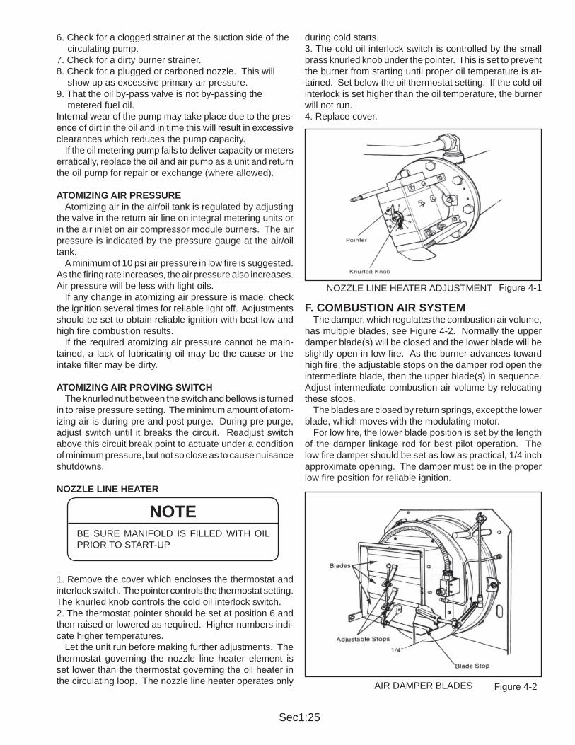
1. Remove the cover which encloses the thermostat and interlock switch. The pointer controls the thermostat setting. The knurled knob controls the cold oil interlock switch. 2. The thermostat pointer should be set at position 6 and then raised or lowered as required. Higher numbers indi-cate higher temperatures. Let the unit run before making further adjustments. The thermostat governing the nozzle line heater element is set lower than the thermostat governing the oil heater in the circulating loop. The nozzle line heater operates only
during cold starts.3. The cold oil interlock switch is controlled by the small brass knurled knob under the pointer. This is set to prevent the burner from starting until proper oil temperature is at-tained. Set below the oil thermostat setting. If the cold oil interlock is set higher than the oil temperature, the burner will not run.4. Replace cover.
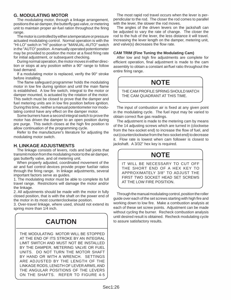
F. COMBUSTION AIR SYSTEM The damper, which regulates the combustion air volume, has multiple blades, see Figure 4-2. Normally the upper damper blade(s) will be closed and the lower blade will be slightly open in low f re. As the burner advances toward high f re, the adjustable stops on the damper rod open the intermediate blade, then the upper blade(s) in sequence. Adjust intermediate combustion air volume by relocating these stops. The blades are closed by return springs, except the lower blade, which moves with the modulating motor. For low f re, the lower blade position is set by the length of the damper linkage rod for best pilot operation. The low f re damper should be set as low as practical, 1/4 inch approximate opening. The damper must be in the proper low f re position for reliable ignition.
BE SURE MANIFOLD IS FILLED WITH OIL PRIOR TO START-UP
NOTE
Figure 4-1NOZZLE LINE HEATER ADJUSTMENT
Figure 4-2AIR DAMPER BLADES
Sec1:26
G. MODULATING MOTOR The modulating motor, through a linkage arrangement, positions the air damper, the butterf y gas valve, or metering unit to maintain proper air-fuel ration throughout the f ring range. The motor is controlled by either a temperature or pressure actuated modulating control. Normal operation is with the "HI-LO" switch in "HI" position or "MANUAL-AUTO" switch in the "AUTO" position. A manually operated potentiometer may be provided to position the motor at a f xed f ring rate for initial adjustment, or subsequent checking. During normal operation, the motor moves in either direc-tion or stops at any position within a 90° range to follow load demand. If a modulating motor is replaced, verify the 90° stroke before installing. The f ame safeguard programmer holds the modulating motor in low f re during ignition and until the main f ame is established. A low f re switch, integral to the motor or damper mounted, is actuated by the rotation of the motor. This switch must be closed to prove that the damper and fuel metering units are in low f re position before ignition. During this time, neither a manual potentiometer nor modu-lating control have any effect on the damper motor. Some burners have a second integral switch to prove the motor has driven the damper to an open position during pre purge. This switch closes at the high f re position to allow continuation of the programming cycle. Refer to the manufacturer's literature for adjusting the modulating motor switch.
H. LINKAGE ADJUSTMENTS The linkage consists of levers, rods and ball joints that transmit motion from the modulating motor to the air damper, gas butterf y valve, and oil metering unit. When properly adjusted, coordinated movement of the air and fuel control devices provide proper fuel/air ratios through the f ring range. In linkage adjustments, several important factors serve as guides. 1. The modulating motor must be able to complete its full travel range. Restrictions will damage the motor and/or the linkage.2. All adjustments should be made with the motor in fully closed position, that is with the shaft on the power end of the motor in its most counterclockwise position. 3. Over-travel linkage, where used, should not extend its spring more than 1/4 inch.
The most rapid rod travel occurs when the lever is per-pendicular to the rod. The closer the rod comes to parallel with the lever, the slower the rod moves. The angles of the driven levers on the jackshaft can be adjusted to vary the rate of change. The closer the rod to the hub of the lever , the less distance it will travel. Increasing the lever length on the damper, metering unit, and valve(s) decreases the f ow rate. CAM TRIM (Fine Tuning the Modulating Cam) After low and high f re adjustments are complete for eff cient operation, f nal adjustment is made to the cam assembly to obtain a constant air/fuel ratio throughout the entire f ring range.
The input of combustion air is f xed at any given point in the modulating cycle. The fuel input may be varied to obtain correct f ue gas readings. The adjustment is made to the metering cam by means of the 14 adjusting screws which are turned in (clockwise from the hex-socket end) to increase the f ow of fuel, and out (counterclockwise from the hex-socket end) to decrease it. Flow rate is lowest when cam follower is closest to jackshaft. A 3/32" hex key is required.
Through the manual modulating control, position the roller guide over each of the set screws starting with high f re and working down to low f re. Make a combustion analysis at each of these set screw points. Adjustment can be made without cycling the burner. Recheck combustion analysis until desired result is obtained. Recheck modulating cycle to assure satisfactory results.CAUTION
THE MODULATING MOTOR WILL BE STOPPED AT THE END OF ITS STROKE BY AN INTEGRAL LIMIT SWITCH AND MUST NOT BE INST ALLED BY THE DAMPER, METERING V ALVE OR FUEL UNITS. DO NOT TURN THE MOT OR SHAFT BY HAND OR WITH A WRENCH. SETTINGS ARE ADJUSTED BY THE LENGTH OF THE LINKAGE RODS, LENGTH OF LEVER ARMS, AND THE ANGULAR POSITIONS OF THE LEVERS ON THE SHAFTS. REFER TO FIGURE 4-5
THE CAM PROFILE SPRING SHOULD MATCH THE CAM QUADRANT AT THIS TIME.
NOTE
IT WILL BE NECESSAR Y TO CUT OFF THE SHOR T END OF A HEX KEY TO APPROXIMATELY 3/8" T O ADJUST THE FIRST TWO SOCKET HEAD SET SCREWS AT THE LOW FIRE POSITION.
NOTE

Sec1:27
Figure 4-4
Figure 4-3FUEL-AIR LINKAGE ADJUSTMENTS
CAM TRIM ADJUSTMENTS

Sec1:29
CHAPTER 5 MAINTENANCE
A. GENERAL A maintenance program avoids unnecessary down time, costly repairs, and promotes safety . It is recommended that a record be maintained of daily, weekly, monthly, and yearly maintenance activities. Electrical and mechanical devices require systematic and periodic inspection and maintenance. Any “automatic” features do not relieve the operator from responsibility, but rather free him from certain repetitive chores, providing time for upkeep and maintenance. Unusual noise, improper gauge reading, leak, sign of overheating, etc., can indicate a developing malfunction, requiring corrective action.
B. CONTROL SYSTEM Most operating controls require very little maintenance beyond regular inspection. Examine electrical connec-tions. Keep the controls clean. Remove any dust from the interior of the control. Covers should be left on controls at all times. Keep the control cabinet doors closed. Dust and dirt can damage motor starters and relay contacts. Starter contacts are plated with silver and are not harmed by discoloration. Never use f les or abrasive materials such as sandpaper on contact points.
PROGRAMMING CONTROL This control requires no adjustment, nor should any at-tempt be made to alter contact settings or timing logic. Those programmers with contacts may require occasional clean-ing. If so, follow instructions given in the manufacturer ’s bulletin. Never use abrasive materials. The manufacturer’s bulletin also contains troubleshooting information. The f ame detector lens should be cleaned as often as condi-
tions demand. A periodic safety check procedure should be established to test the complete safeguard system. Tests should verify safety shutdown with a safety lock out upon failure to ignite the pilot or the main f ame, and upon loss of f ame. Each of these conditions should be checked on a scheduled basis. The safety check procedures are contained in the manufacturer’s bulletin.
MOTORS Motor supply voltage must not vary more than 10 percent from nameplate ratings. At initial start-up and regularly thereafter, check the motor current with an amp meter while the burner is in high f re position. If the reading exceeds the nameplate rating plus service factor, determine the cause and correct it. In dusty locations, clean the motor regularly to assure adequate cooling. Lubricate in accordance with the manufacturer's instructions.
C. COMBUSTION AIR IMPELLER The method if retaining the fabricated impeller on the motor shaft has been revised. This change took ef fect starting with burner serial number A1918. Two set screws directly over the key replaces the retain-ing bolt with washers on the end of the motor shaft and teh single set screw . Spacers are used to maintain the clearance between the motor mounting bolts and impeller which also maintains the correct overlap on the air inlet cone. Refer to Figure 5-1.
IT IS IMPORTANT THAT YOU PROVIDE SUPPORT FOR THE HOUSING WHEN IN THE OPEN POSI-TION T O PREVENT DAMAGE T O THE HINGES AND SUBSEQUENT COMPONENTS.
CAUTION
Figure 5-1
WARNINGANY COVER PLATES, ENCLOSURES, OR GUARDS ANCHORED TO THE BURNER, OR ANY BURNER RELATED EQUIPMENT, MUST REMAIN IN POSITION AT ALL TIMES. ONLY DURING MAINTENANCE AND SERVICE SHUTDOWN CAN THESE COVER PLATES, ENCLOSURES, OR GUARDS BE REMOVED. THEY MUST BE REPLACED, AND SECURELY ANCHORED BEFORE TESTING, ADJUSTING, OR RUNNING THE BURNER OR BURNER RELATED EQUIPMENT.
WHEN REPLACING A CONTROL OR CLEANING CONTACTS, BE SURE TO OPEN THE MAIN POWER SUPPLY SWITCH SINCE THE CONTROL IS "HOT" EVEN THROUGH THE BURNER SWITCH IS OFF. MORE THAN ONE DISCONNECT SWITCH MAY BE REQUIRED TO DISCONNECT ALL POWER.
CAUTION
IMPELLER MOUNTING INSTRUCTIONS
Sec1:30
exchange (where allowed). Do not disassemble.
NOZZLE LINE HEATER Nozzle line heaters damaged by water accumulation, do not qualify for warranty or exchange service. Failure to prevent water accumulation inside the heater manifold constitutes improper care. Completely drain the heater manifold periodically. This should be part of the preventive maintenance program. Maintenance consists primarily of removing the heating element from the manifold and scraping any accumulation of carbonized oil or sludge deposits from the heat exchange surfaces. Before breaking electrical connections to the heating elements, mark all wires and terminals to assure correct replacement of wires. Periodic cleaning is necessary to prevent over heating or burn out of the elements. If operation of the heater becomes sluggish, examine the elements and clean as required. Inspect the manifold each time the heater is removed. Flush all accumulated sludge and sediment before rein-stalling the heater. Heater must be full of oil before power is turned on. AIR COMPRESSOR The air compressor itself requires little maintenance, however its life is dependent upon suf f cient clean, cool lubricating oil. The oil level in the air-oil tank must be checked regularly. Lack of oil will damage the compressor. Disassembly or f eld repairs to the air compressor are not recommended.
LUBRICATING OIL Lubricating oil must be visible in the sight gauge at all times. The oil level should be maintained midway in the sight gauge. SAE 20 non-detergent oil is recommended in a normal operating environment. SAE 30 non-detergent oil should be used in a high temperature environment, and SAE 10 non-detergent oil in a low temperature envi-ronment. Name brands known to perform satisfactorily include Havoline (Texaco), Mobil Oil (Mobil), Shell X100 and Permalube (American). Follow this procedure when adding oil: Adding oil is accomplished through the f ll pipe on the side of the air-oil tank. The compressor (burner) must be shut off during f lling.
D. GAS SYSTEMMOTORIZED MAIN GAS VALVES Should the valve fail to operate, check for voltage at the valve. Make certain that the main shutoff cock is closed prior to testing. The actuator is not f eld repairable nor should it be disassembled. Replace the actuator if the valve fails to operate. After replacement, cycle the valve with the fuel shutoff to determine that it opens and closes. If the valve has a visual indicator, observe its position for correct opera-tion.
SOLENOID VALVES A slight hum from the solenoid is normal when the coil is energized. Should the valve fail to operate, check that there is voltage at the valve coil. If there is no voltage at coil, check for loose wiring connections. If there is proper voltage at the valve coil and the valve still fails to open, replace the coil. Refer to manufacturer’s bulletin for correct procedure in coil replacement. Should it become necessary to replace the complete valve, be sure that the f ow is in the drection of the arrow on the body. Test for gas leaks and check valve action several times to ensure proper operation before attempting to relight burner.
E. OIL SYSTEMOIL METERING UNITS: The oil metering unit is a precisely built unit. Internal wear due to dirt in the oil can occur and may in time result in reduced capacity. If burner failure appears to be caused by the metering unit, check the following: 1. See that the oil level is proper in both fuel oil tank and air-oil tank. 2. Make sure all valves between the fuel oil tank and the burner are open. 3. Be sure the oil suction line is not air bound and check the suction line strainer to see that it is not plugged. 4. Check the low f re setting of the metering pump to be sure it is properly set. 5. Make sure the pump turns. 6. Inspect for clogged nozzle.
When an oil metering pump is proven faulty, order a replacement unit and return the old pump for repair or
AN IMPELLER PULLER TOOL, PART NUMBER 632-1856, IS AVAILABLE FOR REMOVING THE FABRICATED IMPELLER.
NOTE
ALL POWER MUST BE DISCONNECTED BEFORE SERVICING THE VALVES.
NOTE
NEVER ADD LUBE OIL THROUGH THE AIR INLET TO THE COMPRESSOR. THE LUBRICATING OIL SHOULD BE CHANGED EVERY 2000 HOURS OR ANNUALLY. SPIN ON LUBE OIL FILTER. FILTER (PART NUMBER 843-106) SHOULD BE REPLACED EVERY 2000 HOURS OR ANNUALLY.
CAUTION

Sec1:31
OIL LEVEL SIGHT GAUGE The oil level sight gauge can be cleaned by removing it from the air-oil tank and soaking it in a detergent solu-tion. If cleaning the gauge proves unsatisfactory, replace it. Compressor Inlet Oil Strainer (Lube Oil Strainer). The lube oil strainer prevents foreign materials from entering the compressor. The strainer screen must be cleaned at regular intervals. The screen is easily removed for cleaning by unscrew-ing the bottom plug. Immerse in solvent and thoroughly clean.
AIR CLEANER Never operate the compressor without the air cleaner in place. The cleaner should be cleaned at regular intervals. The correct oil level must be maintained in the air cleaner. Use the same oil used for air compressor lubrication.
LUBE OIL COOLING COIL The f ns on the tubing must be kept clean and free of dust or dirt.
MOTOR Keep the motor clean. Motor lubrication should follow manufacturer's recommnedations. Check coupling/ sheave alignment frequently and replace coupling insert/belt as required. Keep cover plate or belt guard in place.
SHEAVE ALIGNMENT AND BELT TIGHTENING ME, MEG. Alignment of the compressor and motor sheaves and proper belt tension are important. Figure 5-3 shows how to check parallel alignment of the sheaves. Belt tension is adjusted according to the displacement on the belt with thumb pressure. This displacement should be 3/8 to 1/2 inch. To adjust, loosen the two bolts on the compressor mounting f ange and the three set screws which hold teh compressor in place. The mounting f ange is slotted at the top, which permits belt tightening. If the slot in the mounting f ange is insuf-f cient for obtaining proper belt tension, teh modular base has two extra holes for this purpose. Move the top bolt to the next hole and adjust. Tighten bolts and setscrews. Replace belt guards. If belt becomes frayed or cracked, replace it.
F. BURNER HEAD The burner head can be serviced through the throat of the blast tube on all models by opening the "swing away" air handling section. The procedure for service and inspection of the burner head on models 14-105 burners through the blast tube is as follows:
AIR-OIL TANK A wire mesh f lter is used in this tank to separate the lube oil from the compressed air . Figure 5-2 shows the tank and the location of the f lter. This f lter is very important and should be replaced if dirty. The following procedure will apply: 1. Turn burner off 2. Remove air piping from the cap 3. Remove the cap 4. Remove f lter and wash thoroughly in kerosene or install new f lter 5. Flush tank 6. Insert the f lter 7. Install cap and connect piping
THE MAINTENANCE INTERVALS ON THE COMPRES-SOR MODULE COMPONENTS ARE AFFECTED BY THE ENVIRONMENT IN WHICH THE EQUIPMENT IS PLACED. THE "REGULAR INTER VALS" OR "AS REQUIRED" MAINTENANCE REQUIREMENTS MA Y BE DAILY, WEEKLY, OR MONTHLY, DEPENDING ON THE ENVIRONMENT AND THE OPERA TING TIME OF THE EQUIPMENT. FOLLOW THE PREVENTIVE MAINTENANCE SCHEDULE SHOWN IN SECTION J OR DEVELOP YOUR OWN MAINTENANCE PROGRAM.
CAUTION
Figure 5-2AIR-OIL TANK FILTER
Figure 5-3SHEAVE ALIGNMENT
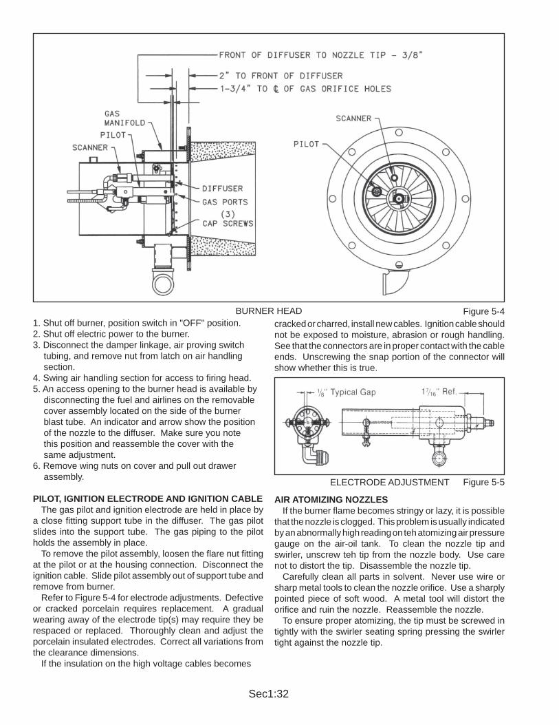
Sec1:32
1. Shut off burner, position switch in "OFF" position.2. Shut off electric power to the burner.3. Disconnect the damper linkage, air proving switch tubing, and remove nut from latch on air handling section.4. Swing air handling section for access to f ring head.5. An access opening to the burner head is available by disconnecting the fuel and airlines on the removable cover assembly located on the side of the burner blast tube. An indicator and arrow show the position of the nozzle to the diffuser. Make sure you note this position and reassemble the cover with the same adjustment.6. Remove wing nuts on cover and pull out drawer assembly.
PILOT, IGNITION ELECTRODE AND IGNITION CABLE The gas pilot and ignition electrode are held in place by a close f tting support tube in the dif fuser. The gas pilot slides into the support tube. The gas piping to the pilot holds the assembly in place. To remove the pilot assembly, loosen the f are nut f tting at the pilot or at the housing connection. Disconnect the ignition cable. Slide pilot assembly out of support tube and remove from burner. Refer to Figure 5-4 for electrode adjustments. Defective or cracked porcelain requires replacement. A gradual wearing away of the electrode tip(s) may require they be respaced or replaced. Thoroughly clean and adjust the porcelain insulated electrodes. Correct all variations from the clearance dimensions. If the insulation on the high voltage cables becomes
cracked or charred, install new cables. Ignition cable should not be exposed to moisture, abrasion or rough handling. See that the connectors are in proper contact with the cable ends. Unscrewing the snap portion of the connector will show whether this is true.
AIR ATOMIZING NOZZLES If the burner f ame becomes stringy or lazy, it is possible that the nozzle is clogged. This problem is usually indicated by an abnormally high reading on teh atomizing air pressure gauge on the air-oil tank. To clean the nozzle tip and swirler, unscrew teh tip from the nozzle body . Use care not to distort the tip. Disassemble the nozzle tip. Carefully clean all parts in solvent. Never use wire or sharp metal tools to clean the nozzle orif ce. Use a sharply pointed piece of soft wood. A metal tool will distort the orif ce and ruin the nozzle. Reassemble the nozzle. To ensure proper atomizing, the tip must be screwed in tightly with the swirler seating spring pressing the swirler tight against the nozzle tip.
Figure 5-4BURNER HEAD
Figure 5-5ELECTRODE ADJUSTMENT

Sec1:33
FLAME SCANNER The scanner must be clean. Even a small amount of contamination will reduce the f ame signal. Wipe the scanner lens with a clean soft cloth.
DIFFUSER The diffuser is factory set and does not require attention under normal operating conditions. If fouled with carbon, the diffuser should be removed for cleaning. Remove the electrode and scanner leads, the gas pilot assembly , air and oil tubes and the nozzle support assembly. Before removing the three screws holding the dif fuser to the blast tube, scribe a line on the edge of the diffuser, so that the exact location can be made at the time of reassembly. Clean all carbon from the diffuser vanes and re-install parts in reverse order of disassembly.
G. BURNER MOUNTING INSPECTION The seal between the burner f ange and furnace front plate must not permit combustion gases to escape. Pe-riodic inspection is important. If leakage occurs, refer to Chapter 2, Section D for proper sealing procedure.
H. OIL STRAINERS Oil strainers should be cleaned frequently to maintain a free and full f ow of fuel. The strainer screen must be removed and cleaned at regular intervals. The screen should be removed and cleaned thoroughly by immers-ing it in solvent and blowing it dry with compressed air. Light oil strainers should be cleaned each month. Heavy oil strainers should be checked and cleaned as often as the experience indicates the necessity.
I. DRAWER ASSEMBLY The following drawings illustrate the drawer assembly for the various M/Series models and sizes.
Figure 5-6MM 14-30 DRAWER ASSEMBLY DIMENSIONS

Sec1:34
Figure 5-7MMG 14-30 DRAWER ASSEMBLY DIMENSIONS
Figure 5-8MM 34-63 DRAWER ASSEMBLY DIMENSIONS

Sec1:35
MM, MMG, ME, MEG 34-63 DRAWER ASSEMBLY DIMENSIONS
MM 34-63 DRAWER ASSEMBLY DIMENSIONS
Figure 5-9
Figure 5-10

Sec1:36
J. MAINTENANCE FLOW CHART RECOMMENDED TEST SCHEDULE
ITEM SERVICE BY REMARKSDAILY
Gauges, Monitors, and Indiactors
Operator Make visual inspection and record readings in log.
Instrument and Equipment Settings
Operator Make visual check against recommended specif cations.
Low water, Fuel cut-off and Alarms
Operator Refer to instructions.
WEEKLYFiring rate control Operator Verify factory settings
Igniter Operator Make visual inspection. Check f ame signal strength.
Pilot and Main Fuel Valves
Operator Open limit switch. Make audible and visual check. Check valve position indicators, and check fuel meters.
Flame Failure Controls
Operator Close manual fuel supply for (1) pilot and (2) main fuel cock and/or valve(s). Check safety shutdown timing. Record in log.
Flame Signal Strength Controls
Operator Read and log the f ame signal for both pilot and main f ame. Notify Service if readings are very high, very low, or f uctuating.
Linkages Operator Check all burner linkages for tightness. Tighten if required.
MONTHLYLow Fan Pressure Interlock
Operator Manually adjust until switch opens
High and Low Gas Pressure Interlocks
Operator Refer to instructions. Manually adjust until switch opens.
Scanner and Diffuser Operator Check, inspect and clean for soot buildup.
Pilot Assembly Operator Check for loosening of components, erosion or carbon buildup.ANNUALLY
Strainer (Oil units) Operator Replace or clean the oil strainer element.
Impeller Operator Inspect and clean the combustion impeller.
Combustion Test Service Technician
Perform a complete combustion test. Adjust burner if necessary. Read and log data.
Pilot Turndown Test Service Technician
Required after any adjustment to f ame, scanner, or pilot adjustment.
Operating Controls Service Technician
Refer to instructions.
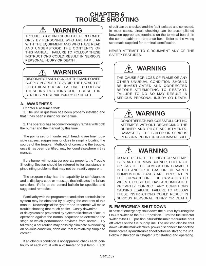
Sec1:37
CHAPTER 6TROUBLE SHOOTING
A. AWARENESS Chapter 6 assumes that: 1. The unit in question has been properly installed and that it has been running for some time. 2. The operator has become thoroughly familiar with both the burner and the manual by this time. The points set forth under each heading are brief, pos-sible causes, suggestions or clues to simplify locating the source of the trouble. Methods of correcting the trouble, once it has been identif ed, may be found elsewhere in this manual. If the burner will not start or operate properly, the Trouble Shooting Section should be referred to for assistance in pinpointing problems that may not be readily apparent. The program relay has the capability to self-diagnose and to display a code or message that indicates the failure condition. Refer to the control bulletin for speci f cs and suggested remedies. Familiarity with the programmer and other controls in the system may be obtained by studying the contents of this manual. Knowledge of the system and its controls will make trouble shooting that much easier. Costly downtimeor delays can be prevented by systematic checks of actual operation against the normal sequence to determine the stage at which performance deviates from normal. By following a set routine may possibly eliminate overlooking an obvious condition, often one that is relatively simple to correct.
If an obvious condition is not apparent, check each con-tinuity of each circuit with a voltmeter or test lamp. Each
circuit can be checked and the fault isolated and corrected. In most cases, circuit checking can be accomplished between appropriate terminals on the terminal boards in the control cabinet or entrance box. Refer to the wiring schematic supplied for terminal identif cation.
NEVER A TTEMPT TO CIRCUMVENT ANY OF THE SAFETY FEATURES.
B. EMERGENCY SHUT DOWNIn case of emergency, shut down the burner by turning the On-Off switch to the "OFF" position. Turn the fuel selector switch to the OFF position. Shut off the main manual fuel shut off valves on the fuel supply line. The unit can also be shut down with the main electrical power disconnect. Inspect the burner carefully and trouble shoot before re-starting the unit. Follow instruction in Chapter 3 for starting and operating.
THE CAUSE FOR LOSS OF FLAME OR ANY OTHER UNUSUAL CONDITION SHOULD BE INVESTIGA TED AND CORRECTED BEFORE A TTEMPTING TO RESTART. FAILURE TO DO SO MA Y RESUL T IN SERIOUS PERSONAL INJUR Y OR DEA TH.
WARNING
DO NOT REPEAT UNSUCCESSFUL LIGHTING ATTEMPTS WITHOUT RECHECKING THE BURNER AND PILOT ADJUSTMENTS. DAMAGE TO THE BOILER OR SERIOUS PERSONAL INJURY OR DEATH MAY RESULT.
WARNING
DO NOT RE-LIGHT THE PILOT OR ATTEMPT TO START THE MAIN BURNER, EITHER OIL OR GAS, IF THE COMBUSTION CHAMBER IS HOT AND/OR IF GAS OR OIL V APOR COMBUSTION GASES ARE PRESENT IN THE FURNACE OR FLUE P ASSAGES OR WHEN EXCESS OIL HAS ACCUMULATED. PROMPTLY CORRECT ANY CONDITIONS CAUSING LEAKAGE. F AILURE TO FOLLOW THESE INSTRUCTIONS COULD RESUL T IN SERIOUS PERSONAL INJUR Y OR DEA TH.
WARNING
DISCONNECT AND LOCK OUT THE MAIN POWER SUPPLY IN ORDER TO AVOID THE HAZARD OF ELECTRICAL SHOCK. F AILURE TO FOLLOW THESE INSTRUCTIONS COULD RESUL T IN SERIOUS PERSONAL INJURY OR DEATH.
WARNING
TROUBLE SHOOTING SHOULD BE PERFORMED ONLY BY PERSONNEL WHO ARE FAMILIAR WITH THE EQUIPMENT AND WHO HAVE READ AND UNDERST OOD THE CONTENTS OF THIS MANUAL. F AILURE TO FOLLOW THESE INSTRUCTIONS COULD RESUL T IN SERIOUS PERSONAL INJURY OR DEATH.
WARNING
Sec1:38
TROUBLE SHOOTING
PROBLEM SOLUTION
BURNER DOES NOT START 1. No voltage at program relay power input terminals. a. Main disconnect switch open. b. Blown control circuit fuse. c. Loose or broken electircal connection.
2. Program relay safety switch requires resetting
3. Limit circuit not completed - no voltage at end of limit circuit program relay terminal. a. Pressure or temperature is above setting of opeartion control. b. Water below required level. Low-water light (and alarm horn) should indicate this condition. Check manual reset button, if provided, on low-water control. c. Fuel pressure must be within settings of low pressure and high pressure switches. d. Check burner air proving switch and high f re limit switch. e. Heavy oil f red unit-oil temperature below minimum settings.
4. Fuel valve interlock circuit not completed. a. Fuel valve auxiliary switch not closed.
NO IGNITION 1. Lack of spark. a. Electrode grounded or porcelain cracked. b. Improper electrode setting. c. Loose terminal on ignition cable; cable shorted. d. Inoperative ignition transformer. e. Insuff cient or no voltage at pilot ignition circuit terminal.
2. Spark but no f ame. a. Lack of fuel - no gas pressure, closed valve, empty tank, broken line, etc.
3. Low f re switch open in low f re proving circuit. a. Damper motor not closed, slipped cam, defective switch. b. Damper jammed or linkage binding.
4. Running interlock circuit not completed. a. Combustion or atomizing air proving switches defective or not properly set. b. Motor starter interlock contact not closed.

Sec1:39
TROUBLE SHOOTING
PROBLEM SOLUTION
PILOT FLAME, BUT NO MAIN FLAME
1. Insuff cient pilot f ame.
2. Gas f red unit. a. Manual gas cock closed. b. Main gas valve inoperative. c. Gas pressure regulator inoperative. 3. Limit circuit not completed - no voltage at end of limit circuit program relay terminal. a. Oil supply cut off by obstruction, closed valve, or loss of suction. b. Supply pump inoperative. c. No fuel. d. Main oil valve inoperative. e. Check oil nozzle, gun and lines.
4. Flame detector defective, sight tube obstructed or lens dirty.
5. Insuff cient or no voltage at main fuel valve circuit terminal.
BURNER STAYS IN LOW FIRE 1. Pressure or temperature above modulating control setting.
2. Manual-automatic switch in wrong position.
3. Inoperative modulating motor.
4. Defective modulating control.
5. Binding or loose linkages, cams, setscrews, etc.
SHUTDOWN OCCURS DURING FIRING
1. Loss or stoppage of fuel supply.
2. Defective fuel valve; loose electrical connection.
3. Flame detector weak or defective.
4. Scanner lens dirty or sight tube obstructed.
5. If the programmer lockout swtich has not tripped, check the limit circuit for an opened safety control.

Sec1:40
TROUBLE SHOOTING
PROBLEM SOLUTION
SHUTDOWN OCCURS DURING FIRING (cont).
6. If the programmer lockout switch has tripped. a. Check fuel lines and valves. b. Check f ame detector. c. Check for open circuit in running interlock circuit. d. The f ame failure light is energized by ignition failure, main f ame failure, inadequate f ame signal, or open control in the running interlock circuit.
7. Improper air/fuel ratio (lean f re). a. Slipping linkage. b. Damper stuck open. c. Fluctuating fuel supply. Temporary obstruction in the fuel line. Temporary drop in gas pressure. Orif ce gate valve accidentally opened (heavy oil)
8. Interlock device inoperative or defective.
9. Air in the oil lines. Bleed lines.
MODULATING MOTOR DOES NOT OPERATE
1. Manual/automatic switch in wrong position.
2. Linkage loose or jammed.
3. Motor does not drive to open or close during pre-purge or close on burner shutdown. a. Motor defective. b. Loose electrical connection. c. Damper motor transformer defective.
4. Motor does not operate on demand. a. Manual/automatic switch in wrong position. b. Modulating control improperly set or inoperative. c. Motor defective d. Loose electrical connection. e. Damper motor transformer defective.

Sec1:41
A. LIMITED WARRANTY The Company warrants that at the time of shipment, the equipment manufactured by it shall be merchantable, free from defects in material and workmanship and shall possess the characteristics represented in writing by the Company. The Company's warranty is conditioned upon the equipment being properly installed and maintained and operated within the equipment's capacity under normal load conditions with competent supervised operators. Equipment, accessories and other parts and components not manufactured by the Company are warranted only to the extent of and by the original manufacture's warranty to the Company; In no event shall such other manufacturer's warranty create any more extensive warranty obligations of the Company to the Buyer than the Company's warranty covering equipment manufactured by the Company.
B. EXCLUSIONS FROM WARRANTY (I) THE FOREGOING IS IN LIEU OF ALL OTHER WARRANTIES, ORAL OR EXPRESS OR IMPLIED, INCLUDING ANY WARRANTIES THAT EXTEND BEYOND THE DESCRIPTION OF THE EQUIPMENT. THERE ARE NO EXPRESS WARRANTIES OTHER THAN THOSE CONTAINED HEREIN TO THE EXTENT PERMITTED BY THE LAW. THERE ARE NO IMPLIED WARRANTIES OF FITNESS FOR A PARTICULAR PURPOSE. THE PROVISIONS AS TO DURATION, WARRANTY ADJUSTMENT AND LIMITATION OF LIABILITY SHALL BE THE SAME FOR BOTH IMPLIED WARRANTIES (IF ANY) AND EXPRESSED WARRANTIES. (II) The Company's warranty is solely as stated in (a) above and does not apply or extend, for example, to: expendable item; ordinary wear and tear; altered units; units repaired by persons not expressly approved by the Company; materials not of the Company's manufacture; or damage caused by accident, the elements, abuse, misuse, temporary heat, overloading, or by erosive or corrosive substances or by the alien presence of oil, grease, scale, deposits or other contaminants in the equipment.
C. WARRANTY ADJUSTMENT Buyer must make claim of any breach of any warranty by written notice to the Company's home off ce within thirty (30) days of the discovery of any defect. The Company agrees at its option to repair or replace, BUT NOT INSTALL, F.O.B. Company's plant, any part or parts of the equipment which within twelve (12) months from the date of initial operation but no more than eighteen (18) months from date of shipment shall prove the Company's satisfaction (including return to the Company's plant, transportation prepaid, for inspection, if required by the Company) to be defective within the above warranty. Any warranty adjustments made by the Company shall not extend the initial warranty period set forth above. Expenses incurred by Buyer in replacing or repairing or returning the equipment or any part or parts will not be reimbursed by the Company.
D. SPARE AND REPLACEMENT PARTS WARRANTY ADJUSTMENT The Company sells spare and replacement parts. This subparagraph (d) is the warranty adjustment for such parts. Buyer must make claim of any breach of any spare or replacement parts by written notice to the Company's home off ce within thirty (30) days of the discovery of any alleged defect for all such parts manufactured by the company. The Company agrees at its option to repair or replace, BUT NOT INSTALL, F.O.B. Company's plant, any part or parts or material it manufacture which, within one (1) year from the date of shipment shall prove to Company's satisfaction (including return to the Company's plant, transportation prepaid, for inspection, if required by the Company) to be defective within this part warranty. The warranty and warranty period for spare and replacement parts not manufactured by the company (purchased by the Company, from third party suppliers) shall be limited to the warranty and warranty adjustment extended to the Company by the original manufacturer of such parts; In no event shall such other manufacturer's warranty create any more extensive warranty obligations of the Company to the Buyer for such parts than the Company's warranty adjustment covering part manufactured by the Company as set forth in this subparagraph (d). Expenses incurred by Buyer in replacing or repairing or returning the spare or replacement parts will not be reimbursed by the Company.
Warranty Policy

Sec1:42
E. LIMITATION OF LIABILITY The above warranty adjustment set forth Buyer's exclusive remedy and the extent of the Company's liability for breach of implied (if any) and express warranties, representations, instructions or defects from any cause in connection with the sale or use of the equipment. THE COMPANY SHALL NOT BE LIABLE FOR ANY SPECIAL, INDIRECT OR CONSEQUENTIAL DAMAGES OR FOR LOSS, DAMAGE OR EXPENSE, DIRECTLY OR INDIRECTLY ARISING FROM THE USE OF THE EQUIPMENT OR FROM ANY OTHER CAUSE WHETHER BASED ON WARRANTY (EXPRESS OR IMPLIED) OR TORT OR CONTRACT, and regardless of any advices or recommendations that may have been rendered concerning the purchase, installation, or use of the equipment.

Sec1:43
START-UP / SERVICE REPORTThe following information should be f lled in by the service technician at start-up or after any adjustment to the burner.
A copy of the start-up report MUST be returned to CB in order to validate the warranty of the burner.
Burner Model Serial Number Start-up Date
Test ConductedGAS OIL
Low 50% High Low 50% HighFiring Rate MMBtu / gph
Stack Temp (Gross) oF
Room Temp oF
O2%
CO2%
CO (PPM)
NOx (PPM)
Smoke (Bacharach)
Combustion Eff.%
Stack Draft "W.C.
Furnace Pressure "W.C.
Blast tube Pressure "W.C.
Steam Pressure PSIG
Water Temperature oF
Supply oil pressure PSIG
Return oil pressure PSIG
Vacuum oil pump "HG
Oil Temperature
Atom. air pressure
Gas Pressure @ Burner Inner Manifold
Manifold "W.C. Outer Manifold
Center Gas pressure "W.C.
Gas Pressure @ Regulator Inlet PSIG
Gas Pressure @ Regulator Outlet PSIG
Pilot Gas Pressure @ Regulator Outlet "W.C.
Flame Signal Main Low 50% High
Control Checks Test Set PointLow Water Cut OffAux. LWCOHigh Water Cut OffOperating LimitHigh LimitOperating ControlStack Temp InterlockFlame FailureCombustion Air SwitchHigh Purge SwitchLow Fire InterlockOil Pressure SwitchOil Valve with P.O.C.InterlockHigh Gas Pressure SwitchLow Gas Pressure SwitchGas Valve P.O.C. InterlockPilot Turndown TestFlame Signal Pilot
(For Low NOx Burners)Blast Tube Temp. InterlockFGR Line Purge SwitchFGR Valve P.O.C. Switch
Voltage AmperageElectric Motors L1 L2 L3 L1 L2 L3
Control VoltageBlower MotorAir CompressorAir-Oil or Metering
Adjusted by:
Date:
Accepted by:
(Signature Required)

Sec1:45
PRODUCT SATISFACTIONSURVEY
As a requirement of our ISO certif cation, please f ll-in this form and return to CB Prof re.Please rate your satisfaction with the following:
Delivery timeApperance of equipment after deliveryPiping and tubingWiringAll components arrived with equipmentEase of start-upPerformance of equipmentQuality of information provided Sales Engineering Service PartsOverall way any problems were handled
Burner Model Serial Number
Poor Good Excellent
Comments:
Date: By:

M/SERIESParts Manual

Sec2:1
M/SERIES PARTS SECTION
INSTRUCTIONS FOR THE USE OF THIS PART BOOKWHEN ORDERING REPAIR PARTS, PLEASE INCLUDE PART NUMBER, THE BURNER SERIAL NUMBER, MODEL, SIZE, AND VOLTAGE. THE INFORMATION CAN BE OBTAINED FROM THE BURNER NAMEPLATE AND THE VOLTAGE FROM THE DATA LABEL ON THE PANEL DOOR.
WHEN ORDERING FAN WHEELS, GIVE THE OVERALL DIAMETER, WIDTH, BORE, MANUFACTURER, AND MOTOR HP.
THIS PARTS BOOK DOES NOT INCLUDE SUCH COMMON HARDWARE ITEMS AS NUTS, WASHERS, ELEC-TRICAL PARTS, COPPER TUBING, FLARE FITTINGS, AND PIPE. ITEMS SUCH AS THESE CAN BE READILY PURCHASED LOCALLY.
THE FOLLOWING PARTS ARE SOLD ON EXCHANGE BASIS: OIL-AIR METERING PUMPS, OIL AND AIR PUMPS, BEARING ASSEMBLY, AIR MODULATORS, AND RELIEF VALVES.
PARTS SHIPPING POLICYALL ORDERS FOR STOCKED ITEMS WILL BE PROCESSED AND READY FOR SHIPMENT WITHIN (24) HOURS OF ITS RECEIPT.
AIR SHIPMENTS (U.P.S. OR OTHERWISE) WILL BE SHIPPED THE SAME DAY IF ORDER IS RECEIVED BE-FORE 2:30 P.M. (WEATHER PERMITTING).
GROUND SHIPMENTS TO WISCONSIN AND BORDERING STATES WILL BE SHIPPED THE SAME DAY UPON REQUEST.
ALL PARTS ORDERS AND EXHCNAGE PARTS MUST BE SENT TO:
CB Profi re351 -21st STREET
MONROE, WISCONSIN 53566
PLANT PHONE: (608) 325-3141FAX: (608) 325-4379
PARTS DIRECT: (608) 325-5003FAX: (608) 329-3190
Sec2:2
RETURN GOODS PROCEDURES (CREDIT OR REPLACEMENT PARTS)
Defective WARRANTY PARTS OR PARTS to be repaired are not to be returned to the PARTS DEPARTMENT without calling for a RETURN GOODS AUTHORIZATION NUMBER.
1) Before any item is RETURNED, PLEASE CALL THE PARTS DEPARTMENT TO OBTAIN AN RGA (RETURN GOODS AUTHORIZATION) NUMBER. PLEASE HAVE THE FOLLOWING INFORMATION AVAILABLE WHEN CALLING:
A) PART NUMBER OF ITEM B) DESCRIPTION OF ITEM C) REASON FOR THE RETURN WITH A FULL DESCRIPTION OF THE DEFECT(S) D) PARTS ORDER OR SALES ORDER ITEM WAS PURCHASED ON E) NAME, ADDRESS, AND DATE OF INSTALLATION F) DO YOU WANT CREDIT OR REPLACEMENT BEING ISSUED
2) Once an RGA number HAS BEEN ISSUED, THE ITEM MAY BE RETURNED. YOU WILL HAVE THIRTY (30) DAYS TO RETURN THE ITEM FROM THE DATE OF THE RGA BEING ISSUED OR THERE WILL BE A 10% HANDLING CHARGE.
3) RETURNED GOODS MUST HAVE THE RGA NUMBER APPEARING ON THE ADDRESS LABEL ATTACHED TO THE OUTSIDE OF THE BOX BEING RETURNED. IF THE RGA NUMBER IS NOT ON THE LABEL, YOUR CREDIT MAY BE DELAYED AND THERE WILL BE A $50.00 SERVICE CHARGE FOR PAPERWORK. ALL NEW PARTS RETURNED TO THE FACTORY WILL BE CHARGED WITH A 25% RESTOCKING FEE. PLEASE NOTE:FAILURE TO PROVIDE COMPLETE AND CORRECT INFORMATION MAY RESULT IN DELAYED OR CREDIT REFUSAL.
RETURN OF WARRANTY PARTS: WARRANTY PARTS MUST BE RETURNED TO THE FACTORY FREIGHT PREPAID, WITHIN THIRTY (30) DAYS AFTER A NEW PART HAS BEEN RECEIVED OR THERE WILL BE A 10% HANDLING CHARGE.
SHIPPING CHARGES: ON A WARRANTY PART, WE WILL ASSUME STANDARD SHIPPING CHARGES. THIS DOES NOT INCLUDE SPECIAL HANDLING SUCH AS AIR FREIGHT, U.P.S. NEXT DAY AIR SERVICE, OR U.P.S. SECOND DAY AIR SERVICE, ETC.
MOTOR WARRANTY POLICY:THE FOLLOWING PROCEDURE MUST BE USED FOR PROPER REPLACEMENT AND/OR REPAIR OF ELECTRIC MOTORS THAT HAVE FAILED UNDER WARRANTY.
1) Remove motor from unit and take motor to a MANUFACTURER AUTHORIZED SERVICE STATION.
2) The service station will determine the warranty status by INSTALLATION DATE OF THE UNIT, AND DATE OF FAILURE, along with the age of the motor, determined by the CODE DATE.
3) If the unit is within warranty, the unit will be inspected for cause of failure and repair requirements.
4) If the unit is within warranty limitations, the service station will repair on a "NO CHARGE" basis.
5) If the repairs are extensive, the service station will contact the motor manufacturer warranty manager to decide if the motor is to be repaired or replaced.
EXCEPTION TO THE ABOVE PROCEDURE:EMERGENCY SITUATIONS MAY DICTATE THAT BECAUSE OF THE DISTANCE BETWEEN USER AND AUTHORIZED SERVICE STATIONS, SEVERE DAMAGE OR INTERRUPTIONS MAY RESULT.
THE FOLLOWING PROCEDURE SHOULD BE USED: 1) SELECT A KNOWLEDGEABLE MOTOR REPAIR SHOP. 2) REPAIR SHOP TO CONTACT MOTOR MANUFACTURER WARRANTY REPAIR MANAGER, DETAILING REPAIRS NECESSARY ALONG WITH THE COMPLETE NAMEPLATE DATA BEFORE ANY REPAIRS ARE MADE.
3) IF ANY PROBLEMS OCCUR, THE CB PROFIRE PARTS DEPT. WILL PROVIDE ASSISTANCE.

Sec2:3
FAILURE TO FOLLOW THE NEXT PROCEDURE WILL RESULT INREPAIRS BEING MADE AT THE CUSTOMERS EXPENSE.
*MARATHON ELECTRIC - ELECTRIC MOTORS WARRANTY REPAIR PROCEDURE
THE FOLLOWING PROCEDURE MUST BE USED FOR PROPER REPLACEMENT AND/R REPAIR OF MARATHON ELECTRIC MOTORS THAT HAVE FAILED UNDER WARRANTY.
1) END USER WILL REMOVE MOTOR FROM UNIT AND TAKE FAILED MOTOR TO MARATHON ELECTRIC AUTHORIZED SERVICE STATION.
2) SERVICE STATION WILL DETERMINE WARRANTY STATUS BY INSTALLATION DATE OF UNIT AND DATE OF FAILURE ALONG WITH AGE OF MOTOR DETERMINED BY DATE CODE.
3) IF WINTHIN WARRANTY LIMITATIONS, UNIT WILL BE INSPECTED FOR CAUSE OF FAILURE AND REPAIR REQUIREMENTS. DETERMINATION WILL BE MADE THAT FAILURE WAS CAUSED BY DEFECT IN MATERIALS OR WORKMANSHIP AND NOT BY MISUSE, ABUSE, ACCIDENT, OR OTHER EXCLUSIONS LISTED IN OUR WARRANTY.
4) IF MINOR REPAIR IS REUIRED, SERVICE STATION WILL REPAIR MOTOR AND RETURN TO USER ON A "NO CHARGE" BASIS.
5) IF MAJOR REPAIR (REWIND) IS REQUIRED, SERVICE STATION MAY:
A) REWIND MOTOR AND RETURN TO USER ON A "NO CHARGE" BASIS IF USER REQUIREMENT IS NOT AN EMERGENCY AND REPAIR CAN BE MADE WITHIN MARATHON ELECTRIC PRICE GUIDELINES, OR
B) NAMEPLATE WILL BE REMOVED AND ALONG WITH A REPORT OF CAUSE OF FAILURE WILL BE GIVEN TO THE USER.
6) USER WILL PRESENT NAMEPLATE AND REPORT TO DISTRIBUTOR.
7) DISTRIBUTOR WILL FURNISH USER WITH A NEW MOTOR, NO CHARGE, EITHER FROM INVENTORY OR SECURE REPLACEMENT UNIT DIRECT FROM PARENT ORGANIZTION.
*MARATHON ELECTRICWARRANTY REPAIR PROCEDURE, DPN-79-113
ELECTRIC MOTORS, 48-215 FRAME

Sec2:4
AIR CLEANER ..................................................................................................... AIR MODULATION ............................................................................................... BLAST TUBES ...................................................................................................... CAM TRIM ............................................................................................................COILS, COOLING ................................................................................................. COMPRESSORS, AIR .......................................................................................... CONTROLS, ELECTRICAL .................................................................................. DIFFUSERS .......................................................................................................... DAMPER, LOUVER-TYPE ....................................................................................DRAWER ASSEMBLIES .......................................................................................DRY OVENS ......................................................................................................... ELECTRODES, IGNITION .................................................................................... FILTERS, AIR (REPLACEMENT) ..........................................................................FILTERS, OIL ........................................................................................................GAUGES, PRESSURE .........................................................................................HEATERS, OIL ......................................................................................................HOUSING, FAN ....................................................................................................IMPELLERS, AIR ..................................................................................................MODULES, SEPARATE COMPRESSOR .............................................................MOTORS, ELECTRIC - BLOWER ........................................................................ - COMPRESSOR ..................................................................................... - MODULATING ....................................................................................... - OIL PUMP ..............................................................................................NOZZLES, OIL ......................................................................................................PILOTS, GAS ........................................................................................................PUMPS, OIL METERING ......................................................................................REGULATOR, GAS ...............................................................................................SCANNER .............................................................................................................SHEAVES ..............................................................................................................STARTERS, MOTOR ............................................................................................STRAINERS, OIL ..................................................................................................SWITCHES, AIR ....................................................................................................SWITCHES, CONTROL ........................................................................................SWITCHES, GAS ..................................................................................................TRANSFORMERS ................................................................................................TANKS, AIR-OIL ....................................................................................................VALVES, AIR .........................................................................................................VALVES, GAS .......................................................................................................VALVES, OIL .........................................................................................................V-BELTS ................................................................................................................
5, 7, 8101111, 7, 87, 8122, 312, 312, 35, 7, 87, 85, 7, 85, 6117, 817, 810, 114, 5, 62, 32, 3592, 38127, 81, 1212915, 7, 87, 894, 5, 68
TABLE OF CONTENTS SECTION 2:0
ITEM FIG. NO.

Sec2:5
FIGURE 1. BLOWER HOUSING & BLAST TUBE ASSEMBLIES

Sec2:6
BLOWER HOUSING & BLAST TUBE ASSEMBLIES QUANTITYITEM NO. PART NO. DESCRIPTION 14 22 28 30 34 42 54 63 84 105
1 279-121 DRY OVEN 1 1
279-120 DRY OVEN 1 1
279-58 DRY OVEN 1 1 1 1
279-60 DRY OVEN 1 1
2 32-1072 GASKET, DRY OVEN 1 1
32-1062 GASKET, DRY OVEN 1 1
32-1020 GASKET, DRY OVEN 1 1 1 1
32-1021 GASKET, DRY OVEN 1 1
3 40-332 HOUSING, BLAST TUBE 1 1
40-331 HOUSING, BLAST TUBE 1 1
40-327 HOUSING, BLAST TUBE 1 1 1 1
40-279 HOUSING, BLAST TUBE 1 1
4 832-118 IGNITION TRANSFORMER, 10,000 VOLT, DIRECT SPARK 1 1 1 1 1 1 1 1 1 1
832-107 IGNITION TRANSFORMER, 6,000 VOLT, GAS PILOT 1 1 1 1 1 1 1 1 1 1
5 836-366 SWITCH, AIR PRESSURE 1 1 1 1 1 1 1 1 1 1
6 56-281 PIN, HINGE 1 1 1 1 1 1 1 1
56-284 PIN, HINGE 1 1
7 8--1242 BRACKET, COOLING COIL CONNECTION ME, MEG ONLY 1 1 1 1 1 1
8 31-38 GLASS, FLAME SIGHT 1 1 1 1 1 1 1 1 1 1
9 8-1203 BRACKET, SIGHT GLASS RETAINER 2 2 2 2 2 2 2 2 2 2
10 SEE CHART MOTOR, BLOWER 1 1 1 1 1 1 1 1 1 1
11 17-124 COIL, COOLING 1 1 1 1
12 80-183 RING, AIR DEFLECTION (3 PHASE) 1 1
80-191 RING, AIR DEFLECTION (1 PHASE) 1 1
8-178 RING, AIR DEFLECTION 1 1 1 1
13 32-1060 GASKET, FAN HOUSING SEAL, 5 FT. 1 1 1 1 1 1 1 1
32-1060 GASKET, FAN HOUSING SEAL, 7 FT. 1 1
14 85-877 FAN HOUSING 1 1
85-876 FAN HOUSING 1 1
85-874 FAN HOUSING 1 1 1 1
85-875 FAN HOUSING (63-P) 1
40-280 FAN HOUSING 1 1
15 19-430 COVER, COIL INLET, ME, MEG 1 1 1 1 1 1
19-429 COVER 1 1 1 1 1 1
16 77-207 SPACER, IMPELLER (QUANTITY VARIES)
77-197 SPACER, IMPELLER (QUANTITY VARIES)
17 SEE CHART IMPELLER 1 1 1 1 1 1 1 1 1 1
18 22-300 PLATE, AIR INLET 1 1
22-295 PLATE, AIR INLET 1 1
22-192 PLATE, AIR INLET 1 1 1 1
22-217 PLATE, AIR INLET 1 1
19 265-31 CONE, AIR INLET 1 1 1 1 1 1 1 1
265-34 CONE, AIR INLET (84S) 1
265-36 CONE, AIR INLET (84P) 1 1
20 82-750 SPRING 2 2 2 2 2 2 2 2 3 3
21 427-72 DAMPER, AIR ASSEMBLY WITH AIR MODULATION 1 1
427-71 DAMPER, AIR ASSEMBLY 1 1 1 1
427-64 DAMPER, AIR ASSEMBLY 1 1 1 1
427-48 DAMPER, AIR ASSEMBLY 1 1
22 8-1359 BRACKET, REAR COVER MOUNTING 1 1 1 1
8-1213 BRACKET, REAR COVER MOUNTING 1 1 1 1
23 19-463 COVER, DAMPER INLET WITH AIR MODULATION 1 1
19-450 COVER, DAMPER INLET 1 1
19-447 COVER, DAMPER INLET 1 1
19-427 COVER, DAMPER INLET 1 1 1 1
461-89 COVER, DAMPER INLET 1 1

Sec2:7
FIGURE 2. DRAWER ASSEMBLY, M14-63
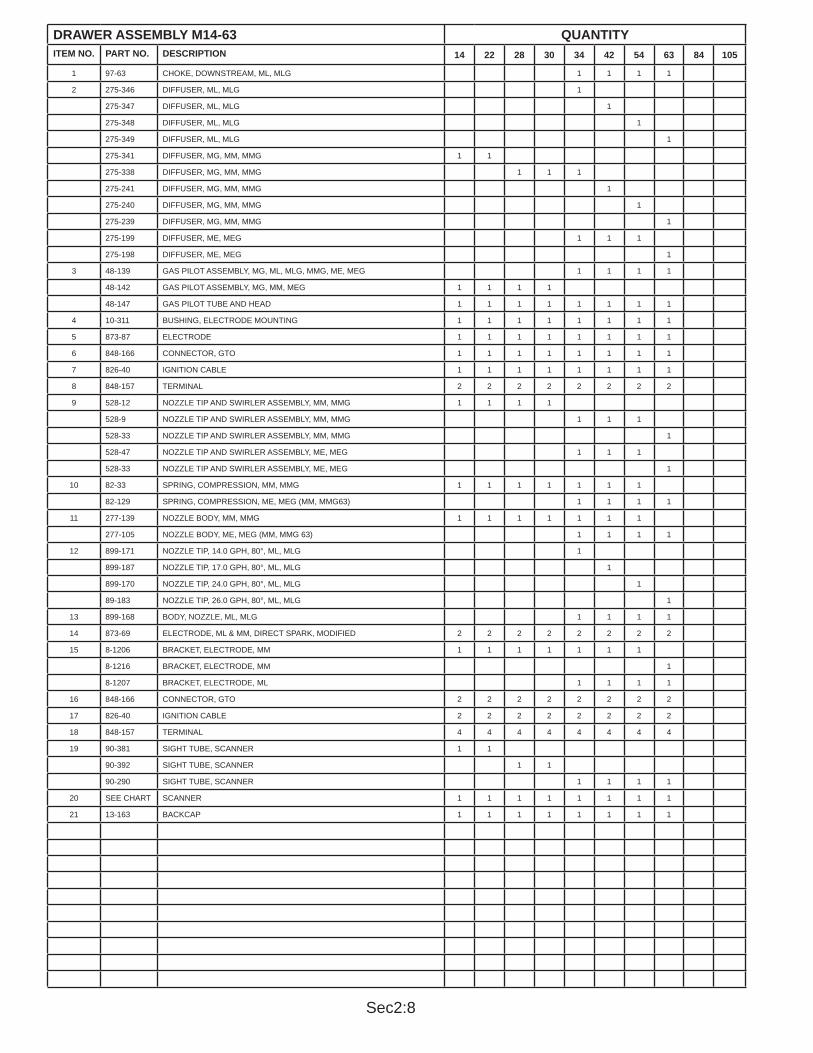
Sec2:8
DRAWER ASSEMBLY M14-63 QUANTITYITEM NO. PART NO. DESCRIPTION 14 22 28 30 34 42 54 63 84 105
1 97-63 CHOKE, DOWNSTREAM, ML, MLG 1 1 1 1
2 275-346 DIFFUSER, ML, MLG 1
275-347 DIFFUSER, ML, MLG 1
275-348 DIFFUSER, ML, MLG 1
275-349 DIFFUSER, ML, MLG 1
275-341 DIFFUSER, MG, MM, MMG 1 1
275-338 DIFFUSER, MG, MM, MMG 1 1 1
275-241 DIFFUSER, MG, MM, MMG 1
275-240 DIFFUSER, MG, MM, MMG 1
275-239 DIFFUSER, MG, MM, MMG 1
275-199 DIFFUSER, ME, MEG 1 1 1
275-198 DIFFUSER, ME, MEG 1
3 48-139 GAS PILOT ASSEMBLY, MG, ML, MLG, MMG, ME, MEG 1 1 1 1
48-142 GAS PILOT ASSEMBLY, MG, MM, MEG 1 1 1 1
48-147 GAS PILOT TUBE AND HEAD 1 1 1 1 1 1 1 1
4 10-311 BUSHING, ELECTRODE MOUNTING 1 1 1 1 1 1 1 1
5 873-87 ELECTRODE 1 1 1 1 1 1 1 1
6 848-166 CONNECTOR, GTO 1 1 1 1 1 1 1 1
7 826-40 IGNITION CABLE 1 1 1 1 1 1 1 1
8 848-157 TERMINAL 2 2 2 2 2 2 2 2
9 528-12 NOZZLE TIP AND SWIRLER ASSEMBLY, MM, MMG 1 1 1 1
528-9 NOZZLE TIP AND SWIRLER ASSEMBLY, MM, MMG 1 1 1
528-33 NOZZLE TIP AND SWIRLER ASSEMBLY, MM, MMG 1
528-47 NOZZLE TIP AND SWIRLER ASSEMBLY, ME, MEG 1 1 1
528-33 NOZZLE TIP AND SWIRLER ASSEMBLY, ME, MEG 1
10 82-33 SPRING, COMPRESSION, MM, MMG 1 1 1 1 1 1 1
82-129 SPRING, COMPRESSION, ME, MEG (MM, MMG63) 1 1 1 1
11 277-139 NOZZLE BODY, MM, MMG 1 1 1 1 1 1 1
277-105 NOZZLE BODY, ME, MEG (MM, MMG 63) 1 1 1 1
12 899-171 NOZZLE TIP, 14.0 GPH, 80°, ML, MLG 1
899-187 NOZZLE TIP, 17.0 GPH, 80°, ML, MLG 1
899-170 NOZZLE TIP, 24.0 GPH, 80°, ML, MLG 1
89-183 NOZZLE TIP, 26.0 GPH, 80°, ML, MLG 1
13 899-168 BODY, NOZZLE, ML, MLG 1 1 1 1
14 873-69 ELECTRODE, ML & MM, DIRECT SPARK, MODIFIED 2 2 2 2 2 2 2 2
15 8-1206 BRACKET, ELECTRODE, MM 1 1 1 1 1 1 1
8-1216 BRACKET, ELECTRODE, MM 1
8-1207 BRACKET, ELECTRODE, ML 1 1 1 1
16 848-166 CONNECTOR, GTO 2 2 2 2 2 2 2 2
17 826-40 IGNITION CABLE 2 2 2 2 2 2 2 2
18 848-157 TERMINAL 4 4 4 4 4 4 4 4
19 90-381 SIGHT TUBE, SCANNER 1 1
90-392 SIGHT TUBE, SCANNER 1 1
90-290 SIGHT TUBE, SCANNER 1 1 1 1
20 SEE CHART SCANNER 1 1 1 1 1 1 1 1
21 13-163 BACKCAP 1 1 1 1 1 1 1 1

Sec2:9
FIGURE 3. DRAWER ASSEMBLY, M84-105
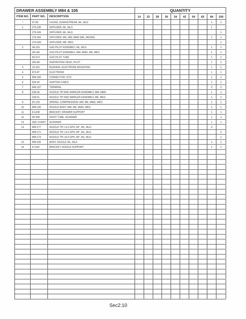
Sec2:10
DRAWER ASSEMBLY M84 & 105 QUANTITYITEM NO. PART NO. DESCRIPTION 14 22 28 30 34 42 54 63 84 105
* 97-65 CHOKE, DOWNSTREAM, ML, MLG 1 1
1 275-235 DIFFUSER, ML, MLG 1
275-226 DIFFUSER, ML, MLG 1
275-264 DIFFUSER, MG, MM, MMG (ME, MEG84) 1 1
275-269 DIFFUSER, ME, MEG 1
2 48-153 GAS PILOT ASSEMBLY, ML, MLG 1 1
48-140 GAS PILOT ASSEMBLY, MM, MMG, ME, MEG 1 1
90-374 GAS PILOT TUBE 1 1
284-68 INSPIRATING HEAD, PILOT 1 1
3 10-310 BUSHING, ELECTRODE MOUNTING 1 1
4 873-87 ELECTRODE 1 1
5 848-166 CONNECTOR, GTO 1 1
6 826-40 IGNITION CABLE 1 1
7 848-157 TERMINAL 2 2
8 528-36 NOZZLE TIP AND SWIRLER ASSEMBLY, MM, MMG 1 1
528-31 NOZZLE TIP AND SWIRLER ASSEMBLY, ME, MEG 1 1
9 82-129 SPRING, COMPRESSION, MM, ME, MMG, MEG 1 1
10 899-105 NOZZLE BODY, MM, ME, MMG, MEG 1 1
11 8-1248 BRACKET, DRAWER SUPPORT 1 1
12 90-338 SIGHT TUBE, SCANNER 1 1
13 SEE CHART SCANNER 1 1
14 899-177 NOZZLE TIP, 12.0 GPH, 80°, ML, MLG 3
899-171 NOZZLE TIP, 14.0 GPH, 80°, ML, MLG 2
899-173 NOZZLE TIP, 16.0 GPH, 80°, ML, MLG 1
15 899-200 BODY, NOZZLE ML, MLG 1 1
16 8-1042 BRACKET, NOZZLE SUPPORT 1 1

Sec2:11
FIGURE 4. OIL PIPING ASSEMBLY, PRESSURE ATOMIZING - ML
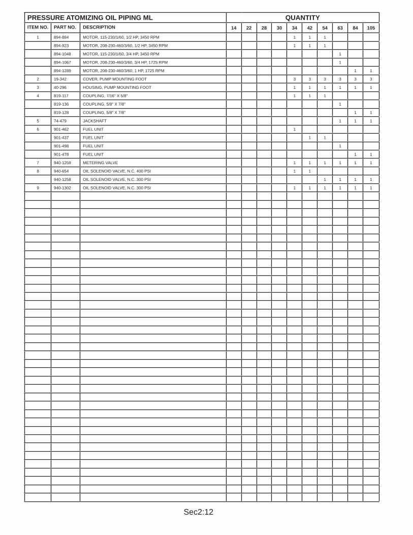
Sec2:12
PRESSURE ATOMIZING OIL PIPING ML QUANTITYITEM NO. PART NO. DESCRIPTION 14 22 28 30 34 42 54 63 84 105
1 894-884 MOTOR, 115-230/1/60, 1/2 HP, 3450 RPM 1 1 1
894-923 MOTOR, 208-230-460/3/60, 1/2 HP, 3450 RPM 1 1 1
894-1048 MOTOR, 115-230/1/60, 3/4 HP, 3450 RPM 1
894-1067 MOTOR, 208-230-460/3/60, 3/4 HP, 1725 RPM 1
894-1289 MOTOR, 208-230-460/3/60, 1 HP, 1725 RPM 1 1
2 19-342 COVER, PUMP MOUNTING FOOT 3 3 3 3 3 3
3 40-296 HOUSING, PUMP MOUNTING FOOT 1 1 1 1 1 1
4 819-117 COUPLING, 7/16" X 5/8" 1 1 1
819-136 COUPLING, 5/8" X 7/8" 1
819-128 COUPLING, 5/8" X 7/8" 1 1
5 74-479 JACKSHAFT 1 1 1
6 901-462 FUEL UNIT 1
901-437 FUEL UNIT 1 1
901-498 FUEL UNIT 1
901-478 FUEL UNIT 1 1
7 940-1259 METERING VALVE 1 1 1 1 1 1
8 940-654 OIL SOLENOID VALVE, N.C. 400 PSI 1 1
940-1258 OIL SOLENOID VALVE, N.C. 300 PSI 1 1 1 1
9 940-1302 OIL SOLENOID VALVE, N.C. 300 PSI 1 1 1 1 1 1

Sec2:13
FIGURE 5. AIR ATOMIZING OIL METERING ASSEMBLY MM, ME

Sec2:14
AIR ATOMIZING OIL METERING ASSEMBLY MM, ME QUANTITYITEM NO. PART NO. DESCRIPTION 14 22 28 30 34 42 54 63 84 105
1 894-935 MOTOR, 3/4 HP, 115-230/1/60 1 1 1 1
894-936 MOTOR, 3/4 HP, 208-230-460/3/60 1 1 1 1
894-1292 MOTOR, 1 HP, 115-230/1/60 1 1 1
894-1289 MOTOR, 1 HP, 208-230-460/3/60 1 1 1
894-1294 MOTOR, 2 HP, 115-230/1/60 1
894-1295 MOTOR, 2 HP, 208-230-460/3/60 1 1 1
2 19-342 COVER, PUMP MOUNTING HOUSING 3 3 3 3 3 3 3 3 3 3
3 40-243 HOUSING, PUMP MOUNTING 1 1 1 1 1 1 1 1 1 1
4 819-114 COUPLING, 5/8" X 9/16" 1 1 1 1 1 1 1 1 1
819-127 COUPLING, 5/8" X 9/16" 1
5 695-104 PUMP, AIR/OIL, NO. 3-4 1
695-88 PUMP, AIR/OIL, NO. 4-4 1
695-90 PUMP, AIR/OIL, NO. 5-4 1 1 1 1
695-92 PUMP, AIR/OIL, NO. 6-4 1
695-111 PUMP, AIR/OIL, NO. 7-7S 1
695-98 PUMP, AIR/OIL, NO. 8-7S 1 1
6 195-257 TANK, AIR/OIL 1 1
195-256 TANK, AIR/OIL 1 1 1 1 1 1 1 1
195-246 TANK, AIR/OIL 1 1
7 851-176 SIGHT GLASS, OIL LEVEL 1 1 1 1 1 1 1 1 1 1
8 850-3 GAUGE, PRESSURE, 0-60#, 2 1/2" DIAL 1 1 1 1 1 1 1 1 1 1
9 941-187 VALVE, NEEDLE, AIR SHUTOFF 1/8" X 1/4" 1 1 1 1 1 1 1 1 1 1
10 923-115 CLEANER, AIR WITH FILTER 1 1 1 1 1 1 1 1 1 1
843-114 FILTER, AIR (REPLACEMENT) 1 1 1 1 1 1 1 1 1 1
11 940-1200 VALVE, CHECK, HORIZONTAL, 125 PSI W.O.G. 1/4" 1 1 1 1 1 1 1 1
940-1169 VALVE, CHECK, HORIZONTAL, 125 PSI W.O.G. 1/2" 1 1
* 940-1205 VALVE, CHECK, HORIZONTAL, 125 PSI W.O.G. 3/4" 1 1
12 257-74 MANIFOLD, 14 1/2" LONG, (2 KW) 1 1
257-70 MANIFOLD, 21 1/2" LONG, (3 & 5 KW) 1 1 1 1 1 1 1 1
13 32-1000 GASKET 1 1 1 1 1 1 1 1 1 1
14 832-395 HEATER, 2 KW, 230/1/60 W/C.O.L. 1 1
832-394 HEATER, 2 KW, 115/1/60 W/C.O.L. 1 1
832-691 HEATER, 3 KW, 230/1/60 W/C.O.L. 1 1 1 1 1 1
832-692 HEATER, 5 KW, 230/1/60 W/C.O.L. 1 1
15 937-163 GAUGE, TEMPERATURE, 50-300° 1 1 1 1 1 1 1 1 1 1
16 940-1270 VALVE, OIL, 3 WAY, 3/8" 1 1 1 1 1 1 1 1 1
940-1271 VALVE, OIL, 3 WAY, 1/2" 1

Sec2:15
FIGURE 6. OIL PIPING ASSEMBLY, AIR ATOMIZING - ME34-105

Sec2:16
OIL PIPING ASSEMBLY ME34-105 QUANTITYITEM NO. PART NO. DESCRIPTION 14 22 28 30 34 42 54 63 84 105
1 894-933 MOTOR, 115-230/1/60, 1/2 HP, 1725 RPM 1 1 1 1 1 1
2 40-243 HOUSING, PUMP MOUNTING 1 1 1 1 1 1
3 19-342 COVER, PUMP MOUNTING HOUSING 3 3 3 3 3 3
4 819-105 COUPLING, 5/8" X 5/8" 1 1 1 1 1 1
5 695-80 METERING HEAD, #30 1 1
695-70 METERING HEAD, #40 1 1
695-71 METERING HEAD, #60 1
695-81 METERING HEAD, #75 1
6 282-13 OVER RIDE STOP 1 1 1 1 1 1
7 476-54 ARM, ASSEMBLY 1 1 1 1 1 1
8 882-14 ARM, ACTUATING, (SMALLER) 1 1 1 1 1 1
9 2-134 ARM, STRAIN RELEASE 2 2 2 2 2 2
10 924-50 SPRING, STRAIN RELEASE 1 1 1 1 1 1
11 882-27 ARM, ACTUATING (LARGER) 1 1 1 1 1 1
12 10-254 BUSHING, METER PUMP 1 1 1 1 1 1
13 824-6 COLLAR 1 1 1 1 1 1
14 940-1271 VALVE, OIL, 3 WAY, 1/2" 1 1 1 1 1 1
15 937-163 GAUGE, TEMPERATURE, 50°-300° 1 1 1 1 1 1
16 257-70 MANIFOLD, 21 1/2" LONG 1 1 1 1 1 1
17 32-1000 GASKET 1 1 1 1 1 1
18 832-691 HEATER, 3 KW, 230/1/60 1 1 1 1
832-692 HEATER, 5 KW, 230/1/60 1 1

Sec2:17
FIGURE 7. SEPARATE COMPRESSOR MODULE, ME 34-54

Sec2:18
SEPARATE COMPRESSOR MODULE, ME34-54 QUANTITYITEM NO. PART NO. DESCRIPTION 14 22 28 30 34 42 54 63 84 105
732-102 SEPARATE COMPRESSOR ASSEMBLY 1 1 1
1 195-246 TANK, AIR/OIL 1 1 1
2 851-176 SIGHTGLASS, OIL LEVEL 1 1 1
3 850-3 GAUGE, PRESSURE, 0-60# 1 1 1
4 940-1205 VALVE, CHECK, 3/4" 2 2 2
5 843-97 FILTER, MESH, 2" X 12" 1 1 1
6 13-167 CAP, STRAINER 1 1 1
7 3-281 BASE 1 1 1
8 843-106 FILTER, FULL FLOW 1 1 1
9 505-205 COMPRESSOR, AIR #7 1 1 1
10 819-105 COUPLING, FLEXIBLE 5/8" X 5/8" 1 1 1
11 40-243 HOUSING, PUMP MOUNTING 1 1 1
12 19-342 COVER, PUMP MOUNTING COVER 3 3 3
13 894-1295 MOTOR, ELECTRIC, 2 HP, 208-230-460/3/60, 1725 RPM 1 1 1
14 941-585 COCK , SHUTOFF 1 1 1
15 923-115 CLEANER, AIR WITH FILTER 1 1 1
843-114 FILTER, AIR (REPLACEMENT) 1 1 1
16 8-1292 BRACKET, SUPPORT, COOLING COIL 1 1 1
17 8-1252 BRACKET, SUPPORT, COOLING COIL 1 1 1
18 848-416 BOX, JUNCTION, 4" X 5" 1 1 1
* 832-653 TERMINAL BLOCK, 1 PAIR 6 6 6
* 832-654 TERMINAL BLOCK, END 1 1 1
19 17-133 COOLING COIL ASSEMBLY (INCLUDES GUARDS, FAN, COIL) 1 1 1
35-320 GUARD, COOLING COIL COVER AND MOTOR MOUNT 1 1 1
35-321 GUARD, COOLING COIL 1 1 1
20 951-144 FAN, COOLING COIL 115/1/60, 3100 RPM 1 1 1
21 17-134 COIL, COOLING 1 1 1
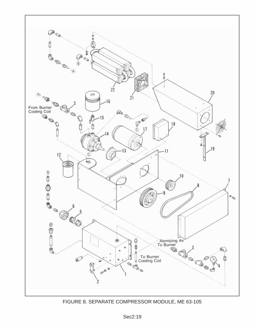
Sec2:19
FIGURE 8. SEPARATE COMPRESSOR MODULE, ME 63-105

Sec2:20
SEPARATE COMPRESSOR MODULE ME63-105 QUANTITYITEM NO. PART NO. DESCRIPTION 14 22 28 30 34 42 54 63 84 105
732-104 SEPARATE COMPRESSOR ASSEMBLY ME-MEG 63, 84 & 105
1 732-101 TANK, AIR/OIL ASSEMBLY 1 1 1
195-246 TANK, AIR/OIL 1 1 1
2 851-176 SIGHTGLASS, OIL LEVEL 1 1 1
3 940-1205 VALVE, CHECK, 3/4" 2 2 2
4 850-3 GAUGE, PRESSURE, 2 1/2" DIAL, 0-60# 1 1 1
5 843-97 FILTER, MESH, 2" X 12" 1 1 1
6 13-167 CAP, STRAINER 1 1 1
7 35-290 GUARD, BELT 1 1 1
8 809-212 BELT, V 2 2 2
9 921-485 SHEAVE, COMPRESSOR 1 1 1
10 921-505 SHEAVE, MOTOR 1 1 1
11 3-273 BASE 1 1 1
12 843-106 FILTER, FULL FLOW 1 1 1
13 29-841 FLANGE, MOUNTING, COMPRESSOR 1 1 1
14 505-169 COMPRESSOR, AIR, 2" 1 1 1
15 941-562 COCK, SHUTOFF, 3/4" 1 1 1
16 923-112 CLEANER, AIR WITH FILTER 1 1 1
843-112 FILTER, AIR (REPLACEMENT) 1 1 1
17 894-1291 MOTOR, 3 HP, 3450 RPM 1 1 1
18 848-416 BOX, JUNCTION 4" X 5", WITH TERMINAL BLOCK 1 1 1
19 8-1251 BRACKET, COOLING COIL SUPPORT 1 1 1
20 17-133 COOLING COIL ASSEMBLY (INCLUDES GUARDS, FAN & COIL) 1 1 1
35-321 GUARD, COOLING COIL 1 1 1
35-320 GUARD, COOLING COIL COVER AND MOTOR MOUNT 1 1 1
21 951-144 FAN, COOLING COIL, 115/1/60, 3100 RPM 1 1 1
22 17-134 COIL, COOLING 1 1 1

Sec2:21
FIGURE 9. MAIN & PILOT GAS TRAINS

Sec2:22
MAIN & GAS PILOT TRAINS QUANTITYITEM NO. PART NO. DESCRIPTION 14 22 28 30 34 42 54 63 84 105
MAIN GAS TRAIN
1 940-1129 VALVE, BUTTERFLY, 1" 1
940-1254 VALVE, BUTTERFLY, 1 1/2" 1
940-1192 VALVE, BUTTERFLY, 2" FULL PORT 1 1 1 1 1 1
940-1230 VALVE, BUTTERFLY, 2 1/2" FULL PORT 1 1
2 941-594 SHUTOFF COCK, 1" 2
941-127 SHUTOFF COCK, 1 1/2" 2
941-128 SHUTOFF COCK, 2" 2 2 2 2
941-129 SHUTOFF COCK, 2 1/2", LUBRICATED 2 2
941-130 SHUTOFF COCK, 3", LUBRICATED 2 2
3 940-1103 VALVE, GAS DIAPHRAGM, 1" 1
940-1090 VALVE, GAS DIAPHRAGM, 1 1/2" 1
4 817-571 SWITCH, GAS PRESSURE, HIGH 1 1 1 1 1 1 1 1
5 940-1221 VALVE, BODY, 2" 1 1 1 1
940-1203 VALVE, BODY 2 1/2" P.O.C. 1 1
940-1222 VALVE, BODY, 3" 1 1
6 945-122 ACTUATOR, 13 SEC. 1 1 1 1 1 1 1 1
7 940-1173 VALVE, SOLENOID, K3E, 2 1/2" 1 1
940-1098 VALVE, SOLENOID, K3E, 3" 1 1
8 817-570 SWITCH, GAS PRESSURE, LOW 1 1 1 1 1 1 1 1
9 817-582 REGULATOR, GAS PRESSURE, 1" RV 60 1
817-622 REGULATOR, GAS PRESSURE, 1 1/2" 1
817-617 REGULATOR, GAS PRESSURE, 2" RV 91 1 1 1 1
817-634 REGULATOR, GAS PRESSURE, 2 1/2" RV 110 1 1
817-588 REGULATOR, GAS PRESSURE, 3" RV 110 1 1
PILOT GAS TRAIN
1 825-137 SHUTOFF COCK, 1/2" 1 1 1 1 1 1 1 1 1 1
2 817-695 REGULATOR, GAS PRESSURE, 1/2" 1 1 1 1
817-580 REGULATOR, GAS PRESSURE, 1/2" RV52 1 1 1 1 1 1
3 940-1127 VALVE, GAS PILOT, 1/2" 1 1 1 1 1 1 1 1 1 1

Sec2:23
FIGURE 10. AIR & ELECTRIC MODULATION, LINKAGE

Sec2:24
AIR & ELECTRIC MODULATION, LINKAGE QUANTITYITEM NO. PART NO. DESCRIPTION 14 22 28 30 34 42 54 63 84 105
AIR MODULATION MM 14-63
1 940-1213 VALVE, SOLENOID, N.O. 325 PSI 1 1 1 1 1 1 1 1
2 8-1383 BRACKET, AIR MODULATOR 1 1 1 1
8-1184 BRACKET, AIR MODULATOR 1 1 1 1
3 2-147 ARM, AIR MODULATOR 1 1 1 1
4 269-1 AIR MODULATOR 1 1 1 1 1 1 1 1
5 2-111 ARM, ACTUATING 2 2 2 2 2 2 2 2
6 883-35 BALL JOINT, 5/16" - 24 DISCONNECT 1 1 1 1 1 1 1 1
7 970-1 THREADED ROD, 5/16" - 24 (SPECIFY LENGTH) 1 1 1 1 1 1 1 1
8 883-8 BALL JOINT, 5/16" X STRAIGHT 2 2 2 2 2 2 2 2
9 67-123 ROD, BRASS, 1/4" X 12" LONG, T.O.E. 1 1 1 1 1 1 1 1
10 883-11 BALL JOINT, 1/4" X 90° 1 1 1 1 1 1 1 1
ELECTRIC MODULATION ML, MLG 34-105 MM, MMG 14-30
1 883-008 BALL JOINT, 5/16" X STRAIGHT 3 3 3 3 3 3 3 3 3 3
2 2-30 ARM, ACTUATING 1 1 1 1 1 1 1 1 1 1
3 807-335 BEARING 1 1 1 1 1 1 1 1 1 1
4 18--111 COLLAR 1 1 1 1 1 1 1 1 1 1
5 2-14 ARM, ACTUATING, SLOTTED 2 2 2 2 2 2 2 2 2 2
6 10-308 BUSHING, 15 1/4" LG 1 1
10-314 BUSHING, 18 1/2" LG 1 1 1 1 1 1
10-307 BUSHING, 28" LG 1 1
7 894-1288 MODULATION MOTOR, 90° (MG84) 1 1 1 1 1 1 1 1
894-1305 MODULATION MOTOR, 90° 1 1
8 970-1 THREADED ROD, 5/16" - 24 (SPECIFY LENGTH) 1 1 1 1 1 1 1 1 1 1
9 2-112 ARM, ACTUATING 1 1 1 1 1 1 1 1 1 1
10 883-35 BALL JOINT 5/16" - 24 DISCONNECT 1 1 1 1 1 1 1 1 1 1
11 977-6 ROD, BRASS, 1/4" DIA. (SPECIFY LENGTH) 1 1 1 1 1 1 1 1 1 1
12 883-11 BALL JOINT, 1/4" X 90° 2 2 2 2 2 2 2 2 2 2
13 2-103 ARM, ACTUATING 1 1 1 1 1 1
2-111 ARM, ACTUATING 1 1 1 1
14 10-295 BUSHING, 1 1/2" 1 1 1 1 1 1 1 1
10-305 BUSHING, 6 1/4" 1 1
15 2-103 ARM, ACTUATING 1 1 1 1 1 1 1 1 1 1

Sec2:25
FIGURE 11. ELECTRIC MODULATION WITH CAM TRIM - MM, MMG, ME, MEG34-105

Sec2:26
ELECTRIC MODULATION WITH CAM TRIM QUANTITYITEM NO. PART NO. DESCRIPTION 14 22 28 30 34 42 54 63 84 105
1 883-8 BALL JOINT, 5/16" X STRAIGHT 3 3 3 3 3 3
2 2-30 ARM, ACTUATING 1 1 1 1 1 1
3 807-335 BEARING 2 2 2 2 2 2
4 18-111 COLLAR 2 2 2 2 2 2
5 10-308 BUSHING, 15 1/4" 1 1 1 1
10-314 BUSHING, 18 1/2" 1 1 1 1
10-307 BUSHING, 28" 1 1
6 894-1288 MODULATION MOTOR, 90° 1 1 1 1 1 1
7 10-309 BUSHING, 9 1/4" 1 1 1 1
10-305 BUSHING, 6 1/4" 1 1 1 1 1 1
8 67-321 THREADED, ROD 1 1 1 1
67-320 THREADED, ROD 1 1
9 883-35 BALL JOINT, 5/16" - 24, DISCONNECT 1 1 1 1 1 1
10 2-112 ARM ACTUATING, USE 2-183 1 1 1 1 1 1
11 313-12 CAM ASSEMBLY, RIGHT HAND, MM 1 1 1 1 1 1
12 82-153 SPRING, ROLLER GUIDE 1 1 1 1 1 1
13 71-24 SCREW, SPRING FASTENING SCREW 2 2 2 2 2
14 36-111 GUIDE, CAM SPRING 14 14 14 14 14 14
15 860-276 SCREW, SET 14 14 14 14 14 14
16 313-13 CAM ASSEMBLY, LEFT HAND, MG, ME 1 1 1 1 1 1
17 8-1442 BRACKET 1 1 1 1 1 1
18 476-82 LINKAGE ASSEMBLY, OIL CAM FOLLOWER 2 2 2 2 2 2
476-84 LINKAGE ASSEMBLY, GAS CAM FOLLOWER 2 2 2 2 2 2
19 69-299 ROLLER 1 1 1 1 1 1
20 74-492 SHAFT, ROLLER GUIDE 1 1 1 1 1 1
21 2-13 ARM, LINKAGE 1 1 1 1 1 1
22 807-339 BEARING, PLASTIC 2 2 2 2 2 2
23 8-1356 BRACKET, LINKAGE ARM 1 1 1 1 1 1
24 74-506 SHAFT, LINKAGE ARM 1 1 1 1 1 1
25 82-140 SPRING, RETURN (GAS) 2 2 2 2 2 2
82-155 SRPING, RETURN (OIL) 2 2 2 2 2 2
26 868-212 SOCKET HEAD CAP SCREW, 1/4" X 20 X 3/4" (GAS) 2 2 2 2 2 2
868-213 SOCKET HEAD CAP SCREW, 1/4" X 20 X 1" (OIL) 2 2 2 2 2 2
27 67-128 ROD, LINKAGE, 1/4" X 24" LONG (MM 34-63) 1 1 1 1 1 1
67-300 ROD, LINKAGE, 1/4" X 22" LONG (ME, MG) 2 2 2 2
67-314 ROD, LINKAGE, 1/4" X 26" LONG (MG) 1 1
28 883-11 BALL JOINT, 1/4" X 90° 2 2 2 2 2 2
29 2-111 ARM, ACUTATING, MM 1 1 1 1 1 1
2-183 ARM, ACTUATING, MG 1 1 1 1 1 1
476-54 ARM, LINKAGE ASSEMBLY, ME 1 1 1 1 1 1

Sec2:27
FIGURE 12. PANEL BOX AND CONTROL SYSTEM

Sec2:28
PANEL BOX & CONTROL SYSTEM QUANTITYITEM NO. PART NO. DESCRIPTION 14 22 28 30 34 42 54 63 84 105
1 836-264 SWITCH, LOW/AUTO, S.P.D.T. 1 1 1 1 1 1 1 1 1 1
2 881-136 LIGHT, NEON, WHITE (POWER ON) 1 1 1 1 1 1 1 1 1 1
3 881-139 LIGHT, NEON, AMBER (IGNITION ON) 1 1 1 1 1 1 1 1 1 1
4 881-138 LIGHT, NEON, GREEN (FULL VALVE OPEN) 1 1 1 1 1 1 1 1 1 1
5 881-137 LIGHT, NEON, RED (FLAME FAILURE) 1 1 1 1 1 1 1 1 1 1
6 886-264 SWITCH, MANUAL AUTO, S.P.D.T., WITHOUT CETNER OFF 1 1 1 1 1 1 1 1 1 1
7 836-209 OPTIONAL MANUAL MODULATING CONTROL, POTENTIOMETER 1 1 1 1 1 1 1 1 1 1
8 836-255 SWITCH, FUEL SELECTOR, 4 P.D.T. 1 1 1 1 1 1 1 1 1 1
836-264 SWITCH, ON-OFF, S.P.D.T., (SINGLE FUEL BURNERS) 1 1 1 1 1 1 1 1 1 1
9 832-879 CIRCUIT BREAKER, 15 AMP 1 1 1 1 1 1 1 1 1 1
10 118-591 NAME PLATE, CONTROL PLATE 1 1 1 1 1 1 1 1 1 1
11 SEE CHART FLAME SAFEGUARD CONTROL 1 1 1 1 1 1 1 1 1 1
12 833-589 RELAY, S.P.D.T., 120 V 1 1 1 1 1 1 1 1 1 1
13 833-1077 ARTISAN TIME DELAY AUTOCHANGEOLVER ONLY 2 2 2 2 2 2 2 2 2 2
14 832-653 TERMINAL BLOCK, 1 PR. (QUANTITY VARIES) 10 10 10 10 10 10 10 10 10 10
832-654 TERMINAL BLOCK, END 1 1 1 1 1 1 1 1 1 1
15 - STARTER, CONTRACTOR (QUANTITY VARIES) CONSULT FACTORY - - - - - - - - - -
- STARTER, OVERLOAD (QUANTITY VARIES) CONSULT FACTORY - - - - - - - - - -
16 833-1064 CONTRACTOR, HEATER 1 1 1 1 1 1 1 1 1 1
17 833-589 RELAY, D.P.S.T. 1 1 1 1 1 1 1 1 1 1
18 832-638 TERMINAL BLOCK, 3 PR. 1 1 1 1 1 1 1 1 1 1
19 817-683 SWITCH, ATOMIZING AIR PRESSURE (MME, ME) 1 1 1 1 1 1 1 1 1 1
20 119-495 PANEL CONTROL 1 1 1 1 1 1 1 1 1 1
119-458 PANEL CONTROL 1 1
21 119-501 SUB BASE 1 1 1 1 1 1 1 1
119-333 SUB BASE 1 1

Sec2:29
STANDARD BLOWER MOTORS & IMPELLERS
BURNER SIZE
S MODELS P MODELS
BLOWER MOTOR IMPELLER BLOWER MOTOR IMPELLER
HPP/N 894 - P/N
192 - P/NO.D. HP
P/N 894 - P/N192 -
SIZE O.D.1 PH 3 PH 1 PH 3 PH
14 1/2 894 923 283 11 - - - - -22 1/2 894 923 283 11 - - - - -28 1 885 928 286 13 - - - - -30 1 885 928 286 13 - - - - -34 2 1293 1290 285 12 2 1293 1290 286 1242 2 1293 1290 286 13 2 1293 1290 287 1454 2 1293 1290 287 14 3 1296 1291 288 14.563 3 1296 1291 288 14.5 3 1296 1291 289 15.2584 5 - 1302 292 15 7 1/2 - 1309 293 16105 7 1/2 - 1309 293 16 7 1/2 - 1309 294 17
STANDARD FLAME SAFEGUARD CONTROLS
BURNER SIZE
FIREYEPACKAGE NUMBER
HONEYWELL PACKAGE NUMBER
HIGH-LOW* FULL MODULATION HIGH-LOW* FULL MODULATION14 132 89 - 10222 132 89 - 10228 132 89 - 10230 89 89 - 10234 89 89 102 10242 89 89 102 10254 89 89 102 10263 89 89 102 10284 - 89 - 102
105 - 89 - 102* MM Models with pneumatic modulation
STANDARD FLAME SAFEGUARD CONTROL COMPONENTSCONTROL PACKAGE NO. 132 (FIREYE) CONTROL PACKAGE NO. 102 (HONEYWELL) CONTROL PACKAGE NO. 89 (FIREYE)
833-1155 CONTROLLER UVM3-90 (ASSY) 833-1062 CONTROLLER R4140G 1106 (ASS7) 833-1034 CONTROLLER D20-5023 (ASSY)
833-1154 CONTROL UVM3 817-1742 SCANNER C7027A UV 833-1073 CONTROL 70D20
832-830 TIMING CARD MT9010 833-986 BASE 832-790 AMPLIFIER 72DIR-1
817-672 SCANNER UV-2 832-765 AMPLIFIER R7248A1004 832-792 TIMER 71D60 (60 SEC.)
833-963 BASE 817-631 SCANNER 48PT2PBS
833-1018 BASE (OPEN BOTTOM STANDARD)

Notes

Notes

e-mail: [email protected] Address: http://www.cleaverbrooks.com