PROFIRE 3100 User Interface Card & Assembly€¦ · PF3100 User Interface Card & Assembly Product...
14
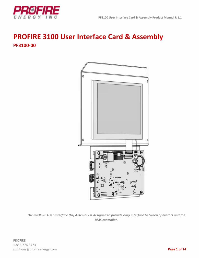
PF3100 User Interface Card & Assembly Product Manual R 1.1 PROFIRE 1.855.776.3473 [email protected] Page 1 of 14 PROFIRE 3100 User Interface Card & Assembly PF3100-00 The PROFIRE User Interface (UI) Assembly is designed to provide easy interface between operators and the BMS controller.
Transcript of PROFIRE 3100 User Interface Card & Assembly€¦ · PF3100 User Interface Card & Assembly Product...
PF3100 User Interface Card & Assembly Product Manual R 1.1
PROFIRE 1.855.776.3473 [email protected] Page 1 of 14
PROFIRE 3100 User Interface Card & Assembly PF3100-00
The PROFIRE User Interface (UI) Assembly is designed to provide easy interface between operators and the
BMS controller.

PF3100 User Interface Card & Assembly Product Manual
PROFIRE 1.855.776.3473 [email protected] Page 2 of 14
1. Introduction .................................................................................................................................................... 3
2. Certifications .................................................................................................................................................. 3
3. Card Information ............................................................................................................................................. 4
4. LCD Information .............................................................................................................................................. 6
5. Backplate ........................................................................................................................................................ 7
6. Wiring Diagrams ............................................................................................................................................. 8
7. Mounting Instructions ................................................................................................................................... 10
8. Enclosure Specifications ................................................................................................................................ 11
9. Instructions for Use ....................................................................................................................................... 11
10. Preventative Maintenance & Inspection ........................................................................................................ 12
11. Important Safety Information ........................................................................................................................ 13
12. PROFIRE Contact Information ........................................................................................................................ 14
PF3100 User Interface Card & Assembly Product Manual
PROFIRE 1.855.776.3473 [email protected] Page 3 of 14
1. Introduction
Functional Description
The PF3100 User Interface (UI) card is the primary access point for commissioning and programming the PF3100
system. The UI card is always installed inside a UIX enclosure. The UI assembly consists of the UI card, the LCD,
and the backplate.
The UI card is designed to be used as part of a PF3100 modular system. For additional information, please refer
to the Hardware Guide corresponding to the cards specific to your application.
Model Types
Model Number
Name Description
PF3100-00A User Interface - Standalone Polyester painted steel enclosure, no other cards included.
PF3100-00B User Interface - Composite with Network Switch Card
Polyester painted steel enclosure, PF3106-00 card included.
PF3100-00C User Interface - Composite with BMS Controller
Polyester painted steel enclosure, PF3101-00 card included.
PF3100-00D User Interface - Composite with BMS Controller Card and Network Switch Card
Polyester painted steel enclosure, PF3101-00 card and PF3106-00 card included.
PF3100-00E User Interface - Composite with BMS Controller Card and Ion Pilot Card
Polyester painted steel enclosure, PF3101-00 card and PF3102-00 card included.
PF3100-00J User Interface - Composite with Modbus Card
Polyester painted steel enclosure, PF3107-00 card included.
PF3100-00K User Interface - Composite with BMS Controller Card and Modbus Card
Polyester painted steel enclosure, PF3101-00 card and PF3107-00 card included.
PF3100-00T User Interface - Composite with Modbus Card and Network Switch Card
Polyester painted steel enclosure, PF3107-00 and PF3106 cards included.
PF3100-00U User Interface - Composite with BMS Card and IO Expansion Card
Polyester painted steel enclosure, PF3101-00 and PF3113-00 cards included.
2. Certifications
PROFIRE strives to ensure that certifications are updated as quickly as they become available for all of our
products.
PF3100 User Interface Card & Assembly Product Manual
PROFIRE 1.855.776.3473 [email protected] Page 4 of 14
User Interface Assembly – Hazardous Location Rating
Certification: Class I, Div 2, Groups A, B, C, D, T4 [CSA C22.2#213:2016 Ed.2]
IEC 61508 SIL2, CSA C22.2#61010-1:2012 Ed.3
UL61010-1:2012 Ed.3+R:29Apr2016
ISA 12.12.01:2016 Ed. 7
The board includes the following symbol:
Caution: possibility of electric shock.
Caution: documentation must be consulted in all cases where this symbol is marked.
3. Card Information
Card Specifications
The ambient temperature rating for the User Interface card is -40°C (-40°F) to +60°C (+140°F).
Type Specifications
PFRN Class Interface
PFRN Power Power Consumer
PFRN Ports 1 PFRN Port
Voltage Input 36 VDC through PFRN
Current Draw 1 A Maximum
Display 5.7" TFT-LCD VGA Color
Battery - UI Clock CR2032, Lithium Coin Cell, 3V, 225mAh
Battery Part Number Panasonic CR2032
Inputs None
Outputs None
PF3100 User Interface Card & Assembly Product Manual
PROFIRE 1.855.776.3473 [email protected] Page 5 of 14
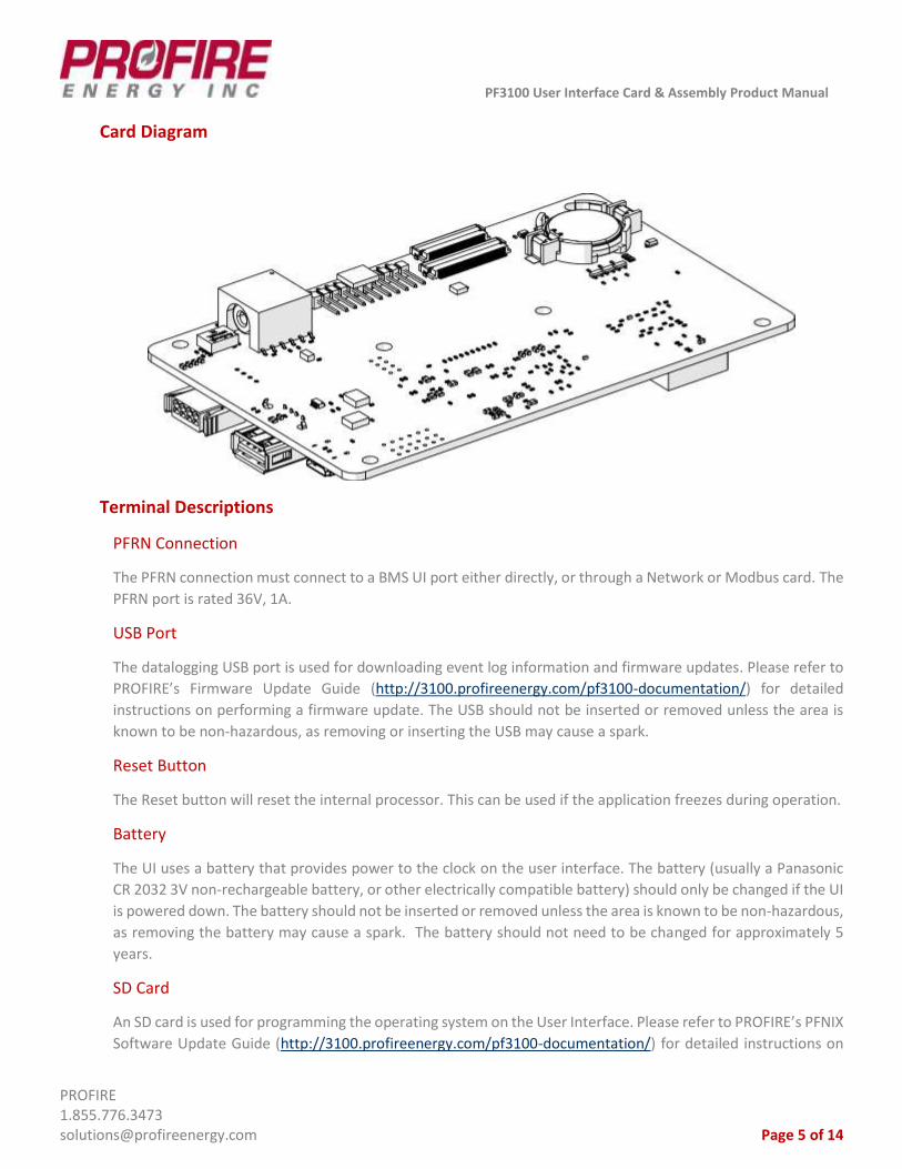
Card Diagram
Terminal Descriptions
PFRN Connection
The PFRN connection must connect to a BMS UI port either directly, or through a Network or Modbus card. The
PFRN port is rated 36V, 1A.
USB Port
The datalogging USB port is used for downloading event log information and firmware updates. Please refer to
PROFIRE’s Firmware Update Guide (http://3100.profireenergy.com/pf3100-documentation/) for detailed
instructions on performing a firmware update. The USB should not be inserted or removed unless the area is
known to be non-hazardous, as removing or inserting the USB may cause a spark.
Reset Button
The Reset button will reset the internal processor. This can be used if the application freezes during operation.
Battery
The UI uses a battery that provides power to the clock on the user interface. The battery (usually a Panasonic
CR 2032 3V non-rechargeable battery, or other electrically compatible battery) should only be changed if the UI
is powered down. The battery should not be inserted or removed unless the area is known to be non-hazardous,
as removing the battery may cause a spark. The battery should not need to be changed for approximately 5
years.
SD Card
An SD card is used for programming the operating system on the User Interface. Please refer to PROFIRE’s PFNIX
Software Update Guide (http://3100.profireenergy.com/pf3100-documentation/) for detailed instructions on
PF3100 User Interface Card & Assembly Product Manual
PROFIRE 1.855.776.3473 [email protected] Page 6 of 14
programming and updating PFNIX software. The SD card should not be inserted or removed unless the area is
known to be non-hazardous, as doing so may cause a spark.
Boot Switch
The boot switch is a mechanism used to recover a corrupted operating system. It allows the user to recover the
operating system (PXFNIX) via an installable SD card.
4. LCD Information
General Specifications
General Specifications
Display Area 115.2mm (4.5 inches) H 86.4mm (3.4 inches) V
Diagonal Size of Display
14cm (5.7 inches)
Display Color 262,144 colors
Pixel 640 pixels (H) 480 pixels (V)
Module Size 144mm (5.7 inches) W 104.6mm (4.11 inches) H 12.3mm (0.48 inches) D
Weight 150 grams (0.33 pounds)
Power Supply Voltage
LCD panel signal processing board: 3.3V LED driver: 12.0V
Backlight LED backlight built in LED driver
Power Consumption
At the maximum luminance control, checkered flag pattern. TBD W
LCD Electrical Specifications
LCD Panel
Parameter Symbol Min. Typ. Max. Unit
Power Supply Voltage VCC 3.00 3.3 3.6 V
Power Supply Current ICC - (130) TBD mA
Permissible Ripple Voltage VRPC - - 100 mVp-p
Logic input voltage for display signals High VDH 0.7VCC - VCC V
Low VDL 0 - 0.3VCC V
LED Driver
Parameter Symbol Min. Typ. Max. Unit
Power Supply Voltage VDD 10.8 12 13.2 V
Power Supply Current IDD - (255) (315) mA
PF3100 User Interface Card & Assembly Product Manual
PROFIRE 1.855.776.3473 [email protected] Page 7 of 14
LCD Diagram
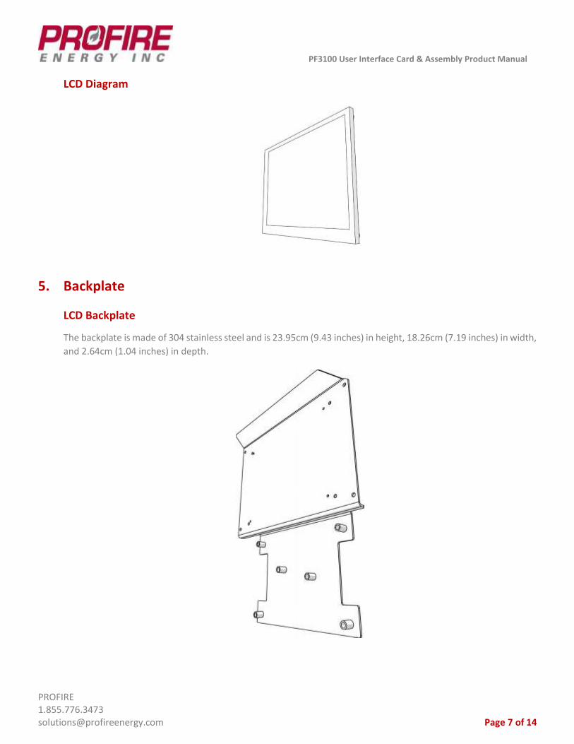
5. Backplate
LCD Backplate
The backplate is made of 304 stainless steel and is 23.95cm (9.43 inches) in height, 18.26cm (7.19 inches) in width,
and 2.64cm (1.04 inches) in depth.
PF3100 User Interface Card & Assembly Product Manual
PROFIRE 1.855.776.3473 [email protected] Page 8 of 14
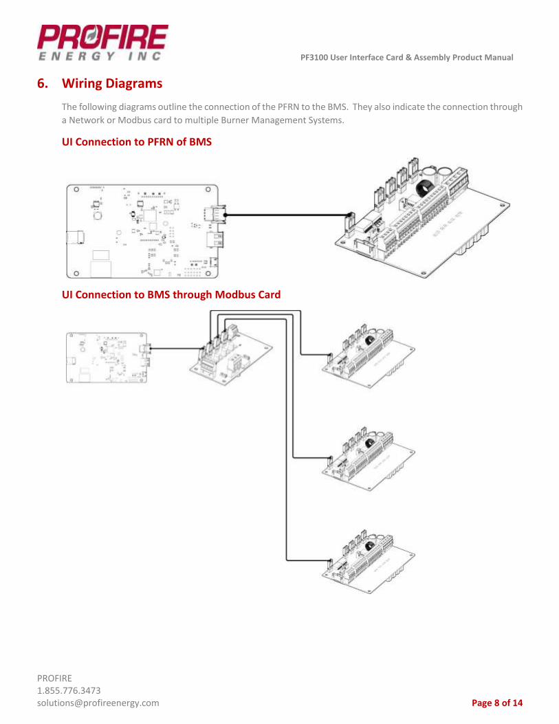
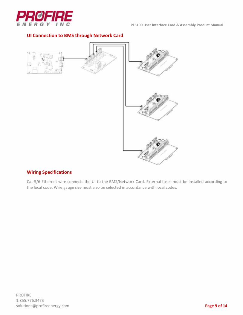
6. Wiring Diagrams
The following diagrams outline the connection of the PFRN to the BMS. They also indicate the connection through
a Network or Modbus card to multiple Burner Management Systems.
UI Connection to PFRN of BMS
UI Connection to BMS through Modbus Card
PF3100 User Interface Card & Assembly Product Manual
PROFIRE 1.855.776.3473 [email protected] Page 9 of 14
UI Connection to BMS through Network Card
Wiring Specifications
Cat-5/6 Ethernet wire connects the UI to the BMS/Network Card. External fuses must be installed according to
the local code. Wire gauge size must also be selected in accordance with local codes.
PF3100 User Interface Card & Assembly Product Manual
PROFIRE 1.855.776.3473 [email protected] Page 10 of 14
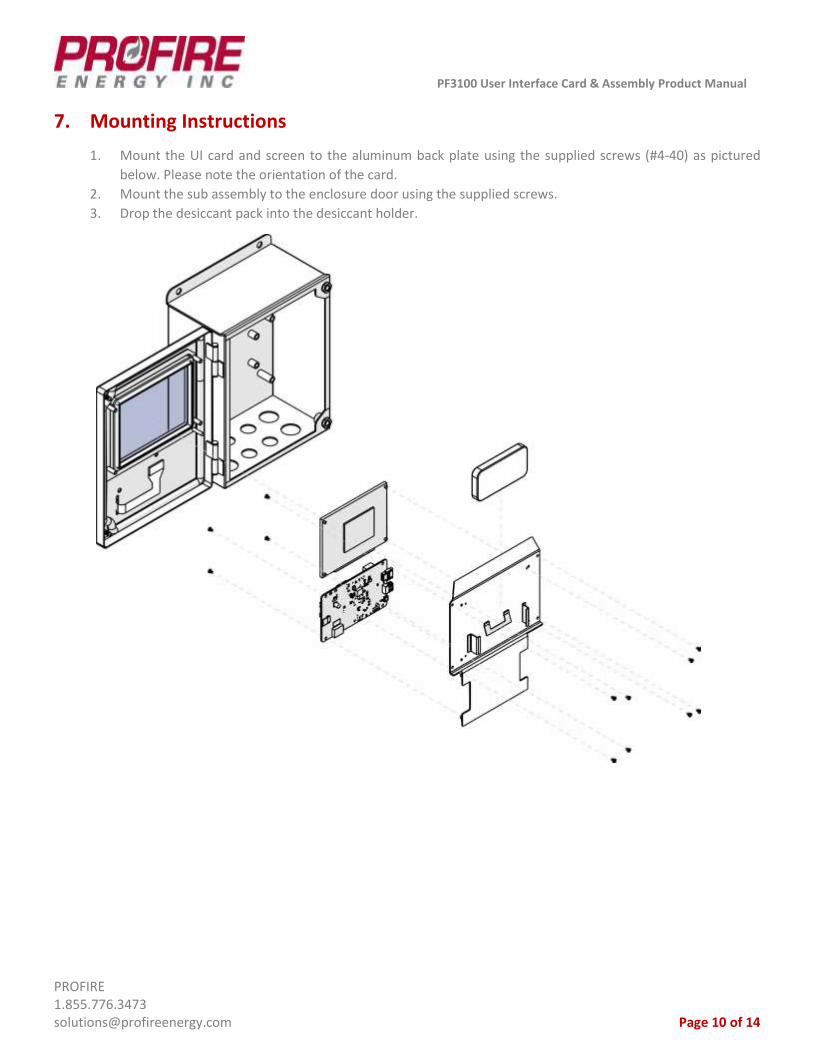
7. Mounting Instructions
1. Mount the UI card and screen to the aluminum back plate using the supplied screws (#4-40) as pictured
below. Please note the orientation of the card.
2. Mount the sub assembly to the enclosure door using the supplied screws.
3. Drop the desiccant pack into the desiccant holder.

PF3100 User Interface Card & Assembly Product Manual
PROFIRE 1.855.776.3473 [email protected] Page 11 of 14
8. Enclosure Specifications
The UI card can be mounted in a fire-proof enclosure that is safe for the area of operation (e.g. – hazardous/non-
hazardous.) The UIX enclosure described below is an example:
Specifications UIX Enclosure
Dimensions Height 30.9cm (12.15 inches) Width 23.4cm (9.23 inches) Depth 13.4cm (5.28 inches)
Hazloc Rating Class I Div 2, IP66
Mounting Channel Bar or Direct Mount
Enclosure Construction Poly Painted Steel
Operating Temperature -40°C (-40°F) to 60°C (140°F)
Storage Temperature -40°C (-40°F) to 60°C (140°F)
9. Instructions for Use
The User Interface (UI) Card is designed to be used with a certified BMS controller as part of the PF3100 platform.
The UI hosts an application that allows the operator to commission the PF3100 Burner Management System. The
UI can display status information about the appliance including alarms, temperatures, and setpoints, amongst
many other items.
The UI is required to commission the system, but it is not required to run the system. When the UI is not connected
to the BMS appliance, it is referred to as “headless operation.” This means that the system will run even if the UI
is not working, although obviously this is not optimal.
Detailed instructions for specific uses of the user interface application itself may be found in the following
documents:
➢ PF3100 Quick User Guide
➢ PF3100 Software Setup Guide
➢ PF3100 Firmware Update Guide
➢ PF3100 User Manual.
These documents can be found at the following link:
http://3100.profireenergy.com/pf3100-documentation/

PF3100 User Interface Card & Assembly Product Manual
PROFIRE 1.855.776.3473 [email protected] Page 12 of 14
10. Preventative Maintenance & Inspection
In order to ensure that the User Interface card works correctly and efficiently, the following maintenance and
inspection procedures should be followed:
➢ Confirm that the PFRN cable is connected securely.
➢ Ensure that all wires are connected correctly.
➢ Routinely check for corrosion.
➢ Minimize copper wire exposure.
➢ Wires must not be frayed or worn, and all insulation must be intact.
➢ Ensure that no moisture or condensation is apparent on the board or within the enclosure.
➢ Check that the board does not show any sign of mechanical damage (e.g. – damage from impact from a
dropped item such as a screw driver).
➢ Check that the board does not show any sign of electrical damage. This means that no components should
be burnt or damaged in any way.
➢ Check that an SD card is not present in the UI during normal operation. The SD card is only used to update
the application and should not be installed during normal operation.
➢ Ensure that the battery is not corroded and replace if necessary, when safe to do so.
➢ Visually check that the LCD screen is operating correctly.
➢ Check that the keypad buttons operate correctly, and that the ribbon cable connection is attached securely.
The keypad can be tested by following the instructions for UI testing as listed below.
➢ Confirm that the temperature of the board is within ambient temperature operating limits.
➢ Confirm that the enclosure is secured.
➢ Check that the device is not subject to excessive vibration.
➢ Routine inspections should be performed on all equipment. If any abnormality is found, corrective actions
should be taken. If the abnormality cannot be corrected, contact PROFIRE as soon as possible.
➢ A qualified technician should perform any tests necessary to confirm that the equipment is still in a safe
condition. The board may be tested for correct operation in a safe environment as follows:
• Power the UI down.
• Hold the Multi Button.
• Power the UI up and keep holding the Multi button until the boot screen appears.
• Select the UI test.
• Run the UI test. This will check the screen, LEDs, RTC, and keypad.
• Upon completion: the user will be prompted to update the PFNIX version. If testing only, do not
update the PFNIX version, simply decline the request.

PF3100 User Interface Card & Assembly Product Manual
PROFIRE 1.855.776.3473 [email protected] Page 13 of 14
Cleaning
If the card becomes dirty it can be cleaned with compressed air. Do NOT use solvents, cleaners, or liquids to clean
the board. Caution must be exercised when cleaning the board in order to prevent damage from ESD (electrostatic
discharge).
11. Important Safety Information
Before installing the PF3100 User Interface assembly, please review the list of warnings below. Product use in a
manner not specified by PROFIRE is not recommended. Failure to observe the following warnings may result in
death, electrocution, property damage, product damage, government fines, or malfunction of the product itself.
Warning: Explosion Hazard
➢ Do not disconnect while circuit is live unless area is known to be non-hazardous or equivalent.
➢ Substitution of components may impair suitability for specified zones.
➢ Do not service unless the area is known to be non-hazardous.
➢ Do not open when energized.
➢ Installation and use must conform to the directions in this guide.
Installation Warnings
➢ Ensure that the PF3100 enclosures are securely closed each time after opening the enclosure. This protects
the internal circuitry from moisture damage and other environmental concerns. Moisture damage is not
covered by the product warranty.
➢ Do not connect wires or handle the device when powered.
➢ Do not disassemble or modify the assembly in any way. The board is not field reparable and must be sent
back to PROFIRE for replacement if damaged.
➢ Installation of the card should be performed according to the local electrical code by a capable electrician
using de-energized wire. Live modifications should NOT be performed.
Other Warnings
➢ Equipment MUST be installed with a PF3100 controller.
➢ Do not remove or install the battery while the system is live, or if the area is known to be hazardous.
➢ Do not remove or install a USB stick if the area is known to be hazardous.
➢ Equipment must be housed inside a fire-proof enclosure that is suitable for the environment and can only be
accessed with the use of a tool.
➢ Evaluation for the UI card as part of the system assembly is required after final installation.
➢ P3 terminal can only be connected to keypads that are considered a simple apparatus, or alternatively
connects to Sytek Enterprises Inc. P-MS-RR5NEO-006-SPA-14.12.18 Rev 1.4 keypad.
➢ Display and keypad shall be installed in factory. Not for field connection.

PF3100 User Interface Card & Assembly Product Manual
PROFIRE 1.855.776.3473 [email protected] Page 14 of 14
12. PROFIRE Contact Information
If you have any concerns or questions about this product, please contact PROFIRE as follows:
U.S.
1.801.796.5127
321 South, 1250 West Suite 1
Lindon, UT
84042, USA
CANADA
1.780.960.5278
Box 3313, Bay 12, 55 Alberta Ave
Spruce Grove, AB
T7X 3A6, Canada
http://www.profireenergy.com/