Professional COPYRIGHTED MATERIAL Foundations
16
P A R T I Professional Foundations T he information contained in Chapters 1 through 6 is intended to establish the fundamentals for those practicing in the field of architecture. These chapters will shape your understanding of an office, the practice, the stages, and the drawings of architecture. The concept of a good foundation applies to both structures and individuals: without a solid foundation, failure is imminent. On this basis, the groundwork for architecture—the office and specific aspects of construction documents—will be the rock on which these chapters are founded. Chapter 1 The Office Chapter 2 Standards and Techniques, Metrification, Hand Drafting, and Computer-aided Drafting Chapter 3 BIM, Revit, and Human Concerns Chapter 4 Sustainable/Green Architecture Chapter 5 Construction Materials and Methods Chapter 6 Initial Preparation Phase for Construction Documents COPYRIGHTED MATERIAL
Transcript of Professional COPYRIGHTED MATERIAL Foundations
P A R T
IProfessional Foundations
The information contained in Chapters 1 through 6 is intended to establish the fundamentals for those practicing in the field of architecture. These
chapters will shape your understanding of an office, the practice, the stages, and the drawings of architecture. The concept of a good foundation applies to both
structures and individuals: without a solid foundation, failure is imminent. On this basis, the groundwork for architecture—the office and specific aspects of construction documents—will be the rock on which these chapters are founded.
Chapter 1 The OfficeChapter 2 Standards and Techniques, Metrification, Hand Drafting, and Computer-aided DraftingChapter 3 BIM, Revit, and Human ConcernsChapter 4 Sustainable/Green ArchitectureChapter 5 Construction Materials and MethodsChapter 6 Initial Preparation Phase for Construction Documents
ch01.indd 1 9/30/2011 5:38:53 PM
COPYRIG
HTED M
ATERIAL

ch01.indd 2 9/30/2011 5:38:53 PM

c h a p t e r
1THE OFFICE
ch01.indd 3 9/30/2011 5:38:56 PM
4 THE OFFICE
J THE PHYSICAL OFFICEThe physical plant of the architectural office has begun to take on a new look. The firm that once worked only in a local community now has a global reach. Where proximity once limited the opportunity for a client to access global talent, the computer, transportation, and communications technology allow for interviews based on architectural ability rather than proximity. It is no lon-ger necessary to select an architect in one’s immediate community, because technology allows for virtual meet-ings around the globe.
It is not one firm, but many that may construct draw-ings in a collaborative effort based on the ebb and flow of the size of the project. The result is that any firm, of any size, can join another to achieve an assigned task. Today, network does more than just describe a system of communication; it also describes the architect’s role. An individual may work on a drawing halfway around the world, while at the project location it is the middle of the night. Redlines, or corrected drawings, can be marked up electronically and sent via email for the next work shift, resulting in two times the production in half the normal time. An architecture firm that specializes in design can partner with another firm that specializes in construction documents.
Architecture is a small crafts industry in which most offices employ one to four people. A home office may also be part of the office structure. A single drafter may be hired by two or more firms, in which case the of-fice becomes a docking station for electronic project information, such as construction documents. Because digital images can be rapidly moved electronically, one need not live within the city or even the country where the project will be sited; one can send documents across the world instantly. In the traditional architec-tural firm, an architect in a firm leads the project and distributes the work among the staff within the firm. When a workload jam arises, the architect may hire a subcontractor to aid in development of the required drawings.
J OFFICE PRACTICE AND HOW IT MAY BE STRUCTURED
The Firm
The way in which an architectural firm is structured, and the office practices it employs, depend on the magnitude and type of its projects, the number of per-sonnel, and the philosophies the architects hold with regard to office practice procedures. Normally, the ar-chitect or architects are the owners and/or principals of the practice.
Although a small firm will differ from a medium, large, or extra-large firm, many of the functions will be the same. In all firms, a licensed architect will oversee staff as a direct supervisor. In each firm, services such as programming (determining the objectives of the proj-ect), space planning (the layout of the furnishings and fixtures), feasibility studies, site analysis, coordination, scheduling, and architectural design will be provided according to the firm’s contract with the client. As a firm’s size increases, one major factor does change: that of documentation of directives and communications. Of course, it is imperative for a firm of any size to track its work and communications with clients. However, as the firm size increases, the documentation becomes critical; as larger project teams mobilize to perform tasks, any lack of documentation can result in reworking projects and significant loss of revenue.
In general, an architectural office can be separated into three main departments: the administration depart-ment, the design department, and the production de-partment. The principal or principals oversee all three departments in addition to their other duties.
Administration Department
The administration department handles all communica-tions between the architectural firm and its clients on items such as contracts, fee schedules, billing for ser-vices, and similar matters. This department handles all secretarial duties, including all written correspondence, payment of operating costs, accounting procedures, pay-ing salaries, marketing, and maintaining project records relating to individual project costs and procedures. This department may also handle human resources (HR) functions, including management of the firm’s staff.
Under the purview of administration, many firms also include a marketing department. Tasks for this de-partment might include development and maintenance of a web site, creation and dissemination of publica-tion materials, assembly of competition entries, and development of promotional materials. Marketing is used to focus a firm on a particular area of work and take advantage of opportunities that may arise for a specific project type that the firm prefers or in which it specializes.
Design Department
The design department is normally headed by a prin-cipal architect and/or an associate architect. This per-son or persons meets with the client to determine the requirements of a project, the economics of the project, and the anticipated time frame for completing the con-struction documents. These initial concerns determine
ch01.indd 4 9/30/2011 5:38:56 PM
OFFICE PRACTICE AND HOW IT MAY BE STRUCTURED 5
the program for the project. The head or heads of this department delegate various work phases of a project to other staff members. The number of staff members de-pends on the size of the practice and the magnitude of the projects. Staff members may be assigned to teams or groups in their area of expertise for specific projects. A team takes a project from the initial schematic design concept, through design development, to the completed construction drawings and specifications. These stages may include model building, renderings, coordination among all consulting engineers to meet their individual job requirements, job billing, and reproduction respon-sibilities. The leader of a project and of the design team staff is designated the project architect. A project archi-tect’s responsibilities are to develop a “game plan” for a specific project, which will include:
1. Design studies, philosophy, and concept 2. Initial structural considerations 3. Exterior and interior materials 4. Municipality and building code requirements 5. Architectural committee reviews 6. Building equipment requirements, LEED (Leadership
in Energy and Environmental Design) 7. Manufacturing resources 8. Selection of required engineering consultants (soils/
geology, structural, mechanical, etc.) 9. Planned man-hours, time sheets, and billing dates 10. Office standards for the representation of items on
the working drawings, such as symbols, wall delin-eations, and other graphic depictions
Production Department
The production department, under the supervision of a project architect, prepares all the phases for a set of completed construction drawings. Working drawings may be produced by a senior drafter, intermediate draft-er, or junior drafter under the supervision of a licensed architect. These staff members and the project architect or job captain work as a team to make the transition from the approved preliminary drawings to the comple-tion and implementation of the working drawings. The transition from the approved preliminary drawings to the development of the working drawings is elaborated in Part II of this book. Other chapters provide step-by-step procedures on how different sections of the work-ing drawings are developed: the site and grading plan, foundation plan, floor plan, building sections, exterior elevations, roof and framing plans, interior elevations, architectural details, and schedules. During the process and completion of the various sections, the project ar-chitect and/or job captain constantly reviews the draw-ings for clarity, accuracy, and craftsmanship of detail-
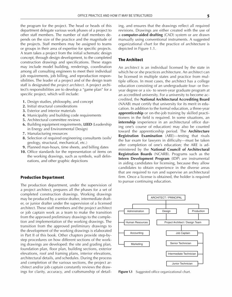
ing, and ensures that the drawings reflect all required revisions. Drawings are either created with the use of a computer-aided drafting (CAD) system or are drawn manually using conventional instruments. A suggested organizational chart for the practice of architecture is depicted in Figure 1.1.
The Architect
An architect is an individual licensed by the state in which he or she practices architecture. An architect can be licensed in multiple states and practice from mul-tiple offices. In most cases, the architect has a college education consisting of an undergraduate four- or five-year degree or a six- to seven-year graduate program at an accredited university. For a university to become ac-credited, the National Architectural Accrediting Board (NAAB) must certify that university for its merit in edu-cation. In addition to the formal education, a three-year apprenticeship or on-the-job training by skilled practi-tioners in the field is required. In some situations, an internship (experience in an architectural office dur-ing one’s course of education) may also be counted toward the apprenticeship period. The Architecture Registration Examination (ARE)—testing that rivals the bar exam for lawyers in difficulty—must be taken after completion of one’s education; the ARE is ad-ministered by the National Council of Architectural Registration Boards (NCARB). Programs such as the Intern Development Program (IDP) are instrumental in aiding candidates for licensing, because they allow candidates to obtain experience in the diverse areas that are required to run and supervise an architectural firm. Once a license is obtained, the holder is required to pursue continuing education.
Figure 1.1 Suggested office organizational chart.
ARCHITECT / PRINCIPAL
ProductionDesignAdministration
Human Resources
Accounting
Marketing
Project Architect / Design Team
Job Captain
Senior Technician
Intermediate Technician
Junior Technician
ch01.indd 5 9/30/2011 5:39:02 PM
6 THE OFFICE
J RESOURCE LIBRARYResearch
To find and detail all the equipment that is required for a structure (plumbing, hardware, finishes, and so forth), it is necessary to have access to the various manufacturing resources for specific products. The most widely used product information source is the Internet. Electronic access allows architects and engineers to survey the re-sources available and select the equipment that will best enable the function of a building. Such equipment may be available from a myriad of different manufacturers, and range from conveying systems to window and doors and the like. Samples can be included in a firm’s in-house library. Most of the literature found in electronic
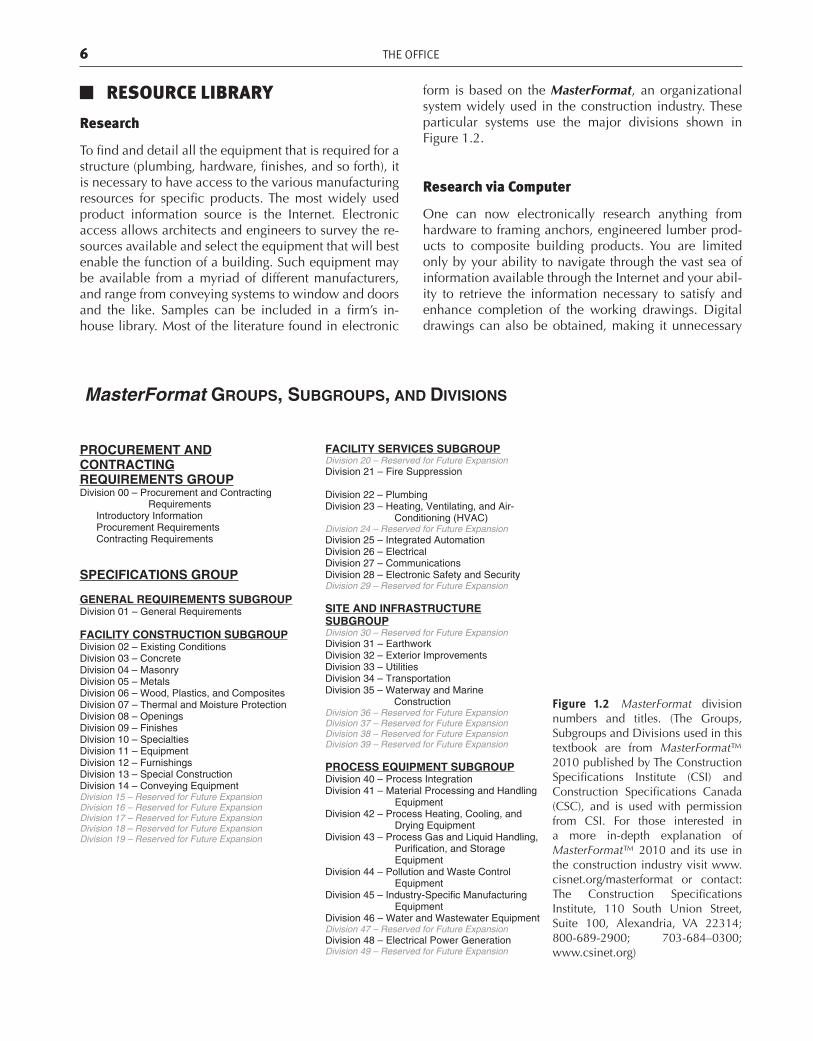
Figure 1.2 MasterFormat division numbers and titles. (The Groups, Subgroups and Divisions used in this textbook are from MasterFormat™ 2010 published by The Construction Specifications Institute (CSI) and Construction Specifications Canada (CSC), and is used with permission from CSI. For those interested in a more in-depth explanation of MasterFormat™ 2010 and its use in the construction industry visit www.cisnet.org/masterformat or contact: The Construction Specifications Institute, 110 South Union Street, Suite 100, Alexandria, VA 22314; 800-689-2900; 703-684–0300; www.csinet.org)
Applications Guide
MasterFormat GROUPS, SUBGROUPS, AND DIVISIONS
PROCUREMENT ANDCONTRACTINGREQUIREMENTS GROUPDivision 00 – Procurement and Contracting
Requirements Introductory Information Procurement Requirements Contracting Requirements
SPECIFICATIONS GROUP
GENERAL REQUIREMENTS SUBGROUPDivision 01 – General Requirements
FACILITY CONSTRUCTION SUBGROUPDivision 02 – Existing Conditions Division 03 – Concrete Division 04 – Masonry Division 05 – Metals Division 06 – Wood, Plastics, and Composites Division 07 – Thermal and Moisture Protection Division 08 – Openings Division 09 – Finishes Division 10 – Specialties Division 11 – Equipment Division 12 – Furnishings Division 13 – Special Construction Division 14 – Conveying Equipment Division 15 – Reserved for Future Expansion Division 16 – Reserved for Future Expansion Division 17 – Reserved for Future Expansion Division 18 – Reserved for Future Expansion Division 19 – Reserved for Future Expansion
FACILITY SERVICES SUBGROUPDivision 20 – Reserved for Future Expansion Division 21 – Fire Suppression
Division 22 – Plumbing Division 23 – Heating, Ventilating, and Air-
Conditioning (HVAC) Division 24 – Reserved for Future Expansion Division 25 – Integrated Automation Division 26 – Electrical Division 27 – Communications Division 28 – Electronic Safety and Security Division 29 – Reserved for Future Expansion
SITE AND INFRASTRUCTURESUBGROUPDivision 30 – Reserved for Future Expansion Division 31 – Earthwork Division 32 – Exterior Improvements Division 33 – Utilities Division 34 – Transportation Division 35 – Waterway and Marine
Construction Division 36 – Reserved for Future Expansion Division 37 – Reserved for Future Expansion Division 38 – Reserved for Future Expansion Division 39 – Reserved for Future Expansion
PROCESS EQUIPMENT SUBGROUPDivision 40 – Process Integration Division 41 – Material Processing and Handling
Equipment Division 42 – Process Heating, Cooling, and
Drying Equipment Division 43 – Process Gas and Liquid Handling,
Purification, and Storage Equipment
Division 44 – Pollution and Waste Control Equipment
Division 45 – Industry-Specific Manufacturing Equipment
Division 46 – Water and Wastewater Equipment Division 47 – Reserved for Future Expansion Division 48 – Electrical Power Generation Division 49 – Reserved for Future Expansion
form is based on the MasterFormat, an organizational system widely used in the construction industry. These particular systems use the major divisions shown in Figure 1.2.
Research via Computer
One can now electronically research anything from hardware to framing anchors, engineered lumber prod-ucts to composite building products. You are limited only by your ability to navigate through the vast sea of information available through the Internet and your abil-ity to retrieve the information necessary to satisfy and enhance completion of the working drawings. Digital drawings can also be obtained, making it unnecessary
ch01.indd 6 9/30/2011 5:39:04 PM
ARCHITECT/CLIENT RELATIONSHIP 7
to draw configurations for products such as window pro-files, stair rails, and so on. Caution must be taken when you utilize Internet details, though; we suggest that you do not simply copy them, because use of a copy makes you liable for the result or outcome of use of the detail. Always verify the accuracy and appropriateness of a de-tail before you adopt it as your own.
Manufacturers’ Literature
A wealth of product information is available directly from manufacturers, in the form of brochures, pam-phlets, catalogs, manuals, and hardbound books. Actual samples of their products may also be obtained. The in-formation available may include:
1. Advantages of a particular product over others 2. How the system works or is assembled 3. Necessary engineering 4. Detailed drawings 5. Special design features 6. Colors, textures, and patterns 7. Safety tests 8. Dimensioning 9. Installation procedures
Adapt this information to your particular needs in your geographical location.
Other Reference Sources
Retail sources such as major book publishers produce architectural reference books. Many art supply and draft-ing supply stores also carry reference materials. Public libraries may have a variety of professional reference materials, including books, journals, and trade maga-zines. Colleges and universities offering architecture courses usually have a wealth of architectural resource materials. An example of a highly technical resource is the AIA Architectural Graphics Standards published by John Wiley & Sons. This book is found in almost all ar-chitectural offices. In addition, the American Institute of Architects (AIA) publishes standards and guidelines for architects to utilize as well.
J PROFESSIONAL ORGANIZATIONSProfessional organizations can be an asset to the busi-ness performance and office functions of an architec-tural firm. The AIA is an example of a professional orga-nization that will provide members with recommended documents, including client/architect contractual agree-ments, client/contractor agreements, and many others. The AIA also provides recommended guidelines relative
to fee schedules and disbursements, construction docu-ments, building specifications, and construction obser-vation procedures and documentation.
Ethical procedures and office practice methods are recommended and defined as part of the many docu-ments available from the AIA.
It is recommended that associate architects and em-ployees at the various technical levels become involved with a professional organization for a number of reasons, but primarily to stay aware of current technical informa-tion and activities within the architectural profession. The AIA also offers programs and directions for those in an internship phase of their careers. Student associate member programs available through the AIA provide an overall view of the architectural profession.
Other professional organizations for students of ar-chitecture can be found through students’ colleges and universities.
J ARCHITECT/CLIENT RELATIONSHIPWorking Relationship
The relationship between the architect and the cli-ent will vary. In general, the relationship for a specific building project and the responsibilities and procedures necessary to accomplish the goals of the project will be initiated with the selection of the architect. After the ar-chitect is selected, the architect and the client enter into a contract, which defines the services to be performed and the responsibilities of the architect and the client. Many states require architects to use a written contract when providing professional services.
After the contractual agreement is signed and a re-tainer fee is received, the architect reviews the building site and confers with the client to determine the goals of the building project. After establishing the project goals, there will be meetings with the governing agencies, such as the planning department, the building department, and architectural committees. The primary goal of the architectural team at this point is to initiate the prelimi-nary planning and design phases.
Most architectural contracts and agreements include provisions for the architect and the consulting engineers to observe construction of the project during the various building stages. It is a standard practice for the architects to visit the site, determine if the construction is progress-ing correctly, and report their findings.
Schematic Design and Reviews
The next step in the architect/client relationship is the architect’s presentation of the schematic design (SD) for the project. After the client’s initial review of the planning
ch01.indd 7 9/30/2011 5:39:04 PM
8 THE OFFICE
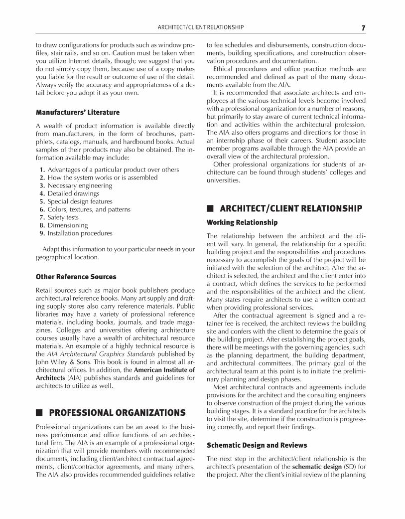
and design for the project, some revisions and alterations may be made to the design. In this case, the drawings are revised and presented again to the client for his or her approval. After the client approves the schematic design, the architect consults with and presents the schematic drawings to the various governing agencies, such as the planning department, for their review and comments. Any revisions and alterations that may be required by any of the agencies are executed and again reviewed by the client, and approved. The schematic drawings are of-ten used to estimate the initial construction costs, which
Figure 1.3 Schematic site design drawing. (Courtesy of Nicole Shweiri.)
are also submitted for client review and approval. Using BIM or Revit, it is possible to provide the client with a more accurate estimate of cost, because these programs incorporate the materials and methods of construction in the drafting process.
In the SD phase, a conceptual site plan and floor plan of the building areas are reviewed for the building ori-entation and the preservation of existing landscaping elements such as trees, topography, and other site con-ditions. Figure 1.3 shows an example of a conceptual site and building plan. The client for this project desires
ch01.indd 8 9/30/2011 5:39:05 PM
ARCHITECT/CLIENT RELATIONSHIP 9
to build a three-bedroom residence. The site, which is located in a beach community, is a small property. The lot is located on a corner where side and front-yard set-backs use most of the lot area and the garage must be ad-ditionally set back to allow for a driveway with visibility.
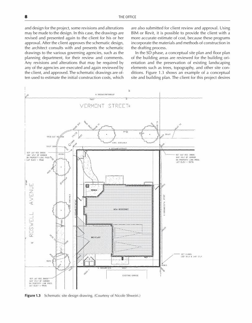
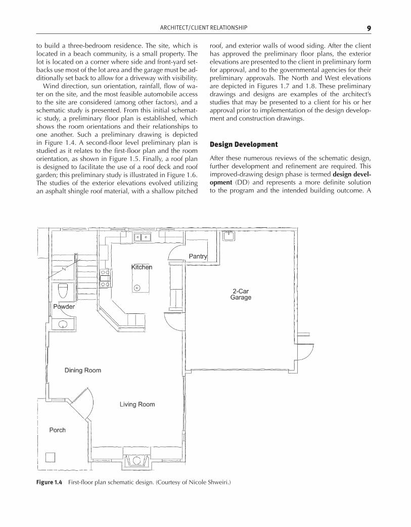
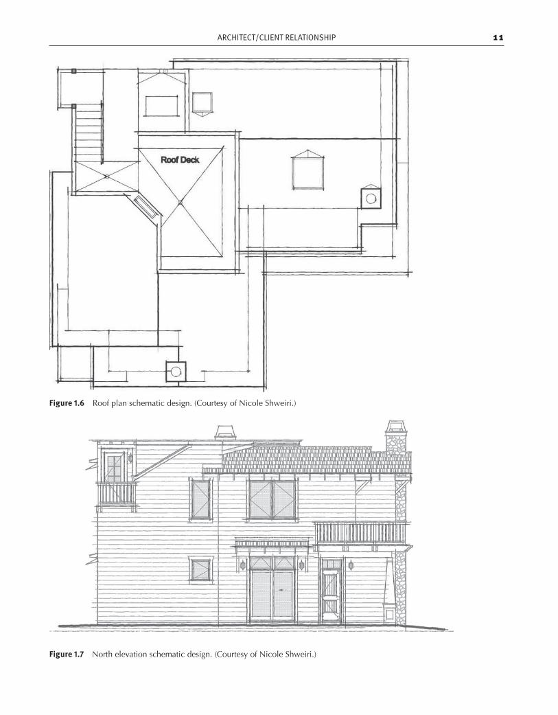
Wind direction, sun orientation, rainfall, flow of wa-ter on the site, and the most feasible automobile access to the site are considered (among other factors), and a schematic study is presented. From this initial schemat-ic study, a preliminary floor plan is established, which shows the room orientations and their relationships to one another. Such a preliminary drawing is depicted in Figure 1.4. A second-floor level preliminary plan is studied as it relates to the first-floor plan and the room orientation, as shown in Figure 1.5. Finally, a roof plan is designed to facilitate the use of a roof deck and roof garden; this preliminary study is illustrated in Figure 1.6. The studies of the exterior elevations evolved utilizing an asphalt shingle roof material, with a shallow pitched
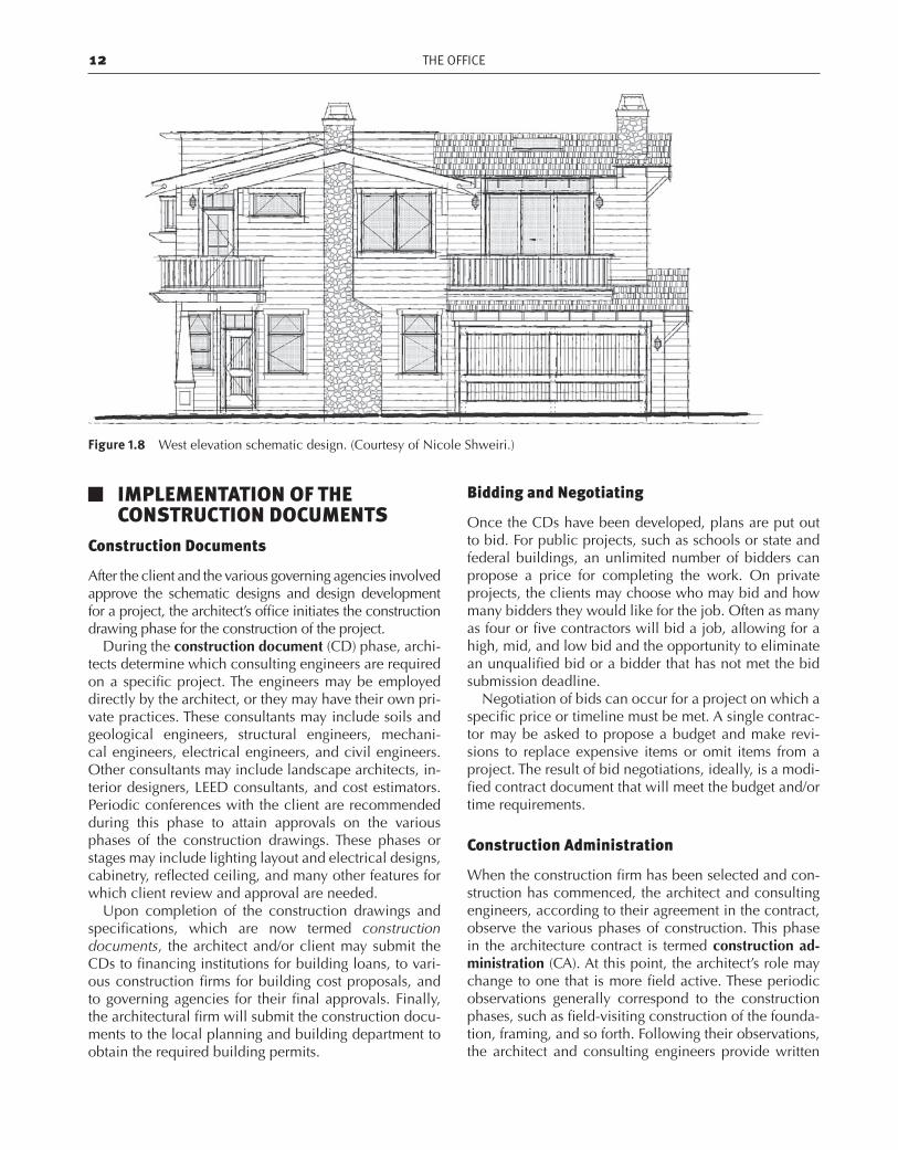
roof, and exterior walls of wood siding. After the client has approved the preliminary floor plans, the exterior elevations are presented to the client in preliminary form for approval, and to the governmental agencies for their preliminary approvals. The North and West elevations are depicted in Figures 1.7 and 1.8. These preliminary drawings and designs are examples of the architect’s studies that may be presented to a client for his or her approval prior to implementation of the design develop-ment and construction drawings.
Design Development
After these numerous reviews of the schematic design, further development and refinement are required. This improved-drawing design phase is termed design devel-opment (DD) and represents a more definite solution to the program and the intended building outcome. A
Figure 1.4 First-floor plan schematic design. (Courtesy of Nicole Shweiri.)
ch01.indd 9 9/30/2011 5:39:05 PM
10 THE OFFICE
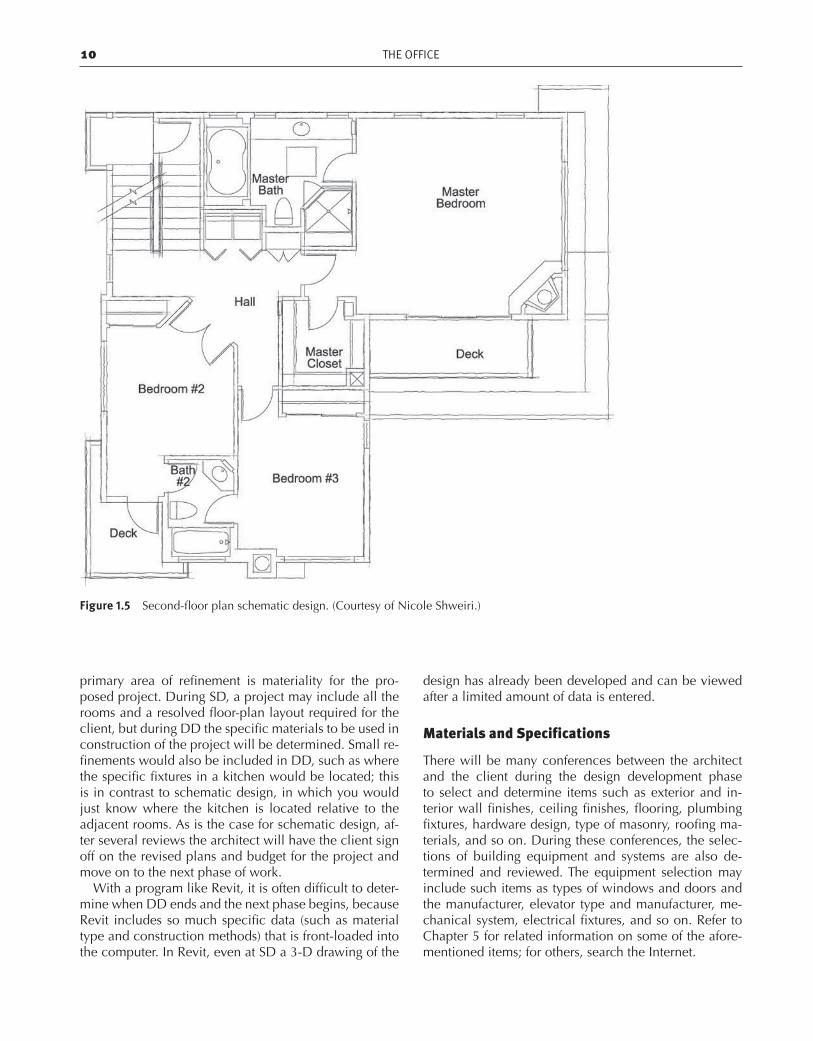
Figure 1.5 Second-floor plan schematic design. (Courtesy of Nicole Shweiri.)
primary area of refinement is materiality for the pro-posed project. During SD, a project may include all the rooms and a resolved floor-plan layout required for the client, but during DD the specific materials to be used in construction of the project will be determined. Small re-finements would also be included in DD, such as where the specific fixtures in a kitchen would be located; this is in contrast to schematic design, in which you would just know where the kitchen is located relative to the adjacent rooms. As is the case for schematic design, af-ter several reviews the architect will have the client sign off on the revised plans and budget for the project and move on to the next phase of work.
With a program like Revit, it is often difficult to deter-mine when DD ends and the next phase begins, because Revit includes so much specific data (such as material type and construction methods) that is front-loaded into the computer. In Revit, even at SD a 3-D drawing of the
design has already been developed and can be viewed after a limited amount of data is entered.
Materials and Specifications
There will be many conferences between the architect and the client during the design development phase to select and determine items such as exterior and in-terior wall finishes, ceiling finishes, flooring, plumbing fixtures, hardware design, type of masonry, roofing ma-terials, and so on. During these conferences, the selec-tions of building equipment and systems are also de-termined and reviewed. The equipment selection may include such items as types of windows and doors and the manufacturer, elevator type and manufacturer, me-chanical system, electrical fixtures, and so on. Refer to Chapter 5 for related information on some of the afore-mentioned items; for others, search the Internet.
ch01.indd 10 9/30/2011 5:39:06 PM
ARCHITECT/CLIENT RELATIONSHIP 11
Figure 1.7 North elevation schematic design. (Courtesy of Nicole Shweiri.)
Figure 1.6 Roof plan schematic design. (Courtesy of Nicole Shweiri.)
ch01.indd 11 9/30/2011 5:39:06 PM
12 THE OFFICE
Figure 1.8 West elevation schematic design. (Courtesy of Nicole Shweiri.)
J IMPLEMENTATION OF THE CONSTRUCTION DOCUMENTS
Construction Documents
After the client and the various governing agencies involved approve the schematic designs and design development for a project, the architect’s office initiates the construction drawing phase for the construction of the project.
During the construction document (CD) phase, archi-tects determine which consulting engineers are required on a specific project. The engineers may be employed directly by the architect, or they may have their own pri-vate practices. These consultants may include soils and geological engineers, structural engineers, mechani-cal engineers, electrical engineers, and civil engineers. Other consultants may include landscape architects, in-terior designers, LEED consultants, and cost estimators. Periodic conferences with the client are recommended during this phase to attain approvals on the various phases of the construction drawings. These phases or stages may include lighting layout and electrical designs, cabinetry, reflected ceiling, and many other features for which client review and approval are needed.
Upon completion of the construction drawings and specifications, which are now termed construction documents, the architect and/or client may submit the CDs to financing institutions for building loans, to vari-ous construction firms for building cost proposals, and to governing agencies for their final approvals. Finally, the architectural firm will submit the construction docu-ments to the local planning and building department to obtain the required building permits.
Bidding and Negotiating
Once the CDs have been developed, plans are put out to bid. For public projects, such as schools or state and federal buildings, an unlimited number of bidders can propose a price for completing the work. On private projects, the clients may choose who may bid and how many bidders they would like for the job. Often as many as four or five contractors will bid a job, allowing for a high, mid, and low bid and the opportunity to eliminate an unqualified bid or a bidder that has not met the bid submission deadline.
Negotiation of bids can occur for a project on which a specific price or timeline must be met. A single contrac-tor may be asked to propose a budget and make revi-sions to replace expensive items or omit items from a project. The result of bid negotiations, ideally, is a modi-fied contract document that will meet the budget and/or time requirements.
Construction Administration
When the construction firm has been selected and con-struction has commenced, the architect and consulting engineers, according to their agreement in the contract, observe the various phases of construction. This phase in the architecture contract is termed construction ad-ministration (CA). At this point, the architect’s role may change to one that is more field active. These periodic observations generally correspond to the construction phases, such as field-visiting construction of the founda-tion, framing, and so forth. Following their observations, the architect and consulting engineers provide written
ch01.indd 12 9/30/2011 5:39:07 PM
BUILDING 13
reports to the client and contractor describing their ob-servations, along with any recommendations or altera-tions they deem necessary for the success of the project. Performing site visits, making field revisions and clari-fications, and responding to requests for information (RFI) enhance opportunities for better design, budget, and schedule results.
At the completion of the project, the architect and consultants make a final inspection of the construction of the building and prepare a punch list. This punch list, which is in written form, includes graphics indicating to the client and construction firm any revisions, reports, or alterations the architect or consultant deems pertinent and reasonable for a successful building project. After the construction firm makes the revisions, the architect and the consultants again inspect the project. If accept-able, a final notice of approval is sent to the client and the construction firm.
J BUILDINGBuilding Codes
The purpose of building codes is to safeguard life, health, and the public welfare. Building codes are con-tinually being revised to incorporate additional regula-tions based on tests or conditions caused by catastrophic events, such as hurricanes, earthquakes, and fires. In most cases, the governing building codes are similar in organization and context.
The requirements of various agencies and codes are of paramount influence in the design and detailing of today’s structures. A great number of codes govern and regulate the many elements that are integrated into the construction of a building. The major codes that are used in the design and detailing of buildings are the building code, mechanical code, electrical code, fire code, energy code, and accessibility design criteria for compliance with the Americans with Disabilities Act (ADA).
Procedures for Use of Building Codes
Step I. Building use and occupancy. The first step is to classify the building use and to determine the oc-cupancy group for the building. When the occupancy classification has been determined, the building is as-signed a group designation letter, which determines the description of the occupancy and the group it falls under.
Step II. Fire-rated wall assemblies. Most codes provide a chapter on acceptable fire-resistive standards for assemblies, so that the architect is able to select an assembly that satisfies his or her specific condition. For example, a one-hour fire-rated wall is constructed
with 2″ × 4″ wood stud partition with 5/8″ type “X” gypsum wallboard on both sides.
Step III. Building location on the site. The location of the building on the site and the clearances to the prop-erty lines and other structures on the site determine the fire-resistant construction of the exterior walls. The openings are based on the distances from the property lines and other structures.
Step IV. Allowable floor areas. The next step is to de-termine the proposed and allowable floor areas of the building based on the occupancy group, such as the-ater or assembly room, and the type of construction.
Step V. Height and the number of stories or floors in the building. The architect computes the maximum height of the building and determines the number of stories and/or floors. The maximum number of stories and the height of the building are determined by the building occupancy and the type of construction.
Code Influence on Building Design
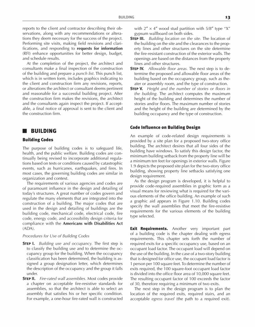
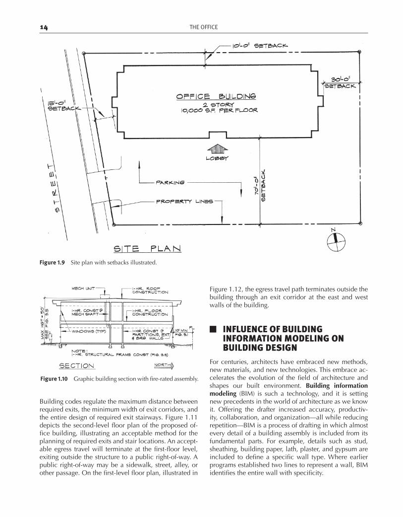
An example of code-related design requirements is provided by a site plan for a proposed two-story office building. The architect desires that all four sides of the building have windows. To satisfy this design factor, the minimum building setback from the property line will be a minimum ten feet for openings in exterior walls. Figure 1.9 depicts the proposed site plan for the two-story office building, showing property line setbacks satisfying one design requirement.
As the design program is developed, it is helpful to provide code-required assemblies in graphic form as a visual means for reviewing what is required for the vari-ous elements of the office building. An example of such a graphic aid appears in Figure 1.10. Building codes specify the wall assemblies that meet the fire-resistive requirements for the various elements of the building type selected.
Exit Requirements. Another very important part of a building code is the chapter dealing with egress requirements. This chapter sets forth the number of required exits for a specific occupancy use, based on an occupant load factor. The occupant load will depend on the use of the building. In the case of a two-story building that is designed for office use, the occupant load factor is 1 person per 100 square feet. To determine the number of exits required, the 100 square-foot occupant load factor is divided into the office floor area of 10,000 square feet. The resulting occupant factor of 100 exceeds the factor of 30, therefore requiring a minimum of two exits.
The next step in the design program is to plan the location of the required exits, required stairs, and an acceptable egress travel (the path to a required exit).
ch01.indd 13 9/30/2011 5:39:07 PM
14 THE OFFICE
Figure 1.9 Site plan with setbacks illustrated.
Figure 1.10 Graphic building section with fire-rated assembly.
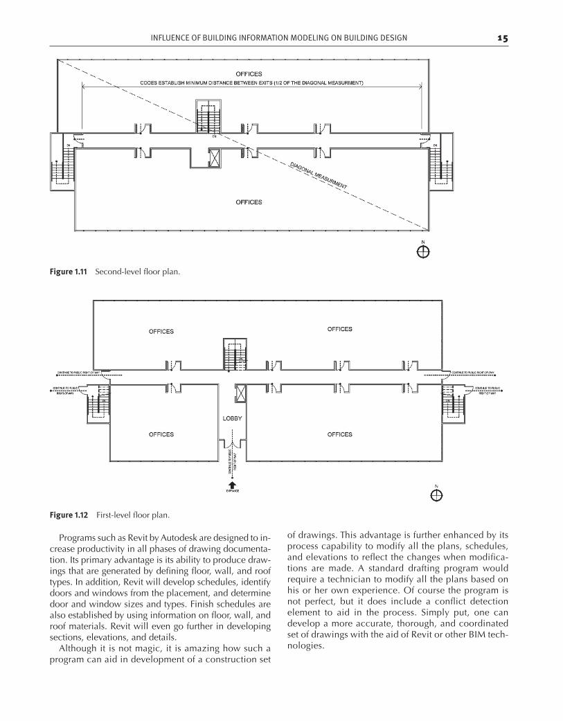
Building codes regulate the maximum distance between required exits, the minimum width of exit corridors, and the entire design of required exit stairways. Figure 1.11 depicts the second-level floor plan of the proposed of-fice building, illustrating an acceptable method for the planning of required exits and stair locations. An accept-able egress travel will terminate at the first-floor level, exiting outside the structure to a public right-of-way. A public right-of-way may be a sidewalk, street, alley, or other passage. On the first-level floor plan, illustrated in
Figure 1.12, the egress travel path terminates outside the building through an exit corridor at the east and west walls of the building.
J INFLUENCE OF BUILDING INFORMATION MODELING ON BUILDING DESIGN
For centuries, architects have embraced new methods, new materials, and new technologies. This embrace ac-celerates the evolution of the field of architecture and shapes our built environment. Building information modeling (BIM) is such a technology, and it is setting new precedents in the world of architecture as we know it. Offering the drafter increased accuracy, productiv-ity, collaboration, and organization—all while reducing repetition—BIM is a process of drafting in which almost every detail of a building assembly is included from its fundamental parts. For example, details such as stud, sheathing, building paper, lath, plaster, and gypsum are included to define a specific wall type. Where earlier programs established two lines to represent a wall, BIM identifies the entire wall with specificity.
ch01.indd 14 9/30/2011 5:39:12 PM
INFLUENCE OF BUILDING INFORMATION MODELING ON BUILDING DESIGN 15
Figure 1.11 Second-level floor plan.
Figure 1.12 First-level floor plan.
Programs such as Revit by Autodesk are designed to in-crease productivity in all phases of drawing documenta-tion. Its primary advantage is its ability to produce draw-ings that are generated by defining floor, wall, and roof types. In addition, Revit will develop schedules, identify doors and windows from the placement, and determine door and window sizes and types. Finish schedules are also established by using information on floor, wall, and roof materials. Revit will even go further in developing sections, elevations, and details.
Although it is not magic, it is amazing how such a program can aid in development of a construction set
of drawings. This advantage is further enhanced by its process capability to modify all the plans, schedules, and elevations to reflect the changes when modifica-tions are made. A standard drafting program would require a technician to modify all the plans based on his or her own experience. Of course the program is not perfect, but it does include a conflict detection element to aid in the process. Simply put, one can develop a more accurate, thorough, and coordinated set of drawings with the aid of Revit or other BIM tech-nologies.
ch01.indd 15 9/30/2011 5:39:15 PM

ch01.indd 16 9/30/2011 5:39:15 PM