Prof. Kavita Bala and Prof. Hakim Weatherspoon CS 3410 ...
46
Prof. Kavita Bala and Prof. Hakim Weatherspoon CS 3410, Spring 2014 Computer Science Cornell University See: Online P&H Chapter 6.9 (5th edition): http://booksite.elsevier.com/9780124077263/downloads/advance_contents_and_appendices/section_6.9.pdf Also, Online P&H Chapter 6.5-6 (4th edition)
Transcript of Prof. Kavita Bala and Prof. Hakim Weatherspoon CS 3410 ...
Prof. Kavita Bala and Prof. Hakim Weatherspoon
CS 3410, Spring 2014
Computer Science
Cornell UniversitySee: Online P&H Chapter 6.9 (5th edition):http://booksite.elsevier.com/9780124077263/downloads/advance_contents_and_appendices/section_6.9.pdf
Also, Online P&H Chapter 6.5-6 (4th edition)
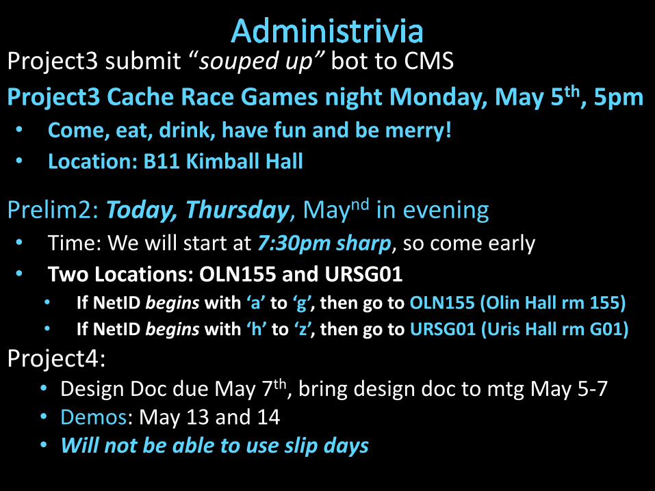
Project3 submit “souped up” bot to CMS
Project3 Cache Race Games night Monday, May 5th, 5pm• Come, eat, drink, have fun and be merry!
• Location: B11 Kimball Hall
Prelim2: Today, Thursday, Maynd in evening• Time: We will start at 7:30pm sharp, so come early
• Two Locations: OLN155 and URSG01• If NetID begins with ‘a’ to ‘g’, then go to OLN155 (Olin Hall rm 155)
• If NetID begins with ‘h’ to ‘z’, then go to URSG01 (Uris Hall rm G01)
Project4: • Design Doc due May 7th, bring design doc to mtg May 5-7• Demos: May 13 and 14• Will not be able to use slip days
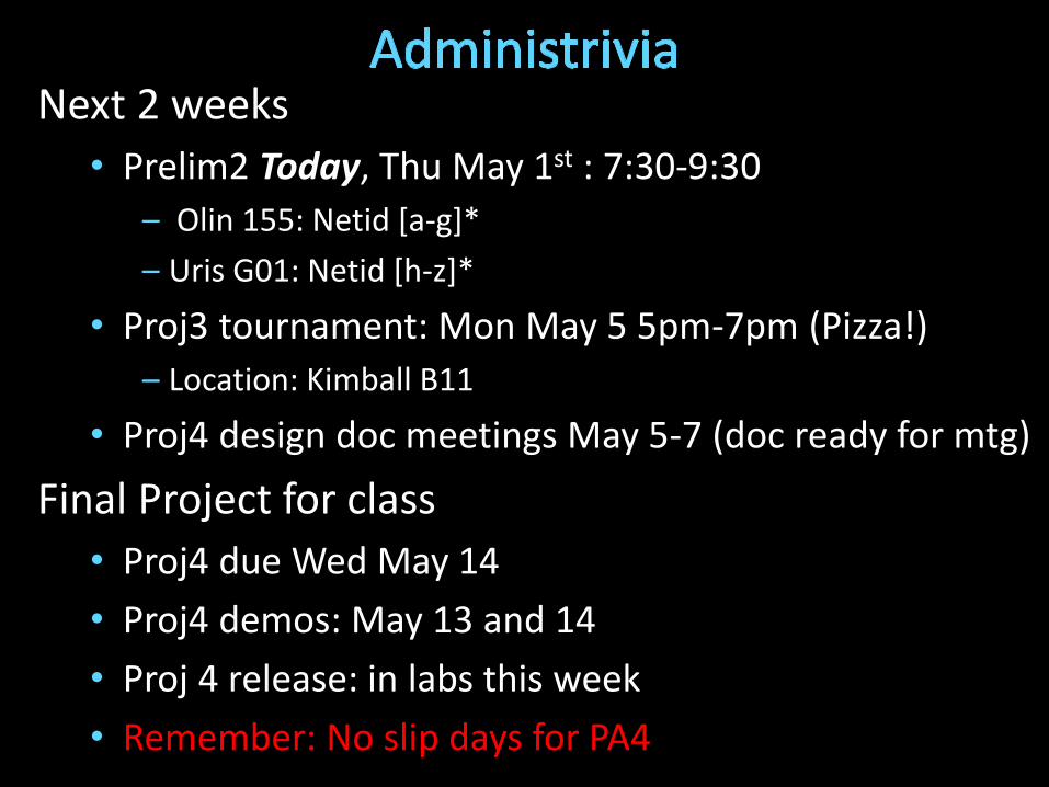
Next 2 weeks
• Prelim2 Today, Thu May 1st : 7:30-9:30
– Olin 155: Netid [a-g]*
– Uris G01: Netid [h-z]*
• Proj3 tournament: Mon May 5 5pm-7pm (Pizza!)
– Location: Kimball B11
• Proj4 design doc meetings May 5-7 (doc ready for mtg)
Final Project for class
• Proj4 due Wed May 14
• Proj4 demos: May 13 and 14
• Proj 4 release: in labs this week
• Remember: No slip days for PA4
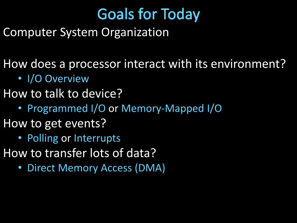
Computer System Organization
How does a processor interact with its environment?• I/O Overview
How to talk to device? • Programmed I/O or Memory-Mapped I/O
How to get events?• Polling or Interrupts
How to transfer lots of data?• Direct Memory Access (DMA)
How does a processor interact with its environment?
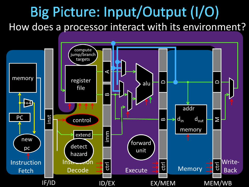
How does a processor interact with its environment?
How does a processor interact with its environment?
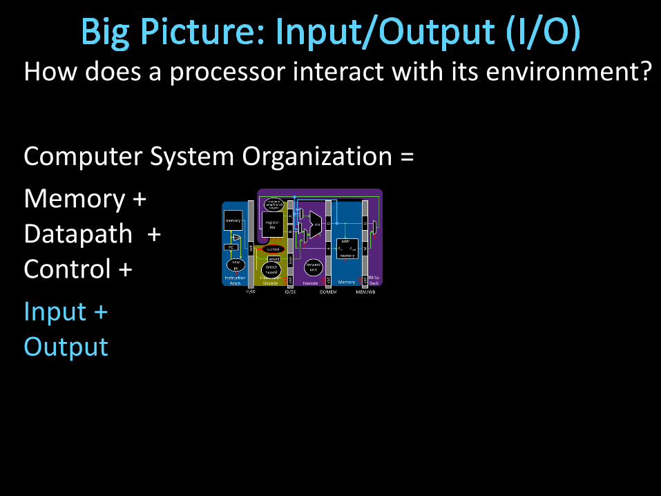
Computer System Organization =
Memory +Datapath +Control +
Input +Output

Device Behavior Partner Data Rate (b/sec)
Keyboard Input Human 100
Mouse Input Human 3.8k
Sound Input Input Machine 3M
Voice Output Output Human 264k
Sound Output Output Human 8M
Laser Printer Output Human 3.2M
Graphics Display Output Human 800M – 8G
Network/LAN Input/Output Machine 100M – 10G
Network/Wireless LAN Input/Output Machine 11 – 54M
Optical Disk Storage Machine 5 – 120M
Flash memory Storage Machine 32 – 200M
Magnetic Disk Storage Machine 800M – 3G

Replace all devices as the interconnect changes
e.g. keyboard speed == main memory speed ?!
Unified Memory and I/O Interconnect
Memory
Display Disk Keyboard Network
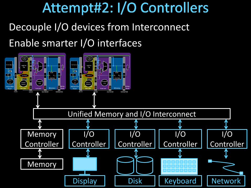
Decouple I/O devices from Interconnect
Enable smarter I/O interfaces
Core0
Cache
MemoryController
I/OController
Unified Memory and I/O Interconnect
Core1
Cache
Memory
Display
I/OController
Disk
I/OController
Keyboard
I/OController
Network

Separate high-performance processor, memory, display interconnect from lower-performance interconnect
Core0
Cache
MemoryController
I/OController
High PerformanceInterconnect
Core1
Cache
Memory
Display
I/OController
Disk
I/OController
Keyboard
I/OController
Network
Lower PerformanceLegacy Interconnect
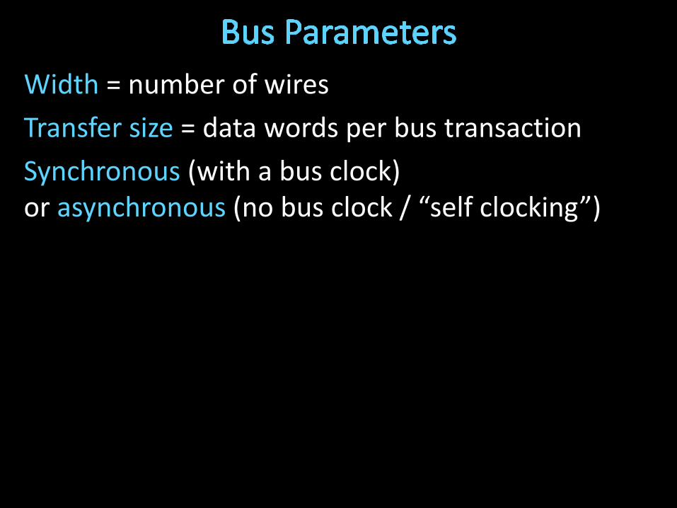
Width = number of wires
Transfer size = data words per bus transaction
Synchronous (with a bus clock)or asynchronous (no bus clock / “self clocking”)
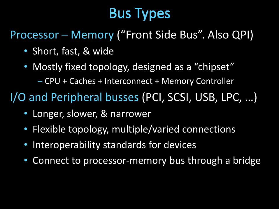
Processor – Memory (“Front Side Bus”. Also QPI)
• Short, fast, & wide
• Mostly fixed topology, designed as a “chipset”
– CPU + Caches + Interconnect + Memory Controller
I/O and Peripheral busses (PCI, SCSI, USB, LPC, …)
• Longer, slower, & narrower
• Flexible topology, multiple/varied connections
• Interoperability standards for devices
• Connect to processor-memory bus through a bridge

Separate high-performance processor, memory, display interconnect from lower-performance interconnect
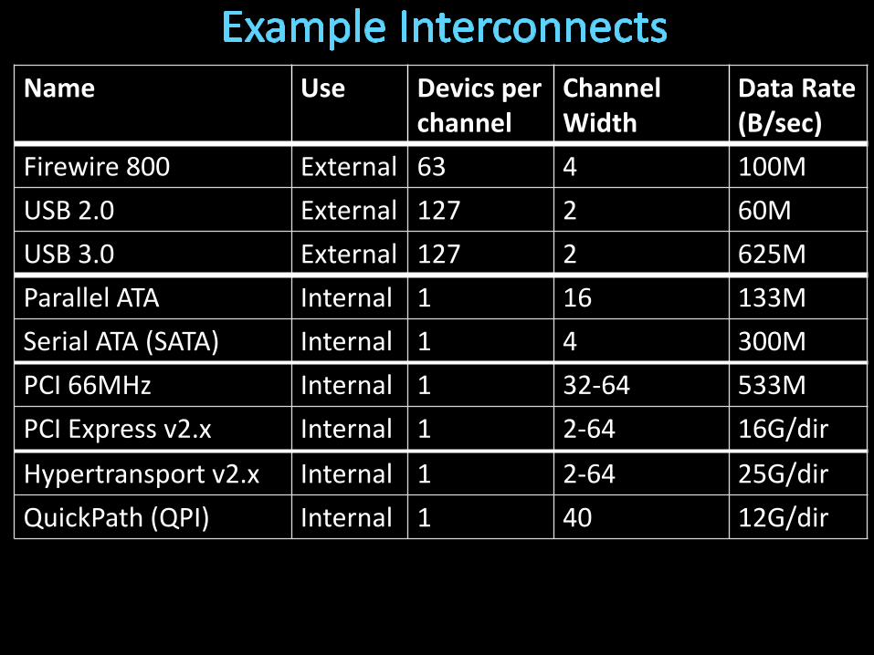
Name Use Devics per channel
Channel Width
Data Rate(B/sec)
Firewire 800 External 63 4 100M
USB 2.0 External 127 2 60M
USB 3.0 External 127 2 625M
Parallel ATA Internal 1 16 133M
Serial ATA (SATA) Internal 1 4 300M
PCI 66MHz Internal 1 32-64 533M
PCI Express v2.x Internal 1 2-64 16G/dir
Hypertransport v2.x Internal 1 2-64 25G/dir
QuickPath (QPI) Internal 1 40 12G/dir
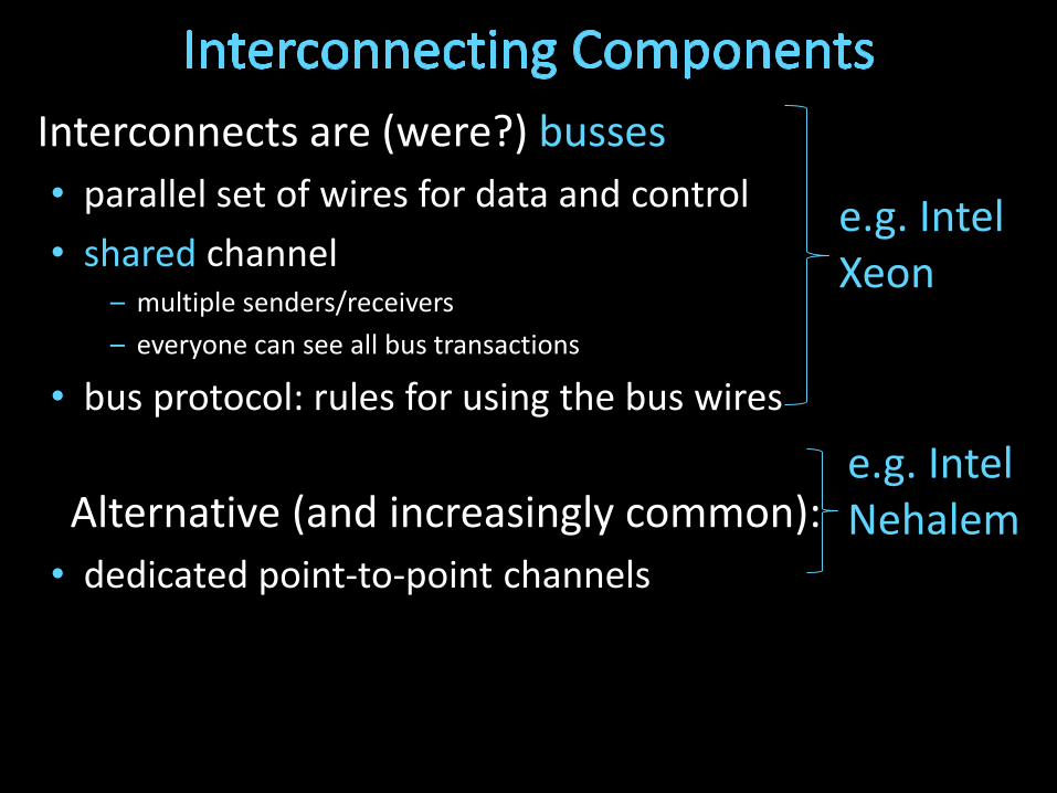
Interconnects are (were?) busses
• parallel set of wires for data and control
• shared channel– multiple senders/receivers
– everyone can see all bus transactions
• bus protocol: rules for using the bus wires
Alternative (and increasingly common):
• dedicated point-to-point channels
e.g. IntelXeon
e.g. IntelNehalem
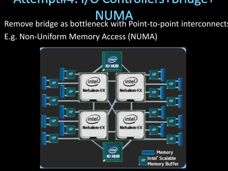
Remove bridge as bottleneck with Point-to-point interconnects
E.g. Non-Uniform Memory Access (NUMA)
Diverse I/O devices require hierarchical interconnect which is more recently transitioning to point-to-point topologies.
How does the processor interact with I/O devices?
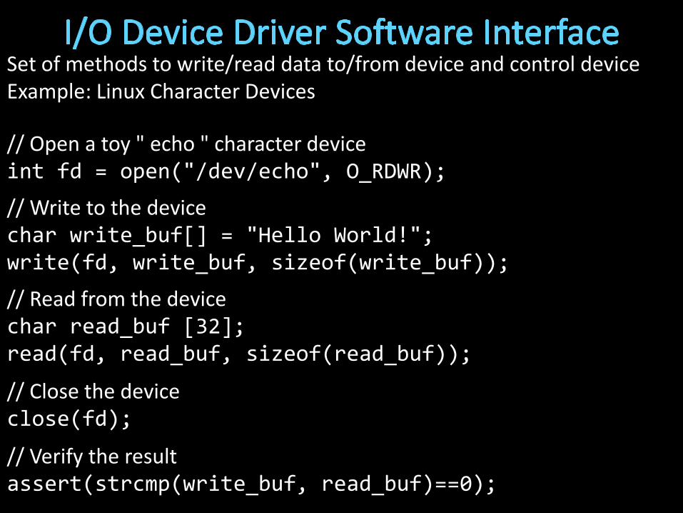
Set of methods to write/read data to/from device and control deviceExample: Linux Character Devices
// Open a toy " echo " character deviceint fd = open("/dev/echo", O_RDWR);
// Write to the devicechar write_buf[] = "Hello World!";write(fd, write_buf, sizeof(write_buf));
// Read from the devicechar read_buf [32];read(fd, read_buf, sizeof(read_buf));
// Close the deviceclose(fd);
// Verify the resultassert(strcmp(write_buf, read_buf)==0);

Typical I/O Device API
• a set of read-only or read/write registers
Command registers
• writing causes device to do something
Status registers
• reading indicates what device is doing, error codes, …
Data registers
• Write: transfer data to a device
• Read: transfer data from a device
Every device uses this API
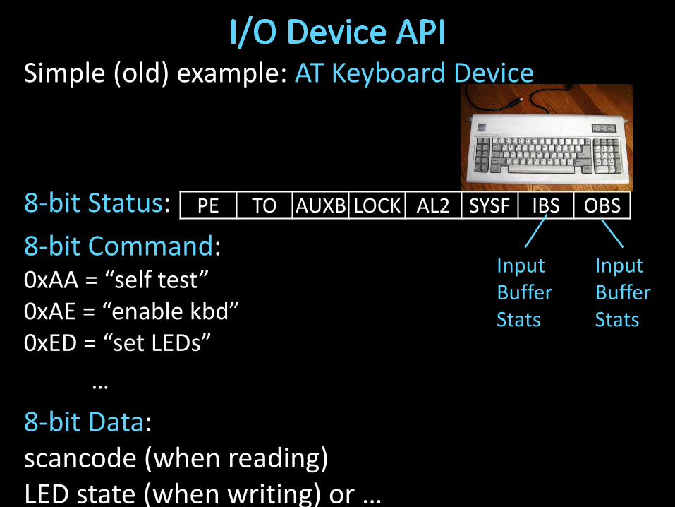
Simple (old) example: AT Keyboard Device
8-bit Status:
8-bit Command: 0xAA = “self test”0xAE = “enable kbd”0xED = “set LEDs”
…
8-bit Data: scancode (when reading) LED state (when writing) or …
PE TO AUXB LOCK AL2 SYSF IBS OBS
InputBufferStats
InputBufferStats

Q: How does program OS code talk to device?
A: special instructions to talk over special busses
Programmed I/O
• inb $a, 0x64
• outb $a, 0x60
• Specifies: device, data, direction
• Protection: only allowed in kernel mode
*x86: $a implicit; also inw, outw, inh, outh, …
Interact with cmd, status, anddata device registers directly
kbd status register
kbd data register
Kernel boundary crossinging is expensive
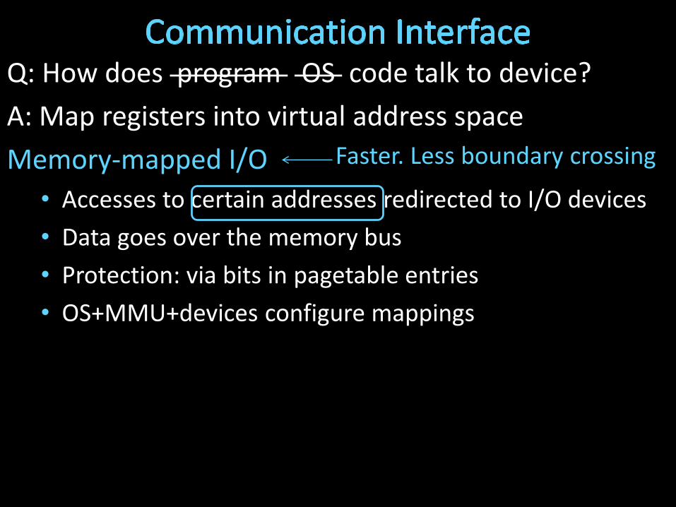
Q: How does program OS code talk to device?
A: Map registers into virtual address space
Memory-mapped I/O
• Accesses to certain addresses redirected to I/O devices
• Data goes over the memory bus
• Protection: via bits in pagetable entries
• OS+MMU+devices configure mappings
Faster. Less boundary crossing
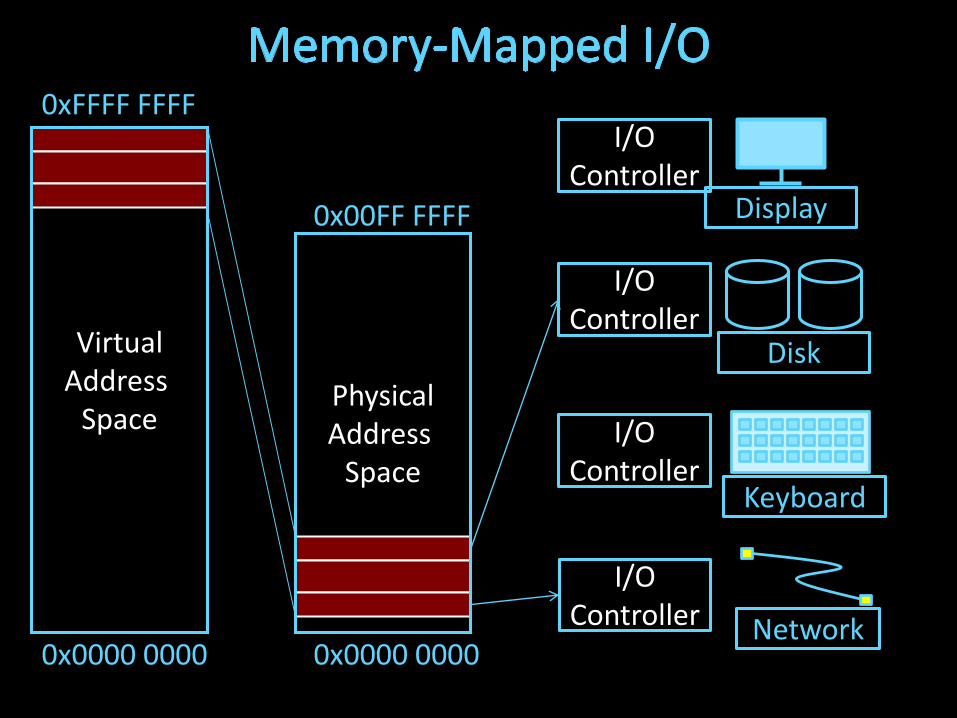
PhysicalAddress
Space
VirtualAddress
Space
0xFFFF FFFF
0x00FF FFFF
0x0000 0000 0x0000 0000
Display
Disk
Keyboard
Network
I/OController
I/OController
I/OController
I/OController
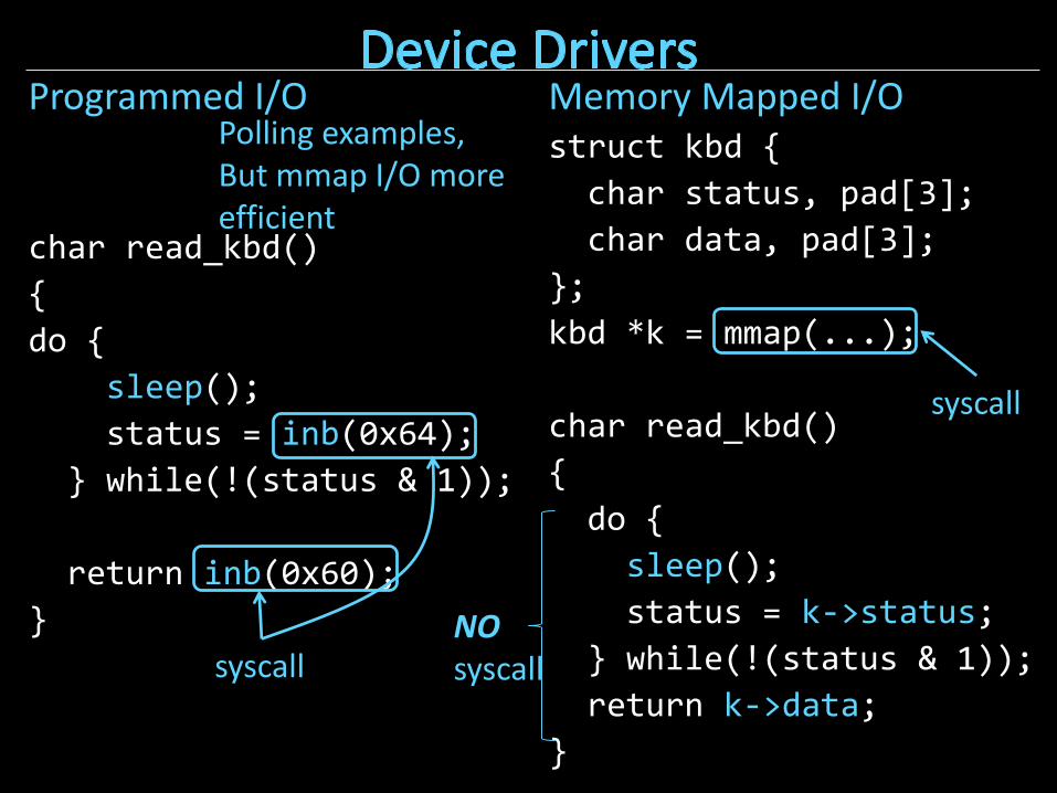
Programmed I/O
char read_kbd()
{
do {
sleep();
status = inb(0x64);
} while(!(status & 1));
return inb(0x60);
}
Memory Mapped I/Ostruct kbd {
char status, pad[3];
char data, pad[3];
};
kbd *k = mmap(...);
char read_kbd()
{
do {
sleep();
status = k->status;
} while(!(status & 1));
return k->data;
}
syscall
syscall
NOsyscall
Polling examples,But mmap I/O more efficient

Programmed I/O
• Requires special instructions
• Can require dedicated hardware interface to devices
• Protection enforced via kernel mode access to instructions
• Virtualization can be difficult
Memory-Mapped I/O
• Re-uses standard load/store instructions
• Re-uses standard memory hardware interface
• Protection enforced with normal memory protection scheme
• Virtualization enabled with normal memory virtualization scheme
Diverse I/O devices require hierarchical interconnect which is more recently transitioning to point-to-point topologies.
Memory-mapped I/O is an elegant technique to read/write device registers with standard load/stores.

How does the processor know device is ready/done?
Q: How does program learn device is ready/done?

Diverse I/O devices require hierarchical interconnect which is more recently transitioning to point-to-point topologies.
Memory-mapped I/O is an elegant technique to read/write device registers with standard load/stores.
Interrupt-based I/O avoids the wasted work in
polling-based I/O and is usually more efficient

How do we transfer a lot of data efficiently?

How to talk to device? • Programmed I/O or Memory-Mapped I/O
How to get events?• Polling or Interrupts
How to transfer lots of data?
disk->cmd = READ_4K_SECTOR;
disk->data = 12;
while (!(disk->status & 1) { }
for (i = 0..4k)
buf[i] = disk->data;
Very,Very,Expensive

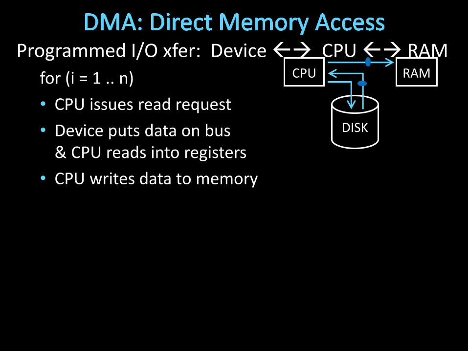
Programmed I/O xfer: Device CPU RAM
for (i = 1 .. n)
• CPU issues read request
• Device puts data on bus& CPU reads into registers
• CPU writes data to memory
• Not efficient
CPU RAM
DISK
Read from DiskWrite to MemoryEverything interrupts CPUWastes CPU

Q: How to transfer lots of data efficiently?
A: Have device access memory directly
Direct memory access (DMA)
• 1) OS provides starting address, length
• 2) controller (or device) transfers data autonomously
• 3) Interrupt on completion / error
Programmed I/O xfer: Device CPU RAM
for (i = 1 .. n)
• CPU issues read request
• Device puts data on bus& CPU reads into registers
• CPU writes data to memory
CPU RAM
DISK

Programmed I/O xfer: Device CPU RAMfor (i = 1 .. n)
• CPU issues read request
• Device puts data on bus& CPU reads into registers
• CPU writes data to memory
DMA xfer: Device RAM• CPU sets up DMA request
• for (i = 1 ... n)Device puts data on bus& RAM accepts it
• Device interrupts CPU after done
CPU RAM
DISK
CPU RAM
DISK
1) Setup 2) Transfer
3) Interrupt after done

DMA example: reading from audio (mic) input
• DMA engine on audio device… or I/O controller … or …
int dma_size = 4*PAGE_SIZE;
int *buf = alloc_dma(dma_size);
...
dev->mic_dma_baseaddr = (int)buf;
dev->mic_dma_count = dma_len;
dev->cmd = DEV_MIC_INPUT |DEV_INTERRUPT_ENABLE | DEV_DMA_ENABLE;
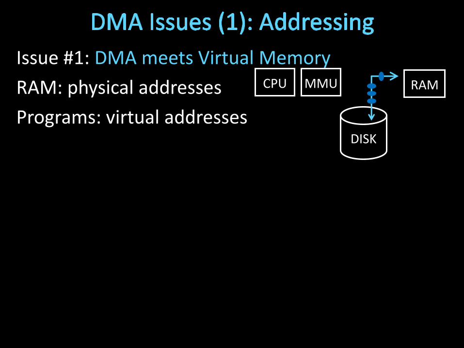
Issue #1: DMA meets Virtual Memory
RAM: physical addresses
Programs: virtual addresses
CPU RAM
DISK
MMU
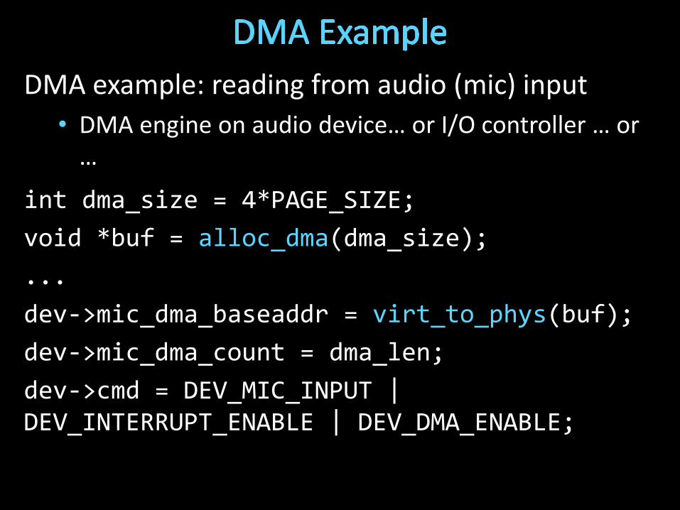
DMA example: reading from audio (mic) input
• DMA engine on audio device… or I/O controller … or …
int dma_size = 4*PAGE_SIZE;
void *buf = alloc_dma(dma_size);
...
dev->mic_dma_baseaddr = virt_to_phys(buf);
dev->mic_dma_count = dma_len;
dev->cmd = DEV_MIC_INPUT |DEV_INTERRUPT_ENABLE | DEV_DMA_ENABLE;
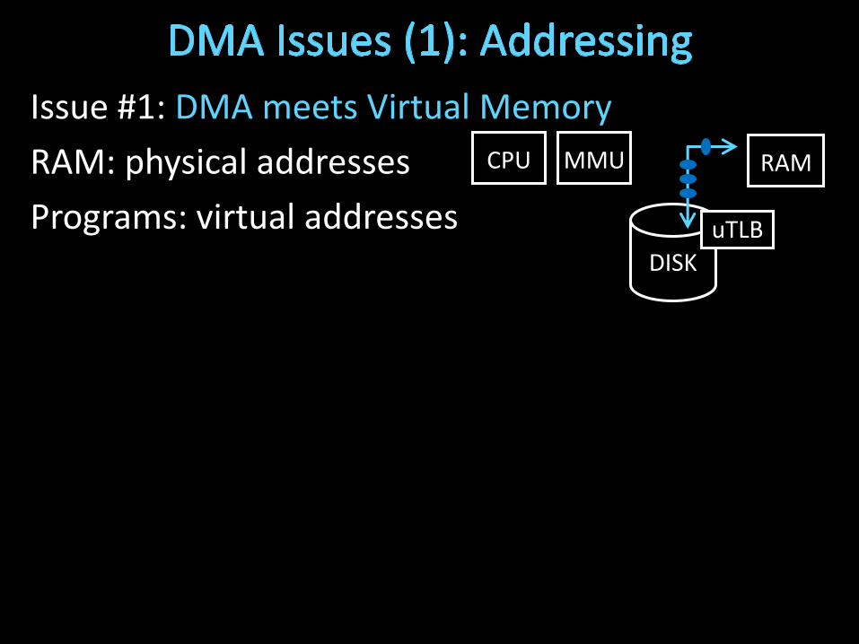
Issue #1: DMA meets Virtual Memory
RAM: physical addresses
Programs: virtual addresses
CPU RAM
DISK
MMU
uTLB

Issue #2: DMA meets Paged Virtual Memory
DMA destination page may get swapped out
CPU RAM
DISK

Issue #4: DMA meets Caching
DMA-related data couldbe cached in L1/L2
• DMA to Mem: cache is now stale
• DMA from Mem: dev gets stale data
CPU RAM
DISK
L2
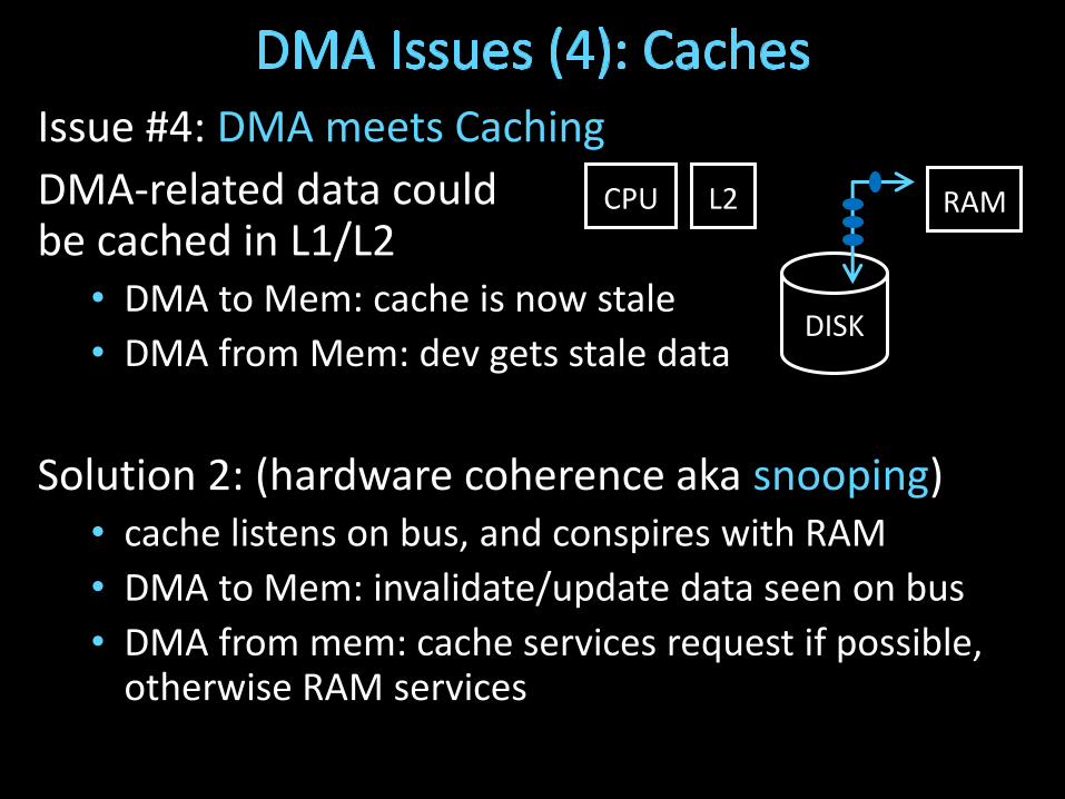
Issue #4: DMA meets Caching
DMA-related data couldbe cached in L1/L2
• DMA to Mem: cache is now stale
• DMA from Mem: dev gets stale data
Solution 2: (hardware coherence aka snooping)• cache listens on bus, and conspires with RAM
• DMA to Mem: invalidate/update data seen on bus
• DMA from mem: cache services request if possible, otherwise RAM services
CPU RAM
DISK
L2
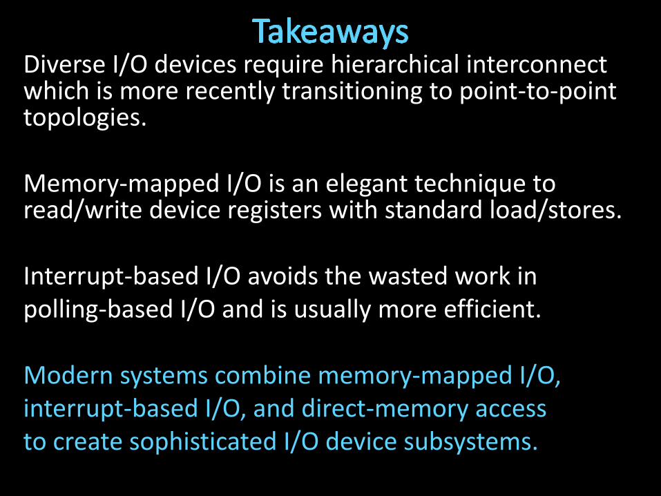
Diverse I/O devices require hierarchical interconnect which is more recently transitioning to point-to-point topologies.
Memory-mapped I/O is an elegant technique to read/write device registers with standard load/stores.
Interrupt-based I/O avoids the wasted work inpolling-based I/O and is usually more efficient.
Modern systems combine memory-mapped I/O,interrupt-based I/O, and direct-memory accessto create sophisticated I/O device subsystems.
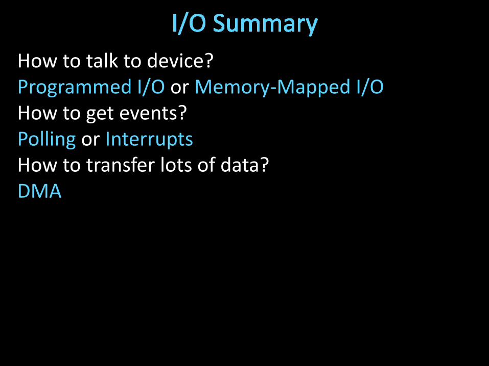
How to talk to device? Programmed I/O or Memory-Mapped I/OHow to get events?Polling or InterruptsHow to transfer lots of data?DMA


![Hakim Weatherspoon CS 3410 Computer Science Cornell ......Hakim Weatherspoon CS 3410 Computer Science Cornell University [Weatherspoon, Bala, Bracy, and Sirer] •Prelim next week](https://static.fdocuments.us/doc/165x107/600d7def4f889c31684e3fe8/hakim-weatherspoon-cs-3410-computer-science-cornell-hakim-weatherspoon-cs.jpg)

![Hakim Weatherspoon CS 3410 · 2020-01-08 · Calling Conventions Hakim Weatherspoon CS 3410. Computer Science. Cornell University [Weatherspoon, Bala, Bracy, McKee and Sirer]](https://static.fdocuments.us/doc/165x107/5f96a8e542e1ef67bd47302f/hakim-weatherspoon-cs-2020-01-08-calling-conventions-hakim-weatherspoon-cs-3410.jpg)

![Hakim Weatherspoon CS 3410Hakim Weatherspoon CS 3410. Computer Science. Cornell University [Altinbuken, Weatherspoon, Bala, Bracy, McKee, and Sirer] Announcements • P4-Buffer Overflow](https://static.fdocuments.us/doc/165x107/5e7fbc2da3de655e2e7854c1/hakim-weatherspoon-cs-hakim-weatherspoon-cs-3410-computer-science-cornell-university.jpg)