PROF. (DR.) K.S. YADAV - KopyKitab · MANUFACTURING TECHNOLOGY-I PROF. (DR.) K.S. YADAV...
16
MANUFACTURING TECHNOLOGY-I PROF. (DR.) K.S. YADAV Professionally U.K. Trained Educationist and Writer Director Satyam College of Engineering and Management, Delhi-NCR Formerly Director Subharti Institute of Technology and Engineering, Meerut, Shri Balwant Institute of Technology, Sonepat, South Point College of Engineering and Management, Sonepat, ABSS Institute of Technology, Meerut, Aravali College of Engineering and Management, and Rawal Institutions, Faridabad Vayu Education of India 2/25, Ansari Road, Darya Ganj, New Delhi-110 002 (An ISO 9001:2008 Certified Company)
Transcript of PROF. (DR.) K.S. YADAV - KopyKitab · MANUFACTURING TECHNOLOGY-I PROF. (DR.) K.S. YADAV...

MANUFACTURING
TECHNOLOGY-I
PROF. (DR.) K.S. YADAVProfessionally U.K. Trained Educationist and Writer
Director
Satyam College of Engineering and Management, Delhi-NCR
Formerly Director
Subharti Institute of Technology and Engineering, Meerut,
Shri Balwant Institute of Technology, Sonepat,
South Point College of Engineering and Management, Sonepat,
ABSS Institute of Technology, Meerut,
Aravali College of Engineering and Management, and Rawal Institutions, Faridabad
Vayu Education of India2/25, Ansari Road, Darya Ganj, New Delhi-110 002
(An ISO 9001:2008 Certified Company)
Manufacturing Technology-I
Copyright ©VAYU EDUCATION OF INDIA
ISBN: 978-93-83137-90-9
First Edition: 2013
Price: 120/-
All rights reserved. No part of this publication may be reproduced, stored in a retrieval system, or
transmitted, in any form or by any means, electronic, mechanical, photocopying, recording or
otherwise, without the prior permission of the Author and Publisher.
Printed & bound in India
Published by:
(An ISO 9001:2008 Certified Company)
VAYU EDUCATION OF INDIA2/25, Ansari Road, Darya Ganj, New Delhi-110 002
Ph.: 91-11-43526600, 41564445
Fax: 91-11-41564440
E-mail: [email protected]
Web: www.veiindia.com
1. FOUNDARY ...................................................................................................... 1
1.1 Casting Process ..................................................................................................................... 11.2 Basic Steps in Casting ........................................................................................................... 11.3 Pattern and Allowances .......................................................................................................... 1
1.3.1 Pattern ..................................................................................................................... 11.3.2 Pattern Materials ...................................................................................................... 2
1.4 Design Considerations in Pattern Making ............................................................................ 31.5 Pattern Construction ............................................................................................................. 51.6 Pattern Colours / Colouring Codes For Patterns ................................................................... 51.7 Core Prints / Types of Core Prints ........................................................................................ 61.8 Pattern Allowances ................................................................................................................. 71.9 Providing Fillets on Patterns .................................................................................................. 9
1.10 Functions of a Pattern ........................................................................................................... 91.11 Types ................................................................................................................................... 101.12 Moulding Sands and Its Desirable Properties ..................................................................... 121.13 Moulding Sand .................................................................................................................... 121.14 Classfication of Sand ........................................................................................................... 121.15 Types of Moulding Sand ...................................................................................................... 121.16 Properties of Moulding Sand .............................................................................................. 131.17 Mould making ..................................................................................................................... 141.18 Foundry Tools ...................................................................................................................... 151.19 Disadvantages of Casting .................................................................................................... 191.20 Elements of a Gating System ............................................................................................... 211.21 Die Casting ......................................................................................................................... 271.22 Advantages and Disadvantages of Die-Casting .................................................................... 281.23 Hot Chamber Die-casting Machine .................................................................................... 291.24 Cold Chamber Die-casting Machine................................................................................... 301.25 Cupola Furnace ................................................................................................................... 311.26 Charging of Cupola ............................................................................................................. 321.27 Cupola Operation ................................................................................................................ 331.28 Zones in Cupola .................................................................................................................. 341.29 Capacity of Cupola .............................................................................................................. 35
2. FORGING AND WELDING ............................................................................. 40
2.1 Forging ................................................................................................................................ 402.2 Drop Forging ....................................................................................................................... 41
CONTENTS
Manufacturing Technology-Iiv
2.3 Pneumatic Power Hammer .................................................................................................. 412.4 Forging Press ....................................................................................................................... 432.5 Power Press – Mechanical Press ......................................................................................... 432.6 Advantages of forging Process ............................................................................................. 442.7 Disadvantages of Forging Process ....................................................................................... 452.8 Introduction ........................................................................................................................ 472.9 Weldability ........................................................................................................................... 47
2.10 Concept Of Welding (Types Of Welding) ............................................................................ 472.11 Classification Of Welding Processes ................................................................................... 472.12 Forge or Smithy Welding ..................................................................................................... 482.13 RResistance Welding ........................................................................................................... 482.14 FFusion ............................................................................................................................... 522.15 Thermit Welding ................................................................................................................. 522.16 Electric Arc Welding ............................................................................................................ 53
2.16.1 ARC Welding Equipments ....................................................................................... 532.16.2 ARC Column Theory .............................................................................................. 552.16.3 Difference between A.C. and D.C. Arc Welding ...................................................... 55
2.17 Electrodes ............................................................................................................................ 562.17.1 Functions of Flux Coated on Electrodes ................................................................... 572.17.2 Welding Current ..................................................................................................... 572.17.3 Selection of Electrodes ............................................................................................. 572.17.4 Electrode Size ......................................................................................................... 582.17.5 Electrode Coverings ................................................................................................ 582.17.6 Polarity .................................................................................................................. 582.17.7 Precautions During Electric Arc Welding ................................................................. 58
2.18 Types of Welding Joints ....................................................................................................... 592.18.1 Welding Positions .................................................................................................... 612.18.2 Edge Preparation .................................................................................................... 62
2.19 Welding Defects .................................................................................................................. 632.20 Advantages And Disadvantages Of Welded Joints ............................................................... 632.21 Gas Welding ........................................................................................................................ 66
2.21.1 Working Pressure .................................................................................................... 662.22 A Assembly And Care In Use Of Equipment68
2.22.1 Fluxes ..................................................................................................................... 682.22.2 Welding Rods .......................................................................................................... 682.22.3 Types of Flame ........................................................................................................ 682.22.4 Welding Methods (Techniques) ................................................................................ 71
2.23 Soldering ............................................................................................................................. 732.24 Brazing ................................................................................................................................. 742.25 Welding of Copper .............................................................................................................. 75
Questions ................................................................................................................... 77Questions ................................................................................................................... 77Questions ................................................................................................................... 77Questions ................................................................................................................... 77
3. POWDER METALLURGY AND HEAT TREATMENT ....................................... 80
3.1 Powder Metallurgy ............................................................................................................... 803.2 The Powder Metallurgy Process .......................................................................................... 803.3 Production of Metal Powders .............................................................................................. 803.4 Main Characteristics of Metal Powders .............................................................................. 82
Contentsv
3.5 Advantages and Disadvantages of Powder Metallurgy ......................................................... 823.6 Disadvantages And Limitations ........................................................................................... 833.7 Heat Treatment .................................................................................................................... 833.8 Purpose of Heat Treatment .................................................................................................. 843.9 Principles of Heat Treatment ............................................................................................... 85
3.9.1 Stages of Heat Treatment Process ............................................................................. 853.10 Heat Treatment Processes .................................................................................................... 853.11 Annealing ............................................................................................................................. 853.12 Normalizing ......................................................................................................................... 893.13 Hardening ........................................................................................................................... 90
3.13.1 Hardenability ......................................................................................................... 923.13.2 Factors Affecting Hardenability ............................................................................... 933.13.3 Determination of Hardenability .............................................................................. 933.13.4 Hardening Methods ................................................................................................ 94
3.14 Defects In The Heat Treatment Of Steel ............................................................................. 96
4. LATHE ........................................................................................................ 98
4.1 Lathedfd .............................................................................................................................. 984.1.1 Main Parts of a Lathe ............................................................................................ 984.1.2 Lathe Speicfications ................................................................................................ 984.1.3 Working Principle of a Lathe ................................................................................ 1014.1.4 Types of L athes .................................................................................................... 102
4.1.5 Lathe Operations ............................................................................................................... 102
5. METROLOGY ............................................................................................... 110
5.1 Definitions ........................................................................................................................ 1105.2 Classification of Measuring Equipment ............................................................................ 1125.3 Technical specifications of measuring instruments ............................................................ 1135.4 Micrometers ...................................................................................................................... 114
5.4.1 Description of a Micrometer ................................................................................. 1155.4.2 Sources of Errors in Micrometers .......................................................................... 1165.4.3 Precautions in using tghe Micrometer .................................................................... 117
5.5 The Comparator................................................................................................................ 1175.6 Uses of comparators .......................................................................................................... 1185.7 Types of comparators ........................................................................................................ 1185.8 Mechancial Compartors .................................................................................................... 1195.9 Gauge ................................................................................................................................ 119
5.9.1 Classification of Gauges ........................................................................................ 1195.9.2 Description of Some Commonly Used Gauges ........................................................ 120
Questions .................................................................................................................Questions .................................................................................................................Questions .................................................................................................................Questions ................................................................................................................. 125125125125
Index ................................................................................................................ 127-128Index ................................................................................................................ 127-128Index ................................................................................................................ 127-128Index ................................................................................................................ 127-128
1.1 CASTING PROCESS
Casting is one of the oldest manufacturing processes. In this process, the metal is liquidified by heating
it in a suitable furnace. The liquid metal is poured into mould having a cavity of the shape to be formed
and allowed to solidify. The resulting solid will have the shape of the cavity in the mould. The solidified
object is called casting and the place where the castings are made is known as foundry.
Mould material is usually sand. Sometimes metal is also used to cast low temperature melting alloys.
1.2 BASIC STEPS IN CASTING
Successful casting process requires the following steps:
1. Preparation of patterns from wood, metal, plastics.
2. Select, test and prepare sand in case of sand casting.
3. Preparation of mould with the help of pattern.
4. Melt the metal/alloy to be casted.
5. Pour the molten metal/alloy in the mould and remove the casting from the mould after the
solidification of metal.
6. Clean and finish the casting.
7. Test and inspect the casting.
8. Remove the defects if any.
9. Relieve the casting stresses by heat treatment.
10. Again inspect the casting.
11. Now the casting (product) is ready for shopping.
1.3 PATTERN AND ALLOWANCES
1.3.1 Pattern
Pattern is the principal tool used during casting which may be defined as a model of any object, so
constructed that it may be used for forming an impression called mould in damp sand or other suitable
1FOUNDARY

Manufacturing Technology-I2
material. When this mould is filled with molten metal, and the metal is allowed to solidify, it forms a
reproduction of the pattern and is known as casting. The process of making a pattern is known as
pattern making.
1.3.2 Pattern Materials
The quality of casting is also influenced by the pattern materials. It is necessary to select right material
that can give the desired quality at the minimum cost. The selection of pattern materials depends on the
following factors:
1. Number of castings to be manufactured.
2. The shape and size of the casting.
3. The types of moulding process.
4. Desired accuracy and surface finish.
5. Design details of the casting.
6. Method of moulding i.e. sand moulding or machine moulding.
7. Patterns may be made by using materials such as wood, metals, plastics, plaster and wax.
1.3.2.1 Wood
Wood is the material most commonly used for making patterns for sand moulding. Wood can be easily
shaped or worked with to get patterns of desired shape and size. It is light in weight, easily available,
cheap and can be handled easily.
However, wood is easily affected by moisture, and it possesses less strength. Hence it is not suitable for
mass production. The most common types of wood are sheesham.
1.3.2.2 Metals and Alloys
Metal patterns are mostly cast from wooden patterns or machined to desired shape. Metal patters are
stronger, accurate and durable. The other advantages are its ability to withstand rough handling, high
resistance to warp, wear and abrasion.
However, metal patterns are expensive and not easily repaired. Ferrous metals get rusted. Metals are
heavier and difficult to handle. Metals can not be machined easily.
1.3.2.3 Plastics
Plastic patterns are prepared with the help of wooden patterns. Plastics are light. These are moisture
resistant and provide a smooth surface. These are also wear and corrosion resistant. Plastic patterns are
durable and do not involve any appreciable change in size and shape.
1.3.2.4 Plaster
Plaster patterns are also made with the help of wooden patterns. It can be easily worked by using wood
working tools. Intricate shapes can be made easily. Plaster has a high compressive strength. Hence the
plaster pattern is used for small and intricated castings and core boxes. Materials such as plaster of paris
or gypsum cement are commonly used for plaster patterns.
1.3.2.5 Wax
The wax pattern is made in water cooled metal mould or die. They provide a very good surface and high
accuracy. After being moulded the wax pattern is not taken out from the mould like other patterns,
rather, the mould is inverted and heated. The molten metal comes out and/or it evaporates. Thus there is
no chance of the mould cavity getting damaged while removing the pattern.
Foundary3
1.4 DESIGN CONSIDERATIONS IN PATTERN MAKING
The following points should be considered, while designing a pattern:
1. Proper allowances should be provided, whenever necessary.
2. Proper material should always be selected for the pattern.
3. The wall thicknesses and sections should be kept as uniform as possible.
4. All sharp corners and edges should be provided with suitable fillets or otherwise rounded to
enable an easy withdrawal of pattern, smooth flow of molten metal and ensure a sound casting.
5. The pattern should be given a high class surface finish as it directly effects the corresponding
finish of casting.
5. The parting line should be carefully selected, so as to allow a small portion of the pattern in the
cope as possible.
6. For large scale production of small castings, the use of match plate patterns should be encouraged.
Pattern Construction: The pattern making deals chiefly with the construction of patterns. A pattern may
be defined as a model or replica of desired casting which when moulded in sand forms an impression called
mould. The mould when filled with molten metal forms casting after solidification of the metal. The quality and
accuracy of casting depends upon the pattern making.
Types of Pattern: The type of pattern selected for a particular casting depends upon the following conditions:
1. The shape and size of casting.
2. The number of castings required, and
3. The method of moulding employed.
The Common Types of patterns are:
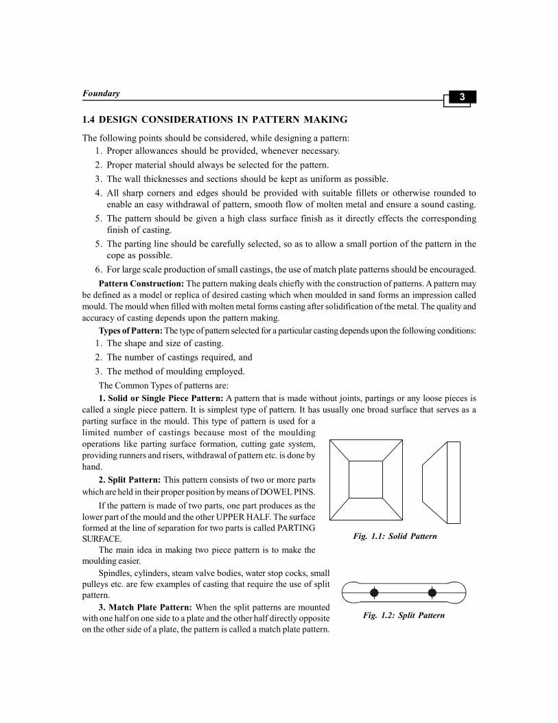
1. Solid or Single Piece Pattern: A pattern that is made without joints, partings or any loose pieces is
called a single piece pattern. It is simplest type of pattern. It has usually one broad surface that serves as a
parting surface in the mould. This type of pattern is used for a
limited number of castings because most of the moulding
operations like parting surface formation, cutting gate system,
providing runners and risers, withdrawal of pattern etc. is done by
hand.
2. Split Pattern: This pattern consists of two or more parts
which are held in their proper position by means of DOWEL PINS.
If the pattern is made of two parts, one part produces as the
lower part of the mould and the other UPPER HALF. The surface
formed at the line of separation for two parts is called PARTING
SURFACE.
The main idea in making two piece pattern is to make the
moulding easier.
Spindles, cylinders, steam valve bodies, water stop cocks, small
pulleys etc. are few examples of casting that require the use of split
pattern.
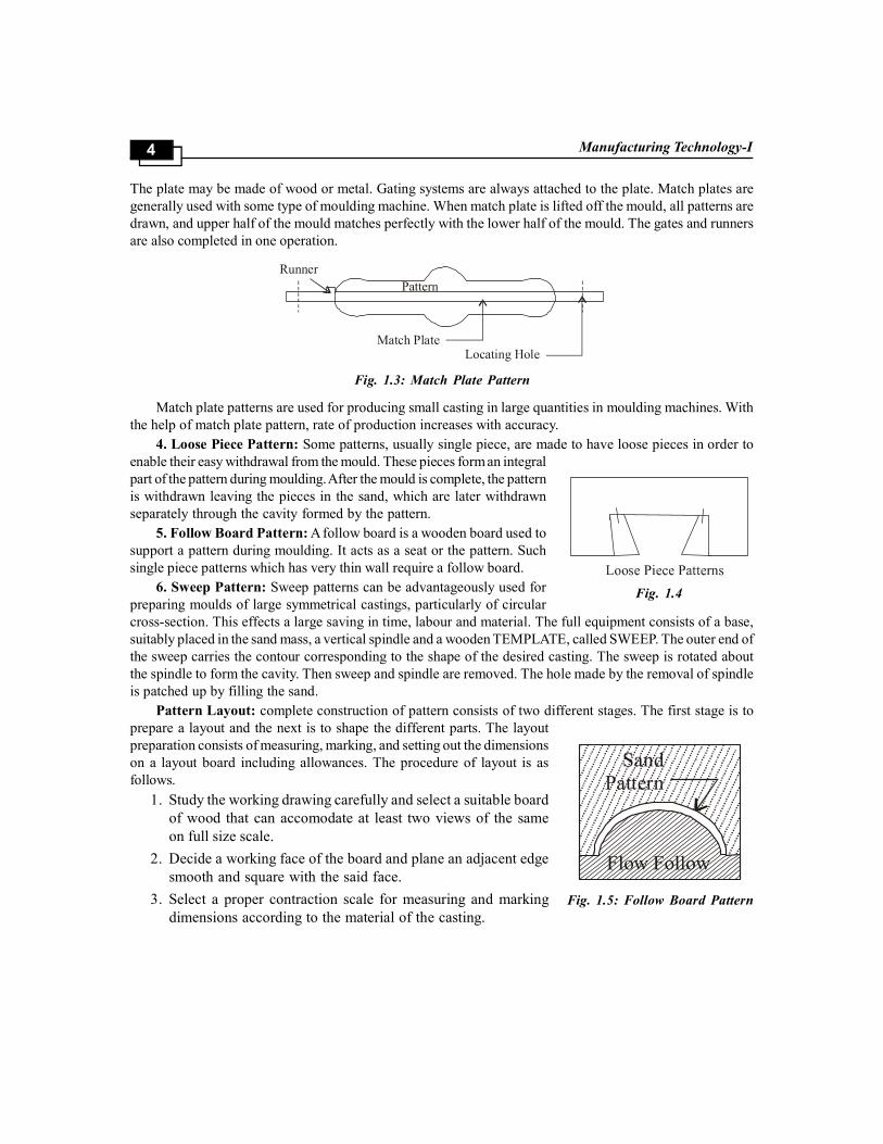
3. Match Plate Pattern: When the split patterns are mounted
with one half on one side to a plate and the other half directly opposite
on the other side of a plate, the pattern is called a match plate pattern.
Fig. 1.1: Solid Pattern
Fig. 1.2: Split Pattern
Manufacturing Technology-I4
Fig. 1.5: Follow Board Pattern
Fig. 1.4
The plate may be made of wood or metal. Gating systems are always attached to the plate. Match plates are
generally used with some type of moulding machine. When match plate is lifted off the mould, all patterns are
drawn, and upper half of the mould matches perfectly with the lower half of the mould. The gates and runners
are also completed in one operation.
Fig. 1.3: Match Plate Pattern
Match plate patterns are used for producing small casting in large quantities in moulding machines. With
the help of match plate pattern, rate of production increases with accuracy.
4. Loose Piece Pattern: Some patterns, usually single piece, are made to have loose pieces in order to
enable their easy withdrawal from the mould. These pieces form an integral
part of the pattern during moulding. After the mould is complete, the pattern
is withdrawn leaving the pieces in the sand, which are later withdrawn
separately through the cavity formed by the pattern.
5. Follow Board Pattern: A follow board is a wooden board used to
support a pattern during moulding. It acts as a seat or the pattern. Such
single piece patterns which has very thin wall require a follow board.
6. Sweep Pattern: Sweep patterns can be advantageously used for
preparing moulds of large symmetrical castings, particularly of circular
cross-section. This effects a large saving in time, labour and material. The full equipment consists of a base,
suitably placed in the sand mass, a vertical spindle and a wooden TEMPLATE, called SWEEP. The outer end of
the sweep carries the contour corresponding to the shape of the desired casting. The sweep is rotated about
the spindle to form the cavity. Then sweep and spindle are removed. The hole made by the removal of spindle
is patched up by filling the sand.
Pattern Layout: complete construction of pattern consists of two different stages. The first stage is to
prepare a layout and the next is to shape the different parts. The layout
preparation consists of measuring, marking, and setting out the dimensions
on a layout board including allowances. The procedure of layout is as
follows.
1. Study the working drawing carefully and select a suitable board
of wood that can accomodate at least two views of the same
on full size scale.
2. Decide a working face of the board and plane an adjacent edge
smooth and square with the said face.
3. Select a proper contraction scale for measuring and marking
dimensions according to the material of the casting.

Foundary5
Fig. 1.6: Sweep Pattern
4. Prepare the layout nearly with the help of various measuring and marking tools properly specifying
the locations of core prints and machined surfaces.
6. Check it finally before starting construction.
1.5 PATTERN CONSTRUCTION
After preparing the layout, proceed for pattern construction as follows:
1. Study the layout and decide the location of parting lines.
2. From the layout, try to visualise the shape of the pattern and determine the number of separate
pieces to be made and the process to be employed for making them.
3. Start construction of pattern from the main part of its body. Try to keep the direction of wood
grains along the length of pattern to ensure due accuracy and strength.
4. Cut and shape different parts providing adequate draft on them.
5. Check all the prepared parts finally by placing them over the prepared layout.
6. Assemble different parts in position by glueing or by means of dowels as the case may be.
7. Check the relative locations of all the assembled parts on the pattern.
8. Finally, check whole of the completed pattern for accuracy.
9. Finish all the rough surfaces by standing and give a thin coating of shellac varnish.
10. Fit the wax or leather fillets wherever necessary. Wooden fillets, of course, should be fitted
before sanding the finishing.
11. Sand the pattern surface once again and give final coats of shellac.
12. Colour different parts of surface with specific colours mixed in shellac or by painting.
1.6 PATTERN COLOURS / COLOURING CODES FOR PATTERNS
There is not universally accepted standard for representation of different types of surfaces by different
colours. The practice varies with different countries and sometimes with different manufacturers also
in the same country. The following practice will serve as useful a guide both for patterns and core
boxes:
1. Red—Surface to be machined.
Manufacturing Technology-I6
2. Black—Surface to be left unmachined.
3. Yellow—Core Prints.
4. Red stripes on yellow base—Seats for loose pieces.
5. Black stripes on yellow base—Stop offs.
6. Clear or No colour—Parting surface.
1.7 CORE PRINTS / TYPES OF CORE PRINTS
When a casting is required to have a hole, through or blind, a core is used in the mould to produce the
same. This core has to be properly seated in the mould on formed impressions in the sand. To form
these impressions, extra projections are added on the pattern surface at proper places. These projections
are known as core prints. Core prints are of the following types:
1. Horizontal Core print: It produces seats for horizontal core in the mould.
2. Vertical Core print: It produces seats to support a vertical core in the mould.
3. Balanced Core print: It produces a single seat on one side of the mould and the core remains
partly in this formed seat and partly in the mould cavity, the two portions balancing each other.
The hanging portion of the core may be supported on chaplets.
4. Cover Core print: It forms seat to support a cover core.
5. Wing Core print: It is used to form a seat for a wing core.
Core Boxes
Core boxes are used for making cores. They are either made single or in two parts. Their classification is,
generally, according to the shape of the core or the method of making the core. The common types of core
boxes are the following:
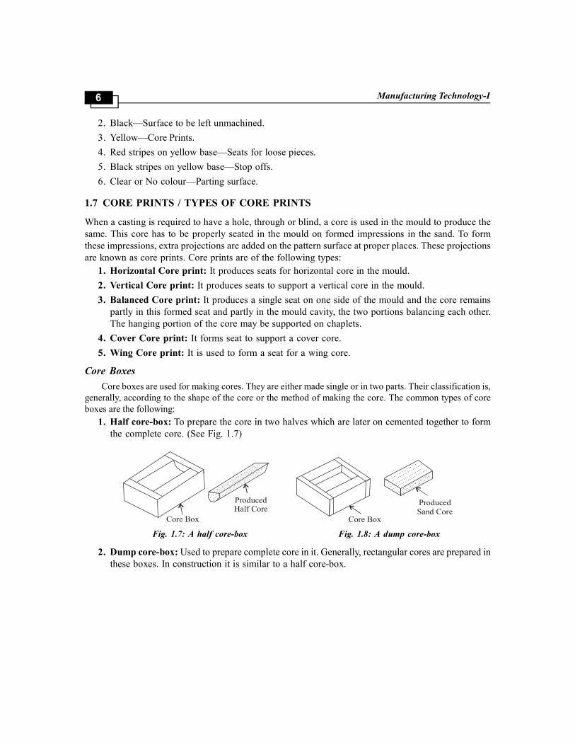
1. Half core-box: To prepare the core in two halves which are later on cemented together to form
the complete core. (See Fig. 1.7)
Fig. 1.7: A half core-box Fig. 1.8: A dump core-box
2. Dump core-box: Used to prepare complete core in it. Generally, rectangular cores are prepared in
these boxes. In construction it is similar to a half core-box.

Foundary7
Fig. 1.9: Split core-box
3. Split core-box: It is made in two parts, which can be joined together by means of dowels to form
the complete cavity for making the core.
4. Strickle type core-box: It is used to form cores of irregular or un-symmetrical shapes, as
shown in Fig. 1.10.
Fig. 1.10: Strickle type core-box Fig. 1.11: Loose piece core-box
5. Loose piece core-box: It is used to prepare, in the same core box, the two halves of a core of
which the halves are not identical in shape and size.
6. Right and left hand core boxes: They are used to prepare, one half each of the type of core
described at S. No. 5 above.
1.8 PATTERN ALLOWANCES
A pattern is always made larger than the required size of the casting to allow for various factors, such as
shrinkage, machining, distortion and rapping etc. The following allowances are provided in a pattern:
1. Shrinkage Allowance: Most of the metals used in casting work contract during cooling from pouring
temperature to room temperature.
The amount of contraction varies with different metals and, therefore, their corresponding allowances
also differ. The prominent factors, which influence the metal contraction are the following:
Manufacturing Technology-I8
1. Pouring temperature of molten metal.
2. Design and dimensions of the casting.
3. Type of mould material.
4. Moulding method.
5. Mould resistance to shrinkage of metal.
6. The metal of which the casting is to be made.
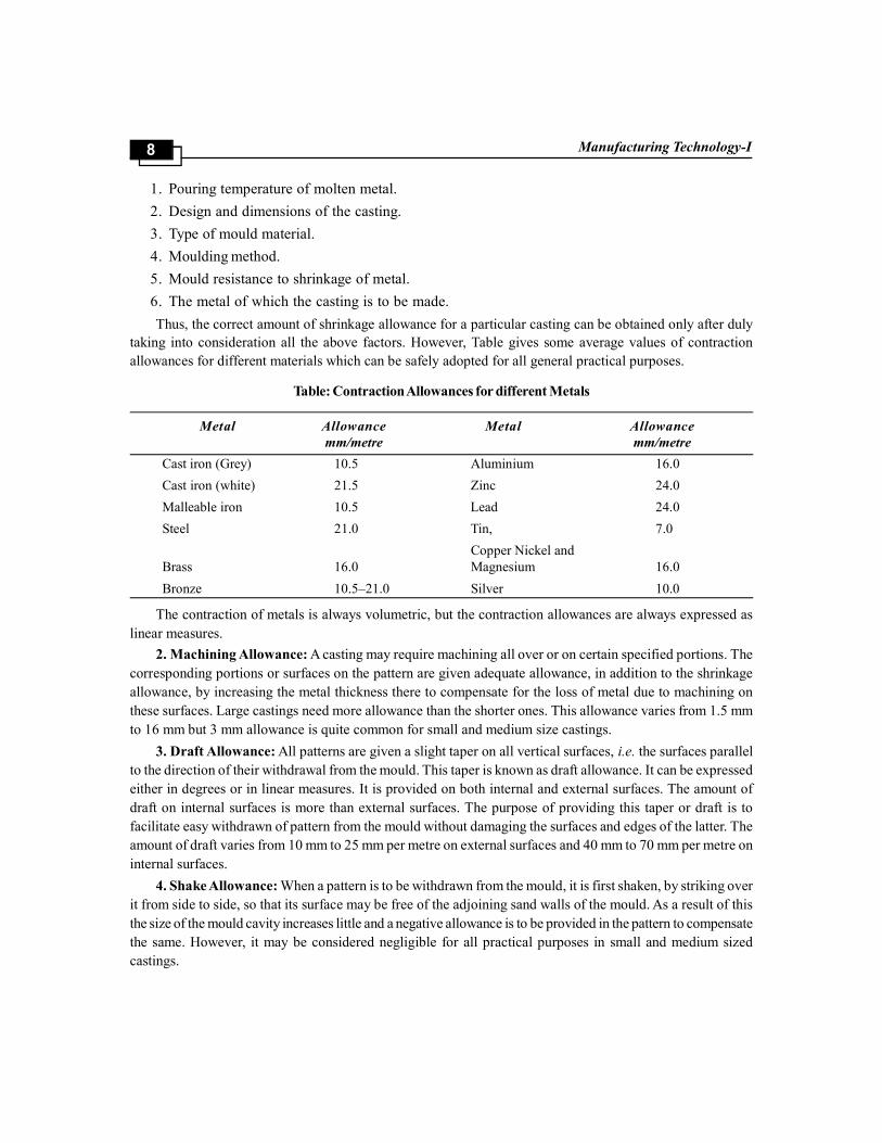
Thus, the correct amount of shrinkage allowance for a particular casting can be obtained only after duly
taking into consideration all the above factors. However, Table gives some average values of contraction
allowances for different materials which can be safely adopted for all general practical purposes.
Table: Contraction Allowances for different Metals
Metal Allowance Metal Allowance
mm/metre mm/metre
Cast iron (Grey) 10.5 Aluminium 16.0
Cast iron (white) 21.5 Zinc 24.0
Malleable iron 10.5 Lead 24.0
Steel 21.0 Tin, 7.0
Copper Nickel and
Brass 16.0 Magnesium 16.0
Bronze 10.5–21.0 Silver 10.0
The contraction of metals is always volumetric, but the contraction allowances are always expressed as
linear measures.
2. Machining Allowance: A casting may require machining all over or on certain specified portions. The
corresponding portions or surfaces on the pattern are given adequate allowance, in addition to the shrinkage
allowance, by increasing the metal thickness there to compensate for the loss of metal due to machining on
these surfaces. Large castings need more allowance than the shorter ones. This allowance varies from 1.5 mm
to 16 mm but 3 mm allowance is quite common for small and medium size castings.
3. Draft Allowance: All patterns are given a slight taper on all vertical surfaces, i.e. the surfaces parallel
to the direction of their withdrawal from the mould. This taper is known as draft allowance. It can be expressed
either in degrees or in linear measures. It is provided on both internal and external surfaces. The amount of
draft on internal surfaces is more than external surfaces. The purpose of providing this taper or draft is to
facilitate easy withdrawn of pattern from the mould without damaging the surfaces and edges of the latter. The
amount of draft varies from 10 mm to 25 mm per metre on external surfaces and 40 mm to 70 mm per metre on
internal surfaces.
4. Shake Allowance: When a pattern is to be withdrawn from the mould, it is first shaken, by striking over
it from side to side, so that its surface may be free of the adjoining sand walls of the mould. As a result of this
the size of the mould cavity increases little and a negative allowance is to be provided in the pattern to compensate
the same. However, it may be considered negligible for all practical purposes in small and medium sized
castings.

Foundary9
5. Distortion Allowance: The castings which have an irregular shape and some such design that the
contraction is not uniform throughout will distort during cooling on account of the setting up of thermal
stresses in them. Such an effect can be easily seen in some dome shaped or ‘U’ shaped castings. To eliminate
this defect an opposite distortion is provided in the pattern, so that the effect is neutralised and the correct
casting is obtained.
6. Mould-wall Movement Allowance: Movement of mould walls in sand moulds takes place on account of
the excessive heat and the static pressure exerted on the surface layer of sand which comes in contact with the
molten metal. Graphitisation is another cause of mould wall movement in case of ferrous castings. This movement
of mould, obviously, affects the ultimate size of the castings and needs of be compensated by providing
corresponding allowance in the pattern and by controlling the density and temperature of the molten and
composition of the moulding sand.
1.9 PROVIDING FILLETS ON PATTERNS
If sharpe edges are allowed to remain on the pattern, where adjoining surfaces meet, they will produce
corresponding sharp edges in the mould cavity. They will either be washed away during pouring or
weaken the casting due to concentration of stresses there. These sharp edges should, therefore, be
eliminated in patterns by providing fillets on these junction points. For this, previously prepared fillets of
wood, metal, wax or plastic may be used. Sharp edges can also be slightly rounded by filing them. If
sharp edges are at all required on the finished component, these fillets may be removed by machining.
1.10 FUNCTIONS OF A PATTERN
The main functions of a pattern are:
1. To produce the mould cavity of appropriate shape and size in which the molten metal can be
poured to obtain desired casting.
2. To produce seats for cores in the mould in which cores can be placed to produce cavity in the
casting. These seats in the mould are called core prints.
Core: A core can be defined as a body of sand, generally prepared separately in a core
box, which is used to form a cavity of desired shape and size in a casting.
Steps Involved:
1. Core Sand Preparation
2. Making the cores
3. Baking the cores
4. Finishing of cores
5. Setting the cores
1. Core Sand Preparation: In Small foundries the core sand mixtures are still prepared through hand
operations. But these operations do not facilitate a homogeneous and efficient mixing. To achieve this, mechanical
means are adopted. The common means include the use of either roller mills or core sand mixers. Two varieties
of core sand mixers are in common use. They are (I) Vertical revolving arm type. (II) Horizontal paddle type.
2. Making the cores: (I) Small cores can be made manually in hand rammed core boxes.
(II) Cores on mass scale are rapidly produced on a variety of core-making machines, to name a few:

Manufacturing Technology-I10
(a) Jolt machine (b) Core roll-over machine
(c) Sand slinger (d) Core extrusion machine
(e) Core blower (f) Shell core machine
Baking the cores: After the green sand cores are adequately supported on the core plate or core drier, they
are sent to ovens for Baking.
Core baking develops the proporties of the organic binders. Core-baking drives off moisture from the
cores, oxidizes the oil and polymerizes the binder, cores are baked up at 650o F.
Finishing of cores: Baked cores are finished before they can be set in the mould. Core finishing consists
of. (a) Cleaning (b) Sizing (c) Core Assembly.
Setting the cores: core-setting means placing cores in the mold. In order to obtain correct cavities in the
castings, the cores should be accurately positioned in the moulds.
Core - Assembly: Core assembling means joining together by pasting, leading or bolting two or more
component parts of the core before the core can be set in the mould. Core paste can be applied over the core
with the help of finger, by brushing or dipping.
Large core parts are assembled by nuts and bolts. Nuts and bolts are of course covered with mud after
joining the core parts.
Core Prints: castings are often required to have holes and recesses of various sizes and shapes. These
impressions are made by using sand cores which are separtely made in boxes known as core boxes. For
supporting the cores in the mould cavity, an impression in the form of a recess is made in the mould with the
help of a projection suitably placed on the pattern. This projection on the pattern is known as the core print.
A core print is, therefore, an added projection on the pattern, and it forms a seat which is used to support
and locate the core in the mould. The core prints are provided so that the cores are securely and correctly
positioned in the mould cavity. The design of core prints is such as to take care of the weight of the core before
pouring and the upward pressare of the molten metal after pouring. The core prints should also ensure that the
core is not shifted during the entry of the metal into the mould cavity.
1.11 TYPES
1. Horizontal core print: This is laid horizontally in the mould (Fig. 1)
Fig. 1.12
Manufacturing Technology-I By Dr. K.S.Yadav
Publisher : Vayu Education ISBN : 9789383137909 Author : Dr. K.S. Yadav
Type the URL : http://www.kopykitab.com/product/3215
Get this eBook


![Design Portfolio [Taloza, K.S.]](https://static.fdocuments.us/doc/165x107/55c7e485bb61ebc56e8b4728/design-portfolio-taloza-ks.jpg)