Produktkatalog SC Flex ENG neu - IBS Technics€¦ · In the case of wall-mounted penstocks subject...
29
Product Catalogue Stainless Steel Penstocks Series SC-FLEX
Transcript of Produktkatalog SC Flex ENG neu - IBS Technics€¦ · In the case of wall-mounted penstocks subject...

Product Catalogue
Stainless Steel Penstocks
Series SC-FLEX

IBS Product Catalogue
SC-FLEX
V03/14 © (IBS Technics GmbH, Gemeindewald 6, 86672 Thierhaupten, Germany, Phone: 08271-8176-0) Page 2 of 29
Contents
1 General............................................................................................................... 4
1.1 Design ................................................................................................................. 4
1.2 Leakage .............................................................................................................. 4
1.3 Definition of Terms .............................................................................................. 5
1.4 Sizes ................................................................................................................... 6
1.5 On- / Off-Seating water head ............................................................................... 7
1.6 Seal and Guide Design ....................................................................................... 8
1.7 Frame Bracket Selection ..................................................................................... 8
2 Materials ...........................................................................................................11
3 Frame Mounting Types ....................................................................................12
3.1 General ..............................................................................................................12
3.2 Invert Frame .......................................................................................................12
3.3 Side Frame ........................................................................................................12
3.4 Soffit Frame .......................................................................................................13
3.5 Yoke ...................................................................................................................14
3.5.1 Design for DN 150 to DN 500 .............................................................................14
3.5.2 Design for DN 600 to DN 1200 ...........................................................................14
4 Operation Types ...............................................................................................15
4.1 Manual Operation ...............................................................................................15
4.1.1 Cap Top .............................................................................................................15
4.1.2 Handwheel .........................................................................................................15
4.1.3 Handwheel d = 315mm with Bevel Gearbox GK 10.2 or GK 14.2 .....................15
4.2 Electric Multi-turn Actuator .................................................................................15
4.3 Cylinder Pistons .................................................................................................16
4.3.1 Pneumatic Actuated ...........................................................................................16
4.3.2 Hydraulic Actuated .............................................................................................16
4.4 Standard Operation Specifications .....................................................................16
4.4.1 Manual Operation with Handwheel .....................................................................17
4.4.2 Electric Actuators ...............................................................................................18
5 Accessories ......................................................................................................19
5.1 Pedestal .............................................................................................................19
5.1.1 Floor Mounted – F10 ..........................................................................................19
IBS Product Catalogue
SC-FLEX
V03/14 © (IBS Technics GmbH, Gemeindewald 6, 86672 Thierhaupten, Germany, Phone: 08271-8176-0) Page 3 of 29
5.1.2 Wall Mounted – T20-F10 ....................................................................................19
5.2 Brackets .............................................................................................................19
5.2.1 Floor Bracket ......................................................................................................19
5.2.2 Wall Bracket .......................................................................................................19
5.2.3 Spindle Guide Bracket D32 .............................................................................19
5.2.4 Frame Bracket....................................................................................................19
5.2.5 Channel Side Wall Bracket GW ..........................................................................20
5.3 Spindle / Spindle Extension and Spindle Nut ......................................................20
5.3.1 Spindle Nut Rg 7 - 40 ......................................................................................20
5.3.2 Spindle Nut Rg 7 - 60 ......................................................................................20
5.4 Mounting Conditions / Materials .........................................................................20
5.4.1 General Information ...........................................................................................20
5.4.2 Mounting Surface ...............................................................................................20
5.4.3 Evenness / Tolerances .......................................................................................21
5.4.4 Anchorage ..........................................................................................................21
5.4.5 Sealing to Concrete Surface...............................................................................22
6 Model Types .....................................................................................................22
6.1 General ..............................................................................................................22
6.2 Sizes for RPS – FX M1-WM-Wb-OF/ON: Flex Penstock 4-sided sealed, self contained with non-rising Spindle, wall mounted ................................................23
6.3 Sizes for RSG – FX M2-CS-F: Flex Channel Penstock 3-sided sealed, self contained with rising Spindle, channel side wall mounted ..................................24
6.4 Sizes for RSG – FX M2-CR-R: Flex Channel Penstock 3-sided sealed, self contained with rising Spindle, in rebate ..............................................................25
6.5 Sizes for RPS – FX M3-WM-Wb-OF/ON: Flex Penstock 4-sided sealed, open with non-rising Spindle, wall mounted ................................................................26
6.6 Sizes for RPS – FX M4-WM-Wb-OF/ON: Flex Penstock 4-sided sealed, open with rising Spindle, wall mounted .......................................................................27
6.7 Sizes for RWG – FX M1-WM-Wb-OF/ON: Flex Weir Penstock 3-sided sealed, self contained with non-rising Spindle, wall mounted ..........................................28

IBS Product Catalogue
SC-FLEX
V03/14 © (IBS Technics GmbH, Gemeindewald 6, 86672 Thierhaupten, Germany, Phone: 08271-8176-0) Page 4 of 29
1 General
1.1 Design
The IBS FLEX series for the four-sided sealed penstock (RPS), the three-sided sealed channel penstock (RSG) and the three-sided sealed weir penstock (RWG) are designed as modular constructions. This modular design permits the adaptation of the FLEX series to numerous installation situations occurring in everyday construction work. At the same time, the use of standardised interchangeable components ensures the shortest possible production times, maximum process reliability and consistently high quality. Due to innovative production methods and modern machine technology, precise components are manufactured according to the drawings. The interaction of guides, axis alignments, sealing surfaces and load-bearing components is ensured through automated, routine procedural processes. Most of the quality criteria such as geometry, fit accuracy, ease of movement, stability etc. are therefore consistently fulfilled within narrow tolerance limits.
1.2 Leakage
Our penstocks meet internationally recognized standards including BS 7775, AWWA and DIN 19569.

IBS Product Catalogue
SC-FLEX
V03/14 © (IBS Technics GmbH, Gemeindewald 6, 86672 Thierhaupten, Germany, Phone: 08271-8176-0) Page 5 of 29
1.3 Definition of Terms
1. Side Frame 2. Door 3. Invert Frame 4. Yoke 5. Stem Nut 6. Spindle 7. Spindle
Extension 8. Spindle Guide
Bracket 9. Frame Bracket 10. Pedestal 11. Actuator (Electric,
Handwheel, Cap Top)
12. Wall Bracket 13. Invert Seal 14. Double Lip Seal 15. Door Guide

IBS Product Catalogue
SC-FLEX
V03/14 © (IBS Technics GmbH, Gemeindewald 6, 86672 Thierhaupten, Germany, Phone: 08271-8176-0) Page 6 of 29
1.4 Sizes The designs presented in this catalogue span channel widths from 200mm to 1,200 mm with varying heights. Both square and circular cross-sections are uniformly designated as DN. The aperture encompassed by a DN side frame always has a square geometry. Rectangular cross-sections are designated as RQ. The standard sizes are graded from DN 150 to DN 400 in 50mm increments. From DN 400 to DN 1200, the increment pattern is 100mm. For example, a DN 1000 design has a clear frame aperture of 1050mm. With a planned opening width of 1000mm, 25mm tolerance per side would be available for a wall-mounted installation situation. The outer frame width of a DN 1000 design has a total dimension (without frame fixing bracket), of 1210mm. This door design could therefore be installed into an existing channel with a width of, for example, 1,250mm side wall-mounted (=without rebate). For channel installation into a rebate, this would fit into a channel width of 1050mm.
DN 1000 Wall Mounted - Opening Width 1000mm
DN 1000 Channel Side Wall Mounted - Channel Width 1.250mm
IBS Product Catalogue
SC-FLEX
V03/14 © (IBS Technics GmbH, Gemeindewald 6, 86672 Thierhaupten, Germany, Phone: 08271-8176-0) Page 7 of 29
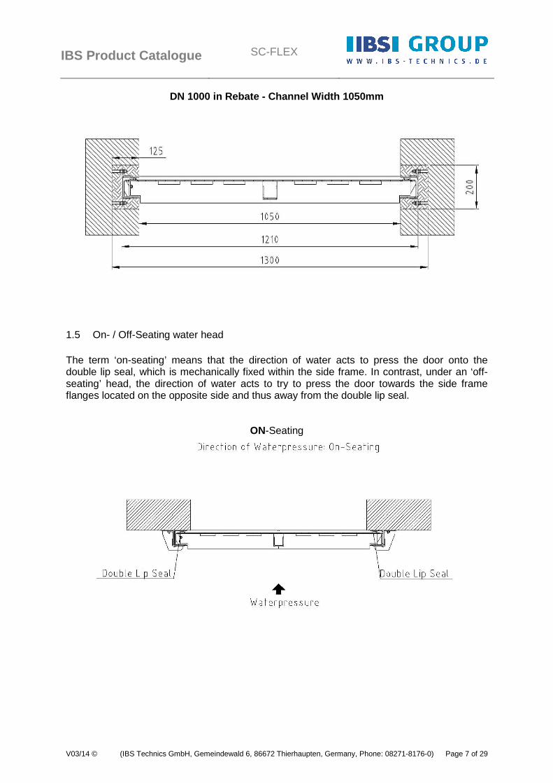
DN 1000 in Rebate - Channel Width 1050mm
1.5 On- / Off-Seating water head The term ‘on-seating’ means that the direction of water acts to press the door onto the double lip seal, which is mechanically fixed within the side frame. In contrast, under an ‘off-seating’ head, the direction of water acts to try to press the door towards the side frame flanges located on the opposite side and thus away from the double lip seal.
ON-Seating
IBS Product Catalogue
SC-FLEX
V03/14 © (IBS Technics GmbH, Gemeindewald 6, 86672 Thierhaupten, Germany, Phone: 08271-8176-0) Page 8 of 29
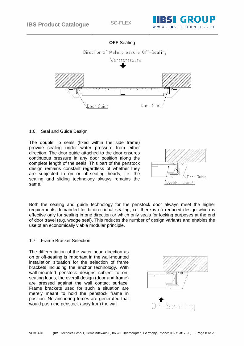
OFF-Seating
1.6 Seal and Guide Design The double lip seals (fixed within the side frame) provide sealing under water pressure from either direction. The door guide attached to the door ensures continuous pressure in any door position along the complete length of the seals. This part of the penstock design remains constant regardless of whether they are subjected to on or off-seating heads, i.e. the sealing and sliding technology always remains the same.
Both the sealing and guide technology for the penstock door always meet the higher requirements demanded for bi-directional sealing, i.e. there is no reduced design which is effective only for sealing in one direction or which only seals for locking purposes at the end of door travel (e.g. wedge seal). This reduces the number of design variants and enables the use of an economically viable modular principle.
1.7 Frame Bracket Selection The differentiation of the water head direction as on or off-seating is important in the wall-mounted installation situation for the selection of frame brackets including the anchor technology. With wall-mounted penstock designs subject to on-seating loads, the overall design (door and frame) are pressed against the wall contact surface. Frame brackets used for such a situation are merely meant to hold the penstock frame in position. No anchoring forces are generated that would push the penstock away from the wall.
IBS Product Catalogue
SC-FLEX
V03/14 © (IBS Technics GmbH, Gemeindewald 6, 86672 Thierhaupten, Germany, Phone: 08271-8176-0) Page 9 of 29
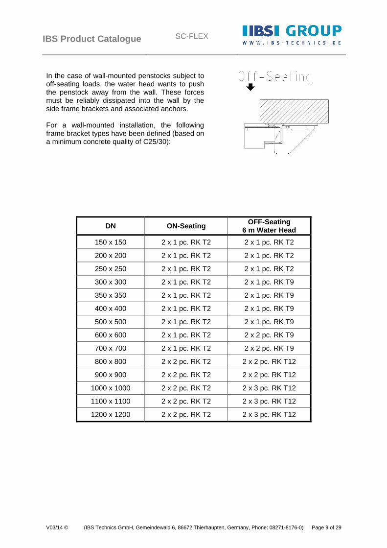
In the case of wall-mounted penstocks subject to off-seating loads, the water head wants to push the penstock away from the wall. These forces must be reliably dissipated into the wall by the side frame brackets and associated anchors. For a wall-mounted installation, the following frame bracket types have been defined (based on a minimum concrete quality of C25/30):
DN ON-Seating OFF-Seating 6 m Water Head
150 x 150 2 x 1 pc. RK T2 2 x 1 pc. RK T2
200 x 200 2 x 1 pc. RK T2 2 x 1 pc. RK T2
250 x 250 2 x 1 pc. RK T2 2 x 1 pc. RK T2
300 x 300 2 x 1 pc. RK T2 2 x 1 pc. RK T9
350 x 350 2 x 1 pc. RK T2 2 x 1 pc. RK T9
400 x 400 2 x 1 pc. RK T2 2 x 1 pc. RK T9
500 x 500 2 x 1 pc. RK T2 2 x 1 pc. RK T9
600 x 600 2 x 1 pc. RK T2 2 x 2 pc. RK T9
700 x 700 2 x 1 pc. RK T2 2 x 2 pc. RK T9
800 x 800 2 x 2 pc. RK T2 2 x 2 pc. RK T12
900 x 900 2 x 2 pc. RK T2 2 x 2 pc. RK T12
1000 x 1000 2 x 2 pc. RK T2 2 x 3 pc. RK T12
1100 x 1100 2 x 2 pc. RK T2 2 x 3 pc. RK T12
1200 x 1200 2 x 2 pc. RK T2 2 x 3 pc. RK T12
IBS Product Catalogue
SC-FLEX
V03/14 © (IBS Technics GmbH, Gemeindewald 6, 86672 Thierhaupten, Germany, Phone: 08271-8176-0) Page 10 of 29
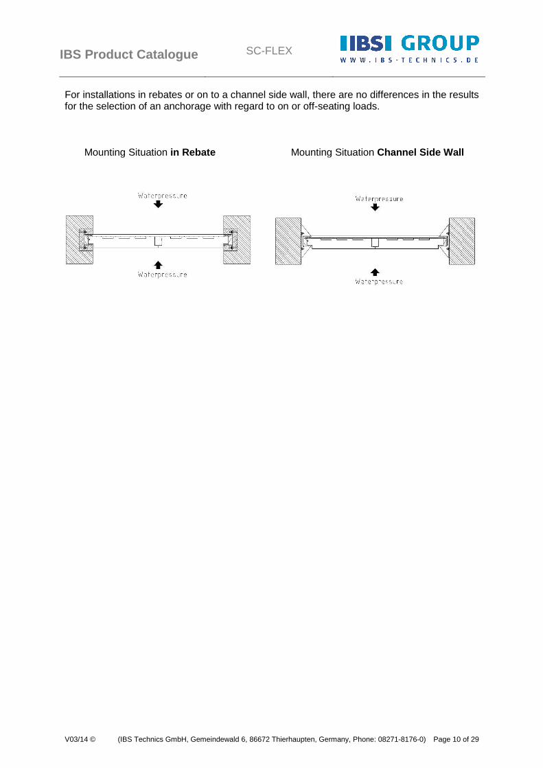
For installations in rebates or on to a channel side wall, there are no differences in the results for the selection of an anchorage with regard to on or off-seating loads. Mounting Situation in Rebate Mounting Situation Channel Side Wall

IBS Product Catalogue
SC-FLEX
V03/14 © (IBS Technics GmbH, Gemeindewald 6, 86672 Thierhaupten, Germany, Phone: 08271-8176-0) Page 11 of 29
2 Materials The following stainless steel materials can be selected as standard materials for component production:
- Material number 1.4301(304) - Material number 1.4404 (316)
In the following table, all the materials used in the components are listed:
Component Materials
Frame / Door / Yoke 1.4301 / 1.4404
Spindle 1.4305 / 1.4404
Spindle Protection Tube DN 400 to DN 600 PE
Spindle Protection Tube DN 600 to DN 1200 1.4301 / 1.4404
Spindle Nut RG 7
Spindle Extension 1.4301 / 1.4404
Spindle Guide Bracket POM + 1.4404
Frame-, Floor Bracket 1.4301 / 1.4404
Channel Side Wall Bracket 1.4301 / 1.4404
Pedestal, Wall Bracket 1.4301
Clamping Strip 1.4301 / 1.4404
Bolts / Nuts /Washers A2 / A4
Double Lip Seal EPDM / Elastosil
Invert Seal EPDM / Elastosil
Anchorage A4
Compression Cord PU-Cord 20/4 grey self adhesive
Sealant PU - Bond + Seal
IBS Product Catalogue
SC-FLEX
V03/14 © (IBS Technics GmbH, Gemeindewald 6, 86672 Thierhaupten, Germany, Phone: 08271-8176-0) Page 12 of 29
3 Frame Mounting Types
3.1 General
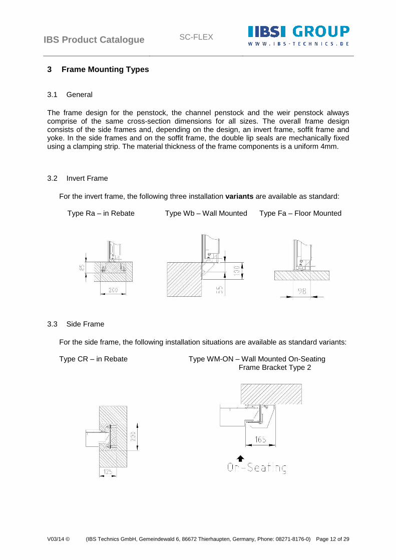
The frame design for the penstock, the channel penstock and the weir penstock always comprise of the same cross-section dimensions for all sizes. The overall frame design consists of the side frames and, depending on the design, an invert frame, soffit frame and yoke. In the side frames and on the soffit frame, the double lip seals are mechanically fixed using a clamping strip. The material thickness of the frame components is a uniform 4mm.
3.2 Invert Frame For the invert frame, the following three installation variants are available as standard: Type Ra – in Rebate Type Wb – Wall Mounted Type Fa – Floor Mounted
3.3 Side Frame
For the side frame, the following installation situations are available as standard variants: Type CR – in Rebate Type WM-ON – Wall Mounted On-Seating Frame Bracket Type 2

IBS Product Catalogue
SC-FLEX
V03/14 © (IBS Technics GmbH, Gemeindewald 6, 86672 Thierhaupten, Germany, Phone: 08271-8176-0) Page 13 of 29
Type WM-OF – Wall Mounted Off-Seating
Frame Bracket Type 9 Frame Bracket Type 12
Type CS – Channel Side Wall Mounted
3.4 Soffit Frame

IBS Product Catalogue
SC-FLEX
V03/14 © (IBS Technics GmbH, Gemeindewald 6, 86672 Thierhaupten, Germany, Phone: 08271-8176-0) Page 14 of 29
3.5 Yoke
3.5.1 Design for DN 150 to DN 500
3.5.2 Design for DN 600 to DN 1200

IBS Product Catalogue
SC-FLEX
V03/14 © (IBS Technics GmbH, Gemeindewald 6, 86672 Thierhaupten, Germany, Phone: 08271-8176-0) Page 15 of 29
4 Operation Types
4.1 Manual Operation
4.1.1 Cap Top
4.1.2 Handwheel
d = 250mm d = 315mm d = 500mm
4.1.3 Handwheel d = 315mm with Bevel Gearbox GK 10.2 or GK 14.2 (2:1) (2,8:1)
4.2 Electric Multi-turn Actuator
Multi-turn-Actuator
without Control with Bevel Gearbox with Control

IBS Product Catalogue
SC-FLEX
V03/14 © (IBS Technics GmbH, Gemeindewald 6, 86672 Thierhaupten, Germany, Phone: 08271-8176-0) Page 16 of 29
4.3 Cylinder Pistons
4.3.1 Pneumatic Actuated
4.3.2 Hydraulic Actuated
4.4 Standard Operation Specifications
With a water pressure of up to 6.0m, an operation type can be selected with the aid of the following information:
IBS Product Catalogue
SC-FLEX
V03/14 © (IBS Technics GmbH, Gemeindewald 6, 86672 Thierhaupten, Germany, Phone: 08271-8176-0) Page 17 of 29
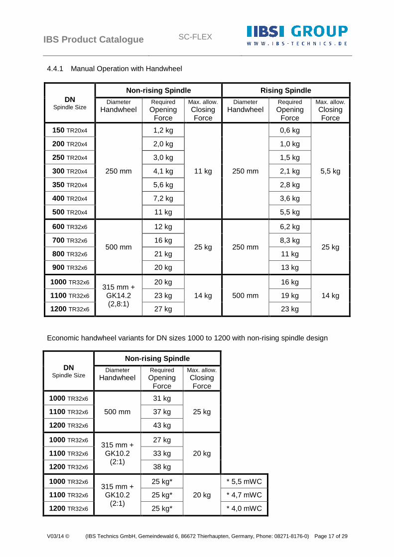
4.4.1 Manual Operation with Handwheel
DN Spindle Size
Non-rising Spindle Rising Spindle
Diameter Handwheel
Required Opening
Force
Max. allow. Closing Force
Diameter Handwheel
Required Opening
Force
Max. allow. Closing Force
150 TR20x4
250 mm
1,2 kg
11 kg 250 mm
0,6 kg
5,5 kg
200 TR20x4 2,0 kg 1,0 kg
250 TR20x4 3,0 kg 1,5 kg
300 TR20x4 4,1 kg 2,1 kg
350 TR20x4 5,6 kg 2,8 kg
400 TR20x4 7,2 kg 3,6 kg
500 TR20x4 11 kg 5,5 kg
600 TR32x6
500 mm
12 kg
25 kg 250 mm
6,2 kg
25 kg 700 TR32x6 16 kg 8,3 kg
800 TR32x6 21 kg 11 kg
900 TR32x6 20 kg 13 kg
1000 TR32x6 315 mm + GK14.2 (2,8:1)
20 kg
14 kg 500 mm
16 kg
14 kg 1100 TR32x6 23 kg 19 kg
1200 TR32x6 27 kg 23 kg
Economic handwheel variants for DN sizes 1000 to 1200 with non-rising spindle design
DN Spindle Size
Non-rising Spindle
Diameter Handwheel
Required Opening
Force
Max. allow. Closing Force
1000 TR32x6
500 mm
31 kg
25 kg 1100 TR32x6 37 kg
1200 TR32x6 43 kg
1000 TR32x6 315 mm + GK10.2
(2:1)
27 kg
20 kg 1100 TR32x6 33 kg
1200 TR32x6 38 kg
1000 TR32x6 315 mm + GK10.2
(2:1)
25 kg*
20 kg
* 5,5 mWC
1100 TR32x6 25 kg* * 4,7 mWC
1200 TR32x6 25 kg* * 4,0 mWC
IBS Product Catalogue
SC-FLEX
V03/14 © (IBS Technics GmbH, Gemeindewald 6, 86672 Thierhaupten, Germany, Phone: 08271-8176-0) Page 18 of 29
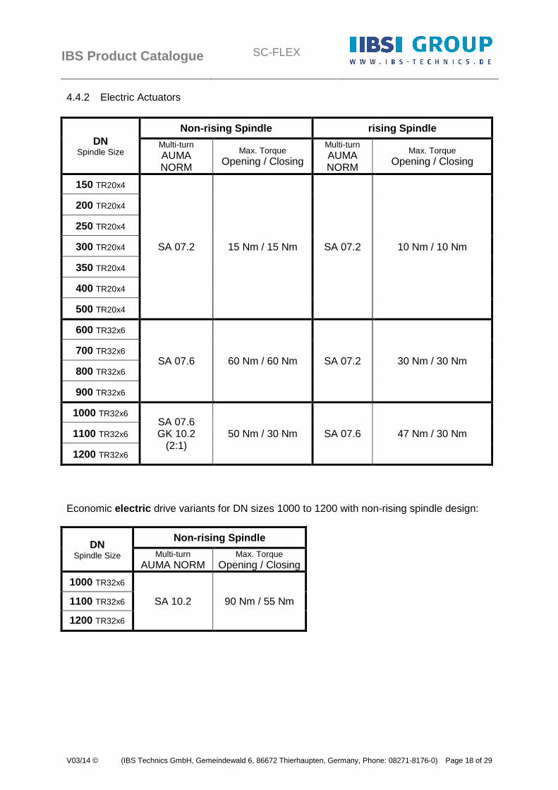
4.4.2 Electric Actuators
DN Spindle Size
Non-rising Spindle rising Spindle
Multi-turn AUMA NORM
Max. Torque Opening / Closing
Multi-turn AUMA NORM
Max. Torque Opening / Closing
150 TR20x4
SA 07.2 15 Nm / 15 Nm SA 07.2 10 Nm / 10 Nm
200 TR20x4
250 TR20x4
300 TR20x4
350 TR20x4
400 TR20x4
500 TR20x4
600 TR32x6
SA 07.6 60 Nm / 60 Nm SA 07.2 30 Nm / 30 Nm 700 TR32x6
800 TR32x6
900 TR32x6
1000 TR32x6 SA 07.6 GK 10.2
(2:1) 50 Nm / 30 Nm SA 07.6 47 Nm / 30 Nm 1100 TR32x6
1200 TR32x6
Economic electric drive variants for DN sizes 1000 to 1200 with non-rising spindle design:
DN Spindle Size
Non-rising Spindle
Multi-turn AUMA NORM
Max. Torque Opening / Closing
1000 TR32x6
SA 10.2 90 Nm / 55 Nm 1100 TR32x6
1200 TR32x6
IBS Product Catalogue
SC-FLEX
V03/14 © (IBS Technics GmbH, Gemeindewald 6, 86672 Thierhaupten, Germany, Phone: 08271-8176-0) Page 19 of 29
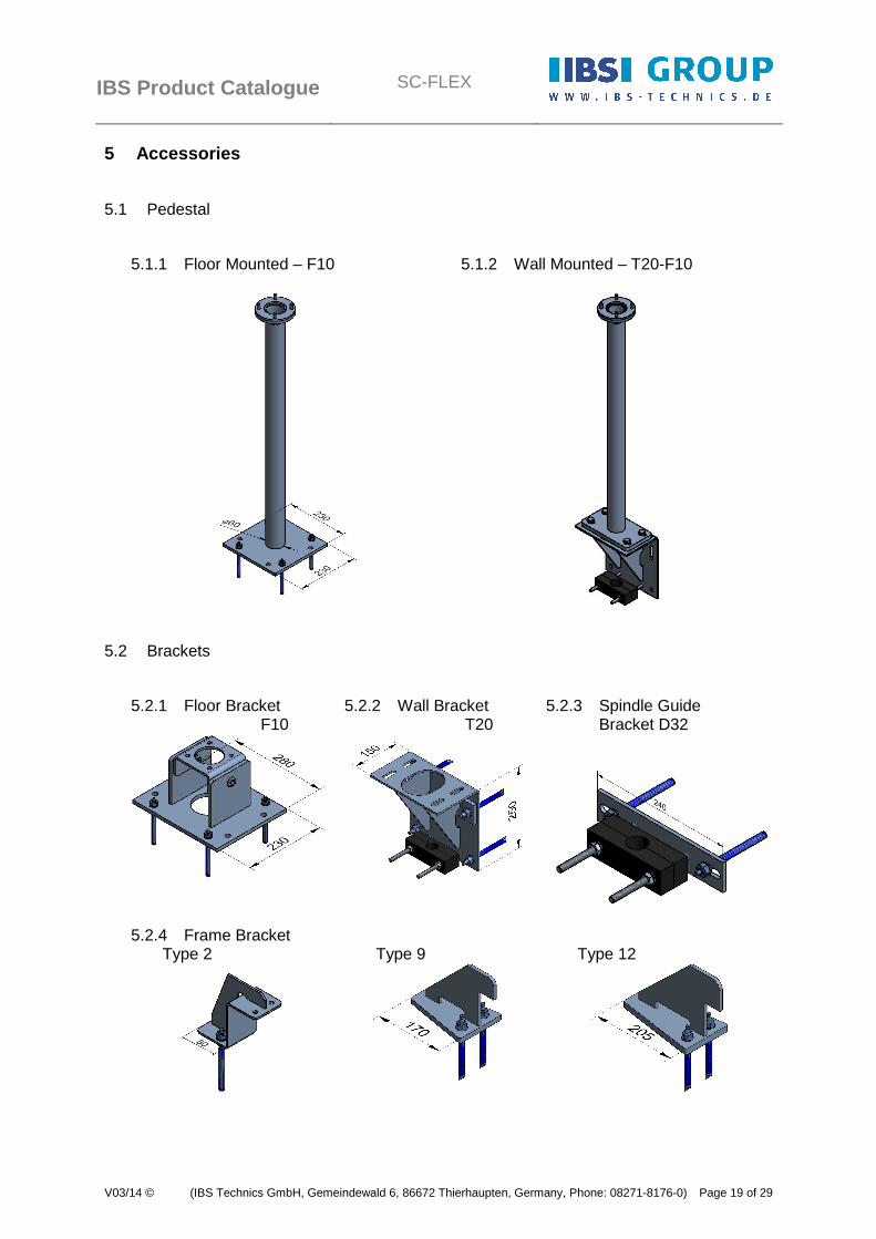
5 Accessories
5.1 Pedestal
5.1.1 Floor Mounted – F10
5.1.2 Wall Mounted – T20-F10
5.2 Brackets
5.2.1 Floor Bracket F10
5.2.2 Wall Bracket T20
5.2.3 Spindle Guide Bracket D32
5.2.4 Frame Bracket
Type 2 Type 9 Type 12
IBS Product Catalogue
SC-FLEX
V03/14 © (IBS Technics GmbH, Gemeindewald 6, 86672 Thierhaupten, Germany, Phone: 08271-8176-0) Page 20 of 29
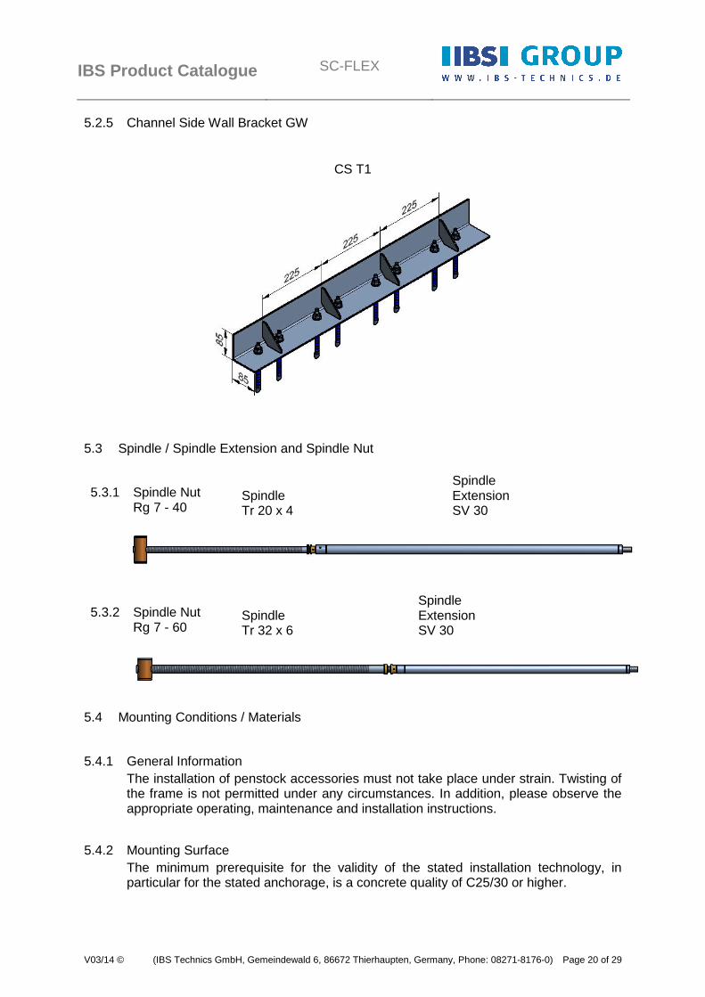
5.2.5 Channel Side Wall Bracket GW
CS T1
5.3 Spindle / Spindle Extension and Spindle Nut
5.3.1 Spindle Nut Rg 7 - 40
Spindle Tr 20 x 4
Spindle Extension SV 30
5.3.2 Spindle Nut Rg 7 - 60
Spindle Tr 32 x 6
Spindle Extension SV 30
5.4 Mounting Conditions / Materials
5.4.1 General Information The installation of penstock accessories must not take place under strain. Twisting of the frame is not permitted under any circumstances. In addition, please observe the appropriate operating, maintenance and installation instructions.
5.4.2 Mounting Surface The minimum prerequisite for the validity of the stated installation technology, in particular for the stated anchorage, is a concrete quality of C25/30 or higher.

IBS Product Catalogue
SC-FLEX
V03/14 © (IBS Technics GmbH, Gemeindewald 6, 86672 Thierhaupten, Germany, Phone: 08271-8176-0) Page 21 of 29
5.4.3 Evenness / Tolerances Construction tolerances: Surface unevenness of up to ± 2mm are accommodated using the sealing materials recommended for installation.
5.4.4 Anchorage The following list of anchor technology is purely for information purposes. In individual cases, numerous factors such as edge clearances, concrete strengths, concrete conditions, etc. play a major role in selecting the correctly dimensioned anchor technology. The correct selection of anchor technology is the responsibility of the person providing it for the purposes of installation.
Components Examples for Anchorage Materials
Pedestal Floor Mounted 4 x Anchor Rod HAS-R M10x90/21+ 4 x Adhesive capsule HVU M10x90
Floor Bracket 4 x Anchor Rod HAS-R M10x90/21+ 4 x Adhesive capsule HVU M10x90
Wall Bracket T20 2 x Washer 40x60x10 4 x Anchor Rod HAS-RTZ M12x95/25+ 4 x Adhesive capsule HVU-TZ M12x95
Spindle Guide Bracket 2 x Anchor Rod HAS-R M10x90/21+ 2 x Adhesive capsule HVU M10x90
Frame Bracket T2 1 x Anchor Rod HAS-R M10x90/21+ 1 x Adhesive capsule HVU M10x90
Frame Bracket T9 2 x Anchor Rod HAS-RTZ M12x95/25+ 2 x Adhesive capsule HVU-TZ M12x95
Frame Bracket T12 2 x Anchor Rod HAS-RTZ M12x95/25+ 2 x Adhesive capsule HVU-TZ M12x95
Channel Side Wall Bracket T1
Anchor Rod HAS-RTZ M12x95/25+ Adhesive capsule HVU-TZ M12x95
Frame Fixing (in Rebate)
Anchor Rod HAS-R M10x90/21+ Adhesive capsule HVU M10x90
Soffit Frame Flush Anchor HKD-SR M8x30+ Hexagon Bolt DIN 933 M8x20+ Washer DIN 9021 8
Invert Frame Ra Anchor Rod HAS-R M10x90/21+ Adhesive capsule HVU M10x90
Invert Frame Wb Anchor Rod HAS-R M10x90/21+ Adhesive capsule HVU M10x90
Invert Frame Fa Flush Anchor HKD-SR M8x30+ Countersunk Bolt DIN7991 M 8x16

IBS Product Catalogue
SC-FLEX
V03/14 © (IBS Technics GmbH, Gemeindewald 6, 86672 Thierhaupten, Germany, Phone: 08271-8176-0) Page 22 of 29
5.4.5 Sealing to Concrete Surface Two sealing lines are provided for adequate sealing between the frame components and the installation surface. One of these is a double-row, self-adhesive sealing tape (Kompriband 20/4 grey) running along the entire channel aperture, which is to be adhered onto the contact surface of the frame components. When the penstock frame is then attached to the wall, the sealing tape is compressed between frame and wall. When the frame is fixed, the sealing tape equalizes any unevenness in the contact surface up to a tolerance of ±2mm. The second sealing line is in the form of an adhesive seam made of PU-Klebt+Dichtet along the frame flange around the clear frame aperture. If the frame is grouted, for example when installed into a rebate or to a channel side wall-mounted, no further sealing measures are required. The sealing process between the frame and the surrounding construction is ensured through a non-shrinking grouting mortar, which is to be applied carefully and without faults or gaps.
6 Model Types
6.1 General
The position of the spindle and the load transfer from the movement process is shown through the model types 1, 2, 3 or 4. Model 1 defines a non-rising spindle and model 2 a rising spindle, which each transmit the opening/closing forces onto the penstock yoke, which is attached to the side frames. Due to the enclosed flow of force in the frame and yoke design resulting from the penstock door movement process, we designate the construction type of models 1 and 2 as self-contained. Model 3 defines a non-rising spindle and model 4 a rising spindle, which each transmit the opening/closing forces onto a sub-assembly independent of the frame (e.g. operating console, pedestal, bridge etc.) Due to the forces transmitted via the sub-assembly, usually directly into the adjacent wall via the anchorage, we designate the construction type of models 3 and 4 as open, i.e. an open frame penstock design without yoke is used.
Model Definition Non-rising Spindle rising Spindle
Frame self-contained M1 M2
Frame open M3 (telescopic) M4
IBS Product Catalogue
SC-FLEX
V03/14 © (IBS Technics GmbH, Gemeindewald 6, 86672 Thierhaupten, Germany, Phone: 08271-8176-0) Page 23 of 29
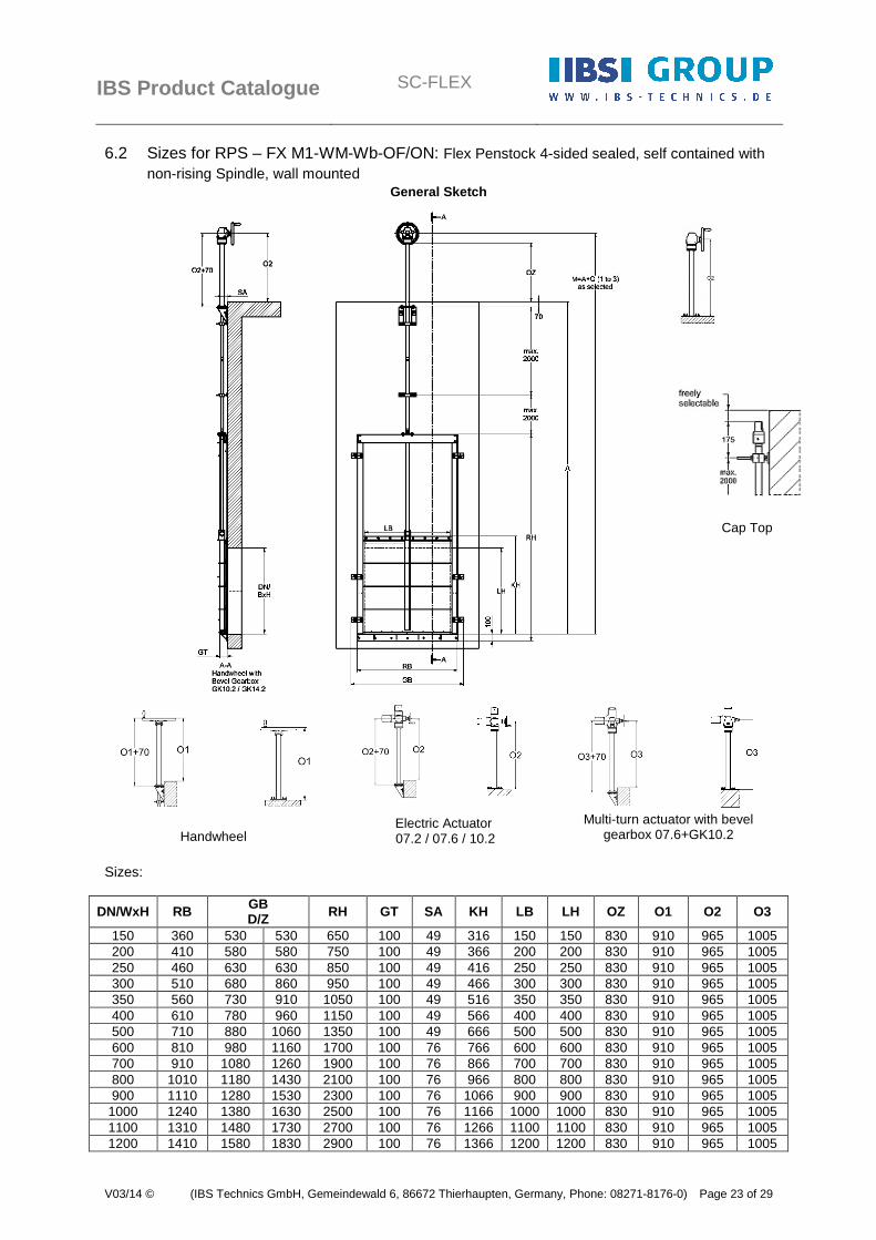
6.2 Sizes for RPS – FX M1-WM-Wb-OF/ON: Flex Penstock 4-sided sealed, self contained with non-rising Spindle, wall mounted
General Sketch
Cap Top
Handwheel
Electric Actuator 07.2 / 07.6 / 10.2
Multi-turn actuator with bevel
gearbox 07.6+GK10.2
Sizes:
DN/WxH RB GB D/Z RH GT SA KH LB LH OZ O1 O2 O3
150 360 530 530 650 100 49 316 150 150 830 910 965 1005 200 410 580 580 750 100 49 366 200 200 830 910 965 1005 250 460 630 630 850 100 49 416 250 250 830 910 965 1005 300 510 680 860 950 100 49 466 300 300 830 910 965 1005 350 560 730 910 1050 100 49 516 350 350 830 910 965 1005 400 610 780 960 1150 100 49 566 400 400 830 910 965 1005 500 710 880 1060 1350 100 49 666 500 500 830 910 965 1005 600 810 980 1160 1700 100 76 766 600 600 830 910 965 1005 700 910 1080 1260 1900 100 76 866 700 700 830 910 965 1005 800 1010 1180 1430 2100 100 76 966 800 800 830 910 965 1005 900 1110 1280 1530 2300 100 76 1066 900 900 830 910 965 1005
1000 1240 1380 1630 2500 100 76 1166 1000 1000 830 910 965 1005 1100 1310 1480 1730 2700 100 76 1266 1100 1100 830 910 965 1005 1200 1410 1580 1830 2900 100 76 1366 1200 1200 830 910 965 1005

IBS Product Catalogue
SC-FLEX
V03/14 © (IBS Technics GmbH, Gemeindewald 6, 86672 Thierhaupten, Germany, Phone: 08271-8176-0) Page 24 of 29
6.3 Sizes for RSG – FX M2-CS-F: Flex Channel Penstock 3-sided sealed, self contained with rising Spindle, channel side wall mounted
General Sketch
Handwheel with Bevel Gearbox GK10.2 / GK14.2
Electric Actuator 07.2 / 07.6 / 10.2
Electric Actuator with Bevel
Gearbox 07.6+GK10.2
Sizes:
GB LB DN/B RB DH RH min. GH O1 O2 O3
800 600 550 760 673 1550 1710 160 145 185
900 700 650 860 773 1750 1910 160 145 185
1000 800 750 960 873 1950 2110 160 145 185
1100 900 850 1060 973 2150 2310 160 145 185
1200 1000 950 1160 1073 2300 2460 160 145 185
1300 1100 1050 1260 1173 2500 2660 160 145 185
1400 1200 1150 1360 1273 2700 2860 160 145 185

IBS Product Catalogue
SC-FLEX
V03/14 © (IBS Technics GmbH, Gemeindewald 6, 86672 Thierhaupten, Germany, Phone: 08271-8176-0) Page 25 of 29
6.4 Sizes for RSG – FX M2-CR-R: Flex Channel Penstock 3-sided sealed, self contained with rising Spindle, in rebate
General Sketch
Handwheel with Bevel Gearbox GK10.2 / GK14.2
Electric Actuator 07.2 / 07.6 / 10.2
Electric Actuator with Bevel
Gearbox 07.6+GK10.2
Sizes:
LB DN/B AB RB DH RH min. GH O1 O2 O3
600 550 850 760 669 1550 1710 160 145 185
700 650 950 860 769 1750 1910 160 145 185
800 750 1050 960 869 1950 2110 160 145 185
900 850 1150 1060 969 2150 2310 160 145 185
1000 950 1250 1160 1069 2300 2460 160 145 185
1100 1050 1350 1260 1169 2500 2660 160 145 185
1200 1150 1450 1360 1269 2700 2860 160 145 185
IBS Product Catalogue
SC-FLEX
V03/14 © (IBS Technics GmbH, Gemeindewald 6, 86672 Thierhaupten, Germany, Phone: 08271-8176-0) Page 26 of 29
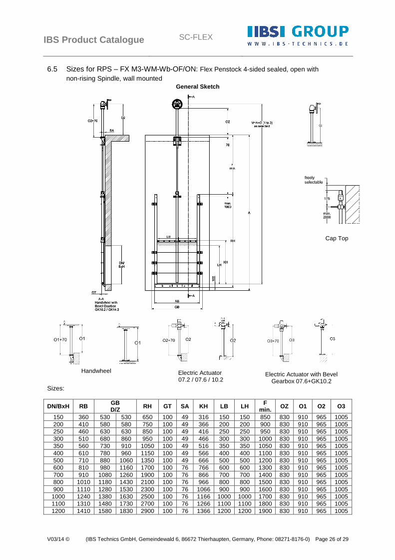
6.5 Sizes for RPS – FX M3-WM-Wb-OF/ON: Flex Penstock 4-sided sealed, open with non-rising Spindle, wall mounted
General Sketch
Cap Top
Handwheel
Electric Actuator 07.2 / 07.6 / 10.2
Electric Actuator with Bevel Gearbox 07.6+GK10.2
Sizes:
DN/BxH RB GB D/Z RH GT SA KH LB LH F
min. OZ O1 O2 O3
150 360 530 530 650 100 49 316 150 150 850 830 910 965 1005 200 410 580 580 750 100 49 366 200 200 900 830 910 965 1005 250 460 630 630 850 100 49 416 250 250 950 830 910 965 1005 300 510 680 860 950 100 49 466 300 300 1000 830 910 965 1005 350 560 730 910 1050 100 49 516 350 350 1050 830 910 965 1005 400 610 780 960 1150 100 49 566 400 400 1100 830 910 965 1005 500 710 880 1060 1350 100 49 666 500 500 1200 830 910 965 1005 600 810 980 1160 1700 100 76 766 600 600 1300 830 910 965 1005 700 910 1080 1260 1900 100 76 866 700 700 1400 830 910 965 1005 800 1010 1180 1430 2100 100 76 966 800 800 1500 830 910 965 1005 900 1110 1280 1530 2300 100 76 1066 900 900 1600 830 910 965 1005
1000 1240 1380 1630 2500 100 76 1166 1000 1000 1700 830 910 965 1005 1100 1310 1480 1730 2700 100 76 1266 1100 1100 1800 830 910 965 1005 1200 1410 1580 1830 2900 100 76 1366 1200 1200 1900 830 910 965 1005

IBS Product Catalogue
SC-FLEX
V03/14 © (IBS Technics GmbH, Gemeindewald 6, 86672 Thierhaupten, Germany, Phone: 08271-8176-0) Page 27 of 29
6.6 Sizes for RPS – FX M4-WM-Wb-OF/ON: Flex Penstock 4-sided sealed, open with rising Spindle, wall mounted
General Sketch
Handwheel with Bevel Gearbox
GK10.2 / GK14.2
Electric Actuator 07.2 / 07.6 / 10.2
Electric Actuator with Bevel
Gearbox 07.6+GK10.2
Sizes:
DN/BxH RB GB D/Z RH GT SA KH LB LH OZ O1 O2 O3
150 360 530 530 650 100 49 316 150 150 830 910 965 1005 200 410 580 580 750 100 49 366 200 200 830 910 965 1005 250 460 630 630 850 100 49 416 250 250 830 910 965 1005 300 510 680 860 950 100 49 466 300 300 830 910 965 1005 350 560 730 910 1050 100 49 516 350 350 830 910 965 1005 400 610 780 960 1150 100 49 566 400 400 830 910 965 1005 500 710 880 1060 1350 100 49 666 500 500 830 910 965 1005 600 810 980 1160 1700 100 76 766 600 600 830 910 965 1005 700 910 1080 1260 1900 100 76 866 700 700 830 910 965 1005 800 1010 1180 1430 2100 100 76 966 800 800 830 910 965 1005 900 1110 1280 1530 2300 100 76 1066 900 900 830 910 965 1005
1000 1240 1380 1630 2500 100 76 1166 1000 1000 830 910 965 1005 1100 1310 1480 1730 2700 100 76 1266 1100 1100 830 910 965 1005 1200 1410 1580 1830 2900 100 76 1366 1200 1200 830 910 965 1005

IBS Product Catalogue
SC-FLEX
V03/14 © (IBS Technics GmbH, Gemeindewald 6, 86672 Thierhaupten, Germany, Phone: 08271-8176-0) Page 28 of 29
6.7 Sizes for RWG – FX M1-WM-Wb-OF/ON: Flex Weir Penstock 3-sided sealed, self contained with non-rising Spindle, wall mounted
General Sketch
Handwheel with Bevel Gearbox
GK10.2 / GK14.2
Cap Top
Handwheel
Electric Actuator 07.2 / 07.6 / 10.2
Electric Actuator with Bevel Gearbox 07.6+GK10.2
Sizes:
DN/BxH RB GB D/Z
RH min. GH GT SA KH LB LH OZ O1 O2 O3
150 360 530 530 650 803 100 49 225 150 150 830 910 965 1005 200 410 580 580 750 903 100 49 275 200 200 830 910 965 1005 250 460 630 630 850 1003 100 49 325 250 250 830 910 965 1005 300 510 680 860 950 1103 100 49 375 300 300 830 910 965 1005 350 560 730 910 1050 1203 100 49 425 350 350 830 910 965 1005 400 610 780 960 1150 1303 100 49 475 400 400 830 910 965 1005 500 710 880 1060 1350 1503 100 49 575 500 500 830 910 965 1005 600 810 980 1160 1700 1703 100 76 675 600 600 830 910 965 1005 700 910 1080 1260 1900 1903 100 76 775 700 700 830 910 965 1005 800 1010 1180 1430 2100 2103 100 76 875 800 800 830 910 965 1005 900 1110 1280 1530 2300 2303 100 76 975 900 900 830 910 965 1005
1000 1240 1380 1630 2500 2503 100 76 1075 1000 1000 830 910 965 1005 1100 1310 1480 1730 2700 2703 100 76 1175 1100 1100 830 910 965 1005 1200 1410 1580 1830 2900 2903 100 76 1275 1200 1200 830 910 965 1005
IBS Product Catalogue
SC-FLEX
V03/14 © (IBS Technics GmbH, Gemeindewald 6, 86672 Thierhaupten, Germany, Phone: 08271-8176-0) Page 29 of 29
Contact: IBS Industriebarrieren und Brandschutztechnik Planungs- und Vertriebsgesellschaft mbH Am Gemeindewald 4-6 86672 Thierhaupten Germany
Phone: +49 8271 – 8176-0 Fax: +49 8271 – 8176-76 www.ibs-technik.de [email protected]