Production Technology 2 -sample-chapter - · PDF fileMECHANICAL PRODUCTION 2 3 | P a g e THE...
18
MECHANICAL PRODUCTION 2 1 | Page THE GATE COACH All Rights Reserved 28, Jia Sarai N.Delhi-16, 26528213,-9998
Transcript of Production Technology 2 -sample-chapter - · PDF fileMECHANICAL PRODUCTION 2 3 | P a g e THE...

MECHANICAL PRODUCTION 2
1 | P a g e THE GATE COACH All Rights Reserved 28, Jia Sarai N.Delhi-16, 26528213,-9998
MECHANICAL PRODUCTION 2
2 | P a g e THE GATE COACH All Rights Reserved 28, Jia Sarai N.Delhi-16, 26528213,-9998
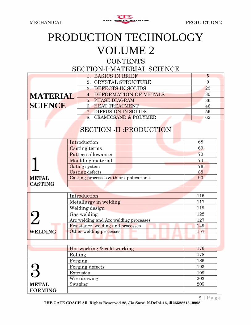
PRODUCTION TECHNOLOGY
VOLUME 2 CONTENTS
SECTION-I:MATERIAL SCIENCE
MATERIAL
SCIENCE
1. BASICS IN BRIEF 5
2. CRYSTAL STRUCTURE 9
3. DEFECTS IN SOLIDS 23
4. DEFORMATION OF METALS 30
5. PHASE DIAGRAM 36
6. HEAT TREATMENT 46
7. DIFFUSION IN SOLIDS 59
8. CRAMICSAND & POLYMER 62
SECTION -II :PRODUCTION
1 METAL
CASTING
Introduction 68
Casting terms 69
Pattern allowances 70
Moulding material 74
Gating system 76
Casting defects 88
Casting processes & their applications 90
2 WELDING
Introduction 116
Metallurgy in welding 117
Welding design 119
Gas welding 122
Arc welding and Arc welding processes 127
Resistance welding and processes 149
Other welding processes 157
3 METAL
FORMING
Hot working & cold working 176
Rolling 178
Forging 186
Forging defects 193
Extrusion 199
Wire drawing 203
Swaging 205
MECHANICAL PRODUCTION 2
3 | P a g e THE GATE COACH All Rights Reserved 28, Jia Sarai N.Delhi-16, 26528213,-9998
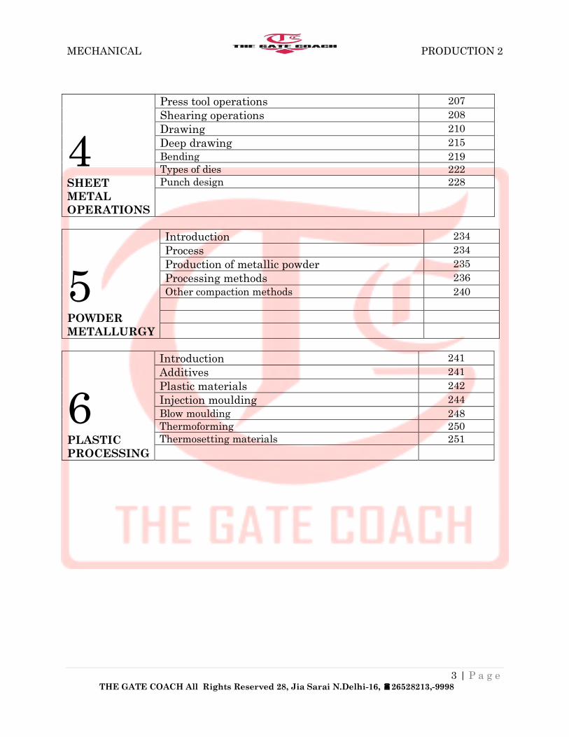
4 SHEET
METAL
OPERATIONS
Press tool operations 207
Shearing operations 208
Drawing 210
Deep drawing 215
Bending 219
Types of dies 222
Punch design 228
5 POWDER
METALLURGY
Introduction 234
Process 234
Production of metallic powder 235
Processing methods 236
Other compaction methods 240
6 PLASTIC
PROCESSING
Introduction 241
Additives 241
Plastic materials 242
Injection moulding 244
Blow moulding 248
Thermoforming 250
Thermosetting materials 251

MECHANICAL PRODUCTION 2
4 | P a g e THE GATE COACH All Rights Reserved 28, Jia Sarai N.Delhi-16, 26528213,-9998
CHAPTER 6 PLASTIC PROCESSING
Polymers are new materials that have been extensively used in engineering, starting from the
nineteenth century. A monomer is the single building block used in creating the polymer by the
process of polymerization. A polymer is basically a linked monomer with a number of them
being linked based on the type of the polymer. Most of the polymers are based on carbon and to
that extent they are called organic materials. However, there are certain inorganic polymers also
in existence.
Plastics are formed when small organic molecules are stitched together to form a long chain.
This process is called polymerization. Those organic molecules suitable for polymerization are
called monomers. It is necessary for a monomer to be at least biftinctional (capable of forming
two covalent bonds) to polymerize. The afunctional monomer will attach other monomers at the
front and back end to form a chain. Some monomers | polyfunctional, capable of forming three
or more bonds. These can form three-dimensional arrangements 'chains called a network.
In condensation polymerization, two different organic molecules react to form a plastic
molecule. The reaction generally results in the separation of a small molecule such as H20 as a
by-product.
Resin is the term generally used for uncompounded ingredients or monomers that are mixed but
not yet polymerized. An example is thermosetting resin. Sometimes it is also used as a
synonymous term for plastics, for example, thermoplastic resin instead of thermoplastic material.
As polymerization proceeds, the number of carbon chains will intermingle to form large
volumes. Depend-g on the orderliness of these chains, the polymers will be termed amorphous
(disorderly) or crystalline (orderly). Crystallinity or orderliness of the chains control the
properties of the plastics. Amorphous polymers are less dense compared to crystalline plastics.
Crystallinity in plastics increases the strength and toughness.
ADDITIVES
A number of additives are normally used with the plastic materials to modify their behaviour,
improve properties or reduce the overall cost thereby increasing the range of application of
plastics.
Plasticizers
They are mixed with plastics to improve their flow characteristics and decrease their brittleness.
These are liquid organic compounds with fairly large molecular weight. The glass transition
temperature is the temperature at which an amorphous polymer becomes brittle on cooling, or
soft on heating. Plasticizers er the glass transition temperature thus making the plastic softer and
more flexible at room temperature, example, polyvinyl chloride (PVC) is brittle at the room
temperature. However, when a plasticizer such as di-iso-octyl is mixed, PVC becomes flexible
and is used as wrapping tape for electrical insulation.

MECHANICAL PRODUCTION 2
5 | P a g e THE GATE COACH All Rights Reserved 28, Jia Sarai N.Delhi-16, 26528213,-9998
Fillers
Fillers are inexpensive materials that are added to plastics to reduce their cost. They are generally
inert and will not react with plastics. However, many of the filler materials increase the hardness
and impact strength of plastics. Common fillers are wood flour, quartz, glass spheres, talc,
calcium carbonate and alumina trihydrate.
Flame retardants
They are added to plastics to reduce the flammability of plastics by preventing oxygen reac-tion
and improving charring. Elements such as boron, nitrogen, chlorine, antimony and phosphorous
are added for this purpose. These can sometimes cause problems by reducing flexibility, tear
resistance, tensile strength and heat deflection.
Reinforcing agents They are the materials that are specifically added to plastic materials to raise their mechanical
properties. Reinforcing can affect practically all of the properties.
Stabilizersare used to stabilize the properties of the plastic throughout its useful life. They resist
heat, strength deterioration and reduce the effect of radiation on bonds within the chains.
Colourantsare used to give colour to the plastics. Both organic dyes and inorganic pigments are
used to add colour to plastic materials. Pigments disperse rather than dissolve in plastics thereby
reducing transparency of the material. They hide flaws such as air bubbles, making it difficult to
judge quality.
PLASTIC MATERIALS
Polymeric materials of interest to engineers can be broadly classified into plastics and. Plastic
materials are further classified into thermoplastic and thermosetting materials, based on the
processing methods.
Thermoplastics
These are the plastics that can be softened and melted by heat and can then be formed into the
required shape when they are hot. These materials can be melted a number of times. That means
it is possible to recycle thermoplastics. However, frequent remelting is avoided in industry since
some chemical degradation occurs during remelting. Thermoplastic materials tend to consist of
long polymer chains with little breadth, akin to a two-dimensional structure. The fabricati on
processes used for thermoplastics such as blow moulding, and injection moulding are less
expensive compared to those methods used for thermosetting materials. Some of the common
thermoplastic materials are given in Table 12.4 with their mechanical characteristics
Thermosetting Materials
These are the plastics that cannot be melted once they are solidified. The rawma for
thermosetting materials are usually called resins. They are mixed and placed in the mould, and
heated and compressed during which process the materials achieve the strength and hardness.
Polymerization occurs strong network bonds (cross-linking) with the application of heat,
pressure and/or time. The manufacturing processes are more expensive compared to those of

MECHANICAL PRODUCTION 2
6 | P a g e THE GATE COACH All Rights Reserved 28, Jia Sarai N.Delhi-16, 26528213,-9998
thermoplastic materials. These materials are by a three-dimensional network of molecules. These
materials cannot be recycled. When heated , these material burn and char.
EXTRUSION OF PLASTICS
Extrusion is the process of confining the material in a closed cavity and then allowing it to flow
flow from only one opening so that the metal will take the shape of the opening.
Extrusion can be used to process most thermoplastics such as polyethylene, polypropylene,
polyurethane, polystrene, polyamideypolyester, and flexible polyvinyl chloride. A characteristic
that often differentiates extruded from njection-moulded plastics is the viscosity of the plastic at
normal processing temperatures. Extruded plastics often have a higher melt viscosity that allows
the extrudate to retain the shape imparted to it by the die while the extrudate is in the cooling
stages.
It is possible to combine a variety of resins to gain special physical, biological or chemical
properties. Also, as explained earlier, additives that include lubricants, thermal stabilizers,
antioxidants and colorants, can be used during the extrusion process to enhance processing
characteristics of the polymer or to alter product properties.
1. The plastic that is generally in the form of pellets or granules is fed into the extruding
machine through a hopper. This machine is known as an extruder.
2. Pellets move into the barrel by gravity. The barrel is heated by electric heaters, which
soften the pellets in the barrel The screw moves the pellets contenuously and the
mechanical working and the friction generates more heat to soften the plastic. The
heating of the barrel may be reduced once sufficient heat is supplied. The rotating screw
has three main sections.
3. The pellets are moved from the hopper and preheated in the feed section. In the
compression section the plastic is softened sufficiently so that it flows smoothly like a
liquid.
4. Finally, in the metering section, the plastic is completely homogenized and sufficient
pressure is developed so that the material is forced through the die. The feeding capacity
of the screw is determined by its geometry and speed of rotation.
There is a breaker plate (a plate with several small holes) between the die and the barrel which
improves the mixing of the plastic before entering the die. The extruded product called extrudate
is cooled by blowing air or by passing through a water-filled channel.

MECHANICAL PRODUCTION 2
7 | P a g e THE GATE COACH All Rights Reserved 28, Jia Sarai N.Delhi-16, 26528213,-9998
The die is a metal plate placed at the end of the extruder with a cut-out of the shape of the cross
section of the manufacttired. Any complex external contour can be extruded with relatively
simple and inexpensive tooling
The parts for extrusion should have consistent wallthickness as it allows for an even flow of
material throughthe die that produces more controlled parts with a lowertooling cost. As far as
possible, designing profiles withhollow sections are avoided since they add significantly to the
cost of both the part and the tooling.
Solid Extrusion
This is the process that is described above. This produces a part with a uniform cross section
Hollow Extrusion
his process is used to extrude parts that have hollow cross sections such as pipes and tubes. The
dies used for this operation need to have special spider sections to form the hollow part. The dies
also need to have the streamlining sections built into the die to allow for the plastic to flow
smoothly. The dies are more expensive compared to those used for solid extrusion.
Co-extrusion
This is the process of extruding two or more materials through a single die with two or more
orifices arranged so that the extrudates from the multiple openings merge and weld together into
a laminar structure before chilling.
Extrusion Advantages
1. The equipment used is simple and relatively inexpensive.
2. It has short lead times since it uses simple dies which can be very quickly produced.
3. The tooling costs are relatively low.
4. Overall cost of the parts produced by extrusion is low.
5. Practically any cross section can be easily produced.
INJECTION MOULDING
MECHANICAL PRODUCTION 2
8 | P a g e THE GATE COACH All Rights Reserved 28, Jia Sarai N.Delhi-16, 26528213,-9998
Injection moulding is similar to pressure die casting. In this process, plastic material in a highly
softened state is forced to flow at high pressure through a nozzle into the mould cavity The
plastic solidifies in the die and then is ejected by opening the die. The shape of the component is
almost in its final form and can be produced in an extremely fast rate. Typical cycle times may
be of the order of 10 to 30 seconds. Unlike molten metal in diecasting, plastic melts have a high
viscosity and have to be injected with a large force into the hollow mould cavity. More melt must
also be packed into the mould during solidification to avoid shrinkage in the mould. Injection
moulding pressures usually range from 70 MPa to 200 MPa.
Injection moulding is the most widely used plastic-processing method.
1. It can be used to produce a wide variety of products.
2. Very complex parts can be produced whose sizes may range from very small (50 g) to
very large (25 kg) with excellent control of tolerances.
3. Most polymers may be injection moulded, including thermoplastics, fibre-reinforced
thermoplastics, thermosetting plastics and elastomers.
4. Structural injection moulding is also possible in which a core and skin may be made of
different polymers.
Reaction injectionmoulding and liquid injection moulding, which differ in the manner of mixing
ingredients, involve the injection of liquid polyurethane systems that polymerize within the
mould. Moulds with moving and unscrewing mandrels are not unusual, and allow the moulding
of parts with multiple cavities and internal and external threads. Metallic inserts such as screws,
pins and strips can also be placed in the mould cavity to become an integral part of the injection-
moulded product.
The machine can be broadly broken into two parts, an injection unit and a clamping unit.
The injection unit of the reciprocating screw type machine is very similar to the system described
for an extrusion machine. The function of the screw is to soften and pressurize the melt so that it
will be injected into the mould through. The plastic granules or pellets will be fed by gravity
from the hopper into the barrel. The rotating screw will move them through the plunger, while
receiving heat from the electric resistance heaters around jpl barrel. As the softened plastic
reaches the end of the barrel, the screw acts like a ram and then pushes the plastic through the
nozzle. A non-return valve at the end of the screw ensures that plastic will not flow along &e
threads of the screw. After the injection is over, the screw returns to its normal position to
continue with $he next|ftoulding cycle.
The clamping unit takes care of operating the mould. It holds the two halves of the mould
securely in the closed position for the purpose of injection process, and opens the mould after the
cooling of the plastic inside the mould and ejects the casting from the mould. The structure of the
clamping unit is very rigid in order to provide the necessary locking force so as to take care of
the injection pressure depending upon the size of the part being moulded. Later, the mould is
closed to start the next moulding cycle.
The quality of the part will be dictated by the methods used in the design and manufacture of the
mould. It is therefore necessary to understand the various elements of a mould to get the best out

MECHANICAL PRODUCTION 2
9 | P a g e THE GATE COACH All Rights Reserved 28, Jia Sarai N.Delhi-16, 26528213,-9998
of it. The mould consists of the mould cavity, passage way to transport the plastic melt into the
mould cavity, a cooling system that will keep the temperature of the mould at a low value so as
to achieve faster cycle times and an ejection system to allow for the solidified part to be ejected
at the end of the moulding cycle.
The polymer melt from the nozzle of the injection moulding machine flows through sprue,
runner and gates similar to the conventional casting process. However, in single-cavity dies, the
sprue directly connects to the mould cavity without a runner. The gate is simply a restriction in
the flow path just ahead of the mould cavity and serves to direct the flow of the melt into the
cavity and limits the back flow. After the casting is solidified, the sprue and runners need to be
broken from the casting and then recycled.
The moulds can be broadly classified as two-plate and three-plate types based on the
construction principles used.
Two-Plate Mould
It consists of two halves fastened to the two platens of the moulding machine's clamping unit.
When the clamping unit is opened, the two mould halves openfor ejecting the solidified part. The
porting surface is where the mould opens to remove the part. This is also called a single daylight
mould. Daylight refers to the space between the moulds when it is open.
It is also possible to have a two-plate mould with multiple cavities to produce more than one part
in a single shot. In this figure, there are two cavities to make two parts simultaneously. The
parting surface is similar to Fig. 12.6 where the mould opens to remove the parts. It may be
noticed in this casethat the plastic melt flows from the nozzle of the injection barrel into the
mould cavity through a sprue, runner and gates and gates similar to sand casting. The gates
constrict the flow of plastic melt into the mould Tthere are one or more gates for each cavity in
the mould depending upon the number of cavities. The ipild it the most common mould in
injection moulding.
MECHANICAL PRODUCTION 2
10 | P a g e THE GATE COACH All Rights Reserved 28, Jia Sarai N.Delhi-16, 26528213,-9998
The complete details of the mould require an ejection system and cooling system incorporated as
shown in | ejection system is needed to eject the moulded part from the cavity at the end of the
moulding cycle. Ejector pins are built into the moving half in the ejector plate housing The
natural shrinkage of the part allows the solidified part to stick to the moving half of the mould.
At the end of the «ing cycle, when the mould opens, the part will move with the moving half.
Then the part is ejected by the ejector pins..The parts and runners will fall by gravity into a
container that is placed underneath the mould, thus automating the mould cycle.
As the moulding cycle is repeated, heat gets accumulated in the mould thereby raising its
temperature. A provision needsto be made in the moulds to extract this heat so that the moulding
cycle remains short. This is accomplished by providing a cooling system in the mould. Cooling
channels are made in the mould around cavity such that cooling water can be circulated through
them. An external water pump is connected to these passageways in the mould continuously to
remove the heat from the hot plasic. It is also necessary to remove the air from the mould cavity
as the plastic rushes in. Though much of the air passes through small ejector pin clearances in the
mould, it might be necessary to machine narrow distribution of melt into the sides of the part.
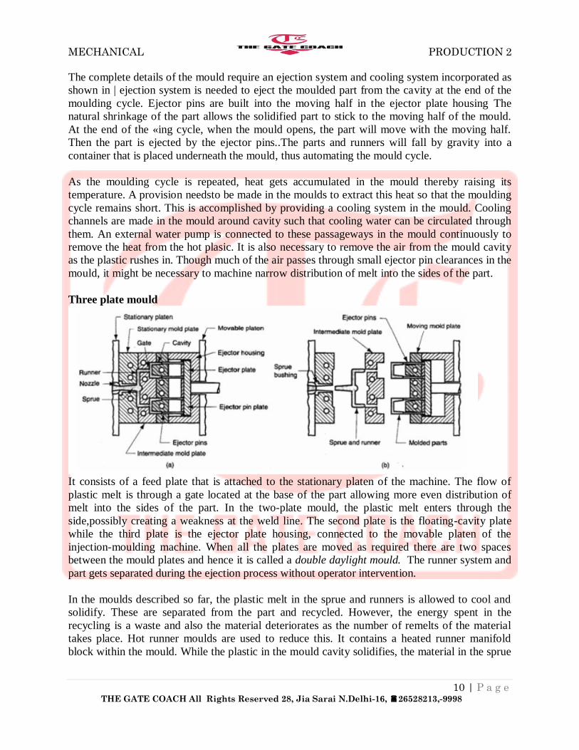
Three plate mould
It consists of a feed plate that is attached to the stationary platen of the machine. The flow of
plastic melt is through a gate located at the base of the part allowing more even distribution of
melt into the sides of the part. In the two-plate mould, the plastic melt enters through the
side,possibly creating a weakness at the weld line. The second plate is the floating-cavity plate
while the third plate is the ejector plate housing, connected to the movable platen of the
injection-moulding machine. When all the plates are moved as required there are two spaces
between the mould plates and hence it is called a double daylight mould. The runner system and
part gets separated during the ejection process without operator intervention.
In the moulds described so far, the plastic melt in the sprue and runners is allowed to cool and
solidify. These are separated from the part and recycled. However, the energy spent in the
recycling is a waste and also the material deteriorates as the number of remelts of the material
takes place. Hot runner moulds are used to reduce this. It contains a heated runner manifold
block within the mould. While the plastic in the mould cavity solidifies, the material in the sprue

MECHANICAL PRODUCTION 2
11 | P a g e THE GATE COACH All Rights Reserved 28, Jia Sarai N.Delhi-16, 26528213,-9998
and runner channels remains molten, ready to be injected into the cavity in the next mould cycle.
Hot runner moulds reduce the overall cost by reducing the recycling of sprues and runners.
REACTION INJECTION MOULDING
Reaction injection moulding is the process used for moulding thermosetting materials such as
polyurethane and epoxy, which exist in liquid form before they polymerize.. The two
components that form the urethane are stored in the two tanks and the appropriate amounts of the
individual liquids will be mixed in the mixing head. This mixture of two components in the
proper chemical ratio is delivered into the mould at low pressure, where it polymerizes, cross-
links and forms the part. Typically, this low-temperature process takes less than a minute to
complete including mixing, curing and demoulding.
Depending on how the polyurethane RIM system is formulated, the parts moulded with it can be
foam or a solid, and they can vary from being flexible to extremely rigid. Thus, polyurethane
RIM processing can produce virtually anything from a very flexible foam-core part to a rigid
solid part with specific gravities ranging from 0.2 to 1.6. Th^process was originally developed to
mould very large automobile parts such as bumpers, interior trim panels and spoilers. Because of
the low pressures used, the cost of the mould is much less compared to the conventional injection
moulding.
LIQUID INJECTION MOULDING
Liquid injection moulding is used for moulding silicone products. In this process, pumping
systems deliver a two-part liquid silicone (catalyst and cross linker) directly into a mixer for
homogenization. This mix is then injected directly into heated mould cavities in as little as 3 to
10 seconds using a relatively low pressure. Moulding and vulcanization (curing) occur inside the
mould cavities within 10 to 90 seconds due to the high mould temperature. The entire processing
takes place within a completely closed system ensuring. The mam advantages of this process are
the following:

MECHANICAL PRODUCTION 2
12 | P a g e THE GATE COACH All Rights Reserved 28, Jia Sarai N.Delhi-16, 26528213,-9998
1. Automated process with completely integrated processing. This ensures cleanliness with
minimized contamination risk.
2. The injection pressures used are low which means it requires less clamping force for the
moulds. Faster cycle times with consistent part quality.
CO-INJECTION MOULDING
This is a process that uses two materials to mould a part. The two materials have different
materials with one being hard that forms the skin, while the softer one forms the core through the
injection-moulding process. It requires two injection units for the two different plastics being
used. The skin material is injected first into the mould cavity, and is immediately followed by a
core material. As the skin material flows into the cavity, the material next to the cavity walls
freezes and when the core material enters, it displaces the skin material in the centre of the
channel by pushing the skin ahead. As the skin material flows ahead, it continues to freeze on the
walls producing the skin layer.
Typical applications of this process are the following:
1. The core can be a foam to reduce the weight of the part and at the same time absorb
noise.
2. Cores can be glass filled to get improved mechanical properties.
3. It is environment friendly since recycled material can be embedded as core without
worrying about the appearance of the part. Glass-filled cores can be used for improved
physical properties.
4. High-gloss skin material over structural core material is used for combination of aesthetic
and structural properties
BLOW MOULDING
Blow moulding is the process of inflating a hot, hollow, thermoplastic preform or parison inside
a closed mould so that its shape conforms to that of the mould cavity. A wide variety of hollow
parts, including plastic bottles, can be produced from many different thermoplastic materials
using this process.
The cost of blow-moulded parts is higher than that of injection-moulded parts, but lower than
rotational-Moulded parts. Tooling costs are lower compared to injection moulding. The cycle
times are relatively higher compared to injection moulding because of the process involved.
Typical parts made are bottles, toys, air duets for automobiles, chemical and gasoline tanks, and
a number of household goods.

MECHANICAL PRODUCTION 2
13 | P a g e THE GATE COACH All Rights Reserved 28, Jia Sarai N.Delhi-16, 26528213,-9998
ExtrusionBlow Moulding Extrusion blow-moulding machine consists of an extruder similar to that used with plastic
extrusion, which the plastic and forms it into a tube (called a parison or preform) through a
conventional-type die and a split-body mould. The die closes around the parison, sealing both
ends. A blow pin is inserted into the parison to inflate it, causing it to expand and confirm the
shape of mould cavity. Again, the mould is cooled and once the part has solidified, the mould
opens the part is removed Extrusion blow-moulding is a continuous process that is used mostly
manufacture small, thin-walled parts but can produce parts such as large drums.
Extrusion blow moulding can be used for a wide variety of container shapes, sizes and neck
openings. These machines are very fast and often can produce 300 to 350 bottles per hour.
Extrusion blow moulds are generally much less expensive than injection blow moulds and can be
produced in a much shorter period of time. This process can use many different plastics,
including HDPE, PVC, PC, and PP. The capital investment required for extrusion blow
moulding is low and is suitable for small production runs. Some disadvantages usually include a
high scrap rate, a limited control over wall thickness, and some difficulty of trimming away
excess plasti
In the blow moulds, coolant flow channels are provided to accelerate part cooling thereby
reducing the cycle time. Also, there are raised regions on the die face to pinch off and seal the
parison before blowing. Sometimes recessed regions are provided for the flash-to flow into
thereby minimizing the potential for mould separation due to flashing. Vents may also be
provided which are small channels at the mould wall end, to allow air to escape from between
the part wall and mould surface.
Mould-material strength is not an important criterion as blow-moulding pressures are relatively
low compared to other moulding operations. The majority of moulds are made from high-
strength aluminium alloys. However, mould wear may become a problem. Plated steel and
beryllium—copper are alternative materials for moulds or these more wear-resistant materials
that can be used for various components of aluminium moulds, e.g., inserts and pinch-offs.
Extrusion blow moulding is usually used to make items of weight greater than 350 g such as
containers for food, laundry, or waste
INJECTION BLOW MOULDING

MECHANICAL PRODUCTION 2
14 | P a g e THE GATE COACH All Rights Reserved 28, Jia Sarai N.Delhi-16, 26528213,-9998
Injection blow moulding is a two-stage process with the parison being produced in the first stage
which needs to be transferred to the blow mould. Thus, the first operation is identical to the
injection moulding described earlier. The plastic melt is injected into a heated preform mould
around a hollow mandrel blow tube or core rod. The workpiece for the second stage in the blow-
moulding process is the parison and the blow rod assembly. This assembly is then transferred to
the blow mould, and the mould is closed around it.
Between the preform production and the blow d preform may be held in a temperature-
conditioning stage or a cooled preform is re-heated. If the jnould is provided with cooling
channels, the coolant may be heated to a temperature lower than the melt temperature but high
enough so that the preform can be directly transferred to the blowing station wttb pie,-
temperature conditioning. Air is introduced through the mandrel to inflate the part to conform to
the internal cavity of the mould.The air is injected into the plastic at a pressure Jjjn 0.50 to 1.0
MPa. Once cooled, the mould opens, and the part is indexed to the ejection part of the machine
where the finished part is removed from the mandrel.
Injection blow moulding is used to achieve very accurate wall thickness, high-quality neck
finish, wide mouth openings and to process polymers that cannot be extruded. Generally, an
injection blow-moulded container's material is distributed evenly throughout, and does not need
any trimming or reaming. It is suitable for smaller containers. Injection blown containers usually
have a set gram weight which cannot be changed unless a whole new set of blow stems are built.
The usual applications include pharmaceutical, cosmetic, single-serving liquor bottles that weigh
less than 350 g.
STRETCH BLOW MOULDING
Stretch blow moulding is best known for producing PET bottles commonly used for water, juice
and a variety of other products. It produces a part with the required properties for the work
material by producing desirable molecular orientation. In this process, a preform or parison is
elongated mechanically in the mould and then expanded radially in the blowing process. As a
result, the desirable resulting molecular orientation yields Imaterial with increased strength. This
biaxial stretching of material increases the tensile strength, barrier properties, drop impact,
clarity, and top load in the container. With these increases, it is usually possible to reduce the
overall weight in a container by 10 to 15 per cent less than when producing a container by
simpler blow-moulding techniques. Stretch blow moulding is only used for difficult-to-blow
crystalline and crystal-lizable polymers such as polypropylene and polyethylene terephthalate
(PET).
In order to produce and retain the desired structure and specified properties, the stretching and
blowing proc-ineed to be carried out at a temperature lower than in other blow-moulding
processes. Thus, the allowable |§e for this will be smaller and hence is more difficult to control. A
temperature conditioning
Stretching blow moulding starts the production of a preform similar to the injection blow-
moulding process. The parision and the blow rod assembly is then transferred to the blow mould,
and the mould is closed around it.The preform is reheated before it is placed in the bottle mould.
MECHANICAL PRODUCTION 2
15 | P a g e THE GATE COACH All Rights Reserved 28, Jia Sarai N.Delhi-16, 26528213,-9998
The softened parison is stretched to about twice its original length .Compressed air is then blown
into the Stretched parison to expand to the contours of the mould .Once the bottle is cooled, the
mould is opened and the finished bottle is removed from the mould cavity.
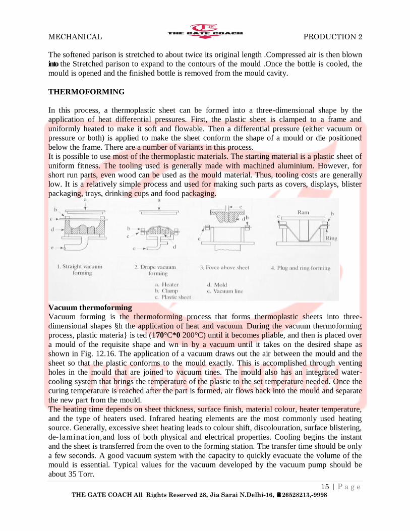
THERMOFORMING
In this process, a thermoplastic sheet can be formed into a three-dimensional shape by the
application of heat differential pressures. First, the plastic sheet is clamped to a frame and
uniformly heated to make it soft and flowable. Then a differential pressure (either vacuum or
pressure or both) is applied to make the sheet conform the shape of a mould or die positioned
below the frame. There are a number of variants in this process.
It is possible to use most of the thermoplastic materials. The starting material is a plastic sheet of
uniform fitness. The tooling used is generally made with machined aluminium. However, for
short run parts, even wood can be used as the mould material. Thus, tooling costs are generally
low. It is a relatively simple process and used for making such parts as covers, displays, blister
packaging, trays, drinking cups and food packaging.
Vacuum thermoforming
Vacuum forming is the thermoforming process that forms thermoplastic sheets into three-
dimensional shapes §h the application of heat and vacuum. During the vacuum thermoforming
process, plastic materia} is ted (170°C*0 200°C) until it becomes pliable, and then is placed over
a mould of the requisite shape and wn in by a vacuum until it takes on the desired shape as
shown in Fig. 12.16. The application of a vacuum draws out the air between the mould and the
sheet so that the plastic conforms to the mould exactly. This is accomplished through venting
holes in the mould that are joined to vacuum tines. The mould also has an integrated water-
cooling system that brings the temperature of the plastic to the set temperature needed. Once the
curing temperature is reached after the part is formed, air flows back into the mould and separate
the new part from the mould.
The heating time depends on sheet thickness, surface finish, material colour, heater temperature,
and the type of heaters used. Infrared heating elements are the most commonly used heating
source. Generally, excessive sheet heating leads to colour shift, discolouration, surface blistering,
de- laminat ion,and loss of both physical and electrical properties. Cooling begins the instant
and the sheet is transferred from the oven to the forming station. The transfer time should be only
a few seconds. A good vacuum system with the capacity to quickly evacuate the volume of the
mould is essential. Typical values for the vacuum developed by the vacuum pump should be
about 35 Torr.

MECHANICAL PRODUCTION 2
16 | P a g e THE GATE COACH All Rights Reserved 28, Jia Sarai N.Delhi-16, 26528213,-9998
Pressure Thermoforming
Pressure thermoforming is an improvement over vacuum forming, in that it utilizet both vacuum
and com- air to force the plastic sheet against the mould. As the platens are closed, the vacuum
pulls on one side of the sheet against the mould and Compressed air pushes on the other.
Reasonably high Jpsttres approaching 3.5 MPa are used for forming the requisite shapes. This
compressed air pressure reduces the cycle time and makes it possible to run at lower
temperatures. It also improves the distribution of the material creating a more even wall
thickness and enhances the detail of the part to a nearly injection-moulded quality. The increased
air pressure will require a stronger mould and a locking device for the platens. After the part has
been formed, the platens unlock and one of the platens moves out of the way to speed up the
cooling process.
This process is mainly used for parts that require styling and aesthetic qualities because pressure
forming creates greater detail, allowing for textured surfaces, undercuts and sharp corners, which
are not as easily created with vacuum forming.
Drape Forming The moulds shown in the two processes are called negative (female) moulds. Since the part is
drawn towards the negative mould, the exterior of the part will have the exact surface detail that
is present on the mould surface. The interior side will be an approximation of the same. The
problem with the negative moulds is that forcing the material to follow the negative contours is
more difficult. This is termed drape forming.

MECHANICAL PRODUCTION 2
17 | P a g e THE GATE COACH All Rights Reserved 28, Jia Sarai N.Delhi-16, 26528213,-9998
Positive moulds are easier to build and generally cost less than negative moulds. However,
positive moulds can be easily damaged. Drape forming can also be used with gravitational force
alone. For multi-cavity forming, such as tote trays female moulds are preferred because they do
not require as much spacing as male moulds.
There are many variants of thermoforming processes such as plug assist forming, vacuum-snap
back, bil» tew forming, stretch forming, matched die forming, and twin-sheet forming.
THERMOSETTING MATERIALS
Unlike the thermoplastic materials, thermosetting materials cannot be remelted once
polymerization takes place. Hence, resin compounds of thermosetting materials need to be
formed before the polymerization process. As a result, the processes used for thermosetting
materials are different from those of thermoplastic materials that were discussed so far. The
mould used for these materials should be able to provide the conditions for polymerization
within the moulding machine. Generally, heat and pressure are the two variables that are
permitted to vary during the polymerization process. RIM discussed earlier for thermosetting
materials (epoxy and urethane) do not require heat or high pressure for polymerization.
Compression Moulding
Compression moulding is the oldest plastic-processing method. A compression mould is made of
two halves with one each being connected to the platens of the press. The mould is electrically
heated to maintain the required temperature. Material is placed in the mould, and it is closed with
a hydraulic cylinder, or toggle .The pressure maintained on the material is of the order of 14 to
40 MPa of moulding area. As the material comes in contact with the heated mould surface, it
softens and fills the entire cavity and at the same time initiates the chemical reaction which cures
the part. Cure time is determined by the thickest cross section, mould temperature, material type
and grade. After curing, the mould opens and the part is ejected.The most widely used plastic is
phenol-formaldehyde, commonly known as 'Bakelite'.
The compression moulds are simple and the tooling costs are relatively low. Most of the material
in the mould is utilized with very little waste products. The stability and the dimensional
accuracy that can be achieved are good. Since the moulding pressures required are low, ft ii
possible to mould large parts with relatively small presses. The process is good for large parts.
Shrinkage is minimized and closely reproducible.

MECHANICAL PRODUCTION 2
18 | P a g e THE GATE COACH All Rights Reserved 28, Jia Sarai N.Delhi-16, 26528213,-9998
In spite of the many advantages of the processes, there are certain limitations which need to be
considered while planning this process. The charge placed in the mould needs to be tightly
controlled. The depth of the part is limited because of the necessity to maintain the rigidity of the
punch. Often it is limited to 2 to 3 times the diameter of the punch. Mould design gets tougher
for complex part geometries, particularly with uneven parting lines
Transfer Moulding
Transfer moulding is very similar to compression moulding and is developed to avoid the
disadvantages found in that process. In this method, thermosetting charge is heated and
compressed in a separate chamber and then injected into the closed mould where it is allowed to
cool and solidify. Transfer moulding it capable of moulding part shapes that are more intricate
than compression moulding but not lion moulding
In transfer moulding, the thermosetting charge is loaded into a transfer pot immediately above
the mould cavity. Here, the charge is heated and pressure is applied to force the softened polymer
to flow into the heated mould where curing takes place. Curing time required intransfer
moulding is less than that required for the compression moulding. After the curing, the transfer
ram is retracted while the moulded part is ejected from the mould. The sprue and theleftover
metal with the ram called cull are scrap and need to be discarded since they cannot be recycled.
Transfer moulding also lends itself to moulding with inserts, in which a metal or ceramic insert is
placed ' fflto cSidty prior to injection and the heated plastic bonds to the insert during moulding.
Since the mould is closed before the plasticjis injected, the time taken for injection takes less
time. It is possible to have longer core pinssince they can be supported at both ends. Tool
maintenance is relatively low because of the smaller pressures involved. However, it generates
waste material in the form of cull and sprue. Compared to compression moulding, high moulding
pressures are required for the transfer process, so fewer cavities can can be putinto a press of the
same capacity