PRODUCTION SYSTEM FOR BAMBOO BICYCLES · 1 ABSTRACT The Bamboo Bike Project is a non-profit...
67
Project Number: ME-CAB-0429 PRODUCTION SYSTEM FOR BAMBOO BICYCLES A Major Qualifying Project Report Submitted to the Faculty of the WORCESTER POLYTECHNIC INSTITUTE in partial fulfillment of the requirements for the Degree of Bachelor of Science in Mechanical Engineering by Kirk H. Dragsbaek _________________________________________ Jack N. Sandgren _________________________________________ Becky Yang _________________________________________ Date: April 30 th , 2011 Approved: _________________________________________ Prof. Christopher A. Brown, Advisor
Transcript of PRODUCTION SYSTEM FOR BAMBOO BICYCLES · 1 ABSTRACT The Bamboo Bike Project is a non-profit...
Project Number: ME-CAB-0429
PRODUCTION SYSTEM FOR BAMBOO BICYCLES
A Major Qualifying Project Report
Submitted to the Faculty
of the
WORCESTER POLYTECHNIC INSTITUTE
in partial fulfillment of the requirements for the
Degree of Bachelor of Science
in Mechanical Engineering
by
Kirk H. Dragsbaek _________________________________________
Jack N. Sandgren _________________________________________
Becky Yang _________________________________________
Date: April 30th, 2011
Approved:
_________________________________________
Prof. Christopher A. Brown, Advisor
1
ABSTRACT
The Bamboo Bike Project is a non-profit organization that aims to implement bicycles made of
bamboo as a sustainable form of transportation in rural areas of Ghana and other third world African
countries. They hope to fulfill local needs by setting up a systematic bamboo cargo bicycle building
training and fueling a bicycle building industry. Our project focused on designing more efficient methods
to conduct specific production processes for building bamboo bicycles. The two main areas of
concentration were in boring holes in bamboo shafts and streamlining the bicycle frame assembly by
modifying the current joint design. A self-centering hole boring V-block component that can be attached
to a table of a drill press was designed and manufactured. Several concepts for the joint design were
developed and analyzed for their benefits and shortcomings.
2
ACKNOWLEDGEMENTS
We would like to extend our most sincere thanks to the following people, as these people were
instrumental in the successful completion of our project. We would like to thank Christopher A. Brown
for his guidance and advice throughout the entire project; Torbjorn S. Bergstrom and Adam Sears for
their patience, support, and sharing their extensive knowledge to help us gain experience with
machining during the building of our prototypes. We would also like to thank Haas Automation Inc., DP
Technology (Esprit) and Axiomatic Design Solutions Inc. (Acclaro DFSS). These companies’ generous
donations to WPI made it possible to complete our project.

3
TABLE OF CONTENTS
ABSTRACT ........................................................................................................................ 0
ACKNOWLEDGEMENTS .................................................................................................... 2
LIST OF FIGURES ............................................................................................................... 6
LIST OF TABLES ................................................................................................................ 7
1. Introduction ............................................................................................................ 8
1.1. Objective .....................................................................................................................8
1.2. Rationale .....................................................................................................................8
1.3. State of the Art ............................................................................................................9
1.3.1. Hole Boring State of the Art .............................................................................................. 9
1.3.2. Joint Design State of the Art ............................................................................................. 9
1.4. Approach ................................................................................................................... 10
1.4.1. Hole Boring Approach ..................................................................................................... 10
1.4.2. Joint Design Approach .................................................................................................... 10
2. Hole Boring System ................................................................................................ 11
2.1. Design Decomposition and Constraints ....................................................................... 11
2.1.1. Upper Level Decomposition ............................................................................................ 11
2.1.1.1. Functional Requirements ........................................................................................................ 11
2.1.1.2. Design Parameters .................................................................................................................. 11
2.1.1.3. Process Variables .................................................................................................................... 12
2.1.2. Decomposition of Functional Requirement 2 ................................................................. 13
2.1.2.1. Functional Requirements ........................................................................................................ 13
2.1.2.2. Design Parameters .................................................................................................................. 14
4
2.1.3. Decomposition of Functional Requirement 3 ................................................................. 15
2.1.3.1. Functional Requirements ........................................................................................................ 15
2.1.3.2. Design Parameters .................................................................................................................. 16
2.1.4. Decomposition of Functional Requirement 4 ................................................................. 16
2.1.4.1. Functional Requirements ........................................................................................................ 17
2.1.4.2. Design Parameters .................................................................................................................. 17
2.2. Physical Integration ................................................................................................... 19
2.2.1. Design Parameters and Functional Requirements ......................................................... 19
2.2.1.1. Components ............................................................................................................................ 19
2.2.1.2. Compatibility Matrix ............................................................................................................... 23
2.2.2. Finite Element Analysis ................................................................................................... 25
2.2.3. Tolerancing ...................................................................................................................... 26
2.3. Prototype Production ................................................................................................. 27
2.3.1. Machining of the Hole Boring Component ..................................................................... 27
2.3.1.1. Stock Selection ........................................................................................................................ 27
2.3.1.2. Fixturing of the Stock .............................................................................................................. 28
2.3.1.3. Tool Selection .......................................................................................................................... 28
2.3.1.4. Machining Methods ................................................................................................................ 29
2.3.1.5. Errors ....................................................................................................................................... 30
2.3.2. Dimension Comparisons Between CAD Model and Prototype ....................................... 33
2.3.3. Machined Parts Assembly ............................................................................................... 34
2.4. First Prototype ........................................................................................................... 35
2.5. Discussion .................................................................................................................. 36
2.6. Conclusions ............................................................................................................... 39
3. Joint Design ........................................................................................................... 40

5
3.1. Design Decomposition and Constraints ....................................................................... 40
3.1.1. Upper Level Decomposition ............................................................................................ 40
3.1.1.1. Functional Requirements ........................................................................................................ 40
3.1.1.2. Design Parameters .................................................................................................................. 40
3.1.1.3. Process Variables .................................................................................................................... 41
3.1.2. Lower Level Decomposition ............................................................................................ 42
3.1.2.1. Functional Requirements ........................................................................................................ 42
3.1.2.2. Design Parameters .................................................................................................................. 43
3.2. Physical Integration ................................................................................................... 44
3.2.1. Design Parameters and Functional Requirements ......................................................... 44
3.2.1.1. Critical Surfaces of Seat Joint .................................................................................................. 44
3.2.1.2. Compatibility Matrix ............................................................................................................... 45
3.2.2. Finite Element Analysis ................................................................................................... 46
3.3. Discussion .................................................................................................................. 50
3.4. Conclusions ............................................................................................................... 52
4. References ............................................................................................................. 53
5. Appendices ............................................................................................................ 54
A. Documentation of Current Methods............................................................................... 54
B. Full Decomposition of Hole Boring System ..................................................................... 56
C. Iterations of Hole Boring System .................................................................................... 57
D. CNC Machining Documentation ..................................................................................... 64
E. Full Decomposition of Joint Design ................................................................................. 66

6
LIST OF FIGURES
Figure 1: Critical surfaces of assembly ................................................................................................. 19
Figure 2: Aluminum base ...................................................................................................................... 20
Figure 3: V-block ................................................................................................................................... 21
Figure 4: Brass rod ................................................................................................................................ 22
Figure 5: Aluminum wall ....................................................................................................................... 23
Figure 6: Compatibility matrix for hole boring system ......................................................................... 24
Figure 7: FEA of v-block component ..................................................................................................... 26
Figure 8: Bike frame diagram ............................................................................................................... 41
Figure 9: Labeled critical surfaces of seat joint .................................................................................... 44
Figure 10: Compatibility matrix for joint design ................................................................................... 45
Figure 11: FEA of rear joint ................................................................................................................... 46
Figure 12: FEA of seat joint ................................................................................................................... 47
Figure 13: FEA of pedal joint ................................................................................................................ 48
Figure 14: FEA of handle joint .............................................................................................................. 49
Figure 15: Full decomposition of hole boring system .......................................................................... 56
Figure 16: First iteration ....................................................................................................................... 57
Figure 17: Second iteration .................................................................................................................. 58
Figure 18: Third iteration ...................................................................................................................... 60
Figure 19: Fourth iteration ................................................................................................................... 61
Figure 20: Fifth iteration ....................................................................................................................... 62
Figure 21: Sixth iteration ...................................................................................................................... 63
Figure 22: Full decomposition of joint design ...................................................................................... 66
7
LIST OF TABLES
Table 1: Upper level decomposition of hole boring system ................................................................. 11
Table 2: Decomposition of FR2 in hole boring system ......................................................................... 13
Table 3: Decomposition of FR3 in hole boring system ......................................................................... 15
Table 4: Decomposition of FR4 in hole boring system ......................................................................... 17
Table 5: Comparison between theoretical and actual dimensions ...................................................... 33
Table 6: Upper level decomposition of joint design ............................................................................. 40
Table 7: Decomposition of seat post joint ........................................................................................... 42
8
1. Introduction
1.1. Objective
The objective of this project is to design more efficient methods to conduct specific production
processes for creating a bamboo bicycle.
1.2. Rationale
The Bamboo Bike Project, a non-profit organization, aims to implement bicycles made of
bamboo as a sustainable form of transportation in sub-Saharan Africa, as many people living there have
no other means of in-expensive transportation. Manufacturing the bamboo bicycles in Africa lowers
the cost of the bicycle more, as well as provides employment for the locals. The process that is
currently in the process of being implemented works, but there are always improvements that can
be made. Focusing on improving upon specifics aspects of the bamboo bicycle production process is
important, as it can result in safer manufacturing and more efficient manufacturing process and
improved quality and lifespan of the product.
The current process to bore a hole in the seat tube is both dangerous and inaccurate. One hand
is used to hold the seat tube while the other hand uses a hand drill and forces the tool down the tube.
Resistance is felt both when drilling and withdrawing the drill. Finding a new method is important, as it
can eliminate potential accidents from happening when using the hand drill as well as eliminate the
inaccuracy while implementing consistency.
The joints are secured using a combination of carbon fiber tape and epoxy, which results in a
high density, high strength material complex. The current method works in the way that the person can
tension the joints in place and self-compress while wrapping. However, for a person doing the wrapping
for the first time, the process can take 7 to 8 hours. Even for someone experienced in the process, it can
take approximately 40 minutes. The carbon fiber is unidirectional, so the pattern one wraps the joints is

9
critical to their strength; the strength can be drastically affected if the pattern is not wrapped correctly.
Changing this current method can be beneficial for many reasons. It can decrease the time of the
process, as well as simplify the process. Simplifying the process can help simplify the training to teach
local Africans and reduce the total time it takes to make a bicycle.
1.3. State of the Art
1.3.1. Hole Boring State of the Art
The current method for boring the hole in the seat post tube is dangerous and does not provide
consistent results. The bamboo shaft is constrained by hand. This method means that the force of the
drill can easily cause movement in the shaft and that there is no standard for how the bamboo is
positioned. This movement could cause harm to the person doing the drilling in addition to inaccuracies
in the drilling process. The drilling is also done by hand. Further inaccuracies are caused by this. The
hole is not guaranteed to be straight or centered in the right place. The hole may also be drilled at a
slight angle.
1.3.2. Joint Design State of the Art
The joints on the bike frame are made using a tedious and time consuming process that can be
difficult to teach. The bike frame elements are held in place using a jig designed for the bike making
process. While they are being held in place the bike elements are tacked together using hot glue just to
hold the shape. The next step is to encase the joint in an epoxy. Following this carbon fiber is wrapped
around the partially hardened epoxy with emphasis on tight wrapping to the point that some of the
epoxy is squeezed out. This step provides the strength in the joint. The final step is to wrap the entire

10
joint in electrical tape again with an emphasis on making sure the wrap is very tight. This last step
ensures that the joint stays together.
1.4. Approach
1.4.1. Hole Boring Approach
As mentioned in the state-of-the-art section, the current method of boring holes in bamboo
shafts is inefficient and potentially dangerous. By implementing axiomatic design, the group developed
a design that will make the process safer and more efficient. The use of axiomatic design allowed the
group to arrive at a final product that will satisfy the requirements of the system. An ideal solution was
determined and then parts were modeled using SolidWorks. These parts were then analyzed using
finite element analysis in SolidWorks. To machine the parts, the computer-aided manufacturing
software program Esprit was used in combination with Haas CNC mini mills as well as other machines.
1.4.2. Joint Design Approach
The main issue with the current method of assembling bamboo bicycle frames is that it is very
tedious and time consuming. The aim of this project is to streamline the process by using axiomatic
design. The functional requirements were determined and corresponding design parameters were
defined in order to ensure that all requirements were met. SolidWorks was utilized to create three-
dimensional models of the parts. The SolidWorks models were sent to the rapid prototyping machine
facility to acquire physical products for further examination. The different concepts for a joint design
system were analyzed for their benefits and limitations.
11
2. Hole Boring System
2.1. Design Decomposition and Constraints
For a visual of the full decomposition, see Appendix A.
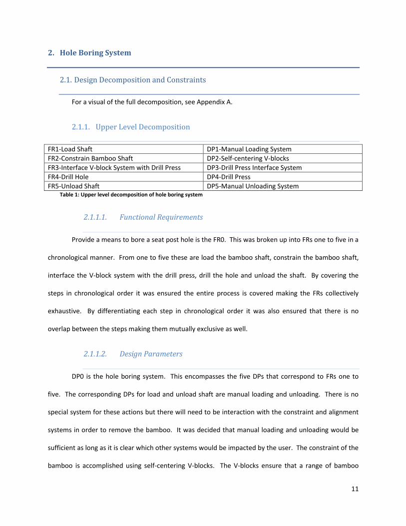
2.1.1. Upper Level Decomposition
FR1-Load Shaft DP1-Manual Loading System
FR2-Constrain Bamboo Shaft DP2-Self-centering V-blocks
FR3-Interface V-block System with Drill Press DP3-Drill Press Interface System
FR4-Drill Hole DP4-Drill Press
FR5-Unload Shaft DP5-Manual Unloading System Table 1: Upper level decomposition of hole boring system
2.1.1.1. Functional Requirements
Provide a means to bore a seat post hole is the FR0. This was broken up into FRs one to five in a
chronological manner. From one to five these are load the bamboo shaft, constrain the bamboo shaft,
interface the V-block system with the drill press, drill the hole and unload the shaft. By covering the
steps in chronological order it was ensured the entire process is covered making the FRs collectively
exhaustive. By differentiating each step in chronological order it was also ensured that there is no
overlap between the steps making them mutually exclusive as well.
2.1.1.2. Design Parameters
DP0 is the hole boring system. This encompasses the five DPs that correspond to FRs one to
five. The corresponding DPs for load and unload shaft are manual loading and unloading. There is no
special system for these actions but there will need to be interaction with the constraint and alignment
systems in order to remove the bamboo. It was decided that manual loading and unloading would be
sufficient as long as it is clear which other systems would be impacted by the user. The constraint of the
bamboo is accomplished using self-centering V-blocks. The V-blocks ensure that a range of bamboo
12
diameters can be accommodated. The V-blocks were also designed to be self-centering which reduces
the difficulty in aligning the bamboo shaft with the drill press and ensures the center of the bamboo
lines up with the center of the drill bit regardless of bamboo diameter. In order to interface the V-block
system with the drill press and satisfy FR 3 a drill press interface system was designed. This includes
parts to align the bamboo with the drill press and ensure the system is attached securely. The details on
what is included in this system are discussed in the continued decomposition of FR3.
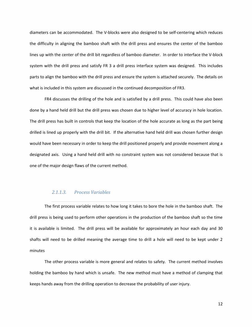
FR4 discusses the drilling of the hole and is satisfied by a drill press. This could have also been
done by a hand held drill but the drill press was chosen due to higher level of accuracy in hole location.
The drill press has built in controls that keep the location of the hole accurate as long as the part being
drilled is lined up properly with the drill bit. If the alternative hand held drill was chosen further design
would have been necessary in order to keep the drill positioned properly and provide movement along a
designated axis. Using a hand held drill with no constraint system was not considered because that is
one of the major design flaws of the current method.
2.1.1.3. Process Variables
The first process variable relates to how long it takes to bore the hole in the bamboo shaft. The
drill press is being used to perform other operations in the production of the bamboo shaft so the time
it is available is limited. The drill press will be available for approximately an hour each day and 30
shafts will need to be drilled meaning the average time to drill a hole will need to be kept under 2
minutes
The other process variable is more general and relates to safety. The current method involves
holding the bamboo by hand which is unsafe. The new method must have a method of clamping that
keeps hands away from the drilling operation to decrease the probability of user injury.

13
2.1.2. Decomposition of Functional Requirement 2
FR2.1-Position Bamboo Shaft DP2.1-V-block System Surfaces
FR2.1.1-Position Top End in Y,Z Plane DP2.1.1-Top Self-centering V-block
FR2.1.2-Position Bottom End in Y,Z Plane DP2.1.2-Bottom Self–centering V-block
FR2.1.3- Position Along X-axis DP2.1.3-Base of V-block system
FR2.2-Resist Forces on Bamboo Shaft DP2.2-V-block Reaction Forces
FR2.2.1-Resist Moments about Z-axis DP2.2.1-V-block Z-components
FR2.2.2-Resist Moments about Y-axis DP2.2.2-V-blocky Y-components
FR2.2.3-Resist Moments about X-axis DP2.2.3-Frictional Force of Rubber Material
FR2.2.4-Resist Translation along X-axis DP2.2.4-Base of V-block System
FR2.2.5-Resist Translation along Y-axis DP2.2.5-Fasteners at Rod-Wall Interface
FR2.2.6-Resist Translation along Z-axis DP2.2.6-Proper Wall Hole Size Table 2: Decomposition of FR2 in hole boring system
2.1.2.1. Functional Requirements
FR2 was decomposed into the two different elements of constraint. These two elements are
position of the bamboo shaft and resisting forces on the bamboo shaft. These are the two necessary
elements of most constraint problem. If these two elements are satisfied the bamboo shaft will be fully
constrained.
The positioning of the bamboo shaft is divided up into three components. The top and bottom
of the shaft both must both be positioned in the Y,Z plane. Ensuring that the top and bottom are
positioned properly ensures that the bamboo is not angled. The shaft must also be positioned along the
X-axis which is the axis that runs through the hollow center of the bamboo shaft. This constraint
guarantees the top edge of the bamboo will be at a consistent location making drilling easier.
Positioning the bamboo shaft properly with respect to those three constraints will ensure position is
fully constrained with the minimum number of requirements.
There are six forces that must be resisted on the bamboo shaft to keep it from moving.
Moments about all three axes must be resisted to keep the shaft from twisting in any direction.

14
Moments not resisted about the X-axis would cause the drilling operation to be ineffectual. Moments
about the Y or Z-axis would shift the X-axis away from the drilling axis causing the hole to be angled. The
shaft must also be kept from moving along any of the three axes. Translation along the X-axis would
result in the depth of the hole being affected or an inability to drill the hole. If translation forces aren’t
resisted in the Y or Z-direction the location of the hole would be affected adversely.
2.1.2.2. Design Parameters
Functional requirement 2 is satisfied by the self-centering V-block system. The bamboo shaft is
positioned by the surfaces of the V-block system. The top and bottom ends of the bamboo shaft are
positioned in the Y,Z plane by the top and bottom V-blocks respectively. These effectively position the
bamboo because the shape of the V-block ensures the bamboo is centered within the clamps regardless
of diameter. The position along the X-axis is kept consistent by the base of the constraint system
because this will never move and is the easiest way to ensure a standard distance from the drill bit.
Preliminary designs had walls built into the bottom V-blocks to constrain the bamboo but the current
design was adopted to simplify the design and machining process. With only one V-block design instead
of two it was quicker to compete those parts.
In order to resist the forces on the bamboo shaft and keep it from moving, various reactionary
forces are being utilized. The reactionary forces of the inside walls of the V-blocks resist moments about
the Y and Z axes. The moments about the X-axis are resisted by frictional forces between the rubber
material on the inside of the V-block and the bamboo shaft. Translation along the X-axis is resisted by
the reactionary force from the base of the constraint system. Fasteners are attached to the brass rod
where it meets the walls to resist translation in the Y-direction. The threaded fasteners will interact
with the threads of the rod preventing the rod and thus the V-blocks from translating in the Y-direction.
Originally the rods were designed with shoulders that would butt against the walls that had a smaller
15
hole in order to prevent this translation but manufacturing of that design was more difficult. Holes
drilled into the walls are drilled to a size just big enough for the rod to thread through. The reaction
force of the hole on the rod prevents the V-blocks with the bamboo from translating in the Z-direction.
2.1.3. Decomposition of Functional Requirement 3
FR3.1-Attach Fixture to Drill Press DP3.1-Drill Constraint System
FR3.1.1-Align Fixture with Table DP3.1.1-L-Bracket Base Interface with Table
FR3.1.2-Secure Fixture to Table DP3.1.2-C-clamps
FR3.2-Align Fixture with Drill DP3.2-Drill Alignment System
FR3.2.1-Align Along X-axis DP3.2.1-L-Bracket Angle
FR3.2.2-Position on Y,Z Plane DP3.2.2-Aligment tube Table 3: Decomposition of FR3 in hole boring system
2.1.3.1. Functional Requirements
FR3 was decomposed into two lower level FRs. These were to attach the fixture to the drill
press and align the Fixture to the drill press. If these two elements are satisfied properly the V-block
system will be effectively interfaced with the drill press. The attachment ensure that the system will be
stable when the drilling operation takes place while the alignment makes sure the hole is drilled in the
proper location.
In order to attach the fixture to the drill press there were two steps deemed important. These
were to align the fixture with the drill press table and secure the fixture to the table. Aligning the fixture
to the drill press table ensures that the attachment step can be accomplished safely and with ease.
Securing the fixture to the drill press is necessary to ensure that the fixture doesn’t move during the
drilling operation.
The alignment with the drill is accomplished by aligning the fixture along the X-axis and then
positioning it in the Y,Z plane. The alignment along the X-axis is necessary to ensure a hole that goes
straight through the bamboo shaft. Y,Z plane positioning ensures the hole is in the center of the
bamboo.

16
2.1.3.2. Design Parameters
In order to attach the fixture to the drill press a drill constraint system is employed. The base of
the L-bracket works to align the fixture with the drill press. This section of the fixture lies flush on the
table insuring the V-block system is aligned properly with the drill press system before attachment
occurs In order to then secure the fixture to the table C-clamps are used. C-clamps were chosen
because they are easy to use readily available and provide sufficient force to clamp the fixture with
moderate work input.
In order to align the fixture with the drill press a drill alignment system is implemented. The first
step of this process is to align the fixture along the X-axis using the angle of the L-bracket to ensure the
fixture is perpendicular to the table. In order for this to work the L-bracket must have a 90 degree angle
and the upright portion must be bolted flush to the base of the V-block system. The second element is
an alignment tube that would run through the V-blocks and be used to ensure the drill bit aligns with
where the hole should be. The alignment tube was chosen due to its ease of use. It’s inserted once, the
drill bit is lined up with a tube the same size the hole would be and the tube is remove once the drill
press is adjusted to ensure alignment. Once it is aligned the bamboo can be drilled without realignment
as long as nothing in the system is moved. If these two elements work properly the fixture will be
properly aligned ensuring a straight, centered hole.
2.1.4. Decomposition of Functional Requirement 4
FR4.1-Constrain Drill DP4.1-Drill Constraint
FR4.2-Bore Hole DP4.2-Hole Boring System
FR4.2.1-Control hole Dimensions DP4.2.1-Dimension Control System
FR4.2.1.1-Control Depth DP4.2.1.1-Stopper
FR4.2.1.2-Control Diameter DP4.2.1.2-Proper Drill Bit
FR4.2.1-Insert Drill Into Bamboo DP4.2.1-Drill Motion
FR4.2.2.1-Maintain Linear Path DP4.2.2.1-Path Profile

17
FR4.2.2.2-Maintain Appropriate Speed DP4.2.2.2-User Speed Control Table 4: Decomposition of FR4 in hole boring system
2.1.4.1. Functional Requirements
FR4 was divided into two smaller problems. The first is to constrain the drill. This entails
ensuring the drill mechanism of the drill press is constrained along one axis so it’s possible to align the
bamboo with that axis. The second issue was boring the hole. This involves all aspects of the hole
boring process.
The hole boring FR is broken down into two lower level FRs at the next level. The first is to
control the hole dimensions. The two dimensions that need to be controlled are the depth and
diameter. The depth is important because the seat post tube needs to rest at a certain height by design.
The diameter of the hole needs to be controlled properly as well so that the seat post tube can fit in the
hole with a close fit. The other aspect of the hole boring is the actual insertion of the drill into the
bamboo. This FR is divided into two aspects. These are to maintain a linear path and maintain
appropriate speed. The linear path is necessary to ensure a straight hole. Appropriate speed is required
to make sure the bamboo isn’t damaged.
2.1.4.2. Design Parameters
The design parameters for the drilling of the hole are all satisfied by components of the drill
press. Axiomatic design was still used to decompose and assess the problem to ensure that the drill
press accomplished all of the aspects of the drilling operation deemed important. The first aspect of the
drilling, the drill constraint, is satisfied by the drill constraint system. This covers the structure of the
drill press that holds the drilling mechanism including the chuck that holds the drill bit.
The hole boring part of the drilling operation is satisfied by the hole boring system. The first
aspect of this is the dimension control system which controls the dimensions of the hole. This is divided
18
into two parts. The first is the stopper that controls the depth of the hole. This works by stopping the
drill bit after it has reached a predetermined depth. Having the proper drill bit is the other aspect of
dimension control. This controls the diameter of the hole by removing only the material it comes in
contact with. The drill insertion is controlled by the motion of the drill. The linear path aspect of this
problem is controlled by the path profile of the drill bit which is ensured to be linear by interior controls
in the drill press. The speed of the drill is maintained by user speed control.

19
2.2. Physical Integration
2.2.1. Design Parameters and Functional Requirements
Figure 1: Critical surfaces of assembly
Figure 1 shows an exploded view of the assembly. The critical surfaces are labeled to show
which functional requirements they satisfy. The only coupling that is present is the relationship
between the positioning and constraint of the bamboo shaft, which is not an issue because the goal is to
secure the bamboo shaft in a specified location. All components are made of aluminum alloy 6061
other than the rods, which are made of brass.
2.2.1.1. Components
2.2.1.1.1. Aluminum Tube

20
Figure 2: Aluminum base
The most prominent item in the assembly is the rectangular aluminum tube, referred to as the
base. It acts as the backbone of the attachment and all of the other components are attached to it or
interface with it in some way. The base is 3 inches by 5 inches with a wall thickness of 0.1875 inches,
and the length is 24 inches. An L-shaped bracket will be attached to the base in order to provide a
means for vertically aligning the base, thus aligning the entire system.

21
2.2.1.1.2. V-Blocks
Figure 3: V-block
The V-blocks are meant to secure and position the bamboo shaft. They are the only parts of the
assembly that are directly in contact with the bamboo, other than the drill bit. The V-shape was chosen
because it maximizes that amount of points of contact between the bamboo and the constraining
device, while accommodating for the 14 mm variance in shaft outer diameters. Increasing the points of
contact reduces the stress on any specific location, thus reducing the likelihood of mechanical or
frictional failure. The four V-blocks are all identical except for the threading; two of them are right-hand
threaded and the other two are left-hand threaded. This allows the pairs of oppositely threaded V-
blocks to move towards each other when interacting with a similarly threaded rod.
The V-blocks act as the design parameters corresponding to FR 2, constrain bamboo shaft, and
its lower level FRs. FR 2.1 requires that the system positions the bamboo shaft, which the V-blocks do
by clamping it in place. The inner surfaces of the V-blocks are responsible for maintaining the position
of the shaft. FR 2.2 states that the forces on the bamboo shaft must be resisted. The shaft is held in
place with respect to the Y- and Z-axes; any moments attempting to rotate the shaft will be resisted by
the inner surfaces of the V-block. Torque about the X-axis, which is the main axis of the bamboo, will

22
also be resisted by the frictional force between the compressive material on the inner surfaces and the
surface of the bamboo shaft.
2.2.1.1.3. Brass Rods
Figure 4: Brass rod
Brass was chosen for the rods because it is a relatively soft material with good frictional
properties for its interaction with the aluminum V-blocks. Its location on the galvanic table with respect
to aluminum also ensures that there will be minimal corrosion. The brass rods interact with the V-blocks
and are responsible for maintaining their motion and positioning. The rods are partially right-hand
threaded and partially left-hand threaded to accommodate the opposite threading of the V-blocks. This
allows the V-blocks to move toward each other as the rod is turned, making it a self-centering system.
The rods fulfill FR 2.2.5 by resisting forces along the Y-axis. In the proof of concept, a nut was threaded
onto the rods to keep them from moving in one direction along the Y-axis, and the other side was kept
stationary by a piece of adhesive applied to the outer wall.

23
2.2.1.1.4. Aluminum Walls
Figure 5: Aluminum wall
Four walls are bolted onto each corner of the base, aligned with the V-block and rod assemblies.
These walls are meant to fix the rods to the base while allowing them to still turn in one direction. They
interact with the rods to ensure that FR 2.2.5 is fulfilled.
2.2.1.2. Compatibility Matrix
In order to ensure that no design parameters were fully coupled, a compatibility matrix was
developed and analyzed. Full coupling would break one of the two axioms of axiomatic design and lead
to a system unlikely to successfully fulfill its main objective. Figure 6 shows the compatibility matrix.

24
Figure 6: Compatibility matrix for hole boring system
Full coupling was successfully avoided. There are some cases of partial coupling due to the
simplicity of the design but that doesn’t have a detrimental effect on the system. The surfaces of the V-
block components are responsible for both positioning and constraining the bamboo shaft in the Y,Z-
plane, but that is not a case of harmful coupling and is acceptable because the goal is to constrain the
shaft in a specified location. The drill constraint system is also responsible for two functional
requirements but that is intentional; the L-bracket attached to the base is meant to fix the system to the
drill press table while aligning it vertically. The drill press itself is involved in multiple functional
requirements but that is because it interacts with so many elements. It is used as a reference point for
alignment, used to drill the hole, and plays a role in the attachment of the system to the drill press.
25
2.2.2. Finite Element Analysis
See figure 7 for plotted Von Mises stresses on one of the V-block pieces resulting from torque.
The stress is mostly concentrated in the filleted V-shape, which is because at that junction, one of the
faces is trying to move toward the other face due to the torque force on the faces. That issue can be
resolved in an increased radius of the fillet which will spread the stress more efficiently. The entrance to
the threaded hole also makes for a slight stress concentration due to the 90 degree angle. If one were
to attempt to reduce that concentration of stress, a recommendation would be to place a countersink at
the hole to slightly round the angle.
Despite these stress concentrations, they are not predicted to cause any real problems.
Although they give us an idea of where material will break down over time, the aluminum block is not
likely to give out before the interface between the bamboo and the compressive material on the
internal faces. The frictional force of the compressive material is believed to be less than the yield
strength of aluminum alloy, therefore if any critical forces are exceeded the first issue will most likely be
the slipping of the shaft on the compressive material. The compressive foam is also presumed to be less
resilient to forces and elements than aluminum alloy, so it may end up ripping or degrading in some
way.

26
Figure 7: FEA of v-block component
2.2.3. Tolerancing
Appropriate tolerances were selected after making a CAD model of the components in order for
the components to fit together as desired. A close running fit was applied for all moving parts. From The
Machinery’s Handbook (28th edition): “Close running fits are intended chiefly for running fits on accurate
machinery with moderate surface speeds and journal pressures, where accurate location and minimum
play are desired.”1
The fit chosen for the v-blocks moving on the base is an H8f7 close running fit. For a diameter of
0.28125 inches, the handbook specified that this fit requires the hole of the v-block to be 0.0009 inches
larger. Also, for the H8f7 fit, the shaft is required to be 0.0005 inches smaller.

27
2.3. Prototype Production
2.3.1. Machining of the Hole Boring Component
After developing the SolidWorks model for the hole boring component, the parts were imported
into Esprit, a computer aided manufacturing software. Tool paths using Esprit were generated so a CNC
machine could be used to machine the parts. Based upon the tool selected, specific information for each
cut needed to be determined, including but not limited to speed and feed rates, step over, and
incremental cutting depth. These values were determined from a website that provided recommended
information from the tool manufacturer’s website for specific tools.
In the production of our hole boring component prototype, parts had to be machined using the
HAAS VF4 milling machine. Several processes were learned and used including hand-threading and
hand-tapping holes. The v-blocks were machined using the HAAS VF4 milling machine, the holes in the v-
blocks were hand tapped, the brass rods were handed threaded and the diameter at the ends were
reduced using a lathe machine, and the holes in the channel were drilled using the HAAS VF4 milling
machine. Throughout this process, we had to machine certain parts multiple times, as we encountered
errors in our machining methods. These served as learning experiences for the group, as we were all
relatively new to the machining.
2.3.1.1. Stock Selection
The v-blocks were cut from a 3 inch by 3 inch (WxH), 3.5 inch long piece of Aluminum 6061 piece
of stock. The size of the stock was bigger than the CAD dimensions of the stock and machined down to
size. This was important, because we needed all the v-blocks to be identical. The length of 3.5 inches
was chosen after careful consideration and cut using a band saw. Too long of a stock and too short of a
stock resulted in errors, as mentioned in section 4.1.4 of the report.
28
The Alloy 360 brass rod was threaded from a 9/32” diameter and 72” long piece of stock. Brass
was selected as a material after looking at a galvanic corrosion chart and confirming that brass was close
enough to aluminum on the chart to prevent corrosion from occurring. The channel used in our
component was made from an aluminum 6061 rectangular tube, 3 inch by 6 inch (HxW), 36 inches in
length, and 3/16 inches thick. The side walls were cut from a 72” long, 3” wide, 1/4” thick piece of
Aluminum 6061 piece of stock.
2.3.1.2. Fixturing of the Stock
To machine the v-block, the stock was fixture in a standard fashion using a vise and slides. To
hand tap and hand thread the v blocks and brass rods respectively, they were clamped in a table vise.
When using the drill press, a drill press vise was used to hold the side walls and base in place. The drill
press vise was secured onto the table of the drill press by using C-clamps.
2.3.1.3. Tool Selection
Drill bits used in the HAAS VF4 milling machine include a 3/8” end mill, CM .375 drill mill, I-drill,
1/4” ball end mill, and a face mill. Left handed and right handed metric M8x1.25 taps and dies were
selected to be used to fit the holes drilled in the v blocks and the brass rods. To bolt the side walls to the
base, 1/4” bolts were purchased. In order for these bolts to be usable, the appropriate drill bit was
selected to drill the holes for the bolts to go through. In this case, it was the F-drill. To drill counterbores
into the v blocks, an arbitrary drill bit was selected; the only requirement was that the diameter had to
be greater than the I-drill.
29
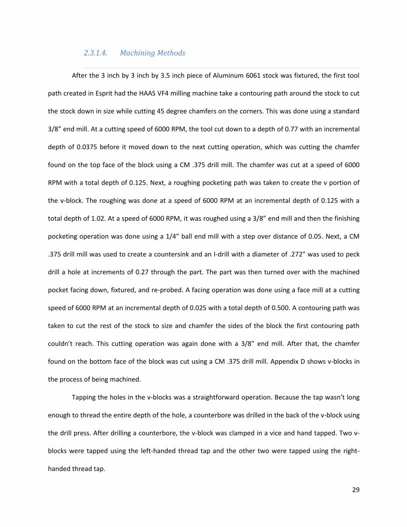
2.3.1.4. Machining Methods
After the 3 inch by 3 inch by 3.5 inch piece of Aluminum 6061 stock was fixtured, the first tool
path created in Esprit had the HAAS VF4 milling machine take a contouring path around the stock to cut
the stock down in size while cutting 45 degree chamfers on the corners. This was done using a standard
3/8” end mill. At a cutting speed of 6000 RPM, the tool cut down to a depth of 0.77 with an incremental
depth of 0.0375 before it moved down to the next cutting operation, which was cutting the chamfer
found on the top face of the block using a CM .375 drill mill. The chamfer was cut at a speed of 6000
RPM with a total depth of 0.125. Next, a roughing pocketing path was taken to create the v portion of
the v-block. The roughing was done at a speed of 6000 RPM at an incremental depth of 0.125 with a
total depth of 1.02. At a speed of 6000 RPM, it was roughed using a 3/8” end mill and then the finishing
pocketing operation was done using a 1/4” ball end mill with a step over distance of 0.05. Next, a CM
.375 drill mill was used to create a countersink and an I-drill with a diameter of .272” was used to peck
drill a hole at increments of 0.27 through the part. The part was then turned over with the machined
pocket facing down, fixtured, and re-probed. A facing operation was done using a face mill at a cutting
speed of 6000 RPM at an incremental depth of 0.025 with a total depth of 0.500. A contouring path was
taken to cut the rest of the stock to size and chamfer the sides of the block the first contouring path
couldn’t reach. This cutting operation was again done with a 3/8” end mill. After that, the chamfer
found on the bottom face of the block was cut using a CM .375 drill mill. Appendix D shows v-blocks in
the process of being machined.
Tapping the holes in the v-blocks was a straightforward operation. Because the tap wasn’t long
enough to thread the entire depth of the hole, a counterbore was drilled in the back of the v-block using
the drill press. After drilling a counterbore, the v-block was clamped in a vice and hand tapped. Two v-
blocks were tapped using the left-handed thread tap and the other two were tapped using the right-
handed thread tap.

30
The brass rods were cut down to the desired length each by clamping the rod in a vice and
sawing off the length that was needed using a band saw. The center point was measured on the rod,
and the rod was clamped vertically in a vice. From one end, the left-handed thread dye was used to
thread the rod up to the center point, and from to the other end, the right-handed thread dye was used
to thread the rod.
The side walls were cut down to the desired length by using the shear. In order for the
purchased nuts to fit properly through, we had to use the F-drill bit to drill holes into both the side walls
and the base. Each side wall had two holes through-drilled to attach to the base. The side wall was
placed against the base and a line was drawn to indicate where the top of the base comes up to the side
wall. Below that line, the center point of each sidewall piece was marked and two holes were drilled and
two holes were drilled an equal distance away from the center point. Each sidewall was matched up
with an end of the base. At each end of the base, a permanent marker was used to mark where holes on
the sidewalls were with the base. Holes were then through-drilled where the marks were made.
Through a similar procedure of lining the sidewalls up with the base, the v-blocks with the brass rod
threaded through were lined up with the side walls and the appropriate holes were through-drilled.
2.3.1.5. Errors
As previously mentioned, we encountered many errors during the process of machining parts
for our prototype. Most of our errors came from machining the four v-blocks needed for the hole boring
component.
The first error that occurred resulted in a broken 3/8” end mill. A piece of stock was cut with the
dimensions of 3 inches by 3 inches by 4.5 inches. We reasoned that a contouring operation to chamfer
the sides and cut the stock down to size was going to be done anyway, so it wasn’t necessary to risk
damaging our stock by attempting to cut the excess inch of stock off with a band saw. Unfortunately the
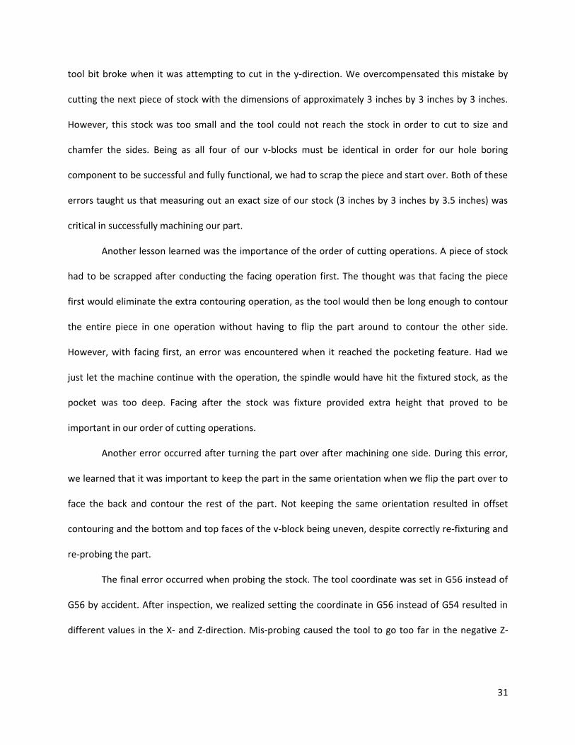
31
tool bit broke when it was attempting to cut in the y-direction. We overcompensated this mistake by
cutting the next piece of stock with the dimensions of approximately 3 inches by 3 inches by 3 inches.
However, this stock was too small and the tool could not reach the stock in order to cut to size and
chamfer the sides. Being as all four of our v-blocks must be identical in order for our hole boring
component to be successful and fully functional, we had to scrap the piece and start over. Both of these
errors taught us that measuring out an exact size of our stock (3 inches by 3 inches by 3.5 inches) was
critical in successfully machining our part.
Another lesson learned was the importance of the order of cutting operations. A piece of stock
had to be scrapped after conducting the facing operation first. The thought was that facing the piece
first would eliminate the extra contouring operation, as the tool would then be long enough to contour
the entire piece in one operation without having to flip the part around to contour the other side.
However, with facing first, an error was encountered when it reached the pocketing feature. Had we
just let the machine continue with the operation, the spindle would have hit the fixtured stock, as the
pocket was too deep. Facing after the stock was fixture provided extra height that proved to be
important in our order of cutting operations.
Another error occurred after turning the part over after machining one side. During this error,
we learned that it was important to keep the part in the same orientation when we flip the part over to
face the back and contour the rest of the part. Not keeping the same orientation resulted in offset
contouring and the bottom and top faces of the v-block being uneven, despite correctly re-fixturing and
re-probing the part.
The final error occurred when probing the stock. The tool coordinate was set in G56 instead of
G56 by accident. After inspection, we realized setting the coordinate in G56 instead of G54 resulted in
different values in the X- and Z-direction. Mis-probing caused the tool to go too far in the negative Z-

32
direction, and the 3/8” end mill tool bit snapped immediately when it was going through the first
contouring operation.
In order to form the desired shoulder on the brass rods, a lathe was used. One issue
encountered was that brass, due to its relative softness, tends to bend rather easily. Since the rod was
suspended horizontally while spinning and the cutting blade came in from the side, the rod acted as a
cantilever beam with a force on the end. The formula for deflection in a cantilever beam follows:
Equation 1: Deflection of a cantilever beam2
Since the term for length, l, is cubed, it has the largest contribution to deflection in a beam.
When machining one side of the rods, the deflection wasn’t noticeable, but when trying to machine the
longer shoulders, it became more apparent as the blade deflected the rod. Due to the deflection, the
shoulder segments had a cone-like shape. Brass also has a low modulus of elasticity making it more
malleable than other materials. The low diameter also led to a low moment of inertia to further
increase the maximum deflection.
The softness of brass went on to cause further problems in the machine shop. When threading
the rod with a die, it was clamped in a vise. However, the amount of torque required to create the
initial threads in the top of the rod caused it to twist and bend. This made it difficult if not impossible to
thread into the V-block components. To remedy this issue, the decision was made to cut the rods
oversized, thread them and then cut off the bent parts because the threads were acceptable on the rest
of the rod.
Even though the threads in the V-blocks and brass rods looked acceptable, they were not
perfect. Large amounts of force and lubrication were required to thread the rods into the V-blocks,
which posed a potential problem because the success of the design relies heavily on the ease of turning
the rod, thus moving the V-blocks toward each other. The solution to this problem was to increase the

33
depth of the counterbore in the V-blocks in order to reduce the amount of thread interaction. Since
there was less surface area in contact between the two components, they moved more freely due to the
reduction in friction.
2.3.2. Dimension Comparisons Between CAD Model and Prototype
After machining our parts, the parts were measured, and the dimensions from the machined
parts were compared to the dimensions in our CAD model. This served to find the variation and error
that occurred during machining. Table 5 below displays a comparison between the CAD dimensions and
what the actual dimensions of the prototype were.
Part Dimensions (in inches)
Part CAD Measured Percent Difference
Height from bottom of the v block 1 to hole bottom .187 .17625 5.75
Height from bottom of v block 1 to bottom of v .36 .355 1.39
Height from bottom of v block 1 to top of v 2.8 2.795 .179
V block 1, depth of v 1.023 .995 2.73
Height of v block 1 3.0 3.0125 .417
Length of v block 1 1.5 1.5125 .833
Width of v block 1 2 2.0125 .625
Height from bottom of the v block 2 to hole bottom .187 .17625 5.75
Height from bottom of v block 2 to bottom of v .36 .355 1.39
Height from bottom of v block 2 to top of v 2.8 2.795 .179
V block 2, depth of v 1.023 .995 2.73
Height from bottom of the v block 3 to hole bottom .187 .17695 5.37
Height from bottom of v block 3 to bottom of v .36 .355 1.39
Height from bottom of v block 3 to top of v 2.8 2.795 .179
V block 3, depth of v 1.023 .995 2.73
Height from bottom of the v block 4 to hole bottom .187 .17695 5.37
Height from bottom of v block 4 to bottom of v .36 .3615 .417
Height from bottom of v block 4 to top of v 2.8 2.795 .179
V block 4, depth of v 1.023 .995 2.74
Height from bottom of side wall 1 to rod hole bottom 3.375 3.375 0
Height from bottom of side wall 2 to rod hole bottom 3.375 3.275 2.96
Height from bottom of side wall 3 to rod hole bottom 3.375 3.3 2.22
Height from bottom of side wall 4 to rod hole bottom 3.375 3.375 0 Table 5: Comparison between theoretical and actual dimensions
In the comparison table, the largest percent difference found was a percent difference of 5.75%.
In actual measurements, this is only a 0.01075. A majority of the dimensions are within a percent

34
difference from the CAD model, which shows accuracy in machining. The largest percent differences
found were in the machining of the v. This is because the v that was machined had ridges in comparison
to the CAD model, which was portrayed without ridges. The measurements of the v-blocks were not all
identical, because a couple of the v-blocks were machined with the cutting operations taken place in a
different order.
2.3.3. Machined Parts Assembly
Once all the parts were machined, they were assembled into the first prototype. The purpose of
this first prototype was to prove the concept of the self-centering V-blocks. There were some issues
with it that led the group to believe that more iteration was required before being able to attach it to a
drill press for use, but the proof of concept showed that there is promise in the developed design.
The wall pieces on one side were attached using bolts, and then the brass rods were inserted
into the holes on those walls, with the V-blocks resting on the low-friction tape. To ensure that the
individual sets of V-blocks were aligned with each other, they were threaded all the way down the rod
until they were touching. A nut was threaded onto each rod; the purpose of this nut was to butt up
against the inside of one of the walls to prevent the rod from sliding along the face of the aluminum
tube. Once the assemblies of the rods and V-blocks were positioned properly, the remaining walls were
bolted onto the aluminum tube, and the nuts were positioned so they were almost in contact with the
inside of the walls. In order to prevent the rods from sliding in the other direction, a layer of strong tape
was applied to the outside of the walls on the side opposing the side with the nuts. At this point, the
rods were constrained with respect to every degree of freedom other than the turning of the rod. Since
parts of the rods had to be cut down due to twisting, they were slightly shorter than ideal. This did not
allow much room for the attachment of handles, so the group had to improvise. Appropriately sized
wing nuts were glued onto the threaded portions of the rods that protruded from the walls and were
used as temporary handles.

35
2.4. First Prototype
The purpose of the first prototype assembled was to prove that the concept of self-centering v-
blocks is feasible. Using wing nuts as basic handles, the v-blocks were successfully moved toward and
away from each other, proving that a left-hand right-hand threaded rod with corresponding v-blocks can
be used to create a self-centering system. The v-blocks were positioned appropriately and aligned with
each other, and a sample bamboo shaft was loaded into the system. The v-blocks were then tightened
around the shaft and provided substantial frictional resistance on the surface of the bamboo shaft. The
system proved to be easy and quick to use, and improved designs on the handles would make it even
easier and quicker. Due to the ease of use, the system will most likely meet the constraint of boring 30
holes in one hour.

36
2.5. Discussion
The initial proof of concept proved that self-centering V-blocks are a satisfactory way of
positioning and securing a bamboo shaft. The main concern is keeping the two separate sets of V-blocks
aligned because if they are not, the shaft will not be collinear with the direction of the drill press, thus
making the bored hole diagonal with respect to the direction travelled by the drill bit. However, during
assembly there are simple ways to ensure that the V-blocks are concentric. The V shape is the best way
to maximize the points of contact between the shaft and the constraining device while allowing for
varying outer diameters. The increased amount of interface points distributes the frictional force,
lowering stress concentrations and decreasing the chance of mechanical failure.
If the brass rods were thicker, there would be less difficulty in machining them. Brass turned
out to be a relatively malleable choice for material and due to its low modulus of elasticity, it deformed
while being modified and posed some problems. If the rods were thicker, they would be less likely to
twist and bend while being hand threaded, and they would also be less likely to deflect while being
machined in the lathe. Another way to prevent those issues would be to use a material with more
mechanical strength such as steel, but steel rods are considerably harder to thread using dies. Also,
external lubrication would be required on the interaction between the V-block threads and the rods
because there is a higher coefficient of friction between aluminum and steel than there is between
aluminum and brass. Ideally, thicker brass rods would be used because that would prove to be a good
compromise between strength and frictional properties.
The handles used in the proof of concept were very basic. They were wing nuts glued onto the
threads of the brass rods which served the purpose of creating motion of the V-blocks, but there are
better designs for the handles. If the handles had longer elements, they would require less torque to
turn and the fixture would be easier to use. The decrease in required torque would also mean that it is
easier to tighten the V-blocks on the shaft and there would be a smaller chance of slippage of the shaft.
37
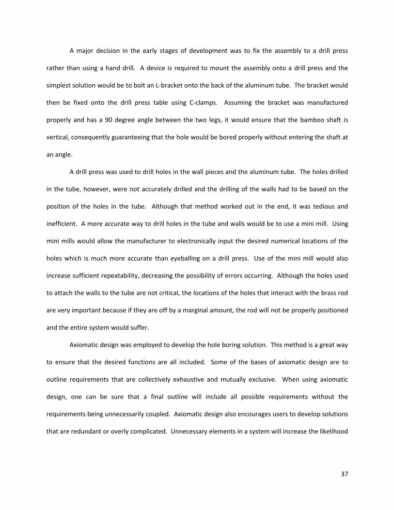
A major decision in the early stages of development was to fix the assembly to a drill press
rather than using a hand drill. A device is required to mount the assembly onto a drill press and the
simplest solution would be to bolt an L-bracket onto the back of the aluminum tube. The bracket would
then be fixed onto the drill press table using C-clamps. Assuming the bracket was manufactured
properly and has a 90 degree angle between the two legs, it would ensure that the bamboo shaft is
vertical, consequently guaranteeing that the hole would be bored properly without entering the shaft at
an angle.
A drill press was used to drill holes in the wall pieces and the aluminum tube. The holes drilled
in the tube, however, were not accurately drilled and the drilling of the walls had to be based on the
position of the holes in the tube. Although that method worked out in the end, it was tedious and
inefficient. A more accurate way to drill holes in the tube and walls would be to use a mini mill. Using
mini mills would allow the manufacturer to electronically input the desired numerical locations of the
holes which is much more accurate than eyeballing on a drill press. Use of the mini mill would also
increase sufficient repeatability, decreasing the possibility of errors occurring. Although the holes used
to attach the walls to the tube are not critical, the locations of the holes that interact with the brass rod
are very important because if they are off by a marginal amount, the rod will not be properly positioned
and the entire system would suffer.
Axiomatic design was employed to develop the hole boring solution. This method is a great way
to ensure that the desired functions are all included. Some of the bases of axiomatic design are to
outline requirements that are collectively exhaustive and mutually exclusive. When using axiomatic
design, one can be sure that a final outline will include all possible requirements without the
requirements being unnecessarily coupled. Axiomatic design also encourages users to develop solutions
that are redundant or overly complicated. Unnecessary elements in a system will increase the likelihood

38
of something failing, so by keeping the number of requirements to a minimum while maintaining that
they are exhaustive maximizes the chances that the system will be successful.
Although the prototype was never tested, one can make a legitimate assumption that it will
fulfill the main constraint supplied by the customer. Using the alignment tube, the system would only
have to be aligned with the drill press once. After that, adjusting the V-blocks would be easy especially if
the handles were improved. The assembly is designed so that the shaft can be loaded and unloaded
quickly and easily, so it is safe to assume that the design would meet the requirement of boring 30 holes
in one hour.
The drill press assembly will benefit rural villages that will adopt the Bamboo Bike Project. The
project is non-profit, so the main economic changes would be benefits to the economy of Ghana.
Implementing a safe, easy and efficient production system would create jobs for Ghanaians which would
reduce the 50% unemployment rate. Also, the introduction of cheap transportation will make life easier
for members of the society, and there would be no extreme negative effects on the environment since
the main resource is sufficiently abundant.
The previous method of boring holes was inefficient and potentially dangerous. This design will
allow for quick and efficient boring of holes in seat post shafts while keeping the user safe. Minimal
training is required to operate a drill press and the hands are kept a safe distance from the bamboo
shaft and spinning drill bit. By addressing these issues of efficiency and safety, the developed concept
greatly improves the hole boring aspect of production and increases the likelihood of a successful
manufacturing plant.

39
2.6. Conclusions
Self-centering V-blocks are an effective way to constrain bamboo for drilling.
Brass is a favorable material for the rods because it is easy to thread due to its physical properties.
It also has low frictional interaction with aluminum alloy.
Thicker brass rods would be more resilient during machining and threading.
Handle design should be improved to enhance ease of use and torque generated when constraining
bamboo.
In order to allow assembly to be mounted to drill press, a stable L-bracket should be designed.
To ensure more accurate hole location, mini mills should be used in place of drill press.
Axiomatic design is a thorough and effective way to develop a solution.

40
3. Joint Design
3.1. Design Decomposition and Constraints
For a visual of the full decomposition, see Appendix E.
3.1.1. Upper Level Decomposition
FR1-Hold Together Top Tube, Seat Tube and Seat Stays DP1-Seat Post Joint
FR2-Hold Together Seat Tube, Chain Stays and Down Tube DP2-Pedal Joint
FR3-Hold Together Seat Stays and Chain Stays DP3-Back Tire Joint
FR4- Hold Together Top Tube and Down Tube DP4-Handebar Joint Table 6: Upper level decomposition of joint design
3.1.1.1. Functional Requirements
FR0 is to secure the frame elements. This can be accomplished by securing each joint
individually. This is why the decomposition of the problem starts by differentiating which combinations
of elements need to be held together in order to secure the frame as a whole. By separating the joints it
is obvious that the solution will be mutually exclusive since there is no overlap between joints. This
method also ensures that the entire frame will be secured if each FR is satisfied. The original
decomposition had orientation and transferring of forces as FR one and two but it was difficult to
continue decomposition in that manner and ensure that all joints were accounted for.
3.1.1.2. Design Parameters
41
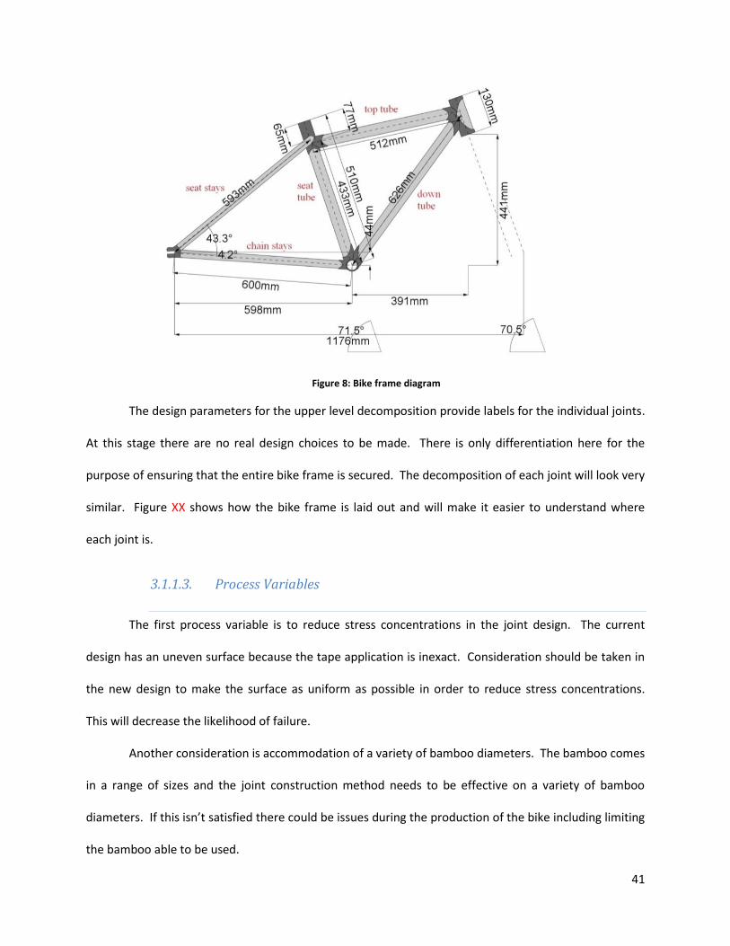
Figure 8: Bike frame diagram
The design parameters for the upper level decomposition provide labels for the individual joints.
At this stage there are no real design choices to be made. There is only differentiation here for the
purpose of ensuring that the entire bike frame is secured. The decomposition of each joint will look very
similar. Figure XX shows how the bike frame is laid out and will make it easier to understand where
each joint is.
3.1.1.3. Process Variables
The first process variable is to reduce stress concentrations in the joint design. The current
design has an uneven surface because the tape application is inexact. Consideration should be taken in
the new design to make the surface as uniform as possible in order to reduce stress concentrations.
This will decrease the likelihood of failure.
Another consideration is accommodation of a variety of bamboo diameters. The bamboo comes
in a range of sizes and the joint construction method needs to be effective on a variety of bamboo
diameters. If this isn’t satisfied there could be issues during the production of the bike including limiting
the bamboo able to be used.

42
3.1.2. Lower Level Decomposition
FR1.1-Orient Frame Elements DP1.1-Orientation Jig
FR1.3-Hold Bamboo in Correct Location DP1.3-Epoxy
FR1.4-Transfer Loads From Rider DP1.4-Force Distribution System
FR1.4.1-Transfer Axial Force Along Top Tube DP1.4.1-Resistance Force of Support Material Along Top Tube
FR1.4.2-Transfer Axial Force along Seat Tube DP1.4.2-Resistance Force of Support Material Along Seat Tube
FR1.4.3-Transfer Axial Forces along Seat Stays DP1.4.3-Resistance Force of Support Material Along Seat Tube
FR1.4.4-Transfer Moment at Top Tube About X-axis
DP1.4.4-Interface Between Epoxy and Top Tube
FR1.4.5-Transfer Moment at Seat Tube About X-axis
DP1.4.5-Interface Between Epoxy and Seat Tube
FR1.4.6-Transfer Moments at Seat Stays About X-axis
DP1.4.6-Interface Between Epoxy and Seat Stays
Table 7: Decomposition of seat post joint
Only the seat post joint is shown broken down for the sake of simplicity. All the joints follow a
similar pattern with the only difference being the elements that need to be constrained.
3.1.2.1. Functional Requirements
Each joint has three requirements that need to be satisfied in order for it to be held together
properly. The first is to orient the frame elements properly. This is necessary to ensure the bike has the
proper shape and that the bikes are consistent with each other. After the frame elements are oriented
they need to be held in place. This ensures that the elements of the bike frame won’t lose their shape.
The last element to the holding a joint together is to transfer the loads from the rider. This ensures that
the bike will continue to keep its shape during use.
The loads that need to be transferred can be broken up into two categories. The first forces are
the axial forces along each element of the joint. This ensures that the bike frame elements don’t come
apart but also that the frame elements don’t push on each other too hard which could cause unwanted
stress on the bamboo. By transferring the axial forces on the bamboo moments about the Y and Z axes
are rested. This is because the pairs of forces that would cause these moments would all be along the X-

43
axis of the bamboo. The other set of forces that need to be transferred are the moments about the X-
axis of each element. These forces need to be resisted to ensure that the bike elements aren’t able to
twist about their axis which would cause instability and possible danger to the rider.
3.1.2.2. Design Parameters
Each set of elements is held together by a joint system. The case shown in figure XX is the seat
post joint. The first element of each joint is the orientation. The orientation of the joint is determined
by a re-usable orientation jig that the frame is mounted on during the assembly process. This is already
in use with the current process. The joint is held together using epoxy. This is also part of the current
process but doesn’t need to be changed as this part of the joint is effective. The final piece of the joint is
the force distribution system. This is the portion of the joint design that has multiple design options.
The forces are transferred using two different elements of the joint. The axial forces along each
element of the joint are transferred using the reaction forces of the support material. Currently this is
the carbon fiber wrapping but alternative designs are under consideration including a metal shell. The
advantaged and disadvantages of each are discussed in depth later in the report. The moments about
eh X-axis of each frame element are rested by the frictional force at the interface of the epoxy and the
frame element. This has already been proven effective and with the further support of outer material of
the joint is more than sufficient at preventing rotation.
44
3.2. Physical Integration
3.2.1. Design Parameters and Functional Requirements
3.2.1.1. Critical Surfaces of Seat Joint
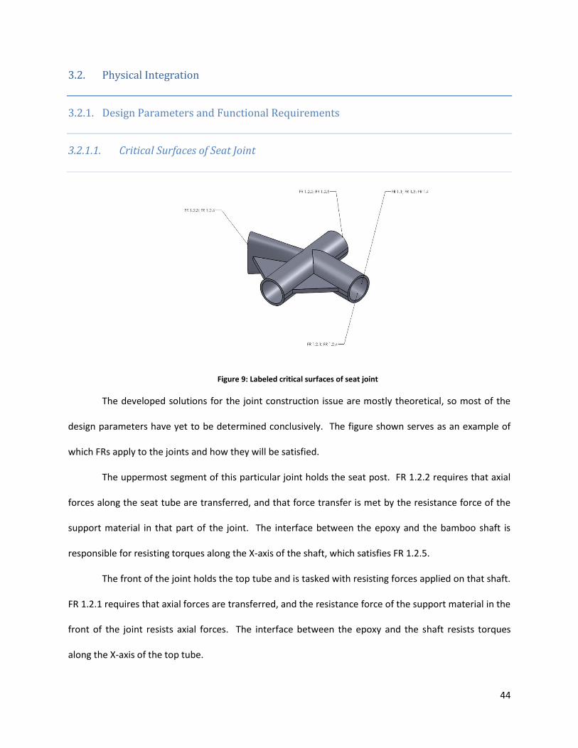
Figure 9: Labeled critical surfaces of seat joint
The developed solutions for the joint construction issue are mostly theoretical, so most of the
design parameters have yet to be determined conclusively. The figure shown serves as an example of
which FRs apply to the joints and how they will be satisfied.
The uppermost segment of this particular joint holds the seat post. FR 1.2.2 requires that axial
forces along the seat tube are transferred, and that force transfer is met by the resistance force of the
support material in that part of the joint. The interface between the epoxy and the bamboo shaft is
responsible for resisting torques along the X-axis of the shaft, which satisfies FR 1.2.5.
The front of the joint holds the top tube and is tasked with resisting forces applied on that shaft.
FR 1.2.1 requires that axial forces are transferred, and the resistance force of the support material in the
front of the joint resists axial forces. The interface between the epoxy and the shaft resists torques
along the X-axis of the top tube.

45
The rear of this joint holds the seat stays which lead to the rear joints. FR 1.2.3, which asks that
axial forces along seat stays are transferred, is fulfilled by the resistance force in the back of the joint.
The interface between the surfaces of the seat stays and the epoxy, similar to the other parts of the
joint, resists moments created by twisting of the shafts along their respective x-axes.
3.2.1.2. Compatibility Matrix
Similar to the technique used for the drill press assembly, a compatibility matrix was analyzed
for the joint design to make sure that coupling was kept to a manageable level. Figure 10 shows the
compatibility matrix.
Figure 10: Compatibility matrix for joint design
The table was only expanded to show analysis of one joint, the seat post joint. The matrix
shows that there is no coupling in the system. Each functional requirement of the joint corresponds to
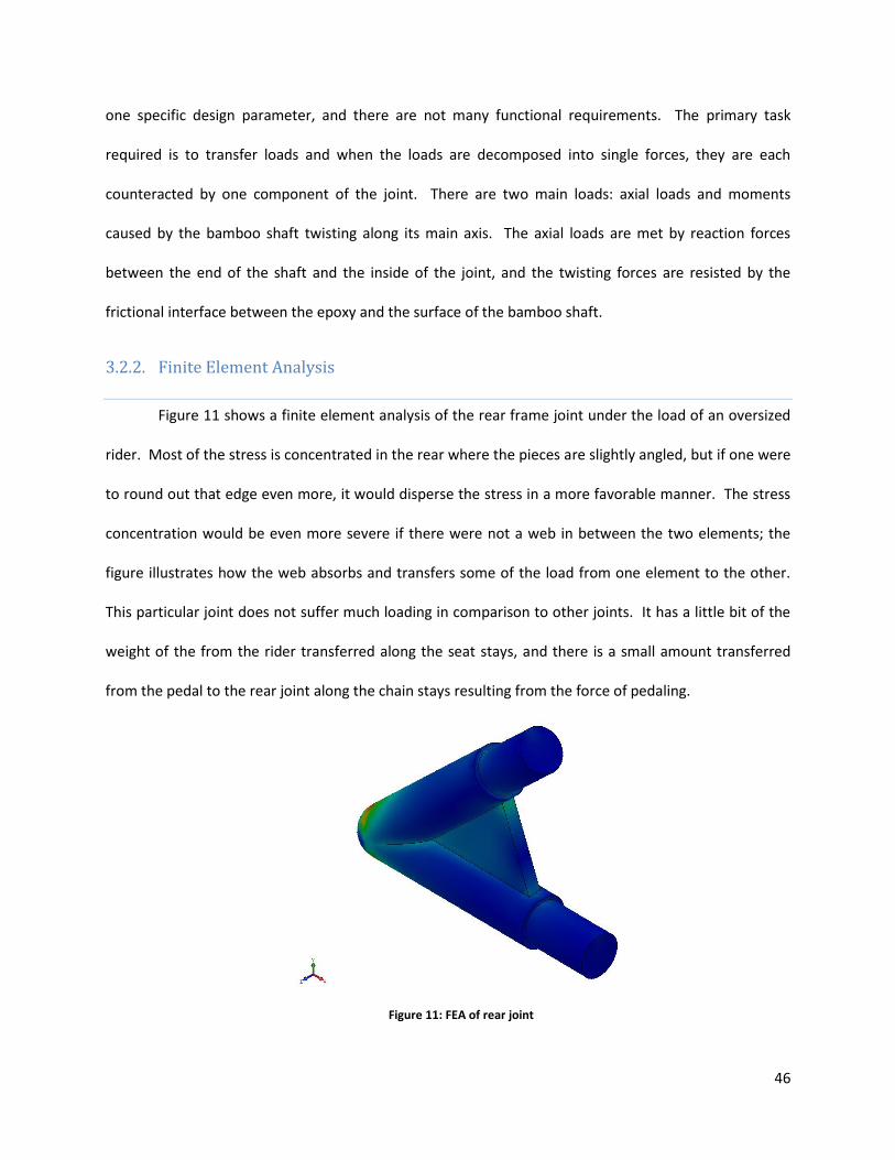
46
one specific design parameter, and there are not many functional requirements. The primary task
required is to transfer loads and when the loads are decomposed into single forces, they are each
counteracted by one component of the joint. There are two main loads: axial loads and moments
caused by the bamboo shaft twisting along its main axis. The axial loads are met by reaction forces
between the end of the shaft and the inside of the joint, and the twisting forces are resisted by the
frictional interface between the epoxy and the surface of the bamboo shaft.
3.2.2. Finite Element Analysis
Figure 11 shows a finite element analysis of the rear frame joint under the load of an oversized
rider. Most of the stress is concentrated in the rear where the pieces are slightly angled, but if one were
to round out that edge even more, it would disperse the stress in a more favorable manner. The stress
concentration would be even more severe if there were not a web in between the two elements; the
figure illustrates how the web absorbs and transfers some of the load from one element to the other.
This particular joint does not suffer much loading in comparison to other joints. It has a little bit of the
weight of the from the rider transferred along the seat stays, and there is a small amount transferred
from the pedal to the rear joint along the chain stays resulting from the force of pedaling.
Figure 11: FEA of rear joint

47
See figure 12 below for finite element analysis of the seat joint. Stress is transferred fairly well
in this particular joint, and the most prominent concentrations are in the web between the seat post
and the seat stays. However if there were no web there, those stresses would all be concentrated in a
much smaller area, the junction between the seat post and seat stays, and could reach potentially
dangerous amounts. The other web can also be seen successfully spreading the stress without letting it
concentrate unnecessarily in any areas. There is a fair amount of compressive force on the top element
but that piece will be made of metal most likely and will probably have sufficient strength. The seat post
joint is assumed to withstand the highest amount of loading due to its proximity to the primary source
of force. The rider sits directly above the seat joint with most of his or her weight concentrated on the
seat and a much less significant amount focused on the handle bars.
Figure 12: FEA of seat joint
Below, figure 13 shows finite element analysis of the pedal joint. The most stress in this joint
will be coming from the seat post up above, which will be acted on directly by the weight of the rider.
There will be smaller forces from either side as well; one from the down tube as a result of the rider
applying force on the handle bars, and a small amount will be transferred from the rear joint. The webs
on either side of the seat post are clearly under the most stress, but that is desirable because their

48
function is to transfer loads. The seat post itself is also under considerable compressive force but
bamboo has the mechanical properties to withstand that, as demonstrated in bamboo bikes that have
already been built and proven. The pedal joint does not experience loading as heavy as that of the seat
post joint, but there is more loading on this joint than the handle joint and the rear joints. There is a
considerable amount of force applied through axial transfer via the seat post, and there is dynamic
loading from the force applied during pedaling.
Figure 13: FEA of pedal joint
Figure 14 below illustrates the stress dispersion in the handle joint. Of all the joints, the handle
joint seems to suffer the least loading. The only load directly applied is the minor load from the hands
of the rider, and the load from the seat post is transferred mostly to the other joints rather than the
handle joint. In the current model, stress is concentrated at the central junction where the pieces come
together but that issue can be easily resolved by rounding out that area to smooth the stress
concentrations. The lower web observes a noticeable amount of stress as well, but again, that is the
purpose of the webs and they should be able to withstand these amounts of stress.
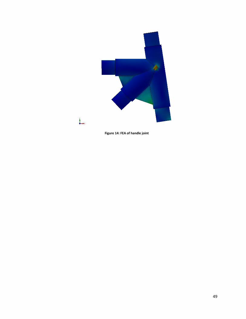
49
Figure 14: FEA of handle joint

50
3.3. Discussion
As stated in the state of the art, the original method of attaching bamboo elements to one
another is tedious and labor intensive. The pieces are shaped and hot glued to a foam piece to position
them, and then an epoxy is applied. The joint is then wrapped in carbon fiber ribbon and then electrical
tape to hold it all together. It can take up to 8 hours to teach someone this method of joint assembly,
and even for an experienced individual it takes about 40 minutes for each joint.
With the shell design, there are two options: the shell can be a reusable mold for shaping the
joints, or shells can be mass produced as permanent fixtures on the bicycle frame. Each option has pros
and cons but the main factor is maintaining a low price, since that’s a driving force of the bamboo bike
project. Each design also employs the web design to transfer forces between elements. The finite
element analysis section describes it in more detail.
If the shells were made as molds and reused, it would be much cheaper because fewer sets
would have to be created. Also, the material requirements would be significantly less demanding since
the shells wouldn’t be a permanent part of the frame; weight and strength would not matter as much.
Using carbon fiber instead of a permanent shell would also benefit the bike frame by making it weigh
less. The overall design of the shell molds would be much simpler because it would not need to be
fastened permanently, and the shape could be cut out of a block of stock rather than machining the
exact shape of the entire joint. This leads to lower manufacturing demands and lower costs. However,
the concept of temporary shells requires an additional element, such as carbon fiber, to provide
structural support since epoxy would not be adequate by itself. There would be an additional,
potentially complicated step in the process if the carbon fiber cloth were to be used.
Permanent shells would supply structural integrity, and the process of assembly would be
simpler. It would consist of positioning the bamboo shafts inside the shell and then injecting epoxy.
After letting the epoxy harden, the frame would be ready for the next step of assembly. Carbon fiber
51
sleeves would not be required so a complicated step in the process would be consequently removed.
However, if the shells are made for each bike frame and permanently attached, cost becomes an issue.
It would be much more expensive to produce sets of shells for each frame with each frame requiring 5
joints. The material used for the shells would also need to fulfill specific requirements such as providing
sufficient strength while remaining lightweight. The pieces would most likely be produced here in the
United States and shipped to Ghana, which would further complicate the process.
Though no physical solution was developed, the concepts created should be further pursued
because the end result will most likely prove to be a better design than the current method. The current
method of assembling joints has been labeled as tedious, time consuming, and inefficient overall. Either
way of using the shells would provide a simpler and easier method of assembly resulting in an overall
reduction in the time required to build a bike. Both designs will also have structural strength equal to or
greater than that of the current method.
The constraints for the joint design issue are that it must accommodate for multiple shaft
diameters, and it must eliminate stress concentrations on the surface of the joint. The shell concept is
designed to be oversized, which will accept multiple shaft sizes because the injected epoxy will form
around the contours of the bamboo and fill in the empty space. Since the joint created will be a solid
formed by a hardening epoxy, the joint will have a uniform surface with minimal stress concentrations.

52
3.4. Conclusions
The current joint design is tedious and labor intensive.
Webs between joint elements are a proficient method of transferring loads through the joint.
The two options for joint design, permanent or temporary shells, each have their pros and cons.
Permanent shells add structural integrity and simplify the assembly process but they
would be expensive and require added steps in manufacturing.
Temporary shells reduce cost and production but they complicate the assembly process
and that solution would require an additional structural element such as carbon fiber
cloth.
Further time should be spent researching and developing better joint designs.

53
4. References
[1] Amiss, John Milton, Franklin Day Jones, Henry H. Ryffel, and Christopher J. McCauley. Guide to
the Use of Tables and Formulas in Machinery's Handbook, 28th Edition. New York: Industrial, 2008. Print.
[2] Huston, Ronald L., Harold Josephs, and Alexander Blake. Practical Stress Analysis in Engineering
Design. Boca Raton: CRC, 2009. Print.
[3] Bamboo Bike Project. Web. <http://www.bamboobike.org/>.
[4] “Human Performance Capabilities.” Man-Systems Integration Standards (MSIS). Web. 28 Apr.
2011. <http://msis.jsc.nasa.gov/sections/section04.htm>.
[5] Li, Xiaobo. Physical, Chemical, and Mechanical Properties of Bamboo and its Utilization Potential
for Fiberboard Manufacturing. MA Thesis. Chinese Academy of Forestry, China, 2002.

54
5. Appendices
A. Documentation of Current Methods
The current method uses a hand drill, which is both inaccurate and dangerous.
Jigs that are used to hold the frame of the bamboo in place as it is tack welded.

55
Currently, this is what the joints look like after it has gone through the epoxy and carbon fiber
wrapping process.

56
B. Full Decomposition of Hole Boring System
Figure 15: Full decomposition of hole boring system

57
C. Iterations of Hole Boring System
Appendix C will discuss the iterations created during the process of developing a hole boring
system. Basic designs were conceived to fulfill the functional requirements and they were altered and
built upon to meet the requirements in better ways. A picture of the final design is in section 2.2 of the
report.
Figure 16: First iteration
The first iteration of many, this is a very basic design. It served more as a visualization tool than
a hopeful final product, and it helped the group by illustrating some of the early issues that would be
considered when designing a shaft constraint system. The V-block shape was chosen to maximize the
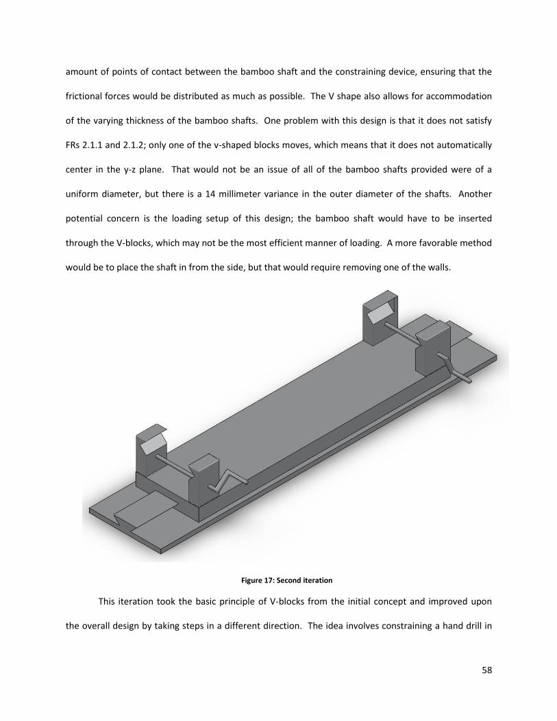
58
amount of points of contact between the bamboo shaft and the constraining device, ensuring that the
frictional forces would be distributed as much as possible. The V shape also allows for accommodation
of the varying thickness of the bamboo shafts. One problem with this design is that it does not satisfy
FRs 2.1.1 and 2.1.2; only one of the v-shaped blocks moves, which means that it does not automatically
center in the y-z plane. That would not be an issue of all of the bamboo shafts provided were of a
uniform diameter, but there is a 14 millimeter variance in the outer diameter of the shafts. Another
potential concern is the loading setup of this design; the bamboo shaft would have to be inserted
through the V-blocks, which may not be the most efficient manner of loading. A more favorable method
would be to place the shaft in from the side, but that would require removing one of the walls.
Figure 17: Second iteration
This iteration took the basic principle of V-blocks from the initial concept and improved upon
the overall design by taking steps in a different direction. The idea involves constraining a hand drill in
59
line with the axis of the bamboo shaft, and sliding the shaft constraining system toward the drill to bore
a hole while the shaft is secured in place.
FRs 1 and 5 (load and unload shaft) were considered and the loading method was altered. Rather
than threading the shaft through V-block systems, this design allows the user to drop the shaft in from
above for more rapid production. The handles are then turned to clamp the V-blocks around the
bamboo. The V-blocks are internally threaded, one is left hand and the other is right hand threaded to
allow for movement in the opposite direction. Consequently the V-blocks are self-centering and ensure
that the center of the bamboo shaft will always be in the same location despite the varying outer
diameters, thus satisfying FRs 2.1.1 and 2.1.2. The base of the design includes a ridge to constrain the
block to a linear path while sliding the system.
Although this iteration covered some of the holes left by the original concept, there were still
many facets upon which to improve. The V-blocks are not secured to the main block, and the group was
unable to determine how to constrain a hand drill.

60
Figure 18: Third iteration
It was decided that constraining a hand drill would prove to be harder than attaching our system
to a drill press, so this iteration was intended to be fastened to a drill press. The large block on the base
of the main block serves the purpose of aligning the system with the drill (FR 3.2) by being clamped to
the drill press table. The ring to the left of the frame is concentric with the bamboo shaft, and is meant
to guide the drill bit through to ensure that a hole is bored in the correct location.
Another issue addressed with this iteration is the lack of a force guiding the V-blocks as they go
through the aligning motion. The inverted triangular path concept was taken from the previous design

61
and utilized to constrain the individual V-blocks. However one problem with this iteration is that there
is nothing holding the V-blocks in place, as they can still slide along that path without much resistance.
Figure 19: Fourth iteration
In the next iteration, the alignment ring was eliminated because it was deemed unnecessary.
With this system, the goal was to fasten a tube into the V-blocks and use it to align the system with the
drill. Since the attachment needs to be attached only once, a ring that ensured alignment with every
boring motion was ultimately decided to be superfluous.
The other major change to the design was the inclusion of the curved walls outside the V-blocks.
These walls served the purpose of preventing the V-blocks from sliding undesirably in the Y-direction,

62
thus satisfying FR 2.2.5. Since the walls align the V-blocks, the tracks from the previous iteration were
removed in order to eliminate redundancy in the design.
Figure 20: Fifth iteration
The outer walls in iteration four were poorly planned as far as attachment to the main base
goes, so in that sense they lacked some feasibility. To remedy that problem, they were replaced with
rectangular walls meant to be bolted to the main base.
The bolt running through the V-blocks was also modified for the sixth iteration. A shoulder
feature was added to it; the varying diameters ensure that the V-block assemblies can’t slide along the
Y-axis. And finally, the fillets were replaced with chamfers on the edges.

63
Figure 21: Sixth iteration
For further optimization, the outer walls were shortened and a pocket was added to the main
base. These modifications reduced the weight of the overall assembly by eliminating unnecessary
material.
The bolt was also modified; brass was chosen for the material due to its more favorable
frictional properties. It was also extended outwards to allow for attachment of a handle.

64
D. CNC Machining Documentation
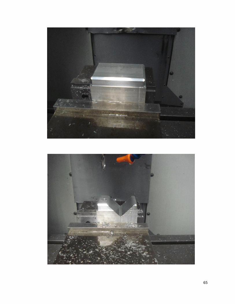
65

66
E. Full Decomposition of Joint Design
Figure 22: Full decomposition of joint design