Production Research Development
12
Measuring Instruments for the Battery Industry Introducing HIOKI’s line of measuring instruments for the battery industry Production Processes Research Development
Transcript of Production Research Development

Measuring Instruments for the Battery Industry
Introducing HIOKI’s line of measuring instruments for the battery industry
DevelopmentResearch
ProductionProcessesProduction ProcessesResearch Development

2
Supporting the batteries of todayLeading the way to the batteries of tomorrowHioki contributes to the manufacture and development of batteries with comprehensive and robust measurement solutions.
Commercialization of lithium-ion batteries is proceeding across the boardas manufacturers bring to market products ranging from compact to large-scale models.
Lithium-ion batteries (LIBs), a type of rechargeable battery notable for their extremely high level of performance, have been used primarily in off-the-shelf products such as notebook computers and mobile phones. Over the past few years, manufacturers have been working with automakers and other companies to optimize the LIBs used in electric and plug-in hybrid vehicles with large variants that offer an even higher level of performance and technology in the form of enhanced safety, higher output, and longer service life. Efforts are also underway to bring LIBs to fixed installations and industrial applications, including use in storage systems in residential and commercial settings (for example in buildings, shops, and manufacturing plants), in industrial machinery such as forklifts, and as emergency power supplies for facilities such as mobile phone base stations.
Types of batteries
Manganese batteriesAlkaline batteriesEtc.
NiCad batteriesNiMH batteries
Chemical batteries
Fuel cells
Primary batteries
Rechargeable batteries
All-solid
Liquid
Lead-acid batteries
Lithium-ion batteries
Alkaline storage batteries

3
Lithium-ion and next-generation batteries
Electrolyte
Charging
Negativeelectrode
Positiveelectrode
Discharging
Separator
Li+Li+Li+Li+Li+Li+
Li+
Li+
Li+
Li+Li+Li+
Li+Li+Li+Li+Li+Li+
Li+Li+Li+
e- LoadLithium-ion batteries (liquid)
Lithium-ion batteries, a type of rechargeable battery in which charging and discharging is accomplished by the movement of lithium ions between positive and negative electrodes, are expected to see broad use in applications ranging from off-the-shelf commercial goods to vehicles due to their low weight and high capacity. As part of the global effort to wean society off carbon-based sources of energy, research is expanding to boost capacity and extend service life for use in electric vehicles.
All-solid lithium-ion batteries
All-solid batteries would offer a higher level of safety since they do not use flammable electrolyte. Research is underway to develop such batteries for use in vehicles since they can be charged in several minutes.
Discharging
Li+ Li+
Li+ Li+
Solid electrolyteNegative electrode active material
Positive electrode active material
e- Load
Charging
Fuel cells
Fuel cells are like generators that use a substance such as hydrogen as fuel. Fuel cell-powered vehicles offer a high level of convenience compared to electric vehicles thanks to their long range and fast fill-up times. Fuel cells are a well-established technology that has already been used in applications such as forklifts and residential cogeneration systems.
Oxygen
Water
Hydrogen
H+
H+
H2
H2O
O2
O
OH+
H+
Hydrogenelectrode(negative)
Airelectrode(positive)
Electrolyte
Load
H+H+H+
H+H+H+
e-e-
e-
e-e-
e-
500
Lead-acid batteries
Mass energy density (Wh/kg)
Volumetric energy density (Wh/L)
Lithium-ion batteries
Lithium-air batteries
NiCad batteries
All-solid batteries
NiMH batteries
Fuel cells
00
500
100015002000
1000 1500
Next-generation battery technologies
(*Research by Hioki)
4
Electrode Resistance Measurement System RM2610
Electrode sheetsslurry Coater press slittingSheet cutting and
stacking Tab welding
LiB research and development as quality control of electrode sheets continues to evolve
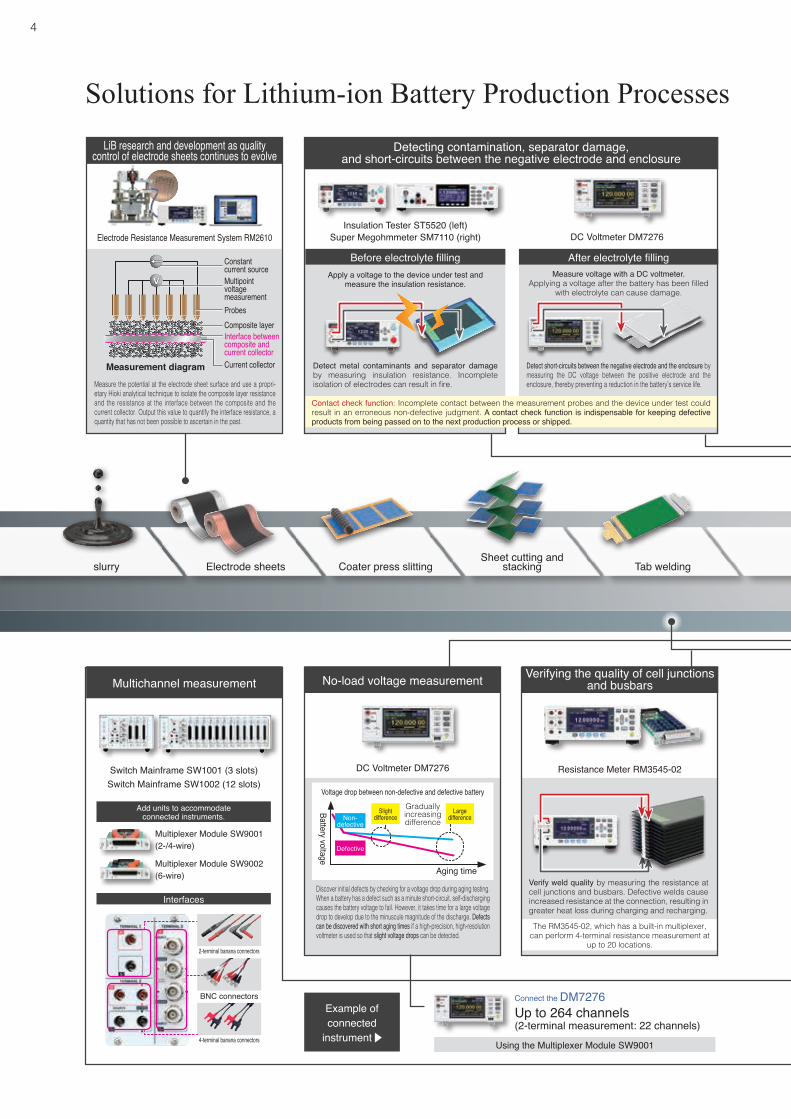
Solutions for Lithium-ion Battery Production Processes
Measure the potential at the electrode sheet surface and use a propri-etary Hioki analytical technique to isolate the composite layer resistance and the resistance at the interface between the composite and the current collector. Output this value to quantify the interface resistance, a quantity that has not been possible to ascertain in the past.
DC Voltmeter DM7276 Resistance Meter RM3545-02
No-load voltage measurement Verifying the quality of cell junctions and busbars
Discover initial defects by checking for a voltage drop during aging testing. When a battery has a defect such as a minute short-circuit, self-discharging causes the battery voltage to fall. However, it takes time for a large voltage drop to develop due to the minuscule magnitude of the discharge. Defects can be discovered with short aging times if a high-precision, high-resolution voltmeter is used so that slight voltage drops can be detected.
Gradually increasing difference
Slight difference
Large difference
Voltage drop between non-defective and defective battery
The RM3545-02, which has a built-in multiplexer, can perform 4-terminal resistance measurement at
up to 20 locations.
Verify weld quality by measuring the resistance at cell junctions and busbars. Defective welds cause increased resistance at the connection, resulting in greater heat loss during charging and recharging.
Constantcurrent sourceMultipointvoltagemeasurementProbes
Interface betweencomposite andcurrent collector
Composite layer
Current collectorMeasurement diagram
Insulation Tester ST5520 (left)Super Megohmmeter SM7110 (right)
Before electrolyte fillingApply a voltage to the device under test and
measure the insulation resistance.
DC Voltmeter DM7276
After electrolyte fillingMeasure voltage with a DC voltmeter.
Applying a voltage after the battery has been filled with electrolyte can cause damage.
Detect metal contaminants and separator damage by measuring insulation resistance. Incomplete isolation of electrodes can result in fire.
Detect short-circuits between the negative electrode and the enclosure by measuring the DC voltage between the positive electrode and the enclosure, thereby preventing a reduction in the battery’s service life.
Contact check function: Incomplete contact between the measurement probes and the device under test could result in an erroneous non-defective judgment. A contact check function is indispensable for keeping defective products from being passed on to the next production process or shipped.
Detecting contamination, separator damage,and short-circuits between the negative electrode and enclosure
Multichannel measurement
Switch Mainframe SW1001 (3 slots)Switch Mainframe SW1002 (12 slots)
2-terminal banana connectors
4-terminal banana connectors
BNC connectors
Multiplexer Module SW9001 (2-/4-wire)
Multiplexer Module SW9002 (6-wire)
Up to 264 channels (2-terminal measurement: 22 channels)
Connect the DM7276
Using the Multiplexer Module SW9001
Interfaces
Example of connected
instrument
Add units to accommodateconnected instruments.
Battery voltage
Aging time
Non-defective
Defective

5
Power Analyzer PW6001 Battery Cell Voltage Generator SS7081
Evaluate high-voltage, high-current setups with the instrument’s 1500 V/2000 A range.
Built-in high-accuracy output circuitry and voltage monitoring circuitry support high-precision BMS ICs.
Simulate open wires and shorts in a battery of up to 1000 V with channels connected in series.
Wireless Logging Station LR8410
Simultaneously testing temperature and voltage
Evaluate batteries during aging and actual operation.
Continuously monitor up to 105 channels.Simultaneously measure temperature, heat flows,
and cell terminal voltage.Accurately assess the relationship between battery characteristics, temperature, and heating by simultaneously measuring temperature, heat flows, and voltage at multiple points. Simultaneous, multipoint measurement capability is a must since high module voltages mean more cells to test.
ModulesPack testingSeal vacuum drying
Electrolyte filling and impregnation Discharge aging Cell testing
Test charge and discharge Evaluate and test BMS
BatteryCharge/dis-charge power supply
CurrentSensor
Accurately identify capacity (Ah, Wh), charge/discharge curves, and charge/discharge energy efficiency and loss by simultaneouslymeasuring voltage and current during charge cycles. Integrate into a system linked to a charge/discharge power supply.
High-accuracy signal generation and measurement capabilities are useful when evaluating BMS performance. In addition, the ability to verify performance under abnormal conditions is useful when evaluating safety.
BMS boardCH1 CH2 CH12 COM
12 channel connection example
• • • • • • • • • • • • • •
Up to 72 channels (4-terminal pair measurement: 6 channels)
Up to 132 channels (4-terminal measurement: 11 channels)
Connect the BT4560/IM3590 Connect the BT3562
Using the Multiplexer Module SW9002 Using the Multiplexer Module SW9001
Battery Impedance Meter BT4560 / Chemical Impedance Analyzer IM3590
Discovering and analyzing the causes of cell defects
Identify the causes of battery cell defects by measuring AC impedance at multiple frequencies. For example, you can identify batteries that have issues with electrode reactions at the electrode interface by checking impedance at low frequencies. You can also extend this approach to cover multiple channels by combining the instrument with a switching system.
R1
R1R2
1 kHz
Test electrolyte resistance and reaction resistance.
1 Hz
R1+R2
-X
R0
Battery HiTester BT3562
Measuring internal resistance and no-load voltage
Measure internal resistance and the battery’s no-load voltage at the same time. Since measurement can be carried out quickly, this approach is well suited to shipping inspections and acceptance inspections of cells and battery packs.
Measuring internal resistance with a DC resistance meter: NoMeasuring internal resistance with an AC resistance meter: Yes
With EMF…
Battery HiTester (=AC resistance meter)AC measurement current
Batteries exhibit electromotive force (EMF).
Voltmeter

6
Evaluating charging and discharging in finished vehicles: PW6001
Measure power in up to six circuits with a single instrument.
For measuring volume resistivity, surface resistivity, and conductivity
4-point probes (5.0 mm pitch) 4-point probes (1.5 mm pitch)
Measuring the volume resistivity of composites: 4-point probes Special edition
specifications
RM3545
Accurately measure charge capacity and discharge magnitude by accurately capturing voltage and current values at 5 MHz sampling speeds as they change from moment to moment in the battery under conditions of actual operation while a finished vehicle is driven (in WLTP mode, etc.).
Supports multiple charge/discharge tests including for auxiliary batteries
Clamp-type AC/DC current probes• High accuracy: ±0.3% rdg.• Operating temperature range: -40°C to 85°C• 20 A to 1000 A
Drive battery
Power Analyzer PW6001
Inverter Motor
Measurement frequency: 1 mHz to 200 kHzRange: 100 mΩ to 10 ΩMax. battery voltage: 5 V
Measurement frequency: 4 Hz to 10 MHzRange: 100 Ω to 10 kΩMax. battery voltage: 10 V
Measuring the internal impedance of all-solid batteries requires a broader frequency band than is needed when testing LIBs, which use conventional electrolyte.
Measurement using the IM3536-01 and 9268-10Measure up to 10 MHzMax. input voltage: 10 V
All-solid batteries(Single-cell/module)
IM3590 IM3536-01 + 9268-10
-X
R
1 MHz
1 Hz
Measuring all-solid batteries: IM3536-01 / IM3590 Special edition specifications
IM3536-01
9268-10
Verify the state of electrolyte and electrodes by measuring the battery’s internal impedance and displaying a Cole-Cole plot.
(*A desktop computer is required in order to display Cole-Cole plots based on measurements made with the IM3536-01.)
Measuring the internal resistance of fuel cells: BT3563/BT3564
Max. input voltage±300 V DC (BT3563)±1000 V DC (BT3564)
Simulated FC load
Measurement of fuel cell’s internal resistance
BT3563/BT3564 withspecial edition specifications
Assess fuel cell characteristics in real time while under load.
Fuel cell(FC)
The BT3563/BT3564 with special edition specifications features increased noise resistance to reduce the effects of noise from load devices. The instrument can ascertain fuel cell state based on impedance measured at a frequency of 1 kHz.
Loaddevice
Special edition specifications
Detecting battery pack wire breaks: BT4560 (10 V/20 V)
BT4560 suitable for use with 10 V/20 V input
*Battery packs with protective circuits cannot be tested.
Detection of defects is difficult due to the small difference in impedance values exhibited by non-defective and defective products.
Detection of wire breaks is simple since it is possible to compare points exhibiting large differences.
Defective product
Non-defective product
Defective product
Large difference
Non-defective product
1 kHz
1 kHz (high frequency)
Sweep from 0.1 Hz (low frequency)
0.1 Hz
-X
R
Detect wire breaks in battery packs with sweep measurement starting at a low frequency.
Solutions for Research & Development
7
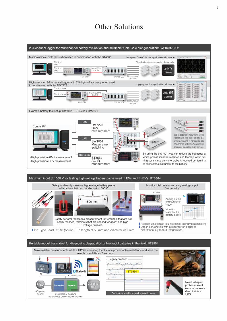
Example battery test setup: SW1001 + BT3562 + DM7276
Multipoint Cole-Cole plots when used in combination with the BT4560
High-precision 264-channel logger with 7.5 digits of accuracy when used in combination with the DM7276
Battery
Battery
Battery
Battery
264-channel logger for multichannel battery evaluation and multipoint Cole-Cole plot generation: SW1001/1002
Control PC
By using the SW1001, you can reduce the frequency at which probes must be replaced and thereby lower run-ning costs since only one probe is required per terminal to connect the instrument to the battery.
LANDM7276OCVmeasurement
SW1001Measurement switching
LAN
RS-232C
Use of separate instruments would necessitate two connections per terminal, resulting in increased probe maintenance and more measurement stoppages caused by faulty contact.
Other Solutions
Connection cable
Connection cable
Multipoint Cole-Cole plot application windows
Logging function application window
Up to 72 channels
Up to 264 channels
Control wire
Control wire
*Application supports up to 18 channels.
BT4560
DM7276 SW1001/02
SW1001/02
Control wireControl wire
Measurement cables
Measurement cables
Maximum input of 1000 V for testing high-voltage battery packs used in EVs and PHEVs: BT3564
Portable model that’s ideal for diagnosing degradation of lead-acid batteries in the field: BT3554
Analog output to recorder or logger
R
Time
Vibration tester for EV battery packs
Record fluctuations in total resistance during vibration testing. Use in conjunction with a recorder or logger to simultaneously record temperature. Pin Type Lead L2110 (option): Tip length of 50 mm and diameter of 7 mm
Safely and easily measure high-voltage battery packs with probes that can handle up to 1000 V.
Monitor total resistance using analog output functionality.
Safely perform resistance measurement for terminals that are not easily reached, terminals that are spaced far apart, and high-
voltage busbars.
New L-shaped probes make it easy to measure deep inside a UPS.
Make reliable measurements while a UPS is operating thanks to improved noise resistance and save the results in as little as 2 seconds.
Even reliably measurecontinuously online inverter systems
AC power supply Comparison with superimposed noise
Legacy product
BT3554
Converter Inverter
UPS battery
Distributionpanel
BT3564
BT3554-01/-11
1500 mm
•High-precision AC-IR measurement•High-precision OCV measurement
BT3562AC-IR measurement

8
Evaluation of battery performance
Evaluation of battery performance
· Maximum input range of 300 V (BT3563) or 60 V (BT3562)· Production-line testing of high-voltage battery packs and
battery modules· Testing of large (low-resistance) cells· Built-in contact check function
Battery HiTester BT3562/BT3563BT3563, BT3563-01 BT3562, BT3562-01
Maximum input voltage
Rated input voltage: ±300 V DCMaximum rated voltage to ground: 300 V DC
Rated input voltage: ±60 V DCMaximum rated voltage to ground: 70 V DC
Resistance measurement ranges
7 ranges: 3 mΩ (3.1000 mΩ, resolution of 0.1 μΩ) to 3000 Ω (3000.0 Ω, resolution of 0.1 Ω)
Voltage measurement ranges
3 ranges: 6 V DC (±6.00000 V, resolution of 10 μV) to 300 V DC (±300.000 V, resolution of 1 mV)
2 ranges: 6 V DC (±6.00000 V, resolution of 10 μV) to 60 V DC (±60.0000 V, resolution of 100 μV)
Sampling speed EX.FAST: 4 ms; FAST: 12 ms; MEDIUM: 35 ms; SLOW: 150 ms
Interfaces External I/O, RS-232C, printer (via RS-232C), GP-IB (-01 models)
Functions Contact check, comparator, analog output (displayed values: 0 V to 3.1 V DC)
DC Voltmeter DM7275/DM7276DM7275 DM7276
Voltage measurement ranges
5 ranges: 100 mV (±120.000 00 mV, resolution of 10 nV) to 1000 V (±1000.000 0 V, resolution of 100 μV)
Basic accuracy 10 V range±0.0020% rdg. ±12 μV
10 V range±0.0009% rdg. ±12 μV
Input resistance 100 mV to 10 V range: 10 GΩ or greater/10 MΩ100 V, 1000 V range: 10 MΩ
Temperature measurement
-10.0°C to 60.0°C, basic accuracy of ±0.5°C(Combined accuracy with Temperature Sensor Z2001)
Interfaces
Standard interfaces: -01, -02, -03LAN (100Base-TX), external I/O, USB memory stick, USB device (USB 2.0 Full Speed)Optional interfacesGP-IB (-02 models), RS-232C (-03 models), printer (-03 models)
Functions
Measurement assistance: Smoothing function, null, temperature correction, scaling, over-display, auto-hold, contact check, self-calibrationManagement assistance: Comparator, bin judgment, absolute value judgment, level display, statistics, measurement information, communications monitor, external I/O test
· High-accuracy measurement approaching the performance of a reference instrument with one-year accuracy of 9 ppm (DM7276)
· Low-cost base model with one-year accuracy of 20 ppm (DM7275)
· Built-in capacitance-type contact check function· Universal power supply to accommodate global production
Battery HiTester BT3564Maximum input voltage
Rated input voltage: ±1000 V DCMaximum rated voltage to ground: 1000 V DC
Resistance measurement ranges
7 ranges: 3 mΩ (3.1000 mΩ, resolution of 0.1 μΩ) to 3000 Ω (3100.0 Ω, resolution of 0.1 Ω)
Voltage measurement ranges
3 ranges: 10 V DC (±9.99999 V, 10 μV) to 1000 V DC (±999.999 V, 1 mV)
DC input resistance 5 MΩ
Sampling speed 3 speeds: FAST, MEDIUM, SLOW
Response time Measurement response time: 700 ms
Interfaces External I/O, RS-232C, GP-IB, analog output
Functions Contact check, comparator, analog output (displayed values: 0 V to 3.1 V DC)
· Support for direct measurement of up to 1000 V; maximum display range of ±1100 V
· Testing of high-voltage battery packs for EVs and PHEVs· Spark discharge reduction function· Built-in contact check function
Pin Type Lead L2110High-voltage battery measurement, 1000 V DC
Tip replacement (for either L2110 or L2100)Tip Pin 9772-90For replacing the tip of the Pin Type Lead L2110/L2100
Pin Type Lead L2100High-voltage battery measurement, 1000 V DC
Options: 100 V measurement leads (for measuring high-voltage batteries)
3.9 mm
8
Product specifications *For more detailed specifications, please see the catalog for the product in question.

9
Evaluation of battery performance
Switch Mainframe SW1001/SW1002Multiplexer Module SW9001/SW9002
Switch Mainframe SW1001/SW1002Number of slots 3 (SW1001), 12 (SW1002)Supported modules
Multiplexer Module SW9001 (2-wire/4-wire)Multiplexer Module SW9002 (4-terminal-pair)
Number of connectable instruments
Max. of 2: one 2-wire instrument + one 4-wire instrument, or one 2-wire instrument + one 4-terminal-pair instrument
Maximum input voltage 60 V DC, 30 Vrms AC, 42.4 VpeakInterfaces LAN, USB, RS-232C (for host and instrument)External I/O SCAN input, SCAN_RESET input, CLOSE output (for scan control)
Multiplexer Module SW9001 Multiplexer Module SW9002Connection type 2-wire or 4-wire 4-terminal-pair (6-wire)Number of channels 22 (2-wire) or 11 (4-wire) 6 (4-terminal-pair) or 6 (2-wire)Contact type Armature relay Armature relayChannel switching time 11 ms (not including measurement time) 11 ms (not including measurement time)Maximum allowable voltage 60 V DC, 30 Vrms AC, 42.4 Vpeak 60 V DC, 30 Vrms AC, 42.4 Vpeak
Maximum allowable current 1 A DC, 1 Arms AC 1 A DC, 1 Arms AC (sense)
2 A DC, 2 Arms AC (source, return)Measurement connector D-sub 50-pin D-sub 37-pin
SW1001
SW9001
SW9002
SW1002
IM3590∙ Wide range of signal sources from 1 mHz to 200 kHz to
accommodate ion behavior and solution resistance measurement
∙ Capable of internal impedance measurement of batteries in the no-load state
∙ Cole-Cole plots, equivalent circuit analysis, etc. Capable of impedance (LCR) measurement of electrochemical components and materials
Battery Impedance Meter BT4560
Special-order models (For pricing, please request a quotation.)
Measurement frequencyStandard
0.10 Hz to 1050 HzSpecial-order
0.01 Hz to 1050 Hz
Voltage measurement
Standard
5 V (±5.10000 V)
Measurement ranges:Measurement current:
3 mΩ / 10 mΩ / 100 mΩ 1.5 A / 500 mA / 50 mA
Standard specifications
Special-order specifications (1)
Special-order
10 V (±9.99999 V)
Measurement ranges:Measurement current:
30 mΩ / 300 mΩ500 mA / 50 mA
Special-order specifications (2)
Special-order specifications (3)Special-order
20 V (-1.00000 V to 20.40000 V)
Measurement ranges:Measurement current:
30 mΩ / 300 mΩ / 3 Ω150 mA / 50 mA / 5 mA
Special-order specifications (4)
Special-order specifications (5)
FunctionsContact check function, potential gradient correction during impedance measurement, charge/discharge prevention during AC application
Interfaces RS-232C, USB
∙ Impedance measurementR accuracy: ±(0.004 |R| + 0.0017 |X|) [mΩ] + αX accuracy: ±(0.004 |X| + 0.0017 |R|) [mΩ] + α(Representative α value: 8 dgt. during SLOW operation in 3 mΩ range)
∙ Voltage measurementResolution: 10 μV; accuracy: ±0.0035% rdg. ±5 dgt.(Can measure 4 V at an accuracy of ±190 μV)
∙ Temperature measurementAccuracy: ±0.5°C (10.0°C to 40.0°C), ±1.0°C (-10.0°C to 9.9°C, 40.1°C to 60.0°C)
∙ Built-in contact check function
12 mm6.3 mmφ1.3 mm 9.1
5 mm
φ1.8 mm
2.5Clip Type Probe L2002Cable length: 1.5 m
Pin Type Probe L2003Cable length: 1.5 m
Temperature Sensor Z2005Cable length: 1 m
Options: Probes and sensors
IM3570∙ Wide range of signal sources from 4 Hz to 5 MHz
IM3590
IM3570
* The 9268-10 and IM9000 (equivalent circuit analysis software, available for separate purchase) are required in order to perform equivalent circuit analysis with the IM3570.
Impedance Analyzer IM3570Chemical Impedance Analyzer IM3590
IM3570 IM3590Measurement modes
LCR measurement, sweep measurement, equivalent circuit analysis*, continuous measurement
Measurement parameters
Z, Y, θ, Rs (ESR), Rp, Rdc (DC resistance), X, G, B, Cs, Cp, Ls, Lp, D (tan δ), Q, (IM3590 only: T, σ [conductivity], ε [permittivity])
Measurement ranges 100 mΩ to 100 MΩ (defined in terms of Z for all parameters)
Display range
Z, Y, Rs, Rp, Rdc, X, G, B, Ls, Lp, Cs, Cp: ±(0.000000 [unit] to 9.999999 G [unit])Z and Y: Displayed using absolute valuesθ: ±(0.000° to 180.000°)D: ±(0.000000 to 9.999999)Q: ±(0.00 to 99999.99)
Z, Y, Rs, Rp, Rdc, X, G, B, Ls, Lp, Cs, Cp, σ, ε: ±(0.00000 [unit] to 9.99999 G [unit])Z and Y: Displayed using absolute valuesθ: ±(0.000° to 180.000°)D: ±(0.00000 to 9.99999)Q: ±(0.00 to 99999.99)σ, ε: ±(0.00000 f [unit] to 999.999 G [unit])
Basic accuracy Z: ±0.08% rdg. θ: ±0.05° Z: ±0.05% rdg. θ: 0.03°Measurement frequency 4 Hz to 5 MHz 1 mHz to 200 kHzM
easurement signal level
NormalV or CV mode
5 mV to 5 Vrms (up to 1 MHz), 10 mV to 1 Vrms (1.0001 MHz to 5 MHz) 5 mV to 5 Vrms
NormalCC mode
10 μA to 50 mArms (up to 1 MHz), 10 μA to 10 mArms (1.0001 MHz to 5 MHz) 10 μA to 50 mArms
Low-impedance/high-accuracyV or CV mode
5 mV to 1 Vrms (up to 100 kHz) 5 mV to 2.5 Vrms
Low-impedance/high-accuracyCC mode
10 μA to 100 mArms (100 mΩ and 1 Ω ranges up to 100 kHz) 10 μA to 100 mArms
9
9268-10

10
Resistance Meter RM3545Resistance measurement ranges 10 mΩ to 1000 MΩ
Measurement current 1 A to 100 nA DC
Temperature measurement
-10.0°C to 99.9°C; basic accuracy: ±0.5°C (combined accuracy with Temperature Sensor Z2001); -99.9°C to 999.9°C (analog input)
Sampling speedFAST (2.0 ms), MED (50 Hz: 22 ms; 60 Hz: 19 ms), SLOW1 (102 ms), SLOW2 (202 ms)Speeds vary with the range; 2.0 ms is the fastest speed.
FunctionsTemperature correction, offset voltage correction (OVC), comparator (ABS/REF%), bin judgment, panel save/load, D/A output, contact check
Multiplexer Supported unit: Z3003 (up to 2) (RM3545-02 only)
InterfacesSelect 1 of the following for use with remote function, communications monitor function, data output function, and memory (50 data points): GP-IB (RM3545-01 only), RS-232C, printer (RS-232C), USB
Battery Cell Voltage Generator SS7081Number of channels 12Maximum series connections
Series connections with instrument up to a maximum serial output voltage of 1000 V
Output range(All channels are independent.)
DC voltage: 0.0000 V to 5.0250 V
Maximum output current
±1.000 00 AContinuous output within the range of -210 mA to 210 mAMaximum output time of 200 ms if output is less than -210 mA or greater than 210 mA
Measurement ranges
DC voltage -0.00100 V to 5.10000 VDC current (2 ranges) ±120.0000 μA (100 μA range), ±1.200 00 A (1 A range)
Voltage output accuracy ±0.0150% of setting ±500 μVVoltage measurement accuracy ±0.0100% rdg. ±100 μVCurrent measurement accuracy
1 A range ±0.0700% rdg. ±100 μA100 μA range ±0.0350% rdg. ±10 nA
Functions
Assistive functionality: smoothing, logging measurement, memory output, output pin switching (open, short simulation)Anomaly detection functionality: Overcurrent detection, output voltage anomaly detection, enclosure temperature anomaly detection
Power supply Universal (100 V to 240 V AC)Interface LAN
Electrode Resistance Measurement System RM2610Measurement target LIB positive electrode and negative electrode sheets
Measurement parameters
Interface resistance between composite layer and current collector [Ωcm2]Volume resistivity of composite layer [Ωcm]
Calculation method Analytical calculation based on potential distribution
Data entered in advance
Composite layer thickness [μm]Current collector volume resistance [Ωcm] and thickness [μm]
Measurement time 1 min. standard (measurement time + analysis time)
Measurement probe 46 measurement pins
System components Instrument, measurement probe, computer (provided by user)
Evaluation of connection qualityEvaluation of electrode sheet characteristics
Diagnosis of lead-acid battery degradationInsulation testing
Safety testing
ECU
and BMS evaluation and testing
10
· Maximum resolution of 0.01 μΩ, maximum measurement current of 1 A
· Measuring range of 0.00 μΩ (measurement current of 1 A)
· Multipoint measurement (20 four-terminal channels) using the Multiplexer Unit Z3003 (option)
· Built-in contact check function· Ideal for busbar measurement
Use for busbar measurement.
Multiplexer Unit Z3003 (option)
Product specifications *For more detailed specifications, please see the catalog for the product in question.
BMS boardCH1 CH2 CH3 CH4 CH5 CH6 CH7 CH8 CH9 CH10 CH11 CH12 COM
12 channel connection example
AC/DC Current Probe CT6846-051000Arms
Examples of optional current sensors
AC/DC Current Sensor CT68772000ArmsCT6877CT6846-05
Power Analyzer PW6001
FunctionsMeasurement of voltage/ current/ and power, calculation measurement, harmonic measure-
ment, waveform recording, FFT analysis, efficiency and loss calculation, user-defined calcu-lations, trend graph display, X-Y graph display, D/A output, etc.
Number of channels Max. 6 (by channel when measuring voltage and current simultaneously)Voltage ranges 6 to 1500 V, 7 rangesCurrent ranges 400 mA to 2 kA (varies with current sensor)Sampling 5 MHz/18 bitsFrequency band DC, 0.1 Hz to 2 MHz
Power accuracy ±0.02%rdg.±0.05%f.s.(DC)±0.02%rdg.±0.03%f.s.(45 to 66Hz)
Data refresh rate 10 ms/ 50 ms/ 200 msInterfaces USB memory stick, LAN, GP-IB, RS-232C, external control, 2-instrument synchronization

11
· As little as approx. 2 sec. from measurement to saving of data, 60% faster than the previous model (3554)
· Measure internal resistance and voltage to instantaneously diagnose the state of degradation as “pass,” “caution,” or “fail.”
· Built-in noise reduction technology for improved noise resistance· Built-in Bluetooth® wireless technology for real-time degradation
diagnostics (BT3554-01, BT3554-11)· Built-in contact check function· New protector delivers better ergonomic hold and durability in the field.
Battery Tester BT3554
Resistance measurement ranges
4 ranges (switchable): 3 mΩ (max. display of 3.100 mΩ and resolution of 1 μΩ) to 3 Ω (max. display of 3.100 Ω and resolution of 1 mΩ)Measurement accuracy: ±0.8% rdg. ±6 dgt. (3 mΩ range only: ±1.0% rdg. ±8 dgt.)Measurement current frequency: 1 kHz ±30 Hz; with noise frequency avoidance function enabled: 1 kHz ±80 HzMeasurement current: 160 mA (3 m/30 mΩ range), 16 mA (300 mΩ range), 1.6 mA (3 Ω range); open-terminal voltage: 5 V max.
Voltage measurement ranges
2 ranges (switchable): ±6 V (max. display of ±6.0000 V and resolution of 1 mV) to ±60 V (max. display of ±60.00 V and resolution of 10 mV)Measurement accuracy: ±0.08% rdg. ±6 dgt.
Functions Contact check, comparator, memory (6000 data points)
InterfacesBT3554-01, BT3554-11 only: Bluetooth® 4.0 LE; supported devices: smartphone and tablets running iOS 10 or greater or Android™ 4.3 or greaterGENNECT Cross (free app): Measured value list display, report creation, trend display (PC app only)
Super Megohmmeter SM7110/SM7120DC current measurement (accuracy)
20 pA range (resolution of 0.1 fA and accuracy of ±[2.0% of rdg. +30 dgt.] to 2 mA range (resolution of 10 nA and accuracy of ±[0.5% of rdg. +30 dgt.])
Resistance display range 50 Ω to 2×10¹⁹ Ω
Voltage measurement ranges (accuracy)
SM7110 and SM71200.1 to 100.0 V (resolution of 100 mV and accuracy of ±0.1% of setting ±0.05% f.s.)100.1 to 1000 V (resolution of 1 V and accuracy of ±0.1% of setting ±0.05% f.s.)SM7120 only1000 to 2000 V (resolution of 1 V and accuracy of ±0.2% of setting ±0.10% f.s.)
Current limiter 0.1 to 250.0 V: 5/10/50 mA; 251 to 1000 V: 5/10 mA; 1001 V or greater: 1.8 mA
Functions Comparator, liquid volume resistivity measurement, surface resistivity measurement, volume resistivity measurement, voltage monitor, contact check
Interfaces RS-232C, USB, GP-IB
· Noise resistance that is 300 times greater than that of the previous model
· High-speed measurement as fast as 6.4 ms· Built-in contact check function to verify contact· Max. 2×10¹⁹ Ω display and 0.1 fA resolution
· Wireless logger capable of collecting data from multiple channels using Bluetooth® technology to enable measurement in locations where it would be difficult to run wires (line of sight, 30 m)
· Add up to 7 input units (for 105 channels when using 15-channel type units) for simple, wireless expansion.
· Collect data with high-speed sampling of all channels at up to 100 ms.
· Used in conjunction with heat flow sensors, the Heat Flow Logger LR8416/LR8432 provides not only temperature, but also the direction and magnitude of heat flows.
LR8410 and LR8510 (right) (separately available option)
Wireless Logging Station LR8410Number of measurement channels
Connect up to 7 input units wireless (with Bluetooth® wireless technology) to the LR8510 or LR8511 for measurement and data collection across up to 105 channels.
Recording interval 16 settings: 100 ms, 200 ms to 1 hr. (All input channels are scanned within the recording interval.)
Memory capacity Internal memory: 8 Mwords; SD card/USB memory stickInterfaces LAN: 100Base-TX; USB: USB 2.0 series mini-B × 1
Functions Real-time saving to SD card or USB memory stick, value/waveform calculations, 4-channel alert output (non-isolated), etc.
LR8510 measurement functionality
Number of channels: 15 isolated channels of analog scanning input (2-pole terminal block with M3 screws)Voltage measurement range: ±10 mV to ±100 V, 1 to 5 V, resolution of 500 nVThermocouple measurement range: -200°C to 2000°C, thermocouple (K, J, T, other), resolution of 0.01°C
LR8511 measurement functionality
Number of channels: 15 isolated channels of analog scanning input (4-pole push-button terminal block)Voltage measurement range: ±10 mV to ±100 V, 1 to 5 V, resolution of 500 nVThermocouple measurement range: -200°C to 2000°C, thermocouple (K, J, T, other), resolution of 0.01°CResistance bulb measurement range: -200°C to 800°C, resolution of 0.01°C (non-isolated channels)Resistance measurement range: 0 to 200 Ω, resolution of 0.5 mΩ (non-isolated channels)Humidity measurement range: 5.0 to 95.0% RH, resolution of 0.1% RH (non-isolated channels)Maximum channel-to-channel voltage: 300 V DCMaximum input voltage: ±100 V DCMaximum voltage to ground: 300 V AC/DC
· Get decisions in as quickly as 50 ms· Freely configurable test voltage (1 V resolution, settings from 25 to 1000 V)· Built-in contact check function (to prevent erroneous judgments
caused by faulty contact)
Insulation Tester ST5520Measurement parameters Insulation resistance (DC voltage application method)
Test voltages and measurement ranges (auto/manual)
25 V ≤ V < 100 V (2.000/20.00/200.0 MΩ)100 V ≤ V < 500 V (2.000/20.00/200.0/2000 MΩ)500 V ≤ V ≤ 1000 V (2.000/20.00/200.0/4000/9990 MΩ)
Basic accuracy±2% rdg. ±5 dgt.25 V ≤ V < 100 V [0 to 20 MΩ]100 V ≤ V < 500 V [0 to 20 MΩ]500 V ≤ V ≤ 1000 V [0 to 200 MΩ]
Sampling speed FAST: 30 ms/sample; SLOW: 500 ms/sample (switchable)
Functions
Saved data: Rated measurement voltage value, comparator upper and lower limits, test mode, judgment beep tone, test time, response time, resistance range, measurement speedMemory capacity: Max. 10 sets (with saving and loading)Contact check function
Interfaces RS-232C (standard), external I/O, BCD output (-01 model)
Diagnosis of lead-acid battery degradationInsulation testing
Safety testing
11

Model Measurement frequency
Measurable battery voltage
Measurement ranges
Measurement method
Maximum measurement current
IM3570 + 9268-10 40 Hz to 5 MHz 40 V DC max. 100 mΩ to 100 MΩ12 ranges 4-terminal 100 mArms
IM3590 1 mHz to 200 kHz 5 V DC max. 100 mΩ to 100 MΩ10 ranges 4-terminal-pair 100 mArms
HEADQUARTERS 81 Koizumi, Ueda, Nagano 386-1192 Japan
https://www.hioki.com/
All information correct as of Sept. 9, 2021. Contents are subject to change without notice. select_Battery_E6-19B Printed in Japan
DISTRIBUTED BY
Note: Company names and product names appearing in this catalog are trademarks or registered trademarks of various companies.
CellConsists of a positive and negative
electrode.
ModuleConsists of multiple cells.
PackConsists of multiple modules.
Model Measurement frequency
Measurable battery voltage
Measurement ranges
Measurement method
Maximum measurement current
BT4560 0.1 Hz to 1050 Hz 5 V 3 mΩ to 100 mΩ3 ranges 4-terminal-pair 1.5 Arms
BT4560 (10 V special-order model) 0.1 Hz to 1050 Hz 10 V 30 mΩ to 300 mΩ
2 ranges 4-terminal-pair 500 mArms
BT4560 (20 V special-order model) 0.1 Hz to 1050 Hz 20 V 30 mΩ to 3 Ω
3 ranges 4-terminal-pair 150 mArms
3561 1 kHz 20 V 300 mΩ to 3 Ω2 ranges 4-terminal 10 mArms
BT3562 1 kHz 60 V 3 mΩ to 3000 Ω7 ranges 4-terminal 100 mArms
BT3563 1 kHz 300 V 3 mΩ to 3000 Ω7 ranges 4-terminal 100 mArms
BT3564 1 kHz 1000 V 3 mΩ to 3000 Ω7 ranges 4-terminal 100 mArms
BT3554 portable type 1 kHz 60 V 3 mΩ to 3 Ω
4 ranges 4-terminal 160 mArms
Model ST5520 SM7110 SM7120Resistance measurement range 4×10¹⁰ Ω 2×10¹⁹ Ω
Output voltage range 25 V to 1000 V1 V steps
0.1 V to 1000 V0.1 V steps
0.1 V to 2000 V0.1 V steps
Maximum output current Max. 2 mA Max. 50 mAMeasurement time Min. 50 ms Min. 6.4 msMeasurement accuracy ±2% rdg. ±5 dgt. ±0.5% rdg. ±10 dgt.Contact check 4-terminal 2-terminal (capacitive measurement method)Measurement method Constant-voltage method Constant-voltage method
Principal purpose Verification of isolation of insulated parts
High-resistance measurement (evaluation of properties and characteristics), surface/volume resistance, etc.
Comparison of battery tester specifications
Comparison of LCR meter specifications
Comparison of insulation resistance meter (high-resistance tester) specifications
The 4-terminal-pair measurement method can be used to reduce the effects of inductive fields compared to conventional 4-terminal measurement, including the effects of cable routing, eddy currents caused by nearby metals, and interference caused by the simultaneous use of multiple instruments.
Difference between 4-terminal and 4-terminal-pair measurement methods