
Production of Gypsum Products from Waste Battery Acid papers/Conference 37.pdf · Production of...
17
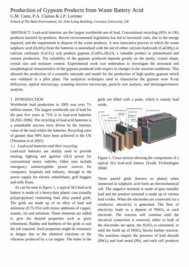
Production of Gypsum Products from Waste Battery Acid G.M. Cann, P.A. Claisse & J.P. Lorimer School of The Built Environment, Sir John Laing Building, Coventry University, UK ABSTRACT: Lead-acid batteries are the largest worldwide use of lead. Conventional recycling (95% in UK) produces harmful by-products. Recent environmental legislation has led to increased costs, due to the energy required, and the requirement to dispose of the waste products. A new innovative process in which the waste sulphuric acid (H 2 SO 4 ) from the batteries is neutralised with the aid of either calcium hydroxide (Ca(OH) 2 ) or calcium carbonate (CaCO 3 ) will produce gypsum (CaSO 4 .2H 2 O), a valuable product in plasterboard and cement production. The suitability of the gypsum produced depends greatly on the purity, crystal shape, crystal size and moisture content. Experimental work was undertaken to investigate the structural and morphological characteristics of the gypsum produced with respect to changes in the reaction conditions. This allowed the production of a scientific rationale and model for the production of high quality gypsum which was validated in a pilot plant. The analytical techniques used to characterise the gypsum were X-ray diffraction, optical microscopy, scanning electron microscopy, particle size analysis, and thermogravimetric analysis. 1 INTRODUCTION Worldwide lead production in 2005 was over 7½ million tonnes. The largest worldwide use of lead for the past five years at 71% is in lead-acid batteries [ILZSG 2006]. The recycling of lead-acid batteries is a remarkable success story driven by the intrinsic value of the lead within the batteries. Recycling rates of greater than 90% have been achieved in the UK [Thornton et al 2001]. 1.1 Lead-acid batteries and their recycling Lead-acid batteries are mainly used to provide starting, lighting and ignition (SLI) power for conventional motor vehicles. Other uses include emergency uninterruptible power sources for computers, hospitals and industry, through to the power supply for electric wheelchairs, golf buggies and milk floats. As can be seen in figure 1, a typical SLI lead-acid battery is made of a heavy-duty plastic case (usually polypropylene) containing lead alloy pasted grids. The grids are made up of an alloy of lead and antimony (0.75-5%) with minor additions of copper, arsenic, tin and selenium. These elements are added to give the desired properties such as grain refinement, fluidity and hardness of the grids to suit the job required. Such properties might be resistance to fatigue due to the chemical reactions or the vibration produced by a car engine. The holes in the grids are filled with a paste, which is mainly lead oxide. Figure 1. Cross-section showing the components of a typical SLI lead-acid battery [Exide Technologies 2004] These pasted grids (known as plates) when immersed in sulphuric acid form an electrochemical cell. The negative terminal is made of grey metallic lead and the positive terminal is made up of various lead oxides. When the electrodes are connected via a conductor, electricity is generated. The flow of electricity leads to a deposit of PbSO 4 at each electrode. The reaction will continue until the electrical connection is removed, either or both of the electrodes are spent, the H 2 SO 4 is consumed, or until the build up of PbSO 4 blocks further reaction. The reactions require the presence of lead dioxide (PbO 2 ) and lead metal (Pb), and each cell produces
Transcript of Production of Gypsum Products from Waste Battery Acid papers/Conference 37.pdf · Production of...
Production of Gypsum Products from Waste Battery Acid G.M. Cann, P.A. Claisse & J.P. Lorimer School of The Built Environment, Sir John Laing Building, Coventry University, UK ABSTRACT: Lead-acid batteries are the largest worldwide use of lead. Conventional recycling (95% in UK) produces harmful by-products. Recent environmental legislation has led to increased costs, due to the energy required, and the requirement to dispose of the waste products. A new innovative process in which the waste sulphuric acid (H2SO4) from the batteries is neutralised with the aid of either calcium hydroxide (Ca(OH)2) or calcium carbonate (CaCO3) will produce gypsum (CaSO4.2H2O), a valuable product in plasterboard and cement production. The suitability of the gypsum produced depends greatly on the purity, crystal shape, crystal size and moisture content. Experimental work was undertaken to investigate the structural and morphological characteristics of the gypsum produced with respect to changes in the reaction conditions. This allowed the production of a scientific rationale and model for the production of high quality gypsum which was validated in a pilot plant. The analytical techniques used to characterise the gypsum were X-ray diffraction, optical microscopy, scanning electron microscopy, particle size analysis, and thermogravimetric analysis. 1 INTRODUCTION Worldwide lead production in 2005 was over 7½ million tonnes. The largest worldwide use of lead for the past five years at 71% is in lead-acid batteries [ILZSG 2006]. The recycling of lead-acid batteries is a remarkable success story driven by the intrinsic value of the lead within the batteries. Recycling rates of greater than 90% have been achieved in the UK [Thornton et al 2001]. 1.1 Lead-acid batteries and their recycling Lead-acid batteries are mainly used to provide starting, lighting and ignition (SLI) power for conventional motor vehicles. Other uses include emergency uninterruptible power sources for computers, hospitals and industry, through to the power supply for electric wheelchairs, golf buggies and milk floats. As can be seen in figure 1, a typical SLI lead-acid battery is made of a heavy-duty plastic case (usually polypropylene) containing lead alloy pasted grids. The grids are made up of an alloy of lead and antimony (0.75-5%) with minor additions of copper, arsenic, tin and selenium. These elements are added to give the desired properties such as grain refinement, fluidity and hardness of the grids to suit the job required. Such properties might be resistance to fatigue due to the chemical reactions or the vibration produced by a car engine. The holes in the
grids are filled with a paste, which is mainly lead oxide.
Figure 1. Cross-section showing the components of a typical SLI lead-acid battery [Exide Technologies 2004] These pasted grids (known as plates) when immersed in sulphuric acid form an electrochemical cell. The negative terminal is made of grey metallic lead and the positive terminal is made up of various lead oxides. When the electrodes are connected via a conductor, electricity is generated. The flow of electricity leads to a deposit of PbSO4 at each electrode. The reaction will continue until the electrical connection is removed, either or both of the electrodes are spent, the H2SO4 is consumed, or until the build up of PbSO4 blocks further reaction. The reactions require the presence of lead dioxide (PbO2) and lead metal (Pb), and each cell produces
cbx054
Text Box
For citation information please see http://www.claisse.info/Publish.htm
approximately 2V. The reactions are reversible and thus the battery can be recharged using a direct current.
The properties of lead make it ideal for use in batteries because it has good electrical conductivity and is resistant to corrosion. Lead is actually a very reactive metal, but it is this reactivity itself, which makes it resistant to corrosion. In sulphuric acid, lead metal reacts to form a protective layer of lead sulphate (PbSO4), which is tightly adherent and itself insoluble in sulphuric acid. Thus the lead underneath the lead sulphate layer is protected from any further attack. RHS: PbO2(s) + 4H+ + 2e- → Pb2+ + 2H2O (1.68V)
Pb2+ + SO4 2- → PbSO4(s)
LHS: PbSO4 + 2e- → Pb(s) + SO4 2- (-0.41V)
Overall: Pb + PbO2 + 2H2SO4 → 2PbSO4(s) + 2H2O (2.09V) Recycling of lead-acid batteries requires the batteries to be broken up using a battery-breaking machine. The battery-breaking machine either removes only the acid, or it separates the batteries into their components (i.e. the pastes, grids, separators and broken cases are collected in different hoppers and the acid is drained off). The breaking method used depends on the furnace used e.g. an Isasmelt furnace requires complete separation of the components whereas a shaft furnace smelts the batteries whole after the acid has been removed. The polypropylene cases can be cleaned and reprocessed to make recycled plastic to be used for example in new battery case production. Other polymeric components present (PVC, ebonite, terylene, fibreglass) are either landfilled or used as a reductant in the smelting process. The drained acid is neutralised and disposed of, some examples of which are listed below:
H2SO4 + 2NaOH → 2H2O + Na2SO4
H2SO4 + Ca(OH)2 → CaSO4.2H2O H2SO4 + CaCO3 + H2O → CaSO4.2H2O + CO2
The pastes and grids are smelted in a furnace. Traditionally this was done in a blast furnace,
although they have recently gone out of favour due to the high costs of metallurgical coke and the difficultly of collecting the dust and fume. Nowadays it is more common to use a rotary furnace or an Isasmelt furnace. The rotary furnace is used as a one-stage process with the feed adjusted to give a lead with the desired properties or as a two-stage process producing a soft lead and an antimonial lead. With the two-stage process, during the first stage, the furnace conditions are kept such that all the antimony is oxidized while the lead is not. The antimony oxides are not soluble in lead so the molten lead metal can be removed leaving the lead oxide and sulphate within the antimonial slag. Stage two involves the addition of coke or anthracite fines and sodium carbonate to the furnace. This leads to the reduction of the lead and antimony oxides and the lead sulphate. An antimonial lead and a slag are produced which are refined and disposed of respectively. The Isasmelt furnace is fed with battery paste that has been desulphurised, typically to a lead oxide paste or to lead carbonate.
PbSO4 + 2NaOH → PbO + Na2SO4 + H2O PbSO4 + Na2CO3 → PbCO3 + Na2SO4
A lance is used to melt the desulphurised paste. For 36 hours the furnace is fed with wet paste and coal as a reductant. Every three hours lead of 99.9% purity is tapped off. As the process continues, the lead content of the slag falls as the impurity levels rise. The lance keeps the slag fluid by raising the temperature from 900oC to 1000oC during the process. After 36 hours, no more paste is added to the furnace and the remaining slag is reduced to produce an antimonial lead alloy. This occurs over two hours during which time the temperature is raised to 1200oC and fluxes are added. When the reduction is complete the lance is removed, the antimonial lead alloy (containing >98.5% lead and antimony) is tapped off and the remaining slag is discarded (containing <0.5% lead).

Similarly to the rotary furnace, off gases are cooled and filtered for dust particles. The battery grid metal is melted in a separate furnace. The advantages of this process over the rotary furnace are a higher thermal efficiency and therefore lower running expenses, the omission of soda fluxes, the direct production of soft lead and antimonial lead alloy, production of waste slags having low lead concentrations, and the improved process hygiene since the process is semi-continuous. A disadvantage of the process is that when the pastes are desulphurised before smelting, a waste solution of sodium sulphate is produced which requires disposal. Secondary lead is then refined in kettles after it has been collected from the smelter. The main impurities present that need to be removed are copper, tin, antimony and arsenic. The final lead produced will be 99.99% pure or even 99.9999% with extra treatment. A diagram of the main processes involved and the volumes of products/waste streams for a typical conventional battery recycling plant are shown in figure 2. 1.2 The Cleanlead Project As can be seen in figure 2, the secondary lead industry produces acidic sludge from the neutralised waste acid, sodium sulphate if the pastes are desulphurised, leachable toxic slags and vast amounts of exhaust gases containing SO2 and metal fume. Due to recent environmental legislation, costs have increased substantially due to: (i) the necessity to dispose of the waste produced and (ii) the energy required. Therefore the secondary lead industry is becoming uneconomical. It is feared that this will lead to a reduction in the recycling rates of lead-acid batteries unless alternative economical and zero waste production methods are developed. A new zero waste process has been proposed for the secondary lead industry (see figure 3) and has been designed so that it can either optimise the current processes, or it can easily be added to existing plant to make it more cost effective for industry.
One of the proposals for the new process is that instead of neutralizing the acid to produce a waste acidic sludge, it was proposed that the acid is purified. This will take place either by solvent extraction, absorption resins, membrane techniques (e.g. reverse osmosis, nanofiltration, electrodialysis) or bio-reduction. The purified acid can then be used to refill new lead-acid batteries, or neutralised with Ca(OH)2 or CaCO3 under controlled conditions to produce high quality gypsum products for use in industry. Rather than desulphurisation of the battery paste with sodium hydroxide producing the waste sodium sulphate solution, it was proposed that lime is added to the waste Na2SO4 solution. This will produce a clean gypsum product, which is saleable and also regenerate the NaOH leachant, thus creating no wastes.
PbSO4 + 2NaOH ⇔ Pb(OH)2 + Na2SO4
Na2SO4 + Ca(OH)2 ⇔ 2NaOH + CaSO4
Conventionally spent batteries are processed pyrometallurgically producing toxic slags that are land filled. In this new process, the pastes are fully desulphurised which means the furnaces will produce ferro-silicate based slags (and also less slag). Ferro-silicate slags are non-hazardous and are usable as an alternative to other raw materials e.g. as an aggregate in concrete. The desulphurisation of the pastes would also eliminate the generation of sulphur dioxide exhaust gases directly from the batteries.
A new lead electrolytic process has been proposed to produce 99.99% pure lead whilst using less energy (0.5 kWh/kg Pb) in an environmentally friendly alkaline media. This would replace the conventional battery paste smelting stages, which are the main waste generators and are energy intensive. The desulphurised paste (mainly PbO) is to be dissolved in alkaline media, where lead has a high solubility whereas the metallic impurities have a low solubility.
PbO + 2NaOH + H2O → PbNa2(OH)4

To prevent the passing of any impurities into the electrolyte and thus co-deposited with the lead, a counter-current leaching stage will be used. This is intended to reduce the amount of impurities such as antimony, copper, arsenic, and tin in the electrolyte. The purified electrolyte will electrodeposit 99.99% pure lead on the cathode in an electrowinning cell while oxygen will be released at the anode. Cathode: PbNa2(OH)4 + 2e- → Pb0 + 2NaOH + OH-
Anode: 2OH- - 2e- → ½O2 + H2O Overall: PbNa2(OH)4 → Pb0 + ½O2 + 2NaOH + H2O “The complete new process will use minimal energy, virtually no raw materials, generate zero waste and
consequently greatly reduce the operating cost [CORDIS 2004].”
The role of the author within the Cleanlead consortium was to develop a high quality synthetic gypsum by neutralising the waste battery acid.
Ca(OH)2 + H2SO4 → CaSO4.2H2O CaCO3 + H2SO4 + H2O → CaSO4.2H2O + CO2
1.3 Gypsum Gypsum is a naturally occurring mineral used in a wide variety of industrial applications. These include in plasterboard, as a set-controlling additive in cement and as a soil conditioner in agriculture. Each industrial end use requires a different specification gypsum.
Figure 2. Typical lead-acid battery recycling plant showing volumes of wastes created

Figure 3. Proposed Cleanlead Factory showing zero waste streams
The chemical name of gypsum is calcium sulphate dihydrate. Calcium sulphate exists in a number of compounds with the general formula CaSO4.xH2O (where x varies from 0 to 2). The most common forms are where x = 2 (gypsum, “alabaster”, “selenite”, etc.), x = 0.5 (bassanite, “α- or β-hemihydrate”, “stucco”), and x = 0 (“anhydrite”).
Two forms of hemihydrate, α and β [Hand 1997], have been accepted with some controversy. The α-form is produced by dehydrating dihydrate gypsum at temperatures higher than 97oC in an atmosphere of saturated steam (autoclaving), or by exposing dihydrate gypsum to high concentration inorganic
salt solutions or dilute sulphuric acid [Zurz et al 1991, Othmer 1992].
The β-form of hemihydrate is produced, by dehydrating (calcining) dihydrate gypsum without an atmosphere of saturated steam. A device called a calciner is typically used and these vary between direct, indirect, batch and continuous processes.
Typical calciners used industrially include the kettle calciner and the flash calciner. A kettle operates by passing hot air through pipes which run across the kettle chamber. Inside, the ground gypsum is added by an inlet at the bottom. The gypsum then loses its water of crystallisation and converts into hemihydrate. The steam provides some agitation of the powders, keeping the system fluidised, and the

“stucco” produced will rise to the top (the product being less dense than the starting material), where it overflows into a receptacle.
Kettle temperatures are adjusted depending on the exact hemihydrate requirements or on the actual kettle set-up, but typically are around 104oC during the fill cycle. Upon filling, the kettle is heated for an hour to 115-120oC to remove any free moisture. After this time, known as the boil or the drag, the temperature of the gypsum is increased to 150-155oC to form β-hemihydrate. Early kettle types were batch, indirect processes, but now modern varieties exist which are direct and continuous.
A flash calciner operates as a continuous direct process with rock gypsum being introduced into a ball mill and the dust produced immediately passing through a very high temperature air stream for a few seconds, which is sufficient for complete dehydration to stucco. Flash calciner stucco rapidly rehydrates back to the dihydrate when mixed with water (i.e. has a quick setting time) and is thus particularly suited for use in the plasterboard industry. The process has a disadvantage over kettles in that it is not suitable for synthetic gypsum.
Anhydrite occurs in three distinct forms, anhydrite I, anhydrite II, and anhydrite III [Hand 1997]. Anhydrite II is the common rock form found naturally in nature and is also formed from the high temperature (~900oC) dehydration of gypsum. It is often referred to as insoluble, natural or ‘deadburn’ gypsum due to its inertness and thus it does not rehydrate on an industrially viable timescale. Anhydrite III is formed from the low temperature (140-200oC) dehydration of α - or β -hemihydrate; its trivial names include ‘soluble’ and ‘overburn’, and it is a component of freshly prepared stucco. It has the same crystal lattice as hemihydrate and therefore readily absorbs moisture from the atmosphere to revert back to hemihydrate. It is sold as a highly potent and reactive desiccant Drierite™. Finally, anhydrite I is derived from the over-calcination of anhydrite-II. It is unstable at temperatures below 900oC, hence not much is known with certainty about this material. Above
approximately 1200oC, it decomposes into CaO and SO3. 1.4 Gypsum Uses Figure 4 shows that the three largest markets for
European use of gypsum are plasters, plasterboard and cement (where plasters are defined as commercially available bagged powder gypsum products used for applications as diverse as making sculptures through to plastering walls). Figure 4. European gypsum use in 2000 [Lafarge Platerboard 2000] The formulation of plasters and their use on-site are region-specific. Often, plasters have been mined locally for a long time and the natural gypsum often has characteristic properties which are difficult to replicate with a synthetic material. This means that there is no uniform specification for plasters and they are therefore not being considered as an end use of the Cleanlead gypsum produced.
This leaves plasterboard and cement as the two main targets for end uses of Cleanlead gypsum. Other uses to be considered include use as a self-levelling floorscreed or as a soil re-conditioner in agriculture.
Gypsum is traditionally supplied from quarries or mines, but these sources are being increasingly replaced with by-product gypsum, primarily from flue-gas desulphurisation (FGD) plants at power stations [Ng (no date), EPRI (USA) 1994]. Other synthetic gypsums are manufactured such as titanogypsum, a by-product from the manufacture of anatase titanium dioxide [Albrecht (no date)], fluoroanhydrite, a by-product from the manufacture of hydrofluoric acid, phosphogypsum, a by-product from the manufacture of phosphoric acid mainly for
Plasters36%
Cement29%
Other3%
Plasterboard32%

Aerated gypsum core
Paper Bond at Gypsum/Paper interface
Paper
the fertilisers industry, citrogypsum, tartarogypsum and lactogypsum, by-products from the manufacture of organic acids, and borogypsum, a by-product from the manufacture of boric acid.
It is anticipated that the major problems, which may occur with Cleanlead gypsum are similar to those encountered with FGD gypsum, titano-gypsum and other synthetic gypsums. These problems relate to impurities, particle size and morphology with respect to the conditions of manufacture [Ng (no date), EPRI (USA) 1994, Albrecht (no date), Park and Parrow (no date)].
Analytical techniques available to characterise the gypsum samples were X-ray diffraction (XRD), optical microscopy, particle size analysis, thermogravimetric analysis (TGA) and bulk property analysis (for example the apparent density of the sample). These techniques were chosen because they allow the gathering of all of the data required to check the quality and suitability of the gypsum produced for use in different industrial applications.
The modern plasterboard factory runs as a continuous process applying a layer of gypsum slurry to a bottom layer of paper before a top sheet of paper is applied (see figure 5).
Initially the milled gypsum (natural mined rock gypsum, synthetic gypsum, or a blend of both) is calcined from the dihydrate phase to the hemihydrate phase by heating. CaSO4.2H2O + Δ ⇔ CaSO4.½H2O + 1½H2O The hemihydrate plaster is then mixed with water and the required additives to control the setting of the plaster (such as starch, accelerators and retarders). This plaster slurry is then applied between two layers of paper lining. The hemihydrate plaster now hydrates back to the dihydrate phase with the gypsum crystals growing between the paper fibres and forming the “wet bond”. The plasterboard is then dried in ovens to remove any excess free water and the mechanical bond between the gypsum core and the paper is the only bond which prevents the paper from being separated in the drier. It is for this reason that stringent specifications exist on
impurities which are known to disrupt this bond, the principal of these being chloride and soluble cations such as sodium and magnesium.
Figure 5. (Top photo) gypsum slurry is applied to the bottom sheet of paper and then the top sheet of paper is applied (bottom photo).
A simplified cross-sectional diagram of a sheet of plasterboard is shown in figure 6. Typically plasterboard is 12.5mm thick and weighs 8.5kg/m2. Figure 6. Plasterboard structure
During the drying process, the starch blended into the slurry dissolves, forms a gel by absorbing approximately thirty-fold of its weight in water, and migrates to the paper interface, where the water evaporates. In this process, the starch gel forms a coating over the gypsum crystals, thereby providing protection of the gypsum core, and in particular the paper-gypsum interface against calcination and bond failure. After completion of the drying, the starch re-precipitates, and forms in conjunction with the
gypsum crystals the “dry bond”, which is hydrogen-bonding between the cellulose and starch molecules.
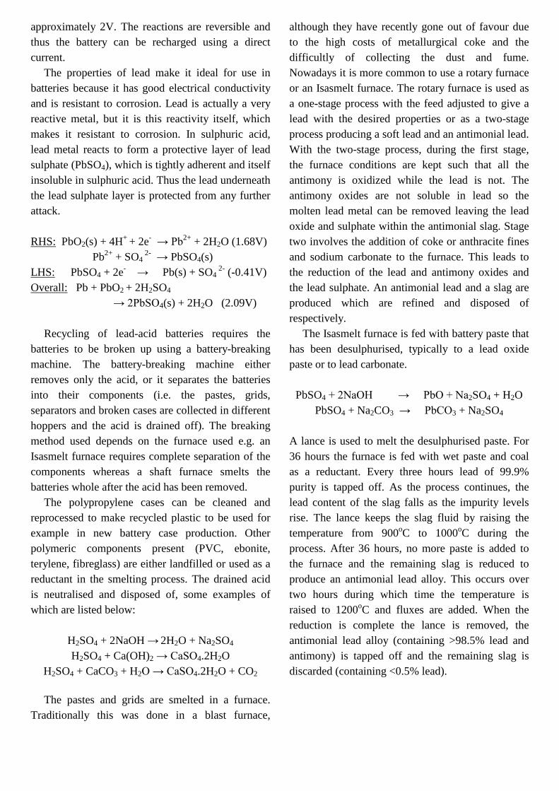
The gypsum-paper mechanical bond is negatively affected by all attempts to improve the economy of the plasterboard production. Using less gypsum to reduce the cost of the plasterboard and hence having a lower board weight leads to there being less gypsum and more air at the gypsum/paper interface. This reduction in the amount of gypsum at the gypsum/paper interface weakens the mechanical bond because there is less gypsum crystal growth into the paper upon hydration.
If the board production line speed is increased to speed up production, the gypsum hemihydrate slurry between the paper sheets does not have time to fully rehydrate to dihydrate before being dried. This leads to a poorer mechanical bond as not all of the hemihydrate rehydrates to dihydrate whose crystals grow into the paper fibres to create the mechanical bond.
Less water can be added to the gypsum slurry to improve economy; this has two effects. Firstly the board dries quicker and thus the board production line can be run faster. Secondly, it decreases the drying energy costs (and thus CO2 emissions). Unfortunately the use of less water leads to slower and incomplete hydration of the hemihydrate, which leads to a poorer mechanical bond due to there being less dihydrate crystals growing into the paper fibres.
The mechanical bond is the most important factor in plasterboard production and the quality of the finished product. The quality of the gypsum used and in particular, the particle size has a very large effect on the mechanical bond. Figure 7 shows a simplistic consideration assuming spherical particles of the crystal packing at the gypsum/paper interface.
When the particle size distribution is spread over a wide range, there is greater intimacy between the gypsum particles and the paper i.e. there are fewer gaps and smaller. This means that more gypsum crystals can grow into the paper fibres and hence the mechanical bond is greater. A narrow distribution of particle sizes is undesirable as the space filling of the particles would be poor. This is because uniform size round particles leave gaps between themselves.
Poor Optimum Figure 7. Crystal packing at the gypsum/paper interface. The spheres indicate gypsum crystals and the shaded area is the paper.
The specification for particle size is usually
quoted as the median particle size (d50). For use in plasterboard the optimum d50 is 30 - 80 μm [Lafarge Plasterboard 2001]. As can be seen from figure 7, ideally the particle size distribution would be bimodal to give a good particle size spread (with a peak at around 30 μm and another at 80 μm) to leave fewer gaps between the crystals. Particle size distribution also affects storage and handling since fine dust like powders are difficult to transport and handle on conveyor belts and hoppers. In the traditional plasterboard plant natural gypsum is supplied as rocks, which are easier for the machinery to handle, although these have to be finely milled before or during calcination.
Any traditional plasterboard factory running on a source of natural gypsum, and wishing to use synthetic gypsum such as desulphogypsum (DSG) from FGD plants, needs to either use a facility that converts the moist, paste-like synthetic gypsum into a dry rock-like material, or (as is often more economically viable) invest in a change of gypsum raw material storage and handling, calcination and milling equipment. It should be remembered that there are health implications associated with handling fine dust like powders.
Particle size also affects the water demand of the gypsum because both smaller and larger particles demand more water (i.e. more water has to be added to the hemihydrate in the slurry). Smaller particles have a greater surface area whereas larger particles have gaps between the crystals which fill with water

upon hydration. Thus the drying time increases since more free water must be removed from the finished plasterboard in the ovens (increasing energy costs and CO2 emissions).
The soluble ion content within the gypsum is important as well. Sodium and chloride ions particularly, and others also to a lesser extent, interfere with the hydration of the hemihydrate during plasterboard production. This weakens the gypsum/paper mechanical bond. The presence of some ions can also lead to aesthetic defects in the gypsum products such as staining of plasterboard.
Trace impurities and in particular heavy metals in the gypsum produced also need to be monitored. These trace impurities have no effect on the plasterboard produced but they need to be minimised so as to be within limits imposed by the EU Construction Products Directive in relation to harmful substances [1989].
In addition to the difficulties with handling dry powders, another handling problem with synthetic gypsum is the free water content of the received material. If the moisture content (MC) is greater than 10%, the gypsum is ‘sticky’ and therefore difficult to handle due to sticking to conveyor belts and hoppers. The maximum permitted MC tolerated by the plasterboard industry is 12% [Lafarge Plasterboard 2001]. A higher %MC increases transportation costs because it is necessary to pay for the transportation of more water. Market reports suggest that 50-90% of the delivered cost to the user of the gypsum is due to transportation costs [Lafarge Plasterboard 2000]. To make matters worse, when the high %MC gypsum arrives at the plasterboard factory, more energy is required to calcine the gypsum to hemihydrate because the excess free water must be removed.
The shape of the gypsum crystals themselves has important implications on the quality of the stucco produced. The effect of crystal shape is similar to the effect of the particle size distribution. This is because acicular (needle) shaped crystals negatively affect the quality of plasterboard produced. Round shaped crystals will pack closely, whereas acicular shaped crystals pack poorly. The poor packing of the
acicular shaped crystals leads to a higher water demand in a similar way as an out of specification particle size distribution would. The higher water demand leads to higher drying costs and weaker paper gypsum bonding. Also the poorer space filling of the acicular shaped crystals (similar to that of the narrow particle size distribution in figure 7) leads to a weaker mechanical bond at the gypsum/paper interface. An acicular crystal is defined by industry as a crystal with a length three times or greater than its width [Lafarge Plasterboard 2001]. Acicular shaped crystals also have a tendency to interlock with each other which leads to difficulties with storage and processing as they block silos and hoppers.
The use of optical and scanning electron microscopes is useful since they provide detail of the crystal shapes and also further insight into the particle size distribution. The bulk properties such as apparent bulk density of the gypsum samples can also provide a measure of the extent of the presence of acicular crystals. The apparent bulk density of a gypsum sample can be calculated by weighing a known volume of gypsum. Acicular crystals will pack poorly because gaps will be left between the crystals and will therefore have a lower apparent density. A sample with an apparent density greater than or equal to 1kg/litre is deemed to be acceptable for industrial use [Lafarge Plasterboard 2001]. A high apparent density is important for the gypsum also to reduce transportation costs.
An important consideration for synthetic gypsum is the angle of repose of the gypsum in the store warehouse. The angle of repose is the angle formed between the ground and gypsum from the stacking process in the warehouse where it is stored. The gypsum enters the warehouse on a conveyor belt at the top of the pile dropping it so that it stacks naturally. Natural gypsum has an angle of repose of 45o whereas synthetic gypsum has an angle of repose of 60o - 80o. Figure 8 shows the problem caused by the synthetic gypsum angle of repose. It can be seen that if synthetic gypsum is incorporated into a warehouse designed for natural gypsum where the roof slopes at an angle of 45o, there is wasted room

and hence less capacity. This will reduce the economy of the manufacturing process.
If the synthetic gypsum is briquetted (see figure 9), the angle of repose can be improved. This is because the briquettes produced will be similar in shape to natural rock gypsum.
For use in plasterboard it is clear that the Cleanlead gypsum will have to be dihydrate gypsum. To produce pure β-hemihydrate from the Cleanlead process would be an advantage because calcining costs would be eliminated. Although if β-hemihydrate is manufactured from Cleanlead technology, it has to be at least 95% pure because the presence of any dihydrate gypsum or anhydrite will lead to a poor mechanical bond as these crystals will not “grow” into the paper fibres. The presence of dihydrate in β-hemihydrate is a particular problem due to the fact that β-hemihydrate will naturally re-hydrate back to dihydrate absorbing moisture from the atmosphere. Therefore all β-hemihydrate has a limited shelf life, which is a maximum of 6 months if stored under optimum ‘dry’ conditions. X-ray Diffraction (XRD) is a technique used to determine which phases of gypsum are present in a gypsum sample (although XRD cannot distinguish between α and β hemihydrate [Hand 1997]). The plasterboard industry requires a minimum purity of 95% CaSO4.2H2O in its secondary gypsum. Thermogravimetric (TG) data can also be used to determine the phases present by recording the mass lost upon heating of a sample which corresponds to the calcinations of the water of crystallisation (although TG analysis cannot distinguish between α and β hemihydrate or anhydrite I, II and III).
Figure 8. The angle of repose for natural (45o) and synthetic gypsum (60 - 80o) for a warehouse filled from an overhead conveyor belt and supported by a wall on either side.
Figure 9. An example of a DSG briquette.
An alternative industrial use for Cleanlead
gypsum would be in the cement industry, which adds between 3% and 8% gypsum as an additive to cement when the cement clinker is being ground. Gypsum is added to cement to control the setting time for the cement. Tricalcuim aluminate, one of the 4 main components of cement, reacts rapidly with water causing the cement to ‘flash set’ within minutes. Gypsum controls the setting time of cement by hydrating with tricalcium aluminate to form an alumino-sulphate mineral (called ettringite) coating on the surface of the tricalcium aluminate preventing further hydration [Bye 1983].
The gypsum is added to the grinding mills as the dihydrate form with anything up to 70% anhydrite so as to alter the setting times of the cement due to the solubilities of the various gypsum phases depending on the manufacturer’s requirements. For example, anhydrite II is less soluble than dihydrate. It is important that there is no hemihydrate present in the cement, otherwise the hemihydrate could hydrate to dihydrate and harden on hydration of the cement causing ‘false set’.
Gypsum also has other effects in cement production such as it acts as a grinding aid in the ball mill [Bye 1983]. It also has an effect on the expansion of the cement and can stop cement shrinking on setting. Conversely it can cause negative effects such as excessive expansion and therefore cracking upon setting.
60 - 80o
45o

Cement has stringent limits on the presence of alkalis such as sodium and potassium due to the alkali silica reaction in concretes containing certain reactive silica aggregates, which leads to cracking of the concrete. Other impurities of concern are the chloride content which can attack and rust the steel in reinforced concrete leading to cracking. Therefore all gypsum samples must contain minimal levels of sodium, potassium and chloride. Other uses include the use of gypsum as a floorscreed. In the majority of modern construction, floorscreeds are manufactured from a concrete product. Standard concrete floorscreeds are not self-levelling and thus need to be carefully applied and skilfully levelled out. A newer approach is to use gypsum, which is self-levelling. This means that the need for expensive finishing work is no longer required and the products rapid strength means that workers are able to walk on it more quickly relative to concrete (48 hours for gypsum compared with weeks for concrete) and are thus able to carry on with their work. The gypsum binder is mixed with sand, other aggregates and water, then applied to the floor and encouraged to fill the entire room. The gypsum used is either anhydrite-II or α-hemihydrate. Anhydrite-II can be delivered as a ready-mixed slurry as it is workable for 5 hours. The setting time and strength of the floor can be adjusted by changes to the formulation and is done at the request of the customer by the producer of the anhydrite binder. α-hemihydrate is mixed in the same manner as anhydrite-II (i.e. with sand, aggregates and water) though the user carries out the mixing on-site as the setting time is approximately 30 minutes. It is unlikely that Cleanlead gypsum could be used as a floor screed as anhydrite II cannot be manufactured directly from the Cleanlead process. There is a patented process which is used to calcine DSG to anhydrite II in a continuous flash process. It is anticipated that small proportions of the feedstock into this Rocal® process could be synthetic gypsum other than DSG.
The least economically viable use of the Cleanlead gypsum would be in agriculture as a soil conditioner. Gypsum is an excellent soil re-
conditioner for many reasons. It is a good source of calcium and sulphur, which are the seventh and ninth most important of the 16 essential nutrients for plants [North Pacific AG Products 2004]. Gypsum slowly dissolves in the moisture present in soils, which allows plants roots to absorb calcium ions and sulphate ions. As well as being an essential nutrient, calcium helps plant roots in the uptake of other minerals. Other advantages of gypsum as a soil re-conditioner are its ability to reclaim high sodium soils. Soils containing an excess of Na+ ions lose structure and pack tightly so that it is difficult for water and air to reach the roots. When gypsum is applied, calcium ions replace the sodium ions in the soil and the sodium is washed away as sodium sulphate.
Gypsum is pH neutral and thus has little affect on soil pH. It can be used to reduce the pH of alkaline soils, which contain bicarbonate ions (HCO3
-). Ca2+ + 2 HCO3
- → CaCO3 + CO2 + H2O
Calcium dissolved into the soil from gypsum as Ca2+ will react with the bicarbonate to form insoluble calcium carbonate thus reducing the pH (although at a relatively slow rate under ambient temperature conditions). Application of gypsum to soils has also been shown to reduce the uptake of heavy metals (and Al) in plants.
To use Cleanlead gypsum in agriculture as a soil re-conditioner, the gypsum can be low quality with no requirements for particle size, crystal shape or morphology. The only specification for gypsum for use in agriculture is restrictions on heavy metal composition for the obvious toxicity implications of heavy metals passing into the food chain [MAFF 1998]. 2 EXPERIMENTAL 2.1 Initial Experiments Initially a series of bench scale batch reactions were performed to assess the parameters which had the greatest influence on the quality of the gypsum produced.

These experiments were performed using synthetic reagents i.e. sulphuric acid and calcium hydroxide or calcium carbonate.
Early experiments added Ca(OH)2 powder to neutralise the H2SO4 to a target pH of 7. The rate of powder addition, filtration method and drying temperature were varied. It was noted that the reactions were difficult to control when adding the neutralising agent as a dry powder to the sulphuric acid, so for all subsequent reactions the Ca(OH)2 or CaCO3 was added as a slurry.
The following parameters were varied throughout the initial phase of experiments: – Ca(OH)2 or CaCO3 – Ca(OH)2/CaCO3 added as powder or slurry – H2SO4 concentration (g/dm3) of 108, 101 and
38.1 – H2SO4 analytical or doped with metals to ‘model
acid concentration’ – Target final pH of 2, 4 and 7 – Reaction temperature of 20oC, 60oC and 80oC – Reaction time (hours) of 1 , 2 and 4 – Filtration method of vacuum or pressure – Drying method of 21oC, 50oC, 70oC, 100oC and
Isopropanol/Ethanol 2.2 Further Experimentation These later experiments saw a shift to larger scale reactors and continuous or semi-continuous processes employing peristaltic pumps.
The following parameters were varied throughout these later experiments: – Ca(OH)2 or CaCO3 – Two different commercial CaCO3’s – Ca(OH)2/CaCO3 slurry concentration (g/dm3) of
75, 200, 350 and 500 – H2SO4 concentration (g/dm3) of 100, 110, 114
and 120 – H2SO4 analytical, doped with metals to ‘model
acid concentration’ and waste battery acid – Target final pH of 2, 3, 4 and 6 – Reaction temperature of 40oC and 60oC – Retention time (hours) of 1 , 2 and 3 – Reactor solids density (g/dm3) 79, 126, 128, 133,
146, 153 and 164 – Addition of gypsum crystals to seed reaction
– Hydrocycloning gypsum pulp to return fines to reactor as seeds
– Mixer speed (rpm) of 1240, 1400, 1650 and 1900 – Filtration method of vacuum or pressure – Drying method of 21oC, 40oC, 50oC, 80oC and
100oC As the experiments were continuous rather than batch, the times listed above are retention times in the reactor rather than total reaction time as in Section 2.1. 2.3 Pilot Plant Finally, three Cleanlead gypsums were produced separately in a large pilot plant from three different waste battery acid streams using commercial quality limestone. These experiments were carried out after over 150 different gypsum samples had been prepared in the previous experiments and subsequently analysed.
The pilot plant consisted of a 300dm3 reactor with a heating element and a high speed agitator designed to exert high shear forces on the reactants. Sulphuric acid and limestone slurry (500g/dm3) were pumped continuously into the reactor and the gypsum pulp with a reactor retention time of 2 hours was pumped out periodically. The collected gypsum pulp was passed through a hydrocyclone system twice with the first stage underflow collected as product and the second stage underflow collected and returned to the reactor to act as gypsum seeds. The pilot plant is shown in figure 10.
The three Cleanlead gypsums were produced from untreated contaminated battery acid, nanofiltration treated contaminated battery acid and diffusion dialysis treated contaminated battery acid. 3 RESULTS All gypsums produced were analysed to determine the crystal shape, size, phase (and purity) and moisture content where possible.
All gypsums samples analysed by XRD and TG analysis were high purity (>95%) gypsums. However, the drying temperature of the samples had a significant affect on the gypsum phase produced. For all samples dried at 50oC or less, the samples were dihydrate gypsum.

Figure 10. Final gypsum pilot plant
Samples dried at 70oC varied between samples containing only dihydrate, samples containing mainly dihydrate with a trace of hemihydrate and finally samples that contained more hemihydrate than dihydrate. An example of the XRD spectra of some samples dried to constant mass at 70oC can be seen in figure 11. Samples dried at 80oC contained a majority of hemihydrate with some dihydrate. Samples dried at 100oC tended to contain almost exclusively hemihydrate.
It should be noted that prior to analysis, the samples were dried to constant mass at the specified temperature over a few days in temperature controlled ovens. Although, when pre-dried dihydrate samples were heated at relatively quick rates (5oC/min) in the TG balance, decomposition to hemihydrate and anhydrite would not start until at least 100oC or in some cases 120oC.
From these results it would appear that dihydrate gypsum begins to dehydrate at temperatures around 70oC if given enough time, otherwise it needs to be heated to over 100oC to dehydrate.
Analysis of the shape of the crystals showed that initially they were mainly acicular in nature although later experiments improved the shape towards the preferred more regular squat prismatic crystals. Figure 12 shows the improvement in crystal shape from an early sample to a sample produced on the pilot plant viewed under a scanning electron microscope. The negative effects of acicular crystals
on storage of gypsum were readily observed by the extremely low bulk densities of the early samples with bulk densities as low as 0.2 kg/dm3. The pilot plant gypsums fell short of the 1.0 kg/dm3 target, but still achieved 0.8 kg/dm3.
Another negative effect of the acicular crystals was the reduction in filtration efficiency associated with the poor packing of these crystals. As an example some early predominantly acicular samples had free moisture contents of over 40% whereas the final pilot plant samples were around 10% or less. Some of this improvement can be accounted in the change from vacuum filtration to pressure filtration.
The particle size distributions (PSDs) of the pilot plant gypsums were all at the lower end of the industrial specification of 30µm < d50 < 80 µm. Some earlier samples appeared to have the best PSDs, although this was generally due to the presence of very long thin acicular crystals as shown in figure 12.
A trend was noticed for samples from the same batch which had been dried at different temperatures to have smaller PSDs if they had begun to calcine from dihydrate to hemihydrate (confirmed by analysing the samples with XRD and TG analysis). High magnification analysis of these samples using a SEM showed that the crystals which were smooth and regular shaped were dihydrate whereas the samples containing dihydrate and hemihydrate had crystals which were fractured and rough (see figure 13). It is therefore likely that the shift in the PSDs of these samples to lower values was due to the ultrasonic dispersion mechanism in the laser particle size analyser dislodging the ‘flaky’ surface or even breaking some of the crystals. 4 INDUSTRIAL APPLICATION Following the optimisation of the gypsum production and the subsequent validating of the results in a pilot plant, the three gypsums produced were assessed for their suitability as feedstocks in the plasterboard and cement industries.
Samples of all three gypsums were sent to Lafarge Gypsum’s research laboratories in Avignon, France. Researchers at Lafarge analysed the quality of the gypsum produced and then produced samples
Acid
Reactor
Hydrocyclone

of plasterboard using the Cleanlead gypsums alone and at blends of 70% natural gypsum and 30% Cleanlead gypsum.
The gypsums were shown to be high purity but there were some issues with regards to the crystal shapes and their consequential higher water demands (compared with natural gypsum). It was shown that the optimum use of Cleanlead gypsum would be as part of a blend with natural gypsum at a ratio of 30% Cleanlead gypsum to 70% natural.
The three Cleanlead gypsums were assessed for their suitability at Coventry University by intergrinding the gypsums with cement clinker supplied by Lafarge Cement. The cements prepared were assessed by recording their setting times and 28 day strengths according to European Standards [EN196-1:1995, EN196-3:1995]. The gypsums all performed acceptably when compared to reference cements and gypsums. 5 CONCLUSIONS The Cleanlead project successfully generated gypsum that could be used within the plasterboard and cement industries.
Due to the comparatively low volumes of Cleanlead gypsum envisaged to be produced by a Cleanlead battery recycling factory, any gypsum
supplied to the Plasterboard industry would have to be blended with other gypsum as otherwise there would not be enough to supply a factory annually.
The same would be true with a cement factory or though to a lesser extent as a cement factory uses less gypsum.
Therefore producing Cleanlead gypsum as a by-product of SLI battery recycling helps make the secondary lead industry more sustainable by turning a waste stream into a valuable product. Also Cleanlead gypsum can help make both the plasterboard and cement industries more sustainable by reducing their reliance on mined natural gypsum, a finite resource. ACKNOWLEDGEMENTS The author would like to say a special thank you to Dr. Heven Abdul-Jabbar at Coventry University. Also many thanks to the researchers at Lafarge Plasterboard UK, Tecnicas Reunidas Madrid (Spain), Instytut Metali Niezelaznych Gliwice (Poland) as well as all other Cleanlead project partners who contributed to the success of this project.
0
50
100
150
200
250
0 10 20 30 40 50 60 70 80 90
2-theta (degrees)
Inte
nsity
(Squ
are
Roo
t)
GC16 dried 70CGC26 dried 70CGC45 dried 70C
HH
DH HH
DH
DH

Figure 11. XRD spectra of three different gypsum samples all dried at 70oC. The top sample contains only dihydrate (DH), the middle sample contains mainly DH with some hemihydrate (HH) and the bottom sample contains mainly HH with some DH.
Figure 12. The left hand picture shows the poor quality acicular crystals which resulted in poor bulk handling properties and a high moisture content compared with a gypsum sample produced on the final pilot plant in the right hand picture.

Figure 13. Above (left), a gypsum crystal from a sample containing only dihydrate and right, a gypsum crystal from a sample containing hemihydrate and dihydrate.

REFERENCES ALBRECHT, S. E., SCM Chemicals (USA).
Synthetic Gypsum from TiO2 Manufacture. Unknown conference, no date.
BRITISH STANDARDS INSTITUTE, 1995. BS EN196-1:1995 Methods of Testing Cement – Part 1: Determination of strength.
BRITISH STANDARDS INSTITUTE, 1995. BS EN196-3:1995 Methods of Testing Cement – Part 3: Determination of setting time and soundness.
BYE, G. C., 1983, Portland Cement. CORDIS, 2004. CORDIS Projects Search [online].
Available from: http://ica.cordis.lu/search/index.cfm?fuseaction=proj.simpledocument&PJ_RCN=5074944&CFID=204565&CFTOKEN=33794752 [Accessed 21st June 2004]
EPRI (USA) ELECTRIC POWER RESEARCH INSTITUTE, 1994. The Gypsum Industry and Flue Gas Desulfurization (FGD) Gypsum Utilization: A Utility Guide.
EUROPA, 1989. The Construction Products Directive (Council Directive 89/106/CE) [online]. Available from: http://europa.eu.int/comm/enterprise/construction/internal/cpd/cpd.htm [Accessed 22nd June 2004].
EXIDE TECHNOLOGIES, 2004 [online]. Available from: http://www.exide.com [Accessed 10th January 2004].
HAND, R.J., 1997. Calcium sulphate hydrates: a review. British Ceramic Transactions. 96 (3), 116-120.
ILZSG INTERNATIONAL LEAD ZINC STUDY GROUP. Statistics: Lead and Zinc in the world [online]. Available from: http://www.ilzsg.org/ilzsgframe.htm [Accessed 21st November 2006]
LAFARGE PLASTERBOARD UK, 2000. Cleanlead Project – CONS5 - Market Review of Gypsum Uses In Europe.
LAFARGE PLASTERBOARD UK, 2001. Cleanlead Project Specification for Gypsum Byproduct for use as prime material in plaster products. Revision 3.
LEAD DEVELOPMENT ASSOCIATION INTERNATIONAL. LDA Technical Notes [online]. Available from: http://www.ldaint.org/technotes.htm [Accessed 21st November 2006].
THORNTON, I., RAUTIU, R., BRUSH, S., 2001. “LEAD: the facts” Prepared by Imperial College Consultants Ltd (London, UK) ICON.
MAFF, MINISTRY OF AGRICULTURE, FISHERIES AND FOOD, WELSJ OFFICE AGRICULTURE DEPARTMENT, 1998. Code of Good Agricultural Practice for the Protection of Soil.
NG, T. W., ONTARIO HYDRO TECHNOLOGIES, Canada. Modification of FGD Gypsum Crystal Habit by Metal Ions. Unknown conference, no date.
NORTH PACIFIC AG PRODUCTS. Garden Science: Gypsum [online]. Available from: http://www.gypsumsales.com/pdf/gardenscience.pdf [Accessed 22nd June 2004].
OTHMER, K., 1992, Encyclopaedia of Chemical Technology. Volume 4, 4th edition, 812-826.
PARK, B., PARROW, S., MSE TECHNOLOGY APLLICATIONS INC, Butte, Montana, USA. Gypsum Production from Acidic Mine Water Treatment. Unknown conference, no date.
ZURZ, A., ODLER, O., THIEMANN, F., BERGHOFER, K., 1991. Autoclave-Free Formation of α-Hemihydrate Gypsum. Journal of The American Ceramic Society. 74 (5) 1117-1124.


![· Web viewadvantages of an alkaline battery over lead acid battery. [2Marks] .....](https://static.fdocuments.us/doc/165x107/5aff7fa77f8b9a0c028b5680/-viewadvantages-of-an-alkaline-battery-over-lead-acid-battery-2marks-.jpg)


