Production of controlled architectures of aligned carbon nanotubes by an injection chemical vapour...
10
Carbon 41 (2003) 359–368 Production of controlled architectures of aligned carbon nanotubes by an injection chemical vapour deposition method * Charanjeet Singh , Milo S.P. Shaffer, Alan H. Windle Department of Materials Science and Metallurgy, University of Cambridge, Pembroke Street, Cambridge CB23QZ, UK Received 14 April 2002; accepted 10 September 2002 Abstract High purity, aligned multi-wall carbon nanotube films were grown on quartz substrates by injecting a solution of ferrocene in toluene into a suitable reaction furnace. The injection CVD method allows excellent control of the catalyst to carbon ratio. The detailed study presented here demonstrates how such a system can be used to control the nanotube diameter, length, alignment and yield by manipulating the experimental parameters. Primary growth was found to occur via a base growth mechanism, although overgrowths of single wall carbon nanotubes were obtained under certain conditions. Such a method also allows nanotubes of various packing densities to be produced which may be useful for specific applications such as electrodes. 2002 Elsevier Science Ltd. All rights reserved. Keywords: A. Carbon nanotubes; B. Chemical vapour deposition; C. Electron microscopy; Raman spectroscopy 1. Introduction CVD methods can yield fibrous carbon materials and although the diameters of VGCFs are much larger than More than a decade has passed since Iijima reported his nanotubes, the growth mechanisms are likely to be closely discovery of multi-walled carbon nanotubes (MWCNTs) related [13,14]. Production of relatively large volumes of and stimulated an explosive growth in nanotube research unaligned MWCNTs has been achieved over the years and, [1,2]. Since then, many methods of producing carbon although these materials are generally entangled and of nanotubes have been devised, including electric arc-dis- variable length, they are being successfully used for charge [3], laser evaporation [4] chemical vapour deposi- commercial purposes [15]. The production of aligned tion (CVD) [5,6], and plasma-enhanced CVD [7] amongst MWCNTs was first reported by Li et al. using mesoporous many others. Nanotubes have a great range of promising silica containing iron nanoparticles [16]. Since then many properties, including unique mechanical and electrical reports of aligned arrays of nanotubes have appeared, behaviour [8–10] and are under investigation for a wide mostly involving the use of preformed substrates [17–21]. range of practical nanotechnology applications. In order to The injection CVD method involves pumping or spray- realise this potential, nanotubes need to be available in ing a catalyst precursor into a suitable furnace; the larger quantities at reasonable prices, with much greater precursor is typically a metallocene–hydrocarbon solution, control over key characteristics such as length and diam- and is most commonly ferrocene dissolved in benzene or eter. CVD seems to be the most promising method for xylene [11,22–25]. In almost all cases, the nanotubes are possible industrial scale-up due to the relatively low grown on quartz (SiO ), in the form of either a specific 2 growth temperature, high yields and high purities that can substrate or the reactor wall. Zhang et al. reported that be achieved. CVD can produce both multi- and single-wall aligned carbon nanotubes grow only on SiO substrates 2 carbon nanotubes (MWCNTs and SWCNTs) [11,12]. Early and not silicon [23]. In most of the papers mentioned work on vapour-grown carbon fibres (VGCFs) showed that above, a thorough investigation of the effect of experimen- tal parameters was not conducted and the diameter, length, alignment and yield could not be controlled. *Corresponding author. Tel.: 144-1223-334-335; fax: 144- Here we report a detailed study of the synthesis of 1223-334-567. E-mail address: [email protected] (C. Singh). aligned multi-walled carbon nanotube films on quartz 0008-6223 / 02 / $ – see front matter 2002 Elsevier Science Ltd. All rights reserved. PII: S0008-6223(02)00314-7
-
Upload
charanjeet-singh -
Category
Documents
-
view
215 -
download
0
Transcript of Production of controlled architectures of aligned carbon nanotubes by an injection chemical vapour...
Carbon 41 (2003) 359–368
P roduction of controlled architectures of aligned carbonnanotubes by an injection chemical vapour deposition method
*Charanjeet Singh , Milo S.P. Shaffer, Alan H. WindleDepartment of Materials Science and Metallurgy, University of Cambridge, Pembroke Street, Cambridge CB2 3QZ, UK
Received 14 April 2002; accepted 10 September 2002
Abstract
High purity, aligned multi-wall carbon nanotube films were grown on quartz substrates by injecting a solution of ferrocenein toluene into a suitable reaction furnace. The injection CVD method allows excellent control of the catalyst to carbon ratio.The detailed study presented here demonstrates how such a system can be used to control the nanotube diameter, length,alignment and yield by manipulating the experimental parameters. Primary growth was found to occur via a base growthmechanism, although overgrowths of single wall carbon nanotubes were obtained under certain conditions. Such a methodalso allows nanotubes of various packing densities to be produced which may be useful for specific applications such aselectrodes. 2002 Elsevier Science Ltd. All rights reserved.
Keywords: A. Carbon nanotubes; B. Chemical vapour deposition; C. Electron microscopy; Raman spectroscopy
1 . Introduction CVD methods can yield fibrous carbon materials andalthough the diameters of VGCFs are much larger than
More than a decade has passed since Iijima reported his nanotubes, the growth mechanisms are likely to be closelydiscovery of multi-walled carbon nanotubes (MWCNTs) related [13,14]. Production of relatively large volumes ofand stimulated an explosive growth in nanotube research unaligned MWCNTs has been achieved over the years and,[1,2]. Since then, many methods of producing carbon although these materials are generally entangled and ofnanotubes have been devised, including electric arc-dis- variable length, they are being successfully used forcharge [3], laser evaporation [4] chemical vapour deposi- commercial purposes [15]. The production of alignedtion (CVD) [5,6], and plasma-enhanced CVD [7] amongst MWCNTs was first reported by Li et al. using mesoporousmany others. Nanotubes have a great range of promising silica containing iron nanoparticles [16]. Since then manyproperties, including unique mechanical and electrical reports of aligned arrays of nanotubes have appeared,behaviour [8–10] and are under investigation for a wide mostly involving the use of preformed substrates [17–21].range of practical nanotechnology applications. In order to The injection CVD method involves pumping or spray-realise this potential, nanotubes need to be available in ing a catalyst precursor into a suitable furnace; thelarger quantities at reasonable prices, with much greater precursor is typically a metallocene–hydrocarbon solution,control over key characteristics such as length and diam- and is most commonly ferrocene dissolved in benzene oreter. CVD seems to be the most promising method for xylene [11,22–25]. In almost all cases, the nanotubes arepossible industrial scale-up due to the relatively low grown on quartz (SiO ), in the form of either a specific2
growth temperature, high yields and high purities that can substrate or the reactor wall. Zhang et al. reported thatbe achieved. CVD can produce both multi- and single-wall aligned carbon nanotubes grow only on SiO substrates2
carbon nanotubes (MWCNTs and SWCNTs) [11,12]. Early and not silicon [23]. In most of the papers mentionedwork on vapour-grown carbon fibres (VGCFs) showed that above, a thorough investigation of the effect of experimen-
tal parameters was not conducted and the diameter, length,alignment and yield could not be controlled.*Corresponding author. Tel.:144-1223-334-335; fax:144-
Here we report a detailed study of the synthesis of1223-334-567.E-mail address: [email protected](C. Singh). aligned multi-walled carbon nanotube films on quartz
0008-6223/02/$ – see front matter 2002 Elsevier Science Ltd. All rights reserved.PI I : S0008-6223( 02 )00314-7

360 C. Singh et al. / Carbon 41 (2003) 359–368
substrates by injecting a ferrocene–toluene solution into a (FEGSEM), a JEOL 200CX transmission electron micro-CVD furnace. Previous reports usually focused on specific scope (TEM), and a Renishaw 1000 micro-Raman spec-experimental parameters and thus the data in the literature trometer using a 514 nm excitation laser. SEM (Fig. 1)is fragmentary. This study contains a systematic variation shows that, in most experiments, the product consists ofof parameters in a consistent fashion. Results presented aligned nanotubes.here demonstrate how such a system can be used to controlthe nanotube diameter, length, alignment, yield and crys-tallinity, whereas previous reports have focused mainly on 3 . Results and discussiondiameter and different substrates. In addition, this systemallowed nanotubes of various packing densities to be 3 .1. Effect of temperatureproduced by varying the growth temperatures and may beuseful for specific applications such as electrodes and field The growth temperature was varied between 550 andemission. Variable packing densities have previously only 9408C. The films were grown for a total time of 60 min, inbeen reported when using predeposited catalysts in plasma a 10% H :Ar mixture with the concentration of ferrocene2
enhanced CVD methods. This paper also provides new in toluene held at 9.6 wt.%. The SEM images of theevidence that the nanotubes grow by a base growth nanotube films grown at different temperature (Fig. 1)mechanism which becomes limited by the diffusion of the show that almost all of the material consists of alignedhydrocarbon feedstock through the increasing thickness of MWCNTs. At 5508C, the amount of material obtained wasthe nanotubes. The growth rate was fitted to a square root too small to prepare an SEM sample but TEM verified thediffusion law and led to an excellent agreement with the presence of MWCNTs. Aligned nanotube films wereexperimental data. The diameter of the nanotubes in- obtained from temperatures of 5908C and above. Atcreased with increasing temperature suggesting an in- 9408C, the quantity of nanotubes within the films de-creased mobility of the iron particles on the quartz creased, the alignment was lost and a large number ofsubstrate, leading to larger iron clusters. The investigation encapsulated particles were formed.has focused on the effects of reaction temperature, fer- The films obtained were also examined using TEM. Therocene concentration, injection duration and hydrogen diameters of the nanotubes were found to increase withconcentration. increasing temperature, as shown in Fig. 2. The average
diameter is about 10 nm at 5508C and rises to about 75 nmat 8508C. The diameter of the nanotubes then decreases at
2 . Experimental 9408C but the total yield is very low. It is tempting toattribute the general increase in the outer nanotube diam-
The experimental set-up used to synthesise the aligned eter to increased mobility of the iron particles on the quartzMWCNT films is similar to that reported by Andrews et al. substrate, leading to larger iron clusters and therefore[11], but uses toluene rather than xylene as the solvent. thicker nanotubes. At 8508C, the diameter distributionFerrocene decomposes to provide the iron catalyst required becomes bimodal with both large nanotubes of averageto nucleate the nanotube growth whilst toluene acts as the diameter 180 nm, and thinner nanotubes of about 40 nmcarbon feedstock. A mixture of argon and 10% hydrogen is being present. The inner diameters of the nanotubes wereused as the carrier gas. The first stage furnace was typically below 10 nm and are little affected by growthpreheated to about 2008C to ensure that the solution was temperature.vaporised as it was injected (the vaporisation temperatures The large nanotubes observed at 8508C may be due toof ferrocene and toluene are 1758C and 1108C, respective- uncatalysed thermal decomposition of the toluene, leadingly). The vapour was then swept into the second stage to pyrolytic overcoating of the underlying nanotube struc-furnace where the normally aligned nanotube films grew ture. This conclusion is supported by TEM, where afrom both flat quartz substrates and the surrounding thinner nanotube of about 30 nm in diameter was seenreaction tube (14 mm inner diameter). For all runs, the protruding from a thicker nanotube 100 nm across. Ainjection feed rate was maintained at 1.2 ml /h using a similar type of behaviour has previously been observedmotorised syringe pump with a total gas flow rate of 750 during the synthesis of vapour grown carbon fibresml /min. [6,26,27]. Diffraction patterns taken from the nanotube
Aligned nanotubes up to several square centimetres of indicate the presence of sharp, graphitic 002 and 110carbonaceous material can be entirely obtained from each reflections, indicating a high degree of structural order. Asrun. The amount of material deposited on the substrate was well as changes in average diameter, the width of thetypically in mg scale, although the mass produced scales nanotube diameter distributions were found to increasewith the area of substrate provided. In all cases, the with growth temperature (Fig. 2).nanotube films could be cleaved from the substrate using a The total yield of carbon deposited on the substrates, the
2razor blade. The product was characterised using a JEOL number of nanotubes per cm and nanotube distances from6340 field emission gun scanning electron microscope centre to centre are plotted in Fig. 3. The maximum yield
C. Singh et al. / Carbon 41 (2003) 359–368 361
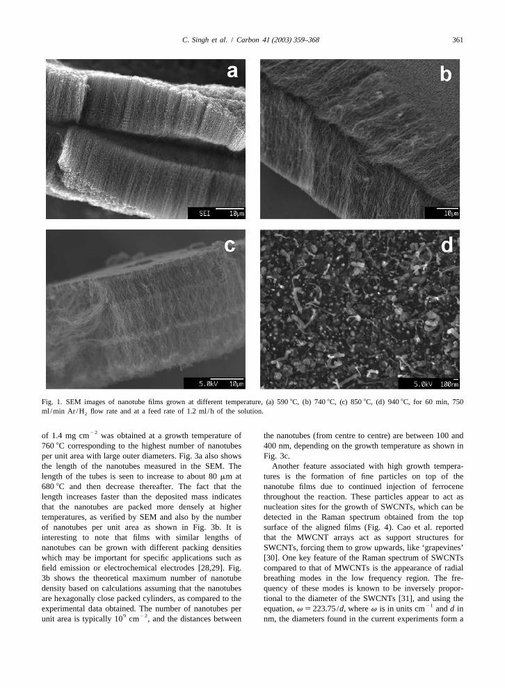
Fig. 1. SEM images of nanotube films grown at different temperature, (a) 5908C, (b) 7408C, (c) 8508C, (d) 9408C, for 60 min, 750ml /min Ar /H flow rate and at a feed rate of 1.2 ml /h of the solution.2
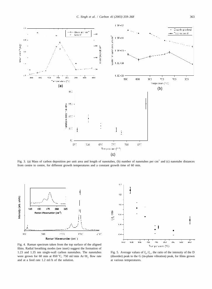
22of 1.4 mg cm was obtained at a growth temperature of the nanotubes (from centre to centre) are between 100 and7608C corresponding to the highest number of nanotubes 400 nm, depending on the growth temperature as shown inper unit area with large outer diameters. Fig. 3a also shows Fig. 3c.the length of the nanotubes measured in the SEM. The Another feature associated with high growth tempera-length of the tubes is seen to increase to about 80mm at tures is the formation of fine particles on top of the6808C and then decrease thereafter. The fact that the nanotube films due to continued injection of ferrocenelength increases faster than the deposited mass indicates throughout the reaction. These particles appear to act asthat the nanotubes are packed more densely at higher nucleation sites for the growth of SWCNTs, which can betemperatures, as verified by SEM and also by the number detected in the Raman spectrum obtained from the topof nanotubes per unit area as shown in Fig. 3b. It is surface of the aligned films (Fig. 4). Cao et al. reportedinteresting to note that films with similar lengths of that the MWCNT arrays act as support structures fornanotubes can be grown with different packing densities SWCNTs, forcing them to grow upwards, like ‘grapevines’which may be important for specific applications such as [30]. One key feature of the Raman spectrum of SWCNTsfield emission or electrochemical electrodes [28,29]. Fig. compared to that of MWCNTs is the appearance of radial3b shows the theoretical maximum number of nanotube breathing modes in the low frequency region. The fre-density based on calculations assuming that the nanotubes quency of these modes is known to be inversely propor-are hexagonally close packed cylinders, as compared to the tional to the diameter of the SWCNTs [31], and using the
21experimental data obtained. The number of nanotubes per equation,v 5 223.75/d, wherev is in units cm andd in9 22unit area is typically 10 cm , and the distances between nm, the diameters found in the current experiments form a

362 C. Singh et al. / Carbon 41 (2003) 359–368
brations of the graphene sheet. Ratios of the D peak to theG peak have been used as an indicator of the amount ofdisorder within carbonaceous materials and nanotubes inparticular [22,33–36]. The smaller theI /I ratio, theD G
fewer defects within the nanotubes. The average values ofthe I /I for the aligned nanotube films as a function ofD G
temperature are given in Fig. 5, and reach a minimum ofabout 0.4 at around 8008C. Thus the growth temperaturerequired to obtain the least defective tubes is similar to thatwhich gives the highest yields (7608C).
3 .2. Effect of ferrocene concentration
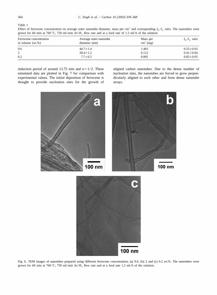
It is believed that the size of the catalyst particlecontrols the diameter of the nanotubes formed [12,37–39].Three different concentrations of ferrocene were examinedand the results are given in Table 1. From SEM, thealignment of the nanotubes was lost when the concen-tration of ferrocene in toluene was below 1 wt.%. TEMmicrographs of the nanotubes are shown in Fig. 6.
Nanotube diameters and total carbon yield decrease withdecreasing ferrocene concentration as a result of theformation of smaller iron clusters. As might be expected,the concentration of encapsulated iron compounds followsthe trend in feedstock concentration. The width of thediameter distribution is reduced by reducing the ferroceneconcentration and hence the rate of iron deposition. At thehighest iron concentrations and temperatures, variations ofnanotube diameters along their length were observed,corresponding to a gradual thickening of the nanotubesduring root growth. These variations were associated withthe presence of encapsulated metal particles or earlyclosure of internal shells, but were not observed in themajority of experiments.
3 .3. Effect of injection duration
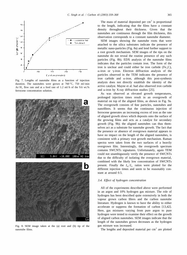
The duration of injection and hence of nanotube growthwas varied between 15 min and 7 h for material grown atFig. 2. The average outer and inner nanotube diameters for7608C and 9.6 wt.% ferrocene concentration in 10%various growth temperatures, and diameter distributions ofH :Ar. The lengths of the aligned nanotubes are plotted innanotubes produced at 590 and 7608C. 2
Fig. 7. The rate of growth is initially linear and is thengradually reduced as the reaction time is increased. The
bimodal distribution with peaks corresponding to 1.23 to decreased growth rate could be attributed to a catalyst1.35 nm. It should be noted that the size observed might deactivation process; however, a more likely explanation isalso be skewed by resonance effects associated with the that these aligned arrays of nanotubes grow by a baseparticular excitation laser used (514 nm) [32]. Even though growth mechanism [12,37,40,41], which becomes limitedthe Raman spectrum indicates the formation of SWCNTs, by the diffusion of the hydrocarbon gas through theit proved difficult to locate any unambiguous images in the increasing thickness of the growing films. The growth rateTEM, and it is possible that the concentration of SWCNTs can be fitted to a square root diffusion law, following the
nis quite low. equation,L(t)5 A(t 2 s) where L(t) is the length of theRaman spectra were collected from a range of locations nanotubes as a function of time,A is a diffusion coeffi-
on the substrate. In carbon-based materials, typically two cient,s is the nucleation time which is passed before themain first order peaks are present, the D peak, observed at system enters the power law growth regime. Solving this
211350 cm relates to the presence of defects whilst the G equation, leads to excellent agreement with the following21 2npeak at 1580 cm is associated with the in-plane vi- parameters: the diffusion term,A58.3mm min , with an
C. Singh et al. / Carbon 41 (2003) 359–368 363
2Fig. 3. (a) Mass of carbon deposition per unit area and length of nanotubes, (b) number of nanotubes per cm and (c) nanotube distancesfrom centre to centre, for different growth temperatures and a constant growth time of 60 min.
Fig. 4. Raman spectrum taken from the top surface of the alignedfilms. Radial breathing modes (see inset) suggest the formation of1.23 and 1.35 nm single-wall carbon nanotubes. The nanotubes Fig. 5. Average values ofI /I , the ratio of the intensity of the DD G
were grown for 60 min at 8508C, 750 ml /min Ar /H flow rate (disorder) peak to the G (in-plane vibration) peak, for films grown2
and at a feed rate 1.2 ml /h of the solution. at various temperatures.
364 C. Singh et al. / Carbon 41 (2003) 359–368
Table 12Effect of ferrocene concentration on average outer nanotube diameter, mass per cm and correspondingI /I ratio. The nanotubes wereD G
grown for 60 min at 7608C, 750 ml /min Ar /H flow rate and at a feed rate of 1.2 ml /h of the solution2
Ferrocene concentration Average outer nanotube Mass per I /I ratioD G2in toluene (wt.%) diameter (nm) cm (mg)
9.6 44.761.4 1.403 0.5560.032 28.461.2 0.112 0.4160.040.2 7.760.2 0.002 0.8260.03
induction period of around 13.75 min andn51/2. These aligned carbon nanotubes. Due to the dense number ofsimulated data are plotted in Fig. 7 for comparison with nucleation sites, the nanotubes are forced to grow perpen-experimental values. The initial deposition of ferrocene is dicularly aligned to each other and form dense nanotubethought to provide nucleation sites for the growth of arrays.
Fig. 6. TEM images of nanotubes prepared using different ferrocene concentration, (a) 9.6, (b) 2 and (c) 0.2 wt.%. The nanotubes weregrown for 60 min at 7608C, 750 ml /min Ar /H flow rate and at a feed rate 1.2 ml /h of the solution.2
C. Singh et al. / Carbon 41 (2003) 359–368 365
2The mass of material deposited per cm is proportionalto the length, indicating that the films have a constantdensity throughout their thickness. Given that thenanotubes are continuous through the film thickness, thisobservation corresponds to a constant nanotube diameter.
SEM images showing the nanotube roots that wereattached to the silica substrates indicate the presence ofmetallic nano-particles (Fig. 8a) and lend further support toa root growth mechanism. SEM images of the tips on thenanotube do not reveal the routine presence of any suchparticles (Fig. 8b). EDX analysis of the nanotube filmsindicates that the particles contain iron. The form of theiron is unclear and could either be iron carbide (Fe C),3
a-iron or g-iron. Electron diffraction analysis of theparticles observed in the TEM indicates the presence ofiron carbide anda-iron, although this post-synthesis
Fig. 7. Lengths of nanotube films as a function of injectionanalysis does not directly establish the identity of theduration. The nanotubes were grown at 7608C, 750 ml /minactive catalyst. Mayne et al. had also observed iron carbideAr/H flow rate and at a feed rate of 1.2 ml /h of the 9.6 wt.%2anda-iron by X-ray diffraction studies [25].ferrocene concentration solution.
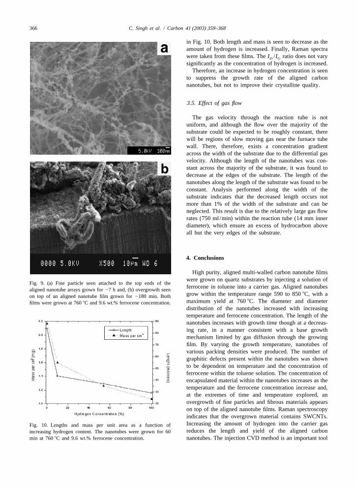
As was observed at elevated growth temperatures,prolonged injection times result in an overgrowth ofmaterial on top of the aligned films, as shown in Fig. 9a.The overgrowth consists of fine particles, nanotubes andnanofibres. It seems that the continuous injection offerrocene generates an increasing excess of iron as the rateof aligned growth slows which deposits onto the surface ofthe growing films and acts as a catalyst for secondarygrowth (Fig. 9b); the aligned nanotubes can thus them-selves act as a substrate for nanotube growth. The fact thatthe presence or absence of overgrown material appears tohave no impact on the length of the aligned nanotubes, isconsistent with a primary root growth mechanism. Ramanspectra were taken from the two surfaces of a heavilyovergrown film. Interestingly, the overgrowth spectrumcontains SWCNTs signatures. Unfortunately, again TEMcould not unambiguously verify the presence of SWCNTsdue to the difficulty of isolating the overgrown material,combined with the likely low concentration of SWCNTspresent. Finally theI /I ratios were plotted for theD G
different injection times and seem to be reasonably con-stant at around 0.5.
3 .4. Effect of hydrogen concentration
All of the experiments described above were performedin an argon and 10% hydrogen gas mixture. The role ofhydrogen has been described quite extensively in both thevapour grown carbon fibres and the carbon nanotubeliterature. Hydrogen is known to have the ability to eitheraccelerate or suppress the formation of carbon [13,42].Here, gas mixtures varying from pure argon to purehydrogen were tested to examine their effect on the growthof aligned carbon nanotubes. SEM images indicate that thelength of the nanotubes grown decreases as the hydrogengas mixture was increased.Fig. 8. SEM image taken at the (a) root and (b) tip of the
2nanotube films. The lengths and deposited material per cm are plotted
366 C. Singh et al. / Carbon 41 (2003) 359–368
in Fig. 10. Both length and mass is seen to decrease as theamount of hydrogen is increased. Finally, Raman spectrawere taken from these films. TheI /I ratio does not varyD G
significantly as the concentration of hydrogen is increased.Therefore, an increase in hydrogen concentration is seen
to suppress the growth rate of the aligned carbonnanotubes, but not to improve their crystalline quality.
3 .5. Effect of gas flow
The gas velocity through the reaction tube is notuniform, and although the flow over the majority of thesubstrate could be expected to be roughly constant, therewill be regions of slow moving gas near the furnace tubewall. There, therefore, exists a concentration gradientacross the width of the substrate due to the differential gasvelocity. Although the length of the nanotubes was con-stant across the majority of the substrate, it was found todecrease at the edges of the substrate. The length of thenanotubes along the length of the substrate was found to beconstant. Analysis performed along the width of thesubstrate indicates that the decreased length occurs notmore than 1% of the width of the substrate and can beneglected. This result is due to the relatively large gas flowrates (750 ml /min) within the reaction tube (14 mm innerdiameter), which ensure an excess of hydrocarbon aboveall but the very edges of the substrate.
4 . Conclusions
High purity, aligned multi-walled carbon nanotube filmswere grown on quartz substrates by injecting a solution of
Fig. 9. (a) Fine particle seen attached to the top ends of theferrocene in toluene into a carrier gas. Aligned nanotubesaligned nanotube arrays grown for|7 h and, (b) overgrowth seengrow within the temperature range 590 to 8508C, with aon top of an aligned nanotube film grown for|180 min. Bothmaximum yield at 7608C. The diameter and diameterfilms were grown at 7608C and 9.6 wt.% ferrocene concentration.distribution of the nanotubes increased with increasingtemperature and ferrocene concentration. The length of thenanotubes increases with growth time though at a decreas-ing rate, in a manner consistent with a base growthmechanism limited by gas diffusion through the growingfilm. By varying the growth temperature, nanotubes ofvarious packing densities were produced. The number ofgraphitic defects present within the nanotubes was shownto be dependent on temperature and the concentration offerrocene within the toluene solution. The concentration ofencapsulated material within the nanotubes increases as thetemperature and the ferrocene concentration increase and,at the extremes of time and temperature explored, anovergrowth of fine particles and fibrous materials appearson top of the aligned nanotube films. Raman spectroscopyindicates that the overgrown material contains SWCNTs.Increasing the amount of hydrogen into the carrier gasFig. 10. Lengths and mass per unit area as a function ofreduces the length and yield of the aligned carbonincreasing hydrogen content. The nanotubes were grown for 60
min at 7608C and 9.6 wt.% ferrocene concentration. nanotubes. The injection CVD method is an important tool
C. Singh et al. / Carbon 41 (2003) 359–368 367
al. Large-scale synthesis of aligned carbon nanotubes. Sci-for the fabrication of controlled nanotube architectures forence 1996;274(5293):1701–3.a range of applications [43].
[17] Terrones M, Grobert N, Olivares J, Zhang JP, Terrones H,Kordatos K et al. Controlled production of aligned-nanotubebundles. Nature 1997;388(6637):52–5.
A cknowledgements [18] Rao CNR, Sen R, Satishkumar BC, Govindaraj A. Largealigned-nanotube bundles from ferrocene pyrolysis. Chem
The author thanks SIRIM Berhad and the Cambridge Commun 1998;(15):1525–6.Commonwealth Trust for financial support. The authors [19] Satishkumar BC, Govindaraj A, Rao CNR. Bundles of
aligned carbon nanotubes obtained by the pyrolysis ofwould also like to acknowledge Kenny Jow, Robert Stearn,ferrocene–hydrocarbon mixtures: role of the metal nanoparti-Marc Hamm, Dr. Francis Tailoka and Dr. Simon Robertscles produced in situ. Chem Phys Lett 1999;307(3–4):158–for their help and discussions.62.
[20] Dai HJ, Kong J, Zhou CW, Franklin N, Tombler T, Cassell Aet al. Controlled chemical routes to nanotube architectures,
R eferences physics, and devices. J Phys Chem B 1999;103(51):11246–55.
[1] Iijima S. Helical microtubules of graphitic carbon. Nature [21] Huang SM, Mau AWH, Turney TW, White PA, Dai LM.1991;354(6348):56–8. Patterned growth of well-aligned carbon nanotubes: a soft-
[2] Ball P. Roll up for the revolution. Nature lithographic approach. J Phys Chem B 2000;104(10):2193–2001;414(6860):142–4. 6.
[3] Ebbesen TW, Ajayan PM. Large-scale synthesis of carbon [22] Kamalakaran R, Terrones M, Seeger T, Kohler-Redlich P,nanotubes. Nature 1992;358(6383):220–2. Ruhle M, Kim YA et al. Synthesis of thick and crystalline
[4] Thess A, Lee R, Nikolaev P, Dai HJ, Petit P, Robert J et al. nanotube arrays by spray pyrolysis. Appl Phys LettCrystalline ropes of metallic carbon nanotubes. Science 2000;77(21):3385–7.1996;273(5274):483–7. [23] Zhang ZJ, Wei BQ, Ramanath G, Ajayan PM. Substrate-site
[5] Joseyacaman M, Mikiyoshida M, Rendon L, Santiesteban selective growth of aligned carbon nanotubes. Appl PhysJG. Catalytic growth of carbon microtubules with fullerene Lett 2000;77(23):3764–6.structure. Appl Phys Lett 1993;62(6):657–9. [24] Cao AY, Ci LJ, Wu GW, Wei BQ, Xu CL, Liang J et al. An
[6] Endo M, Takeuchi K, Kobori K, Takahashi K, Kroto HW, effective way to lower catalyst content in well-alignedSarkar A. Pyrolytic carbon nanotubes from vapor-grown carbon nanotube films. Carbon 2001;39(1):152–5.carbon-fibers. Carbon 1995;33(7):873–81. [25] Mayne M, Grobert N, Terrones M, Kamalakaran R, Ruhle
[7] Ren ZF, Huang ZP, Xu JW, Wang JH, Bush P, Siegal MP et M, Kroto HW et al. Pyrolytic production of aligned carbonal. Synthesis of large arrays of well-aligned carbon nanotubes from homogeneously dispersed benzene-basednanotubes on glass. Science 1998;282(5391):1105–7. aerosols. Chem Phys Lett 2001;338(2–3):101–7.
[8] Treacy MMJ, Ebbesen TW, Gibson JM. Exceptionally high [26] Oberlin A, Endo M, Koyama T. Filamentous growth ofYoung’s modulus observed for individual carbon nanotubes. carbon through benzene decomposition. J Cryst GrowthNature 1996;381(6584):678–80. 1976;32:335–49.
[9] Wong EW, Sheehan PE, Lieber CM. Nanobeam mechanics: [27] Endo M, Takeuchi K, Igarashi S, Kobori K, Shiraishi M,elasticity, strength, and toughness of nanorods and Kroto HW. The production and structure of pyrolytic carbonnanotubes. Science 1997;277(5334):1971–5. nanotubes (PCNTS). J Phys Chem Solids
[10] Frank S, Poncharal P, Wang ZL, de Heer WA. Carbon 1993;54(12):1841–8.nanotube quantum resistors. Science 1998;280(5370):1744– [28] Chhowalla M, Ducati C, Rupesinghe NL, Teo KBK,6. Amaratunga GAJ. Field emission from short and stubby
[11] Andrews R, Jacques D, Rao AM, Derbyshire F, Qian D, Fan vertically aligned carbon nanotubes. Appl Phys LettX et al. Continuous production of aligned carbon nanotubes: 2001;79(13):2079–81.a step closer to commercial realization. Chem Phys Lett [29] Hughes M, Shaffer MSP, Renouf AC, Singh C, Chen GZ,1999;303(5–6):467–74. Fray J et al. Electrochemical capacitance of nanocomposite
[12] Dai HJ, Rinzler AG, Nikolaev P, Thess A, Colbert DT, films formed by coating aligned arrays of carbon nanotubesSmalley RE. Single-wall nanotubes produced by metal-cata- with polypyrrole. Adv Mater 2002;14(5):382–5.lyzed disproportionation of carbon monoxide. Chem Phys [30] Cao AY, Zhang XF, Xu CL, Liang J, Wu DH, Chen XH et al.Lett 1996;260(3–4):471–5. Grapevine-like growth of single walled carbon nanotubes
[13] Endo M. Grow carbon-fibers in the vapor-phase. Chemtech among vertically aligned multiwalled nanotube arrays. Appl1988;18(9):568–76. Phys Lett 2001;79(9):1252–4.
[14] Kato T, Kusakabe K, Morooka S. Process of formation of [31] Bandow S, Asaka S, Saito Y, Rao AM, Grigorian L, Richtervapor-grown carbon-fibers by gas-phase reaction using ul- E et al. Effect of the growth temperature on the diametertrafine iron catalyst particles. J Mater Sci Lett distribution and chirality of single-wall carbon nanotubes.1992;11(10):674–7. Phys Rev Lett 1998;80(17):3779–82.
[15] Tennent HG, Barber JJ, Hoch R. Carbon fibrils, method for [32] Rao AM, Richter E, Bandow S, Chase B, Eklund PC,producing same and adhesive compositions containing same. Williams KA et al. Diameter-selective Raman scatteringUS patent 5578543, 1996. from vibrational modes in carbon nanotubes. Science
[16] Li WZ, Xie SS, Qian LX, Chang BH, Zou BS, Zhou WY et 1997;275(5297):187–91.
368 C. Singh et al. / Carbon 41 (2003) 359–368
[33] Tunistra F, Koenig JL. Raman spectrum of graphite. J Chem persed Fe–Mo nanoparticles as the catalyst for CVD syn-Phys 1970;53(3):1126–30. thesis of carbon nanotubes. Chem Mater 2001;13(3):1008–
[34] Tan PH, Zhang SL, Yue KT, Huang FM, Shi ZJ, Zhou XH et 14.al. Comparative Raman study of carbon nanotubes prepared [39] Cheung CL, Kurtz A, Park H, Lieber CM. Diameter-con-by dc arc discharge and catalytic methods. J Raman Spec- trolled synthesis of carbon nanotubes. J Phys Chem Btrosc 1997;28(5):369–72. 2002;106(10):2429–33.
[35] Endo M, Nishimura K, Kim YA, Hakamada K, Matushita T, [40] Kong J, Soh HT, Cassell AM, Quate CF, Dai HJ. SynthesisDresselhaus MS et al. Raman spectroscopic characterization of individual single-walled carbon nanotubes on patternedof submicron vapor-grown carbon fibers and carbon nanofib- silicon wafers. Nature 1998;395(6705):878–81.ers obtained by pyrolyzing hydrocarbons. J Mater Res [41] Kong J, Cassell AM, Dai HJ. Chemical vapor deposition of1999;14(12):4474–7. methane for single-walled carbon nanotubes. Chem Phys
[36] Endo M, Kim YA, Fukai Y, Hayashi T, Terrones M, Terrones Lett 1998;292(4–6):567–74.H et al. Comparison study of semi-crystalline and highly [42] Ci LJ, Wei JQ, Wei BQ, Liang J, Xu CL, Wu DH. Carboncrystalline multiwalled carbon nanotubes. Appl Phys Lett nanofibers and single-walled carbon nanotubes prepared by2001;79(10):1531–3. the floating catalyst method. Carbon 2001;39(3):329–35.
[37] Li YM, Kim W, Zhang YG, Rolandi M, Wang DW, Dai HJ. [43] Wei BQ, Vajtai R, Jung Y, Ward J, Zhang R, Ramanath G etGrowth of single-walled carbon nanotubes from discrete al. Organized assembly of carbon nanotubes—cunning re-catalytic nanoparticles of various sizes. J Phys Chem B finements help to customize the architecture of nanotube2001;105(46):11424–31. structures. Nature 2002;416(6880):495–6.
[38] Li Y, Liu J, Wang YQ, Wang ZL. Preparation of monodis-