PRODUCT: TJ Corner Guards READ INSTRUCTIONS IN FULL …
15
PRODUCT: TJ Corner Guards The MetalCloak experience includes the ease of installation of our products. We design for most contingencies, but installation may be different based on different Jeep condition, configuration and/or year. We are continually trying to improve our products and instructions – please help us by providing feedback and pictures if you find any part of the instructions that do not match your particular Jeep or are not easily understandable. If you have any difficulties at all, please give us a call. Thank you and enjoy your MetalCloak Products! IMPORTANT NOTE: We use Stainless Steel Hardware where possible. Therefore, a tube of Silver Anti-seize is provided and should be used on all bolts—only a small amount is needed. WARRANTY INFORMATION: This article is sold without warranty expressed or implied. No warranty or representation is made as to this products ability to protect the user from injury or death. The user assumes that risk. The effectiveness, warranty and longevity of this equipment are directly related to the manner in which it is INSTALLED, USED and/or MAINTAINED. THE USER ASSUMES ALL RISK. By purchasing this product and opening the packaging, purchasers expressly acknowledge, understand and agree that they take, select and purchase these MetalCloak products from Armored Works, LLC, its affiliates and distributors and agents as is and with all faults. The entire risk as to the quality and performance of these MetalCloak products is with the purchaser. Working on your vehicle can be a dangerous activity. If you are unsure of what you are doing, please leave mechanical or safety critical work to a skilled mechanic. We take no responsibility for the incorrect use and/or installation of MetalCloak products. READ INSTRUCTIONS IN FULL BEFORE INSTALLATION. QUESTIONS? CALL 916-631-8071 M-F 7:00 AM – 5:00 PM PST REV: E | 07-01-2015| II-2432
Transcript of PRODUCT: TJ Corner Guards READ INSTRUCTIONS IN FULL …

PRODUCT: TJ Corner Guards
The MetalCloak experience includes the ease of installation of our products. We design for most contingencies, but installation may be different based on different Jeep condition, configuration and/or year.
We are continually trying to improve our products and instructions – please help us by providing feedback and pictures if you find any part of the instructions that do not match your particular Jeep or are not easily understandable.
If you have any difficulties at all, please give us a call. Thank you and enjoy your MetalCloak Products!
IMPORTANT NOTE: We use Stainless Steel Hardware where possible. Therefore, a tube of Silver Anti-seize is provided and should be used on all bolts—only a small amount is needed.
WARRANTY INFORMATION: This article is sold without warranty expressed or implied. No warranty or representation is made as to this products ability to protect the user from injury or death. The user assumes that risk. The effectiveness, warranty and longevity of this equipment are directly related to the manner in which it is INSTALLED, USED and/or MAINTAINED. THE USER ASSUMES ALL RISK. By purchasing this product and opening the packaging, purchasers expressly acknowledge, understand and agree that they take, select and purchase these MetalCloak products from Armored Works, LLC, its affiliates and distributors and agents as is and with all faults. The entire risk as to the quality and performance of these MetalCloak products is with the purchaser. Working on your vehicle can be a dangerous activity. If you are unsure of what you are doing, please leave mechanical or safety critical work to a skilled mechanic. We take no responsibility for the incorrect use and/or installation of MetalCloak products.
READ INSTRUCTIONS IN FULL BEFORE INSTALLATION. QUESTIONS? CALL 916-631-8071 M-F 7:00 AM – 5:00 PM PST
REV: E | 07-01-2015| II-2432
II-2432 | Rev E | 07/01/2015 | Copyright 2011 Armored Works, LLC
Section 1: Tools & Notes on Installation
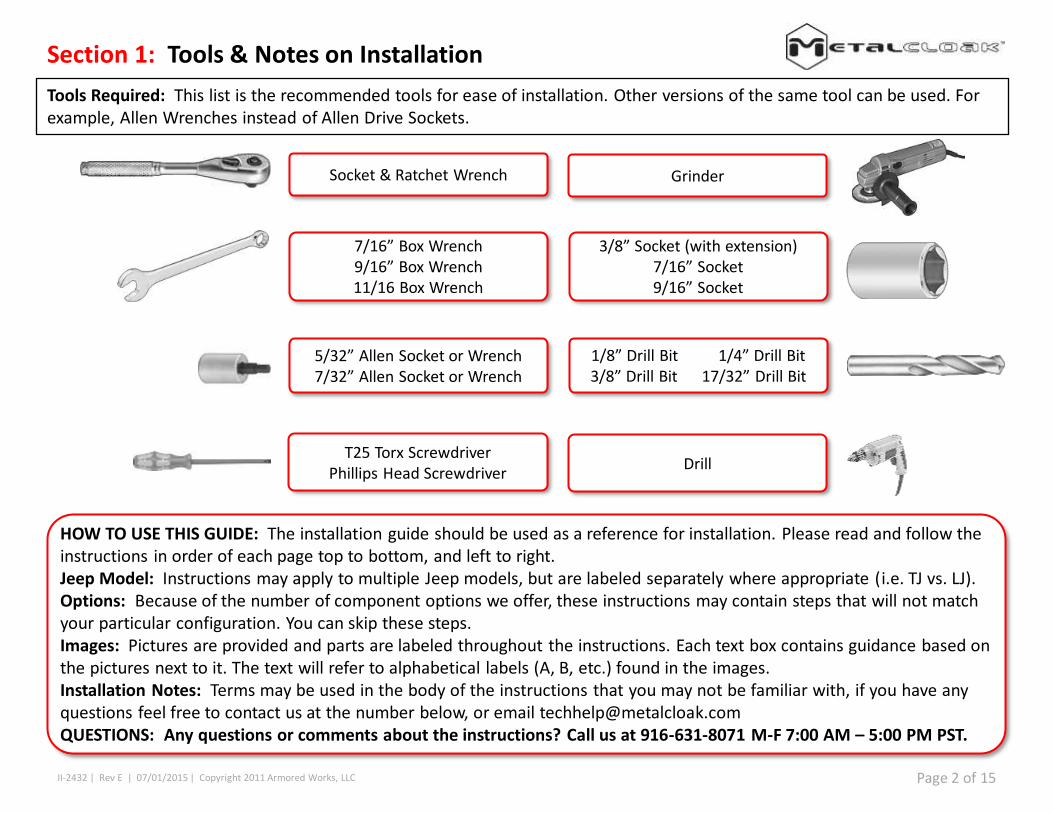
Tools Required: This list is the recommended tools for ease of installation. Other versions of the same tool can be used. For example, Allen Wrenches instead of Allen Drive Sockets.
HOW TO USE THIS GUIDE: The installation guide should be used as a reference for installation. Please read and follow the instructions in order of each page top to bottom, and left to right.Jeep Model: Instructions may apply to multiple Jeep models, but are labeled separately where appropriate (i.e. TJ vs. LJ).Options: Because of the number of component options we offer, these instructions may contain steps that will not match your particular configuration. You can skip these steps.Images: Pictures are provided and parts are labeled throughout the instructions. Each text box contains guidance based on the pictures next to it. The text will refer to alphabetical labels (A, B, etc.) found in the images.Installation Notes: Terms may be used in the body of the instructions that you may not be familiar with, if you have any questions feel free to contact us at the number below, or email [email protected]: Any questions or comments about the instructions? Call us at 916-631-8071 M-F 7:00 AM – 5:00 PM PST.
Socket & Ratchet Wrench Grinder
T25 Torx ScrewdriverPhillips Head Screwdriver
Drill
1/8” Drill Bit 1/4” Drill Bit3/8” Drill Bit 17/32” Drill Bit
5/32” Allen Socket or Wrench7/32” Allen Socket or Wrench
3/8” Socket (with extension)7/16” Socket9/16” Socket
7/16” Box Wrench9/16” Box Wrench11/16 Box Wrench
Page 2 of 15

II-2432 | Rev E | 07/01/2015 | Copyright 2011 Armored Works, LLC
Section 2: Product Components
Page 3 of 15
II-2432 | Rev E | 07/01/2015 | Copyright 2011 Armored Works, LLC
Section 3: Installation Instructions
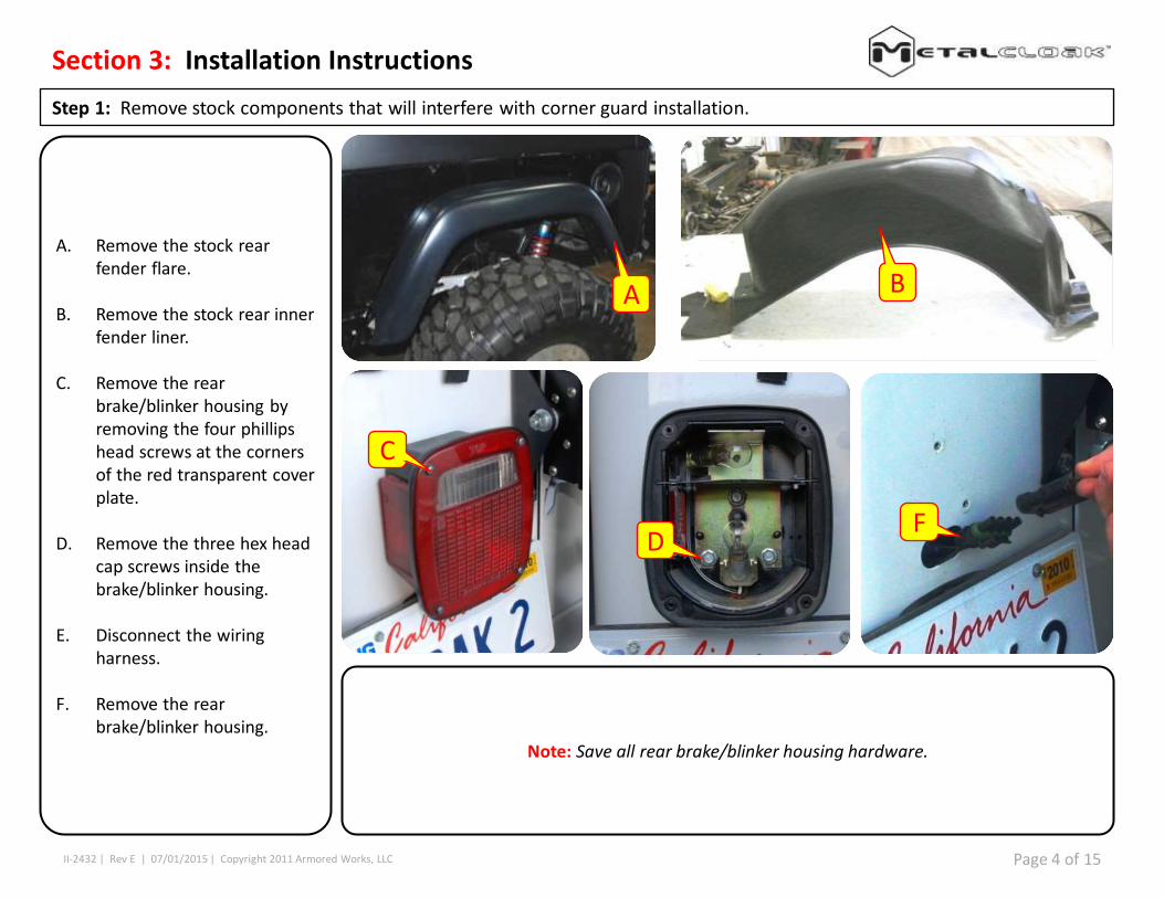
Step 1: Remove stock components that will interfere with corner guard installation.
A. Remove the stock rear fender flare.
B. Remove the stock rear inner fender liner.
C. Remove the rear brake/blinker housing by removing the four phillipshead screws at the corners of the red transparent cover plate.
D. Remove the three hex head cap screws inside the brake/blinker housing.
E. Disconnect the wiring harness.
F. Remove the rear brake/blinker housing.
Note: Save all rear brake/blinker housing hardware.
A B
C
DF
Page 4 of 15

II-2432 | Rev E | 07/01/2015 | Copyright 2011 Armored Works, LLC
Section 3: Installation Instructions
Step 1: Remove stock components that will interfere with corner guard installation.
G. Using a T25 torx driver remove the four outer retainer screws on the gas tank fill spout plastic retainer.
H. Remove the four inner retainer screws using a T25 torx driver.
I. Remove the gas tank fill spout plastic retainer.
Note: Save all of the gas tank fill spout plastic retainer hardware.
G
H
I
Page 5 of 15

II-2432 | Rev E | 07/01/2015 | Copyright 2011 Armored Works, LLC
Section 3: Installation Instructions
Step 1: Remove stock components that will interfere with corner guard installation.
J. Remove rear license plate.
K. Remove the four hex screws on the rear license plate holder.
L. Remove the rear license plate holder.
Note: Save all of the gas tank fill spout plastic retainer hardware.
J KL
Page 6 of 15

II-2432 | Rev E | 07/01/2015 | Copyright 2011 Armored Works, LLC
Section 3: Installation Instructions
Step 2: Fix Corner Guard Into Position in Order to Drill Holes for Holding Fasteners.
M. Remove /clean all dirt, stock rivet nuts or protrusions from the side of the Jeep. Fix any body damage in order to assure the corner guards can be mounted flush to the Jeep body side, corner and rear.
M
Page 7 of 15

II-2432 | Rev E | 07/01/2015 | Copyright 2011 Armored Works, LLC
Section 3: Installation Instructions
Step 2: Fix Corner Guard Into Position in Order to Drill Holes for Holding Fasteners.
Note: Images show a raw metal Corner Guard. Special care must be taken with Powder Coated Corner Guards to protect coating during the installation process. Corner Guard can be installed with Jeep Top installed,however installation is easier if Jeep Top is removed.
N. Using C-Clamps or Vice Grips fix the corner guards into place. If your corner guards are powder coated, use rags to protect the coating from the clamps. The corner guards should fit tightly to the Jeep body corner with minimal gap.
Clamp Locations:
O. Top of the 3” radius bend.
P. Bottom of the 3” radius bend
Q. Lower front edge of the corner guard
R. Top of the wheel well of the corner guard.
S. Inside of gas intake spout.
N
R
O
PQ
S
N
Page 8 of 15

II-2432 | Rev E | 07/01/2015 | Copyright 2011 Armored Works, LLC
Section 3: Installation Instructions
Step 2: Fix Corner Guard Into Position in Order to Drill Holes for Holding Fasteners.
T. Inspect points to insure that the alignment is proper.
Inspection Points:
U. Gas intake spout mounting holes.
V. Rear brake/marker housing mount holes
W. Lower edge of the corner guard and jeep body should be flush.
X. 10 to 2 o’clock of wheel well of corner guard and jeep body.
Note: If you already have a MetalCloak Rocker Rail installed, check alignment of two bolt holes. This is just a check as the Rocker Rail can float forward or backwards on Jeep and should normally be installed after the Corner Guard. The Corner Guard has a fixed position.
UV
W
X
T
Note
Page 9 of 15

II-2432 | Rev E | 07/01/2015 | Copyright 2011 Armored Works, LLC
Section 3: Installation Instructions
Step 3: Drill All Holes in Jeep Required for Installation.
Y. Center Punch and pilot drill (1/8” drill bit all holes marked as followed:
Z. Drill the following holes to the designated finish size without removing corner guards.
3/8” drill size
AA. Release all C-Clamps and Vise Grips and Remove Corner Guard from Jeep. Corner Guard will not be needed again until final installation. This is a good time to complete coating/painting of raw metal Corner Guards. After removal of Corner Guard, drill the following holes to finish size.
1/2” Drill Size – Provides clearance hole in Jeep body for Rear Flare retaining bolts.17/32” Drill Size – Provides hole size for installation of 3/8”-16 Rivet Nut in next step.
Z
Y
AA
Driver’s Side Corner Guard Passenger’s Side Corner Guard
Page 10 of 15

Passenger’s Side Corner Guard
II-2432 | Rev E | 07/01/2015 | Copyright 2011 Armored Works, LLC
Section 3: Installation Instructions
Step 4: Install Corner Guards.
BB. Fix the corner guards in position as shown on page 7. Install the following fasteners at the designated locations:
3/8” – 16 x 1” SBHC Screw, 3/8” washer, and 3/16” – 16 Nylock Nut3/8” – 16 x 1” SBHC Screw
Note: Images show a raw metal Corner Guard. Special care must be taken with Powder Coated Corner Guards to protect coating during the installation process. Corner Guard can be installed with Jeep Top installed, however installation is easier if Jeep Top is removed.
Driver’s Side Corner Guard
CC. Install flare retaining fasteners in the locations.
DD. 3/8”-16 x 1 ¼” SBHC ScrewsEE. 3/8” washersFF. Backing Plates
Note: If a MetalCloak Rear Flare is to be installed leave these fasteners loose but in place. If a MetalCloak Rear Flare is NOT to be installed fully tighten fasteners.
DD FF
EE
Note
Page 11 of 15

II-2432 | Rev E | 07/01/2015 | Copyright 2011 Armored Works, LLC
Section 3: Installation Instructions
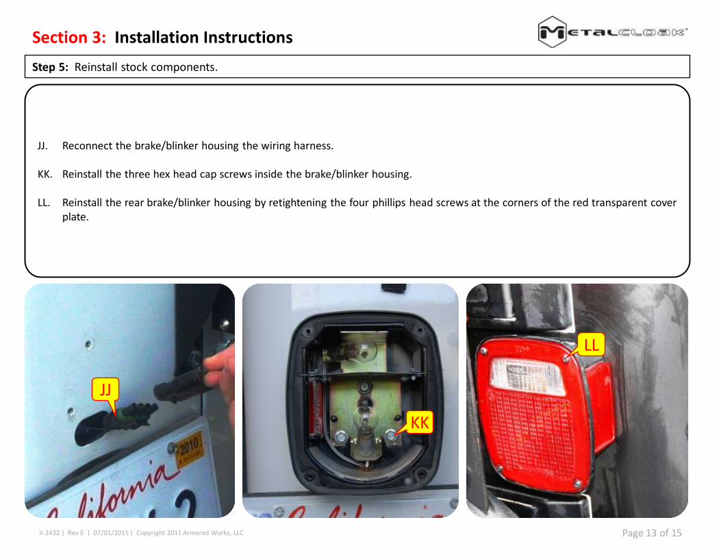
Step 5: Reinstall stock components.
GG. Re-install the gas tank fill spout plastic retainer.
HH. Re-install the four inner retainer screws using a T25 torx driver.
II. Using a T25 torx driver re-install the four outer retainer screws on the gas tank fill spout plastic retainer.
GG
HH
II
Page 12 of 15
II-2432 | Rev E | 07/01/2015 | Copyright 2011 Armored Works, LLC
Section 3: Installation Instructions
Step 5: Reinstall stock components.
JJ. Reconnect the brake/blinker housing the wiring harness.
KK. Reinstall the three hex head cap screws inside the brake/blinker housing.
LL. Reinstall the rear brake/blinker housing by retightening the four phillips head screws at the corners of the red transparent cover plate.
FLL
KK
JJ
Page 13 of 15

II-2432 | Rev E | 07/01/2015 | Copyright 2011 Armored Works, LLC
Section 3: Installation Instructions
Step 5: Reinstall stock components.
MM.Reinstall the rear license plate holder.
NN. Reinstall the four hex screws on the rear license plate holder.
OO. Reinstall rear license plate.
MMNN
OO
Page 14 of 15

II-2432 | Rev E | 07/01/2015 | Copyright 2011 Armored Works, LLC Page 15 of 15
Phase 3: Installation
Step 6: Mount Rear Fender Flares (If applicable)
PP. Align the flare housing with the 3/8” Button Head Screws so that the screw head and washers are both on the OUTSIDE of the bracket.
QQ. Front and Rear Balls will snap into place on the mounting boss. Finger tighten the 3/8” Countersunk Screws through the balls.
RR. Tighten the 3/8” Button Head Screws against the bracket [PP].
SS. Tighten the 3/8” Countersunk Screws in each ball [QQ].
PP
Note: The MetalCloak Rear Flares are easily removable to provide you with the maximum clearance during your off-road experience. Simply follow step 5 in reverse to safely remove your flares in minutes.