Product Technical Specification AirPrime XM1100 Sheets/Sierra Wireless PDFs...AirPrime XM1100...
33
Product Technical Specification AirPrime XM1100 41111067 Rev 1
Transcript of Product Technical Specification AirPrime XM1100 Sheets/Sierra Wireless PDFs...AirPrime XM1100...

Product Technical Specification
AirPrime XM1100
41111067Rev 1
AirPrime XM1100 Product Technical Specification
Important Notice
Due to the nature of wireless communications, transmission and reception of data can never be guaranteed. Data may be delayed, corrupted (i.e., have errors) or be totally lost. Although significant delays or losses of data are rare when wireless devices such as the Sierra Wireless modem are used in a normal manner with a well-constructed network, the Sierra Wireless modem should not be used in situations where failure to transmit or receive data could result in damage of any kind to the user or any other party, including but not limited to personal injury, death, or loss of property. Sierra Wireless accepts no responsibility for damages of any kind resulting from delays or errors in data transmitted or received using the Sierra Wireless modem, or for failure of the Sierra Wireless modem to transmit or receive such data.
Safety and Hazards
Do not operate the Sierra Wireless modem in areas where blasting is in progress, where explosive atmospheres may be present, near medical equipment, near life support equipment, or any equipment which may be susceptible to any form of radio interference. In such areas, the Sierra Wireless modem MUST BE POWERED OFF. The Sierra Wireless modem can transmit signals that could interfere with this equipment.
Do not operate the Sierra Wireless modem in any aircraft, whether the aircraft is on the ground or in flight. In aircraft, the Sierra Wireless modem MUST BE POWERED OFF. When operating, the Sierra Wireless modem can transmit signals that could interfere with various onboard systems.
Note: Some airlines may permit the use of cellular phones while the aircraft is on the ground and the door is open. Sierra Wireless modems may be used at this time.
The driver or operator of any vehicle should not operate the Sierra Wireless modem while in control of a vehicle. Doing so will detract from the driver or operator's control and operation of that vehicle. In some states and provinces, operating such communications devices while in control of a vehicle is an offence.
Limitation of Liability
The information in this manual is subject to change without notice and does not represent a commitment on the part of Sierra Wireless. SIERRA WIRELESS AND ITS AFFILIATES SPECIFICALLY DISCLAIM LIABILITY FOR ANY AND ALL DIRECT, INDIRECT, SPECIAL, GENERAL, INCIDENTAL, CONSEQUENTIAL, PUNITIVE OR EXEMPLARY DAMAGES INCLUDING, BUT NOT LIMITED TO, LOSS OF PROFITS OR REVENUE OR ANTICIPATED PROFITS OR REVENUE ARISING OUT OF THE USE OR INABILITY TO USE ANY SIERRA WIRELESS PRODUCT, EVEN IF SIERRA WIRELESS AND/OR ITS AFFILIATES HAS BEEN ADVISED OF THE POSSIBILITY OF SUCH DAMAGES OR THEY ARE FORESEEABLE OR FOR CLAIMS BY ANY THIRD PARTY.
Notwithstanding the foregoing, in no event shall Sierra Wireless and/or its affiliates aggregate liability arising under or in connection with the Sierra Wireless product, regardless of the number of events, occurrences, or claims giving rise to liability, be in excess of the price paid by the purchaser for the Sierra Wireless product.
Rev 1 Jun.17 2 41111067
Preface
Patents This product may contain technology developed by or for Sierra Wireless Inc. This product includes technology licensed from QUALCOMM®. This product is manufactured or sold by Sierra Wireless Inc. or its affiliates under one or more patents licensed from InterDigital Group and MMP Portfolio Licensing.
Copyright © 2017 Sierra Wireless. All rights reserved.
Trademarks Sierra Wireless®, AirPrime®, AirLink®, AirVantage® and the Sierra Wireless logo are registered trademarks of Sierra Wireless.
Windows® and Windows Vista® are registered trademarks of Microsoft Corporation.
Macintosh® and Mac OS X® are registered trademarks of Apple Inc., registered in the U.S. and other countries.
QUALCOMM® is a registered trademark of QUALCOMM Incorporated. Used under license.
Other trademarks are the property of their respective owners.
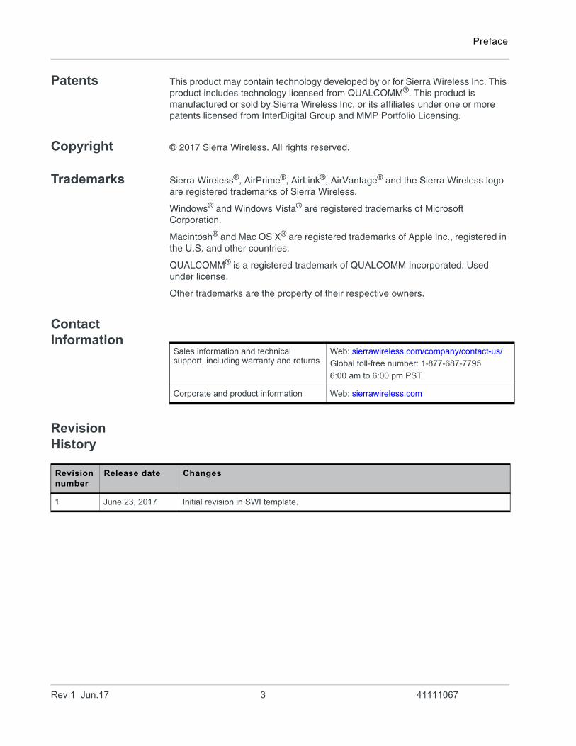
Contact Information
Revision History
Sales information and technical support, including warranty and returns
Web: sierrawireless.com/company/contact-us/
Global toll-free number: 1-877-687-7795
6:00 am to 6:00 pm PST
Corporate and product information Web: sierrawireless.com
Revision number
Release date Changes
1 June 23, 2017 Initial revision in SWI template.
Rev 1 Jun.17 3 41111067
Contents
Function Description . . . . . . . . . . . . . . . . . . . . . . . . . . . . . . . . . . . . . . . . . . . . .6
Overview. . . . . . . . . . . . . . . . . . . . . . . . . . . . . . . . . . . . . . . . . . . . . . . . . . . . . 6
Potential Applications . . . . . . . . . . . . . . . . . . . . . . . . . . . . . . . . . . . . . . . . .6
Product Highlights and Features . . . . . . . . . . . . . . . . . . . . . . . . . . . . . . . . . . 7
System Block Diagram . . . . . . . . . . . . . . . . . . . . . . . . . . . . . . . . . . . . . . . . . . 8
Multi-tone Active Interference Canceller. . . . . . . . . . . . . . . . . . . . . . . . . . . . . 8
1PPS . . . . . . . . . . . . . . . . . . . . . . . . . . . . . . . . . . . . . . . . . . . . . . . . . . . . . . . 8
AGPS for faster TTFF (HOST) . . . . . . . . . . . . . . . . . . . . . . . . . . . . . . . . . . . . 8
EASY™ . . . . . . . . . . . . . . . . . . . . . . . . . . . . . . . . . . . . . . . . . . . . . . . . . . . . . 9
PPS sync NMEA. . . . . . . . . . . . . . . . . . . . . . . . . . . . . . . . . . . . . . . . . . . . . . . 9
Specifications . . . . . . . . . . . . . . . . . . . . . . . . . . . . . . . . . . . . . . . . . . . . . . . . . .11
Mechanical Dimensions . . . . . . . . . . . . . . . . . . . . . . . . . . . . . . . . . . . . . . . . 11
Recommended PCB Pad Layout . . . . . . . . . . . . . . . . . . . . . . . . . . . . . . . . . 11
Pin Configuration . . . . . . . . . . . . . . . . . . . . . . . . . . . . . . . . . . . . . . . . . . . . . 12
Pin Assignment. . . . . . . . . . . . . . . . . . . . . . . . . . . . . . . . . . . . . . . . . . . . . . . 12
Description of I/O Pins . . . . . . . . . . . . . . . . . . . . . . . . . . . . . . . . . . . . . . . . . 13
Specifications . . . . . . . . . . . . . . . . . . . . . . . . . . . . . . . . . . . . . . . . . . . . . . . . 15
Absolute Maximum Ratings . . . . . . . . . . . . . . . . . . . . . . . . . . . . . . . . . . . . . 16
Operating Conditions . . . . . . . . . . . . . . . . . . . . . . . . . . . . . . . . . . . . . . . . . . 16
Protocols . . . . . . . . . . . . . . . . . . . . . . . . . . . . . . . . . . . . . . . . . . . . . . . . . . . . . .17
NMEA Output Sentences . . . . . . . . . . . . . . . . . . . . . . . . . . . . . . . . . . . . . . . 17
GGA—Time, Position and Related data of Navigation Fix . . . . . . . . . . . . . . 17
GSA—GPS DOP and Active Satellites. . . . . . . . . . . . . . . . . . . . . . . . . . . . . 19
GSV— Satellites in View . . . . . . . . . . . . . . . . . . . . . . . . . . . . . . . . . . . . . . . 19
RMC—Recommended Minimum Navigation Information. . . . . . . . . . . . . . . 20
VTG—Course and Speed information Relating to the Ground. . . . . . . . . . . 21
MTK NMEA Command Protocols . . . . . . . . . . . . . . . . . . . . . . . . . . . . . . . . . 22
Rev 1 Jun.17 4 41111067
Contents
Reference Design . . . . . . . . . . . . . . . . . . . . . . . . . . . . . . . . . . . . . . . . . . . . . . . 23
Reference Schematic Design for Using the Active Antenna . . . . . . . . . . . . 23
Schematic Reference Design for Using the Patch Antenna . . . . . . . . . . 24
Packing and Handling . . . . . . . . . . . . . . . . . . . . . . . . . . . . . . . . . . . . . . . . . . . 25
Packaging and Handling (Tape Reel) . . . . . . . . . . . . . . . . . . . . . . . . . . . . . 25
Storage and Floor Life Guidelines . . . . . . . . . . . . . . . . . . . . . . . . . . . . . . . . 26
Moisture Color Coded Card & Caution Label . . . . . . . . . . . . . . . . . . . . . 26
Conditions for Pre-baking . . . . . . . . . . . . . . . . . . . . . . . . . . . . . . . . . . . . . . 27
Drying. . . . . . . . . . . . . . . . . . . . . . . . . . . . . . . . . . . . . . . . . . . . . . . . . . . . . . 28
ESD Handling . . . . . . . . . . . . . . . . . . . . . . . . . . . . . . . . . . . . . . . . . . . . . . . 29
Reflow Soldering Temperature Profile . . . . . . . . . . . . . . . . . . . . . . . . . . . . . . 30
SMT Reflow Soldering Temperature Profile (For Reference Only) . . . . . . . 30
Manual Soldering. . . . . . . . . . . . . . . . . . . . . . . . . . . . . . . . . . . . . . . . . . . . . 33
Rev 1 Jun.17 5 41111067
1
1: Function DescriptionOverview
The XM1100 is a GPS receiver; it is one of the smallest MediaTek-based modules in the world, for it has an ultra-compact size of 9.0 x 9.5 x 2.1 mm in a QFN Package. This ultra-compact module provides unique design of SMPS is capable of reducing power consumption to a great extent.
The XM1100 is built based on MediaTek’s new generation GPS Chipset MT3337(E). It supports up to 210 PRN channels with 66 search channels and 22 simultaneous tracking channels. With support of QZSS and AGPS, The XM1100 can provide even more accurate positioning. Its Tone Active Interference Canceller is capable of removing 12 active noise sources and such feature enables more flexibility in system design.
The XM1100 is integrated along with power managements and many advanced features, including EASY™, EPO™, PPS sync NMEA and logger. It is ideally suitable for power-sensitive devices especially for portable applications.
Potential Applications
• Handheld Devices • M2M applications• Asset management• Surveillance systems• Wearable products
Figure 1-1: XM1110
Rev 1 Jun.17 641111067
Function Description
Product Highlights and Features
• 22 tracking/ 66 acquisition-channel GPS receiver• Supports QZSS• Sensitivity: -165dBm• Update Rate: up to 10Hz • 12 multi-tone active interference canceller • High accuracy 1-PPS timing (±20ns RMS) and the pulse width is 100ms • AGPS Support for Fast TTFF (Host Aiding EPO™)1
• EASY™: Self-Generated Orbit Prediction for instant positioning fix2
• PPS sync NMEA2
• Consumption current(@3.3V):• Acquisition: 19mA/ 20mA / 21mA (min / typical / max)• Tracking: 18mA / 19mA / 24mA (min / typical / max)• RoHS compliant
1. Please refer to “GTop Host Aiding EPO Application Note”.2. The features need customized firmware or command programming handled by
the customer. Please refer to our “PMTK Command List”.
Rev 1 Jun.17 7 41111067
AirPrime XM1100 Product Technical Specification
System Block Diagram
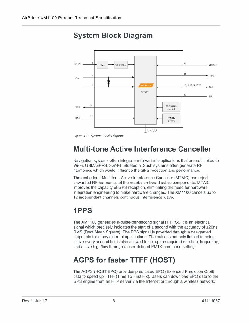
Figure 1-2: System Block Diagram
Multi-tone Active Interference Canceller
Navigation systems often integrate with variant applications that are not limited to Wi-Fi, GSM/GPRS, 3G/4G, Bluetooth. Such systems often generate RF harmonics which would influence the GPS reception and performance.
The embedded Multi-tone Active Interference Canceller (MTAIC) can reject unwanted RF harmonics of the nearby on-board active components. MTAIC improves the capacity of GPS reception, eliminating the need for hardware integration engineering to make hardware changes. The XM1100 cancels up to 12 independent channels continuous interference wave.
1PPS
The XM1100 generates a-pulse-per-second signal (1 PPS). It is an electrical signal which precisely indicates the start of a second with the accuracy of ±20ns RMS (Root Mean Square). The PPS signal is provided through a designated output pin for many external applications. The pulse is not only limited to being active every second but is also allowed to set up the required duration, frequency, and active high/low through a user-defined PMTK command setting.
AGPS for faster TTFF (HOST)
The AGPS (HOST EPO) provides predicated EPO (Extended Prediction Orbit) data to speed up TTFF (Time To First Fix). Users can download EPO data to the GPS engine from an FTP server via the Internet or through a wireless network.
Rev 1 Jun.17 8 41111067
Function Description
The GPS engine of the module will adopt EPO data to assist with position calculation when navigation information from satellites is insufficient due to a weak signal. For more details on EPO, please visit our website.
EASY™
EASY™ (Embedded Assist System) is for quick positioning when information received from the satellites is insufficient. With EASY™ technology, the GPS engine is able to calculate and predict a single ephemeris automatically up to three days when the power is on. It then saves the predicted information into memory so the GPS engine can use this information for positioning later if information received from the satellites is insufficient. This function is useful for TTFF improvement to allow positioning even under weak signal conditions (e.g. in dense urban areas). Backup power (VBACKUP) is required for this feature.
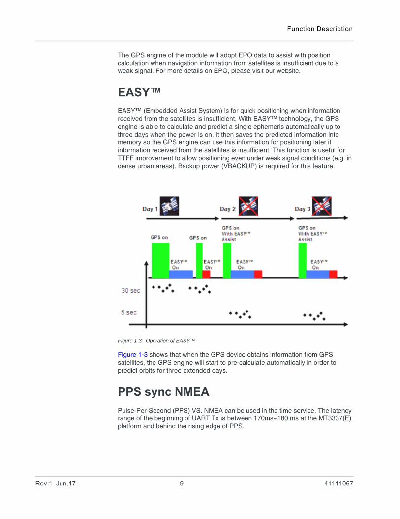
Figure 1-3: Operation of EASY™
Figure 1-3 shows that when the GPS device obtains information from GPS satellites, the GPS engine will start to pre-calculate automatically in order to predict orbits for three extended days.
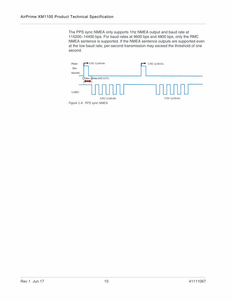
PPS sync NMEA
Pulse-Per-Second (PPS) VS. NMEA can be used in the time service. The latency range of the beginning of UART Tx is between 170ms~180 ms at the MT3337(E) platform and behind the rising edge of PPS.
Rev 1 Jun.17 9 41111067
AirPrime XM1100 Product Technical Specification
The PPS sync NMEA only supports 1Hz NMEA output and baud rate at 115200~14400 bps. For baud rates at 9600 bps and 4800 bps, only the RMC NMEA sentence is supported. If the NMEA sentence outputs are supported even at the low baud rate, per-second transmission may exceed the threshold of one second.
Figure 1-4: PPS sync NMEA
Rev 1 Jun.17 10 41111067
2
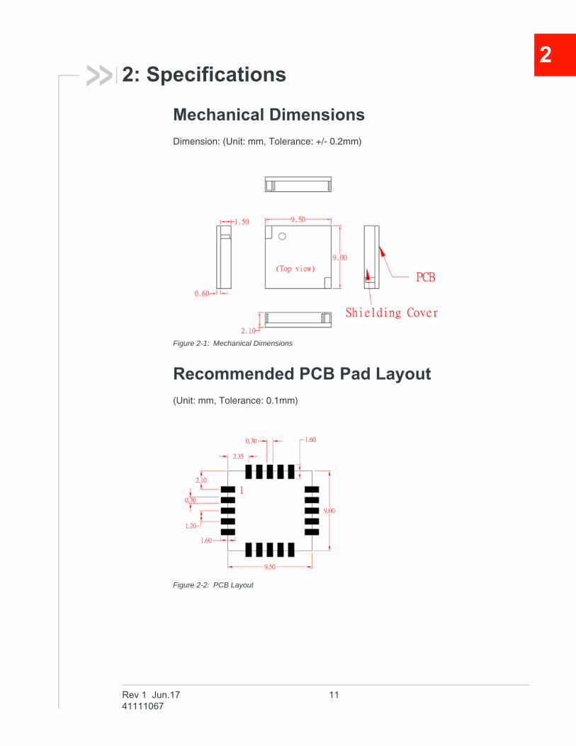
2: SpecificationsMechanical Dimensions
Dimension: (Unit: mm, Tolerance: +/- 0.2mm)
Figure 2-1: Mechanical Dimensions
Recommended PCB Pad Layout
(Unit: mm, Tolerance: 0.1mm)
Figure 2-2: PCB Layout
Rev 1 Jun.17 1141111067
AirPrime XM1100 Product Technical Specification
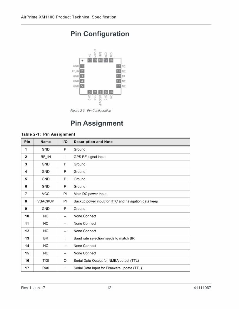
Pin Configuration
Figure 2-3: Pin Configuration
Pin Assignment
Table 2-1: Pin Assignment
Pin Name I/O Description and Note
1 GND P Ground
2 RF_IN I GPS RF signal input
3 GND P Ground
4 GND P Ground
5 GND P Ground
6 GND P Ground
7 VCC PI Main DC power input
8 VBACKUP PI Backup power input for RTC and navigation data keep
9 GND P Ground
10 NC -- None Connect
11 NC -- None Connect
12 NC -- None Connect
13 BR I Baud rate selection needs to match BR
14 NC -- None Connect
15 NC -- None Connect
16 TX0 O Serial Data Output for NMEA output (TTL)
17 RX0 I Serial Data Input for Firmware update (TTL)
Rev 1 Jun.17 12 41111067

Specifications
Description of I/O Pins
• Pin1: GND (Ground)• Pin2: RF_IN
· The GPS RF signal input which can be connected to a passive antenna or an active antenna.
• Pin3: GND (Ground)• Pin4: GND (Ground)• Pin5: GND (Ground)• Pin6: GND (Ground)• Pin7: VCC
· Main DC power supply (3.0V to 4.3V; typical: 3.3V). The ripple must be controlled under 50mVpp.
• Pin8: VBACKUP · This connects to the backup power of the GPS module. A power source
(such as a battery) connected to this pin will help the GPS chipset in keeping its internal RTC running when the main power source is turned off. The voltage ranges from 2.0V~4.3V (typical: 3.0V).
· If VBACKUP power is not reserved, the GPS module will perform a lengthy cold start each time whenever it is powered on, as previous satellite infor-mation is not retained and needs to be re-transmitted.
· If not used, keeps this pin floating. • Pin9: GND (Ground).• Pin10: NC (None Connect).• Pin11: NC (None Connect).• Pin12: NC (None Connect).• Pin13: BR (Baud Rate selection is configurable through BR with a combi-
nation of a grounded 10K ohm resistor).
• Pin14: NC (None Connect)• Pin15: NC (None Connect)• Pin16: TX0 (UART 0 transmitter; outputs GPS information for application)• Pin17: RX0 (UART 0 receiver; to receive commands from host)
18 1PPS O 1PPS Time Mark Output 2.8V CMOS Level (PPS setting can be configure by PMTK command)a
19 NRESET I Reset Input, Low Active
20 NC -- None Connect
a. Please refer to PMTK Command 285.
Table 2-1: Pin Assignment
Pin Name I/O Description and Note
Table 2-2: Pin13 Baud Rates
Baud Rate BR (Pin13)
9600 No Connect (default)
115200 10K Ohm
Rev 1 Jun.17 13 41111067
AirPrime XM1100 Product Technical Specification
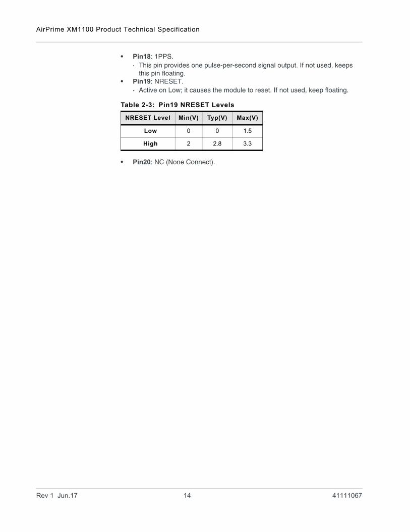
• Pin18: 1PPS.· This pin provides one pulse-per-second signal output. If not used, keeps
this pin floating.• Pin19: NRESET.
· Active on Low; it causes the module to reset. If not used, keep floating.
• Pin20: NC (None Connect).
Table 2-3: Pin19 NRESET Levels
NRESET Level Min(V) Typ(V) Max(V)
Low 0 0 1.5
High 2 2.8 3.3
Rev 1 Jun.17 14 41111067
Specifications
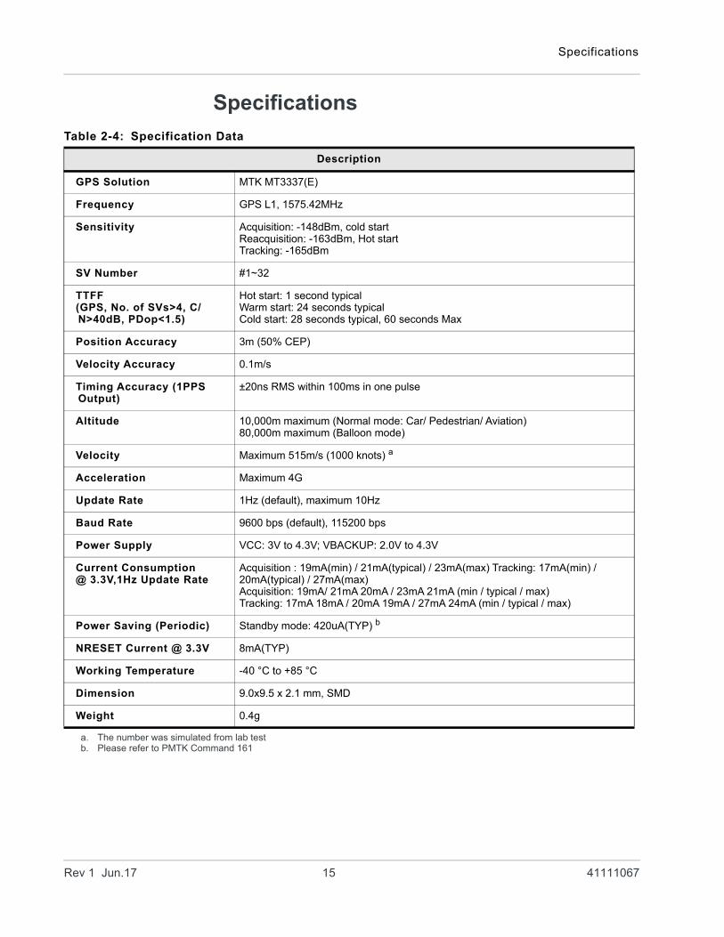
Specifications
Table 2-4: Specification Data
Description
GPS Solution MTK MT3337(E)
Frequency GPS L1, 1575.42MHz
Sensitivity Acquisition: -148dBm, cold startReacquisition: -163dBm, Hot startTracking: -165dBm
SV Number #1~32
TTFF(GPS, No. of SVs>4, C/N>40dB, PDop<1.5)
Hot start: 1 second typicalWarm start: 24 seconds typicalCold start: 28 seconds typical, 60 seconds Max
Position Accuracy 3m (50% CEP)
Velocity Accuracy 0.1m/s
Timing Accuracy (1PPS Output)
±20ns RMS within 100ms in one pulse
Altitude 10,000m maximum (Normal mode: Car/ Pedestrian/ Aviation)80,000m maximum (Balloon mode)
Velocity Maximum 515m/s (1000 knots) a
Acceleration Maximum 4G
Update Rate 1Hz (default), maximum 10Hz
Baud Rate 9600 bps (default), 115200 bps
Power Supply VCC: 3V to 4.3V; VBACKUP: 2.0V to 4.3V
Current Consumption@ 3.3V,1Hz Update Rate
Acquisition : 19mA(min) / 21mA(typical) / 23mA(max) Tracking: 17mA(min) / 20mA(typical) / 27mA(max)Acquisition: 19mA/ 21mA 20mA / 23mA 21mA (min / typical / max)Tracking: 17mA 18mA / 20mA 19mA / 27mA 24mA (min / typical / max)
Power Saving (Periodic) Standby mode: 420uA(TYP) b
NRESET Current @ 3.3V 8mA(TYP)
Working Temperature -40 °C to +85 °C
Dimension 9.0x9.5 x 2.1 mm, SMD
Weight 0.4g
a. The number was simulated from lab testb. Please refer to PMTK Command 161
Rev 1 Jun.17 15 41111067
AirPrime XM1100 Product Technical Specification
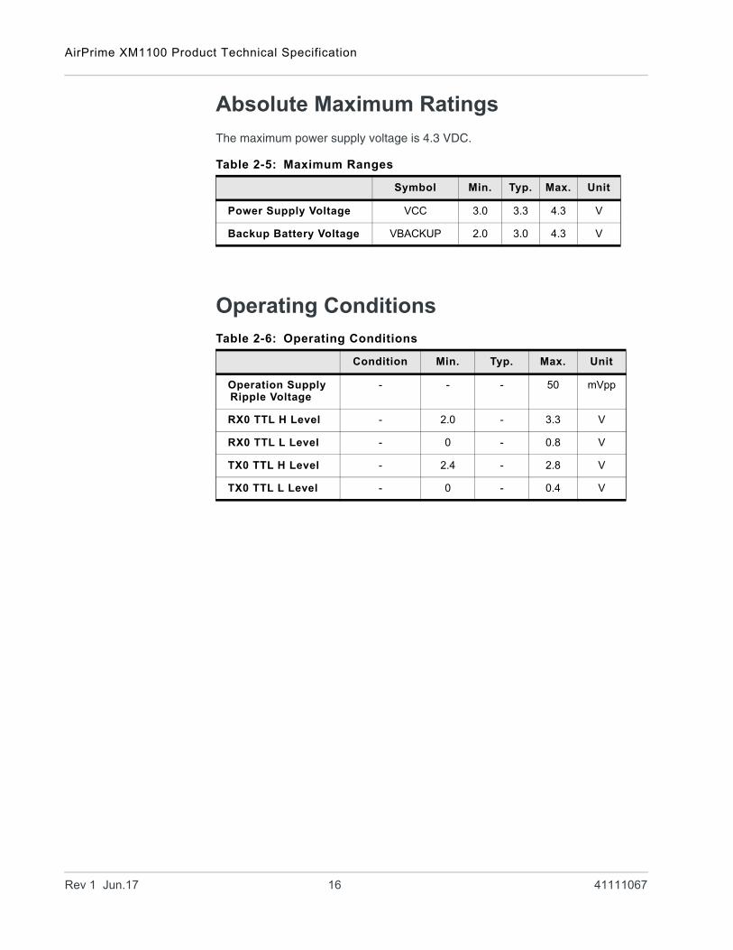
Absolute Maximum Ratings
The maximum power supply voltage is 4.3 VDC.
Operating Conditions
Table 2-5: Maximum Ranges
Symbol Min. Typ. Max. Unit
Power Supply Voltage VCC 3.0 3.3 4.3 V
Backup Battery Voltage VBACKUP 2.0 3.0 4.3 V
Table 2-6: Operating Conditions
Condition Min. Typ. Max. Unit
Operation Supply Ripple Voltage
- - - 50 mVpp
RX0 TTL H Level - 2.0 - 3.3 V
RX0 TTL L Level - 0 - 0.8 V
TX0 TTL H Level - 2.4 - 2.8 V
TX0 TTL L Level - 0 - 0.4 V
Rev 1 Jun.17 16 41111067
3
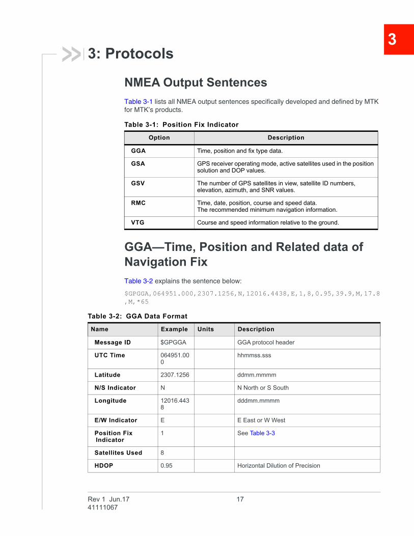
3: ProtocolsNMEA Output Sentences
Table 3-1 lists all NMEA output sentences specifically developed and defined by MTK for MTK’s products.
GGA—Time, Position and Related data of Navigation Fix
Table 3-2 explains the sentence below:
$GPGGA,064951.000,2307.1256,N,12016.4438,E,1,8,0.95,39.9,M,17.8,M,*65
Table 3-1: Position Fix Indicator
Option Description
GGA Time, position and fix type data.
GSA GPS receiver operating mode, active satellites used in the position solution and DOP values.
GSV The number of GPS satellites in view, satellite ID numbers, elevation, azimuth, and SNR values.
RMC Time, date, position, course and speed data.The recommended minimum navigation information.
VTG Course and speed information relative to the ground.
Table 3-2: GGA Data Format
Name Example Units Description
Message ID $GPGGA GGA protocol header
UTC Time 064951.000
hhmmss.sss
Latitude 2307.1256 ddmm.mmmm
N/S Indicator N N North or S South
Longitude 12016.4438
dddmm.mmmm
E/W Indicator E E East or W West
Position Fix Indicator
1 See Table 3-3
Satellites Used 8
HDOP 0.95 Horizontal Dilution of Precision
Rev 1 Jun.17 1741111067
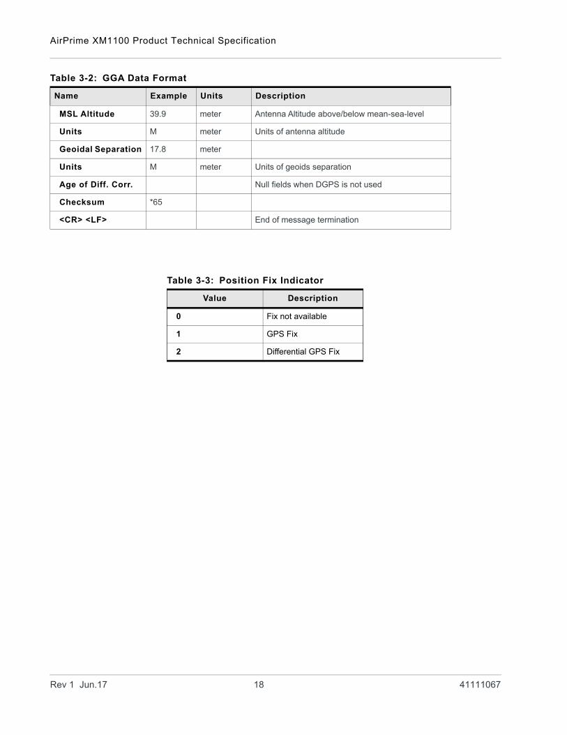
AirPrime XM1100 Product Technical Specification
MSL Altitude 39.9 meter Antenna Altitude above/below mean-sea-level
Units M meter Units of antenna altitude
Geoidal Separation 17.8 meter
Units M meter Units of geoids separation
Age of Diff. Corr. Null fields when DGPS is not used
Checksum *65
<CR> <LF> End of message termination
Table 3-2: GGA Data Format
Name Example Units Description
Table 3-3: Position Fix Indicator
Value Description
0 Fix not available
1 GPS Fix
2 Differential GPS Fix
Rev 1 Jun.17 18 41111067
Protocols
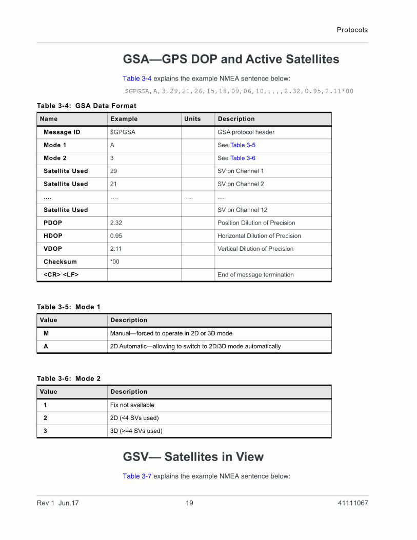
GSA—GPS DOP and Active Satellites
Table 3-4 explains the example NMEA sentence below:
$GPGSA,A,3,29,21,26,15,18,09,06,10,,,,,2.32,0.95,2.11*00
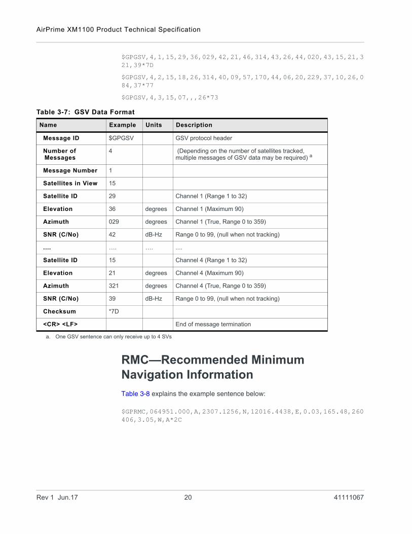
GSV— Satellites in View
Table 3-7 explains the example NMEA sentence below:
Table 3-4: GSA Data Format
Name Example Units Description
Message ID $GPGSA GSA protocol header
Mode 1 A See Table 3-5
Mode 2 3 See Table 3-6
Satellite Used 29 SV on Channel 1
Satellite Used 21 SV on Channel 2
.... …. …. ....
Satellite Used SV on Channel 12
PDOP 2.32 Position Dilution of Precision
HDOP 0.95 Horizontal Dilution of Precision
VDOP 2.11 Vertical Dilution of Precision
Checksum *00
<CR> <LF> End of message termination
Table 3-5: Mode 1
Value Description
M Manual—forced to operate in 2D or 3D mode
A 2D Automatic—allowing to switch to 2D/3D mode automatically
Table 3-6: Mode 2
Value Description
1 Fix not available
2 2D (<4 SVs used)
3 3D (>=4 SVs used)
Rev 1 Jun.17 19 41111067
AirPrime XM1100 Product Technical Specification
$GPGSV,4,1,15,29,36,029,42,21,46,314,43,26,44,020,43,15,21,321,39*7D
$GPGSV,4,2,15,18,26,314,40,09,57,170,44,06,20,229,37,10,26,084,37*77
$GPGSV,4,3,15,07,,,26*73
RMC—Recommended Minimum Navigation Information
Table 3-8 explains the example sentence below:
$GPRMC,064951.000,A,2307.1256,N,12016.4438,E,0.03,165.48,260406,3.05,W,A*2C
Table 3-7: GSV Data Format
Name Example Units Description
Message ID $GPGSV GSV protocol header
Number of Messages
4 (Depending on the number of satellites tracked, multiple messages of GSV data may be required) a
Message Number 1
Satellites in View 15
Satellite ID 29 Channel 1 (Range 1 to 32)
Elevation 36 degrees Channel 1 (Maximum 90)
Azimuth 029 degrees Channel 1 (True, Range 0 to 359)
SNR (C/No) 42 dB-Hz Range 0 to 99, (null when not tracking)
.... …. …. ....
Satellite ID 15 Channel 4 (Range 1 to 32)
Elevation 21 degrees Channel 4 (Maximum 90)
Azimuth 321 degrees Channel 4 (True, Range 0 to 359)
SNR (C/No) 39 dB-Hz Range 0 to 99, (null when not tracking)
Checksum *7D
<CR> <LF> End of message termination
a. One GSV sentence can only receive up to 4 SVs
Rev 1 Jun.17 20 41111067

Protocols
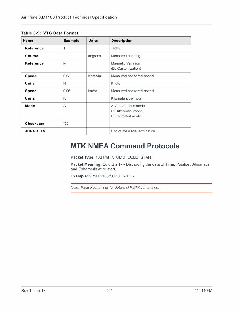
VTG—Course and Speed information Relating to the Ground
Table 3-9 explains the example sentence below:
$GPVTG,165.48,T,,M,0.03,N,0.06,K,A*37
Table 3-8: RMC Data Format
Name Example Units Description
Message ID $GPRMC RMC protocol header
UTC Time 064951.000 hhmmss.sss
Status A A: data valid
V: data not valid
Latitude 2307.1256 ddmm.mmmm
N/S Indicator N N: North
S: South
Longitude 12016.4438 dddmm.mmmm
E/W Indicator E E: East
W: West
Speed over Ground
0.03 knots
Course over Ground
165.48 degrees TRUE
Date 260406 ddmmyy
Magnetic Variation
Mode A A: Autonomous mode
D: Differential mode
E: Estimated mode
Checksum *2C
<CR> <LF> End of message termination
Table 3-9: VTG Data Format
Name Example Units Description
Message ID $GPVTG VTG protocol header
Course 165.48 degrees Measured heading
Rev 1 Jun.17 21 41111067
AirPrime XM1100 Product Technical Specification
MTK NMEA Command Protocols
Packet Type: 103 PMTK_CMD_COLD_START
Packet Meaning: Cold Start --- Discarding the data of Time, Position, Almanacs and Ephemeris at re-start.
Example: $PMTK103*30<CR><LF>
Note: Please contact us for details of PMTK commands.
Reference T TRUE
Course degrees Measured heading
Reference M Magnetic Variation
(By Customization)
Speed 0.03 Knots/hr Measured horizontal speed
Units N Knots
Speed 0.06 km/hr Measured horizontal speed
Units K Kilometers per hour
Mode A A: Autonomous mode
D: Differential mode
E: Estimated mode
Checksum *37
<CR> <LF> End of message termination
Table 3-9: VTG Data Format
Name Example Units Description
Rev 1 Jun.17 22 41111067
4
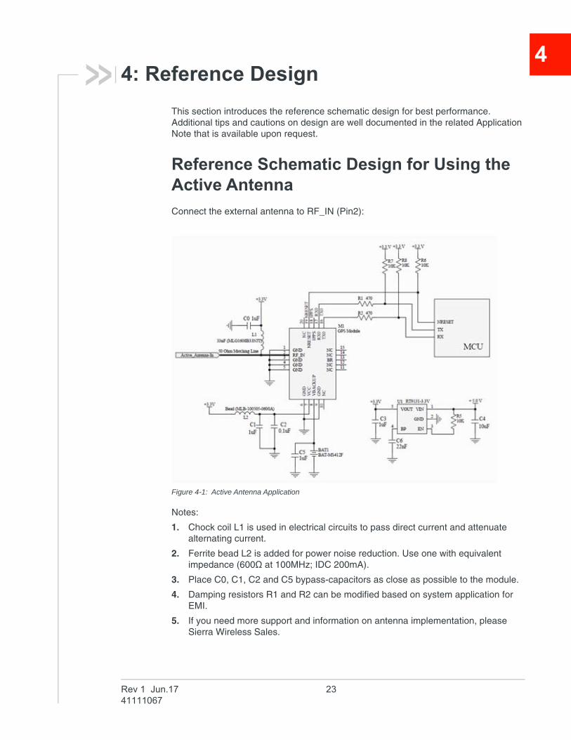
4: Reference DesignThis section introduces the reference schematic design for best performance. Additional tips and cautions on design are well documented in the related Application Note that is available upon request.
Reference Schematic Design for Using the Active Antenna
Connect the external antenna to RF_IN (Pin2):
Figure 4-1: Active Antenna Application
Notes:
1. Chock coil L1 is used in electrical circuits to pass direct current and attenuate alternating current.
2. Ferrite bead L2 is added for power noise reduction. Use one with equivalent impedance (600Ω at 100MHz; IDC 200mA).
3. Place C0, C1, C2 and C5 bypass-capacitors as close as possible to the module.
4. Damping resistors R1 and R2 can be modified based on system application for EMI.
5. If you need more support and information on antenna implementation, please Sierra Wireless Sales.
Rev 1 Jun.17 2341111067
AirPrime XM1100 Product Technical Specification
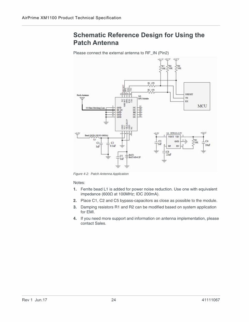
Schematic Reference Design for Using the Patch Antenna
Please connect the external antenna to RF_IN (Pin2)
Figure 4-2: Patch Antenna Application
Notes:
1. Ferrite bead L1 is added for power noise reduction. Use one with equivalent impedance (600Ω at 100MHz; IDC 200mA).
2. Place C1, C2 and C5 bypass-capacitors as close as possible to the module.
3. Damping resistors R1 and R2 can be modified based on system application for EMI.
4. If you need more support and information on antenna implementation, please contact Sales.
Rev 1 Jun.17 24 41111067
5
5: Packing and HandlingThe XM1100, like any other SMD device, is sensitive to moisture, electrostatic discharge and temperature. By following the standards of storage and handling outlined in this document for Sierra Wireless’ modules, the chances of them being damaged during production setup can be reduced. This section will walk you through the basics on how Sierra Wireless packages the modules, to ensure that the modules arrive at their destination without any damages or deterioration for performance quality. Cautionary steps prior to the surface mount process are also included in the cautionary notes.
Important: Please read the following sections carefully to avoid possible damage.
Important: GPS receiver modules are highly electrostatic-sensitive devices. Without ESD protections or without proper handling may lead to permanent damage to the modules.
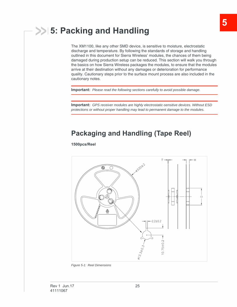
Packaging and Handling (Tape Reel)
1500pcs/Reel
Figure 5-1: Reel Dimensions
Rev 1 Jun.17 2541111067
AirPrime XM1100 Product Technical Specification
Specs:
H: 24.5±1.5,
T: 2.2±0.2,
D: 99±1.5
Note: 13” Reel;
Material: P.S
Unit: (mm)
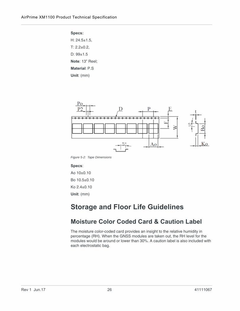
Figure 5-2: Tape Dimensions
Specs:
Ao 10±0.10
Bo 10.5±0.10
Ko 2.4±0.10
Unit: (mm)
Storage and Floor Life Guidelines
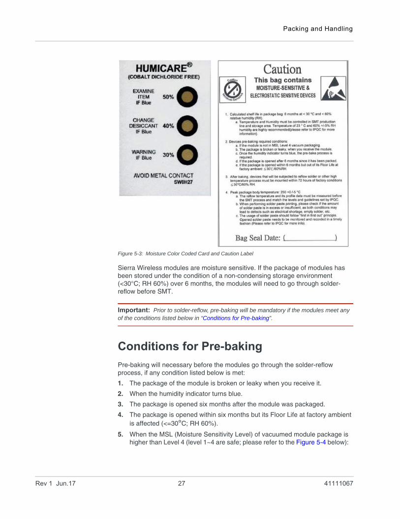
Moisture Color Coded Card & Caution Label
The moisture color-coded card provides an insight to the relative humidity in percentage (RH). When the GNSS modules are taken out, the RH level for the modules would be around or lower than 30%. A caution label is also included with each electrostatic bag.
Rev 1 Jun.17 26 41111067
Packing and Handling
Figure 5-3: Moisture Color Coded Card and Caution Label
Sierra Wireless modules are moisture sensitive. If the package of modules has been stored under the condition of a non-condensing storage environment (<30°C; RH 60%) over 6 months, the modules will need to go through solder-reflow before SMT.
Important: Prior to solder-reflow, pre-baking will be mandatory if the modules meet any of the conditions listed below in “Conditions for Pre-baking”.
Conditions for Pre-baking
Pre-baking will necessary before the modules go through the solder-reflow process, if any condition listed below is met:
1. The package of the module is broken or leaky when you receive it.
2. When the humidity indicator turns blue.
3. The package is opened six months after the module was packaged.
4. The package is opened within six months but its Floor Life at factory ambient is affected (<=30°C; RH 60%).
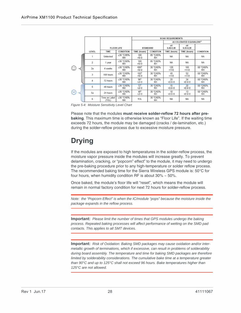
5. When the MSL (Moisture Sensitivity Level) of vacuumed module package is higher than Level 4 (level 1~4 are safe; please refer to the Figure 5-4 below):
Rev 1 Jun.17 27 41111067
AirPrime XM1100 Product Technical Specification
Figure 5-4: Moisture Sensitivity Level Chart
Please note that the modules must receive solder-reflow 72 hours after pre-baking. This maximum time is otherwise known as “Floor Life”. If the waiting time exceeds 72 hours, the module may be damaged (cracks / de-lamination, etc.) during the solder-reflow process due to excessive moisture pressure.
Drying
If the modules are exposed to high temperatures in the solder-reflow process, the moisture vapor pressure inside the modules will increase greatly. To prevent delamination, cracking, or “popcorn” effect” to the module, it may need to undergo the pre-baking procedure prior to any high-temperature or solder reflow process. The recommended baking time for the Sierra Wireless GPS module is: 50°C for four hours, when humidity condition RF is about 30% ~ 50%.
Once baked, the module’s floor life will “reset”, which means the module will remain in normal factory condition for next 72 hours for solder-reflow process.
Note: the “Popcorn Effect” is when the IC/module “pops” because the moisture inside the package expands in the reflow process.
Important: Please limit the number of times that GPS modules undergo the baking process. Repeated baking processes will affect performance of wetting on the SMD pad contacts. This applies to all SMT devices.
Important: Risk of Oxidation: Baking SMD packages may cause oxidation and/or inter-metallic growth of terminations, which if excessive, can result in problems of solderability during board assembly. The temperature and time for baking SMD packages are therefore limited by solderability considerations. The cumulative bake time at a temperature greater than 90°C and up to 125°C shall not exceed 96 hours. Bake temperatures higher than 125°C are not allowed.
Rev 1 Jun.17 28 41111067
Packing and Handling
ESD Handling
Warning: Please follow the precautions addressed below carefully to prevent severe damage to GPS modules.
Sierra Wireless modules are sensitive to electrostatic discharges and thus are Electrostatic Sensitive Devices (ESD). Handle the GPS modules particularly to its patch antenna (if included) and RF_IN pin carefully. Please follow the standard ESD safety practices stated below:
• Unless there is a galvanic coupling between the local GND and the PCB GND, then the first point of contact when handling the PCB shall always be between the local GND and PCB GND.
• Before working with the RF_IN pin, please make sure the GND is connected.• When working with the RF_IN pin, do not contact any charged capacitors or
materials that can easily develop or store charges such as the patch antenna, coax cable, or soldering iron.
• Please do not touch the mounted patch antenna, to prevent electrostatic discharge from the RF input
• When soldering RF_IN pin, please make sure to use an ESD safe soldering iron tip.
Rev 1 Jun.17 29 41111067
6
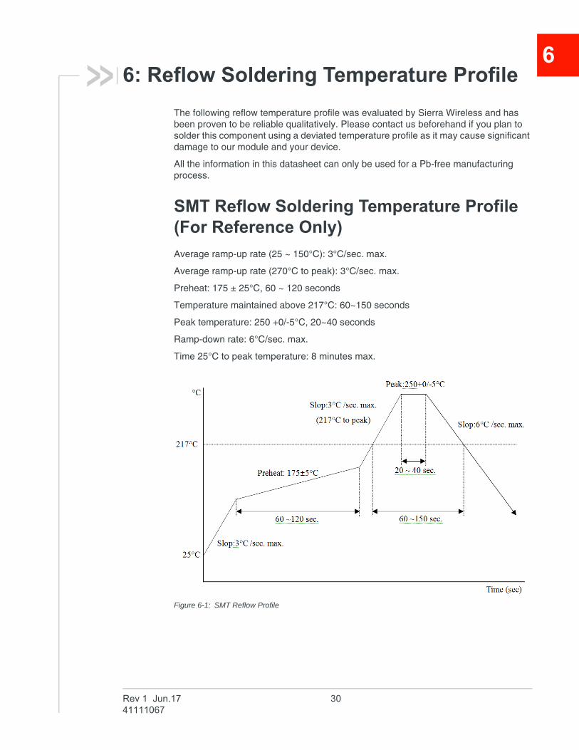
6: Reflow Soldering Temperature ProfileThe following reflow temperature profile was evaluated by Sierra Wireless and has been proven to be reliable qualitatively. Please contact us beforehand if you plan to solder this component using a deviated temperature profile as it may cause significant damage to our module and your device.
All the information in this datasheet can only be used for a Pb-free manufacturing process.
SMT Reflow Soldering Temperature Profile (For Reference Only)
Average ramp-up rate (25 ~ 150°C): 3°C/sec. max.
Average ramp-up rate (270°C to peak): 3°C/sec. max.
Preheat: 175 ± 25°C, 60 ~ 120 seconds
Temperature maintained above 217°C: 60~150 seconds
Peak temperature: 250 +0/-5°C, 20~40 seconds
Ramp-down rate: 6°C/sec. max.
Time 25°C to peak temperature: 8 minutes max.
Figure 6-1: SMT Reflow Profile
Rev 1 Jun.17 3041111067
Reflow Soldering Temperature Profile
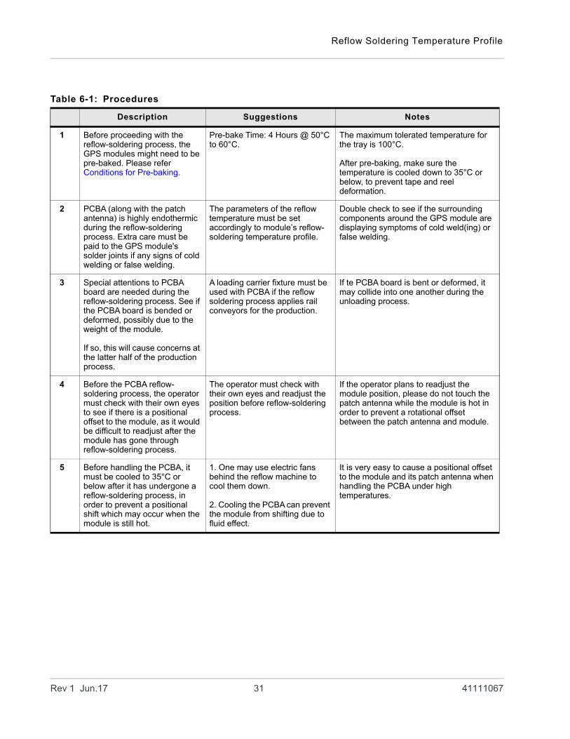
Table 6-1: Procedures
Description Suggestions Notes
1 Before proceeding with the reflow-soldering process, the GPS modules might need to be pre-baked. Please refer Conditions for Pre-baking.
Pre-bake Time: 4 Hours @ 50°C to 60°C.
The maximum tolerated temperature for the tray is 100°C.
After pre-baking, make sure the temperature is cooled down to 35°C or below, to prevent tape and reel deformation.
2 PCBA (along with the patch antenna) is highly endothermic during the reflow-soldering process. Extra care must be paid to the GPS module's solder joints if any signs of cold welding or false welding.
The parameters of the reflow temperature must be set accordingly to module’s reflow-soldering temperature profile.
Double check to see if the surrounding components around the GPS module are displaying symptoms of cold weld(ing) or false welding.
3 Special attentions to PCBA board are needed during the reflow-soldering process. See if the PCBA board is bended or deformed, possibly due to the weight of the module.
If so, this will cause concerns at the latter half of the production process.
A loading carrier fixture must be used with PCBA if the reflow soldering process applies rail conveyors for the production.
If te PCBA board is bent or deformed, it may collide into one another during the unloading process.
4 Before the PCBA reflow-soldering process, the operator must check with their own eyes to see if there is a positional offset to the module, as it would be difficult to readjust after the module has gone through reflow-soldering process.
The operator must check with their own eyes and readjust the position before reflow-soldering process.
If the operator plans to readjust the module position, please do not touch the patch antenna while the module is hot in order to prevent a rotational offset between the patch antenna and module.
5 Before handling the PCBA, it must be cooled to 35°C or below after it has undergone a reflow-soldering process, in order to prevent a positional shift which may occur when the module is still hot.
1. One may use electric fans behind the reflow machine to cool them down.
2. Cooling the PCBA can prevent the module from shifting due to fluid effect.
It is very easy to cause a positional offset to the module and its patch antenna when handling the PCBA under high temperatures.
Rev 1 Jun.17 31 41111067
AirPrime XM1100 Product Technical Specification
Other Cautionary Notes on the Reflow-Soldering Process:
1. The module may need pre-baking before going through the SMT solder reflow process. Please refer to Conditions for Pre-baking.
2. The usage of solder paste should follow the “FIFO (First-in-First-out)” principle. Opened solder paste needs to be monitored and recorded in a timely manner (please refer to IPQC standards for related documentation and examples).
3. Temperature and humidity must be controlled within an SMT production line and storage area. A temperature of 23°C, 60±5% RH humidity is recom-mended (please refer to IPQC standards for related documentation and examples).
4. When performing solder paste printing, please notice if the amount of solder paste is excessive or insufficient, as both conditions may lead to defects such as electrical shortage, empty solder, and etc.
5. Make sure the vacuum mouthpiece is able to bear the weight of the GPS module to prevent positional shift during the loading process.
6. Before the PCBA goes through the reflow-soldering process, the operator must visually check if there is a positional offset to the module.
7. The reflow temperature and its profile data must be measured before the SMT process and match the levels and guidelines set by IPQC.
8. If the SMT protection line is running a double-sided process for PCBA, please process the GPS module during the second pass only to avoid repeated reflow exposures of the GPS module. Please contact Sierra Wireless beforehand if you must process the GPS module during the first pass of a double-side process.
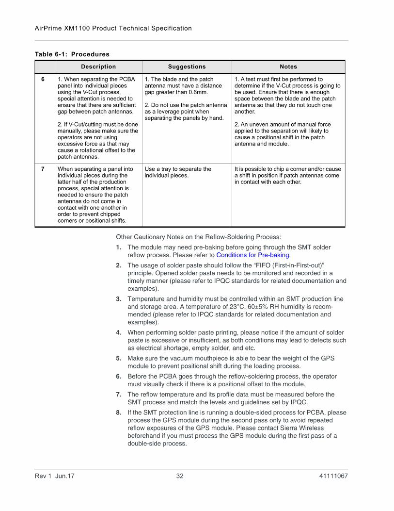
6 1. When separating the PCBA panel into individual pieces using the V-Cut process, special attention is needed to ensure that there are sufficient gap between patch antennas.
2. If V-Cut/cutting must be done manually, please make sure the operators are not using excessive force as that may cause a rotational offset to the patch antennas.
1. The blade and the patch antenna must have a distance gap greater than 0.6mm.
2. Do not use the patch antenna as a leverage point when separating the panels by hand.
1. A test must first be performed to determine if the V-Cut process is going to be used. Ensure that there is enough space between the blade and the patch antenna so that they do not touch one another.
2. An uneven amount of manual force applied to the separation will likely to cause a positional shift in the patch antenna and module.
7 When separating a panel into individual pieces during the latter half of the production process, special attention is needed to ensure the patch antennas do not come in contact with one another in order to prevent chipped corners or positional shifts.
Use a tray to separate the individual pieces.
It is possible to chip a corner and/or cause a shift in position if patch antennas come in contact with each other.
Table 6-1: Procedures
Description Suggestions Notes
Rev 1 Jun.17 32 41111067
Reflow Soldering Temperature Profile
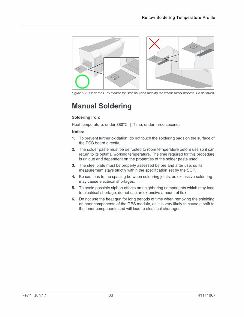
Figure 6-2: Place the GPS module top side up when running the reflow-solder process. Do not invert.
Manual Soldering
Soldering iron:
Heat temperature: under 380°C | Time: under three seconds.
Notes:
1. To prevent further oxidation, do not touch the soldering pads on the surface of the PCB board directly.
2. The solder paste must be defrosted to room temperature before use so it can return to its optimal working temperature. The time required for this procedure is unique and dependent on the properties of the solder paste used.
3. The steel plate must be properly assessed before and after use, so its measurement stays strictly within the specification set by the SOP.
4. Be cautious to the spacing between soldering joints, as excessive soldering may cause electrical shortages.
5. To avoid possible siphon effects on neighboring components which may lead to electrical shortage, do not use an extensive amount of flux.
6. Do not use the heat gun for long periods of time when removing the shielding or inner components of the GPS module, as it is very likely to cause a shift to the inner components and will lead to electrical shortages.
Rev 1 Jun.17 33 41111067