PRODUCT SUPPORT MANUAL RCL-100D // Remote … · The sleek design and modern construction of the...
23
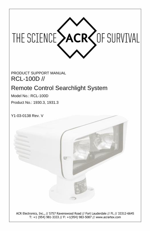
ACR Electronics, Inc., // 5757 Ravenswood Road // Fort Lauderdale // FL // 33312-6645 T: +1 (954) 981-3333 // F: +1(954) 983-5087 // www.acrartex.com PRODUCT SUPPORT MANUAL RCL-100D // Remote Control Searchlight System Model No.: RCL-100D Product No.: 1930.3, 1931.3 Y1-03-0138 Rev. V
Transcript of PRODUCT SUPPORT MANUAL RCL-100D // Remote … · The sleek design and modern construction of the...
Y1-03-0138U i
ACR Electronics, Inc., // 5757 Ravenswood Road // Fort Lauderdale // FL // 33312-6645 T: +1 (954) 981-3333 // F: +1(954) 983-5087 // www.acrartex.com
PRODUCT SUPPORT MANUAL
RCL-100D //
Remote Control Searchlight System
Model No.: RCL-100D
Product No.: 1930.3, 1931.3
Y1-03-0138 Rev. V
Y1-03-0138V 2
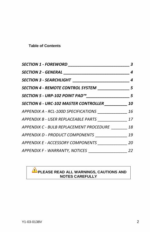
Table of Contents
SECTION 1 - FOREWORD ___________________________ 3
SECTION 2 - GENERAL _____________________________ 4
SECTION 3 - SEARCHLIGHT _________________________ 4
SECTION 4 - REMOTE CONTROL SYSTEM ______________ 5
SECTION 5 - URP-102 POINT PAD™ ___________________ 5
SECTION 6 - URC-102 MASTER CONTROLLER __________ 10
APPENDIX A - RCL-100D SPECIFICATIONS _____________ 16
APPENDIX B - USER REPLACEABLE PARTS _____________ 17
APPENDIX C - BULB REPLACEMENT PROCEDURE _______ 18
APPENDIX D - PRODUCT COMPONENTS ______________ 19
APPENDIX E - ACCESSORY COMPONENTS _____________ 20
APPENDIX F - WARRANTY, NOTICES _________________ 22
PLEASE READ ALL WARNINGS, CAUTIONS AND NOTES CAREFULLY
Y1-03-0138V 3
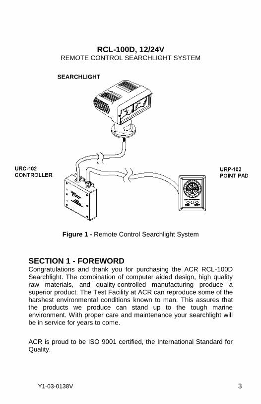
RCL-100D, 12/24V REMOTE CONTROL SEARCHLIGHT SYSTEM
Figure 1 - Remote Control Searchlight System
SECTION 1 - FOREWORD Congratulations and thank you for purchasing the ACR RCL-100D Searchlight. The combination of computer aided design, high quality raw materials, and quality-controlled manufacturing produce a superior product. The Test Facility at ACR can reproduce some of the harshest environmental conditions known to man. This assures that the products we produce can stand up to the tough marine environment. With proper care and maintenance your searchlight will be in service for years to come.
ACR is proud to be ISO 9001 certified, the International Standard for Quality.
SEARCHLIGHT
Y1-03-0138V 4
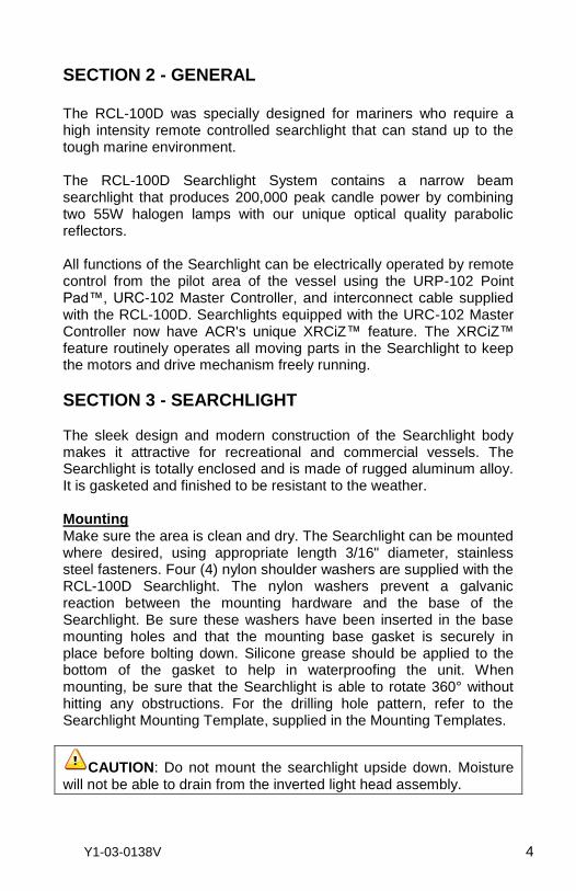
SECTION 2 - GENERAL
The RCL-100D was specially designed for mariners who require a high intensity remote controlled searchlight that can stand up to the tough marine environment. The RCL-100D Searchlight System contains a narrow beam searchlight that produces 200,000 peak candle power by combining two 55W halogen lamps with our unique optical quality parabolic reflectors. All functions of the Searchlight can be electrically operated by remote control from the pilot area of the vessel using the URP-102 Point Pad™, URC-102 Master Controller, and interconnect cable supplied with the RCL-100D. Searchlights equipped with the URC-102 Master Controller now have ACR's unique XRCiZ™ feature. The XRCiZ™ feature routinely operates all moving parts in the Searchlight to keep the motors and drive mechanism freely running.
SECTION 3 - SEARCHLIGHT The sleek design and modern construction of the Searchlight body makes it attractive for recreational and commercial vessels. The Searchlight is totally enclosed and is made of rugged aluminum alloy. It is gasketed and finished to be resistant to the weather. Mounting Make sure the area is clean and dry. The Searchlight can be mounted where desired, using appropriate length 3/16" diameter, stainless steel fasteners. Four (4) nylon shoulder washers are supplied with the RCL-100D Searchlight. The nylon washers prevent a galvanic reaction between the mounting hardware and the base of the Searchlight. Be sure these washers have been inserted in the base mounting holes and that the mounting base gasket is securely in place before bolting down. Silicone grease should be applied to the bottom of the gasket to help in waterproofing the unit. When mounting, be sure that the Searchlight is able to rotate 360° without hitting any obstructions. For the drilling hole pattern, refer to the Searchlight Mounting Template, supplied in the Mounting Templates.
CAUTION: Do not mount the searchlight upside down. Moisture will not be able to drain from the inverted light head assembly.
Y1-03-0138V 5
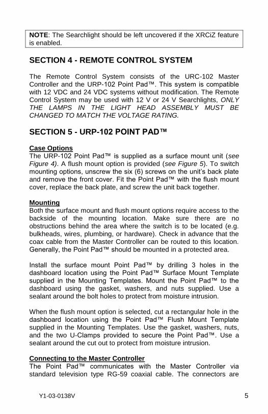
NOTE: The Searchlight should be left uncovered if the XRCiZ feature is enabled.
SECTION 4 - REMOTE CONTROL SYSTEM The Remote Control System consists of the URC-102 Master Controller and the URP-102 Point Pad™. This system is compatible with 12 VDC and 24 VDC systems without modification. The Remote Control System may be used with 12 V or 24 V Searchlights, ONLY THE LAMPS IN THE LIGHT HEAD ASSEMBLY MUST BE CHANGED TO MATCH THE VOLTAGE RATING.
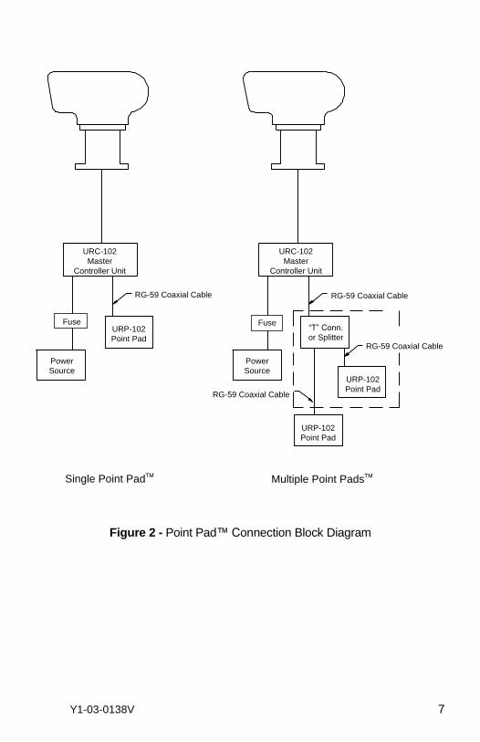
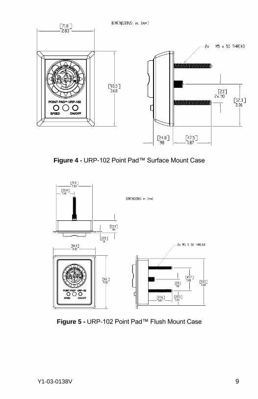
SECTION 5 - URP-102 POINT PAD™ Case Options The URP-102 Point Pad™ is supplied as a surface mount unit (see Figure 4). A flush mount option is provided (see Figure 5). To switch mounting options, unscrew the six (6) screws on the unit’s back plate and remove the front cover. Fit the Point Pad™ with the flush mount cover, replace the back plate, and screw the unit back together. Mounting Both the surface mount and flush mount options require access to the backside of the mounting location. Make sure there are no obstructions behind the area where the switch is to be located (e.g. bulkheads, wires, plumbing, or hardware). Check in advance that the coax cable from the Master Controller can be routed to this location. Generally, the Point Pad™ should be mounted in a protected area. Install the surface mount Point Pad™ by drilling 3 holes in the dashboard location using the Point Pad™ Surface Mount Template supplied in the Mounting Templates. Mount the Point Pad™ to the dashboard using the gasket, washers, and nuts supplied. Use a sealant around the bolt holes to protect from moisture intrusion. When the flush mount option is selected, cut a rectangular hole in the dashboard location using the Point Pad™ Flush Mount Template supplied in the Mounting Templates. Use the gasket, washers, nuts, and the two U-Clamps provided to secure the Point Pad™. Use a sealant around the cut out to protect from moisture intrusion. Connecting to the Master Controller The Point Pad™ communicates with the Master Controller via standard television type RG-59 coaxial cable. The connectors are
Y1-03-0138V 6
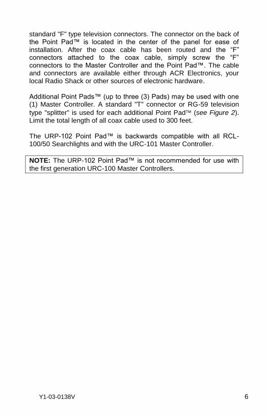
standard "F" type television connectors. The connector on the back of the Point Pad™ is located in the center of the panel for ease of installation. After the coax cable has been routed and the “F” connectors attached to the coax cable, simply screw the “F” connectors to the Master Controller and the Point Pad™. The cable and connectors are available either through ACR Electronics, your local Radio Shack or other sources of electronic hardware. Additional Point Pads™ (up to three (3) Pads) may be used with one (1) Master Controller. A standard "T" connector or RG-59 television
type "splitter" is used for each additional Point Pad (see Figure 2). Limit the total length of all coax cable used to 300 feet. The URP-102 Point Pad™ is backwards compatible with all RCL-100/50 Searchlights and with the URC-101 Master Controller.
NOTE: The URP-102 Point Pad™ is not recommended for use with
the first generation URC-100 Master Controllers.
Y1-03-0138V 7
Figure 2 - Point Pad™ Connection Block Diagram
URP-102
Point Pad
URP-102
Point Pad
URP-102
Point Pad
URC-102
Master
Controller Unit
URC-102
Master
Controller Unit
Power
Source
Power
Source
RG-59 Coaxial Cable
RG-59 Coaxial Cable
RG-59 Coaxial Cable
RG-59 Coaxial Cable
Fuse Fuse“T” Conn.
or Splitter
Single Point Pad Multiple Point Pads
Y1-03-0138V 8
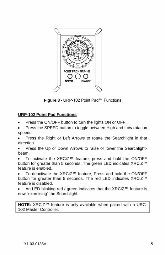
Figure 3 - URP-102 Point Pad™ Functions
URP-102 Point Pad Functions
Press the ON/OFF button to turn the lights ON or OFF.
Press the SPEED button to toggle between High and Low rotation speeds.
Press the Right or Left Arrows to rotate the Searchlight in that direction.
Press the Up or Down Arrows to raise or lower the Searchlight-beam.
To activate the XRCiZ™ feature, press and hold the ON/OFF button for greater than 5 seconds. The green LED indicates XRCiZ™ feature is enabled.
To deactivate the XRCiZ™ feature, Press and hold the ON/OFF button for greater than 5 seconds. The red LED indicates XRCiZ™ feature is disabled.
An LED blinking red / green indicates that the XRCiZ™ feature is now “exercising” the Searchlight.
NOTE: XRCiZ™ feature is only available when paired with a URC-102 Master Controller.
Y1-03-0138V 9
Figure 4 - URP-102 Point Pad™ Surface Mount Case
Figure 5 - URP-102 Point Pad™ Flush Mount Case
Y1-03-0138V 10
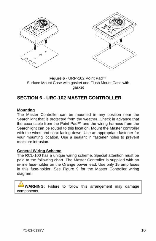
Figure 6 - URP-102 Point Pad™
Surface Mount Case with gasket and Flush Mount Case with gasket
SECTION 6 - URC-102 MASTER CONTROLLER
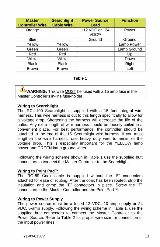
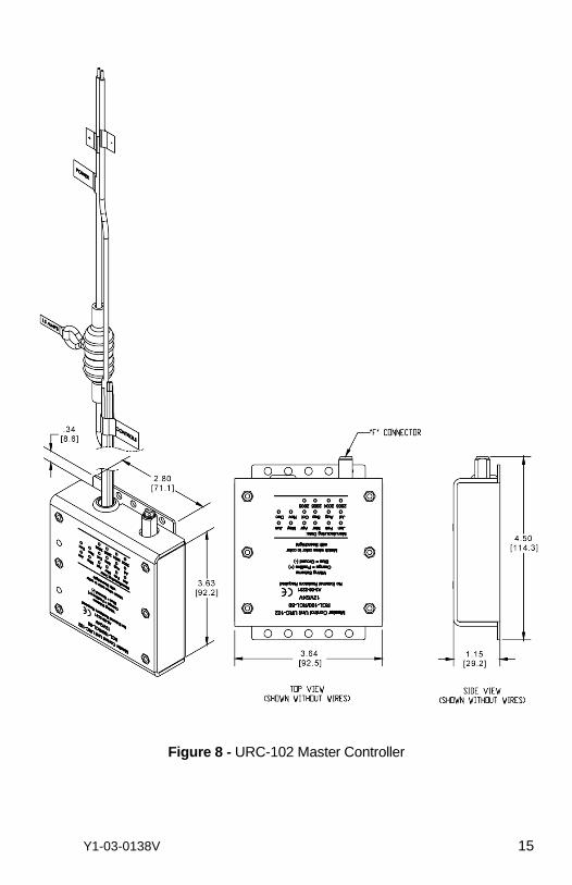
Mounting The Master Controller can be mounted in any position near the Searchlight that is protected from the weather. Check in advance that the coax cable from the Point Pad™ and the wiring harness from the Searchlight can be routed to this location. Mount the Master controller with the wires and coax facing down. Use an appropriate fastener for your mounting location. Use a sealant in fastener holes to prevent moisture intrusion. General Wiring Scheme The RCL-100 has a unique wiring scheme. Special attention must be paid to the following chart. The Master Controller is supplied with an in-line fuse-holder on the Orange power lead. Use only 15 amp fuses in this fuse-holder. See Figure 9 for the Master Controller wiring diagram.
WARNING: Failure to follow this arrangement may damage components.
Y1-03-0138V 11
Master Controller Wire
Searchlight Cable Wire
Power Source Lead
Function
Orange +12 VDC or +24 VDC**
Power
Blue Ground Ground
Yellow Yellow Lamp Power
Green Green Lamp Ground
Red Red Up
White White Down
Black Black Right
Brown Brown Left
Table 1
WARNING: This wire MUST be fused with a 15 amp fuse in the Master Controller's in-line fuse-holder.
Wiring to Searchlight The RCL-100 Searchlight is supplied with a 15 foot integral wire harness. This wire harness is cut to this length specifically to allow for a voltage drop. Shortening the harness will decrease the life of the bulbs. Any extra length of wire harness should be loosely coiled in a convenient place. For best performance, the controller should be attached to the end of the 15' Searchlight wire harness. If you must lengthen the wire harness, use heavy duty wire to minimize the voltage drop. This is especially important for the YELLOW lamp power and GREEN lamp ground wires. Following the wiring scheme shown in Table 1 use the supplied butt connectors to connect the Master Controller to the Searchlight. Wiring to Point Pad™ The RG-59 Coax cable is supplied without the “F” connectors attached for ease of routing. After the coax has been routed, strip the insulation and crimp the “F” connectors in place. Screw the “F” connectors to the Master Controller and the Point Pad™.
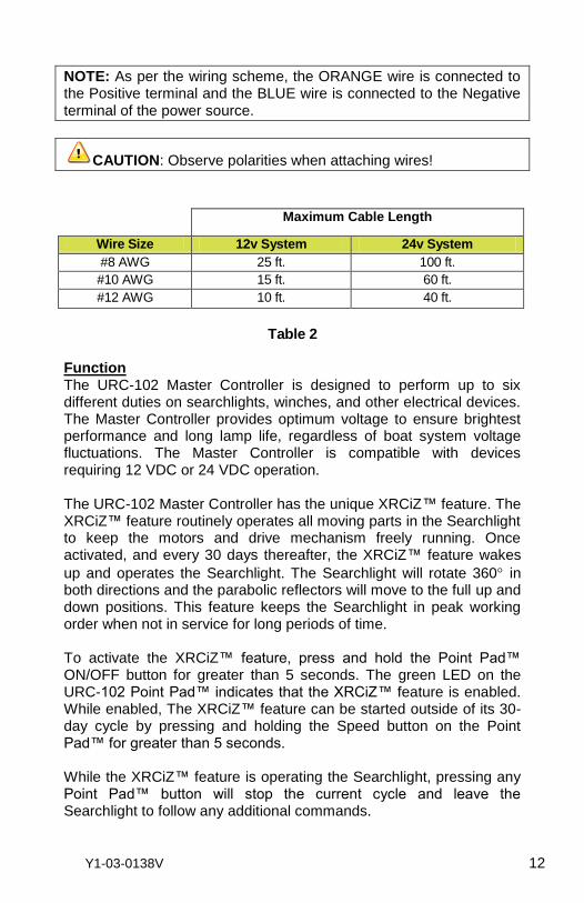
Wiring to Power Supply The power source must be a fused 12 VDC, 10-amp supply or 24 VDC, 5-amp supply. Following the wiring scheme in Table 1, use the supplied butt connectors to connect the Master Controller to the Power Source. Refer to Table 2 for proper wire size for connection of the input power lines.
Y1-03-0138V 12
NOTE: As per the wiring scheme, the ORANGE wire is connected to the Positive terminal and the BLUE wire is connected to the Negative terminal of the power source.
CAUTION: Observe polarities when attaching wires!
Maximum Cable Length
Wire Size 12v System 24v System
#8 AWG 25 ft. 100 ft.
#10 AWG 15 ft. 60 ft.
#12 AWG 10 ft. 40 ft.
Table 2
Function The URC-102 Master Controller is designed to perform up to six different duties on searchlights, winches, and other electrical devices. The Master Controller provides optimum voltage to ensure brightest performance and long lamp life, regardless of boat system voltage fluctuations. The Master Controller is compatible with devices requiring 12 VDC or 24 VDC operation. The URC-102 Master Controller has the unique XRCiZ™ feature. The XRCiZ™ feature routinely operates all moving parts in the Searchlight to keep the motors and drive mechanism freely running. Once activated, and every 30 days thereafter, the XRCiZ™ feature wakes
up and operates the Searchlight. The Searchlight will rotate 360 in both directions and the parabolic reflectors will move to the full up and down positions. This feature keeps the Searchlight in peak working order when not in service for long periods of time. To activate the XRCiZ™ feature, press and hold the Point Pad™ ON/OFF button for greater than 5 seconds. The green LED on the URC-102 Point Pad™ indicates that the XRCiZ™ feature is enabled. While enabled, The XRCiZ™ feature can be started outside of its 30-day cycle by pressing and holding the Speed button on the Point Pad™ for greater than 5 seconds. While the XRCiZ™ feature is operating the Searchlight, pressing any Point Pad™ button will stop the current cycle and leave the Searchlight to follow any additional commands.
Y1-03-0138V 13
To deactivate the XRCiZ™ feature, press and hold the Point Pad™ ON/OFF button for greater than 5 seconds. The Red LED on the URC-102 Point Pad™ indicates that the XRCiZ™ feature is disabled.
NOTE: LED feedback is not available when using RCL-100 or URC-
101 Point Pads™.
NOTE: The Searchlight should not be covered while the XRCiZ™ feature is enabled.
The URC-102 Master Controller provides optimum voltage to ensure the brightest searchlight performance and long bulb life. Also to extend lamp life, the Master Controller has a timed lamp power up feature. The searchlight lamps reach full intensity within 2 seconds. The URC-102 Master Controller has a searchlight motor timeout feature. If a Point Pad™ rotation switch (right or left) is continuously engaged for more than 50 seconds, the Master Controller will interrupt the operation until the Point Pad™ switch is disengaged. This feature will save the searchlight motor from burnout due to accidental activation. The elevation motor has similar features which will timeout in approximately 20 seconds.
Y1-03-0138V 14
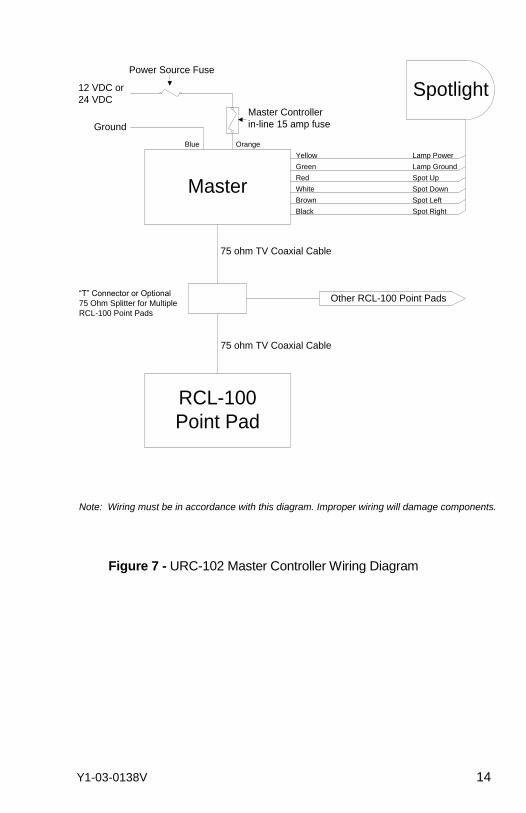
Master
RCL-100
Point Pad
Spotlight
Yellow Lamp Power
Green Lamp Ground
Red Spot Up
White Spot Down
Brown Spot Left
Black Spot Right
Other RCL-100 Point Pads
75 ohm TV Coaxial Cable
75 ohm TV Coaxial Cable
“T” Connector or Optional
75 Ohm Splitter for Multiple
RCL-100 Point Pads
Ground
Blue Orange
Note: Wiring must be in accordance with this diagram. Improper wiring will damage components.
12 VDC or
24 VDC
Master Controller
in-line 15 amp fuse
Power Source Fuse
Figure 7 - URC-102 Master Controller Wiring Diagram
Y1-03-0138V 15
Figure 8 - URC-102 Master Controller
Y1-03-0138V 16
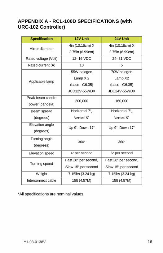
APPENDIX A - RCL-100D SPECIFICATIONS (with URC-102 Controller)
Specification 12V Unit 24V Unit
Mirror diameter 4in (10.16cm) X
2.75in (6.99cm)
4in (10.16cm) X
2.75in (6.99cm)
Rated voltage (Volt) 12- 16 VDC 24- 31 VDC
Rated current (A) 10 5
Applicable lamp
55W halogen
Lamp X 2
(base –G6.35)
JCD12V-55WDX
70W halogen
Lamp X2
(base –G6.35)
JDC24V-55WDX
Peak beam candle
power (candela) 200,000 160,000
Beam spread
(degrees)
Horizontal 7°,
Vertical 5°
Horizontal 7°,
Vertical 5°
Elevation angle
(degrees) Up 9°, Down 17° Up 9°, Down 17°
Turning angle
(degrees) 360° 360°
Elevation speed 4° per second 6° per second
Turning speed Fast 28° per second,
Slow 15° per second
Fast 28° per second,
Slow 15° per second
Weight 7.15lbs (3.24 kg) 7.15lbs (3.24 kg)
Interconnect cable 15ft (4.57M) 15ft (4.57M)
*All specifications are nominal values
Y1-03-0138U 17
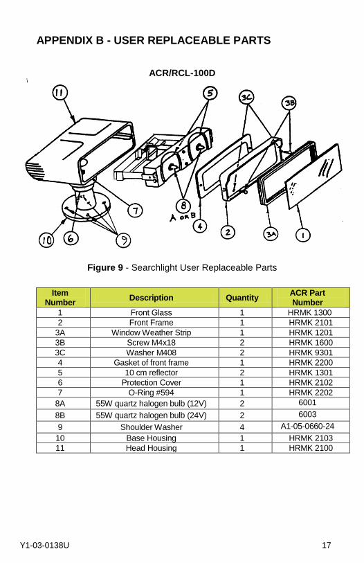
APPENDIX B - USER REPLACEABLE PARTS
ACR/RCL-100D
Figure 9 - Searchlight User Replaceable Parts
Item
Number Description Quantity
ACR Part Number
1 Front Glass 1 HRMK 1300
2 Front Frame 1 HRMK 2101
3A Window Weather Strip 1 HRMK 1201
3B Screw M4x18 2 HRMK 1600
3C Washer M408 2 HRMK 9301
4 Gasket of front frame 1 HRMK 2200
5 10 cm reflector 2 HRMK 1301
6 Protection Cover 1 HRMK 2102
7 O-Ring #594 1 HRMK 2202
8A 55W quartz halogen bulb (12V) 2 6001
8B 55W quartz halogen bulb (24V) 2 6003
9 Shoulder Washer 4 A1-05-0660-24
10 Base Housing 1 HRMK 2103
11 Head Housing 1 HRMK 2100
Y1-03-0138V 18
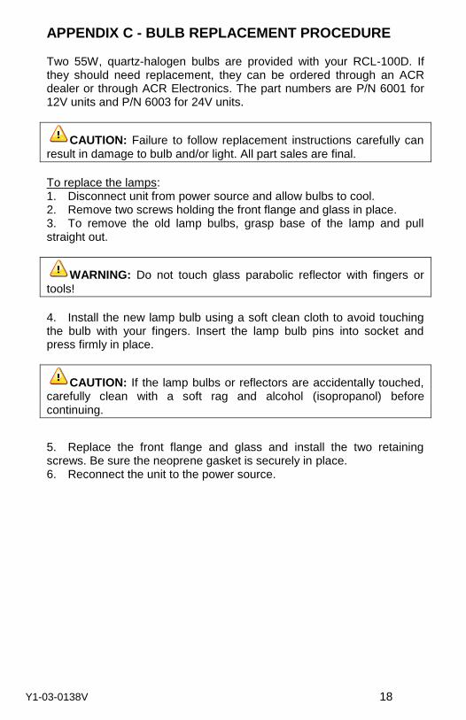
APPENDIX C - BULB REPLACEMENT PROCEDURE Two 55W, quartz-halogen bulbs are provided with your RCL-100D. If they should need replacement, they can be ordered through an ACR dealer or through ACR Electronics. The part numbers are P/N 6001 for 12V units and P/N 6003 for 24V units.
CAUTION: Failure to follow replacement instructions carefully can result in damage to bulb and/or light. All part sales are final.
To replace the lamps: 1. Disconnect unit from power source and allow bulbs to cool. 2. Remove two screws holding the front flange and glass in place. 3. To remove the old lamp bulbs, grasp base of the lamp and pull straight out.
WARNING: Do not touch glass parabolic reflector with fingers or
tools!
4. Install the new lamp bulb using a soft clean cloth to avoid touching the bulb with your fingers. Insert the lamp bulb pins into socket and press firmly in place.
CAUTION: If the lamp bulbs or reflectors are accidentally touched, carefully clean with a soft rag and alcohol (isopropanol) before continuing.
5. Replace the front flange and glass and install the two retaining screws. Be sure the neoprene gasket is securely in place. 6. Reconnect the unit to the power source.
Y1-03-0138V 19
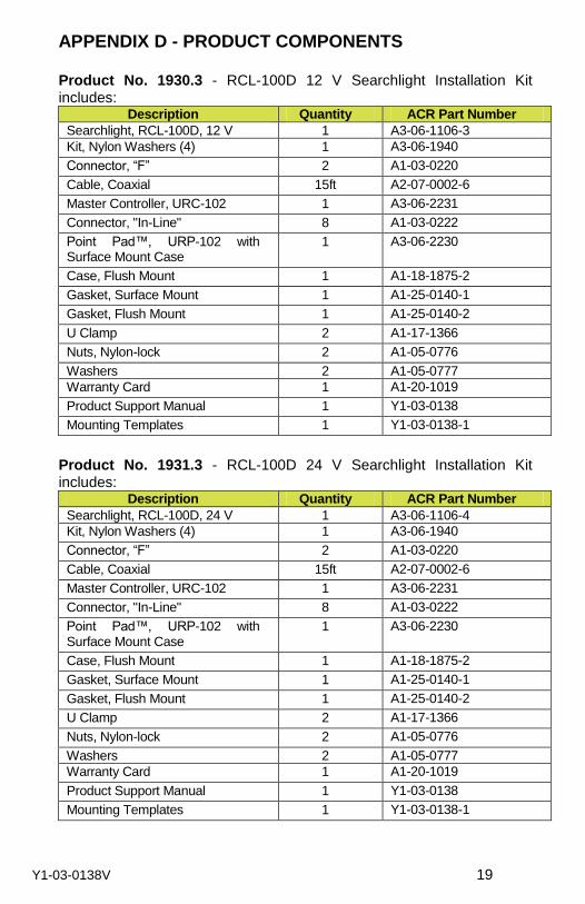
APPENDIX D - PRODUCT COMPONENTS Product No. 1930.3 - RCL-100D 12 V Searchlight Installation Kit includes:
Description Quantity ACR Part Number
Searchlight, RCL-100D, 12 V 1 A3-06-1106-3
Kit, Nylon Washers (4) 1 A3-06-1940
Connector, “F” 2 A1-03-0220
Cable, Coaxial 15ft A2-07-0002-6
Master Controller, URC-102 1 A3-06-2231
Connector, "In-Line" 8 A1-03-0222
Point Pad™, URP-102 with Surface Mount Case
1 A3-06-2230
Case, Flush Mount 1 A1-18-1875-2
Gasket, Surface Mount 1 A1-25-0140-1
Gasket, Flush Mount 1 A1-25-0140-2
U Clamp 2 A1-17-1366
Nuts, Nylon-lock 2 A1-05-0776
Washers 2 A1-05-0777
Warranty Card 1 A1-20-1019
Product Support Manual 1 Y1-03-0138
Mounting Templates 1 Y1-03-0138-1
Product No. 1931.3 - RCL-100D 24 V Searchlight Installation Kit includes:
Description Quantity ACR Part Number
Searchlight, RCL-100D, 24 V 1 A3-06-1106-4
Kit, Nylon Washers (4) 1 A3-06-1940
Connector, “F” 2 A1-03-0220
Cable, Coaxial 15ft A2-07-0002-6
Master Controller, URC-102 1 A3-06-2231
Connector, "In-Line" 8 A1-03-0222
Point Pad™, URP-102 with Surface Mount Case
1 A3-06-2230
Case, Flush Mount 1 A1-18-1875-2
Gasket, Surface Mount 1 A1-25-0140-1
Gasket, Flush Mount 1 A1-25-0140-2
U Clamp 2 A1-17-1366
Nuts, Nylon-lock 2 A1-05-0776
Washers 2 A1-05-0777
Warranty Card 1 A1-20-1019
Product Support Manual 1 Y1-03-0138
Mounting Templates 1 Y1-03-0138-1
Y1-03-0138V 20
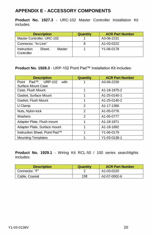
APPENDIX E - ACCESSORY COMPONENTS
Product No. 1927.3 - URC-102 Master Controller Installation Kit includes:
Description Quantity ACR Part Number
Master Controller, URC-102 1 A3-06-2231
Connector, "In-Line" 8 A1-03-0222
Instruction Sheet, Master Controller
1 Y1-06-0178
Product No. 1928.3 - URP-102 Point Pad™ Installation Kit includes:
Description Quantity ACR Part Number
Point Pad™, URP-102 with Surface Mount Case
1 A3-06-2230
Case, Flush Mount 1 A1-18-1875-2
Gasket, Surface Mount 1 A1-25-0140-1
Gasket, Flush Mount 1 A1-25-0140-2
U Clamp 2 A1-17-1366
Nuts, Nylon-lock 2 A1-05-0776
Washers 2 A1-05-0777
Adapter Plate, Flush mount 1 A1-18-1871
Adapter Plate, Surface mount 1 A1-18-1892
Instruction Sheet, Point Pad™ 1 Y1-06-0179
Mounting Templates 1 Y1-03-0138-1
Product No. 1929.1 - Wiring Kit RCL-50 / 100 series searchlights includes:
Description Quantity ACR Part Number
Connector, “F” 2 A1-03-0220
Cable, Coaxial 15ft A2-07-0002-6
Y1-03-0138V 21
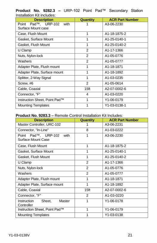
Product No. 9282.3 – URP-102 Point Pad™ Secondary Station Installation Kit includes:
Description Quantity ACR Part Number
Point Pad™, URP-102 with Surface Mount case
1 A3-06-2230
Case, Flush Mount 1 A1-18-1875-2
Gasket, Surface Mount 1 A1-25-0140-1
Gasket, Flush Mount 1 A1-25-0140-2
U Clamp 2 A1-17-1366
Nuts, Nylon-lock 2 A1-05-0776
Washers 2 A1-05-0777
Adapter Plate, Flush mount 1 A1-18-1871
Adapter Plate, Surface mount 1 A1-18-1892
Splitter, 2-Way Signal 1 A1-03-0235
Screw, #6 2 A1-05-0614
Cable, Coaxial 15ft A2-07-0002-6
Connector, "F" 4 A1-03-0220
Instruction Sheet, Point Pad™ 1 Y1-06-0179
Mounting Templates 1 Y1-03-0138-1
Product No. 9283.3 – Remote Control Installation Kit Includes:
Description Quantity ACR Part Number
Master Controller, URC-102 1 A3-06-2231
Connector, "In-Line" 8 A1-03-0222
Point Pad™, URP-102 with Surface Mount Case
1 A3-06-2230
Case, Flush Mount 1 A1-18-1875-2
Gasket, Surface Mount 1 A1-25-0140-1
Gasket, Flush Mount 1 A1-25-0140-2
U Clamp 2 A1-17-1366
Nuts, Nylon-lock 2 A1-05-0776
Washers 2 A1-05-0777
Adapter Plate, Flush mount 1 A1-18-1871
Adapter Plate, Surface mount 1 A1-18-1892
Cable, Coaxial 15ft A2-07-0002-6
Connector, "F" 2 A1-03-0220
Instruction Sheet, Master Controller
1 Y1-06-0178
Instruction Sheet, Point Pad™ 1 Y1-06-0179
Mounting Templates 1 Y1-03-0138
Y1-03-0138V 22
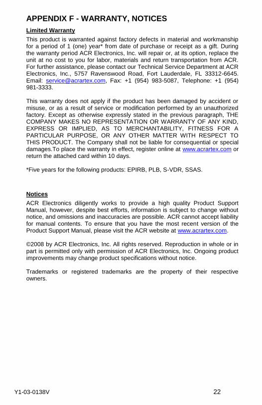
APPENDIX F - WARRANTY, NOTICES
Limited Warranty
This product is warranted against factory defects in material and workmanship for a period of 1 (one) year* from date of purchase or receipt as a gift. During the warranty period ACR Electronics, Inc. will repair or, at its option, replace the unit at no cost to you for labor, materials and return transportation from ACR. For further assistance, please contact our Technical Service Department at ACR Electronics, Inc., 5757 Ravenswood Road, Fort Lauderdale, FL 33312-6645. Email: [email protected], Fax: +1 (954) 983-5087, Telephone: +1 (954) 981-3333. This warranty does not apply if the product has been damaged by accident or misuse, or as a result of service or modification performed by an unauthorized factory. Except as otherwise expressly stated in the previous paragraph, THE COMPANY MAKES NO REPRESENTATION OR WARRANTY OF ANY KIND, EXPRESS OR IMPLIED, AS TO MERCHANTABILITY, FITNESS FOR A PARTICULAR PURPOSE, OR ANY OTHER MATTER WITH RESPECT TO THIS PRODUCT. The Company shall not be liable for consequential or special damages.To place the warranty in effect, register online at www.acrartex.com or return the attached card within 10 days. *Five years for the following products: EPIRB, PLB, S-VDR, SSAS.
Notices
ACR Electronics diligently works to provide a high quality Product Support Manual, however, despite best efforts, information is subject to change without notice, and omissions and inaccuracies are possible. ACR cannot accept liability for manual contents. To ensure that you have the most recent version of the Product Support Manual, please visit the ACR website at www.acrartex.com. ©2008 by ACR Electronics, Inc. All rights reserved. Reproduction in whole or in part is permitted only with permission of ACR Electronics, Inc. Ongoing product improvements may change product specifications without notice. Trademarks or registered trademarks are the property of their respective owners.
Y1-03-0138V 23
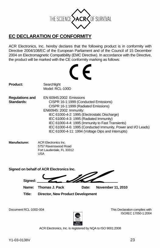
EC DECLARATION OF CONFORMITY
ACR Electronics, Inc. hereby declares that the following product is in conformity with Directive 2004/108/EC of the European Parliament and of the Council of 15 December 2004 on Electromagnetic Compatibility (EMC Directive). In accordance with the Directive, the product will be marked with the CE conformity marking as follows:
Product: Searchlight
Model: RCL-100D
Regulations and EN 60945:2002: Emissions Standards: CISPR 16-1:1999 (Conducted Emissions)
CISPR 16-1:1999 (Radiated Emissions) EN60945: 2002: Immunity:
IEC 61000-4-2: 1995 (Electrostatic Discharge) IEC 61000-4-3: 1995 (Radiated Immunity) IEC 61000-4-4: 1995 (Immunity to Fast Transients) IEC 61000-4-6: 1995 (Conducted Immunity, Power and I/O Leads) IEC 61000-4-11: 1994 (Voltage Dips and Interrupts)
Manufacturer: ACR Electronics Inc. 5757 Ravenswood Road Fort Lauderdale, FL 33312 USA
Signed on behalf of ACR Electronics Inc.
Signed: __________________________________________
Name: Thomas J. Pack Date: November 11, 2010
Title: Director, New Product Development
Document RCL-100D-004 This Declaration complies with ISO/IEC 17050-1:2004
ACR Electronics, Inc. is registered by NQA to ISO 9001:2008